vistar ii/hz - mirror service€¦ · technical user's manual vistar ii/hz . infoton. second...
TRANSCRIPT

TECHNICAL USER'S MANUAL
VISTAR II/HZ

INFOTON. SECOND AVENUE, BURLINGTON, MASSACHUSETTS 01803. AREA CODE 617 272-6660 01 VISION OF OPTICAL SCANNING CORPORA TION
INFOTON
FUNCTIONAL SPECIFICATION NO. 00lA
VISTAR II/HZ
Revised May 23, 1975


INFOTON. SECOND AVENUE, BURLINGTON, MASSACHUSETTS 01803. AREA CODE 817 272·8880 DIVISION OF OPTICAL SCANNING CORPORATION
TABLE OF CONTENTS
SECTION I Page
1.0 INTRODUCTION 1
SECTION II
2.0 SUMMARY OF CHARACTERISTICS · • · · · · · · · · 2
2.1 Interchangeable with Teletype · · · · 2.2 Easy to Read . · · · · · · · · · · · · · 2.3 High-Speed Transmission Rates · · · · · · 2.4 Choice of Computer Interface 2.5 Protected Date · · · · · · · · · · · 2.6 Roll or Page Mode · · · · · · · · · · 2.7 Cursor Control · · · • · · · · · · · 3 2.8 Cursor Addressing · · · · · · · · · · 2.9 Erase Page and Erase Field · · · 2.10 Transmission Modes · · · · · · · · .. 2.11 Print Mode . . · · · · · · · 2.12 Lower Case Character Option · · · · · 2.13 Factory Programmability · · · 4
SECTION III
3.0 VISTAR II SPECIFICATIONS · · · · · · · · · · · 5
3.1 Remote Keyboard · · · · · · . · · · 3.2 Screen Format · · · · · · · · · 3.3 Mechanical · . · · · · · · · · · 3.4 Environmental · · · · · · · · · · · 3.5 Controls, Switches and Connectors · · · 3.6 Electrical · · · · · · · · · · · 6 3.7 Standard . · . · · · · · · · . ·
SECTION IV
4.0 FUNCTIONAL DESCRIPTION ...•.•••.... 7
4.1 Local/On Line ..••..•••. 4.2 Character Mode ......•....... 4.3 Block Operation . . • . . •. . .•. 8 4.4 Protected Data. . • •. . ..•• 4.5 Editing Option.. • .....•... 9
Page i 12-30-74

INFOTON. SECOND AVENUE, BURLINGTON, MASSACHUSETTS 01803. AREA CODe 617 272-6660 DIVISION OF OPTICAL SCANNING CORPORATION
TABLE OF CONTENTS (Con 'd)
SECTION V Page
5.0 OPERATIONAL FEATURES. . . • . . • • . 10
5.1 Teletypewriter Compatibility · 5.2 Cursor · · · · · · · • · · · • 5.3 Cursor Addressing · · · · · · 5.4 Roll Mode · · · · · · · 5.5 Page Mode · · · · · · · · · 5.6 Response to Commands · · · 5.7 Erase Page · · · · · · 5.8 Erase Field · · · · · · · · · · 5.9 Bell · · · · • · · · · 5.10 Carriage Return · · · · · · · · 5.11 Line. Feed · · · · • · · · · 5.12 Null · · · · · · · · · · · · · 5.13 Break · · · · · · · · · 5.14 Rubout · · · · · · 5.15 Home · · · · · · \ · · · · 5.16 Cursor Right · · · · · · · 5.17 Cursor Left · · · · · · · · · · 5.18 Cursor Up · · · · · · · 5.19 Cursor Down · · · · · · 5.20 Transmit Field · · · · · · 5.21 Transmit Page · · · · · · ·
SECTION VI
6.0 EQUIPMENT DESCRIPTION
6.1 6.2 6.3 6.4
Keyboard . . . . . . • • • . Display . . • . Control Logic . . • • . . . Controls ..•. . . . · .
SECTION VII
7.0 INTERFACE
· · · •
· •
· · · · · · · ·
· · · · · · · · · · · · · ·
7.1 Asynchronous Serial Interface ...
11
16
17
18
19
20
23
25
7.2 Wiring of the Current Loop Interface 29 7.3 Printer Interface. . • . . . • .. 32
Page ii 12-30-74
INFOTON. SECOND AVENUE, BURLINGTON, MASSACHUSETTS 01B03. AREA CODE 617 272·6660 DIVISION OF OPTICAL SCANNING CORPORA TION
TABLE OF CONTENTS (cont'd)
SECTION VIII
8.0
SECTION IX
9.0
COMPATIBILITY WITH OTHER INFOTON SERISS DISPLAY TERMINALS . . .. •. .
8.1 Screen Size . . . . ....• 8.2 Blink Mode. . . .. . .......• 8.3 Page Mode Code. . . . .. . .•. 8.4 3600 BPS Speed. . ..•.......
OPERATING INSTRUCTIONS
9.1 9.2
Initial Setup .. ... Establish Communication
. . . ,. .
33
34
Page iii 12-30-74

INFOTON. SECOND AVENUE, BURLINGTON, MASSACHUSETTS 01B03· AREA CODE 617 272-6660 DI VISION OF OPTICAL SCANNING CORPORA TION
SECTION V
5-1
5-2
5-3
SECTION VI
6-1
6-2
0-3
6-4
SECTION VII
7-1
7-2
7-3
SECTION X
APPENDIX A
APPENDIX B
APPENCIX C
LIST OF FIGURES
Title
Character Layout/Format
Example of Formatting without Cursor Addressing
Example of Formatting Making use of Cursor Addressing
Dot Matrix Character Format
Dot Matrix with Cursor
Lower Case Dot Matrix
Placement of TV Controls
VISTAR II Interface Panel
Wiring to VISTAR II Current Loop Terminal Strip
I/O Rates as a Function of Distance
VISTAR II Code Chart
VISTAR II Asynchronous Serial Interface EIA Signals and Pin Connections
VISTAR II Keyboard Layout
Page iv
Page
12
13 & 14
15
21
21
22
24
27
30
31
36,37,&38
39
40
12-30-74

INFOTON. SECOND AVENUE, BURLINGTON, MASSACHUSETTS 01803. AREA CODE 617 272-6660 DIVISION OF OPTICAL SCANNING CORPORA TION
Page 1
1.0 INTRODUCTION
The INFOTON VISTAR II Display Terminal is an alphanumeric display designed for use with an on-line computer as a high speed, silent, interactive terminal device. It can be utilized as a substitute for a TELETYPE® in either an unbuffered (character-by-character) conversational mode or in a buffered (block) mode transmitting either a field, line or a page at a time. As a completely self-contained desk-top unit, the VISTAR II is ideally suited for high-speed, two way data communications. Incorporated into each unit is a keyboard, power supply, video presentation control, refresh electronics and both an RS-232C and current loop interface for on-line connection to a MODEM, or computer.
® Registered trademark of TELETYPE Corporation.
SECTION I Revised 12-30-74

INFOTON. SECOND AVENUE, BURLINGTON, MASSACHUSETTS 01803. AREA CODE 617 272-6660 DIVISION OF OPTICAL SCANNING CORPORATION
Page 2
2.0 SUMMARY OF CHARACTERISTICS
2.1 INTERCHANGEABLE WITH TELETYPE
The VISTAR II can be substituted for a Model 33, 35, 37, or 38 TELETYPE with no hardware or software modifications. The VISTAR II can serve as an upgraded high-speed terminal to all time-sharing services using ASCII* Code regardless of the computer system used by the service.
2.2 EASY-TO-READ CHARACTERS
High resolution, non-reflecting screen, and contrastenhancing filter permits easy viewing at distances up to 10 feet under direct glare and 100 foot-candle illumination.
2.3 HIGH-SPEED TRANSMISSION RATES
Eleven switch-selectable transmission rates from 75 to 9600 bits per second are provided.
2.4 CHOICE OF COMPUTER INTERFACE
The unit is supplied with two forms of an asynchronous serial interface; i. e. , standard E IA RS - 2 32C and 20 or 60 rna. TTY style current loop.
2.5 PROTECTED DATA
Protected data appears on the VISTAR II in reduced intensity and unprotected data or variable data in highlighted intensity. This is also referred to respectively as background and foreground. Only variable data can be acted upon by the use of keyboard.
The start of each variable field is a tab stop which is used in conjunction with the tab key. When the tab key is depressed, the cursor advances to the first position in the next field.
2.6 ROLL OR PAGE MODE
In character mode the terminal is always in Roll Mode. I~ block mode received data is in roll mode; keyboard generated data is in page mode.
* American Standard Code for Information Interchange
SECTION II Revised 12-30-74
INFOTON. SECOND AVENUE, BURLINGTON, MASSACHUSETTS 01803. AREA CODE 617 272-6660 DIVISION OF OPTICAL SCANNING CORPORATION
Page 3
2.7 CURSOR CONTROL
The unit has a non-destructive position marker (cursor) displayed as a blinking underscore. The cursor position can be manipulated to any position on the screen by: a) the computer using direct cursor address or b) the operator using any combination of the five cursor
control keys on the keyboard.
2.8 CURSOR ADDRESSING
Under computer control, the cursor can be directly positioned to any location on the screen. This is a multi code cummand sequence. See also item 5.3 in Section V of the Functional Description.
2.9 ERASE FOREGROUND AND ERASE ALL
2.10
2.11
2.12
Erase Foreground erases all "foreground" (unprotected) data and places cursor at home position. The ERASE ALL command will erase all protected and unprotected data and put the cursor in the home position. The ERASE FOREGROUND and ERASE all keys do not send any data. They just perform their assigned functions.
TRANSMISSION MODES
The VISTAR II may operate either in a Character-by Character transmission mode, exactly as a TELETYPE, or in Block Mode, in which data is not sent until a transmit command is generated. The choice of modes is made by a convenient back panel switch.
PRINTER MODE INTERFACE OPTION
The VISTAR II optionally offers a convenient connection for an external peripher~l d~vice such as a printer. Data transmission initiation to such a peripheral is availabl~ by a print key located on the keyboard or from the data line. Interfore will be serial 20 rna current loop and RS232 or TTL parallel.
LOWER CASE CHARACTER GROUP OPTION
This option permits the unit to display the 94 character ASCII set, which includes lower case alphabet characters. The additional characters are displayed on a 5 x 9 dot matrix, to allow an adequate presentation of characters with descenders (namely g, j, p, q, and y).
SECTION II Revised 12-30-74
2.13
INFOTON. SECOND AVENUE, BURLINGTON, MASSACHUSETTS 01803. AREA CODE 617 272·6660 DIVISION OF OPTICAL SCANNING CORPORA TlON
FACTORY PROGRAMMABILITY
This has no validity for HZ version.
Page 4
SECTION II Revised 12-30-74

INFOTON. SECOND AVENUE, BURLINGTON, MASSACHUSETTS 01803. AREA CODE 617 272-666Q DIVISION OF OPTICAL SCANNING CORPORA TION
Page 5
3.0 VISTAR II SPECIFICATIONS
3.1 The VISTAR II is equipped with a remote keyboard for ease of use and operational convenience. The 5 ft. long cable for the remote keyboard is plugged into a corresponding connector at the rear of the display unit. Connector shape assures correct connector mating.
3.2
3.3
3.4
3.5
SCREEN FORMAT
Characters per line Lines per display
80 24
Character set 96 character ASCII upper/lower case Character format 5 x 9 dot matrix . Character size Refresh rate
0.08 inch x 0.19 inch, nominal 50 Hz or 60 Hz
Display Area Color White - P4
8~ inches x 6 inches White - P4 phosphor
Readability Screen easily read without disruptive reflections in a 100 foot illumination.
MECHANICAL
Size
Weight
13 3/4 inches high, 17 inches wide, 15 inches deep, excluding keyboard 40 pounds
ENVIRONMENTAL
Operating temperature Storage temperature
00 to 500 C -30 0 to 70 0 C
Humidity o to 95% non-condensing
CONTROLS, SWITCHES AND
On/Off Switch Local/On Line Switch
CONNECTORS Front
X
TV Vertical Hold Control TV Intensity Control
X
TV Horizontal Hold Control Roll/Page Switch (not applicable) Character/Block Transmission
Switch Copy switch Received Data Rate Selector Transmitted Data Rate Selector Full/Half Dup lex Switch 10/11 Bit Code Switch Automatic Carriage Return/EOT Switch Odd/Even/Mark Parity Switch Current Loop Wiring Strip EIA Connector External Video Connector 115/230 Volt Wiring Connections 50/60 Hz Refresh Switch
SECTION III
Side Rear Internal
X X X
X X
X X X X X X· X X X X
X X
Revised 5-23-75
INFOTON .SECOND AVENUE, BURLINGTON, MASSACHUSETTS 01803. AREA CODE 617 272·6660 DIVISION OF OPTICAL SCANNING CORPORA TION
3.6
3.7
Page 6
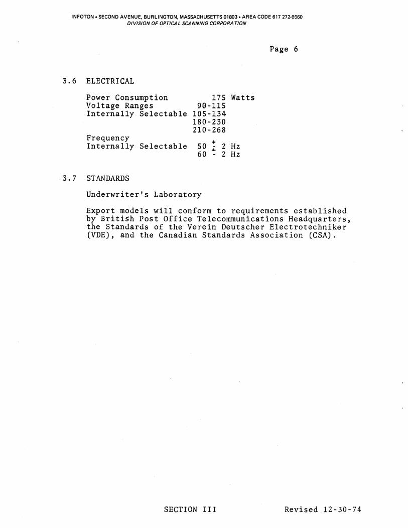
ELECTRICAL
Power Consumption 175 Watts Voltage Ranges 90-115 Internally Selectable 105-134
180-230 210-268
Frequency + Internally Selectable 50 .; 2 Hz
60 - 2 Hz
STANDARDS
Underwriter's Laboratory
Export models will conform to requirements established by British Post Office Telecommunications Headquarters, the Standards of the Verein Deutscher Electrotechniker (VDE) , and the Canadian Standards Association (CSA).
SECTION III Revised 12-30-74

INFOTON. SECOND AVENUE, BURLINGTON, MASSACHUSETTS 01803. AREA CODE 617 272·6660 DIVISION OF OPTICAL SCANNING CORPORA TlON
Page 7
4.0 FUNCTIONAL DESCRIPTION
The VISTAR II Display Terminal is a self-contained desk top unit whicll can be used as a plug-for-plug replacement for a TELETYPE. The unit consists of a keyboard, video monitor, refresh memory, control logic, and serial data interface. The modes of operation and communications are described in the following paragraphs.
4.1 LOCAL/ON LINE
In LOCAL, the VISTAR II is disconnected from the data line but is functional in all other respects. The LOCAL position is used for demonstration and testing purposes. The LOCAL/ ON LINE selection is made by a switch on the keyboard.
The remainder of the description refers to various types of ON LINE operations.
4.2 CHARACTER MODE
In the Character Mode the keyboard communicates only to the interface transmitter, and only the interface receiver communicates to the display memory. All transmissions are on a character-by-character basis. All codes generated by the keyboard including control or function codes, go directly to the transmitter and then to the data lines.
When in Character Mode, the VISTAR II may be placed in full or half duplex. In half duplex the interface receiver is actuated in series with the transmitter and transmitted codes are routed back through the receiver and displayed. Control codes either perform their specific function (e.g. BELL, CURSOR HOME, etc.) or are ignored.
In full duplex the receiver is independent of the transmitter. Only data received from the data line will appear on the display. As in half duplex, control codes either perform their specific function or are ignored. In full duplex, therefore, information will be displayed only if the computer at the end of the data line "echoes" back the information transmitted from the keyboard. Simultaneous independent operation of the Receiver and Transmitter is utilized. In Character Mode all data appears as background intensity unless the terminal is instructed to display foreground intensity by using "Display Foreground" command (from data line or two key command from keyboard). The terminal, in Character Operation, is always in Roll Mode.
4.3 BLOCK OPERATION
In Block Mode the keyboard communicates directly to the memory of the VISTAR II. After the message has been entered from the keyboard, the operator may initiate a transmission by depressing XMIT key. If protected data is on the screen, only
SECTION IV Revised 12-30-74

INFOTON. SECOND AVENUE, BURLINGTON, MASSACHUSETTS 01803. AREA CODE 617 272·6660 DIVISION OF OPTICAL SCANNING CORPORATION
Page 8
4.3 BLOCK OPERATION (Con'd)
the unprotected, or variable data will be transmitted.
1MIT key places End of Transmission symbol (block) at current cursor location. Causes the cursor to back to either of two locations: (1) The first character position of the line following the previous End of Transmission symbol, or (2) If location in (1) is not present, to Home. At this point transmission begins, and continues up to the End of Transmission character after which a single CR or EOT code (depending on switch position) is sent.
Depression of the BREAK key places a space condition on the data line and terminates any transmission in progress. Detection of a BREAK condition by the receiver also terminates any transmission in progress.
In Block Mode, data received from the data line is presented directly to the display. Control codes received from the data line cause their associated function to occur and are not stored in memory. However, during transmission from the display, the receiver is disabled (except for detecting BREAK) .
4.4 PROTECTED DATA
Protected data can be utilized in Block Mode. Protected data is normally initiated from the data line only. Protected data may also be entered from the keyboard by a mUlti-key sequence. In character mode protected data appears in a reduced intensity and variable data in a highlighted intensity. Variable data bounded by protected data defines a field. The field does not include the protected characters at either end; therefore, a field can be as short as one character or as long as 1919 characters. There is no other limitation on the number, placement or length of fields, within the 1920 character memory.
When data is keyed in, the cursor will advance one position per character. On keyboard entry, when background data is encountered, cursor will move through said background data on a one character per keystroke rate without altering any of said background characters. Therefore, all keyboard data entered during the background field is lost (ignored).
When using background/foreground in setting up a form, protected fields are created on the screen, in which the tab feature can be used. The beginning of each foreground field becomes an invisible tab stop. If there is no protected field (background data) between the present cursor position and the lower right hand corner of the screen, the cursor advances to the lower right hand corner and halts there.
SECTION IV Revised 5-23-75

INFOTON. SECOND AVENUE, BURLINGTON, MASSACHUSETTS 01B03. AREA CODE 617 272·6660 DIVISION OF OPTICAL SCANNING CORPORA TlON
4.5 EDITING
The cursor is always used used in Block Mode only. keys, position the cursor required as follows:
Page 9
when editing data. Editing can be By manipulating the cursor control at the location where editing is
A. Insert Line - Position the cursor at any location in the row where the new line is desired and depress the IlL key. All data starting with the data in the row where the cursor resides will shift down one line. Data on the 24th line will be lost.
B. Delete Line - Position the cursor at any location in the line to be deleted and depress the PIL key. All data will move up one line. The line of data in which the cursor resides will be lost and the 24th line will be unprotected blanks.
C. Insert Character - Position the cursor under the location where the new character is to be inserted. Depress the IIC key to place the unit in the "Insert Mode" (I/C key illuminates). Depress the key for the character to be inserted. All data and the cursor shift one position to the right with the last character in the line wrapping around to the first location of the next line. This action is repeated on each line. To exit from Insert Character Mode, press the Insert Character key again, (the IIC lamp is extinguished). The Insert Character Mode does not affect protected data. If protected data is encountered before the insert operation reaches the end of the screen, it terminates at that point.
D. Delete Character - Position the cursor under the character to be deleted and depress the DIC key. All data to the right of the cursor will move one position to the left until either the last character of the last line or the last character in the variable field is encountered.
SECTION IV Revised 5-23-75
INFOTON. SECOND AVENUE, BURLINGTON, MASSACHUSETTS 01803. AREA CODE 617 272-6660 DIVISION OF OPTICAL SCANNING CORPORA TlON
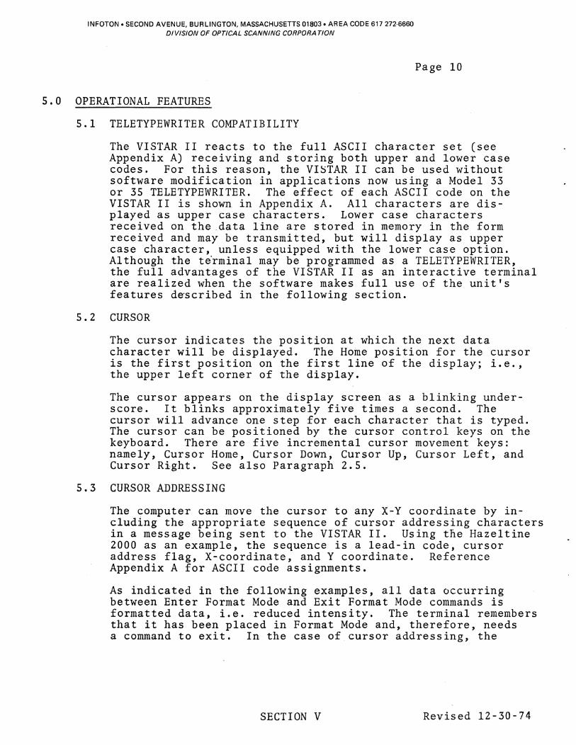
5.0 OPERATIONAL FEATURES
5.1 TELETYPEWRITER COMPATIBILITY
Page 10
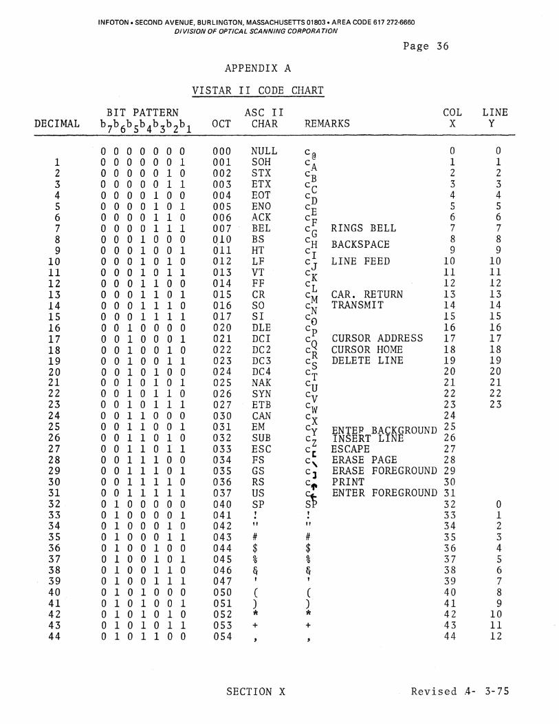
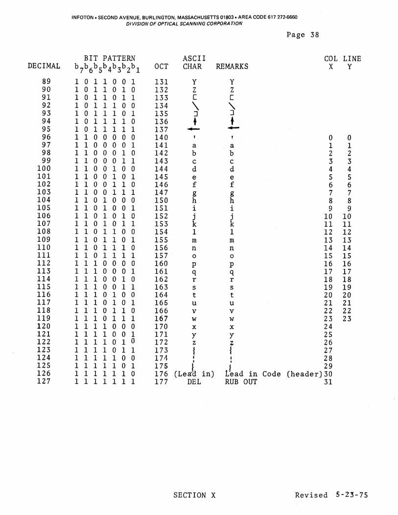
The VISTAR II reacts to the full ASCII character set (see Appendix A) receiving and storing both upper and lower case codes. For this reason, the VISTAR II can be used without software modification in applications now using a Model 33 or 35 TELETYPEWRITER. The effect of each ASCII code on the VISTAR II is shown in Appendix A. All characters are displayed as upper case characters. Lower case characters received on the data line are stored in memory in the form received and may be transmitted, but will display as upper case character, unless equipped with the lower case option. Although the t~rminal may be programmed as a TELETYPEWRITER, the full advantages of the VISTAR II as an interactive terminal are realized when the software makes full use of the unit's features d~scribed in the following section.
5.2 CURSOR
The cursor indicates the position at which the next data character will be displayed. The Home position for the cursor is the first position on the first line of the display; i.e., the upper left corner of the display.
The cursor appears on the display screen as a blinking underscore. It blinks approximately five times a second. The cursor will advance one step for each character that is typed. The cursor can be positioned by the cursor control keys on the keyboard. There are five incremental cursor movement keys: namely, Cursor Home, Cursor Down, Cursor Up, Cursor Left, and Cursor Right. See also Paragraph 2.5.
5.3 CURSOR ADDRESSING
The computer can move the cursor to any X-Y coordinate by including the appropriate sequence of cursor addressing characters in a message being sent to the VISTAR II. Using the Hazeltine 2000 as an example, the sequence is a lead-in code, cursor address flag, X-coordinate, and Y coordinate. Reference Appendix A for ASCII code assignments.
As indicated in the following examples, all data occurring between Enter Format Mode and Exit Format Mode commands is formatted data, i.e. reduced intensity. The terminal remembers that it has been placed in Format Mode and, therefore, needs a command to exit. In the case of cursor addressing, the
SECTION V Revised 12-30-74
INFOTON. SECOND AVENUE, BURLINGTON, MASSACHUSETTS 01B03. AREA CODE 617 272·6660 DIVISION OF OPTICAL SCANNING CORPORATION
Page 11
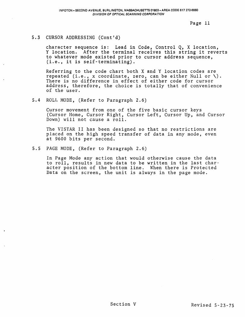
5.3 CURSOR ADDRESSING (Cont'd)
character sequence is: Lead in Code, Control Q, X location, Y location. After the terminal receives this string it reverts to whatever mode existed prior to cursor address sequence, (i.e., it is self-terminating).
Referring to the code chart both X and Y location codes are repeated (i.e., x coordinate, zero, can be either Null or \). There is no difference in effect of either code for cursor address, therefore, the choice is totally that of convenience of the user.
5.4 ROLL MODE, (Refer to Paragraph 2.6)
Cursor movement from one of the five basic cursor keys (Cursor Home, Cursor Right, Cursor Left, Cursor Up, and Cursor Down) will not cause a roll.
The VISTAR II has been designed so that no restrictions are placed on the high speed transfer of data in any mode, even at 9600 bits per second.
5.5 PAGE MODE, (Refer to Paragraph 2.6)
In Page Mode any action that would otherwise cause the data to roll, results in new data to be written in the last character position of the bottom line. When there is Protected Data on the screen, the unit is always in the page mode.
Section V Revised 5-23-75

L
I
\f) N tTl E n >-3 S H 0 Z
<:
C H A RAe T E R S
1 5 10 15 20 25 30 35 40 45 50 55 60 65 70 75 80
1~ 2 C 3
4 5 6
7
8
9
10
11
12
13
14
15
20~~~~~~~~~~~~~~~~~~~~~~~~~~~~~~~~~~~~~~~~~~~~ 21~~~~~~~~~~~~~ww~~~~~~~~~~~~~~~~~w-~~~~~~~~~~~~ 221-4~~~~~~~~~~~~~WL~~~JJ~~~~~~~~~~~~~~~~~~~~~~~~~ 23~~~~~~~~~~~~~~~"~~~~~~.~~~~~~~~~~~~~~~~~~~~~~-L~~~
24~~~~
Figure 5-1 Character Layout Format
'"0 III
oq ('l)
...... tv
2
" o -I o 2
(II m
" o 2 o l>
0;:;; -2 :Sc ~_m Om <:c O:D ."r 02 "'G) :j-l
~~ ,....-(I):;;: ~l; <:(11 <:l> -" <::I: G)C C")~ 0-1 ::Q-I ",(11 00 JJ~
l>~ :jW o • <:l>
:D m l>
" o o m 0>
......
'" ...... '" a, :5l o
INFOTON. SECOND AVENUE, BURLINGTON, MASSACHUSETTS 01803. AREA CODE 617 272·6660 DIVISION OF OPTICAL SCANNING CORPORATION
Page 13
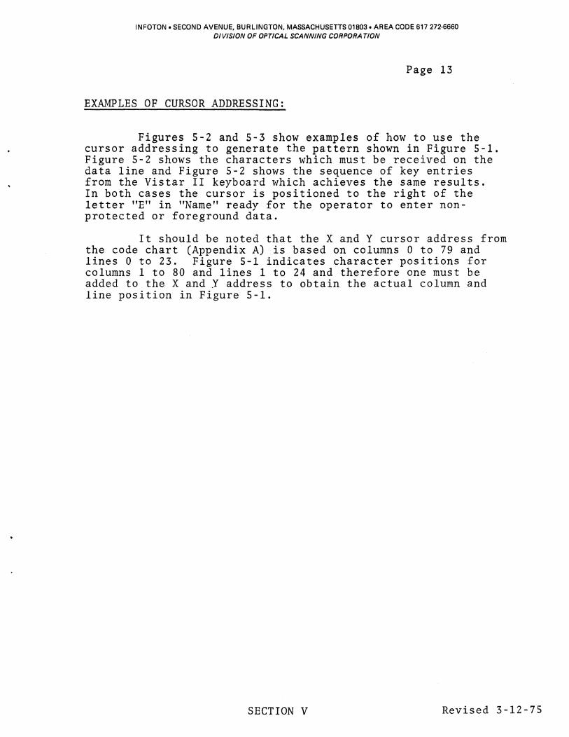
EXAMPLES OF CURSOR ADDRESSING:
Figures 5-2 and 5-3 show examples of how to use the cursor addressing to generate the pattern shown in Figure 5-1. Figure 5-2 shows the characters which must be received on the data line and Figure 5-2 shows the sequence of key entries from the Vistar II keyboard which achieves the same results. In both cases the cursor is positioned to the right of the letter "E" in "Name" ready for the operator to enter nonprotected or foreground data.
It should be noted that the X and Y cursor address from the code chart (Appendix A) is based on columns 0 to 79 and lines 0 to 23. Figure 5-1 indicates character positions for columns 1 to 80 and lines 1 to 24 and therefore one must be added to the X and Y address to obtain the actual column and line position in Figure 5-1.
SECTION V Revised 3-12-75

NAME Lead In
FS N
A
M
E
Lead In
DCl SI Null A
G
E
Lead In
CR C
o M
M
E
N
T
S
Lead In
DC1 EOT Null
INFOTON. SECOND AVENUE, BURLINGTON, MASSACHUSETTS 01803. AREA CODE 617 272-6660 DIVISION OF OPTICAL SCANNING CORPORATION
Page 14
Figure 5-2
EXAMPLE OF FORMATTING MAKING USE OF CURSOR ADDRESSING FROM DATA LINE
CODE 1768
034 8 1168 101 8 115
8 1058 1768
021 8 017 8 000 8 101 8 107 8 105 8 1768
015 8 1038
1178 1158 115 8 105 8 1168
124 8 123 8 1768
0218 004 8 000 8
EFFECTIVE KEY "-I
M
CR C
o M
M
E
N
T
S
COMMENTS Prepares for change in format or cursor address Erase screen and places cursor at home Da ta (format) Data (format) Data (format) Data (format) Prepares for a cursor address or change in format Cursor address flag X address = 14 (see code chart) Y address = 0 (see code chart)· Data (format) Data (format) Data (format) Prepares for change in format or cursor address Performs non-stored new line function Data Data Data Data Data Data (format) Data (format) Data (format) Prepares for a change in format or cursor address Cursor address flag X address = 4 (see code chart) Y address = 0 (see code chart)
SECTION V Revised 5-23-75

NAME
Lead In
EM Lead In FF N
A
M
E
Lead In DC1 SI Null A
G
E
Lead In CR C
o M
M
E
N
T
S
Lead In DCl EOT Null Lead In US
INFOTON. SECOND AVENUE, BURLINGTON, MASSACHUSETTS 01803. AREA CODE 617 272-6660 DIVISION OF OPTICAL SCANNING CORPORA TION
Page 15 Figure 5-3
EXAMPLE OF FORMATTING MAKING USE OF CURSOR ADDRESSING FROM KEYBOARD
CODE
176 8
031 8 1768
0348 116 8 101 8 115 8 105 8 1768
0218 017 8 000 8 101 8 107 8 105 8 1768 015 8 1038 117 8 115 8 115 8 105 8 1168 1248 1238 1768 0218 0048 000 8 176a 037 8
EFFECTIVE KEY
cQ cN c@ A
G
E ,.J
CR C
o M
M
E
N
T
S
tI""V'
COMMENTS
Prepares for change in format or cursor address Enter format mode
Erase screen and places cursor at home Data (format) Data (format) Data (format) Data (format)
Cursor address flag X addr~ss = 14 (see code chart) Y address = 0 (see code chart) Data (format) Data (format) Data (format)
Performs non-stored new line function Data (format) Data (format) Data (format) Data (format) Data (format) Data (format) Data (format) Data (format)
Cursor address flag X address = 4 (see code chart) Y address = 0 (see code chart)
Exit format mode
SECTION V Revised 5-23-75

INFOTOI'j. SECOND AVENUE, BURLINGTON, MASSACHUSETTS 01803. AREA CODE 617 272-6660 01 VISION OF OPTICAL SCANNING CORPORA TION
5.6 RESPONSE TO COMMANDS
Page 16
The VISTAR II terminal is controlled and manipulated from its data stream. The data stream control logic is defined as follows:
a) Certain characters are designated as command characters (Appendix A)
b) The computer inserts these command characters within the text transmitted to the VISTAR II.
c) The VISTAR II continually monitors the input data stream for these command characters, performing a designated action upon reception of a command character.
For example, when an Erase All command character is received by the VISTAR II, the unit erases all characters and then examines the next character in the data stream to determine what action is to be taken.
A description of the commands used to control the display follows.
5.7 ERASE ALL
All data on the screen is erased. Cursor moves to Home position.
5.8 ERASE FOREGROUND
Erases all foreground data and cursor moves to home. When a memory location is erased a SPACE code is stored in that position rather than a NULL code.
5.9 BELL
The Bell will sound for the following conditions:
a) Block Mode - The introduction of the 70th character on a line from the keyboard. The bell will not sound if a Bell Code is being transmitted from memory, nor if the cursor moves into the 70th position while the display is receiving or transmitting data.
b) Character Mode - Receipt of the Bell Code (Control G) from the data line rings the bell.
SECTION V Revised 5-23-75

INFOTON. SECOND AVENUE, BURLINGTON, MASSACHUSETTS 01803. AREA CODE 617 272·6660 DIVISION OF OPTICAL SCANNING CORPORATION
Page 17
5.10 CARRIAGE RETURN
Places the cursor in the left-most position of the line following the line in which the cursor resides, provided (1) Cursor is not on the bottom line in which case it performs carriage return only, (2) Command is initiated from the keyboard. If the·command is received from the data line preceded by a lead in code, the above function will be performed. If it is not preceded by a lead in code, a carriage return code wilr-De stored in memory at the location specified by the cursor, and the cursor will move to the leftmost position of the next line.
5.11 LINE FEED
This key causes the line feed character to be transmitted when operating in full as half duplex mode, but has no other effect. It does not move the cursor down the screen and does not cause the line feed character to be stored. In BATCH mode the character is stored in memory.
5.12 NULL
No action is taken when this code appears on the data line. This code is generated from the keyboard by "Control @".
5 .13 BREAK
Depressing the break key forces a "spacing" condition on the data line as long as the key is depressed. Detecting a "Break" Code terminates any Transmit Function when in Block Mode.
5.14 RUBOUT
Causes a rubout code (all one bits) to be transmitted only in Character Mode. No cursor movements occur and no character enters memory. In Block Mode, depression of the rubout key is ignored.
5.15 HOME
Places the cursor in the first character position of the first line. The HOME key transmits no data on the data line.
SECTION V Revised 5-23-75

INFOTON. SECOND AVENUE, BURLINGTON, MASSACHUSETTS 01803. AREA CODE 617 272·6660 DIVISION OF OPTICAL SCANNING CORPORATION
Page 18
5.16 CURSOR RIGHT
Places the cursor one position to the right of its current position. If the cursor is in the last column of the line, the depression of this key will cause the cursor to change
.to the first position of the next line. No data is transmitted by this key.
5.17 CURSOR LEFT
Places the cursor one position to the left of its present position. If the cursor is in the first column of a line, the depression of this key will cause the cursor to change to the last position in the preceding line. No data is transmitted by this key.
5.18 CURSOR UP
Places the cursor one line above its present position. If the cursor is in the first line, the depression of this key causes the cursor to change to the last line. No data is transmitted by this key.
5.19 CURSOR DOWN
Places the cursor one line below its present position. If the cursor is in the last line, the depression of this key causes the cursor to change to the first line. No data is transmitted by this key.
5.20 (Deleted)
5.21 TRANSMIT (XMIT)
Described in 4.3 above (Sub-paragraph 2)
SECTION V Revised 5-23-75

INFOTON. SECOND AVENUE, BURLINGTON, MASSACHUSETTS 01803. AREA CODE 617 272-6660 DIVISION OF OPTICAL SCANNING CORPORATION
Page 19
6.0 EQUIPMENT DESCRIPTION
The basic VISTAR II unit logically and physically consists of three parts - keyboard, display and control. These components and the controls and indicators on the unit are described in this section.
6.1 KEYBOARD
The operator interacts with the VISTAR II and the computer via the remote keyboard shown in Appendix C.
The VISTAR II keyboard is composed of four functional sections; namely, a set of A/N keys similar in placement to those of a typewriter, an eleven-key numeric pad, a set of five cursor movement keys and twelve function keys.
Appendix A illustrates the full code set, how to generate the codes from the keyboard, and the effect of the codes on the display.
Bot~ the SHIFT key and the CTR~ (Control) key establish a mode for the keyboard; i.e., data is not actually generated until a coded key is depressed. Depressing the SHIFT key in conjunction with another key causes upper case characters to be transmitted. The keyboard on the VISTAR II generates upper case codes for the alphabetic characters whether or not the SHIFT key is depressed, if the unit is upper case only. The lower case codes are generated by the VISTAR II keyboard only when equipped with lower case option. For operator convenience, two SHIFT keys are on the keyboard. Each of these keys has the same effect on the data.
Control codes are not displayed, but in most applications are used as function codes. Some of the control codes have been used as functions for the VISTAR II. For example, Control \ erases the screen and the CONTROL M code is the Carriage Return command. To simplify the entry for commands from the keyboard, function keys are provided for all commands. When depressed, the key labeled "CR" generates the Carriage Return command (Control M).
The BREAK key places a "spacing"; i.e., a logical "0" condition, on the data line for as long as the key is depressed. The BREAK key terminates any transmit function when in Block Mode.
SECTION VI Revised 5-23-75

INFOTON. SECOND AVENUE, BURLINGTON, MASSACHUSETTS 01803. AREA CODE 617 272·6660 DIVISION OF OPTICAL SCANNING CORPORATION
Page 20
6.2 DISPLAY
The display screen is a cathode ray tube (CRT) with a P4 (white) phosphor. The display area of the display is 8.5 inches wide and 6 inches high. The screen format is 24 lines, each 80 characters long.
The displayed characters are white on a dark background. The characters are generated on the display surface SO or 60 times per second to provide flicker-free viewing. Characters are displayed on the screen in a rectangular array. Each of the possible character positions on the display consists of a 7 x 10 matrix. The 5 x 7 dot matrix format is illustrated in Figure 6-1 for the letters J and K. The dot matrix forming the upper case characters is always in the upper left portion of the 7 x 10 matrix.
The position of the cursor within the 7 x 10 matrix is illustrated in Figure 6-2.
The REPEAT key, when depressed in conjunction with a coded key or function key, generates repeated transmission of the code or function at a rate of 10 characters per second.
If the unit is equipped with the Lower Case Option, lower case characters appear in a 5 x 7 dot matrix format, as illustrated in Figure 6-3.
6.3 CONTROL LOGIC
The Control Logic contains central timing and control logic, refresh memory, character generator and communications interface. The most important functions of the Control Logic are:
a) Stores in a refresh memory all data entered via the keyboard, or received over the communication line.
b) Converts the ASCII characters into dot matrix form and presents them on the CRT.
c) Maintains the display by refreshing the image at the rate of SO of 60 times per second.
d) Provides the electrical interface between the electrical operating levels of the VISTAR II and the equipment with which the terminal is operating. The interface is described in detail in Section VII.
e) Decodes command codes received on the data line and performs the appropriate function.
SECTION VI Revised 12-30-74

INFOTON. SECOND AVENUE, BURLINGTON, MASSACHUSETTS 01803. AREA CODE 617 272·6660 DIVISION OF OPTICAL SCANNING CORPORATION
+ + + + + + + + + + + +,+ + + + + + + +-+ + +"+ + + + + + + + + + + +.+ + +-+ + +'+ + + + + + + + +:+ + +-+ +~+ + + + + +.+ + + +-+ + +-+-+ + + + + + + + + + + + + +'+ +.+ + + + + +'+ + + +-+ + +'+ + +'+ + + + . . . ., . + + + + + + + + + + + + + + + + + + + + + + + + + + + + + + + + + + + + + + + + + + + + + + + + + + + + + + + + + + + +
Figure 6-1 Dot Matrix Character Format
+ + + + + + + + .+ + + + + + +
" • + + + + + + + + + + + + + + + + + + + +-+ + +.+ + +'+ + + +
" III +'+ + + + + +.+ + + + + + + + • • +-+ + + + + + + + + + + + + + + + + + +.+ + +'+ +'+ + + + + +-+ + + +.+ +.+ • + + + + + + + ., . ,
+.+ +'+ + + + + + + + + + + + CURSOR---.. t + + ;t + + + + + + + + + + +
+ + + + + + + + + + + + + + + + + + + + + + + + + + + + + +
Figure 6-2 Dot Matrix WIth Cursor
SECTION VI
Page 21
Revised 12-30-74

INFOTON. SECOND AVENUE, BURLINGTON, MASSACHUSETTS 01803. AREA CODE 617 272-6660 DIVISION OF OPTICAL SCANNING CORPORATION
+ + + + + + + + + + .+ + + + + + + + + + + + + + + + + + + + + + + + + + + + + + :+ + + + + • • • + + + + + + + + + + .+ +,.+ + +
1# + + + + + + .+ + + + + + + + + • • + + + + + + + + + + + +.+ + + • a + + + + + + -+ + + + + + +.+.+ + + + + + +-+ + + +.+ + + + + + + +-+ + • + + + + + + + + + + + + + +.+-+ + + + + + + + + + + + + + + + + + + + + + + + +
Figure 6-3 Lower Case Dot Matrix
Page 22
SECTION VI Revised 12-30-74

INFOTON. SECOND AVENUE, BURLINGTON, MASSACHUSETTS 01803. AREA CODE 617 272-6660 DIVISION OF OPTICAL SCANNING CORPORA TlON
Page 23
6.4 CONTROLS
The following two operator controls are located on the terminal:
a) ON/OFF switch is located on the front left side bottom corner of the display. In the OFF position, power is not connected to the terminal. In the ON position, the terminal is in the operating state. After the switch is turned to ON, a 30 second warm-up period is required. A light on the right side of the front bezel, glows when the switch is in the ON position.
b) LOCAL/ON LINE switch is an illuminated key switch located on the keyboard. This switch determines whether the terminal is disconnected from the data line (LOCAL not lit) or connected to the data line (ON LINE lit).
The three controls which govern the video presentation of characters are placed on the side of the unit to the operator's left. The INTENSITY knob permits the brightness of the screen to be set for th~ operator's comfort. The HORIZONTAL and VERTICAL controls, which are screw driver adjustable, allow adjustments for a stable picture. They correspond to the controls normally found on a commercial television receiver. Once these controls are set, they require infrequent adjustment.
The placement of the TV controls is shown in Figure 6-4.
SECTION VI Revised 5-23-75

INFOTON. SECOND AVENUE, BURLINGTON, MASSACHUSETTS 01803. AREA CODE 617 272·6660 DIVISION DF OPTICAL SCANNING CORPORA TION
Page 24
PLACEMENT OF TV CONTROLS
~00 I I
VERT HORZ INTENSITY
LHOLD~
FIGURE 6-4
SECTION VI

7.0 INTERFACE
INFOTON. SECOND AVENUE, BURLINGTON, MASSACHUSETTS 01803. AREA CODE 617 272-6660 01 VISION OF OPTICAL SCANNING CORPORA TION
Page 25
The VISTAR II operates with a computer over either telephone lines (via a modem) or on local connection by direct cable. The serial interface accomodates a wide range of computer systems and a wide range of data rates. This has been accomplished by adhering to commonly accepted standards for data transmission mode, transmission method (asynchronous) and transmission rate. There are no restrictions imposed by data rate limits upon any of the command codes of the VISTAR II. Thus, cursor movement commands, erase commands, etc. may be executed at the maximum rate at which the terminal can accept ordinary displaying codes. The Interface Module makes the necessary conversion between the electrical operating levels of the VISTAR II and those of the external circuit or computer with which the Interface Module is designed to operate. Also, the interface arranges data in the format required by the circuit or computer.
7.1 ASYNCHRONOUS SERIAL INTERFACE
The VISTAR II communicates in a bit-serial, character asynchronous mode. The term asynchronous is synonymous with START STOP and implies that the receiver comes to rest between characters. The START bit allows the receiving device to initiate its timing in proper synchronism with the incoming data. The STOP bites) ensures that the communication line is returned to the mark condition ready for a new START.
Transmitted data characters contain 10 or 11 bits, depending on the setting of a switch. (The Model 33 and 35 Teletype terminals transmit 11 bit code.) In receiving, the VISTAR II will operate with 10 or 11 bit formats. It is customary to use an 11 bit format at 110 baud or below, and 10 bits at higher speeds, but the VISTAR II is completely flexible both in transmission and reception.
The following bit configuration and character structure is used by the Asynchronous Interface:
Bit: 1. 2. 3. 4. 5. 6. 7 • 8. 9.
10. 11.
START - "Space" polarity - first bit transmitted b 1 - least significant data bit b 2 - data bit b 3 - data bit b 4 - data bit b 5 - data bit b 6 - data bit b 7 - most significant data bit Parity bit STOP - "mark" polarity STOP - "mark" polarity (note comments above on 11th bit)
SECTION VII Revised 12-30-74

INFOTON. SECOND AVENUE, BURLINGTON, MASSACHUSETTS 01B03. AREA CODE 617 272·6660 DIVISION OF OPTICAL SCANNING CORPORATION
Page 26
7.1 ASYNCHRONOUS SERIAL INTERFACE (Cont'd)
When the interface is transmitting, it adds the start bit, computes and adds the parity bit and adds the stop bit to every seven bit code being sent. When it is receiving, it removes the start and stop bits, and transfers only the seven information bits to the appropriate logic.
When receiving parity is checked. A code with incorrect parity is displayed as a ?
Transmission is always initiated with the start bit. Bits b 1 through b 7, shown on the preceding page, bear a oneto-one corresponc~nce with the bits b 1 through 7 of the ASCII code (ref. Appendix A). The "Space" and the "Mark" polarities are defined by the EIA Standard RS-232C*. Even parity implies that the total number of one bits in every character including the parity bit should be an even number; odd implies that it should be odd. Mark parity means that the parity bit is always s~t to 1.
The mUltipurpose interface card in the rear of the unit is shown in Figure 7-1. This interface allows a user to select a number of computer interfaces with anyone of a number of data rates.
The interface panel shown in Figure 7-1 contains:
7.1.1
7.1. 2
Rotary Switch to Select Received Data Rate
This switch has 12 positions - 75, 110, 150, 300, 600, 1200, 1800, 2400, 4800, 7200, 9600 bits per second and EXTERNAL. The external setting provides for handling data rates other than the 11 fixed rates enumerated. The external clock must be a TTL compatible pulse source cycling at 16 times the data rate (maximum data rate is 1800 char/second).
Slide Switch to Select Transmitter Data Rate The three positions on this switch are labeled 75, 110, and RECEIVE. In the RECEIVE position, data will be transmitted at the rate determined by the rotary switch. The 75 and 110 baud positions permit a lower transmission data rate than the selected reception rate. Common dual speed rates in current use are 75/1200 and 110/2400, where the first and second figures are the transmission and reception rates, respectively.
*This is the accepted interface standard for serial data transmission which is adhered to by the communication carriers. It was formulated by the Electronic Industries Association and issued as specification, RS-232. Version C is the current version of the specification.
SECTION VII Revised 12-30-74

INFOTON. SECOND AVENUE, BURLINGTON, MASSACHUSETTS 01803. AREA CODE 617 272-6660 DIVISION OF OPTICAL SCANNING CORPORA TlON
~ltse ,,0 lS
o 0 0
o 0 0
o 0 0 Q Q 0
£IA
FIGURE 7-1 VISTAR II INTERFACE PANEL
REAR PANEL, VISTAR II
Page 27
Revised 12-30-74

INFOTON. SECOND AVENUE, BURLINGTON, MASSACHUSETTS 01B03. AREA CODE 617 272-6660 DIVISION OF OPTICAL SCANNING CORPORA TlON
Page 28
7.1.3 Slide Switch to Select 10 or 11 Bit Code
The setting of this two-position slide switch determines whether transmitted characters contain 10 bits (Le., one STOP bits) or 11 bits (two STOP bits).
7.1.4 Full Duples/Half Duplex Switch
This two-position slide switch determines whether the terminal is operating in full duplex or half duplex. The position of this switch is of significance only when the terminal is in the Character Mode, as determined by the Block/Char switch. In the Block Mode, the setting of the full duplex/half duplex switch should be full duplex. The echo feature in the computer should be suppressed.
7.1.5 Automatic Carriage Return/OFF/EOT Switch
This three-position slide switch determines whether a Carriage Return code or an EOT will be automati-cally transmitted at the end of each block transmission. Its position is immaterial in Character Mode. (If not positioned in EOT, carriage return is assumed).
7.1.6 Parity Selection Switch
This three-position slide switch allows the selection of odd, even, or mark parity for both the transmitter and the receiver (in the Mark position, received parity is ignored).
7.1.7 Current Loop Wiring Strip
Depending upon the wiring to the terminal strip connector screws, the current loop interface will be 20 or 60 milliamperes, full or half duplex. (The wiring also derermines full duplex/half duplex operation in the current loop interface; the slide switch is significant only for the EIA interface and should be in the FDX position when operating curr:ent loop.)
7.1.8 EIA Connector
This MOLEX® Connector attaches to a cable supplied with a 25-pin connector equivalent to Cannon DB-19604 432 or to the Cinch Jones DB-25P consistent with RS-232C requirements. In Appendix C the pin connections for both the MOLEX and the 25-pin connectors are specified.
7.1.9 External Video Connector
A video connector provides a composite video signal to allow connection of a remote monitor at a distance of up to 100 feet.
® Trademark of Waldrom Corp. Revised 5-23-75
SfWTTON VTT

INFOTON. SECOND AVENUE, BURLINGTON, MASSACHUSETIS 01803. AREA CODE 617 272-6660 DIVISION OF OPTICAL SCANNING CORPORA TlON
Page 29
7.1.10 Char/Block Switch
This switch determines whether the terminal transmits when a transmit command is generated (Block), or whether each code is transmitted whenever its key is depressed (Char). Section IV, paragraphs 4.2 and 4.3 explain both modes of operation.
7.1.11 ROLL/PAGE Switch
Not used in H-2000 mode.
7.1.12 PRINT MODE Switch
This switch selects between printing all incoming data from the data line or printing data under control of the terminal. When in the OFF position, the printe~ interface is not utilized. This only applies when printer option is installed. Provision included in standard terminal.
7.2 WIRING OF THE CURRENT LOOP INTERFACE
Full duplex and half duplex operation, and the 20 or 60 milliampere loop are determined by wiring. Figure 7-2 illustrates the wiring for the various modes of operation. Also illustrated is how an internal current source can be used in half duplex mode. Two wire or four wire twisted pairs are recommended for half or full duplex, respectively.
For driving long lines (greater than 250 feet) it is preferable to use a true current source input to the interface so that voltage drops in the circuit and line do not affect the signal current.
Over limited distances (less than 250 feet), a voltage resistor driving source is preferable. 7-3 shows the maximum data rates as a function length for two voltages and two currents.
simple Figure
of cable
When the VISTAR II is connected to the data line by the EIA RS-232C interface the current loop output is also available for transmitting data to other VISTAR II displays or to other Teletype-like devices; however, simultaneous use of EIA and current loop receiver interf.aces is not permitted.
SECTION VII Revised 5-23-75

INFOTON. SECOND AVENUE, BURLINGTON, MASSACHUSETTS 01803. AREA CODE 617 272-6660 DIVISION OF OPTICAL SCANNING CORPORATION
DATA TO TERMINAL
1--+ I~
DATA FROM TERMINAL
--IN---' \ I \ I \ I \1 y
Page 30
DUPLEX
20 MA SOURCE
I~
R 60 20 IDC + RET
II I I I I I I II HALF
, I, ' L--OUT-J ~I ________ _
DUPLEX
I~
DATA TO & FROM TERMINAL
\ I V
FIGURE 7-2
20 MA SOURCE
WIRING TO VISTAR II CURRENT LOOP TERMINAL STRIP
SECTION VII Revised 5-23-75

9600 7200
4800
2400 1800 1200
600 300
150
Date Rate110 in B.P.S. 75
en I:'I1 (") ...:j t-I
o z <: t-I t-I
o 100 1000 10,000 100,000
Cable Length in Feet
Figure 7-3 1/0 Rates as a Function of Distance
1,000,000
"'t:I $I)
OQ (b
VI .....

INFOTON. SECOND AVENUE, BURLINGTON, MASSACHUSETTS 01803. AREA CODE 617 272-6660 DIVISION OF OPTICAL SCANNING CORPORATION
Page 32
7.3 PRINTER INTERFACE
Provides the interface to drive a printer with an RS-232C, or a current loop, or parallel data (hand shake mode) configuration. The print rate is independent of the data line transmit/receive rate and is strappable on the printers interface board. The data rates are 110, 150, 300, 600, 1200, 1800, 2400, and 4800 bits per second. The word size will be strappable 10 or 11 bits at 15 CPS or less and 10 bits at 30 CPS or greater.
In copy mode, communications interface speed must be synchronized with the printer speed.
The fonAt of the printed data will be exactly that of the data displayed on the CRT. This is accomplished by automatic insertion of a Carriage Return and Line Feed on a cursor overflow or a data compression at the end of a line.
The printer interface is designed to transmit data to the printer in the following ways:
a) Copy of all data being transmitted to the display terminal over the data line provided the baud rates are the same on the printer interface and the data line.
b) Copy only that data transmitted from the display terminal by an operator depressing the print key. Printer interface and data line baud rates can differ in this instance. A switch on the back panel will differentiate between a) and b) or printer off.
This interface is commonly used with low speed TTY compatible devices and Centronics 101 series devices with serial or parallel interfaces.
SECTION VII Revised 12-30-74

INFOTON. SECOND AVENUE, BURLINGTON, MASSACHUSETTS 01803. AREA CODE 617 272-6660 DIVISION OF OPTICAL SCANNING CORPORATION
Page 33 NOTE: This section is not applicable to Vistar II/HZ.
8.0 COMPATIBILITY WITH OTHER INFOTON SERIES DISPLAY TERMINALS
Present users of INFOTON "VISTA" series display terminals have little or no problem in adapting their application to use the VISTAR II. The following list summarizes differences that may arise.
8.1 SCREEN SIZE
Software designed for use in Page Mode and assuming a 10 or 20 line screen size will require slight modification for the 24 line VISTAR II. Applications totally designed for Roll Mode should not require changes. VISTA BASIC application programs which rely on the use of 32 or 64 character lines will require modification to conform with an 80 character line.
8.2 BLINK MODE
VISTA BASIC or VISTA STANDARD software using the BLINK START and/or BLINK STOP codes will have to be modified, since this feature is not used by the VISTAR II.
8.3 PAGE MODE CODE
Software for the VISTA STANDARD using the Page Mode code (030 8 or Control X) to switch the unit to Page Mode will have to be modified. This code will be ignored if received by the VISTAR II.
8.4 3600 BPS SPEED
The VISTAR II, unlike the VISTA STANDARD, does not have 3600 bits per second as one of its switch-selectable data rates.
SECTION VIII Revised 5-23-75

INFOTON. SECOND AVENUE, BURLINGTON, MASSACHUSETTS 01803. AREA CODE 617 272-6660 DIVISION OF OPTICAL SCANNING CORPORA TlON
9.0 OPERATING INSTRUCTIONS
9.1 INITIAL SETUP
Page 34
At the start of any operating period, we recommend that these procedures be followed before transmitting data to the data line.
a) Set the LOCAL/ON LINE switch to LOCAL b) Switch to ON position. Watch for the indicator
light to come on. Allow 30 seconds for warm up. c) Adjust the INTENSITY control for your viewing comfort. d) Adjust the VERTICAL and HORIZONTAL controls for a
stable image. e) Type a message and see that it is correctly written
on the screen. When completing the message on a given line, press the CARRIAGE RETURN. This action places the cursor in the first character position of the next line.
9.2 ESTABLISH COMMUNICATION
The next step depenGs upon the communication link used to the computer. If this is a direct connection or a private wire phone-line connection, the VISTAR II is ready to operate.
To begin, set the rear panel switch to the Character Mode. On the rear panel set the FULL DUPLEX/HALF DUPLEX switch to agree with the operation of the computer; also the parity switch, and the number of bits per character. If power is provided to the communication link, then switching the unit from LOCAL to ON LINE will connect the terminal to the computer, and any depression of a code-generating key will cause a transmission to ~he computer.
If the VISTAR II is connected via switched phone lines, the computer must be called to establish the line. Before placing the call, however, switch the unit from LOCAL to LINE. Make the appropriate settings (rear of unit) for the FDX/HDX, data rate, bits per character and parity.
Operation at this point depends upon the particular system used.
In full Duplex, information will be displayed only if the computer at the end of the data line echoes back the information transmitted from the keyboard. This allows you to verify that the message you transmitted on the data line was in fact received by the computer. Not all the computers to which VISTAR II may be connected will necessarily have this" echo back" capability.
SECTION IX Revised 12-30-74

INFOTON. SECOND AVENUE, BURLINGTON, MASSACHUSETTS 01803. AREA CODE 617 272·6660 DIVISION OF OPTICAL SCANNING CORPORA TION
Page 3S
9.2 ESTABLISH COMMUNICATION (Cont'd)
In Half Duplex, data is routed from the keyboard to the display so that the operator may see what is actually being transmitted to the data line. In this mode, the computer does not echo data back. If, by mistake, the Half Duplex is selected when the computer is operating in Full Duplex, double characters will appear on the screen. The switch should then be turned to the Full Duplex position.
When a character is received with incorrect parity, that character will be displayed as a "?". If repeated parity errors occur, the parity switch on the rear interface panel should be checked to verify that it is set to correspond to the parity required by the computer system to which the terminal is connected.
Once the operation of the unit has been verified in the Character Mode, it may be switched to Block Mode. Before doing this, the computer must be operating in Half Duplex. This may be accomplished by sending a pre-selected code to the computer instructing it to suppyess the echo-back of data.
After switching to Block Mode, the AUTO CRIEOT should be set to the position which is most convenient. If the computer system requires that each message be terminated bya Carriage Return code, this may be accomplished automatically by setting the switch to AUTO CR. If some other code is necessary, it will have to be entered from the keyboard directly, in which case the Automatic Carriage Return feature should not be used.
As the characters are typed on the keyboard in Block Mode, the characters will appear on the screen but will not be transmitted to the computer. A message will be transmitted only when the Transmit key is depressed. A transmission in progress may be terminated by depressing the BREAK key.
SECTION IX Revised 12-30-74
INFOTON. SECOND AVENUE, BURLINGTON, MASSACHUSETTS 01803. AREA CODE 617 272-6660 DIVISION OF OPTICAL SCANNING CORPORA TION
Page 36
APPENDIX A
VISTAR II CODE CHART
BIT PATTERN ASC II COL LINE DECIMAL b7b6b5b4b3b2b1 OCT CHAR REMARKS X Y
0 0 0 0 0 0 0 000 NULL c@ 0 0 1 0 0 0 0 0 0 1 001 SOH cA 1 1 2 0 0 0 0 0 1 0 002 STX cB 2 2 3 0 0 0 0 0 1 1 003 ETX Cc 3 3 4 0 0 0 0 1 0 0 004 EOT cD 4 4 5 0 0 0 0 1 0 1 005 ENO cE 5 5 6 0 0 0 0 1 1 0 006 ACK cp 6 6 7 0 0 0 0 1 1 1 007 BEL cG RINGS BELL 7 7 8 0 0 0 1 0 0 0 0.10 BS cH BACKSPACE 8 8 9 0 0 0 1 0 0 1 011 HT c I 9 9
10 0 0 0 1 0 1 0 012 LP cJ LINE FEED 10 10 11 0 0 0 1 0 1 1 013 VT cK 11 11 12 0 0 0 1 1 0 0 014 FF cL 12 12 13 0 0 0 1 1 0 1 015 CR cM CAR. RETURN 13 13 14 0 0 0 1 1 1 0 016 SO cN TRANSMIT 14 14 15 0 0 0 1 1 1 1 017 SI Co 15 15 16 0 0 1 0 0 0 0 020 DLE cp 16 16 17 0 0 1 0 0 0 1 021 DCI cQ CURSOR ADDRESS 17 17 18 0 0 1 0 0 1 0 022 DC2 cR CURSOR HOME 18 18 19 0 0 1 0 0 1 1 023 DC3 Cs DELETE LINE 19 19 20 0 0 1 0 1 0 0 024 DC4 cT 20 20 21 0 0 1 0 1 0 1 025 NAK Cu 21 21 22 0 0 1 0 1 1 0 026 SYN Cv 22 22 23 0 0 1 0 1 1 1 027 ETB Cw 23 23 24 0 0 1 1 0 0 0 030 CAN Cx 24 25 0 0 1 1 0 0 1 031 EM cy ENTEP BACKGROUND 25 26 0 0 1 1 0 1 0 032 SUB Cz INSERT LINE 26 27 0 0 1 1 0 1 1 033 ESC c t ESCAPE 27 28 0 0 1 1 1 0 0 034 FS c, ERASE PAGE 28 29 0 0 1 1 1 0 1 035 GS cJ ERASE FOREGROUND 29 30 0 0 1 1 1 1 0 036 RS c. PRINT 30 31 0 0 1 1 1 1 1 037 US
~ ENTER FOREGROUND 31
32 0 1 0 0 0 0 0 040 SP 32 0 33 0 1 0 0 0 0 1 041 , , 33 1 . . 34 0 1 0 0 0 1 0 042 " " 34 2 35 0 1 0 0 0 1 1 043 # # 35 3 36 0 1 0 0 1 0 0 044 $ $ 36 4 37 0 1 0 0 1 0 1 045 % % 37 5 38 0 1 0 0 1 1 0 046 & & 38 6 39 0 1 0 0 1 1 1 047 , , 39 7 40 0 1 0 1 0 0 0 050 ( ( 40 8 41 0 1 0 1 0 0 1 OSl ) ) 41 9 42 0 1 0 1 0 1 0 052 * * 42 10 43 0 1 0 1 0 1 1 053 + + 43 11 44 0 1 0 1 1 0 0 054 , 44 12
SECTION X Revised .4- 3-75

INFOTON. SECOND AVENUE, BURLINGTON, MASSACHUSETTS 01803. AREA CODE 617 272·6660 DIVISION OF OPTICAL SCANNING CORPORA TlON
Page 37
APPENDIX A (Cont'd)
BIT PATTERN ASCII COL LINE DECIMAL b7b6b5b4b3bZb1 OCT CHAR REMARKS X Y
45 0 1 0 1 1 0 1 055 45 13 46 0 1 0 1 1 1 0 056 . . 46 14 47 0 1 0 1 1 1 1 057 / / 47 15 48 0 1 1 0 0 0 0 060 0 0 48 16 49 0 1 1 0 0 0 1 061 1 1 49 17 50 0 1 1 0 0 1 0 062 2 2 50 18 51 0 1 1 0 0 1 1 063 3 3 51 19 52 0 1 1 0 1 0 0 064 4 4 52 20 53 0 1 1 0 1 0 1 065 5 5 53 21 54 0 1 1 0 1 1 0 066 6 6 54 22 55 0 1 1 0 1 1 1 067 7 7 55 23 56 0 1 1 1 0 0 0 070 8 8 56 57 0 1 1 1 0 0 1 071 9 9 57 58 0 1 1 1 0 1 0 072 58 59 0 1 1 1 0 1 1 073 59 60 0 1 1 1 1 0 0 074 <. <. 60 61 0 1 1 1 1 0 1 075 = = 61 62 0 1 1 1 1 1 0 076 "'7 ? 62 63 0 1 1 1 1 1 1 077 ? ? 63 64 1 0 0 0 0 0 0 100 @ @ 64 0 65 1 0 0 0 0 0 1 101 A A 65 1 66 1 0 0 0 0 1 0 102 B B 66 2 67 1 0 0 0 0 1 1 103 C C 67 3 68 1 0 0 0 1 0 0 104 D D 68 4 69 1 0 0 0 1 0 1 105 E E 69 5 70 1 0 0 0 1 1 0 106 F F 70 6 71 1 0 0 0 1 1 1 107 G G 71 7 72 1 0 0 1 0 0 0 110 H H 72 8 73 1 0 0 1 0 0 1 111 I I 73 9 74 1 0 0 1 0 1 0 112 J J 74 10 75 1 0 0 1 0 1 1 113 K K 75 11 76 1 0 0 1 1 0 0 114 L L 76 12 77 1 0 0 1 1 0 1 115 M M 77 13 78 1 0 0 1 1 1 a 116 N N 78 14 79 1 0 0 1 1 1 1 117 0 0 79 15 80 1 0 1 0 0 0 a 120 P P 16 81 1 0 1 a 0 0 1 121 Q Q 17 82 1 0 1 0 0 1 0 122 R R 18 83 1 0 1 0 0 1 1 123 S S 19 84 1 0 1 0 1 0 0 124 T T 20 85 1 0 1 0 1 0 1 125 U U 21 86 1 0 1 0 1 1 0 126 V V 22 87 1 0 1 0 1 1 1 127 W W 23 88 1 0 1 1 0 0 0 130 X X
INFOTON. SECOND AVENUE, BURLINGTON, MASSACHUSETTS 01803. AREA CODE 617 272-6660 DIVISION OF OPTICAL SCANNING CORPORA TION
Page 38
BIT PATTERN ASCII COL LINE DECIMAL b7b6b5b4b3b2b1 OCT CHAR REMARKS X Y
89 1 a 1 1 a a 1 131 Y y 90 1 a 1 1 a 1 a 132 Z Z 91 1 a 1 1 a 1 1 133 [ [ 92 1 a 1 1 1 a a 134 \ " 93 1 a 1 1 1 a 1 135 J ]
94 1 a 1 1 1 1 a 136 + t 95 1 a 1 1 1 1 1 137 ...... ....-96 1 1 a a a a a 140 a a 97 1 1 a a a 0 1 141 a a 1 1 98 1 1 0 a a 1 a 142 b b 2 2 99 1 1 a a a 1 1 143 c c 3 3
100 1 1 a a 1 a a 144 d d 4 4 101 1 1 a a 1 a 1 145 e e 5 5 102 1 1 0 0 1 1 a 146 f f 6 6 103 1 1 a a 1 1 1 147 g g 7 7 104 1 1 a 1 0 a a 150 h h 8 8 105 1 1 a 1 a a 1 151 i i 9 9 106 1 1 a 1 0 1 a 152 j j 10 10 107 1 1 a 1 a 1 1 153 k k 11 11 108 1 1 a 1 1 a a 154 1 1 12 12 109 1 1 a 1 1 0 1 155 m m 13 13 110 1 1 0 1 1 1 a 156 n n 14 14 111 1 1 0 1 1 1 1 157 0 0 15 15 112 1 1 1 a a a 0 160 P P 16 16 113 1 1 1 a 0 0 1 161 q q 17 17 114 1 1 1 0 0 1 a 162 r r 18 18 115 1 1 1 a 0 1 1 163 s s 19 19 116 1 1 1 a 1 0 0 164 t t 20 20 117 1 1 1 a 1 a 1 165 u u 21 21 118 1 1 1 a 1 1 a 166 v v 22 22 119 1 1 1 a 1 1 1 167 w w 23 23 120 1 1 1 1 0 0 0 170 x x 24 121 1 1 1 1 a 0 1 171 Y Y 25 122 1 1 1 1 a 1 a 172 z z 26 123 1 1 1 1 a 1 1 173 { { 27 124 1 1 1 1 1 0 0 17tl I 28 I
125 1 1 1 1 1 a 1 175 (Lecrh in) t~ad in
29 126 1 1 1 1 1 1 a 176 Code (header) 30 127 1 1 1 1 1 1 1 177 DEL RUB OUT 31
SECTION X Revised 5-23-75

EIA CCITT RS-232C V-24 Name Name
BA 103
CA 105
CB 106
BB 104
CF 109
CD 108.2
AB 102 CC 107
APPENDIX B
VISTAR II ASYNCHRONOUS SERIAL INTERFACE EIA SIGNALS AND PIN CONNECTIONS
EIA MOLEX Pin Pin
Description No. No.
Data transmitted 2 1 from terminal
Request to send 4 2 signal from terminal
Clear to send 5 3 signal to terminal
Data transmitted 3 4 to terminal
Carrier present 8 5 signal to terminal
Data terminal 20 8 ready signal
External clock No connection 10 input at TTL to EIA Inter-logic levels face
Signal ground 7 12 Data Set Ready 6 7
l.
Page 39
Comments
Logical "1" = OFF = -12V Logical "0" :: ON = +12V 300 ohm source impedance.
Goes high (+ l2V) when the terminal is ready to trans-mi t
Must be high to allow terminal to send; is supplied by a modem
Logical "1" = OFF = -5V to -25V
Logical "0" = ON = +5V to +25V
6.8K ohm load impedance
Must be high to allow terminal to receive; is sup-plied by a modem.
Goes high (+ 12V) when terminal is ON LINE; is low when terminal is in LOCAL mode.
For use with Selector Swi tch in EXT position
Mus t be high to allow terminal to
-- t----op"e :t""trte-;-i:s"-s"tl' t-:i 'e W d by a modem.
SECTION X Revised 4-3-75

:;0 ('!)
<: 1-" Vl ('!) p...
VI I
f-' N I
-...J tJ1
APPENDIX C
ILLUMINATED
'ERASE "2.. ERASE ~ 4 15 c..
ALL FOREGND PRINT xr (SHIFT) (SHIFT)
~ --- - ----- --- ---------mJ ~ e 19 110
D L I L DC IC
E \'3 I ~O" ?I# "<.7..$ 7,.'1.-0/ 0 7.."" &. c'!> t /
TAB I 2 3 4 5 G 7
- -c., ) "L8 ?.~- 00 3\ 13?. ( I - r--.J I H 9 ¢ - t DEL
" .-. .
Co
3Co 31 ~S 39 40 41 '.+c- 4~
ESC Q W E R T y U
4'" "8 { 44- 4«> 41 4'" ~o , LF CR
I 0 P @ C '$4 ~'6 !5c.. 51 ~e '5~ <DO "'I I .... '?.
CTRL SHIFT
I LOCK A S 0 F G H \.
. "'~ (g4 <os Co<.> .... , l 'COS 109
+ * J RUB . RPT K L , : :1 OUT J
"~ 74 15 1c.. 11 18 19
SHI T Z X C V B N
::> e\ < S?.) 8'5 ? Sq..
SHIF~ M ~ . I --r
\ 81
\
'- ILLUMINATED
I'l. 1~
HOME t '''' 1(", ... , 3!o !lq..
7 8 ~\ ':Ie..
!
4 5 'TO 1\
I 2 813
0 "-----------~- --------
I~
BRK
" .. ~
9 53
6 l~
3 ec.
• ~~.
"'0 $I)
OQ ('!)
.j:>.
o


INFOTON. SECOND AVENUE, BURLINGTON, MASSACHUSETTS 01B03. AREA CODE 617 272-6660 DIVISION OF OPTICAL SCANNING CORPORATION


lnfoton INFOTON. SECOND AVENUE. BURLINGTON. MASS. 01803