visionpro 8000 with redlink™
TRANSCRIPT
PRODUCT DATA
68-0312-02
VisionPRO® 8000 with RedLINK™
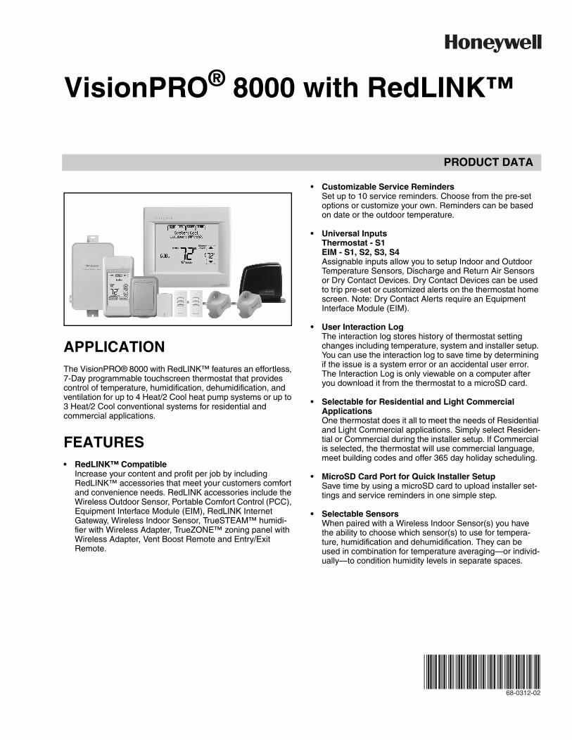
APPLICATIONThe VisionPRO® 8000 with RedLINK™ features an effortless, 7-Day programmable touchscreen thermostat that provides control of temperature, humidification, dehumidification, and ventilation for up to 4 Heat/2 Cool heat pump systems or up to 3 Heat/2 Cool conventional systems for residential and commercial applications.
FEATURES• RedLINK™ Compatible
Increase your content and profit per job by including RedLINK™ accessories that meet your customers comfort and convenience needs. RedLINK accessories include the Wireless Outdoor Sensor, Portable Comfort Control (PCC), Equipment Interface Module (EIM), RedLINK Internet Gateway, Wireless Indoor Sensor, TrueSTEAM™ humidi-fier with Wireless Adapter, TrueZONE™ zoning panel with Wireless Adapter, Vent Boost Remote and Entry/Exit Remote.
• Customizable Service RemindersSet up to 10 service reminders. Choose from the pre-set options or customize your own. Reminders can be based on date or the outdoor temperature.
• Universal InputsThermostat - S1EIM - S1, S2, S3, S4Assignable inputs allow you to setup Indoor and Outdoor Temperature Sensors, Discharge and Return Air Sensors or Dry Contact Devices. Dry Contact Devices can be used to trip pre-set or customized alerts on the thermostat home screen. Note: Dry Contact Alerts require an Equipment Interface Module (EIM).
• User Interaction LogThe interaction log stores history of thermostat setting changes including temperature, system and installer setup. You can use the interaction log to save time by determining if the issue is a system error or an accidental user error. The Interaction Log is only viewable on a computer after you download it from the thermostat to a microSD card.
• Selectable for Residential and Light Commercial ApplicationsOne thermostat does it all to meet the needs of Residential and Light Commercial applications. Simply select Residen-tial or Commercial during the installer setup. If Commercial is selected, the thermostat will use commercial language, meet building codes and offer 365 day holiday scheduling.
• MicroSD Card Port for Quick Installer SetupSave time by using a microSD card to upload installer set-tings and service reminders in one simple step.
• Selectable SensorsWhen paired with a Wireless Indoor Sensor(s) you have the ability to choose which sensor(s) to use for tempera-ture, humidification and dehumidification. They can be used in combination for temperature averaging—or individ-ually—to condition humidity levels in separate spaces.

VISIONPRO® 8000 WITH REDLINK™
68-0312—02 2
ORDERING INFORMATIONWhen purchasing replacement and modernization products from your TRADELINE® wholesaler or distributor, refer to the TRADELINE® Catalog or price sheets for complete ordering number. If you have additional questions, need further information, or would like to comment on our products or services, please write or phone:
1. Your local Honeywell Environmental and Combustion Controls Sales Office (check white pages of your phone directory).2. Honeywell Customer Care
1885 Douglas Drive NorthMinneapolis, Minnesota 55422-4386
3. http://customer.honeywell.com or http://customer.honeywell.caInternational Sales and Service Offices in all principal cities of the world. Manufacturing in Belgium, Canada, China, Czech Republic, Germany, Hungary, Italy, Mexico, Netherlands, United Kingdom, and United States.
CONTENTSApplication ........................................... 1Specifications ...................................... 3Ordering Information ........................... 2System Installation .............................. 6
When Installing this Product... ..................... 6Installing Equipment Interface Module (if used) 8Wiring 24 Vac Common ................................ 8Selecting Discharge and Return Air Temperature Sensor Mounting Locations ......................... 9
Selecting Discharge and Return Air Temperature Sensor Mounting Locations .............................................. 9Selecting Return Air Temperature Sensor Mounting Loca-tion ....................................................................... 9
Selecting Thermostat Location .................... 11Installing Wallplate ........................................ 11Power Optional RedLINK™ Accessories .... 13Linking Thermostat to Equipment Interface Mod-ule (if used) .................................................... 14Linking RedLINK Accessories ..................... 14Mounting Optional Accessories .................. 58Data Logs ....................................................... 73
Alerts Log ............................................................. 73User Interactions Log ........................................... 73
Dry Contact Alerts ........................................ 74Setting the Time/Date ................................... 61Setting the Fan .............................................. 61Setting System Mode .................................... 61
Installer Tests ...................................... 57Using the Equipment Test ............................ 57Using the Wireless Signal Strength Test .... 58
Indoor Air Quality (IAQ) Control ......... 80Humidification ............................................... 80
Set up Humidification ........................................... 80Control Humidification Level ................................ 82
Dehumidification - Residential ..................... 83Set up Dehumidification With Cooling System ..... 83Set up Dehumidification With Whole House Dehumidifier 84Set up Dehumidification Away Mode ................... 86Control Dehumidification Level ............................ 87
Dehumidification - Commercial ................... 87Set up Dehumidification With Cooling System ..... 88
Set up Dehumidification With Dehumidifier .......... 89Control Dehumidification Level ............................. 90
Ventilation ...................................................... 91Set up Ventilation ................................................. 92
IAQ Reminders ..................................... 96Customizable Reminders ................... 96MicroSD card ....................................... 100Commercial Features .......................... 102
Preset Energy-Saving Schedules ......................... 62Advanced Features ....................................... 71
Adaptive Intelligent Recovery (residential use only) 71Compressor Protection ......................................... 71
Heat Pump and Backup Heat Operation 78Portable Comfort Control ................... 111Remote Indoor Sensors ...................... 112
Ramp Rates (Commercial Use) .................... 105Remote Setback (Commercial Use) ............. 105Economizer and Time of Day (TOD) Operation 106Pre-Occupancy Purge ................................... 107Staging Control ............................................. 76
Optional Accessories .......................... 110Troubleshooting .................................. 140Wiring ................................................... 117
EIM Wiring Diagrams .................................... 120Geothermal Radiant Heat ............................. 78Wiring IAQ Equipment or a Heat/Cool Stage to the Universal Terminals ...................................... 129Economizer Module Wiring Diagrams ......... 132Wiring C7089U1006 Outdoor Sensor .......... 134Wiring guide — Wired Indoor Sensors ........ 135
Regulatory Information ....................... 140

VISIONPRO® 8000 WITH REDLINK™
3 68-0312—02
SPECIFICATIONSThermostat Description:
Electrical Ratings for: the Equipment Interface Module and VisionPRO Thermostats
NOTE: To find what terminals are available on the Equip-ment Interface Module and the VisionPRO Thermo-stats, see "Terminal Designations" below the table.
Terminal Designations:— Equipment Interface Module: R, RC, RH, C, W-O/B,
W2-AUX 1, W3-AUX 2, Y, Y2, G, A-L/A, U1 U1, U2 U2,U3 U3, S1 S1, S2 S2, S3 S3, S4 S4, A, B, C, D
— TH8321 Thermostat: R, RC, C, W-O/B, W2-AUX/E, Y, Y2, G, A-L/A, K, U1 U1, S1 S1
— TH8320 Thermostat: R, RC, C, W-O/B, W2-AUX/E, Y, Y2, G, A-L/A, K, S1 S1
— TH8110 Thermostat: R, RC, C, W-O/B, Y, G, K, S1 S1
Power Consumption of TH8321/TH8320/TH8110:Backlight on: 1.44 VABacklight off: 1.32 VA
RedLINK Communication:Frequency: 900 Mhz frequency rangeRe-Sync Time: RedLINK devices re-establish communication
within 6 minutes after AC power resumes.
Temperature Setting Range:Heating: 40 to 90 °F (4.5 to 32 °C).Cooling: 50 to 99 °F (10 to 37 °C).
Temperature Sensor Accuracy: ± 1.5 F at 70 F (0.75 C at 21.0 C)
Humidification Setting Range:10% to 60% RH.
Dehumidification Setting Range:40% to 80% RH.
Humidity Display Range:0% to 99%.
Humidity Sensor Accuracy: ± 5% RH from 30% to 50% RH at 75 F.
Cool Indication:VisionPRO® 8000 with RedLINK™ displays “Cool On” when
the thermostat turns the cooling on.
Heat Indication:VisionPRO® 8000 with RedLINK™ displays “Heat On” when
the thermostat turns the heating on.
Auxiliary Heat Indication:VisionPRO® 8000 with RedLINK™ displays “Aux Heat On”
when the thermostat turns the auxiliary heat on.
Interstage Differential:Comfort: The thermostat keeps the indoor temperature within 1
degree of the setpoint (droop less control). The thermostat turns on stage 2 when the capacity on stage 1 reaches 90%.
When the interstage differential is set to 1.0 or higher, the ther-mostat stages the equipment based on how far the indoor temperature is from the setpoint (ISU 303 to 309). See page 27 for more information.
Clock Accuracy: 1 minute per month at 77 °F (25 °C). ± 2 minutes per month over the operating ambient temperature range.
Mounting Means:Thermostat mounts directly on the wall in the living space
using mounting screws and anchors provided. Fits a hori-zontal 2 x 4 in. junction box.
Equipment Interface Module (EIM) mounts on HVAC equip-ment or on a wall in the equipment room.
Fig. 1. Dimensions of thermostat in in. (mm).
Feature Description
Powering method • Common wire or battery
System types (up to 4 heat/2 cool heat pump and up to 3 heat/2 cool conventional)
• Gas, oil or electric heat with air conditioning
• Warm air, hot water, high-efficiency furnaces, heat pumps, steam and gravity
• Cool only
Changeover Manual or Auto changeover selectable
System setting Em Heat-Heat-Off-Cool-Auto
Fan setting Auto-On-Circ-Follow Schedule
Terminal Voltage
(50/60 Hz) Max. Current
Rating
W - O/B 18 to 30 VAC and 750 mVDC
1.00A
Y (cooling) 18 to 30 VAC 1.00A
G (fan) 18 to 30 VAC 0.50A
W2 - Aux 1 (heating) 18 to 30 VAC 0.60A
W3 - Aux 2 (heating) 18 to 30 VAC 0.60A
Y2 (cooling) 18 to 30 VAC 0.60A
A-L/A (Output) 18 to 30 VAC 1.00A
U1, U1U2, U2U3, U3
30 VAC max. 0.50A
M34521
4-15/16 (126)
4-5/8(118)
1-1/8 (29)
3-5/16 (84)

VISIONPRO® 8000 WITH REDLINK™
68-0312—02 4
Fig. 2. Dimensions of VisionPRO cover plate in in. (mm).
Fig. 3. Dimensions of Equipment Interface Module in in. (mm).
M34258
25/32(20)
6-5/32(156)
1-1/2(38)
5-3/4(146)
M33331
4-53/64 (123)
8-7/8(225)
9-11/32(237)
1-19/32(41)
Product Part Number
Operating Ambient
TemperatureOperating
Relative HumidityShipping
TemperaturePhysical Dimensions in in.
(mm) Color(s)
Thermostat TH8321R1001TH8320R1003TH8110R1008
32 to 120 °F(0 to 48.9 °C)
5% to 90% Non-Condensing
-20 to 120 °F(-28.9 to 48.9 °C)
4-15/16 x 4-5/8 x 1-1/8 (126 x 118 x 29)
Arctic White
Equipment Interface Module
YTHM5421R1010*THM5421R1021
-40 to 165 °F(-40 to 73.9 °C)
5% to 95%Non-Condensing
-20 to 165 °F(-28.9 to 73.9 °C)
9-11/32 x 4-53/64 x 1-19/32(237 x 123 x 41)
Gray
Wireless Adapter(For TrueZONE, TrueSTEAM or extend wireless range of EIM)
THM4000R1000 -40 to 165 °F(-40 to 73.9 °C)
5% to 95% Non-Condensing
-20 to 165 °F(-28.9 to 73.9 °C)
5-9/16 x 4-3/8 x 1-1/4 (141 x 112 x 32)
Gray
RedLINK Internet Gateway
THM6000R1002 32 to 120 °F(0 to 48.9 °C)
5% to 95%Non-Condensing
-20 to 120 °F(-28.9 to 48.9 °C)
6 x 4-7/8 x 2-1/2(152 x 124 x 64)
Black
Portable Comfort Control
REM5000R1001 32 to 120 °F(0 to 48.9 °C)
5% to 90%Non-Condensing
-20 to 120 °F(-28.9 to 48.9 °C)
6-1/4 x 3-1/8 x 1-5/8(158 x 80 x 38)
Arctic White, Gray
Wireless Entry/Exit Remote
REM1000R1003 32 to 120 °F(0 to 48.9 °C)
5% to 90%Non-Condensing
-20 to 120 °F(-28.9 to 48.9 °C)
3-15/16 x 1-15/16 x 5/8(101 x 50 x 16)
Arctic White
Wireless Vent and Filter Boost Remote
HVC20A1000 32 to 120 °F(0 to 48.9 °C)
5% to 90%Non-Condensing
-20 to 120 °F(-28.9 to 48.9 °C)
3-15/16 x 1-15/16 x 5/8 (101 x 50 x 16)
Arctic White
Wireless Outdoor Sensor
C7089R1013 -40 to 140 °F(-40 to 60 °C)
0% to 100%Condensing
-40 to 120 °F(-40 to 48.9 °C)
5 x 3-1/2 x 1-11/16 (127 x 89 x 43)
Gray
Wireless Indoor Sensor C7189R1004 0 to 120 °F(-17.8 to 48.9 °C)
For optimal Battery Life:35 to 114 °F(1.7 to 45.6 °C)
5% to 90%Non-Condensing
-20 to 120 °F(-28.9 to 48.9 °C)
2-7/8 x 1-7/8 x 15/16 (74 x 48 x 24)
Arctic White
Wired Outdoor Sensor(10K ohm Negative Temperature Coefficient)
C7089U1006 -40 to 120 °F(-40 to 48.9 °C)
5% to 95%Non-Condensing
-40 to 130 °F(-40 to 54.4 °C)
1-1/2 (38) - -
Wired Wall Mount Indoor Sensor(10K ohm Negative Temperature Coefficient)
C7189U1005 45 to 88 °F(7 to 32 °C)
5% to 95%Non-Condensing
-20 to 120 °F(-28.9 to 48.9 °C)
2-9/32 x 1-1/2 x 11/16(58 x 38 x 18)
Premier White
VISIONPRO® 8000 WITH REDLINK™
5 68-0312—02
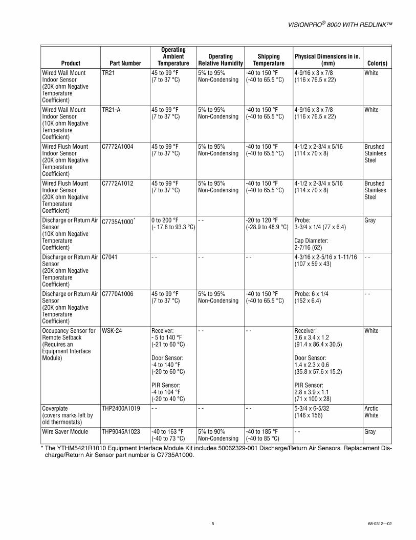
* The YTHM5421R1010 Equipment Interface Module Kit includes 50062329-001 Discharge/Return Air Sensors. Replacement Dis-charge/Return Air Sensor part number is C7735A1000.
Wired Wall Mount Indoor Sensor(20K ohm Negative Temperature Coefficient)
TR21 45 to 99 °F(7 to 37 °C)
5% to 95%Non-Condensing
-40 to 150 °F(-40 to 65.5 °C)
4-9/16 x 3 x 7/8(116 x 76.5 x 22)
White
Wired Wall Mount Indoor Sensor(10K ohm Negative Temperature Coefficient)
TR21-A 45 to 99 °F(7 to 37 °C)
5% to 95%Non-Condensing
-40 to 150 °F(-40 to 65.5 °C)
4-9/16 x 3 x 7/8(116 x 76.5 x 22)
White
Wired Flush Mount Indoor Sensor(20K ohm Negative Temperature Coefficient)
C7772A1004 45 to 99 °F(7 to 37 °C)
5% to 95%Non-Condensing
-40 to 150 °F(-40 to 65.5 °C)
4-1/2 x 2-3/4 x 5/16(114 x 70 x 8)
Brushed Stainless Steel
Wired Flush Mount Indoor Sensor(20K ohm Negative Temperature Coefficient)
C7772A1012 45 to 99 °F(7 to 37 °C)
5% to 95%Non-Condensing
-40 to 150 °F(-40 to 65.5 °C)
4-1/2 x 2-3/4 x 5/16(114 x 70 x 8)
Brushed Stainless Steel
Discharge or Return Air Sensor(10K ohm Negative Temperature Coefficient)
C7735A1000* 0 to 200 °F(- 17.8 to 93.3 °C)
- - -20 to 120 °F(-28.9 to 48.9 °C)
Probe: 3-3/4 x 1/4 (77 x 6.4)
Cap Diameter: 2-7/16 (62)
Gray
Discharge or Return Air Sensor(20K ohm Negative Temperature Coefficient)
C7041 - - - - - - 4-3/16 x 2-5/16 x 1-11/16(107 x 59 x 43)
- -
Discharge or Return Air Sensor(20K ohm Negative Temperature Coefficient)
C7770A1006 45 to 99 °F(7 to 37 °C)
5% to 95%Non-Condensing
-40 to 150 °F(-40 to 65.5 °C)
Probe: 6 x 1/4(152 x 6.4)
- -
Occupancy Sensor for Remote Setback(Requires an Equipment Interface Module)
WSK-24 Receiver: - 5 to 140 °F(-21 to 60 °C)
Door Sensor:-4 to 140 °F(-20 to 60 °C)
PIR Sensor:-4 to 104 °F(-20 to 40 °C)
- - - - Receiver: 3.6 x 3.4 x 1.2(91.4 x 86.4 x 30.5)
Door Sensor:1.4 x 2.3 x 0.6(35.8 x 57.6 x 15.2)
PIR Sensor:2.8 x 3.9 x 1.1(71 x 100 x 28)
White
Coverplate(covers marks left by old thermostats)
THP2400A1019 - - - - - - 5-3/4 x 6-5/32(146 x 156)
Arctic White
Wire Saver Module THP9045A1023 -40 to 163 °F(-40 to 73 °C)
5% to 90%Non-Condensing
-40 to 185 °F(-40 to 85 °C)
- - Gray
Product Part Number
Operating Ambient
TemperatureOperating
Relative HumidityShipping
TemperaturePhysical Dimensions in in.
(mm) Color(s)

VISIONPRO® 8000 WITH REDLINK™
68-0312—02 6
SYSTEM INSTALLATION
When Installing this Product...1. Read these instructions carefully. Failure to follow the
instructions can damage the product or cause a hazard-ous condition.
2. Check the ratings given in the instructions to make sure the product is suitable for your application.
3. Installer must be a trained, experienced service technician.
4. After completing installation, use these instructions to verify the product operation.
Finding Your Password (Date Code)You will need the thermostat password to:• Add or remove RedLINK accessories• Make changes to Installer Setup• Perform an Installer Test• Reset Thermostat to Factory Default Settings
The password (date code) is located on the back of the thermostat (see Fig. 4)
Fig. 4. Finding thermostat password.
You can also find the password (date code) by pressing MENU, selecting Dealer Information and then scrolling down to see the Date Code.
Resid
entia
l/Rés
ident
iel1-
800-
468-
1502
ht
tp://
your
hom
e.hon
eywe
ll.com
Com
mer
cial/C
omm
ercia
le1-
888-
245-
1051
http
://cu
stom
er.ho
neyw
ell.co
mHo
neyw
ell, G
olden
Valle
y, MN
5542
2
RoHs CompliantConformité RoHsAssembled in MexicoAssemblé au Mexique
TH83
21R1
001
1
1324
Resd
enta
/Rés
dent
e1-
800-
468
1502
ht
tp//y
ouho
meh
oney
we
com
Com
mer
ca/C
omm
eca
e1-
888-
245
1051
http
//cu
tom
erho
neyw
eco
mHo
neyw
e G
ode
n Va
ey M
N 55
422
RoHs CompliantConform té RoHsA sembled in Me ico
mblé au Mex que
TH83
21R1
001
1
1324
Password (Date Code)
VISIONPRO® 8000 WITH REDLINK™
7 68-0312—02
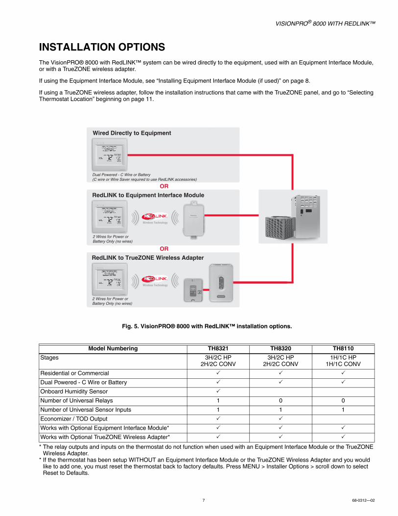
INSTALLATION OPTIONSThe VisionPRO® 8000 with RedLINK™ system can be wired directly to the equipment, used with an Equipment Interface Module, or with a TrueZONE wireless adapter.
If using the Equipment Interface Module, see “Installing Equipment Interface Module (if used)” on page 8.
If using a TrueZONE wireless adapter, follow the installation instructions that came with the TrueZONE panel, and go to “Selecting Thermostat Location” beginning on page 11.
Fig. 5. VisionPRO® 8000 with RedLINK™ installation options.
* The relay outputs and inputs on the thermostat do not function when used with an Equipment Interface Module or the TrueZONE Wireless Adapter.
* If the thermostat has been setup WITHOUT an Equipment Interface Module or the TrueZONE Wireless Adapter and you would like to add one, you must reset the thermostat back to factory defaults. Press MENU > Installer Options > scroll down to select Reset to Defaults.
Model Numbering TH8321 TH8320 TH8110
Stages 3H/2C HP2H/2C CONV
3H/2C HP2H/2C CONV
1H/1C HP1H/1C CONV
Residential or Commercial
Dual Powered - C Wire or Battery
Onboard Humidity Sensor
Number of Universal Relays 1 0 0
Number of Universal Sensor Inputs 1 1 1
Economizer / TOD Output
Works with Optional Equipment Interface Module*
Works with Optional TrueZONE Wireless Adapter*
M
M
OR
OR
Wired Directly to Equipment
2 Wires for Power orBattery Only (no wires)
2 Wires for Power orBattery Only (no wires)
Dual Powered - C Wire or Battery(C wire or Wire Saver required to use RedLINK accessories)
RedLINK to Equipment Interface Module
RedLINK to TrueZONE Wireless Adapter

VISIONPRO® 8000 WITH REDLINK™
68-0312—02 8
Guidelines for Installing RedLINK Devices— When installing more than one Thermostat and Equipment
Interface Module, mount the Equipment Interface Modules at least 2 feet apart for best RedLINK performance. No minimum distance is required between the Thermostats if the Thermostat is linked to an Equipment Interface Module.
— When the Thermostat is wired directly to the equipment (No Equipment Interface Module and No TrueZONE Wireless Adapter), mount the Thermostats at least 2 feet apart for best RedLINK performance.
— To determine if a RedLINK device will communicate properly in the installed location, during the connection process, press and quickly release the connect button on the RedLINK device at the desired mounting location. If the RedLINK device connects, then it will work reliably during normal operation. If the RedLINK device does NOT connect, try a new location. During the connection process, the signal is sent at low power and during normal operation the signal is sent at high power.
— To connect a RedLINK device, make sure to press and quickly release the connect button on the RedLINK device. Press and holding the connect button down too long will not allow the device to connect.
— If you link the Thermostat to the TrueZONE Wireless Adapter, you will NOT be able to do the following: control humidification, dehumidification or ventilation, setup a program schedule remotely from a computer, smart phone or tablet, work with the Wireless Indoor Sensor, Entry / Exit Remote or the Vent and Filter Boost Remote. To use these features, wire the Thermostat directly to the zone panel or use an Equipment Interface Module.
— If you are using a RedLINK device from a previous installation, you must reset the device first before you re-connect it to the new Thermostat/Equipment Interface Module. See page 116 for more information.
Installing Equipment Interface Module (if used)If no Equipment Interface Module is used, skip to “Selecting Thermostat Location” beginning on page 11.
NOTE: If an EIM is mounted inside a metal cabinet, such as a commercial rooftop unit, it is recommended to use a THM4000R1000 Wireless Adapter for extended wireless range. Mount the Wireless Adapter outside the metal cabinet and connect to the ABCD terminals at the EIM. The Wireless Adapter functions as a remote antenna for the EIM. After it is wired to the EIM, it automatically takes over as the antenna for RedLINK communi-cation. For best RedLINK performance, avoid mounting the Wireless Adapter above the roof deck or outside the exterior walls.
NOTE: If you install more than one thermostat and EIM, the EIMs must be at least 2 feet apart for best RedLINK performance.
CAUTIONElectrical Hazard.Can cause electrical shock or equipment damage.Disconnect power before wiring.
The Equipment Interface Module (EIM) can be mounted vertically on the HVAC equipment or on a wall in the equipment room.
1. Mount the EIM near the HVAC equipment, or on the equipment itself. Use screws & anchors as appropriate for the mounting surface.
2. To wire the EIM, strip 1/4” insulation, then insert wires (see Fig. 7). For wiring diagrams, see “Wiring” beginning on page 117.
Fig. 6. THM4000R1000 Wireless Adapter wired to the EIM.
Fig. 7.
NOTE: Link EIM to thermostat BEFORE linking any RedLINK accessories. See “Linking RedLINK Accessories” on page 14.
3. If you are installing discharge and return air sensors, see “Selecting Discharge and Return Air Temperature Sen-sor Mounting Locations” beginning on page 9).
Wiring 24 Vac Common• Single-Transformer System—Connect the common side of
the transformer to the C screw terminal of the EIM. Leave the metal jumper wires in place between R, RC, and RH.
• Two-Transformer System—Connect the common side of the cooling transformer to the C screw terminal of the EIM. Remove the metal jumper wire between RC and RH. Connect the hot side of heating transformer to RH and leave the jumper wire between R and RC and connect the hot side of cooling transformer to R or RC.
EIM
A
B
C
D
WIRELESSADAPTER
CONNECT
POW R
THM4000R
CONN CTED
W RELESS SETUP
CONNECT
CONNECTED
MCR34049A
R
C
Y
Y2G
W O/B
W2
AUX1
W3
AUX2
A L/A

VISIONPRO® 8000 WITH REDLINK™
9 68-0312—02
Selecting Discharge and Return Air Temperature Sensor Mounting LocationsRefer to the guidelines below and Fig. 8–12 for mounting locations of the Discharge and Return Air Temperature Sensors.
Selecting Discharge Air Temperature Sensor Mounting Location
1. Mount the Discharge Air Temperature Sensor on the supply duct in a location where the air is mixed well. Mount the Discharge Air Temperature Sensor out of sight of the A-Coil/Heat Exchanger when possible. See Fig. 8.
2. When possible, mount the Discharge Air Temperature Sensor upstream of a Steam Humidifier, a Fan Powered Humidifier or a Dehumidifier that is ducted to the supply. See Fig. 9–10.
3. If space does not allow a Discharge Air Temperature Sensor upstream of a Steam Humidifier or Fan Powered Humidifier, mount the Discharge Air Temperature Sensor downstream of the Humidifier. See Fig. 9.
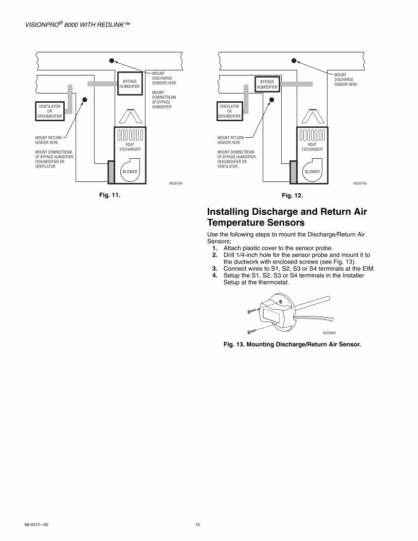
4. If a Bypass Humidifier is installed, mount the Discharge Air Temperature Sensor downstream of the Bypass Humidifier. See Fig. 11–12.
Selecting Return Air Temperature Sensor Mounting Location
1. Install the Return Air Temperature Sensor on the return duct in a location where the air is mixed well. Mount the Return Air Temperature Sensor downstream of a Bypass Humidifier, Dehumidifier or Ventilator. See Fig. 8–12.
Fig. 8.
Fig. 9.
Fig. 10.
MOUNT DISCHARGESENSOR HERE
M33074
HEATEXCHANGER
BLOWER
VENTILATOROR
DEHUMIDIFIER
MOUNT RETURNSENSOR HERE
DOWNSTREAM OF VENTILATOR OR DEHUMIDIFIER
A COIL
M34806
HEATEXCHANGER
BLOWER
STEAM ORFAN
POWEREDHUMIDIFIER
ALTERNATE MOUNTING LOCATIONFOR DISCHARGE SENSOR.
MOUNT RETURNSENSOR HERE
DOWNSTREAM OF VENTILATOR OR DEHUMIDIFIER
MOUNT DISCHARGESENSOR HERE
ABOVE CENTEROF A COIL
UPSTREAM OFSTEAM OR FAN POWERED HUMIDIFIER
VENTILATOROR
DEHUMIDIFIER
M34807
HEATEXCHANGER
BLOWER
MOUNT RETURNSENSOR HERE
DOWNSTREAM OF DEHUMIDIFIER
ALTERNATE MOUNTING LOCATION FOR DISCHARGE SENSOR.
MOUNT DISCHARGESENSOR HERE
ABOVE CENTEROF A COIL
UPSTREAM OFDEHUMIDIFIER
DEHUMIDIFIER
VISIONPRO® 8000 WITH REDLINK™
68-0312—02 10
Fig. 11. Fig. 12.
Installing Discharge and Return Air Temperature SensorsUse the following steps to mount the Discharge/Return Air Sensors:
1. Attach plastic cover to the sensor probe.2. Drill 1/4-inch hole for the sensor probe and mount it to
the ductwork with enclosed screws (see Fig. 13).3. Connect wires to S1, S2, S3 or S4 terminals at the EIM.4. Setup the S1, S2, S3 or S4 terminals in the Installer
Setup at the thermostat.
Fig. 13. Mounting Discharge/Return Air Sensor.
MOUNT RETURN SENSOR HERE
MOUNT DOWNSTREAM OF BYPASS HUMIDIFIER, DEHUMIDIFIER OR VENTILATOR
HEATEXCHANGER
BLOWER
VENTILATOROR
DEHUMIDIFIER
MOUNT DISCHARGESENSOR HERE
MOUNT DOWNSTREAM OF BYPASS HUMIDIFIER
BYPASSHUMIDIFIER
M33078A
MOUNT RETURN SENSOR HERE
MOUNT DOWNSTREAM OF BYPASS HUMIDIFIER, DEHUMIDIFIER OR VENTILATOR
HEATEXCHANGER
BLOWER
VENTILATOROR
DEHUMIDIFIER
MOUNT DISCHARGE SENSOR HEREBYPASS
HUMIDIFIER
M33079A
M32995

VISIONPRO® 8000 WITH REDLINK™
11 68-0312—02
Selecting Thermostat LocationInstall the thermostat about 5 ft. (1.5m) above the floor in an area with good air circulation at average temperature. See Fig. 14.
Fig. 14. Selecting thermostat location.
Do not install the thermostat where it can be affected by:— Drafts or dead spots behind doors and in corners.— Hot or cold air from ducts.— Radiant heat from sun or appliances.— Concealed pipes and chimneys.— Unheated (uncooled) areas such as an outside wall behind
the thermostat.
Installing Wallplate
CAUTIONElectrical Hazard.Can cause electrical shock or equipment damage.Disconnect power before wiring.
NOTE: For best RedLINK performance, mount thermo-stats at least 2 feet apart.
The thermostat can be mounted horizontally on the wall or on a 4 in. x 2 in. (101.6 mm x 50.8 mm) wiring box.
1. Press button on top and pull to remove the wallplate.
Fig. 15. Separate wallplate from thermostat.
2. Position and level the wallplate (for appearance only).3. Use a pencil to mark the mounting holes.4. Remove the wallplate from the wall and, if drywall, drill
two 3/16-in. holes in the wall, as marked. For firmer material such as plaster, drill two 7/32-in. holes. Gently tap anchors (provided) into the drilled holes until flush with the wall.
5. Position the wallplate over the holes, pulling wires through the wiring opening. See Fig. 16.
6. Insert the mounting screws into the holes and tighten.
Fig. 16. Mounting wallplate.
Installing VisionPRO® 8000 with RedLINK™
Connect Power1. Insert supplied AA alkaline batteries for primary or
backup power.
Fig. 17. Insert AA batteries.
NOTE: When the thermostat is NOT used with the Equip-ment Interface Module or the TrueZONE Wireless Adapter, a C wire is required for RedLINK.
5 FEET[1.5 METERS]
YESNO
NO
NO
M19925
S1
S1
W
Y
G
W2
Y2
C
K
RC
R
U1
U1
U2
U2
S1
S1
O/B
Y
GAUX
E
Y2L A
VISIONPRO® 8000 WITH REDLINK™
68-0312—02 12
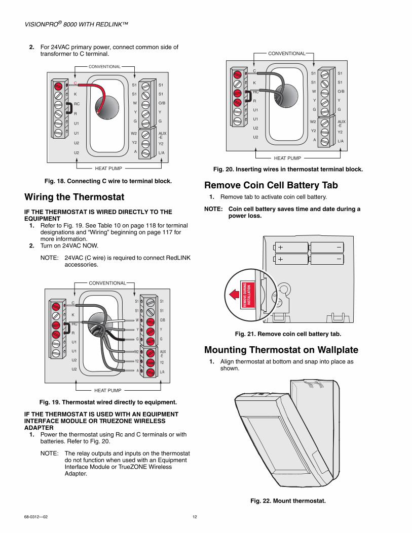
2. For 24VAC primary power, connect common side of transformer to C terminal.
Fig. 18. Connecting C wire to terminal block.
Wiring the ThermostatIF THE THERMOSTAT IS WIRED DIRECTLY TO THE EQUIPMENT
1. Refer to Fig. 19. See Table 10 on page 118 for terminal designations and “Wiring” beginning on page 117 for more information.
2. Turn on 24VAC NOW.
NOTE: 24VAC (C wire) is required to connect RedLINK accessories.
Fig. 19. Thermostat wired directly to equipment.
IF THE THERMOSTAT IS USED WITH AN EQUIPMENT INTERFACE MODULE OR TRUEZONE WIRELESS ADAPTER
1. Power the thermostat using Rc and C terminals or with batteries. Refer to Fig. 20.
NOTE: The relay outputs and inputs on the thermostat do not function when used with an Equipment Interface Module or TrueZONE Wireless Adapter.
Fig. 20. Inserting wires in thermostat terminal block.
Remove Coin Cell Battery Tab1. Remove tab to activate coin cell battery.
NOTE: Coin cell battery saves time and date during a power loss.
Fig. 21. Remove coin cell battery tab.
Mounting Thermostat on Wallplate1. Align thermostat at bottom and snap into place as
shown.
Fig. 22. Mount thermostat.
S1
S1
W
Y
G
W2
Y2
A
S1
S1
O/B
Y
G
AUX-E
Y2
L/A
K
RC
R
U1
U1
U2
U2
C
CONVENTIONAL
HEAT PUMP
S1
S1
W
Y
G
W2
Y2
A
S1
S1
O/B
Y
G
AUX-E
Y2
L/A
K
RC
R
U1
U1
U2
U2
C
CONVENTIONAL
HEAT PUMP
S1
S1
W
Y
G
W2
Y2
A
S1
S1
O/B
Y
G
AUX-E
Y2
L/A
K
RC
R
U1
U1
U2
U2
C
CONVENTIONAL
HEAT PUMP
REM
OVE
DURI
NGIN
STAL
LATI
ON

VISIONPRO® 8000 WITH REDLINK™
13 68-0312—02
POWER OPTIONAL REDLINK™ ACCESSORIES
Outdoor air sensor1. Install 2 fresh AA lithium batteries.
Fig. 23.
Portable Comfort Control1. Install 3 fresh AA alkaline batteries.
Fig. 24.
Indoor air sensor1. Install 2 fresh AAA alkaline batteries.
Fig. 25.
RedLINK™ Internet Gateway1. Connect power cord to an electrical outlet not controlled
by a wall switch.2. Connect ethernet cable to router and the RedLINK Inter-
net Gateway.
Fig. 26.
TrueSTEAM1. Wire and power TrueSTEAM.2. Connect the ABCD terminals between TrueSTEAM and
the THM4000 Wireless Adapter.3. Adjust the DIP Switches on TrueSTEAM as follows when
using the Wireless Adapter:• DIP3: UP• DIP4: UP• DIP5: DOWN
Fig. 27. Powering TrueSTEAM wireless adapter.
Entry/Exit Remote or Vent Boost Remote1. Remove the cover.2. Insert the CR2450 coin cell battery (included) into the
slot at the bottom of the remote. See polarity marking on the remote.
Fig. 28. Installing Entry/Exit Remote or Vent Boost Remote battery.
3. The LED will briefly flash green. If it flashes red, battery is not good.
MCR32937
MCR32939
MCR32938
M32940
THM4000R1000
TrueSTEAM
MCR31476
65432
ON
OFF
1
MCR33269

VISIONPRO® 8000 WITH REDLINK™
68-0312—02 14
PERFORMING INITIAL SETUPNOTE: If the thermostat is wired directly to the equip-
ment, 24 VAC (C wire) is required to connect RedLINK accessories. Turn on 24 VAC before per-forming the initial setup.
Initial setup options define the type of system you are installing:• Residential or commercial• Non-zoned or zoned• Used with or without an Equipment Interface Module
(THM5421)• Used with or without the TrueZONE Wireless Adapter
(THM4000)
1. Follow prompts on the screen to select the appropriate options.
Fig. 29. Select application (residential or commercial).
NOTE: If you are connecting the thermostat to the True-ZONE Wireless Adapter (THM4000), refer to the TrueZONE instructions to link the thermostat and RedLINK accessories.
Linking Thermostat to Equipment Interface Module (if used)
1. In thermostat setup, when you are prompted to answer TSTAT CONTROLS AN EQUIP. MODULE: select yes, then press Next.
Fig. 30.
2. Press and quickly release the CONNECT button on the EIM. Make sure the “Connected” light is flashing green.
Fig. 31. EIM CONNECT button.
NOTE: If the “Connected” light does NOT flash green, another system may be in the listening mode. Please exit the listening mode at the other sys-tem and then try again.Green Flashing: In Listening Mode - system is ready to add RedLINK devices.Green Steady: RedLINK devices are communi-cating.Red: RedLINK device(s) are NOT communicat-ing. Check EIM and RedLINK devices.
3. While the “Connected” light is flashing green on the EIM, press Next on the thermostat. After a short delay, the screen will show the thermostat is connected.
Fig. 32.
Fig. 33.
4. Press Next, as directed on screen, to link RedLINK accessories.
Linking RedLINK Accessories1. When you see the prompt Connect RedLINK Accesso-
ries?, touch No or Yes.a. If you select No, continue to step 5.b. If you select Yes, you will be prompted to Press Con-
nect on New Accessories. Continue to step 2.
Fig. 34. Connect RedLINK accessories.
NOTE: Accessories must be at least 2 feet away from the thermostat or EIM during the linking process.
APPLICATIONresidential
CONNECT
CONNECTED
MCR33970
Connect RedLINK Accessories?

VISIONPRO® 8000 WITH REDLINK™
15 68-0312—02
2. While the Press Connect message is displayed (listening mode), press and quickly release the CONNECT button on each new RedLINK accessory.
NOTE: For locations of CONNECT buttons on RedLINK accessories, see “Locating the Con-nect Buttons on RedLINK Accessories” begin-ning on page 16.
Fig. 35. Thermostat in listening mode.
3. After a short delay (up to 15 seconds), check thermostat to confirm the connection of each RedLINK accessory. Touch or to review the list.
Fig. 36. Outdoor sensor added.
4. Touch Done at the thermostat after all new RedLINK accessories are connected.
NOTE: Thermostat displays a countdown timer while in the listening mode. If it detects no activity for 15 minutes, it exits listening mode.
Completing Initial Setup5. Finish the setup by selecting the desired options. Touch
Done after you select the last option you want to change.
Fig. 37. Thermostat type.
The thermostat now displays its Home screen and the thermostat setup is complete.
Fig. 38. Thermostat home screen.
Adding RedLINK Accessories to the ThermostatIf you want to add RedLINK accessories after the thermostat has been setup, follow these steps.
1. Touch Menu.2. Select Installer Options.
Fig. 39.
3. Enter password (date code) and touch Done. See “Find-ing Your Password (Date Code) to Access Installer Options” beginning on page 19 for more information.
Fig. 40.
Press Connect onNew Accessories.
MCR33972
Outdoor Sensorhas been added
M34150
THERMOSTAT TYPEprogrammable
M33985
MCR33976
Installer Options
MCR33977
Enter password0 0 0 0
VISIONPRO® 8000 WITH REDLINK™
68-0312—02 16
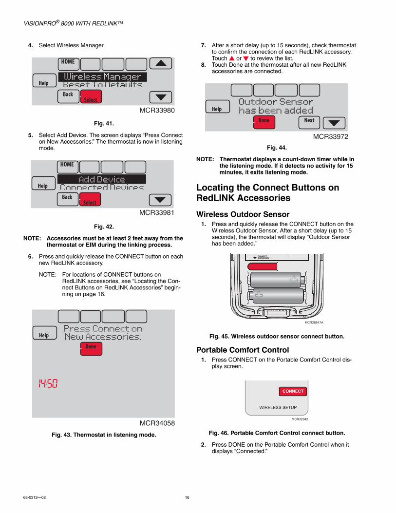
4. Select Wireless Manager.
Fig. 41.
5. Select Add Device. The screen displays “Press Connect on New Accessories.” The thermostat is now in listening mode.
Fig. 42.
NOTE: Accessories must be at least 2 feet away from the thermostat or EIM during the linking process.
6. Press and quickly release the CONNECT button on each new RedLINK accessory.
NOTE: For locations of CONNECT buttons on RedLINK accessories, see “Locating the Con-nect Buttons on RedLINK Accessories” begin-ning on page 16.
Fig. 43. Thermostat in listening mode.
7. After a short delay (up to 15 seconds), check thermostat to confirm the connection of each RedLINK accessory. Touch or to review the list.
8. Touch Done at the thermostat after all new RedLINK accessories are connected.
Fig. 44.
NOTE: Thermostat displays a count-down timer while in the listening mode. If it detects no activity for 15 minutes, it exits listening mode.
Locating the Connect Buttons on RedLINK Accessories
Wireless Outdoor Sensor1. Press and quickly release the CONNECT button on the
Wireless Outdoor Sensor. After a short delay (up to 15 seconds), the thermostat will display “Outdoor Sensor has been added.”
Fig. 45. Wireless outdoor sensor connect button.
Portable Comfort Control1. Press CONNECT on the Portable Comfort Control dis-
play screen.
Fig. 46. Portable Comfort Control connect button.
2. Press DONE on the Portable Comfort Control when it displays “Connected.”
MCR33980
Wireless ManagerReset To Defaults
MCR33981
Add DeviceConnected Devices
MCR34058
Press Connect onNew Accessories.
MCR33972
Outdoor Sensorhas been added
MCR28847A
MCR32942
CONNECT
WIRELESS SETUP
VISIONPRO® 8000 WITH REDLINK™
17 68-0312—02
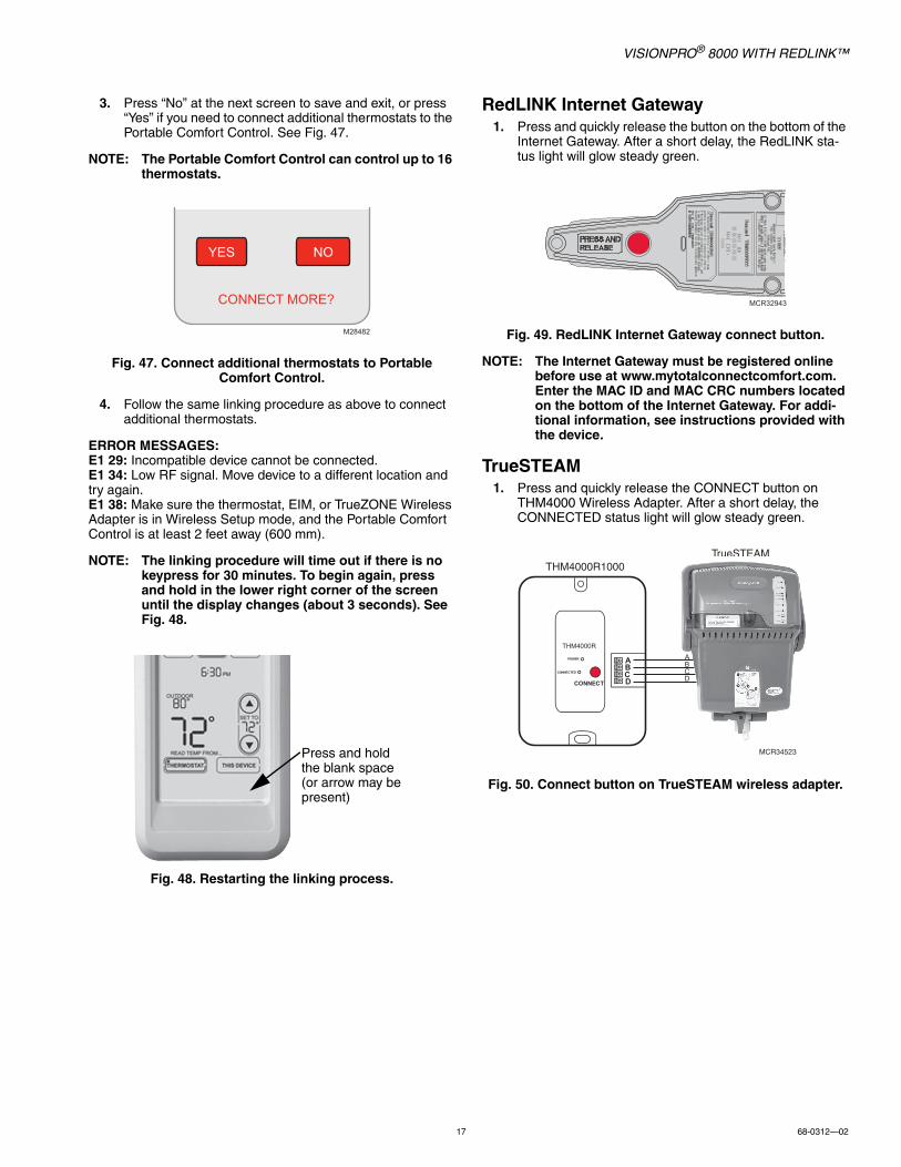
3. Press “No” at the next screen to save and exit, or press “Yes” if you need to connect additional thermostats to the Portable Comfort Control. See Fig. 47.
NOTE: The Portable Comfort Control can control up to 16 thermostats.
Fig. 47. Connect additional thermostats to Portable Comfort Control.
4. Follow the same linking procedure as above to connect additional thermostats.
ERROR MESSAGES:E1 29: Incompatible device cannot be connected.E1 34: Low RF signal. Move device to a different location and try again.E1 38: Make sure the thermostat, EIM, or TrueZONE Wireless Adapter is in Wireless Setup mode, and the Portable Comfort Control is at least 2 feet away (600 mm).
NOTE: The linking procedure will time out if there is no keypress for 30 minutes. To begin again, press and hold in the lower right corner of the screen until the display changes (about 3 seconds). See Fig. 48.
Fig. 48. Restarting the linking process.
RedLINK Internet Gateway1. Press and quickly release the button on the bottom of the
Internet Gateway. After a short delay, the RedLINK sta-tus light will glow steady green.
Fig. 49. RedLINK Internet Gateway connect button.
NOTE: The Internet Gateway must be registered online before use at www.mytotalconnectcomfort.com. Enter the MAC ID and MAC CRC numbers located on the bottom of the Internet Gateway. For addi-tional information, see instructions provided with the device.
TrueSTEAM1. Press and quickly release the CONNECT button on
THM4000 Wireless Adapter. After a short delay, the CONNECTED status light will glow steady green.
Fig. 50. Connect button on TrueSTEAM wireless adapter.
NOYES
CONNECT MORE?
M28482
Press and hold the blank space (or arrow may be present)
MCR32943
THM4000R1000TrueSTEAM
MCR34523
VISIONPRO® 8000 WITH REDLINK™
68-0312—02 18
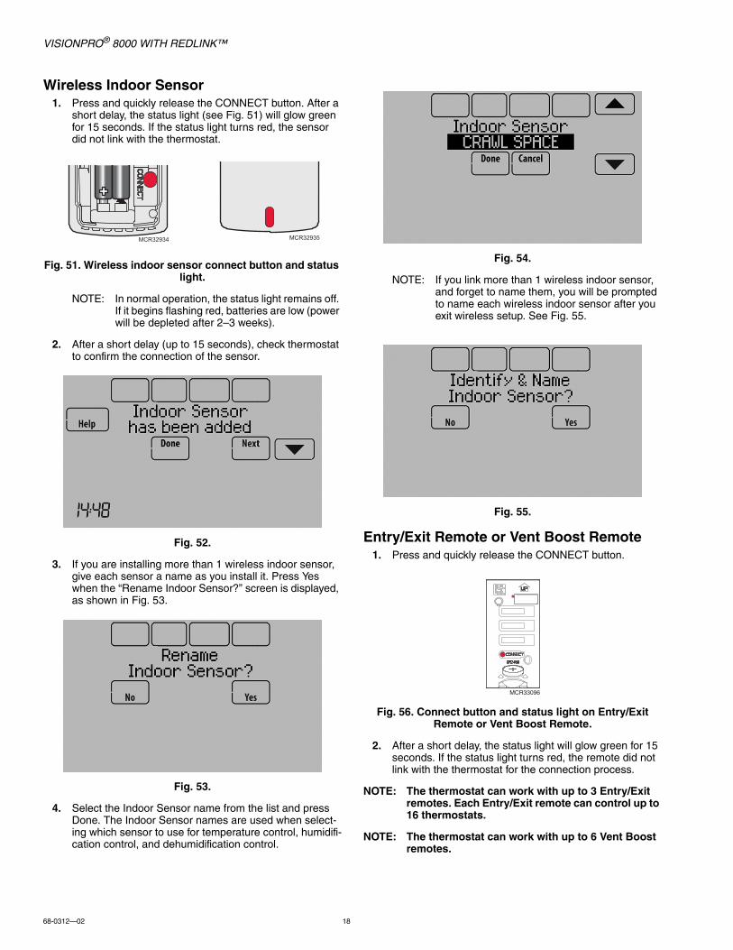
Wireless Indoor Sensor1. Press and quickly release the CONNECT button. After a
short delay, the status light (see Fig. 51) will glow green for 15 seconds. If the status light turns red, the sensor did not link with the thermostat.
Fig. 51. Wireless indoor sensor connect button and status light.
NOTE: In normal operation, the status light remains off. If it begins flashing red, batteries are low (power will be depleted after 2–3 weeks).
2. After a short delay (up to 15 seconds), check thermostat to confirm the connection of the sensor.
Fig. 52.
3. If you are installing more than 1 wireless indoor sensor, give each sensor a name as you install it. Press Yes when the “Rename Indoor Sensor?” screen is displayed, as shown in Fig. 53.
Fig. 53.
4. Select the Indoor Sensor name from the list and press Done. The Indoor Sensor names are used when select-ing which sensor to use for temperature control, humidifi-cation control, and dehumidification control.
Fig. 54.
NOTE: If you link more than 1 wireless indoor sensor, and forget to name them, you will be prompted to name each wireless indoor sensor after you exit wireless setup. See Fig. 55.
Fig. 55.
Entry/Exit Remote or Vent Boost Remote1. Press and quickly release the CONNECT button.
Fig. 56. Connect button and status light on Entry/Exit Remote or Vent Boost Remote.
2. After a short delay, the status light will glow green for 15 seconds. If the status light turns red, the remote did not link with the thermostat for the connection process.
NOTE: The thermostat can work with up to 3 Entry/Exit remotes. Each Entry/Exit remote can control up to 16 thermostats.
NOTE: The thermostat can work with up to 6 Vent Boost remotes.
MCR32934 MCR32935
MCR33096
VISIONPRO® 8000 WITH REDLINK™
19 68-0312—02
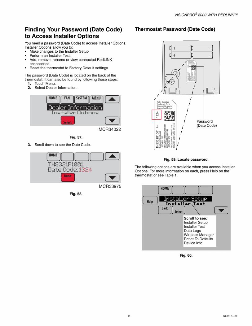
Finding Your Password (Date Code) to Access Installer OptionsYou need a password (Date Code) to access Installer Options. Installer Options allow you to:• Make changes to the Installer Setup.• Perform an Installer Test.• Add, remove, rename or view connected RedLINK
accessories.• Reset the thermostat to Factory Default settings.
The password (Date Code) is located on the back of the thermostat. It can also be found by following these steps:
1. Touch Menu.2. Select Dealer Information.
Fig. 57.
3. Scroll down to see the Date Code.
Fig. 58.
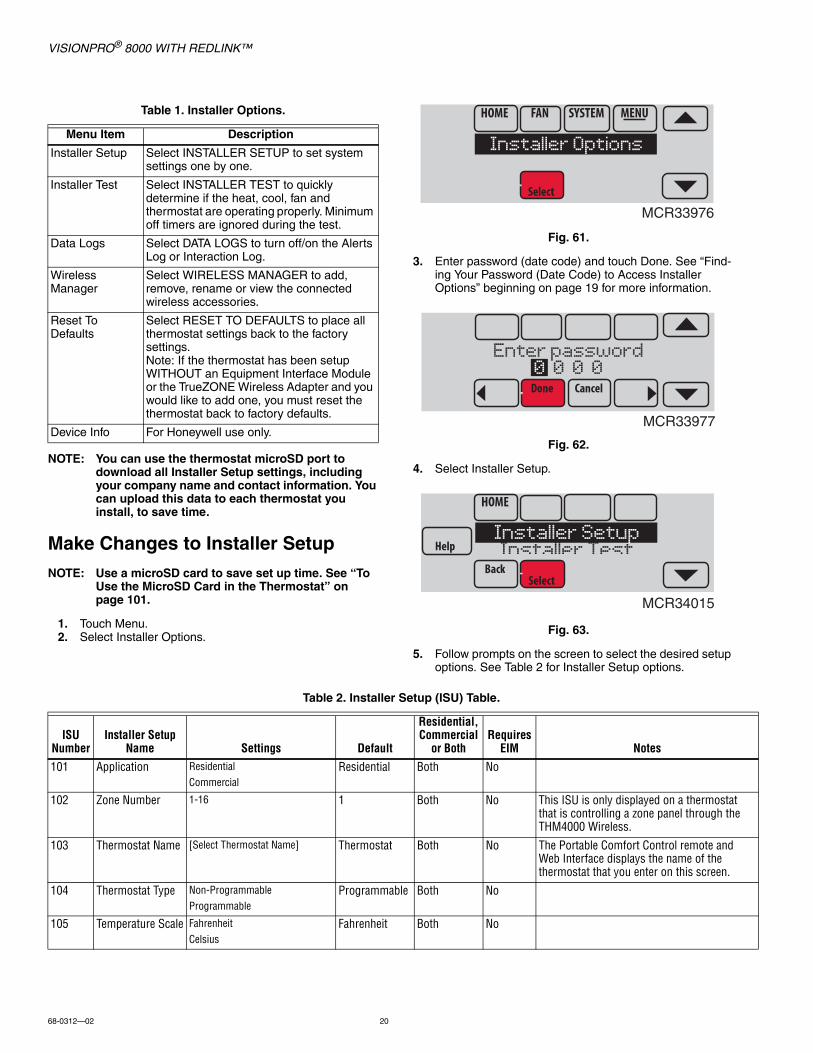
Thermostat Password (Date Code)
Fig. 59. Locate password.
The following options are available when you access Installer Options. For more information on each, press Help on the thermostat or see Table 1.
Fig. 60.
MCR34022
Dealer InformationInstaller Options
MCR33975
TH8321R1001Date Code: 1324
Resid
entia
l/Rés
iden
tiel
1-80
0-46
8-15
02
http
://yo
urho
me.h
oney
wel
l.com
Com
mer
cial/C
omm
ercia
le1-
888-
245-
1051
http
://cu
stom
er.h
oney
wel
l.com
Hone
ywell
, Gol
den V
alley
, MN
5542
2
RoHs CompliantConformité RoHsAssembled in MexicoAssemblé au Mexique
TH83
21R1
001
1
1324
Resid
entia
l/Rés
ident
iel1-
800-
468-
1502
ht
tp://
your
hom
e.hon
eywe
ll.com
Com
mer
cial/C
omm
ercia
le1-
888-
245-
1051
http
://cu
stom
er.ho
neyw
ell.co
mHo
neyw
ell, G
olden
Valle
y, MN
5542
2
RoHs CompliantConformité RoHsAssembled in MexicoAssemblé au Mexique
TH83
21R1
001
1
1324
Password (Date Code)
Scroll to see:Installer SetupInstaller TestData LogsWireless ManagerReset To DefaultsDevice Info
VISIONPRO® 8000 WITH REDLINK™
68-0312—02 20
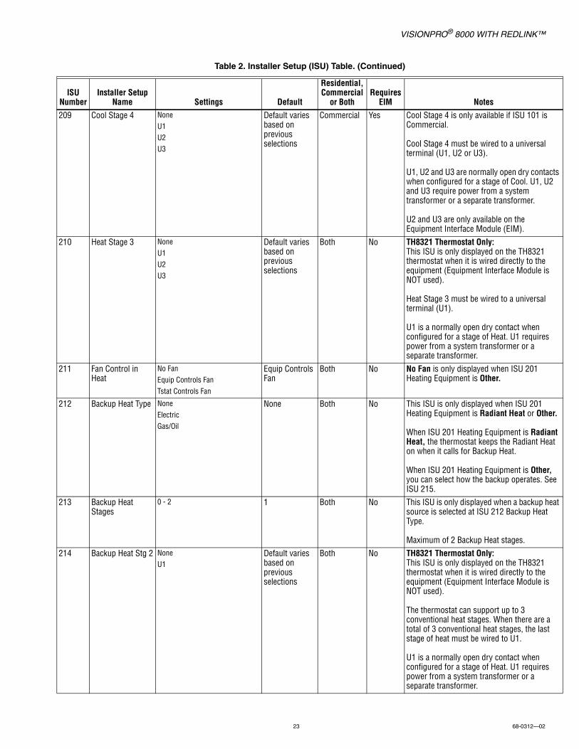
NOTE: You can use the thermostat microSD port to download all Installer Setup settings, including your company name and contact information. You can upload this data to each thermostat you install, to save time.
Make Changes to Installer SetupNOTE: Use a microSD card to save set up time. See “To
Use the MicroSD Card in the Thermostat” on page 101.
1. Touch Menu.2. Select Installer Options.
Fig. 61.
3. Enter password (date code) and touch Done. See “Find-ing Your Password (Date Code) to Access Installer Options” beginning on page 19 for more information.
Fig. 62.
4. Select Installer Setup.
Fig. 63.
5. Follow prompts on the screen to select the desired setup options. See Table 2 for Installer Setup options.
Table 1. Installer Options.
Menu Item Description
Installer Setup Select INSTALLER SETUP to set system settings one by one.
Installer Test Select INSTALLER TEST to quickly determine if the heat, cool, fan and thermostat are operating properly. Minimum off timers are ignored during the test.
Data Logs Select DATA LOGS to turn off/on the Alerts Log or Interaction Log.
Wireless Manager
Select WIRELESS MANAGER to add, remove, rename or view the connected wireless accessories.
Reset To Defaults
Select RESET TO DEFAULTS to place all thermostat settings back to the factory settings.Note: If the thermostat has been setup WITHOUT an Equipment Interface Module or the TrueZONE Wireless Adapter and you would like to add one, you must reset the thermostat back to factory defaults.
Device Info For Honeywell use only.
MCR33976
Installer Options
MCR33977
Enter password0 0 0 0
MCR34015
Installer SetupInstaller Test
Table 2. Installer Setup (ISU) Table.
ISU Number
Installer Setup Name Settings Default
Residential, Commercial
or BothRequires
EIM Notes
101 Application ResidentialCommercial
Residential Both No
102 Zone Number 1-16 1 Both No This ISU is only displayed on a thermostat that is controlling a zone panel through the THM4000 Wireless.
103 Thermostat Name [Select Thermostat Name] Thermostat Both No The Portable Comfort Control remote and Web Interface displays the name of the thermostat that you enter on this screen.
104 Thermostat Type Non-ProgrammableProgrammable
Programmable Both No
105 Temperature Scale FahrenheitCelsius
Fahrenheit Both No

VISIONPRO® 8000 WITH REDLINK™
21 68-0312—02
106 Outdoor Air Sensor
NoYes
No Both No This ISU automatically defaults to Yes when a Wireless Outdoor Sensor is connected.
An Outdoor Sensor is required to set the following ISUs:ISU 312 Outdoor Temperature Lockouts (Heat Pump Lockout and Backup Heat Lockout)ISU 405 Outdoor Temperature used with Minimum Heat Recovery Ramp RateISU 406 Outdoor Temperature used with Maximum Heat Recovery Ramp RateISU 407 Outdoor Temperature used with Minimum Cool Recovery Ramp RateISU 408 Outdoor Temperature used with Maximum Cool Recovery Ramp RateISU 805 Humidification - Window ProtectionISU 1013 Low Outdoor Temperature Ventilation LockoutISU 1013 High Outdoor Temperature Ventilation LockoutISU 1013 High Outdoor Dew Point Ventilation Lockout (requires Wireless Outdoor Sensor)
200 Heating System Conv. Forced AirHeat PumpRadiant HeatOtherNone (Cool Only)
Conv. Forced Air
Both No
201 Heating Equipment
Heat Pump:Air to Air Heat PumpGeothermalGeothermal Radiant
Air to Air Heat Pump
Both No This ISU is not displayed when ISU 200 Heating System is set to Conv. Forced Air, Radiant Heat, Other or None (Cool Only).
See “Geothermal Radiant Heat” beginning on page 78.
203 Radiant Stage 1 NoneU1U2U3
Default varies based on previous selections
Both No This ISU is only displayed when ISU 201 Heating Equipment is Geothermal Radiant.
Geothermal Radiant Heat must be wired to a universal terminal (U1, U2, or U3).
U1, U2 and U3 are normally open dry contacts when configured for a stage of Heat. U1, U2 and U3 require power from the system transformer or a separate transformer.
U2 and U3 are only available on the Equipment Interface Module (EIM).
204 Radiant Stage 2 NoneU1U2U3
Default varies based on previous selections
Both No This ISU is only displayed when ISU 201 Heating Equipment is Geothermal Radiant.
Geothermal Radiant Heat must be wired to a universal terminal (U1, U2, or U3).
U1, U2 and U3 are normally open dry contacts when configured for a stage of Heat. U1, U2 and U3 require power from the system transformer or a separate transformer.
U2 and U3 are only available on the Equipment Interface Module (EIM).
Table 2. Installer Setup (ISU) Table. (Continued)
ISU Number
Installer Setup Name Settings Default
Residential, Commercial
or BothRequires
EIM Notes

VISIONPRO® 8000 WITH REDLINK™
68-0312—02 22
205 Geo Forced Air NoneCooling OnlyHeating and Cooling
Heating and Cooling
Both No This thermostat has the capability of controlling Geothermal Radiant Heat, Geothermal Forced Air and Backup Heat.
If this thermostat is not controlling the Geothermal Forced Air System, select None. This setting is typically used if the thermostat is only controlling Geothermal Radiant Heat.
If this thermostat is using the Geothermal Forced Air System for cooling and not for heating, select Cooling Only.
If this thermostat is using the Geothermal Forced Air System for both heating and cooling, select Heating and Cooling.
206 Reversing Valve O (O/B on Cool)B (O/B on Heat)
O/B on Cool Both No Only displayed if the equipment type is Air to Air Heat Pump, Geothermal or Geothermal Radiant.
207 Cool Stages / Compressor Stages
1-4 1 if ISU 101 is Residential
2 if ISU 101 is Commercial
Both No Conventional:Cool Stage 3 and 4 are only available if ISU 101 is Commercial.
Cool Stage 3 and 4 must be wired to a universal terminal (U1, U2 or U3).
Heat Pumps:Maximum of 2 Compressor Stages for heat pump systems.
202, 207
Heat Stages / Backup Heat Stages
1 - 3 Default is 1 stage if ISU 101 Application is Residential
Default is 2 stages if ISU 101 Application is Commercial
Both No Maximum of 3 Heat Stages for conventional systems.
Maximum of 2 Backup Heat Stages for systems with more than 1 heating equipment type.
208 Cool Stage 3 NoneU1U2U3
Default varies based on previous selections
Commercial No Cool Stage 3 is only available if ISU 1010 is Commercial.
Cool Stage 3 must be wired to a universal terminal (U1, U2 or U3).
U1, U2 and U3 are normally open dry contacts when configured for a stage of Cool. U1, U2 and U3 require power from a system transformer or a separate transformer.
U2 and U3 are only available on the Equipment Interface Module (EIM).
Table 2. Installer Setup (ISU) Table. (Continued)
ISU Number
Installer Setup Name Settings Default
Residential, Commercial
or BothRequires
EIM Notes
VISIONPRO® 8000 WITH REDLINK™
23 68-0312—02
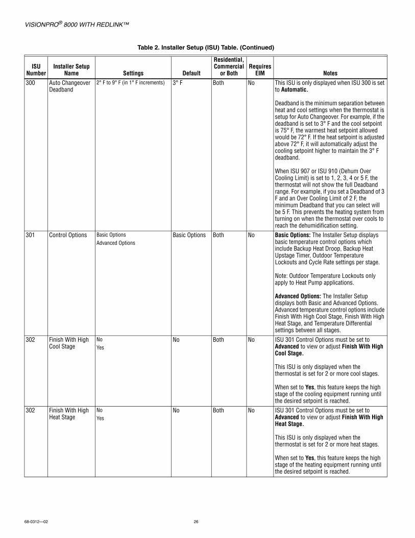
209 Cool Stage 4 NoneU1U2U3
Default varies based on previous selections
Commercial Yes Cool Stage 4 is only available if ISU 101 is Commercial.
Cool Stage 4 must be wired to a universal terminal (U1, U2 or U3).
U1, U2 and U3 are normally open dry contacts when configured for a stage of Cool. U1, U2 and U3 require power from a system transformer or a separate transformer.
U2 and U3 are only available on the Equipment Interface Module (EIM).
210 Heat Stage 3 NoneU1U2U3
Default varies based on previous selections
Both No TH8321 Thermostat Only:This ISU is only displayed on the TH8321 thermostat when it is wired directly to the equipment (Equipment Interface Module is NOT used).
Heat Stage 3 must be wired to a universal terminal (U1).
U1 is a normally open dry contact when configured for a stage of Heat. U1 requires power from a system transformer or a separate transformer.
211 Fan Control in Heat
No FanEquip Controls FanTstat Controls Fan
Equip Controls Fan
Both No No Fan is only displayed when ISU 201 Heating Equipment is Other.
212 Backup Heat Type NoneElectricGas/Oil
None Both No This ISU is only displayed when ISU 201 Heating Equipment is Radiant Heat or Other.
When ISU 201 Heating Equipment is Radiant Heat, the thermostat keeps the Radiant Heat on when it calls for Backup Heat.
When ISU 201 Heating Equipment is Other, you can select how the backup operates. See ISU 215.
213 Backup Heat Stages
0 - 2 1 Both No This ISU is only displayed when a backup heat source is selected at ISU 212 Backup Heat Type.
Maximum of 2 Backup Heat stages.
214 Backup Heat Stg 2 NoneU1
Default varies based on previous selections
Both No TH8321 Thermostat Only:This ISU is only displayed on the TH8321 thermostat when it is wired directly to the equipment (Equipment Interface Module is NOT used).
The thermostat can support up to 3 conventional heat stages. When there are a total of 3 conventional heat stages, the last stage of heat must be wired to U1.
U1 is a normally open dry contact when configured for a stage of Heat. U1 requires power from a system transformer or a separate transformer.
Table 2. Installer Setup (ISU) Table. (Continued)
ISU Number
Installer Setup Name Settings Default
Residential, Commercial
or BothRequires
EIM Notes

VISIONPRO® 8000 WITH REDLINK™
68-0312—02 24
215 Run Backup Heat with Primary
NoYes
No Both No This ISU is only displayed when ISU 201 Heating Equipment is Other.
When ISU 201 Heating Equipment is Other, you can select how the Backup Heat operates. The thermostat can be setup to keep the primary heat source on when it calls for Backup Heat or the thermostat can be setup to turn off the primary heat source when it calls for Backup Heat.
When ISU 201 Heating Equipment is Radiant Heat, the thermostat keeps the Radiant Heat on when it calls for Backup Heat.
216 Backup Heat Fan Equip Controls FanTstat Controls Fan
Tstat Controls Fan
Both No This ISU is only displayed for conventional systems when ISU 212 Backup Heat Type is Electric.
Backup Heat Fan Operation automatically defaults to Equip Controls Fan when ISU 212 Backup Heat Type is Gas/Oil.
217 Backup Heat Stage 2
NoneU1
Default varies based on previous selections
Both No TH8321 Thermostat Only:This ISU is only displayed on the TH8321 thermostat when it is wired directly to the equipment (Equipment Interface Module is NOT used).
The thermostat can support up to 2 backup heat stages for heat pump applications. When there are 2 backup heat stages, backup heat stage 2 must be wired to U1.
U1 is a normally open dry contact when configured for a stage of Heat. U1 requires power from a system transformer or a separate transformer.
218 Backup Heat Type Electric Gas/Oil
Electric Both No This ISU is only displayed when ISU 201 Heating Equipment is Air to Air Heat Pump, Geothermal or Geothermal Radiant and there is at least one stage of backup heat.
See “Heat Pump and Backup Heat Operation” beginning on page 78.
219 External Fossil Fuel Kit
NoYes
No Both No This ISU is only displayed when ISU 201 Heating Equipment is Air to Air Heat Pump, Geothermal or Geothermal Radiant and ISU 218 Backup Heat Type is Gas/Oil.
Table 2. Installer Setup (ISU) Table. (Continued)
ISU Number
Installer Setup Name Settings Default
Residential, Commercial
or BothRequires
EIM Notes

VISIONPRO® 8000 WITH REDLINK™
25 68-0312—02
222 A-L/A Terminal NoneTime Of DayEconomizerHeat Pump Fault
None Commercial No This ISU is only displayed when ISU 101 Application is Commercial.
Note: When the thermostat is setup for Residential, the L/A terminal operates as described under "Heat Pump Fault". The L/A terminal requires no setup for residential applications.
None: The A-L/A terminal is not used.
Time of Day: The A-L/A terminal is energized during Occupied periods and when the user overrides the temperature. The terminal is de-energized during Unoccupied periods and in Standby mode.
Economizer: The thermostat controls an economizer module to provide ventilation during Occupied periods and free cooling when outdoor conditions are favorable. The A-L/A terminal is energized during Occupied periods and during a call for cooling in Unoccupied periods. See “Economizer and Time of Day (TOD) Operation” beginning on page 106.Notes: The economizer module determines when outdoor conditions are favorable for free cooling.
Heat Pump Fault: When 24 volts is detected on the L/A terminal (compressor monitor), the thermostat displays a message to alert the user when the heat pump requires service. The L/A terminal sends a continuous output to a zone panel when the thermostat is set to Emergency Heat mode. The zone panel will not turn on the heat pump when a zone is set to Emergency Heat mode.
300 System Changeover
Manual Automatic
Manual:if ISU 101 is Residential
Automatic:if ISU 101 is Commercial
Both No Manual: The user must select heating or cooling as needed to maintain the desired indoor temperature.
Automatic: The user has the option to select Auto for the system setting. In Auto mode, the thermostat controls heating and cooling equipment as needed to maintain the desired indoor temperature.
Table 2. Installer Setup (ISU) Table. (Continued)
ISU Number
Installer Setup Name Settings Default
Residential, Commercial
or BothRequires
EIM Notes
VISIONPRO® 8000 WITH REDLINK™
68-0312—02 26
300 Auto Changeover Deadband
2° F to 9° F (in 1° F increments) 3° F Both No This ISU is only displayed when ISU 300 is set to Automatic.
Deadband is the minimum separation between heat and cool settings when the thermostat is setup for Auto Changeover. For example, if the deadband is set to 3° F and the cool setpoint is 75° F, the warmest heat setpoint allowed would be 72° F. If the heat setpoint is adjusted above 72° F, it will automatically adjust the cooling setpoint higher to maintain the 3° F deadband.
When ISU 907 or ISU 910 (Dehum Over Cooling Limit) is set to 1, 2, 3, 4 or 5 F, the thermostat will not show the full Deadband range. For example, if you set a Deadband of 3 F and an Over Cooling Limit of 2 F, the minimum Deadband that you can select will be 5 F. This prevents the heating system from turning on when the thermostat over cools to reach the dehumidification setting.
301 Control Options Basic OptionsAdvanced Options
Basic Options Both No Basic Options: The Installer Setup displays basic temperature control options which include Backup Heat Droop, Backup Heat Upstage Timer, Outdoor Temperature Lockouts and Cycle Rate settings per stage.
Note: Outdoor Temperature Lockouts only apply to Heat Pump applications.
Advanced Options: The Installer Setup displays both Basic and Advanced Options. Advanced temperature control options include Finish With High Cool Stage, Finish With High Heat Stage, and Temperature Differential settings between all stages.
302 Finish With High Cool Stage
No Yes
No Both No ISU 301 Control Options must be set to Advanced to view or adjust Finish With High Cool Stage.
This ISU is only displayed when the thermostat is set for 2 or more cool stages.
When set to Yes, this feature keeps the high stage of the cooling equipment running until the desired setpoint is reached.
302 Finish With High Heat Stage
No Yes
No Both No ISU 301 Control Options must be set to Advanced to view or adjust Finish With High Heat Stage.
This ISU is only displayed when the thermostat is set for 2 or more heat stages.
When set to Yes, this feature keeps the high stage of the heating equipment running until the desired setpoint is reached.
Table 2. Installer Setup (ISU) Table. (Continued)
ISU Number
Installer Setup Name Settings Default
Residential, Commercial
or BothRequires
EIM Notes
VISIONPRO® 8000 WITH REDLINK™
27 68-0312—02
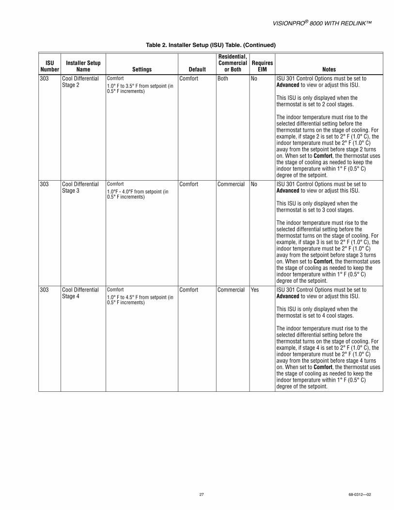
303 Cool Differential Stage 2
Comfort 1.0° F to 3.5° F from setpoint (in 0.5° F increments)
Comfort Both No ISU 301 Control Options must be set to Advanced to view or adjust this ISU.
This ISU is only displayed when the thermostat is set to 2 cool stages.
The indoor temperature must rise to the selected differential setting before the thermostat turns on the stage of cooling. For example, if stage 2 is set to 2° F (1.0° C), the indoor temperature must be 2° F (1.0° C) away from the setpoint before stage 2 turns on. When set to Comfort, the thermostat uses the stage of cooling as needed to keep the indoor temperature within 1° F (0.5° C) degree of the setpoint.
303 Cool Differential Stage 3
Comfort 1.0°F - 4.0°F from setpoint (in 0.5° F increments)
Comfort Commercial No ISU 301 Control Options must be set to Advanced to view or adjust this ISU.
This ISU is only displayed when the thermostat is set to 3 cool stages.
The indoor temperature must rise to the selected differential setting before the thermostat turns on the stage of cooling. For example, if stage 3 is set to 2° F (1.0° C), the indoor temperature must be 2° F (1.0° C) away from the setpoint before stage 3 turns on. When set to Comfort, the thermostat uses the stage of cooling as needed to keep the indoor temperature within 1° F (0.5° C) degree of the setpoint.
303 Cool Differential Stage 4
Comfort 1.0° F to 4.5° F from setpoint (in 0.5° F increments)
Comfort Commercial Yes ISU 301 Control Options must be set to Advanced to view or adjust this ISU.
This ISU is only displayed when the thermostat is set to 4 cool stages.
The indoor temperature must rise to the selected differential setting before the thermostat turns on the stage of cooling. For example, if stage 4 is set to 2° F (1.0° C), the indoor temperature must be 2° F (1.0° C) away from the setpoint before stage 4 turns on. When set to Comfort, the thermostat uses the stage of cooling as needed to keep the indoor temperature within 1° F (0.5° C) degree of the setpoint.
Table 2. Installer Setup (ISU) Table. (Continued)
ISU Number
Installer Setup Name Settings Default
Residential, Commercial
or BothRequires
EIM Notes

VISIONPRO® 8000 WITH REDLINK™
68-0312—02 28
304 Radiant Heat Diff. Stage 2
Comfort 1.0° F to 3.5° F from setpoint (in 0.5° F increments)
Comfort Both No ISU 301 Control Options must be set to Advanced to view or adjust this ISU.
This ISU is only displayed if ISU 201 Heating Equipment is Geothermal Radiant and there are 2 radiant heat stages.
The indoor temperature must drop to the selected differential setting before the thermostat will turn on the stage of heating. For example, if stage 2 is set to 2° F (1.0° C), the indoor temperature must be 2° F (1.0° C) away from the setpoint before stage 2 turns on. When set to Comfort, the thermostat will use the stage of heating as needed to keep the indoor temperature within 1° F (0.5° C) degree of the setpoint.
305 Heat Differential Stage 2
Note: Depending on the application, the text displayed on the screen may show the specific heating equipment type
Comfort 1.0° F to 3.5° F from setpoint (in 0.5° F increments)
Comfort Both No ISU 301 Control Options must be set to Advanced to view or adjust this ISU.
This ISU is only displayed for conventional systems that have 2 heat stages.
The indoor temperature must drop to the selected differential setting before the thermostat will turn on the stage of heating. For example, if stage 2 is set to 2° F (1.0° C), the indoor temperature must be 2° F (1.0° C) away from the setpoint before stage 2 turns on. When set to Comfort, the thermostat will use the stage of heating as needed to keep the indoor temperature within 1° F (0.5° C) degree of the setpoint.
305 Heat Differential Stage 3
Note: Depending on the application, the text displayed on the screen may show the specific heating equipment type
Comfort 1.0° F to 4.0° F from setpoint (in 0.5° F increments)
Comfort Both No ISU 301Temperature Control Options must be set to Advanced to view or adjust this ISU.
This ISU is only displayed for conventional systems that have 3 heat stages.
The indoor temperature must drop to the selected differential setting before the thermostat will turn on the stage of heating. For example, if stage 3 is set to 2° F (1.0° C), the indoor temperature must be 2° F (1.0° C) away from the setpoint before stage 3 turns on. When set to Comfort, the thermostat will use the stage of heating as needed to keep the indoor temperature within 1° F (0.5° C) degree of the setpoint.
Table 2. Installer Setup (ISU) Table. (Continued)
ISU Number
Installer Setup Name Settings Default
Residential, Commercial
or BothRequires
EIM Notes
VISIONPRO® 8000 WITH REDLINK™
29 68-0312—02
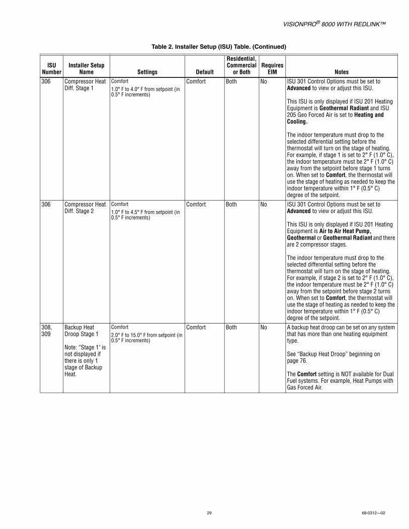
306 Compressor Heat Diff. Stage 1
Comfort1.0° F to 4.0° F from setpoint (in 0.5° F increments)
Comfort Both No ISU 301 Control Options must be set to Advanced to view or adjust this ISU.
This ISU is only displayed if ISU 201 Heating Equipment is Geothermal Radiant and ISU 205 Geo Forced Air is set to Heating and Cooling.
The indoor temperature must drop to the selected differential setting before the thermostat will turn on the stage of heating. For example, if stage 1 is set to 2° F (1.0° C), the indoor temperature must be 2° F (1.0° C) away from the setpoint before stage 1 turns on. When set to Comfort, the thermostat will use the stage of heating as needed to keep the indoor temperature within 1° F (0.5° C) degree of the setpoint.
306 Compressor Heat Diff. Stage 2
Comfort1.0° F to 4.5° F from setpoint (in 0.5° F increments)
Comfort Both No ISU 301 Control Options must be set to Advanced to view or adjust this ISU.
This ISU is only displayed if ISU 201 Heating Equipment is Air to Air Heat Pump, Geothermal or Geothermal Radiant and there are 2 compressor stages.
The indoor temperature must drop to the selected differential setting before the thermostat will turn on the stage of heating. For example, if stage 2 is set to 2° F (1.0° C), the indoor temperature must be 2° F (1.0° C) away from the setpoint before stage 2 turns on. When set to Comfort, the thermostat will use the stage of heating as needed to keep the indoor temperature within 1° F (0.5° C) degree of the setpoint.
308, 309
Backup Heat Droop Stage 1
Note: “Stage 1" is not displayed if there is only 1 stage of Backup Heat.
Comfort2.0° F to 15.0° F from setpoint (in 0.5° F increments)
Comfort Both No A backup heat droop can be set on any system that has more than one heating equipment type.
See “Backup Heat Droop” beginning on page 76.
The Comfort setting is NOT available for Dual Fuel systems. For example, Heat Pumps with Gas Forced Air.
Table 2. Installer Setup (ISU) Table. (Continued)
ISU Number
Installer Setup Name Settings Default
Residential, Commercial
or BothRequires
EIM Notes
VISIONPRO® 8000 WITH REDLINK™
68-0312—02 30
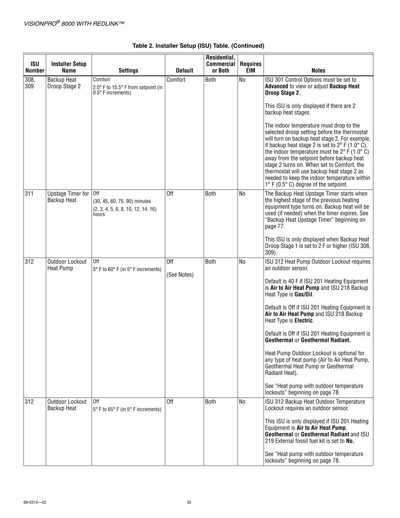
308, 309
Backup Heat Droop Stage 2
Comfort2.0° F to 15.5° F from setpoint (in 0.5° F increments)
Comfort Both No ISU 301 Control Options must be set to Advanced to view or adjust Backup Heat Droop Stage 2.
This ISU is only displayed if there are 2 backup heat stages.
The indoor temperature must drop to the selected droop setting before the thermostat will turn on backup heat stage 2. For example, if backup heat stage 2 is set to 2° F (1.0° C), the indoor temperature must be 2° F (1.0° C) away from the setpoint before backup heat stage 2 turns on. When set to Comfort, the thermostat will use backup heat stage 2 as needed to keep the indoor temperature within 1° F (0.5° C) degree of the setpoint.
311 Upstage Timer for Backup Heat
Off (30, 45, 60, 75, 90) minutes (2, 3, 4, 5, 6, 8, 10, 12, 14, 16) hours
Off Both No The Backup Heat Upstage Timer starts when the highest stage of the previous heating equipment type turns on. Backup heat will be used (if needed) when the timer expires. See “Backup Heat Upstage Timer” beginning on page 77.
This ISU is only displayed when Backup Heat Droop Stage 1 is set to 2 F or higher (ISU 308, 309).
312 Outdoor Lockout Heat Pump
Off 5° F to 60° F (in 5° F increments)
Off
(See Notes)
Both No ISU 312 Heat Pump Outdoor Lockout requires an outdoor sensor.
Default is 40 F if ISU 201 Heating Equipment is Air to Air Heat Pump and ISU 218 Backup Heat Type is Gas/Oil.
Default is Off if ISU 201 Heating Equipment is Air to Air Heat Pump and ISU 218 Backup Heat Type is Electric.
Default is Off if ISU 201 Heating Equipment is Geothermal or Geothermal Radiant.
Heat Pump Outdoor Lockout is optional for any type of heat pump (Air to Air Heat Pump, Geothermal Heat Pump or Geothermal Radiant Heat).
See “Heat pump with outdoor temperature lockouts” beginning on page 78.
312 Outdoor Lockout Backup Heat
Off 5° F to 65° F (in 5° F increments)
Off Both No ISU 312 Backup Heat Outdoor Temperature Lockout requires an outdoor sensor.
This ISU is only displayed if ISU 201 Heating Equipment is Air to Air Heat Pump, Geothermal or Geothermal Radiant and ISU 219 External fossil fuel kit is set to No.
See “Heat pump with outdoor temperature lockouts” beginning on page 78.
Table 2. Installer Setup (ISU) Table. (Continued)
ISU Number
Installer Setup Name Settings Default
Residential, Commercial
or BothRequires
EIM Notes
VISIONPRO® 8000 WITH REDLINK™
31 68-0312—02
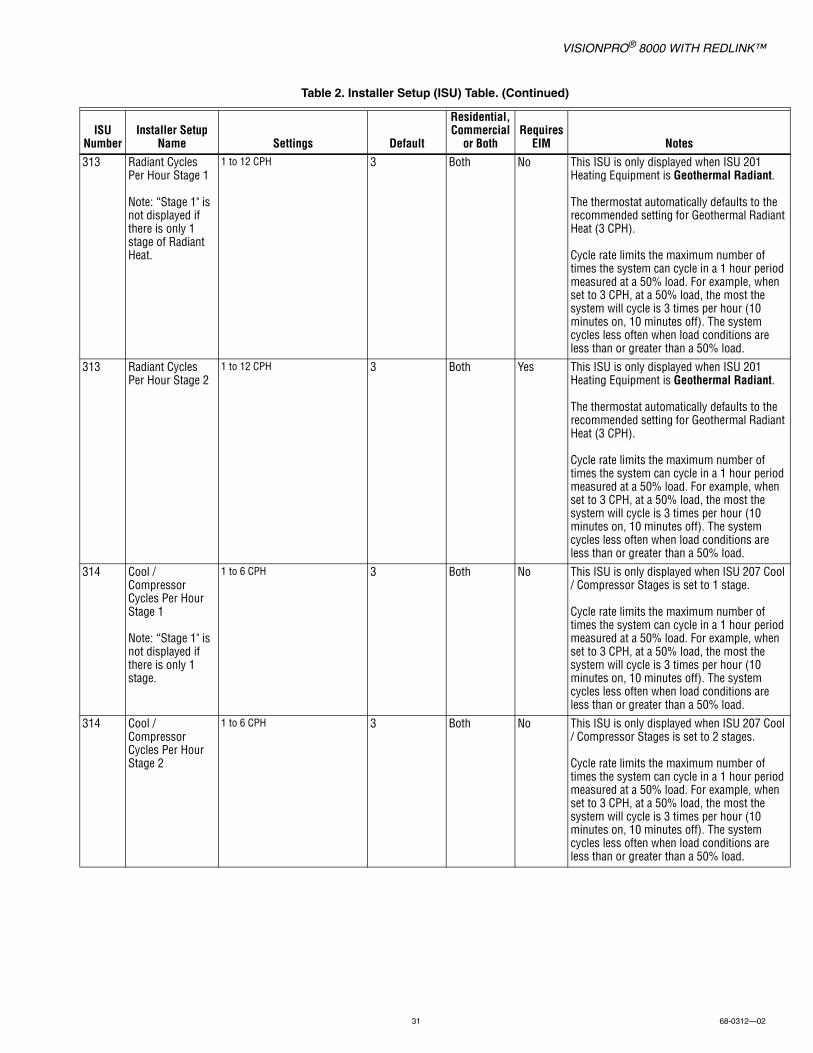
313 Radiant Cycles Per Hour Stage 1
Note: “Stage 1" is not displayed if there is only 1 stage of Radiant Heat.
1 to 12 CPH 3 Both No This ISU is only displayed when ISU 201 Heating Equipment is Geothermal Radiant.
The thermostat automatically defaults to the recommended setting for Geothermal Radiant Heat (3 CPH).
Cycle rate limits the maximum number of times the system can cycle in a 1 hour period measured at a 50% load. For example, when set to 3 CPH, at a 50% load, the most the system will cycle is 3 times per hour (10 minutes on, 10 minutes off). The system cycles less often when load conditions are less than or greater than a 50% load.
313 Radiant Cycles Per Hour Stage 2
1 to 12 CPH 3 Both Yes This ISU is only displayed when ISU 201 Heating Equipment is Geothermal Radiant.
The thermostat automatically defaults to the recommended setting for Geothermal Radiant Heat (3 CPH).
Cycle rate limits the maximum number of times the system can cycle in a 1 hour period measured at a 50% load. For example, when set to 3 CPH, at a 50% load, the most the system will cycle is 3 times per hour (10 minutes on, 10 minutes off). The system cycles less often when load conditions are less than or greater than a 50% load.
314 Cool / Compressor Cycles Per Hour Stage 1
Note: “Stage 1" is not displayed if there is only 1 stage.
1 to 6 CPH 3 Both No This ISU is only displayed when ISU 207 Cool / Compressor Stages is set to 1 stage.
Cycle rate limits the maximum number of times the system can cycle in a 1 hour period measured at a 50% load. For example, when set to 3 CPH, at a 50% load, the most the system will cycle is 3 times per hour (10 minutes on, 10 minutes off). The system cycles less often when load conditions are less than or greater than a 50% load.
314 Cool / Compressor Cycles Per Hour Stage 2
1 to 6 CPH 3 Both No This ISU is only displayed when ISU 207 Cool / Compressor Stages is set to 2 stages.
Cycle rate limits the maximum number of times the system can cycle in a 1 hour period measured at a 50% load. For example, when set to 3 CPH, at a 50% load, the most the system will cycle is 3 times per hour (10 minutes on, 10 minutes off). The system cycles less often when load conditions are less than or greater than a 50% load.
Table 2. Installer Setup (ISU) Table. (Continued)
ISU Number
Installer Setup Name Settings Default
Residential, Commercial
or BothRequires
EIM Notes
VISIONPRO® 8000 WITH REDLINK™
68-0312—02 32
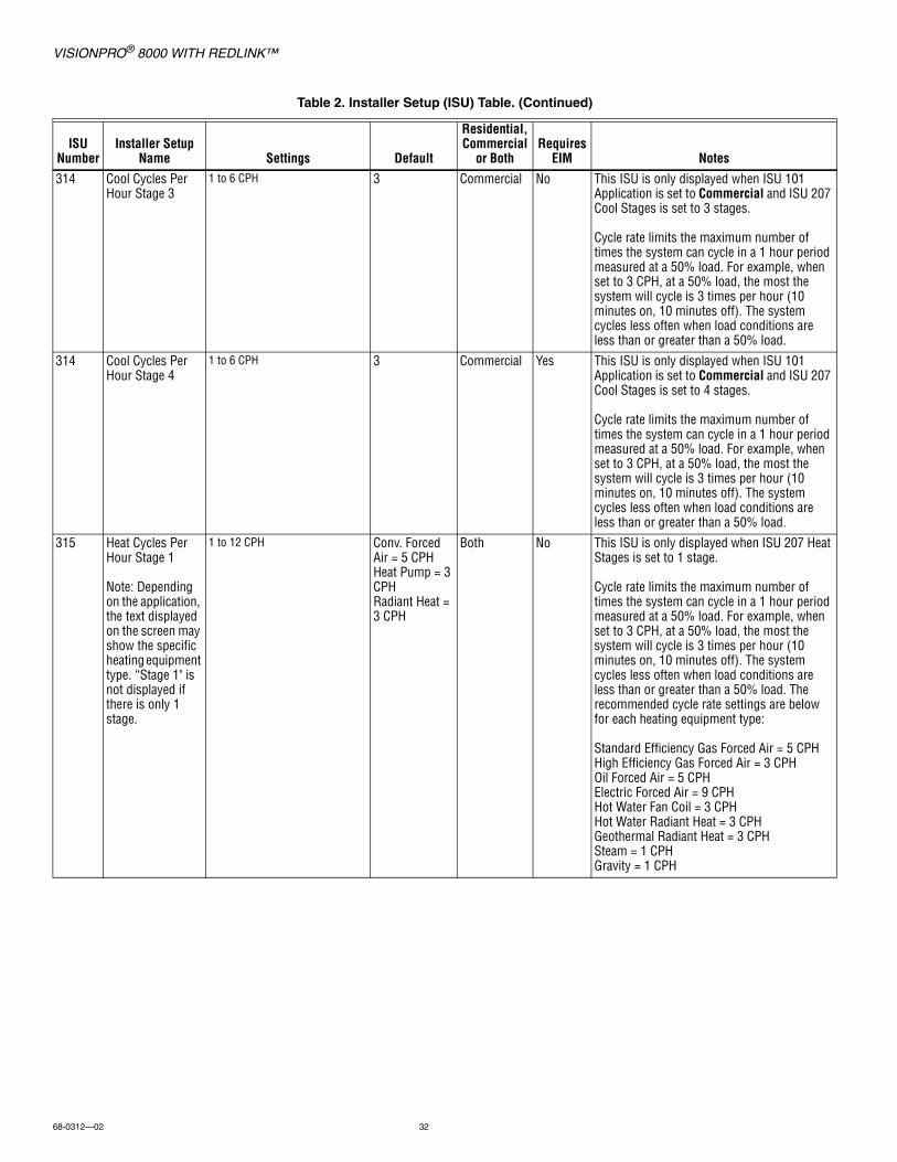
314 Cool Cycles Per Hour Stage 3
1 to 6 CPH 3 Commercial No This ISU is only displayed when ISU 101 Application is set to Commercial and ISU 207 Cool Stages is set to 3 stages.
Cycle rate limits the maximum number of times the system can cycle in a 1 hour period measured at a 50% load. For example, when set to 3 CPH, at a 50% load, the most the system will cycle is 3 times per hour (10 minutes on, 10 minutes off). The system cycles less often when load conditions are less than or greater than a 50% load.
314 Cool Cycles Per Hour Stage 4
1 to 6 CPH 3 Commercial Yes This ISU is only displayed when ISU 101 Application is set to Commercial and ISU 207 Cool Stages is set to 4 stages.
Cycle rate limits the maximum number of times the system can cycle in a 1 hour period measured at a 50% load. For example, when set to 3 CPH, at a 50% load, the most the system will cycle is 3 times per hour (10 minutes on, 10 minutes off). The system cycles less often when load conditions are less than or greater than a 50% load.
315 Heat Cycles Per Hour Stage 1
Note: Depending on the application, the text displayed on the screen may show the specific heating equipment type. “Stage 1" is not displayed if there is only 1 stage.
1 to 12 CPH Conv. Forced Air = 5 CPHHeat Pump = 3 CPHRadiant Heat = 3 CPH
Both No This ISU is only displayed when ISU 207 Heat Stages is set to 1 stage.
Cycle rate limits the maximum number of times the system can cycle in a 1 hour period measured at a 50% load. For example, when set to 3 CPH, at a 50% load, the most the system will cycle is 3 times per hour (10 minutes on, 10 minutes off). The system cycles less often when load conditions are less than or greater than a 50% load. The recommended cycle rate settings are below for each heating equipment type:
Standard Efficiency Gas Forced Air = 5 CPHHigh Efficiency Gas Forced Air = 3 CPHOil Forced Air = 5 CPHElectric Forced Air = 9 CPHHot Water Fan Coil = 3 CPHHot Water Radiant Heat = 3 CPHGeothermal Radiant Heat = 3 CPHSteam = 1 CPHGravity = 1 CPH
Table 2. Installer Setup (ISU) Table. (Continued)
ISU Number
Installer Setup Name Settings Default
Residential, Commercial
or BothRequires
EIM Notes

VISIONPRO® 8000 WITH REDLINK™
33 68-0312—02
315 Heat Cycles Per Hour Stage 2
Note: Depending on the application, the text displayed on the screen may show the specific heating equipment type.
1 to 12 CPH Conv. Forced Air = 5 CPHHeat Pump = 3 CPHRadiant Heat = 3 CPH
Both No This ISU is only displayed when ISU 207 Heat Stages is set to 2 stages.Cycle rate limits the maximum number of times the system can cycle in a 1 hour period measured at a 50% load. For example, when set to 3 CPH, at a 50% load, the most the system will cycle is 3 times per hour (10 minutes on, 10 minutes off). The system cycles less often when load conditions are less than or greater than a 50% load. The recommended cycle rate settings are below for each heating equipment type:
Standard Efficiency Gas Forced Air = 5 CPHHigh Efficiency Gas Forced Air = 3 CPHOil Forced Air = 5 CPHElectric Forced Air = 9 CPHHot Water Fan Coil = 3 CPHHot Water Radiant Heat = 3 CPHGeothermal Radiant Heat = 3 CPHSteam = 1 CPHGravity = 1 CPH
315 Heat Cycles Per Hour Stage 3
Note: Depending on the application, the text displayed on the screen may show the specific heating equipment type.
1 to 12 CPH Conv. Forced Air = 5 CPHHeat Pump = 3 CPHRadiant Heat = 3 CPH
Both No This ISU is only displayed when ISU 207 Heat Stages is set to 3 stages.
Cycle rate limits the maximum number of times the system can cycle in a 1 hour period measured at a 50% load. For example, when set to 3 CPH, at a 50% load, the most the system will cycle is 3 times per hour (10 minutes on, 10 minutes off). The system cycles less often when load conditions are less than or greater than a 50% load. The recommended cycle rate settings are below for each heating equipment type:
Standard Efficiency Gas Forced Air = 5 CPHHigh Efficiency Gas Forced Air = 3 CPHOil Forced Air = 5 CPHElectric Forced Air = 9 CPHHot Water Fan Coil = 3 CPHHot Water Radiant Heat = 3 CPHGeothermal Radiant Heat = 3 CPHSteam = 1 CPHGravity = 1 CPH
Table 2. Installer Setup (ISU) Table. (Continued)
ISU Number
Installer Setup Name Settings Default
Residential, Commercial
or BothRequires
EIM Notes
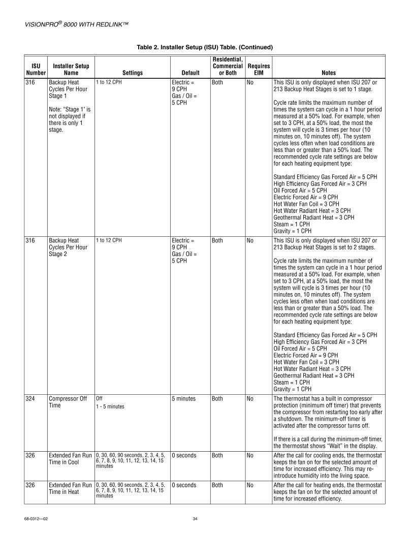
VISIONPRO® 8000 WITH REDLINK™
68-0312—02 34
316 Backup Heat Cycles Per Hour Stage 1
Note: “Stage 1" is not displayed if there is only 1 stage.
1 to 12 CPH Electric = 9 CPHGas / Oil = 5 CPH
Both No This ISU is only displayed when ISU 207 or 213 Backup Heat Stages is set to 1 stage.
Cycle rate limits the maximum number of times the system can cycle in a 1 hour period measured at a 50% load. For example, when set to 3 CPH, at a 50% load, the most the system will cycle is 3 times per hour (10 minutes on, 10 minutes off). The system cycles less often when load conditions are less than or greater than a 50% load. The recommended cycle rate settings are below for each heating equipment type:
Standard Efficiency Gas Forced Air = 5 CPHHigh Efficiency Gas Forced Air = 3 CPHOil Forced Air = 5 CPHElectric Forced Air = 9 CPHHot Water Fan Coil = 3 CPHHot Water Radiant Heat = 3 CPHGeothermal Radiant Heat = 3 CPHSteam = 1 CPHGravity = 1 CPH
316 Backup Heat Cycles Per Hour Stage 2
1 to 12 CPH Electric = 9 CPHGas / Oil = 5 CPH
Both No This ISU is only displayed when ISU 207 or 213 Backup Heat Stages is set to 2 stages.
Cycle rate limits the maximum number of times the system can cycle in a 1 hour period measured at a 50% load. For example, when set to 3 CPH, at a 50% load, the most the system will cycle is 3 times per hour (10 minutes on, 10 minutes off). The system cycles less often when load conditions are less than or greater than a 50% load. The recommended cycle rate settings are below for each heating equipment type:
Standard Efficiency Gas Forced Air = 5 CPHHigh Efficiency Gas Forced Air = 3 CPHOil Forced Air = 5 CPHElectric Forced Air = 9 CPHHot Water Fan Coil = 3 CPHHot Water Radiant Heat = 3 CPHGeothermal Radiant Heat = 3 CPHSteam = 1 CPHGravity = 1 CPH
324 Compressor Off Time
Off1 - 5 minutes
5 minutes Both No The thermostat has a built in compressor protection (minimum off timer) that prevents the compressor from restarting too early after a shutdown. The minimum-off timer is activated after the compressor turns off.
If there is a call during the minimum-off timer, the thermostat shows “Wait” in the display.
326 Extended Fan Run Time in Cool
0, 30, 60, 90 seconds, 2, 3, 4, 5, 6, 7, 8, 9, 10, 11, 12, 13, 14, 15 minutes
0 seconds Both No After the call for cooling ends, the thermostat keeps the fan on for the selected amount of time for increased efficiency. This may re-introduce humidity into the living space.
326 Extended Fan Run Time in Heat
0, 30, 60, 90 seconds, 2, 3, 4, 5, 6, 7, 8, 9, 10, 11, 12, 13, 14, 15 minutes
0 seconds Both No After the call for heating ends, the thermostat keeps the fan on for the selected amount of time for increased efficiency.
Table 2. Installer Setup (ISU) Table. (Continued)
ISU Number
Installer Setup Name Settings Default
Residential, Commercial
or BothRequires
EIM Notes
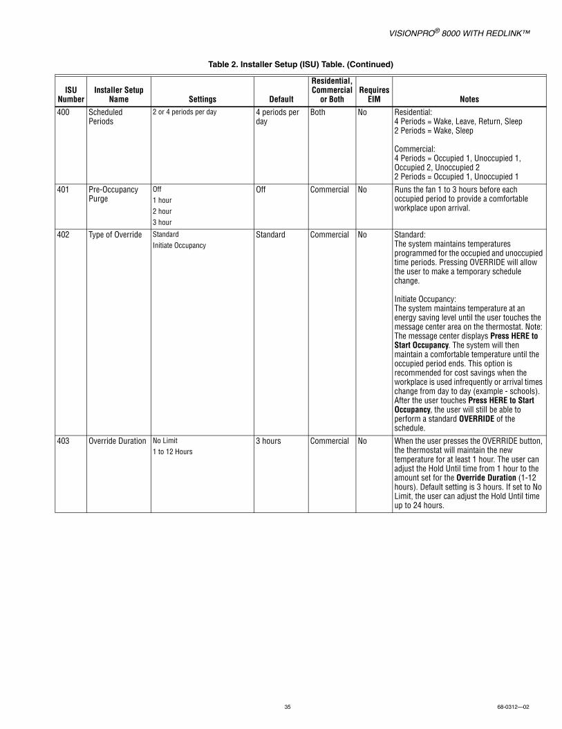
VISIONPRO® 8000 WITH REDLINK™
35 68-0312—02
400 Scheduled Periods
2 or 4 periods per day 4 periods per day
Both No Residential:4 Periods = Wake, Leave, Return, Sleep2 Periods = Wake, Sleep
Commercial:4 Periods = Occupied 1, Unoccupied 1, Occupied 2, Unoccupied 22 Periods = Occupied 1, Unoccupied 1
401 Pre-Occupancy Purge
Off1 hour2 hour3 hour
Off Commercial No Runs the fan 1 to 3 hours before each occupied period to provide a comfortable workplace upon arrival.
402 Type of Override StandardInitiate Occupancy
Standard Commercial No Standard:The system maintains temperatures programmed for the occupied and unoccupied time periods. Pressing OVERRIDE will allow the user to make a temporary schedule change.
Initiate Occupancy:The system maintains temperature at an energy saving level until the user touches the message center area on the thermostat. Note: The message center displays Press HERE to Start Occupancy. The system will then maintain a comfortable temperature until the occupied period ends. This option is recommended for cost savings when the workplace is used infrequently or arrival times change from day to day (example - schools). After the user touches Press HERE to Start Occupancy, the user will still be able to perform a standard OVERRIDE of the schedule.
403 Override Duration No Limit1 to 12 Hours
3 hours Commercial No When the user presses the OVERRIDE button, the thermostat will maintain the new temperature for at least 1 hour. The user can adjust the Hold Until time from 1 hour to the amount set for the Override Duration (1-12 hours). Default setting is 3 hours. If set to No Limit, the user can adjust the Hold Until time up to 24 hours.
Table 2. Installer Setup (ISU) Table. (Continued)
ISU Number
Installer Setup Name Settings Default
Residential, Commercial
or BothRequires
EIM Notes
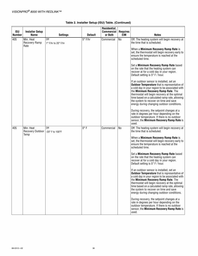
VISIONPRO® 8000 WITH REDLINK™
68-0312—02 36
405 Min. Heat Recovery Ramp Rate
Off1° F/hr to 20° F/hr
5° F/hr Commercial No Off: The heating system will begin recovery at the time that is scheduled.
When a Minimum Recovery Ramp Rate is set, the thermostat will begin recovery early to ensure the temperature is reached at the scheduled time.
Set a Minimum Recovery Ramp Rate based on the rate that the heating system can recover at for a cold day in your region. Default setting is 5° F / hour.
If an outdoor sensor is installed, set an Outdoor Temperature that is representative of a cold day in your region to be associated with the Minimum Recovery Ramp Rate. The thermostat will begin recovery at the optimal time based on a calculated ramp rate, allowing the system to recover on time and save energy during changing outdoor conditions.
During recovery, the setpoint changes at a rate in degrees per hour depending on the outdoor temperature. If there is no outdoor sensor, the Minimum Recovery Ramp Rate is used.
405 Min. Heat Recovery Outdoor Temp
Off-20° F to 100°F
0° F Commercial No Off: The heating system will begin recovery at the time that is scheduled.
When a Minimum Recovery Ramp Rate is set, the thermostat will begin recovery early to ensure the temperature is reached at the scheduled time.
Set a Minimum Recovery Ramp Rate based on the rate that the heating system can recover at for a cold day in your region. Default setting is 5° F / hour.
If an outdoor sensor is installed, set an Outdoor Temperature that is representative of a cold day in your region to be associated with the Minimum Recovery Ramp Rate. The thermostat will begin recovery at the optimal time based on a calculated ramp rate, allowing the system to recover on time and save energy during changing outdoor conditions.
During recovery, the setpoint changes at a rate in degrees per hour depending on the outdoor temperature. If there is no outdoor sensor, the Minimum Recovery Ramp Rate is used.
Table 2. Installer Setup (ISU) Table. (Continued)
ISU Number
Installer Setup Name Settings Default
Residential, Commercial
or BothRequires
EIM Notes
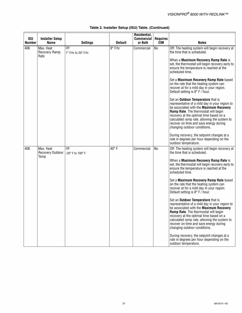
VISIONPRO® 8000 WITH REDLINK™
37 68-0312—02
406 Max. Heat Recovery Ramp Rate
Off1° F/hr to 20° F/hr
8° F/hr Commercial No Off: The heating system will begin recovery at the time that is scheduled.
When a Maximum Recovery Ramp Rate is set, the thermostat will begin recovery early to ensure the temperature is reached at the scheduled time.
Set a Maximum Recovery Ramp Rate based on the rate that the heating system can recover at for a mild day in your region. Default setting is 8° F / hour.
Set an Outdoor Temperature that is representative of a mild day in your region to be associated with the Maximum Recovery Ramp Rate. The thermostat will begin recovery at the optimal time based on a calculated ramp rate, allowing the system to recover on time and save energy during changing outdoor conditions.
During recovery, the setpoint changes at a rate in degrees per hour depending on the outdoor temperature.
406 Max. Heat Recovery Outdoor Temp
Off-20° F to 100° F
40° F Commercial No Off: The heating system will begin recovery at the time that is scheduled.
When a Maximum Recovery Ramp Rate is set, the thermostat will begin recovery early to ensure the temperature is reached at the scheduled time.
Set a Maximum Recovery Ramp Rate based on the rate that the heating system can recover at for a mild day in your region. Default setting is 8° F / hour.
Set an Outdoor Temperature that is representative of a mild day in your region to be associated with the Maximum Recovery Ramp Rate. The thermostat will begin recovery at the optimal time based on a calculated ramp rate, allowing the system to recover on time and save energy during changing outdoor conditions.
During recovery, the setpoint changes at a rate in degrees per hour depending on the outdoor temperature.
Table 2. Installer Setup (ISU) Table. (Continued)
ISU Number
Installer Setup Name Settings Default
Residential, Commercial
or BothRequires
EIM Notes

VISIONPRO® 8000 WITH REDLINK™
68-0312—02 38
407 Min. Cool Recovery Ramp Rate
Off1° F/hr to 20° F/hr
3° F/hr Commercial No Off: The cooling system will begin recovery at the time that is scheduled.
When a Minimum Recovery Ramp Rate is set, the thermostat will begin recovery early to ensure the temperature is reached at the scheduled time.
Set a Minimum Recovery Ramp Rate based on the rate that the cooling system can recover at for a hot day in your region. Default setting is 3° F / hour.
If an outdoor sensor is installed, set an Outdoor Temperature that is representative of a hot day in your region to be associated with the Minimum Recovery Ramp Rate. The thermostat will begin recovery at the optimal time based on a calculated ramp rate, allowing the system to recover on time and save energy during changing outdoor conditions.
During recovery, the setpoint changes at a rate in degrees per hour depending on the outdoor temperature. If there is no outdoor sensor, the Minimum Recovery Ramp Rate is used.
407 Min. Cool Recovery Outdoor Temp
Off-20° F to 100° F
90° F Commercial No Off: The cooling system will begin recovery at the time that is scheduled.
When a Minimum Recovery Ramp Rate is set, the thermostat will begin recovery early to ensure the temperature is reached at the scheduled time.
Set a Minimum Recovery Ramp Rate based on the rate that the cooling system can recover at for a hot day in your region. Default setting is 3° F / hour.
If an outdoor sensor is installed, set an Outdoor Temperature that is representative of a hot day in your region to be associated with the Minimum Recovery Ramp Rate. The thermostat will begin recovery at the optimal time based on a calculated ramp rate, allowing the system to recover on time and save energy during changing outdoor conditions.
During recovery, the setpoint changes at a rate in degrees per hour depending on the outdoor temperature. If there is no outdoor sensor, the Minimum Recovery Ramp Rate is used.
Table 2. Installer Setup (ISU) Table. (Continued)
ISU Number
Installer Setup Name Settings Default
Residential, Commercial
or BothRequires
EIM Notes
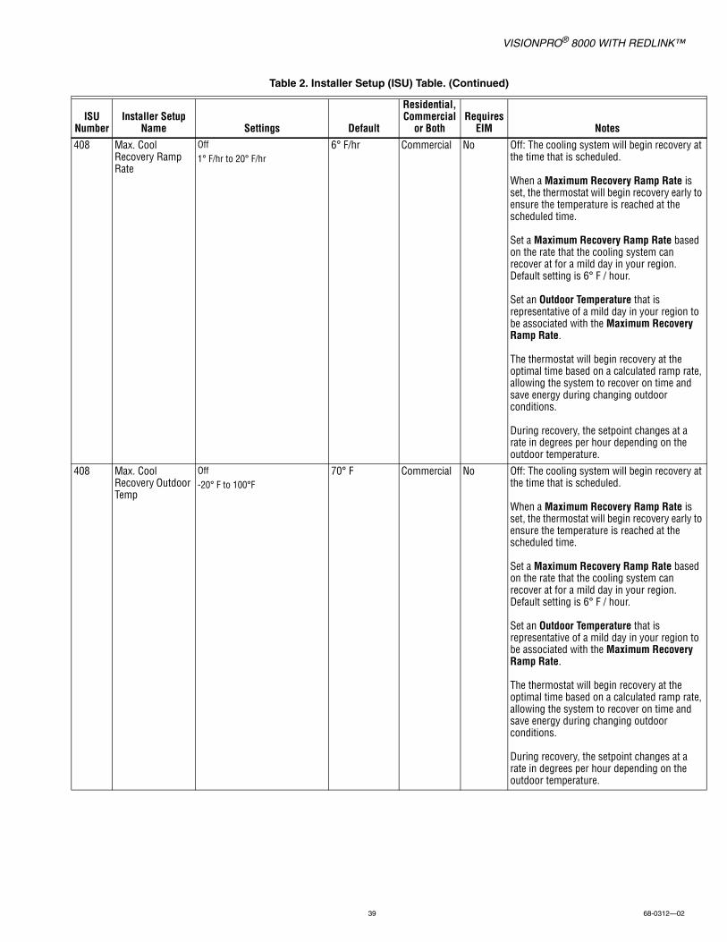
VISIONPRO® 8000 WITH REDLINK™
39 68-0312—02
408 Max. Cool Recovery Ramp Rate
Off1° F/hr to 20° F/hr
6° F/hr Commercial No Off: The cooling system will begin recovery at the time that is scheduled.
When a Maximum Recovery Ramp Rate is set, the thermostat will begin recovery early to ensure the temperature is reached at the scheduled time.
Set a Maximum Recovery Ramp Rate based on the rate that the cooling system can recover at for a mild day in your region. Default setting is 6° F / hour.
Set an Outdoor Temperature that is representative of a mild day in your region to be associated with the Maximum Recovery Ramp Rate.
The thermostat will begin recovery at the optimal time based on a calculated ramp rate, allowing the system to recover on time and save energy during changing outdoor conditions.
During recovery, the setpoint changes at a rate in degrees per hour depending on the outdoor temperature.
408 Max. Cool Recovery Outdoor Temp
Off-20° F to 100°F
70° F Commercial No Off: The cooling system will begin recovery at the time that is scheduled.
When a Maximum Recovery Ramp Rate is set, the thermostat will begin recovery early to ensure the temperature is reached at the scheduled time.
Set a Maximum Recovery Ramp Rate based on the rate that the cooling system can recover at for a mild day in your region. Default setting is 6° F / hour.
Set an Outdoor Temperature that is representative of a mild day in your region to be associated with the Maximum Recovery Ramp Rate.
The thermostat will begin recovery at the optimal time based on a calculated ramp rate, allowing the system to recover on time and save energy during changing outdoor conditions.
During recovery, the setpoint changes at a rate in degrees per hour depending on the outdoor temperature.
Table 2. Installer Setup (ISU) Table. (Continued)
ISU Number
Installer Setup Name Settings Default
Residential, Commercial
or BothRequires
EIM Notes
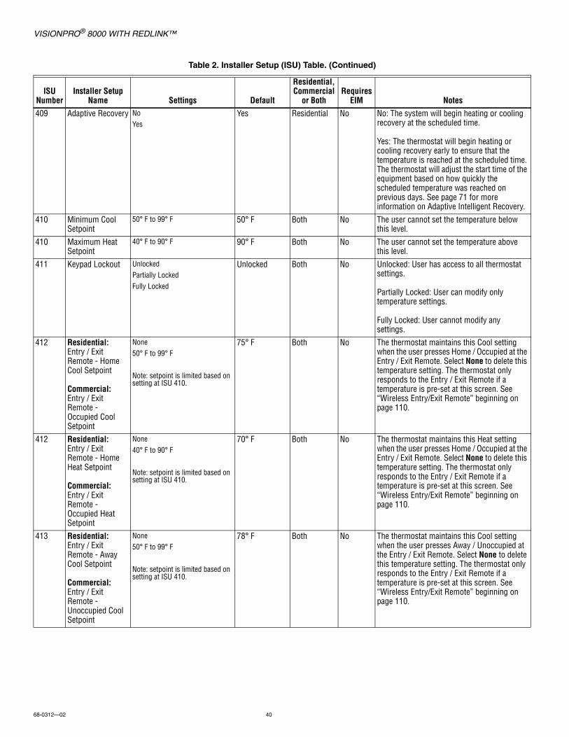
VISIONPRO® 8000 WITH REDLINK™
68-0312—02 40
409 Adaptive Recovery NoYes
Yes Residential No No: The system will begin heating or cooling recovery at the scheduled time.
Yes: The thermostat will begin heating or cooling recovery early to ensure that the temperature is reached at the scheduled time. The thermostat will adjust the start time of the equipment based on how quickly the scheduled temperature was reached on previous days. See page 71 for more information on Adaptive Intelligent Recovery.
410 Minimum Cool Setpoint
50° F to 99° F 50° F Both No The user cannot set the temperature below this level.
410 Maximum Heat Setpoint
40° F to 90° F 90° F Both No The user cannot set the temperature above this level.
411 Keypad Lockout UnlockedPartially LockedFully Locked
Unlocked Both No Unlocked: User has access to all thermostat settings.
Partially Locked: User can modify only temperature settings.
Fully Locked: User cannot modify any settings.
412 Residential:Entry / Exit Remote - Home Cool Setpoint
Commercial:Entry / Exit Remote - Occupied Cool Setpoint
None50° F to 99° F
Note: setpoint is limited based on setting at ISU 410.
75° F Both No The thermostat maintains this Cool setting when the user presses Home / Occupied at the Entry / Exit Remote. Select None to delete this temperature setting. The thermostat only responds to the Entry / Exit Remote if a temperature is pre-set at this screen. See “Wireless Entry/Exit Remote” beginning on page 110.
412 Residential:Entry / Exit Remote - Home Heat Setpoint
Commercial:Entry / Exit Remote - Occupied Heat Setpoint
None40° F to 90° F
Note: setpoint is limited based on setting at ISU 410.
70° F Both No The thermostat maintains this Heat setting when the user presses Home / Occupied at the Entry / Exit Remote. Select None to delete this temperature setting. The thermostat only responds to the Entry / Exit Remote if a temperature is pre-set at this screen. See “Wireless Entry/Exit Remote” beginning on page 110.
413 Residential:Entry / Exit Remote - Away Cool Setpoint
Commercial:Entry / Exit Remote - Unoccupied Cool Setpoint
None50° F to 99° F
Note: setpoint is limited based on setting at ISU 410.
78° F Both No The thermostat maintains this Cool setting when the user presses Away / Unoccupied at the Entry / Exit Remote. Select None to delete this temperature setting. The thermostat only responds to the Entry / Exit Remote if a temperature is pre-set at this screen. See “Wireless Entry/Exit Remote” beginning on page 110.
Table 2. Installer Setup (ISU) Table. (Continued)
ISU Number
Installer Setup Name Settings Default
Residential, Commercial
or BothRequires
EIM Notes
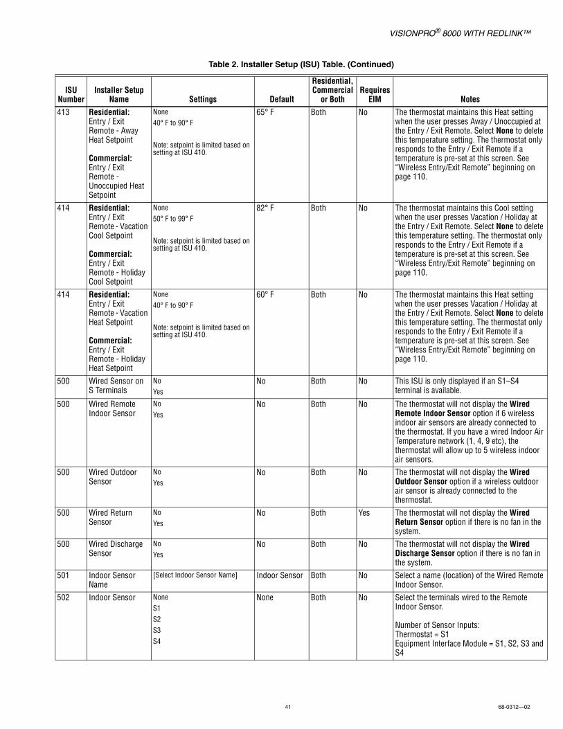
VISIONPRO® 8000 WITH REDLINK™
41 68-0312—02
413 Residential:Entry / Exit Remote - Away Heat Setpoint
Commercial:Entry / Exit Remote - Unoccupied Heat Setpoint
None40° F to 90° F
Note: setpoint is limited based on setting at ISU 410.
65° F Both No The thermostat maintains this Heat setting when the user presses Away / Unoccupied at the Entry / Exit Remote. Select None to delete this temperature setting. The thermostat only responds to the Entry / Exit Remote if a temperature is pre-set at this screen. See “Wireless Entry/Exit Remote” beginning on page 110.
414 Residential:Entry / Exit Remote - Vacation Cool Setpoint
Commercial:Entry / Exit Remote - Holiday Cool Setpoint
None50° F to 99° F
Note: setpoint is limited based on setting at ISU 410.
82° F Both No The thermostat maintains this Cool setting when the user presses Vacation / Holiday at the Entry / Exit Remote. Select None to delete this temperature setting. The thermostat only responds to the Entry / Exit Remote if a temperature is pre-set at this screen. See “Wireless Entry/Exit Remote” beginning on page 110.
414 Residential:Entry / Exit Remote - Vacation Heat Setpoint
Commercial:Entry / Exit Remote - Holiday Heat Setpoint
None40° F to 90° F
Note: setpoint is limited based on setting at ISU 410.
60° F Both No The thermostat maintains this Heat setting when the user presses Vacation / Holiday at the Entry / Exit Remote. Select None to delete this temperature setting. The thermostat only responds to the Entry / Exit Remote if a temperature is pre-set at this screen. See “Wireless Entry/Exit Remote” beginning on page 110.
500 Wired Sensor on S Terminals
NoYes
No Both No This ISU is only displayed if an S1–S4 terminal is available.
500 Wired Remote Indoor Sensor
NoYes
No Both No The thermostat will not display the Wired Remote Indoor Sensor option if 6 wireless indoor air sensors are already connected to the thermostat. If you have a wired Indoor Air Temperature network (1, 4, 9 etc), the thermostat will allow up to 5 wireless indoor air sensors.
500 Wired Outdoor Sensor
NoYes
No Both No The thermostat will not display the Wired Outdoor Sensor option if a wireless outdoor air sensor is already connected to the thermostat.
500 Wired Return Sensor
NoYes
No Both Yes The thermostat will not display the Wired Return Sensor option if there is no fan in the system.
500 Wired Discharge Sensor
NoYes
No Both No The thermostat will not display the Wired Discharge Sensor option if there is no fan in the system.
501 Indoor Sensor Name
[Select Indoor Sensor Name] Indoor Sensor Both No Select a name (location) of the Wired Remote Indoor Sensor.
502 Indoor Sensor NoneS1S2S3S4
None Both No Select the terminals wired to the Remote Indoor Sensor.
Number of Sensor Inputs:Thermostat = S1Equipment Interface Module = S1, S2, S3 and S4
Table 2. Installer Setup (ISU) Table. (Continued)
ISU Number
Installer Setup Name Settings Default
Residential, Commercial
or BothRequires
EIM Notes
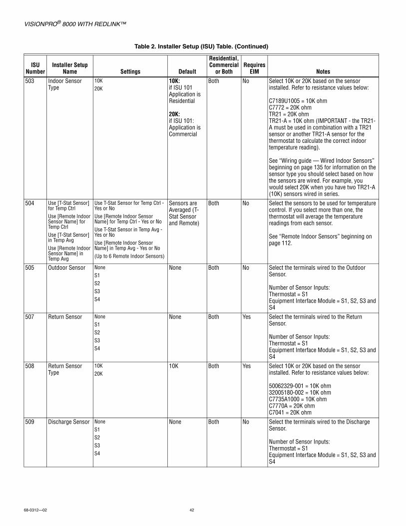
VISIONPRO® 8000 WITH REDLINK™
68-0312—02 42
503 Indoor Sensor Type
10K20K
10K:if ISU 101 Application is Residential
20K:if ISU 101: Application is Commercial
Both No Select 10K or 20K based on the sensor installed. Refer to resistance values below:
C7189U1005 = 10K ohmC7772 = 20K ohmTR21 = 20K ohmTR21-A = 10K ohm (IMPORTANT - the TR21-A must be used in combination with a TR21 sensor or another TR21-A sensor for the thermostat to calculate the correct indoor temperature reading).
See “Wiring guide — Wired Indoor Sensors” beginning on page 135 for information on the sensor type you should select based on how the sensors are wired. For example, you would select 20K when you have two TR21-A (10K) sensors wired in series.
504 Use [T-Stat Sensor] for Temp CtrlUse [Remote Indoor Sensor Name] for Temp CtrlUse [T-Stat Sensor] in Temp AvgUse [Remote Indoor Sensor Name] in Temp Avg
Use T-Stat Sensor for Temp Ctrl - Yes or NoUse [Remote Indoor Sensor Name] for Temp Ctrl - Yes or NoUse T-Stat Sensor in Temp Avg - Yes or NoUse [Remote Indoor Sensor Name] in Temp Avg - Yes or No(Up to 6 Remote Indoor Sensors)
Sensors are Averaged (T-Stat Sensor and Remote)
Both No Select the sensors to be used for temperature control. If you select more than one, the thermostat will average the temperature readings from each sensor.
See “Remote Indoor Sensors” beginning on page 112.
505 Outdoor Sensor NoneS1S2S3S4
None Both No Select the terminals wired to the Outdoor Sensor.
Number of Sensor Inputs:Thermostat = S1Equipment Interface Module = S1, S2, S3 and S4
507 Return Sensor NoneS1S2S3S4
None Both Yes Select the terminals wired to the Return Sensor.
Number of Sensor Inputs:Thermostat = S1Equipment Interface Module = S1, S2, S3 and S4
508 Return Sensor Type
10K20K
10K Both Yes Select 10K or 20K based on the sensor installed. Refer to resistance values below:
50062329-001 = 10K ohm32005180-002 = 10K ohmC7735A1000 = 10K ohmC7770A = 20K ohmC7041 = 20K ohm
509 Discharge Sensor NoneS1S2S3S4
None Both No Select the terminals wired to the Discharge Sensor.
Number of Sensor Inputs:Thermostat = S1Equipment Interface Module = S1, S2, S3 and S4
Table 2. Installer Setup (ISU) Table. (Continued)
ISU Number
Installer Setup Name Settings Default
Residential, Commercial
or BothRequires
EIM Notes
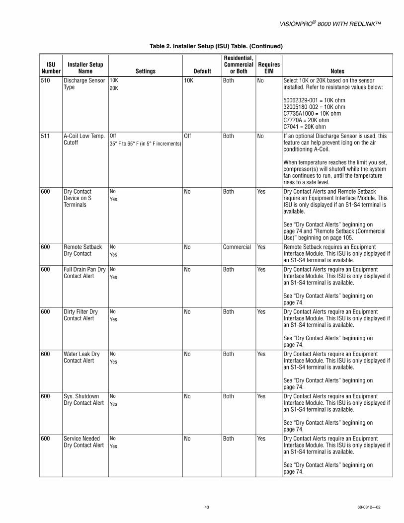
VISIONPRO® 8000 WITH REDLINK™
43 68-0312—02
510 Discharge Sensor Type
10K20K
10K Both No Select 10K or 20K based on the sensor installed. Refer to resistance values below:
50062329-001 = 10K ohm32005180-002 = 10K ohmC7735A1000 = 10K ohmC7770A = 20K ohmC7041 = 20K ohm
511 A-Coil Low Temp. Cutoff
Off35° F to 65° F (in 5° F increments)
Off Both No If an optional Discharge Sensor is used, this feature can help prevent icing on the air conditioning A-Coil.
When temperature reaches the limit you set, compressor(s) will shutoff while the system fan continues to run, until the temperature rises to a safe level.
600 Dry Contact Device on S Terminals
NoYes
No Both Yes Dry Contact Alerts and Remote Setback require an Equipment Interface Module. This ISU is only displayed if an S1-S4 terminal is available.
See “Dry Contact Alerts” beginning on page 74 and “Remote Setback (Commercial Use)” beginning on page 105.
600 Remote Setback Dry Contact
NoYes
No Commercial Yes Remote Setback requires an Equipment Interface Module. This ISU is only displayed if an S1-S4 terminal is available.
600 Full Drain Pan Dry Contact Alert
NoYes
No Both Yes Dry Contact Alerts require an Equipment Interface Module. This ISU is only displayed if an S1-S4 terminal is available.
See “Dry Contact Alerts” beginning on page 74.
600 Dirty Filter Dry Contact Alert
NoYes
No Both Yes Dry Contact Alerts require an Equipment Interface Module. This ISU is only displayed if an S1-S4 terminal is available.
See “Dry Contact Alerts” beginning on page 74.
600 Water Leak Dry Contact Alert
NoYes
No Both Yes Dry Contact Alerts require an Equipment Interface Module. This ISU is only displayed if an S1-S4 terminal is available.
See “Dry Contact Alerts” beginning on page 74.
600 Sys. Shutdown Dry Contact Alert
NoYes
No Both Yes Dry Contact Alerts require an Equipment Interface Module. This ISU is only displayed if an S1-S4 terminal is available.
See “Dry Contact Alerts” beginning on page 74.
600 Service Needed Dry Contact Alert
NoYes
No Both Yes Dry Contact Alerts require an Equipment Interface Module. This ISU is only displayed if an S1-S4 terminal is available.
See “Dry Contact Alerts” beginning on page 74.
Table 2. Installer Setup (ISU) Table. (Continued)
ISU Number
Installer Setup Name Settings Default
Residential, Commercial
or BothRequires
EIM Notes
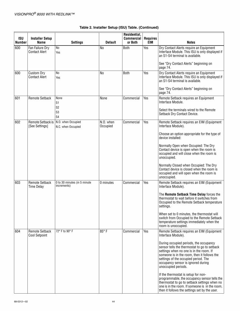
VISIONPRO® 8000 WITH REDLINK™
68-0312—02 44
600 Fan Failure Dry Contact Alert
NoYes
No Both Yes Dry Contact Alerts require an Equipment Interface Module. This ISU is only displayed if an S1-S4 terminal is available.
See “Dry Contact Alerts” beginning on page 74.
600 Custom Dry Contact Alert
NoYes
No Both Yes Dry Contact Alerts require an Equipment Interface Module. This ISU is only displayed if an S1-S4 terminal is available.
See “Dry Contact Alerts” beginning on page 74.
601 Remote Setback NoneS1S2S3S4
None Commercial Yes Remote Setback requires an Equipment Interface Module.
Select the terminals wired to the Remote Setback Dry Contact Device.
602 Remote Setback is [See Settings]
N.O. when OccupiedN.C. when Occupied
N.O. when Occupied
Commercial Yes Remote Setback requires an EIM (Equipment Interface Module).
Choose an option appropriate for the type of device installed:
Normally Open when Occupied: The Dry Contact device is open when the room is occupied and will close when the room is unoccupied.
Normally Closed when Occupied: The Dry Contact device is closed when the room is occupied and will open when the room is unoccupied.
603 Remote Setback Time Delay
0 to 30 minutes (in 5 minute increments)
0 minutes Commercial Yes Remote Setback requires an EIM (Equipment Interface Module).
The Remote Setback Time Delay forces the thermostat to wait before it switches from Occupied to the Remote Setback temperature settings.
When set to 0 minutes, the thermostat will switch from Occupied to the Remote Setback temperature settings immediately when the room is unoccupied.
604 Remote Setback Cool Setpoint
72° F to 90° F 85° F Commercial Yes Remote Setback requires an EIM (Equipment Interface Module).
During occupied periods, the occupancy sensor tells the thermostat to go to setback settings when no one is in the room. If someone is in the room, then it follows the settings of the occupied period. The occupancy sensor is ignored during unoccupied periods.
If the thermostat is setup for non-programmable, the occupancy sensor tells the thermostat to go to setback settings when no one is in the room. If someone is in the room, then it follows the settings set by the user.
Table 2. Installer Setup (ISU) Table. (Continued)
ISU Number
Installer Setup Name Settings Default
Residential, Commercial
or BothRequires
EIM Notes

VISIONPRO® 8000 WITH REDLINK™
45 68-0312—02
604 Remote Setback Heat Setpoint
50° F to 70° F 64° F Commercial Yes Remote Setback requires an EIM (Equipment Interface Module).
During occupied periods, the occupancy sensor tells the thermostat to go to setback settings when no one is in the room. If someone is in the room, then it follows the settings of the occupied period. The occupancy sensor is ignored during unoccupied periods.
If the thermostat is setup for non-programmable, the occupancy sensor tells the thermostat to go to setback settings when no one is in the room. If someone is in the room, then it follows the settings set by the user.
605 Drain Pan Alert NoneS1S2S3S4
None Both Yes Dry Contact Alerts require an Equipment Interface Module.
Select the terminals wired to the Full Drain Pan Dry Contact Device.
606 Drain Pan Alert is [See Settings]
Normally Open Normally Closed
Normally Open Both Yes Dry Contact Alerts require an EIM (Equipment Interface Module).
Choose an option appropriate for the type of device installed.
Normally Open: The Dry Contact device is normally open and will close when the device detects the drain pan is full.
Normally Closed: The Dry Contact device is normally closed and will open when the device detects the drain pan is full.
607 Dirty Filter Alert NoneS1S2S3S4
None Both Yes Dry Contact Alerts require an Equipment Interface Module.
Select the terminals wired to the Dirty Filter Dry Contact Device.
608 Dirty Filtr Alert is [See Settings]
Normally OpenNormally Closed
Normally Open Both Yes Dry Contact Alerts require an EIM (Equipment Interface Module).
Choose an option appropriate for the type of device installed:
Normally Open: The Dry Contact device is normally open and will close when the device detects a dirty filter.
Normally Closed: The Dry Contact device is normally closed and will open when the device detects a dirty filter.
609 Water Leak Alert NoneS1S2S3S4
None Both Yes Dry Contact Alerts require an Equipment Interface Module.
Select the terminals wired to the Water Leak Dry Contact Device (wet switch).
Table 2. Installer Setup (ISU) Table. (Continued)
ISU Number
Installer Setup Name Settings Default
Residential, Commercial
or BothRequires
EIM Notes
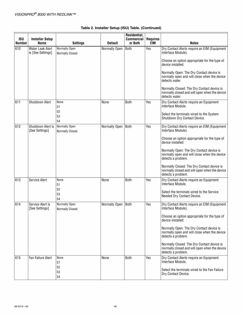
VISIONPRO® 8000 WITH REDLINK™
68-0312—02 46
610 Water Leak Alert is [See Settings]
Normally OpenNormally Closed
Normally Open Both Yes Dry Contact Alerts require an EIM (Equipment Interface Module).
Choose an option appropriate for the type of device installed:
Normally Open: The Dry Contact device is normally open and will close when the device detects water.
Normally Closed: The Dry Contact device is normally closed and will open when the device detects water.
611 Shutdown Alert NoneS1S2S3S4
None Both Yes Dry Contact Alerts require an Equipment Interface Module.
Select the terminals wired to the System Shutdown Dry Contact Device.
612 Shutdown Alert is [See Settings]
Normally OpenNormally Closed
Normally Open Both Yes Dry Contact Alerts require an EIM (Equipment Interface Module).
Choose an option appropriate for the type of device installed:
Normally Open: The Dry Contact device is normally open and will close when the device detects a problem.
Normally Closed: The Dry Contact device is normally closed and will open when the device detects a problem.
613 Service Alert NoneS1S2S3S4
None Both Yes Dry Contact Alerts require an Equipment Interface Module.
Select the terminals wired to the Service Needed Dry Contact Device.
614 Service Alert is [See Settings]
Normally OpenNormally Closed
Normally Open Both Yes Dry Contact Alerts require an EIM (Equipment Interface Module).
Choose an option appropriate for the type of device installed:
Normally Open: The Dry Contact device is normally open and will close when the device detects a problem.
Normally Closed: The Dry Contact device is normally closed and will open when the device detects a problem.
615 Fan Failure Alert NoneS1S2S3S4
None Both Yes Dry Contact Alerts require an Equipment Interface Module.
Select the terminals wired to the Fan Failure Dry Contact Device.
Table 2. Installer Setup (ISU) Table. (Continued)
ISU Number
Installer Setup Name Settings Default
Residential, Commercial
or BothRequires
EIM Notes

VISIONPRO® 8000 WITH REDLINK™
47 68-0312—02
616 Fan Failure Alert is [See Settings]
N.O. when Fan RunsN.C. when Fan Runs
N.C. when Fan Runs
Both Yes Dry Contact Alerts require an EIM (Equipment Interface Module).
Choose an option appropriate for the type of device installed:
Normally Open when Fan is Running: The Dry Contact device is open when the fan is running and will close when the fan is not running.
Normally Closed when Fan is Running: The Dry Contact device is closed when the fan is running and will open when the fan is not running.
617 Custom Alert NoneS1S2S3S4
None Both Yes Dry Contact Alerts require an Equipment Interface Module.
Select the terminals wired to the Custom Dry Contact Device.
618 Custom Alert is [See Settings]
Normally OpenNormally Closed
Normally Open Both Yes Dry Contact Alerts require an EIM (Equipment Interface Module).
Choose an option appropriate for the type of device installed:
Normally Open: The Dry Contact device is normally open and will close when the device detects a problem.
Normally Closed: The Dry Contact device is normally closed and will open when the device detects a problem.
619 Custom Alert Name
View/Edit Custom Alert View/Edit Custom Alert
Both Yes Dry Contact Alerts require an EIM (Equipment Interface Module).
Enter a name for the custom alert dry contact. The thermostat displays this name including a brief message (entered on the next screen - ISU 620) when a dry contact device detects a problem.
620 Cust Alert Message
View/Edit Custom Alert View/Edit Custom Alert
Both Yes Dry Contact Alerts require an EIM (Equipment Interface Module).
Enter a message for the custom alert dry contact. The thermostat displays this message when a dry contact device detects a problem.
700 Filter Type NoneElec. Air CleanerMedia
Media Both No
702 Number of Air Filters
1 to 2 1 Both No
Table 2. Installer Setup (ISU) Table. (Continued)
ISU Number
Installer Setup Name Settings Default
Residential, Commercial
or BothRequires
EIM Notes

VISIONPRO® 8000 WITH REDLINK™
68-0312—02 48
711 Air Filter 1 Reminder
Note: “1” is not displayed if there is only 1 filter.
Off
Run Time:10, 20, 30, 45, 60, 90, 120, 150 days
Calendar:30, 45, 60, 75 days3, 4, 5, 6, 9, 12, 15 months
Off Both No
711 Air Filter 2 Reminder
Off
Run Time:10, 20, 30, 45, 60, 90, 120, 150 days
Calendar:30, 45, 60, 75 days3, 4, 5, 6, 9, 12, 15 months
Off Both No
712 EAC Cell Reminder
Off
Calendar Months:6, 7, 8, 9, 10, 11, 12 months
Off Both No Electronic Air Cleaner Cell Cleaning Reminder
712 EAC Pre-Filter Reminder
Off
Calendar Months:3, 4, 5, 6 months
Off Both No Electronic Air Cleaner Pre-Filter Cleaning Reminder
712 EAC Post Filter Reminder
Off
Calendar Months:6, 7, 8, 9, 10, 11, 12 months
Off Both No Electronic Air Cleaner Post-Filter Replacement Reminder
800 Humidifier Type NoneSteamBypass / Fan Pwrd
None Both No
801 Sensor for Hum T-Stat SensorRemote Indoor Sensor NameRemote Indoor Sensor NameRemote Indoor Sensor NameRemote Indoor Sensor NameRemote Indoor Sensor NameRemote Indoor Sensor Name
(Up to 6 Remote Indoor Sensors)
T-Stat Sensor Both No Select a sensor to control humidification (thermostat or an optional remote sensor). If multiple sensors are installed, you can use a different sensor for dehumidification control. See “Humidification control” beginning on page 112.
Note: Humidity sensing cannot be averaged.
803 Humidifier Wiring NoneU1U2U3
Thermostat defaults to the next unused universal terminal (U1, U2, U3).
Both No Number of Universal Outputs:TH8321 Thermostat: U1 terminalsEquipment Interface Module (EIM): U1, U2 and U3 terminals
U1, U2, U3 are dry contacts that require power. See “Wiring IAQ Equipment or a Heat/Cool Stage to the Universal Terminals” beginning on page 129.
Table 2. Installer Setup (ISU) Table. (Continued)
ISU Number
Installer Setup Name Settings Default
Residential, Commercial
or BothRequires
EIM Notes
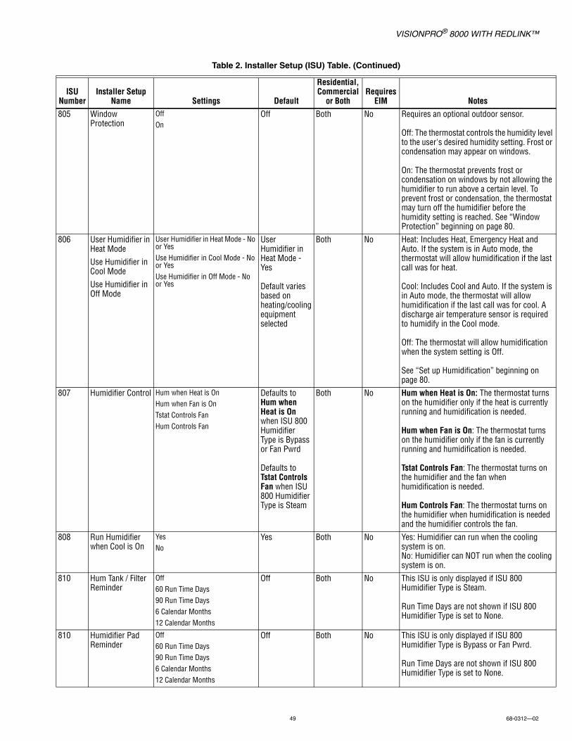
VISIONPRO® 8000 WITH REDLINK™
49 68-0312—02
805 Window Protection
OffOn
Off Both No Requires an optional outdoor sensor.
Off: The thermostat controls the humidity level to the user's desired humidity setting. Frost or condensation may appear on windows.
On: The thermostat prevents frost or condensation on windows by not allowing the humidifier to run above a certain level. To prevent frost or condensation, the thermostat may turn off the humidifier before the humidity setting is reached. See “Window Protection” beginning on page 80.
806 User Humidifier in Heat Mode
Use Humidifier in Cool Mode
Use Humidifier in Off Mode
User Humidifier in Heat Mode - No or YesUse Humidifier in Cool Mode - No or YesUse Humidifier in Off Mode - No or Yes
User Humidifier in Heat Mode - Yes
Default varies based on heating/cooling equipment selected
Both No Heat: Includes Heat, Emergency Heat and Auto. If the system is in Auto mode, the thermostat will allow humidification if the last call was for heat.
Cool: Includes Cool and Auto. If the system is in Auto mode, the thermostat will allow humidification if the last call was for cool. A discharge air temperature sensor is required to humidify in the Cool mode.
Off: The thermostat will allow humidification when the system setting is Off.
See “Set up Humidification” beginning on page 80.
807 Humidifier Control Hum when Heat is OnHum when Fan is OnTstat Controls FanHum Controls Fan
Defaults to Hum when Heat is Onwhen ISU 800 Humidifier Type is Bypass or Fan Pwrd
Defaults to Tstat Controls Fan when ISU 800 Humidifier Type is Steam
Both No Hum when Heat is On: The thermostat turns on the humidifier only if the heat is currently running and humidification is needed.
Hum when Fan is On: The thermostat turns on the humidifier only if the fan is currently running and humidification is needed.
Tstat Controls Fan: The thermostat turns on the humidifier and the fan when humidification is needed.
Hum Controls Fan: The thermostat turns on the humidifier when humidification is needed and the humidifier controls the fan.
808 Run Humidifier when Cool is On
YesNo
Yes Both No Yes: Humidifier can run when the cooling system is on.No: Humidifier can NOT run when the cooling system is on.
810 Hum Tank / Filter Reminder
Off60 Run Time Days90 Run Time Days6 Calendar Months12 Calendar Months
Off Both No This ISU is only displayed if ISU 800 Humidifier Type is Steam.
Run Time Days are not shown if ISU 800 Humidifier Type is set to None.
810 Humidifier Pad Reminder
Off60 Run Time Days90 Run Time Days6 Calendar Months12 Calendar Months
Off Both No This ISU is only displayed if ISU 800 Humidifier Type is Bypass or Fan Pwrd.
Run Time Days are not shown if ISU 800 Humidifier Type is set to None.
Table 2. Installer Setup (ISU) Table. (Continued)
ISU Number
Installer Setup Name Settings Default
Residential, Commercial
or BothRequires
EIM Notes

VISIONPRO® 8000 WITH REDLINK™
68-0312—02 50
900 Dehumidification Equipment
Residential:NoneA/C with Low FanA/C with High FanDehumidifierCommercial:NoneA/C with Low FanA/C with High FanHot Gas BypassDehumidifier
None Both No See “Dehumidification - Residential” beginning on page 83 or “Dehumidification - Commercial” beginning on page 87.
901 Sensor for Dehum Change to:T-Stat SensorRemote Indoor Sensor NameRemote Indoor Sensor NameRemote Indoor Sensor NameRemote Indoor Sensor NameRemote Indoor Sensor NameRemote Indoor Sensor Name(Up to 6 Remote Indoor Sensors)
T-Stat Sensor Both No Select a sensor to control dehumidification (thermostat or an optional remote sensor). If multiple sensors are installed, you can use a different sensor for humidification control. See “Dehumidification control” beginning on page 112.
Note: Humidity sensing cannot be averaged.
902 Humidity Sensor on Home Screen
HumDehum
Hum Both No This ISU is only displayed when separate humidity sensors are used to control humidification and dehumidification. Only one of the sensors can be displayed on the home screen. Select either the Humidification Sensor or the Dehumidification Sensor.
904 Dehum Wiring NoneU1U2U3
Thermostat defaults to the next unused universal terminal (U1, U2, U3).
Both No Number of Universal Outputs:TH8321 Thermostat: U1 terminals Equipment Interface Module (EIM): U1, U2 and U3 terminals
U1, U2, U3 are dry contacts that require power. See “Wiring IAQ Equipment or a Heat/Cool Stage to the Universal Terminals” beginning on page 129.
905 Dehum Terminal - U1Dehum Terminal - U2Dehum Terminal - U3
Note: The U terminal shown on the screen depends on the terminal you selected at ISU 904 (Dehum Wiring).
Normally ClosedNormally Open
Defaults to Normally Closed when ISU 900 Dehum Equipment is A/C with Low Fan
Defaults to Normally Open when ISU 900 Dehum Equipment is Hot Gas Bypass
Both No Choose an option appropriate for the type of equipment installed.
Normally Open: U1, U2 or U3 will normally be open and will close when the thermostat calls for dehumidification.
Normally Closed: U1, U2 or U3 will normally be closed and will open when the thermostat calls for dehumidification.
Number of Universal Outputs:TH8321 Thermostat: U1 terminalsEquipment Interface Module (EIM): U1, U2 and U3 terminals
Table 2. Installer Setup (ISU) Table. (Continued)
ISU Number
Installer Setup Name Settings Default
Residential, Commercial
or BothRequires
EIM Notes
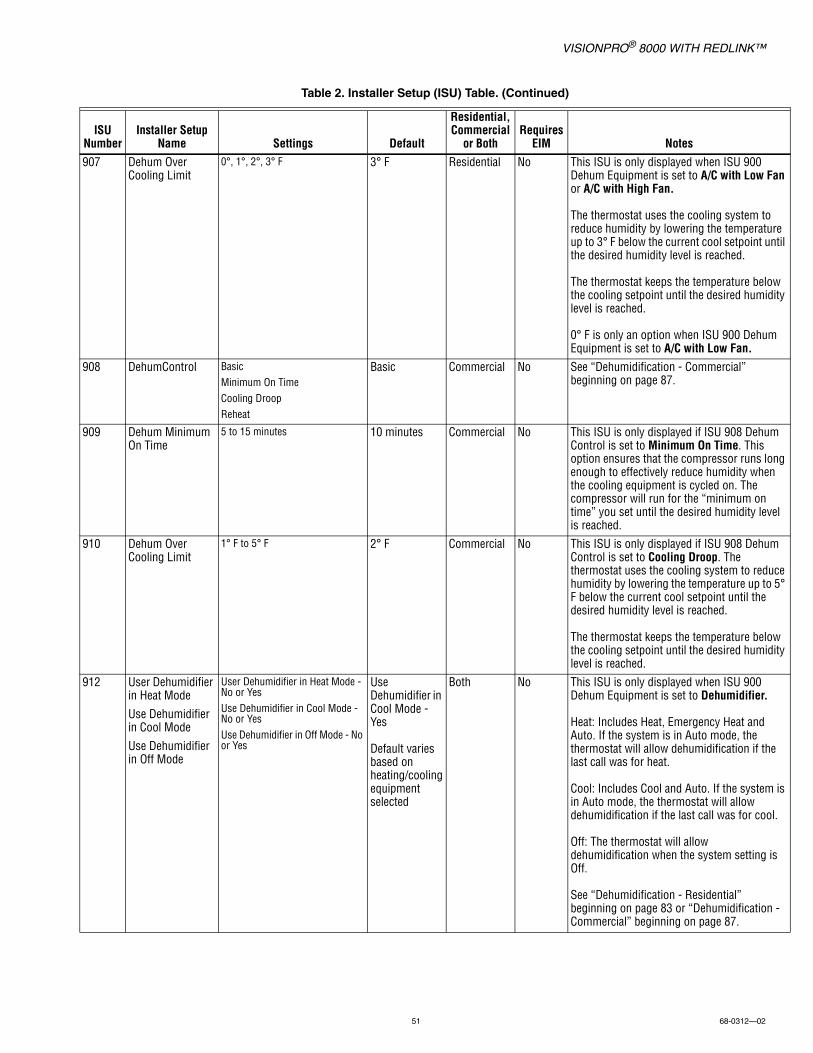
VISIONPRO® 8000 WITH REDLINK™
51 68-0312—02
907 Dehum Over Cooling Limit
0°, 1°, 2°, 3° F 3° F Residential No This ISU is only displayed when ISU 900 Dehum Equipment is set to A/C with Low Fan or A/C with High Fan.
The thermostat uses the cooling system to reduce humidity by lowering the temperature up to 3° F below the current cool setpoint until the desired humidity level is reached.
The thermostat keeps the temperature below the cooling setpoint until the desired humidity level is reached.
0° F is only an option when ISU 900 Dehum Equipment is set to A/C with Low Fan.
908 DehumControl BasicMinimum On TimeCooling DroopReheat
Basic Commercial No See “Dehumidification - Commercial” beginning on page 87.
909 Dehum Minimum On Time
5 to 15 minutes 10 minutes Commercial No This ISU is only displayed if ISU 908 Dehum Control is set to Minimum On Time. This option ensures that the compressor runs long enough to effectively reduce humidity when the cooling equipment is cycled on. The compressor will run for the “minimum on time” you set until the desired humidity level is reached.
910 Dehum Over Cooling Limit
1° F to 5° F 2° F Commercial No This ISU is only displayed if ISU 908 Dehum Control is set to Cooling Droop. The thermostat uses the cooling system to reduce humidity by lowering the temperature up to 5° F below the current cool setpoint until the desired humidity level is reached.
The thermostat keeps the temperature below the cooling setpoint until the desired humidity level is reached.
912 User Dehumidifier in Heat Mode
Use Dehumidifier in Cool Mode
Use Dehumidifier in Off Mode
User Dehumidifier in Heat Mode - No or YesUse Dehumidifier in Cool Mode - No or YesUse Dehumidifier in Off Mode - No or Yes
Use Dehumidifier in Cool Mode - Yes
Default varies based on heating/cooling equipment selected
Both No This ISU is only displayed when ISU 900 Dehum Equipment is set to Dehumidifier.
Heat: Includes Heat, Emergency Heat and Auto. If the system is in Auto mode, the thermostat will allow dehumidification if the last call was for heat.
Cool: Includes Cool and Auto. If the system is in Auto mode, the thermostat will allow dehumidification if the last call was for cool.
Off: The thermostat will allow dehumidification when the system setting is Off.
See “Dehumidification - Residential” beginning on page 83 or “Dehumidification - Commercial” beginning on page 87.
Table 2. Installer Setup (ISU) Table. (Continued)
ISU Number
Installer Setup Name Settings Default
Residential, Commercial
or BothRequires
EIM Notes

VISIONPRO® 8000 WITH REDLINK™
68-0312—02 52
913 Dehum Fan Control
Tstat Controls FanEquip Controls Fan
Tstat Controls Fan
Both No This ISU is only displayed when ISU 900 Dehum Equipment is set to Dehumidifier.
Tstat Controls Fan: The thermostat turns on the dehumidifier and the fan when dehumidification is needed.
Equip Controls Fan: The thermostat turns on the dehumidifier when dehumidification is needed. The fan is controlled by the equipment.
914 Run Dehumidifier when Cool is On
YesNo
Yes Both No This ISU is only displayed when ISU 900 Dehum Equipment is set to Dehumidifier.
Yes: Dehumidifier can run when the cooling system is on.
No: Dehumidifier can NOT run when the cooling system is on.
918 Dehum Away Mode
Not AllowedAllowed
Not Allowed Both No This ISU is NOT displayed when ISU 900 Dehum Equipment is None.
ISU 919 to 920 are only displayed when ISU 918 Dehum Away Mode is Allowed.
See “Dehumidification Away Mode” beginning on page 85.
919 Dehum Away Mode Fan Setting
AutomaticOnCirculate
Automatic Both No The On and Circulate settings may re-introduce humidity into the living space.
920 Dehum Away Mode Low Limit Temp
70° F to 80° F 76° F Both No If the cooling system is used to control humidity while Dehumidification Away Mode is active, the thermostat allows the cooling system to lower the indoor air to the Low Limit Temperature Setting to reach the dehumidification setting at ISU 920.
920 Dehum Away mode Temp Setting
70° F to 99° F 85° F Both No The temperature maintained while Dehumidification Away Mode is active and the desired humidity level is satisfied.
920 Dehum Away mode Dehum Setting
40% to 70% (in 5% increments) 65% Both No The desired humidity level while Dehumidification Away Mode is active.
921 Dehumidifier Filter Reminder
Off30, 60, Calendar Days3 to 12 Calendar Months (in 1 month increments)
Off Both No
1000 Ventilation Type None ERV / HRVPassive (Fan Only)Fresh Air Damper
None Both No None: The thermostat does not control ventilation.
ERV/HRV: The thermostat controls an Energy Recovery Ventilator or Heat Recovery Ventilator for ventilation.
Passive (Fan Only): The thermostat turns on the fan for ventilation.
Fresh Air Damper: The thermostat turns on the fan and opens a fresh air damper for ventilation.
Table 2. Installer Setup (ISU) Table. (Continued)
ISU Number
Installer Setup Name Settings Default
Residential, Commercial
or BothRequires
EIM Notes
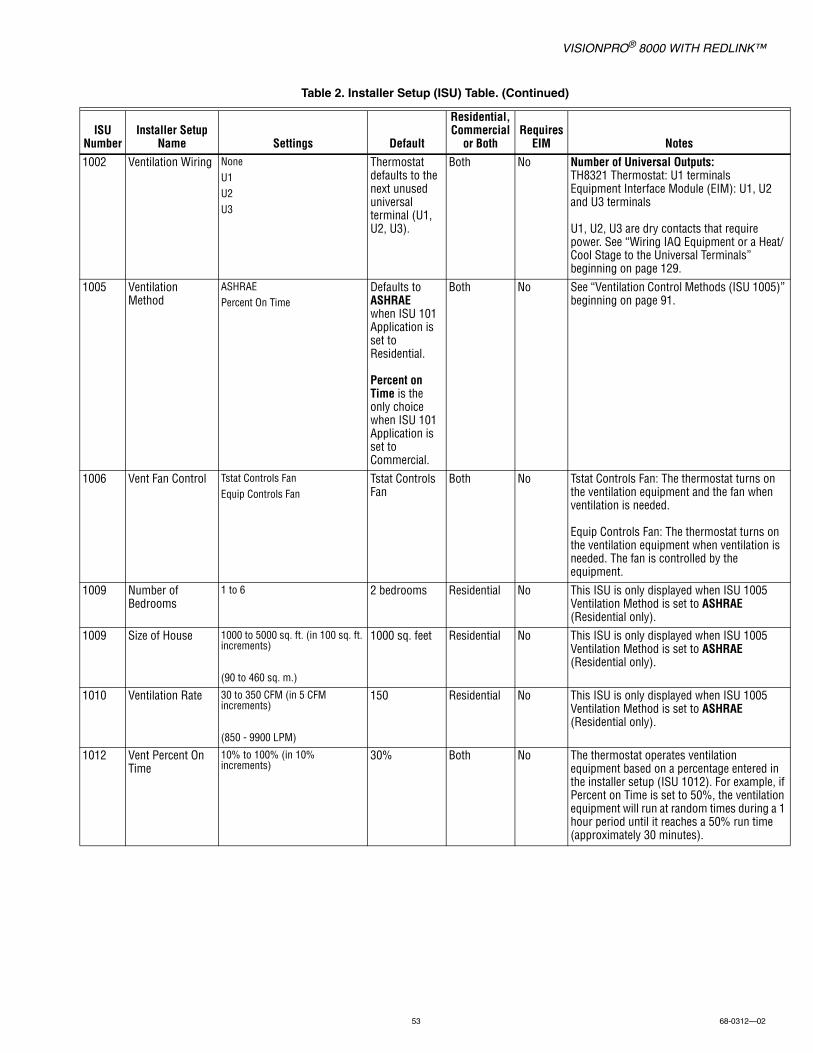
VISIONPRO® 8000 WITH REDLINK™
53 68-0312—02
1002 Ventilation Wiring NoneU1U2U3
Thermostat defaults to the next unused universal terminal (U1, U2, U3).
Both No Number of Universal Outputs:TH8321 Thermostat: U1 terminalsEquipment Interface Module (EIM): U1, U2 and U3 terminals
U1, U2, U3 are dry contacts that require power. See “Wiring IAQ Equipment or a Heat/Cool Stage to the Universal Terminals” beginning on page 129.
1005 Ventilation Method
ASHRAEPercent On Time
Defaults to ASHRAEwhen ISU 101 Application is set to Residential.
Percent on Time is the only choice when ISU 101 Application is set to Commercial.
Both No See “Ventilation Control Methods (ISU 1005)” beginning on page 91.
1006 Vent Fan Control Tstat Controls FanEquip Controls Fan
Tstat Controls Fan
Both No Tstat Controls Fan: The thermostat turns on the ventilation equipment and the fan when ventilation is needed.
Equip Controls Fan: The thermostat turns on the ventilation equipment when ventilation is needed. The fan is controlled by the equipment.
1009 Number of Bedrooms
1 to 6 2 bedrooms Residential No This ISU is only displayed when ISU 1005 Ventilation Method is set to ASHRAE (Residential only).
1009 Size of House 1000 to 5000 sq. ft. (in 100 sq. ft. increments)
(90 to 460 sq. m.)
1000 sq. feet Residential No This ISU is only displayed when ISU 1005 Ventilation Method is set to ASHRAE (Residential only).
1010 Ventilation Rate 30 to 350 CFM (in 5 CFM increments)
(850 - 9900 LPM)
150 Residential No This ISU is only displayed when ISU 1005 Ventilation Method is set to ASHRAE (Residential only).
1012 Vent Percent On Time
10% to 100% (in 10% increments)
30% Both No The thermostat operates ventilation equipment based on a percentage entered in the installer setup (ISU 1012). For example, if Percent on Time is set to 50%, the ventilation equipment will run at random times during a 1 hour period until it reaches a 50% run time (approximately 30 minutes).
Table 2. Installer Setup (ISU) Table. (Continued)
ISU Number
Installer Setup Name Settings Default
Residential, Commercial
or BothRequires
EIM Notes

VISIONPRO® 8000 WITH REDLINK™
68-0312—02 54
1012 Vent Priority LockoutsASHRAE
Lockouts Residential No Lockouts are Priority: The thermostat places a priority on lockouts versus the ASHRAE 62.2 ventilation standard. The thermostat will not run ventilation during the following lockout conditions (if configured) unless you manually call for ventilation:• Lockout Ventilation during Outdoor Conditions
(ISU 1013)• Lockout Ventilation on Humidification or
Dehumidification Calls (ISU 1014)• Lockout Ventilation during “Sleep” (Residential)
or “Unoccupied” (Commercial) program periods. Note: This option is set by the user on the Ventilation screen in the Menu.
ASHRAE is Priority: ASHRAE requires additional ventilation following a long off cycle. The thermostat meets the ASHRAE 62.2 ventilation standard by running additional ventilation when outdoor conditions are favorable. If ASHRAE cannot be met when outdoor conditions are favorable, the thermostat will override the outdoor lockouts and run ventilation. When using this option, it is recommended to increase the rate (CFM) of the ventilation equipment to meet the ASHRAE 62.2 ventilation standard in a shorter run time.
Notes:• ISU 1014 Lockout Ventilation on Humidification
or Dehumidification calls is not an option when you select ASHRAE is Priority.
• The ability to lockout ventilation during the “Sleep” or Unoccupied program periods is not an option when you select ASHRAE is Priority.
1013 Low Outdoor Temp Vent Lockout
Off -20° F to 40° F (in 5° F increments)
Off Both No Requires an outdoor sensor.
This ISU is only displayed when ISU 1000 Ventilation Type is set to ERV / HRV or Fresh Air Damper.
See “Ventilation — Outdoor Condition Lockouts (ISU 1013)” beginning on page 91.
1013 High Outdoor Temp Vent Lockout
Off80° F to 110° F (in 5° F increments)
Off Both No Requires an outdoor sensor.
This ISU is only displayed when ISU 1000 Ventilation Type is set to ERV / HRV or Fresh Air Damper.
See “Ventilation — Outdoor Condition Lockouts (ISU 1013)” beginning on page 91.
1013 High Out. Dew Point Vent Lockout
Off65° F to 85° F (in 5° F increments)
Off Both No Requires a Wireless Outdoor Sensor (sense outdoor humidity).
This ISU is only displayed when ISU 1000 Ventilation Type is set to ERV / HRV or Fresh Air Damper.
See “Ventilation — Outdoor Condition Lockouts (ISU 1013)” beginning on page 91.
Table 2. Installer Setup (ISU) Table. (Continued)
ISU Number
Installer Setup Name Settings Default
Residential, Commercial
or BothRequires
EIM Notes

VISIONPRO® 8000 WITH REDLINK™
55 68-0312—02
1014 Vent During Hum or Dehum Calls
YesNo
Yes Both No This feature is used to help reach the user's desired humidity level by not allowing the ventilation equipment to run during a call for humidification or dehumidification.
Yes: Ventilation is allowed to run during a call for humidification or dehumidification.
No: Ventilation is NOT allowed to run during a call for humidification or dehumidification.
1016 Vent On High Indoor Humidity
OffOn
On Both No This ISU is only displayed when ISU 1000 Ventilation Type is set to ERV / HRV.
Off: The humidity level has no effect on ventilation.
On: The thermostat removes excess humidity by turning on the ventilator when the indoor humidity rises 10% above the user's humidification setting. The thermostat must be in the heat mode to ventilate on high humidity.
1017 Ventilator Core Reminder
Off3, 6, 9, 12 Calendar Months
Off Both No Ventilator Core Cleaning Reminder
1017 Ventilator Filter Reminder
Off3, 6, 9, 12 Calendar Months
Off Both No Ventilator Filter Cleaning Reminder
1100 Number of UV Devices
0, 1, 2 0 Both No Press the up/down arrows to select the number of UV devices installed in the system. Some systems may have two UV devices, one for the A-Coil and another for Air Treatment. A replacement reminder can be setup for each one. Select 0 if no UV devices are installed.
1105 UV Bulb 1 Reminder
Note: “1” is not displayed if there is only 1 UV Bulb
Off, 6, 12, 24 Calendar Months Off Both No UV Bulb 1 Replacement Reminder
1105 UV Bulb 2 Reminder
Off, 6, 12, 24 Calendar Months Off Both No UV Bulb 2 Replacement Reminder
1200 Custom Reminders
View / Edit Custom RemindersAdd Custom Reminders
None Both No See “Customizable Reminders” beginning on page 96.
28 Backlighting On DemandContinuous
On Demand Both No Select Continuous or On Demand backlighting. Select Continuous backlighting if you would like the backlight to be on all the time (C wire is required for Continuous backlighting).
Select On Demand backlighting if you would like the backlight to only turn on after a key press. After you complete your changes, the screen stays lit for 16 seconds if the thermostat is battery powered only or it stays lit for 45 seconds if the thermostat is system powered (C wire).
1400 Clock Format 12 hour24 hour
12 Both No
1401 Daylight Saving Time
OffOn
On Both No Set to Off in areas that do not follow Daylight Saving Time.
Table 2. Installer Setup (ISU) Table. (Continued)
ISU Number
Installer Setup Name Settings Default
Residential, Commercial
or BothRequires
EIM Notes

VISIONPRO® 8000 WITH REDLINK™
68-0312—02 56
1402 Indoor Temperature Offset
-3° F to 3° F (in 1° F increments) 0° F Both No 0° F - No difference in displayed temperature and the actual room temperature.
The thermostat displays up to 3°F (1.5°C) lower or higher than the actual measured temperature.
1402 Indoor Humidity Offset
-12% to 12% (in 1% increments) 0% Both No 0% - No difference in displayed humidity and the actual room humidity.
The thermostat displays up to 12% lower or higher than the actual measured humidity.
1404 Alert Light Indicator
OnOff
On Both No The thermostat has a built in light indicator. When an alert is active, the light will be on continuous if the thermostat is powered with 24 VAC (C wire) or it will flash if the thermostat is powered with batteries only. The light also turns on when the system setting is set to Em Heat.
Select On to use the light indicator or select Off to turn off the light.
1500 Dealer Name [Dealer Name] None Both No Dealer information is displayed to the user when an alert is active and the user can access this information by selecting "Dealer Information" in the Menu.
1500 Dealer Phone [Dealer Phone] None Both No
1501 Dealer Email Address
[Dealer Email Address] None Both No
1501 Dealer Website [Dealer Website] None Both No
1502 Dealer Message [Dealer Message] None Both No
Table 2. Installer Setup (ISU) Table. (Continued)
ISU Number
Installer Setup Name Settings Default
Residential, Commercial
or BothRequires
EIM Notes
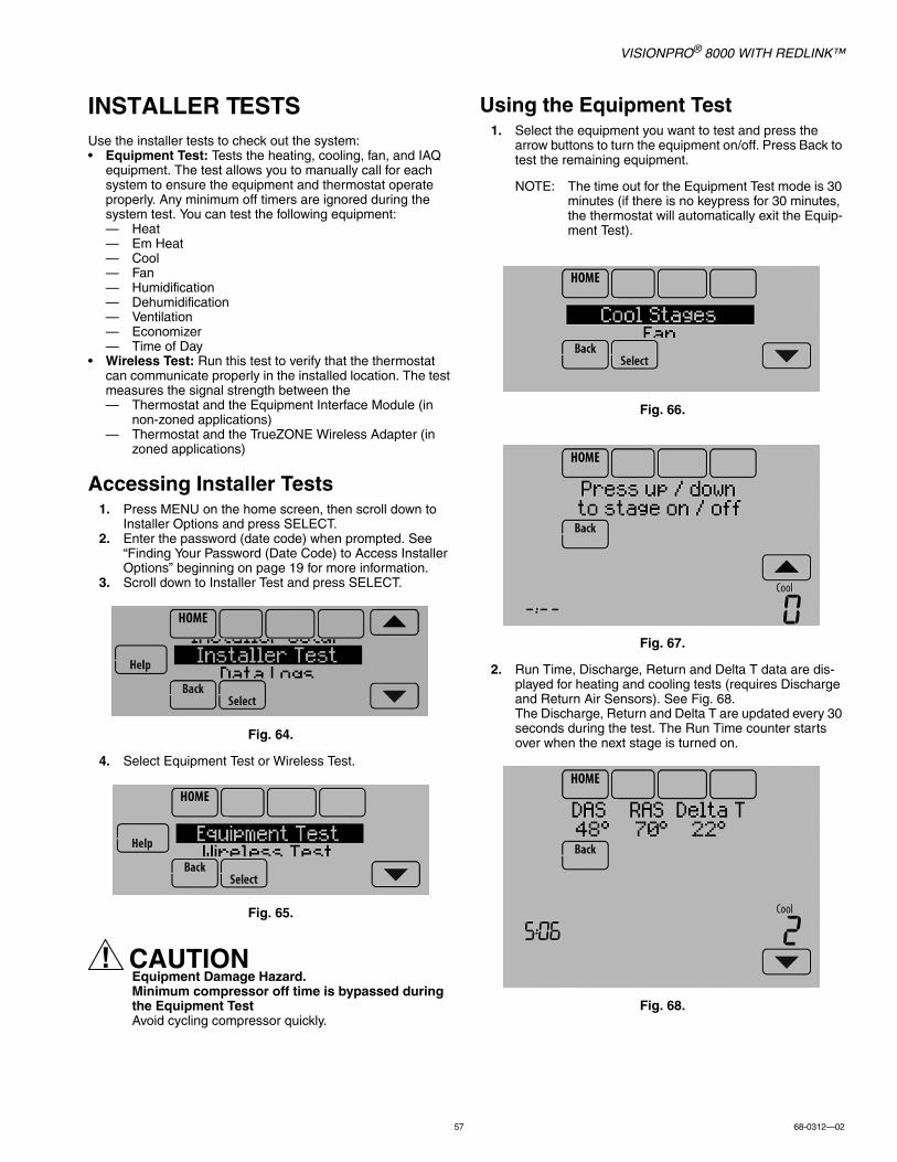
VISIONPRO® 8000 WITH REDLINK™
57 68-0312—02
INSTALLER TESTSUse the installer tests to check out the system:• Equipment Test: Tests the heating, cooling, fan, and IAQ
equipment. The test allows you to manually call for each system to ensure the equipment and thermostat operate properly. Any minimum off timers are ignored during the system test. You can test the following equipment:— Heat— Em Heat— Cool— Fan— Humidification— Dehumidification— Ventilation— Economizer— Time of Day
• Wireless Test: Run this test to verify that the thermostat can communicate properly in the installed location. The test measures the signal strength between the— Thermostat and the Equipment Interface Module (in
non-zoned applications)— Thermostat and the TrueZONE Wireless Adapter (in
zoned applications)
Accessing Installer Tests1. Press MENU on the home screen, then scroll down to
Installer Options and press SELECT.2. Enter the password (date code) when prompted. See
“Finding Your Password (Date Code) to Access Installer Options” beginning on page 19 for more information.
3. Scroll down to Installer Test and press SELECT.
Fig. 64.
4. Select Equipment Test or Wireless Test.
Fig. 65.
CAUTIONEquipment Damage Hazard.Minimum compressor off time is bypassed during the Equipment TestAvoid cycling compressor quickly.
Using the Equipment Test1. Select the equipment you want to test and press the
arrow buttons to turn the equipment on/off. Press Back to test the remaining equipment.
NOTE: The time out for the Equipment Test mode is 30 minutes (if there is no keypress for 30 minutes, the thermostat will automatically exit the Equip-ment Test).
Fig. 66.
Fig. 67.
2. Run Time, Discharge, Return and Delta T data are dis-played for heating and cooling tests (requires Discharge and Return Air Sensors). See Fig. 68. The Discharge, Return and Delta T are updated every 30 seconds during the test. The Run Time counter starts over when the next stage is turned on.
Fig. 68.
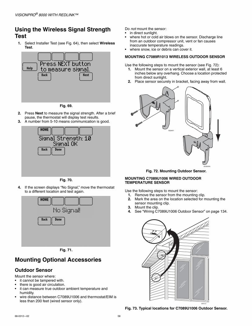
VISIONPRO® 8000 WITH REDLINK™
68-0312—02 58
Using the Wireless Signal Strength Test
1. Select Installer Test (see Fig. 64), then select Wireless Test.
Fig. 69.
2. Press Next to measure the signal strength. After a brief pause, the thermostat will display test results.
3. A number from 5-10 means communication is good.
Fig. 70.
4. If the screen displays “No Signal,” move the thermostat to a different location and test again.
Fig. 71.
Mounting Optional Accessories
Outdoor SensorMount the sensor where:• it cannot be tampered with.• there is good air circulation.• it can measure true outdoor ambient temperature and
humidity.• wire distance between C7089U1006 and thermostat/EIM is
less than 200 feet (wired sensor only).
Do not mount the sensor:• in direct sunlight.• where hot or cold air blows on the sensor. Discharge line
from an outdoor compressor unit, vent or fan causes inaccurate temperature readings.
• where snow, ice or debris can cover it.
MOUNTING C7089R1013 WIRELESS OUTDOOR SENSOR
Use the following steps to mount the sensor (see Fig. 72):1. Mount the sensor on a vertical exterior wall, at least 6
inches below any overhang. Choose a location protected from direct sunlight.
2. Place sensor securely in bracket, facing away from wall.
Fig. 72. Mounting Outdoor Sensor.
MOUNTING C7089U1006 WIRED OUTDOOR TEMPERATURE SENSOR
Use the following steps to mount the sensor:1. Remove the sensor from the mounting clip.2. Mark the area on the location selected for mounting the
sensor mounting clip.3. Mount the clip.4. See “Wiring C7089U1006 Outdoor Sensor” on page 134.
Fig. 73. Typical locations for C7089U1006 Outdoor Sensor.
M28491
M28849A
M7514
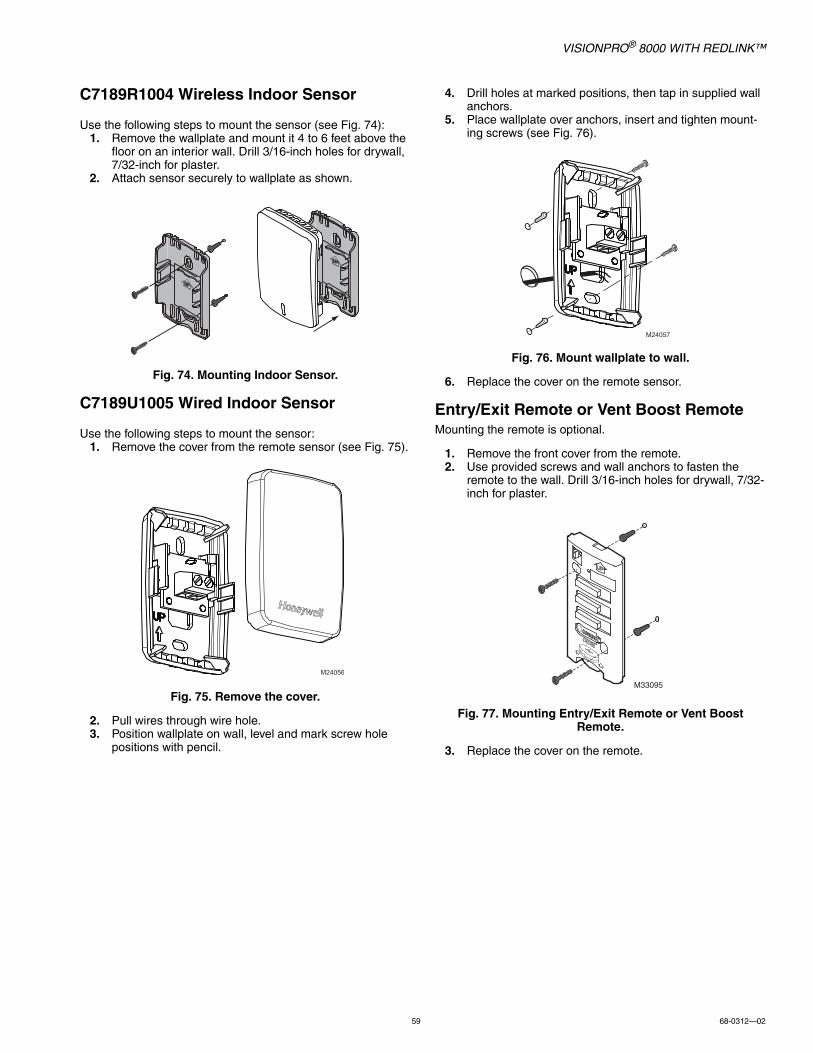
VISIONPRO® 8000 WITH REDLINK™
59 68-0312—02
C7189R1004 Wireless Indoor Sensor
Use the following steps to mount the sensor (see Fig. 74):1. Remove the wallplate and mount it 4 to 6 feet above the
floor on an interior wall. Drill 3/16-inch holes for drywall, 7/32-inch for plaster.
2. Attach sensor securely to wallplate as shown.
Fig. 74. Mounting Indoor Sensor.
C7189U1005 Wired Indoor Sensor
Use the following steps to mount the sensor:1. Remove the cover from the remote sensor (see Fig. 75).
Fig. 75. Remove the cover.
2. Pull wires through wire hole.3. Position wallplate on wall, level and mark screw hole
positions with pencil.
4. Drill holes at marked positions, then tap in supplied wall anchors.
5. Place wallplate over anchors, insert and tighten mount-ing screws (see Fig. 76).
Fig. 76. Mount wallplate to wall.
6. Replace the cover on the remote sensor.
Entry/Exit Remote or Vent Boost RemoteMounting the remote is optional.
1. Remove the front cover from the remote.2. Use provided screws and wall anchors to fasten the
remote to the wall. Drill 3/16-inch holes for drywall, 7/32-inch for plaster.
Fig. 77. Mounting Entry/Exit Remote or Vent Boost Remote.
3. Replace the cover on the remote.
M24056
M24057
M33095
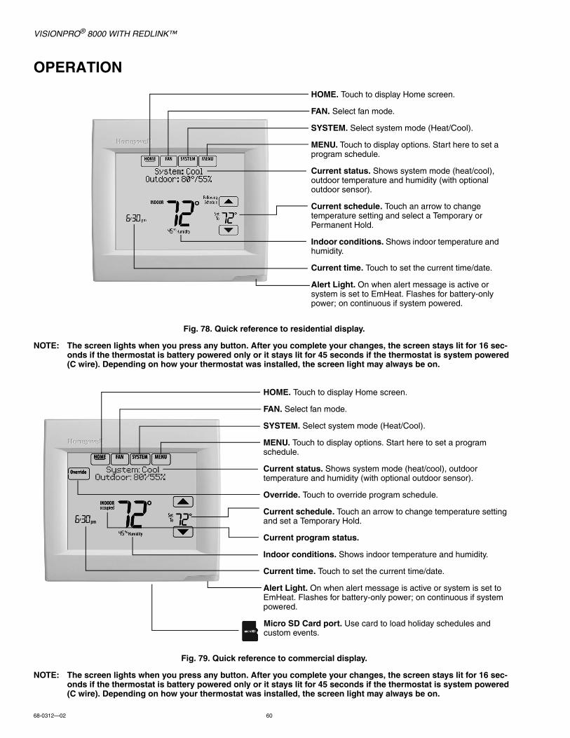
VISIONPRO® 8000 WITH REDLINK™
68-0312—02 60
OPERATION
Fig. 78. Quick reference to residential display.
NOTE: The screen lights when you press any button. After you complete your changes, the screen stays lit for 16 sec-onds if the thermostat is battery powered only or it stays lit for 45 seconds if the thermostat is system powered (C wire). Depending on how your thermostat was installed, the screen light may always be on.
Fig. 79. Quick reference to commercial display.
NOTE: The screen lights when you press any button. After you complete your changes, the screen stays lit for 16 sec-onds if the thermostat is battery powered only or it stays lit for 45 seconds if the thermostat is system powered (C wire). Depending on how your thermostat was installed, the screen light may always be on.
HOME. Touch to display Home screen.
FAN. Select fan mode.
SYSTEM. Select system mode (Heat/Cool).
MENU. Touch to display options. Start here to set a program schedule.
Current status. Shows system mode (heat/cool), outdoor temperature and humidity (with optional outdoor sensor).
Current schedule. Touch an arrow to change temperature setting and select a Temporary or Permanent Hold.
Indoor conditions. Shows indoor temperature and humidity.
Current time. Touch to set the current time/date.
Alert Light. On when alert message is active or system is set to EmHeat. Flashes for battery-only power; on continuous if system powered.
HOME. Touch to display Home screen.
FAN. Select fan mode.
SYSTEM. Select system mode (Heat/Cool).
MENU. Touch to display options. Start here to set a program schedule.
Current status. Shows system mode (heat/cool), outdoor temperature and humidity (with optional outdoor sensor).
Override. Touch to override program schedule.
Current schedule. Touch an arrow to change temperature setting and set a Temporary Hold.
Current program status.
Indoor conditions. Shows indoor temperature and humidity.
Current time. Touch to set the current time/date.
Alert Light. On when alert message is active or system is set to EmHeat. Flashes for battery-only power; on continuous if system powered.
Micro SD Card port. Use card to load holiday schedules and custom events.

VISIONPRO® 8000 WITH REDLINK™
61 68-0312—02
Setting the Time/Date1. Touch the current time. The screen displays Select Option.
Fig. 80.
2. Touch Time or Date, then touch Select.
Fig. 81.
3. Touch or until the proper time/date is displayed.4. Touch Done to save or Cancel to ignore changes.
Fig. 82.
5. Touch Home to redisplay the Home screen.
NOTE: The date is not shown on the home screen; how-ever, it should be set to allow the thermostat to adjust time automatically for daylight saving time and for other features such as vacation hold.
Setting the Fan1. Touch FAN to display fan settings.
Fig. 83.
2. Touch On, Auto, Circ, or Follow Schedule.3. Touch Done to save and exit.
• On: Fan is always on.• Auto: Fan runs only when heating or cooling system is
on.• Circ: Fan runs randomly, about 35% of the time
(residential only).• Follow Schedule: Fan controlled by program.
Fig. 84.
NOTE: In commercial use, touch Auto or On to temporar-ily override the programmed fan schedule.
Setting System Mode1. Touch SYSTEM to display system settings.
Fig. 85.
2. Touch desired option• Heat: Controls only the heating system.• Cool: Controls only the cooling system.• Off: Heating/cooling systems are off.• Auto: Selects heating or cooling depending on the
indoor temperature.• Em Heat (heat pumps with aux. heat): Controls
auxiliary/emergency heat. Compressor is locked out.
Fig. 86.
3. Touch Done to save and exit.
NOTE: The Auto and Em Heat system settings may not appear, depending on how your thermostat was installed.
MCR34092
MCR34155
Select Option Time Date
MCR34094
Please Set Time6 :30 PM
MCR34096
MCR34097
On Auto Circ
MCR34098
MCR34099
Heat Cool AutoOff

VISIONPRO® 8000 WITH REDLINK™
68-0312—02 62
Preset Energy-Saving SchedulesThese default Energy Saver settings can reduce expenses by as much as 33%.
* Period 2 is cancelled by default. If you activate it, the values shown above are default settings.
Adjusting Program Schedules1. Touch MENU.
Fig. 87.
2. Select Edit Schedule to display Use Scheduling Assis-tant?
Fig. 88.
• Touch Yes to create a schedule by answering simple questions.
• Touch No to manually create a program schedule.
Fig. 89.
NOTE: To reduce costs, use the “Preset Energy-Saving Schedules” on page 62.
3. Select the days to schedule, touch Next.
Fig. 90.
4. Touch or to set your Wake time for selected day(s).5. Touch or to set Heat and Cool temperatures for the
Wake period.6. Touch other time periods (Leave, Return, Sleep) to set
time and temperatures for each.7. Touch Done to save and exit (Touch Cancel to exit with-
out saving changes).
Fig. 91.
NOTE: Touch Cancel Period to eliminate any unwanted time period.
Touch Fan Setting to customize fan settings for any time period.
Table 3. Residential Use Default Schedule.
PeriodStart Time
Heat (Mon-Fri)
Cool (Mon-Fri)
Heat (Sat-Sun)
Cool (Sat-Sun)
Wake 6:00 am 70° 78° 70° 78°
Leave 8:00 am 62° 85° 62° 85°
Return 6:00 pm 70° 78° 70° 78°
Sleep 10:00 pm 62° 82° 62° 82°
Table 4. Commercial Use Default Schedule.
Period Start Time Heat Cool Fan
Occupied 1 8:00 am 70° 75° On
Unoccupied 1 10:00 pm 55° 85° Auto
Occupied 2* 12:00 am 70° 75° On
Unoccupied 2* 12:00 am 55° 85° Auto
MCR34100
MCR34101
Edit ScheduleView Schedule
MCR34102
Use SchedulingAssistant?
MCR34151
Select the daysto schedule
MCR34152
Set Waketime & temperature

VISIONPRO® 8000 WITH REDLINK™
63 68-0312—02
Overriding Schedules: Residential Use
1. Touch or to adjust the temperature (right side of screen) and the Hold Until time (left side). The schedule will resume when the Hold Until time expires.
Fig. 92.
2. Select Permanent Hold to keep the same temperature until you change it or resume the program schedule.
Touch Cancel Hold at any time to resume the program schedule.
Overriding Schedules: Commercial UseTouch or to adjust the temperature. It will be maintained until the hold time you set.• To change the hold time, touch the Hold Until arrow buttons.
This time can be adjusted up to the maximum time set by the installer.
Fig. 93.
• Touch Override to use a pre-set occupied temperature if a person uses the room during an unoccupied period. The new temperature will be maintained for 1 hour and can be adjusted up to the maximum time set by the installer.
Fig. 94.
The programmed schedule will resume when the override timer expires. Touch Cancel Hold at any time to resume the program schedule.
Viewing Equipment Status1. Touch MENU.
Fig. 95.
2. Select Equipment Status.
Fig. 96.
3. Touch or to view the status of all the equipment your thermostat is controlling. Depending on how your thermostat was installed, the Equipment Status screen can report data about the following systems:
• Heating and cooling• Fan• Humidification• Dehumidification• Ventilation• Maintenance reminders• Thermostat information
Fig. 97.
MCR34103
Temporary HoldPermanent Hold
MCR34169
MCR34106
MCR34100
MCR34108
Equipment StatusDate/Time
MCR34109
Heat Stage 1: OffCool Stage 1: On

VISIONPRO® 8000 WITH REDLINK™
68-0312—02 64
Setting Vacation Hold: Residential UseThis feature helps you save energy while you are away, and restores comfortable settings just before you return home.
1. Touch MENU.
Fig. 98.
2. Select Vacation Mode.
Fig. 99.
3. Touch or to select the date you leave, then touch Next for further scheduling details, including times of day, temperature settings, return date, and return settings.
Fig. 100.
4. Review your selections on the last display, and touch Done to save your settings. Touch Cancel to ignore the changes.
Fig. 101.
Setting Holiday/Event Schedules: Commercial UseThis feature helps you conserve energy when the workplace is unoccupied for special events and holidays.
1. Touch MENU.
Fig. 102.
2. Select Holiday Schedule.
Fig. 103.
3. Select the item you want to schedule and touch Next for further scheduling details.• Custom Events lets you set up other days for special
schedules.• US and Canadian Holiday options let you select from
a list of holidays commonly observed in each country.
Fig. 104.
4. Make selections as prompted on each screen. For more information, see next two pages.
5. Touch Done to save your settings.
Setting Custom Events: Commercial UseThis feature lets you customize temperature settings to be maintained during a specific event. You can set up an event for a specific date or day in a month. The thermostat resumes normal scheduling after the event. The thermostat can be scheduled for up to 25 Custom Events.
1. Select Custom Events from the Holiday Schedule menu.
Fig. 105.
MCR34100
MCR34110
Vacation ModeEquipment Status
MCR34111
Date You LeaveJul 17, 2012
MCR34112
Jul 25 - Jul 26Heat: 72 Cool: 78
MCR34100
MCR34113
Holiday ScheduleHoliday Mode
MCR34114
Custom EventsUS Holidays
MCR34114
Custom EventsUS Holidays

VISIONPRO® 8000 WITH REDLINK™
65 68-0312—02
2. Select Create New Event.
Fig. 106.
3. Select Specific Date or Month/Weekday.• For Specific Date, you are prompted to select the
event’s start date, settings, end date, and frequency.• For Month/Weekday, you are prompted to select the
month, day of the week, week of the month, settings, length of event, and frequency for the event.
Fig. 107.
4. Review the settings and touch Done to save them. Touch Cancel to ignore the changes.
Fig. 108.
Setting Holiday Schedule: Commercial UseThis feature lets you customize temperature settings to be maintained on specified national holidays. The thermostat resumes normal scheduling between selected holidays.
1. Select US Holidays or Canadian Holidays from the Holi-day Schedule menu.
2. Select Add/Edit Holidays. A list of national holidays is displayed.
Fig. 109.
3. Touch the check box next to each holiday for which you want to maintain specific settings, (Touch or to scroll through the holiday list.) then touch Next.
Set the holiday schedule for Occupied or Unoccupied temperatures, depending whether the building will be in use.
Fig. 110.
4. Touch or to select the Heat and Cool temperatures.
Fig. 111.
5. Review the settings and touch Done to save them. Touch Cancel to ignore changes.
Setting Holiday Override: Commercial UseThis feature lets you customize temperature settings to be maintained from now until a specified date. The thermostat resumes normal scheduling on the date you select.
MCR34116
Create New Event
MCR34117
Select OccurenceSpecific Date
MCR34118
Schedule adjustedto 62 in heating
MCR34119
Add / Edit Holidays
MCR34120
Select US holidays New Year’s Day
MCR34121
TemperatureDuring Holiday
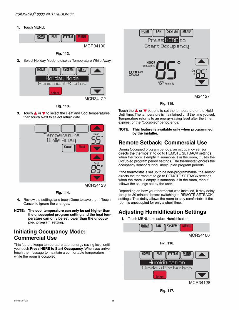
VISIONPRO® 8000 WITH REDLINK™
68-0312—02 66
1. Touch MENU.
Fig. 112.
2. Select Holiday Mode to display Temperature While Away.
Fig. 113.
3. Touch or to select the Heat and Cool temperatures, then touch Next to select return date.
Fig. 114.
4. Review the settings and touch Done to save them. Touch Cancel to ignore the changes.
NOTE: The cool temperature can only be set higher than the unoccupied program setting and the heat tem-perature can only be set lower than the unoccu-pied program setting.
Initiating Occupancy Mode: Commercial UseThis feature keeps temperature at an energy saving level until you touch Press HERE to Start Occupancy. When you arrive, touch the message to maintain a comfortable temperature while the room is occupied.
Fig. 115.
Touch the or buttons to set the temperature or the Hold Until time. The temperature is maintained until the time you set. Temperature returns to an energy-saving level after the timer expires, or the “Occupied” period ends.
NOTE: This feature is available only when programmed by the installer.
Remote Setback: Commercial UseDuring Occupied program periods, an occupancy sensor directs the thermostat to go to REMOTE SETBACK settings when the room is empty. If someone is in the room, it uses the Occupied program period settings. The thermostat ignores the occupancy sensor during Unoccupied program periods.
If the thermostat is set up to be non-programmable, the sensor directs the thermostat to go to REMOTE SETBACK settings when the room is empty. If someone is in the room, then it follows the settings set by the user.
Depending on how your thermostat was installed, it may delay for up to 30 minutes before switching to REMOTE SETBACK settings. This delay allows the room to stay comfortable if the room is unoccupied for only a short time.
Adjusting Humidification Settings1. Touch MENU and select Humidification.
Fig. 116.
Fig. 117.
MCR34100
MCR34122
Holiday ModeEquipment Status
MCR34123
TemperatureWhile Away
M34127
Press HERE toStart Occupancy
MCR34100
MCR34128
HumidificationWindow Protection
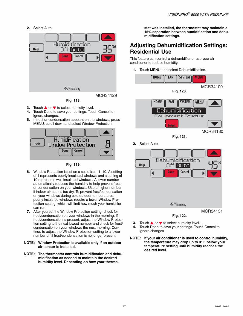
VISIONPRO® 8000 WITH REDLINK™
67 68-0312—02
2. Select Auto.
Fig. 118.
3. Touch or to select humidity level.4. Touch Done to save your settings. Touch Cancel to
ignore changes.5. If frost or condensation appears on the windows, press
MENU, scroll down and select Window Protection.
Fig. 119.
6. Window Protection is set on a scale from 1–10. A setting of 1 represents poorly insulated windows and a setting of 10 represents well insulated windows. A lower number automatically reduces the humidity to help prevent frost or condensation on your windows. Use a higher number if indoor air seems too dry. To prevent frost/condensation on your windows during cold outdoor temperatures, poorly insulated windows require a lower Window Pro-tection setting, which will limit how much your humidifier can run.
7. After you set the Window Protection setting, check for frost/condensation on your windows in the morning. If frost/condensation is present, adjust the Window Protec-tion setting to the next lowest number and check for frost/condensation on your windows the next morning. Con-tinue to adjust the Window Protection setting to a lower number until frost/condensation is no longer present.
NOTE: Window Protection is available only if an outdoor air sensor is installed.
NOTE: The thermostat controls humidification and dehu-midification as needed to maintain the desired humidity level. Depending on how your thermo-
stat was installed, the thermostat may maintain a 15% separation between humidification and dehu-midification settings.
Adjusting Dehumidification Settings: Residential UseThis feature can control a dehumidifier or use your air conditioner to reduce humidity.
1. Touch MENU and select Dehumidification.
Fig. 120.
Fig. 121.
2. Select Auto.
Fig. 122.
3. Touch or to select humidity level.4. Touch Done to save your settings. Touch Cancel to
ignore changes.
NOTE: If your air conditioner is used to control humidity, the temperature may drop up to 3° F below your temperature setting until humidity reaches the desired level.
MCR34129
HumidificationOff Auto
MCR34100
MCR34130
DehumidificationEquipment Status
MCR34131
DehumidificationOff Auto

VISIONPRO® 8000 WITH REDLINK™
68-0312—02 68
Adjusting Dehumidification Settings: Commercial UseThis feature can control a dehumidifier or use your air conditioner to reduce humidity.
1. Touch MENU and select Dehumidification.
Fig. 123.
Fig. 124.
2. Select Auto.
Fig. 125.
3. Touch or to select humidity level.4. Touch Done to save your settings. Touch Cancel to
ignore changes.
If your air conditioner is used to control humidity, the thermostat may use the following methods to maintain humidity:• Cool from 1° to 5° F lower than your temperature setting.• Run cooling for the minimum “on” time to reduce humidity.• Run cooling and heating at the same time to reduce
humidity without lowering the temperature.
Adjusting Ventilation Settings1. Touch MENU, and select Ventilation.
Fig. 126.
Fig. 127.
2. Select Mode, Temporary Boost, or Lockout, then select appropriate options.
Fig. 128.
3. Touch Done to save your settings. Touch Cancel to ignore changes.
Fig. 129.
Ventilation OptionsMode:
Auto: Ventilation runs as programmed by the installer.
Off: Ventilation remains off unless turned on using the timer.
On: Ventilation is always on.
Fig. 130.
MCR34100
MCR34130
DehumidificationEquipment Status
MCR34131
DehumidificationOff Auto
MCR34100
MCR34132
VentilationEquipment Status
MCR34133
ModeTemporary Boost
MCR34134
MCR34135
Ventilation ModeOff Auto On
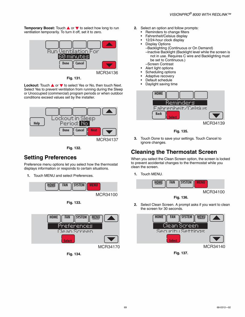
VISIONPRO® 8000 WITH REDLINK™
69 68-0312—02
Temporary Boost: Touch or to select how long to run ventilation temporarily. To turn it off, set it to zero.
Fig. 131.
Lockout: Touch or to select Yes or No, then touch Next. Select Yes to prevent ventilation from running during the Sleep or Unoccupied (commercial) program periods or when outdoor conditions exceed values set by the installer.
Fig. 132.
Setting PreferencesPreference menu options let you select how the thermostat displays information or responds to certain situations.
1. Touch MENU and select Preferences.
Fig. 133.
Fig. 134.
2. Select an option and follow prompts:• Reminders to change filters• Fahrenheit/Celsius display• 12/24-hour clock display• Display Options
–Backlighting (Continuous or On Demand)–Inactive Backlight (Backlight level while the screen is
not in use. Requires C wire and Backlighting must be set to Continuous.)
–Screen Contrast• Alert light options• Scheduling options• Adaptive recovery• Default schedule• Daylight saving time
Fig. 135.
3. Touch Done to save your settings. Touch Cancel to ignore changes.
Cleaning the Thermostat ScreenWhen you select the Clean Screen option, the screen is locked to prevent accidental changes to the thermostat while you clean the screen.
1. Touch MENU.
Fig. 136.
2. Select Clean Screen. A prompt asks if you want to clean the screen for 30 seconds.
Fig. 137.
MCR34136
Run Ventilation For 60 minutes
MCR34137
Lockout in Sleep Period: No
MCR34100
MCR34170
PreferencesClean Screen
MCR34139
RemindersFahrenheit/Celsius
MCR34100
MCR34140
Clean ScreenSecurity Settings

VISIONPRO® 8000 WITH REDLINK™
68-0312—02 70
3. Touch Yes. A countdown timer displays elapsed time until the screen is reactivated.
Fig. 138.
NOTE: Do NOT spray any liquid directly on the thermo-stat. Spray liquids onto cloth, then use the damp cloth to clean the screen. Use water or household glass cleaner. Avoid abrasive cleansers.
Adjusting Security SettingsYou can adjust security options to prevent unauthorized changes to system settings.
1. Touch MENU and select Security Settings.
Fig. 139.
Fig. 140.
2. Select an option and follow prompts:
Fig. 141.
• Unlocked: Full access allowed.• Partially locked: Only temperature can be changed.• Fully locked: No access allowed.
Fig. 142.
NOTE: If you choose to use a password for additional security, write it down for reference.
Viewing Dealer InformationCheck dealer information if you need to contact your installer for maintenance, repairs, or upgrades.
1. Touch MENU.
Fig. 143.
2. Select Dealer Information.
Fig. 144.
3. Scroll through the displayed information.4. Touch Done to return to the menu.
Fig. 145.
MCR34141
Clean screenfor 30 seconds?
MCR34100
MCR34142
Security SettingsDealer Information
MCR34143
Change Lock ModeCreate Password
M34197
Lock ModeUnlocked
MCR34100
MCR34022
Dealer InformationInstaller Options
MCR34162
ABC HEATING & AIR555-555-5555
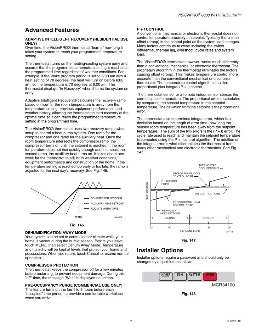
VISIONPRO® 8000 WITH REDLINK™
71 68-0312—02
Advanced FeaturesADAPTIVE INTELLIGENT RECOVERY (RESIDENTIAL USE ONLY)Over time, the VisionPRO® thermostat "learns" how long it takes your system to reach your programmed temperature setting.
The thermostat turns on the heating/cooling system early and assures that the programmed temperature setting is reached at the programmed time regardless of weather conditions. For example, if the Wake program period is set to 6:00 am with a heat setting of 70 degrees, the heat will turn on before 6:00 am, so the temperature is 70 degrees at 6:00 am. The thermostat displays "In Recovery" when it turns the system on early.
Adaptive Intelligent Recovery® calculates the recovery ramp based on how far the room temperature is away from the temperature setting, previous equipment performance and weather history, allowing the thermostat to start recovery at the optimal time so it can reach the programmed temperature setting at the programmed time.
The VisionPRO® thermostat uses two recovery ramps when setup to control a heat pump system. One ramp for the compressor and one ramp for the auxiliary heat. Once the room temperature intersects the compressor ramp, the compressor turns on until the setpoint is reached. If the room temperature does not rise quickly enough and intersects the second ramp, the auxiliary heat turns on. It takes about one week for the thermostat to adjust to weather conditions, equipment performance and construction of the home. If the temperature setting is reached too early or too late, the ramp is adjusted for the next day's recovery. See Fig. 146.
Fig. 146.
DEHUMIDIFICATION AWAY MODEYour system can be set to control indoor climate while your home is vacant during the humid season. Before you leave, touch MENU, then select Dehum Away Mode. Temperature and humidity will be kept at levels that protect your home and possessions. When you return, touch Cancel to resume normal operation.
COMPRESSOR PROTECTIONThe thermostat keeps the compressor off for a few minutes before restarting, to prevent equipment damage. During this "off" time, the message "Wait" is displayed on screen.
PRE-OCCUPANCY PURGE (COMMERCIAL USE ONLY)This feature turns on the fan 1 to 3 hours before each “occupied” time period, to provide a comfortable workplace when you arrive.
P + I CONTROLA conventional mechanical or electronic thermostat does not control temperature precisely at setpoint. Typically there is an offset (droop) in the control point as the system load changes. Many factors contribute to offset including the switch differential, thermal lag, overshoot, cycle rates and system load.
The VisionPRO® thermostat however, works much differently than a conventional mechanical or electronic thermostat. The proprietary algorithm in the thermostat eliminates the factors causing offset (droop). This makes temperature control more accurate than the conventional mechanical or electronic thermostat. The temperature control algorithm is called proportional plus integral (P + I) control.
The thermostat sensor or a remote indoor sensor senses the current space temperature. The proportional error is calculated by comparing the sensed temperature to the setpoint temperature. The deviation from the setpoint is the proportional error.
The thermostat also determines integral error, which is a deviation based on the length of error time (how long the sensed room temperature has been away from the setpoint temperature). The sum of the two errors is the (P + I) error. The cycle rate used to reach and maintain the setpoint temperature is computed using the P + I control algorithm. The addition of the integral error is what differentiates the thermostat from many other mechanical and electronic thermostats. See Fig. 147.
Fig. 147.
Installer OptionsInstaller options require a password and should only be changed by a qualified technician.
Fig. 148.
WAKE
COMPRESSOR SETPOINT
AUXILIARY HEAT SETPOINT
ROOM TEMPERATURE
M6406AHEATING COOLING
PERCENT LOAD
TE
MP
ER
AT
UR
E
THERMOSTAT
HEAT SETPOINT
P+I CONTROL
POINT
PROPORTIONAL COOL
CONTROL POINT
THERMOSTAT
COOL SETPOINT
P+I CONTROL POINT
PROPORTIONAL HEAT
CONTROL POINT
M4414
100 50 0 50 100
MCR34100

VISIONPRO® 8000 WITH REDLINK™
68-0312—02 72
Fig. 149.
Fig. 150.
Using the Temperature DisplayIn some circumstances, the temperature displayed on the Home screen may not match the temperature near the thermostat.
If your system is set up to use remote indoor sensors, it may be reading a sensor in another location.
Fig. 151.
Using the Humidity DisplayIn some circumstances, the humidity displayed on the Home screen may not match humidity near the thermostat.
Some systems are set up to use two sensors, one to control humidification, the other for dehumidification. These sensors are often installed in different locations.
Depending on how your thermostat was installed, the thermostat Home screen will display humidity readings from only one sensor.
Fig. 152.
Universal Outputs (U1, U2, U3)U1, U2, U3 are universal outputs that can be setup to control IAQ equipment and a stage of heating or cooling in the Installer Setup. Setup options are listed below. See Thermostat Wiring Guides on page 129 and Equipment Interface Module wiring guides on page 130.
Universal Output OptionsWith Equipment Interface Module (U1, U2, U3):• Humidification (ISU 803)• Dehumidification (ISU 904)• Ventilation (ISU 1002)• Cool Stage 3 (ISU 208)• Cool Stage 4 (ISU 209)• Geothermal Radiant Heat (ISU 203, 204)
TH8321 Thermostat Only (U1)• Humidification (ISU 803)• Dehumidification (ISU 904)• Ventilation (ISU 1002)• Cool Stage 3 (ISU 208)• Conventional Heat Stage 3 (ISU 210, 214)• Backup Heat Stage 2 for Heat Pumps (ISU 217)• Geothermal Radiant Heat (ISU 203)
Universal Inputs (S1, S2, S3, S4)S1, S2, S3 and S4 are universal inputs that can be setup to work with a sensor or dry contact device in the Installer Setup. Setup options and compatible sensors are listed below. See wiring diagrams on page 74 and page 135. The thermostat has 1 Universal Input and the Equipment Interface Module has 4 Universal Inputs.
MCR33976
Installer Options
MCR33977
Enter password0 0 0 0
MCR33985
Temperature reading depends on location of sensor
MCR3416Humidity reading depends on location of sensor.

VISIONPRO® 8000 WITH REDLINK™
73 68-0312—02
Universal Input OptionsIndoor Air Sensor (ISU 500)• C7189U1005 (10K)• C7772A1004 (20K)• C7772A1012 (20K)• TR21 (20K)• TR21-A (10K)
Outdoor Air Sensor (ISU 500)• C7089U1006 (10K)
Discharge/Return Air Sensors (ISU 500)• C7735A1000 (10k)• C7770A1006 (20K)• C7041 (20K)
Occupancy Sensor for Remote Setback (ISU 600) (Requires Equipment Interface Module)• WSK-24
Dry Contact Alerts (ISU 600) (Requires Equipment Interface Module)• Low Voltage Dry Contact Device
Data LogsThe Data Logs collect system information that can help point a service technician in the right direction when troubleshooting.
To access a Data Log, it must be saved to a MicroSD card. See “Using the Data Logs” beginning on page 73 and “MicroSD card” beginning on page 100 for more information.
Data Logs include the Alerts Log and the User Interactions Log.
Alerts LogThe Alerts Log stores a history of the most recent 25 alerts and records the date and time of each alert. It can be turned on, off, and reset at the thermostat.
Fig. 153.
The Alerts Log contains information about the alert and system information.
The Alerts Log can include:• The alert name and description.• System details at the time of the alert.• The alert status (snoozed, dismissed, recovered).
User Interactions LogThe User Interactions Log can help a service technician save time by determining if the issue is related to a system problem or an accidental user error.
The User Interactions Log records the date and time for most changes made by the user, whether made at the thermostat or from a remote location (smart phone, tablet, web, or Portable Comfort Control, etc.). The log saves the most recent 250 user changes, including:• Indoor Air Quality Settings• Maintenance Reminders• Temperature Settings• System/Fan Mode• Alerts (snoozed or dismissed)• Installer Setup• Date/Time
The User Interactions Log can be turned on, off, and reset at the thermostat.
Fig. 154.
Using the Data LogsTo view a data log, you must download the log to a microSD card and then view it on your computer. For more information on using the MicroSD card, see “MicroSD card” beginning on page 100.
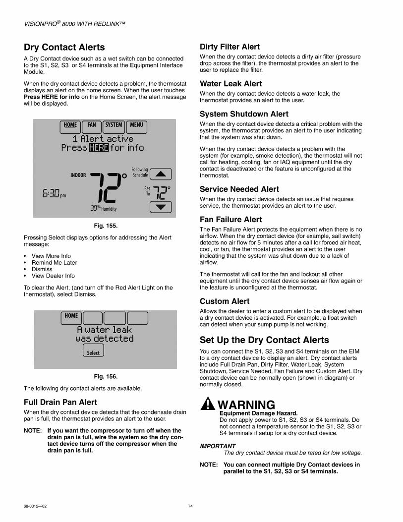
VISIONPRO® 8000 WITH REDLINK™
68-0312—02 74
Dry Contact AlertsA Dry Contact device such as a wet switch can be connected to the S1, S2, S3 or S4 terminals at the Equipment Interface Module.
When the dry contact device detects a problem, the thermostat displays an alert on the home screen. When the user touches Press HERE for info on the Home Screen, the alert message will be displayed.
Fig. 155.
Pressing Select displays options for addressing the Alert message:
• View More Info• Remind Me Later• Dismiss• View Dealer Info
To clear the Alert, (and turn off the Red Alert Light on the thermostat), select Dismiss.
Fig. 156.
The following dry contact alerts are available.
Full Drain Pan AlertWhen the dry contact device detects that the condensate drain pan is full, the thermostat provides an alert to the user.
NOTE: If you want the compressor to turn off when the drain pan is full, wire the system so the dry con-tact device turns off the compressor when the drain pan is full.
Dirty Filter AlertWhen the dry contact device detects a dirty air filter (pressure drop across the filter), the thermostat provides an alert to the user to replace the filter.
Water Leak AlertWhen the dry contact device detects a water leak, the thermostat provides an alert to the user.
System Shutdown AlertWhen the dry contact device detects a critical problem with the system, the thermostat provides an alert to the user indicating that the system was shut down.
When the dry contact device detects a problem with the system (for example, smoke detection), the thermostat will not call for heating, cooling, fan or IAQ equipment until the dry contact is deactivated or the feature is unconfigured at the thermostat.
Service Needed AlertWhen the dry contact device detects an issue that requires service, the thermostat provides an alert to the user.
Fan Failure AlertThe Fan Failure Alert protects the equipment when there is no airflow. When the dry contact device (for example, sail switch) detects no air flow for 5 minutes after a call for forced air heat, cool, or fan, the thermostat provides an alert to the user indicating that the system was shut down due to a lack of airflow.
The thermostat will call for the fan and lockout all other equipment until the dry contact device senses air flow again or the feature is unconfigured at the thermostat.
Custom AlertAllows the dealer to enter a custom alert to be displayed when a dry contact device is activated. For example, a float switch can detect when your sump pump is not working.
Set Up the Dry Contact AlertsYou can connect the S1, S2, S3 and S4 terminals on the EIM to a dry contact device to display an alert. Dry contact alerts include Full Drain Pan, Dirty Filter, Water Leak, System Shutdown, Service Needed, Fan Failure and Custom Alert. Dry contact device can be normally open (shown in diagram) or normally closed.
WARNINGEquipment Damage Hazard.Do not apply power to S1, S2, S3 or S4 terminals. Do not connect a temperature sensor to the S1, S2, S3 or S4 terminals if setup for a dry contact device.
IMPORTANTThe dry contact device must be rated for low voltage.
NOTE: You can connect multiple Dry Contact devices in parallel to the S1, S2, S3 or S4 terminals.
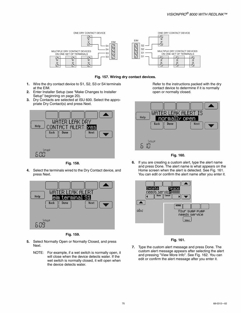
VISIONPRO® 8000 WITH REDLINK™
75 68-0312—02
Fig. 157. Wiring dry contact devices.
1. Wire the dry contact device to S1, S2, S3 or S4 terminals at the EIM.
2. Enter Installer Setup (see “Make Changes to Installer Setup” beginning on page 20).
3. Dry Contacts are selected at ISU 600. Select the appro-priate Dry Contact(s) and press Next.
Fig. 158.
4. Select the terminals wired to the Dry Contact device, and press Next.
Fig. 159.
5. Select Normally Open or Normally Closed, and press Next.
NOTE: For example, if a wet switch is normally open, it will close when the device detects water. If the wet switch is normally closed, it will open when the device detects water.
Refer to the instructions packed with the dry contact device to determine if it is normally open or normally closed.
Fig. 160.
6. If you are creating a custom alert, type the alert name and press Done. The alert name is what appears on the Home screen when the alert is detected. See Fig. 161. You can edit or confirm the alert name after you enter it.
Fig. 161.
7. Type the custom alert message and press Done. The custom alert message appears after selecting the alert and pressing "View More Info". See Fig. 162. You can edit or confirm the alert message after you enter it.
MULTIPLE DRY CONTACT DEVICES ON ONE SET OF TERMINALS
EIM
ONE DRY CONTACT DEVICE
MULTIPLE DRY CONTACT DEVICES ON ONE SET OF TERMINALS
EIM
ONE DRY CONTACT DEVICE
S4
S4
S3
S3
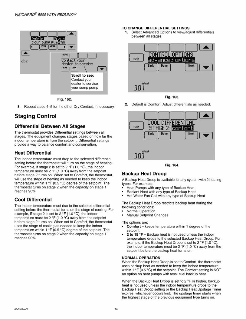
VISIONPRO® 8000 WITH REDLINK™
68-0312—02 76
Fig. 162.
8. Repeat steps 4–5 for the other Dry Contact, if necessary.
Staging Control
Differential Between All StagesThe thermostat provides Differential settings between all stages. The equipment changes stages based on how far the indoor temperature is from the setpoint. Differential settings provide a way to balance comfort and conservation.
Heat DifferentialThe indoor temperature must drop to the selected differential setting before the thermostat will turn on the stage of heating. For example, if stage 2 is set to 2 °F (1.0 °C), the indoor temperature must be 2 °F (1.0 °C) away from the setpoint before stage 2 turns on. When set to Comfort, the thermostat will use the stage of heating as needed to keep the indoor temperature within 1 °F (0.5 °C) degree of the setpoint. The thermostat turns on stage 2 when the capacity on stage 1 reaches 90%.
Cool DifferentialThe indoor temperature must rise to the selected differential setting before the thermostat turns on the stage of cooling. For example, if stage 2 is set to 2 °F (1.0 °C), the indoor temperature must be 2 °F (1.0 °C) away from the setpoint before stage 2 turns on. When set to Comfort, the thermostat uses the stage of cooling as needed to keep the indoor temperature within 1 °F (0.5 °C) degree of the setpoint. The thermostat turns on stage 2 when the capacity on stage 1 reaches 90%.
TO CHANGE DIFFERENTIAL SETTINGS1. Select Advanced Options to view/adjust differentials
between all stages.
Fig. 163.
2. Default is Comfort. Adjust differentials as needed.
Fig. 164.
Backup Heat DroopA Backup Heat Droop is available for any system with 2 heating types. For example:• Heat Pumps with any type of Backup Heat• Radiant Heat with any type of Backup Heat• Hot Water Fan Coil with any type of Backup Heat
The Backup Heat Droop restricts backup heat during the following conditions:• Normal Operation• Manual Setpoint Changes
The options are:• Comfort – keeps temperature within 1 degree of the
setpoint.• 2 to 15 °F – Backup heat is not used unless the indoor
temperature drops to the selected Backup Heat Droop. For example, if the Backup Heat Droop is set to 2 °F (1.0 °C), the indoor temperature must be 2 °F (1.0 °C) away from the setpoint before the backup heat turns on.
NORMAL OPERATIONWhen the Backup Heat Droop is set to Comfort, the thermostat uses backup heat as needed to keep the indoor temperature within 1 °F (0.5 °C) of the setpoint. The Comfort setting is NOT an option on heat pumps with fossil fuel backup heat.
When the Backup Heat Droop is set to 2 °F or higher, backup heat is not used unless the indoor temperature drops to the Backup Heat Droop setting or the Backup Heat Upstage Timer expires, whichever occurs first. The upstage timer starts when the highest stage of the previous equipment type turns on.
Scroll to see:Contact your dealer to service your sump pump
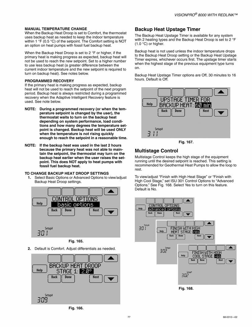
VISIONPRO® 8000 WITH REDLINK™
77 68-0312—02
MANUAL TEMPERATURE CHANGEWhen the Backup Heat Droop is set to Comfort, the thermostat uses backup heat as needed to keep the indoor temperature within 1 °F (0.5 °C) of the setpoint. The Comfort setting is NOT an option on heat pumps with fossil fuel backup heat.
When the Backup Heat Droop is set to 2 °F or higher, if the primary heat is making progress as expected, backup heat will not be used to reach the new setpoint. Set to a higher number to use less backup heat (a greater difference between the current indoor temperature and the new setpoint is required to turn on backup heat). See notes below.
PROGRAMMED RECOVERYIf the primary heat is making progress as expected, backup heat will not be used to reach the setpoint of the next program period. Backup heat is always restricted during a programmed recovery when the Adaptive Intelligent Recovery feature is used. See note below.
NOTE: During a programmed recovery (or when the tem-perature setpoint is changed by the user), the thermostat waits to turn on the backup heat depending on system performance, load condi-tions and how many degrees the temperature set-point is changed. Backup heat will be used ONLY when the temperature is not rising quickly enough to reach the setpoint in a reasonable time.
NOTE: If the backup heat was used in the last 2 hours because the primary heat was not able to main-tain the setpoint, the thermostat may turn on the backup heat earlier when the user raises the set-point. This does NOT apply to heat pumps with fossil fuel backup heat.
TO CHANGE BACKUP HEAT DROOP SETTINGS1. Select Basic Options or Advanced Options to view/adjust
Backup Heat Droop settings.
Fig. 165.
2. Default is Comfort. Adjust differentials as needed.
Fig. 166.
Backup Heat Upstage TimerThe Backup Heat Upstage Timer is available for any system with 2 heating types and the Backup Heat Droop is set to 2 °F (1.0 °C) or higher.
Backup heat is not used unless the indoor temperature drops to the Backup Heat Droop setting or the Backup Heat Upstage Timer expires, whichever occurs first. The upstage timer starts when the highest stage of the previous equipment type turns on.
Backup Heat Upstage Timer options are Off, 30 minutes to 16 hours. Default is Off.
Fig. 167.
Multistage ControlMultistage Control keeps the high stage of the equipment running until the desired setpoint is reached. This setting is recommended for Geothermal Heat Pumps to allow the loop to rest.
To view/adjust “Finish with High Heat Stage” or “Finish with High Cool Stage,” set ISU 301 Control Options to “Advanced Options.” See Fig. 168. Select Yes to turn on this feature. Default is No.
Fig. 168.
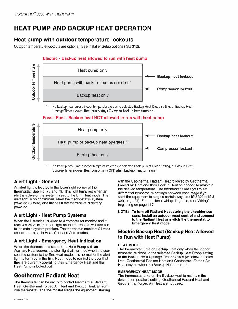
VISIONPRO® 8000 WITH REDLINK™
68-0312—02 78
HEAT PUMP AND BACKUP HEAT OPERATION
Heat pump with outdoor temperature lockoutsOutdoor temperature lockouts are optional. See Installer Setup options (ISU 312).
Alert Light - GeneralAn alert light is located in the lower right corner of the thermostat. See Fig. 78 and 79. This light turns red when an alert is active or the system is set to the Em. Heat mode. The alert light is on continuous when the thermostat is system powered (C Wire) and flashes if the thermostat is battery powered.
Alert Light - Heat Pump SystemsWhen the L terminal is wired to a compressor monitor and it receives 24 volts, the alert light on the thermostat will turn red to indicate a system problem. The thermostat monitors 24 volts on the L terminal in Heat, Cool and Auto modes.
Alert Light - Emergency Heat IndicationWhen the thermostat is setup for a Heat Pump with an Auxiliary Heat source, the alert light will turn red when the user sets the system to the Em. Heat mode. It is normal for the alert light to turn red in the Em. Heat mode to remind the user that they are currently operating their Emergency Heat and the Heat Pump is locked out.
Geothermal Radiant HeatThe thermostat can be setup to control Geothermal Radiant Heat, Geothermal Forced Air Heat and Backup Heat, all from one thermostat. The thermostat stages the equipment starting
with the Geothermal Radiant Heat followed by Geothermal Forced Air Heat and then Backup Heat as needed to maintain the desired temperature. The thermostat allows you to set differential temperature settings between each stage if you want the equipment to stage a certain way (see ISU 303 to ISU 309, page 27). For additional wiring diagrams, see “Wiring” beginning on page 117.
NOTE: To turn off Radiant Heat during the shoulder sea-sons, install an outdoor reset control and connect to the Radiant Heat or switch the thermostat to Emergency Heat mode.
Electric Backup Heat (Backup Heat Allowed to Run with Heat Pump)
HEAT MODEThe thermostat turns on Backup Heat only when the indoor temperature drops to the selected Backup Heat Droop setting or the Backup Heat Upstage Timer expires (whichever occurs first). Geothermal Radiant Heat and Geothermal Forced Air Heat stay on when the Backup Heat turns on.
EMERGENCY HEAT MODEThe thermostat turns on the Backup Heat to maintain the desired temperature setting. Geothermal Radiant Heat and Geothermal Forced Air Heat are not used.
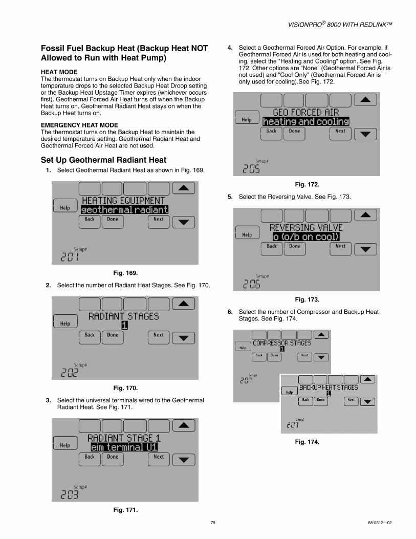
VISIONPRO® 8000 WITH REDLINK™
79 68-0312—02
Fossil Fuel Backup Heat (Backup Heat NOT Allowed to Run with Heat Pump)
HEAT MODEThe thermostat turns on Backup Heat only when the indoor temperature drops to the selected Backup Heat Droop setting or the Backup Heat Upstage Timer expires (whichever occurs first). Geothermal Forced Air Heat turns off when the Backup Heat turns on. Geothermal Radiant Heat stays on when the Backup Heat turns on.
EMERGENCY HEAT MODEThe thermostat turns on the Backup Heat to maintain the desired temperature setting. Geothermal Radiant Heat and Geothermal Forced Air Heat are not used.
Set Up Geothermal Radiant Heat1. Select Geothermal Radiant Heat as shown in Fig. 169.
Fig. 169.
2. Select the number of Radiant Heat Stages. See Fig. 170.
Fig. 170.
3. Select the universal terminals wired to the Geothermal Radiant Heat. See Fig. 171.
Fig. 171.
4. Select a Geothermal Forced Air Option. For example, if Geothermal Forced Air is used for both heating and cool-ing, select the "Heating and Cooling" option. See Fig. 172. Other options are "None" (Geothermal Forced Air is not used) and "Cool Only" (Geothermal Forced Air is only used for cooling).See Fig. 172.
Fig. 172.
5. Select the Reversing Valve. See Fig. 173.
Fig. 173.
6. Select the number of Compressor and Backup Heat Stages. See Fig. 174.
Fig. 174.

VISIONPRO® 8000 WITH REDLINK™
68-0312—02 80
7. Select the Backup Heat Type. See Fig. 175.
Fig. 175.
INDOOR AIR QUALITY (IAQ) CONTROL
HumidificationThe thermostat reads the indoor humidity level and allows the user to set a humidification setting with or without window protection.
The thermostat can be set up to control a humidifier in any system mode in the Installer Setup (ISU 806). A discharge air sensor is required to humidify in the cool mode.
If humidification and dehumidification are setup to operate in the same system mode (Heat, Cool, Off) and you are sensing humidity from one location, the thermostat will automatically enforce a 15% deadband between the humidification and dehumidification settings. The thermostat will automatically switch between humidification and dehumidification to maintain the desired humidity level.
If humidification and dehumidification are setup to operate in the same system mode (Heat, Cool, Off) and you are sensing humidity from two different locations using a remote wireless indoor sensor, the thermostat will allow humidification and dehumidification to operate at the same time, and there is no deadband between humidification and dehumidification settings.
Window ProtectionWindow Protection limits the amount of humidity to prevent frost or condensation on windows. Window Protection (ISU 805) requires an outdoor sensor.
The thermostat prevents frost or condensation on windows by not allowing the humidifier to run above a certain level. To prevent frost or condensation, the thermostat may turn off the humidifier before the humidity setting is reached.
To adjust the Window Protection setting, press MENU, scroll down and select Window Protection. Window Protection is set on a scale from 1-10. A setting of "1" represents poorly insulated windows and a setting of "10" represents well insulated windows. A lower number automatically reduces the
humidity to help prevent frost or condensation on your windows. Use a higher number if indoor air seems too dry. To prevent frost/condensation on your windows during cold outdoor temperatures, poorly insulated windows require a lower Window Protection setting, which will limit how much your humidifier can run.
After you set the Window Protection setting, check for frost/condensation on your windows in the morning. If frost/condensation is present, adjust the Window Protection setting to the next lowest number and check for frost/condensation on your windows the next morning. Continue to adjust the Window Protection setting to a lower number until frost/condensation is no longer present.
Fig. 176.
If Window Protection is turned Off, the thermostat controls the humidity level to the user's desired humidity setting. Frost or condensation may appear on windows.
Set up Humidification1. Select the Humidifier Type at ISU 800. See Fig. 177.
NOTE: Based on the humidifier type you select, the thermostat defaults to the most commonly used settings for that humidifier type.For example, a Bypass or Fan Powered humidi-fier will default ISU 807 to “Hum when Heat is On.”A Steam humidifier will default ISU 807 to "Tstat Controls Fan."
Fig. 177.
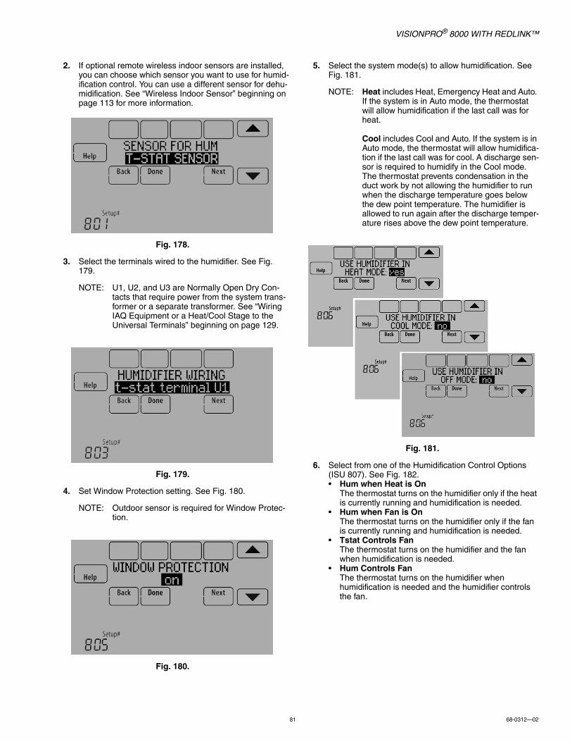
VISIONPRO® 8000 WITH REDLINK™
81 68-0312—02
2. If optional remote wireless indoor sensors are installed, you can choose which sensor you want to use for humid-ification control. You can use a different sensor for dehu-midification. See “Wireless Indoor Sensor” beginning on page 113 for more information.
Fig. 178.
3. Select the terminals wired to the humidifier. See Fig. 179.
NOTE: U1, U2, and U3 are Normally Open Dry Con-tacts that require power from the system trans-former or a separate transformer. See “Wiring IAQ Equipment or a Heat/Cool Stage to the Universal Terminals” beginning on page 129.
Fig. 179.
4. Set Window Protection setting. See Fig. 180.
NOTE: Outdoor sensor is required for Window Protec-tion.
Fig. 180.
5. Select the system mode(s) to allow humidification. See Fig. 181.
NOTE: Heat includes Heat, Emergency Heat and Auto. If the system is in Auto mode, the thermostat will allow humidification if the last call was for heat.
Cool includes Cool and Auto. If the system is in Auto mode, the thermostat will allow humidifica-tion if the last call was for cool. A discharge sen-sor is required to humidify in the Cool mode. The thermostat prevents condensation in the duct work by not allowing the humidifier to run when the discharge temperature goes below the dew point temperature. The humidifier is allowed to run again after the discharge temper-ature rises above the dew point temperature.
Fig. 181.
6. Select from one of the Humidification Control Options (ISU 807). See Fig. 182.• Hum when Heat is On
The thermostat turns on the humidifier only if the heat is currently running and humidification is needed.
• Hum when Fan is OnThe thermostat turns on the humidifier only if the fan is currently running and humidification is needed.
• Tstat Controls FanThe thermostat turns on the humidifier and the fan when humidification is needed.
• Hum Controls FanThe thermostat turns on the humidifier when humidification is needed and the humidifier controls the fan.
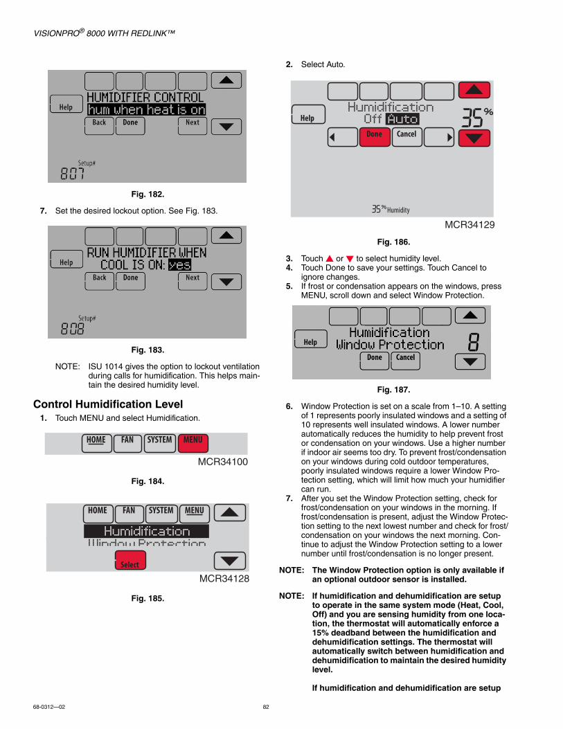
VISIONPRO® 8000 WITH REDLINK™
68-0312—02 82
Fig. 182.
7. Set the desired lockout option. See Fig. 183.
Fig. 183.
NOTE: ISU 1014 gives the option to lockout ventilation during calls for humidification. This helps main-tain the desired humidity level.
Control Humidification Level1. Touch MENU and select Humidification.
Fig. 184.
Fig. 185.
2. Select Auto.
Fig. 186.
3. Touch or to select humidity level.4. Touch Done to save your settings. Touch Cancel to
ignore changes.5. If frost or condensation appears on the windows, press
MENU, scroll down and select Window Protection.
Fig. 187.
6. Window Protection is set on a scale from 1–10. A setting of 1 represents poorly insulated windows and a setting of 10 represents well insulated windows. A lower number automatically reduces the humidity to help prevent frost or condensation on your windows. Use a higher number if indoor air seems too dry. To prevent frost/condensation on your windows during cold outdoor temperatures, poorly insulated windows require a lower Window Pro-tection setting, which will limit how much your humidifier can run.
7. After you set the Window Protection setting, check for frost/condensation on your windows in the morning. If frost/condensation is present, adjust the Window Protec-tion setting to the next lowest number and check for frost/condensation on your windows the next morning. Con-tinue to adjust the Window Protection setting to a lower number until frost/condensation is no longer present.
NOTE: The Window Protection option is only available if an optional outdoor sensor is installed.
NOTE: If humidification and dehumidification are setup to operate in the same system mode (Heat, Cool, Off) and you are sensing humidity from one loca-tion, the thermostat will automatically enforce a 15% deadband between the humidification and dehumidification settings. The thermostat will automatically switch between humidification and dehumidification to maintain the desired humidity level.
If humidification and dehumidification are setup
MCR34100
MCR34128
HumidificationWindow Protection
MCR34129
HumidificationOff Auto

VISIONPRO® 8000 WITH REDLINK™
83 68-0312—02
to operate in the same system mode (Heat, Cool, Off) and you are sensing humidity from two differ-ent locations using a remote wireless indoor sen-sor, the thermostat will allow humidification and dehumidification to operate at the same time, and there is no deadband between humidification and dehumidification settings.
Dehumidification - ResidentialThe thermostat reads the indoor humidity level and allows the user to set a dehumidification setting. The thermostat controls the humidity level using the cooling system or a whole house dehumidifier.
If humidification and dehumidification are setup to operate in the same system mode (Heat, Cool, Off) and you are sensing humidity from one location, the thermostat will automatically enforce a 15% deadband between the humidification and dehumidification settings. The thermostat will automatically switch between humidification and dehumidification to maintain the desired humidity level.
If humidification and dehumidification are setup to operate in the same system mode (Heat, Cool, Off) and you are sensing humidity from two different locations using a remote wireless indoor sensor (for example, main level and crawl space), the thermostat will allow humidification and dehumidification to operate at the same time, and there is no deadband between humidification and dehumidification settings.
Dehumidification using the Cooling SystemWhen set for A/C with Low Speed Fan or A/C with High Speed Fan, an overcooling limit can be set from 0 °F to 3 °F (ISU 907). The thermostat uses the cooling system to reduce humidity by lowering the temperature up to 3° F below the current cool setpoint until the desired humidity level is reached.
If set for A/C with Low Speed Fan, configure U1, U2, or U3 as normally open or normally closed (ISU 905) and wire to the Low Speed Fan terminal on the equipment. For example, if the U1, U2, or U3 terminal is normally closed, it will open when the thermostat calls for dehumidification.See “Wiring IAQ Equipment or a Heat/Cool Stage to the Universal Terminals” beginning on page 129.
NOTE: The thermostat will not lower the fan speed when the second stage of cooling is on.
Set up Dehumidification With Cooling SystemSome screens shown in this section may not appear on the thermostat, depending on how you set up dehumidification.
1. Select the Dehumidification Equipment in ISU 900. See Fig. 188.
Fig. 188.
2. If optional remote wireless indoor sensors are installed, you can choose which sensor you want to use for dehu-midification control. For example, you can use one sen-sor for humidification control, and another for dehumidification. See “Wireless Indoor Sensor” begin-ning on page 113 for more information.
Fig. 189.
3. If you are sensing humidity from two separate locations (one for humidification and another for dehumidification), you can select which humidity reading to display on the home screen. See “Wireless Indoor Sensor” beginning on page 113 for more information.
Fig. 190.

VISIONPRO® 8000 WITH REDLINK™
68-0312—02 84
4. Select the terminals wired to the A/C with Low Speed Fan. See Fig. 191.
Fig. 191.
5. Select whether the U1, U2, or U3 terminals are Normally Open or Normally Closed. See Fig. 192.• Normally Open – contacts are normally open and will
close during a call for dehumidification• Normally Closed – contacts are normally closed and
will open during a call for dehumidification.
Fig. 192.
6. Set the Overcooling Limit. See Fig. 193. Options:• 0 °F to 3 °F (A/C with Low Speed Fan)• 1 °F to 3 °F (A/C with High Speed Fan)
Fig. 193.
NOTE: ISU 1014 gives the option to lockout ventilation on calls for dehumidification. This helps main-tain the desired humidity level.
Dehumidification using a Whole House DehumidifierThe Whole House Dehumidifier option requires a dedicated unit for dehumidification. The thermostat can be set to control dehumidification in all modes (Heat, Off, Cool [ISU 912]).
Set up Dehumidification With Whole House DehumidifierSome screens shown in this section may not appear on the thermostat, depending on how you set up dehumidification.
1. Select the Dehumidification Equipment in ISU 900. See Fig. 194.
Fig. 194.
2. If optional remote wireless indoor sensors are installed, you can choose which sensor you want to use for dehu-midification control. For example, you can use one sen-sor for humidification control, and another for dehumidification. See “Wireless Indoor Sensor” begin-ning on page 113 for more information.
Fig. 195.
3. If you are sensing humidity from two separate locations (one for humidification and another for dehumidification), you can select which humidity reading to display on the home screen. See “Wireless Indoor Sensor” beginning on page 113 for more information.
Fig. 196.
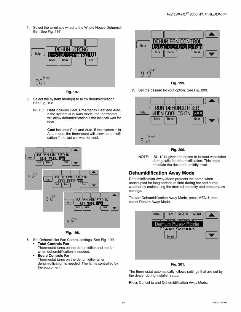
VISIONPRO® 8000 WITH REDLINK™
85 68-0312—02
4. Select the terminals wired to the Whole House Dehumid-ifier. See Fig. 197.
Fig. 197.
5. Select the system mode(s) to allow dehumidification. See Fig. 198.
NOTE: Heat includes Heat, Emergency Heat and Auto. If the system is in Auto mode, the thermostat will allow dehumidification if the last call was for heat.
Cool includes Cool and Auto. If the system is in Auto mode, the thermostat will allow dehumidifi-cation if the last call was for cool.
Fig. 198.
6. Set Dehumidifier Fan Control settings. See Fig. 199.• Tstat Controls Fan
Thermostat turns on the dehumidifier and the fan when dehumidification is needed.
• Equip Controls FanThermostat turns on the dehumidifier when dehumidification is needed. The fan is controlled by the equipment.
Fig. 199.
7. Set the desired lockout option. See Fig. 200.
Fig. 200.
NOTE: ISU 1014 gives the option to lockout ventilation during calls for dehumidification. This helps maintain the desired humidity level.
Dehumidification Away ModeDehumidification Away Mode protects the home when unoccupied for long periods of time during hot and humid weather by maintaining the desired humidity and temperature settings.
To start Dehumidification Away Mode, press MENU, then select Dehum Away Mode.
Fig. 201.
The thermostat automatically follows settings that are set by the dealer during installer setup.
Press Cancel to end Dehumidification Away Mode.

VISIONPRO® 8000 WITH REDLINK™
68-0312—02 86
Fig. 202.
Set up Dehumidification Away Mode1. Select Allowed at ISU 918. See Fig. 203.
Fig. 203.
2. Set Fan Control settings. See Fig. 204.• On: Fan is always on.• Automatic: Fan runs only when cooling system is on.• Circulate: Fan runs randomly, about 35% of the time.
Fig. 204.
3. Set temperature and dehumidification settings. See Fig. 205.
• Low Limit Temperature SettingIf the cooling system is used to control humidity while Dehumidification Away Mode is active, the thermostat allows the cooling system to lower the indoor air to the Low Limit Temperature Setting to reach the Dehumidification Setting at ISU 920.
• Temperature SettingThe temperature maintained while Dehumidification Away Mode is active and the desired humidity level is satisfied.
• Dehumidification SettingThe desired humidity level while Dehumidification Away Mode is active.
Fig. 205.

VISIONPRO® 8000 WITH REDLINK™
87 68-0312—02
Control Dehumidification Level1. Touch MENU and select Dehumidification.
Fig. 206.
Fig. 207.
2. Select Auto.
Fig. 208.
3. Touch or to select humidity level.4. Touch Done to save your settings. Touch Cancel to
ignore changes.
NOTE: If your air conditioner is used to control humidity, the temperature may drop up to 3° F below your temperature setting until humidity reaches the desired level.
NOTE: If humidification and dehumidification are setup to operate in the same system mode (Heat, Cool, Off) and you are sensing humidity from one loca-tion, the thermostat will automatically enforce a 15% deadband between the humidification and dehumidification settings. The thermostat will automatically switch between humidification and dehumidification to maintain the desired humidity level.
If humidification and dehumidification are setup to operate in the same system mode (Heat, Cool, Off) and you are sensing humidity from two differ-ent locations using a remote wireless indoor sen-sor (for example, main level and crawl space), the thermostat will allow humidification and dehumid-ification to operate at the same time, and there is no deadband between humidification and dehu-midification settings.
Dehumidification - CommercialThe thermostat reads the indoor humidity level and allows the user to set a dehumidification setting. The thermostat controls the humidity level using the cooling system or a dehumidifier.
If humidification and dehumidification are setup to operate in the same system mode (Heat, Cool, Off) and you are sensing humidity from one location, the thermostat will automatically enforce a 15% deadband between the humidification and dehumidification settings. The thermostat will automatically switch between humidification and dehumidification to maintain the desired humidity level.
If humidification and dehumidification are setup to operate in the same system mode (Heat, Cool, Off) and you are sensing humidity from two different locations using a remote wireless indoor sensor (for example, main level and crawl space), the thermostat will allow humidification and dehumidification to operate at the same time, and there is no deadband between humidification and dehumidification settings.
Dehumidification Equipment Options: (ISU 900)• A/C with Low Fan• A/C with High Fan• Hot Gas Bypass• Dehumidifier
NOTE: Hot Gas Bypass - During a call for dehumidifica-tion, the cooling capacity will be used to remove more latent heat than sensible heat. The operation of Hot Gas Bypass varies by equipment. For more details, contact the equipment manufacturer.
Dehumidification using the Cooling SystemDehumidification using A/C with Low Speed Fan, A/C with High Speed Fan or Hot Gas Bypass, has the following methods of dehumidification control (ISU 908):
Fig. 209.
Basic (ISU 908): This option uses the cooling system to reach the desired humidity level. Minimum On Time, Cooling Droop and Reheat are not used with this method. This setting is commonly used if your dehumidification equipment is Hot Gas Bypass.
Minimum On Time (ISU 908 and 909): This option ensures that the compressor runs long enough to effectively reduce humidity when the cooling equipment is cycled on. The compressor will run for the minimum “on time” you set until the desired humidity level is reached.
MCR34100
MCR34130
DehumidificationEquipment Status
MCR34131
DehumidificationOff Auto

VISIONPRO® 8000 WITH REDLINK™
68-0312—02 88
Cooling Droop (ISU 908 and 910): This option uses the cooling system to lower the temperature up to 5° F below the current cool setpoint until the desired humidity is reached. The Dehum Over Cooling Limit range is from 1° to 5° F.
Cooling Droop with Minimum On Time (ISU 908, 909, and 910): This method uses both options above to reduce humidity while maintaining a comfortable temperature.
Reheat (ISU 908): This option allows heating to run during dehumidification to help maintain a comfortable temperature. If only cooling stage 1 is used, during the “off” cycle, both cooling and heating run at the same time as needed to dehumidify without overcooling. This option cannot be used in the Heat mode. This option is effective only if using a system with the A-Coil located before the heating coil (heat exchanger). This feature requires a conventional forced air heating system (gas, oil, or electric) in the application.
NOTE: Reheat can be used on heat pump applications that have a forced air backup heat source (gas, oil, or electric). The thermostat will turn on the first stage of forced air backup heat during Reheat.
NOTE: Reheat can be used on systems where the A-Coil is located after the heating coil (heat exchanger), but it is not effective at removing humidity.
Reheat with Minimum On Time (ISU 908 and 909): This method uses both Reheat and Minimum On Time options above to reach the desired humidity level.
If set for A/C with Low Speed Fan, configure U1, U2, or U3 as normally open or normally closed (ISU 905) and wire to the Low Speed Fan terminal on the equipment. For example, if the U1, U2, or U3 terminal is normally closed, it will open when the thermostat calls for dehumidification.See “Wiring IAQ Equipment or a Heat/Cool Stage to the Universal Terminals” beginning on page 129.
NOTE: The thermostat will not lower the fan speed when the second stage of cooling is on.
Set up Dehumidification With Cooling SystemSome screens shown in this section may not appear on the thermostat, depending on how you set up dehumidification.
1. Select the Dehumidification Equipment in ISU 900. See Fig. 210.
Fig. 210.
2. If optional remote wireless indoor sensors are installed, you can choose which sensor you want to use for dehu-midification control. For example, you can use one sen-sor for humidification control, and another for dehumidification. See “Wireless Indoor Sensor” begin-ning on page 113 for more information.
Fig. 211.
3. If you are sensing humidity from two separate locations (one for humidification and another for dehumidification), you can select which humidity reading to display on the home screen. See “Wireless Indoor Sensor” beginning on page 113 for more information.
Fig. 212.
4. Select the terminals wired to the A/C with Low Speed Fan or Hot Gas Bypass. See Fig. 213.
Fig. 213.
5. Select whether the U1, U2, or U3 terminals are Normally Open or Normally Closed. See Fig. 214.• Normally Open – contacts are normally open and will
close during a call for dehumidification• Normally Closed – contacts are normally closed and
will open during a call for dehumidification.

VISIONPRO® 8000 WITH REDLINK™
89 68-0312—02
Fig. 214.
6. Set the Dehumidification Control. See Fig. 215. For more information about these options, see “Dehumidification using the Cooling System” on page 87.
Fig. 215.
NOTE: ISU 1014 gives the option to lockout ventilation on calls for dehumidification. This helps main-tain the desired humidity level.
Dehumidification using a DehumidifierThe Dehumidifier option requires a dedicated unit for dehumidification. The thermostat can be set to control dehumidification in all modes (Heat, Off, Cool [ISU 912]).
Set up Dehumidification With DehumidifierSome screens shown in this section may not appear on the thermostat, depending on how you set up dehumidification.
1. Select the Dehumidification Equipment in ISU 900. See Fig. 216.
Fig. 216.
2. If optional remote wireless indoor sensors are installed, you can choose which sensor you want to use for dehu-midification control. For example, you can use one sen-sor for humidification control, and another for dehumidification. See “Wireless Indoor Sensor” begin-ning on page 113 for more information.
Fig. 217.
3. If you are sensing humidity from two separate locations (one for humidification and another for dehumidification), you can select which humidity reading to display on the home screen. See “Wireless Indoor Sensor” beginning on page 113 for more information.
Fig. 218.
4. Select the terminals wired to the Dehumidifier. See Fig. 219.
Fig. 219.

VISIONPRO® 8000 WITH REDLINK™
68-0312—02 90
5. Select the system mode(s) to allow dehumidification. See Fig. 220.
NOTE: Heat includes Heat, Emergency Heat and Auto. If the system is in Auto mode, the thermostat will allow dehumidification if the last call was for heat.Cool includes Cool and Auto. If the system is in Auto mode, the thermostat will allow dehumidifi-cation if the last call was for cool.
Fig. 220.
6. Set Dehumidifier Fan Control settings. See Fig. 221.• Tstat Controls Fan
Thermostat turns on the dehumidifier and the fan when dehumidification is needed.
• Equip Controls FanThermostat turns on the dehumidifier when dehumidification is needed. The fan is controlled by the equipment.
Fig. 221.
7. Set the desired lockout option. See Fig. 222.
Fig. 222.
NOTE: ISU 1014 gives the option to lockout ventilation on calls for dehumidification. This helps main-tain the desired humidity level.
Dehumidification Away ModeDehumidification Away Mode for a commercial application is identical to Dehumidification Away Mode for a residential application. See “Dehumidification Away Mode” on page 85 and “Set up Dehumidification Away Mode” beginning on page 86.
Control Dehumidification Level1. Touch MENU and select Dehumidification.
Fig. 223.
Fig. 224.
MCR34100
MCR34130
DehumidificationEquipment Status

VISIONPRO® 8000 WITH REDLINK™
91 68-0312—02
2. Select Auto.
Fig. 225.
3. Touch or to select humidity level.4. Touch Done to save your settings. Touch Cancel to
ignore changes.
If your air conditioner is used to control humidity, the thermostat may use the following methods to maintain humidity:• Cool from 1° to 5° F lower than your temperature setting.• Run cooling for the minimum “on” time to reduce humidity.• Run cooling and heating at the same time to reduce
humidity without lowering the temperature.
NOTE: If humidification and dehumidification are setup to operate in the same system mode (Heat, Cool, Off) and you are sensing humidity from one loca-tion, the thermostat will automatically enforce a 15% deadband between the humidification and dehumidification settings. The thermostat will automatically switch between humidification and dehumidification to maintain the desired humidity level.
If humidification and dehumidification are setup to operate in the same system mode (Heat, Cool, Off) and you are sensing humidity from two differ-ent locations using a remote wireless indoor sen-sor (for example, main level and crawl space), the thermostat will allow humidification and dehumid-ification to operate at the same time, and there is no deadband between humidification and dehu-midification settings.
VentilationThe thermostat can be set for the following ventilation types: (ISU 1000)• ERV/HRV• Passive (Fan Only)• Fresh Air Damper
Ventilation Control Methods (ISU 1005)Ventilation can be setup to meet either ASHRAE or Percent On Time settings. To meet these settings, the thermostat will ventilate during calls for heat, cool, and fan. If the required ventilation has not been achieved for ASHRAE or Percent On Time, the thermostat will force the ventilation equipment on.
• ASHRAEThe thermostat operates ventilation equipment to meet the ASHRAE 62.2 ventilation standard based on CFM, number of bedrooms, and square footage of the house. ASHRAE 62.2 can only be met if the ventilation equipment is running. If the ventilation equipment is off for any reason (outdoor ventilation lockouts, set up to turn Off during Sleep period, turned off by user, etc.), ASHRAE 62.2 is not met during those times. See ISU 1012 to select a Ventilation Priority.
• Percent On TimeThe thermostat operates ventilation equipment based on a percentage entered in the installer setup (ISU 1012). For example if Percent On Time is set to 50%, the ventilation equipment will run at random times during a 1 hour period until it reaches a 50% run time (approximately 30 minutes). Default setting is 30%. Range is 10% to 100% in 10% increments.
Ventilation Fan Control (ISU 1006)• Tstat Controls Fan
The thermostat turns on the ventilator and the fan when ventilation is needed.
• Equip Controls FanThe thermostat turns on the ventilator when ventilation is needed. The fan is controlled by the equipment.
Ventilation Priority (ISU 1012)• Lockouts are Priority
The thermostat places a priority on lockouts versus the ASHRAE 62.2 ventilation standard. The thermostat will not run ventilation during the following lockout conditions (if configured) unless you manually call for ventilation:— Lockout Ventilation during Outdoor Conditions (ISU
1013)— Lockout Ventilation on Humidification or Dehumidifica-
tion Calls (ISU 1014)— Lockout Ventilation during “Sleep” (Residential) or
“Unoccupied” (Commercial) program periods. Note: This option is set by the user on the Ventilation screen in the Menu.
• ASHRAE is PriorityASHRAE requires additional ventilation following a long off cycle. The thermostat meets the ASHRAE 62.2 ventilation standard by running additional ventilation when outdoor conditions are favorable. If ASHRAE cannot be met when outdoor conditions are favorable, the thermostat will override the outdoor lockouts and run ventilation. When using this option, it is recommended to increase the rate (CFM) of the ventilation equipment to meet the ASHRAE 62.2 ventilation standard in a shorter run time.
NOTES: ISU 1014 Lockout Ventilation on Humidification or Dehumidification Calls is not an option when you select ASHRAE is Priority.
The ability to lockout ventilation during the “Sleep” or “Unoccupied” program periods is not an option when you select ASHRAE is Priority.
Ventilation — Outdoor Condition Lockouts (ISU 1013)Ventilation will not operate when outdoor conditions exceed the lockout settings unless you manually call for ventilation or Ventilation Priority (ISU 1012) is set to ASHRAE is Priority
MCR34131
DehumidificationOff Auto
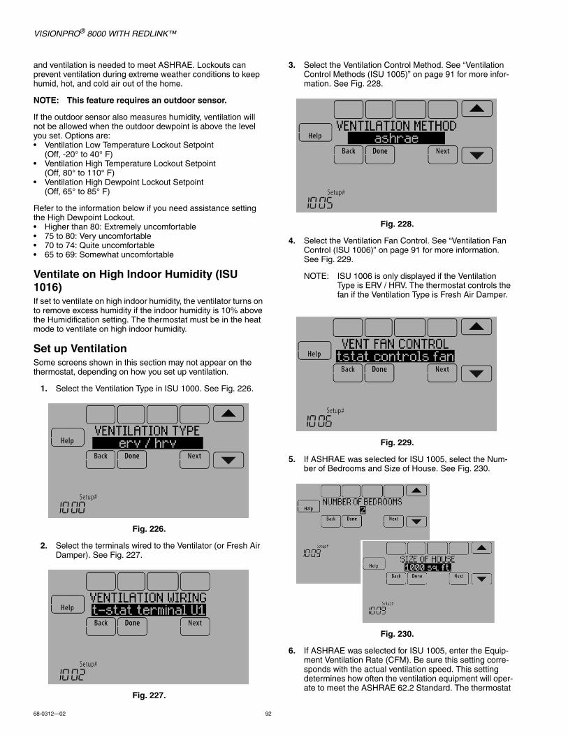
VISIONPRO® 8000 WITH REDLINK™
68-0312—02 92
and ventilation is needed to meet ASHRAE. Lockouts can prevent ventilation during extreme weather conditions to keep humid, hot, and cold air out of the home.
NOTE: This feature requires an outdoor sensor.
If the outdoor sensor also measures humidity, ventilation will not be allowed when the outdoor dewpoint is above the level you set. Options are:• Ventilation Low Temperature Lockout Setpoint
(Off, -20° to 40° F)• Ventilation High Temperature Lockout Setpoint
(Off, 80° to 110° F)• Ventilation High Dewpoint Lockout Setpoint
(Off, 65° to 85° F)
Refer to the information below if you need assistance setting the High Dewpoint Lockout. • Higher than 80: Extremely uncomfortable• 75 to 80: Very uncomfortable• 70 to 74: Quite uncomfortable• 65 to 69: Somewhat uncomfortable
Ventilate on High Indoor Humidity (ISU 1016)If set to ventilate on high indoor humidity, the ventilator turns on to remove excess humidity if the indoor humidity is 10% above the Humidification setting. The thermostat must be in the heat mode to ventilate on high indoor humidity.
Set up VentilationSome screens shown in this section may not appear on the thermostat, depending on how you set up ventilation.
1. Select the Ventilation Type in ISU 1000. See Fig. 226.
Fig. 226.
2. Select the terminals wired to the Ventilator (or Fresh Air Damper). See Fig. 227.
Fig. 227.
3. Select the Ventilation Control Method. See “Ventilation Control Methods (ISU 1005)” on page 91 for more infor-mation. See Fig. 228.
Fig. 228.
4. Select the Ventilation Fan Control. See “Ventilation Fan Control (ISU 1006)” on page 91 for more information. See Fig. 229.
NOTE: ISU 1006 is only displayed if the Ventilation Type is ERV / HRV. The thermostat controls the fan if the Ventilation Type is Fresh Air Damper.
Fig. 229.
5. If ASHRAE was selected for ISU 1005, select the Num-ber of Bedrooms and Size of House. See Fig. 230.
Fig. 230.
6. If ASHRAE was selected for ISU 1005, enter the Equip-ment Ventilation Rate (CFM). Be sure this setting corre-sponds with the actual ventilation speed. This setting determines how often the ventilation equipment will oper-ate to meet the ASHRAE 62.2 Standard. The thermostat
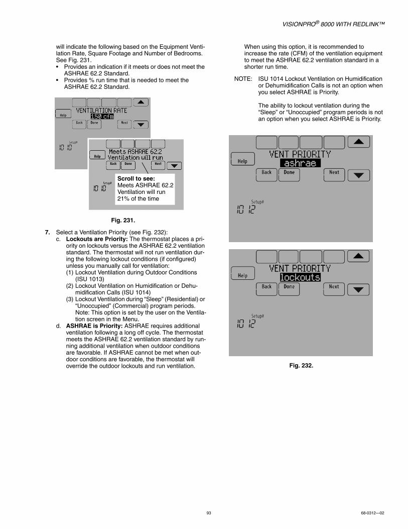
VISIONPRO® 8000 WITH REDLINK™
93 68-0312—02
will indicate the following based on the Equipment Venti-lation Rate, Square Footage and Number of Bedrooms. See Fig. 231.• Provides an indication if it meets or does not meet the
ASHRAE 62.2 Standard.• Provides % run time that is needed to meet the
ASHRAE 62.2 Standard.
Fig. 231.
7. Select a Ventilation Priority (see Fig. 232):c. Lockouts are Priority: The thermostat places a pri-
ority on lockouts versus the ASHRAE 62.2 ventilation standard. The thermostat will not run ventilation dur-ing the following lockout conditions (if configured) unless you manually call for ventilation:(1) Lockout Ventilation during Outdoor Conditions
(ISU 1013)(2) Lockout Ventilation on Humidification or Dehu-
midification Calls (ISU 1014)(3) Lockout Ventilation during “Sleep” (Residential) or
“Unoccupied” (Commercial) program periods. Note: This option is set by the user on the Ventila-tion screen in the Menu.
d. ASHRAE is Priority: ASHRAE requires additional ventilation following a long off cycle. The thermostat meets the ASHRAE 62.2 ventilation standard by run-ning additional ventilation when outdoor conditions are favorable. If ASHRAE cannot be met when out-door conditions are favorable, the thermostat will override the outdoor lockouts and run ventilation.
When using this option, it is recommended to increase the rate (CFM) of the ventilation equipment to meet the ASHRAE 62.2 ventilation standard in a shorter run time.
NOTE: ISU 1014 Lockout Ventilation on Humidification or Dehumidification Calls is not an option when you select ASHRAE is Priority.
The ability to lockout ventilation during the “Sleep” or “Unoccupied” program periods is not an option when you select ASHRAE is Priority.
Fig. 232.
Scroll to see:Meets ASHRAE 62.2Ventilation will run21% of the time
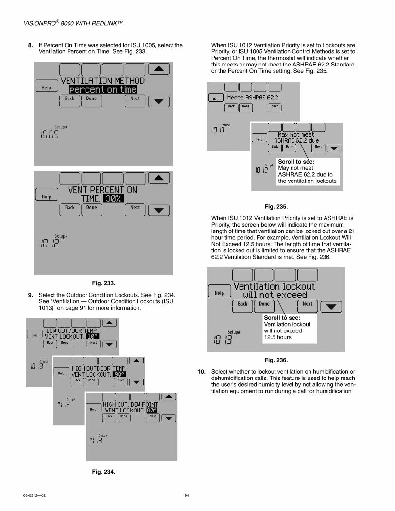
VISIONPRO® 8000 WITH REDLINK™
68-0312—02 94
8. If Percent On Time was selected for ISU 1005, select the Ventilation Percent on Time. See Fig. 233.
Fig. 233.
9. Select the Outdoor Condition Lockouts. See Fig. 234. See “Ventilation — Outdoor Condition Lockouts (ISU 1013)” on page 91 for more information.
Fig. 234.
When ISU 1012 Ventilation Priority is set to Lockouts are Priority, or ISU 1005 Ventilation Control Methods is set to Percent On Time, the thermostat will indicate whether this meets or may not meet the ASHRAE 62.2 Standard or the Percent On Time setting. See Fig. 235.
Fig. 235.
When ISU 1012 Ventilation Priority is set to ASHRAE is Priority, the screen below will indicate the maximum length of time that ventilation can be locked out over a 21 hour time period. For example, Ventilation Lockout Will Not Exceed 12.5 hours. The length of time that ventila-tion is locked out is limited to ensure that the ASHRAE 62.2 Ventilation Standard is met. See Fig. 236.
Fig. 236.
10. Select whether to lockout ventilation on humidification or dehumidification calls. This feature is used to help reach the user's desired humidity level by not allowing the ven-tilation equipment to run during a call for humidification
Scroll to see:May not meet ASHRAE 62.2 due to the ventilation lockouts
Scroll to see:Ventilation lockout will not exceed 12.5 hours
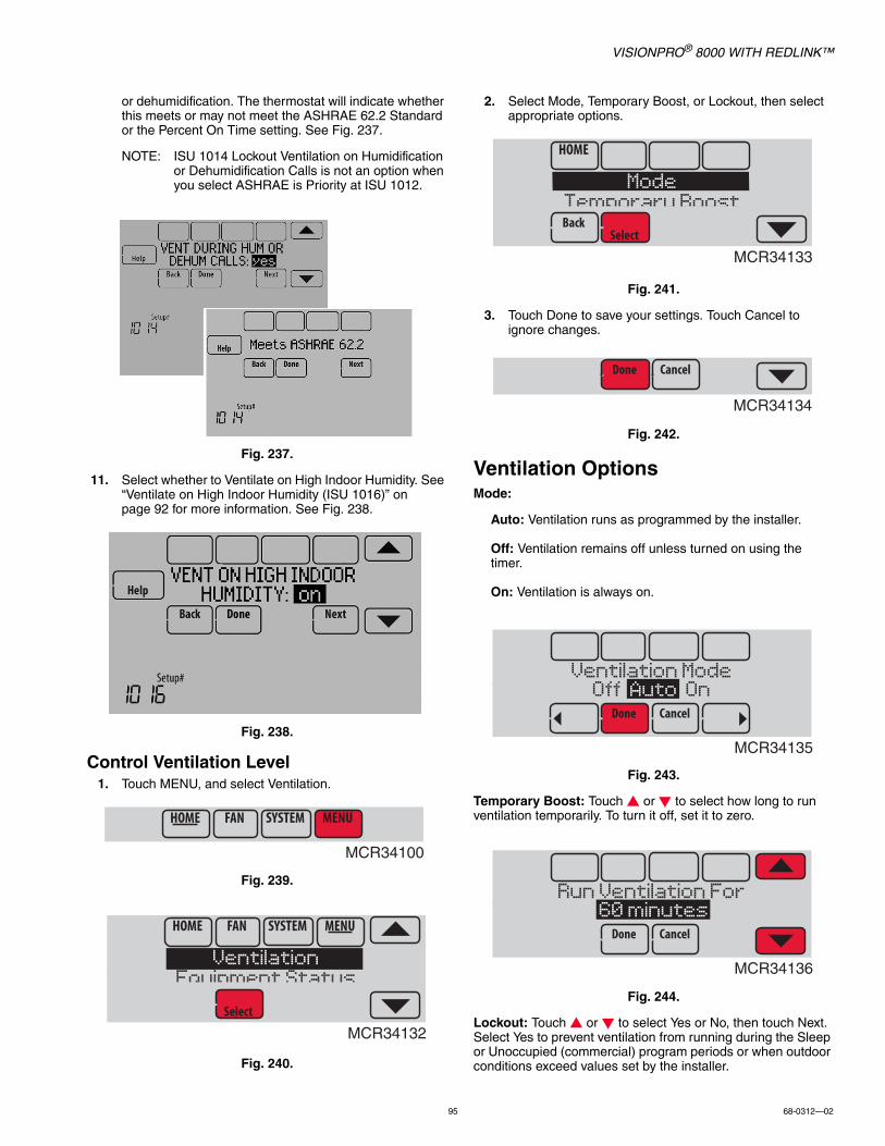
VISIONPRO® 8000 WITH REDLINK™
95 68-0312—02
or dehumidification. The thermostat will indicate whether this meets or may not meet the ASHRAE 62.2 Standard or the Percent On Time setting. See Fig. 237.
NOTE: ISU 1014 Lockout Ventilation on Humidification or Dehumidification Calls is not an option when you select ASHRAE is Priority at ISU 1012.
Fig. 237.
11. Select whether to Ventilate on High Indoor Humidity. See “Ventilate on High Indoor Humidity (ISU 1016)” on page 92 for more information. See Fig. 238.
Fig. 238.
Control Ventilation Level1. Touch MENU, and select Ventilation.
Fig. 239.
Fig. 240.
2. Select Mode, Temporary Boost, or Lockout, then select appropriate options.
Fig. 241.
3. Touch Done to save your settings. Touch Cancel to ignore changes.
Fig. 242.
Ventilation OptionsMode:
Auto: Ventilation runs as programmed by the installer.
Off: Ventilation remains off unless turned on using the timer.
On: Ventilation is always on.
Fig. 243.
Temporary Boost: Touch or to select how long to run ventilation temporarily. To turn it off, set it to zero.
Fig. 244.
Lockout: Touch or to select Yes or No, then touch Next. Select Yes to prevent ventilation from running during the Sleep or Unoccupied (commercial) program periods or when outdoor conditions exceed values set by the installer.
MCR34100
MCR34132
VentilationEquipment Status
MCR34133
ModeTemporary Boost
MCR34134
MCR34135
Ventilation ModeOff Auto On
MCR34136
Run Ventilation For 60 minutes
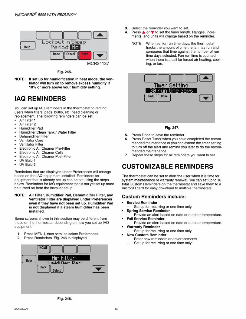
VISIONPRO® 8000 WITH REDLINK™
68-0312—02 96
Fig. 245.
NOTE: If set up for humidification in heat mode, the ven-tilator will turn on to remove excess humidity if 10% or more above your humidity setting.
IAQ REMINDERSYou can set up IAQ reminders in the thermostat to remind users when filters, pads, bulbs, etc. need cleaning or replacement. The following reminders can be set:• Air Filter 1• Air Filter 2• Humidifier Pad• Humidifier Clean Tank / Water Filter• Dehumidifier Filter• Ventilator Core• Ventilator Filter• Electronic Air Cleaner Pre-Filter• Electronic Air Cleaner Cells• Electronic Air Cleaner Post-Filter• UV Bulb 1• UV Bulb 2
Reminders that are displayed under Preferences will change based on the IAQ equipment installed. Reminders for equipment that is already set up can be set using the steps below. Reminders for IAQ equipment that is not yet set up must be turned on from the installer setup.
NOTE: Air Filter, Humidifier Pad, Dehumidifier Filter, and Ventilator Filter are displayed under Preferences even if they have not been set up. Humidifier Pad is not displayed if a steam humidifier has been installed.
Some screens shown in this section may be different from those on the thermostat, depending on how you set up IAQ equipment.
1. Press MENU, then scroll to select Preferences.2. Press Reminders. Fig. 246 is displayed.
Fig. 246.
3. Select the reminder you want to set.4. Press or to set the timer length. Ranges, incre-
ments, and units will change based on the reminder.
NOTE: When set for run time days, the thermostat tracks the amount of time the fan has run and compares that time against the number of run time days selected. Fan run time is counted when there is a call for forced air heating, cool-ing, or fan.
Fig. 247.
5. Press Done to save the reminder.6. Press Reset Timer when you have completed the recom-
mended maintenance or you can extend the timer setting to turn off the alert and remind you later to do the recom-mended maintenance.
7. Repeat these steps for all reminders you want to set.
CUSTOMIZABLE REMINDERSThe thermostat can be set to alert the user when it is time for system maintenance or warranty renewal. You can set up to 10 total Custom Reminders on the thermostat and save them to a microSD card for easy download to multiple thermostats.
Custom Reminders include:• Service Reminder
— Set up for recurring or one time only.• Spring Service Reminder
— Provide an alert based on date or outdoor temperature.• Fall Service Reminder
— Provide an alert based on date or outdoor temperature.• Warranty Reminder
— Set up for recurring or one time only.• New Custom Reminder
— Enter new reminders or advertisements— Set up for recurring or one time only.
MCR34137
Lockout in Sleep Period: No
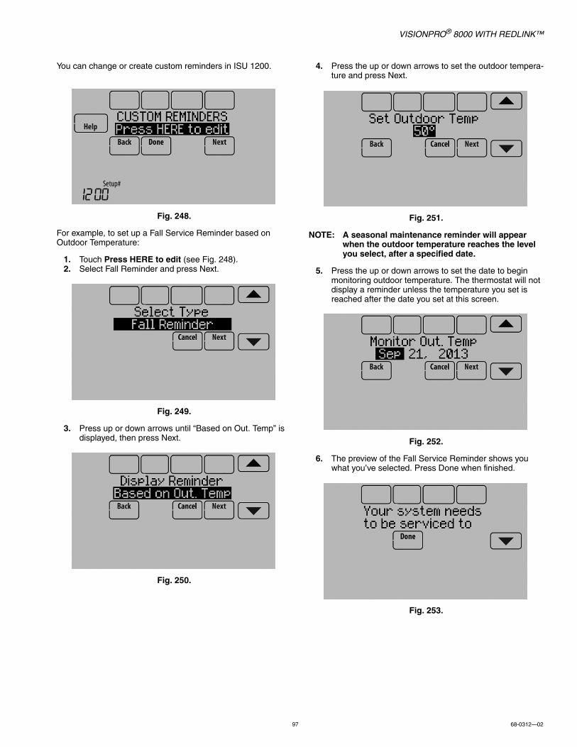
VISIONPRO® 8000 WITH REDLINK™
97 68-0312—02
You can change or create custom reminders in ISU 1200.
Fig. 248.
For example, to set up a Fall Service Reminder based on Outdoor Temperature:
1. Touch Press HERE to edit (see Fig. 248).2. Select Fall Reminder and press Next.
Fig. 249.
3. Press up or down arrows until “Based on Out. Temp” is displayed, then press Next.
Fig. 250.
4. Press the up or down arrows to set the outdoor tempera-ture and press Next.
Fig. 251.
NOTE: A seasonal maintenance reminder will appear when the outdoor temperature reaches the level you select, after a specified date.
5. Press the up or down arrows to set the date to begin monitoring outdoor temperature. The thermostat will not display a reminder unless the temperature you set is reached after the date you set at this screen.
Fig. 252.
6. The preview of the Fall Service Reminder shows you what you’ve selected. Press Done when finished.
Fig. 253.

VISIONPRO® 8000 WITH REDLINK™
68-0312—02 98
7. When the user touches Press HERE for info on the Home Screen, the reminder message will be displayed.
Fig. 254.
8. Pressing Select displays options for addressing the Fall Service Reminder message:• View More Info• Remind Me Later• Dismiss• View Dealer Info
Fig. 255.
9. Selecting View More Info displays the Fall Service Reminder message.
Fig. 256.
10. To clear the Alert, (and turn off the Red Alert Light on the thermostat), select Dismiss.
To create a new custom reminder:1. Touch Press HERE to edit at ISU 1200 (see Fig. 248).2. Press up or down arrows until Custom Reminder is dis-
played, then press Next (Fig. 257).
Fig. 257.
3. Touch Press HERE to edit to set the name of the reminder (Fig. 258).
Fig. 258.
4. Use the arrows, Delete, and Space buttons to enter the name of the reminder, and press Done.
Fig. 259.
Scroll to see:Your system needsto be serviced toprepare for theupcoming fallseason. Pleasecall your dealer.

VISIONPRO® 8000 WITH REDLINK™
99 68-0312—02
5. Touch Press HERE to edit to set the reminder message (see Fig. 260).
Fig. 260.
6. Use the arrows, Delete, and Space buttons to enter the reminder message, and press Done.
Fig. 261.
7. Press the up or down arrows to set the date when the New Custom Reminder should appear, and press Next.
Fig. 262.
8. Select whether you want the reminder to appear only once or to be recurring, and press Next.
Fig. 263.
9. If Recurring, select how often you want the reminder to appear and press Next.
Fig. 264.
10. The preview of the custom reminder shows you what you’ve selected. You can load Custom Reminders to a microSD card to transfer from one thermostat to another.
11. The New Custom Reminder will look like this on the Home Screen:
Fig. 265.
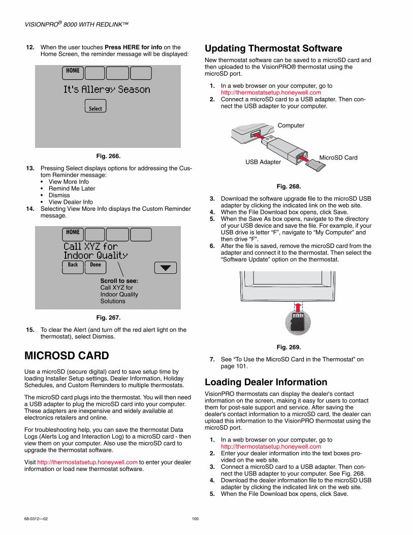
VISIONPRO® 8000 WITH REDLINK™
68-0312—02 100
12. When the user touches Press HERE for info on the Home Screen, the reminder message will be displayed:
Fig. 266.
13. Pressing Select displays options for addressing the Cus-tom Reminder message:• View More Info• Remind Me Later• Dismiss• View Dealer Info
14. Selecting View More Info displays the Custom Reminder message.
Fig. 267.
15. To clear the Alert (and turn off the red alert light on the thermostat), select Dismiss.
MICROSD CARDUse a microSD (secure digital) card to save setup time by loading Installer Setup settings, Dealer Information, Holiday Schedules, and Custom Reminders to multiple thermostats.
The microSD card plugs into the thermostat. You will then need a USB adapter to plug the microSD card into your computer. These adapters are inexpensive and widely available at electronics retailers and online.
For troubleshooting help, you can save the thermostat Data Logs (Alerts Log and Interaction Log) to a microSD card - then view them on your computer. Also use the microSD card to upgrade the thermostat software.
Visit http://thermostatsetup.honeywell.com to enter your dealer information or load new thermostat software.
Updating Thermostat SoftwareNew thermostat software can be saved to a microSD card and then uploaded to the VisionPRO® thermostat using the microSD port.
1. In a web browser on your computer, go to http://thermostatsetup.honeywell.com
2. Connect a microSD card to a USB adapter. Then con-nect the USB adapter to your computer.
Fig. 268.
3. Download the software upgrade file to the microSD USB adapter by clicking the indicated link on the web site.
4. When the File Download box opens, click Save.5. When the Save As box opens, navigate to the directory
of your USB device and save the file. For example, if your USB drive is letter “F”, navigate to “My Computer” and then drive “F”.
6. After the file is saved, remove the microSD card from the adapter and connect it to the thermostat. Then select the “Software Update” option on the thermostat.
Fig. 269.
7. See “To Use the MicroSD Card in the Thermostat” on page 101.
Loading Dealer InformationVisionPRO thermostats can display the dealer's contact information on the screen, making it easy for users to contact them for post-sale support and service. After saving the dealer's contact information to a microSD card, the dealer can upload this information to the VisionPRO thermostat using the microSD port.
1. In a web browser on your computer, go to http://thermostatsetup.honeywell.com
2. Enter your dealer information into the text boxes pro-vided on the web site.
3. Connect a microSD card to a USB adapter. Then con-nect the USB adapter to your computer. See Fig. 268.
4. Download the dealer information file to the microSD USB adapter by clicking the indicated link on the web site.
5. When the File Download box opens, click Save.
Scroll to see:Call XYZ for Indoor Quality Solutions
Computer
USB AdapterMicroSD Card
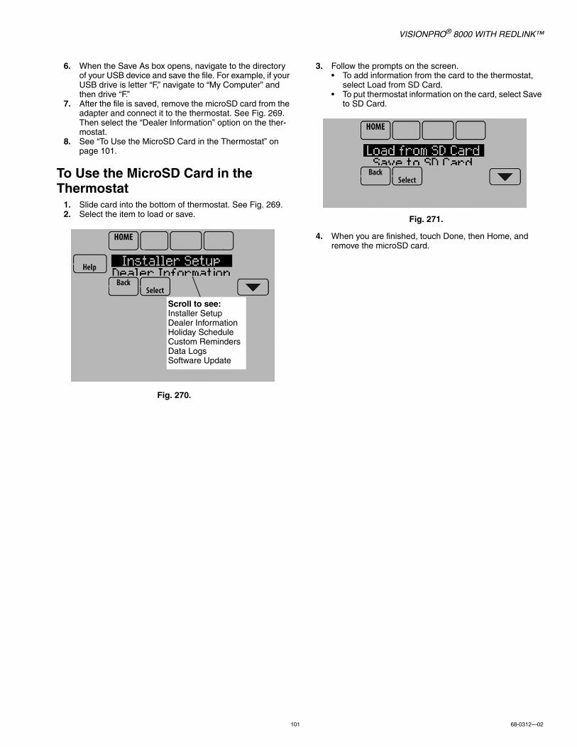
VISIONPRO® 8000 WITH REDLINK™
101 68-0312—02
6. When the Save As box opens, navigate to the directory of your USB device and save the file. For example, if your USB drive is letter “F,” navigate to “My Computer” and then drive “F.”
7. After the file is saved, remove the microSD card from the adapter and connect it to the thermostat. See Fig. 269. Then select the “Dealer Information” option on the ther-mostat.
8. See “To Use the MicroSD Card in the Thermostat” on page 101.
To Use the MicroSD Card in the Thermostat
1. Slide card into the bottom of thermostat. See Fig. 269.2. Select the item to load or save.
Fig. 270.
3. Follow the prompts on the screen.• To add information from the card to the thermostat,
select Load from SD Card.• To put thermostat information on the card, select Save
to SD Card.
Fig. 271.
4. When you are finished, touch Done, then Home, and remove the microSD card.
Scroll to see:Installer SetupDealer InformationHoliday ScheduleCustom RemindersData LogsSoftware Update
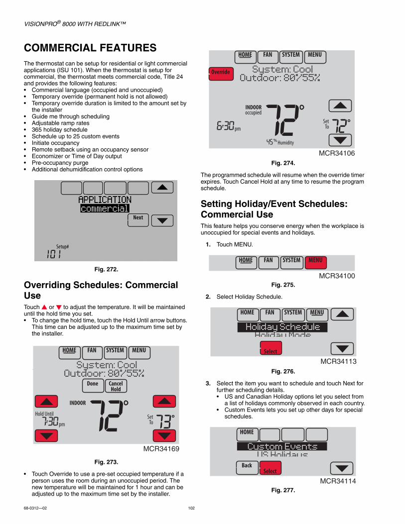
VISIONPRO® 8000 WITH REDLINK™
68-0312—02 102
COMMERCIAL FEATURESThe thermostat can be setup for residential or light commercial applications (ISU 101). When the thermostat is setup for commercial, the thermostat meets commercial code, Title 24 and provides the following features:• Commercial language (occupied and unoccupied)• Temporary override (permanent hold is not allowed)• Temporary override duration is limited to the amount set by
the installer• Guide me through scheduling• Adjustable ramp rates• 365 holiday schedule• Schedule up to 25 custom events• Initiate occupancy• Remote setback using an occupancy sensor• Economizer or Time of Day output• Pre-occupancy purge• Additional dehumidification control options
Fig. 272.
Overriding Schedules: Commercial UseTouch or to adjust the temperature. It will be maintained until the hold time you set.• To change the hold time, touch the Hold Until arrow buttons.
This time can be adjusted up to the maximum time set by the installer.
Fig. 273.
• Touch Override to use a pre-set occupied temperature if a person uses the room during an unoccupied period. The new temperature will be maintained for 1 hour and can be adjusted up to the maximum time set by the installer.
Fig. 274.
The programmed schedule will resume when the override timer expires. Touch Cancel Hold at any time to resume the program schedule.
Setting Holiday/Event Schedules: Commercial UseThis feature helps you conserve energy when the workplace is unoccupied for special events and holidays.
1. Touch MENU.
Fig. 275.
2. Select Holiday Schedule.
Fig. 276.
3. Select the item you want to schedule and touch Next for further scheduling details.• US and Canadian Holiday options let you select from
a list of holidays commonly observed in each country.• Custom Events lets you set up other days for special
schedules.
Fig. 277.
MCR34169
MCR34106
MCR34100
MCR34113
Holiday ScheduleHoliday Mode
MCR34114
Custom EventsUS Holidays
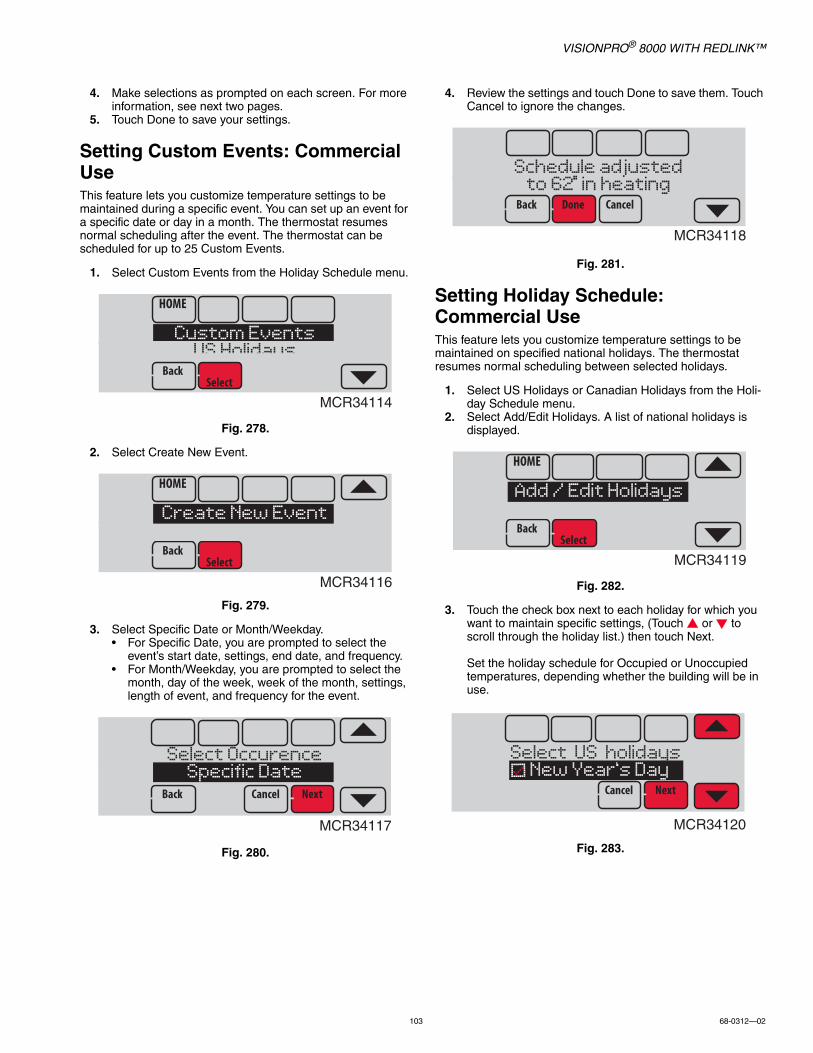
VISIONPRO® 8000 WITH REDLINK™
103 68-0312—02
4. Make selections as prompted on each screen. For more information, see next two pages.
5. Touch Done to save your settings.
Setting Custom Events: Commercial UseThis feature lets you customize temperature settings to be maintained during a specific event. You can set up an event for a specific date or day in a month. The thermostat resumes normal scheduling after the event. The thermostat can be scheduled for up to 25 Custom Events.
1. Select Custom Events from the Holiday Schedule menu.
Fig. 278.
2. Select Create New Event.
Fig. 279.
3. Select Specific Date or Month/Weekday.• For Specific Date, you are prompted to select the
event’s start date, settings, end date, and frequency.• For Month/Weekday, you are prompted to select the
month, day of the week, week of the month, settings, length of event, and frequency for the event.
Fig. 280.
4. Review the settings and touch Done to save them. Touch Cancel to ignore the changes.
Fig. 281.
Setting Holiday Schedule: Commercial UseThis feature lets you customize temperature settings to be maintained on specified national holidays. The thermostat resumes normal scheduling between selected holidays.
1. Select US Holidays or Canadian Holidays from the Holi-day Schedule menu.
2. Select Add/Edit Holidays. A list of national holidays is displayed.
Fig. 282.
3. Touch the check box next to each holiday for which you want to maintain specific settings, (Touch or to scroll through the holiday list.) then touch Next.
Set the holiday schedule for Occupied or Unoccupied temperatures, depending whether the building will be in use.
Fig. 283.
MCR34114
Custom EventsUS Holidays
MCR34116
Create New Event
MCR34117
Select OccurenceSpecific Date
MCR34118
Schedule adjustedto 62 in heating
MCR34119
Add / Edit Holidays
MCR34120
Select US holidays New Year’s Day

VISIONPRO® 8000 WITH REDLINK™
68-0312—02 104
4. Touch or to select the Heat and Cool temperatures.
Fig. 284.
5. Review the settings and touch Done to save them. Touch Cancel to ignore changes.
Setting Holiday Override: Commercial UseThis feature lets you customize temperature settings to be maintained from now until a specified date. The thermostat resumes normal scheduling on the date you select.
1. Touch MENU.
Fig. 285.
2. Select Holiday Mode to display Temperature While Away.
Fig. 286.
3. Touch or to select the Heat and Cool temperatures, then touch Next to select return date.
Fig. 287.
4. Review the settings and touch Done to save them. Touch Cancel to ignore the changes.
NOTE: The cool temperature can only be set higher than the unoccupied program setting and the heat tem-perature can only be set lower than the unoccu-pied program setting.
Initiating Occupancy Mode: Commercial UseThis feature keeps temperature at an energy saving level until you touch Press HERE to Start Occupancy. When you arrive, touch the message to maintain a comfortable temperature while the room is occupied.
Fig. 288.
Touch the or buttons to set the temperature or the Hold Until time. The temperature is maintained until the time you set. Temperature returns to an energy-saving level after the timer expires, or the “Occupied” period ends.
NOTE: This feature is available only when programmed by the installer.
MCR34121
TemperatureDuring Holiday
MCR34100
MCR34122
Holiday ModeEquipment Status
MCR34123
TemperatureWhile Away
M34127
Press HERE toStart Occupancy

VISIONPRO® 8000 WITH REDLINK™
105 68-0312—02
Ramp Rates (Commercial Use)When the ramp rate is set to Off, the thermostat begins recovery at the scheduled time.
When a ramp rate is set, recovery begins early to reach the setpoint by the program time. Based on your recovery ramp setting and how far the thermostat is set back, the thermostat determines how early to turn on the system.
If an outdoor sensor is installed, you can set outdoor temperatures for mild, cold and hot days in your region. By setting these outdoor temperatures, the thermostat will automatically adjust the ramp rate based on outdoor conditions. This allows the thermostat to save energy by starting recovery at the optimum time as outdoor conditions change.
NOTE: The thermostat uses an adjustable ramp rate when the thermostat is setup for commercial. This allows the thermostat to recover on time during changing conditions (occupancy changes, tem-perature overrides, load conditions, opening/clos-ing of doors etc) which are common in commercial applications.
Fig. 289.
Fig. 290.
Remote Setback (Commercial Use)The thermostat allows you to do REMOTE SETBACK when set up for commercial use. This feature requires an occupancy sensor connected to the S1, S2, S3 or S4 terminals at the Equipment Interface Module.
During Occupied program periods, an occupancy sensor directs the thermostat to go to REMOTE SETBACK settings when the room is empty. If someone is in the room, it uses the Occupied program period settings. The thermostat ignores the occupancy sensor during Unoccupied program periods.
If the thermostat is set up to be non-programmable, the sensor directs the thermostat to go to REMOTE SETBACK settings when the room is empty. If someone is in the room, then it follows the settings set by the user.
Depending on how your thermostat was installed, it may delay for up to 30 minutes before switching to REMOTE SETBACK settings. This delay allows the room to stay comfortable if the room is unoccupied for only a short time.
Set Up Remote Setback1. Select “Remote Setback” as shown in Fig. 291.
Fig. 291.
2. Select the terminals wired to the Remote Setback Dry Contact device (occupancy sensor) and press Next.
Fig. 292.
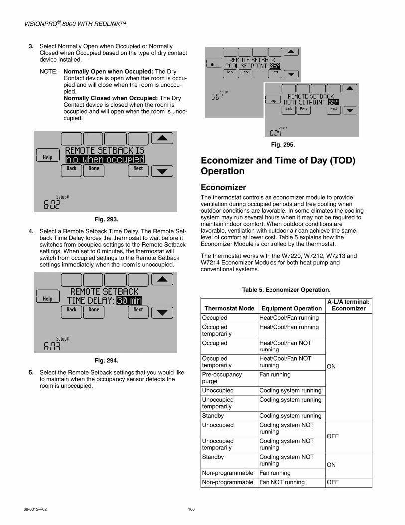
VISIONPRO® 8000 WITH REDLINK™
68-0312—02 106
3. Select Normally Open when Occupied or Normally Closed when Occupied based on the type of dry contact device installed.
NOTE: Normally Open when Occupied: The Dry Contact device is open when the room is occu-pied and will close when the room is unoccu-pied.Normally Closed when Occupied: The Dry Contact device is closed when the room is occupied and will open when the room is unoc-cupied.
Fig. 293.
4. Select a Remote Setback Time Delay. The Remote Set-back Time Delay forces the thermostat to wait before it switches from occupied settings to the Remote Setback settings. When set to 0 minutes, the thermostat will switch from occupied settings to the Remote Setback settings immediately when the room is unoccupied.
Fig. 294.
5. Select the Remote Setback settings that you would like to maintain when the occupancy sensor detects the room is unoccupied.
Fig. 295.
Economizer and Time of Day (TOD) Operation
EconomizerThe thermostat controls an economizer module to provide ventilation during occupied periods and free cooling when outdoor conditions are favorable. In some climates the cooling system may run several hours when it may not be required to maintain indoor comfort. When outdoor conditions are favorable, ventilation with outdoor air can achieve the same level of comfort at lower cost. Table 5 explains how the Economizer Module is controlled by the thermostat.
The thermostat works with the W7220, W7212, W7213 and W7214 Economizer Modules for both heat pump and conventional systems.
Table 5. Economizer Operation.
Thermostat Mode Equipment OperationA-L/A terminal:
Economizer
Occupied Heat/Cool/Fan running
ON
Occupied temporarily
Heat/Cool/Fan running
Occupied Heat/Cool/Fan NOT running
Occupied temporarily
Heat/Cool/Fan NOT running
Pre-occupancy purge
Fan running
Unoccupied Cooling system running
Unoccupied temporarily
Cooling system running
Standby Cooling system running
Unoccupied Cooling system NOT running
OFFUnoccupied temporarily
Cooling system NOT running
Standby Cooling system NOT running ON
Non-programmable Fan running
Non-programmable Fan NOT running OFF

VISIONPRO® 8000 WITH REDLINK™
107 68-0312—02
Time of Day (TOD)The thermostat can be set up for a Time of Day output in the installer setup. This output is commonly used to control lighting panels, turning them on for occupied periods and off for unoccupied periods. Table 6 explains how the TOD feature works with various thermostat modes.
The Economizer Module and Time of Day output connect to the A-L/A terminal at the thermostat or EIM and are set up at ISU 222.
Fig. 296.
Pre-Occupancy PurgeThe thermostat can be set up for Pre-Occupancy Purge in the installer setup (ISU 401). When setup for Pre-Occupancy Purge, the thermostat runs the fan 1 to 3 hours before each occupied period to provide a comfortable workplace upon arrival. Options are Off and 1 to 3 hours.
Fig. 297.
Table 6. TOD Operation.
Thermostat ModeA-L/A terminal:
TOD
Occupied
ONOccupied temporarily
Temperature overrides
Unoccupied
OFFUnoccupied temporarily
Standby
Non-programmable

VISIONPRO® 8000 WITH REDLINK™
68-0312—02 108
Battery Replacement
ThermostatInstall fresh batteries when the REPLACE BATTERY warning begins flashing. The warning flashes about 60 days before batteries are depleted.
Fig. 298.
Even if the warning does not appear, it is recommended to replace batteries once a year, or before leaving home for more than a month.
Press the release button on top of the thermostat to remove it from the wall plate. Install 4 fresh AA alkaline batteries.
Fig. 299.
Portable Comfort Control
Install fresh batteries when the REPLACE BATTERY warning begins flashing. The warning flashes about 60 days before batteries are depleted.
The Portable Comfort Control will restore communication with the thermostat a few seconds after new batteries are installed.
Wireless Outdoor SensorReplace batteries in your outdoor sensor when a warning appears on the thermostat screen, about 60 days before batteries are depleted.
Fig. 300.
To replace the batteries:1. Remove the sensor from the bracket.2. Detach cover.3. Install 2 fresh AA lithium batteries.4. Replace cover and set sensor back into bracket.
The outdoor sensor will restore communication with the thermostat a few seconds after new batteries are installed.
MCR34144
Replace BatteriesPress HERE for info
M34071Thermostat(back view)
Wallplate
Thermostat
Button
MCR28475
M28896
SET TO
REPLACEBATTERY78 78
MCR34145
Outdoor Sensorhas low batteries
M32988MCR32937
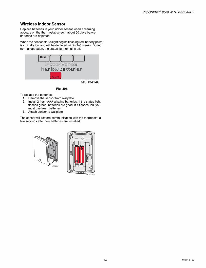
VISIONPRO® 8000 WITH REDLINK™
109 68-0312—02
Wireless Indoor SensorReplace batteries in your indoor sensor when a warning appears on the thermostat screen, about 60 days before batteries are depleted.
When the sensor status light begins flashing red, battery power is critically low and will be depleted within 2–3 weeks. During normal operation, the status light remains off.
Fig. 301.
To replace the batteries:1. Remove the sensor from wallplate.2. Install 2 fresh AAA alkaline batteries. If the status light
flashes green, batteries are good; if it flashes red, you must use fresh batteries.
3. Attach sensor to wallplate.
The sensor will restore communication with the thermostat a few seconds after new batteries are installed.
MCR34146
Indoor Sensorhas low batteries
M32990
MCR32933
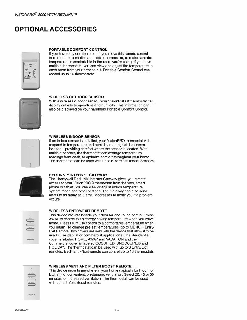
VISIONPRO® 8000 WITH REDLINK™
68-0312—02 110
OPTIONAL ACCESSORIES
PORTABLE COMFORT CONTROLIf you have only one thermostat, you move this remote control from room to room (like a portable thermostat), to make sure the temperature is comfortable in the room you’re using. If you have multiple thermostats, you can view and adjust the temperature in each room from your armchair. A Portable Comfort Control can control up to 16 thermostats.
WIRELESS OUTDOOR SENSORWith a wireless outdoor sensor, your VisionPRO® thermostat can display outside temperature and humidity. This information can also be displayed on your handheld Portable Comfort Control.
WIRELESS INDOOR SENSORIf an indoor sensor is installed, your VisionPRO thermostat will respond to temperature and humidity readings at the sensor location—providing comfort where the sensor is located. With multiple sensors, the thermostat can average temperature readings from each, to optimize comfort throughout your home. The thermostat can be used with up to 6 Wireless Indoor Sensors.
REDLINK™ INTERNET GATEWAYThe Honeywell RedLINK Internet Gateway gives you remote access to your VisionPRO® thermostat from the web, smart phone or tablet. You can view or adjust indoor temperature, system mode and other settings. The Gateway can also send alerts to as many as 6 email addresses to notify you if a problem occurs.
WIRELESS ENTRY/EXIT REMOTEThis device mounts beside your door for one-touch control. Press AWAY to control to an energy saving temperature when you leave home. Press HOME to control to a comfortable temperature when you return. To change pre-set temperatures, go to MENU > Entry/Exit Remote. Two covers are sold with the device that allow it to be used in residential or commercial applications. The Residential cover is labeled HOME, AWAY and VACATION and the Commercial cover is labeled OCCUPIED, UNOCCUPIED and HOLIDAY. The thermostat can be used with up to 3 Entry/Exit remotes. Each Entry/Exit remote can control up to 16 thermostats.
WIRELESS VENT AND FILTER BOOST REMOTEThis device mounts anywhere in your home (typically bathroom or kitchen) for convenient, on-demand ventilation. Select 20, 40 or 60 minutes for increased ventilation. The thermostat can be used with up to 6 Vent Boost remotes.

VISIONPRO® 8000 WITH REDLINK™
111 68-0312—02
PORTABLE COMFORT CONTROLThe Portable Comfort Control communicates wirelessly with the thermostat, and can control up to 16 thermostats.
NOTE: Each thermostat can only be connected to 1 Portable Comfort Control.
If you have one thermostat, you move this remote control from room to room (like a portable thermostat), to make sure the temperature is comfortable in the room you’re using. If you have multiple thermostats, you can view and adjust the temperature in each room from the Portable Comfort Control.
If you have one thermostat, temperature is measured at the thermostat (Fig. 302) or Portable Comfort Control (Fig. 303), as you choose.
Fig. 302. Reading temperature at the thermostat.
Fig. 303. Reading temperature at the Portable Comfort Control.
If the thermostat is being averaged with remote indoor sensors, and you select THERMOSTAT on the Portable Comfort Control, you will see the temperature average from the remote indoor sensors and the thermostat.
NOTE: If the thermostat is not part of the temperature average, then you will only see the temperature average from the remote indoor sensors when you select THERMOSTAT on the Portable Comfort Control.
If the thermostat is being averaged with remote indoor sensors, and you select THIS DEVICE on the Portable Comfort Control, you will see the temperature measured at the Portable Comfort Control only.
If you have multiple thermostats, temperature is measured at each thermostat. Press the TOGGLE ZONE arrows to choose which room to display and adjust. See Fig. 304.
Fig. 304. Portable Comfort Control used with Multiple Thermostats. Temperature is measured at each
thermostat.
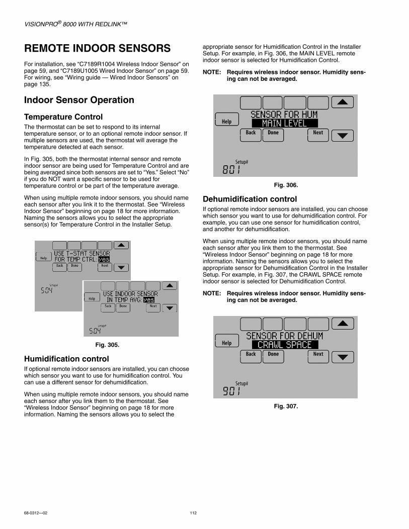
VISIONPRO® 8000 WITH REDLINK™
68-0312—02 112
REMOTE INDOOR SENSORSFor installation, see “C7189R1004 Wireless Indoor Sensor” on page 59, and “C7189U1005 Wired Indoor Sensor” on page 59. For wiring, see “Wiring guide — Wired Indoor Sensors” on page 135.
Indoor Sensor Operation
Temperature ControlThe thermostat can be set to respond to its internal temperature sensor, or to an optional remote indoor sensor. If multiple sensors are used, the thermostat will average the temperature detected at each sensor.
In Fig. 305, both the thermostat internal sensor and remote indoor sensor are being used for Temperature Control and are being averaged since both sensors are set to “Yes.” Select “No” if you do NOT want a specific sensor to be used for temperature control or be part of the temperature average.
When using multiple remote indoor sensors, you should name each sensor after you link it to the thermostat. See “Wireless Indoor Sensor” beginning on page 18 for more information. Naming the sensors allows you to select the appropriate sensor(s) for Temperature Control in the Installer Setup.
Fig. 305.
Humidification controlIf optional remote indoor sensors are installed, you can choose which sensor you want to use for humidification control. You can use a different sensor for dehumidification.
When using multiple remote indoor sensors, you should name each sensor after you link them to the thermostat. See “Wireless Indoor Sensor” beginning on page 18 for more information. Naming the sensors allows you to select the
appropriate sensor for Humidification Control in the Installer Setup. For example, in Fig. 306, the MAIN LEVEL remote indoor sensor is selected for Humidification Control.
NOTE: Requires wireless indoor sensor. Humidity sens-ing can not be averaged.
Fig. 306.
Dehumidification controlIf optional remote indoor sensors are installed, you can choose which sensor you want to use for dehumidification control. For example, you can use one sensor for humidification control, and another for dehumidification.
When using multiple remote indoor sensors, you should name each sensor after you link them to the thermostat. See “Wireless Indoor Sensor” beginning on page 18 for more information. Naming the sensors allows you to select the appropriate sensor for Dehumidification Control in the Installer Setup. For example, in Fig. 307, the CRAWL SPACE remote indoor sensor is selected for Dehumidification Control.
NOTE: Requires wireless indoor sensor. Humidity sens-ing can not be averaged.
Fig. 307.
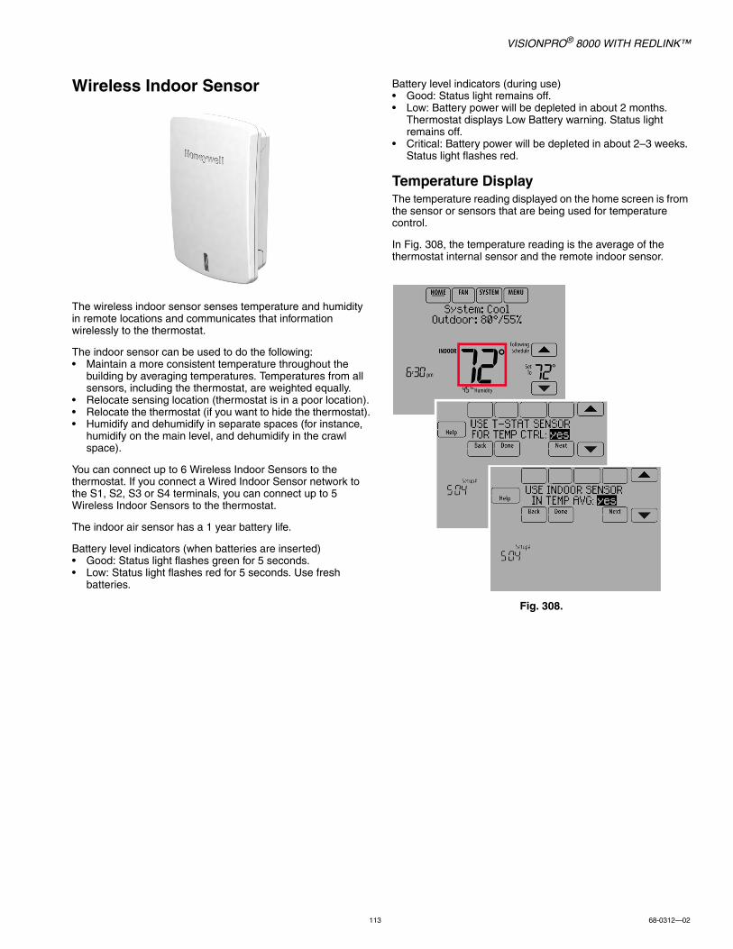
VISIONPRO® 8000 WITH REDLINK™
113 68-0312—02
Wireless Indoor Sensor
The wireless indoor sensor senses temperature and humidity in remote locations and communicates that information wirelessly to the thermostat.
The indoor sensor can be used to do the following:• Maintain a more consistent temperature throughout the
building by averaging temperatures. Temperatures from all sensors, including the thermostat, are weighted equally.
• Relocate sensing location (thermostat is in a poor location).• Relocate the thermostat (if you want to hide the thermostat).• Humidify and dehumidify in separate spaces (for instance,
humidify on the main level, and dehumidify in the crawl space).
You can connect up to 6 Wireless Indoor Sensors to the thermostat. If you connect a Wired Indoor Sensor network to the S1, S2, S3 or S4 terminals, you can connect up to 5 Wireless Indoor Sensors to the thermostat.
The indoor air sensor has a 1 year battery life.
Battery level indicators (when batteries are inserted)• Good: Status light flashes green for 5 seconds.• Low: Status light flashes red for 5 seconds. Use fresh
batteries.
Battery level indicators (during use)• Good: Status light remains off.• Low: Battery power will be depleted in about 2 months.
Thermostat displays Low Battery warning. Status light remains off.
• Critical: Battery power will be depleted in about 2–3 weeks. Status light flashes red.
Temperature DisplayThe temperature reading displayed on the home screen is from the sensor or sensors that are being used for temperature control.
In Fig. 308, the temperature reading is the average of the thermostat internal sensor and the remote indoor sensor.
Fig. 308.
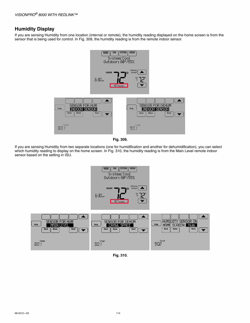
VISIONPRO® 8000 WITH REDLINK™
68-0312—02 114
Humidity DisplayIf you are sensing Humidity from one location (internal or remote), the humidity reading displayed on the home screen is from the sensor that is being used for control. In Fig. 309, the humidity reading is from the remote indoor sensor.
Fig. 309.
If you are sensing Humidity from two separate locations (one for humidification and another for dehumidification), you can select which humidity reading to display on the home screen. In Fig. 310, the humidity reading is from the Main Level remote indoor sensor based on the setting in ISU.
Fig. 310.

VISIONPRO® 8000 WITH REDLINK™
115 68-0312—02
Calibration - Outdoor SensorThe C7089U1006 Outdoor Sensor is calibrated at the factory and cannot be recalibrated in the field.
Calibration - Indoor SensorThe C7189U1005 Wall Mount Temperature Sensor is calibrated at the factory and cannot be recalibrated in the field.
Table 7. C7089U1006 Sensor Resistance at Outdoor Temperature.
Outdoor Temperature Ohms of
Resistance
Outdoor Temperature Ohms of
Resistance°F °C °F °C
-20 -28.9 106926 52 11.1 17136
-18 -27.8 100923 54 12.2 16387
-16 -26.7 95310 56 13.3 15675
-14 -25.6 90058 58 14.4 14999
-12 -24.4 85124 60 15.6 14356
-10 -23.3 80485 62 16.7 13743
-8 -22.2 76137 64 17.8 13161
-6 -21.1 72060 66 18.9 12607
-4 -20.0 68237 68 20.0 12081
-2 -18.9 64631 70 21.1 11578
0 -17.8 61246 72 22.2 11100
2 -16.7 58066 74 23.3 10644
4 -15.6 55077 76 24.4 10210
6 -14.4 53358 78 25.6 9795
8 -13.3 49598 80 26.7 9398
10 -12.2 47092 82 27.8 9020
12 -11.1 44732 84 28.9 8659
14 -10.0 42506 86 30.0 8315
16 -8.9 40394 88 31.1 7986
18 -7.8 38400 90 32.2 7672
20 -6.7 36519 92 33.3 7372
22 -5.6 34743 94 34.4 7086
24 -4.4 33063 96 35.6 6813
26 -3.3 31475 98 36.7 6551
28 -2.2 29975 100 37.8 6301
30 -1.1 28558 102 38.9 6062
32 0.0 27219 104 40.0 5834
34 1.1 25949 106 41.1 5614
36 2.2 24749 108 42.2 5404
38 3.3 23613 110 43.3 5203
40 4.4 22537 112 44.4 5010
42 5.6 21516 114 45.6 4826
44 6.7 20546 116 46.7 4649
46 7.8 19626 118 47.8 4479
48 8.9 18754 120 48.9 4317
50 10.0 17926 —
Table 8. C7189U1005 Sensor Resistance at Room Temperature.
Room Temperature Ohms of
Resistance
Room Temperature Ohms of
Resistance°F °C °F °C
40 4.4 22537 72 22.2 11100
42 5.6 21516 74 23.3 10644
44 6.7 20546 76 24.4 10210
46 7.8 19626 78 25.6 9795
48 8.9 18754 80 26.7 9398
50 10.0 17926 82 27.8 9020
52 11.1 17136 84 28.9 8659
54 12.2 16387 86 30.0 8315
56 13.3 15675 88 31.1 7986
58 14.4 14999 90 32.2 7672
60 15.6 14356 92 33.3 7372
62 16.7 13743 94 34.4 7086
64 17.8 13161 96 35.6 6813
66 18.9 12607 98 36.7 6551
68 20.0 12081 100 37.8 6301
70 21.1 11578 —
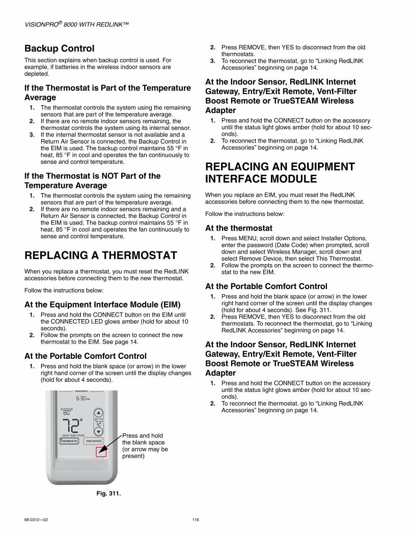
VISIONPRO® 8000 WITH REDLINK™
68-0312—02 116
Backup ControlThis section explains when backup control is used. For example, if batteries in the wireless indoor sensors are depleted.
If the Thermostat is Part of the Temperature Average
1. The thermostat controls the system using the remaining sensors that are part of the temperature average.
2. If there are no remote indoor sensors remaining, the thermostat controls the system using its internal sensor.
3. If the internal thermostat sensor is not available and a Return Air Sensor is connected, the Backup Control in the EIM is used. The backup control maintains 55 °F in heat, 85 °F in cool and operates the fan continuously to sense and control temperature.
If the Thermostat is NOT Part of the Temperature Average
1. The thermostat controls the system using the remaining sensors that are part of the temperature average.
2. If there are no remote indoor sensors remaining and a Return Air Sensor is connected, the Backup Control in the EIM is used. The backup control maintains 55 °F in heat, 85 °F in cool and operates the fan continuously to sense and control temperature.
REPLACING A THERMOSTATWhen you replace a thermostat, you must reset the RedLINK accessories before connecting them to the new thermostat.
Follow the instructions below:
At the Equipment Interface Module (EIM)1. Press and hold the CONNECT button on the EIM until
the CONNECTED LED glows amber (hold for about 10 seconds).
2. Follow the prompts on the screen to connect the new thermostat to the EIM. See page 14.
At the Portable Comfort Control1. Press and hold the blank space (or arrow) in the lower
right hand corner of the screen until the display changes (hold for about 4 seconds).
Fig. 311.
2. Press REMOVE, then YES to disconnect from the old thermostats.
3. To reconnect the thermostat, go to “Linking RedLINK Accessories” beginning on page 14.
At the Indoor Sensor, RedLINK Internet Gateway, Entry/Exit Remote, Vent-Filter Boost Remote or TrueSTEAM Wireless Adapter
1. Press and hold the CONNECT button on the accessory until the status light glows amber (hold for about 10 sec-onds).
2. To reconnect the thermostat, go to “Linking RedLINK Accessories” beginning on page 14.
REPLACING AN EQUIPMENT INTERFACE MODULEWhen you replace an EIM, you must reset the RedLINK accessories before connecting them to the new thermostat.
Follow the instructions below:
At the thermostat1. Press MENU, scroll down and select Installer Options,
enter the password (Date Code) when prompted, scroll down and select Wireless Manager, scroll down and select Remove Device, then select This Thermostat.
2. Follow the prompts on the screen to connect the thermo-stat to the new EIM.
At the Portable Comfort Control1. Press and hold the blank space (or arrow) in the lower
right hand corner of the screen until the display changes (hold for about 4 seconds). See Fig. 311.
2. Press REMOVE, then YES to disconnect from the old thermostats. To reconnect the thermostat, go to “Linking RedLINK Accessories” beginning on page 14.
At the Indoor Sensor, RedLINK Internet Gateway, Entry/Exit Remote, Vent-Filter Boost Remote or TrueSTEAM Wireless Adapter
1. Press and hold the CONNECT button on the accessory until the status light glows amber (hold for about 10 sec-onds).
2. To reconnect the thermostat, go to “Linking RedLINK Accessories” beginning on page 14.
Press and hold the blank space (or arrow may be present)

VISIONPRO® 8000 WITH REDLINK™
117 68-0312—02
WIRINGSee Table 9 for Equipment Interface Module terminal descriptions and Table 10 for thermostat terminal descriptions.
* Remove jumpers when separate transformers are used.† See “Wiring IAQ Equipment or a Heat/Cool Stage to the Universal Terminals” beginning on page 130.‡ See “Dry Contact Alerts” beginning on page 74 for wiring Dry Contact Devices to display alerts.
Table 9. Equipment Interface Module Terminal Designation Descriptions.
Conventional System Heat Pump
Terminal Description Terminal Description
C Common wire from 24 VAC transformer. C Common wire from 24 VAC transformer.
R* Power wire from 24 VAC transformer. R Power wire from 24 VAC transformer.
RH* Heating power RH Heating power
RC* Cooling power RC Cooling power
W Heat Stage 1 O/B Changeover valve for heat pumps
W2 Heat Stage 2 AUX 1 Backup Heat Stage 1/Emergency Heat Stage 1
W3 Heat Stage 3 AUX 2 Backup Heat Stage 2/Emergency Heat Stage 2
Y Compressor Stage 1 Y Compressor Stage 1
Y2 Compressor Stage 2 Y2 Compressor Stage 2
G Fan Relay G Fan Relay
A Connect to Economizer Module or Lighting Panel (TOD).
L/A Connect to Compressor Monitor, Zone Panel, Economizer Module or Lighting Panel (TOD).
U1 / U1†
U2 / U2†
U3 / U3†
Universal relay for humidification, dehumidification, ventilation, or a stage of heating/cooling. U terminals are dry contacts that require power.
U1 / U1†
U2 / U2†
U3 / U3†
Universal relay for humidification, dehumidification, ventilation, or a stage of heating/cooling. U terminals are dry contacts that require power.
S1 / S1‡
S2 / S2‡
S3 / S3‡
S4 / S4‡
Universal input for a wired indoor sensor, outdoor sensor, discharge sensor, return sensor, dry contact device for alerts or dry contact device for remote setback.
S1 / S1‡
S2 / S2‡
S3 / S3‡
S4 / S4‡
Universal input for a wired indoor sensor, outdoor sensor, discharge sensor, return sensor, dry contact device for alerts or dry contact device for remote setback.
ABCD
Connect to THM4000R1000 Wireless Adapter for extended wireless range.
ABCD
Connect to THM4000R1000 Wireless Adapter for extended wireless range.
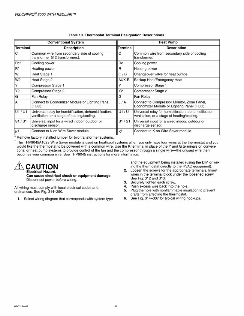
VISIONPRO® 8000 WITH REDLINK™
68-0312—02 118
* Remove factory installed jumper for two transformer systems.† The THP9045A1023 Wire Saver module is used on heat/cool systems when you only have four wires at the thermostat and you
would like the thermostat to be powered with a common wire. Use the K terminal in place of the Y and G terminals on conven-tional or heat pump systems to provide control of the fan and the compressor through a single wire—the unused wire then becomes your common wire. See THP9045 instructions for more information.
CAUTIONElectrical Hazard.Can cause electrical shock or equipment damage.Disconnect power before wiring.
All wiring must comply with local electrical codes and ordinances. See Fig. 314–350.
1. Select wiring diagram that corresponds with system type
and the equipment being installed (using the EIM or wir-ing the thermostat directly to the HVAC equipment).
2. Loosen the screws for the appropriate terminals. Insert wires in the terminal block under the loosened screw. See Fig. 312 and 313.
3. Securely tighten each screw.4. Push excess wire back into the hole.5. Plug the hole with nonflammable insulation to prevent
drafts from affecting the thermostat.6. See Fig. 314–337 for typical wiring hookups.
Table 10. Thermostat Terminal Designation Descriptions.
Conventional System Heat Pump
Terminal Description Terminal Description
C Common wire from secondary side of cooling transformer (if 2 transformers).
C Common wire from secondary side of cooling transformer.
Rc* Cooling power Rc Cooling power
R* Heating power R Heating power
W Heat Stage 1 O / B Changeover valve for heat pumps
W2 Heat Stage 2 AUX-E Backup Heat/Emergency Heat
Y Compressor Stage 1 Y Compressor Stage 1
Y2 Compressor Stage 2 Y2 Compressor Stage 2
G Fan Relay G Fan Relay
A Connect to Economizer Module or Lighting Panel (TOD).
L / A Connect to Compressor Monitor, Zone Panel, Economizer Module or Lighting Panel (TOD).
U1 / U1 Universal relay for humidification, dehumidification, ventilation, or a stage of heating/cooling.
U1 / U1 Universal relay for humidification, dehumidification, ventilation, or a stage of heating/cooling.
S1 / S1 Universal input for a wired indoor, outdoor or discharge sensor.
S1 / S1 Universal input for a wired indoor, outdoor or discharge sensor.
K† Connect to K on Wire Saver module. K† Connect to K on Wire Saver module.
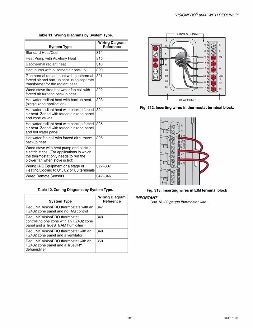
VISIONPRO® 8000 WITH REDLINK™
119 68-0312—02
Fig. 312. Inserting wires in thermostat terminal block.
Fig. 313. Inserting wires in EIM terminal block
IMPORTANTUse 18–22 gauge thermostat wire.
Table 11. Wiring Diagrams by System Type.
System TypeWiring Diagram
Reference
Standard Heat/Cool 314
Heat Pump with Auxiliary Heat 315
Geothermal radiant heat 316
Heat pump with oil forced air backup. 320
Geothermal radiant heat with geothermal forced air and backup heat using separate transformer for the radiant heat
321
Wood stove-fired hot water fan coil with forced air furnace backup heat
322
Hot water radiant heat with backup heat (single zone application)
323
Hot water radiant heat with backup forced air heat. Zoned with forced air zone panel and zone valves
324
Hot water radiant heat with backup forced air heat. Zoned with forced air zone panel and hot water panel.
325
Hot water fan coil with forced air furnace backup heat.
326
Wood stove with heat pump and backup electric strips. (For applications in which the thermostat only needs to run the blower fan when stove is hot).
Wiring IAQ Equipment or a stage of Heating/Cooling to U1, U2 or U3 terminals
327–337
Wired Remote Sensors 342–346
Table 12. Zoning Diagrams by System Type.
System TypeWiring Diagram
Reference
RedLINK VisionPRO thermostats with an HZ432 zone panel and no IAQ control
347
RedLINK VisionPRO thermostat controlling one zone with an HZ432 zone panel and a TrueSTEAM humidifier
348
RedLINK VisionPRO thermostat with an HZ432 zone panel and a ventilator
349
RedLINK VisionPRO thermostat with an HZ432 zone panel and a TrueDRY dehumidifier
350
S1
S1
W
Y
G
W2
Y2
A
S1
S1
O/B
Y
G
AUX-E
Y2
L/A
K
RC
R
U1
U1
U2
U2
C
CONVENTIONAL
HEAT PUMP
R
C
Y
Y2G
W O/B
W2
AUX1
W3
AUX2
A L/A
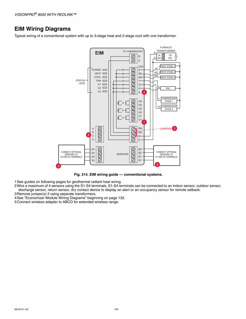
VISIONPRO® 8000 WITH REDLINK™
68-0312—02 120
EIM Wiring DiagramsTypical wiring of a conventional system with up to 3-stage heat and 2-stage cool with one transformer.
Fig. 314. EIM wiring guide — conventional systems.
1See guides on following pages for geothermal radiant heat wiring.2Wire a maximum of 4 sensors using the S1-S4 terminals. S1-S4 terminals can be connected to an indoor sensor, outdoor sensor,
discharge sensor, return sensor, dry contact device to display an alert or an occupancy sensor for remote setback.3Remove jumper(s) if using separate transformers.4See “Economizer Module Wiring Diagrams” beginning on page 132.5Connect wireless adapter to ABCD for extended wireless range.
HEAT STAGE 1
HEAT STAGE 2
HEAT STAGE 3
FAN
TO THERMOSTAT
STATUSLEDS
JUMPERS
SENSORS
CONV
FURNACE
R
C
WW2W3
G
Y2
Y
TRANSFORMER
120VAC
24VAC
COMPRESSORSTAGE 1
COMPRESSORSTAGE 2
POWERHEATCOOL
FANU1U2U3 A
CONNECT OPTIONALSENSORS TO
S1 AND S2 TERMINALS
S4
S4
S3
S3
CONNECT OPTIONALSENSORS TO
S3 AND S4 TERMINALS
AB
C
D
EIM
2
3
1
4
2
5
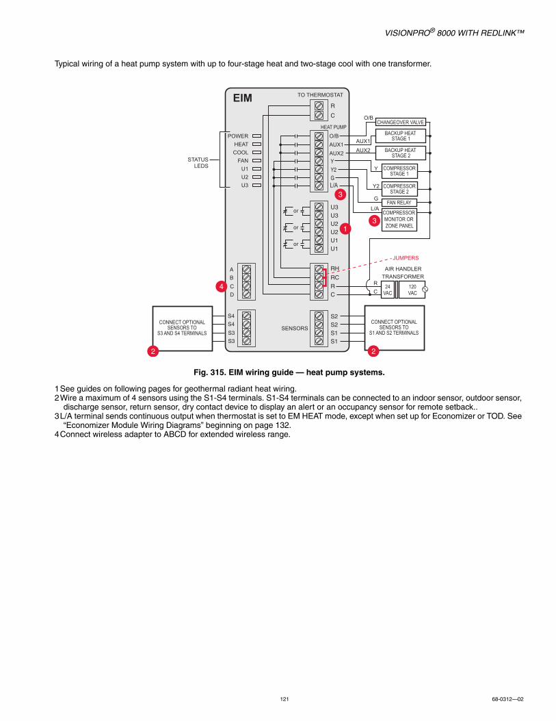
VISIONPRO® 8000 WITH REDLINK™
121 68-0312—02
Typical wiring of a heat pump system with up to four-stage heat and two-stage cool with one transformer.
Fig. 315. EIM wiring guide — heat pump systems.
1See guides on following pages for geothermal radiant heat wiring.2Wire a maximum of 4 sensors using the S1-S4 terminals. S1-S4 terminals can be connected to an indoor sensor, outdoor sensor,
discharge sensor, return sensor, dry contact device to display an alert or an occupancy sensor for remote setback..3L/A terminal sends continuous output when thermostat is set to EM HEAT mode, except when set up for Economizer or TOD. See
“Economizer Module Wiring Diagrams” beginning on page 132.4Connect wireless adapter to ABCD for extended wireless range.
CHANGEOVER VALVE
BACKUP HEAT STAGE 1
FAN RELAY
SENSORS
TO THERMOSTAT
HEAT PUMP
AIR HANDLERTRANSFORMER
120VAC
24VAC
COMPRESSORSTAGE 1
COMPRESSORSTAGE 2
O/BAUX1AUX2
O/B
BACKUP HEAT STAGE 2
COMPRESSOR MONITOR OR ZONE PANEL
RC
AUX1
AUX2
G
L/A
Y2
Y
POWERHEATCOOL
FANU1U2U3
STATUSLEDS
JUMPERS
L/A
EIM
CONNECT OPTIONALSENSORS TO
S1 AND S2 TERMINALS
S4
S4
S3
S3
CONNECT OPTIONALSENSORS TO
S3 AND S4 TERMINALS
A
B
C
D
22
31
3
4

VISIONPRO® 8000 WITH REDLINK™
68-0312—02 122
Typical wiring for geothermal radiant heat, geothermal forced-air, and backup heat with one transformer.
Fig. 316. EIM wiring guide — geothermal radiant heat.
1U1, U2 or U3 terminals must be used for geothermal radiant heat (ISU 201). Thermostat allows 2 stages of radiant heat—geo-thermal (stage 1) and boiler (stage 2).
2“U” terminals are normally open dry contacts when set up for geothermal radiant heat. You must install a field jumper if radiant heat is powered by system transformer. Do NOT install a field jumper if radiant heat has its own transformer.
3L/A terminal sends continuous output when thermostat is set to EM HEAT mode except when set up for Economizer or TOD. See “Economizer Module Wiring Diagrams” beginning on page 132.
4Wire a maximum of 4 sensors using the S1-S4 terminals. S1-S4 terminals can be connected to an indoor sensor, outdoor sensor, discharge sensor, return sensor, dry contact device to display an alert or an occupancy sensor for remote setback.
5Connect wireless adapter to ABCD for extended wireless range.
NOTE: For setup and operation, see “Geothermal Radiant Heat” beginning on page 78.
O/BAUX1AUX2
O/B
RC
AUX1
AUX2
G
L
Y2
Y
L/A
CHANGEOVER VALVE
BACKUP HEAT STAGE 1
FAN RELAY
120VAC
24VAC
COMPRESSORSTAGE 1
COMPRESSORSTAGE 2
BACKUP HEAT STAGE 2
COMPRESSOR MONITOROR ZONE PANEL
GEOTHERMAL RADIANTHEAT STAGE 1
AIR HANDLERTRANSFORMER
STATUSLEDS
JUMPERS
OPTIONALJUMPER
POWERHEATCOOL
FANU1U2U3
TO THERMOSTAT
HEAT PUMP
EIM
3
1
3
S4
S4
S3
S3
CONNECT OPTIONALSENSORS TO
S3 AND S4 TERMINALS
A
B
C
D
4
SENSORSCONNECT OPTIONAL
SENSORS TOS1 AND S2 TERMINALS
4
2
5
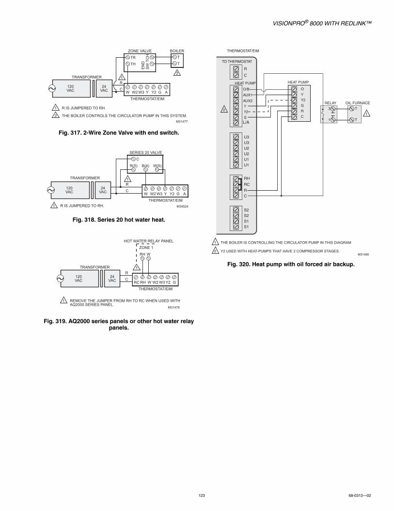
VISIONPRO® 8000 WITH REDLINK™
123 68-0312—02
Fig. 317. 2-Wire Zone Valve with end switch.
Fig. 318. Series 20 hot water heat.
Fig. 319. AQ2000 series panels or other hot water relay panels.
Fig. 320. Heat pump with oil forced air backup.
TRANSFORMER
THERMOSTAT/EIM
R IS JUMPERED TO RH.
THE BOILER CONTROLS THE CIRCULATOR PUMP IN THIS SYSTEM.
BOILER
W W2 W3 Y Y2 G A
M31477
24VAC
120VAC
T
T
R
C
ZONE VALVE
TR
TH
EN
DS
WTC
H
1
1
2
2
TRANSFORMER
R IS JUMPERED TO RH.1THERMOSTAT/EIM
W W2 W3 Y Y2 G A
M34524
24VAC
120VAC
R
C
SERIES 20 VALVE
C
R(5) B(4) W(6)
1
TRANSFORMER
REMOVE THE JUMPER FROM RH TO RC WHEN USED WITH AQ2000 SERIES PANEL.
1
THERMOSTAT/EIM
RC RH W W2 W3 Y2 G
M31479
24VAC
120VAC
R
C
HOT WATER RELAY PANEL
ZONE 1
RH W
1
O/B
AUX1
AUX2
O
Y
Y2
G
R
C
L/A
TO THERMOSTAT
THERMOSTAT/EIM
HEAT PUMP HEAT PUMP
M31480
1
RELAY
3
1
OIL FURNACE
T
T
THE BOILER IS CONTROLLING THE CIRCULATOR PUMP IN THIS DIAGRAM
Y2 USED WITH HEAT-PUMPS THAT HAVE 2 COMPRESSOR STAGES.
1
2
2
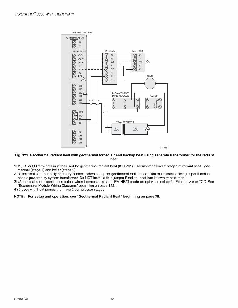
VISIONPRO® 8000 WITH REDLINK™
68-0312—02 124
Fig. 321. Geothermal radiant heat with geothermal forced air and backup heat using separate transformer for the radiant heat.
1U1, U2 or U3 terminals must be used for geothermal radiant heat (ISU 201). Thermostat allows 2 stages of radiant heat—geo-thermal (stage 1) and boiler (stage 2).
2“U” terminals are normally open dry contacts when set up for geothermal radiant heat. You must install a field jumper if radiant heat is powered by system transformer. Do NOT install a field jumper if radiant heat has its own transformer.
3L/A terminal sends continuous output when thermostat is set to EM HEAT mode except when set up for Economizer or TOD. See “Economizer Module Wiring Diagrams” beginning on page 132.
4Y2 used with heat pumps that have 2 compressor stages.
NOTE: For setup and operation, see “Geothermal Radiant Heat” beginning on page 78.
O/B
AUX1
AUX2
O
W1
W2
Y
Y2
G
R
C
O
Y
Y2
R
C
TRANSFORMER
24VAC
120VAC
L/A
TO THERMOSTAT
THERMOSTAT/EIM
HEAT PUMP FURNACE HEAT PUMP
M34525
RADIANT HEAT ZONE MODULE VALVE
PUMP
EN
DS
WTC
H
C
R
3
4
1
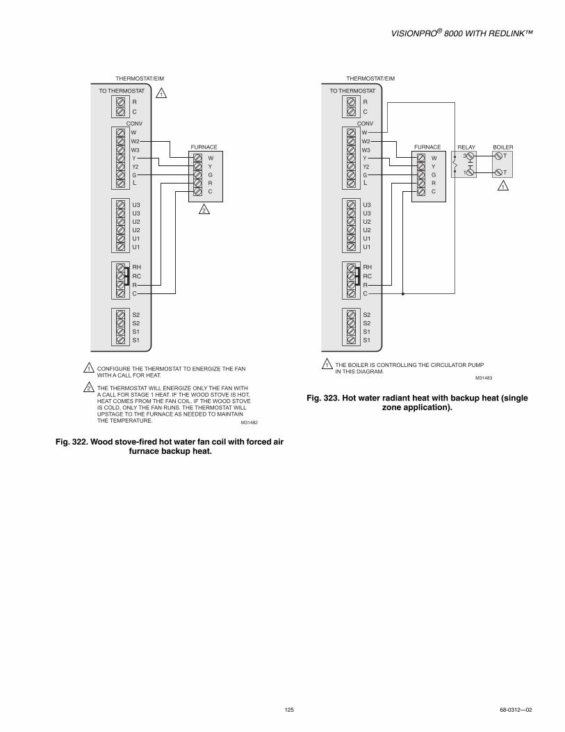
VISIONPRO® 8000 WITH REDLINK™
125 68-0312—02
Fig. 322. Wood stove-fired hot water fan coil with forced air furnace backup heat.
Fig. 323. Hot water radiant heat with backup heat (single zone application).
W
W2
W3
W
Y
G
R
C
CONFIGURE THE THERMOSTAT TO ENERGIZE THE FAN WITH A CALL FOR HEAT.
THE THERMOSTAT WILL ENERGIZE ONLY THE FAN WITH A CALL FOR STAGE 1 HEAT. IF THE WOOD STOVE IS HOT, HEAT COMES FROM THE FAN COIL. IF THE WOOD STOVE IS COLD, ONLY THE FAN RUNS. THE THERMOSTAT WILL UPSTAGE TO THE FURNACE AS NEEDED TO MAINTAIN THE TEMPERATURE.
L
TO THERMOSTAT
THERMOSTAT/EIM
CONV
FURNACE
M31482
1
2
1
2
W
W2
W3
W
Y
G
R
C
THE BOILER IS CONTROLLING THE CIRCULATOR PUMP IN THIS DIAGRAM.
L
TO THERMOSTAT
THERMOSTAT/EIM
CONV
FURNACE
M31483
1
1
BOILER
T
T
RELAY
3
1
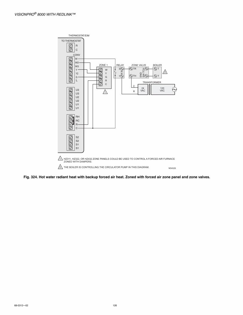
VISIONPRO® 8000 WITH REDLINK™
68-0312—02 126
Fig. 324. Hot water radiant heat with backup forced air heat. Zoned with forced air zone panel and zone valves.
TRANSFORMER
24VAC
120VAC
M34526
ZONE VALVETR
TH EN
DS
WTC
H
C
R
W
W2
W3
W
Y
G
R
C
HZ311, HZ322, OR HZ432 ZONE PANELS COULD BE USED TO CONTROL A FORCED AIR FURNACE ZONED WITH DAMPERS.
THE BOILER IS CONTROLLING THE CIRCULATOR PUMP IN THIS DIAGRAM.
L
TO THERMOSTAT
THERMOSTAT/EIM
CONV
ZONE 1
1
2
1
2
BOILER
T
T
RELAY
3
1

VISIONPRO® 8000 WITH REDLINK™
127 68-0312—02
Fig. 325. Hot water radiant heat with backup forced air heat. Zoned with forced air zone panel and hot water
panel.
Fig. 326. Hot water fan coil with forced air furnace backup heat.
M31485
HOT WATER RELAY PANEL
RH W
W
W2
W3
W
Y
G
R
C
HZ311, HZ322, OR HZ432 ZONE PANELS COULD BE USED TO CONTROL A FORCED AIR FURNACE ZONED WITH DAMPERS.
AN AQ2000 SERIES HOT WATER ZONE PANEL OR OTHER RELAY-BASED HOT WATER ZONE 3 PANEL COULD BE USED.
L
TO THERMOSTAT
THERMOSTAT/EIM
CONV
ZONE 1
ZONE 1
1
2
1
2
RELAY
3
1
W
W2
W3
W
Y
G
R
C
CONFIGURE THE THERMOSTAT TO ENERGIZE THE FAN WITH A CALL FOR HEAT.
THE BOILER IS CONTROLLING THE CIRCULATOR PUMP IN THIS DIAGRAM.
L
TO THERMOSTAT
THERMOSTAT/EIM
CONV
FURNACE
M31486
1
2
2
1
BOILER
T
T
RELAY
3
1

VISIONPRO® 8000 WITH REDLINK™
68-0312—02 128
Wood stove with heat pump and backup electric strips. (For applications in which the thermostat only needs to run the blower fan when stove is hot).
1Select Geothermal Radiant Heat at ISU 201. Connect Fan to U1, U2, or U3 as shown in the wiring diagram.2“U” terminals are normally open dry contacts when set up for geothermal radiant heat.3L/A terminal sends continuous output when thermostat is set to EM HEAT mode except when set up for Economizer or TOD. See
“Economizer Module Wiring Diagrams” beginning on page 132.4Y2 used with heat pumps that have 2 compressor stages.
NOTE: In Fig. , the thermostat will energize only the fan with a call for stage 1 heat. If the wood stove is hot, heat comes from the fan coil. If the wood stove is cold, only the fan runs. The thermostat will upstage to the heat pump and backup heat as needed to maintain the temperature.
O/B
AUX1
AUX2
O
W
Y
Y2
G
R
C
O
Y
Y2
R
C
L/A
TO THERMOSTAT
THERMOSTAT/EIM
HEAT PUMP AIR HANDLER HEAT PUMP
M31487
2
4
4
1
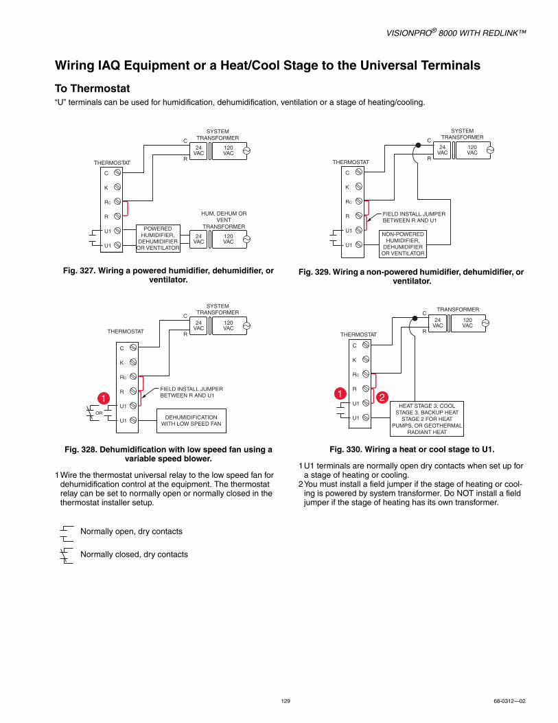
VISIONPRO® 8000 WITH REDLINK™
129 68-0312—02
Wiring IAQ Equipment or a Heat/Cool Stage to the Universal Terminals
To Thermostat“U” terminals can be used for humidification, dehumidification, ventilation or a stage of heating/cooling.
Fig. 327. Wiring a powered humidifier, dehumidifier, or ventilator.
Fig. 328. Dehumidification with low speed fan using a variable speed blower.
1Wire the thermostat universal relay to the low speed fan for dehumidification control at the equipment. The thermostat relay can be set to normally open or normally closed in the thermostat installer setup.
Fig. 329. Wiring a non-powered humidifier, dehumidifier, or ventilator.
Fig. 330. Wiring a heat or cool stage to U1.
1U1 terminals are normally open dry contacts when set up for a stage of heating or cooling.
2You must install a field jumper if the stage of heating or cool-ing is powered by system transformer. Do NOT install a field jumper if the stage of heating has its own transformer.
Normally open, dry contacts
Normally closed, dry contacts
C
K
RC
R
U1
U1
120VAC
24VAC
C
R
SYSTEMTRANSFORMER
120VAC
24VAC
HUM, DEHUM OR VENT
TRANSFORMER
THERMOSTAT
POWERED HUMIDIFIER,
DEHUMIDIFIER OR VENTILATOR
1
C
K
RC
R
U1
U1
120VAC
24VAC
C
R
SYSTEMTRANSFORMER
THERMOSTAT
DEHUMIDIFICATION WITH LOW SPEED FAN
FIELD INSTALL JUMPER BETWEEN R AND U1
OR
C
K
RC
R
U1
U1
120VAC
24VAC
C
R
SYSTEMTRANSFORMER
THERMOSTAT
NON-POWERED HUMIDIFIER,
DEHUMIDIFIER OR VENTILATOR
FIELD INSTALL JUMPER BETWEEN R AND U1
2
C
K
RC
R
U1
U1
120VAC
24VAC
C
R
TRANSFORMER
THERMOSTAT
HEAT STAGE 3, COOL STAGE 3, BACKUP HEAT
STAGE 2 FOR HEAT PUMPS, OR GEOTHERMAL
RADIANT HEAT
1

VISIONPRO® 8000 WITH REDLINK™
68-0312—02 130
Wiring IAQ Equipment or a Heat/Cool Stage to the Universal Terminals
To Equipment Interface Module“U” terminals can be used for humidification, dehumidification, ventilation or a stage of heating/cooling.
Fig. 331. Typical hookup of powered humidifier.
Fig. 332. Typical hookup of powered ventilation.
Fig. 333. Typical hookup of powered dehumidifier (whole house dehumidifer).
Fig. 334. Typical hookup of non-powered humidifier.
Fig. 335. Typical hookup of non-powered ventilation.
Fig. 336. Typical hookup of variable speed blower for dehumidification in low speed.
1Any combination of universal relays (U1, U2, U3) can be used. They are set in the thermostat installer setup.2Wire the universal EIM relay to the low speed fan for dehumidification control at the equipment. The EIM relay can be set to be
normally open or normally closed in the thermostat installer setup.
POWEREDHUMIDIFIER
RH
RC
R
C
U3
U3U2
U2
U1 U1
MCR32393A
24VAC
120VAC
24VAC
120VAC24
VAC
1
POWEREDVENTILATOR
RH
RC
R
C24
VAC
U3
U3U2
U2
U1 U1
MCR32396A
24VAC
120VAC
24VAC
120VAC
1
POWEREDDEHUMIDIFIER
RH
RC
R
C
U3
U3U2
U2
U1 U1
MCR32398A
24VAC
120VAC
24VAC
120VAC24
VAC
1
FIELD INSTALLED JUMPER BETWEEN R AND U1
RH
RC
R
C24 VAC
U3
U3U2
U2
U1 U1
NON POWEREDHUMIDFIER
24VAC
120VAC
1
FIELD INSTALLED JUMPER BETWEEN R AND U1
RH
RC
R
C24 VAC
U3
U3U2
U2
U1 U1
NON POWEREDVENTILATOR
24VAC
120VAC
1
FIELD INSTALLED JUMPER BETWEEN R AND U1
RH
RC
R
C24 VAC
U3
U3U2
U2
U1 U1
ORDEHUMIDIFICATION
WITH LOW SPEED FAN
24VAC
120VAC
1
2
Normally open, dry contacts
Normally closed, dry contacts
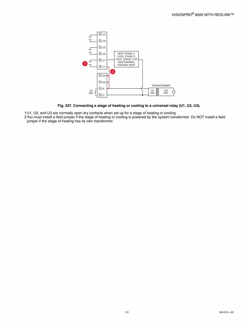
VISIONPRO® 8000 WITH REDLINK™
131 68-0312—02
Fig. 337. Connecting a stage of heating or cooling to a universal relay (U1, U2, U3).
1U1, U2, and U3 are normally open dry contacts when set up for a stage of heating or cooling.2You must install a field jumper if the stage of heating or cooling is powered by the system transformer. Do NOT install a field
jumper if the stage of heating has its own transformer.
1
2
U3
U3
U2
U2
U1
U1
120VAC
24VAC
24VAC
HEAT STAGE 3, COOL STAGE 3,
COOL STAGE 4 ORGEOTHERMAL RADIANT HEAT
RH
RC
R
C
TRANSFORMER

VISIONPRO® 8000 WITH REDLINK™
68-0312—02 132
Economizer Module Wiring DiagramsTypical wiring of a W7220 Economizer Module for a heat pump system, using a VisionPRO with RedLINK thermostat or Equipment Interface Module.
Fig. 338. Wiring a W7220 Economizer Module for a heat pump system.
Typical wiring of a W7220 Economizer Module for a conventional system, using a VisionPRO with RedLINK thermostat or Equipment Interface Module.
Fig. 339. Wiring a W7220 Economizer Module for a conventional system.
1“A” or “L/A” terminal must be configured for Economizer in the installer setup (ISU 222). These terminals are powered by the cool-ing transformer (Rc terminal).
2Terminal AUX 2 is present only on the Equipment Interface Module.3Connect the changeover valve from the roof top unit to the normally open contacts of an isolation relay to prevent feedback into
the economizer module during defrost. If this is not done when the system goes into defrost, it will change the economizer into cooling mode due to the feedback and open the outside damper while in heating mode.
120VAC
O/B Y1 Y2 AUX AUX 2 G
24VAC
AUX2-I
OCC
E-GND
AUX1-O
Y2-I
Y2-O
Y1-I
Y1-O
C
R
Rooftop Unit
Transformer
O/B L/A Y Y2 AUX AUX 2 G
Thermostat/EIMR
C
W7220 Economizer Module(See wiring guidelines provided with the product)
21
MCR34808
3
3 1
120VAC
Y1 Y2 W1 W2 G
24VAC
Rooftop Unit
Transformer
A Y Y2 W W2 G
Thermostat/EIMR
C
W7220 Economizer Module(See wiring guidelines provided with the product)
1
MCR34810
AUX2-I
OCC
E-GND
AUX1-O
Y2-I
Y2-O
Y1-I
Y1-O
C
R
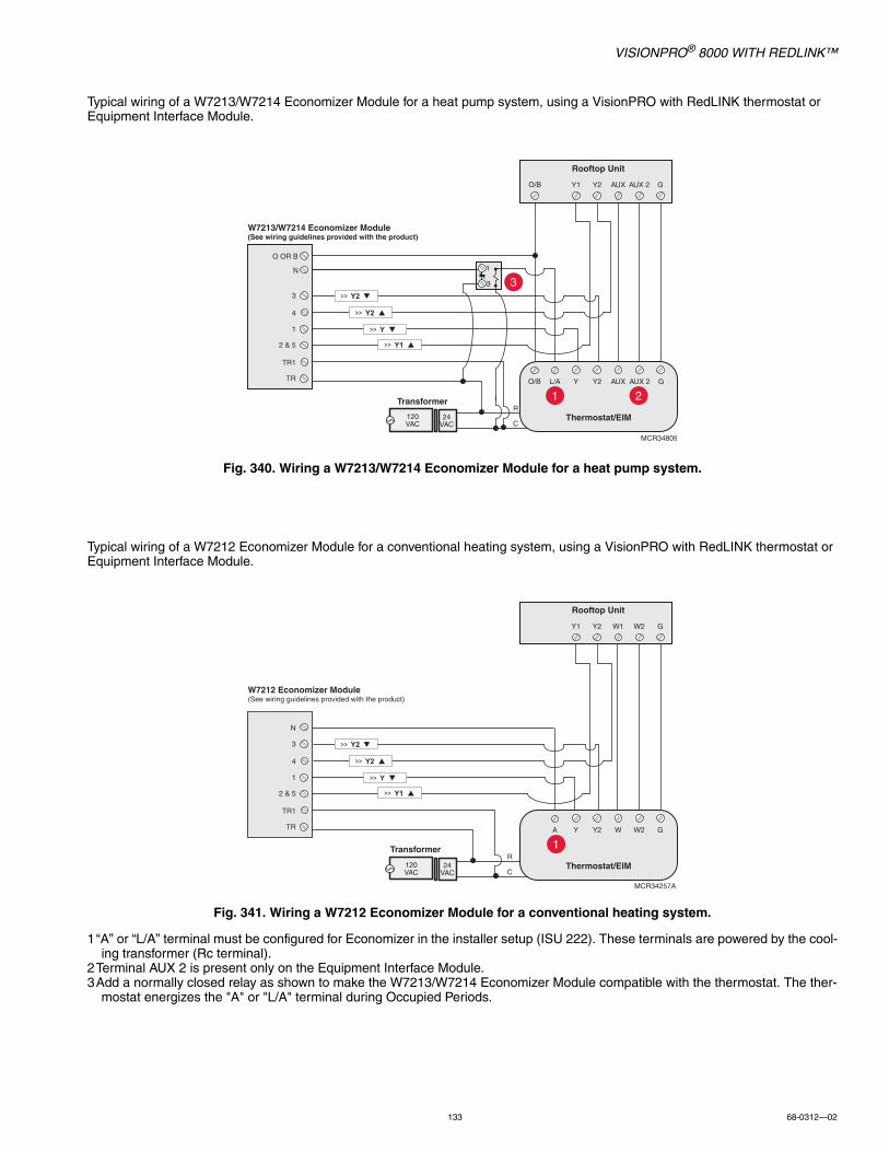
VISIONPRO® 8000 WITH REDLINK™
133 68-0312—02
Typical wiring of a W7213/W7214 Economizer Module for a heat pump system, using a VisionPRO with RedLINK thermostat or Equipment Interface Module.
Fig. 340. Wiring a W7213/W7214 Economizer Module for a heat pump system.
Typical wiring of a W7212 Economizer Module for a conventional heating system, using a VisionPRO with RedLINK thermostat or Equipment Interface Module.
Fig. 341. Wiring a W7212 Economizer Module for a conventional heating system.
1“A” or “L/A” terminal must be configured for Economizer in the installer setup (ISU 222). These terminals are powered by the cool-ing transformer (Rc terminal).
2Terminal AUX 2 is present only on the Equipment Interface Module.3Add a normally closed relay as shown to make the W7213/W7214 Economizer Module compatible with the thermostat. The ther-
mostat energizes the "A" or "L/A" terminal during Occupied Periods.
120VAC
Y1 Y2 AUX AUX 2 G
24VAC
O OR B
N
3
4
1
2 & 5
TR1
TR
Rooftop Unit
Transformer
L/A Y Y2 AUX AUX 2 G
Thermostat/EIMR
C
W7213/W7214 Economizer Module(See wiring guidelines provided with the product)
O/B
O/B
1
3
2
MCR34809
3
1
120VAC
Y1 Y2 W1 W2 G
24VAC
N
3
4
1
2 & 5
TR1
TR
Rooftop Unit
Transformer
A Y Y2 W W2 G
Thermostat/EIMR
C
W7212 Economizer Module(See wiring guidelines provided with the product)
1
MCR34257A
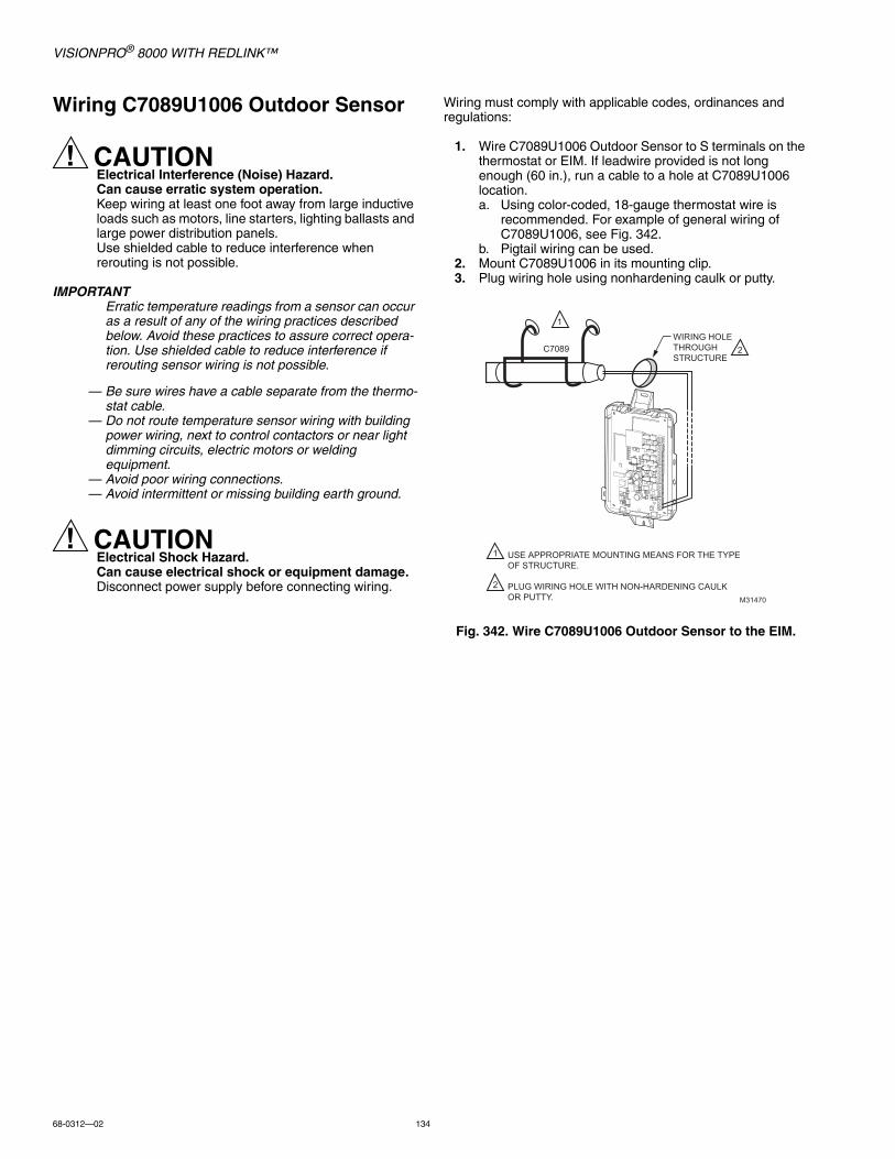
VISIONPRO® 8000 WITH REDLINK™
68-0312—02 134
Wiring C7089U1006 Outdoor Sensor
CAUTIONElectrical Interference (Noise) Hazard.Can cause erratic system operation. Keep wiring at least one foot away from large inductive loads such as motors, line starters, lighting ballasts and large power distribution panels.Use shielded cable to reduce interference when rerouting is not possible.
IMPORTANTErratic temperature readings from a sensor can occur as a result of any of the wiring practices described below. Avoid these practices to assure correct opera-tion. Use shielded cable to reduce interference if rerouting sensor wiring is not possible.
— Be sure wires have a cable separate from the thermo-stat cable.
— Do not route temperature sensor wiring with building power wiring, next to control contactors or near light dimming circuits, electric motors or weldingequipment.
— Avoid poor wiring connections.— Avoid intermittent or missing building earth ground.
CAUTIONElectrical Shock Hazard.Can cause electrical shock or equipment damage.Disconnect power supply before connecting wiring.
Wiring must comply with applicable codes, ordinances and regulations:
1. Wire C7089U1006 Outdoor Sensor to S terminals on the thermostat or EIM. If leadwire provided is not long enough (60 in.), run a cable to a hole at C7089U1006 location.a. Using color-coded, 18-gauge thermostat wire is
recommended. For example of general wiring of C7089U1006, see Fig. 342.
b. Pigtail wiring can be used.2. Mount C7089U1006 in its mounting clip.3. Plug wiring hole using nonhardening caulk or putty.
Fig. 342. Wire C7089U1006 Outdoor Sensor to the EIM.
1
2
2
1
USE APPROPRIATE MOUNTING MEANS FOR THE TYPE OF STRUCTURE.
PLUG WIRING HOLE WITH NON-HARDENING CAULK OR PUTTY.
C7089WIRING HOLE THROUGH STRUCTURE
M31470

VISIONPRO® 8000 WITH REDLINK™
135 68-0312—02
Wiring guide — Wired Indoor Sensors
CAUTIONElectrical Interference (Noise) Hazard.Can cause erratic system operation. Keep wiring at least one foot away from large inductive loads such as motors, line starters, lighting ballasts and large power distribution panels.Use shielded cable to reduce interference when rerouting is not possible.
IMPORTANTErratic temperature readings from a sensor can occur as a result of any of the wiring practices described below. Avoid these practices to assure correct opera-tion. Use shielded cable to reduce interference if rerouting sensor wiring is not possible.
— Be sure wires have a cable separate from the thermo-stat cable.
— Do not route temperature sensor wiring with building power wiring, next to control contactors or near light dimming circuits, electric motors or weldingequipment.
— Avoid poor wiring connections.— Avoid intermittent or missing building earth ground.
CAUTIONElectrical Shock Hazard.Can cause electrical shock or equipment damage.Disconnect power supply before connecting wiring.
Use the S1, S2, S3 or S4 terminals for wired sensors.
Wiring 4 C7189U1005 sensors (10k ohm) for temperature averaging network. Select 10K in the Installer Setup (ISU 503) when using C7189U1005 sensor(s).
Fig. 343. Wiring 4 C7189U sensors.
Wiring 2 TR21 sensors (20k ohm) and 1 TR21-A sensor (10k ohm) for temperature averaging network. Select 20K in the Installer Setup (ISU 503) when using 2 TR21 sensors and 1 TR21-A sensor.
Fig. 344. Wiring 2 TR21 sensors and 1 TR21-A sensor.
Wiring 4 TR21 sensors (20k ohm). Select 20K in the Installer Setup (ISU 503) when using TR21 sensor(s).
Fig. 345. Wiring 4 TR21 sensors.
Wiring 2 TR21-A sensors (10k ohm) for temperature averaging network. Select 20K in the Installer Setup (ISU 503) when using 2 TR21-A sensors in series. Note: The TR21-A sensor must be used in combination with TR21 or TR21-A sensor.
Fig. 346. Wiring 2 TR21-A sensors.
C7189 C7189
C7189 C7189
EIM
M31472
THE NUMBER OF C7189U SENSORS MUST BE A SQUARE NUMBER (1, 4, 9, 16, ETC.)
1
1
M31473
EIMTR21 A
T3
T4
TR21 TR21
M31474
EIM
TR21 TR21
TR21 TR21
M31475
EIMTR21 A
T3
T4
TR21 A
T3
T4

VISIONPRO® 8000 WITH REDLINK™
68-0312—02 136
ZONINGThe following diagrams show the wiring for zoning with different IAQ equipment.
Fig. 347. RedLINK VisionPRO thermostats with an HZ432 zone panel and no IAQ control.
C RC RC RC R
RHRC
W1/EW2W3Y1Y2GOB
DS/BK
M34527
TRANSFORMER
RC
M1M4M6
RC
W1/EW2W3Y1Y2G
O/BL
DATSDATS
OTOT
AZ1AZ2
ZO
NE
4D
AM
PE
RT
HE
RM
OS
TAT
EQ
UIP
ME
NT
PO
WE
RS
EN
SO
RS
AC
CE
SS
OR
IES
C7735A1000DATS
ABCD
THM4000R1000
WIR
EL
ES
S
C
R
W
W2
Y
Y2
G
FURNACE
4
4
1
5
5 2
2
2
RC
CON E T
POW R
THM4000R
CON E TE
W RE ESS S TUP
1
3
3
1
VISIONPRO THERMOSTATS CAN BE POWERED BY ANY TRANSFORMER. IN THIS EXAMPLE THEY ARE POWERED BY THE SAME TRANSFORMER THAT POWERS THE HZ432.
THERE CAN BE UP TO 4 VISIONPRO THERMOSTATS USED WITH A SINGLE THM4000R WIRELESS ADAPTER AND HZ432 ZONE PANEL. THE THM4000R CANNOT BE USED IF THERE ARE MORE THAN 4 ZONES IN THE SYSTEM.
RH/RC JUMPER INSTALLED WHEN SINGLE HEAT/COOL TRANSFORMER IS USED.
DOTTED LINES APPLY ONLY TO MULTI-STAGE EQUIPMENT. SEE HZ432 INSTALLATION INSTRUCTIONS FOR HEAT PUMP WIRING.
A THM4000R CANNOT BE USED WITH THE VISIONPRO THERMOSTAT IF THE THERMOSTAT IS CONTROLLING HUMIDIFICATION, DEHUMIDIFICATION, OR VENTILATION.

VISIONPRO® 8000 WITH REDLINK™
137 68-0312—02
Zoning and Humidification
Fig. 348. RedLINK VisionPRO thermostat controlling one zone with an HZ432 zone panel and a TrueSTEAM humidifier.
Setting up Humidification Control on RedLINK VisionPRO ThermostatsSelect the terminals wired to the humidifier at ISU 803 (U1, U2, U3). In Fig. 348, the humidifier is wired to U1. To humidify in all zones, set ISU 807 Humidifier Control to “Hum Controls Fan.” Call Honeywell zoning at 1-800-828-8367 if you need assistance with the zoning controls.
24 V24 VHUMHUMCGTRRTGFEXT
W
W2
W3
L
CONV
RHRC
W1/EW2W3Y1Y2GOB
DS/BK
M34528
M1M4M6
RC
W1/EW2W3Y1Y2G
O/BL
DATSDATS
OTOT
AZ1AZ2
ZO
NE
4D
AM
PE
RT
HE
RM
OS
TAT
EQ
UIP
ME
NT
PO
WE
RS
EN
SO
RS
AC
CE
SS
OR
IES
RC
C7735A1000DATS
ABCDW
IRE
LE
SS
C
R
W
W2
Y
Y2
G
FURNACEAFS5
4
1
5
2
2
R
C
1
4
3
3
1
A DEDICATED TRANSFORMER SHOULD POWER THE HZ432. IF A DIFFERENT TRANSFORMER IS USED TO POWER THE EIM, THE JUMPER FROM R TO RH NEEDS TO BE REMOVED AND THE RH AND RC FROM EIM GETS WIRED TO R ON THE ZONE THAT THE EIM IS WIRED TO.
THE VISIONPRO THERMOSTAT CAN BE POWERED FROM ANY TRANSFORMER. IN THIS EXAMPLE IT IS WIRED BACK TO THE EIM.
DOTTED LINES ONLY APPLY TO MULTI-STAGE EQUIPMENT. SEE HZ432 INSTALLATION INSTRUCTIONS FOR HEAT PUMP WIRING.
RH/RC JUMPER INSTALLED WHEN SINGLE HEAT/COOL TRANSFORMER IS USED.
TO SIMPLIFY THE DIAGRAM, THE VISIONPRO IS CONTROLLING ZONE 4 BECAUSE IT IS LOCATED ON THE SAME SIDE OF THE EQUIPMENT WIRING ON THE PANEL. THE VISIONPRO COULD BE WIRED TO ANY ZONE ON THE HZ432 AND IS MOST COMMONLY WIRED TO ZONE 1.

VISIONPRO® 8000 WITH REDLINK™
68-0312—02 138
Zoning and Ventilation
Fig. 349. RedLINK VisionPRO thermostat with an HZ432 zone panel and a ventilator.
Setting up Ventilation Control on RedLINK VisionPRO ThermostatsSelect the terminals wired to the ventilator at ISU 1002 (U1, U2, U3). In Fig. 349, the ventilator is wired to U1. To ventilate in all zones, set ISU 1006 Vent Fan Control to “Equip Controls Fan.”
TrueDRY dehumidifier with Zoning
Fig. 350. RedLINK VisionPRO thermostat with an HZ432 zone panel and a TrueDRY dehumidifier.
Setting up Dehumidification Control on RedLINK VisionPRO ThermostatsSelect the terminals wired to the dehumidifier at ISU 904 (U1, U2, U3). In Fig. 350, the dehumidifier is wired to U1. To dehumidify in all zones, set ISU 913 Dehum Fan Control to “Equip Controls Fan.”
RHRC
W1/EW2W3Y1Y2GOB
DS/BK
M34529
EQ
UIP
ME
NT
C
R
W
Y
G
FURNACE
TrueZONE PANEL
VisionPRO EIM
ERV/HRV
INTERLOCK B G R
AUX W B G R
2
2
1
1
SELECT THE TERMINALS WIRED TO THE VENTILATOR AT ISU 1002 (U1, U2, U3). TO VENTILATE IN ALL ZONES, SET ISU 1006 VENT FAN CONTROL TO EQUIP CONTROLS FAN.
FOR ALL ZONE PANEL WIRING NOT SHOWN IN THIS DIAGRAM, SEE OTHER ZONING DIAGRAMS OR ZONE PANEL INSTALLATION INSTRUCTIONS.
RHRC
W1/EW2W3Y1Y2GOB
DS/BK
EQ
UIP
ME
NT
C
R
W
Y
G
FURNACE
TrueZONE PANELVisionPRO
EIM
TrueDRY DEHUMIDIFIERDHUM R FAN C GT Rf Gf
2
2
1
1
SELECT THE TERMINALS WIRED TO THE VENTILATOR AT ISU 904 (U1, U2, U3). TO VENTILATE IN ALL ZONES, SET ISU 913 DEHUM FAN CONTROL TO EQUIP CONTROLS FAN.
FOR ALL ZONE PANEL WIRING NOT SHOWN IN THIS DIAGRAM, SEE OTHER ZONING DIAGRAMS OR ZONE PANEL INSTALLATION INSTRUCTIONS. M34530
VISIONPRO® 8000 WITH REDLINK™
139 68-0312—02
Zoning FAQsQ: How does the RedLINK VisionPRO thermostat control a humidifier in zoned systems?A: If ISU 807 Humidifier Control is set to Tstat Controls Fan, then the zone panel will close the dampers for the other zones with a
call for humidification. If ISU 807 Humidifier Control is set to Hum Controls Fan, then all dampers will be open with a call for humidification (unless another zone is calling for heat, cool or fan at that time). See Fig. 348.
Q: How does the RedLINK VisionPRO thermostat control a ventilator in zoned systems?A: If ISU 1006 Vent Fan Control is set to Tstat Controls Fan, then the zone panel will close the dampers for the other zones with a
call for ventilation. If ISU 1006 Vent Fan Control is set to Equip Controls Fan, then all dampers will be open with a call for ventilation (unless another zone is calling for heat, cool or fan at that time).See Fig. 349.
Q: How does the RedLINK VisionPRO thermostat control a dehumidifier in zoned systems?A: If ISU 913 Dehum Fan Control is set to Tstat Controls Fan, then the zone panel will close the dampers for the other zones with
a call for dehumidification.If ISU 913 Dehum Fan Control is set to Equip Controls Fan, then all dampers will be open with a call for dehumidification (unless another zone is calling for heat, cool or fan at that time). See Fig. 350.
Q: Will the RedLINK VisionPRO thermostat work with a zone panel?A: It depends on the zone panel:
• HZ322 or HZ432 (without an add-a-zone): If you have an HZ322 or HZ432 on a 2-4 zone system and you are not going to control a humidifier, dehumidifier, or ventilator with the thermostat, you can use a THM4000R1000 wireless adapter with the zone panel and connect the RedLINK VisionPRO thermostat as one of the zones. A single THM4000R1000 wireless adapter allows you to connect up to three RedLINK VisionPRO thermostats with an HZ322 or up to four RedLINK VisionPRO thermostats with an HZ432.
• HZ432 (with a TAZ-4 add-a-zone): You cannot use a wireless adapter when a TAZ-4 is used. Each RedLINK VisionPRO thermostat used would need a separate THM5421R Equipment Interface Module or you can wire the RedLINK VisionPRO directly to the zone panel. The Equipment Interface Module would wire to the zone it is controlling on the HZ432 or TAZ-4.
• Zone panel with no master or slave: As long as all zones on the zone panel are wired the same and they use typical terminals with an R and C plus Y, G, etc, the RedLINK VisionPRO thermostat should work. Each RedLINK VisionPRO thermostat used would need a separate THM5421R Equipment Interface Module or you can wire the RedLINK VisionPRO directly to the zone panel. The Equipment Interface Module would wire to the zone it is controlling on the zone panel.
• Master zone: A master uses separate O and B wires. The RedLINK VisionPRO thermostat cannot be used as a master thermostat.
Q: Can I use the remote indoor sensors with the RedLINK VisionPRO thermostats if I have zoning?A: It depends. The RedLINK VisionPRO thermostats can only control 1 zone, even if it is used with multiple sensors. The
RedLINK VisionPRO thermostat cannot be used with a remote sensor if it is used with a THM4000R adapter. The RedLINK VisionPRO thermostat can be used with a remote sensor if it is used with a THM5421R Equipment Interface Module or if the thermostat is wired directly to the panel.
Q: Can I use a telephone access module with the RedLINK VisionPRO thermostat?A: No. The telephone access module only works with the TH9421C or TH5320C communicating thermostats and the EIM or
zone panel used with those controls. See the Gateway section for information on using RedLINK VisionPRO thermostats with a THM6000R Gateway for Internet access.
VISIONPRO® 8000 WITH REDLINK™
Automation and Control SolutionsHoneywell International Inc.
1985 Douglas Drive North
Golden Valley, MN 55422
customer.honeywell.com
® U S. Registered Trademark© 2013 Honeywell International Inc.68-0312—02 M.S. Rev. 04-13Printed in United States
TROUBLESHOOTING
REGULATORY INFORMATIONFCC Compliance Statement (Part 15.19) (USA only)This device complies with Part 15 of the FCC Rules. Operation is subject to the following two conditions:
1. This device may not cause harmful interference, and2. This device must accept any interference received,
including interference that may cause undesired opera-tion.
FCC Warning (Part 15.21) (USA only)Changes or modifications not expressly approved by the party responsible for compliance could void the user’s authority to operate the equipment.
FCC Interference Statement (Part 15.105 (b)) (USA only)This equipment has been tested and found to comply with the limits for a Class B digital device, pursuant to Part 15 of the FCC Rules. These limits are designed to provide reasonable protection against harmful interference in a residential installation. This equipment generates uses and can radiate radio frequency energy and, if not installed and used in accordance with the instructions, may cause harmful interference to radio communications. However, there is no guarantee that interference will not occur in a particular installation. If this equipment does cause harmful interference to radio or television reception, which can be determined by turning the equipment off and on, the user is encouraged to try to correct the interference by one of the following measures:
• Reorient or relocate the receiving antenna.• Increase the separation between the equipment and
receiver.
• Connect the equipment into an outlet on a circuit different from that to which the receiver is connected.
• Consult the dealer or an experienced radio/TV technician for help.
Equipment interface module, thermostats and outdoor sensorTo comply with FCC and Industry Canada RF exposure limits for general population/ uncontrolled exposure, the antenna(s) used for these transmitters must be installed to provide a separation distance of at least 20 cm from all persons and must not be co-located or operating in conjunction with any other antenna or transmitter.
Portable Comfort ControlThis portable transmitter with its antenna complies with FCC and Industry Canada RF exposure limits for general population/uncontrolled exposure. This device must not be co-located or operating in conjunction with any other antenna or transmitter.
Section 7.1.2 of RSS-GENUnder Industry Canada regulations, this radio transmitter may only operate using an antenna of type and maximum (or lesser) gain approved for the transmitter by Industry Canada. To reduce potential radio interference to other users, the antenna type and its gain should be so chosen that the equivalent isotropically radiated power (e.i.r.p.) is not more than that necessary for successful communication.
Section 7.1.3 of RSS-GENOperation is subject to the following two conditions:
1. this device may not cause interference, and2. this device must accept any interference, including inter-
ference that may cause undesired operation of the device.
Table 13. Troubleshooting.
Symptom Action
Screen is blank • Check circuit breaker and reset if necessary.• Make sure power switch at heating and cooling system is on.• Make sure furnace door is closed securely.• If thermostat is battery powered, make sure fresh AA alkaline batteries are installed correctly.
Screen is difficult to read
• Change screen brightness using Preferences menu.
Red light is on • If thermostat is in Emergency Heat mode, the red light is normal. It shows that the thermostat is in Emergency Heat mode.
• If thermostat is not in Emergency Heat mode, an alert is active. Check message on the thermostat screen.
Heating or cooling system does not respond
• Touch SYSTEM to set system to Heat. Make sure the temperature is set higher than the Inside temperature.• Touch SYSTEM to set system to Cool. Make sure the temperature is set lower than the Inside temperature.• Check circuit breaker and reset if necessary.• Make sure power switch at heating & cooling system is on.• Make sure furnace door is closed securely.• If “Wait” is displayed, the compressor protection timer is on. Wait 5 minutes for the system to restart safely,
without damaging the compressor.