vision sensor user manual
TRANSCRIPT


Page 2 Vision Sensor SBSI-EN, 8033104 - 1401N12.05.2014
Vision Sensor User manual
Copyright (English)
No part of this document may be reproduced, published or stored in information retrieval systems or
data bases in any manner whatsoever, nor may illustrations, drawings and the layout be copied without
prior written permission from Festo AG & Co. KG.
We accept no responsibility for printing errors and mistakes which occurred in drafting these
documentations. Subject to delivery and technical alterations.
First publication February 2014
Festo AG & Co. KG
D-73726 Esslingen
Internet: http://www.festo.com
E-Mail: [email protected]
Vision Sensor SBSI-EN, 8033104 - 1401N12.05.2014 Page 3
Vision Sensor User manual
Table of Contents
1 General Information and Safety 7
1.1 Safety notes 7
1.2 Components supplied 7
1.3 Requirements for use 7
2 Intended Use 8
2.1 Field of application 8
2.2 Functions overview 9
2.3 Sensor types 10
2.3.1 Object detection 10
2.3.2 Code Reader 10
2.4 Field of view / Depth of view 12
3 Installation 15
3.1 Mechanical Installation 15
3.1.1 Arrangement for dark-field illumination 15
3.1.2 Arrangement for bright-field illumination 16
3.1.3 Alignment for a vertical illumination 17
3.1.4 Assembly Vision Sensor - Mounting bracket SBAM-C6-CP 18
3.2 Electrical installation 18
3.2.1 Connection possibilities 19
3.2.1.1 LED Display 19
3.2.1.2 Focussing screw 20
3.2.1.3 24 V DC Connection 20
3.2.1.4 LAN Connection 20
3.2.1.5 Data Connection 20
3.2.1.6 Plug connections 21
3.2.1.7 Exemplary connection plan and software settings for the following setup: 22
3.2.1.8 Electrical connection supply voltage and shield 23
3.2.1.9 Electrical connection PNP / NPN 23
3.3 Network settings, Short reference 24
3.3.1 Basic settings for PC and Vision Sensor 24
3.3.2 Direct Connection - Setting the IP Address of the PC 25
3.3.3 Network Connection - Setting the IP address of the Vision Sensor 26
4 Vision Sensor – Operating- and configuration software 28
4.1 Vision Sensor – Operating- and configuration software - Overview 28
4.1.1 Structure of PC software 28
4.1.2 Context help 28
4.2 Vision Sensor – Operating- and configuration software – Short introduction 29
4.2.1 Vision Sensor, Short introduction, Starting the software 29
4.2.2 Vision Sensor Device Manager: Open sensors or sensor simulation / Passwords 29
4.2.3 Passwords 31
4.2.4 Password levels: 31
4.3 Vision Sensor Configuration Studio: Setting sensor, Job 33
4.3.1 Job Setup 34
4.3.2 Alignment settings 35
4.3.3 Detector settings 36
4.3.4 Output, I/O and data output 37
Page 4 Vision Sensor SBSI-EN, 8033104 - 1401N12.05.2014
Vision Sensor User manual
4.3.5 Result 39
4.3.6 Start sensor 40
4.4 Vision Sensor Visualisation Studio, display images and results 41
4.5 Vision Sensor – Operating- and configuration software – Vision Sensor Device Manager, all func-
tions 42
4.5.1 Active sensors 42
4.5.2 Sensors for simulation mode 44
4.5.3 Find / Add active sensor 44
4.5.4 Configuring a connected sensor 45
4.5.5 Display images and result data 45
4.5.6 Sensor's network settings 45
4.5.7 Update / Firmware update 46
4.5.8 User administration / Passwords 46
4.6 Vision Sensor – Operating- and configuration software – Vision Sensor Configuration Studio, all
functions 48
4.6.1 Jobs (Inspection tasks) 48
4.6.1.1 Creation, modification and administration of jobs 49
4.6.1.2 Loading and saving jobs and job sets 50
4.6.1.3 Parameters for image acquisition 51
4.6.1.4 Parameters for image transmission 52
4.6.1.5 Parameters Archiving 53
4.6.1.6 Filter for image improvement. 55
4.6.1.7 Parameters Cycle time 56
4.6.2 Alignment 57
4.6.2.1 Alignment Contour detection 57
4.6.3 Detectors 58
4.6.3.1 Creating and adjusting detectors 59
4.6.3.2 Selecting a suitable detector 60
4.6.3.3 Detector Pattern matching 61
4.6.3.4 Detector Contour 66
4.6.3.5 Contrast detector 71
4.6.3.6 Grey detector 74
4.6.3.7 Brightness detector 77
4.6.3.8 Barcode detector. 79
4.6.3.9 2D Code detector 86
4.6.4 Output of inspection results 94
4.6.4.1 I/O mapping 94
4.6.4.2 Functions of the programmable, digital inputs: 96
4.6.4.3 Output signals (Digital outputs / Logic) 99
4.6.4.4 Interfaces 100
4.6.4.5 Timing, Digital outputs 101
4.6.4.6 Telegram, Data output 107
4.6.5 Result 110
4.6.6 Start sensor 112
4.6.7 Further topics of Vision Sensor Configuration Studio 113
4.6.7.1 Trigger settings 113
4.6.7.2 Switching between online and offline mode 114
4.6.7.3 Simulation of jobs (offline mode) 114
4.6.7.4 Creating filmstrips 114
Vision Sensor SBSI-EN, 8033104 - 1401N12.05.2014 Page 5
Vision Sensor User manual
4.6.7.5 Image recorder 116
4.6.7.6 Displays in image window 118
4.6.7.7 Search and parameter zones 119
4.7 Vision Sensor – Operating- and configuration software – Vision Sensor Visualisation Studio, all
functions 120
4.7.1 Image display 121
4.7.2 Commands / Freeze image 122
4.7.2.1 Zoom 122
4.7.3 Image recorder 122
4.7.4 Archiving test results and images 124
4.7.5 Statistics 125
4.7.6 Result 125
4.7.7 Changing active job 126
4.7.8 Upload 128
5 Communication 129
5.1 Possibilities of image- / data transfer and archiving 129
5.1.1 Ethernet, Port 2005 / 2006 129
5.1.1.1 Ethernet example 1: Pure data output from Vision Sensor to PC / PLC 129
5.1.1.2 Ethernet example 2: commands (requests) from PC / PLC to Vision Sensor 135
5.1.2 RS422 140
5.1.2.1 RS422 example 1: Data output from Vision Sensor to PC / PLC, and commands
(requests) to the Vision Sensor 141
5.1.3 PC- Archiving (Vision Sensor Visualisation Studio) 150
5.1.3.1 Start/end archiving: 153
5.1.4 Archiving via ftp or smb 153
5.1.4.1 Example: Archiving via ftp 153
5.1.4.2 Example: Archiving via smb 155
5.1.5 Ram disk (on the sensor) 161
5.2 Backup 164
5.2.1 Backup creation 164
5.2.2 Exchange Vision Sensor 164
5.3 Job switch 165
5.3.1 Job switch via digital inputs 165
5.3.1.1 Job 1 or Job 2 165
5.3.1.2 Job 1… 31 via binary bit pattern 165
5.3.1.3 Job 1..n via pulses 166
5.3.2 Job switch via Ethernet 166
5.3.3 Job switch via Serial 166
5.3.4 Job switch via Vision Sensor Visualisation Studio 167
5.4 Network connection 168
5.4.1 Installation of Vision Sensor into a network / gateway 168
5.4.2 Proceeding/Troubleshooting - Direct Connection 169
5.4.3 Proceeding/Troubleshooting - Network Connection 170
5.4.4 Used Ethernet- Ports 171
5.4.5 Access to the Vision Sensor via network 171
5.4.6 Access to the Vision Sensor via Internet / World Wide Web 173
5.5 Rescue 175
6 Image settings and accessories 177

Page 6 Vision Sensor SBSI-EN, 8033104 - 1401N12.05.2014
Vision Sensor User manual
6.1 Good images 177
6.2 Environmental light, shrouding, IR- version 177
6.3 External illumination 177
6.4 The most important types of illumination are: Bright field, Dark field and Diffuse illumination. 179
6.4.1 Bright field illumination 179
6.4.2 Dark field illumination 180
6.4.3 Diffuse illumination (external only) 181
7 Technical Data 182
8 Type key 184
9 Addendum 185
9.1 Telegram, Data output 185
9.1.1 Serial Communication ASCII 185
9.1.2 Serial communication BINARY 197
9.1.3 EtherNet/IP Assembly Request 212
9.1.4 EtherNet/IP Assembly Response 212
9.2 Starting Vision Sensor Visualisation Studio or Vision Sensor Configuration Studio via Autostart 214
9.3 Care and maintainance 214
9.3.1 Cleaning 214
9.3.2 Transport, packaging, storage 214
9.3.3 Waste disposal 215
9.3.4 Softreset 215
9.3.5 Sensor Firmware Update Vision Sensor 215

Vision Sensor SBSI-EN, 8033104 - 1401N12.05.2014 Page 7
Vision Sensor User manual
1 General Information and Safety
1.1 Safety notes
Before starting the Vision Sensor, read these instructions carefully, ensure that you have understood
them and comply with them at all times.
The Vision Sensor should only be connected by a qualified electrician.
Do not tamper with or make alterations on the unit!
The Vision Sensor is not a safety-critical component and its use is prohibited under conditions where the
safety of persons may depend on its function.
The IP address set for the Vision Sensor should be marked on the enclosed label. After installation, stick
the label on the sensor in a clearly visible position.
The IP address of the Vision Sensor must be used once only in any network.
For Use with any Listed (CYJV) cable assembly.
1.2 Components supplied
l Vision Sensor including integrated illumination.
l CD-ROM with Computer software and Operating instructions.
l Operating instructions, mounting clamp, Allen key, screwdriver, and protective cap for Ethernet plug.
1.3 Requirements for use
Configuration of the Vision Sensor requires a standard PC/Notebook (at least Pentium 4, 1GHz and 512
MB RAM, with Microsoft Windows XP SP3, Vista or Windows 7) with network connection or a network
with TCP-IP protocol. We recommend a Pentium 4 Dual Core > 2GHz and 1GB RAM, for Windows
Vista or Windows 7. We recommend a screen resolution of min. 1024 x 768 pixels. A basic knowledge of
computers is also required. The Vision Sensor is supplied with the IP address 192.168.100.100 and a sub-
net mask 255.255.255.0. The Vision Sensor is operated independently of a PC or PLC. A PC/notebook is
only necessary for configuration of the Vision Sensor.
Attention must be paid to sufficient and constant object illumination to ensure reproducible results and
avoid malfunction.
Reflections or varying incident light may affect detection results. If necessary, use an external light source
and/or light-screening / shrouding devices to exclude incident light
Page 8 Vision Sensor SBSI-EN, 8033104 - 1401N12.05.2014
Vision Sensor User manual
2 Intended Use
2.1 Field of application
The Vision Sensor is an optical sensor and uses several evaluation methods according to the version:
pattern recognition, contrast detection, grey level, contour detection, barcode or Data Matrix code read-
ing. The product is designed for industrial use only. In residential areas possibly additional measures for
noise suppression must be done.
Object:
The Vision Sensor precisely detects faulty parts, parts in the wrong place, at the wrong angle or in the
wrong order or a combination of all of these. A total of five detectors are available for inspection tasks
and interpretation: pattern recognition, contour detection, brightness, grey level and contrast detection.
The Vision Sensor also offers alignment: it is thus now also possible to reliably detect those features
which do not appear with repeated accuracy in the taught position. All interpretation is carried out rel-
ative to the actual position and angle of the part without having to define an independent characteristic for
each possible position. This high capacity tool also enables you to solve demanding pick and place applic-
ations.
Code Reader:
Identification of products, components or packaging from printed or directly marked – punched or laser-
etched – codes is common practice in many sectors of industry today. The Vision Code Reader imme-
diately detects which part is in front of it: it can easily read numerous types of barcodes as well as printed
and directly marked data matrix codes according to ECC 200 standard, and this on any base (metal, plastic,
paper, glass). The sensor can even routinely decipher askew or warped codes or codes on convex, reflect-
ive or transparent surfaces. The Vision Code Reader assesses the quality of your printed or directly
marked data matrix codes using standardised ISO and AIM quality parameters. This enables you to intro-
duce early correctional measures and thus avoid rejects due to illegible codes.
The Vision Sensor range is an economic alternative to conventional image processing systems.

Vision Sensor SBSI-EN, 8033104 - 1401N12.05.2014 Page 9
Vision Sensor User manual
2.2 Functions overview
Characteristics Vision Sensor Object / Code Reader
FunctionObject
Std.
Code
Reader
Std.
Frames per second 50 50
Number of Jobs 8 8
Alignment Contour only
Number of detectors 32 2
- Pattern matching
(X-, Y- translation)X
- Contour matching
(X-, Y- translation and rotation)X
- Grey level X
- Contrast X
- Brightness X
- Data code X
- Barcode X
4 digital outputs, 2 inputs, PNP or NPN X X
Free definable digital In- / Outputs, PNP or NPN 2 2
Free shape of ROI contour only
Timeout, specified time response X X
Variable resolutions X X
Illumination quadrant controlled X X
Image recorder X X
Ethernet interface X X
RS422 / RS232 interface X
EtherNet/IP interface X X
Sensor monitoring by Viewer, Job-Upload X X
R3 integrated 6 / 12 X / X X / X
Page 10 Vision Sensor SBSI-EN, 8033104 - 1401N12.05.2014
Vision Sensor User manual
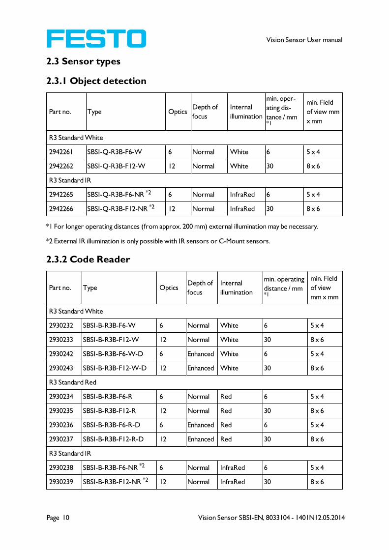
2.3 Sensor types
2.3.1 Object detection
Part no. Type OpticsDepth of
focus
Internal
illumination
min. oper-
ating dis-
tance / mm*1
min. Field
of view mm
x mm
R3 Standard White
2942261 SBSI-Q-R3B-F6-W 6 Normal White 6 5 x 4
2942262 SBSI-Q-R3B-F12-W 12 Normal White 30 8 x 6
R3 Standard IR
2942265 SBSI-Q-R3B-F6-NR *2 6 Normal InfraRed 6 5 x 4
2942266 SBSI-Q-R3B-F12-NR *2 12 Normal InfraRed 30 8 x 6
*1 For longer operating distances (from approx. 200 mm) external illumination may be necessary.
*2 External IR illumination is only possible with IR sensors or C-Mount sensors.
2.3.2 Code Reader
Part no. Type OpticsDepth of
focus
Internal
illumination
min. operating
distance / mm*1
min. Field
of view
mm x mm
R3 Standard White
2930232 SBSI-B-R3B-F6-W 6 Normal White 6 5 x 4
2930233 SBSI-B-R3B-F12-W 12 Normal White 30 8 x 6
2930242 SBSI-B-R3B-F6-W-D 6 Enhanced White 6 5 x 4
2930243 SBSI-B-R3B-F12-W-D 12 Enhanced White 30 8 x 6
R3 Standard Red
2930234 SBSI-B-R3B-F6-R 6 Normal Red 6 5 x 4
2930235 SBSI-B-R3B-F12-R 12 Normal Red 30 8 x 6
2930236 SBSI-B-R3B-F6-R-D 6 Enhanced Red 6 5 x 4
2930237 SBSI-B-R3B-F12-R-D 12 Enhanced Red 30 8 x 6
R3 Standard IR
2930238 SBSI-B-R3B-F6-NR *2 6 Normal InfraRed 6 5 x 4
2930239 SBSI-B-R3B-F12-NR *2 12 Normal InfraRed 30 8 x 6
Vision Sensor SBSI-EN, 8033104 - 1401N12.05.2014 Page 11
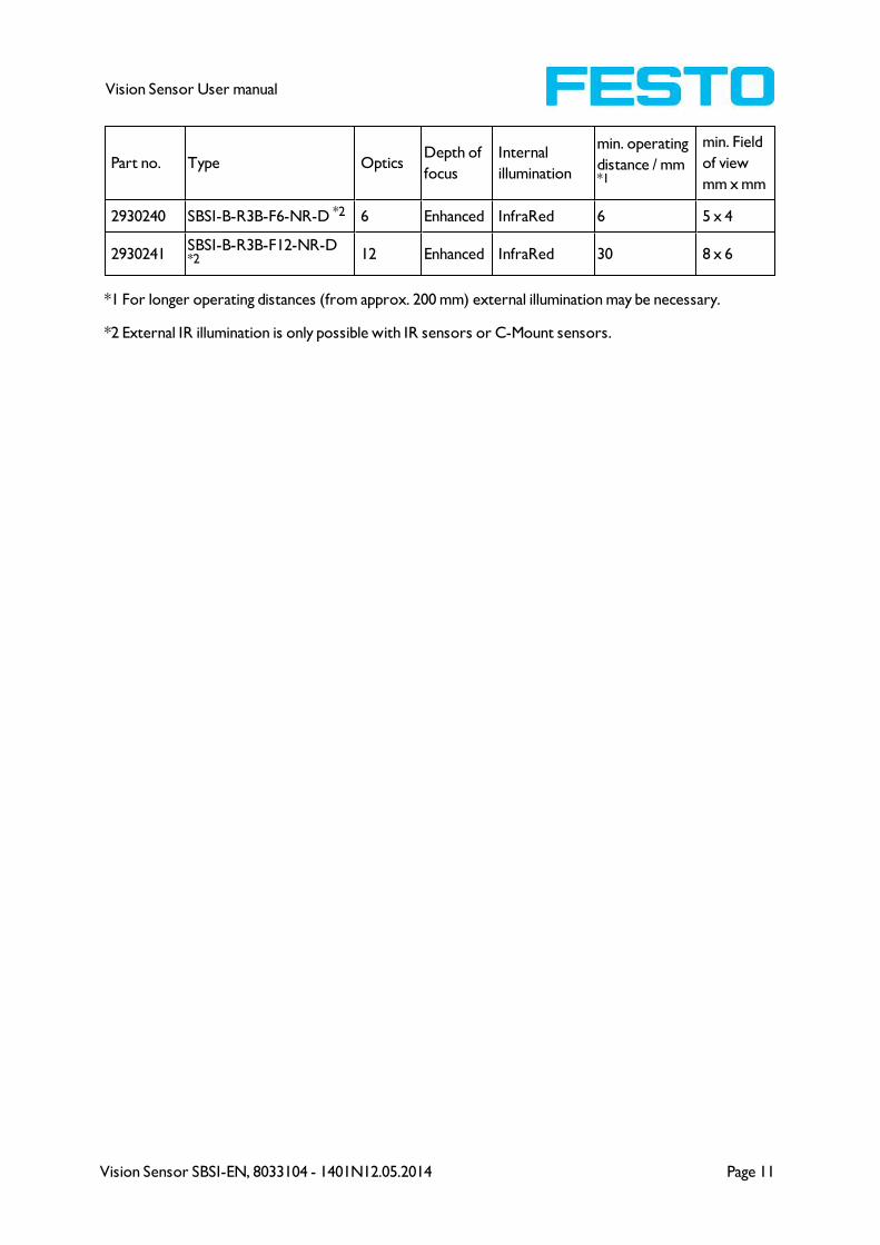
Vision Sensor User manual
Part no. Type OpticsDepth of
focus
Internal
illumination
min. operating
distance / mm*1
min. Field
of view
mm x mm
2930240 SBSI-B-R3B-F6-NR-D *2 6 Enhanced InfraRed 6 5 x 4
2930241SBSI-B-R3B-F12-NR-D*2 12 Enhanced InfraRed 30 8 x 6
*1 For longer operating distances (from approx. 200 mm) external illumination may be necessary.
*2 External IR illumination is only possible with IR sensors or C-Mount sensors.

Page 12 Vision Sensor SBSI-EN, 8033104 - 1401N12.05.2014
Vision Sensor User manual
2.4 Field of view / Depth of view
Field of view R3 6mm lens, internal
Fig. 1: Field of view R3 6mm lens, internal
Field of view R3 12mm lens, internal
Fig. 2: Field of view R3 12mm lens, internal
Vision Sensor SBSI-EN, 8033104 - 1401N12.05.2014 Page 13
Vision Sensor User manual
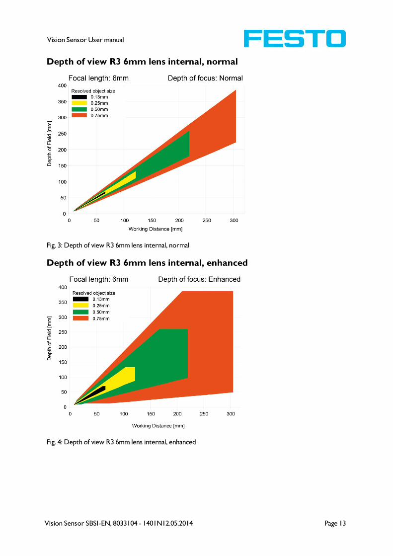
Depth of view R3 6mm lens internal, normal
Fig. 3: Depth of view R3 6mm lens internal, normal
Depth of view R3 6mm lens internal, enhanced
Fig. 4: Depth of view R3 6mm lens internal, enhanced
Page 14 Vision Sensor SBSI-EN, 8033104 - 1401N12.05.2014
Vision Sensor User manual
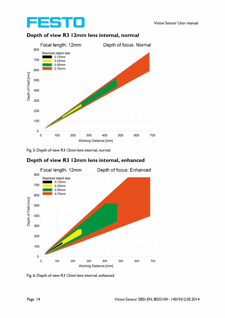
Depth of view R3 12mm lens internal, normal
Fig. 5: Depth of view R3 12mm lens internal, normal
Depth of view R3 12mm lens internal, enhanced
Fig. 6: Depth of view R3 12mm lens internal, enhanced
Vision Sensor SBSI-EN, 8033104 - 1401N12.05.2014 Page 15
Vision Sensor User manual
3 Installation
3.1 Mechanical Installation
To ensure maximum accuracy of detection, the Vision Sensor should be protected from vibration. Secure
the supply and I/O cables with cable binders to prevent crushing or slipping.
Select a position for the Vision Sensor in which interfering factors such as slight differences in the pos-
ition of the object or variations in illumination have little or no effect.
Screw the Vision Sensor onto the mounting clamp (supplied with the unit) and then onto a suitable object.
Use only the mounting clamp MK 45 (no. 543-11000) or the mounting hinge MG2A (no.543-11023).
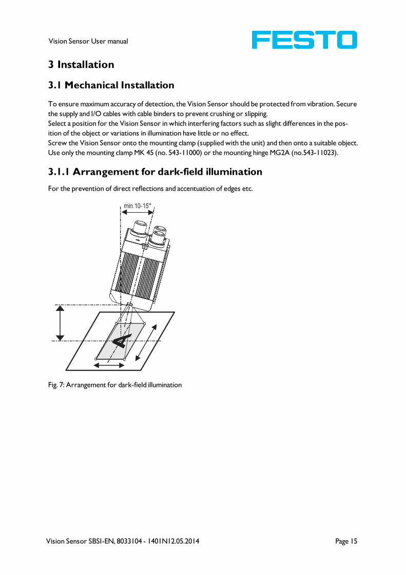
3.1.1 Arrangement for dark-field illumination
For the prevention of direct reflections and accentuation of edges etc.
Fig. 7: Arrangement for dark-field illumination

Page 16 Vision Sensor SBSI-EN, 8033104 - 1401N12.05.2014
Vision Sensor User manual
3.1.2 Arrangement for bright-field illumination
For transmitted light/measuring tasks or for the accentuation of highly-reflective objects
Fig. 8: Arrangement for bright-field illumination
Observe the object clearance given in the table Field of View / Working Distance.
To avoid interfering reflection from the detection object, align the Vision Sensor at an angle of approx.
10°- 15° with reference to the optical axis.
Fine adjustment
Important: Fine adjustment of the Vision Sensor should not be carried out until after electrical connection
and start-up (PC software installation).

Vision Sensor SBSI-EN, 8033104 - 1401N12.05.2014 Page 17
Vision Sensor User manual
3.1.3 Alignment for a vertical illumination
In order to assure the absolutely vertical alignment of the Vision Sensor to the object surface, put a piece
of reflective foil or a mirror on top of the object and start the Vision Sensor operating software. For an
image that is continually updated, select trigger mode „free run ? “ and image update: „continuous ?“. Then
align the sensor to the reflective surface / the mirror as vertical as possible until the integrated illu-
mination LEDs are directly dazzling in the image of the user interface (Arrangement for bright-field illu-
mination (Page 16)).
Fig. 9: Alignment for a vertical illumination
Page 18 Vision Sensor SBSI-EN, 8033104 - 1401N12.05.2014
Vision Sensor User manual
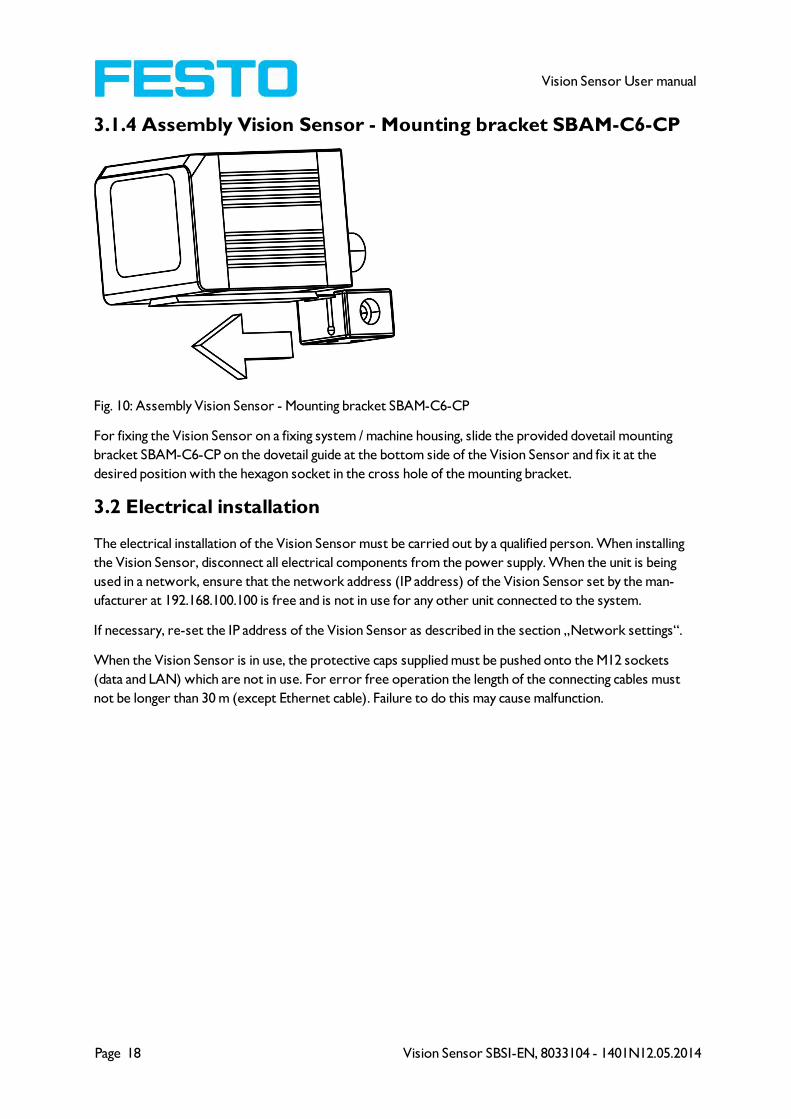
3.1.4 Assembly Vision Sensor - Mounting bracket SBAM-C6-CP
Fig. 10: Assembly Vision Sensor - Mounting bracket SBAM-C6-CP
For fixing the Vision Sensor on a fixing system / machine housing, slide the provided dovetail mounting
bracket SBAM-C6-CP on the dovetail guide at the bottom side of the Vision Sensor and fix it at the
desired position with the hexagon socket in the cross hole of the mounting bracket.
3.2 Electrical installation
The electrical installation of the Vision Sensor must be carried out by a qualified person. When installing
the Vision Sensor, disconnect all electrical components from the power supply. When the unit is being
used in a network, ensure that the network address (IP address) of the Vision Sensor set by the man-
ufacturer at 192.168.100.100 is free and is not in use for any other unit connected to the system.
If necessary, re-set the IP address of the Vision Sensor as described in the section „Network settings“.
When the Vision Sensor is in use, the protective caps supplied must be pushed onto the M12 sockets
(data and LAN) which are not in use. For error free operation the length of the connecting cables must
not be longer than 30 m (except Ethernet cable). Failure to do this may cause malfunction.
Vision Sensor SBSI-EN, 8033104 - 1401N12.05.2014 Page 19
Vision Sensor User manual
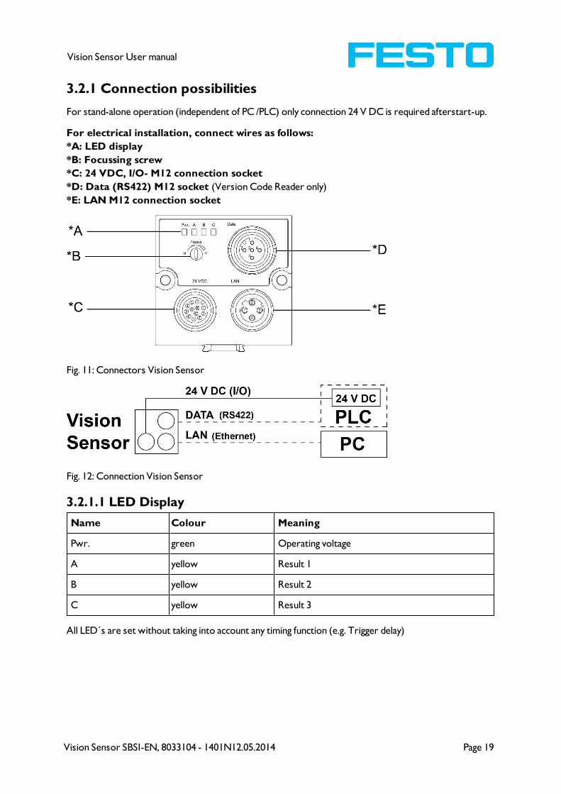
3.2.1 Connection possibilities
For stand-alone operation (independent of PC /PLC) only connection 24 V DC is required afterstart-up.
For electrical installation, connect wires as follows:
*A: LED display
*B: Focussing screw
*C: 24 VDC, I/O- M12 connection socket
*D: Data (RS422) M12 socket (Version Code Reader only)
*E: LAN M12 connection socket
Fig. 11: Connectors Vision Sensor
Fig. 12: Connection Vision Sensor
3.2.1.1 LED Display
Name Colour Meaning
Pwr. green Operating voltage
A yellow Result 1
B yellow Result 2
C yellow Result 3
All LED´s are set without taking into account any timing function (e.g. Trigger delay)
Page 20 Vision Sensor SBSI-EN, 8033104 - 1401N12.05.2014
Vision Sensor User manual
3.2.1.2 Focussing screw
Focussing screw to adjust focus.
Focus: Clockwise = higher distance
Counter Clockwise = lower distance
3.2.1.3 24 V DC Connection
M12 Connection socket for 24 V DC voltage supply and digital I/O.
For the exact plug connection see PIN assignment, connection 24 V DC
3.2.1.4 LAN Connection
M12 Connection socket for Ethernet connection.
For the exact plug connection see PIN assignment, connection LAN .
Use only the correct network cables.
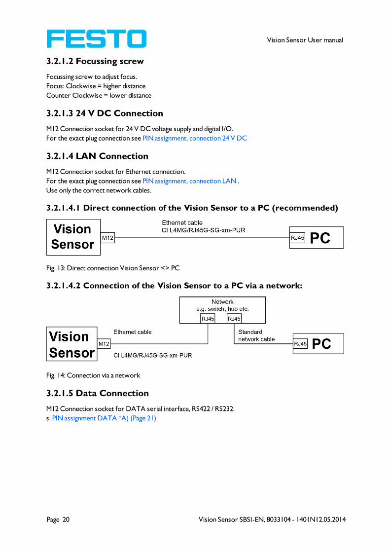
3.2.1.4.1 Direct connection of the Vision Sensor to a PC (recommended)
Fig. 13: Direct connection Vision Sensor <> PC
3.2.1.4.2 Connection of the Vision Sensor to a PC via a network:
Fig. 14: Connection via a network
3.2.1.5 Data Connection
M12 Connection socket for DATA serial interface, RS422 / RS232.
s. PIN assignment DATA *A) (Page 21)

Vision Sensor SBSI-EN, 8033104 - 1401N12.05.2014 Page 21
Vision Sensor User manual
3.2.1.6 Plug connections
All pin assignments and signals are referring to the view from the sensor.
3.2.1.6.1 PIN assignment, connection 24 V DC
PIN Colour Use
1 BN + Ub (24V DC)
2 BU GND
3 WH IN (external trigger)
4 GN READY *1
5 *2 PK IN/OUT (encoder B+)
6 *2 YE IN/OUT
7 *2 BK IN/OUT, LED B*4
8 *2 GY IN/OUT, LED C*4
9 RD OUT (external illumination)
10 VT IN (encoder A+)
11 GYPK VALID *3
12 RDBU OUT (ejector, max. 100mA), LED A*4
*1 Ready: Ready for next ext. trigger.
*2 Switchable input- output
*3 VALID: shows available results
*4 All LED´s are set without taking into account any timing function (e.g. Trigger delay)
For shielded cables use shield.
3.2.1.6.2 PIN assignment, connection LAN
(M12) 4 pin Signal
1 TxD+
2 RxD+
3 TxD-
4 RxD-
3.2.1.6.3 PIN assignment DATA *A)
PIN ColourUse
RS422
use
RS232
1 brown RxD+ Rx

Page 22 Vision Sensor SBSI-EN, 8033104 - 1401N12.05.2014
Vision Sensor User manual
2 white RxD- NC
3 blue TxD+ NC
4 black TxD- Tx
5 grey GND GND
*A) Not with Object- Standard version
For shielded cables use shield.
3.2.1.7 Exemplary connection plan and software settings for the
following setup:
l Power supply
l Trigger
l 1x digital output
l Encoder
l Ethernet to PC or PLC
Fig. 15: Exemplary connection plan

Vision Sensor SBSI-EN, 8033104 - 1401N12.05.2014 Page 23
Vision Sensor User manual
3.2.1.8 Electrical connection supply voltage and shield
Fig. 16: Electrical connection, supply voltage 24VDC in cabinet with shield
3.2.1.9 Electrical connection PNP / NPN
Fig. 17: Connection example Vision Sensor in PNP mode. In-/outputs switch to +24V
Fig. 18: Connection example Vision Sensor in NPN mode
As the inputs refer to ground, an additional pull-up resistor may be required in order to increase the input
voltage to 24V when unswitched. The outputs switch to ground.

Page 24 Vision Sensor SBSI-EN, 8033104 - 1401N12.05.2014
Vision Sensor User manual
3.3 Network settings, Short reference
The following instructions indicate how to change the network configuration of the PC and the Vision
Sensor. If incorrect settings are used, the network connections in the computer may be lost. To be on
the safe side, note the former settings for later use if required.
Following this procedure, it may be necessary to re-start the system. In order to determine which IP
addresses are allowed in your network or locally in your PC, and to carry out the necessary settings on
your PC, contact the system administrator beforehand.
The illustrations, dialogues and menus originate from the operating system Microsoft
WindowsXPTM. The illustrations are similar in other operating systems.
3.3.1 Basic settings for PC and Vision Sensor
To configure the Vision Sensor with a PC it is essential that a network board and the TCP/IP LAN- con-
nection is installed on the PC (This also applies when the PC is not connected to a network). The Vision
Sensor supports the automatic recognition of the Ethernet transmission rate, but 100 MBit at the most.
The internet protocol IPv4 must be activated.
There are two alternatives to configure and parameterize the Vision Sensor.
See also chap. Network connection
1. Direct Connection
2. Network Connection

Vision Sensor SBSI-EN, 8033104 - 1401N12.05.2014 Page 25
Vision Sensor User manual
3.3.2 Direct Connection - Setting the IP Address of the PC
To connect the Vision Sensor to a PC via Ethernet the IP addresses of both devices have to correspond.
The default IP of the Vision Sensor is 192.168.100.100 with Subnet mask = 255.255.255.0. To establish a
direct connection, the PC must be set to a corresponding, fixed IP address like follows.
1. Click on Start / Control Panel / Network Connection / LAN Connection / Properties, the window
"Local Area Connection Properties" opens.
2. In the list „This connection requires following elements“ select the option „Internet Protocol
(TCP/IP)“ and then click the button „Properties“.
3. In the following window set the desired IP address of the PC and the sub-network data.
4. Confirm entries with OK
Example:
The Vision Sensor is pre-set to IP address 192.168.100.100 and subnet mask 255.255.255.0.
In this case, the IP address may be set to any value between 192.168.100.1 and 192.168.100.254, with a sub-
net mask 255.255.255.0, with the exception of the sensor IP address (192.168.100.100).
To alter the sensor’s IP address, see chap. Please do also not use the addresses .0 and .255 as these
addresses are reserved for network infrastructure devices such as servers, gateways, etc.
Fig. 19: PC IP Setup

Page 26 Vision Sensor SBSI-EN, 8033104 - 1401N12.05.2014
Vision Sensor User manual
3.3.3 Network Connection - Setting the IP address of the Vision
Sensor
Before connecting the sensor in the network, check with the network administrator whether the
sensor’s address has already been assigned (default: 192.168.100.100 with subnet mask 255.255.255.0).
This can otherwise cause network failure. The set IP address is to be noted on the enclosed label. The
label is then to be stuck on the sensor in a clearly visible place after installation.
Network connection speed:
The sensor must only be operated with 100MBit/full-duplex when using VGA resolution (or higher) and
Vision Sensor Visualisation Studio.
Sensor’s IP still free:
Connect sensor to network and then set the sensor’s IP to match the PC according to the admin-
istrator’s specifications, as follows, beginning with 2.
Sensor IP already assigned:
1. First connect sensor and PC directly and set an authorised IP address in the sensor.
2. Connection via the network can then be carried out. First ensure electrical connection and install-
ation of PC software has been completed. To set the IP address on the Vision Sensor, the fol-
lowing steps are to be carried out in the PC software:
a. Start Vision Sensor Device Manager software
b. Select the required Vision Sensor sensor from the active sensor list (single left mouse
click)
c. Set sensor’s new IP address with the “Set” button. Follow the on screen prompts. The IP
address is assigned by your system administrator. The PC’s IP address is shown in the
status bar under the buttons. (Please note some pc’s have more than one Ethernet con-
nection i.e. wireless and wired LAN connections
d. When the new IP address has been set, Re-select the sensor and connect. Via Config or
View
Vision Sensor SBSI-EN, 8033104 - 1401N12.05.2014 Page 27
Vision Sensor User manual
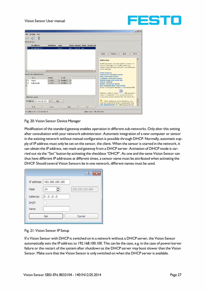
Fig. 20: Vision Sensor Device Manager
Modification of the standard gateway enables operation in different sub-networks. Only alter this setting
after consultation with your network administrator. Automatic integration of a new computer or sensor
in the existing network without manual configuration is possible through DHCP. Normally, automatic sup-
ply of IP address must only be set on the sensor, the client. When the sensor is started in the network, it
can obtain the IP address, net mask and gateway from a DHCP server. Activation of DHCP mode is car-
ried out via the “Set” button by activating the checkbox “DHCP“. As one and the same Vision Sensor can
thus have different IP addresses at different times, a sensor name must be attributed when activating the
DHCP. Should several Vision Sensors be in one network, different names must be used.
Fig. 21: Vision Sensor IP Setup
If a Vision Sensor with DHCP is switched on in a network without a DHCP server, the Vision Sensor
automatically sets the IP address to 192.168.100.100. This can be the case, e.g. in the case of power/server
failure or the restart of the system after shutdown as the DHCP server may boot slower than the Vision
Sensor. Make sure that the Vision Sensor is only switched on when the DHCP server is available.

Page 28 Vision Sensor SBSI-EN, 8033104 - 1401N12.05.2014
Vision Sensor User manual
4 Vision Sensor – Operating- and configuration software
4.1 Vision Sensor – Operating- and configuration software - Over-
view
4.1.1 Structure of PC software
The PC software is organised into the following three sections:
l Vision Sensor – Operating- and configuration software – Short introduction (Page 29)
For selection of a Vision Sensor sensor, or a sensor simulation model, for configuration with the
“Vision Sensor Configuration Studio” tool or display (monitoring) with the “Vision Sensor Visu-
alisation Studio” tool, or modification of different system settings such as IP addresses, firmware
updates with the “Set” tool.
l Vision Sensor Configuration Studio:
Complete set of functions to configure and test Vision Sensor for one or several inspection tasks
(jobs) in six simple logical operating steps.
l Vision Sensor Visualisation Studio:
For the display and monitoring of images and results from connected sensors, as well as job switch
and job upload.
Fig. 22: Software structure
4.1.2 Context help
For all software functions a context sensitive help page is available and displayed as soon as a function is
selected.
Vision Sensor SBSI-EN, 8033104 - 1401N12.05.2014 Page 29
Vision Sensor User manual
All available help pages can be viewed by pressing the Help- button („?“ symbol) or by double click to the
online help window. There you also can do a keyword search. In comparison to the context help the size
of this help window can be enlarged to view longer text more comfortable.
12.05.2014
4.2 Vision Sensor – Operating- and configuration software –
Short introduction
(Example: Object sensor)
4.2.1 Vision Sensor, Short introduction, Starting the software
This short guide explains step by step the procedure for setting an example inspection task on the vision
sensor
To start the Vision Sensor application click to the desktop icon "Vision Sensor“.
Fig. 23: Icon Vision Sensor
4.2.2 Vision Sensor Device Manager: Open sensors or sensor sim-
ulation / Passwords
In this program, you can select a sensor or a sensor simulation for configuration or display (monitoring)
and carry out different basic settings.
Next topic: Vision Sensor Configuration Studio: Setting sensor, Job (Page 33)
Configuring or displaying sensors
In order to open a sensor for configuration or display, select with a single left mouse click the required
sensor in the "Active sensors“ list, then click on the button "Config“ to start the "Vision Sensor Con-
figuration Studio“ software, or on the button "View“ for the "Vision Sensor Visualisation Studio“ soft-
ware.
Sensor simulation
To open a sensor for offline simulation, select the required sensor in the "Sensors for simulation mode“
list, then click on the button "Config“ to start the module "Vision Sensor Configuration Studio“. Vision
Sensor Visualisation Studio is not available for the simulation mode as there is no device to send the
images for display.
Page 30 Vision Sensor SBSI-EN, 8033104 - 1401N12.05.2014
Vision Sensor User manual
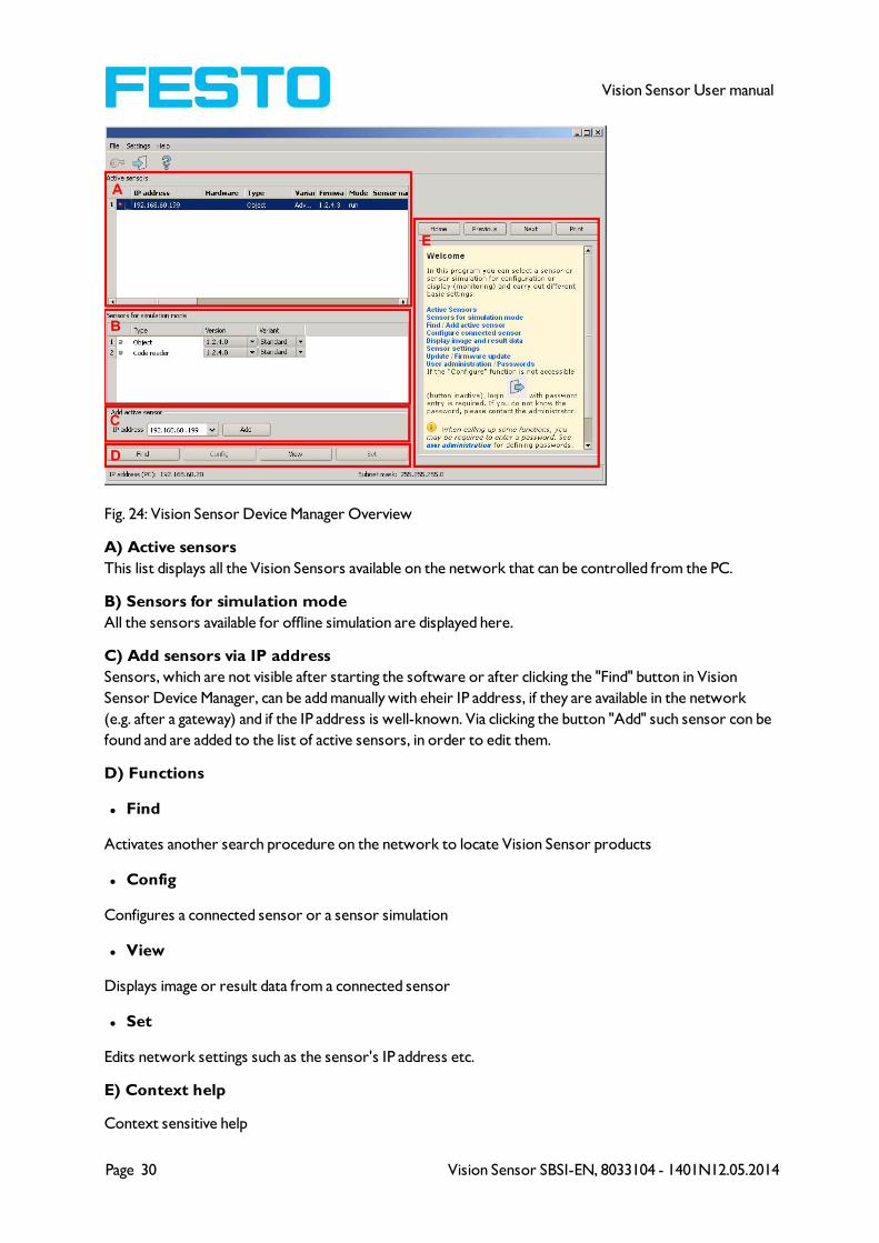
Fig. 24: Vision Sensor Device Manager Overview
A) Active sensors
This list displays all the Vision Sensors available on the network that can be controlled from the PC.
B) Sensors for simulation mode
All the sensors available for offline simulation are displayed here.
C) Add sensors via IP address
Sensors, which are not visible after starting the software or after clicking the "Find" button in Vision
Sensor Device Manager, can be add manually with eheir IP address, if they are available in the network
(e.g. after a gateway) and if the IP address is well-known. Via clicking the button "Add" such sensor con be
found and are added to the list of active sensors, in order to edit them.
D) Functions
l Find
Activates another search procedure on the network to locate Vision Sensor products
l Config
Configures a connected sensor or a sensor simulation
l View
Displays image or result data from a connected sensor
l Set
Edits network settings such as the sensor's IP address etc.
E) Context help
Context sensitive help
Vision Sensor SBSI-EN, 8033104 - 1401N12.05.2014 Page 31
Vision Sensor User manual
4.2.3 Passwords
When first started-up after installation, password entry is completely deactivated and auto login is preset
to administrator.
If parameter settings are to be protected from unauthorised access, passwords should be given for the
"Admin“ and "User“ password levels, see below. This can be called up via the menu bar File / User admin-
istration or via the button with the key symbol in the toolbar.
Fig. 25: Password button
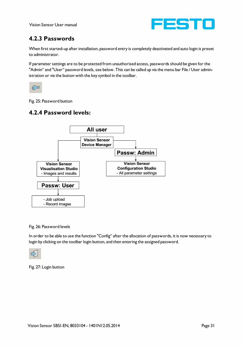
4.2.4 Password levels:
Fig. 26: Password levels
In order to be able to use the function "Config“ after the allocation of passwords, it is now necessary to
login by clicking on the toolbar login button, and then entering the assigned password.
Fig. 27: Login button

Page 32 Vision Sensor SBSI-EN, 8033104 - 1401N12.05.2014
Vision Sensor User manual
Fig. 28: Password input
Allocating an empty password means the password can be confirmed without any further entry. Activ-
ation of the "Deactivate password request“ checkbox, permanently deactivates password request.
If passwords have been assigned and then forgotten, it is possible to reset passwords to delivery status
by reinstalling the software on the local PC.

Vision Sensor SBSI-EN, 8033104 - 1401N12.05.2014 Page 33
Vision Sensor User manual
4.3 Vision Sensor Configuration Studio: Setting sensor, Job
With this program, you can configure your Vision Sensor for one or several jobs in six simple logical oper-
ating steps.
Next topic: Alignment settings (Page 35)
Fig. 29: Vision Sensor Configuration Studio
The fields are:
A) Menu and tool bar
B) Setup Navigation / Operating steps
See next chapter for description
C) Image
Image output with graphically adjustable operating and search zones as well as zoom function also
filmstrip navigation when in simulation mode
D) Context
Context-sensitive online help, automatically updated for each action.
Page 34 Vision Sensor SBSI-EN, 8033104 - 1401N12.05.2014
Vision Sensor User manual
E) Image acquisition mode
Switch-over between continuous (free run) and single image mode with trigger input (either from sensor
or via onscreen button)
F) Connection mode
Switch-over between online and offline mode (sensor present or simulation without sensor)
G) Job selection
Changing variable content relating to action in set-up navigation, for setting of associated parameters.
H) Status bar
Different status information including Mode / Name of Vision Sensor / Active job. In Run Mode: Cycle
time / cursor x/y location and pixel intensity / individual I/O on /off indication (like configured in "Out-
put/Digital output").
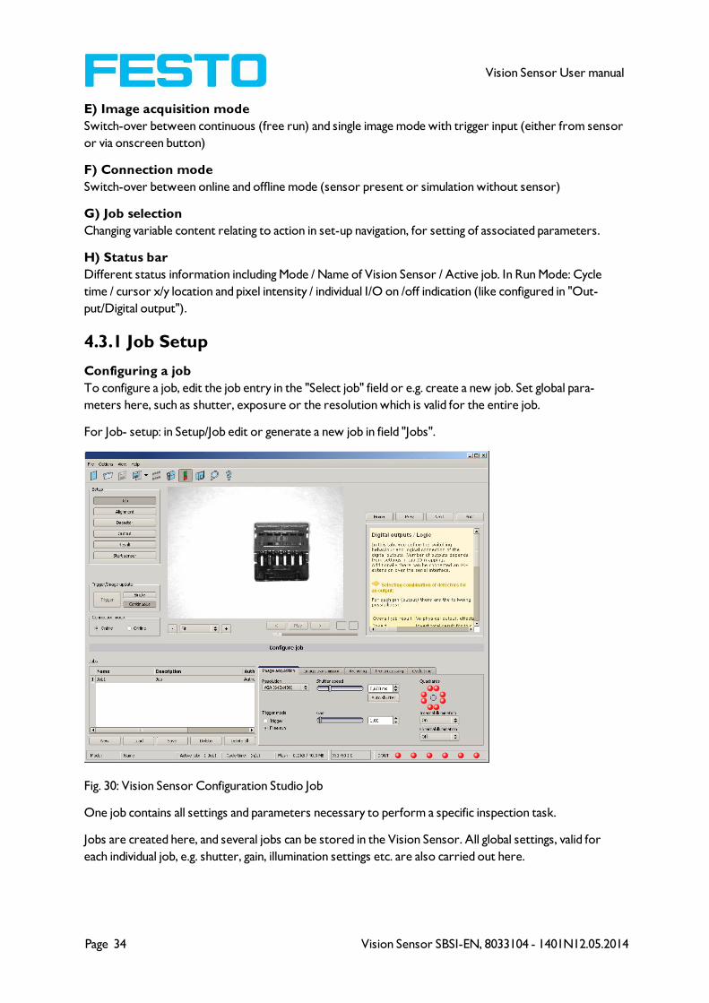
4.3.1 Job Setup
Configuring a job
To configure a job, edit the job entry in the "Select job" field or e.g. create a new job. Set global para-
meters here, such as shutter, exposure or the resolution which is valid for the entire job.
For Job- setup: in Setup/Job edit or generate a new job in field "Jobs".
Fig. 30: Vision Sensor Configuration Studio Job
One job contains all settings and parameters necessary to perform a specific inspection task.
Jobs are created here, and several jobs can be stored in the Vision Sensor. All global settings, valid for
each individual job, e.g. shutter, gain, illumination settings etc. are also carried out here.
Vision Sensor SBSI-EN, 8033104 - 1401N12.05.2014 Page 35
Vision Sensor User manual
l The following basic image settings should first be made to ensure a high-contrast and sharp image:
* Image brightness: Set shutter or amplification, see Job/General
* Image sharpness: Focus setting via the screw on the back of the Vision Sensor camera itself
l When delivered, the factory settings are trigger mode = "free run" (see Job/General) and image acquis-
ition mode = "continuous" . A new image is continuously displayed for easier focus and brightness set
up.
l The subsequent setting of alignment and detectors should preferably be carried out in single image
mode, as all settings are then based on a master image and image collection is not continuously carried
out.
l Alignment and multiple different detectors can subsequently be defined within one job to solve an
inspection task.
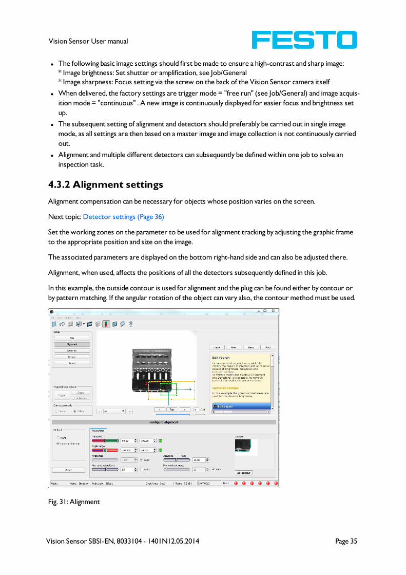
4.3.2 Alignment settings
Alignment compensation can be necessary for objects whose position varies on the screen.
Next topic: Detector settings (Page 36)
Set the working zones on the parameter to be used for alignment tracking by adjusting the graphic frame
to the appropriate position and size on the image.
The associated parameters are displayed on the bottom right-hand side and can also be adjusted there.
Alignment, when used, affects the positions of all the detectors subsequently defined in this job.
In this example, the outside contour is used for alignment and the plug can be found either by contour or
by pattern matching. If the angular rotation of the object can vary also, the contour method must be used.
Fig. 31: Alignment

Page 36 Vision Sensor SBSI-EN, 8033104 - 1401N12.05.2014
Vision Sensor User manual
4.3.3 Detector settings
Different detectors can be selected and adjusted to solve an inspection task. First the required detector
is selected in the dialog box shown below.
Fig. 32: Detector list, Object sensor
Then the working and search zones are graphically set on the screen. If “teach zones” (red outline) exist,
they are taught immediately after completion of the settings. All the detectors defined in this job are
shown in the bottom left-hand corner. The parameters of the currently selected detector are shown in
the bottom right-hand corner and can be adjusted there.
If other parameters are to be checked on the same part, many other detectors can be created as
described above by clicking on "New".
In the example two brightness detectors are defined to check the presence of metal contacts in a plastic
connector housing.
Detector 1: contact found (brightness value is in defined range as the shiny metal contact is mounted) res-
ult positive.
Detector 2: contact not found (brightness value out of defined range, as only weak reflection from the
black plastic housing background) result negative.
Vision Sensor SBSI-EN, 8033104 - 1401N12.05.2014 Page 37
Vision Sensor User manual
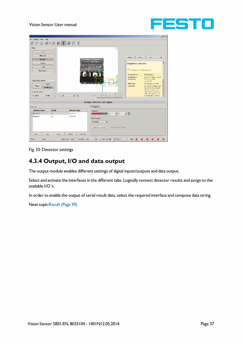
Fig. 33: Detector settings
4.3.4 Output, I/O and data output
The output module enables different settings of digital inputs/outputs and data output.
Select and activate the interfaces in the different tabs. Logically connect detector results and assign to the
available I/O´s.
In order to enable the output of serial result data, select the required interface and compose data string.
Next topic:Result (Page 39)
Page 38 Vision Sensor SBSI-EN, 8033104 - 1401N12.05.2014
Vision Sensor User manual
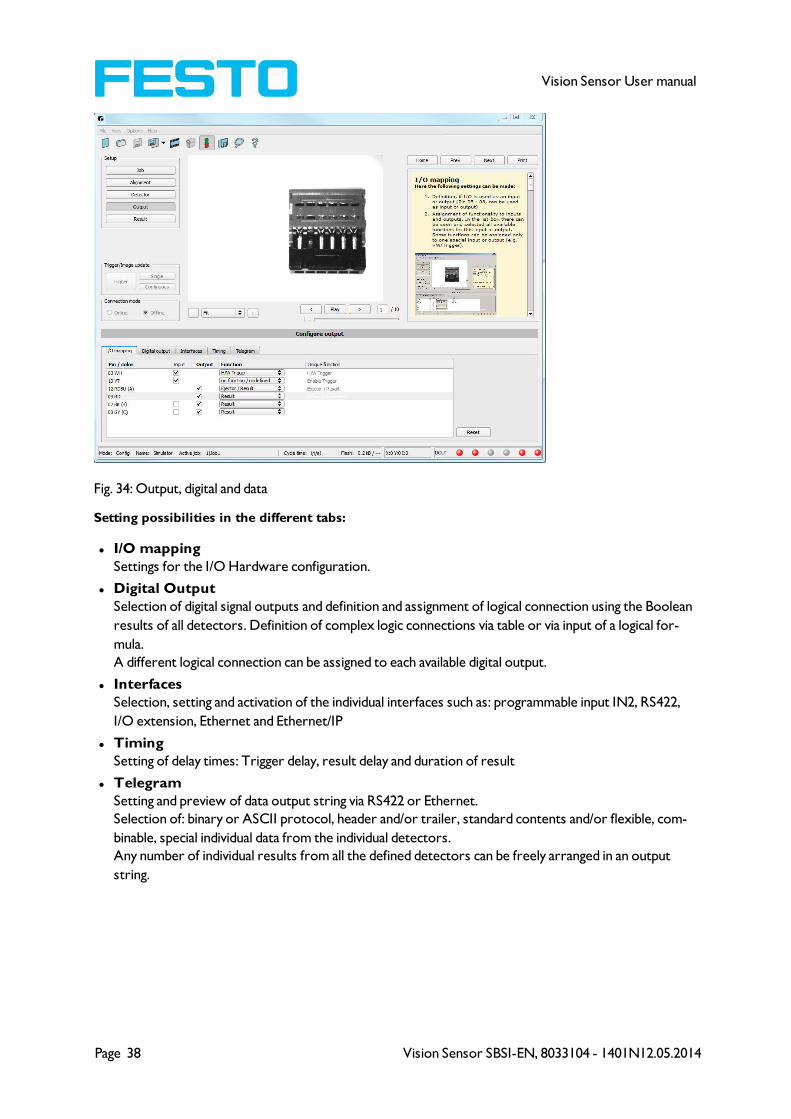
Fig. 34: Output, digital and data
Setting possibilities in the different tabs:
l I/O mapping
Settings for the I/O Hardware configuration.
l Digital Output
Selection of digital signal outputs and definition and assignment of logical connection using the Boolean
results of all detectors. Definition of complex logic connections via table or via input of a logical for-
mula.
A different logical connection can be assigned to each available digital output.
l Interfaces
Selection, setting and activation of the individual interfaces such as: programmable input IN2, RS422,
I/O extension, Ethernet and Ethernet/IP
l Timing
Setting of delay times: Trigger delay, result delay and duration of result
l Telegram
Setting and preview of data output string via RS422 or Ethernet.
Selection of: binary or ASCII protocol, header and/or trailer, standard contents and/or flexible, com-
binable, special individual data from the individual detectors.
Any number of individual results from all the defined detectors can be freely arranged in an output
string.

Vision Sensor SBSI-EN, 8033104 - 1401N12.05.2014 Page 39
Vision Sensor User manual
4.3.5 Result
With this function, an inspection is carried out on the PC for control purposes, using all the settings made.
All the results are produced and displayed just as on the sensor. However e.g. execution times will not be
updated as these values are only informative when implemented on the sensor itself. See next step: „Start
Sensor“.
Next topic: Start sensor (Page 40)
Fig. 35: Result display

Page 40 Vision Sensor SBSI-EN, 8033104 - 1401N12.05.2014
Vision Sensor User manual
4.3.6 Start sensor
When this function is activated, all settings are transferred to the sensor, stored in the flash memory and
carried out in e.g. in free run or in triggered mode according to the settings made. All information in the
list of detectors, result field or under „Statistics“ is updated here.
If using “triggered mode” then a trigger will be required from the external control system, alternatively a
‘software’ trigger can be sent using the Trigger button the left hand side of the image area.
Next topic: Vision Sensor Visualisation Studio, display images and results (Page 41)
Fig. 36: Start sensor
Vision Sensor SBSI-EN, 8033104 - 1401N12.05.2014 Page 41
Vision Sensor User manual
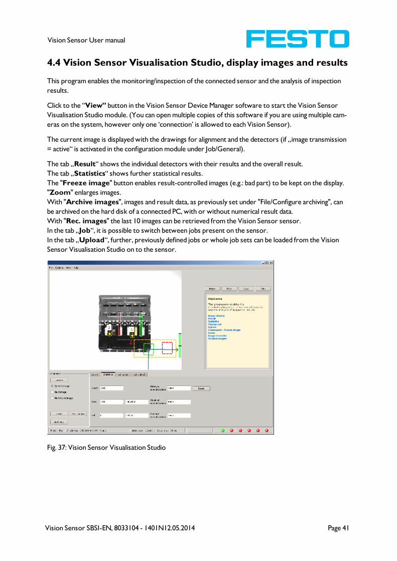
4.4 Vision Sensor Visualisation Studio, display images and results
This program enables the monitoring/inspection of the connected sensor and the analysis of inspection
results.
Click to the “View” button in the Vision Sensor Device Manager software to start the Vision Sensor
Visualisation Studio module. (You can open multiple copies of this software if you are using multiple cam-
eras on the system, however only one ‘connection’ is allowed to each Vision Sensor).
The current image is displayed with the drawings for alignment and the detectors (if „image transmission
= active“ is activated in the configuration module under Job/General).
The tab „Result“ shows the individual detectors with their results and the overall result.
The tab „Statistics“ shows further statistical results.
The "Freeze image" button enables result-controlled images (e.g.: bad part) to be kept on the display.
"Zoom" enlarges images.
With "Archive images", images and result data, as previously set under "File/Configure archiving", can
be archived on the hard disk of a connected PC, with or without numerical result data.
With "Rec. images" the last 10 images can be retrieved from the Vision Sensor sensor.
In the tab „Job“, it is possible to switch between jobs present on the sensor.
In the tab „Upload“, further, previously defined jobs or whole job sets can be loaded from the Vision
Sensor Visualisation Studio on to the sensor.
Fig. 37: Vision Sensor Visualisation Studio
Page 42 Vision Sensor SBSI-EN, 8033104 - 1401N12.05.2014
Vision Sensor User manual
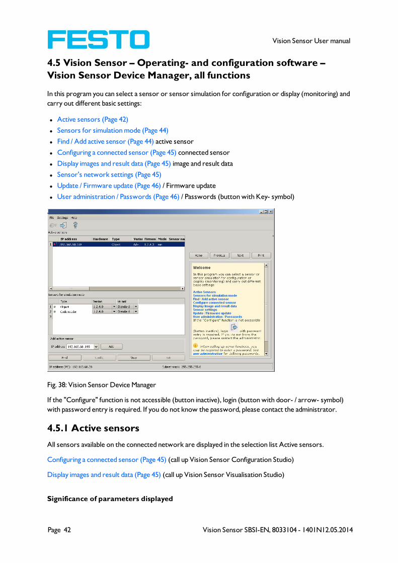
4.5 Vision Sensor – Operating- and configuration software –
Vision Sensor Device Manager, all functions
In this program you can select a sensor or sensor simulation for configuration or display (monitoring) and
carry out different basic settings:
l Active sensors (Page 42)
l Sensors for simulation mode (Page 44)
l Find / Add active sensor (Page 44) active sensor
l Configuring a connected sensor (Page 45) connected sensor
l Display images and result data (Page 45) image and result data
l Sensor's network settings (Page 45)
l Update / Firmware update (Page 46) / Firmware update
l User administration / Passwords (Page 46) / Passwords (button with Key- symbol)
Fig. 38: Vision Sensor Device Manager
If the "Configure" function is not accessible (button inactive), login (button with door- / arrow- symbol)
with password entry is required. If you do not know the password, please contact the administrator.
4.5.1 Active sensors
All sensors available on the connected network are displayed in the selection list Active sensors.
Configuring a connected sensor (Page 45) (call up Vision Sensor Configuration Studio)
Display images and result data (Page 45) (call up Vision Sensor Visualisation Studio)
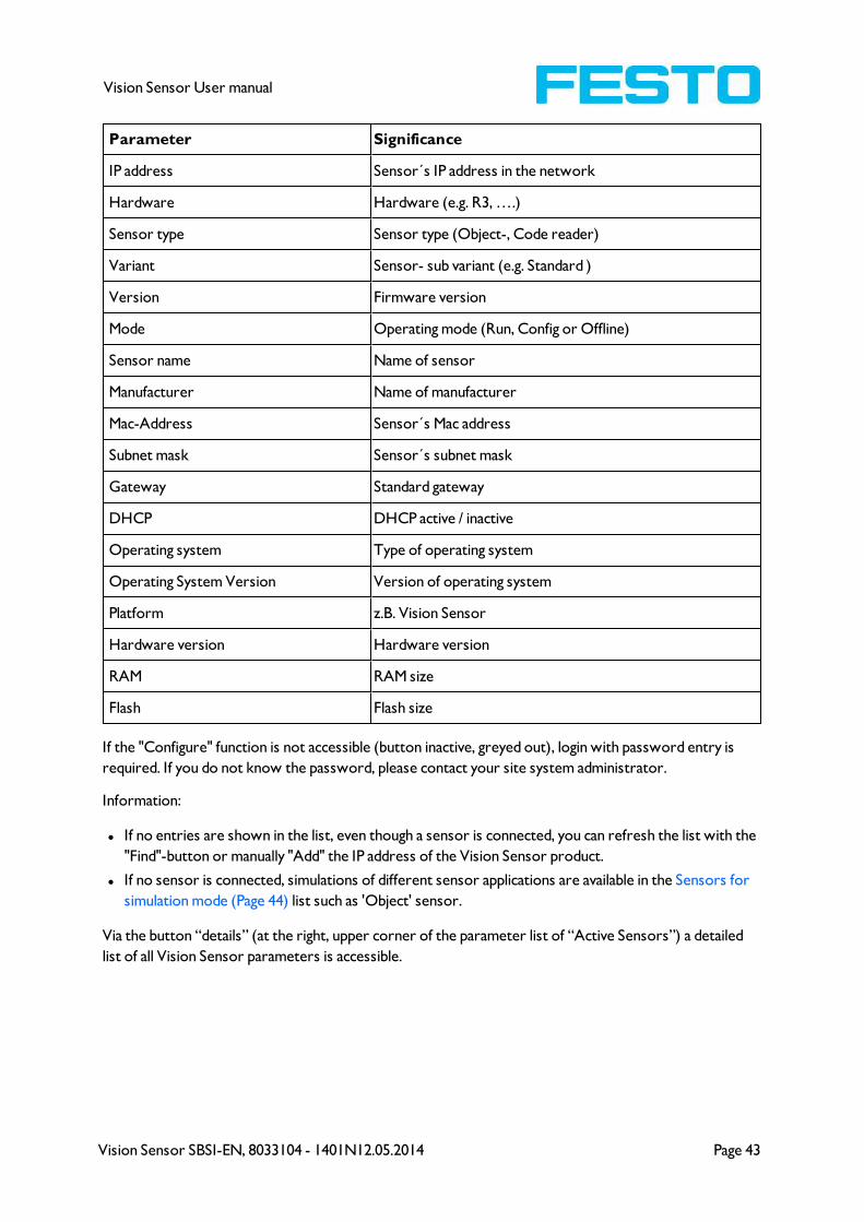
Significance of parameters displayed
Vision Sensor SBSI-EN, 8033104 - 1401N12.05.2014 Page 43
Vision Sensor User manual
Parameter Significance
IP address Sensor´s IP address in the network
Hardware Hardware (e.g. R3, ….)
Sensor type Sensor type (Object-, Code reader)
Variant Sensor- sub variant (e.g. Standard )
Version Firmware version
Mode Operating mode (Run, Config or Offline)
Sensor name Name of sensor
Manufacturer Name of manufacturer
Mac-Address Sensor´s Mac address
Subnet mask Sensor´s subnet mask
Gateway Standard gateway
DHCP DHCP active / inactive
Operating system Type of operating system
Operating System Version Version of operating system
Platform z.B. Vision Sensor
Hardware version Hardware version
RAM RAM size
Flash Flash size
If the "Configure" function is not accessible (button inactive, greyed out), login with password entry is
required. If you do not know the password, please contact your site system administrator.
Information:
l If no entries are shown in the list, even though a sensor is connected, you can refresh the list with the
"Find"-button or manually "Add" the IP address of the Vision Sensor product.
l If no sensor is connected, simulations of different sensor applications are available in the Sensors for
simulation mode (Page 44) list such as 'Object' sensor.
Via the button “details” (at the right, upper corner of the parameter list of “Active Sensors”) a detailed
list of all Vision Sensor parameters is accessible.
Page 44 Vision Sensor SBSI-EN, 8033104 - 1401N12.05.2014
Vision Sensor User manual
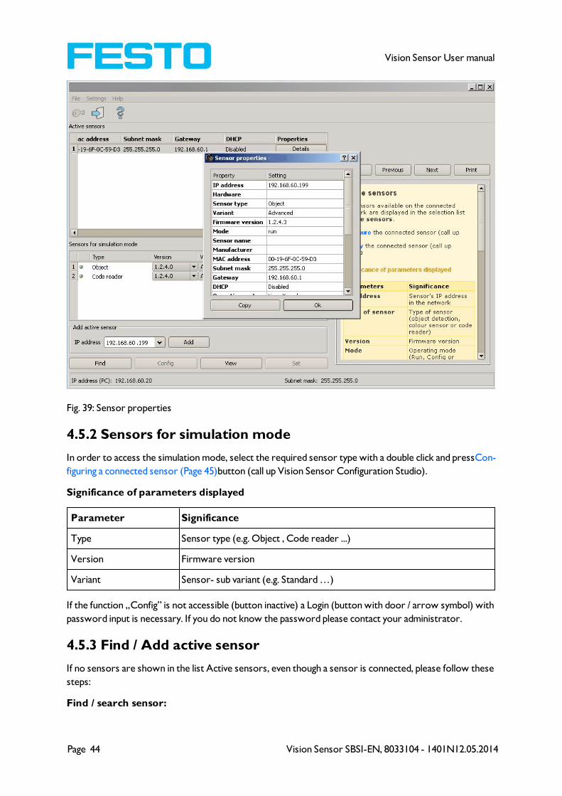
Fig. 39: Sensor properties
4.5.2 Sensors for simulation mode
In order to access the simulation mode, select the required sensor type with a double click and pressCon-
figuring a connected sensor (Page 45)button (call up Vision Sensor Configuration Studio).
Significance of parameters displayed
Parameter Significance
Type Sensor type (e.g. Object , Code reader ...)
Version Firmware version
Variant Sensor- sub variant (e.g. Standard …)
If the function „Config” is not accessible (button inactive) a Login (button with door / arrow symbol) with
password input is necessary. If you do not know the password please contact your administrator.
4.5.3 Find / Add active sensor
If no sensors are shown in the list Active sensors, even though a sensor is connected, please follow these
steps:
Find / search sensor:

Vision Sensor SBSI-EN, 8033104 - 1401N12.05.2014 Page 45
Vision Sensor User manual
To search for sensors which are connected directly to the PC, or which are available in the network, click
button "Find". Basic understanding of PC networking is required.
Add active sensor:
If you know the IP-address of a sensor, please enter it into the field IP-address and click button "Add".
Now the sensor appears in the list and can be accessed for e.g. Config or View.
If the function "Config" is not accessible (button not active / greyed out) a Login with password input is
necessary. If you do not know the password please contact your site systems administrator.
4.5.4 Configuring a connected sensor
Mark a sensor (simulation) in the list and click on the "Config" button.
The configuration program Vision Sensor Configuration Studio is called up and the jobs currently stored
on the sensor are shown in the selection list.
When Vision Sensor Configuration Studio is called up, you may be required to enter a password. See
User administration / Passwords (Page 46) for defining passwords.
s. chap Vision Sensor Configuration Studio Vision Sensor – Operating- and configuration software –
Vision Sensor Configuration Studio, all functions
4.5.5 Display images and result data
Mark a sensor in the list and click on the "View" button.
The Vision Sensor Visualisation Studio program is opened up and images and measurement results from
the active jobs are displayed on screen.
Information:
Calling up Vision Sensor Visualisation Studio does not affect operation of the selected sensor.
s. chap. Vision Sensor Visualisation Studio Vision Sensor – Operating- and configuration software –
Vision Sensor Visualisation Studio, all functions
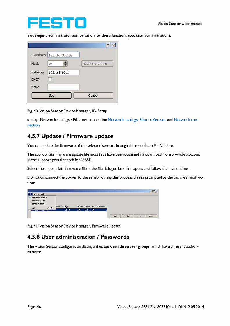
4.5.6 Sensor's network settings
You can change the network settings of the selected sensor with the Set button.
The IP address, subnet mask, standard gateway, DHCP and sensor name can be set here.
The PC's IP address and subnet mask are displayed below in the Vision Sensor Device Manager status bar.
The address structure must be correct in order to be able to connect the sensor to the PC. The sensor's
IP address etc. can therefore be modified accordingly here if necessary.
Please contact your site administrator for the definition of network parameters. Further information on
this subject can be found in the printed manual.
If "DHCP = active" is selected, a unique name must be given for the sensor as the IP address is newly
assigned each time the sensor starts up and can thus change.
Page 46 Vision Sensor SBSI-EN, 8033104 - 1401N12.05.2014
Vision Sensor User manual
You require administrator authorisation for these functions (see user administration).
Fig. 40: Vision Sensor Device Manager, IP- Setup
s. chap. Network settings / Ethernet connection Network settings, Short reference and Network con-
nection
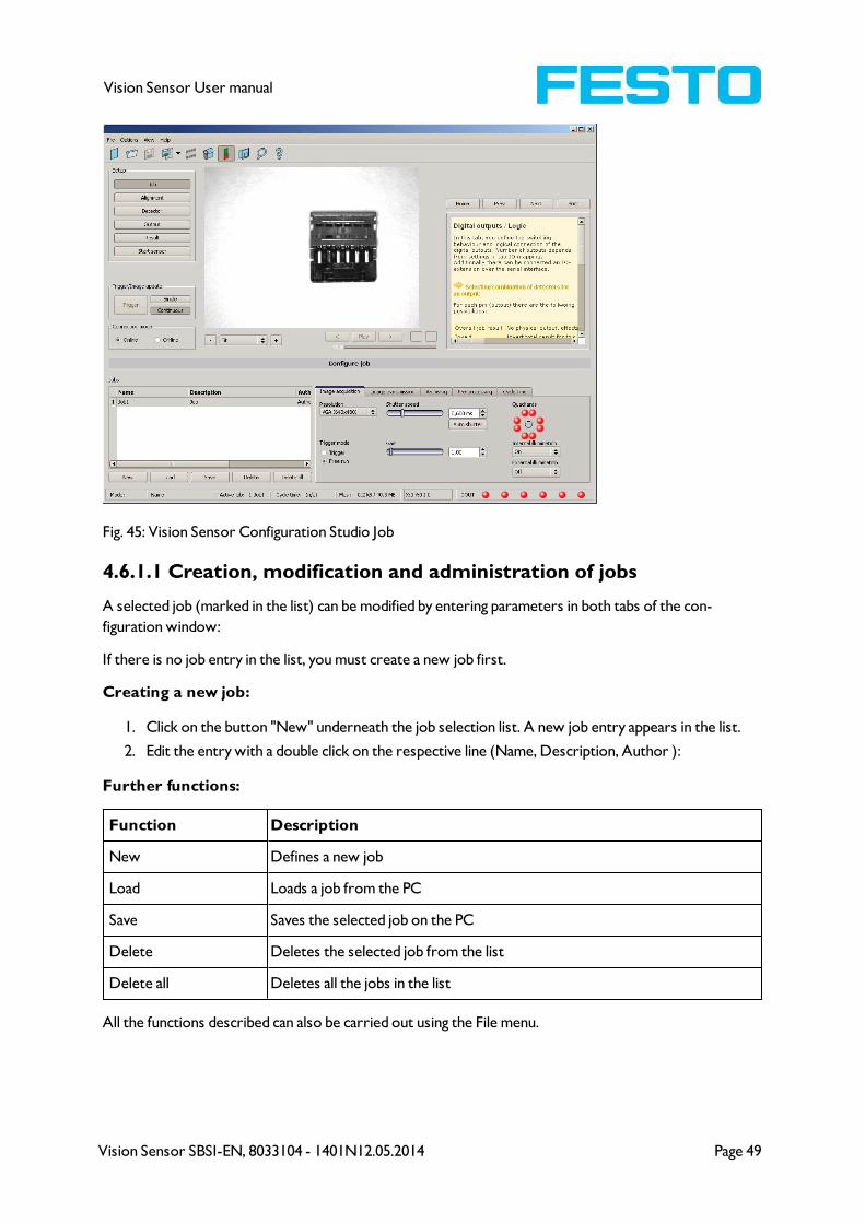
4.5.7 Update / Firmware update
You can update the firmware of the selected sensor through the menu item File/Update.
The appropriate firmware update file must first have been obtained via download from www.festo.com.
In the support portal search for "SBSI".
Select the appropriate firmware file in the file dialogue box that opens and follow the instructions.
Do not disconnect the power to the sensor during this process unless prompted by the onscreen instruc-
tions.
Fig. 41: Vision Sensor Device Manager, Firmware update
4.5.8 User administration / Passwords
The Vision Sensor configuration distinguishes between three user groups, which have different author-
isations:

Vision Sensor SBSI-EN, 8033104 - 1401N12.05.2014 Page 47
Vision Sensor User manual
Fig. 42: Vision Sensor Device Manager, Password input
UserVision Sensor
Device Manager
Vision Sensor Con-
figuration Studio
Vision Sensor Visualisation
Studio
Administrator all functions all functions all functions
Operator
all functions except
- Config.
- settings
-update
none all functions
User
all functions except
- Config.
- settings
-update
noneonly display of images, inspection
results and statistics
After software installation, login is automatically carried-out when the application is called-up, without
password request. No passwords are assigned.
Define passwords:
Select file user administration in the File menu or click on in the toolbar to assign passwords for the
administrator and user categories. Once a password has been entered, a logout is automatically carried
out, i.e. input of the new password is now necessary. Assigning an "empty" password, enables entry by
simply confirming with OK.
Fig. 43: Password button
Login
Once passwords have been assigned and automatic logout has taken place, a login is required e.g. for
sensor configuration. Click on in the tool bar to login and / or (after password entry) to deactivate pass-
word entry for the next session for the selected user group.

Page 48 Vision Sensor SBSI-EN, 8033104 - 1401N12.05.2014
Vision Sensor User manual
If the "deactivate password request" box is ticked, the password will not be requested when the applic-
ation is next started.
Fig. 44: Login- button
4.6 Vision Sensor – Operating- and configuration software –
Vision Sensor Configuration Studio, all functions
With this programme, you can configure your Vision Sensor for one or several jobs in six logical oper-
ating steps.
l Jobs (Inspection tasks) (Page 48)
l Alignment (Page 57)
l Detectors (Page 58)
l Output of inspection results (Page 94)
l Result (Page 110)
l Start sensor (Page 112)
Other program functions:
l Trigger settings (Page 113)
l Switching between online and offline mode (Page 114)
l Simulation of jobs (offline mode) (Page 114) using series of images.
l Creating filmstrips (Page 114) Image recording for analysis or simulation purposes. Use of Vision
Sensor Configuration Studio may require password entry (administrator user group). See User admin-
istration / Passwords (Page 46)
l Image recorder (Page 122)
To obtain a continuously updated live image even without trigger, carry out the following (if necessary
temporary) settings:
l Set to free run in "Job/Image acquisition"
l Set to continuous in "Trigger / collect image" User interface and operating procedure
4.6.1 Jobs (Inspection tasks)
A job contains all the settings and parameters required to carry out a certain inspection task.
Vision Sensor SBSI-EN, 8033104 - 1401N12.05.2014 Page 49
Vision Sensor User manual
Fig. 45: Vision Sensor Configuration Studio Job
4.6.1.1 Creation, modification and administration of jobs
A selected job (marked in the list) can be modified by entering parameters in both tabs of the con-
figuration window:
If there is no job entry in the list, you must create a new job first.
Creating a new job:
1. Click on the button "New" underneath the job selection list. A new job entry appears in the list.
2. Edit the entry with a double click on the respective line (Name, Description, Author ):
Further functions:
Function Description
New Defines a new job
Load Loads a job from the PC
Save Saves the selected job on the PC
Delete Deletes the selected job from the list
Delete all Deletes all the jobs in the list
All the functions described can also be carried out using the File menu.
Page 50 Vision Sensor SBSI-EN, 8033104 - 1401N12.05.2014
Vision Sensor User manual
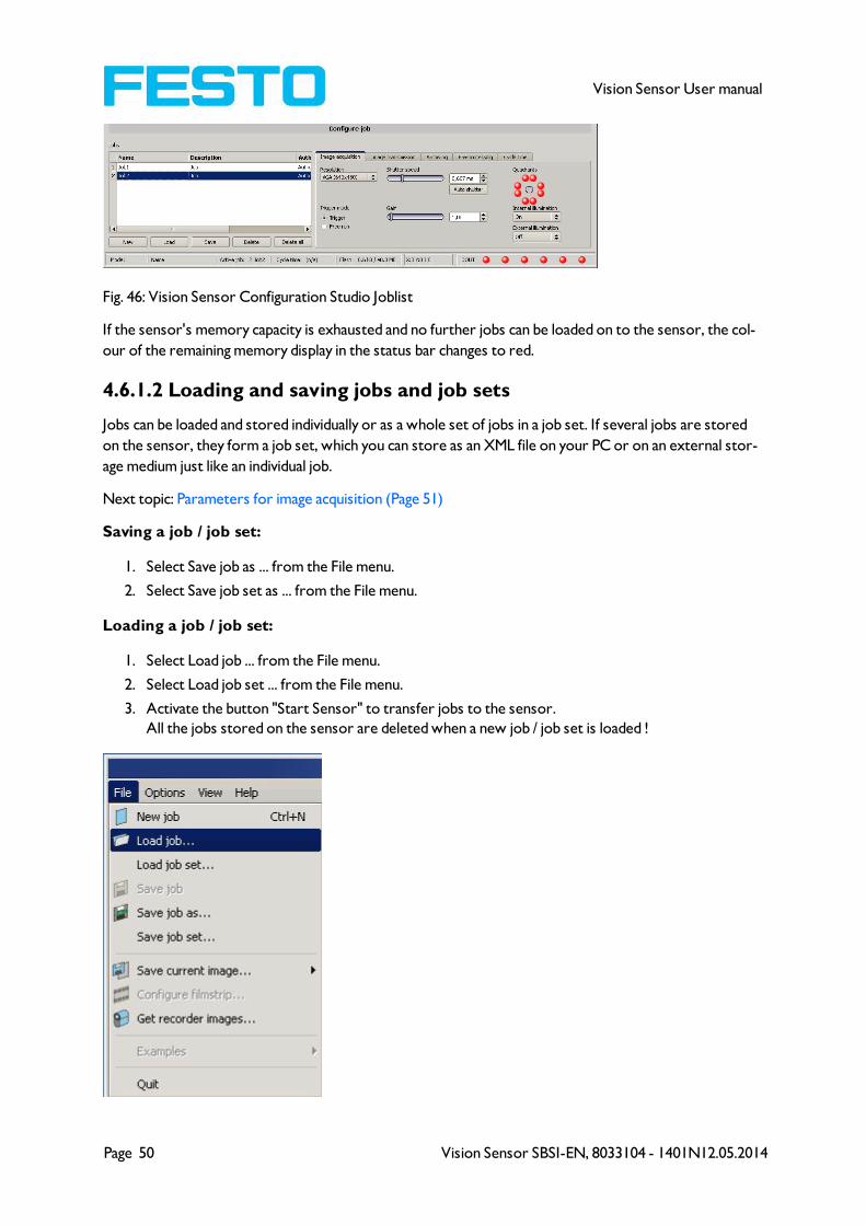
Fig. 46: Vision Sensor Configuration Studio Joblist
If the sensor's memory capacity is exhausted and no further jobs can be loaded on to the sensor, the col-
our of the remaining memory display in the status bar changes to red.
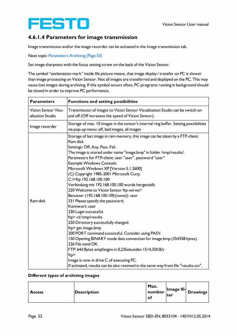
4.6.1.2 Loading and saving jobs and job sets
Jobs can be loaded and stored individually or as a whole set of jobs in a job set. If several jobs are stored
on the sensor, they form a job set, which you can store as an XML file on your PC or on an external stor-
age medium just like an individual job.
Next topic: Parameters for image acquisition (Page 51)
Saving a job / job set:
1. Select Save job as ... from the File menu.
2. Select Save job set as ... from the File menu.
Loading a job / job set:
1. Select Load job ... from the File menu.
2. Select Load job set ... from the File menu.
3. Activate the button "Start Sensor" to transfer jobs to the sensor.
All the jobs stored on the sensor are deleted when a new job / job set is loaded !

Vision Sensor SBSI-EN, 8033104 - 1401N12.05.2014 Page 51
Vision Sensor User manual
Fig. 47: Vision Sensor Configuration Studio, Load / save job
4.6.1.3 Parameters for image acquisition
The basic parameters for image acquisition are determined in the tab Image acquisition.
Next topic: Parameters for image transmission (Page 52)
Set image sharpness with the focus setting screw on the back of the Vision Sensor.
Parameters Functions and setting possibilities
Resolution
Standard resolution is VGA (640x480), but a lower resolution (QVGA) can be
selected with time-critical applications or for compatibility reasons.
Available resolutions:
R3: WVGA (736x480), VGA (640x480), QVGA (320x240), QQVGA (160x120)
When the resolution is altered, all the detectors previously defined are deleted!
Zoom Via the Zoom function different fields of view / image zones can be selected
Dynamic
Optimization of characteristics of image capturing: "Linear" means linear response
curve(behaves like Vision Sensor-products with no dynamic image capturing),
"High" means better graduation in bright areas of the image (avoids override).
Trigger mode
Select trigger mode (triggered or free run).
In case of triggered mode trigger can be done by hardware-trigger (Pin 03 WH) or
over one of the data interfaces.
In free run the Vision Sensor continuously captures images and processes eval-
uations.
Shutter speed
Parameter for control of image brightness.
Image brightness preferably should be set with “Shutter speed”, only in case that
it´s not possible to achieve the required image brightness this way use the slider
“Gain” (Default value of Gain = 1). With fast moving objects a high shutter value
can cause blurring of the image. Exposure can be set automatically with the Auto-
Shutter button. Maximum shutter value is 100ms. Maximum duration of internal
illumination pulse is 8ms. Shutter timers longer than 8 ms just make sense, if
internal and external illuminations are used.
GainSet image brightness preferably with shutter speed first, and only if necessary in a
second step with gain. (Default value of Gain = 1).
Quadrants (illu-
mination)
By click on the LED single quadrants of illumination can be switched off. This func-
tion may avoid reflections at low working distances.
Internal illumination Switch internal illumination (on, off).
External illu-
mination
Switch external illumination (on, off, permanent). External illumination is switched
over Pin 09 RD.
To obtain a continuously updated live image even without trigger, carry out the following (if necessary
temporary) settings:
l Set to free run under "Job/Image acquisition"
l Set to continuous under "Trigger / collect image"
Page 52 Vision Sensor SBSI-EN, 8033104 - 1401N12.05.2014
Vision Sensor User manual
4.6.1.4 Parameters for image transmission
Image transmission and/or the image recorder can be activated in the Image transmission tab.
Next topic: Parameters Archiving (Page 53)
Set image sharpness with the focus setting screw on the back of the Vision Sensor.
The symbol “exclamation mark” inside life picture means, that image display / transfer on PC is slower
than image processing on Vision Sensor. Not all images are transferred and displayed on the PC. This may
cause lost images during archiving. If this symbol occurs often, PC-programs running in background should
be closed in order to improve PC performance.
Parameters Functions and setting possibilities
Vision Sensor Visu-
alisation Studio
Transmission of images to Vision Sensor Visualisation Studio can be switch on
and off (Off increases the speed of Vision Sensor).
Image recorderStorage of max. 10 images in the sensor's internal ring buffer. Setting possibilities
via pop-up menu: off, bad images, all images
Ram disk
Storage of last image in ram memory, this image can be taken by a FTP-client.
Ram disk
Settings: Off, Any, Pass, Fail.
The image is stored under name "image.bmp" in folder /tmp/results/ .
Parameters for FTP-client: user "user", password "user"
Example Windows Console:
Microsoft Windows XP [Version 5.1.2600]
(C) Copyright 1985-2001 Microsoft Corp.
C:\>ftp 192.168.100.100
Verbindung mit 192.168.100.100 wurde hergestellt.
220 Welcome to Vision Sensor ftp-server!
Benutzer (192.168.100.100:(none)): user
331 Please specify the password.
Kennwort: user
230 Login successful.
ftp> cd /tmp/results
250 Directory successfully changed.
ftp> get image.bmp
200 PORT command successful. Consider using PASV.
150 Opening BINARY mode data connection for image.bmp (354358 bytes).
226 File send OK.
FTP: 64d Bytes empfangen in 0,23Sekunden 1514,35KB/s
ftp>
Image is now in drive C of executing PC.
If activated, results can be also received in the same way from file "results.csv".
Different types of archiving images
Access Description
Max.
number
of
Image fil-
terDrawings
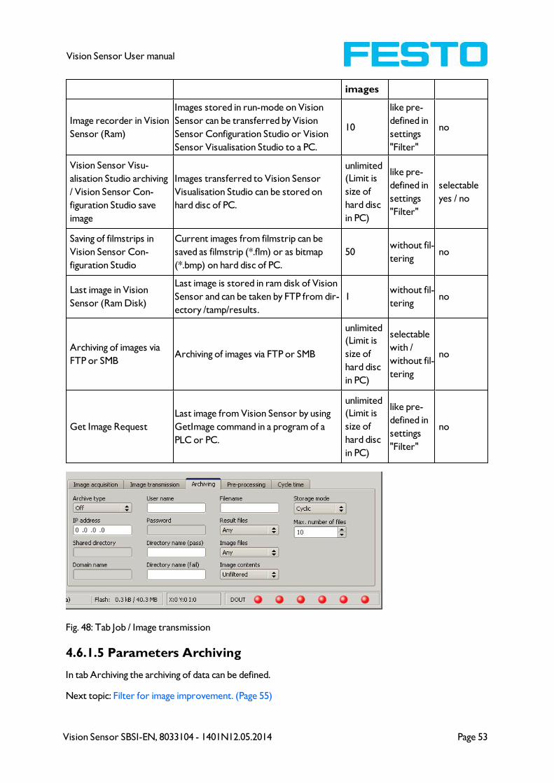
Vision Sensor SBSI-EN, 8033104 - 1401N12.05.2014 Page 53
Vision Sensor User manual
images
Image recorder in Vision
Sensor (Ram)
Images stored in run-mode on Vision
Sensor can be transferred by Vision
Sensor Configuration Studio or Vision
Sensor Visualisation Studio to a PC.
10
like pre-
defined in
settings
"Filter"
no
Vision Sensor Visu-
alisation Studio archiving
/ Vision Sensor Con-
figuration Studio save
image
Images transferred to Vision Sensor
Visualisation Studio can be stored on
hard disc of PC.
unlimited
(Limit is
size of
hard disc
in PC)
like pre-
defined in
settings
"Filter"
selectable
yes / no
Saving of filmstrips in
Vision Sensor Con-
figuration Studio
Current images from filmstrip can be
saved as filmstrip (*.flm) or as bitmap
(*.bmp) on hard disc of PC.
50without fil-
teringno
Last image in Vision
Sensor (Ram Disk)
Last image is stored in ram disk of Vision
Sensor and can be taken by FTP from dir-
ectory /tamp/results.
1without fil-
teringno
Archiving of images via
FTP or SMBArchiving of images via FTP or SMB
unlimited
(Limit is
size of
hard disc
in PC)
selectable
with /
without fil-
tering
no
Get Image Request
Last image from Vision Sensor by using
GetImage command in a program of a
PLC or PC.
unlimited
(Limit is
size of
hard disc
in PC)
like pre-
defined in
settings
"Filter"
no
Fig. 48: Tab Job / Image transmission
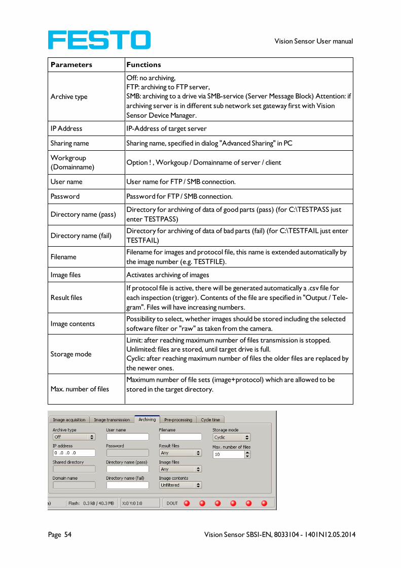
4.6.1.5 Parameters Archiving
In tab Archiving the archiving of data can be defined.
Next topic: Filter for image improvement. (Page 55)
Page 54 Vision Sensor SBSI-EN, 8033104 - 1401N12.05.2014
Vision Sensor User manual
Parameters Functions
Archive type
Off: no archiving,
FTP: archiving to FTP server,
SMB: archiving to a drive via SMB-service (Server Message Block) Attention: if
archiving server is in different sub network set gateway first with Vision
Sensor Device Manager.
IP Address IP-Address of target server
Sharing name Sharing name, specified in dialog "Advanced Sharing" in PC
Workgroup
(Domainname)Option ! , Workgoup / Domainname of server / client
User name User name for FTP / SMB connection.
Password Password for FTP / SMB connection.
Directory name (pass)Directory for archiving of data of good parts (pass) (for C:\TESTPASS just
enter TESTPASS)
Directory name (fail)Directory for archiving of data of bad parts (fail) (for C:\TESTFAIL just enter
TESTFAIL)
FilenameFilename for images and protocol file, this name is extended automatically by
the image number (e.g. TESTFILE).
Image files Activates archiving of images
Result files
If protocol file is active, there will be generated automatically a .csv file for
each inspection (trigger). Contents of the file are specified in "Output / Tele-
gram". Files will have increasing numbers.
Image contentsPossibility to select, whether images should be stored including the selected
software filter or "raw" as taken from the camera.
Storage mode
Limit: after reaching maximum number of files transmission is stopped.
Unlimited: files are stored, until target drive is full.
Cyclic: after reaching maximum number of files the older files are replaced by
the newer ones.
Max. number of files
Maximum number of file sets (image+protocol) which are allowed to be
stored in the target directory.
Vision Sensor SBSI-EN, 8033104 - 1401N12.05.2014 Page 55
Vision Sensor User manual
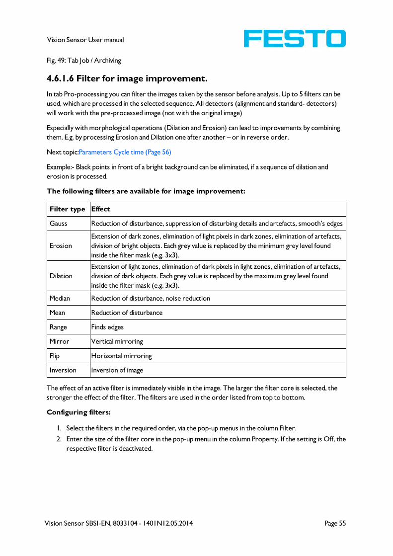
Fig. 49: Tab Job / Archiving
4.6.1.6 Filter for image improvement.
In tab Pro-processing you can filter the images taken by the sensor before analysis. Up to 5 filters can be
used, which are processed in the selected sequence. All detectors (alignment and standard- detectors)
will work with the pre-processed image (not with the original image)
Especially with morphological operations (Dilation and Erosion) can lead to improvements by combining
them. E.g. by processing Erosion and Dilation one after another – or in reverse order.
Next topic:Parameters Cycle time (Page 56)
Example:- Black points in front of a bright background can be eliminated, if a sequence of dilation and
erosion is processed.
The following filters are available for image improvement:
Filter type Effect
Gauss Reduction of disturbance, suppression of disturbing details and artefacts, smooth’s edges
Erosion
Extension of dark zones, elimination of light pixels in dark zones, elimination of artefacts,
division of bright objects. Each grey value is replaced by the minimum grey level found
inside the filter mask (e.g. 3x3).
Dilation
Extension of light zones, elimination of dark pixels in light zones, elimination of artefacts,
division of dark objects. Each grey value is replaced by the maximum grey level found
inside the filter mask (e.g. 3x3).
Median Reduction of disturbance, noise reduction
Mean Reduction of disturbance
Range Finds edges
Mirror Vertical mirroring
Flip Horizontal mirroring
Inversion Inversion of image
The effect of an active filter is immediately visible in the image. The larger the filter core is selected, the
stronger the effect of the filter. The filters are used in the order listed from top to bottom.
Configuring filters:
1. Select the filters in the required order, via the pop-up menus in the column Filter.
2. Enter the size of the filter core in the pop-up menu in the column Property. If the setting is Off, the
respective filter is deactivated.
Page 56 Vision Sensor SBSI-EN, 8033104 - 1401N12.05.2014
Vision Sensor User manual
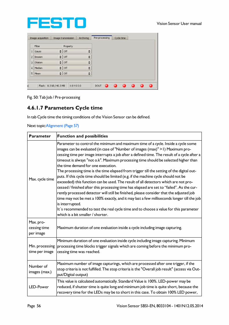
Fig. 50: Tab Job / Pre-processing
4.6.1.7 Parameters Cycle time
In tab Cycle time the timing conditions of the Vision Sensor can be defined.
Next topic:Alignment (Page 57)
Parameter Function and possibilities
Max. cycle time
Parameter to control the minimum and maximum time of a cycle. Inside a cycle some
images can be evaluated (in case of "Number of images (max)" >1) Maximum pro-
cessing time per image interrupts a job after a defined time. The result of a cycle after a
timeout is always "not o.k". Maximum processing time should be selected higher than
the time demand for one execution.
The processing time is the time elapsed from trigger till the setting of the digital out-
puts. If this cycle time should be limited (e.g. if the machine cycle should not be
exceeded) this function can be used. The result of all detectors which are not pro-
cessed / finished after this processing time has elapsed are set to “failed”. As the cur-
rently processed detector will still be finished, please consider that the adjusted job
time may not be met a 100% exactly, and it may last a few milliseconds longer till the job
is interrupted.
It´s recommended to test the real cycle time and to choose a value for this parameter
which is a bit smaller / shorter.
Max. pro-
cessing time
per image
Maximum duration of one evaluation inside a cycle including image capturing.
Min. processing
time per image
Minimum duration of one evaluation inside cycle including image capturing. Minimum
processing time blocks trigger signals which are coming before the minimum pro-
cessing time was reached.
Number of
images (max.)
Maximum number of image capturings, which are processed after one trigger, if the
stop criteria is not fulfilled. The stop criteria is the "Overall job result" (access via Out-
put/Digital output)
LED-Power
This value is calculated automatically. Standard Value is 100%. LED-power may be
reduced, if shutter time is quite long and minimum job time is quite short, because the
recovery time for the LEDs may be to short in this case. To obtain 100% LED power,
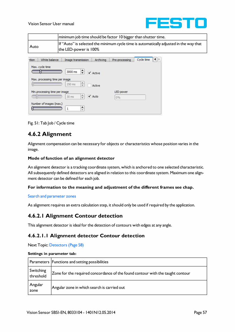
Vision Sensor SBSI-EN, 8033104 - 1401N12.05.2014 Page 57
Vision Sensor User manual
minimum job time should be factor 10 bigger than shutter time.
AutoIf “Auto” is selected the minimum cycle time is automatically adjusted in the way that
the LED-power is 100%
Fig. 51: Tab Job / Cycle time
4.6.2 Alignment
Alignment compensation can be necessary for objects or characteristics whose position varies in the
image.
Mode of function of an alignment detector
An alignment detector is a tracking coordinate system, which is anchored to one selected characteristic.
All subsequently defined detectors are aligned in relation to this coordinate system. Maximum one align-
ment detector can be defined for each job.
For information to the meaning and adjustment of the different frames see chap.
Search and parameter zones
As alignment requires an extra calculation step, it should only be used if required by the application.
4.6.2.1 Alignment Contour detection
This alignment detector is ideal for the detection of contours with edges at any angle.
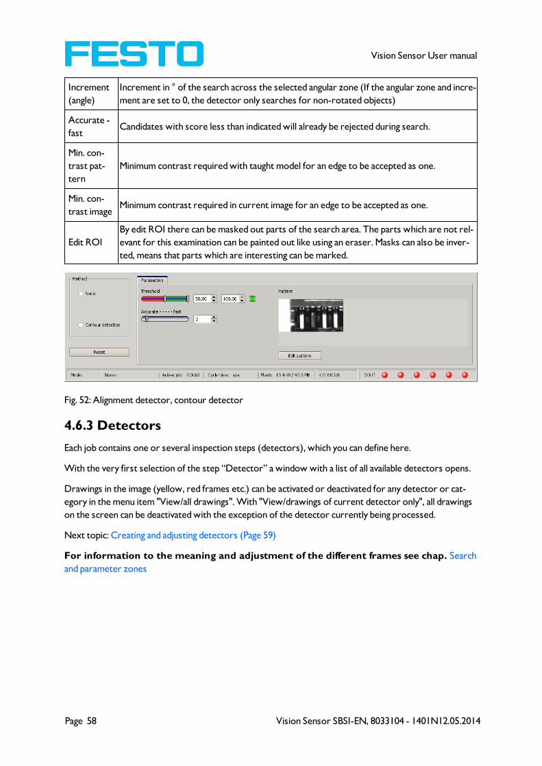
4.6.2.1.1 Alignment detector Contour detection
Next Topic: Detectors (Page 58)
Settings in parameter tab:
Parameters Functions and setting possibilities
Switching
thresholdZone for the required concordance of the found contour with the taught contour
Angular
zoneAngular zone in which search is carried out
Page 58 Vision Sensor SBSI-EN, 8033104 - 1401N12.05.2014
Vision Sensor User manual
Increment
(angle)
Increment in ° of the search across the selected angular zone (If the angular zone and incre-
ment are set to 0, the detector only searches for non-rotated objects)
Accurate -
fastCandidates with score less than indicated will already be rejected during search.
Min. con-
trast pat-
tern
Minimum contrast required with taught model for an edge to be accepted as one.
Min. con-
trast imageMinimum contrast required in current image for an edge to be accepted as one.
Edit ROI
By edit ROI there can be masked out parts of the search area. The parts which are not rel-
evant for this examination can be painted out like using an eraser. Masks can also be inver-
ted, means that parts which are interesting can be marked.
Fig. 52: Alignment detector, contour detector
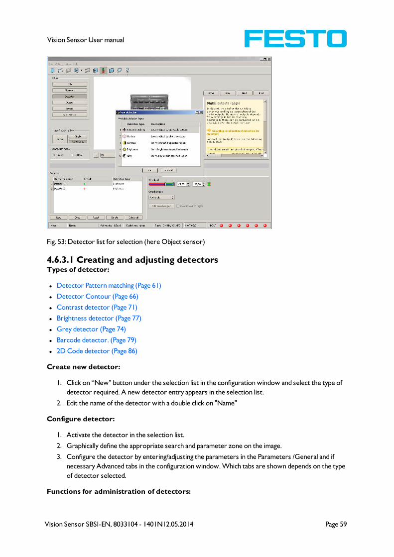
4.6.3 Detectors
Each job contains one or several inspection steps (detectors), which you can define here.
With the very first selection of the step “Detector” a window with a list of all available detectors opens.
Drawings in the image (yellow, red frames etc.) can be activated or deactivated for any detector or cat-
egory in the menu item "View/all drawings". With "View/drawings of current detector only", all drawings
on the screen can be deactivated with the exception of the detector currently being processed.
Next topic: Creating and adjusting detectors (Page 59)
For information to the meaning and adjustment of the different frames see chap. Search
and parameter zones
Vision Sensor SBSI-EN, 8033104 - 1401N12.05.2014 Page 59
Vision Sensor User manual
Fig. 53: Detector list for selection (here Object sensor)
4.6.3.1 Creating and adjusting detectorsTypes of detector:
l Detector Pattern matching (Page 61)
l Detector Contour (Page 66)
l Contrast detector (Page 71)
l Brightness detector (Page 77)
l Grey detector (Page 74)
l Barcode detector. (Page 79)
l 2D Code detector (Page 86)
Create new detector:
1. Click on “New" button under the selection list in the configuration window and select the type of
detector required. A new detector entry appears in the selection list.
2. Edit the name of the detector with a double click on "Name"
Configure detector:
1. Activate the detector in the selection list.
2. Graphically define the appropriate search and parameter zone on the image.
3. Configure the detector by entering/adjusting the parameters in the Parameters /General and if
necessary Advanced tabs in the configuration window. Which tabs are shown depends on the type
of detector selected.
Functions for administration of detectors:

Page 60 Vision Sensor SBSI-EN, 8033104 - 1401N12.05.2014
Vision Sensor User manual
Control
panelFunctions
New Adds new detector > dialogue box with above-mentioned detector selection list appears
Copy
Copies all parameters from one detector to one or several others. The parameter zones
are not copied. All detectors must be from the same type.
Copy process:
Create all desired destination detectors; they must be of the same type as the source
detector.
Mark source detector in the list
Click to button „copy“
A list occurs, mark all desired destination detectors. (To select several press “Ctrl” key)
Click “Copy” to confirm
Reset Resets parameters and search and parameter zones of selected detector to standard values
Delete Deletes the selected detector
Delete all Deletes all the detectors in the list
Information:
"Flash x.x/yyyy.y kB" appears in the bottom corner of the screen, indicating first the memory used by the
current configuration x.x), and the memory available on the sensor (yyyy.y) in kB. Should the memory
used exceed the available memory, this indicator switches to red as there is not enough space for the cur-
rent settings on the sensor. In this case you can delete other jobs from the sensor before transfer.
Drawings in the image (yellow, red frames etc.) can be activated or deactivated for any detector or cat-
egory in the menu item "View/all drawings". With "View/drawings of current detector only", all drawings
on the screen can be deactivated with the exception of the detector currently being processed.
4.6.3.2 Selecting a suitable detector
Next topic: Detector Pattern matching (Page 61)
The following detectors are available in Vision Sensor Configuration Studio:
Object sensor
Type of detectors Description
Pattern matching Part detection using pattern matching, X- and Y- translational
Contour detection Part detection using object contour, up to 360° rotation
Contrast Evaluation of contrast in selected search zone
Brightness Evaluation of brightness in selected search zone
Grey level Evaluation of grey values in selected search zone
Code Reader

Vision Sensor SBSI-EN, 8033104 - 1401N12.05.2014 Page 61
Vision Sensor User manual
Type of detectors Description
Barcode Barcode reading 1D Codes (Code reader)
2D- Code Data code reading 2D Codes (Code reader)
4.6.3.3 Detector Pattern matching
This detector is suitable for the detection of patterns of any shape, even without distinctive edges or con-
tours.
Fig. 54: Detector Pattern matching
Next topic: Detector Contour (Page 66)
Pattern matching application (Page 62)
4.6.3.3.1 Settings in tab Basic:
Parameters Functions
Switching
threshold
min/max
Zone for the required concordance of the pattern found with the pattern taught.
Accurate -
fast
Number of search levels / coarsening levels.
0 = automatic selection
Higher value: faster = riskier (overlook candidates)
Smaller value: slower = less risky (all candidates)
Position
check
Checks whether the pattern found is in the right position. If position check is activated,
the position frame is shown in blue (either rectangular or elliptic).
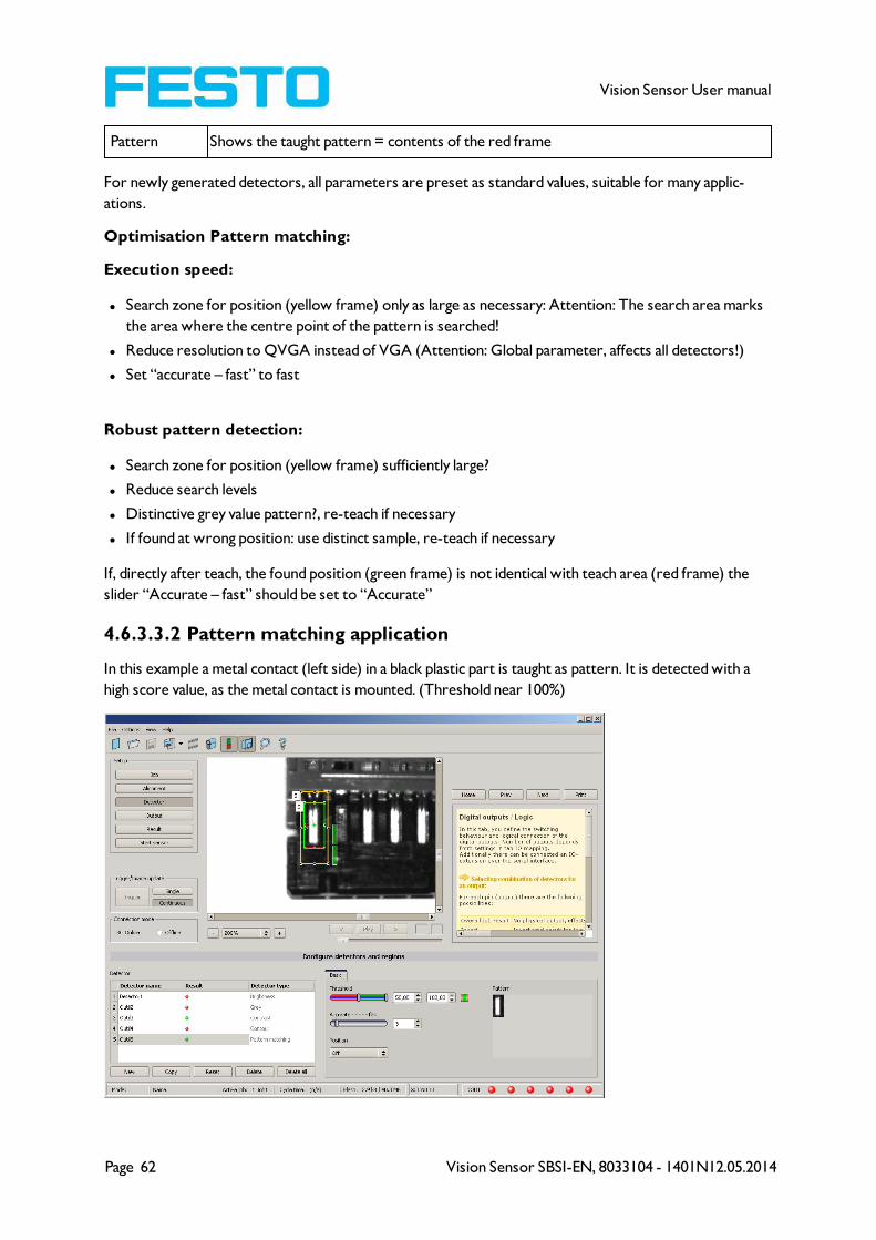
Page 62 Vision Sensor SBSI-EN, 8033104 - 1401N12.05.2014
Vision Sensor User manual
Pattern Shows the taught pattern = contents of the red frame
For newly generated detectors, all parameters are preset as standard values, suitable for many applic-
ations.
Optimisation Pattern matching:
Execution speed:
l Search zone for position (yellow frame) only as large as necessary: Attention: The search area marks
the area where the centre point of the pattern is searched!
l Reduce resolution to QVGA instead of VGA (Attention: Global parameter, affects all detectors!)
l Set “accurate – fast” to fast
Robust pattern detection:
l Search zone for position (yellow frame) sufficiently large?
l Reduce search levels
l Distinctive grey value pattern?, re-teach if necessary
l If found at wrong position: use distinct sample, re-teach if necessary
If, directly after teach, the found position (green frame) is not identical with teach area (red frame) the
slider “Accurate – fast” should be set to “Accurate”
4.6.3.3.2 Pattern matching application
In this example a metal contact (left side) in a black plastic part is taught as pattern. It is detected with a
high score value, as the metal contact is mounted. (Threshold near 100%)
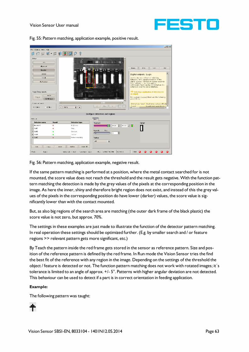
Vision Sensor SBSI-EN, 8033104 - 1401N12.05.2014 Page 63
Vision Sensor User manual
Fig. 55: Pattern matching, application example, positive result.
Fig. 56: Pattern matching, application example, negative result.
If the same pattern matching is performed at a position, where the metal contact searched for is not
mounted, the score value does not reach the threshold and the result gets negative. With the function pat-
tern matching the detection is made by the grey values of the pixels at the corresponding position in the
image. As here the inner, shiny and therefore bright region does not exist, and instead of this the grey val-
ues of the pixels in the corresponding position do have lower (darker) values, the score value is sig-
nificantly lower than with the contact mounted.
But, as also big regions of the search area are matching (the outer dark frame of the black plastic) the
score value is not zero, but approx. 70%.
The settings in these examples are just made to illustrate the function of the detector pattern matching.
In real operation these settings should be optimized further. (E.g. by smaller search and / or feature
regions >> relevant pattern gets more significant, etc.)
By Teach the pattern inside the red frame gets stored in the sensor as reference pattern. Size and pos-
ition of the reference pattern is defined by the red frame. In Run mode the Vision Sensor tries the find
the best fit of the reference with any region in the image. Depending on the settings of the threshold the
object / feature is detected or not. The function pattern matching does not work with rotated images; it´s
tolerance is limited to an angle of approx. +/- 5°. Patterns with higher angular deviation are not detected.
This behaviour can be used to detect if a part is in correct orientation in feeding application.
Example:
The following pattern was taught:
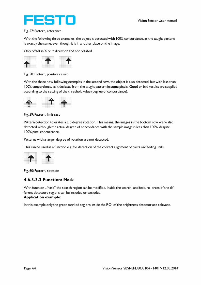
Page 64 Vision Sensor SBSI-EN, 8033104 - 1401N12.05.2014
Vision Sensor User manual
Fig. 57: Pattern, reference
With the following three examples, the object is detected with 100% concordance, as the taught pattern
is exactly the same, even though it is in another place on the image.
Only offset in X or Y direction and not rotated.
Fig. 58: Pattern, positive result
With the three now following examples in the second row, the object is also detected, but with less than
100% concordance, as it deviates from the taught pattern in some pixels. Good or bad results are supplied
according to the setting of the threshold value (degree of concordance).
Fig. 59: Pattern, limit case
Pattern detection tolerates a ± 5 degree rotation. This means, the images in the bottom row were also
detected, although the actual degree of concordance with the sample image is less than 100%, despite
100% pixel concordance.
Patterns with a larger degree of rotation are not detected.
This can be used as a function e.g. for detection of the correct alignment of parts on feeding units.
Fig. 60: Pattern, rotation
4.6.3.3.3 Function: Mask
With function „Mask“ the search region can be modified. Inside the search- and feature- areas of the dif-
ferent detectors regions can be included or excluded.
Application example:
In this example only the green marked regions inside the ROI of the brightness detector are relevant.
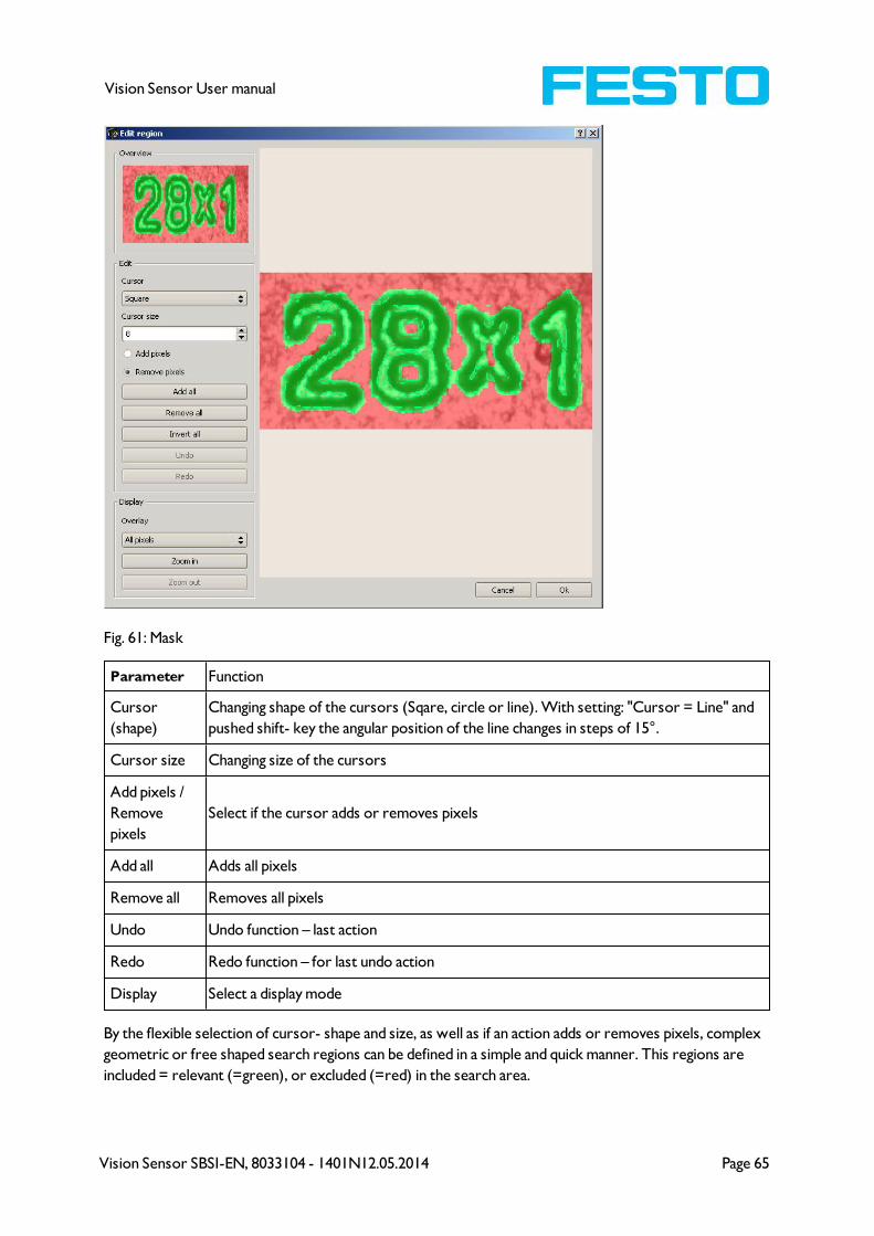
Vision Sensor SBSI-EN, 8033104 - 1401N12.05.2014 Page 65
Vision Sensor User manual
Fig. 61: Mask
Parameter Function
Cursor
(shape)
Changing shape of the cursors (Sqare, circle or line). With setting: "Cursor = Line" and
pushed shift- key the angular position of the line changes in steps of 15°.
Cursor size Changing size of the cursors
Add pixels /
Remove
pixels
Select if the cursor adds or removes pixels
Add all Adds all pixels
Remove all Removes all pixels
Undo Undo function – last action
Redo Redo function – for last undo action
Display Select a display mode
By the flexible selection of cursor- shape and size, as well as if an action adds or removes pixels, complex
geometric or free shaped search regions can be defined in a simple and quick manner. This regions are
included = relevant (=green), or excluded (=red) in the search area.

Page 66 Vision Sensor SBSI-EN, 8033104 - 1401N12.05.2014
Vision Sensor User manual
To use the function „Mask” the following settings are necessary for the different
detector types
Detector type Necessary setting to use the function „Mask“
Pattern matching Generally possible with „Edit pattern”
Contour Generally possible with „Edit contour”
Contrast Search region „Free shape“
Brightness Search region „Free shape“
Grey Search region „Free shape“
4.6.3.4 Detector Contour
This detector is suitable for detection of samples from edges at any angle.
Next Topic:Contrast detector (Page 71)
Settings in Scaling tab: (Page 69)
Settings in Angle tab: (Page 69)
Contour application: (Page 70)
Function: Mask (Page 64)
The contours of an object in the search area are taught and stored in the sensor. In Run mode the sensor
searches the position of the best fit with the taught contour. If the fit is higher than the selected threshold
the result is positive. The function contour detection can work incomplete 360° angular detection mode.
So the object can be rotated in any angle. The angular settings must be set accordingly.

Vision Sensor SBSI-EN, 8033104 - 1401N12.05.2014 Page 67
Vision Sensor User manual
Fig. 62: Detector contour, tab pattern
The in the below, right corner in pale blue shown edges (high contrast changes in the image) have been
identified and drawn because of the before made parameter settings. The found edges / contour can be
influenced by changing these parameters, or by the function “Edit contour”. The Vision Sensor now
searches this contour in the search area (yellow frame).
4.6.3.4.1 Settings in tab pattern:
Parameters Functions
Threshold
Min/MaxZone for required concordance of found contour with taught contour.
Min. contrast
patternMinimum contrast required with taught model for an edge to be detected as one.
Min. contrast
imageMinimum contrast required in current image for an edge to be accepted as one.
Position check
Checks whether the sample found is in the right position.
If position check is activated, the authorised zone for the position of the found para-
meter is shown in a blue frame (either rectangular or elliptic). The centre (green
cross) of the parameter found must be situated inside the blue frame.
Pattern Taught sample with display of the edges found
Edit contour
By edit contour there can be masked out parts of the search area. The parts which
are not relevant for this examination can be painted out like using an eraser. Masks
can also be inverted, means that parts which are interesting can be marked. S. also
chap.
Page 68 Vision Sensor SBSI-EN, 8033104 - 1401N12.05.2014
Vision Sensor User manual
For newly generated detectors, all parameters are preset as standard values, suitable for many applic-
ations.
Optimisation:
Execution speed:
l Search zone for position (yellow frame) only as large as necessary. Please note: The contour is found
as long as the centre point of the pattern is inside the search area!
l Search zone for angle only as large as necessary
l Search zone for scale only as large as necessary
l Reduce resolution to CGA instead of VGA (Attention: Global parameter, affects all detectors!)
l Set “accurate – fast” to fast
l Increase value “Min. contrast pattern”. Take care that the relevant contours are still visible in the dis-
play.
l Increase value “Min. contrast Image”.
l Especially in case of alignment: Use alternate reference pattern. E.g. with higher contrast, that “Min.
contrast pattern” and Min. contrast image” can be increased.
Robust detection:
l Search zone for position (yellow frame) sufficiently large?
l Search zone for angle sufficiently large?
l Search zone for scale sufficiently large?
l Contrasts for model and image suitably set? (for model visible in sample)
l Set “accurate – fast” to accurate
l Are there some and overlapping objects in the image?
l Distinctive edges available?, re-teach if necessary
l “Min. contrast pattern” set to a suitable value? If in the taught pattern the relevant contour lines are
not shown completely: decrease “Min. contrast pattern”. If there are too many contour lines shown:
increase “Min. contrast pattern”.
l “Min. contrast image” set to a suitable value for the current image? If the current image(s) do have a
higher / lower contrast than the taught reference image /pattern please increase / decrease the value
of “Min. contrast image” accordingly.
l In the taught pattern the relevant contour lines are not shown completely: decrease “Min. contrast
pattern”. If there are too many contour lines shown: increase “Min. contrast pattern”.
l If found at wrong position: use distinct sample, re-teach if necessary
l If the result value is fluctuating strongly from image to image? Take care that there are no “false
edges” taught (edges because of shadows, or fragments of contours, which are not desired in the con-
tour model): This can be achieved by increasing “Min. contrast pattern” or by eliminating those false
edges by function “Edit contour”.
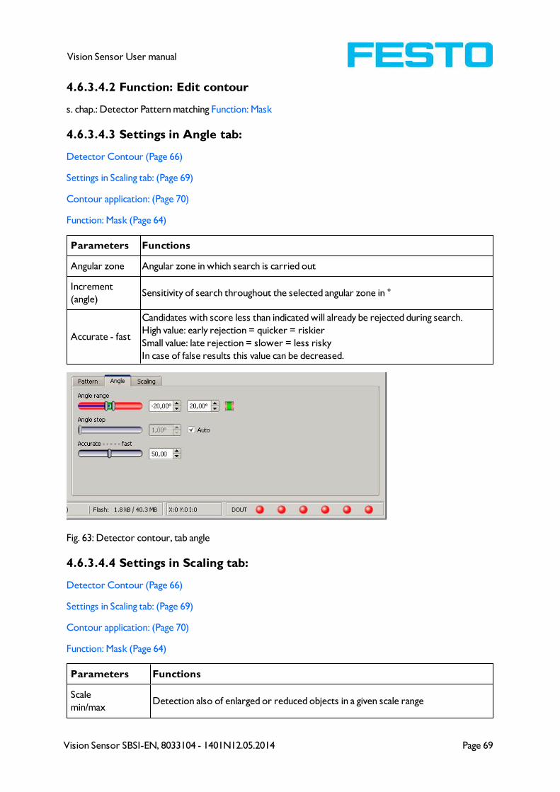
Vision Sensor SBSI-EN, 8033104 - 1401N12.05.2014 Page 69
Vision Sensor User manual
4.6.3.4.2 Function: Edit contour
s. chap.: Detector Pattern matching Function: Mask
4.6.3.4.3 Settings in Angle tab:
Detector Contour (Page 66)
Settings in Scaling tab: (Page 69)
Contour application: (Page 70)
Function: Mask (Page 64)
Parameters Functions
Angular zone Angular zone in which search is carried out
Increment
(angle)Sensitivity of search throughout the selected angular zone in °
Accurate - fast
Candidates with score less than indicated will already be rejected during search.
High value: early rejection = quicker = riskier
Small value: late rejection = slower = less risky
In case of false results this value can be decreased.
Fig. 63: Detector contour, tab angle
4.6.3.4.4 Settings in Scaling tab:
Detector Contour (Page 66)
Settings in Scaling tab: (Page 69)
Contour application: (Page 70)
Function: Mask (Page 64)
Parameters Functions
Scale
min/maxDetection also of enlarged or reduced objects in a given scale range
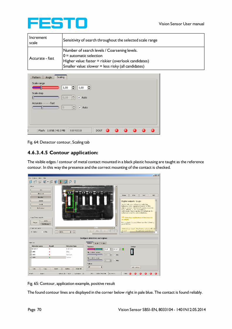
Page 70 Vision Sensor SBSI-EN, 8033104 - 1401N12.05.2014
Vision Sensor User manual
Increment
scaleSensitivity of search throughout the selected scale range
Accurate - fast
Number of search levels / Coarsening levels.
0 = automatic selection
Higher value: faster = riskier (overlook candidates)
Smaller value: slower = less risky (all candidates)
Fig. 64: Detector contour, Scaling tab
4.6.3.4.5 Contour application:
The visible edges / contour of metal contact mounted in a black plastic housing are taught as the reference
contour. In this way the presence and the correct mounting of the contact is checked.
Fig. 65: Contour, application example, positive result
The found contour lines are displayed in the corner below right in pale blue. The contact is found reliably.
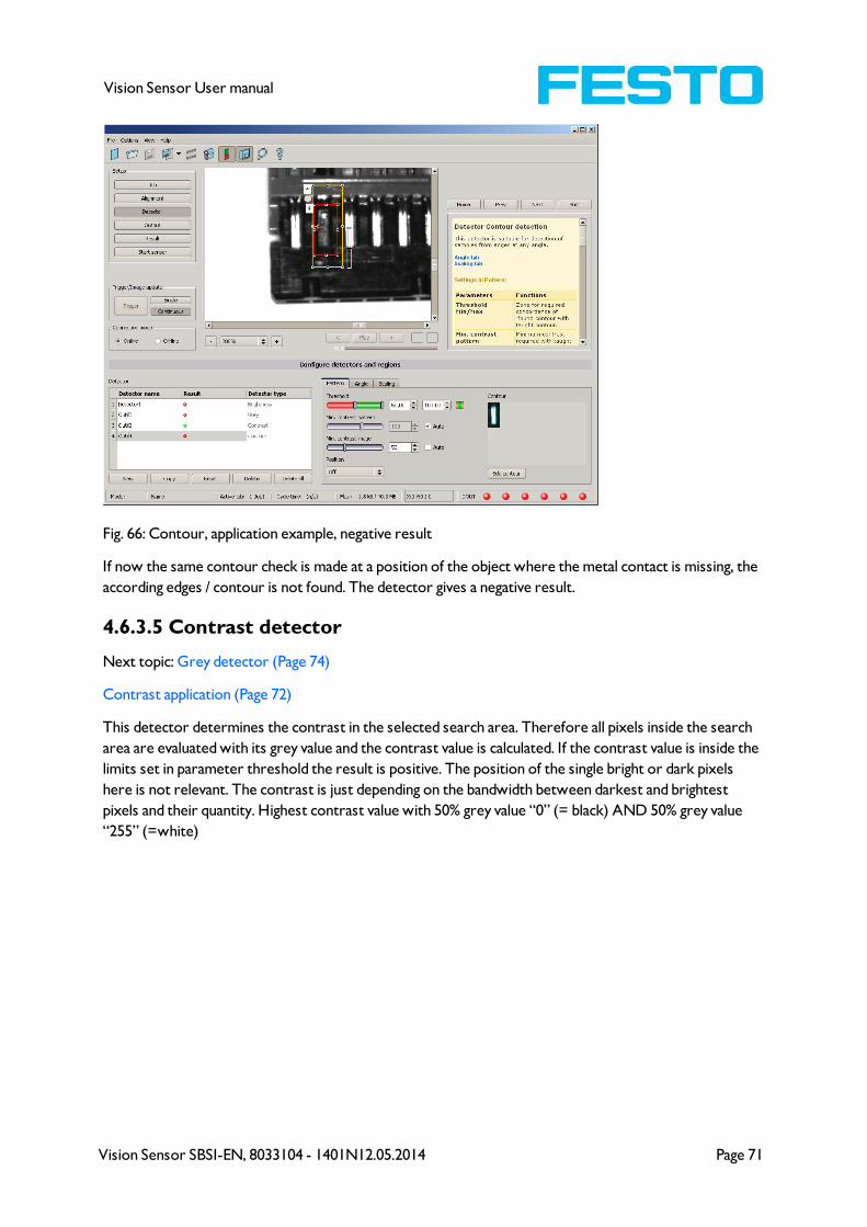
Vision Sensor SBSI-EN, 8033104 - 1401N12.05.2014 Page 71
Vision Sensor User manual
Fig. 66: Contour, application example, negative result
If now the same contour check is made at a position of the object where the metal contact is missing, the
according edges / contour is not found. The detector gives a negative result.
4.6.3.5 Contrast detector
Next topic: Grey detector (Page 74)
Contrast application (Page 72)
This detector determines the contrast in the selected search area. Therefore all pixels inside the search
area are evaluated with its grey value and the contrast value is calculated. If the contrast value is inside the
limits set in parameter threshold the result is positive. The position of the single bright or dark pixels
here is not relevant. The contrast is just depending on the bandwidth between darkest and brightest
pixels and their quantity. Highest contrast value with 50% grey value “0” (= black) AND 50% grey value
“255” (=white)
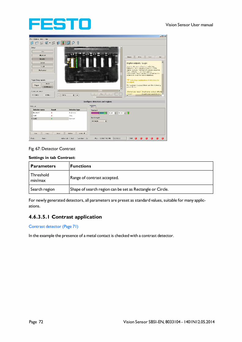
Page 72 Vision Sensor SBSI-EN, 8033104 - 1401N12.05.2014
Vision Sensor User manual
Fig. 67: Detector Contrast
Settings in tab Contrast:
Parameters Functions
Threshold
min/maxRange of contrast accepted.
Search region Shape of search region can be set as Rectangle or Circle.
For newly generated detectors, all parameters are preset as standard values, suitable for many applic-
ations.
4.6.3.5.1 Contrast application
Contrast detector (Page 71)
In the example the presence of a metal contact is checked with a contrast detector.

Vision Sensor SBSI-EN, 8033104 - 1401N12.05.2014 Page 73
Vision Sensor User manual
Fig. 68: Contrast, application example, positive result.
The presence of a shiny metal contact, in the middle of a surrounding black plastic housing, is checked with
a contrast detector. As in this configuration contrast is pretty high the contrast detector delivers a high
score, and in combination with alignment the whole job works reliably.
Fig. 69: Contrast, application example, negative result
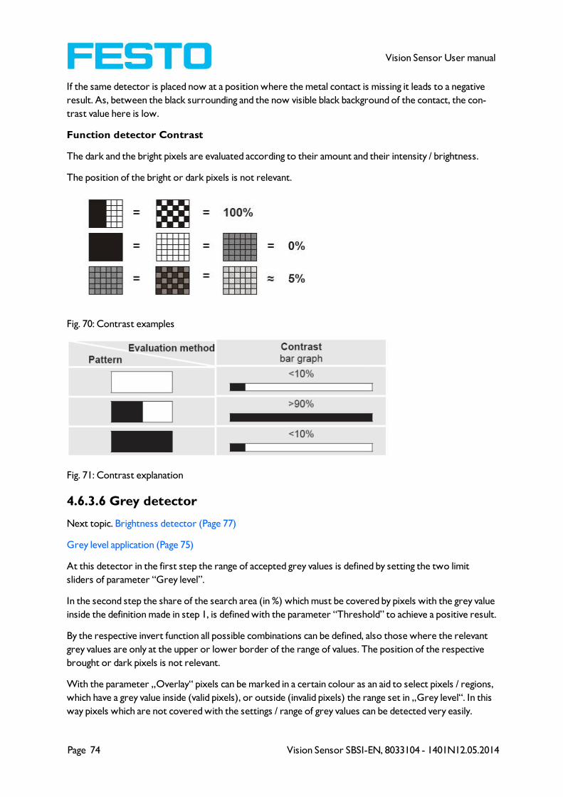
Page 74 Vision Sensor SBSI-EN, 8033104 - 1401N12.05.2014
Vision Sensor User manual
If the same detector is placed now at a position where the metal contact is missing it leads to a negative
result. As, between the black surrounding and the now visible black background of the contact, the con-
trast value here is low.
Function detector Contrast
The dark and the bright pixels are evaluated according to their amount and their intensity / brightness.
The position of the bright or dark pixels is not relevant.
Fig. 70: Contrast examples
Fig. 71: Contrast explanation
4.6.3.6 Grey detector
Next topic. Brightness detector (Page 77)
Grey level application (Page 75)
At this detector in the first step the range of accepted grey values is defined by setting the two limit
sliders of parameter “Grey level”.
In the second step the share of the search area (in %) which must be covered by pixels with the grey value
inside the definition made in step 1, is defined with the parameter “Threshold” to achieve a positive result.
By the respective invert function all possible combinations can be defined, also those where the relevant
grey values are only at the upper or lower border of the range of values. The position of the respective
brought or dark pixels is not relevant.
With the parameter „Overlay“ pixels can be marked in a certain colour as an aid to select pixels / regions,
which have a grey value inside (valid pixels), or outside (invalid pixels) the range set in „Grey level“. In this
way pixels which are not covered with the settings / range of grey values can be detected very easily.
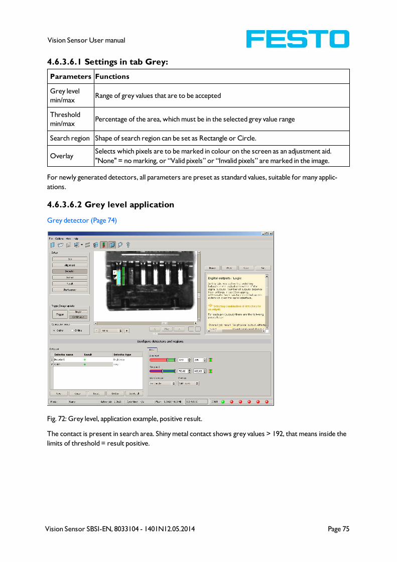
Vision Sensor SBSI-EN, 8033104 - 1401N12.05.2014 Page 75
Vision Sensor User manual
4.6.3.6.1 Settings in tab Grey:
Parameters Functions
Grey level
min/maxRange of grey values that are to be accepted
Threshold
min/maxPercentage of the area, which must be in the selected grey value range
Search region Shape of search region can be set as Rectangle or Circle.
OverlaySelects which pixels are to be marked in colour on the screen as an adjustment aid.
"None" = no marking, or “Valid pixels” or “Invalid pixels” are marked in the image.
For newly generated detectors, all parameters are preset as standard values, suitable for many applic-
ations.
4.6.3.6.2 Grey level application
Grey detector (Page 74)
Fig. 72: Grey level, application example, positive result.
The contact is present in search area. Shiny metal contact shows grey values > 192, that means inside the
limits of threshold = result positive.
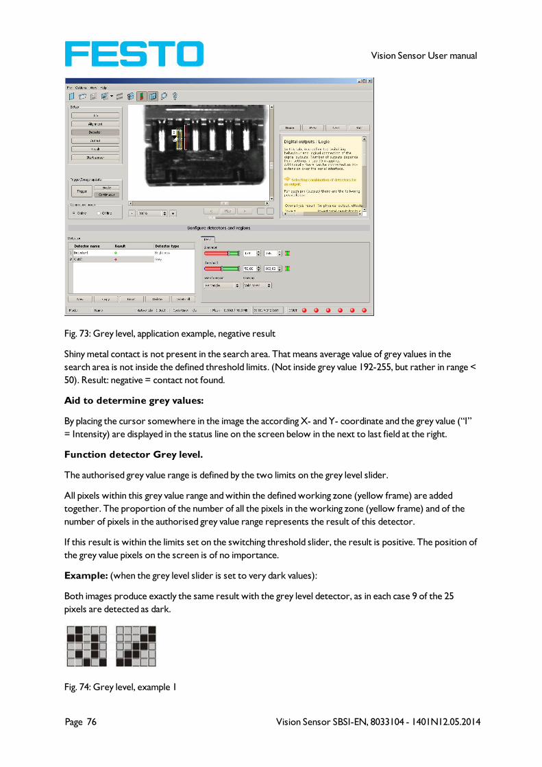
Page 76 Vision Sensor SBSI-EN, 8033104 - 1401N12.05.2014
Vision Sensor User manual
Fig. 73: Grey level, application example, negative result
Shiny metal contact is not present in the search area. That means average value of grey values in the
search area is not inside the defined threshold limits. (Not inside grey value 192-255, but rather in range <
50). Result: negative = contact not found.
Aid to determine grey values:
By placing the cursor somewhere in the image the according X- and Y- coordinate and the grey value (“I”
= Intensity) are displayed in the status line on the screen below in the next to last field at the right.
Function detector Grey level.
The authorised grey value range is defined by the two limits on the grey level slider.
All pixels within this grey value range and within the defined working zone (yellow frame) are added
together. The proportion of the number of all the pixels in the working zone (yellow frame) and of the
number of pixels in the authorised grey value range represents the result of this detector.
If this result is within the limits set on the switching threshold slider, the result is positive. The position of
the grey value pixels on the screen is of no importance.
Example: (when the grey level slider is set to very dark values):
Both images produce exactly the same result with the grey level detector, as in each case 9 of the 25
pixels are detected as dark.
Fig. 74: Grey level, example 1
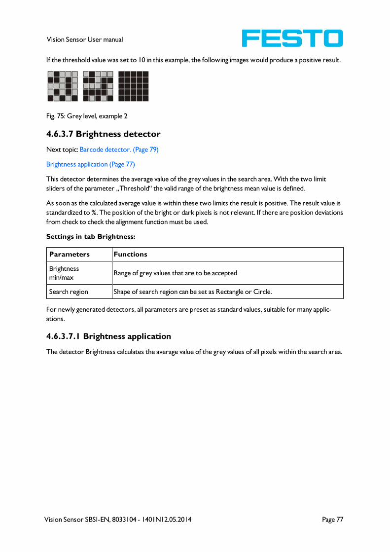
Vision Sensor SBSI-EN, 8033104 - 1401N12.05.2014 Page 77
Vision Sensor User manual
If the threshold value was set to 10 in this example, the following images would produce a positive result.
Fig. 75: Grey level, example 2
4.6.3.7 Brightness detector
Next topic: Barcode detector. (Page 79)
Brightness application (Page 77)
This detector determines the average value of the grey values in the search area. With the two limit
sliders of the parameter „Threshold“ the valid range of the brightness mean value is defined.
As soon as the calculated average value is within these two limits the result is positive. The result value is
standardized to %. The position of the bright or dark pixels is not relevant. If there are position deviations
from check to check the alignment function must be used.
Settings in tab Brightness:
Parameters Functions
Brightness
min/maxRange of grey values that are to be accepted
Search region Shape of search region can be set as Rectangle or Circle.
For newly generated detectors, all parameters are preset as standard values, suitable for many applic-
ations.
4.6.3.7.1 Brightness application
The detector Brightness calculates the average value of the grey values of all pixels within the search area.

Page 78 Vision Sensor SBSI-EN, 8033104 - 1401N12.05.2014
Vision Sensor User manual
Fig. 76: Brightness, application example, positive result.
The contact is present within the position searched for; therefore the average value of the grey values in
the search area has a high score (near 100%). That means the current value is within the requested
threshold limits and the result is positive = contact present.
Fig. 77: Brightness, application example, negative result.
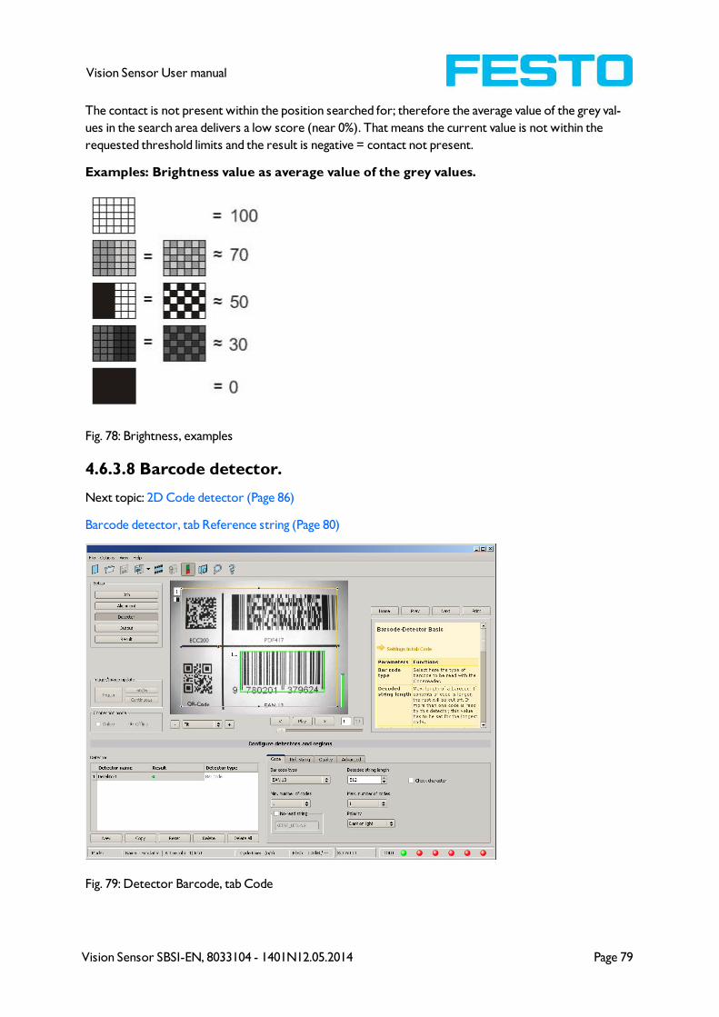
Vision Sensor SBSI-EN, 8033104 - 1401N12.05.2014 Page 79
Vision Sensor User manual
The contact is not present within the position searched for; therefore the average value of the grey val-
ues in the search area delivers a low score (near 0%). That means the current value is not within the
requested threshold limits and the result is negative = contact not present.
Examples: Brightness value as average value of the grey values.
Fig. 78: Brightness, examples
4.6.3.8 Barcode detector.
Next topic: 2D Code detector (Page 86)
Barcode detector, tab Reference string (Page 80)
Fig. 79: Detector Barcode, tab Code
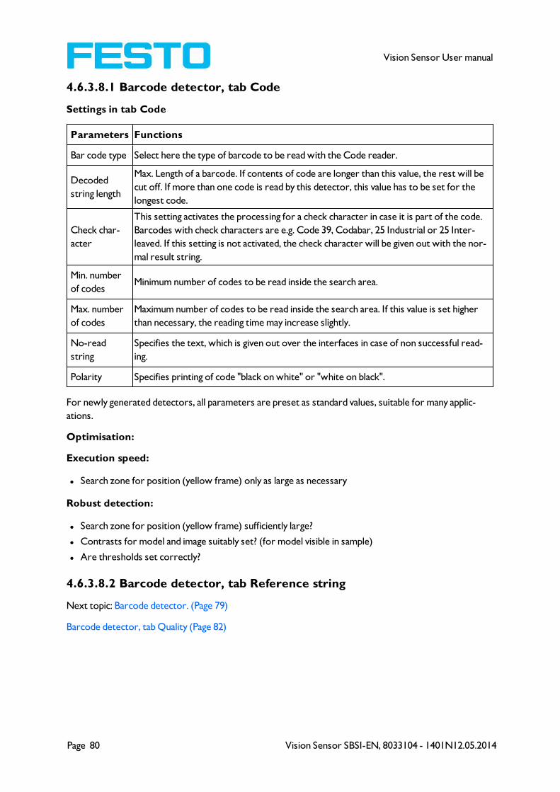
Page 80 Vision Sensor SBSI-EN, 8033104 - 1401N12.05.2014
Vision Sensor User manual
4.6.3.8.1 Barcode detector, tab Code
Settings in tab Code
Parameters Functions
Bar code type Select here the type of barcode to be read with the Code reader.
Decoded
string length
Max. Length of a barcode. If contents of code are longer than this value, the rest will be
cut off. If more than one code is read by this detector, this value has to be set for the
longest code.
Check char-
acter
This setting activates the processing for a check character in case it is part of the code.
Barcodes with check characters are e.g. Code 39, Codabar, 25 Industrial or 25 Inter-
leaved. If this setting is not activated, the check character will be given out with the nor-
mal result string.
Min. number
of codesMinimum number of codes to be read inside the search area.
Max. number
of codes
Maximum number of codes to be read inside the search area. If this value is set higher
than necessary, the reading time may increase slightly.
No-read
string
Specifies the text, which is given out over the interfaces in case of non successful read-
ing.
Polarity Specifies printing of code "black on white" or "white on black".
For newly generated detectors, all parameters are preset as standard values, suitable for many applic-
ations.
Optimisation:
Execution speed:
l Search zone for position (yellow frame) only as large as necessary
Robust detection:
l Search zone for position (yellow frame) sufficiently large?
l Contrasts for model and image suitably set? (for model visible in sample)
l Are thresholds set correctly?
4.6.3.8.2 Barcode detector, tab Reference string
Next topic: Barcode detector. (Page 79)
Barcode detector, tab Quality (Page 82)

Vision Sensor SBSI-EN, 8033104 - 1401N12.05.2014 Page 81
Vision Sensor User manual
Fig. 80: Detector Barcode, tab Reference string
Settings in tab Reference String
Parameters Functions
Compare
string
Activates verification of contents of the result information. The verification is done by
using of regular expressions.
Ref. stringThis text or regular expression is taken for verification. Here can be entered characters
or regular expressions.
Add expres-
sionOpens a list with examples for regular expressions.
Teach ref.
string
Reads the code under the code reader and takes the contents of this code as a ref-
erence string. This text can be changed later.
For newly generated detectors, all parameters are preset as standard values, suitable for many applic-
ations.
Examples for reference strings specified by regular expressions:
Reference string Hit Example for hit
123 String containing 123 01234
\A123 String beginning with 123 1234
123\Z String ending by 123 0123
\A123\Z String matching exactly 123 123
[123] String containing one of the characters 33
[123]{2} String containing sequence of the characters of length 2 23
[12]|[34] String containing a character of one of both groups 4
Most important elements of regular expressions:
^ or \AMatches start of string
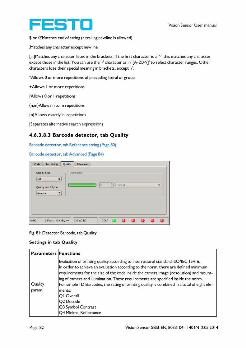
Page 82 Vision Sensor SBSI-EN, 8033104 - 1401N12.05.2014
Vision Sensor User manual
$ or \ZMatches end of string (a trailing newline is allowed)
.Matches any character except newline
[...]Matches any character listed in the brackets. If the first character is a '^', this matches any character
except those in the list. You can use the '-' character as in '[A-Z0-9]' to select character ranges. Other
characters lose their special meaning in brackets, except '\'.
*Allows 0 or more repetitions of preceding literal or group
+Allows 1 or more repetitions
?Allows 0 or 1 repetitions
{n,m}Allows n to m repetitions
{n}Allows exactly 'n' repetitions
|Separates alternative search expressions
4.6.3.8.3 Barcode detector, tab Quality
Barcode detector, tab Reference string (Page 80)
Barcode detector, tab Advanced (Page 84)
Fig. 81: Detector Barcode, tab Quality
Settings in tab Quality
Parameters Functions
Quality
param.
Evaluation of printing quality according to international standard ISO/IEC 15416.
In order to achieve an evaluation according to the norm, there are defined minimum
requirements for the size of the code inside the camera image (resolution) and mount-
ing of camera and illumination. These requirements are specified inside the norm.
For simple 1D Barcodes, the rating of printing quality is combined in a total of eight ele-
ments:
Q1 Overall
Q2 Decode
Q3 Symbol Contrast
Q4 Minimal Reflectance
Vision Sensor SBSI-EN, 8033104 - 1401N12.05.2014 Page 83
Vision Sensor User manual
Q5 Minimal Edge contrast
Q6 Modulation
Q7 Defects
Q8 Decodability
"Overall" is rating the total quality, the further elements give information about possible
reasons for a reduced quality.
Inside ISO/IEC15416 there is a list with common defects and their influence to the single
grades.
The single quality grades are defined as follows:
"Overall" is the minimum value of all other grades.
"Decode" has value 4 when the code was read and value 0 when the code was not read.
"Symbol contrast" is the difference between minimum and maximum reflexion value of
greyscale, better contrast gives better grading.
"Minimal reflectance" is set to 4 if the lowest reflectance value in the scan reflectance
profile is lower or equal to 0.5 of the maximal reflectance value. Otherwise a value of 0
is assigned.
"Edge contrast" is the contrast between any two adjacent elements, either bar-to-space
or space-to-bar. The "minimal edge contrast" grades the minimum of the edge contrast
values measured in the reflectance profile.
"Modulation" indicates how strong the amplitudes of the bar code elements are. Big amp-
litudes make the assignment of the elements to bars or spaces more certain, resulting in
a high modulation grade.
"Defects" is a grading of reflectance irregularities found within elements and quiet zones.
"Decodability" grade reflects deviations of the element widths from the nominal widths
defined for the corresponding symbology.
"Additional requirements" are bar code symbology specific requirements: mostly regard-
ing the required quiet zones, but sometimes it can be also related to wide/narrow ratio,
inter character gaps, guarding patterns or further symbology specific characteristics.
For composite codes, the rating has 24 grades:
OVERALL:
Q1 Overall
Q2 Overall Linear
Q3 Overall Composite
LINEAR:
Q4 Decode
Q5 Symbol Contrast
Q6 Minimal Reflectance
Q7 Minimal Edge contrast
Q8 Modulation
Q9 Defects
Q10 Decodability
Q11 Additional Requirements
COMPOSITE:
Q12 Decode
Q13 Rap Overall
COMPOSITE RAP:
Q14 Contrast
Q15 Minimal Reflectance
Q16 Minimal Edge Contrast
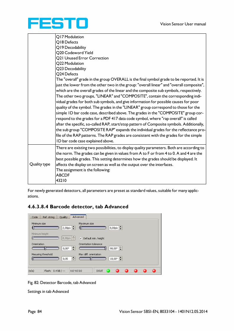
Page 84 Vision Sensor SBSI-EN, 8033104 - 1401N12.05.2014
Vision Sensor User manual
Q17 Modulation
Q18 Defects
Q19 Decodability
Q20 Codeword Yield
Q21 Unused Error Correction
Q22 Modulation
Q23 Decodability
Q24 Defects
The "overall" grade in the group OVERALL is the final symbol grade to be reported. It is
just the lower from the other two in the group: "overall linear" and "overall composite",
which are the overall grades of the linear and the composite sub symbols, respectively.
The other two groups, "LINEAR" and "COMPOSITE", contain the corresponding indi-
vidual grades for both sub symbols, and give information for possible causes for poor
quality of the symbol. The grades in the "LINEAR" group correspond to those for the
simple 1D bar code case, described above. The grades in the "COMPOSITE" group cor-
respond to the grades for a PDF 417 data code symbol, where "rap overall" is called
after the specific, so-called RAP, start/stop pattern of Composite symbols. Additionally,
the sub group "COMPOSITE RAP" expands the individual grades for the reflectance pro-
file of the RAP patterns. The RAP grades are consistent with the grades for the simple
1D bar code case explained above.
Quality type
There are existing two possibilities, to display quality parameters. Both are according to
the norm. The grades can be given in values from A to F or from 4 to 0. A and 4 are the
best possible grades. This setting determines how the grades should be displayed. It
affects the display on screen as well as the output over the interfaces.
The assignment is the following:
ABCDF
43210
For newly generated detectors, all parameters are preset as standard values, suitable for many applic-
ations.
4.6.3.8.4 Barcode detector, tab Advanced
Fig. 82: Detector Barcode, tab Advanced
Settings in tab Advanced
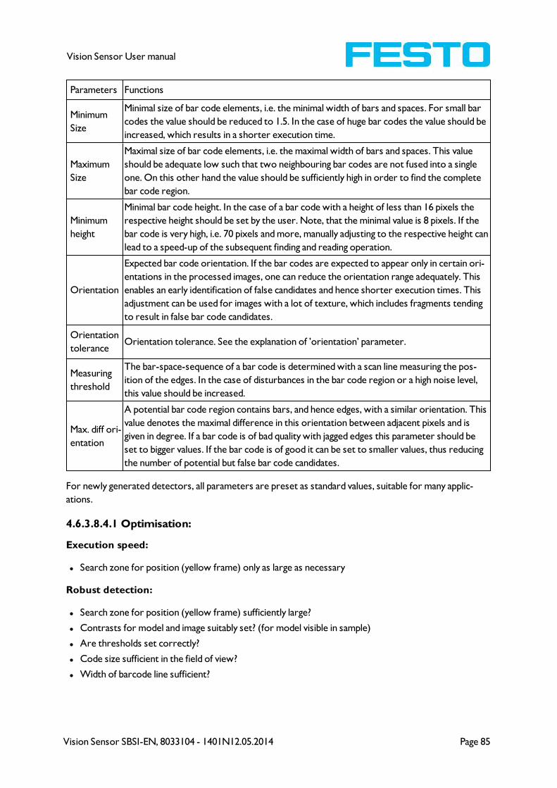
Vision Sensor SBSI-EN, 8033104 - 1401N12.05.2014 Page 85
Vision Sensor User manual
Parameters Functions
Minimum
Size
Minimal size of bar code elements, i.e. the minimal width of bars and spaces. For small bar
codes the value should be reduced to 1.5. In the case of huge bar codes the value should be
increased, which results in a shorter execution time.
Maximum
Size
Maximal size of bar code elements, i.e. the maximal width of bars and spaces. This value
should be adequate low such that two neighbouring bar codes are not fused into a single
one. On this other hand the value should be sufficiently high in order to find the complete
bar code region.
Minimum
height
Minimal bar code height. In the case of a bar code with a height of less than 16 pixels the
respective height should be set by the user. Note, that the minimal value is 8 pixels. If the
bar code is very high, i.e. 70 pixels and more, manually adjusting to the respective height can
lead to a speed-up of the subsequent finding and reading operation.
Orientation
Expected bar code orientation. If the bar codes are expected to appear only in certain ori-
entations in the processed images, one can reduce the orientation range adequately. This
enables an early identification of false candidates and hence shorter execution times. This
adjustment can be used for images with a lot of texture, which includes fragments tending
to result in false bar code candidates.
Orientation
toleranceOrientation tolerance. See the explanation of ’orientation’ parameter.
Measuring
threshold
The bar-space-sequence of a bar code is determined with a scan line measuring the pos-
ition of the edges. In the case of disturbances in the bar code region or a high noise level,
this value should be increased.
Max. diff ori-
entation
A potential bar code region contains bars, and hence edges, with a similar orientation. This
value denotes the maximal difference in this orientation between adjacent pixels and is
given in degree. If a bar code is of bad quality with jagged edges this parameter should be
set to bigger values. If the bar code is of good it can be set to smaller values, thus reducing
the number of potential but false bar code candidates.
For newly generated detectors, all parameters are preset as standard values, suitable for many applic-
ations.
4.6.3.8.4.1 Optimisation:
Execution speed:
l Search zone for position (yellow frame) only as large as necessary
Robust detection:
l Search zone for position (yellow frame) sufficiently large?
l Contrasts for model and image suitably set? (for model visible in sample)
l Are thresholds set correctly?
l Code size sufficient in the field of view?
l Width of barcode line sufficient?

Page 86 Vision Sensor SBSI-EN, 8033104 - 1401N12.05.2014
Vision Sensor User manual
4.6.3.9 2D Code detector
4.6.3.9.1 2D Code detector, tab Code
Next topic:
2D Code detector, tab Ref. String (Page 87)
Fig. 83: Detector 2D Code, tab Code
Settings in tab Code
Parameters Functions
Symbol
typeSelect here the type of code to be read with the Code reader.
Code
length
Max. Length of a barcode. If the contents of code are longer, the rest will be cut off. If
more than one code is read by this detector, this value has to be set for the longest code.
Min. num-
ber of
codes
Minimum number of codes to be read inside the search area.
Max. num-
ber of
codes
Maximum number of codes to be read inside the search area. If this value is set higher than
necessary, the reading time may increase slightly.
Reset
Reset parameters are for setting the code reading parameters back to the default state
before teaching. There can be selected "standard", "enhanced" and "maximum". "Standard"
is setting the default parameters in a way that most of the codes can be read. If your code
can not be read, please use setting "Enhanced". If the code still cannot be read, use setting
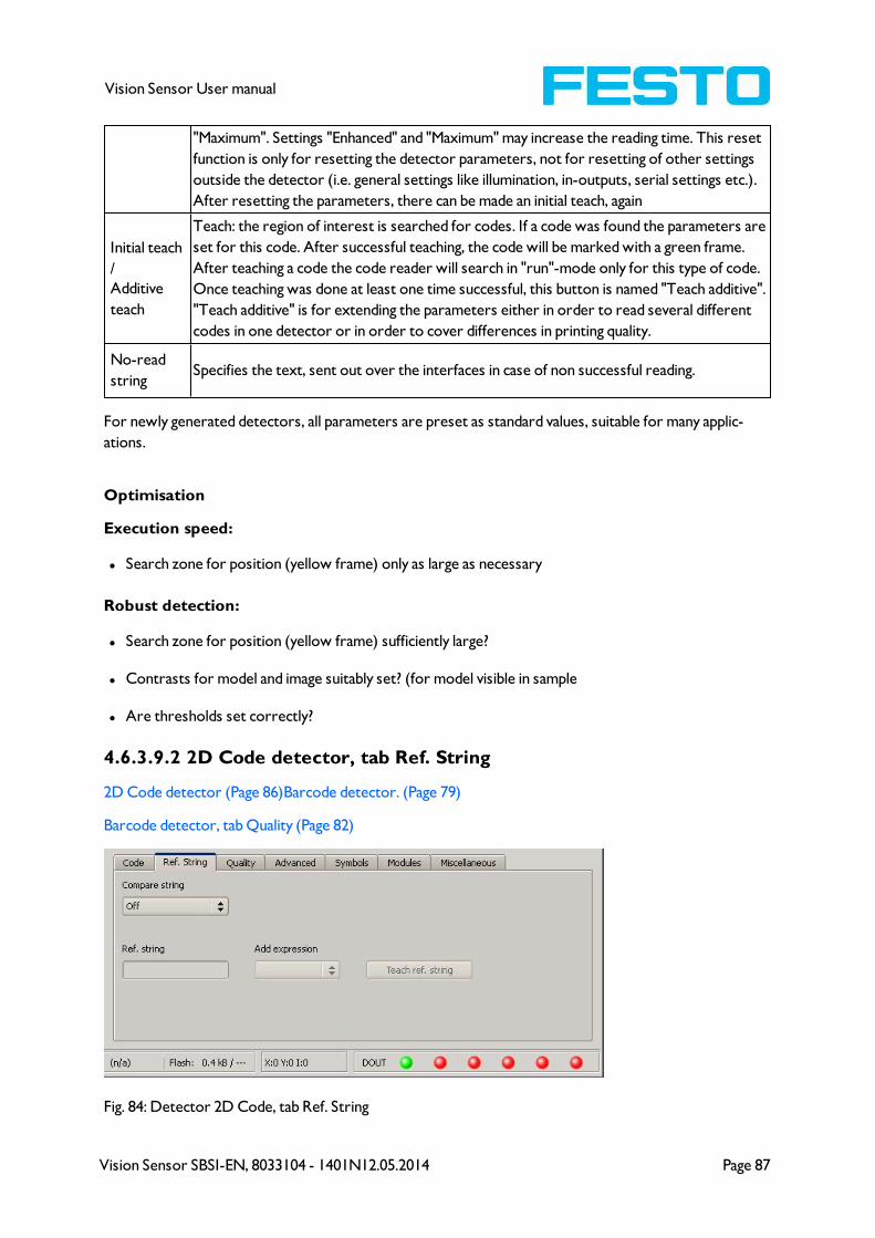
Vision Sensor SBSI-EN, 8033104 - 1401N12.05.2014 Page 87
Vision Sensor User manual
"Maximum". Settings "Enhanced" and "Maximum" may increase the reading time. This reset
function is only for resetting the detector parameters, not for resetting of other settings
outside the detector (i.e. general settings like illumination, in-outputs, serial settings etc.).
After resetting the parameters, there can be made an initial teach, again
Initial teach
/
Additive
teach
Teach: the region of interest is searched for codes. If a code was found the parameters are
set for this code. After successful teaching, the code will be marked with a green frame.
After teaching a code the code reader will search in "run"-mode only for this type of code.
Once teaching was done at least one time successful, this button is named "Teach additive".
"Teach additive" is for extending the parameters either in order to read several different
codes in one detector or in order to cover differences in printing quality.
No-read
stringSpecifies the text, sent out over the interfaces in case of non successful reading.
For newly generated detectors, all parameters are preset as standard values, suitable for many applic-
ations.
Optimisation
Execution speed:
l Search zone for position (yellow frame) only as large as necessary
Robust detection:
l Search zone for position (yellow frame) sufficiently large?
l Contrasts for model and image suitably set? (for model visible in sample
l Are thresholds set correctly?
4.6.3.9.2 2D Code detector, tab Ref. String
2D Code detector (Page 86)Barcode detector. (Page 79)
Barcode detector, tab Quality (Page 82)
Fig. 84: Detector 2D Code, tab Ref. String
Page 88 Vision Sensor SBSI-EN, 8033104 - 1401N12.05.2014
Vision Sensor User manual
Settings in tab Reference String
Parameters Functions
Compare
string
Activates verification of contents of the result information. The verification is done by
using of regular expressions.
Ref. stringThis text or regular expression is taken for verification. Here can be entered characters
or regular expressions.
Add expres-
sionOpens a list with examples for regular expressions
Teach ref.
string
Reads the code under the code reader and takes the contents of this code as a ref-
erence string. This text can be changed later.
For newly generated detectors, all parameters are preset as standard values, suitable for many applic-
ations.
Reference string Hit Example for hit
123 String containing 123 01234
\A123 String beginning with 123 1234
123\Z String ending by 123 0123
\A123\Z String matching exactly 123 123
[123] String containing one of the characters 33
[123]{2} String containing sequence of the characters of length 2 23
[12]|[34] String containing a character of one of both groups 4
Most important elements of regular expressions:
^ or \AMatches start of string
$ or \ZMatches end of string (a trailing newline is allowed)
.Matches any character except newline
[...]Matches any character listed in the brackets. If the first character is a '^', this matches any character
except those in the list. You can use the '-' character as in '[A-Z0-9]' to select character ranges. Other
characters lose their special meaning in brackets, except '\'.
*Allows 0 or more repetitions of preceding literal or group
+Allows 1 or more repetitions
?Allows 0 or 1 repetitions
{n,m}Allows n to m repetitions
{n}Allows exactly n repetitions
|Separates alternative search expressions)

Vision Sensor SBSI-EN, 8033104 - 1401N12.05.2014 Page 89
Vision Sensor User manual
4.6.3.9.3 2D Code detector, tab Quality
2D Code detector, tab Ref. String (Page 87)
2D Code detector, tab Advanced (Page 90)
Fig. 85: Detector 2D Code, tab Quality
Settings in tab Quality
Parameters Functions
Quality
param.
Quality parameters are additional information for rating the printing quality of the code.
There are two different standards: AIM DPM-1-2006 and ISO/IEC 15415. Quality para-
meters are eight single parameters, the definition of the respective elements is as fol-
lows:
Q1 Overall quality
Q2 Contrast
Q3 Modulation
Q4 Fixed pattern damage
Q5 Decode
Q6 Axial non-uniformity
Q7 Grid non-uniformity
Q8 Unused error correction
Q9 Mean light
The overall quality is the minimum of all individual grades.
The contrast is the range between the minimal and the maximal pixel intensity in the data
code domain, and a strong contrast results in a good grading.
The modulation indicates how strong the amplitudes of the data code modules are. Big
amplitudes make the assignment of the modules to black or white more certain, res-
ulting in a high modulation grade.
The fixed pattern of both ECC200 and QR Code is of high importance for detecting and
decoding the codes. Degradation or damage of the fixed pattern, or the respective quiet
zones, is assessed with the fixed pattern damage quality.
The decode quality always takes the grade 4, meaning that the code could be decoded.
Naturally, codes which cannot be decoded cannot be assessed concerning print quality
either.
Originally, data codes have squared modules, i.e. the width and height of the modules are
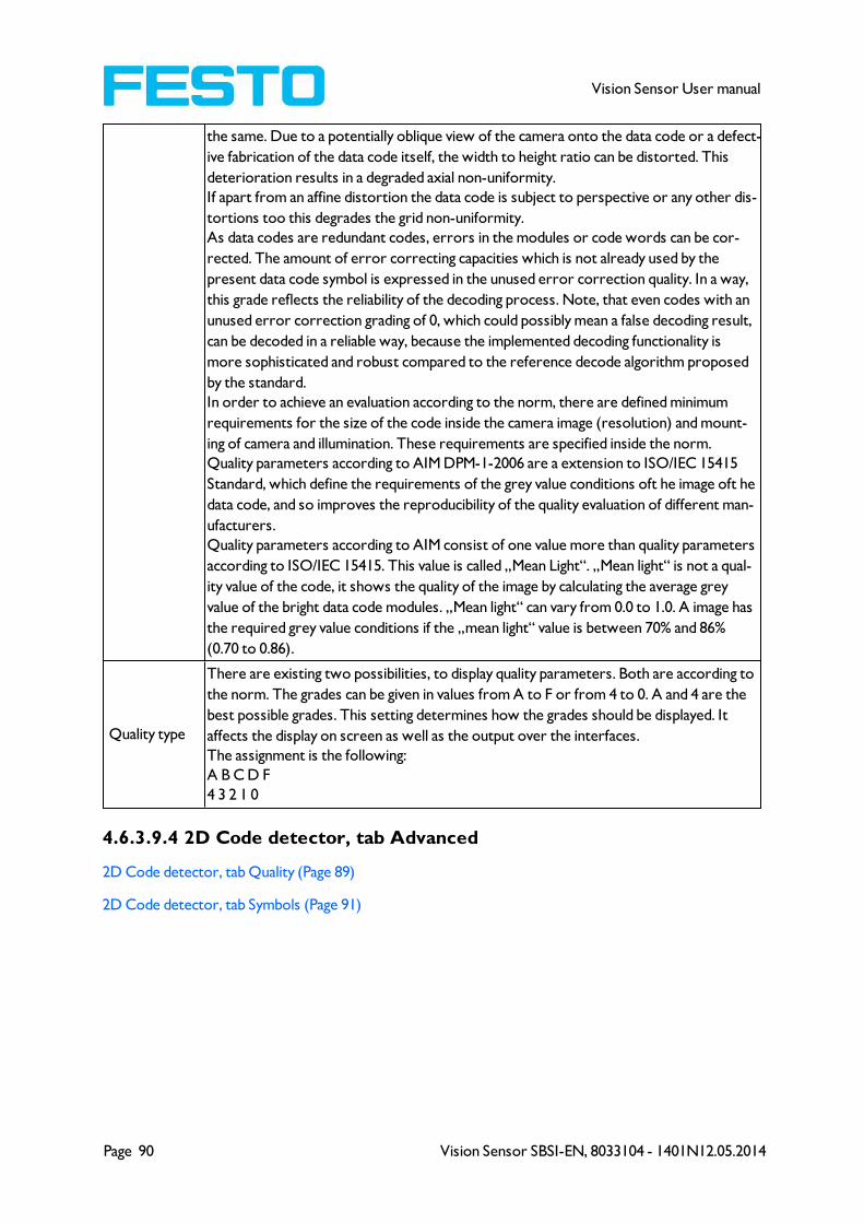
Page 90 Vision Sensor SBSI-EN, 8033104 - 1401N12.05.2014
Vision Sensor User manual
the same. Due to a potentially oblique view of the camera onto the data code or a defect-
ive fabrication of the data code itself, the width to height ratio can be distorted. This
deterioration results in a degraded axial non-uniformity.
If apart from an affine distortion the data code is subject to perspective or any other dis-
tortions too this degrades the grid non-uniformity.
As data codes are redundant codes, errors in the modules or code words can be cor-
rected. The amount of error correcting capacities which is not already used by the
present data code symbol is expressed in the unused error correction quality. In a way,
this grade reflects the reliability of the decoding process. Note, that even codes with an
unused error correction grading of 0, which could possibly mean a false decoding result,
can be decoded in a reliable way, because the implemented decoding functionality is
more sophisticated and robust compared to the reference decode algorithm proposed
by the standard.
In order to achieve an evaluation according to the norm, there are defined minimum
requirements for the size of the code inside the camera image (resolution) and mount-
ing of camera and illumination. These requirements are specified inside the norm.
Quality parameters according to AIM DPM-1-2006 are a extension to ISO/IEC 15415
Standard, which define the requirements of the grey value conditions oft he image oft he
data code, and so improves the reproducibility of the quality evaluation of different man-
ufacturers.
Quality parameters according to AIM consist of one value more than quality parameters
according to ISO/IEC 15415. This value is called „Mean Light“. „Mean light“ is not a qual-
ity value of the code, it shows the quality of the image by calculating the average grey
value of the bright data code modules. „Mean light“ can vary from 0.0 to 1.0. A image has
the required grey value conditions if the „mean light“ value is between 70% and 86%
(0.70 to 0.86).
Quality type
There are existing two possibilities, to display quality parameters. Both are according to
the norm. The grades can be given in values from A to F or from 4 to 0. A and 4 are the
best possible grades. This setting determines how the grades should be displayed. It
affects the display on screen as well as the output over the interfaces.
The assignment is the following:
A B C D F
4 3 2 1 0
4.6.3.9.4 2D Code detector, tab Advanced
2D Code detector, tab Quality (Page 89)
2D Code detector, tab Symbols (Page 91)
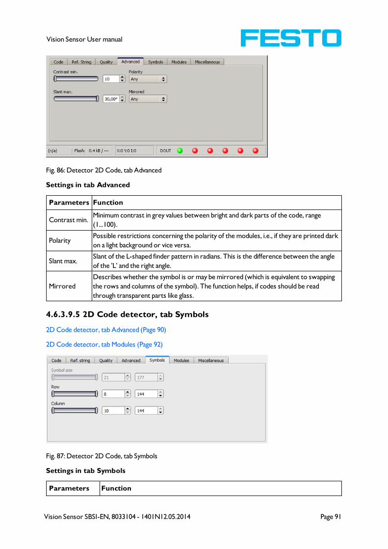
Vision Sensor SBSI-EN, 8033104 - 1401N12.05.2014 Page 91
Vision Sensor User manual
Fig. 86: Detector 2D Code, tab Advanced
Settings in tab Advanced
Parameters Function
Contrast min.Minimum contrast in grey values between bright and dark parts of the code, range
(1...100).
PolarityPossible restrictions concerning the polarity of the modules, i.e., if they are printed dark
on a light background or vice versa.
Slant max.Slant of the L-shaped finder pattern in radians. This is the difference between the angle
of the ’L’ and the right angle.
Mirrored
Describes whether the symbol is or may be mirrored (which is equivalent to swapping
the rows and columns of the symbol). The function helps, if codes should be read
through transparent parts like glass.
4.6.3.9.5 2D Code detector, tab Symbols
2D Code detector, tab Advanced (Page 90)
2D Code detector, tab Modules (Page 92)
Fig. 87: Detector 2D Code, tab Symbols
Settings in tab Symbols
Parameters Function
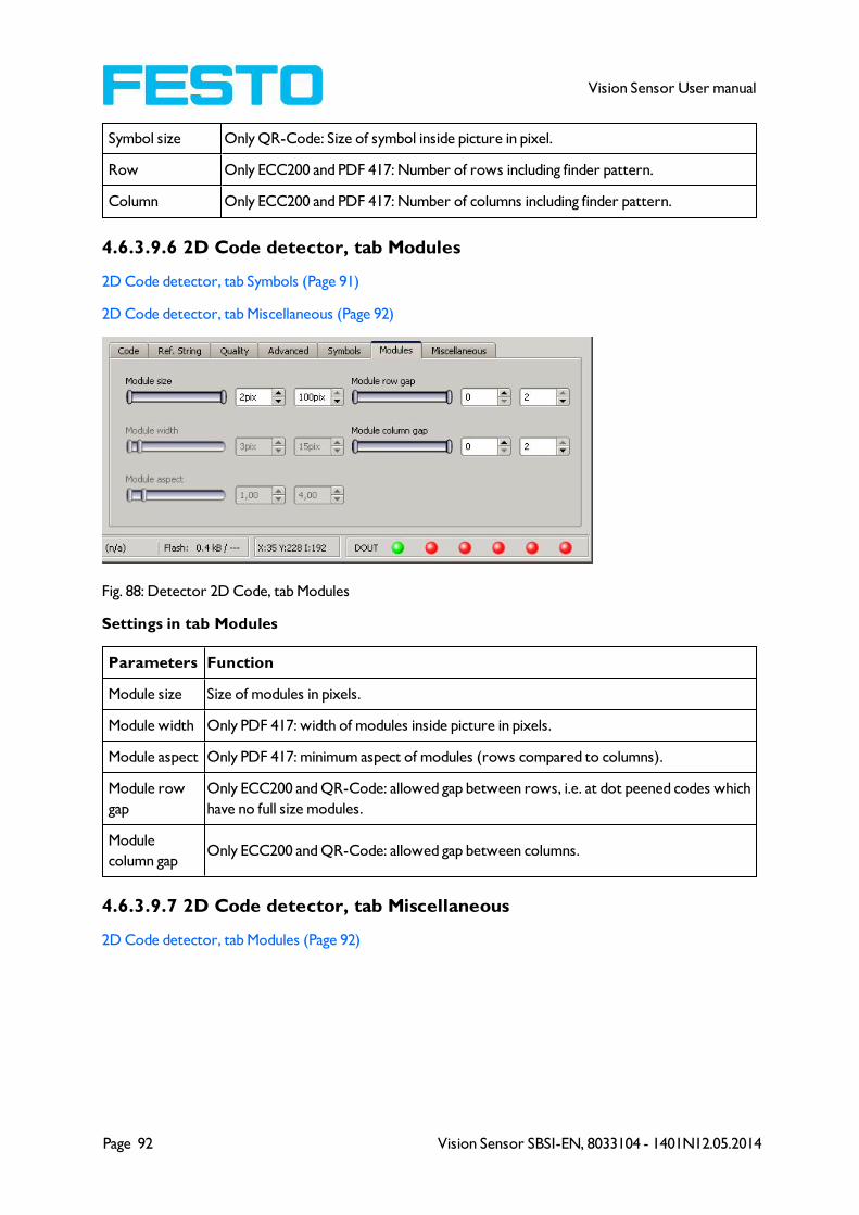
Page 92 Vision Sensor SBSI-EN, 8033104 - 1401N12.05.2014
Vision Sensor User manual
Symbol size Only QR-Code: Size of symbol inside picture in pixel.
Row Only ECC200 and PDF 417: Number of rows including finder pattern.
Column Only ECC200 and PDF 417: Number of columns including finder pattern.
4.6.3.9.6 2D Code detector, tab Modules
2D Code detector, tab Symbols (Page 91)
2D Code detector, tab Miscellaneous (Page 92)
Fig. 88: Detector 2D Code, tab Modules
Settings in tab Modules
Parameters Function
Module size Size of modules in pixels.
Module width Only PDF 417: width of modules inside picture in pixels.
Module aspect Only PDF 417: minimum aspect of modules (rows compared to columns).
Module row
gap
Only ECC200 and QR-Code: allowed gap between rows, i.e. at dot peened codes which
have no full size modules.
Module
column gapOnly ECC200 and QR-Code: allowed gap between columns.
4.6.3.9.7 2D Code detector, tab Miscellaneous
2D Code detector, tab Modules (Page 92)
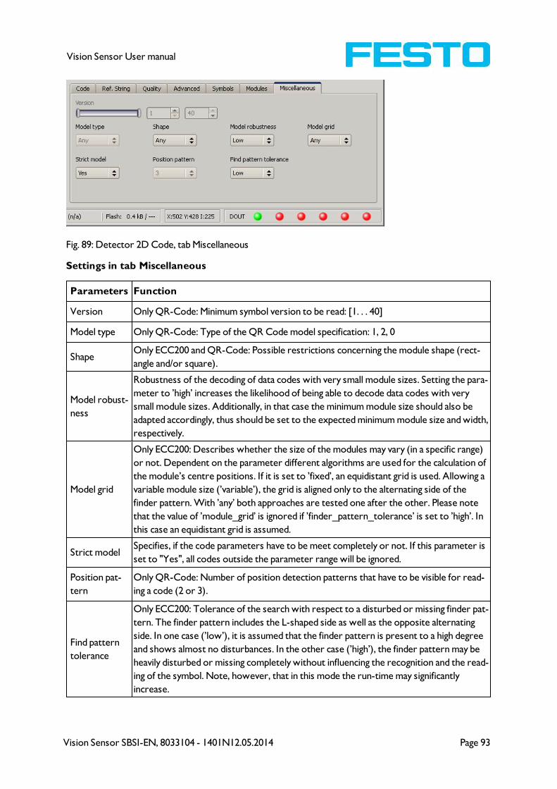
Vision Sensor SBSI-EN, 8033104 - 1401N12.05.2014 Page 93
Vision Sensor User manual
Fig. 89: Detector 2D Code, tab Miscellaneous
Settings in tab Miscellaneous
Parameters Function
Version Only QR-Code: Minimum symbol version to be read: [1. . . 40]
Model type Only QR-Code: Type of the QR Code model specification: 1, 2, 0
ShapeOnly ECC200 and QR-Code: Possible restrictions concerning the module shape (rect-
angle and/or square).
Model robust-
ness
Robustness of the decoding of data codes with very small module sizes. Setting the para-
meter to ’high’ increases the likelihood of being able to decode data codes with very
small module sizes. Additionally, in that case the minimum module size should also be
adapted accordingly, thus should be set to the expected minimum module size and width,
respectively.
Model grid
Only ECC200: Describes whether the size of the modules may vary (in a specific range)
or not. Dependent on the parameter different algorithms are used for the calculation of
the module’s centre positions. If it is set to ’fixed’, an equidistant grid is used. Allowing a
variable module size (’variable’), the grid is aligned only to the alternating side of the
finder pattern. With ’any’ both approaches are tested one after the other. Please note
that the value of ’module_grid’ is ignored if ’finder_pattern_tolerance’ is set to ’high’. In
this case an equidistant grid is assumed.
Strict modelSpecifies, if the code parameters have to be meet completely or not. If this parameter is
set to "Yes", all codes outside the parameter range will be ignored.
Position pat-
tern
Only QR-Code: Number of position detection patterns that have to be visible for read-
ing a code (2 or 3).
Find pattern
tolerance
Only ECC200: Tolerance of the search with respect to a disturbed or missing finder pat-
tern. The finder pattern includes the L-shaped side as well as the opposite alternating
side. In one case (’low’), it is assumed that the finder pattern is present to a high degree
and shows almost no disturbances. In the other case (’high’), the finder pattern may be
heavily disturbed or missing completely without influencing the recognition and the read-
ing of the symbol. Note, however, that in this mode the run-time may significantly
increase.

Page 94 Vision Sensor SBSI-EN, 8033104 - 1401N12.05.2014
Vision Sensor User manual
4.6.4 Output of inspection results
Here you define the assignment and logical connection of the digital signal outputs as well as the interfaces
and output data of your Vision Sensor.
I/O mapping (Page 94)
Output signals (Digital outputs / Logic) (Page 99)
Interfaces (Page 100)
Timing, Digital outputs (Page 101)
Telegram, Data output (Page 107)
4.6.4.1 I/O mappingHere the following settings can be made:
1. Definition, if I/O is used as an input or output (Pin 05 - 08, can be used as input or output)
2. Assignment of functionality to inputs and outputs. In the list-box there can be seen and selected all
available functions for this input or output. Some functions can be assigned only to one special input
or output (e.g. HW/Trigger).
Fig. 90: Output, I/O Mapping
4.6.4.1.1 Functions of inputs
Function Description
H/W Trigger Hardware Trigger (only on pin 03 WH available)
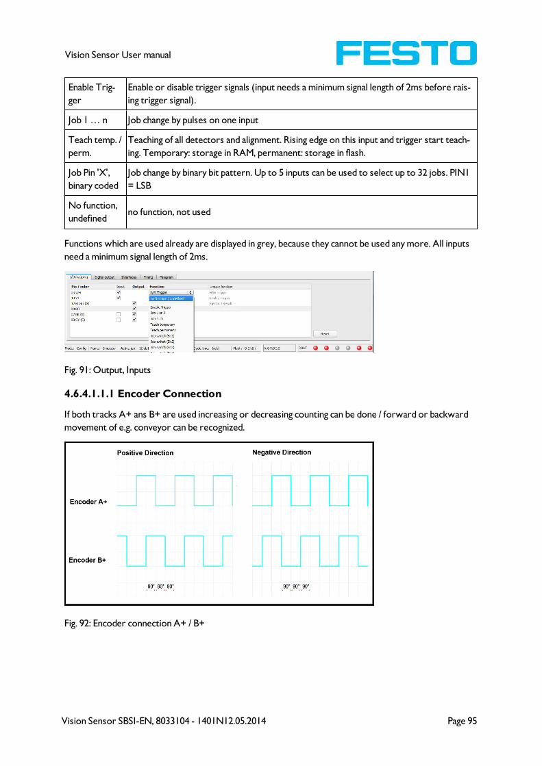
Vision Sensor SBSI-EN, 8033104 - 1401N12.05.2014 Page 95
Vision Sensor User manual
Enable Trig-
ger
Enable or disable trigger signals (input needs a minimum signal length of 2ms before rais-
ing trigger signal).
Job 1 … n Job change by pulses on one input
Teach temp. /
perm.
Teaching of all detectors and alignment. Rising edge on this input and trigger start teach-
ing. Temporary: storage in RAM, permanent: storage in flash.
Job Pin 'X',
binary coded
Job change by binary bit pattern. Up to 5 inputs can be used to select up to 32 jobs. PIN1
= LSB
No function,
undefinedno function, not used
Functions which are used already are displayed in grey, because they cannot be used any more. All inputs
need a minimum signal length of 2ms.
Fig. 91: Output, Inputs
4.6.4.1.1.1 Encoder Connection
If both tracks A+ ans B+ are used increasing or decreasing counting can be done / forward or backward
movement of e.g. conveyor can be recognized.
Fig. 92: Encoder connection A+ / B+
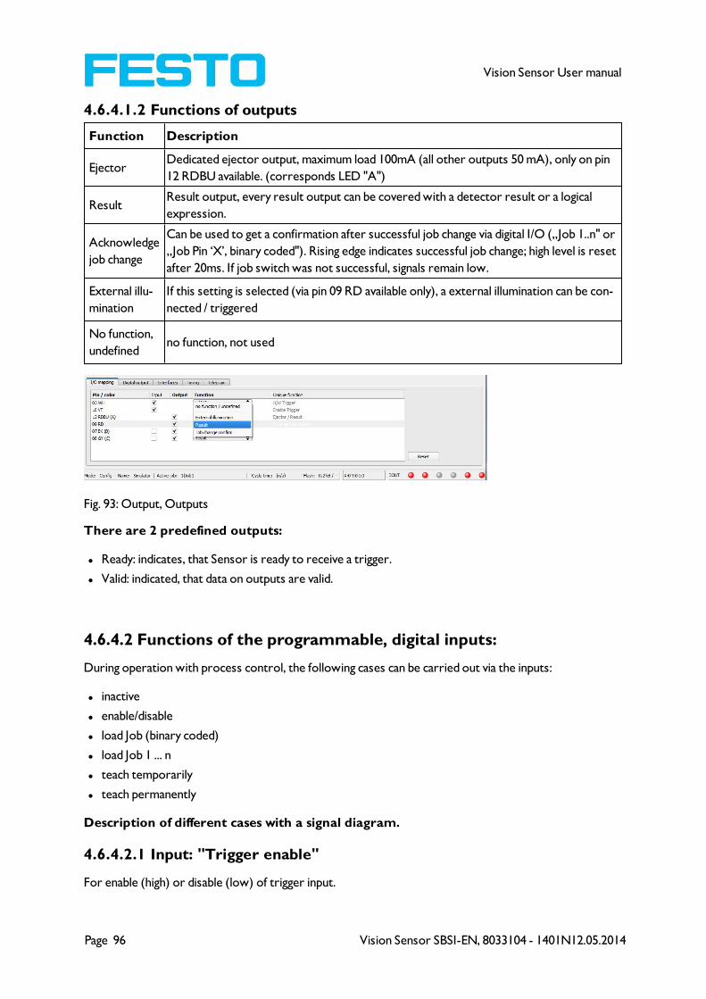
Page 96 Vision Sensor SBSI-EN, 8033104 - 1401N12.05.2014
Vision Sensor User manual
4.6.4.1.2 Functions of outputs
Function Description
EjectorDedicated ejector output, maximum load 100mA (all other outputs 50 mA), only on pin
12 RDBU available. (corresponds LED "A")
ResultResult output, every result output can be covered with a detector result or a logical
expression.
Acknowledge
job change
Can be used to get a confirmation after successful job change via digital I/O („Job 1..n" or
„Job Pin ‘X’, binary coded"). Rising edge indicates successful job change; high level is reset
after 20ms. If job switch was not successful, signals remain low.
External illu-
mination
If this setting is selected (via pin 09 RD available only), a external illumination can be con-
nected / triggered
No function,
undefinedno function, not used
Fig. 93: Output, Outputs
There are 2 predefined outputs:
l Ready: indicates, that Sensor is ready to receive a trigger.
l Valid: indicated, that data on outputs are valid.
4.6.4.2 Functions of the programmable, digital inputs:
During operation with process control, the following cases can be carried out via the inputs:
l inactive
l enable/disable
l load Job (binary coded)
l load Job 1 ... n
l teach temporarily
l teach permanently
Description of different cases with a signal diagram.
4.6.4.2.1 Input: "Trigger enable"
For enable (high) or disable (low) of trigger input.

Vision Sensor SBSI-EN, 8033104 - 1401N12.05.2014 Page 97
Vision Sensor User manual
Fig. 94: Input timing, Trigger enable
4.6.4.2.2 Input: Job change binary or by function Job 1 or 2:
Job change binary over up to 5 inputs (Job 1- max. 31):
Possible only if Ready = high. As soon as the binary input signal change Ready is set to low.
Ready remains low until switch-over to the new job is done. If the option “Job change confirm” is used,
this signal occurs after the job change, and hereafter "Ready" is set high again. During Job Change via binary
inputs there must not be sent any trigger signal. The change of the logic levels of the according inputs must
happen at the same time (during maximum 10ms all inputs must have a stable logic level)
Job change by function: Job 1 or 2:
Possible only if Ready = high. At the level change of the according input Ready is set low. Ready remains
low till the job change is done. If the option “Job change confirm” is used, this signal occurs after the job
change, and hereafter "Ready" is set high again. During Job Change over binary inputs there must not be
sent any trigger signal. A high level causes evaluation according to job 2; a low level produces evaluation
according to job 1.
Differences between binary switching and Job 1 or 2:
By usage of binary job switch the desired job number must be represented binary coded via the selected
inputs. Therefore in this mode to switch between 2 jobs minimum 2 inputs are necessary.
In case of Job change Job 1 or 2 a high level cause’s evaluation according to job 2, a low level produces eval-
uation according to job 1. In this way with only one input two the switching between two jobs can be
done.
Fig. 95: Input timing, Job change via Binary / Job 1 or 2
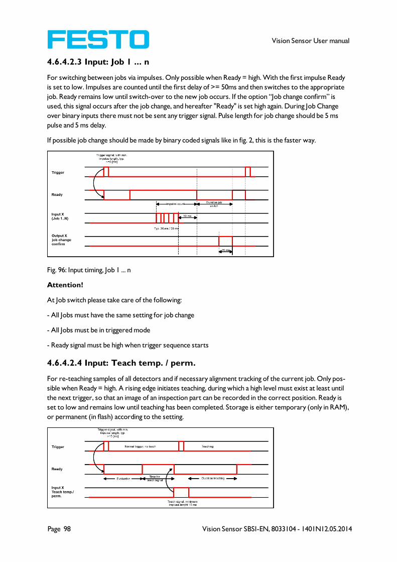
Page 98 Vision Sensor SBSI-EN, 8033104 - 1401N12.05.2014
Vision Sensor User manual
4.6.4.2.3 Input: Job 1 ... n
For switching between jobs via impulses. Only possible when Ready = high. With the first impulse Ready
is set to low. Impulses are counted until the first delay of >= 50ms and then switches to the appropriate
job. Ready remains low until switch-over to the new job occurs. If the option “Job change confirm” is
used, this signal occurs after the job change, and hereafter "Ready" is set high again. During Job Change
over binary inputs there must not be sent any trigger signal. Pulse length for job change should be 5 ms
pulse and 5 ms delay.
If possible job change should be made by binary coded signals like in fig. 2, this is the faster way.
Fig. 96: Input timing, Job 1 ... n
Attention!
At Job switch please take care of the following:
- All Jobs must have the same setting for job change
- All Jobs must be in triggered mode
- Ready signal must be high when trigger sequence starts
4.6.4.2.4 Input: Teach temp. / perm.
For re-teaching samples of all detectors and if necessary alignment tracking of the current job. Only pos-
sible when Ready = high. A rising edge initiates teaching, during which a high level must exist at least until
the next trigger, so that an image of an inspection part can be recorded in the correct position. Ready is
set to low and remains low until teaching has been completed. Storage is either temporary (only in RAM),
or permanent (in flash) according to the setting.

Vision Sensor SBSI-EN, 8033104 - 1401N12.05.2014 Page 99
Vision Sensor User manual
Fig. 97: Input timing, Teach
Attention!
The functions Job 1 or 2, Job 1 ... n or teach temp. /perm. can only be used in trigger mode
4.6.4.3 Output signals (Digital outputs / Logic)
In this tab, you define the switching behaviour and logical connection of the digital outputs. Number of out-
puts depends from settings in tab IO mapping.
Fig. 98: Output, tab digital output
Description of different cases with a signal diagram.
For each pin (output) there are the following possibilities:
Parameter Function
Overall job
resultNo physical output, effects recorder, statistics and archiving functions
Invert Invert total result for this pin (output)
Mode
Standard: combine several detectors by logical expressions like AND (&) / OR (|) / NOT
(!) to one logical expression.
Advanced: Free edit of logical expression.
NOT Select: operator NOT (!)
Logic Select: operator AND (&) / OR (|)
D1 - D...All active detectors are shown in this list depending from number of detectors. These
can be assigned to the listed output. Each detector can be set to on, off and invert.
Logical
Expression
Here is shown either the logical expression that was build automatically by using of stand-
ard mode or the logical expression can be entered free by using the advanced mode.
Defining logical connection:
Define the logical connection between the inspection results of the individual detectors and the status of
the selected output. You have two input possibilities:
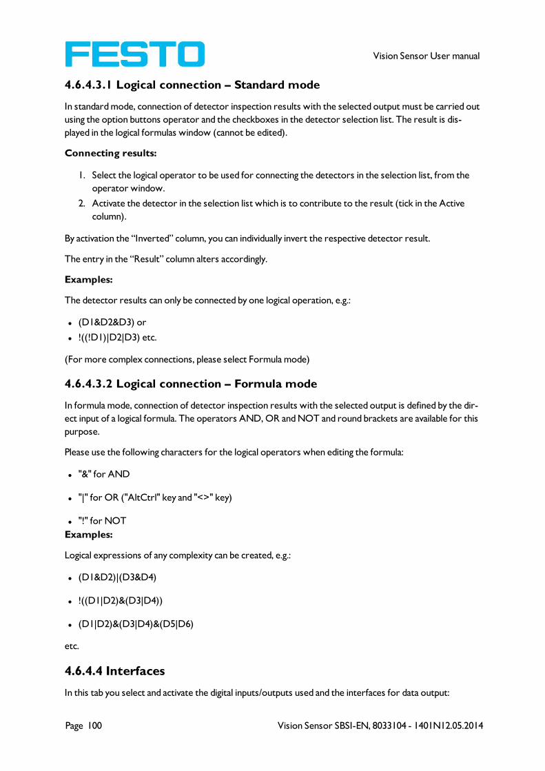
Page 100 Vision Sensor SBSI-EN, 8033104 - 1401N12.05.2014
Vision Sensor User manual
4.6.4.3.1 Logical connection – Standard mode
In standard mode, connection of detector inspection results with the selected output must be carried out
using the option buttons operator and the checkboxes in the detector selection list. The result is dis-
played in the logical formulas window (cannot be edited).
Connecting results:
1. Select the logical operator to be used for connecting the detectors in the selection list, from the
operator window.
2. Activate the detector in the selection list which is to contribute to the result (tick in the Active
column).
By activation the “Inverted” column, you can individually invert the respective detector result.
The entry in the “Result” column alters accordingly.
Examples:
The detector results can only be connected by one logical operation, e.g.:
l (D1&D2&D3) or
l !((!D1)|D2|D3) etc.
(For more complex connections, please select Formula mode)
4.6.4.3.2 Logical connection – Formula mode
In formula mode, connection of detector inspection results with the selected output is defined by the dir-
ect input of a logical formula. The operators AND, OR and NOT and round brackets are available for this
purpose.
Please use the following characters for the logical operators when editing the formula:
l "&" for AND
l "|" for OR ("AltCtrl" key and "<>" key)
l "!" for NOT
Examples:
Logical expressions of any complexity can be created, e.g.:
l (D1&D2)|(D3&D4)
l !((D1|D2)&(D3|D4))
l (D1|D2)&(D3|D4)&(D5|D6)
etc.
4.6.4.4 Interfaces
In this tab you select and activate the digital inputs/outputs used and the interfaces for data output:
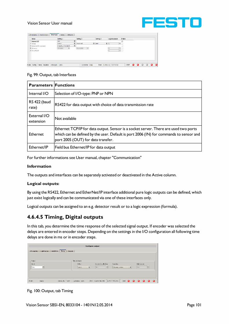
Vision Sensor SBSI-EN, 8033104 - 1401N12.05.2014 Page 101
Vision Sensor User manual
Fig. 99: Output, tab Interfaces
Parameters Functions
Internal I/O Selection of I/O-type: PNP or NPN
RS 422 (baud
rate)RS422 for data output with choice of data transmission rate
External I/O
extensionNot available
Ethernet
Ethernet TCP/IP for data output. Sensor is a socket server. There are used two ports
which can be defined by the user. Default is port 2006 (IN) for commands to sensor and
port 2005 (OUT) for data transfer.
Ethernet/IP Field bus Ethernet/IP for data output
For further informations see User manual, chapter "Communication"
Information
The outputs and interfaces can be separately activated or deactivated in the Active column.
Logical outputs:
By using the RS422, Ethernet and EtherNet/IP interface additional pure logic outputs can be defined, which
just exist logically and can be communicated via one of these interfaces only.
Logical outputs can be assigned to an e.g. detector result or to a logic expression (formula).
4.6.4.5 Timing, Digital outputs
In this tab, you determine the time response of the selected signal output. If encoder was selected the
delays are entered in encoder steps. Depending on the settings in the I/O configuration all following time
delays are done in ms or in encoder steps.
Fig. 100: Output, tab Timing

Page 102 Vision Sensor SBSI-EN, 8033104 - 1401N12.05.2014
Vision Sensor User manual
Parameters Functions
Trigger delay Time between trigger and start of image recording in ms
Digital outputs All outputs can be delayed or only the ejector output.
EjectorTime between trigger and connection of result level at the signal outputs. Includes eval-
uation time.
Reset signal Determines, how to reset outputs.
Duration of res-
ultDuration of result signal in ms
Attention:
At Job Change and change from Run- to Config Mode outputs will get the following states: Buffer of
delayed outputs will be deleted.
Digital outputs:
Will be reset to default at change from "Run" to "Config". Defaults are set by flag "Invert" in output tab.
"Invert" inverts the default setting and also the result.
Reset of digital outputs:
The reset of the result outputs can happen depending on different settings 7 events. This are:
l “Change on result” (default).
The output changes its level according to the logical result when the next logical result is generated
and valid. Typical use at controlling switch points e.g. in sorting applications.
l “Change on trigger”
The output is set to “inactive” (in operating mode PNP = low) with the next trigger. Typical use at
operation with a PLC.
l “Valid duration”
The output changes back to inactive after the "Valid" duration time setting here in ms. typical use with
e.g. pneumatic ejectors.
S. Vision Sensor Configuration Studio/Output/Timing/Signalling
READY AND VALID
l If Ready = high: Ready for next image / evaluation.
l If Valid = high: Results are valid at the outputs.
PNP or NPN operating mode.
All the described examples are in the operation mode „PNP“. If the setting „NPN“ is used, the examples
are valid, but with inverted signal levels.
S. Vision Sensor Configuration Studio/Output/Interfaces/Internal I/O
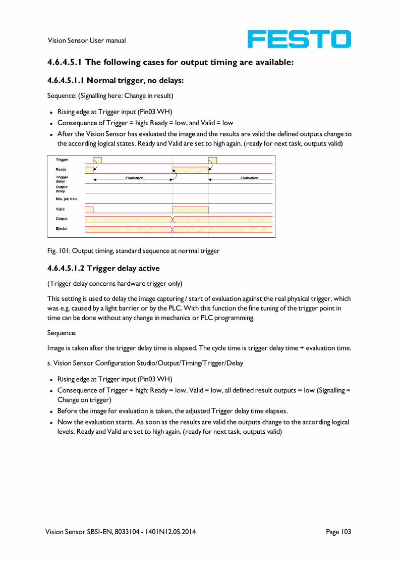
Vision Sensor SBSI-EN, 8033104 - 1401N12.05.2014 Page 103
Vision Sensor User manual
4.6.4.5.1 The following cases for output timing are available:
4.6.4.5.1.1 Normal trigger, no delays:
Sequence: (Signalling here: Change in result)
l Rising edge at Trigger input (Pin03 WH)
l Consequence of Trigger = high: Ready = low, and Valid = low
l After the Vision Sensor has evaluated the image and the results are valid the defined outputs change to
the according logical states. Ready and Valid are set to high again. (ready for next task, outputs valid)
Fig. 101: Output timing, standard sequence at normal trigger
4.6.4.5.1.2 Trigger delay active
(Trigger delay concerns hardware trigger only)
This setting is used to delay the image capturing / start of evaluation against the real physical trigger, which
was e.g. caused by a light barrier or by the PLC. With this function the fine tuning of the trigger point in
time can be done without any change in mechanics or PLC programming.
Sequence:
Image is taken after the trigger delay time is elapsed. The cycle time is trigger delay time + evaluation time.
s. Vision Sensor Configuration Studio/Output/Timing/Trigger/Delay
l Rising edge at Trigger input (Pin03 WH)
l Consequence of Trigger = high: Ready = low, Valid = low, all defined result outputs = low (Signalling =
Change on trigger)
l Before the image for evaluation is taken, the adjusted Trigger delay time elapses.
l Now the evaluation starts. As soon as the results are valid the outputs change to the according logical
levels. Ready and Valid are set to high again. (ready for next task, outputs valid)
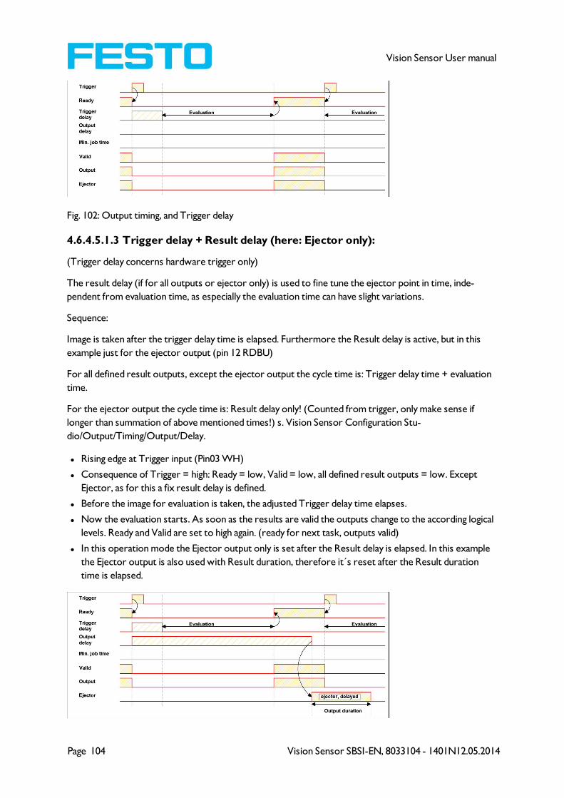
Page 104 Vision Sensor SBSI-EN, 8033104 - 1401N12.05.2014
Vision Sensor User manual
Fig. 102: Output timing, and Trigger delay
4.6.4.5.1.3 Trigger delay + Result delay (here: Ejector only):
(Trigger delay concerns hardware trigger only)
The result delay (if for all outputs or ejector only) is used to fine tune the ejector point in time, inde-
pendent from evaluation time, as especially the evaluation time can have slight variations.
Sequence:
Image is taken after the trigger delay time is elapsed. Furthermore the Result delay is active, but in this
example just for the ejector output (pin 12 RDBU)
For all defined result outputs, except the ejector output the cycle time is: Trigger delay time + evaluation
time.
For the ejector output the cycle time is: Result delay only! (Counted from trigger, only make sense if
longer than summation of above mentioned times!) s. Vision Sensor Configuration Stu-
dio/Output/Timing/Output/Delay.
l Rising edge at Trigger input (Pin03 WH)
l Consequence of Trigger = high: Ready = low, Valid = low, all defined result outputs = low. Except
Ejector, as for this a fix result delay is defined.
l Before the image for evaluation is taken, the adjusted Trigger delay time elapses.
l Now the evaluation starts. As soon as the results are valid the outputs change to the according logical
levels. Ready and Valid are set to high again. (ready for next task, outputs valid)
l In this operation mode the Ejector output only is set after the Result delay is elapsed. In this example
the Ejector output is also used with Result duration, therefore it´s reset after the Result duration
time is elapsed.

Vision Sensor SBSI-EN, 8033104 - 1401N12.05.2014 Page 105
Vision Sensor User manual
Fig. 103: Output timing, Result delay, ejector
4.6.4.5.1.4 Trigger delay + Result delay (here: all outputs):
(Trigger delay concerns hardware trigger only)
The result delay (if for all outputs or for ejector only) is used to fine tune the ejector point in time, inde-
pendent from the evaluation time, as the evaluation time of the “job” can have slight variations.
Sequence:
Image is taken after the trigger delay time is elapsed. Furthermore the Result delay is active, in this
example to ALL outputs.
For all defined outputs, the cycle time is: Result delay only! (Counted from trigger, only make sense if
longer than summation of Trigger delay + Evaluation time) s. Vision Sensor Configuration Stu-
dio/Output/Timing/Output/Delay.
l Rising edge at Trigger input (Pin03 WH)
l Consequence of Trigger = high: Ready = low, Valid = low.
l Before the image for evaluation is taken, the adjusted Trigger delay time elapses.
l Now the evaluation starts. As soon as the results are valid, only the Ready signal is now directly set to
high again (ready for next evaluation). Now the result delay time must elapse. After this has happened
all defined outputs change to the according logical levels. Now also the Valid signal is reset to high level.
(Valid = high: results / outputs valid. Signalling = Change on result)
In this operation mode the Ready signal only is reset to high level after Trigger delay + Evaluation time is
elapsed. (Ready = high: Ready for next evaluation). This make sense as the Vision Sensor independent
from the later setting of the other outputs, is now already available for the next evaluation task..
Fig. 104: Figure 142; Output timing, Result delay for all outputs.
4.6.4.5.1.5 Result duration active. (Here e.g. all outputs):
This timing setting is used to achieve a pulse at an output of defined length, for e.g. control of a pneumatic
ejector in case of a bad part.
All defined result outputs are reset to low level (inactive in PNP operation) after the Result duration in
ms is elapsed.
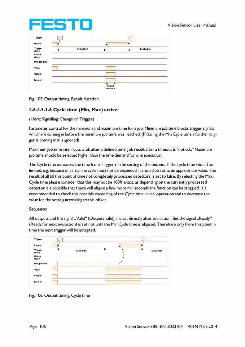
Page 106 Vision Sensor SBSI-EN, 8033104 - 1401N12.05.2014
Vision Sensor User manual
Fig. 105: Output timing, Result duration
4.6.4.5.1.6 Cycle time (Min, Max) active:
(Here: Signalling: Change on Trigger)
Parameter control for the minimum and maximum time for a job. Minimum job time blocks trigger signals
which are coming in before the minimum job time was reached. (If during the Min Cycle time a further trig-
ger is coming in it is ignored)
Maximum job time interrupts a job after a defined time. Job result after a timeout is "not o.k.” Maximum
job time should be selected higher than the time demand for one execution.
The Cycle time measures the time from Trigger till the setting of the outputs. If the cycle time should be
limited, e.g. because of a machine cycle must not be exceeded, it should be set to an appropriate value. The
result of all till this point of time not completely processed detectors is set to false. By selecting the Max.
Cycle time please consider that this may not be 100% exact, as depending on the currently processed
detector it´s possible that there will elapse a few more milliseconds the function can be stopped. It´s
recommended to check this possible exceeding of the Cycle time in real operation and to decrease the
value for the setting according to this offset.
Sequence:
All outputs and the signal „Valid“ (Outputs valid) are set directly after evaluation. But the signal „Ready“
(Ready for next evaluation) is set not until the Min Cycle time is elapsed. Therefore only from this point in
time the next trigger will be accepted.
Fig. 106: Output timing, Cycle time
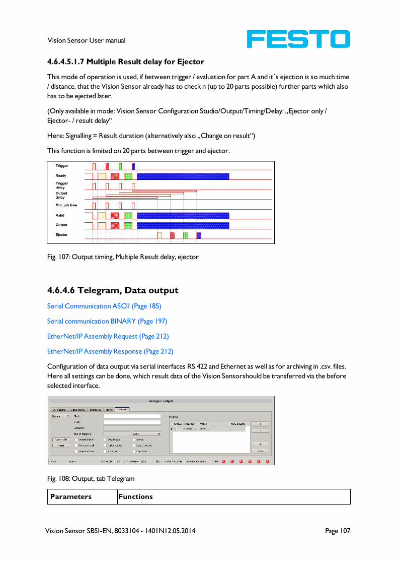
Vision Sensor SBSI-EN, 8033104 - 1401N12.05.2014 Page 107
Vision Sensor User manual
4.6.4.5.1.7 Multiple Result delay for Ejector
This mode of operation is used, if between trigger / evaluation for part A and it´s ejection is so much time
/ distance, that the Vision Sensor already has to check n (up to 20 parts possible) further parts which also
has to be ejected later.
(Only available in mode: Vision Sensor Configuration Studio/Output/Timing/Delay: „Ejector only /
Ejector- / result delay“
Here: Signalling = Result duration (alternatively also „Change on result“)
This function is limited on 20 parts between trigger and ejector.
Fig. 107: Output timing, Multiple Result delay, ejector
4.6.4.6 Telegram, Data output
Serial Communication ASCII (Page 185)
Serial communication BINARY (Page 197)
EtherNet/IP Assembly Request (Page 212)
EtherNet/IP Assembly Response (Page 212)
Configuration of data output via serial interfaces RS 422 and Ethernet as well as for archiving in .csv. files.
Here all settings can be done, which result data of the Vision Sensorshould be transferred via the before
selected interface.
Fig. 108: Output, tab Telegram
Parameters Functions

Page 108 Vision Sensor SBSI-EN, 8033104 - 1401N12.05.2014
Vision Sensor User manual
Binary / ASCII Output data in Binary- (Hex) or ASCII- format.
Save to file Exportation of file format with current results as .csv
Reset Reset of all parameters in this tab
Standard contents of protocol
Often required standard contents can be added to the output string by simply filling them in, or activation
via the checkbox.
StartCharacters which are inserted at the beginning of the payload data sting
(Binary or ASCII)
TrailerCharacters which are inserted at the end of the payload data sting (Binary
or ASCII)
Separator Characters which are inserted behind each payload value (ASCII only)
End of telegram
Characters which are sent at the end of a response to a PC or PLC (Reac-
tion to a command, not with payload data, in ASCII mode only, output
selectable in ANSI or Hexa Decimal)
Selected fields Shows which of the following checkboxes are activated.
.... further standard con-
tent, like e.g. “Selected
fields, Data length” ff.
to data string: „Payload“
Sequence: Selected fields, Data length, Status, Detector result, Digital out-
puts, Logical outputs, Execution time, Active job no., Checksum
Detector-specific individual results
First create a new entry by activating the "+" button.
Function of buttons
l "+": Insert new entry
l "-": Delete marked entry
l "Up", "Down": Displace marked entry
You can add detector-specific individual results to the data telegram in the required flexible order via the
selection list: (adding new values via button “+”)

Vision Sensor SBSI-EN, 8033104 - 1401N12.05.2014 Page 109
Vision Sensor User manual
Fig. 109: Output, Detector specific payload
Column Function
Active Activates/deactivates the marked output value
Detector Detector name (select from drop-down list)
Value Available detector results (select from drop-down menu)
Min.
length
Define the minimum length of the Value box; if the actual length is smaller than that specified,
the box is filled with spaces (ASCII) or zeros (binary)
4.6.4.6.1 Possibilities of data output of Vision Sensor (s. also User manual,
chap. Communication)
4.6.4.6.1.1 (Ethernet-) port 2005 / RS422
Numerical data, which has been defined under Output/Telegram, now can be transferred in ASCII- or Bin-
ary- format.
Ethernet: The sensor here is the (socket-) “server" and serves the Data via a „server-socket" interface.
This is basically a “programming interface”. To read or process the Data a “socket client" (PC, PLC, ....)
must establish a (socket-) connection (active) to the sensor.
4.6.4.6.1.2 PC-Archiving (Vision Sensor Visualisation Studio)
Here images and numeric result data (in .csv. format) can be stored by “Vision Sensor Visualisation Stu-
dio” into a folder on the PC.
The configuration (folder, …) of this archiving function is done via “Vision Sensor Visualisation Studio”.
(Menu: File/Result archiving, this is a pure PC- function)
4.6.4.6.1.3 Sensor- archiving (ftp, smb)
With this function images and numeric result data (in .csv format) can be stored actively by the sensor via
ftp/smb. This kind of archiving is configured under „Job/Archiving", in this case:
a) With „ftp“ used: the senor is a „ftp client" and „writes“ the data to a „ftp server" folder on a drive
which is available in the network. With Job/Start the sensor connects to the ftp-Server.
b) With „smb“ used: the sensor „writes“ the data direct in a folder in a network. With Job/Start the
sensor connects/mounts with this folder.
4.6.4.6.1.4 Ram disk (in the sensor)
In the sensor the last image as well as the numeric data of the last evaluation, which has been configured
under Output/Telegram, are stored (in a .csv file) in a Ram disc- folder under. „/tmp/results/".
This function is activated under „Job/Image transmission". To access this data an ftp- connection must be
established actively to the sensor. Therefore an ftp client is necessary.
Attention

Page 110 Vision Sensor SBSI-EN, 8033104 - 1401N12.05.2014
Vision Sensor User manual
* The format of the .csv files is always the same (ftp, smb, ram-disk, Vision Sensor Visualisation Studio).
* The data are stored readable (by default separated by comma) into the .csv file.
* Only payload data which has been defined under (Output/Telegram) are transferred.
4.6.4.6.2 Communication settings
Communication Ethernet RS422
To Sensor, Command Selectable in Tab: Protocol (Binary or ASCII)
From Sensor, Data output Selectable in Tab: Protocol (Binary or ASCII)
Protocol settings
Parameters Functions
Binary / ASCII Output data in Binary- (Hex) or ASCII- format.
Save to file Exportation of file format with current results as .csv
Reset Reset of all parameters in this tab
Basics for establishing of a connection:
Vision Sensor is always tcp/ip (socket-) server.
Vision Sensor sensor opens always two (socket-) communication ports (default: 2005 + 2006).
l 2005 = Data port for sending of numerical results.
l 2006 = Command port for receiving of commands.
At a time only one (socket-) client (PC or PLC) can be connected to a port.
Recommendations:
Existing socket connections have only to be reconnected, if an error occurred (on ports 2005 + 2006)
(e.g.: PLC or client in stop mode or error mode, etc.). During normal operation there is no need to recon-
nect existing connections.
Ethernet data handling: Especially if several Vision Sensor are used Ethernet should be preferred.
4.6.5 Result
With this function the defined job is processed in the PC, and the “Results/statistics” window with the
detector list and the evaluation results is displayed. The cycle times are not displayed in this mode as they
are not available from the sensor.
In “Run” mode the results of the detector marked in the detector list are displayed. In the image window
– if adjusted – the image, the search- and feature- frames, and the result- graphs are displayed
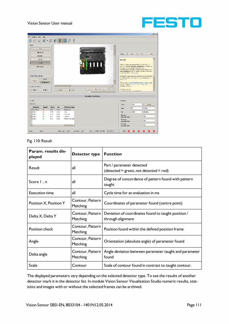
Vision Sensor SBSI-EN, 8033104 - 1401N12.05.2014 Page 111
Vision Sensor User manual
Fig. 110: Result
Param. results dis-
playedDetector type Function
Result allPart / parameter detected
(detected = green, not detected = red)
Score 1 .. n allDegree of concordance of pattern found with pattern
taught
Execution time all Cycle time for an evaluation in ms
Position X, Position YContour, Pattern
MatchingCoordinates of parameter found (centre point)
Delta X, Delta YContour, Pattern
Matching
Deviation of coordinates found to taught position /
through alignment
Position checkContour, Pattern
MatchingPosition found within the defined position frame
AngleContour, Pattern
MatchingOrientation (absolute angle) of parameter found
Delta angleContour, Pattern
Matching
Angle deviation between parameter taught and parameter
found
Scale Contour Scale of contour found in contrast to taught contour.
The displayed parameters vary depending on the selected detector type. To see the results of another
detector mark it in the detector list. In module Vision Sensor Visualisation Studio numeric results, stat-
istics and images with or without the selected frames can be archived.
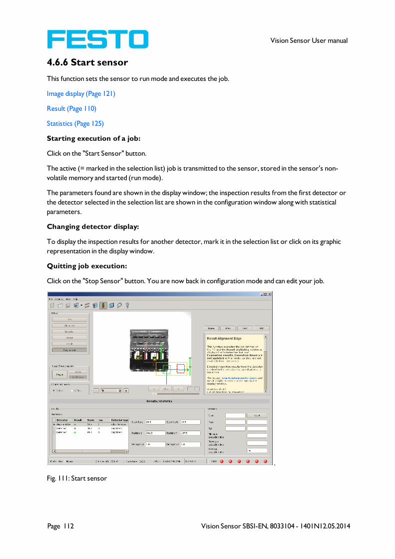
Page 112 Vision Sensor SBSI-EN, 8033104 - 1401N12.05.2014
Vision Sensor User manual
4.6.6 Start sensor
This function sets the sensor to run mode and executes the job.
Image display (Page 121)
Result (Page 110)
Statistics (Page 125)
Starting execution of a job:
Click on the "Start Sensor" button.
The active (= marked in the selection list) job is transmitted to the sensor, stored in the sensor's non-
volatile memory and started (run mode).
The parameters found are shown in the display window; the inspection results from the first detector or
the detector selected in the selection list are shown in the configuration window along with statistical
parameters.
Changing detector display:
To display the inspection results for another detector, mark it in the selection list or click on its graphic
representation in the display window.
Quitting job execution:
Click on the "Stop Sensor" button. You are now back in configuration mode and can edit your job.
.
Fig. 111: Start sensor
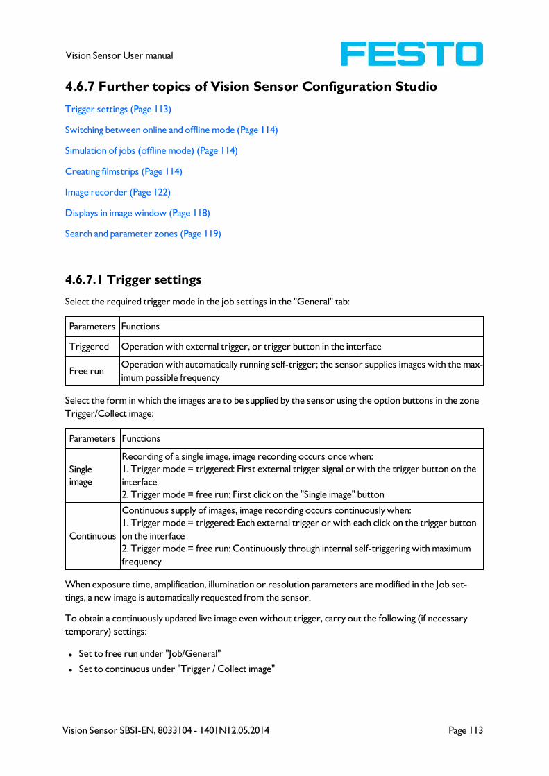
Vision Sensor SBSI-EN, 8033104 - 1401N12.05.2014 Page 113
Vision Sensor User manual
4.6.7 Further topics of Vision Sensor Configuration Studio
Trigger settings (Page 113)
Switching between online and offline mode (Page 114)
Simulation of jobs (offline mode) (Page 114)
Creating filmstrips (Page 114)
Image recorder (Page 122)
Displays in image window (Page 118)
Search and parameter zones (Page 119)
4.6.7.1 Trigger settings
Select the required trigger mode in the job settings in the "General" tab:
Parameters Functions
Triggered Operation with external trigger, or trigger button in the interface
Free runOperation with automatically running self-trigger; the sensor supplies images with the max-
imum possible frequency
Select the form in which the images are to be supplied by the sensor using the option buttons in the zone
Trigger/Collect image:
Parameters Functions
Single
image
Recording of a single image, image recording occurs once when:
1. Trigger mode = triggered: First external trigger signal or with the trigger button on the
interface
2. Trigger mode = free run: First click on the "Single image" button
Continuous
Continuous supply of images, image recording occurs continuously when:
1. Trigger mode = triggered: Each external trigger or with each click on the trigger button
on the interface
2. Trigger mode = free run: Continuously through internal self-triggering with maximum
frequency
When exposure time, amplification, illumination or resolution parameters are modified in the Job set-
tings, a new image is automatically requested from the sensor.
To obtain a continuously updated live image even without trigger, carry out the following (if necessary
temporary) settings:
l Set to free run under "Job/General"
l Set to continuous under "Trigger / Collect image"
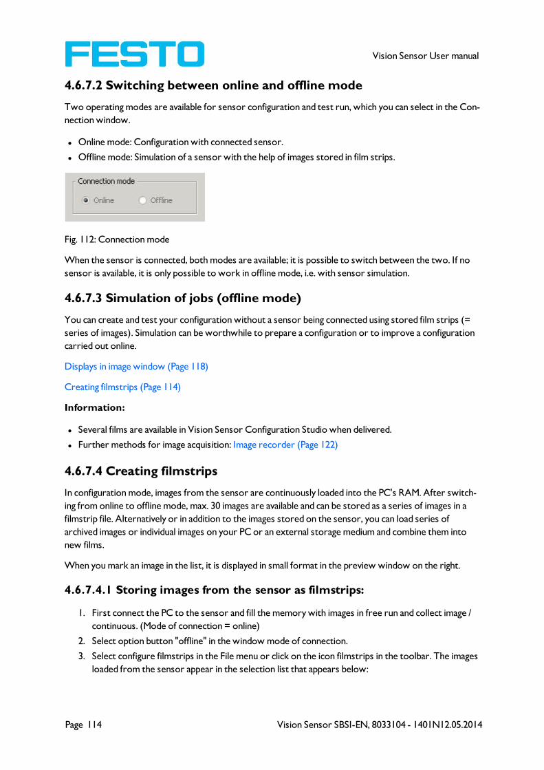
Page 114 Vision Sensor SBSI-EN, 8033104 - 1401N12.05.2014
Vision Sensor User manual
4.6.7.2 Switching between online and offline mode
Two operating modes are available for sensor configuration and test run, which you can select in the Con-
nection window.
l Online mode: Configuration with connected sensor.
l Offline mode: Simulation of a sensor with the help of images stored in film strips.
Fig. 112: Connection mode
When the sensor is connected, both modes are available; it is possible to switch between the two. If no
sensor is available, it is only possible to work in offline mode, i.e. with sensor simulation.
4.6.7.3 Simulation of jobs (offline mode)
You can create and test your configuration without a sensor being connected using stored film strips (=
series of images). Simulation can be worthwhile to prepare a configuration or to improve a configuration
carried out online.
Displays in image window (Page 118)
Creating filmstrips (Page 114)
Information:
l Several films are available in Vision Sensor Configuration Studio when delivered.
l Further methods for image acquisition: Image recorder (Page 122)
4.6.7.4 Creating filmstrips
In configuration mode, images from the sensor are continuously loaded into the PC's RAM. After switch-
ing from online to offline mode, max. 30 images are available and can be stored as a series of images in a
filmstrip file. Alternatively or in addition to the images stored on the sensor, you can load series of
archived images or individual images on your PC or an external storage medium and combine them into
new films.
When you mark an image in the list, it is displayed in small format in the preview window on the right.
4.6.7.4.1 Storing images from the sensor as filmstrips:
1. First connect the PC to the sensor and fill the memory with images in free run and collect image /
continuous. (Mode of connection = online)
2. Select option button "offline" in the window mode of connection.
3. Select configure filmstrips in the File menu or click on the icon filmstrips in the toolbar. The images
loaded from the sensor appear in the selection list that appears below:
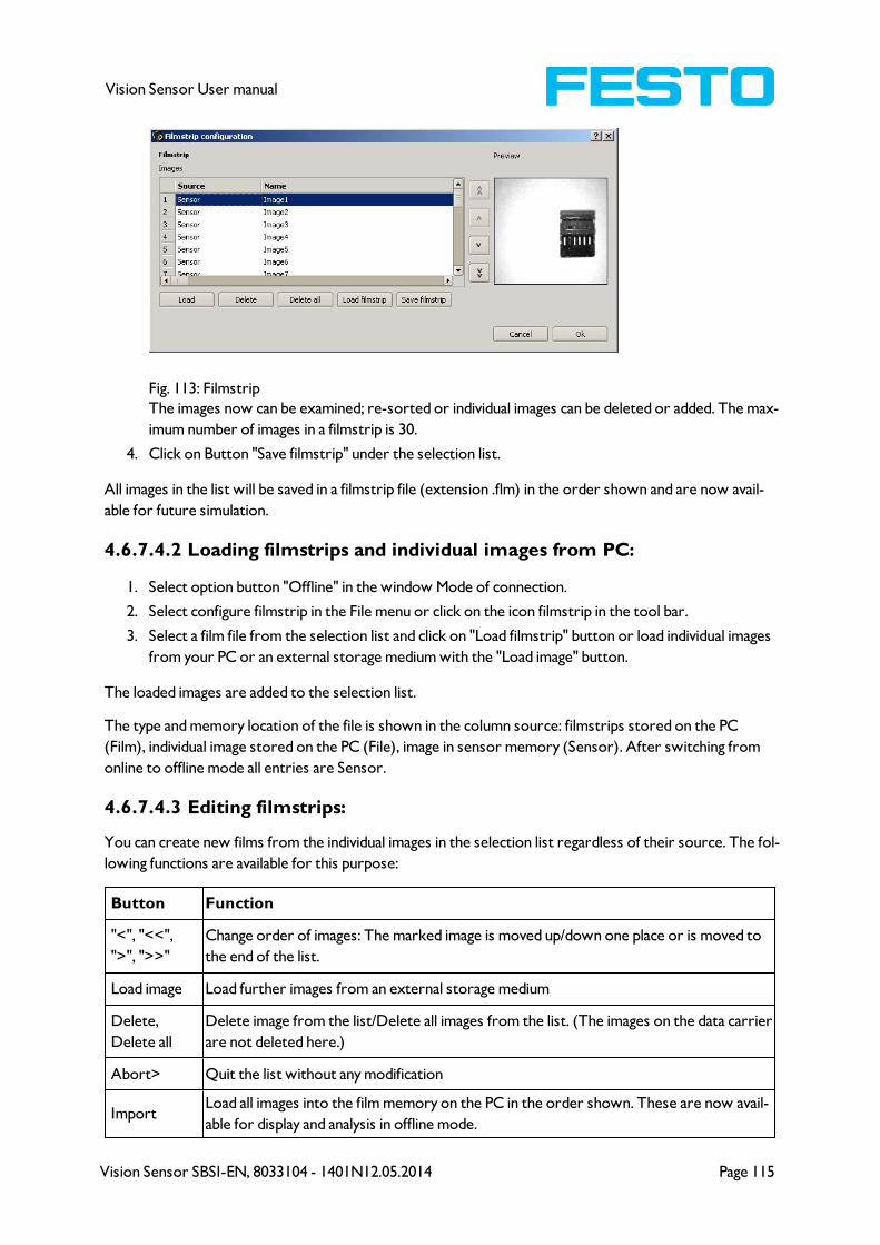
Vision Sensor SBSI-EN, 8033104 - 1401N12.05.2014 Page 115
Vision Sensor User manual
Fig. 113: Filmstrip
The images now can be examined; re-sorted or individual images can be deleted or added. The max-
imum number of images in a filmstrip is 30.
4. Click on Button "Save filmstrip" under the selection list.
All images in the list will be saved in a filmstrip file (extension .flm) in the order shown and are now avail-
able for future simulation.
4.6.7.4.2 Loading filmstrips and individual images from PC:
1. Select option button "Offline" in the window Mode of connection.
2. Select configure filmstrip in the File menu or click on the icon filmstrip in the tool bar.
3. Select a film file from the selection list and click on "Load filmstrip" button or load individual images
from your PC or an external storage medium with the "Load image" button.
The loaded images are added to the selection list.
The type and memory location of the file is shown in the column source: filmstrips stored on the PC
(Film), individual image stored on the PC (File), image in sensor memory (Sensor). After switching from
online to offline mode all entries are Sensor.
4.6.7.4.3 Editing filmstrips:
You can create new films from the individual images in the selection list regardless of their source. The fol-
lowing functions are available for this purpose:
Button Function
"<", "<<",
">", ">>"
Change order of images: The marked image is moved up/down one place or is moved to
the end of the list.
Load image Load further images from an external storage medium
Delete,
Delete all
Delete image from the list/Delete all images from the list. (The images on the data carrier
are not deleted here.)
Abort> Quit the list without any modification
ImportLoad all images into the film memory on the PC in the order shown. These are now avail-
able for display and analysis in offline mode.
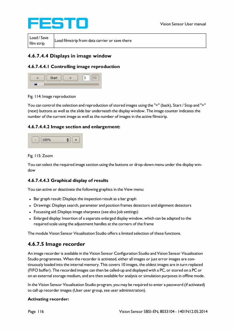
Page 116 Vision Sensor SBSI-EN, 8033104 - 1401N12.05.2014
Vision Sensor User manual
Load / Save
film stripLoad filmstrip from data carrier or save there
4.6.7.4.4 Displays in image window
4.6.7.4.4.1 Controlling image reproduction
Fig. 114: Image reproduction
You can control the selection and reproduction of stored images using the "<" (back), Start / Stop and ">"
(next) buttons as well as the slide bar underneath the display window. The image counter indicates the
number of the current image as well as the number of images in the active filmstrip.
4.6.7.4.4.2 Image section and enlargement:
Fig. 115: Zoom
You can select the required image section using the buttons or drop-down menu under the display win-
dow
4.6.7.4.4.3 Graphical display of results
You can active or deactivate the following graphics in the View menu:
l Bar graph result: Displays the inspection result as a bar graph
l Drawings: Displays search, parameter and position frames detectors and alignment detectors
l Focussing aid: Displays image sharpness (see also Job settings)
l Enlarged display: Insertion of a separate enlarged display window, which can be adapted to the
required scale using the adjustment handles at the corners of the frame
The module Vision Sensor Visualisation Studio offers a limited selection of these functions.
4.6.7.5 Image recorder
An image recorder is available in the Vision Sensor Configuration Studio and Vision Sensor Visualisation
Studio programmes. When the recorder is activated, either all images or just error images are con-
tinuously loaded into the internal memory. This covers 10 images, the oldest images are in turn replaced
(FIFO buffer). The recorded images can then be called-up and displayed with a PC, or stored on a PC or
on an external storage medium, and are then available for analysis or simulation purposes in offline mode.
In the Vision Sensor Visualisation Studio program, you may be required to enter a password (if activated)
to call up recorder images (User user group, see user administration).
Activating recorder:
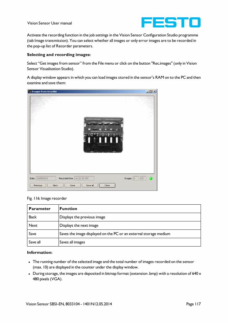
Vision Sensor SBSI-EN, 8033104 - 1401N12.05.2014 Page 117
Vision Sensor User manual
Activate the recording function in the job settings in the Vision Sensor Configuration Studio programme
(tab Image transmission). You can select whether all images or only error images are to be recorded in
the pop-up list of Recorder parameters.
Selecting and recording images:
Select “Get images from sensor” from the File menu or click on the button "Rec.images" (only in Vision
Sensor Visualisation Studio).
A display window appears in which you can load images stored in the sensor's RAM on to the PC and then
examine and save them:
Fig. 116: Image recorder
Parameter Function
Back Displays the previous image
Next Displays the next image
Save Saves the image displayed on the PC or an external storage medium
Save all Saves all images
Information:
l The running number of the selected image and the total number of images recorded on the sensor
(max. 10) are displayed in the counter under the display window.
l During storage, the images are deposited in bitmap format (extension .bmp) with a resolution of 640 x
480 pixels (VGA).
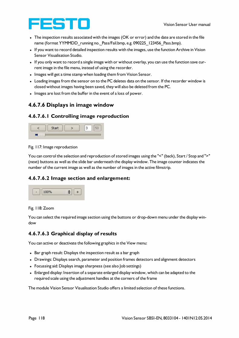
Page 118 Vision Sensor SBSI-EN, 8033104 - 1401N12.05.2014
Vision Sensor User manual
l The inspection results associated with the images (OK or error) and the date are stored in the file
name (format YYMMDD_running no._Pass/Fail.bmp, e.g. 090225_123456_Pass.bmp).
l If you want to record detailed inspection results with the images, use the function Archive in Vision
Sensor Visualisation Studio.
l If you only want to record a single image with or without overlay, you can use the function save cur-
rent image in the file menu, instead of using the recorder.
l Images will get a time stamp when loading them from Vision Sensor.
l Loading images from the sensor on to the PC deletes data on the sensor. If the recorder window is
closed without images having been saved, they will also be deleted from the PC.
l Images are lost from the buffer in the event of a loss of power.
4.6.7.6 Displays in image window
4.6.7.6.1 Controlling image reproduction
Fig. 117: Image reproduction
You can control the selection and reproduction of stored images using the "<" (back), Start / Stop and ">"
(next) buttons as well as the slide bar underneath the display window. The image counter indicates the
number of the current image as well as the number of images in the active filmstrip.
4.6.7.6.2 Image section and enlargement:
Fig. 118: Zoom
You can select the required image section using the buttons or drop-down menu under the display win-
dow
4.6.7.6.3 Graphical display of results
You can active or deactivate the following graphics in the View menu:
l Bar graph result: Displays the inspection result as a bar graph
l Drawings: Displays search, parameter and position frames detectors and alignment detectors
l Focussing aid: Displays image sharpness (see also Job settings)
l Enlarged display: Insertion of a separate enlarged display window, which can be adapted to the
required scale using the adjustment handles at the corners of the frame
The module Vision Sensor Visualisation Studio offers a limited selection of these functions.

Vision Sensor SBSI-EN, 8033104 - 1401N12.05.2014 Page 119
Vision Sensor User manual
4.6.7.7 Search and parameter zones
You can define search and parameter zones in the configuration steps alignment and detectors. These are
identified in the image window by different coloured frames.
Drawings in the screen (yellow, red frames etc.) can be activated or deactivated for any detector or cat-
egory in the menu item "View/all drawings". With "View/drawings of current detector only", all drawings
on the screen can be deactivated with the exception of the detector currently being processed.
4.6.7.7.1 Definition of search and parameter zones
When a new detector is created, a yellow frame is displayed, which defines the detector's search zone.
The standard shape of the search zone is a rectangle; with contrast and grey level detectors, a circle can
also be selected. The defined parameters (red frame) are found (green frame) provided its centre is
within the search zone (yellow frame).
With pattern matching and contour detection detectors, there is also a parameter zone within the search
zone which is represented by a red or green frame:
l Red frame = teach parameters
l Green frame = parameters found
If position control / check is defined, a blue frame appears also (either a rectangle, circle or ellipse).
If an alignment detector is defined, it's frame is shown in dotted yellow lines.
At the according upper left corner of each frame the number of the detector is shown.
4.6.7.7.2 Adapting search and parameter zones
The zones initially displayed in standard size and position can be selected / marked in the image or in the
detector list and altered in size and position. Eight adjustment handles on the frame enable you to adapt
the shape and size of the frame. Its position can be displaced by clicking anywhere inside the frame. The
arrow at the side of the frame pointing to the centre can be used to change the rotational position of the
frame.
The taught sample is represented in original size in the General or Parameters tab in the bottom, right-
hand corner of the screen. Only the frame of the currently active detector, selected in the image or
detector list, is shown with thick lines and adjustment handles, all other frames which are not selected are
shown with thin or dotted lines (alignment detector).
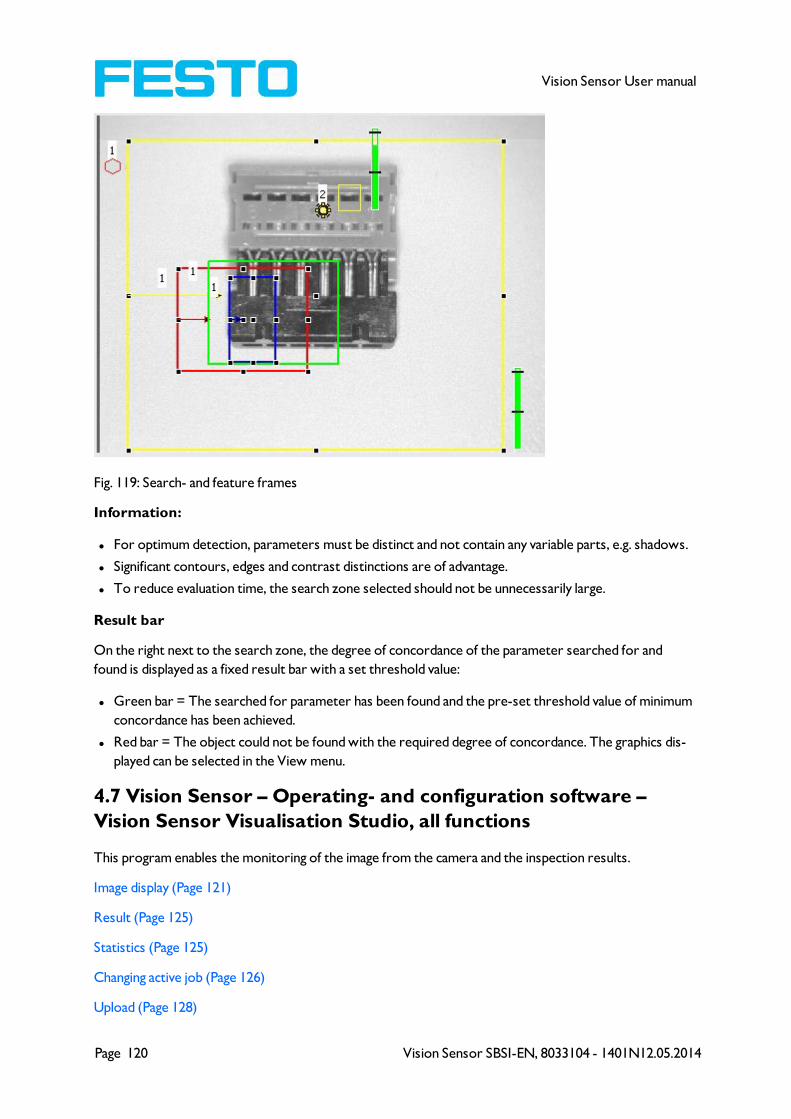
Page 120 Vision Sensor SBSI-EN, 8033104 - 1401N12.05.2014
Vision Sensor User manual
Fig. 119: Search- and feature frames
Information:
l For optimum detection, parameters must be distinct and not contain any variable parts, e.g. shadows.
l Significant contours, edges and contrast distinctions are of advantage.
l To reduce evaluation time, the search zone selected should not be unnecessarily large.
Result bar
On the right next to the search zone, the degree of concordance of the parameter searched for and
found is displayed as a fixed result bar with a set threshold value:
l Green bar = The searched for parameter has been found and the pre-set threshold value of minimum
concordance has been achieved.
l Red bar = The object could not be found with the required degree of concordance. The graphics dis-
played can be selected in the View menu.
4.7 Vision Sensor – Operating- and configuration software –
Vision Sensor Visualisation Studio, all functions
This program enables the monitoring of the image from the camera and the inspection results.
Image display (Page 121)
Result (Page 125)
Statistics (Page 125)
Changing active job (Page 126)
Upload (Page 128)
Vision Sensor SBSI-EN, 8033104 - 1401N12.05.2014 Page 121
Vision Sensor User manual
Commands / Freeze image (Page 122)
Image recorder (Page 122)
Archiving test results and images (Page 124)
From this software ONLY monitoring and job change (loading of already defined jobs) can be done. It can
be password protected so that you can only view (worker level), or view and load predefined jobs (Super-
Vision Sensor level)
4.7.1 Image display
The graphical display of an image and the inspection results in the display window depend on the setting of
the parameter Image transmission in job settings (Parameters for image transmission (Page 52) in Vision
Sensor Configuration Studio) program:
l Image transmission active: The current image along with the frames for the defined search, parameter
and position zones and parameters found are displayed.
l Image transmission inactive: Only the frames for the defined search, parameter and position zones and
parameters found are displayed (current image is not displayed).
The degree of concordance between the parameter searched for and the parameter found appears to the
right next to the search zone of the respective detector, in the form of a vertical result bar with a set
threshold value:
l Green bar: The parameter searched for has been found and the pre-set threshold value for con-
cordance has been reached.
l Red bar: The object could not be found with the required degree of concordance.
An exclamation mark in the top right hand corner of the live picture means, that image processing on PC
is slower than image processing on Vision Sensor
. i.e. Not all images are transferred to PC.
This may cause lost images in images archiving. If this symbol occurs often, PC-programs running in back-
ground should be closed in order to improve PC performance.
You can configure the graphics of the inspection results in the View menu.
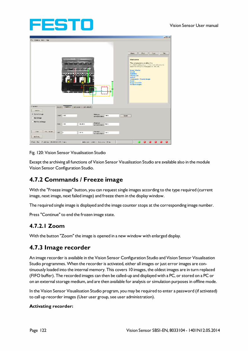
Page 122 Vision Sensor SBSI-EN, 8033104 - 1401N12.05.2014
Vision Sensor User manual
Fig. 120: Vision Sensor Visualisation Studio
Except the archiving all functions of Vision Sensor Visualisation Studio are available also in the module
Vision Sensor Configuration Studio.
4.7.2 Commands / Freeze image
With the "Freeze image" button, you can request single images according to the type required (current
image, next image, next failed image) and freeze them in the display window.
The required single image is displayed and the image counter stops at the corresponding image number.
Press "Continue" to end the frozen image state.
4.7.2.1 Zoom
With the button "Zoom" the image is opened in a new window with enlarged display.
4.7.3 Image recorder
An image recorder is available in the Vision Sensor Configuration Studio and Vision Sensor Visualisation
Studio programmes. When the recorder is activated, either all images or just error images are con-
tinuously loaded into the internal memory. This covers 10 images, the oldest images are in turn replaced
(FIFO buffer). The recorded images can then be called-up and displayed with a PC, or stored on a PC or
on an external storage medium, and are then available for analysis or simulation purposes in offline mode.
In the Vision Sensor Visualisation Studio program, you may be required to enter a password (if activated)
to call up recorder images (User user group, see user administration).
Activating recorder:

Vision Sensor SBSI-EN, 8033104 - 1401N12.05.2014 Page 123
Vision Sensor User manual
Activate the recording function in the job settings in the Vision Sensor Configuration Studio programme
(tab Image transmission). You can select whether all images or only error images are to be recorded in
the pop-up list of Recorder parameters.
Selecting and recording images:
Select “Get images from sensor” from the File menu or click on the button "Rec.images" (only in Vision
Sensor Visualisation Studio).
A display window appears in which you can load images stored in the sensor's RAM on to the PC and then
examine and save them:
Fig. 121: Image recorder
Parameter Function
Back Displays the previous image
Next Displays the next image
Save Saves the image displayed on the PC or an external storage medium
Save all Saves all images
Information:
l The running number of the selected image and the total number of images recorded on the sensor
(max. 10) are displayed in the counter under the display window.
l During storage, the images are deposited in bitmap format (extension .bmp) with a resolution of 640 x
480 pixels (VGA).
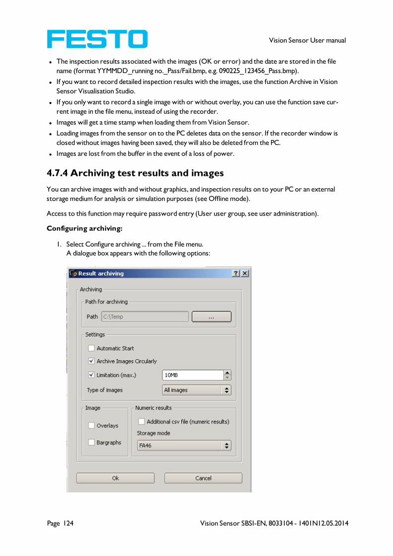
Page 124 Vision Sensor SBSI-EN, 8033104 - 1401N12.05.2014
Vision Sensor User manual
l The inspection results associated with the images (OK or error) and the date are stored in the file
name (format YYMMDD_running no._Pass/Fail.bmp, e.g. 090225_123456_Pass.bmp).
l If you want to record detailed inspection results with the images, use the function Archive in Vision
Sensor Visualisation Studio.
l If you only want to record a single image with or without overlay, you can use the function save cur-
rent image in the file menu, instead of using the recorder.
l Images will get a time stamp when loading them from Vision Sensor.
l Loading images from the sensor on to the PC deletes data on the sensor. If the recorder window is
closed without images having been saved, they will also be deleted from the PC.
l Images are lost from the buffer in the event of a loss of power.
4.7.4 Archiving test results and images
You can archive images with and without graphics, and inspection results on to your PC or an external
storage medium for analysis or simulation purposes (see Offline mode).
Access to this function may require password entry (User user group, see user administration).
Configuring archiving:
1. Select Configure archiving ... from the File menu.
A dialogue box appears with the following options:
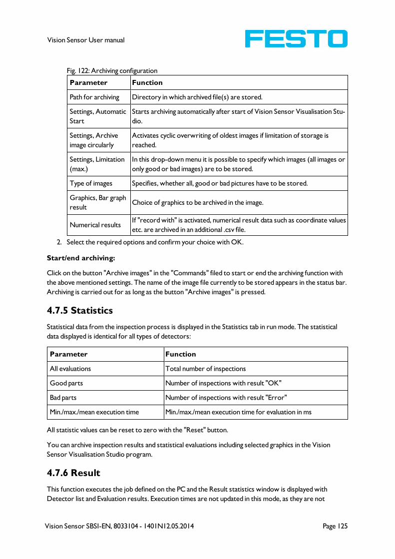
Vision Sensor SBSI-EN, 8033104 - 1401N12.05.2014 Page 125
Vision Sensor User manual
Fig. 122: Archiving configuration
Parameter Function
Path for archiving Directory in which archived file(s) are stored.
Settings, Automatic
Start
Starts archiving automatically after start of Vision Sensor Visualisation Stu-
dio.
Settings, Archive
image circularly
Activates cyclic overwriting of oldest images if limitation of storage is
reached.
Settings, Limitation
(max.)
In this drop-down menu it is possible to specify which images (all images or
only good or bad images) are to be stored.
Type of images Specifies, whether all, good or bad pictures have to be stored.
Graphics, Bar graph
resultChoice of graphics to be archived in the image.
Numerical resultsIf "record with" is activated, numerical result data such as coordinate values
etc. are archived in an additional .csv file.
2. Select the required options and confirm your choice with OK.
Start/end archiving:
Click on the button "Archive images" in the "Commands" filed to start or end the archiving function with
the above mentioned settings. The name of the image file currently to be stored appears in the status bar.
Archiving is carried out for as long as the button "Archive images" is pressed.
4.7.5 Statistics
Statistical data from the inspection process is displayed in the Statistics tab in run mode. The statistical
data displayed is identical for all types of detectors:
Parameter Function
All evaluations Total number of inspections
Good parts Number of inspections with result "OK"
Bad parts Number of inspections with result "Error"
Min./max./mean execution time Min./max./mean execution time for evaluation in ms
All statistic values can be reset to zero with the "Reset" button.
You can archive inspection results and statistical evaluations including selected graphics in the Vision
Sensor Visualisation Studio program.
4.7.6 Result
This function executes the job defined on the PC and the Result statistics window is displayed with
Detector list and Evaluation results. Execution times are not updated in this mode, as they are not
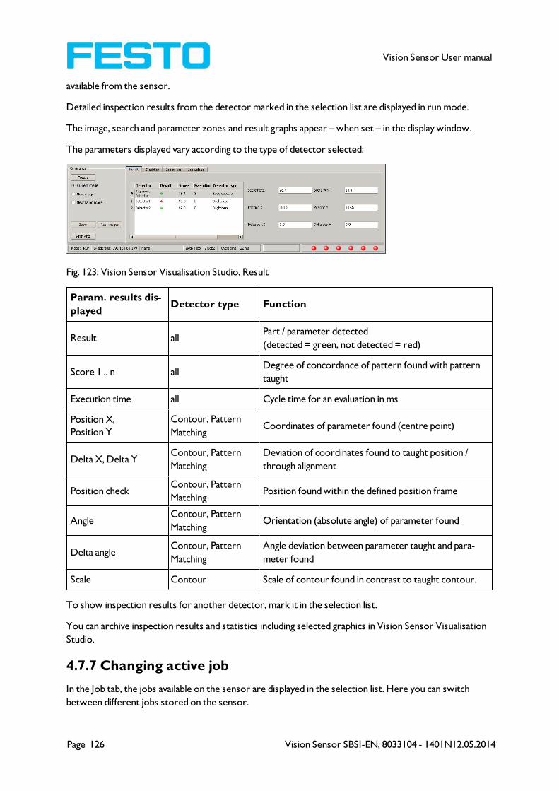
Page 126 Vision Sensor SBSI-EN, 8033104 - 1401N12.05.2014
Vision Sensor User manual
available from the sensor.
Detailed inspection results from the detector marked in the selection list are displayed in run mode.
The image, search and parameter zones and result graphs appear – when set – in the display window.
The parameters displayed vary according to the type of detector selected:
Fig. 123: Vision Sensor Visualisation Studio, Result
Param. results dis-
playedDetector type Function
Result allPart / parameter detected
(detected = green, not detected = red)
Score 1 .. n allDegree of concordance of pattern found with pattern
taught
Execution time all Cycle time for an evaluation in ms
Position X,
Position Y
Contour, Pattern
MatchingCoordinates of parameter found (centre point)
Delta X, Delta YContour, Pattern
Matching
Deviation of coordinates found to taught position /
through alignment
Position checkContour, Pattern
MatchingPosition found within the defined position frame
AngleContour, Pattern
MatchingOrientation (absolute angle) of parameter found
Delta angleContour, Pattern
Matching
Angle deviation between parameter taught and para-
meter found
Scale Contour Scale of contour found in contrast to taught contour.
To show inspection results for another detector, mark it in the selection list.
You can archive inspection results and statistics including selected graphics in Vision Sensor Visualisation
Studio.
4.7.7 Changing active job
In the Job tab, the jobs available on the sensor are displayed in the selection list. Here you can switch
between different jobs stored on the sensor.
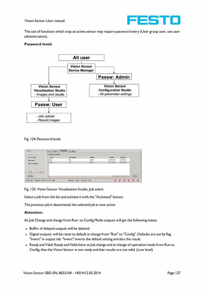
Vision Sensor SBSI-EN, 8033104 - 1401N12.05.2014 Page 127
Vision Sensor User manual
The use of functions which stop an active sensor may require password entry (User group user, see user
administration).
Password levels
Fig. 124: Password levels
Fig. 125: Vision Sensor Visualisation Studio, Job select
Select a job from the list and activate it with the "Activated" button.
The previous job is deactivated; the selected job is now active.
Attention:
At Job Change and change from Run- to Config Mode outputs will get the following states:
l Buffer of delayed outputs will be deleted.
l Digital outputs: will be reset to default at change from "Run" to "Config". Defaults are set by flag
"Invert" in output tab. "Invert" inverts the default setting and also the result.
l Ready and Valid: Ready and Valid show at Job change and at change of operation mode from Run to
Config, that the Vision Sensor is not ready and that results are not valid. (Low level)
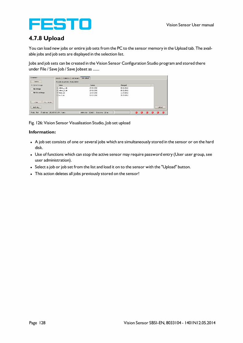
Page 128 Vision Sensor SBSI-EN, 8033104 - 1401N12.05.2014
Vision Sensor User manual
4.7.8 Upload
You can load new jobs or entire job sets from the PC to the sensor memory in the Upload tab. The avail-
able jobs and job sets are displayed in the selection list.
Jobs and job sets can be created in the Vision Sensor Configuration Studio program and stored there
under File / Save Job / Save Jobset as .......
Fig. 126: Vision Sensor Visualisation Studio, Job set upload
Information:
l A job set consists of one or several jobs which are simultaneously stored in the sensor or on the hard
disk.
l Use of functions which can stop the active sensor may require password entry (User user group, see
user administration).
l Select a job or job set from the list and load it on to the sensor with the "Upload" button.
l This action deletes all jobs previously stored on the sensor!
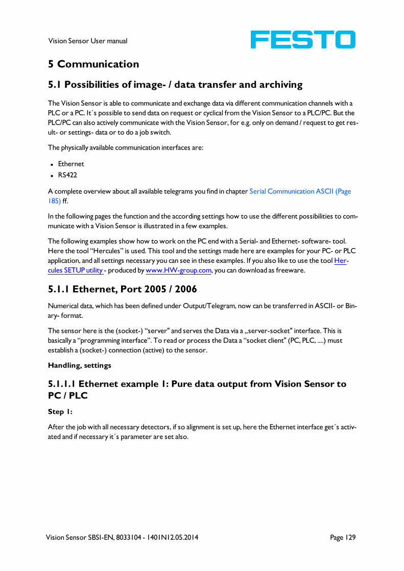
Vision Sensor SBSI-EN, 8033104 - 1401N12.05.2014 Page 129
Vision Sensor User manual
5 Communication
5.1 Possibilities of image- / data transfer and archiving
The Vision Sensor is able to communicate and exchange data via different communication channels with a
PLC or a PC. It´s possible to send data on request or cyclical from the Vision Sensor to a PLC/PC. But the
PLC/PC can also actively communicate with the Vision Sensor, for e.g. only on demand / request to get res-
ult- or settings- data or to do a job switch.
The physically available communication interfaces are:
l Ethernet
l RS422
A complete overview about all available telegrams you find in chapter Serial Communication ASCII (Page
185) ff.
In the following pages the function and the according settings how to use the different possibilities to com-
municate with a Vision Sensor is illustrated in a few examples.
The following examples show how to work on the PC end with a Serial- and Ethernet- software- tool.
Here the tool “Hercules” is used. This tool and the settings made here are examples for your PC- or PLC
application, and all settings necessary you can see in these examples. If you also like to use the tool Her-
cules SETUP utility - produced by www.HW-group.com, you can download as freeware.
5.1.1 Ethernet, Port 2005 / 2006
Numerical data, which has been defined under Output/Telegram, now can be transferred in ASCII- or Bin-
ary- format.
The sensor here is the (socket-) “server" and serves the Data via a „server-socket" interface. This is
basically a “programming interface”. To read or process the Data a “socket client" (PC, PLC, ....) must
establish a (socket-) connection (active) to the sensor.
Handling, settings
5.1.1.1 Ethernet example 1: Pure data output from Vision Sensor to
PC / PLC
Step 1:
After the job with all necessary detectors, if so alignment is set up, here the Ethernet interface get´s activ-
ated and if necessary it´s parameter are set also.
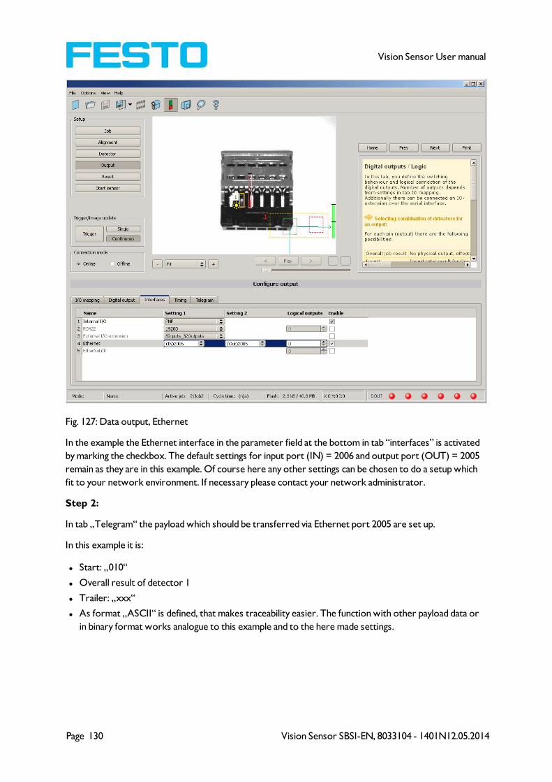
Page 130 Vision Sensor SBSI-EN, 8033104 - 1401N12.05.2014
Vision Sensor User manual
Fig. 127: Data output, Ethernet
In the example the Ethernet interface in the parameter field at the bottom in tab “interfaces” is activated
by marking the checkbox. The default settings for input port (IN) = 2006 and output port (OUT) = 2005
remain as they are in this example. Of course here any other settings can be chosen to do a setup which
fit to your network environment. If necessary please contact your network administrator.
Step 2:
In tab „Telegram“ the payload which should be transferred via Ethernet port 2005 are set up.
In this example it is:
l Start: „010“
l Overall result of detector 1
l Trailer: „xxx“
l As format „ASCII“ is defined, that makes traceability easier. The function with other payload data or
in binary format works analogue to this example and to the here made settings.
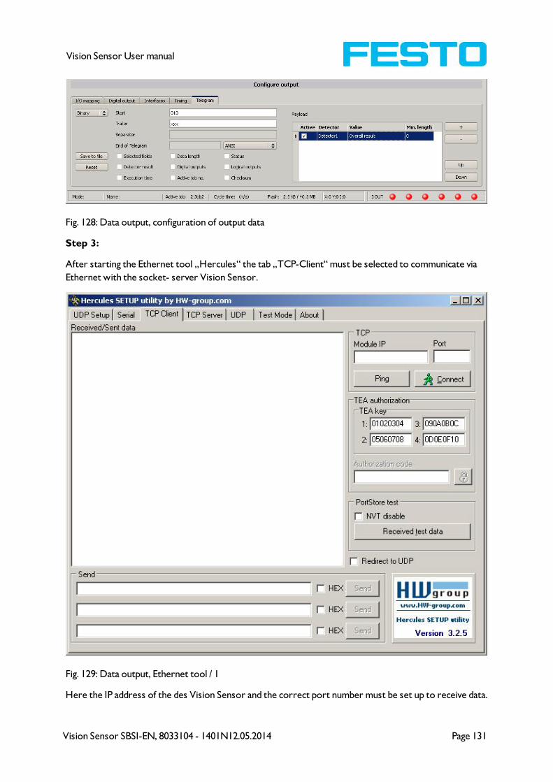
Vision Sensor SBSI-EN, 8033104 - 1401N12.05.2014 Page 131
Vision Sensor User manual
Fig. 128: Data output, configuration of output data
Step 3:
After starting the Ethernet tool „Hercules“ the tab „TCP-Client“ must be selected to communicate via
Ethernet with the socket- server Vision Sensor.
Fig. 129: Data output, Ethernet tool / 1
Here the IP address of the des Vision Sensor and the correct port number must be set up to receive data.
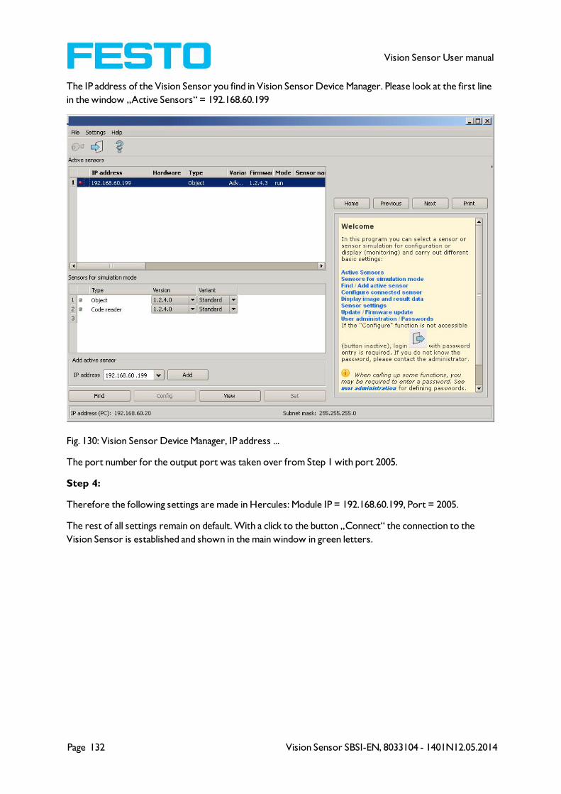
Page 132 Vision Sensor SBSI-EN, 8033104 - 1401N12.05.2014
Vision Sensor User manual
The IP address of the Vision Sensor you find in Vision Sensor Device Manager. Please look at the first line
in the window „Active Sensors“ = 192.168.60.199
Fig. 130: Vision Sensor Device Manager, IP address ...
The port number for the output port was taken over from Step 1 with port 2005.
Step 4:
Therefore the following settings are made in Hercules: Module IP = 192.168.60.199, Port = 2005.
The rest of all settings remain on default. With a click to the button „Connect“ the connection to the
Vision Sensor is established and shown in the main window in green letters.

Vision Sensor SBSI-EN, 8033104 - 1401N12.05.2014 Page 133
Vision Sensor User manual
Fig. 131: Figure 168 Data output, Ethernet Tool / 2
Step 5:
The Vision Sensornow needs to be started form the PC application with „Start sensor“. (Later in
autonomous operation the Vision Sensor directly starts after power on, and sends data, if configured this
way).
In the example Trigger mode is “Continuous”, that means evaluation is done continuously and data is sent
continuously too. All this data is visible in the main window of Hercules.
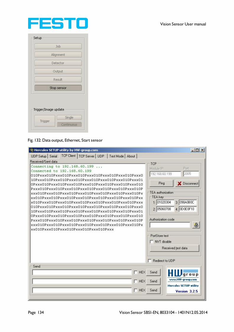
Page 134 Vision Sensor SBSI-EN, 8033104 - 1401N12.05.2014
Vision Sensor User manual
Fig. 132: Data output, Ethernet, Start sensor
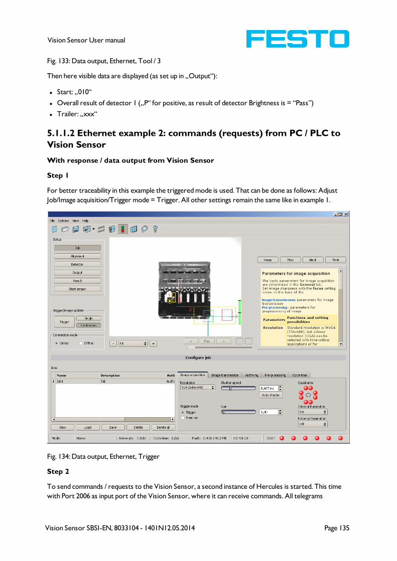
Vision Sensor SBSI-EN, 8033104 - 1401N12.05.2014 Page 135
Vision Sensor User manual
Fig. 133: Data output, Ethernet, Tool / 3
Then here visible data are displayed (as set up in „Output“):
l Start: „010“
l Overall result of detector 1 („P“ for positive, as result of detector Brightness is = “Pass”)
l Trailer: „xxx“
5.1.1.2 Ethernet example 2: commands (requests) from PC / PLC to
Vision Sensor
With response / data output from Vision Sensor
Step 1
For better traceability in this example the triggered mode is used. That can be done as follows: Adjust
Job/Image acquisition/Trigger mode = Trigger. All other settings remain the same like in example 1.
Fig. 134: Data output, Ethernet, Trigger
Step 2
To send commands / requests to the Vision Sensor, a second instance of Hercules is started. This time
with Port 2006 as input port of the Vision Sensor, where it can receive commands. All telegrams
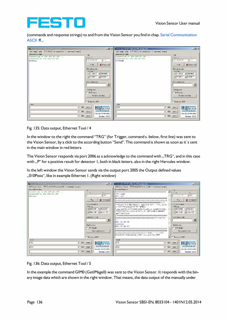
Page 136 Vision Sensor SBSI-EN, 8033104 - 1401N12.05.2014
Vision Sensor User manual
(commands and response strings) to and from the Vision Sensor you find in chap. Serial Communication
ASCII ff...
Fig. 135: Data output, Ethernet Tool / 4
In the window to the right the command “TRG” (for Trigger, command s. below, first line) was sent to
the Vision Sensor, by a click to the according button “Send”. This command is shown as soon as it´s sent
in the main window in red letters.
The Vision Sensor responds via port 2006 as a acknowledge to the command with „TRG“, and in this case
with „P“ for a positive result for detector 1, both in black letters, also in the right Hercules window.
In the left window the Vision Sensor sends via the output port 2005 the Output defined values
„010Pxxx“, like in example Ethernet 1. (Right window)
Fig. 136: Data output, Ethernet Tool / 5
In the example the command GIM0 (GetIMage0) was sent to the Vision Sensor. It responds with the bin-
ary image data which are shown in the right window. That means, the data output of the manually under
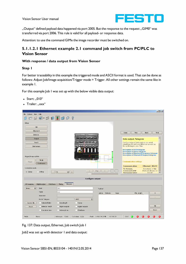
Vision Sensor SBSI-EN, 8033104 - 1401N12.05.2014 Page 137
Vision Sensor User manual
„Output“ defined payload data happened via port 2005. But the response to the request „GIM0“ was
transferred via port 2006. This rule is valid for all payload- or response data.
Attention: to use the command GIMx the image recorder must be switched on.
5.1.1.2.1 Ethernet example 2.1 command job switch from PC/PLC to
Vision Sensor
With response / data output from Vision Sensor
Step 1
For better traceability in this example the triggered mode and ASCII format is used. That can be done as
follows: Adjust Job/Image acquisition/Trigger mode = Trigger. All other settings remain the same like in
example 1.
For this example Job 1 was set up with the below visible data output:
l Start: „010“
l Trailer: „xxx“
Fig. 137: Data output, Ethernet, Job switch Job 1
Job2 was set up with detector 1 and data output:

Page 138 Vision Sensor SBSI-EN, 8033104 - 1401N12.05.2014
Vision Sensor User manual
l Start: „020“
l Overall result of detector 1
l Trailer: „yyy“
Fig. 138: Data output, Ethernet, Job switch, Job 2
Step 2
Here the application Hercules is started two times again. First with port 2005 (to receive results like
defined under „Output“) and port 2006 (commands and response), as the input port of the Vision Sensor
to receive commands.
All telegrams (commands and response strings) to and from Vision Sensor you find in chap. Serial Com-
munication ASCII ff.

Vision Sensor SBSI-EN, 8033104 - 1401N12.05.2014 Page 139
Vision Sensor User manual
Fig. 139: Data output, Ethernet, Job switch, tool / 1
In the window to the right (port 2006) the command TRG (Trigger, s. below, first line “Send”) was sent.
This is displayed in the main window in red letters “TRG”. The Vision Sensor responds with the acknow-
ledge „TRGP“ (repetition of the command „TRG“ and „P“ for positive)
In the window to the left (port 2005) the Vision Sensor, where currently Job2is active, sends the accord-
ing result string which was defined under “Output” in Job 2 with „020Pyyy“.
Fig. 140: Data output, Ethernet, Job switch, tool / 2
Now in the right window (port2006) the command CJB001 (ChangeJoB 001, 001 = Job Nr. 1, s. below,
second line „Send“) was sent. This is displayed in the main window in red letters “CJB001“. The Vision
Sensor responds with the acknowledge „CJBPT001“ (repetition of command „CJB“, „P“ for positive, „T“
= Triggered, “001” Job number to which was switched)
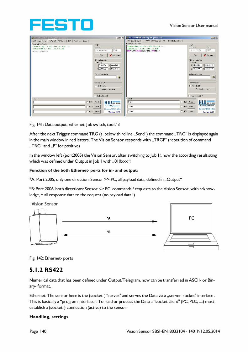
Page 140 Vision Sensor SBSI-EN, 8033104 - 1401N12.05.2014
Vision Sensor User manual
Fig. 141: Data output, Ethernet, Job switch, tool / 3
After the next Trigger command TRG (s. below third line „Send“) the command „TRG“ is displayed again
in the main window in red letters. The Vision Sensor responds with „TRGP“ (repetition of command
„TRG“ and „P“ for positive)
In the window left (port2005) the Vision Sensor, after switching to Job 1!, now the according result sting
which was defined under Output in Job 1 with „010xxx“!
Function of the both Ethernet- ports for in- and output:
*A: Port 2005, only one direction: Sensor >> PC, all payload data, defined in „Output“
*B: Port 2006, both directions: Sensor <> PC, commands / requests to the Vision Sensor, with acknow-
ledge, + all response data to the request (no payload data !)
Fig. 142: Ethernet- ports
5.1.2 RS422
Numerical data that has been defined under Output/Telegram, now can be transferred in ASCII- or Bin-
ary- format.
Ethernet: The sensor here is the (socket-)“server" and serves the Data via a „server-socket" interface .
This is basically a “program interface”. To read or process the Data a “socket client" (PC, PLC, ....) must
establish a (socket-) connection (active) to the sensor.
Handling, settings
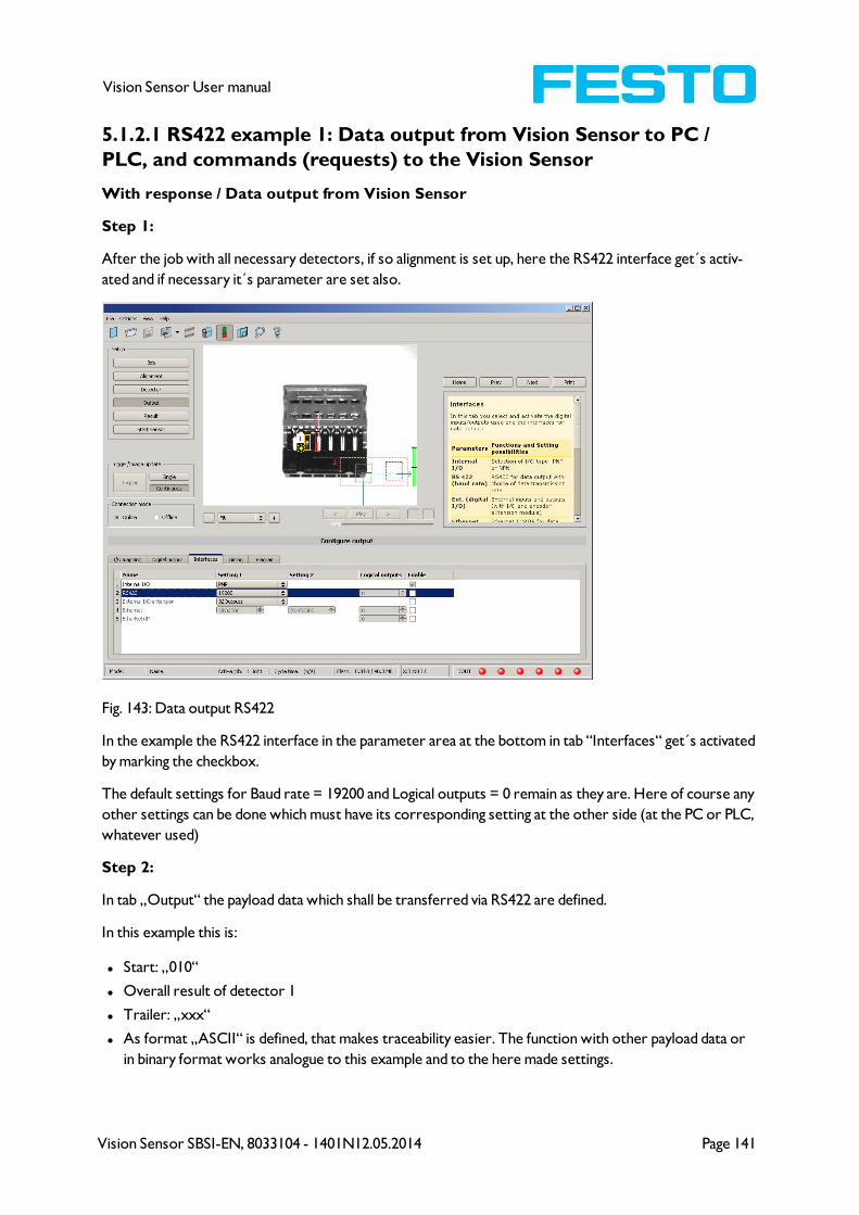
Vision Sensor SBSI-EN, 8033104 - 1401N12.05.2014 Page 141
Vision Sensor User manual
5.1.2.1 RS422 example 1: Data output from Vision Sensor to PC /
PLC, and commands (requests) to the Vision Sensor
With response / Data output from Vision Sensor
Step 1:
After the job with all necessary detectors, if so alignment is set up, here the RS422 interface get´s activ-
ated and if necessary it´s parameter are set also.
Fig. 143: Data output RS422
In the example the RS422 interface in the parameter area at the bottom in tab “Interfaces“ get´s activated
by marking the checkbox.
The default settings for Baud rate = 19200 and Logical outputs = 0 remain as they are. Here of course any
other settings can be done which must have its corresponding setting at the other side (at the PC or PLC,
whatever used)
Step 2:
In tab „Output“ the payload data which shall be transferred via RS422 are defined.
In this example this is:
l Start: „010“
l Overall result of detector 1
l Trailer: „xxx“
l As format „ASCII“ is defined, that makes traceability easier. The function with other payload data or
in binary format works analogue to this example and to the here made settings.

Page 142 Vision Sensor SBSI-EN, 8033104 - 1401N12.05.2014
Vision Sensor User manual
Fig. 144: Data output RS422, configuration of output data
Step 3:
The Vision Sensornow needs to be started form the PC application with „Start sensor“. (Later in
autonomous operation the Vision Sensor directly starts after power on, and sends data, if configured this
way).
In the example Trigger mode is continuous, that means evaluation is done continuously and data is sent
continuously too. All this data is visible in the main window of Hercules.
Fig. 145: Start sensor
Step 4:
After start of Serial- tool Hercules, tab „Serial“ must be selected to communicate via RS422 with the
socket server Vision Sensor.

Vision Sensor SBSI-EN, 8033104 - 1401N12.05.2014 Page 143
Vision Sensor User manual
Fig. 146: Data output, RS422 tool / 1
Now the corresponding settings for baud rate like in Vision Sensor must be done. Also the correct serial
port COMx must be set up her to receive data.
The baud rate you see in tab Output/Interfaces. The number of the serial COM port (COM x of the PC)
you find out in Windows at: Start/Control Panel/Performance and Maintenance/System/Hardware/Device
Manager, at Universal Serial Bus Controllers. (Here COM5).
The rest of the settings at the right are the default values of Hercules. „DTR“ and „RTS“ must be activ-
ated. With a click to the button „Connect“ the connection to the Vision Sensor is established and shown
in the main window in green letters.

Page 144 Vision Sensor SBSI-EN, 8033104 - 1401N12.05.2014
Vision Sensor User manual
Fig. 147: Data output, RS422 COMx
Step 5:
With a click to button „Send“ the command „TRG“ is sent to the Vision Sensor. It responds with „TRG“,
followed by „P“ for positive and the payload data „010Pxxx“.

Vision Sensor SBSI-EN, 8033104 - 1401N12.05.2014 Page 145
Vision Sensor User manual
Fig. 148: Data output, RS422, tool / 2
Step 6:
In the following example the command „SST041000“ (SetShutterTemporary, 04 = number of letters of
shutter value, 1000 = shutter value in microseconds) is sent and the Vision Sensor responds with SSTP
(SetShutterTemporary, P = positive). All available telegrams you find in chap. Serial Communication ASCII
ff. and are used in analogue way.
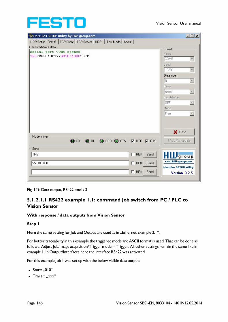
Page 146 Vision Sensor SBSI-EN, 8033104 - 1401N12.05.2014
Vision Sensor User manual
Fig. 149: Data output, RS422, tool / 3
5.1.2.1.1 RS422 example 1.1: command Job switch from PC / PLC to
Vision Sensor
With response / data outputs from Vision Sensor
Step 1
Here the same setting for Job and Output are used as in „Ethernet Example 2.1“.
For better traceability in this example the triggered mode and ASCII format is used. That can be done as
follows: Adjust Job/Image acquisition/Trigger mode = Trigger. All other settings remain the same like in
example 1. In Output/Interfaces here the interface RS422 was activated.
For this example Job 1 was set up with the below visible data output:
l Start: „010“
l Trailer: „xxx“

Vision Sensor SBSI-EN, 8033104 - 1401N12.05.2014 Page 147
Vision Sensor User manual
Fig. 150: Data output, RS422, Job switch, Job 1
Job2 was set up with detector 1 and data output:
l Start: „020“
l Overall result of detector 1
l Trailer: „yyy“
Fig. 151: Data output, RS422, Job switch, Job 2
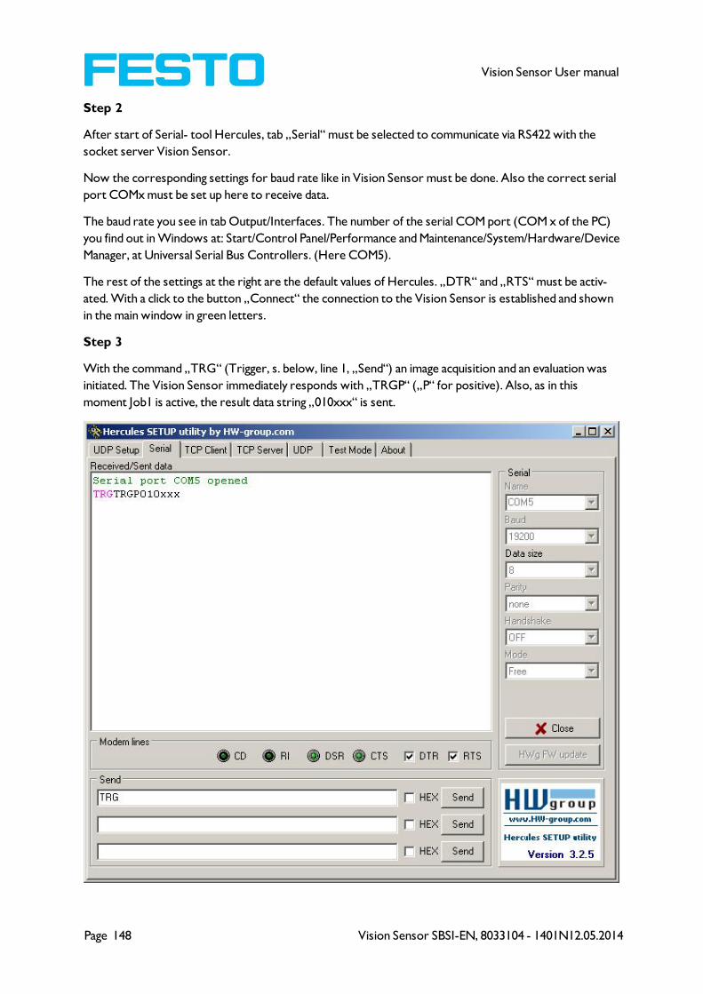
Page 148 Vision Sensor SBSI-EN, 8033104 - 1401N12.05.2014
Vision Sensor User manual
Step 2
After start of Serial- tool Hercules, tab „Serial“ must be selected to communicate via RS422 with the
socket server Vision Sensor.
Now the corresponding settings for baud rate like in Vision Sensor must be done. Also the correct serial
port COMx must be set up here to receive data.
The baud rate you see in tab Output/Interfaces. The number of the serial COM port (COM x of the PC)
you find out in Windows at: Start/Control Panel/Performance and Maintenance/System/Hardware/Device
Manager, at Universal Serial Bus Controllers. (Here COM5).
The rest of the settings at the right are the default values of Hercules. „DTR“ and „RTS“ must be activ-
ated. With a click to the button „Connect“ the connection to the Vision Sensor is established and shown
in the main window in green letters.
Step 3
With the command „TRG“ (Trigger, s. below, line 1, „Send“) an image acquisition and an evaluation was
initiated. The Vision Sensor immediately responds with „TRGP“ („P“ for positive). Also, as in this
moment Job1 is active, the result data string „010xxx“ is sent.
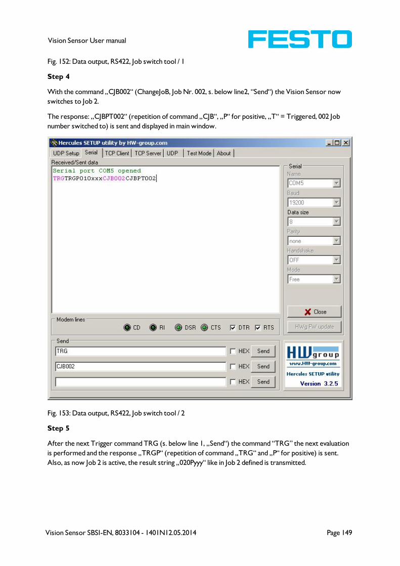
Vision Sensor SBSI-EN, 8033104 - 1401N12.05.2014 Page 149
Vision Sensor User manual
Fig. 152: Data output, RS422, Job switch tool / 1
Step 4
With the command „CJB002“ (ChangeJoB, Job Nr. 002, s. below line2, “Send“) the Vision Sensor now
switches to Job 2.
The response: „CJBPT002“ (repetition of command „CJB“, „P“ for positive, „T“ = Triggered, 002 Job
number switched to) is sent and displayed in main window.
Fig. 153: Data output, RS422, Job switch tool / 2
Step 5
After the next Trigger command TRG (s. below line 1, „Send“) the command “TRG” the next evaluation
is performed and the response „TRGP“ (repetition of command „TRG“ and „P“ for positive) is sent.
Also, as now Job 2 is active, the result string „020Pyyy“ like in Job 2 defined is transmitted.
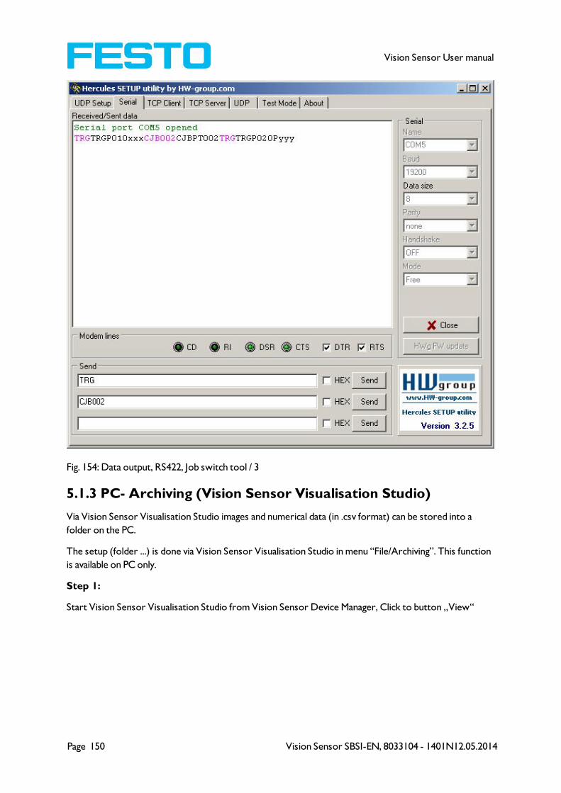
Page 150 Vision Sensor SBSI-EN, 8033104 - 1401N12.05.2014
Vision Sensor User manual
Fig. 154: Data output, RS422, Job switch tool / 3
5.1.3 PC- Archiving (Vision Sensor Visualisation Studio)
Via Vision Sensor Visualisation Studio images and numerical data (in .csv format) can be stored into a
folder on the PC.
The setup (folder ...) is done via Vision Sensor Visualisation Studio in menu “File/Archiving”. This function
is available on PC only.
Step 1:
Start Vision Sensor Visualisation Studio from Vision Sensor Device Manager, Click to button „View“
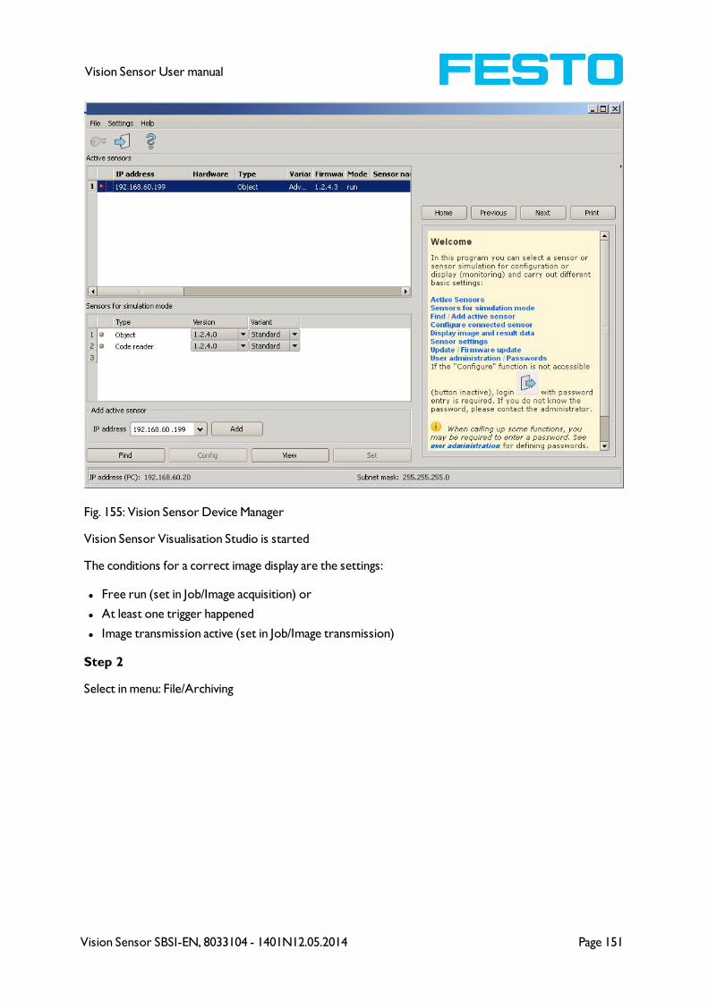
Vision Sensor SBSI-EN, 8033104 - 1401N12.05.2014 Page 151
Vision Sensor User manual
Fig. 155: Vision Sensor Device Manager
Vision Sensor Visualisation Studio is started
The conditions for a correct image display are the settings:
l Free run (set in Job/Image acquisition) or
l At least one trigger happened
l Image transmission active (set in Job/Image transmission)
Step 2
Select in menu: File/Archiving
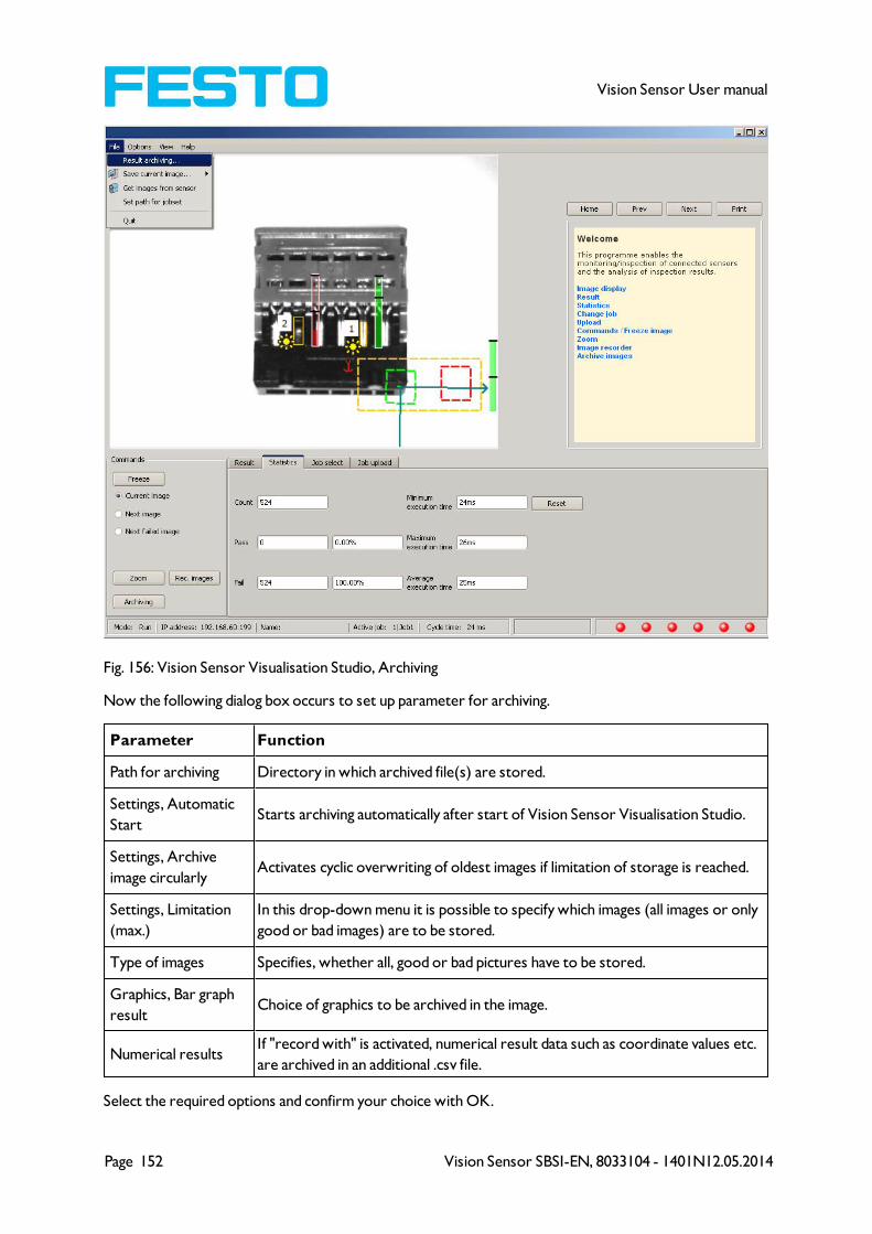
Page 152 Vision Sensor SBSI-EN, 8033104 - 1401N12.05.2014
Vision Sensor User manual
Fig. 156: Vision Sensor Visualisation Studio, Archiving
Now the following dialog box occurs to set up parameter for archiving.
Parameter Function
Path for archiving Directory in which archived file(s) are stored.
Settings, Automatic
StartStarts archiving automatically after start of Vision Sensor Visualisation Studio.
Settings, Archive
image circularlyActivates cyclic overwriting of oldest images if limitation of storage is reached.
Settings, Limitation
(max.)
In this drop-down menu it is possible to specify which images (all images or only
good or bad images) are to be stored.
Type of images Specifies, whether all, good or bad pictures have to be stored.
Graphics, Bar graph
resultChoice of graphics to be archived in the image.
Numerical resultsIf "record with" is activated, numerical result data such as coordinate values etc.
are archived in an additional .csv file.
Select the required options and confirm your choice with OK.
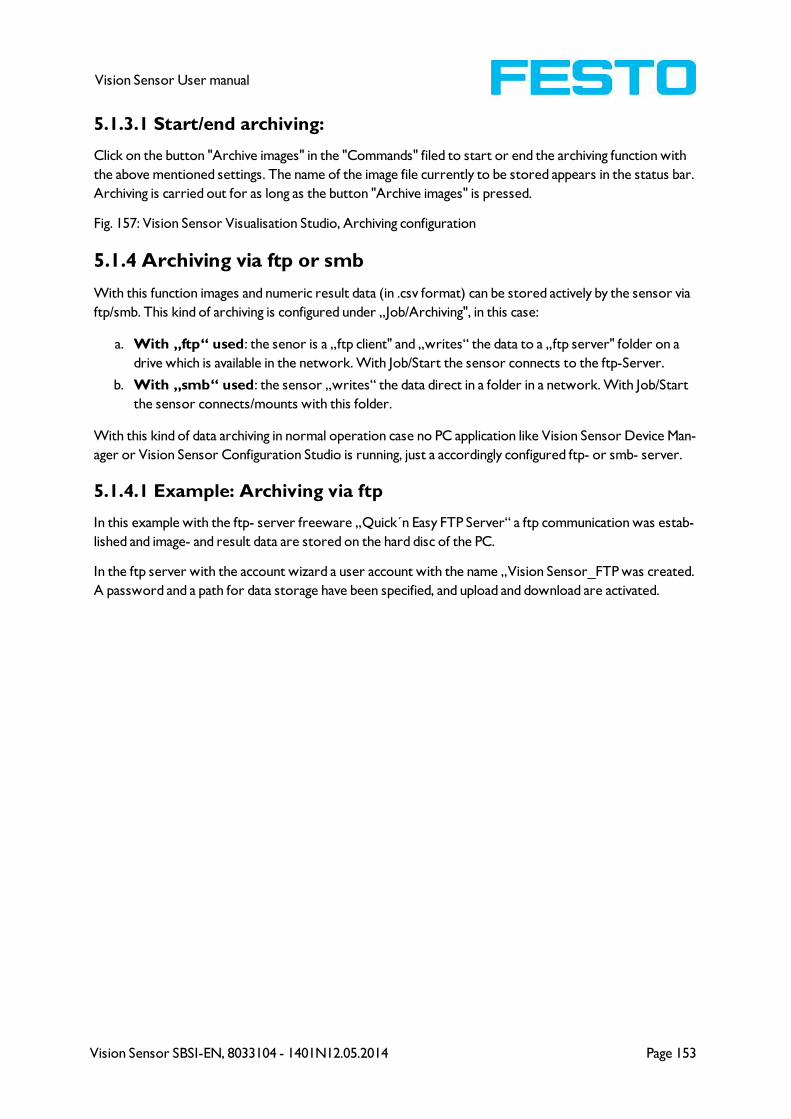
Vision Sensor SBSI-EN, 8033104 - 1401N12.05.2014 Page 153
Vision Sensor User manual
5.1.3.1 Start/end archiving:
Click on the button "Archive images" in the "Commands" filed to start or end the archiving function with
the above mentioned settings. The name of the image file currently to be stored appears in the status bar.
Archiving is carried out for as long as the button "Archive images" is pressed.
Fig. 157: Vision Sensor Visualisation Studio, Archiving configuration
5.1.4 Archiving via ftp or smb
With this function images and numeric result data (in .csv format) can be stored actively by the sensor via
ftp/smb. This kind of archiving is configured under „Job/Archiving", in this case:
a. With „ftp“ used: the senor is a „ftp client" and „writes“ the data to a „ftp server" folder on a
drive which is available in the network. With Job/Start the sensor connects to the ftp-Server.
b. With „smb“ used: the sensor „writes“ the data direct in a folder in a network. With Job/Start
the sensor connects/mounts with this folder.
With this kind of data archiving in normal operation case no PC application like Vision Sensor Device Man-
ager or Vision Sensor Configuration Studio is running, just a accordingly configured ftp- or smb- server.
5.1.4.1 Example: Archiving via ftp
In this example with the ftp- server freeware „Quick´n Easy FTP Server“ a ftp communication was estab-
lished and image- and result data are stored on the hard disc of the PC.
In the ftp server with the account wizard a user account with the name „Vision Sensor_FTP was created.
A password and a path for data storage have been specified, and upload and download are activated.
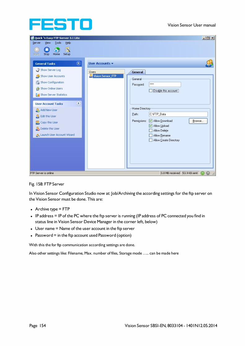
Page 154 Vision Sensor SBSI-EN, 8033104 - 1401N12.05.2014
Vision Sensor User manual
Fig. 158: FTP Server
In Vision Sensor Configuration Studio now at: Job/Archiving the according settings for the ftp server on
the Vision Sensor must be done. This are:
l Archive type = FTP
l IP address = IP of the PC where the ftp server is running (IP address of PC connected you find in
status line in Vision Sensor Device Manager in the corner left, below)
l User name = Name of the user account in the ftp server
l Password = in the ftp account used Password (option)
With this the for ftp communication according settings are done.
Also other settings like: Filename, Max. number of files, Storage mode ….. can be made here
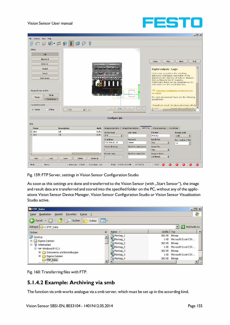
Vision Sensor SBSI-EN, 8033104 - 1401N12.05.2014 Page 155
Vision Sensor User manual
Fig. 159: FTP Server, settings in Vision Sensor Configuration Studio
As soon as this settings are done and transferred to the Vision Sensor (with „Start Sensor“), the image
and result data are transferred and stored into the specified folder on the PC, without any of the applic-
ations Vision Sensor Device Manager, Vision Sensor Configuration Studio or Vision Sensor Visualisation
Studio active.
Fig. 160: Transferring files with FTP.
5.1.4.2 Example: Archiving via smb
The function via smb works analogue via a smb server, which must be set up in the according kind.
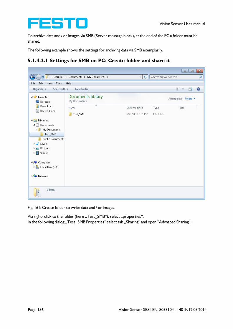
Page 156 Vision Sensor SBSI-EN, 8033104 - 1401N12.05.2014
Vision Sensor User manual
To archive data and / or images via SMB (Server message block), at the end of the PC a folder must be
shared.
The following example shows the settings for archiving data via SMB exemplarily.
5.1.4.2.1 Settings for SMB on PC: Create folder and share it
Fig. 161: Create folder to write data and / or images.
Via right- click to the folder (here „Test_SMB“), select „properties“.
In the following dialog „Test_SMB Properties“ select tab „Sharing” and open “Advnaced Sharing”.
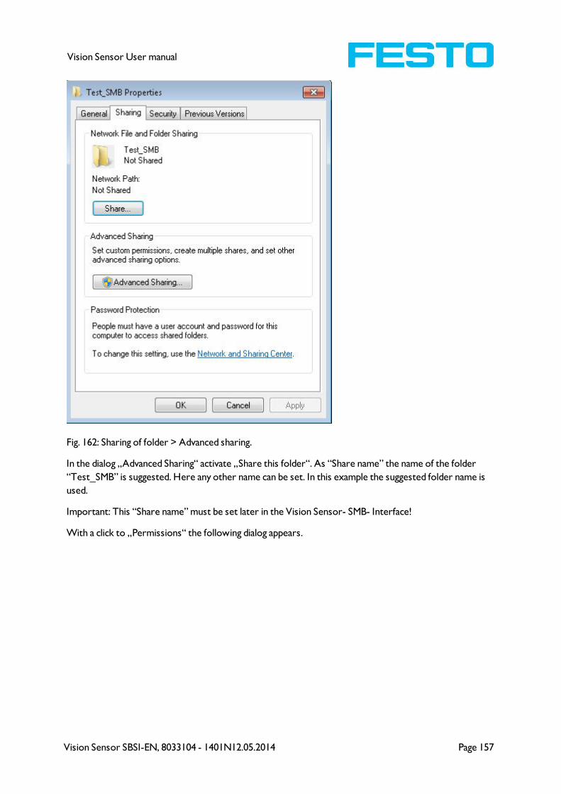
Vision Sensor SBSI-EN, 8033104 - 1401N12.05.2014 Page 157
Vision Sensor User manual
Fig. 162: Sharing of folder > Advanced sharing.
In the dialog „Advanced Sharing“ activate „Share this folder“. As “Share name” the name of the folder
“Test_SMB” is suggested. Here any other name can be set. In this example the suggested folder name is
used.
Important: This “Share name” must be set later in the Vision Sensor- SMB- Interface!
With a click to „Permissions“ the following dialog appears.

Page 158 Vision Sensor SBSI-EN, 8033104 - 1401N12.05.2014
Vision Sensor User manual
Fig. 163: Set Share name.
In the window „Permissions for Test_SMB”,
either
Select user group “Everyone”. With this choice everybody in the network has free access to the folder
without any further login, and in the Vision Sensor- SMB – interface the fields: “User name” and “Pass-
word” remain empty.
or:
select a user (here „fsc“), (for which user name and password is known). User name and password are
necessary later to be set in the Vision Sensor- SMB- Interface.
Activate „Full control“,
and close the dialog with „Apply“ and „OK“.
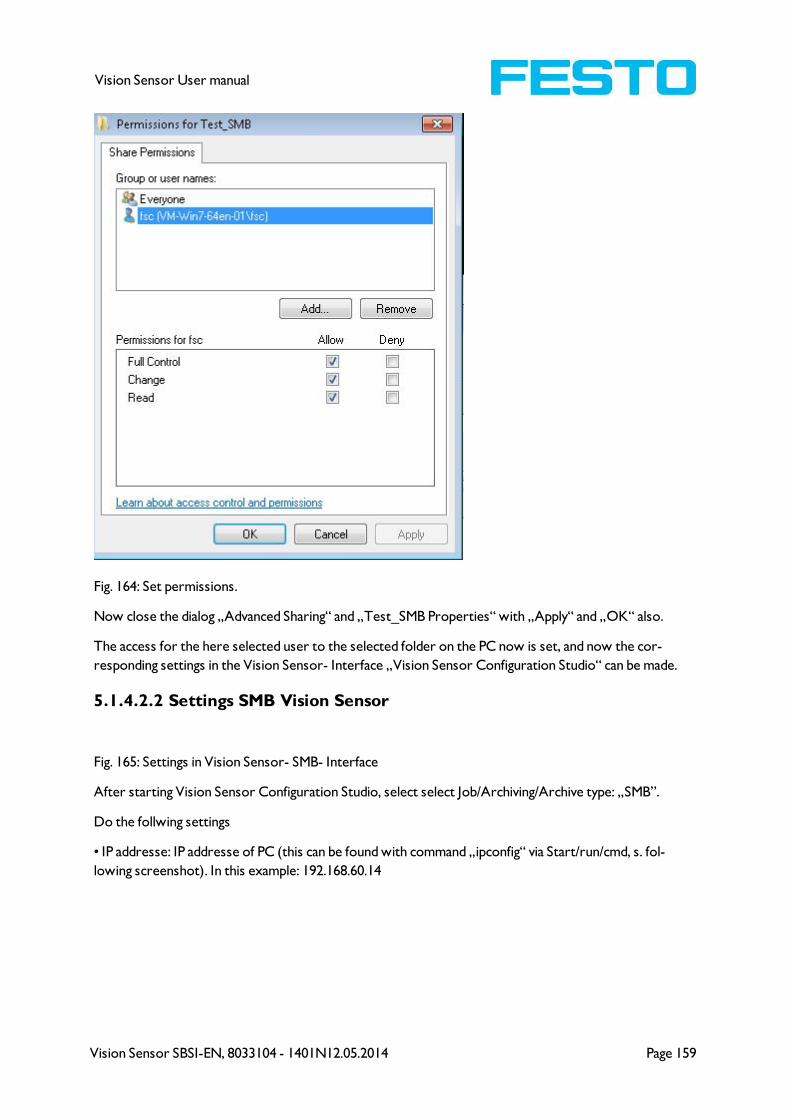
Vision Sensor SBSI-EN, 8033104 - 1401N12.05.2014 Page 159
Vision Sensor User manual
Fig. 164: Set permissions.
Now close the dialog „Advanced Sharing“ and „Test_SMB Properties“ with „Apply“ and „OK“ also.
The access for the here selected user to the selected folder on the PC now is set, and now the cor-
responding settings in the Vision Sensor- Interface „Vision Sensor Configuration Studio“ can be made.
5.1.4.2.2 Settings SMB Vision Sensor
Fig. 165: Settings in Vision Sensor- SMB- Interface
After starting Vision Sensor Configuration Studio, select select Job/Archiving/Archive type: „SMB”.
Do the follwing settings
• IP addresse: IP addresse of PC (this can be found with command „ipconfig“ via Start/run/cmd, s. fol-
lowing screenshot). In this example: 192.168.60.14
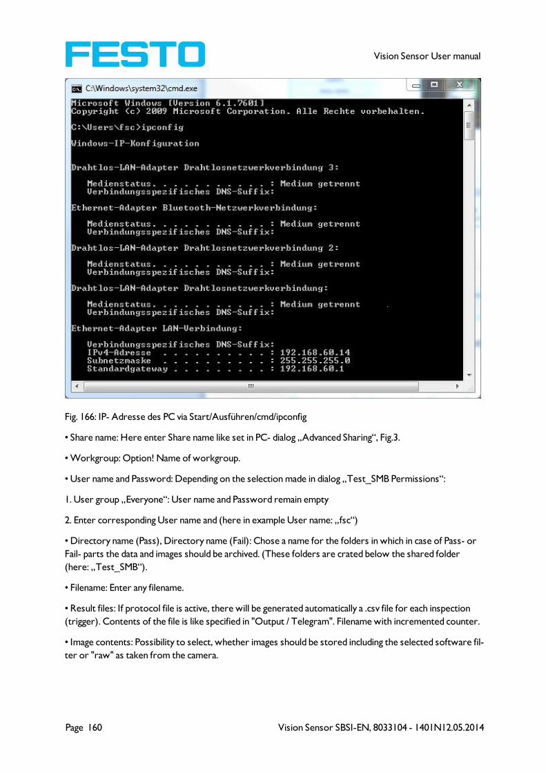
Page 160 Vision Sensor SBSI-EN, 8033104 - 1401N12.05.2014
Vision Sensor User manual
Fig. 166: IP- Adresse des PC via Start/Ausführen/cmd/ipconfig
• Share name: Here enter Share name like set in PC- dialog „Advanced Sharing“, Fig.3.
• Workgroup: Option! Name of workgroup.
• User name and Password: Depending on the selection made in dialog „Test_SMB Permissions“:
1. User group „Everyone“: User name and Password remain empty
2. Enter corresponding User name and (here in example User name: „fsc“)
• Directory name (Pass), Directory name (Fail): Chose a name for the folders in which in case of Pass- or
Fail- parts the data and images should be archived. (These folders are crated below the shared folder
(here: „Test_SMB“).
• Filename: Enter any filename.
• Result files: If protocol file is active, there will be generated automatically a .csv file for each inspection
(trigger). Contents of the file is like specified in "Output / Telegram". Filename with incremented counter.
• Image contents: Possibility to select, whether images should be stored including the selected software fil-
ter or "raw" as taken from the camera.
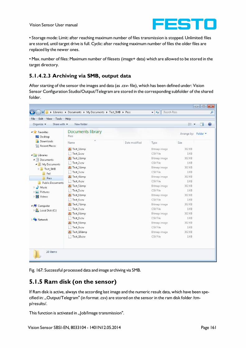
Vision Sensor SBSI-EN, 8033104 - 1401N12.05.2014 Page 161
Vision Sensor User manual
• Storage mode: Limit: after reaching maximum number of files transmission is stopped. Unlimited: files
are stored, until target drive is full. Cyclic: after reaching maximum number of files the older files are
replaced by the newer ones.
• Max. number of files: Maximum number of filesets (image+ data) which are allowed to be stored in the
target directory.
5.1.4.2.3 Archiving via SMB, output data
After starting of the sensor the images and data (as .csv- file), which has been defined under: Vision
Sensor Configuration Studio/Output/Telegram are stored in the corresponding subfolder of the shared
folder.
Fig. 167: Successful processed data and image archiving via SMB.
5.1.5 Ram disk (on the sensor)
If Ram disk is active, always the according last image and the numeric result data, which have been spe-
cified in: „Output/Telegram" (in format .csv) are stored on the sensor in the ram disk folder /tm-
p/results/.
This function is activated in „Job/Image transmission".
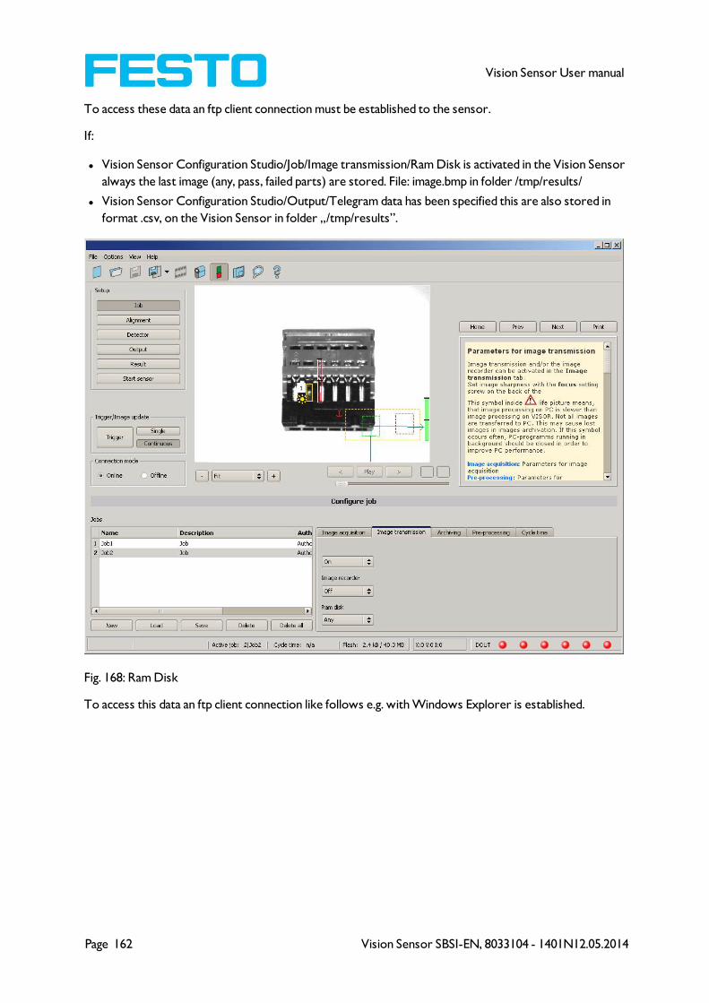
Page 162 Vision Sensor SBSI-EN, 8033104 - 1401N12.05.2014
Vision Sensor User manual
To access these data an ftp client connection must be established to the sensor.
If:
l Vision Sensor Configuration Studio/Job/Image transmission/Ram Disk is activated in the Vision Sensor
always the last image (any, pass, failed parts) are stored. File: image.bmp in folder /tmp/results/
l Vision Sensor Configuration Studio/Output/Telegram data has been specified this are also stored in
format .csv, on the Vision Sensor in folder „/tmp/results”.
Fig. 168: Ram Disk
To access this data an ftp client connection like follows e.g. with Windows Explorer is established.
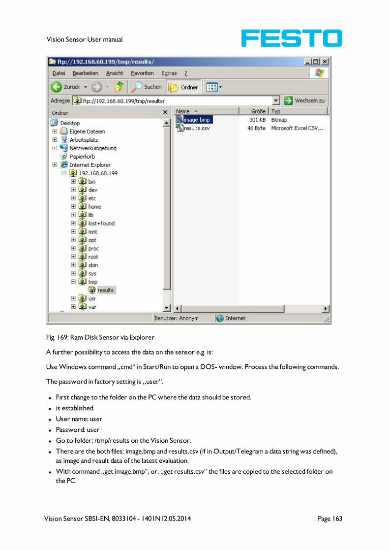
Vision Sensor SBSI-EN, 8033104 - 1401N12.05.2014 Page 163
Vision Sensor User manual
Fig. 169: Ram Disk Sensor via Explorer
A further possibility to access the data on the sensor e.g. is:
Use Windows command „cmd“ in Start/Run to open a DOS- window. Process the following commands.
The password in factory setting is „user“.
l First change to the folder on the PC where the data should be stored.
l is established.
l User name: user
l Password: user
l Go to folder: /tmp/results on the Vision Sensor.
l There are the both files: image.bmp and results.csv (if in Output/Telegram a data string was defined),
as image and result data of the latest evaluation.
l With command „get image.bmp“, or. „get results.csv“ the files are copied to the selected folder on
the PC
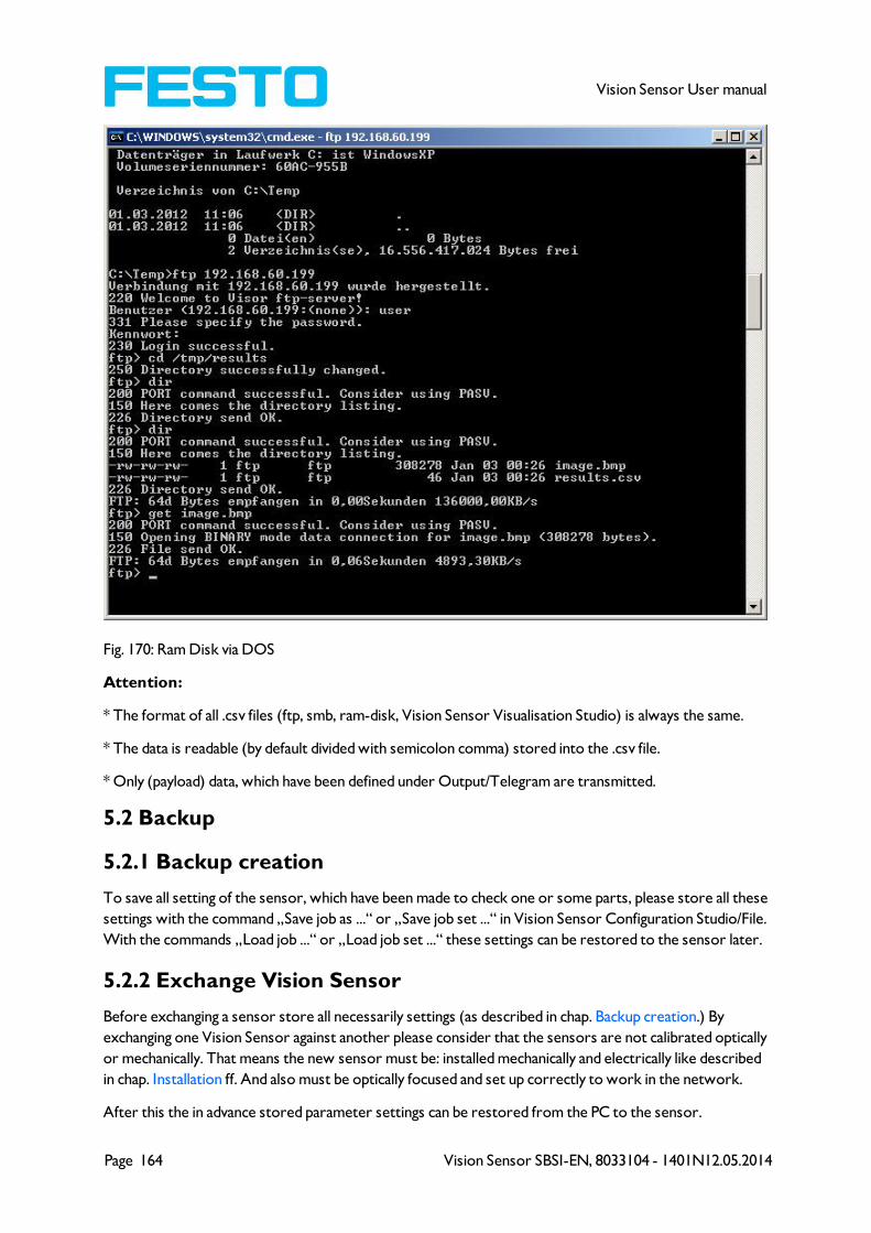
Page 164 Vision Sensor SBSI-EN, 8033104 - 1401N12.05.2014
Vision Sensor User manual
Fig. 170: Ram Disk via DOS
Attention:
* The format of all .csv files (ftp, smb, ram-disk, Vision Sensor Visualisation Studio) is always the same.
* The data is readable (by default divided with semicolon comma) stored into the .csv file.
* Only (payload) data, which have been defined under Output/Telegram are transmitted.
5.2 Backup
5.2.1 Backup creation
To save all setting of the sensor, which have been made to check one or some parts, please store all these
settings with the command „Save job as ...“ or „Save job set ...“ in Vision Sensor Configuration Studio/File.
With the commands „Load job ...“ or „Load job set ...“ these settings can be restored to the sensor later.
5.2.2 Exchange Vision Sensor
Before exchanging a sensor store all necessarily settings (as described in chap. Backup creation.) By
exchanging one Vision Sensor against another please consider that the sensors are not calibrated optically
or mechanically. That means the new sensor must be: installed mechanically and electrically like described
in chap. Installation ff. And also must be optically focused and set up correctly to work in the network.
After this the in advance stored parameter settings can be restored from the PC to the sensor.

Vision Sensor SBSI-EN, 8033104 - 1401N12.05.2014 Page 165
Vision Sensor User manual
5.3 Job switch
5.3.1 Job switch via digital inputs
To switch between several jobs, which are already stored on the sensor, via digital inputs the following
options are available:
S. also chap. ff., timing diagrams and comments
5.3.1.1 Job 1 or Job 2
To switch between Job1 and Job2 any input can be defined in Vision Sensor Configuration Stu-
dio/Output/I/O mapping with the function „Job 1 or 2“. After the according logical level is connected to
this input Job 1 or Job 2 is processed Low = Job1, High = Job 2). S. also chap. I/O mapping (Page 94) / Func-
tion of inputs ff.
5.3.1.2 Job 1… 31 via binary bit pattern
To switch between up to 31 jobs by binary input pattern via the up to 5 digital inputs, all needed inputs in
Vision Sensor Configuration Studio/Output/I/O mapping are set to the according function “Job switch
(Bitx)”.
The in the following graphics shown binary input pattern then switch directly to the according job num-
ber. S. also chap. I/O mapping (Page 94) / Function of inputs ff.
Attention:
l Job switch starts / happens immediately after the input pattern has changed.
l The display of the active job changes with the first following trigger.
l The mapping of the I/O´s is not fixed. It´s depending on the settings in Vision Sensor Configuration
Studio/Output/I/O mapping.
l The change of the logical level of all related inputs must happen at the same time.
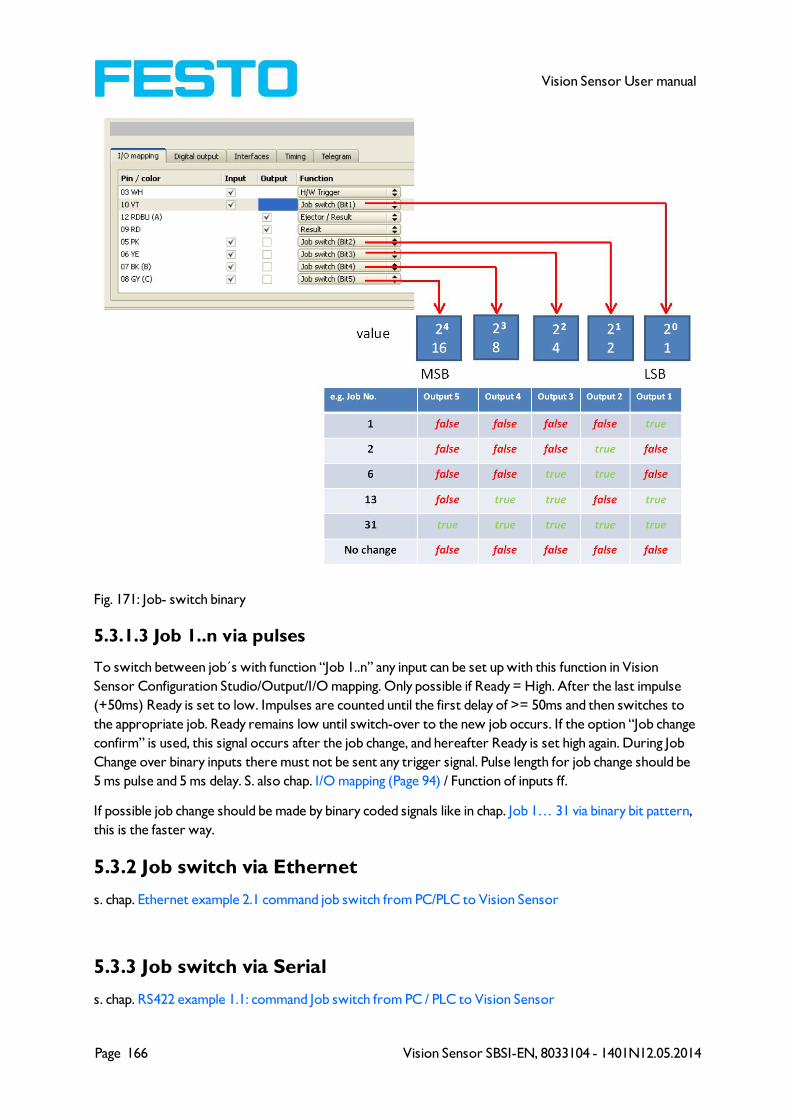
Page 166 Vision Sensor SBSI-EN, 8033104 - 1401N12.05.2014
Vision Sensor User manual
Fig. 171: Job- switch binary
5.3.1.3 Job 1..n via pulses
To switch between job´s with function “Job 1..n” any input can be set up with this function in Vision
Sensor Configuration Studio/Output/I/O mapping. Only possible if Ready = High. After the last impulse
(+50ms) Ready is set to low. Impulses are counted until the first delay of >= 50ms and then switches to
the appropriate job. Ready remains low until switch-over to the new job occurs. If the option “Job change
confirm” is used, this signal occurs after the job change, and hereafter Ready is set high again. During Job
Change over binary inputs there must not be sent any trigger signal. Pulse length for job change should be
5 ms pulse and 5 ms delay. S. also chap. I/O mapping (Page 94) / Function of inputs ff.
If possible job change should be made by binary coded signals like in chap. Job 1… 31 via binary bit pattern,
this is the faster way.
5.3.2 Job switch via Ethernet
s. chap. Ethernet example 2.1 command job switch from PC/PLC to Vision Sensor
5.3.3 Job switch via Serial
s. chap. RS422 example 1.1: command Job switch from PC / PLC to Vision Sensor
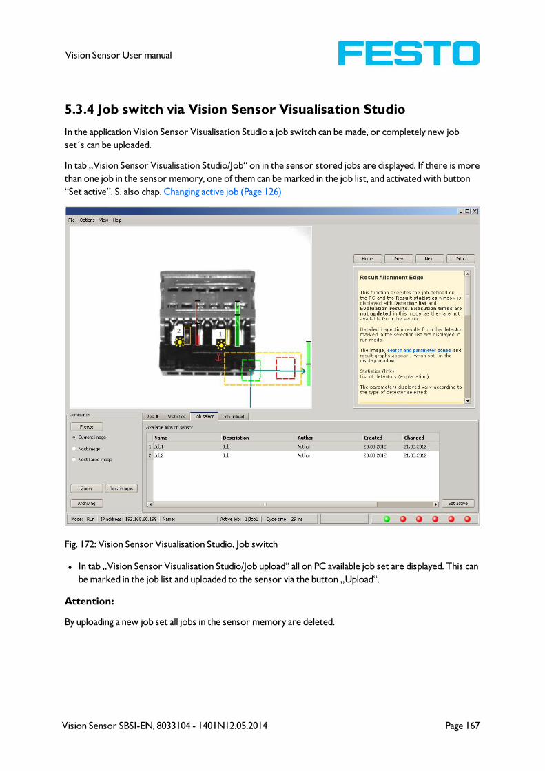
Vision Sensor SBSI-EN, 8033104 - 1401N12.05.2014 Page 167
Vision Sensor User manual
5.3.4 Job switch via Vision Sensor Visualisation Studio
In the application Vision Sensor Visualisation Studio a job switch can be made, or completely new job
set´s can be uploaded.
In tab „Vision Sensor Visualisation Studio/Job“ on in the sensor stored jobs are displayed. If there is more
than one job in the sensor memory, one of them can be marked in the job list, and activated with button
“Set active”. S. also chap. Changing active job (Page 126)
Fig. 172: Vision Sensor Visualisation Studio, Job switch
l In tab „Vision Sensor Visualisation Studio/Job upload“ all on PC available job set are displayed. This can
be marked in the job list and uploaded to the sensor via the button „Upload“.
Attention:
By uploading a new job set all jobs in the sensor memory are deleted.

Page 168 Vision Sensor SBSI-EN, 8033104 - 1401N12.05.2014
Vision Sensor User manual
Fig. 173: Vision Sensor Visualisation Studio, Job upload
5.4 Network connection
5.4.1 Installation of Vision Sensor into a network / gateway
In Vision Sensor Device Manager/Active sensors, all Vision sensors, which are installed in the same net-
work segment as the PC which runs Vision Sensor Device Manager are displayed as list. To update this
list press the button „Find“, to see sensors which e.g. have been powered after Vision Sensor Device
Manager was started.
For sensors, which are installed in the network, but are located in a different network segment via a gate-
way, please enter their IP address in the field „Add active sensor“ and press button „Add“. „
The according sensor now appears in the list „Active sensors“ and can be accessed now.
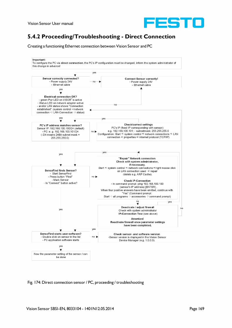
Vision Sensor SBSI-EN, 8033104 - 1401N12.05.2014 Page 169
Vision Sensor User manual
5.4.2 Proceeding/Troubleshooting - Direct Connection
Creating a functioning Ethernet connection between Vision Sensor and PC
Fig. 174: Direct connection sensor / PC, proceeding / troubleshooting
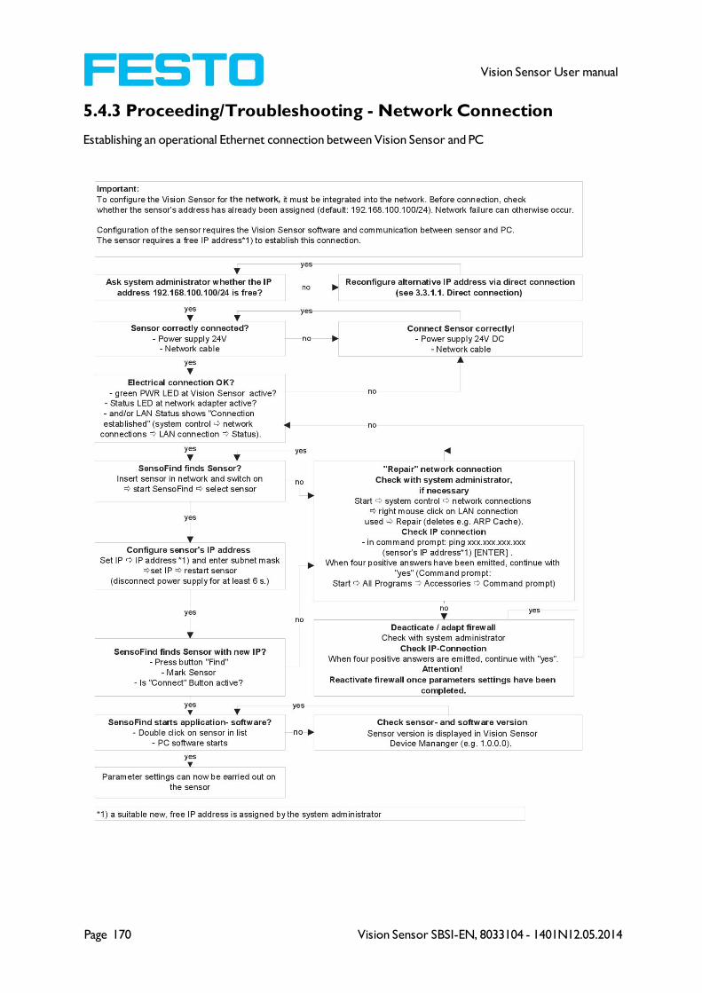
Page 170 Vision Sensor SBSI-EN, 8033104 - 1401N12.05.2014
Vision Sensor User manual
5.4.3 Proceeding/Troubleshooting - Network Connection
Establishing an operational Ethernet connection between Vision Sensor and PC
Vision Sensor SBSI-EN, 8033104 - 1401N12.05.2014 Page 171
Vision Sensor User manual
Fig. 175: Connection via network sensor / PC, proceeding / troubleshooting
5.4.4 Used Ethernet- Ports
If the Vision Sensor should be installed into a network, the following ports must be enabled, if so by the
network administrator. This is necessary only in case that this specific ports have been locked e.g. in a
company network by a firewall installed on a PC.
To communicate between a PC fur configuration and the Vision Sensor the following ports are used:
* Port 2000, TCP
* Port 2001, UDP Broadcast (to find sensors via Vision Sensor Device Manager)
* Port 2002, TCP
* Port 2003, TCP
* Port 2004, TCP
To communicate between PLC (PLC- PC also) and the Vision Sensor the following ports are used.
* Port 2005, TCP (Implicit results, that means, user configured result data)
* Port 2006, TCP (Explicit requests, e.g. trigger or job switch)
If the ports 2005 or 2006 are changed in Vision Sensor Configuration Studio, the according ports also
must be enabled in the firewall by the administrator.
If the interface EtherNet/IP is used the following two ports must be enabled too.
* Port 2222, UDP (EtherNet/IP)
* Port 44818, TCP (EtherNet/IP)
5.4.5 Access to the Vision Sensor via network
Exemplary values for IP etc.
Access to Vision Sensor 1 from PC 1, if in same subnet.
l Via Vision Sensor Device Manager (/find)
Access to Vision Sensor 2 from PC1, if in different subnet.
Only if:
l Gateway is set correct in sensor 2 (here to 192.168.30.1) - and
l in Vision Sensor Device Manager via Add- IP- the sensor IP of sensor 2 is set correct
> now the Vision Sensor 2 appears in the list „Active Sensors“ in Vision Sensor Device Manager
!

Page 172 Vision Sensor SBSI-EN, 8033104 - 1401N12.05.2014
Vision Sensor User manual
Fig. 176: Access to Vision Sensor via network, same or different subnet

Vision Sensor SBSI-EN, 8033104 - 1401N12.05.2014 Page 173
Vision Sensor User manual
5.4.6 Access to the Vision Sensor via Internet / World Wide Web
Exemplary values für IP etc.
Access from PC 1 (company network 1), via Word Wide Web, into company network 2 to
Vision Sensor 1
l Add the IP- WAN of router 2 (company network 2) in PC1 (company network 1) in Vision Sensor
Device Manager under „Add active sensor“ (here in example: 62.75.148.101)
In router 2 the ports which should be used by the sensor must be defined. (s. also chap. Used Ethernet-
Ports (Page 171))

Page 174 Vision Sensor SBSI-EN, 8033104 - 1401N12.05.2014
Vision Sensor User manual
Fig. 177: Access to Vision Sensor via Internet / World Wide Web
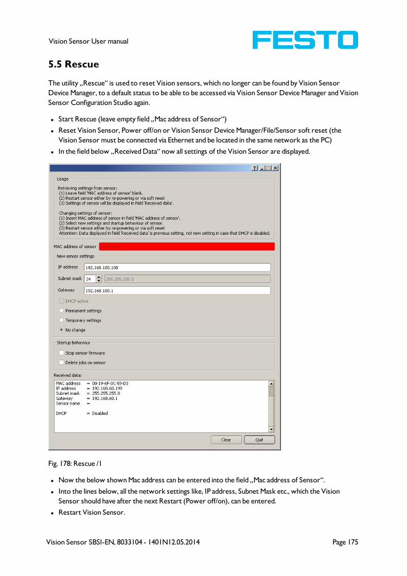
Vision Sensor SBSI-EN, 8033104 - 1401N12.05.2014 Page 175
Vision Sensor User manual
5.5 Rescue
The utility „Rescue“ is used to reset Vision sensors, which no longer can be found by Vision Sensor
Device Manager, to a default status to be able to be accessed via Vision Sensor Device Manager and Vision
Sensor Configuration Studio again.
l Start Rescue (leave empty field „Mac address of Sensor“)
l Reset Vision Sensor, Power off/on or Vision Sensor Device Manager/File/Sensor soft reset (the
Vision Sensor must be connected via Ethernet and be located in the same network as the PC)
l In the field below „Received Data“ now all settings of the Vision Sensor are displayed.
Fig. 178: Rescue /1
l Now the below shown Mac address can be entered into the field „Mac address of Sensor“.
l Into the lines below, all the network settings like, IP address, Subnet Mask etc., which the Vision
Sensor should have after the next Restart (Power off/on), can be entered.
l Restart Vision Sensor.

Page 176 Vision Sensor SBSI-EN, 8033104 - 1401N12.05.2014
Vision Sensor User manual
Attention:
The after the next restart displayed data are the old ones as they are not refreshed by sensor restart.
Fig. 179: Rescue / 2
Vision Sensor SBSI-EN, 8033104 - 1401N12.05.2014 Page 177
Vision Sensor User manual
6 Image settings and accessories
6.1 Good images
To achieve good images follow these steps:
l Align the sensor to the desired field of view. Take care for stable mounting.
l For high contrast images adjust angles and illumination like described in chap. The most important
types of illumination are: Bright field, Dark field and Diffuse illumination..
l Adjust a sharp image with the focus screw at the backside of the sensor housing.
l Adjust the brightness of the image with the parameter “Shutter speed“ in Vision Sensor Con-
figuration Studio/Job/Image acquisition. (Do not use parameter "Gain“, not until you are not able to
achieve desired brightness via "Shutter speed“)
6.2 Environmental light, shrouding, IR- version
Mechanical shrouding
In most cases it´s much simpler and highly cost effective to protect the scene against disturbing light or
sun beams, which e.g. shine temporary at a certain time of day or season from windows or roof lights, by
mechanical shrouding like metal plates, than to create illumination conditions, e.g. by additional illumination
which is strong enough not to be disturbed in any situation.
Version with Infrared illumination
A further elegant way to get independent from the environmental light is to use the according Vision
Sensor version with Infrared illumination. Here the scene get´s illuminated with the built in powerful IR-
illumination. The receiver is equipped with the according filter. That means the sensor works in a narrow
range of this specific wavelength, and for that as far as possible with its own light only.
Another advantage of the infrared light is, that the light flashes are not visible and do not disturb any
human workers which are near the plant.
6.3 External illumination
For the Vision Sensor a large range of accessories is available, which also covers a big range of external illu-
minations, which can be used additionally or instead of the internal illumination.
The both types SBAL-C6-A- xxx and SBAL-C6-R- xxx can be connected directly to the sensor.
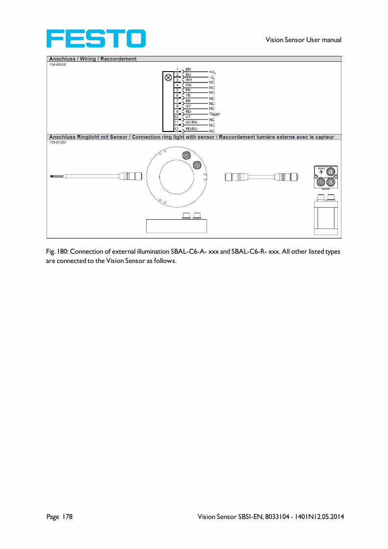
Page 178 Vision Sensor SBSI-EN, 8033104 - 1401N12.05.2014
Vision Sensor User manual
Fig. 180: Connection of external illumination SBAL-C6-A- xxx and SBAL-C6-R- xxx. All other listed types
are connected to the Vision Sensor as follows.

Vision Sensor SBSI-EN, 8033104 - 1401N12.05.2014 Page 179
Vision Sensor User manual
6.4 The most important types of illumination are: Bright field,
Dark field and Diffuse illumination.
6.4.1 Bright field illumination
Bright field internal / Bright field external
Fig. 181: Bright field illumination
With bright field lighting, the lighting, sensor and object are arranged so that the object’s surface reflects
the light directly into the sensor. The smooth surface of the object appears as a bright area and each
indentation, bump or defect, such as e.g. scratches, are a dark edge.
Attention: With bright field lighting, the angle of alignment between the lighting, object and sensor and the
object’s surface is critical as direct reflection by the object’s surface only works when the angle and sur-
face characteristics (shiny, mat, oily ….) are constant!
With Bright field / With Dark field
Fig. 182: Example Bright field illumination
By the direct reflection of the highly reflective (shiny) metal part, even before a white background, this is
possible to be distinguished and recognized with Bright field illumination! With Dark field illumination it´s
not possible to distinguish between shiny metal part and white background!

Page 180 Vision Sensor SBSI-EN, 8033104 - 1401N12.05.2014
Vision Sensor User manual
6.4.2 Dark field illumination
Dark field internal / Dark field external
Fig. 183: Dark field illumination
With dark field illumination, the lighting, sensor and object are arranged so that the smooth surface of the
object does not reflect the light directly into the sensor. Object edges (indentations and bumps) appear as
bright areas, smooth object surfaces however are dark. This type of illumination functions with wide
angle ranges and depends little on the object’s surface.
With Bright field / With Dark field
Fig. 184: Example, Dark field
Edges are clearly accentuated with Dark field illumination.
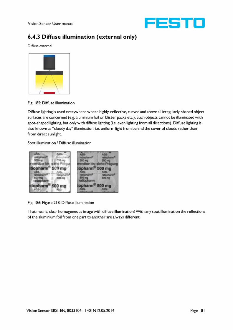
Vision Sensor SBSI-EN, 8033104 - 1401N12.05.2014 Page 181
Vision Sensor User manual
6.4.3 Diffuse illumination (external only)
Diffuse external
Fig. 185: Diffuse illumination
Diffuse lighting is used everywhere where highly-reflective, curved and above all irregularly-shaped object
surfaces are concerned (e.g. aluminium foil on blister packs etc.). Such objects cannot be illuminated with
spot-shaped lighting, but only with diffuse lighting (i.e. even lighting from all directions). Diffuse lighting is
also known as “cloudy day“ illumination, i.e. uniform light from behind the cover of clouds rather than
from direct sunlight.
Spot illumination / Diffuse illumination
Fig. 186: Figure 218. Diffuse illumination
That means; clear homogeneous image with diffuse illumination! With any spot illumination the reflections
of the aluminium foil from one part to another are always different.
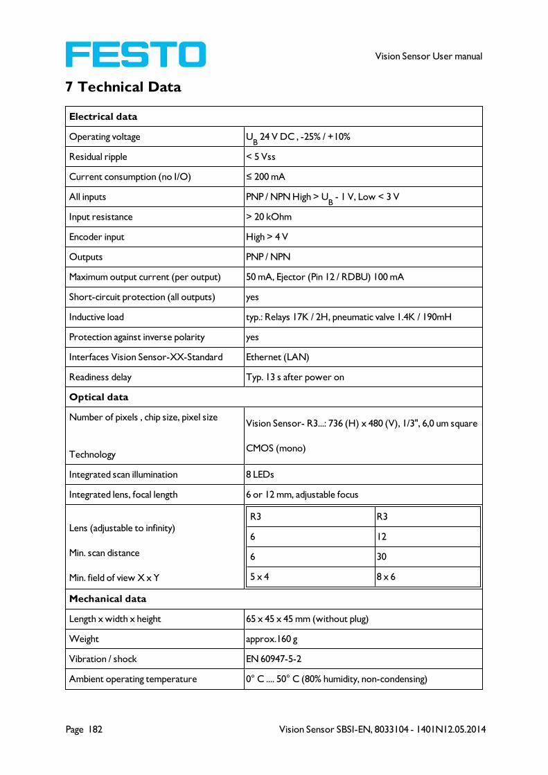
Page 182 Vision Sensor SBSI-EN, 8033104 - 1401N12.05.2014
Vision Sensor User manual
7 Technical Data
Electrical data
Operating voltage UB
24 V DC , -25% / +10%
Residual ripple < 5 Vss
Current consumption (no I/O) ≤ 200 mA
All inputs PNP / NPN High > UB
- 1 V, Low < 3 V
Input resistance > 20 kOhm
Encoder input High > 4 V
Outputs PNP / NPN
Maximum output current (per output) 50 mA, Ejector (Pin 12 / RDBU) 100 mA
Short-circuit protection (all outputs) yes
Inductive load typ.: Relays 17K / 2H, pneumatic valve 1.4K / 190mH
Protection against inverse polarity yes
Interfaces Vision Sensor-XX-Standard Ethernet (LAN)
Readiness delay Typ. 13 s after power on
Optical data
Number of pixels , chip size, pixel size
Technology
Vision Sensor- R3...: 736 (H) x 480 (V), 1/3", 6,0 um square
CMOS (mono)
Integrated scan illumination 8 LEDs
Integrated lens, focal length 6 or 12 mm, adjustable focus
Lens (adjustable to infinity)
Min. scan distance
Min. field of view X x Y
R3 R3
6 12
6 30
5 x 4 8 x 6
Mechanical data
Length x width x height 65 x 45 x 45 mm (without plug)
Weight approx.160 g
Vibration / shock EN 60947-5-2
Ambient operating temperature 0° C .... 50° C (80% humidity, non-condensing)
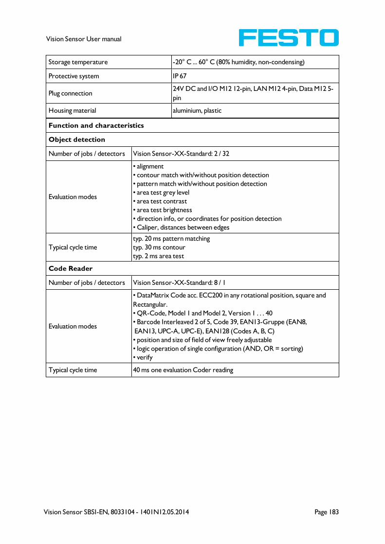
Vision Sensor SBSI-EN, 8033104 - 1401N12.05.2014 Page 183
Vision Sensor User manual
Storage temperature -20° C ... 60° C (80% humidity, non-condensing)
Protective system IP 67
Plug connection24V DC and I/O M12 12-pin, LAN M12 4-pin, Data M12 5-
pin
Housing material aluminium, plastic
Function and characteristics
Object detection
Number of jobs / detectors Vision Sensor-XX-Standard: 2 / 32
Evaluation modes
• alignment
• contour match with/without position detection
• pattern match with/without position detection
• area test grey level
• area test contrast
• area test brightness
• direction info, or coordinates for position detection
• Caliper, distances between edges
Typical cycle time
typ. 20 ms pattern matching
typ. 30 ms contour
typ. 2 ms area test
Code Reader
Number of jobs / detectors Vision Sensor-XX-Standard: 8 / 1
Evaluation modes
• DataMatrix Code acc. ECC200 in any rotational position, square and
Rectangular.
• QR-Code, Model 1 and Model 2, Version 1 . . . 40
• Barcode Interleaved 2 of 5, Code 39, EAN13-Gruppe (EAN8,
EAN13, UPC-A, UPC-E), EAN128 (Codes A, B, C)
• position and size of field of view freely adjustable
• logic operation of single configuration (AND, OR = sorting)
• verify
Typical cycle time 40 ms one evaluation Coder reading
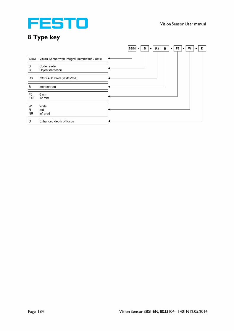
Page 184 Vision Sensor SBSI-EN, 8033104 - 1401N12.05.2014
Vision Sensor User manual
8 Type key
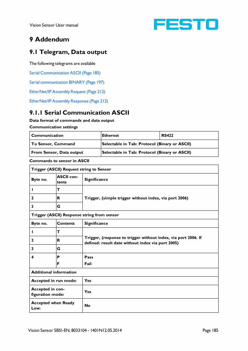
Vision Sensor SBSI-EN, 8033104 - 1401N12.05.2014 Page 185
Vision Sensor User manual
9 Addendum
9.1 Telegram, Data output
The following telegrams are available
Serial Communication ASCII (Page 185)
Serial communication BINARY (Page 197)
EtherNet/IP Assembly Request (Page 212)
EtherNet/IP Assembly Response (Page 212)
9.1.1 Serial Communication ASCIIData format of commands and data output
Communication settings
Communication Ethernet RS422
To Sensor, Command Selectable in Tab: Protocol (Binary or ASCII)
From Sensor, Data output Selectable in Tab: Protocol (Binary or ASCII)
Commands to sensor in ASCII
Trigger (ASCII) Request string to Sensor
Byte no.ASCII con-
tentsSignificance
1 T
Trigger, (simple trigger without index, via port 2006)2 R
3 G
Trigger (ASCII) Response string from sensor
Byte no. Contents Significance
1 T
Trigger, (response to trigger without index, via port 2006. If
defined: result date without index via port 2005)2 R
3 G
4 P
F
Pass
Fail
Additional information
Accepted in run mode: Yes
Accepted in con-
figuration mode:Yes
Accepted when Ready
Low:No

Page 186 Vision Sensor SBSI-EN, 8033104 - 1401N12.05.2014
Vision Sensor User manual
Status of Ready signal
during processing:Low
End of telegram max. 4 byte (option)
Extended Trigger (ASCII) Request string to Sensor
Byte no.ASCII con-
tentsSignificance
1 T
Extended Trigger, (trigger with index, for correlation of trigger to the corresponding res-
ult data, via port 2006)2 R
3 X
4 xLength of following data (n)
5 x
6...n x Data
Extended Trigger (ASCII) Response string from sensor
Byte no.ASCII con-
tentsSignificance
1 TExtended Trigger, (reponse to trigger with index and result data, via port 2006, for cor-
relation of trigger to the corresponding result. Result data without index via port 2005
also)
2 R
3 X
4P
F
Pass
Fail
5 xLength of following data (n)
6 x
7...n x Data of request command
n+1 xC = Config
R = Run
n+2 x
Length of following result data (m)
n+3 x
n+4 x
n+5 x
n+6 x
n+7 x
n+8 x
n+9 x
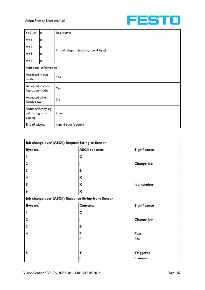
Vision Sensor SBSI-EN, 8033104 - 1401N12.05.2014 Page 187
Vision Sensor User manual
n+9...m x Result data
m+1 x
End of telegram (option, max 4 byte)m+2 x
m+3 x
m+4 x
Additional information
Accepted in run
mode:Yes
Accepted in con-
figuration mode:Yes
Accepted when
Ready Low:No
Status of Ready sig-
nal during pro-
cessing:
Low
End of telegram max. 4 byte (option)
Job change-over (ASCII) Request String to Sensor
Byte no. ASCII contents Significance
1 C
Change Job2 J
3 B
4 X
Job number5 X
6 X
Job change-over (ASCII) Response String from Sensor
Byte no. Contents Significance
1 C
Change Job2 J
3 B
4 P
F
Pass
Fail
5 T
F
Triggered
Free-run

Page 188 Vision Sensor SBSI-EN, 8033104 - 1401N12.05.2014
Vision Sensor User manual
6 X
Job number7 X
8 X
Additional information:
Accepted in run mode: Yes
Accepted in configuration mode: No
Accepted when Ready Low: Yes
Status of Ready signal during processing: Low
End of telegram max. 4 byte (option)
Set parameter (ASCII)
Byte No. Contents Significance
1 SSet parameter
2 P
3 P
T
P Permanent
T Temporary
4 X
Detector No.5 X
6 X
7 X
Parameter No.
101 = Reference string8 X
9 X
10 X
Length of reference string in Bytes (n)
11 X
12 X
13 X
14 X
15...n X New reference string
Set parameter (ASCII) Response string from Sensor
Byte No. Contents ASCII Significance
1 SSet parameter
2 P
3 P
T
P Permanent
T Temporary
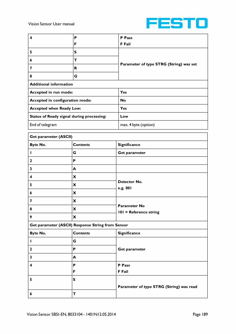
Vision Sensor SBSI-EN, 8033104 - 1401N12.05.2014 Page 189
Vision Sensor User manual
4 P
F
P Pass
F Fail
5 S
Parameter of type STRG (String) was set6 T
7 R
8 G
Additional information
Accepted in run mode: Yes
Accepted in configuration mode: No
Accepted when Ready Low: Yes
Status of Ready signal during processing: Low
End of telegram max. 4 byte (option)
Get parameter (ASCII)
Byte No. Contents Significance
1 G Get parameter
2 P
3 A
4 X
Detector No.
e.g. 0015 X
6 X
7 X
Parameter No
101 = Reference string8 X
9 X
Get parameter (ASCII) Response String from Sensor
Byte No. Contents Significance
1 G
Get parameter2 P
3 A
4 P
F
P Pass
F Fail
5 S
Parameter of type STRG (String) was read
6 T
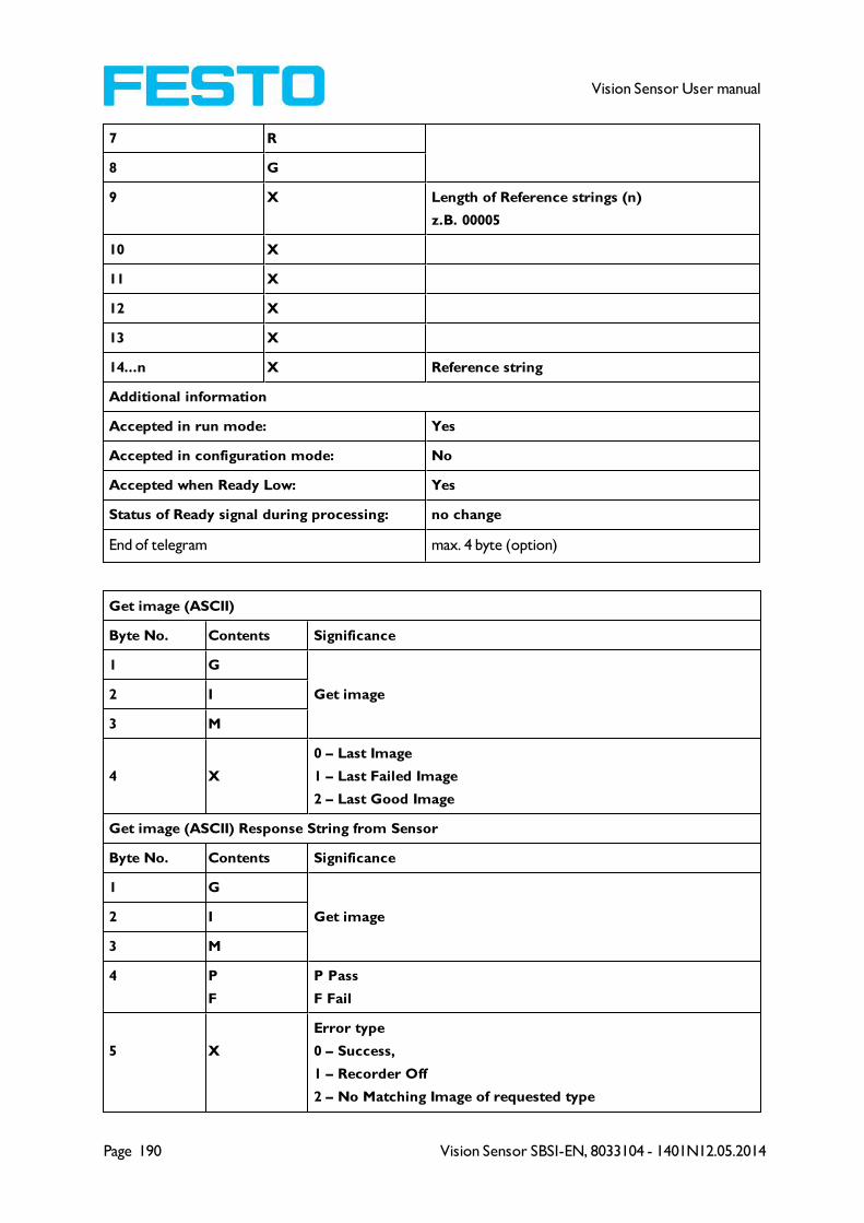
Page 190 Vision Sensor SBSI-EN, 8033104 - 1401N12.05.2014
Vision Sensor User manual
7 R
8 G
9 X Length of Reference strings (n)
z.B. 00005
10 X
11 X
12 X
13 X
14...n X Reference string
Additional information
Accepted in run mode: Yes
Accepted in configuration mode: No
Accepted when Ready Low: Yes
Status of Ready signal during processing: no change
End of telegram max. 4 byte (option)
Get image (ASCII)
Byte No. Contents Significance
1 G
Get image2 I
3 M
4 X
0 – Last Image
1 – Last Failed Image
2 – Last Good Image
Get image (ASCII) Response String from Sensor
Byte No. Contents Significance
1 G
Get image2 I
3 M
4 P
F
P Pass
F Fail
5 X
Error type
0 – Success,
1 – Recorder Off
2 – No Matching Image of requested type
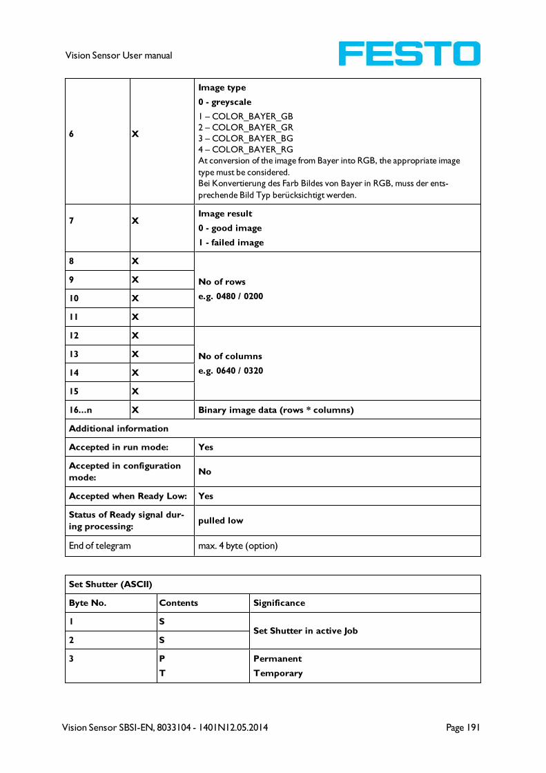
Vision Sensor SBSI-EN, 8033104 - 1401N12.05.2014 Page 191
Vision Sensor User manual
6 X
Image type
0 - greyscale
1 – COLOR_BAYER_GB
2 – COLOR_BAYER_GR
3 – COLOR_BAYER_BG
4 – COLOR_BAYER_RG
At conversion of the image from Bayer into RGB, the appropriate image
type must be considered.
Bei Konvertierung des Farb Bildes von Bayer in RGB, muss der ents-
prechende Bild Typ berücksichtigt werden.
7 XImage result
0 - good image
1 - failed image
8 X
No of rows
e.g. 0480 / 0200
9 X
10 X
11 X
12 X
No of columns
e.g. 0640 / 0320
13 X
14 X
15 X
16...n X Binary image data (rows * columns)
Additional information
Accepted in run mode: Yes
Accepted in configuration
mode:No
Accepted when Ready Low: Yes
Status of Ready signal dur-
ing processing:pulled low
End of telegram max. 4 byte (option)
Set Shutter (ASCII)
Byte No. Contents Significance
1 SSet Shutter in active Job
2 S
3 P
T
Permanent
Temporary
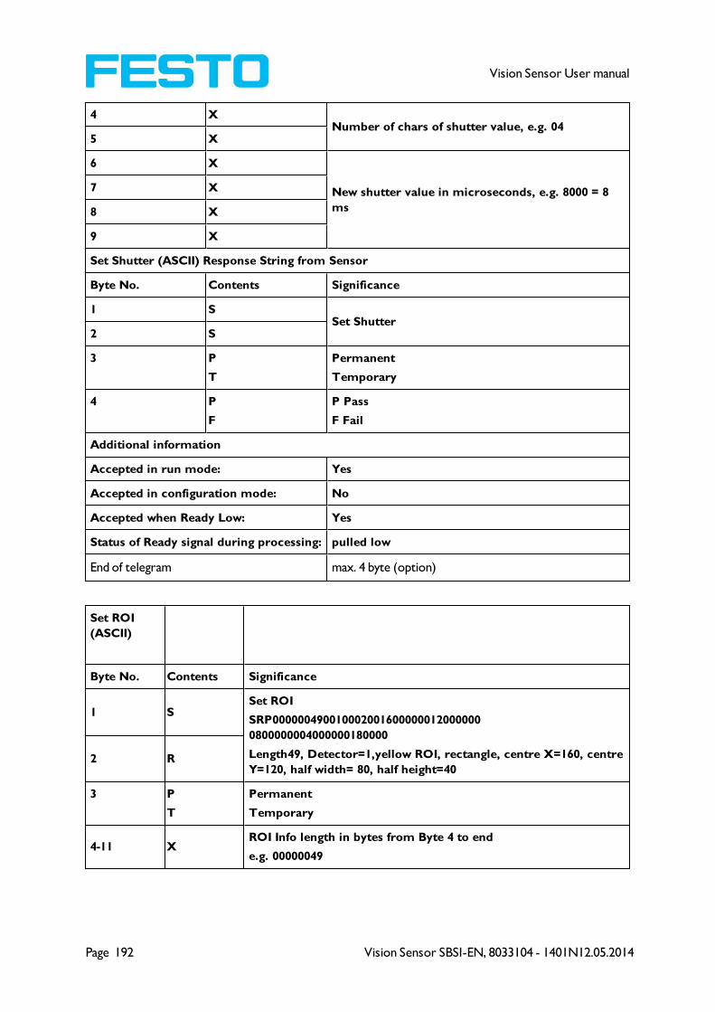
Page 192 Vision Sensor SBSI-EN, 8033104 - 1401N12.05.2014
Vision Sensor User manual
4 XNumber of chars of shutter value, e.g. 04
5 X
6 X
New shutter value in microseconds, e.g. 8000 = 8
ms
7 X
8 X
9 X
Set Shutter (ASCII) Response String from Sensor
Byte No. Contents Significance
1 SSet Shutter
2 S
3 P
T
Permanent
Temporary
4 P
F
P Pass
F Fail
Additional information
Accepted in run mode: Yes
Accepted in configuration mode: No
Accepted when Ready Low: Yes
Status of Ready signal during processing: pulled low
End of telegram max. 4 byte (option)
Set ROI
(ASCII)
Byte No. Contents Significance
1 SSet ROI
SRP000000490010002001600000012000000
0800000004000000180000
Length49, Detector=1,yellow ROI, rectangle, centre X=160, centre
Y=120, half width= 80, half height=402 R
3 P
T
Permanent
Temporary
4-11 XROI Info length in bytes from Byte 4 to end
e.g. 00000049
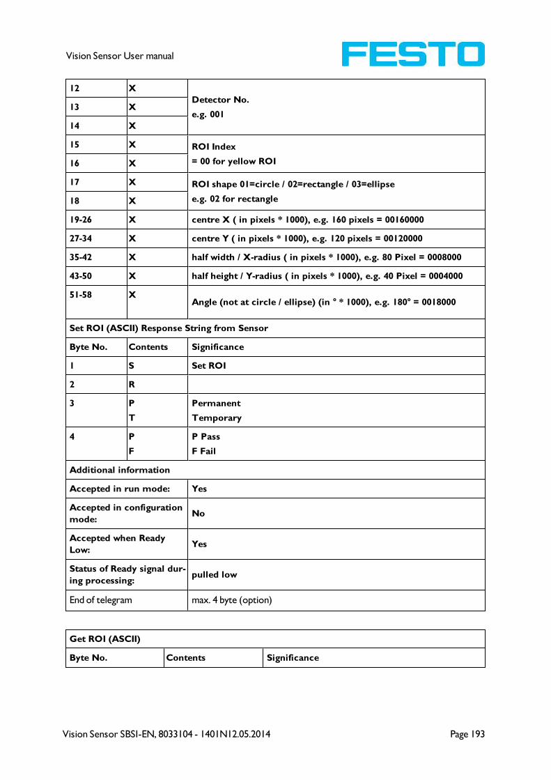
Vision Sensor SBSI-EN, 8033104 - 1401N12.05.2014 Page 193
Vision Sensor User manual
12 X
Detector No.
e.g. 00113 X
14 X
15 X ROI Index
= 00 for yellow ROI16 X
17 X ROI shape 01=circle / 02=rectangle / 03=ellipse
e.g. 02 for rectangle18 X
19-26 X centre X ( in pixels * 1000), e.g. 160 pixels = 00160000
27-34 X centre Y ( in pixels * 1000), e.g. 120 pixels = 00120000
35-42 X half width / X-radius ( in pixels * 1000), e.g. 80 Pixel = 0008000
43-50 X half height / Y-radius ( in pixels * 1000), e.g. 40 Pixel = 0004000
51-58 XAngle (not at circle / ellipse) (in ° * 1000), e.g. 180° = 0018000
Set ROI (ASCII) Response String from Sensor
Byte No. Contents Significance
1 S Set ROI
2 R
3 P
T
Permanent
Temporary
4 P
F
P Pass
F Fail
Additional information
Accepted in run mode: Yes
Accepted in configuration
mode:No
Accepted when Ready
Low:Yes
Status of Ready signal dur-
ing processing:pulled low
End of telegram max. 4 byte (option)
Get ROI (ASCII)
Byte No. Contents Significance

Page 194 Vision Sensor SBSI-EN, 8033104 - 1401N12.05.2014
Vision Sensor User manual
1 G
Get ROI
e.g. GRI001002 R
3 I
4 X
Detector No.
e.g. 0015 X
6 X
7 X ROI Index
= 00 for yellow ROI8 X
Get ROI (ASCII) Response String from Sensor
Byte No. Contents Significance
1 G
Get ROI2 R
3 I
4 P
F
P Pass
F Fail
5 XROI Info length in bytes from Byte 5 to end
6 X
7 X
Detector No.8 X
9 X
10 X ROI Index
= 00 for yellow ROI11 X
12 XROI shape 01=circle / 02=rectangle / 03=ellipse
13 X
14-21 X centre X ( in pixels * 1000)
22-29 X centre Y ( in pixels * 1000)
30-37 X X-radius ( in pixels * 1000)
38-45 X Y-radius ( in pixels * 1000)
46-53 X Angle (not at circle / ellipse) (in ° * 1000)
Additional information
Accepted in run mode: Yes
Accepted in configuration mode: No
Accepted when Ready Low: Yes

Vision Sensor SBSI-EN, 8033104 - 1401N12.05.2014 Page 195
Vision Sensor User manual
Status of Ready signal during processing: pulled low
End of telegram max. 4 byte (option)
Data output in ASCII
Dynamically composed from user settings in the software
<START> (((<OPTIONAL FIELDS> <SEPARATOR> <PAYLOAD>))) <CHKSUM> <TRAILER>
Output data (ASCII), dynamically composed from user settings in the software
NameNumber
of bytes
ASCII contents /
exampleSignificance /Comments
Header1 - max.
8
User defined,
max. 8 char-
acters
Start string (Header)
Separator 1 - 5
User defined,
max. 5 char-
acters (per sep-
arator)
Separator from:
“after first optional field“, or
„after first detector spec. date“
Selected Fields 16 1 Byte per field
by this field output of all active checkboxes "byte-
wise" can be activated
- Output order is from left to right and from top
to down.
- For each checkbox there is one byte beginning
with LSB = low significant bit.
- Checkbox "Selected fields" is not part of the out-
put!
P = logical output set
F = logical output not set
0 = logical output not active
Data length n
One byte per fig-
ure of decimal
number
e.g. 102 „1“;
„0“; „2“
Length of telegram in bytes
Status3
“110” triggered
mode
or
“101” free-run
mode
Detector result n
Byte 1 = AND
conjunction of
all detectors
Byte 2 =
Boolean result
of alignment
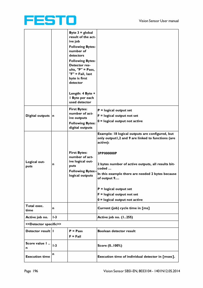
Page 196 Vision Sensor SBSI-EN, 8033104 - 1401N12.05.2014
Vision Sensor User manual
Byte 3 = global
result of the act-
ive job
Following Bytes:
number of
detectors
Following Bytes:
Detector res-
ults, "P" = Pass,
"F" = Fail, last
byte is first
detector
Length: 4 Byte +
1 Byte per each
used detector
Digital outputs n
First Bytes:
number of act-
ive outputs
Following Bytes:
digital outputs
P = logical output set
F = logical output not set
0 = logical output not active
Logical out-
putsn
First Bytes:
number of act-
ive logical out-
puts
Following Bytes:-
logical outputs
Example: 18 logical outputs are configured, but
only output1,2 and 9 are linked to functions (are
active):
3PP000000P
2 bytes number of active outputs, all results bit-
coded ...
In this example there are needed 2 bytes because
of output 9....
P = logical output set
F = logical output not set
0 = logical output not active
Total exec.
timen Current (job) cycle time in [ms]
Active job no. 1-3 Active job no. (1..255)
<<Detector specific>>
Detector result 1 P = Pass
F = Fail
Boolean detector result
Score value 1 ..
n1-3 Score (0..100%)
Execution timen
Execution time of individual detector in [msec].
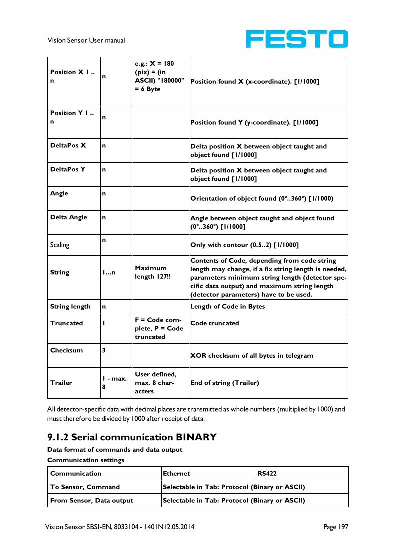
Vision Sensor SBSI-EN, 8033104 - 1401N12.05.2014 Page 197
Vision Sensor User manual
Position X 1 ..
nn
e.g.: X = 180
(pix) = (in
ASCII) "180000"
= 6 BytePosition found X (x-coordinate). [1/1000]
Position Y 1 ..
nn
Position found Y (y-coordinate). [1/1000]
DeltaPos X n Delta position X between object taught and
object found [1/1000]
DeltaPos Y n Delta position X between object taught and
object found [1/1000]
Angle nOrientation of object found (0°..360°) [1/1000)
Delta Angle n Angle between object taught and object found
(0°..360°) [1/1000]
Scalingn
Only with contour (0.5..2) [1/1000]
String 1...nMaximum
length 127!!
Contents of Code, depending from code string
length may change, if a fix string length is needed,
parameters minimum string length (detector spe-
cific data output) and maximum string length
(detector parameters) have to be used.
String length n Length of Code in Bytes
Truncated 1F = Code com-
plete, P = Code
truncated
Code truncated
Checksum 3XOR checksum of all bytes in telegram
Trailer1 - max.
8
User defined,
max. 8 char-
acters
End of string (Trailer)
All detector-specific data with decimal places are transmitted as whole numbers (multiplied by 1000) and
must therefore be divided by 1000 after receipt of data.
9.1.2 Serial communication BINARYData format of commands and data output
Communication settings
Communication Ethernet RS422
To Sensor, Command Selectable in Tab: Protocol (Binary or ASCII)
From Sensor, Data output Selectable in Tab: Protocol (Binary or ASCII)

Page 198 Vision Sensor SBSI-EN, 8033104 - 1401N12.05.2014
Vision Sensor User manual
Commands to sensor in BINARY
Trigger (Binary) Request string to sensor
Byte
no.
Data
typeContents Significance
1Unsigned
Int0x00
Length of telegram2 0x00
3 0x00
4 0x05
5Unsigned
Char0x01 Trigger command, (simple trigger without index, via port 2006)
Trigger (Binary) Answer string from sensor
Byte
no.
Data
typeContents Significance
1Unsigned
Int0x00
Length of telegram2 0x00
3 0x00
4 0x07
5Unsigned
Char0x01
Trigger command, (response to trigger without index, via port
2006. If defined: result data without index via port 2005)
6Unsigned
Short0x00
Error code, 0 = Pass, 1 = Fail
7 0xXX
Additional information
Accepted in run mode: Yes
Accepted in configuration
mode:Yes
Accepted when Ready Low: No
Status of Ready signal dur-
ing processing:Low
Extended Trigger (Binary) Request string to sensor
Byte
no.
Data
typeContents Significance
1Unsigned
Int0x00 Length of telegram
2 0x00

Vision Sensor SBSI-EN, 8033104 - 1401N12.05.2014 Page 199
Vision Sensor User manual
3 0x00
4 0x05
5Unsigned
Char0x013
Extended Trigger command, (trigger with index for correlation of
trigger to the correponding result data, via port 2006)
6Unsigned
Char0xXX Length of following data (n)
7...nUnsigned
Char0xXX Data
Extended Trigger (Binary) Answer string from sensor
Byte
no.
Data
typeContents Significance
1Unsigned
Int0x00
Length of telegram2 0x00
3 0x00
4 0x07
5Unsigned
Char0x013
Extended Trigger command, (response to trigger with index and
result data, via port 2006, for correlation of trigger to cor-
responding result, Result data without index, via port 2005 also)
6 Unsigned
Short
0x00Error code
0 = Pass
1 = Fail7 0xXX
8Unsigned
Char0xXX Length of following data (n)
9...nUnsigned
Char0xXX Data of request command
n+1Unsigned
Char []0xXX
Operating mode
0 = Config Mode
1 = Run Mode
n+2
Unsigned
Int
0xXX
Length of following result data (m)n+3 0xXX
n+4 0xXX
n+5 0xXX
n+6
Unsigned
Int []
0xXX
Result datan+7 0xXX
n+8 0xXX
n+9...m 0xXX
Additional information
Accepted in run mode: Yes
Accepted in configuration Yes
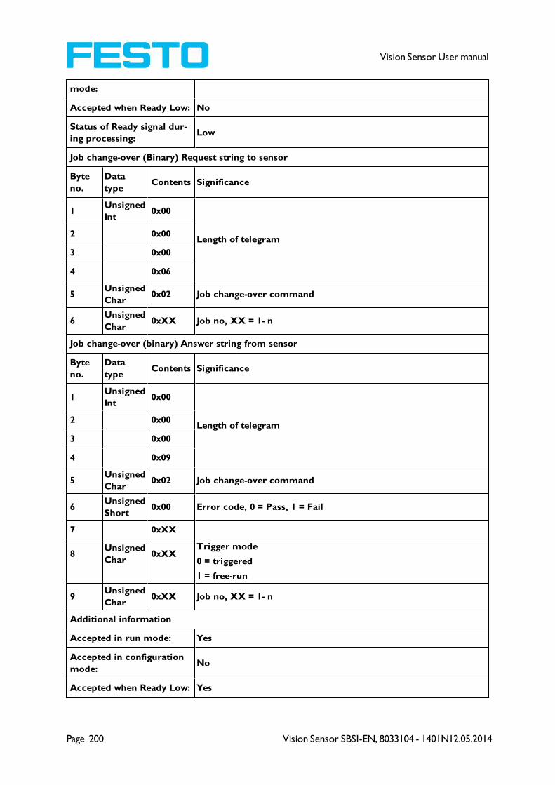
Page 200 Vision Sensor SBSI-EN, 8033104 - 1401N12.05.2014
Vision Sensor User manual
mode:
Accepted when Ready Low: No
Status of Ready signal dur-
ing processing:Low
Job change-over (Binary) Request string to sensor
Byte
no.
Data
typeContents Significance
1Unsigned
Int0x00
Length of telegram2 0x00
3 0x00
4 0x06
5Unsigned
Char0x02 Job change-over command
6Unsigned
Char0xXX Job no, XX = 1- n
Job change-over (binary) Answer string from sensor
Byte
no.
Data
typeContents Significance
1Unsigned
Int0x00
Length of telegram2 0x00
3 0x00
4 0x09
5Unsigned
Char0x02 Job change-over command
6Unsigned
Short0x00 Error code, 0 = Pass, 1 = Fail
7 0xXX
8Unsigned
Char0xXX
Trigger mode
0 = triggered
1 = free-run
9Unsigned
Char0xXX Job no, XX = 1- n
Additional information
Accepted in run mode: Yes
Accepted in configuration
mode:No
Accepted when Ready Low: Yes
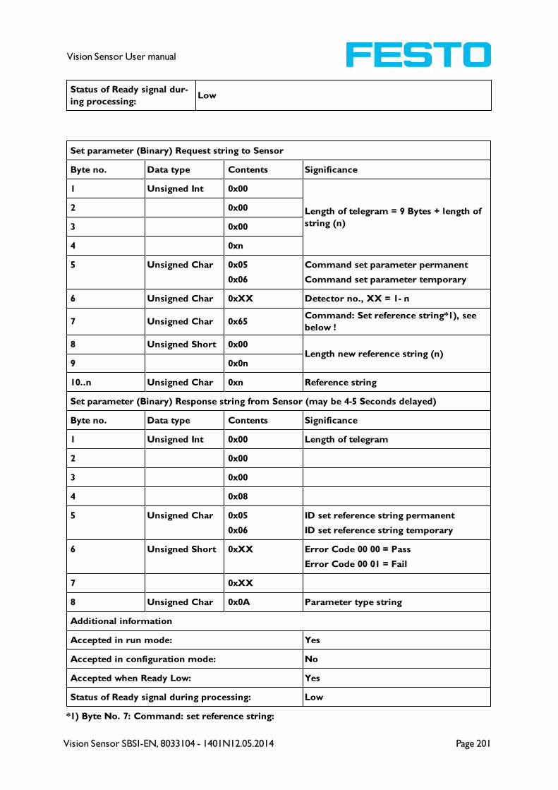
Vision Sensor SBSI-EN, 8033104 - 1401N12.05.2014 Page 201
Vision Sensor User manual
Status of Ready signal dur-
ing processing:Low
Set parameter (Binary) Request string to Sensor
Byte no. Data type Contents Significance
1 Unsigned Int 0x00
Length of telegram = 9 Bytes + length of
string (n)
2 0x00
3 0x00
4 0xn
5 Unsigned Char 0x05
0x06
Command set parameter permanent
Command set parameter temporary
6 Unsigned Char 0xXX Detector no., XX = 1- n
7 Unsigned Char 0x65Command: Set reference string*1), see
below !
8 Unsigned Short 0x00Length new reference string (n)
9 0x0n
10..n Unsigned Char 0xn Reference string
Set parameter (Binary) Response string from Sensor (may be 4-5 Seconds delayed)
Byte no. Data type Contents Significance
1 Unsigned Int 0x00 Length of telegram
2 0x00
3 0x00
4 0x08
5 Unsigned Char 0x05
0x06
ID set reference string permanent
ID set reference string temporary
6 Unsigned Short 0xXX Error Code 00 00 = Pass
Error Code 00 01 = Fail
7 0xXX
8 Unsigned Char 0x0A Parameter type string
Additional information
Accepted in run mode: Yes
Accepted in configuration mode: No
Accepted when Ready Low: Yes
Status of Ready signal during processing: Low
*1) Byte No. 7: Command: set reference string:
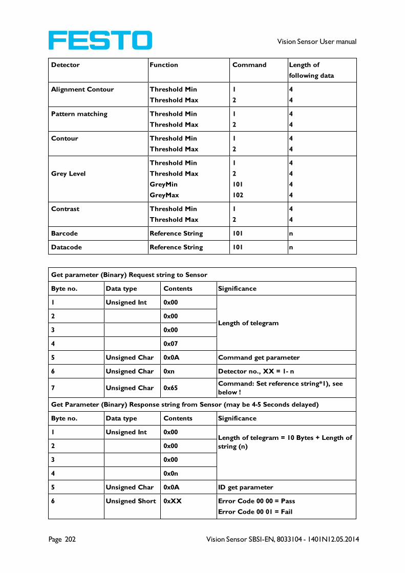
Page 202 Vision Sensor SBSI-EN, 8033104 - 1401N12.05.2014
Vision Sensor User manual
Detector Function Command Length of
following data
Alignment Contour Threshold Min
Threshold Max
1
2
4
4
Pattern matching Threshold Min
Threshold Max
1
2
4
4
Contour Threshold Min
Threshold Max
1
2
4
4
Grey Level
Threshold Min
Threshold Max
GreyMin
GreyMax
1
2
101
102
4
4
4
4
Contrast Threshold Min
Threshold Max
1
2
4
4
Barcode Reference String 101 n
Datacode Reference String 101 n
Get parameter (Binary) Request string to Sensor
Byte no. Data type Contents Significance
1 Unsigned Int 0x00
Length of telegram2 0x00
3 0x00
4 0x07
5 Unsigned Char 0x0A Command get parameter
6 Unsigned Char 0xn Detector no., XX = 1- n
7 Unsigned Char 0x65Command: Set reference string*1), see
below !
Get Parameter (Binary) Response string from Sensor (may be 4-5 Seconds delayed)
Byte no. Data type Contents Significance
1 Unsigned Int 0x00Length of telegram = 10 Bytes + Length of
string (n)2 0x00
3 0x00
4 0x0n
5 Unsigned Char 0x0A ID get parameter
6 Unsigned Short 0xXX Error Code 00 00 = Pass
Error Code 00 01 = Fail
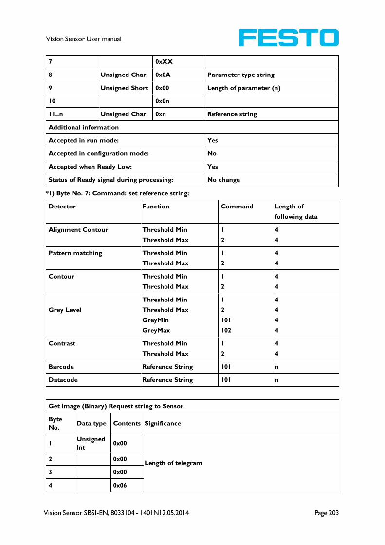
Vision Sensor SBSI-EN, 8033104 - 1401N12.05.2014 Page 203
Vision Sensor User manual
7 0xXX
8 Unsigned Char 0x0A Parameter type string
9 Unsigned Short 0x00 Length of parameter (n)
10 0x0n
11..n Unsigned Char 0xn Reference string
Additional information
Accepted in run mode: Yes
Accepted in configuration mode: No
Accepted when Ready Low: Yes
Status of Ready signal during processing: No change
*1) Byte No. 7: Command: set reference string:
Detector Function Command Length of
following data
Alignment Contour Threshold Min
Threshold Max
1
2
4
4
Pattern matching Threshold Min
Threshold Max
1
2
4
4
Contour Threshold Min
Threshold Max
1
2
4
4
Grey Level
Threshold Min
Threshold Max
GreyMin
GreyMax
1
2
101
102
4
4
4
4
Contrast Threshold Min
Threshold Max
1
2
4
4
Barcode Reference String 101 n
Datacode Reference String 101 n
Get image (Binary) Request string to Sensor
Byte
No.Data type Contents Significance
1Unsigned
Int0x00
Length of telegram2 0x00
3 0x00
4 0x06
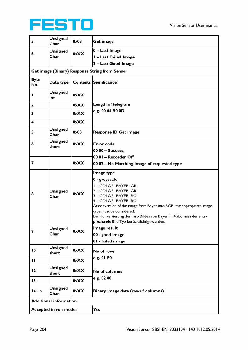
Page 204 Vision Sensor SBSI-EN, 8033104 - 1401N12.05.2014
Vision Sensor User manual
5Unsigned
Char0x03 Get image
6Unsigned
Char0xXX
0 – Last Image
1 – Last Failed Image
2 – Last Good Image
Get image (Binary) Response String from Sensor
Byte
No.Data type Contents Significance
1Unsigned
Int0xXX
Length of telegram
e.g. 00 04 B0 0D
2 0xXX
3 0xXX
4 0xXX
5Unsigned
Char0x03 Response ID Get image
6Unsigned
short0xXX Error code
00 00 – Success,
00 01 – Recorder Off
00 02 – No Matching Image of requested type7 0xXX
8Unsigned
Char0xXX
Image type
0 - greyscale
1 – COLOR_BAYER_GB
2 – COLOR_BAYER_GR
3 – COLOR_BAYER_BG
4 – COLOR_BAYER_RG
At conversion of the image from Bayer into RGB, the appropriate image
type must be considered.
Bei Konvertierung des Farb Bildes von Bayer in RGB, muss der ents-
prechende Bild Typ berücksichtigt werden.
9Unsigned
Char0xXX
Image result
00 - good image
01 - failed image
10Unsigned
short0xXX No of rows
e.g. 01 E011 0xXX
12Unsigned
short0xXX No of columns
e.g. 02 8013 0xXX
14...nUnsigned
Char0xXX Binary image data (rows * columns)
Additional information
Accepted in run mode: Yes
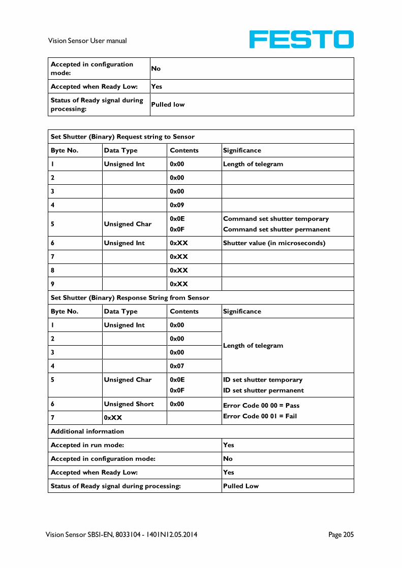
Vision Sensor SBSI-EN, 8033104 - 1401N12.05.2014 Page 205
Vision Sensor User manual
Accepted in configuration
mode:No
Accepted when Ready Low: Yes
Status of Ready signal during
processing:Pulled low
Set Shutter (Binary) Request string to Sensor
Byte No. Data Type Contents Significance
1 Unsigned Int 0x00 Length of telegram
2 0x00
3 0x00
4 0x09
5 Unsigned Char0x0E
0x0F
Command set shutter temporary
Command set shutter permanent
6 Unsigned Int 0xXX Shutter value (in microseconds)
7 0xXX
8 0xXX
9 0xXX
Set Shutter (Binary) Response String from Sensor
Byte No. Data Type Contents Significance
1 Unsigned Int 0x00
Length of telegram2 0x00
3 0x00
4 0x07
5 Unsigned Char 0x0E
0x0F
ID set shutter temporary
ID set shutter permanent
6 Unsigned Short 0x00 Error Code 00 00 = Pass
Error Code 00 01 = Fail7 0xXX
Additional information
Accepted in run mode: Yes
Accepted in configuration mode: No
Accepted when Ready Low: Yes
Status of Ready signal during processing: Pulled Low

Page 206 Vision Sensor SBSI-EN, 8033104 - 1401N12.05.2014
Vision Sensor User manual
Set ROI (Binary) Request string to Sensor
Byte No. Data Type Contents Significance
1 Unsigned Int 0x00
Length of telegram2 0x00
3 0x00
4 0x32
5Unsigned
Char0x10
0x11
Command set ROI temporary
Command set ROI permanent
6 Unsigned Int 0xXX
ROI Info Length in Bytes from Byte 6 to end7 0xXX
8 0xXX
9 0xXX
10Unsigned
Char0xXX Detector No.
11Unsigned
Char0x00 ROI Index = 00 = yellow ROI
12Unsigned
Char0xXX ROI shape 01=circle / 02=rectangle / 03=ellipse
13 Unsigned Int 0xXX
ROI Parameter: centre X (in Pixels * 1000)14 0xXX
15 0xXX
16 0xXX
17 Unsigned Int 0xXX
ROI Parameter: centre Y (in Pixels * 1000)18 0xXX
19 0xXX
20 0xXX
21 Unsigned Int 0xXX
ROI Parameter: width / radius X (in Pixels* 1000)22 0xXX
23 0xXX
24 0xXX
25 Unsigned Int 0xXX
Only ellipse / rectangle: ROI Parameter: width / radius Y
(in Pixels* 1000)26 0xXX
27 0xXX
28 0xXX
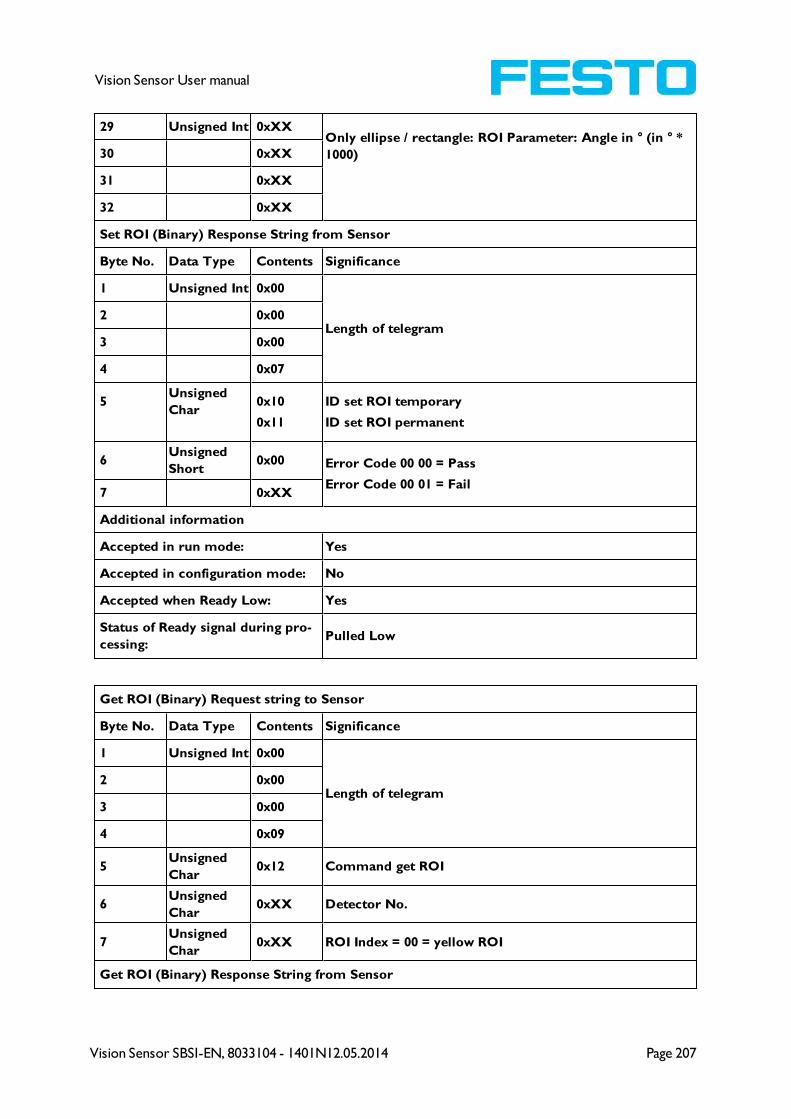
Vision Sensor SBSI-EN, 8033104 - 1401N12.05.2014 Page 207
Vision Sensor User manual
29 Unsigned Int 0xXXOnly ellipse / rectangle: ROI Parameter: Angle in ° (in ° *
1000)30 0xXX
31 0xXX
32 0xXX
Set ROI (Binary) Response String from Sensor
Byte No. Data Type Contents Significance
1 Unsigned Int 0x00
Length of telegram2 0x00
3 0x00
4 0x07
5Unsigned
Char0x10
0x11
ID set ROI temporary
ID set ROI permanent
6Unsigned
Short0x00 Error Code 00 00 = Pass
Error Code 00 01 = Fail7 0xXX
Additional information
Accepted in run mode: Yes
Accepted in configuration mode: No
Accepted when Ready Low: Yes
Status of Ready signal during pro-
cessing:Pulled Low
Get ROI (Binary) Request string to Sensor
Byte No. Data Type Contents Significance
1 Unsigned Int 0x00
Length of telegram2 0x00
3 0x00
4 0x09
5Unsigned
Char0x12 Command get ROI
6Unsigned
Char0xXX Detector No.
7Unsigned
Char0xXX ROI Index = 00 = yellow ROI
Get ROI (Binary) Response String from Sensor

Page 208 Vision Sensor SBSI-EN, 8033104 - 1401N12.05.2014
Vision Sensor User manual
Byte No. Data Type Contents Significance
1 Unsigned Int 0x00
Length of telegram2 0x00
3 0x00
4 0x34
5Unsigned
Char0x12 ID get ROI
6Unsigned
Short0x00 Error Code 00 00 = Pass
Error Code 00 01 = Fail7 0xXX
8 Unsigned Int 0xXX
ROI Info Length in Bytes from Byte 8 to end9 0xXX
10 0xXX
11 0xXX
12Unsigned
Char0xXX Detector No.
13Unsigned
Char0x00 ROI Index = 00 = yellow ROI
14Unsigned
Char 0xXX ROI shape 01=circle / 02=rectangle / 03=ellipse
15 Unsigned Int 0xXX
ROI Parameter: centre X (in Pixels * 1000)16 0xXX
17 0xXX
18 0xXX
19 Unsigned Int 0xXX
ROI Parameter: centre Y (in Pixels * 1000)20 0xXX
21 0xXX
22 0xXX
23 Unsigned Int 0xXX
ROI Parameter: width / radius X (in Pixels* 1000)24 0xXX
25 0xXX
26 0xXX
27 Unsigned Int 0xXX Only ellipse / rectangle: ROI Parameter: width / radius Y
(in Pixels* 1000)
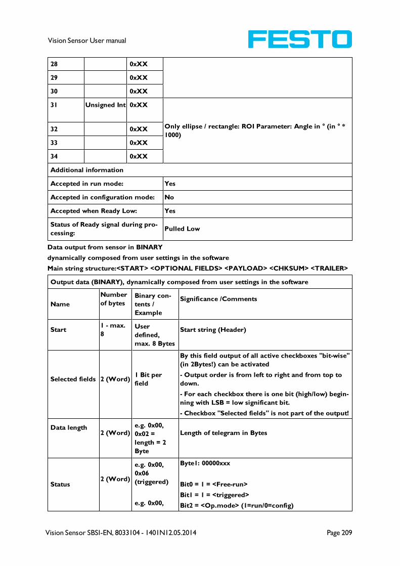
Vision Sensor SBSI-EN, 8033104 - 1401N12.05.2014 Page 209
Vision Sensor User manual
28 0xXX
29 0xXX
30 0xXX
31 Unsigned Int 0xXX
Only ellipse / rectangle: ROI Parameter: Angle in ° (in ° *
1000)32 0xXX
33 0xXX
34 0xXX
Additional information
Accepted in run mode: Yes
Accepted in configuration mode: No
Accepted when Ready Low: Yes
Status of Ready signal during pro-
cessing:Pulled Low
Data output from sensor in BINARY
dynamically composed from user settings in the software
Main string structure:<START> <OPTIONAL FIELDS> <PAYLOAD> <CHKSUM> <TRAILER>
Output data (BINARY), dynamically composed from user settings in the software
Name
Number
of bytesBinary con-
tents /
Example
Significance /Comments
Start1 - max.
8User
defined,
max. 8 Bytes
Start string (Header)
Selected fields 2 (Word)1 Bit per
field
By this field output of all active checkboxes "bit-wise"
(in 2Bytes!) can be activated
- Output order is from left to right and from top to
down.
- For each checkbox there is one bit (high/low) begin-
ning with LSB = low significant bit.
- Checkbox "Selected fields" is not part of the output!
Data length2 (Word)
e.g. 0x00,
0x02 =
length = 2
Byte
Length of telegram in Bytes
Status2 (Word)
e.g. 0x00,
0x06
(triggered)
e.g. 0x00,
Byte1: 00000xxx
Bit0 = 1 = <Free-run>
Bit1 = 1 = <triggered>
Bit2 = <Op.mode> (1=run/0=config)

Page 210 Vision Sensor SBSI-EN, 8033104 - 1401N12.05.2014
Vision Sensor User manual
0x05
(free-run) Byte2 (reserved), always 0x00
Detector res-
ult4..n
e.g..
0x05
(Bit1+3=5)
0x00 (two
bytes num-
ber of detect-
ors) 0x01
0x01
(Detector
result D1)
Byte 1
Bit1 (LSB) = global job result
(1 = Pass, 0 = Fail)
Bit2 = Boolean result, alignment only, alignment
inactive = true
Bit3 = AND conjunction of all detectors of the active
job
Byte 2 and 3 two byes for the number of detectors
inside job (without alignment)
Byte 4 - n
1 Byte per each block of 8 used detectors
e.g.: Bit1(LSB) = Detector 1, Bit2 = Det. 2, ....
Digital out-
putsn
Byte 1 and 2:
number of
active out-
puts
Bytes 3 ... n:
outputs, bit-
coded
Results of all digital outputs (bit-coded)
Logical out-
puts
n
Byte 1 ... n
number of
active logical
outputs
Byte n ... m
all active
logical out-
puts, bit-
coded
Example: 18 logical outputs are configured, but only
output1,2 and 9 are linked to functions (are active):
000, 003, 003, 001
2 bytes number of active outputs, all results bit-coded
...
In this example there are needed 2 bytes because of
output 9....
1. result byte = 00000011 (log. output 1+2)
2. result byte = 00000001 (log. output 9)
Total exec.
time
4
(Integer)Current (job) cycle time in [ms]
Active job no. 1 Active Job no. (1..255)
<<Detector specific>>
Detector res-
ult1
(1 = Pass, 0
= Fail)Boolean detector result
Score value 1
.. n4 Score (0..100%)

Vision Sensor SBSI-EN, 8033104 - 1401N12.05.2014 Page 211
Vision Sensor User manual
Execution
time4 Execution time of individual detector in [msec].
Position X1 ..
n4 Position found X (x-coordinate). [1/1000]
Position Y1 ..
n4 Position found Y (y-coordinate). [1/1000]
DeltaPos X 4 Delta Position X between object taught and object
found [1/1000]
DeltaPos Y 4 Delta Position X between object taught and object
found [1/1000]
Angle 4Orientation of object found (0°..360°) [1/1000)
Delta Angle 4 Angle between object taught and object found
(0°..360°) [1/1000]
Scaling 4 Only with contour (0.5..2) [1/1000]
String 1...nMaximum
length 127!!
Contents of Code, depending from code string length
may change, if a fix string length is needed, para-
meters minimum string length (detector specific data
output) and maximum string length (detector para-
meters) have to be used.
String length 4 Length of Code in Bytes
Truncated 10x00 = Code
complete,
0x01 = Code
truncated
Code truncated
Checksum 1 XOR-checksum of all bytes in telegram
Trailer1 - max.
8End of string (Trailer)
All detector-specific data with decimal places are transmitted as whole numbers (multiplied by
1000) and must therefore be divided by 1000 after receipt of data.
Values are transferred in format "Big-endian". (there are two different architectures for hand-
ling memory storage. They are called Big Endian and Little Endian and refer to the order in
which the bytes are stored in memory, in the case of the Vision Sensor architecture the data is
stored Big End In first)
Example: "Score" Value (Binary protocol)
In Vision Sensor Configuration Studio/Vision Sensor Visualisation Studio "Score" = 35 is dis-
played.
Over Ethernet there will be received the following four bytes: 000,000,139,115
Formula for recalculating: (HiWordByte*256 + HiLowByte) *65536 + HiByte*256 + LoByte =
Value

Page 212 Vision Sensor SBSI-EN, 8033104 - 1401N12.05.2014
Vision Sensor User manual
Because Big-endian (from Sensor) is sent calculation goes as following:
000 = HiWordByte, 000 = HiLowByte, 139 = HiByte, 115 = LoByte
(0*256 + 0) * 65536 + (139 * 256) + 115 = 35699 / 1000 = 35,699 (real score value)
Angles or other negative values are transferred in two's complement.
9.1.3 EtherNet/IP Assembly Request
Communication Settings
Description: Response returned from sensor to PLC
Class: Class 1
nAssemblyInstance 101
nType AssemblyProducing
nLength (bytes) 444
szAssemblyName AssemblyResponse
Assembly request
PositionSize
(bytes)Member
Data
typeDescription
0 2 unKey U16 request key, e.g. a request counter
2 2 unId U16request ID, e.g. for requests "trigger",
"change job"
4 2 unNumChar U16 no. of valid char parameters
6 2 unNumInt U16 no. of valid int parameters
8 256pcValueChar[RQST_
NUM_CHAR]I8
char parameters for request, member may
only hold one string
264 80pnValueInt[RQST_
NUM_INT]I32 int parameters for request
9.1.4 EtherNet/IP Assembly Response
Communication-Settings
Description: Request posted to sensor from PLC
Class: Class 1
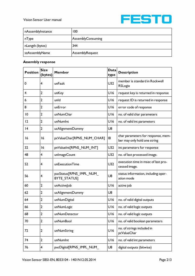
Vision Sensor SBSI-EN, 8033104 - 1401N12.05.2014 Page 213
Vision Sensor User manual
nAssemblyInstance 100
nType AssemblyConsuming
nLength (bytes) 344
szAssemblyName AssemblyRequest
Assembly response
PositionSize
(bytes)Member
Data
typeDescription
0 4 unFault U32member is standard in Rockwell
RSLogix
4 2 unKey U16 request key is returned in response
6 2 unId U16 request ID is returned in response
8 2 unError U16 error code of response
10 2 unNumChar U16 no. of valid char parameters
12 2 unNumInt U16 no. of valid int parameters
14 2 ucAlignmentDummy U8
16 16 pcValueChar[RPNS_NUM_CHAR] I8char parameters for response, mem-
ber may only hold one string
32 16 pnValueInt[RPNS_NUM_INT] U32 int parameters for response
48 4 unImageCount U32 no. of last processed image.
52 4 unExecutionTime U32execution time in msec of last pro-
cessed image.
56 4pucStatus[RPNS_IMPL_NUM_
BYTE_STATUS]U8
status information, including oper-
ation mode
60 2 unActiveJob U16 active job
62 2 ucAlignmentDummy U8
64 2 unNumDigital U16 no. of valid digital outputs
66 2 unNumLogic U16 no. of valid logic outputs
68 2 unNumDetector U16 no. of valid logic outputs
70 2 unNumBool U16 no. of valid boolean parameters
72 2 unNumString U16no. of strings included in
pcValueChar
74 2 unNumInt U16 no. of valid int parameters
76 4 pucDigital[RPNS_IMPL_NUM_ U8 digital outputs (bitwise)

Page 214 Vision Sensor SBSI-EN, 8033104 - 1401N12.05.2014
Vision Sensor User manual
BYTE_DIGITAL]
80 8pucLogic[RPNS_IMPL_NUM_
BYTE_LOGIC]U8 logic outputs (bitwise)
88 4pucDetector[RPNS_IMPL_NUM_
BYTE_DETECTOR]U8
detector results (bitwise), formerly
stored in pucValueBool
92 4pucBool[RPNS_IMPL_NUM_
BYTE_BOOL]U8
boolean results (bitwise) as con-
figured in HMI (listbox)
96 16punStringLength[RPNS_IMPL_
NUM_STRING]U16
lengths of strings included in
pcValueChar
112 2
pucStringTruncated[RPNS_IMPL_
NUM_BYTE_STRING_
TRUNCATED]
U8indicates for each string whether it
has been truncated (bitwise)
114 2 ucAlignmentDummy U8
116 128pcString[RPNS_IMPL_NUM_
BYTE_STRING]I8
char result as configured in HMI (list-
box), member may hold multiple
strings
244 200 pnInt[RPNS_IMPL_NUM_INT] U32int results as configured in HMI (list-
box)
9.2 Starting Vision Sensor Visualisation Studio or Vision Sensor
Configuration Studio via Autostart
To start Vision Sensor Visualisation Studio or Vision Sensor Configuration Studio via Autostart please
select in: Vision Sensor Device Manager/File/Auto start file, the module to autostart and save it.
After selecting the module to start and the user level, with "Save" store the Autostart- file in folder
..\Windows\Start Menu\Programs (exact path depends on Windows installation)
9.3 Care and maintainance
9.3.1 Cleaning
The Vision Sensor is to be cleaned with a clean, dry cloth.
Dirt on the front panel is to be cleaned with a soft cloth and a small amount of plastic cleaner if necessary.
Attention
Never use aggressive detergents such as solvents or benzine.
Never use sharp objects. Do not scratch!
9.3.2 Transport, packaging, storage
Always check the delivery contents immediately after receipt to ensure they are complete and that they
have not been damaged during transport. In the event of transport damage, the carrier must be informed.
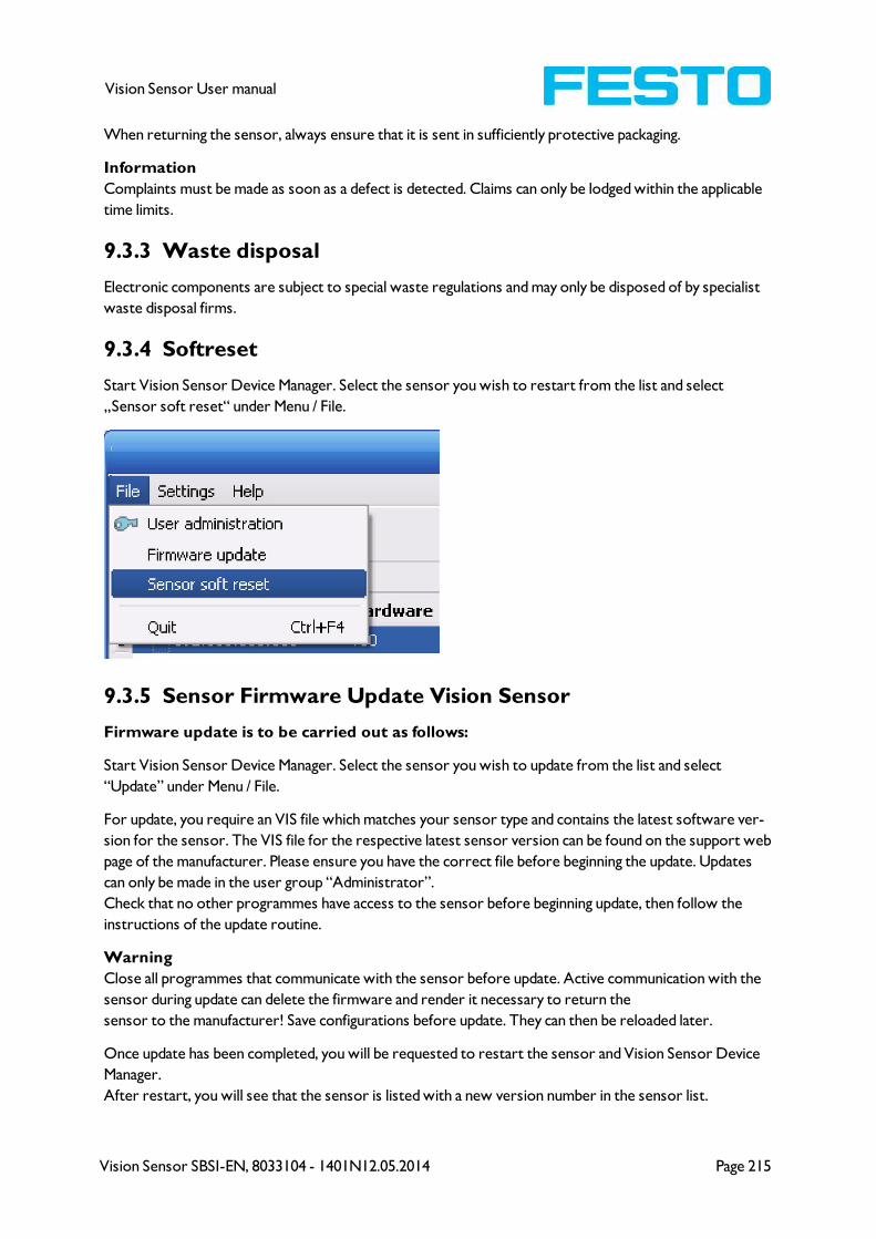
Vision Sensor SBSI-EN, 8033104 - 1401N12.05.2014 Page 215
Vision Sensor User manual
When returning the sensor, always ensure that it is sent in sufficiently protective packaging.
Information
Complaints must be made as soon as a defect is detected. Claims can only be lodged within the applicable
time limits.
9.3.3 Waste disposal
Electronic components are subject to special waste regulations and may only be disposed of by specialist
waste disposal firms.
9.3.4 Softreset
Start Vision Sensor Device Manager. Select the sensor you wish to restart from the list and select
„Sensor soft reset“ under Menu / File.
9.3.5 Sensor Firmware Update Vision Sensor
Firmware update is to be carried out as follows:
Start Vision Sensor Device Manager. Select the sensor you wish to update from the list and select
“Update” under Menu / File.
For update, you require an VIS file which matches your sensor type and contains the latest software ver-
sion for the sensor. The VIS file for the respective latest sensor version can be found on the support web
page of the manufacturer. Please ensure you have the correct file before beginning the update. Updates
can only be made in the user group “Administrator”.
Check that no other programmes have access to the sensor before beginning update, then follow the
instructions of the update routine.
Warning
Close all programmes that communicate with the sensor before update. Active communication with the
sensor during update can delete the firmware and render it necessary to return the
sensor to the manufacturer! Save configurations before update. They can then be reloaded later.
Once update has been completed, you will be requested to restart the sensor and Vision Sensor Device
Manager.
After restart, you will see that the sensor is listed with a new version number in the sensor list.

Vision Sensor SBSI-EN, 8033104 - 1401N12.05.2014 Page 216
Vision Sensor User manual