vision sensor fz4 series
TRANSCRIPT

Keep on Evolving to the top of Image Sensing
Speed evolution by Quad ProcessingS h a p e S e a r c h l l : C u t t i n g e d g e a l g o r i t h m f o r s e a r c h e v o l u t i o n
» »
Vision Sensor FZ4 Series

Keep on EvolvingSpeed and accuracy determine the basic
performance of sensing.Usability efficiently
puts that performance to work.OMRON’s FZ
Series of Vision Sensors represent an evolu-
tionary journey that takes these three aspects
from the past and into the future to allow you
to increase quality.
-300FZ1
-900FZ3
-700FZ3
-500FZ2
Some of the FZ4-series products in this catalog will be discontinued. For further information, refer to the Ordering Information.
Dual Processing
High-speed halation prevention filter
Low-distortion Lenses
2 million-pixel Camera
Multi-line random-trigger
Non-stop adjustment
EtherNet/IP
PLC link function
Small digital cameras
Intelligent compact cameraAutofocus cameras
Simulation softwareStrobe controller
NG Analyzer
Panorama image processing
HDR(High Dynamic Range)
Trapezoidal distortion correction
Color shadings elimination filter
High-Grade processing items
5 million-pixel camera
High-speed camera
Multi-input functionDouble-speed Camera1.5GHz
2.0GHz
2.2GHz
2.2GHz
Real Color
Intelligent camerasFlow menu

-1100FZ4
Speed
Accuracy
Usability
2.4GHzQuad Processing
Class No.1 speed
Shape Search ll
Brightness Correct FilterStripe Removal Filter llPrecise Calibration
Remote Operation
User Data
Image Filters
Utility
P4
P6
P18
P11
P13
Class No.1 speedGreatest Detection

Quad Processing
Previous Single-task Processing
Quad Processing
Four-track Parallel Processing
42.2ms
18.8ms
Previous Processing Flow
Quad Processing Flow
Single processing led to dual processing, and now the FZ4 takes evolution one
step farther with quad processing featuring multi-core, multi-thread operation.
Parallel execution of the process flow is automatically calculated to achieve
optimum allocation of tasks according to the processor load to achieve the
fastest processing in this class. The rapidly-evolving Intel® processors are used.
Performance is maximized with a unique software structure that is matched to
the processors.
Software that has been designed specif ical ly for quad processing automatical ly determines the faster processing scheme. Maximum speed has been
achieved even for High-resolution Cameras and search processing, both of which place a high load on the system.
Processing 1 Processing 2 Processing 3 Processing 4
Example of Faster Operation with Quad Processing
The optimum processing scheme to minimize the time from image input to results output is automatically determined to perform parallel processing.
Camera image input
Search1Search1
Search2Search2
Position Compensation
Search1 Search2 Position Compensation Character Inspection
Character Inspection
Character Inspection
Character Inspection
Character Inspection
Class No.1 speed
Minimized processing time
Camera image input
Cut in half
Processing 1
Processing 2
Processing 3
Processing 4
4 Speed

Twice the Processing Speed Increase Quality without Increasing Takt Time
Speed Comparison for Position Compensation and Defect Inspection
Multi-core processing distr ibutes processing to increase speed even for
individual processes.The results are the most apparent for high-resolution
images.
Even if the takt t ime takes priority, you can sti l l process high-resolution
and Real Color images with l imited affect on the takt t ime. We can help
you increase quality for both color and resolution.
High-speed Processing for High-resolution Images of 5 Million Pixels
Note: Comparison for 2-million-pixel Cameras.Note: Comparison of monochrome images. Note: Comparison of monochrome images.
5 million-pixel camera2 million-pixel camera300,000 pixels camera
100ms
20ms
60ms
Processing time
Processing time Processing time
Search Speed Comparison
The FZ4-1100 and it’s quad processing can let you change from a 2-million to a 5-million-pixel Camera with essentially no increase in the processing time.
50ms
30ms
10ms
FZ3-9005 million-pixel cameraprocessing time
Real colorMonochrome
150ms
100ms
50ms
5 million-pixel camera
2 million-pixel camera
ResolutionThe FZ4-1100 and it’s quad processing can handle real-color images in less time than previous Vision Sensors could handle mono-chrome images.
Color Processing
Essentially the same
processing time
1/2
Search processing:
1/2
Search processing:
1/2
Search processing:
FZ3-900 FZ4-1100 FZ3-900 FZ4-1100 FZ3-900 FZ4-1100 FZ3-900 FZ4-1100 FZ3-900 FZ4-1100
High-speed processing of color images
Multi-input Function
Each camera has its own image buffer for storing image data that is separate from the main memory used for measurement processing. This allows for up
to 32 frames of continuous high-speed image capture even while the main memory is processing measurement data.
Firstimage
First image
Conventional methodImage capture
Measurement processing
Image capture
Measurement processing
Fifthimage
Fourthimage
Thirdimage
Secondimage
Secondimage
Firstimage
Secondimage
Firstimage
Firstimage
Multi-input functionImages can be captured continuously while measuring.
Inspection of characters printed on electronic componentsDifference from conventional method
*The number of images that can be taken depends on the Controller and the Camera that is connected to it.Refer to the user’s manual for details.
Second image Third image
Fourth image Fifth image Sixth image
Capturing the images of components on a tray continuously, and processing measurements until the next tray arrives
Thirdimage
Secondimage
Faster processing by preceding image capture and inspection in parallel Up to 32 image capture*
5

Greatest Detection Class No.1 Speed××
A Revolution in Searching Power. Shape Search II
Maximizing Detection Performance Shape Search II
Previous Pattern Search
The center portion is traced even for incomplete marks that result from light reflections or noise caused by overlapping with the workpiece to simplify troublesome alignment mark detection.
The FZ4 handles image deformation caused by the location of the workpieces when the Camera is installed at an angle, and it handles workpiece inclination.
Stable detection is pos-sible even for variations in contrast caused by lighting or workpiece orientation.
Robust processing handles image blurring caused by variations in workpiece height. Detection is possi-ble for high-precision lens-es even if a limited amount of blurring occurs.
The technology to find image patterns forms the basis of image sensing.The FZ4 features
the Shape Search II, a new processing item that focuses on outline information.Even with
overlapping images, tilting, or deformation, both the accuracy of recognizing image
patterns and the speed of processing high-resolution images are ensured.
Deformation and Tilting
Contrast Blurring
Noise Defects
6 Accuracy

×
Maximizing Speed
Maximizing Stability
Optimizing Settings
High-speed Processing at High Resolution Throughout 360° Rotation
Industry-leading positional precision
Camera Resolution and 360° Search Processing Time (Typical Example)
Linear Data (Typical Example)
Parameters can be quickly
determined according to
the application.
Set the parameters and
register models to com-
plete the setup.
Processing time
With previous searching, the processing time was greatly increased if the workpiece was rotated or if the image resolution increased. With Shape Search II, processing time is
not greatly delayed throughout 360° rotation or if resolution is increases. Manufacturing takt time can be reduced and inspection items can be added to help increase quality.
Detection performance, speed, and stability mean that you do not need to adjust detailed parameter settings. You can quickly achieve the optimum settings and minimize
setting errors caused by trying to increase performance or caused by worker differences.
After finding the general position and orientation of the workpiece, position information on edge points enables finding the precise position and orientation. The edge point
position information instead of image density information is used to detect positions more precisely than with normal searching methods.
7
-0.2pix0.5mm 1mm 1.5mm 2mm
-0.1pix
0pix
0.1pix
0.2pixError
Position
300,000 pixels camera 2 million-pixel camera 5 million-pixel camera0
40ms
30ms
20ms
10ms
50ms
Pixels
Position error: 0.015 pixels max.

Easily Take Advantage of a Wide Range of Functions
Processing items can be named and grouped.You can efficiently man-age a long work flow by assigning a folder to each processing item.
Flow Group function
You can temporarily save data when studying parameters or load data from other scene groups for an even wider range of application.
Save and Load Processing UnitsProcessing Item AreaFlow Setup Area
You can copy or delete two or more processing items at a time by just checking them on the screen.
Performing different processing items at a time
You can set up a new flow menu by combining different processing items copied from other scenes.When you want to utilize the setting of other scene, you do not need to make adjustments.
Copy & paste processing items from another scene
Intuitive Operation on a Touch Panel
The recent popularity of tabloid HMIs is indicative of the intuitive visualization of the direct
on-screen operation of functions and inspection locations that helps to increase efficiency.
The touch operation of FZ menus have been praised not only in design work, but in the
procedures that are required for daily operation.
Program-free Design, Unique Menus for Easy Operation Onsite, and a Touch Panel.
Even long, complex processing flows can be easily set up by essentially anyone with easy operating procedures.
A long flow can bestreamlined.
Flow menus can be changed later by branching and looping according to measurement results and input condi-tions. Flow menu designing at the programming level is possible through a simple process of specifying a pro-cessing item for Input Condition Branching.
Conditional Branching / DI Branching
Matching the condition
Inspection of Product Type B
Inspection of Product Type A
Not matching the condition
Formula A: Obtain index numbersFormula B: 0Condition A=B
Camera image input
Edge Position Fine Matching
Classification
Parallel Judgement Output Parallel Judgement Output
Condition Branch
End End
GroupGroupGroup
Program-free Flow Menus for Quick Processing Design
Increased Performance
Response to touching the screen has been remarkably improved.
Example: Inspection of printed packaging
8 Design Uti l i ty[ ]Usabi l i ty

Seamless Communications with Peripheral Devices
PLC LinkFZ4
PLC
PC
Ethernet
Reading and writing I/O memory areas can be easily set on the special menu screen.
PLC Link Function
OMRON CS, CJ, CP, and NSJ Series
Mitsubishi Electric Q Series
A PLC Link function is included to reduce the effort in ladder programming and
raise the design efficiency for serial communications and standard Ethernet.
Easy Creation of Ladder Programs
EtherNet/IP
EtherNet/IP is a widely used communication protocol in factories around the
world. You can easily connect to OMRON PLCs or any other vendor device that
supports EtherNet/IP to enable high-speed communication.
High-capacity, High-speed Data Communications
Smooth Commissioning and Troubleshooting of Communications
Communications Monitoring and Checking
Convenient monitoring functions are provided that let you see if communications
is established correctly and if wiring is correct. Confirmations when commission-
ing the system and analysis during communications troubleshooting go smoothly.
You can seamlessly link external devices, such as PLCs, computers, actuators, and much more.
High-speed communications with a host enables a wider range of operation and management.
Group
Sending of test commands
I/O Monitor
Display of communications test results
Checking Serial Communications
Easier Commissioning and Increased Range of Operation and Management
Applicable PLCs
Virtual signal inputs
Display of signal output status
9

Convert Parameter Settings to CSV Data
New Operation Schemes through Network Applications
Daily Monitoring
You can store NG image in a network HDD to check the NG images every day on a computer without reducing inspection performance. Or you can start simulation software on your com-puter to remeasure and analyze NG images.
Connections to a network hard disk drive or network computer enables a wide range of operation possibilities. You can log measure-
ment images longterm, or you can perform verifications and adjustments on a computer without stopping the Vision Sensor.
Online OfflineOnsite Operator
Network HDD
Offline Setting Changes and
Simulation
FZ4
PCPC
Simulation Software
Check NG images on a computer at any time.
Log images via Ethernet.
Remote Operation
Ask your OMRON representative about obtaining simulation software.
Designer
21
43 Handling Unstable Inspections or Measurement Failure
The user sends the designer the image data, setting data, and parameter settings. The designer can use the simulation software on the computer to check the situation and change the settings on the simulation software. The altered scene data can be returned to the user and loaded to the system to complete the adjustments. This enables smooth modifications without requiring that the designer visit the site.
Periodic Adjustments and Inspection Adjustments
The non-stop adjustment function lets you change Controller settings without stopping the production line. With remote operation, you can per-form operations without going onsite.
Adding Inspections or Making Changes for New Models
Based on the images to be inspected, settings are made on the simula-tion software on a familiar computer. The scene data is sent to the user to easily add the new settings.
Ideal for History Management
Optimum Operation both Online and Offline
CSV fi les al low you to easily understand the parameter sett ings. Also,
you can easily change any of the sett ings. If you save the standard
sett ings, you easily f ind incorrect sett ing changes by comparing the
data for differences. You can attach CSV fi les to email and have them
uploaded to the Vision Sensor to enable easy adjustments even when
troubleshooting from a remote location.
Standard settings Current parameter settings
10 Util i ty[ ]Usabi l i ty

Application Example 1
Application Example 2
Operating Several FZ4 from One Location
Displaying Images from Many FZ4 on One Monitor
Settings must be verif ied with as many images as possible. Wi th OM-
RON's FZ4, cont inuous measurements of hundreds of images can be per-
formed by a single cl ick.
Useful Functions for Test Measurement
Continuous test measurement functionContinuous measurement stops automatically when a defect occurs.
Once the measurement stops, you can select the next course of action
right away for eff icient testing and verif ication.
Judgment monitoring function
1 When commissioning a line, from one location you can adjust the Camera images from all of the FZ4 located along the line. There’s no need to go to and from remote Controllers, and you can compare Camera images under various conditions to adjust them.
You can check the status and adjust the settings of many FZ4 on one computer.
This enables efficient adjustment of Camera images when commissioning a system and application of test adjustment results.
2 If setting changes are necessary to add a new model, you can do all the required work at the same time without making trips to all of the Controllers.
3 You can easily balance the thresholds between Controllers when increasing inspection stability through testing at the production line.
1 You can save space because you do not need to install more than one monitor.
2 Even if the Controllers are separated from each other, the adjustments can be made from the same location to reduce the load on workers and reduce adjustment time.
400.000
350.000Time
450.000
Trend monitoring
If a defect occurs, measurement stops automatically -->Select the course of action.Checking the results of continuous measurement in a graph
Note: Ask your OMRON representative about obtaining simulation software for a computer.
Centralize Monitoring and Adjustment of Scattered Sensors
11
Judgment Monitoring Function
Remote Operation

Displays on the Measurement screen can be changed as you like according to the number of cam-eras and their purposes.You can display a detail of a workpiece and its overall image at the same time on the screen. This function also enables a comparison between an NG image and the image actually being inspected.
Multi-screen Display,Display of the latest NG image
You can arrange a set of shortcut buttons as you like. With these buttons, you can promptly cope with any prob-lems or adjustments whenever necessary during opera-tion.
Shortcut buttons
These convenient displays help prevent mistakes in operation and make it easy to see the results of processing.
Compact Flow DisplaysThe flexible customization of the RUN mode view is possible.Not only items to be displayed but also their layout and sizes of characters used can also be changed. This enables the creation of the most easy-to-use displays for the on-site operators.
Customization of Displays
Example of customization
Actual Flow of Processing Items
Display on Operating Screen
Hidden
Example of customization
• Enlarged judgement result, RUN, and processing time
•Enlarged only measurement flow
You can easily customize the operating screens according to the inspections or onsite conditions. This helps you prevent downtime that can result
from operating mistakes or measurement failure. There are also many customization functions for troubleshooting unexpected problems.
Change the Message Language(English, Chinese, or Japanese)
English Chinese
You can make the settings in English and then
change the display language to Chinese or
Japanese. Display the language that is best for the
workers in the country of application.
Customize Screens for Easier Operation
Japanese
12 Util i ty[ ]Usabi l i ty

Unified Management of Judgment Values
Statistical Information on Productivity Indices
Application Example 1
Application Example 2
Application Method
Ideal for Managing Inspection Standards and for Statistical Analysis of Inspection Results
User Data
New functionality has been added that enables using shared data within scene groups as constants and variables in the measurement flow. With the shared data, you
can use the measurement flow in many new ways, including standard values, conditional branching flags, and counters.
N E W
When setting up complex scene data, such as the data required for inspec-
tion of many different models, you can unify management of important
judgment values for inspections to easily manage and then adjust them later.
Also, if you isolate in advance the settings that are critical to inspection
performance (and normally known only to the designer) as user data, the
locations that require adjustment can be clarified so that the user can more
easily make adjustments.
User data can be used as variables that can be read and written in the in-
spection flow. It can also be used for counters for the number of inspected
workpieces or the number of NG workpieces. Math functions can be use to
calculate failure rates and display them onscreen so that productivity can be
checked at any time.
All you have to do is set a User Data processing item in the inspection flow. The data that is set as user data is used as shared constants and variables
in different scenes.
Indices Displayed Onscreen with the Result Display Function
Adjustment of All User Data in a List
User Data
13
Scene 0
Scene 1
Scene 2

Making Confirmations and Adjustments without Stopping Production
Non-stop adjustment
Measure-ments
Parallel processing on quad processors not only speeds up measurements, but it enables parallel processing of measurements and adjustments. Automatic distributed
quad processing means that measurements are not delayed when adjustments are applied.
Perform the Work of Two Controllers with Only One Controller
Multi-line random-trigger
With quad processors, different triggers from two lines can be input to one Controller to process two scenes in parallel and yet independently. Even if one line stops, the
lines are completely independent of each other, so the other line continues to operate.
Line 1
Trigger
Measure-ment
Measure-ment
Trigger
Measure-ment
Measure-ment
Trigger
Measure-ment
Measure-ment
Trigger
Measure-ment
Measure-ment
Trigger
Measure-ment
Measure-ment
Line 2
Processed items and parameters that generated an erroneous judgment can be identified at a glance.
You can check the detailed results of parameters to identify the cause of the NG.
Triggers can be input from
two different lines.
Adjust-ments
NG analyzed
Settings changed
Tests performed
Adjustment results applied.
Measurements continue
New settings used for measurements
from the next trigger.
NG occurs
Applications of Quad Processing
Automatic linking of the quad processors enables applying new settings without delaying measurements.
c o r e
1
c o r e
2
c o r e
1
c o r e
2
Doubly effective when combined with the Non-stop adjustment mode NG analyzer
Quad Processing Controller
Quad Processing Controller
14 Util i ty[ ]Usabi l i ty
You can display in a structured manner a graph showing the results measured
at once on logging images. This lets you identify the cause of a given NG much
more quickly. You can also measure all images again after changing a given
setting, to check the reliability of the new setting. Adjustment and
troubleshooting has never been so quick, simple and reliable.
c o r
1
c o r
2
c o r
1
c o r
2

*1 All images can be saved under the following conditions:• 300,000-pixel camera x 1 unit . Measurement time: 33 ms• Images can be saved continuously for approx. one week when
a 3-terabyte HDD is used (based on 8 hours of operation a day).
Application Example for Saving All ImagesApplication Example
Save All Images Even during Measurements
High speed logging
The quad processors can also perform completely parallel processing of measurements and logging, enabling high-speed connection to a high-capacity hard disk (3
terabytes). You can save all of the images for a high-speed line, something that was not previous possible.*1 And by analyzing trends for all of the saved images, you
can quickly isolate the cases of NGs and formulate countermeasures.
It’s now even more convenient to save measurement images for operational analysis, such as isolating cases of NGs and recording measurement results. You can
therefore make setup work more efficient and help to increase throughput.
Save Images Directly in JPEG or BMP Format
Restricting the Areas of Saved Images
You can easily view images on a computer or attach them to reports. With BMP files, you can measure them again on the FZ4.
By restricting the areas that are saved, file sizes are smaller so you can continue to log even more files.
Save Both Filtered and Unfiltered Images
You can save both the filtered images that were actually measured and the raw images taken directly from the Camera. You can therefore tell if an NG was caused by the input image or by the filter settings.
Unfiltered ImagesFiltered Images
Defect inspection on a new product or a line adopting anew manufacturing method
Priority on measure-ment processing
Printing inspection in automobile assembly processes
• When a NG occurs, the cause can be identified and remedial actions taken quickly.• Saving all images leads to more efficient traceability control.
Effect
Resolution
Issues
All images you have saved can be utilized for trend analysis to help
establish an appropriate manufacturing method quickly for a new
product or a line adopting a new manufacturing method.
Since logging was not possible during measurement, the user had to choose either measurement or logging. Accordingly, not all images could be saved or image input triggers had to be delayed depending on the measurement trigger intervals.
Measurement and image logging are processed completely in parallel. As a result, you can save all images.
Conventional system
Quad processing of FZ4
All images are saved.
Image input 1 Image input 2 Image input 3
Image input 1
Image input 1
Image input 2
Image input 2
Image input 3
Measurement processing
Measurement processing
Measurement processing Measurement processing
Measurement processing Measurement processing Measurement processing
Image logging 1
Priority on image logging Image logging 1
Image logging 1 Image logging 2 Image logging 3
The next image input is delayed
Interruption
More Convenience in Saving Images
Quad Processing Controller
N E W
15

Digital Cameras
Controllers
All Cameras can be connected to
Digital Cameras
FZ4-series
*Synchronized control of external light is possible if a Strobe Controller is also used.
*1 When connecting 5 million-pixel cameras, up to two cameras can be connected.*2 Refer to page 35 for details on high-grade (HG) processing items.
40ms
30ms
20ms
10ms
YesYesYesYes
4 maxYes(Controller Integrated with LCD)
Analog RGB/XGAYes(H-series only)
5 million pixels
2 million pixels
300,000 pixels
360,000 pixels
Model
CPU
Maximum number of Cameras
Touch panel
Monitor output
High-Grade Processing Items *2
Performance Models
Maximum
Camera pixels
processors for the required speed.
It does not matter if priority is on speed, resolution, or installation space, there is a Camera that is ideal for your application.
Optimum Performance for Almost Any Application
Model
Color/Monochrome
Resolution
Image read time
Built-in lighting
Lighting synchronization
Brightness adjustment
Focusing
(*)
YesYesYesYes
4 max *1Yes(Controller Integrated with LCD)
Analog RGB/XGAYes(H-series only)
YesYesYesYes
4 max *1Yes(Controller Integrated with LCD)
Analog RGB/XGAYes(H-series only)
16 Camera and Controller Variations
Quad Processing High-speed Controllers High-speed Controller
FZ4-1100 series FZ4-700 series
Standard Controller
FZ4-600 series
FZ-SPC FZ-SP
Color Monochrome
300,000-pixels small pen type
640(H)×480(V)
12.5ms
FZ-SC2M FZ-S2M FZ-SC FZ-S FZ-SHC FZ-SH FZ-SFC FZ-SF
Color Monochrome Color Monochrome Color Monochrome Color Monochrome
2 million pixels 300,000 pixels 300,000 pixels High-speed 300,000 pixels small flat type
1600(H)×1200(V) 640(H)×480(V) 640(H)×480(V) 640(H)×480(V)
33.3ms 12.5ms 4.9ms 12.5ms
Dual cores × two threadsCore i5 2.4 GHz
Core1threads 1
Core1threads 2
Core2threads 1
Core2threads 2
CoreSingle coreCore 2 Duo 2.2 GHz
Controller Integrated with LCD
Box-typeController
Controller Integrated with LCD
Box-typeController
CoreSingle coreCeleron 2.0 GHz
Controller Integrated with LCD
Box-typeController

any of the FZ4-series Controllers
Intelligent Cameras with Lighting and Focus Mechanism
Intelligent compact camerasExtremely Popular Camera
High-power lighting is built in and a polarizing filter is
provided so that you can take clear images simply by
installing the Camera.This Camera is ideal for simple
presence or judgment inspections, or as an additional
camera.
YesYesYesYes
4 max *1
Analog RGB/XGA
17
Lite Model
FZ4-L350 series
YesYes
Yes
FZ-SQ010F FZ-SQ050F FZ-SQ100F FZ-SQ100N
Color Color Color Color
360,000-pixels
752(H)×480(V)
16.7ms
Equipped with Polarizing Filter to Cut Regular Reflection
Core Single coreAtom 1.6 GHz
Box-type Controller

PositionCompensation
TrapezoidalCorrection+
FilteringColorGray Filter
ExtractColor Filter
Anti ColorShading
StripesRemoval Filter+
Halation Cut+
Panorama+
BrightnessCorrect Filter
BackgrondSuppression
Stripe Removal Filter II
Precise Calibration
Even the defect at the edge of the image can be detected
after stripe removal.
Inspection is possible only in the small portion without stripes.
Uneven areas are removed so that only the defect
appears in the inspection.
The wavy inconsistencies are judged as defects.
Shadow
DefectReflection
External Appearance of Battery Pack External Appearance of Bottle Cap
Trapezoidal distortion correction
Distortion
caused by tilting
Lens
distortion
CorrectionCauses of Calibration Error
Camera tilt correction
Lens distortion correction
Image Filter Library
When ultra-high-precision is required, it is necessary to align the coordinates of the Camera’s field of vision with the actual coordinate system.
Brightness Correct Filter
These filter cut out uneven lighting and changes in brightness caused by work-
piece surface irregularities to make characteristic features stand out clearly.
The stripped pattern is filtered out so that only required aspects are shown
clearly.Vertical, horizontal, and diagonal stripes can be removed.
Stripe Removal Filter II
Error from trapezoidal distor-tion is removed with a per-spective conversion param-eter.
Image Creation Technology Has Also AdvancedA library of image filters is provided to enable stable images regardless of severe onsite conditions or workpiece status.
Lens distortion correctionError from lens distortion is removed with a coordinate conversion parameter that considers bending distortion.
N E WN E W
N E W
18 Image Filter Library
Before F i l te r ing Image after Brightness Correct Filter Unf i l te red Image
Due to the stripes, inspection is possible only in the very center of the image.To inspect the entire surface, the cap must be rotated and many images must be taken.
Because inspection is possible to the sides of the image, the number of images that is required to inspect the entire cap is greatly reduced.
Image after Stripe Removal Filter

Black White Black Dark Bright Dark
High Dynamic Range Function
Conventional images HDR image
Patent Pending
FZ4's high dynamic range minimizes the effects of lighting such as halation and allows highly precise inspections.
Color images taken by the camera are processed after being converted into black and white pixels. The color extracted is represented as white, and the other colors as black. Based on minimum information, high speed processing is possible. Since color data is limited only to brightness, however, it takes a long time to make optical adjustments for extracting color features.
Color images are converted into 256 levels of black-and-white brightness and the contrasts of specific colors is enhanced. More precise, stable results can be produced compared to color segmentation. However, this method has difficulty in capturing subtle variations in color because all colors are converted into black-and-white brightness levels. Therefore, it is difficult to detect subtle changes in images with low contrast.
Different colors are represented as different positions in the 3D RGB space. Subtle variations in color can be recognized by representing them as distances between different color pixels comprising this space. Thus, scratches and dir t can be detected accurately even in images with low contrast.
In order to secure stable measurements in different inspection environments,
FZ4 Series feature Omron's proprietary Real Color Sensing processing, in addition to the conventional color image processing.
1677 It allowsthe recognitionof 16,770,000colors.
Defects Undetectable Due to Overexposure or Underexposure
Any spot outside the dynamic range is blurred by halation or shadow.
Defects Detectable Even on Reflective or Shadowy SurfacesThe surface of the workpiece is accurately reproduced and detected even with overexposure or underexposure.
Reflect ive and shadowy areas can be reproduced simultaneously under the same lighting conditions.
The reflective surfaces of cylindrically-curved workpieces in which conventional vision sensors have had difficulty can be reproduced.
19
Conventional images
Conventional images
HDR image
HDR image
Real Color Sensing
Edges are detected reliably even when the contrast between the background and subject is low.
Color Image ProcessingColor Segmentation Processing
What is Real Color Sensing?
Dynamic rangeof the upper image Dynamic range
after HDRprocessing
Dynamic rangeof the lower image
Patented
Previous image processing
OMRON FZ4 series
Underexposure
Halation
Industry's highest dynamic range
Max. 5000 times higher than previous models

There are now even more processing items that help you quickly solve inspection and measurement problems.
You can detect minute differences without false detections.To achieve that, we provide a complete array of search processes that meet onsite requirements.
Circular Scan Edge PositionYou can measure the center coordinates, diameter, and radius of a round workpiece
without performing any calculations simply by drawing one measurement region.
Circular Scan Edge WidthYou can measure the center coordinates, width, and thickness of a ring-shaped
workpiece without performing any calculations.
Centercoordinates
Widthand
thickness
RadiusCenter
coordinates
This allows the recognition of very subtle differences that
cannot be detected through ordinary search processes, by
dividing the registered model image into several pieces and
carefully matching them. Thus you don't have to spend a lot
of time for delicate threshold setting.
Inspection of characters on IC chips
Beforemodel
addition
Register non-defective product as additional model
Avoiding inspection failures
OK NG NG NG
OK OKOK NG
Aftermodel
addition
Sensitive Search
When inspecting workpieces with some variations in shape,
such variations are sometimes recognized erroneously as de-
fects. Flexible Search ensures accurate searches regardless
of some variations in print quality or shape, by registering
several images of non-defective products as models. It helps
you decrease your inspection failure rate by rejecting defec-
tive products only.
Flexible Search
FlexibleSearch
ShapeSearch II
ShapeSearch+
Ec CircleSearch
ECMSearch
SensitiveSearch
Search
Measure positions, widths, or number of edges.These processing items let you measure positions, widths, and the number of edges from edge information.
Scan Edge Position
Scan Edge Width
Circular ScanEdge Position
Circular ScanEdge Width
EdgePitch
EdgePosition
These processing items let you measure sizes, positions of centers of gravity, and the number of objects.
Labeling+LabelingGravityand Area
Complete Processing Library To Handle a Wide Range of
N E W N E W
20 Inspection and Measurement Process Library
Different conditions for dividing the model image can be set.
Searching
Edges
Areas

Scratch detection profile displayed on the screenPatent Pending
Fine Matching Defect
Intervals and sizes of comparing elements are displayed.
Comparison element displayDefects of each direction for detection are displayed as wave profiles.
Profile display
It is useful for detecting scratches, chipped edges or subtle dirt in com-plex backgrounds.
It is useful for detecting scratches and dirt in plain backgrounds.
2D CodeYou can automatically correct for damaged codes and errors, and you can display cor-
rected portions in red for visual emphasis. Locations that require modification are
quickly understood for rapid feedback to printing devices.
These processing items are ideal for external appearance inspections for damage, foreign matter, etc.
Subtle scratches and dirt can be detected with more fine-tuned conditions
compared to conventional inspections. Since you can clearly distinguish de-
fects to be detected from the background, the failure detection rate can be de-
creased. Profiles of defects and comparison elements can be displayed on the
screen in real time. You can adjust by confirming
the settings and detection results on the image.
Fine parameters for defect detection allow fine settings at the pixel level. Combined with our 5 million-pixel cam-era, this function enables much more precise inspections of scratches.
Inspections of Scratches and Dirt
With our Real Color Sensing technology, FZ4 can accurately
recognize and process subtle variations in color. This feature helps you detect
unpredictable scratches and dirt. High precision defect inspections are pos-
sible by using both Fine Matching and Defect flexibly according to the back-
ground of each image.
Fine Matching / Defect
FineMatching
Precise DefectDefect
Frequently uses functions are also provided in these convenient processing items.
Circle AngleColor DataClassification
These processing items provide the functions that are required for character inspections of dates, lot numbers, etc.
DateVerification
CharacterInspection
These processing items can read bar codes and 2D codes from Camera images.
2D Code+ 2D CodeBarcode+
Different Types of Inspections
N E W
21
Defects
SpecialProcessing
CharacterInspections
Codes

Item Descriptions High-Grade Proc' Items No.of cameras Output Model Remarks
FZ4 Series Controllers
Quad Processing High-speed Controllers
Controllers integratedwith LCD
2NPN FZ4-H1100 (See note 4.)
With touch penPNP FZ4-H1105 (See note 4.)
4NPN FZ4-H1100-10 (See note 4.)
PNP FZ4-H1105-10 (See note 4.)
Box-type controllers
2NPN FZ4-H1150 (See note 3.)
---PNP FZ4-H1155 (See note 3.)
4NPN FZ4-H1150-10 (See note 3.)
PNP FZ4-H1155-10 (See note 3.)
Controllers integratedwith LCD
---
2NPN FZ4-1100 (See note 2.)
With touch penPNP FZ4-1105 (See note 2.)
4NPN FZ4-1100-10 (See note 2.)
PNP FZ4-1105-10 (See note 2.)
Box-type controllers
2NPN FZ4-1150 (See note 2.)
---PNP FZ4-1155 (See note 2.)
4NPN FZ4-1150-10 (See note 2.)
PNP FZ4-1155-10 (See note 2.)
High-speedControllers
Controllers integratedwith LCD
2NPN FZ4-H700 (See note 1.)
With touch penPNP FZ4-H705 (See note 1.)
4NPN FZ4-H700-10 (See note 1.)
PNP FZ4-H705-10 (See note 1.)
Box-type controllers
2NPN FZ4-H750 (See note 1.)
---PNP FZ4-H755 (See note 1.)
4NPN FZ4-H750-10 (See note 1.)
PNP FZ4-H755-10 (See note 1.)
Controllers integratedwith LCD
---
2NPN FZ4-700 (See note 1.)
With touch penPNP FZ4-705 (See note 1.)
4NPN FZ4-700-10 (See note 1.)
PNP FZ4-705-10 (See note 1.)
Box-type controllers
2NPN FZ4-750 (See note 1.)
---PNP FZ4-755 (See note 1.)
4NPN FZ4-750-10 (See note 1.)
PNP FZ4-755-10 (See note 1.)
StandardControllers
Controllers integratedwith LCD
2NPN FZ4-H600 (See note 4.)
With touch penPNP FZ4-H605 (See note 4.)
4NPN FZ4-H600-10 (See note 4.)
PNP FZ4-H605-10 (See note 4.)
Box-type controllers
2NPN FZ4-H650 (See note 3.)
---PNP FZ4-H655 (See note 3.)
4NPN FZ4-H650-10 (See note 3.)
PNP FZ4-H655-10 (See note 3.)
Controllers integratedwith LCD
---
2NPN FZ4-600 (See note 2.)
With touch penPNP FZ4-605 (See note 2.)
4NPN FZ4-600-10 (See note 2.)
PNP FZ4-605-10 (See note 2.)
Box-type controllers
2NPN FZ4-650 (See note 2.)
---PNP FZ4-655 (See note 2.)
4NPN FZ4-650-10 (See note 2.)
PNP FZ4-655-10 (See note 2.)
Lite Controllers
Box-type controllers ---
2NPN FZ4-L350 (See note 2.)
---PNP FZ4-L355 (See note 2.)
4NPN FZ4-L350-10 (See note 2.)
PNP FZ4-L355-10 (See note 2.)
22
O r d e r i n g I n f o r m a t i o n
Note 1: The production of the FZ4-series Controllers FZ4-(H)75@/-(H)75@-10, FZ4-(H)70@/-(H)70@-10 were discontinued at the end of March 2015. 2: The production of the FZ4-series Controllers FZ4-110@/-110@-10/-115@/-115@-10, FZ4-60@/-60@-10/-65@/-65@-10, FZ4-L35@/-L35@-10 were discontinued at the end
of October 2015.3: The production of the FZ4-series Controllers FZ4-H65@/-H65@-10, FZ4-H115@/-H115@-10 were discontinued at the end of September 2016.4: The production of the FZ4-series Controllers FZ4-H110@/-H110@-10, FZ4-H60@/-H60@-10 will be discontinued at the end of March 2018.

Item Descriptions Model Remarks
Cameras
Digital Cameras
2 million pixelsColor FZ-SC2M
Lens required
Monochrome FZ-S2M
300,000 pixelsColor FZ-SC
Monochrome FZ-S
High-speed Cameras 300,000 pixels
Color FZ-SHC
Monochrome FZ-SH
Small DigitalCameras
300,000-pixelflat type
Color FZ-SFC
Lenses for small camera requiredMonochrome FZ-SF
300,000-pixelpen type
Color FZ-SPC
Monochrome FZ-SP
Intelligent Compact Cameras
Narrow view Color FZ-SQ010F
Camera + Manual Focus Lens + High power LightingStandard view Color FZ-SQ050F
Wide View (long-distance) Color FZ-SQ100F
Wide View (short-distance) Color FZ-SQ100N
Cameras Peripheral Devices
CCTV Lenses3Z4S-LE Series ---
Extension Tubes
Low-distortion Lenses
3Z4S-LE SV-0614H/SV-0814H/SV-1214H/SV-1614H/SV-2514H/SV-3514H/SV-5014H/SV-7525H/SV-10028H
Low distortion lens for 2-million pixel cameras and 5million-pixel cameras
Lenses for Small Camera FZ-LES3/LES6/LES16/LES30 Lens for 300,000-pixel small cameras
Extension Tubes for Small Camera FZ-LESR Extension Tubes for 300,000-pixel small cameras
For Intelligent Compact Camera
Mounting Brackets FQ-XL/-XL2
---
Polarizing Filter Attachment FQ-XF1
23

Item Descriptions Cable length: Model Remarks
Cables
Camera Cable
2 m FZ-VS3 2M
---
3 m FZ-VS3 3M5 m FZ-VS3 5M10 m (See note 2.) FZ-VS3 10M
Bend resistant Camera Cable
2 m FZ-VSB3 2M3 m FZ-VSB3 3M5 m FZ-VSB3 5M10 m (See note 2.) FZ-VSB3 10M
Right-angle Camera Cable (See note 1.)
2 m FZ-VSL3 2M3 m FZ-VSL3 3M5 m FZ-VSL3 5M10 m (See note 2.) FZ-VSL3 10M
Bend resistant Right-angle Camera Cable (See note 1.)
2 m FZ-VSLB3 2M3 m FZ-VSLB3 3M5 m FZ-VSLB3 5M10 m (See note 2.) FZ-VSLB3 10M
Long-distance Camera Cable 15m (See note 3.) FZ-VS4 15M
Long-distance Right-angle Camera Cable (See note 1.) 15m (See note 3.) FZ-VSL4 15M
Cable Extension Unit --- FZ-VSJUp to two Extension Units and three Cables can be connected.(Maximum cable length: 45 m (See note 4.))
Monitor Cable2 m FZ-VM 2M
---5 m FZ-VM 5M
Parallel I/O Cable2 m FZ-VP 2M
---5 m FZ-VP 5M
Parallel I/O Cablefor Connector-terminal Conversion Unit
2 m FZ-VPX 2M Connector-Terminal Block Conversion Units can be connected(Recommended Products: OMRON XW2RJ50G-T, XW2R-E50G-T, XW2R-P50G-T).5 m FZ-VPX 5M
Peripheral devices
LCD Monitor --- FZ-M08 For Box-type Controllers
USB Memory
2 GB --- FZ-MEM2G Capacity: 2 GB
8 GB --- FZ-MEM8G Capacity: 8 GB
VESA Attachment --- FZ-VESA For installing the LCD integrated-type controller
Desktop Controller Stand --- FZ-DS For installing the LCD integrated-type controller
Display/USB Switcher --- FZ-DU ---
Lighting Controller For FL-Series --- FL-TCC1 Required to control external lighting from a
Controller
--- External Lighting --- FL Series ---
--- Mouse --- ---
Mouse Recommended ProductsDriverless wired mouse(A mouse that requires the mouse driver to be installed is not supported.)
Note 1: This Cable has an L-shaped connector on the Camera end. 2: The 10-m cable cannot be used for the 5 million-pixel camera. 3: The 15-m cable cannot be used for the 5 million-pixel camera. 4: The maximum cable length depends on the Camera being connected, and the model and length of the Cable being used. For further information,please refer to the "Cameras / Cables" table in Page 33.
24

Mouse
Analogue RGB
3Z4S-LE SV-0614V
3Z4S-LE SV-0813V
3Z4S-LE SV-03514V
3Z4S-LE SV-04514V
3Z4S-LE SV-1214V
3Z4S-LE SV-1614V
3Z4S-LE SV-2514V
M27- - P0.5M25.5P0.5
M27P0.5
M27P0.5
M27P0.5
6 mm 8 mm3.5 mm 4.5 mm 12 mm 16 mm 25 mm
3Z4S-LE SV-3518V
M27P0.5
35 mmF1.8F1.4F1.4F1.4F1.4F1.4F1.4 F1.3
3Z4S-LE SV-5018V
M30.5P0.5
50 mmF1.8
3Z4S-LE SV-7527V 3Z4S-LE SV-10035V
75 mm 100 mmF3.5F2.7
M30.5P0.5
M30.5P0.5
42.0[WD:∞] to 54.6[WD:1200]
36 dia.
3Z4S-LE SV-7525H
75 mmF2.5
M34.0 P0.5
High-resolution, Low-distortion Lenses
CCTV Lenses
Model
Appearance/Dimensions(mm)
Focal lengthBrightnessFilter size
3Z4S-LESV-0614H
6 mmF1.4
M40.5 P0.5
57.542 dia.
3Z4S-LESV-0814H
8 mmF1.4
M35.5 P0.5
52.539 dia.
3Z4S-LESV-1214H
12 mmF1.4
M27 P0.5
51.030 dia.
3Z4S-LESV-1614H
16 mmF1.4
M27 P0.5
47.530 dia.
3Z4S-LESV-2514H
25 mmF1.4
M27 P0.5
36.030 dia.
3Z4S-LESV-3514H
35 mmF1.4
M35.5 P0.5
45.544 dia.
3Z4S-LESV-5014H
50 mmF1.4
M40.5 P0.5
57.544 dia.
Model
Appearance/Dimensions(mm)
Brightness
Filter size
Focal length
Model
Appearance/Dimensions(mm)
Brightness
Filter size
Focal length
30.0 34.028 dia. 29.529 dia. 24.029 dia. 24.529 dia.33.5[WD:∞] to 37.5[WD:300]
29 dia.
37.0[WD:∞] to 39.4[WD:1000]
32 dia. 42.0[WD:∞] to 44.4[WD:1000]
32 dia. 43.9[WD:∞] to 46.3[WD:1000]
32 dia.
66.5[WD:∞] to 71.6[WD:2000]39 dia.
100 mmF2.8
M37.5 P0.5
3Z4S-LE SV-10028H
29.5 dia.29.5 dia.
30.5 29.5
PLC
PC
PC
PLC
•��Do�not�use� the�0.5-mm,�1.0-mm, and 2.0-mm Extension Tubes a ttached to each other. Since these Extension Tubes are placed over the threaded section of the Lens or other Extension Tube, the connection may loosen when more than one 0.5-mm, 1.0-mm or 2.0-mm Extension Tube are used together.
•��Reinforcement� is� required� to�protect against vibration when Extension Tubes exceeding 30 mm are used.
Model 3Z4S-LE SV-EXR
Contents
Set of 7 tubes(40 mm, 20 mm,10 mm, 5 mm, 2.0 mm,1.0 mm, and 0.5 mm)Maximum outer diameter: 30 mm dia.
Model FZ-LESR
ContentsSet of 3 tubes(15 mm,10 mm, 5 mm)Maximum outer diameter: 12 mm dia.
Camera connecter
USB connection
USB connection
USB connection Touch pen (accessory attached)
RGB monitor
RS-232C connected
Parallel I/O
Ethernet
Analogue RGB
Camera connected
RS-232C connected
Parallel I/O
Ethernet
MouseMouseInput device
Input device
Input device
Box-type Controllers
Controllers integrated with LCD
System configuration
Lenses
Extension Tubes
Extension Tubes for small camera
High-resolution, Low-distortion Lenses
Lenses for small camera
CCTV Lenses
Model FZ-LES3 FZ-LES6 FZ-LES16 FZ-LES30
Appearance/Dimensions (mm) 16.412 dia. 19.712 dia. 23.112 dia. 25.512 dia.
Focal length 3 mm 6 mm 16 mm 30 mmBrightness F2.0 F2.0 F3.4 F3.4
3Z4S-LE SV-0614V
3Z4S-LE SV-0813V
3Z4S-LE SV-03514V
3Z4S-LE SV-04514V
3Z4S-LE SV-1214V
3Z4S-LE SV-1614V
3Z4S-LE SV-2514V
M27- - P0.5M25.5P0.5
M27P0.5
M27P0.5
M27P0.5
6 mm 8 mm3.5 mm 4.5 mm 12 mm 16 mm 25 mm
3Z4S-LE SV-3518V
M27P0.5
35 mmF1.8F1.4F1.4F1.4F1.4F1.4F1.4 F1.3
3Z4S-LE SV-5018V
M30.5P0.5
50 mmF1.8
3Z4S-LE SV-7527V 3Z4S-LE SV-10035V
75 mm 100 mmF3.5F2.7
M30.5P0.5
M30.5P0.5
42.0[WD:∞] to 54.6[WD:1200]
36 dia.
3Z4S-LE SV-7525H
75 mmF2.5
M34.0 P0.5
High-resolution, Low-distortion Lenses
CCTV Lenses
Model
Appearance/Dimensions(mm)
Focal lengthBrightnessFilter size
3Z4S-LESV-0614H
6 mmF1.4
M40.5 P0.5
57.542 dia.
3Z4S-LESV-0814H
8 mmF1.4
M35.5 P0.5
52.539 dia.
3Z4S-LESV-1214H
12 mmF1.4
M27 P0.5
51.030 dia.
3Z4S-LESV-1614H
16 mmF1.4
M27 P0.5
47.530 dia.
3Z4S-LESV-2514H
25 mmF1.4
M27 P0.5
36.030 dia.
3Z4S-LESV-3514H
35 mmF1.4
M35.5 P0.5
45.544 dia.
3Z4S-LESV-5014H
50 mmF1.4
M40.5 P0.5
57.544 dia.
Model
Appearance/Dimensions(mm)
Brightness
Filter size
Focal length
Model
Appearance/Dimensions(mm)
Brightness
Filter size
Focal length
30.0 34.028 dia. 29.529 dia. 24.029 dia. 24.529 dia.33.5[WD:∞] to 37.5[WD:300]
29 dia.
37.0[WD:∞] to 39.4[WD:1000]
32 dia. 42.0[WD:∞] to 44.4[WD:1000]
32 dia. 43.9[WD:∞] to 46.3[WD:1000]
32 dia.
66.5[WD:∞] to 71.6[WD:2000]39 dia.
100 mmF2.8
M37.5 P0.5
3Z4S-LE SV-10028H
29.5 dia.29.5 dia.
30.5 29.5
25

26
Note 1: The image logging capacity changes when multiple cameras of different types are connected at the same time. 2: The current consumption when the maximum number of cameras supported by each controller are connected. If a strobe controller model is connected to a lamp, the current consumption is as high as when an intelligent compact camera is connected.
FZ4 series Quad Processing High-speed Controllers
R a t i n g s a n d S p e c i f i c a t i o n s ( C o n t r o l l e r s )
ModelNPN Output FZ4-1100 FZ4-1100-10 FZ4-1150 FZ4-1150-10 FZ4-H1100 FZ4-H1100-10 FZ4-H1150 FZ4-H1150-10PNP Output FZ4-1105 FZ4-1105-10 FZ4-1155 FZ4-1155-10 FZ4-H1105 FZ4-H1105-10 FZ4-H1155 FZ4-H1155-10
Controller type Controllers integrated with LCD Box-type controllers Controllers integrated with
LCD Box-type controllers
High-grade Processing items No YesNo. of Cameras 2 4 2 4 2 4 2 4Connected Camera Can be connected to all cameras.
Processing resolution
When connected to an intelligent compact camera 752(H)×480(V)
When connected to a 300,000-pixel camera 640(H)×480(V)When connected to a 2 million-pixel camera 1600(H)×1200(V)When connected to a 5 million-pixel camera 2448(H)×2044(V)
No. of scenes 32
Number of logged images (See note 1.)
When connected to an intelligent compact camera
Connected to 1 camera 232Connected to 2 cameras 116Connected to 3 cameras 77Connected to 4 cameras 58
When connected to a 300,000-pixel camera
Connected to 1 camera Color camera: 270, Monochrome Camera: 272Connected to 2 cameras Color camera: 135, Monochrome Camera: 136Connected to 3 cameras Color camera: 90, Monochrome Camera: 90Connected to 4 cameras Color camera: 67, Monochrome Camera: 68
When connected to a 2 million-pixel camera
Connected to 1 camera Color camera: 43, Monochrome Camera: 43Connected to 2 cameras Color camera: 21, Monochrome Camera: 21Connected to 3 cameras Color camera: 14, Monochrome Camera: 14Connected to 4 cameras Color camera: 10, Monochrome Camera: 10
When connected to a 5 million-pixel camera
Connected to 1 camera Color camera: 16, Monochrome Camera: 16Connected to 2 cameras Color camera: 8, Monochrome Camera: 8Connected to 3 cameras Color camera: 5, Monochrome Camera: 5Connected to 4 cameras Color camera: 4, Monochrome Camera: 4
Operation Controllers integrated with LCD: Touch pen, mouse, etc. Box-type controllers: Mouse or similar deviceSettings Create series of processing steps by editing the flowchart (Help messages provided).Serial communications RS-232C/422A: 1 CHNetwork communications Ethernet 100BASE-TX/10BASE-TEtherNet/IP communications Ethernet port baud rate: 100 Mbps (100Base-TX)
Parallel I/O
(When used in Multi-line random-trigger mode) 17 inputs (RESET, STEP0/ENCTRIG_Z0, STEP1/ENCTRIG_Z1, DSA0 to 1, ENCTRIG_A0 to 1, ENCTRIG_B0 to 1, DI0 to 7), 29 outputs (RUN/BUSY1, BUSY0, GATE0 to 1, OR0 to 1, READY0 to 1, ERROR, STGOUT0 to 3, DO0 to 15) (When used in other mode) 13 inputs (RESET, STEP0/ENCTRIG_Z0, DSA0, ENCTRIG_A0, ENCTRIG_B0, DI0 to 7), 26 outputs (RUN, BUSY0, GATE0, OR0, READY0, ERROR, STGOUT0 to 3, DO0 to 15) *STGOUT 2 to 3 only for camera 4 ch type
Monitor interface Controllers integrated with LCD: Integrated Controller and LCD 12.1 inch TFT color LCD (Resolution: XGA 1,024 × 768 dots) Box-type controllers: Analog RGB video output, 1 channel (Resolution: XGA 1,024 × 768 dots)
USB interface 4 channels (supports USB 1.1 and 2.0)Power supply voltage 20.4 to 26.4 VDC
Current consumption (at 24.0 VDC) (See note 2.)
When connected to an intelligent compact camera 5.0 A max. 7.5 A max. 5.0 A max. 7.5 A max. 5.0 A max. 7.5 A max. 5.0 A max. 7.5 A max.When connected to a 300,000-pixel camera
3.7 A max. 4.9 A max. 3.7 A max. 4.9 A max. 3.7 A max. 4.9 A max. 3.7 A max. 4.9 A max.When connected to a 2 million-pixel cameraWhen connected to a 5 million-pixel camera
Ambient temperature range Operating: 0 to 45°C for low cooling fan speeds, 0 to 50°C for high cooling fan speedsStorage: −20 to 65°C (with no icing or condensation)
Ambient humidity range Operating and storage: 35% to 85% (with no condensation)Weight Approx. 3.2 kg Approx. 3.4 kg Approx. 1.8 kg Approx. 1.9 kg Approx. 3.2 kg Approx. 3.4 kg Approx. 1.8 kg Approx. 1.9 kg
Accessories Controllers integrated with LCD: Touch pen (one, inside the front panel), Instruction Manual, 6 mounting brackets Box-type controllers: Instruction Manual

27
Note 1: The image logging capacity changes when multiple cameras of different types are connected at the same time. 2: The current consumption when the maximum number of cameras supported by each controller are connected. If a strobe controller model is connected to a lamp, the current consumption is as high as when an intelligent camera is connected.
FZ4 series High-speed Controllers
ModelNPN Output FZ4-700 FZ4-700-10 FZ4-750 FZ4-750-10 FZ4-H700 FZ4-H700-10 FZ4-H750 FZ4-H750-10PNP Output FZ4-705 FZ4-705-10 FZ4-755 FZ4-755-10 FZ4-H705 FZ4-H705-10 FZ4-H755 FZ4-H755-10
Controller type Controllers integrated with LCD Box-type controllers Controllers integrated with
LCD Box-type controllers
High-grade Processing items No YesNo. of Cameras 2 4 2 4 2 4 2 4Connected Camera Can be connected to all cameras. (When connecting 5 million-pixel cameras, up to two cameras can be connected.)
Processing resolution
When connected to an intelligent compact camera 752(H)×480(V)
When connected to a 300,000-pixel camera 640(H)×480(V)When connected to a 2 million-pixel camera 1600(H)×1200(V)When connected to a 5 million-pixel camera 2448(H)×2044(V)
No. of scenes 32
Number of logged images (See note 1.)
When connected to an intelligent compact camera
Connected to 1 camera 214Connected to 2 cameras 107Connected to 3 cameras 71Connected to 4 cameras 53
When connected to a 300,000-pixel camera
Connected to 1 camera Color camera: 250, Monochrome Camera: 252Connected to 2 cameras Color camera: 125, Monochrome Camera: 126Connected to 3 cameras Color camera: 83, Monochrome Camera: 84Connected to 4 cameras Color camera: 62, Monochrome Camera: 63
When connected to a 2 million-pixel camera
Connected to 1 camera Color camera: 40, Monochrome Camera: 40Connected to 2 cameras Color camera: 20, Monochrome Camera: 20Connected to 3 cameras Color camera: 13, Monochrome Camera: 13Connected to 4 cameras Color camera: 10, Monochrome Camera: 10
When connected to a 5 million-pixel camera
Connected to 1 camera Color camera: 11, Monochrome Camera: 11Connected to 2 cameras Color camera: 5, Monochrome Camera: 5Connected to 3 cameras ---Connected to 4 cameras ---
Operation Controllers integrated with LCD: Touch pen, mouse, etc. Box-type controllers: Mouse or similar device
Settings Create series of processing steps by editing the flowchart (Help messages provided).Serial communications RS-232C/422A: 1 CHNetwork communications Ethernet 100BASE-TX/10BASE-TEtherNet/IP communications Ethernet port baud rate: 100 Mbps (100Base-TX)
Parallel I/O13 inputs (RESET, STEP0/ENCTRIG_Z0, DSA0, ENCTRIG_A0, ENCTRIG_B0, DI0 to 7),26 outputs (RUN, BUSY0, GATE0, OR0, READY0, ERROR, STGOUT0 to 3, DO0 to 15)*STGOUT 2 to 3 only for camera 4 ch type
Monitor interface Controllers integrated with LCD: Integrated Controller and LCD 12.1 inch TFT color LCD (Resolution: XGA 1,024 × 768 dots) Box-type controllers: Analog RGB video output, 1 channel (Resolution: XGA 1,024 × 768 dots)
USB interface 4 channels (supports USB 1.1 and 2.0)Power supply voltage 20.4 to 26.4 VDC
Current consumption (at 24.0 VDC) (See note 2.)
When connected to an intelligent compact camera5.0 A max. 7.5 A max. 5.0 A max. 7.5 A max. 5.0 A max. 7.5 A max. 5.0 A max. 7.5A max.
When connected to an intelligent cameraWhen connected to a 300,000-pixel camera
3.7 A max. 4.9 A max. 3.7 A max. 4.9 A max. 3.7 A max. 4.9 A max. 3.7 A max. 4.9A max.When connected to a 2 million-pixel cameraWhen connected to a 5 million-pixel camera
Ambient temperature range Operating: 0 to 45°C for low cooling fan speeds, 0 to 50°C for high cooling fan speeds Storage: −20 to 65°C (with no icing or condensation)
Ambient humidity range Operating and storage: 35% to 85% (with no condensation)Weight Approx. 3.2 kg Approx. 3.4 kg Approx. 1.8 kg Approx. 1.9 kg Approx. 3.2 kg Approx. 3.4 kg Approx. 1.8 kg Approx. 1.9 kg
Accessories Controllers integrated with LCD: Touch pen (one, inside the front panel), Instruction Manual, 6 mounting bracketsBox-type controllers: Instruction Manual

28
Note 1: The image logging capacity changes when multiple cameras of different types are connected at the same time. 2: The current consumption when the maximum number of cameras supported by each controller are connected. If a strobe controller model is connected to a lamp, the current consumption is as high as when an intelligent compact camera is connected.
FZ4 series Standard Controllers
ModelNPN Output FZ4-600 FZ4-600-10 FZ4-650 FZ4-650-10 FZ4-H600 FZ4-H600-10 FZ4-H650 FZ4-H650-10PNP Output FZ4-605 FZ4-605-10 FZ4-655 FZ4-655-10 FZ4-H605 FZ4-H605-10 FZ4-H655 FZ4-H655-10
Controller type Controllers integrated with LCD Box-type controllers Controllers integrated with
LCD Box-type controllers
High-grade Processing items No YesNo. of Cameras 2 4 2 4 2 4 2 4Connected Camera Can be connected to all cameras. (When connecting 5 million-pixel cameras, up to two cameras can be connected.)
Processing resolution
When connected to an intelligent compact camera 752(H)×480(V)
When connected to a 300,000-pixel camera 640(H)×480(V)When connected to a 2 million-pixel camera 1600(H)×1200(V)When connected to a 5 million-pixel camera 2448(H)×2044(V)
No. of scenes 32
Number of logged images (See note 1.)
When connected to an intelligent compact camera
Connected to 1 camera 214Connected to 2 cameras 107Connected to 3 cameras 71Connected to 4 cameras 53
When connected to a 300,000-pixel camera
Connected to 1 camera Color camera: 250, Monochrome Camera: 252Connected to 2 cameras Color camera: 125, Monochrome Camera: 126Connected to 3 cameras Color camera: 83, Monochrome Camera: 84Connected to 4 cameras Color camera: 62, Monochrome Camera: 63
When connected to a 2 million-pixel camera
Connected to 1 camera Color camera: 40, Monochrome Camera: 40Connected to 2 cameras Color camera: 20, Monochrome Camera: 20Connected to 3 cameras Color camera: 13, Monochrome Camera: 13Connected to 4 cameras Color camera: 10, Monochrome Camera: 10
When connected to a 5 million-pixel camera
Connected to 1 camera Color camera: 11, Monochrome Camera: 11Connected to 2 cameras Color camera: 5, Monochrome Camera: 5Connected to 3 cameras ---Connected to 4 cameras ---
Operation Controllers integrated with LCD: Touch pen, mouse, etc. Box-type controllers: Mouse or similar device
Settings Create series of processing steps by editing the flowchart (Help messages provided).Serial communications RS-232C/422A: 1 CHNetwork communications Ethernet 100BASE-TX/10BASE-TEtherNet/IP communications Ethernet port baud rate: 100 Mbps (100Base-TX)
Parallel I/O13 inputs (RESET, STEP0/ENCTRIG_Z0, DSA0, ENCTRIG_A0, ENCTRIG_B0, DI0 to 7),26 outputs (RUN, BUSY0, GATE0, OR0, READY0, ERROR, STGOUT0 to 3, DO0 to 15)*STGOUT 2 to 3 only for camera 4 ch type
Monitor interface Controllers integrated with LCD: Integrated Controller and LCD 12.1 inch TFT color LCD (Resolution: XGA 1,024 × 768 dots) Box-type controllers: Analog RGB video output, 1 channel (Resolution: XGA 1,024 × 768 dots)
USB interface 4 channels (supports USB 1.1 and 2.0)Power supply voltage 20.4 to 26.4 VDC
Current consumption (at 24.0 VDC) (See note 2.)
When connected to an intelligent compact camera 5.0 A max. 7.5 A max. 5.0 A max. 7.5 A max. 5.0 A max. 7.5 A max. 5.0 A max. 7.5 A max.When connected to a 300,000-pixel camera
3.7 A max. 4.9 A max. 3.7 A max. 4.9 A max. 3.7 A max. 4.9 A max. 3.7 A max. 4.9 A max.When connected to a 2 million-pixel cameraWhen connected to a 5 million-pixel camera
Ambient temperature range Operating: 0 to 45°C for low cooling fan speeds, 0 to 50°C for high cooling fan speedsStorage: −20 to 65°C (with no icing or condensation)
Ambient humidity range Operating and storage: 35% to 85% (with no condensation)Weight Approx. 3.2 kg Approx. 3.4 kg Approx. 1.8 kg Approx. 1.9 kg Approx. 3.2 kg Approx. 3.4 kg Approx. 1.8 kg Approx. 1.9 kg
Accessories Controllers integrated with LCD: Touch pen (one, inside the front panel), Instruction Manual, 6 mounting brackets Box-type controllers: Instruction Manual

29
Note 1: The image logging capacity changes when multiple cameras of different types are connected at the same time. 2: Do not ground the positive terminal of the 24-VDC power supply to a Lite Controller. If the positive terminal is grounded, electrical shock may occur when an SG (0-V) part, such as the case of the Controller or Camera, is touched. 3: The current consumption when the maximum number of cameras supported by each controller are connected. If a strobe controller model is connected to a lamp, the current consumption is as high as when an intelligent compact camera is connected.
FZ4 series Lite Controllers
ModelNPN Output FZ4-L350 FZ4-L350-10PNP Output FZ4-L355 FZ4-L355-10
Controller type Box-type controllersHigh-grade Processing items NoNo. of Cameras 2 4
Connected Camera Can be connected to all cameras. (When connecting 5 million-pixel cameras, up to two cameras can be connected.)
Processing resolution
When connected to an intelligent compact camera 752(H)×480(V)
When connected to a 300,000-pixel camera 640(H)×480(V)When connected to a 2 million-pixel camera 1600(H)×1200(V)When connected to a 5 million-pixel camera 2448(H)×2044(V)
No. of scenes 32
Number of logged images (See note 1.)
When connected to an intelligent compact camera
Connected to 1 camera 214Connected to 2 cameras 107Connected to 3 cameras 71Connected to 4 cameras 53
When connected to a 300,000-pixel camera
Connected to 1 camera Color camera: 250, Monochrome Camera: 252Connected to 2 cameras Color camera: 125, Monochrome Camera: 126Connected to 3 cameras Color camera: 83, Monochrome Camera: 84Connected to 4 cameras Color camera: 62, Monochrome Camera: 63
When connected to a 2 million-pixel camera
Connected to 1 camera Color camera: 40, Monochrome Camera: 40Connected to 2 cameras Color camera: 20, Monochrome Camera: 20Connected to 3 cameras Color camera: 13, Monochrome Camera: 13Connected to 4 cameras Color camera: 10, Monochrome Camera: 10
When connected to a 5 million-pixel camera
Connected to 1 camera Color camera: 11, Monochrome Camera: 11Connected to 2 cameras Color camera: 5, Monochrome Camera: 5Connected to 3 cameras ---Connected to 4 cameras ---
Operation Mouse or similar deviceSettings Create series of processing steps by editing the flowchart (Help messages provided).Serial communications RS-232C: 1 CHNetwork communications Ethernet 1000BASE-T/100BASE-TX/10BASE-TEtherNet/IP communications Ethernet port baud rate: 100 Mbps (100Base-TX)
Parallel I/O11 inputs (RESET, STEP, DSA, and DI 0 to 7), 26 outputs (RUN, BUSY, GATE, OR, READY, ERROR, STGOUT 0 to 3, and DO 0 to 15)*STGOUT 2 to 3 only for camera 4 ch type
Monitor interface Analog RGB video output, 1 channel (Resolution: XGA 1,024 × 768 dots)USB interface 2 channels (supports USB 1.1 and 2.0)Power supply voltage (See note 2.) 20.4 to 26.4 VDC
Current consumption (at 24.0 VDC) (See note 3.)
When connected to an intelligent compact camera 4.0 A max. 5.5 A max.When connected to a 300,000-pixel camera
2.6 A max. 2.9 A max.When connected to a 2 million-pixel cameraWhen connected to a 5 million-pixel camera
Ambient temperature range Operating: 0 to 45°C, 0 to 50°CStorage: −20 to 65°C (with no icing or condensation)
Ambient humidity range Operating and storage: 35% to 85% (with no condensation)Weight Approx. 1.8 kgAccessories Instruction Manual

Digital Cameras
Small Digital Cameras
30
FZ-S FZ-SC FZ-S2M FZ-SC2M
Image elements Interline transfer reading all pixels, 1/3-inch CCD image elements Interline transfer reading all pixels, 1/1.8-inch CCD image elements
Color/Monochrome Monochrome Color Monochrome Color
Effective pixels 640(H)×480(V) 1600(H)×1200(V)
Pixel size 7.4(μm)×7.4(μm) 4.4(μm)×4.4(μm)
Shutter function Electronic shutter; select shutter speeds from 1/10 to 1/50,000 s
Partial function 12 to 480 lines 12 to 1200 lines
Frame rate (image read time) 80 fps (12.5ms) 30 fps (33.3ms)
Field of vision, installation distance Selecting a lens according to the field of vision and installation distance
Ambient temperature rangeOperating: 0 to 50°CStorage: −25 to 65°C (with no icing or condensation)
Operating: 0 to 40°CStorage: −25 to 65°C (with no icing or condensation)
Ambient humidity range Operating and storage: 35% to 85% (with no condensation)
Weight Approx. 55 g Approx. 76 gAccessories Instruction manual
FZ-SF FZ-SFC FZ-SP FZ-SPC
Image elements Interline transfer reading all pixels, 1/3-inch CCD image elements
Color/Monochrome Monochrome Color Monochrome Color
Effective pixels 640(H)×480(V)
Pixel size 7.4(μm)×7.4(μm)
Shutter function Electronic shutter; select shutter speeds from 1/10 to 1/50,000 s
Partial function 12 to 480 lines
Frame rate (image read time) 80 fps (12.5ms)
Field of vision, installation distance Selecting a lens according to the field of vision and installation distance
Ambient temperature rangeOperating: 0 to 50°C (camera amp)0 to 45°C (camera head)Storage: −25 to 65°C (with no icing or condensation)
Ambient humidity range Operating and storage: 35% to 85% (with no condensation)
Weight Approx. 150 g
Accessories Instruction manual, installation bracket, Four mounting brackets (M2) Instruction manual
FZ-SH FZ-SHC
Image elements Interline transfer reading all pixels, 1/3-inch CCD image elements
Color/Monochrome Monochrome Color
Effective pixels 640(H)×480(V)
Pixel size 7.4(μm)×7.4(μm)
Shutter function Electronic shutter; select shutter speeds from 1/10 to 1/50,000 s
Partial function 12 to 480 lines
Frame rate (image read time) 204 fps (4.9ms)
Field of vision, installation distance
Selecting a lens according to the field of vision and installation distance
Ambient temperature range Operating: 0 to 40°CStorage: −25 to 65°C (with no icing or condensation)
Ambient humidity range Operating and storage: 35% to 85% (with no condensation)
Weight Approx. 105 g
Accessories Instruction manual
R a t i n g s a n d S p e c i f i c a t i o n s ( C a m e r a s )
High-speed Cameras
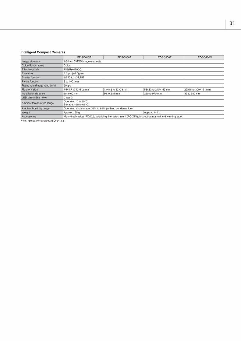
FZ-SQ010F FZ-SQ050F FZ-SQ100F FZ-SQ100N
Image elements 1/3-inch CMOS image elements
Color/Monochrome Color
Effective pixels 752(H)×480(V)
Pixel size 6.0(μm)×6.0(μm)
Shutter function 1/250 to 1/32,258
Partial function 8 to 480 lines
Frame rate (image read time) 60 fps
Field of vision 7.5×4.7 to 13×8.2 mm 13×8.2 to 53×33 mm 53×33 to 240×153 mm 29×18 to 300×191 mm
Installation distance 38 to 60 mm 56 to 215 mm 220 to 970 mm 32 to 380 mm
LED class (See note) Class 2
Ambient temperature range Operating: 0 to 50°CStorage: −25 to 65°C
Ambient humidity range Operating and storage: 35% to 85% (with no condensation)
Weight Approx. 150 g Approx. 140 g
Accessories Mounting bracket (FQ-XL), polarizing filter attachment (FQ-XF1), instruction manual and warning label
Intelligent Compact Cameras
Note : Applicable standards: IEC62471-2
31

LCD Monitor
Cable Extension Unit
Long-distance Camera Cables
Parallel Cable
FZ-M08
Size 8.4 inches
Type Liquid crystal color TFT
Resolution 1,024 × 768 dots
Input signal Analog RGB video input, 1 channel
Power supply voltage 21.6 to 26.4 VDC
Current consumption Approx. 0.7 A max.
Ambient temperature range Operating: 0 to 50°C; Storage: −25 to 65°C (with no icing or condensation)
Ambient humidity range Operating and storage: 35 to 85% (with no condensation)
Weight Approx. 1.2 kg
Accessories Instruction Sheet and 4 mounting brackets
FZ-VS3 (2m) FZ-VSB3 (2m) FZ-VSL3 (2m) FZ-VSLB3 (2m)
Type Standard Bend resistant Right-angle Bend resistant Right-angle
Shock resistiveness (durability) 10 to 150 Hz single amplitude 0.15 mm 3 directions, 8 strokes, 4 times
Ambient temperature range Operation and storage: 0 to 65°C (with no icing or condensation)
Ambient humidity range Operation and storage: 40 to 70%RH (with no condensation)
Ambient atmosphere No corrosive gases
Material Cable sheath, connector: PVC
Minimum bending radius 69 mm 69 mm 69 mm 69 mm
Weight approx. 170 g approx. 180 g approx. 170 g approx. 180 g
FZ-VM
Vibration resistiveness 10 to 150Hz single amplitude 0.15 mm 3 directions, 8 strokes, 4 times
Ambient temperature range Operation: 0 to 50°C; Storage: −20 to +65°C (with no icing or condensation)
Ambient humidity range Operation and storage: 35 to 85%RH (with no condensation)
Ambient atmosphere No corrosive gases
Material Cable sheath: heat-resistant PVC Connector: PVC
Minimum bending radius 75 mm
Weight approx. 170 g
FZ-VSJ
Power supply voltage (See note 1.) 11.5 to 13.5 VDC
Current consumption (See note 2.) 1.5 A max.
Ambient temperature range Operating: 0 to 50°C; Storage: −25 to 65°C (with no icing or condensation)
Ambient humidity range Operating and storage: 35 to 85% (with no condensation)
Maximum Units connectable 2 Units per Camera
Weight Approx. 240 g
Accessories Instruction Sheet and 4 mounting screws
Note 1: A 12-VDC power supply must be provided to the Cable Extension Unit when connecting the Intelligent Compact Camera, the Strobe Controller, or the Lighting Controller.
2: The current consumption shows when connecting the Cable Extension Unit to an external power supply.
FZ-VS4 (15m) FZ-VSL4 (15m)
Type Standard Right-angle
Shock resistiveness (durability) 10 to 150 Hz single amplitude 0.15 mm 3 directions, 8 strokes, 4 times
Ambient temperature range Operation and storage: 0 to 65°C (with no icing or condensation)
Ambient humidity range Operation and storage: 40 to 70%RH (with no condensation)
Ambient atmosphere No corrosive gases
Material Cable sheath, connector: PVC
Minimum bending radius 78 mm
Weight approx. 1400 g
FZ-VP FZ-VPX
Vibration resistiveness 10 to 150 Hz single amplitude 0.15 mm 3 directions, 8 strokes, 4 times
Ambient temperature range Operation: 0 to 50°C; Storage: −20 to 65°C (with no icing or condensation)
Ambient humidity range Operation and storage: 35 to 85%RH (with no condensation)
Ambient atmosphere No corrosive gases
Material Cable sheath: heat-resistant PVC Connector: resin
Minimum bending radius 75 mm
Weight approx. 160 g approx. 180 g
Camera Cables
Monitor Cable
32
R a t i n g s a n d S p e c i f i c a t i o n s ( L C D M o n i t o r , C a b l e )

33
Type of camera Model Resolution
FZ4 series
Quad Processing High-speed Controllers
FZ4-11
High-speed Controllers FZ4-7
Standard Controllers FZ4-6
Lite Controllers FZ4-L35
Digital cameras
FZ-SC 300,000 Pixels Yes Yes Yes Yes
FZ-S 300,000 Pixels Yes Yes Yes Yes
FZ-SC2M 2 million pixels Yes Yes Yes Yes
FZ-S2M 2 million pixels Yes Yes Yes Yes
High-speed cameras
FZ-SHC 300,000 Pixels Yes Yes Yes Yes
FZ-SH 300,000 Pixels Yes Yes Yes Yes
Small digital cameras
FZ-SFC 300,000 Pixels Yes Yes Yes Yes
FZ-SF 300,000 Pixels Yes Yes Yes Yes
FZ-SPC 300,000 Pixels Yes Yes Yes Yes
FZ-SP 300,000 Pixels Yes Yes Yes Yes
Intelligent compact cameras
FZ-SQ010F 360,000 Pixels Yes Yes Yes Yes
FZ-SQ050F 360,000 Pixels Yes Yes Yes Yes
FZ-SQ100F 360,000 Pixels Yes Yes Yes Yes
FZ-SQ100N 360,000 Pixels Yes Yes Yes Yes
Type of camera Model Cable length
High-speedcameras
Digital cameras Small digital cameras Intelligent
compact cameras300,000-pixel 2 million-pixel 5 million-pixel Pen type / flat type
Camera CablesRight-angle camera cables
FZ-VS3FZ-VSL3
2m Yes Yes Yes Yes Yes Yes
3m Yes Yes Yes Yes Yes Yes
5m Yes Yes Yes Yes Yes Yes
10m Yes Yes Yes No Yes Yes
Bend resistant camera cablesBend resistant right-angle camera cables
FZ-VSB3FZ-VSLB3
2m Yes Yes Yes Yes Yes Yes
3m Yes Yes Yes Yes Yes Yes
5m Yes Yes Yes Yes Yes Yes
10m Yes Yes Yes No Yes Yes
Long-distance camera cableLong-distance right-angle camera cable
FZ-VS4FZ-VSL4 15m Yes Yes Yes No Yes Yes
Camera Connection Table
Cameras / Cables Connection Table
C o n n e c t i o n Ta b l e

P r o c e s s i n g I t e m s
*1. Bar Codes that can be read : JAN/EAN/UPC (including add-on codes), Code 39, Codabar (NW-7), ITF (Interleaved 2 of 5), Code 93, Code 128, GS1-128, GS1 DataBar (RSS-14 / RSS Limited / RSS Expanded), Pharmacode
*2. 2D Codes that can be read : Data Matrix (ECC200), QR Code
* The items in red are High Grade processing items.
34
Group Icon Processing ItemCorresponding Page in the Catalog
Inspections / Measurement
Search Used to identify the shapes and calculate the position of measurement objects.
Flexible Search
Recognizing the shapes of workpieces with variation and detecting their positions. P20
Sensitive Search
Search a small difference by dividing the search model in detail, and calculating the correlation. P20
ECM Search
Used to search the similar part of model form input image.Detect the evaluation value and position.
Ec Circle Search
Extract circles using "round " shape information and get position, radius and quantity in high preciseness.
Shape Search+
Used to Search the similar part of models from input image.Detect the evaluation value and position.
Shape Search
Used to search the similar part of model from input image regardless of environmental changes. Detect the evaluation value and position.
P6
Classification Used when various kinds of products on the assembly line need to be sorted and identified.
Edge Position
Measure position of measurement objects according to the color change in measurement area.
Edge PitchDetect edges by color change in measurement area. Used for calculating number of pins of IC and connectors.
Scan Edge Position
Measure peak/bottom edge position of workpieces according to the color change in separated measurement area.
Scan Edge Width
Measure max/min/average width of workpieces according to the color change in separated measurement area.
Circular Scan Edge Position
Measure center axis, diameter and radius of circular workpieces. P20
Circular Scan Edge Width
Measure center axis, width and thickness of ring workpieces. P20
Color Data Used for detecting presence and mixed varieties of products by using color average and deviation.
Gravity and Area
Used to measure area, center of gravity of workpices by extracting the color to be measured.
Labeling Used to measure number, area and gravity of workpieces by extracting registered color.
Label DataSelecting one region of extracted Labeling, and get that measurement. Area and Gravity position can be got and judged.
Labeling+ Extract objects of registered color, and measure many features such as number and circularity.
DefectUsed for appearance measurement of plain-color measurement objects such as defects, stains and burrs.
PreciseDefect Check the defect on the object. Parameters for extraction defect can be set precisely. P21
Fine Matching
Difference can be detected by overlapping and comparing(matching) registered fine images with input images.
P21
Character Inspection
Recognize character according correlation search with model image registered in [Model Dictionary].
Date Verification
Reading character string is verified with internal date.
Model Dictionary
Register character pattern as dictionary. The pattern is used in [Character Inspection].
Barcode+ *1
Recognize barcode, verify and output decoded characters.
2DCode *2 Recognize 2D code and display where the code quality is poor. P21
2DCode+ *2
Recognize 2D code, verify and output decoded characters.
Circle Angle
Used for calculating angle of inclination of circular measurement objects.
Image Capturing
Camera Image Input
To input images from cameras. And set up the conditions to input images from cameras.
Camera Image InputHDR
Create high-dynamic range images by acquiring several images with different conditions. P19
CameraImage Input HDR Lite
HDR function for FZ-SQ Intelligent Compact Cameras.
Camera Switching
To switch the cameras used for measurement. Not input images from cameras again.
Measurement Image Switching
To switch the images used for measurement. Not input images from camera again.
Correcting images
Position Compensation
Used when positions are differed. Correct measurement is performed by correcting position of input images.
Trapezoidal Correction+ Rectify the trapezoidal deformed image. P12
Filtering Used for processing images input from cameras in order to make them easier to be measured.
Group Icon Processing ItemCorresponding Page in the Catalog
Correcting images
Backgrond Suppression
To enhance contrast of images by extracting color in specified brightness.
Brightness Correct Filter
Track brightness change of entire screen and remove gradual brightness change such as uneven brightness.
P15
Color Gray Filter
Color image is converted into monochrome images to emphasize specific color.
Extract Color Filter
Convert color image to color extracted image or binary image.
Anti Color Shading
To remove the irregular color/pattern by uniformizing max.2 specified colors.
Stripes Removal Filter+
Remove the background pattern of vertical, horizontal and cross stripes.
Stripes Removal Filter
Remove the background pattern of vertical, horizontal and diagonal stripes. P18
Halation Cut+ Remove halation from input image.
Panorama+ Combine multiple image to create one big image.
Polar Transformation
Rectify the image by polar transformation. Useful for OCR or pattern inspection printed on circle.
Assisting inspections / measurement
CalculationUsed when using the judge results and measured values of ProcItem which are registered in processing units.
Line Regression
Used for calculating regression line from plural measurement coodinate.
Circle Regression
Used for calculating regression circle from plural measurement coordinate.
Calibration+ Transform (X,Y) position to the real coodinate system.
Precise Calibration
Used for calibration corresponding to trapezoidal distortion and lens distortion. P18
User DataUsed for setting of the data that can be used as common constants and variables in scene group data.
Set Unit Data
Used to change the ProcItem data (setting parameters,etc.) that has been set up in a scene.
Get Unit Data
Used to get one data (measured results, setting parameters,etc.) of ProcItem that has been set up in a scene.
Set Unit Figure
Used for re-setting the figure data (model, measurement area ) registered in an unit.
Get Unit Figure
Used for get the figure data (model, measurement area ) registered in an unit.
Trend Monitor
Used for displaying the information about results on the monitor, facilitating to avoid NG and analyze causes.
Image Logging
Used for saving the measurement images to the memory and USB memory.
Image Conversion Logging
Used for saving the measurement images in JPEG and BMP format. P15
Data Logging
Used for saving the measurement data to the memory and USB memory.
Elapsed Time
Used for calculating the elapsed time since the measurement trigger input.
Wait Processing is stopped only at the set time. The standby time is set by the unit of [ms].
Focus Focus setting is supported. P19
Iris Focus and aperture setting is supported. P19
Branching processing
Conditional Branch
Used where more than two kinds of products on the production line need to detected separately.
End This ProcItem must be set up as the last processing unit of a branch.
DI BranchSame as ProcItem "Branch". But you can change the targets of conditional branching via external inputs.
Outputting results
Data Output
Used when you need to output data to the external devices such as PLC or PC via serial ports.
P19
Parallel Data Output
Used when you need to output data to the external devices such as PLC or PC via parallel ports.
Parallel Judgement Output
Used when you need to output judgement results to the external devices such as PLC or PC via parallel ports.
Fieldbus Data Output
Outputs data to an external device, such as a Programmable Controller, through a fieldbus interface.
Displaying results on the monitor
Result Display
Used for displaying the texts or the figures in the camera image .
Display Image File Display selected image file.
Display Last NG Image
Display the last NG images. P19

35
E x t e r n a l D i m e n s i o n s ( U n i t : m m )
FZ4-series Controllers
LCD-integrated type
Box-type
FZ4-H110 /-H110 -10FZ4-110 /-110 -10FZ4-H70 /-H70 -10FZ4-70 /-70 -10FZ4-H60 /-H60 -10FZ4-60 /-60 -10
FZ4-H115 /-H115 -10FZ4-115 /-115 -10FZ4-H75 /-H75 -10FZ4-75 /-75 -10FZ4-H65 /-H65 -10FZ4-65 /-65 -10
FZ4-L35 /-L35 -10
246
296
130
110
7
6
68
Four, M3 mounting holes witha depth of 6 mm
(7)
(6)
+-
(28.4) 10
33(1
63.5
)
104
20
120 120
20120 120
308
260
The size of the 2-cameratype is 83.
12.8
165
90
190
8
1112
6
17 80
33
(6.8) 11.5
80 17
1112
6
(15.
45)
(68) (68)
100
64
26
Four, 20 dia.
13 1854
(39)
Four, M4mounting holeswith a depth of 6 mm
Four, M4mounting holeswith a depth of6 mm
Four, M4mounting holeswith a depth of 6 mm
The 2-camera type has only twocamera connectors on its right side.
The 2-camera type has only twocamera connectors on its right side.
182.3
8019
712

Cameras
36
(57)11 38
(94.
8)
44
Mounting Bracket
1/4-20UNCDepth: 6
4-M4Depth: 6
46
45
67
Opticalaxis
8
94.
832 20
PolarizingFilter Attachment
20
1
20±0.1
Two, 4.5 dia.
Mounting Hole Dimensions
Tightening torque: 1.2 N·m
3842
(25)
1
PolarizingFilter Attachment
(49)3 38
(94.
8)
44
Mounting Bracket
1/4-20UNCDepth: 6
4-M4Depth: 6
46
45
67
Opticalaxis
8
94.
832 20
20
20±0.1
Two, 4.5 dia.
Mounting Hole Dimensions
Tightening torque: 1.2 N·m
3842
(25)
8
17
16.9
34
26
Four-4.3 dia.
13.5
3
3.4
26
17
M10
.5
3
22
124.
55.
510
3000
43
3 dia.
16 pin round connector
12.5 dia.
9.2(From ccd surface)
Two-4.3 dia.
9.5 16
44
12.7
7.5 20
9.6
33
11.5
3000
431612
99
M10
.5
612
9.2(From ccd surface)
3 di
a.
Eight, M1.7 mounting holes with a depth of 1.5 mm
Four, M1.7 mounting holes with a depth of 1.5 mm
Two, M3 mounting holes with a depth of 4 mm
12.5
dia
.
16 pin round connector
Three, M2 mounting holes with a depth of 3.0 mm
Two, M4 mounting holes with a depth of 5.5 mm
Three, M2 mounting holes with a depth of 3.0 mm
1/4” 20UNC with a depth of 5.5 mm
11 22
(43.8)
28
24
36.5 (6.5)
5.4
5.4
(8.8 dia.)
11
7
7 9.5 9.52 33.5
22
121228
6.5
(8.5
)
(20.
7)
Three, M2 mounting holes with a depth of 3.0 mm
Three, M2 mounting holes with a depth of 3.0mm (both sides)
Two, M4 mounting holes with a depth of 5.5 mm
1/4” 20UNC with a depth of 5.5 mm
10.5
40 (7.3)
12
14.5 22
5.5 33.510.5 9.5 9.5
6.5
28
28
24
12
14.5 22
(19.
4)
(5.4)
(7.9
)20.5
1"-32UN-2A (C mount)
10.5
14.5 29
46.5
20.512
(7.3)
10.59.5
9.5
5.5 40.5
14.5
12
29
28
286.
5
241"-32UN-2A(C MOUNT)
Three, M2 mounting holes with a depth of 3.0 mm
Three, M2 mounting holes with a depth of 3.0mm (both sides)
Two, M4 mounting holes with a depth of 5.5 mm
1/4" 20UNC with a depth of 5.5 mm
(5.4)
(19.
4)
(7.9
)
Two, M4 mounting holes with a depth of 5.5 mm
14.5
(1)
17.510.5
15.5
8.3
9.59.5
Four M4 mounting holes with a depth of 4 mm (4 commonness)
Four-R3
7 1“-32UNF(C mount)
36 dia.
1/4” 20UNC with a depth of 5.5 mm
40.9
30.2
25 16.8
48.2
30 d
ia.
35
34
35
17.5
Digital Cameras
Small digital cameras
High-speed Camera
300,000-pixel camera
Camera head
Intelligent Compact Cameras (Dimensional drawings are provided here only for the products that have undergone design changes as of Dec. 2012.)
Camera amplifier
FZ-SFZ-SC
2 million-pixel cameraFZ-S2MFZ-SC2M
FZ-SHFZ-SHC
Flat camera
FZ-SFFZ-SFC
Narrow view / Standard
FZ-SQ010FFZ-SQ050F
Note 1: The mounting brackets can be connected to either side. Note 1: The mounting brackets can be connected to either side.
Wide View
FZ-SQ100F (long-distance)FZ-SQ100N (short-distance)
Pen-shaped camera
FZ-SPFZ-SPC
Can be used for both flat cameras and pen-shaped cameras

7.5
dia.
(See Note 2.)26-pin square connector
L (See Note 1.)(100)(40)
(25)
(30)(9)
(11)
26-pin rectangular connector
L (See Note 3.)(100)
(See Note 2.)
7.8
dia.
(42)(40)
(24)
(12)
(See Note 2.)
L (See Note 1.)(100)
8.0
dia.
26-pinrectangular connector
(9)
(11)
(25)
(40)(30)
26-pin square connector
L (See Note 3.)
26-pin square connector
(See Note 2.)
(25)
(100)
(24)
(42)(40)
(10)
(34)
7.8
dia.
(See Note 2.)
L (See Note 1.)
7.5
dia.
26-pinrectangular connector
26-pinrectangular connector
(25)
(18)
(11)
(34)(40) (100)
(10)
(30)(2
5)(9)
(See Note 2.)
L (See Note 1.)
8.0
dia.
26-pinrectangular connector
26-pinrectangular connector
(9)(100)
(30)(34)
(10)
(40)
(25)
(25)
(18)
(11)
50-pin square connector
(100)(30)(10)
35
35.4
L (See Note 1.)200±1050±10
6.9
dia.
50-pin square connector
L (See Note 1.)(100)
35.4
68.1
6.9
dia.
35 35
50-pin square connector
810
L (See Note 1.)
(32.5)(32.5)
(39)
(15)
Two, 15-pin rectangular connector
4.5
dia.
(14
dia.
)
(33.
5)
Cables
Camera Cables
Parallel Cable
Monitor Cable
Camera Cable
Long-distance Right-angle Camera Cable Long-distance Camera Cable
Right-angle Camera Cable Bend resistant Right-angle Camera Cable
Bend resistant Camera CableFZ-VS3
FZ-VP FZ-VPX
FZ-VM
FZ-VSL4FZ-VS4
FZ-VSL3 FZ-VSLB3
FZ-VSB3
Note 1: Cable is available in 2m/3m/5m/10m. 2: Each camera cables has polarity. Please ensure that the name plate side of the cable is connected to the controller. 3: Cable is available in 15m.
Note 1: cable is available in 2m/5m. Note 1: cable is available in 2m/5m.
Note 1: Cable is available in 2m/5m.
37

LCD Monitor
Lens for Small Camera
Camera Cable Extension Unit Extension Tubes for Small Camera
FZ-M08
FZ-LES Series
FZ-VSJ FZ-LESR
Lenses Model Focal length Brightness Maximum outside diameter Overall length
FZ-LES3 3 mm F2.0 12 dia. 16.4 mm
FZ-LES6 6 mm F2.0 12 dia. 19.7 mm
FZ-LES16 16 mm F3.4 12 dia. 23.1 mm
FZ-LES30 30 mm F3.4 12 dia. 25.5 mm
(103.5)
220
(130)
(90)
75(31.5)40
(172)
230
(85.
5)
(38) (1
2.5)
(129
.4)
(173
.4)
(185
)
171 75
26
161
(6)
Mountable plate thickness: 1.6 to 5.0 mm
Four, M4
Camera Cable Connector (Controller side) Power terminal
Camera Cable Connector(Camera side)
POWER LED Indicator
Four, 3.4 dia.
83
65
60
3.2 3.2
75
54
28
4
149
9.1
14.9
159
9.1
93.8
4.85
4.85
3 5
M10
.5
3 10
M10
.5
3 15
M10
.512
dia
.
Extension tubes5mm
Extension tubes10mm
12 d
ia.
12 d
ia.
Extension tubes15mm
L
4
Diaphragmadjustment knob
Diaphragm look screw (M1.4)
12 d
ia.
38

39
O p t i c a l C h a r t
2 million-pixel digital camera FZ-S 2M
10 100 1,0003
100
1,000
10,000
30
Field of vision (mm)
t15t25
t30
t50t40
t20
t10t5
t0
t50t40
t30t25
t20t15 t10
t5
t0
t0
t5
t10t15t20t25t30t40
t0
t5
t10t15t20t25t30
t0
t2
t5
t10t15
t0
t2
t5
t0
t1
t2
t0
t0.5
t1
t0
t0.5
3Z4S-LE
Cam
era
dist
ance
(m
m)
SV-10028H
SV-7525H
SV-5014H
SV-3514H
SV-2514H
SV-1614H
SV-1214HSV-0814H
SV-0614H
300,000-pixel High-speed camera FZ-SH , and Digital camera FZ-S
30
100
1,000
10,000
2 10 100 1,000
SV-5018VSV-3518V
SV-10035VSV-7527V
SV-2514VSV-1614VSV-1214VSV-0813VSV-0614VSV-04514VSV-03514V
3Z4S-LE
Cam
era
dist
ance
(m
m)
Field of vision (mm)
t0
t5
t10t15t20t25
t40t30
t50
t50
t0
t5
t10t15t20t25
t40t2
t5
t10t15t20t25t30t40
t1
t5
t10t15t20t25
t1
t2
t5
t10
t15
t20
t0.5
t1
t2
t5
t0.5
t1
t2
t0.5
t1 t0.5
t1
t1t0.5 t0.5
t30
t0
t0
t0
t0
t0
t0t0
t0
t0

40
Note 1: The vertical axis represents WD, not installation distance.
Meaning of Optical ChartThe X axis of the optical chart shows the field of vision (mm) (See Note 1.),and the Y axis of the optical chart shows the camera installation distance (mm) (See Note 2.).
Extension Tube thickness: t (mm)
Camera
Lens
Field of visionY
X
Camera distance (mm) WD
(mm)
Field of vision (mm)
Note 1: The lengths of the fields of vision given in the optical charts are the lengths of the Y axis. 2: The vertical axis represents WD for small cameras.
300,000-pixel small digital cameras FZ-SF , FZ-SP
1
t20
t20
t15
t25
t15
t10
t30t40t45t50
t55t60
t35
t10
t5
t5t0
t0
t0
t0
10 100 100010
100
1000
10000FZ-LES30
FZ-LES16
FZ-LES6
FZ-LES3
Field of vision (mm)
(mm)WD [Note1]

41
Intelligent Compact Cameras
3860
7.5
13
8.2
0
4.7
Field of vision
to
Narrow View
FZ-SQ010F
056
215
13
53
8.2
33
Field of vision
to
Standard
FZ-SQ050F
0220
97053
240
33
153
Field of vision
to
Wide View (Long-distance)
FZ-SQ100F
032
38029
300
18
191Field of vision
to
Wide View (Short-distance)
FZ-SQ100N
(Unit: mm)

In the interest of product improvement, specifications are subject to change without notice.
0812 (1211)
© OMRON Corporation 2011 All Rights Reserved.
One Commerce Drive Schaumburg,IL 60173-5302 U.S.A.Tel: (1) 847-843-7900/Fax: (1) 847-843-7787
Regional Headquarters
Wegalaan 67-69-2132 JD HoofddorpThe NetherlandsTel: (31)2356-81-300/Fax: (31)2356-81-388
No. 438A Alexandra Road # 05-05/08 (Lobby 2), Alexandra Technopark, Singapore 119967Tel: (65) 6835-3011/Fax: (65) 6835-2711
Room 2211, Bank of China Tower, 200 Yin Cheng Zhong Road, PuDong New Area, Shanghai, 200120, ChinaTel: (86) 21-5037-2222/Fax: (86) 21-5037-2200
CSM_14_4_0118