vision-based control of an inverted pendulum using cascaded
TRANSCRIPT

IMTC 2008 – IEEE Instrumentation and MeasurementTechnology ConferenceVictoria, Canada, May 12–15, 2008
Vision-Based Control of an Inverted Pendulum using Cascaded Particle Filters
Manuel Stuflesser and Markus BrandnerInstitute of Electrical Measurement and Measurement Signal Processing,
Graz University of Technology,Kopernikusgasse 24/IV, A8010 Graz, Austria
E–mail: [email protected]
Abstract – The inverted pendulum represents an example of a non-linear and unstable dynamic system whose properties and related con-trol strategies have been studied extensively in the control literature.A basic setup consists of a translation device – the cart – and a rotat-ing boom – the pendulum – which is balanced in its upright position.The control algorithm uses the position of the cart and the rotationangle of the pendulum as input measurements provided by differentsensors. While contacting sensor principles such as angle encodershave been used in different demonstrators, we present a purely vision-based tracking system. In combination with state of the art controlalgorithms our system is able to swing-up and balance the pendu-lum. The presented setup is non-contacting and does not require spe-cific visual markers on any part of the pendulum. We use off-the-shelfcomponents to realise the monocular tracking system. Experimentalresults show that our system is able to robustly control the invertedpendulum in real-time on a standard desktop PC.
Keywords – Tracking, Optical Metrology, Visual Feedback, ParticleFilter
I. INTRODUCTION
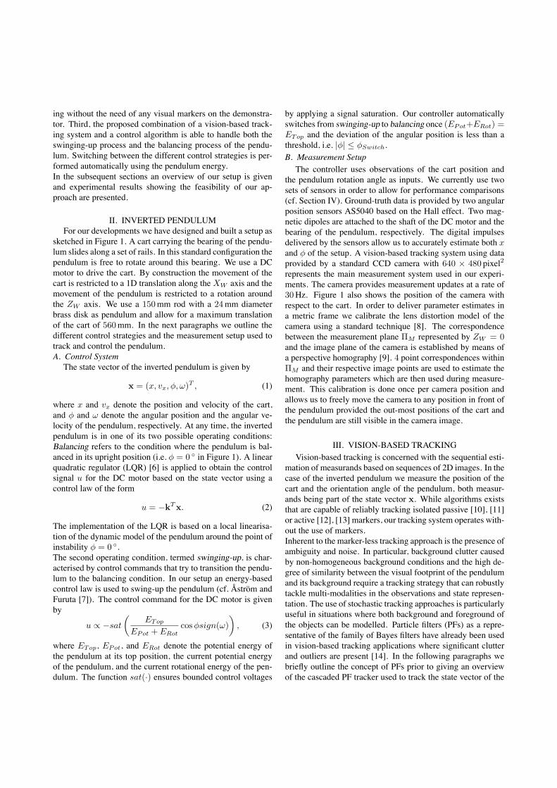
The basic geometry of the inverted pendulum is shown inFigure 1. A control algorithm is used to drive the cart in or-der to balance the pendulum in its upright position. Due to itsdynamic properties the inverted pendulum has become one ofthe classical examples in the literature used to develop and val-idate control algorithms for non-linear and unstable dynamicsystems [1].From a control perspective the position of the cart and the de-viation of the pendulum from its upright position are relevantmeasurands in order to control the pendulum and to ensure thatthe cart remains within its allowed range of positions. Tradi-tional sensors such as rotation angle encoders are frequentlyapplied in this context [2]. These sensors provide robust mea-surement data but require mechanical coupling to the pendu-lum and electrical connections to the controller. An appealingproperty of vision-based measurement systems is the lack offeedback to the measurand. Hence, the dynamics of the in-verted pendulum are not influenced by additional mass (e.g. themass of a sensor) and friction (e.g. sensor cabling). Only fewworks target the vision-based control of an inverted pendulum.
Fig. 1. Sketch of inverted pendulum. The aim of the experiment is to balancethe pendulum in its upright position (φ = 0 ) by means of providing control
signals to the DC motor which in turn drives the supporting cart.
Wenzel et al. [3] present a demonstrator using dedicated mark-ers that are detected in a sequence of camera images using pat-tern matching algorithms. The proposed structure only coversthe control of the balancing pendulum but does not include theautomatic swinging-up of the pendulum. Vision feedback isalso used by Magana and Holzapfel [4] in a fuzzy logic con-trol scheme. The algorithm used to deduce the position of thependulum given a sequence of images puts severe restrictionson the positioning of the camera with respect to the pendulum.Martinez and Becerra [5] use optical flow as primary source ofinformation to train and consequently apply an adaptive con-troller for the inverted pendulum task. This work is based onsimulations in a virtual reality environment.This paper presents a vision-based feedback system which
extends the state of the art by providing the following features:First, the system properly handles full perspective distortionsof the camera images. Thus, the camera can be placed any-where in front of the demonstrator – visibility of the pendulumprovided. A simple on-site calibration step is required to esti-mate the necessary parameters of this transformation. Second,a cascaded set of particle filters is used to track the cart and thependulum. This particular combination enables robust track-
ing without the need of any visual markers on the demonstra-tor. Third, the proposed combination of a vision-based track-ing system and a control algorithm is able to handle both theswinging-up process and the balancing process of the pendu-lum. Switching between the different control strategies is per-formed automatically using the pendulum energy.In the subsequent sections an overview of our setup is givenand experimental results showing the feasibility of our ap-proach are presented.
II. INVERTED PENDULUMFor our developments we have designed and built a setup as
sketched in Figure 1. A cart carrying the bearing of the pendu-lum slides along a set of rails. In this standard configuration thependulum is free to rotate around this bearing. We use a DCmotor to drive the cart. By construction the movement of thecart is restricted to a 1D translation along theXW axis and themovement of the pendulum is restricted to a rotation aroundthe ZW axis. We use a 150mm rod with a 24mm diameterbrass disk as pendulum and allow for a maximum translationof the cart of 560mm. In the next paragraphs we outline thedifferent control strategies and the measurement setup used totrack and control the pendulum.A. Control SystemThe state vector of the inverted pendulum is given by
x = (x, vx,φ, ω)T , (1)
where x and vx denote the position and velocity of the cart,and φ and ω denote the angular position and the angular ve-locity of the pendulum, respectively. At any time, the invertedpendulum is in one of its two possible operating conditions:Balancing refers to the condition where the pendulum is bal-anced in its upright position (i.e. φ = 0 in Figure 1). A linearquadratic regulator (LQR) [6] is applied to obtain the controlsignal u for the DC motor based on the state vector using acontrol law of the form
u = −kT x. (2)
The implementation of the LQR is based on a local linearisa-tion of the dynamic model of the pendulum around the point ofinstability φ = 0 .The second operating condition, termed swinging-up, is char-acterised by control commands that try to transition the pendu-lum to the balancing condition. In our setup an energy-basedcontrol law is used to swing-up the pendulum (cf. Astrom andFuruta [7]). The control command for the DC motor is givenby
u ∝ −sat
(ETop
EPot + ERotcos φsign(ω)
), (3)
where ETop, EPot, and ERot denote the potential energy ofthe pendulum at its top position, the current potential energyof the pendulum, and the current rotational energy of the pen-dulum. The function sat(·) ensures bounded control voltages
by applying a signal saturation. Our controller automaticallyswitches from swinging-up to balancing once (EPot+ERot) =ETop and the deviation of the angular position is less than athreshold, i.e. |φ| ≤ φSwitch.B. Measurement SetupThe controller uses observations of the cart position and
the pendulum rotation angle as inputs. We currently use twosets of sensors in order to allow for performance comparisons(cf. Section IV). Ground-truth data is provided by two angularposition sensors AS5040 based on the Hall effect. Two mag-netic dipoles are attached to the shaft of the DC motor and thebearing of the pendulum, respectively. The digital impulsesdelivered by the sensors allow us to accurately estimate both xand φ of the setup. A vision-based tracking system using dataprovided by a standard CCD camera with 640 × 480 pixel2represents the main measurement system used in our experi-ments. The camera provides measurement updates at a rate of30Hz. Figure 1 also shows the position of the camera withrespect to the cart. In order to deliver parameter estimates ina metric frame we calibrate the lens distortion model of thecamera using a standard technique [8]. The correspondencebetween the measurement plane ΠM represented by ZW = 0and the image plane of the camera is established by means ofa perspective homography [9]. 4 point correspondences withinΠM and their respective image points are used to estimate thehomography parameters which are then used during measure-ment. This calibration is done once per camera position andallows us to freely move the camera to any position in front ofthe pendulum provided the out-most positions of the cart andthe pendulum are still visible in the camera image.
III. VISION-BASED TRACKINGVision-based tracking is concerned with the sequential esti-
mation of measurands based on sequences of 2D images. In thecase of the inverted pendulum we measure the position of thecart and the orientation angle of the pendulum, both measur-ands being part of the state vector x. While algorithms existsthat are capable of reliably tracking isolated passive [10], [11]or active [12], [13] markers, our tracking system operates with-out the use of markers.Inherent to the marker-less tracking approach is the presence ofambiguity and noise. In particular, background clutter causedby non-homogeneous background conditions and the high de-gree of similarity between the visual footprint of the pendulumand its background require a tracking strategy that can robustlytackle multi-modalities in the observations and state represen-tation. The use of stochastic tracking approaches is particularlyuseful in situations where both background and foreground ofthe objects can be modelled. Particle filters (PFs) as a repre-sentative of the family of Bayes filters have already been usedin vision-based tracking applications where significant clutterand outliers are present [14]. In the following paragraphs webriefly outline the concept of PFs prior to giving an overviewof the cascaded PF tracker used to track the state vector of the
inverted pendulum. A more general introduction to the topicof PF can be found in Arulampalam et al. [15].
A. Particle FilteringBayesian filters are used to estimate the inner state of a dy-
namic system by means of repeated observations. In general,the dynamic model of the system is given by
xk = f(xk−1,vk), (4)
where f(·) represents a vector-valued function describing thestate transitions and vk denotes a noise component. A prob-abilistic representation of the state vector is used. Thus, thestate vector xk at time step k is fully described by its probabil-ity density function (pdf) p(xk). Measurements are related tothe state vector by
zk = h(xk,wk), (5)
where again h(·) is a vector-valued function and wk rep-resents the measurement noise. Using the symbol Zk =z1, z2, . . . zk to denote the history of all measurements ob-tained up to time k we can now formulate the Bayesian filterproblem as the estimation of xk knowing Zk.In an iterative formulation the Bayes filter alternately performsprediction and measurement steps. The prediction step exe-cutes the state transition from time step k − 1 to time stepk. In other words, using conditional densities, the transitionfrom p(xk−1|Zk−1) to p(xk|Zk−1). For first order Markovprocesses the current state depends only on its immediate pre-decessor so that the state transition in Equation 4 is fully char-acterised by the conditional density p(xk|xk−1). Applying theChapman-Kolmogorov equation we obtain the prior state den-sity – or a priori density – by
p(xk|Zk−1) =∫
Ωp(xk|xk−1)p(xk−1|Zk−1)dxk−1. (6)
Prior density in this context refers to the fact that the state den-sity is expressed prior to the measurement step which is de-scribed next. Measurements are incorporated into the currentestimate using Bayes law. The posterior state density is givenby
p(xk|Zk) =p(zk|xk) · p(xk|Zk−1)
p(Zk), (7)
where p(zk|xk) denotes the probabilistic formulation of themeasurement process (cf. Equation 5). For Gaussian densitiesboth the prediction step in Equation 6 and the measurement up-date in Equation 7 can be solved analytically leading to the wellknown Kalman filter algorithm [16]. However, in situationswhere densities deviate from the Gaussian case (e.g. multi-modal state densities), the prediction and measurement stepscan only be solved numerically. Particle filters (PFs) approxi-mate state pdfs by means of stochastic samples. Thus, the pdfp(xk) is approximated by
p(xk) ≈ s(m)k ,π(m)
k m = 1, . . . , N, (8)
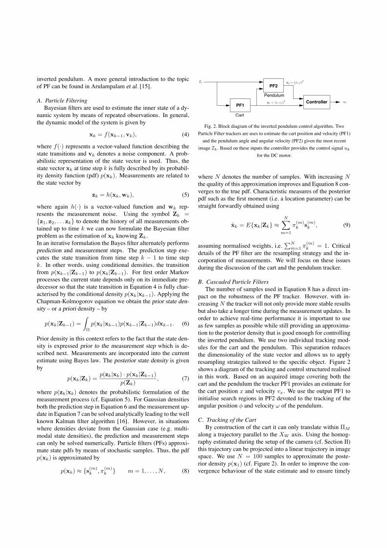
ControllerPF1
PF2
Pendulum
Cart
x2 = (φ, ω)T
x1 = (x, vx)T uk
Ik
Fig. 2. Block diagram of the inverted pendulum control algorithm. TwoParticle Filter trackers are uses to estimate the cart position and velocity (PF1)and the pendulum angle and angular velocity (PF2) given the most recent
image Ik . Based on these inputs the controller provides the control signal uk
for the DC motor.
where N denotes the number of samples. With increasing Nthe quality of this approximation improves and Equation 8 con-verges to the true pdf. Characteristic measures of the posteriorpdf such as the first moment (i.e. a location parameter) can bestraight forwardly obtained using
xk = Exk|Zk ≈N∑
m=1
π(m)k s(m)
k , (9)
assuming normalised weights, i.e.∑N
m=1 π(m)k = 1. Critical
details of the PF filter are the resampling strategy and the in-corporation of measurements. We will focus on these issuesduring the discussion of the cart and the pendulum tracker.
B. Cascaded Particle FiltersThe number of samples used in Equation 8 has a direct im-
pact on the robustness of the PF tracker. However, with in-creasingN the tracker will not only provide more stable resultsbut also take a longer time during the measurement updates. Inorder to achieve real-time performance it is important to useas few samples as possible while still providing an approxima-tion to the posterior density that is good enough for controllingthe inverted pendulum. We use two individual tracking mod-ules for the cart and the pendulum. This separation reducesthe dimensionality of the state vector and allows us to applyresampling strategies tailored to the specific object. Figure 2shows a diagram of the tracking and control structured realisedin this work. Based on an acquired image covering both thecart and the pendulum the tracker PF1 provides an estimate forthe cart position x and velocity vx. We use the output PF1 toinitialise search regions in PF2 devoted to the tracking of theangular position φ and velocity ω of the pendulum.
C. Tracking of the CartBy construction of the cart it can only translate within ΠM
along a trajectory parallel to the XW axis. Using the homog-raphy estimated during the setup of the camera (cf. Section II)this trajectory can be projected into a linear trajectory in imagespace. We use N = 100 samples to approximate the poste-rior density p(x1) (cf. Figure 2). In order to improve the con-vergence behaviour of the state estimate and to ensure timely

recovery of the cart after visual occlusions, 25 % of the sam-ples are obtained in an importance sampling step [14]. Impor-tance sampling tries to sample the state space where the posi-tion of the cart is most likely. As an importance measure thecorrelation of the image pixels along the cart trajectory with atemplate function t(x) is used. We obtain the template by pro-jecting an approximation of the cart’s visual footprint onto theimage plane.Measurement updates focus on the visual contour of the cart.In order to update each individual sample weight we measurethe edge position along L = 16 measurement lines as outlinedin Figure 3a. Each of these measurement lines has a lengthof D pixels in the image domain. Assuming that the gradient-based edge detection of measurement line l results in Rl con-tour candidates zr, we obtain a new sample weight
πk =L∏
l=1
∑Rl
r=11√2πσ
e−(zr−D/2)2
2σ2
e−λD (λD)Rl
Rl!
. (10)
This equation includes a Gaussian measurement model and aPoisson background model. The individual parameters σ andλ depend on the measurement setup and have been identifiedexperimentally. A kernel density estimator [17] is applied todetermine the best estimate of the unknown elements of thestate vector.
D. Tracking of the PendulumSimilar to the cart, the pendulum is tracked using a sepa-
rate PF. During the measurement L = 8 measurement lines asshown in Figure 3b are used. Again a 1D edge detection algo-rithm is applied along each measurement line and the combi-nation of the obtained foreground/background ratios are usedto obtain an update for the weight of the sample as shown inEquation 10. We apply an importance sampling strategy usinga correlation measure evaluated along the possible orientationsof the pendulum. Knowing the centre of the bearing as a resultof PF1 and the geometry of the pendulum the set of possiblepositions of the pendulum describes an ellipse in the imageplane. For the pendulum, too, we useN = 100 samples with aa portion of 25 % as importance samples.
IV. EXPERIMENTSThe presented vision-based tracking system has been im-
plemented on a standard desktop PC (Intel Core2 1.86GHz)running the Linux operating system. Hall sensors used to de-termine the position and the orientation of the pendulum havebeen added for reference purposes. A CPLD logic interfacesthe sensor data to the PC via a general purpose digital I/O in-terface. Figure 4 shows a close-up of the demonstrator.In our experiments the vision-based tracker has provided
state estimates at frame-rate (i.e. 30 fps). This update rate issufficient to balance the pendulum in its upright position in oursetup. The elements of the state vector estimated during a pe-riod of 15 s are shown in Figure 5. In this particular experiment
two aspects of our implementation have been validated: First,the proper switching between the initialisation and the balanc-ing control law is discussed. After launching the applicationthe controller tries to bring the pendulum in the upright posi-tion. At time t ≈ 7.5 s the application automatically switchesfrom the P-control law to the LQR control law. The pendulumis successfully balanced in the upright position until the endof the experiment. The second aspect of this experiment is thecomparison between the Hall sensor readings and the vision-based measurements obtained by PF1 and PF2. The deviationsbetween these signals are shown for x and φ in Figure 5b andd, respectively.The outliers represented by spikes in the deviation measuresare caused by two effects: First, the acquired measurementsignals from the Hall sensors and the vision-based tracker donot correspond to exactly the same time instances due to thelatency introduced by the image acquisition system (camera,firewire bus). Second, we observe a model mismatch betweenthe true object dynamic and the motion model used by the PF.This can not be avoided - in particular during the change be-tween swing motion and constant position of the pendulum.However, the experiments show that the quality of the esti-mated state vector is sufficient to balance the pendulum.We have performed experiments to determine the optimal sizeof the importance sample set. For N = 100 samples used byboth the cart and the pendulum particle filter,NIS = 25 impor-tance samples showed to be a good trade-off between computa-tional complexity and robustness of the resultant tracking algo-rithms. Figure 6 shows the different types of samples (standardresampling, importance sampling, initialisation) and the corre-sponding contour detections superimposed to a single framecaptured by the camera. It is evident that although false posi-tives appear (e.g. at the window in the background on the leftof the image), the true cart and pendulum positions are suc-cessfully tracked.
Fig. 4. Inverted pendulum prototype. The cart, pendulum, and parts of thedriving DC motor are shown on the left. A firewire camera is used to providevisual feedback for the control algorithm. In this prototype both vision-basedtracking and commercially available Hall sensors can be used to measure the
state of the pendulum.

(a) (b)Fig. 3. Measurement models. (a) 16 measurement lines are used to identify and track the cart. (b) 8 radially symmetric measurement lines are used for the
pendulum. In both cases the sample that gave rise to the measurement lines is depicted as blue square.
0 5 10 15!0.2
!0.15
!0.1
!0.05
0
0.05
0.1
0.15
0.2
time / s
x / m
Position SensorCar Tracker
0 5 10 15!0.02
!0.015
!0.01
!0.005
0
0.005
0.01
0.015
0.02De
viatio
n Po
sitio
n / m
time / s(a) (b)
0 5 10 15!4
!3
!2
!1
0
1
2
3
4
time / s
! / r
ad
Angle SensorPendulum Tracker
0 5 10 15!0.15
!0.1
!0.05
0
0.05
0.1
0.15
0.2
Devia
tion
Angl
e / r
ad
time / s(c) (d)
Fig. 5. Measurement results of the vision-based tracking algorithm. (a) Position of the cart measured by the Hall sensor and the particle filter PF1. The deviationsof the PF1 result w.r.t. the Hall sensor are shown in (b). (c) Orientation angle of the pendulum as observed by the Hall sensor and PF2. Again, deviations areshown in (d). The vertical lines at t ≈ 7.5 s in (a) and (c) denote the point where the application switches between swinging-up and balancing of the pendulum.

Fig. 6. Different types of samples (yellow) and the resultant contour detections (blue) superimposed to a camera frame: Standard resampling (+), importancesampling (x), and initialisations (o). Samples used by the cart tracker are distributed horizontally along the cart track while samples used by the pendulum are
distributed along the ellipse centred at the cart representing possible pendulum locations.
V. CONCLUSION
In the present paper we report on the design and imple-mentation of a vision-based system used to control an invertedpendulum. While we employ standard algorithms to obtaina control output for the different operating conditions of thependulum, the novelty of our approach lies in the specific useof a set of cascaded particle filter trackers. Our approach ischaracterised by the absence of any artificial landmarks. Fur-ther, only a simple calibration step is required in order to ob-tain stable tracking results using a monocular camera setup atan arbitrary position in front of the pendulum. Through theuse of a contour-based measurement process, our system onlyrequires a minimum visual contrast between the pendulum orcart and the background. The system performs both initialisa-tion and balancing of the pendulum using automated switchingbetween different control laws. Experimental results using animplementation on a standard PC show that the vision-basedtracking algorithm provides unbiased estimates of the pendu-lum’s state vector and is sufficiently robust to control the pen-dulum.
ACKNOWLEDGEMENTS
This work was supported by the Austrian Science Founda-tion (FWF) under grant No. S9103-N13.
BIBLIOGRAPHY[1] G. F. Franklin, J. D. Powell, and A. Emami-Naeini, Feedback Control of
Dynamic Systems, Number ISBN 0130323934. Prentice Hall, 2002.[2] Z. Lin, A. Saberi, M. Gutmann, and Y. A. Shamash, “Linear controller
for an inverted pendulum having restricted travel: a high-and-low gainapproach,” Automatica, vol. 32, no. 6, pp. 933–937, 1996.
[3] L.Wenzel, N. Vazquez, D. Nair, and R. Jamal, “Computer vision basedinverted pendulum,” in Instrumentation and Measurement TechnoloqyConference, 2000, vol. 3, pp. 1319–1323.
[4] M.E. Magana and F. Holzapfel, “Fuzzy-logic control of an inverted pen-dulum with vision feedback,” in IEEE Transactions on Education, May1998, vol. 41, pp. 165–170.
[5] G. Martinez-Hernandez and V.M. Becerra, “Preliminary results from areal time control system using optical information,” in Systems, Man andCybernetics, October 2004, vol. 6, pp. 5923–5928.
[6] C.-T. Chen, Analog and digital control system design: Transfer-Function, State-Space, and Algebraic Methods, Number ISBN 0-03-094070-2. Saunders College Publishing, 1993.
[7] K.J. Astrom and K. Furuta, “Swinging up a pendulum by energy con-trol,” in Automatica, February 2000, vol. 36, pp. 287–295.
[8] “Caltech Camera Calibration Toolbox for MATLAB,”http://www.vision.caltech.edu (10.11.2007).
[9] R. I. Hartley and A. Zisserman, Multiple View Geometry in ComputerVision, Cambridge University Press, 2nd edition, 2004.
[10] H. Kato, M. Billinghurst, I. Poupyrev, K. Imamaoto, and K. Tachibana,“Virtual object manipulation on a table-top ar environment,” in Proc. ofthe International Symposium on Augmented Reality (ISAR 2000), Mu-nich, Germany, 2000, pp. 111–119.
[11] L. Naimark and E. Foxlin, “Circular data matrix fiducial system and ro-bust image processing for a wearable vision-inertial self-tracker,” Darm-stadt, Germany, 2001.
[12] M. Ribo, A. Pinz, and A. L. Fuhrmann, “A new Optical Tracking Sys-tem for Virtual and Augmented Reality Applications,” in Proc. of IEEEInstrumentation and Measurement Technology Conference, IMTC 2001,Budapest, Hungary, May 2001, vol. 3, pp. 1932–1936.
[13] K. Dorfmuller, “Robust tracking for augmented reality using retroreflec-tive markers,” vol. 23, no. 6, pp. 795–800, December 1999.
[14] M. Isard and A. Blake, “ICondensation: Unifying low-level and high-level tracking in a stochastic framework,” in Proc. of European Confer-ence on Computer Vision (ECCV), 1998.
[15] M. S. Arulampalam, S. Maskell, N. J. Gordon, and T. Clapp, “A tutorialon particle filters for online nonlinear/non-gaussian bayesian tracking,”IEEE Trans. on Signal Processing, vol. 50, no. 2, pp. 174–188, 2002.
[16] R.E. Kalman, “A new approach to linear filtering and prediction prob-lems,” Transactions of the ASME–Journal of Basic Engineering, pp.35–45, March 1960.
[17] C. Chang and R. Ansari, “Kernel particle filter: iterative sampling forefficient visual tracking,” in IEEE International Conference on ImageProcessing (ICIP’03), September 2003, vol. 3, pp. 977–980.