virtual resource management* - computer engineeringmorris/papers/vrm.pdf · 1.5.1 mark hoover 6 ......
TRANSCRIPT

Virtual Resource Management*
(*AKA Server Load Balancing and Non-Server Load Balancing)
Key Technologies, Tricks of the Trade, andApplication Requirements
Version 3.0


Do Not Duplicate 1 Research Report 99001_v3.0
TABLE OF CONTENTS1 INTRODUCTION.............................................................................................................................................41.1 About This Report 4
1.2 What Is Virtual Resource Management? 5
1.3 Who Is Acuitive? 5
1.4 About Our Reports and Subscription Service 6
1.5 About The Authors 61.5.1 Mark Hoover 61.5.2 Dave Logan 7
2 KEY ADVANTAGES OF DEPLOYING VIRTUAL RESOURCE MANAGEMENT .....................................8
3 THE TECHONOMICS OF VRM .....................................................................................................................9
4 THE LIFE OF A LOAD BALANCED SESSION..........................................................................................104.1 The Life of an HTTP Session 10
4.2 Being Told Where to Go: Local VRM 12
5 TECHNOLOGY AND TECHNIQUES: OVERVIEW....................................................................................135.1 Introduction 13
5.2 The Functional Components of a VRM System 145.2.1 VRM “Schedulers” 15
6 SINGLE SITE VRM: FEEDBACK (RESOURCE MONITORING) .............................................................166.1 Introduction 16
6.2 External Monitoring 176.2.1 Device ICMP Pinging (DIP) 176.2.2 TCP Connection Observation (TCO) 176.2.3 TCP Connection Verification (TCV) 186.2.4 Active Content Verification (ACV) 186.2.5 Passive Content Verification (PCV) 206.2.6 Dynamic Application Verification (DAV) 216.2.7 Remote External Probes 21
6.3 Resource-Resident Monitoring 226.3.1 Feedback Interfaces 226.3.2 Using Server-Resident Monitoring 246.3.3 Limitations and Recommendations 24
6.4 Summary of Local Feedback Techniques 25
7 SINGLE SITE POLICIES: SERVER SELECTION .....................................................................................267.1 “Best Available” Server Policies 26
7.1.1 Round Robin Policy 267.1.2 Least Connections Policy 277.1.3 Packet and Byte Rate Policies 277.1.4 Response Time Related Policies 287.1.5 Server Resource Management Policies 297.1.6 Optimizing Potential Target Server Pools 307.1.7 Best Available Server Policies Summary 32
7.2 Persistency Policies 327.2.1 Proxy Firewalls: Ensuring That Persistency Isn’t Too Easy 347.2.2 Core VRM Persistence Feature Options 347.2.3 Addressing “Shopping Cart” Persistency 377.2.4 A Better Way To Handle Some Persistence? Avoid The Problem! 397.2.5 Persistency and URL-Based Scheduling 397.2.6 Persistency Options Summary 40
7.3 Preferential Services 417.3.1 Preferential Services User Discrimination 417.3.2 Preferential Services Targets 427.3.3 Preferential Services Mechanisms 437.3.4 Preferential Services Policies 447.3.5 Overall Analysis 44
7.4 Some Final Thoughts On Policies 45

Do Not Duplicate 2 Research Report 99001_v3.0
8 SINGLE SITE VRM: MECHANISMS...........................................................................................................468.1 Immediate Binding Mechanisms 46
8.1.1 MAC Address Translation (MAT) 478.1.2 MAC Multicast (MAM) 488.1.3 Half Network Address Translation (HNAT) 498.1.4 Full NAT (FNAT) 52
8.2 Delayed Binding Mechanisms 528.2.1 TCP “Diddling” (TCPD) 528.2.2 TCP Gateway (TCPG) 548.2.3 TCP Connection Hop (TCPCH) 558.2.4 Value Added Features Enabled By Delayed Binding 56
8.3 Mechanisms Summary 58
9 MULTI-SITE LOAD BALANCING................................................................................................................599.1 Multi-Site Feedback 61
9.1.1 Content Site Testing: Extensions to Local Feedback 619.1.2 Inter-VRM Protocol (IVP) 62
9.2 Multi-Site Oriented Policies 639.2.1 Static Client-Site Preferences (SCP) 639.2.2 L3 Topological Proximity Testing (TPT) 659.2.3 Client Path Performance (CPP) 689.2.4 Routed Path Analysis (RPA) 699.2.5 Site Performance Measurement (SPM) 709.2.6 Packet Retransmission (PKTR) 729.2.7 Let the User Decide…. 729.2.8 Summary 72
9.3 Multi-Site Oriented Mechanisms 739.3.1 DNS Services Primer 739.3.2 Round Robin DNS 749.3.3 RR/DNS Server Extensions (RR-Ext) 759.3.4 DNS Redirection (DNSR) 759.3.5 Issues with Using DNS Redirection 769.3.6 Addressing The DNS Redirection Issues 779.3.7 Application Request Forwarding (ARF) 80
9.4 Multi-Site Persistency Issues 84
9.5 Multi-Site VRM Summary 86
10 VRM SYSTEMS REDUNDANCY.................................................................................................................8710.1 Hot Standby Redundancy 87
10.1.1 Keep-Alives 8710.1.2 Topologies and Fail-Over Mechanisms 8810.1.3 Hot Standby Suitability 91
10.2 Active-Standby Redundancy 9110.2.1 Topologies and Fail-Over Mechanisms 9110.2.2 Parallel V_IPs 9110.2.3 Extending The Concept To Multiple Schedulers 9210.2.4 Active-Standby Suitability 93
10.3 The Split Brain Problem 93
10.4 Special Case – MAC Multicast Redundancy 93
10.5 Session Assurance 94
10.6 Some Other Practical Issues 9410.6.1 Designing Reliable Server Systems 9410.6.2 Guarding Against Your Own VRM Product 9510.6.3 Improving System Availability With Backup Servers 9610.6.4 Providing Some Extra Security 9610.6.5 Some Summary Thoughts On Increasing System Reliability With VRM 98
11 VRM SYSTEM PERFORMANCE AND CAPACITY...................................................................................9911.1 Setting Performance Goals 100
11.2 Allocating Performance Requirements 10111.2.1 Example Application 10111.2.2 Evaluating The Contribution of system Elements to Overall Performance 101
11.3 Determining VRM Scheduler Specifications 105

Do Not Duplicate 3 Research Report 99001_v3.0
11.3.1 Recommended Scheduler Session Rate Specifications 10611.3.2 Scheduler Capacity 107
11.4 VRM System Architectures 10811.4.1 Central CPU/Memory Systems 10811.4.2 Embedded Multi-processing Systems 10911.4.3 Hardware Assisted Systems 109
12 NON-SERVER LOAD BALANCING..........................................................................................................11012.1 Web Cache Servers 110
12.1.1 Forward Proxy Cache Server 11012.1.2 Transparent Cache Server 11112.1.3 Reverse Proxy Cache Servers 11112.1.4 What Can’t Be Cached? 11212.1.5 Cache Server Clustering and the Internet Cache Protocol (ICP) 11312.1.6 Problems With The Use of Cache Servers 11312.1.7 Cache Director Technology 11412.1.8 Router-based Cache Director Technology 11512.1.9 VRM-based Cache Director Requirements 11512.1.10 Thoughts on the Web Caching Market 117
12.2 Firewall Load Balancing 118
12.3 Other Forms of Non-Server Load Balancing 122
13 VRM MANAGEMENT AND OPERATIONS ISSUES...............................................................................12313.1 Key Operations and Maintenance Issues 123
13.2 VRM Systems Can Ease The Pains Of Operations 124
13.3 Management Interfaces 12413.3.1 The Command Line Interface 12413.3.2 The Browser User Interface 12513.3.3 The Installed Management Application 12513.3.4 SNMP Support 126
13.4 Instrumentation and Reporting 126
13.5 Secure Systems Administration 127
13.6 Content Deployment 12713.6.1 Traditional Content Deployment Schemes 12713.6.2 Simplifying and Scaling Content Distribution Via Caching 12813.6.3 Content Management 130
14 CHOOSING A VRM SOLUTION RIGHT FOR YOUR APPLICATION....................................................13214.1 Characterizing Your Application 132
14.2 Some Fundamentals Which Always Make Sense 132
14.3 Identifying More Detailed Requirements: Classifying Your Application 13514.3.1 Local VRM, Static Content 13614.3.2 Local VRM, Downloaded Content 13714.3.3 Local VRM, 1-Way Dynamic Application Environment 13914.3.4 Local VRM, 2-Way Dynamic Application Environment 14114.3.5 Local VRM, Server Optimization 14314.3.6 Multi-Site VRM, Site Redundancy 14314.3.7 MS-VRM, Global Content Distribution 14514.3.8 Co-Location/Hosting 146

Do Not Duplicate 4 Research Report 99001_v3.0
11 IInnttrroodduuccttiioonn1.1 About This ReportThis report is written for site and network architects everywhere who may benefit from the use of VirtualResource Management (VRM) in their network and application/web server deployments. The material islargely for technical readers who need to better understand the considerations for using Virtual ResourceManagement, the various architectural and feature-level options associated with state-of-the-art productsavailable today, how to evaluate specific application requirements, and how to design an optimal solutionfor those requirements.
The information in this report is based on our own research, things we have learned from helping somevendors define and deliver products, and numerous real world applications that we have designed andimplemented. Throughout the document, we provided highlighted tips and techniques, based on ourknowledge, to help you avoid some of the landmines we may have tripped over in the past 36 months orso.
Section 2 provides a bullet-level list of the potential advantages to be gained by deploying VirtualResource Management.
Section 3 addresses (at a very high level) the economic reasons for deploying Virtual ResourceManagement.
Section 4 is a good section to read to get an overall feel for the information flows and mechanismsunderlying Virtual Resource Management. Every aspect of VRM discussed in Section 4 is discussed inmore detail elsewhere in the document. The value of Section 4 is that it provides a higher level context tounderstand the more detailed information that follows.
Sections 5-13 provide the meat of the discussion on VRM technology. Section 5 is an overview section,defining some terms and describing how the following sections are organized. Sections 6-12 drill downon key functional and systems areas to be considered when architecting a VRM solution into your site ornetwork. Section 12 discusses the concept of “Non-Server Load Balancing,” i.e. applying the concept ofVRM to devices other than servers.
Section 14 brings it all together again. Here we define several application types, one of which we hopedefines or is close to defining your application. For each application type, we identify the key technicalconsiderations and feature/function choices appropriate for that application. From this, you can develop atemplate for how to evaluate the appropriateness of any particular vendor’s offering for your specificapplication.
This report is primarily about technology. We make judgments about what technologies fit whichsituations best. It’s not about vendors and their products. We have created a companion report that ispurely focused on the vendors and their products. Entitled “Virtual Resource Management: WhichVendor Is The Right Choice For You?” this resource can guide you to an appropriate vendor/productchoice for your specific application.

Do Not Duplicate 5 Research Report 99001_v3.0
1.2 What Is Virtual Resource Management?Acuitive uses the term Virtual Resource Management1 (VRM) for the methods and procedures associatedwith making multiple networked devices “appear” to users and related components as one larger device.Want to make six NT servers and two Solaris servers appear as one large web server? VRM. Want tomake three routers look like one large one? The answer’s VRM. Want to make multiple firewalls, VPNdevices, or proxy cache servers look like one big device? You should consider VRM.
1.3 Who Is Acuitive?Started in 1997, Acuitive is a strategic consulting firm focused on the development and application ofemerging networked computing technologies. Acuitive provides a wide variety of technical andmarketing advisory services to equipment vendors, service providers, and enterprise network planners.Acuitive also publishes qualitative research reports on emerging technologies, to educate end-users andstimulate market development.
The Acuitive Network Planning and Management Group assists enterprise network clients with strategicplanning for IP services. The NPMG services address two key needs in enterprise network planning:Network Requirements and Application Requirements. The services include baselines for networks andapplications, certification for new application rollouts, capacity planning, design of complete networkmanagement systems, advice on Virtual Resource Management and WAN bandwidth managementstrategies.
The Acuitive Business Strategy Group helps vendor clients with market strategy, business cases, targetcustomer requirements, product line plans, product and service requirements, alliance partnerships,competitive evaluations, product and program management, company and product positioning, andoutbound marketing.
We’ve been involved in the development and application of VRM technology from day one. Astechnologists, VRM intrigues us because it operates at the convergence point between applications andnetworks. As advisors to end users, it’s critical because it is an important technical underpinning formaking new businesses and business processes based on web technology more reliable and scaleable. Asstrategists consulting to vendors, it’s a technology that has spawned new product categories andcompanies, and will be a key component of the IP services functions larger vendors need to offer to riseout of the increasingly commoditized network “plumbing” market.
As a result, we’ve been involved with or have observed hundreds of deployments of the technology andwe have hands-on experience with almost all the products available on the market. We have alsoconsulted with several of the vendors to help them orient their products to emerging customer needs.
1 You’ll find some other terms used in the industry. The most common might be the term Server Load Balancing (VRM). But the concept hasbroadened to include infrastructure devices like routers, cache servers, and firewalls. So the Server aspect of VRM term doesn’t seemencompassing enough. Also, many of the techniques today are designed not to primarily just balance load, but to use resources in the mosteffective manner, consistent with the nature of the application, it’s security mechanisms and user-state mechanisms. As you apply thesetechniques to a transaction-oriented site, for instance, the goal is to ensure transaction integrity. If you can also balance the load while meetingthat goal, so much the better, but it’s not the primary goal.
On the other hand, Collaborative Research, who is the industry leader in market research associated with this category, uses the term InternetTraffic Management (ITM). We like that term for the collection of capabilities that they encompass with it. But it’s a bit broader than what weare addressing here, because it includes the management of traffic over inherently non-virtual entities such as WAN access links. So we have aslightly narrower focus and use the term Virtual Resource Management.

Do Not Duplicate 6 Research Report 99001_v3.0
1.4 About Our Reports and Subscription ServiceWe’ve “bottled” our experiences in this area to help you get educated on the technology issues of VRM,characterize your application, and choose the right vendor solution for your application. To that end, wehave published two comprehensive research reports.
This one, entitled Virtual Resource Management: Key Technologies, Tricks of the Trade, and ApplicationRequirements provides a detailed tutorial of the various approaches to building VRM solutions. Thevalues of various techniques and features available in the market, as related to specific application types,are discussed. The result is a “hit list” of key attributes to look for in a VRM solution for your particularapplication. The attributes are organized by: policies, mechanisms, feedback, performance,redundancy, and management. These areas of consideration are the key aspects of a VRM system toevaluate when architecting a solution. Some areas of technology, such as preferential services andsecurity, are still changing rapidly. So those who acquire this research report will automatically beenlisted into a subscription program providing bi-monthly technical position papers on a technology areaor application note of interest through April 2000. Some subjects under consideration are “Using andAbusing Preferential Services”, “Practical Capacity Planning”, “Famous Sites We Have Known” (casestudies), and “Designing In Iron-Clad Security.” We invite you to suggest topics. The technical positionpapers will be sent to you via e-mail. We will also send out regular corrections and addenda to this reporton an as-needed basis, via e-mail.
Next you need to choose a specific vendor to implement your solution. To help in these considerations,we also offer a second research report entitled “Virtual Resource Management: Which Vendor Is RightFor You?” This report summarizes the capabilities available from each of the key vendors in the markettoday and maps their capabilities against application requirements to create a “short list” of vendors andproducts to consider for various types of applications. This information is always changing, so those whopurchase this report will automatically be enlisted into a subscription program providing quarterly updates(via e-mail) through April 2000.
For more information on the research reports, go to www.acuitive.com. There you will find additionaldetailed information, including a complete Table of Contents, for each report. These reports are orderablefrom the web site.
Please direct any comments, questions, opinions regarding VRM to [email protected].
1.5 About The Authors1.5.1 Mark HooverMark Hoover is the President and co-founder of Acuitive. Mark worked at AT&T Bell Laboratories forabout ten years, and was involved in the development of satellite transmission and fiber optic devices andsystems, high speed packet switches, and LAN products based on emerging 10-BASET and FDDIstandards. Mark also ran the team that provided technical support for the AT&T OEM agreement withCisco. In 1990, Mark left AT&T to join SynOptics. At SynOptics, Mark was initially responsible for thedefinition and development of the (at the time) new generation hub platform – the System 5000 (althoughJim Vogt did most of the hard work). Mark went on to form the internetworking product line atSynOptics, which ultimately resulted in the merger with Wellfleet to create Bay Networks. At BayNetworks, Mark formed the Internet/Telco Business Unit to define, develop, and market products for theservice provider community.

Do Not Duplicate 7 Research Report 99001_v3.0
At the end of 1995, Mark retired from Bay Networks to train for the Seniors golf tour, figuring ten yearswas plenty of time to prepare. After finding out that golf is a lot harder than it looks, Mark formedAcuitive at the beginning of 1997, along with Dave Danielson.
Mark now spends his time running Acuitive (which doesn’t take much effort), studying technology andmarket trends, providing strategic consulting advice to vendors in the general area sometimes called “IPServices,” and acting as a “trusted advisor” to several companies at the CIO level. Mark stays in contactwith almost all of the key vendors in the VRM space and provides consulting advice, both formally andinformally, and learns a lot in return.
All of the key pearls of wisdom in this report were thought of and written by Hoover. All of the technicalerrors (if any) were inserted by Logan2.
1.5.2 Dave LoganDave joined Acuitive in June 1997 as a Senior Consultant. He has over 12 years of experience in thenetworking industry, focusing on end-to-end network designs and solutions, large enterprise networkmanagement strategies, and the design and creation of networking technologies. Dave currentlyspecializes in consulting with networking equipment vendors on IP Services product strategies, especiallyin the areas of server load balancing, bandwidth management, content caching, policy-based networking,and device/network management.
From 1993 to 1997 Dave held various positions at Bay Networks/SynOptics Communications. Mostrecently, Dave was a Senior Product Manager within the Network Management Group. In this role, hefirst managed Bay's next-generation embedded management technology and RMON2 strategy, and withina few months was running Bay's Optivity LAN team. Dave was instrumental at focusing the team on itsnext-generation goals and processes.
Dave continually reminds Hoover of his skills and accomplishments, as well as their differences in ageand hair color. These reminders take on added vigor when the quarterly raises and bonuses arenegotiated. It doesn’t help Hoover in these discussions that every one of Logan’s clients have offered hima permanent job.
2 Hoover wrote these biographical sections.

Do Not Duplicate 8 Research Report 99001_v3.0
22 KKeeyy AAddvvaannttaaggeess ooff DDeeppllooyyiinngg VViirrttuuaall RReessoouurrcceeMMaannaaggeemmeenntt
1. Reliability. By using VRM, the availability of the application is not dependent on theavailability of any one physical device, be it a server, router, firewall, VPN device, cache server,or LAN switch. We view this as the universal reason to invest in Virtual resourceManagement. For instance, even if you don’t want to do load balancing across lots of servers,and just want to identify one server as a back-up for 10 different other servers, an investment inVRM can be justified.
2. Disaster Recovery. Critical users and applications can be backed up at Disaster Recovery siteswith essentially no disruption of service occurring due to fail-over. The Disaster recovery sitecan be a “warm spare” or an active system element that just takes on more load when required.
3. Performance Scalability. VRM allows you to match functional bandwidth to the user demand,independent of the capability of any one component. VRM allows you to add capacity gracefully,continually adding servers (or firewalls, or routers, etc.) incrementally as needed to meet thedemands of today. This enables one of our favorite economic tricks, which is to buy andeffectively use last year's biggest and baddest products at today’s devalued prices.
4. Efficient Geographical Application Deployment: Through WAN-oriented traffic directionmechanisms, clients can be directed to content or an application which is closet to them or whichwill provide the best response time, no matter where the client accesses the network. Thisenables more efficient and scaleable global deployment of common content and applications.
5. Platform Independence. Similarly to browser platform independence, VRM based on Internetstandards gives you application server platform independence. VRM does not care whether theservers in the Real Server group are from Sun, HP or Compaq and whether they are runningSolaris or NT. Any mix is OK. The only requirement is that they all can provide the sameapplication interface to the client that is accessing the Virtual Server. This is very straightforwardin a web server environment, and may be easily accomplished with other server-side applicationsas well.
6. Operational Simplicity. In a VRM environment, devices can be taken out of service formaintenance purposes, without the administrator needing to worry about the impact on users.This results in less need for planning, scheduling, nighttime maintenance, etc.

Do Not Duplicate 9 Research Report 99001_v3.0
33 TThhee TTeecchhoonnoommiiccss ooff VVRRMMVirtual Resource Management is an inexpensive technology with potentially huge pay back.
Unlike hubs or LAN switches, where a port is needed for every desktop user, or routers, where one isneeded for every WAN link, the cost of VRM solutions generally does not scale linearly with the physicalscale of your system. A few VRM products deployed appropriately at a few of your sites can providesufficient horsepower and capability for a system that supports thousands or even millions of users,comprising of a wide range of numbers of servers, firewalls, proxy caches, routers, etc. The cost ofimplementing VRM can range from free to several hundreds of thousands of dollars, depending on theextent of your system and the complexity of the solution required.
What do you get for this investment? The main return is in the form of increased reliability. Dependingon your cost-of-downtime, a VRM investment can usually be justified just from this perspective. Do youwant your perceived service to be threatened by server failure or overload? Software failure? Routerfailure? Firewall overload? Suffice it to say that all highly visible E-Brokerages and other E-Businesssites we are aware of implement some form of VRM. But also, other users, whose applications areoriented towards customer services, business-critical internal applications, mainframe access, or justmarketing to their prospective customers, can usually easily justify an investment in VRM.
If you can’t get a good handle on the cost of your downtime, or (more likely) the increase in availabilityto be expected by implementing a VRM solution, consider another factor. By enabling N devices tocombine in capability linearly, lower cost commodity items can often be used rather than the highestscale, highest priced, and often least proven products available on the market. This economy applies toall functions which can be “virtualized” (routers, firewalls, etc.). The figure below, provided byHolonTech, Inc. quantifies this advantage for using multiple NT servers instead of more expensive UNIXservers. Add in the opportunity to use last year’s routers, firewalls, cache servers, etc. and the paybackcan be huge.
0
1000
2000
3000
4000
5000
6000
7000
$0 $50,000 $150,000 $250,000$100,000 $200,000 $300,000
Commodity Cluster
NT
Unix
Total System Cost
SP
EC
we
b re
qu
est
s/se
c
HTTP Price/Performance(SPECweb)

Do Not Duplicate 10 Research Report 99001_v3.0
44 TThhee LLiiffee OOff AA LLooaadd BBaallaanncceedd SSeessssiioonn
4.1 The Life of an HTTP Session1. Assume for the purposes of this example that the application being accessed by the user is browser-based and
uses HTTP for its communication protocol.2. The user loads their browser on their computer workstation and types in or selects a website and URL, such as
www.acuitive.com/main.html.3. The browser must communicate with the server that represents www.acuitive.com using an IP address, so it
must resolve the hostname portion of the URL (www.acuitive.com) to an IP address. The browser (really theDNS resolver that is part of the browser) sends a DNS query to their configured local DNS server. This processis usually referred to as DNS Resolution.
4. The local DNS will perform the necessary functions to return the IP address representing www.acuitive.comback to the user’s workstation. It may have the address already in cache, or it may have to query one or moreknown DNS servers to obtain the address.
5. Once the browser has learned the IP address for the server, it will begin the process of establishing a TCPconnection to the server to retrieve the file (main.html) specified in the URL. This process is typically called theTCP 3-way handshake.
6. The user’s computer forms a special frame, called a TCP SYN or synchronization frame, with its own IPaddress as the source IP address and the server’s IP address as the destination.
7. Part of the frame defines what application the browser is requesting data from – in the case of TCP applications,the TCP Destination Port defines what application is being accessed. In this example, the well-known TCPport for HTTP (port 80) is placed in the destination TCP port field.
8. The server will receive the frame, which it passes through several tests to see what to do with it:Is the destination IP address my own IP address? (Yes)Is the destination TCP port one that I have an application listening to? (Yes - HTTP)Do I have resources to handle the request (Yes)
9. After passing the frame through these tests, the server will now answer the user’s browser with a TCP SYN-ACK. Essentially, the server is informing the browser that it received its request, and that it is ready tocomplete the TCP connection.
10. The user’s computer receives the TCP SYN-ACK, and after examining it, will send an ACKnowledgementframe of its own back to the server, informing the server that the TCP connection is complete, and the browseris ready to request data from the server.
11. The browser now sends its first data request to the server: the HTTP GET request. The GET request looksvery simple – in addition to providing information in the request that is required by the HTTP protocol, the GETrequest is a clear-text message that says “GET /main.html.”
12. The server receives this GET request, examines the path/filename specified in the request, retrieves the file fromdisk (or other storage location, like an NFS file server) and formulates a proper HTTP response frame with thecontents of the main.html file in it.

Do Not Duplicate 11 Research Report 99001_v3.0
13. This main.html file may look something like this:
14. This file is mostly text, with some markup tags for HTML formatting. Within this example file, you’ll noticetwo “IMG SRC=…” tags specified. These tags specifically inform the browser to retrieve the files specified –in this case, two JPEG image files. The browser would then retrieve these additional files using HTTP,potentially using the same TCP connection or by opening additional TCP connections.
15. Displaying a web page on a browser from a website involves retrieving the first specified file, which theninforms the browser of all the subordinate files that are to be retrieved. These files may be images, additionalHTML text, sounds, java applets – whatever file types the browser/server is capable of handling.
16. The location of referenced files may even be different. The HTML page may have had a file tag in it thatspecifies the browser to go to another server to retrieve the images, like images.acuitive.com/welcome.jpg. Thiswould require opening a separate TCP connection to this new server to retrieve the file specified.
17. After the last element on the web page has been retrieved, all TCP connections are closed with another specialTCP frame called a TCP FIN.
<CENTER><IMG SRC="welcome.jpg" </CENTER></P>
<P>Acuitive is an expert consulting firm and premier source ofinformation on networked computing technology. Founded in 1997,Acuitive provides consulting services to network equipmentvendors, service providers and corporate network planners.</P>
<P>Through our <A HREF="bsgframe.html">Business StrategyGroup</A> and <A HREF="npmgframe.html">Network Planning andManagement Group</A>, Acuitive helps clients with theirtechnology utilization strategies and planning, networkarchitectures, high level designs, business cases, operationsand management plans, vendor assessment, training and programmanagement.</P>
<P><CENTER><IMG SRC="divbw.jpg" NATURALSIZEFLAG="0">

Do Not Duplicate 12 Research Report 99001_v3.0
4.2 Being Told Where to Go: Local VRM
When you add a local VRM solution to the equation, your HTTP session gets told where to go. Thishappens to be a good thing….
1. To the browser, the VRM scheduler looks like “the web server.” The VRM “owns” the IP address thatrepresents www.acuitive.com because the VRM scheduler has been configured with that specific IP address. Ithas also been configured to recognize some number of physical web servers “behind it” that are capable ofhandling all of the web requests that are directed at it.
2. When the VRM scheduler receives a frame from the user, it inspects the frame to determine what physicalserver to send it to. If the frame belongs to an existing connection or user, the frame is sent to the server alreadyassigned to that connection.
3. If the frame does not belong to an existing connection or user, it may signal the beginning of a new session. Ifso, the VRM scheduler determines which physical server to send the request to based on some knowledge of thehealth and load of the candidate physical servers, and some Policy for making such a decision.
4. Once one of the servers is chosen, the scheduler uses a re-direction Mechanism to dispatch the request to thechosen server. The request must arrive to that server addressed to its IP address and MAC address.
5. At this time, the scheduler typically maintains some form of state information for this connection. The schedulermaintains a binding table, which reflects the present association of users (or connections, or sessions) tophysical servers.
6. The chosen physical web server receives the frame, which has its own IP address in the destination field; thus tothe chosen web server, this looks like a perfectly normal TCP connection request.
7. If the received frame is a TCP SYN, the chosen server answers with a TCP SYN-ACK. When received by theclient, the TCP SYN-ACK must have the Virtual IP address in the Source IP Address field. Various VRMMechanisms achieve this in different ways. Often, the TCP SYN-ACK (and all other server-to-client traffic)passes back through the VRM scheduler on its way back to the user. In this case, the scheduler intercepts theframe and translates the source IP address of the frame back into the Virtual IP address.
8. What would happen if the user’s computer received a frame that had the chosen server’s IP address in thesource field instead of the virtual server’s address? The user’s computer would reject this frame with a TCPRESET – it would notice the imbalance between the destination IP address that it sent the TCP SYN request to,and the source IP address of the responding server for the TCP SYN-ACK.
9. The user’s computer sends an ACK for the TCP SYN-ACK, and completes the 3-way handshake. The VRMscheduler, again, is the recipient of this frame because of the destination IP address. The scheduler inspects theframe, determines it is associated with an existing session (based on the user’s IP address at a minimum) andsends the frame to the same chosen server. What would happen if the scheduler did not maintain session state,and it sent the ACK frame to a different server? The “new” server would receive a SYN-ACK ACK frameassociated with a session that was never started with a SYN, as far as it is concerned. It would reply back witha TCP RESET.
10. For all VRM Mechanism choices, every frame coming from the client to the load balanced set of servers mustpass through the scheduler so that it can inspect the frames and perform the appropriate load balancingmechanism.
The sequence above is correct almost 100% of the time at the level of treatment provided. In reality, atthe next level of detail, there are many perturbations, options, exceptions, and nuanced corner cases,which make or break the value of a VRM solution. The rest of this Research report is devoted toaddressing the more detailed issues of implementation to meet specific application requirements.

Do Not Duplicate 13 Research Report 99001_v3.0
55 TTeecchhnnoollooggyy aanndd TTeecchhnniiqquueess:: OOvveerrvviieeww5.1 Introduction
In Sections 6-13 we describe the technological foundation of Virtual Resource Management at theprotocol and system levels. It’s a complex subject. To organize the discussion, we have dividedfunctional process into these areas: Local VRM Feedback, Local VRM Policies, Local VRMMechanisms, Multi-Site VRM, Redundancy Issues, Performance Issues, Non-Server LoadBalancing and Management and Operations Issues.
The drill-downs provided in Sections 6-12 pertain mainly to web server or application server loadbalancing. More detail on the issues and techniques for non-server load balancing is provided in Section13.

Do Not Duplicate 14 Research Report 99001_v3.0
5.2 The Functional Components of a VRM System
Feedback encompasses the set of information that is available to the Virtual Resource Managementscheduler to make “best available resource” decisions. Status information can be gleaned implicitly (e.g.by observing server response times, by pinging servers or connecting to services), or status informationcan be supplied by agents or monitors which provide information about resource health and loading,usually with a greater degree of granularity.
Policies describe the alternative methods the system can process the information obtained from theFeedback to make “best resource” decisions. An example of a simple, policy is “send the next connectionrequest to the local server with the fewest present open connections.” A more complex policy might be,“send the connection request for user D_B_Logan (as identified by his cookie) to the Sacramento site,where his shopping cart is maintained, unless that site is unavailable in which case send him to Atlanta”.
Mechanisms describe the protocol-level algorithms a product executes to implement the policies, i.e. todirect the traffic to the resource indicated by the policy. This includes how to modify the packet to groomit for reception by the server or client and how to re-direct traffic to new sites or servers.
Feedback, mechanisms, and polices are not totally independent from one another. The mechanisms builtinto the system, and the information available from feedback, have a direct impact on the range ofpolicies available. In selecting a VRM system, you need to make sure that the policies and feedbackmechanisms suit your requirements. E-Commerce applications, for example, tend to require moresecurity, client differentiation and authentication and site preference features than Customer Service orIntranet applications.
Target Content-Virtual Service-Application-URLClient Differentation-Level-of-Service-Client Identifier (e.g. Cookie, Authenticated)-Site PreferenceSession Persistence-Session ID Monitoring (SSL)-Permanent/Semi-Permanent Client BindingServer Load-Load Measure (# connections, serverfeedback, response time, etc.)-Site selection (closest, least cost, lowest delay,greatest bandwidth, etc.)Site and WAN Distance Metrics- Round Trip Delay- Site Load- Packets Dropped- Routed Path Cost
Mechanisms:Re-Direction
Policies:Server selection
Feedback:Resource Status
-Algorithms-Internal protocols-Packet translations-State maintenance-Statistics (for policytuning, capacity planning,etc.)
Implicit Server Health Monitoring-Hardware/Protocol Pings-TCP Connection Requests-Content Verification-Response Time MonitoringDirect Server Feedback-CPU Utilization-I/O Utilization-Memory Availability- Application Queue LengthApplication Monitoring-Application Monitor Interface-System Monitor Interface-Back-end Database MonitoringContent Tracking-Replication and Content Management systemInterfaces

Do Not Duplicate 15 Research Report 99001_v3.0
5.2.1 VRM “Schedulers”Throughout this report we use the term scheduler liberally. The scheduler is the set of hardware/softwarethat:• receives client requests
• determines the candidate server resources that could service the request
• evaluates the present health and load on the candidate servers (based on Feedback)
• computes the “best available resource” based upon the active Policy
• re-directs the client request based upon the active Mechanism
The scheduler is thus the heart and soul of a VRM system, around which other value-added features arewrapped.

Do Not Duplicate 16 Research Report 99001_v3.0
66 SSiinnggllee SSiittee VVRRMM:: FFeeeeddbbaacckk ((RReessoouurrccee MMoonniittoorriinngg))6.1 IntroductionProper feedback is the most important aspect of implementing any useful VRM system.
VRM is intended to provide ironclad application-level availability. A VRM system can only do this if itbecomes aware of resource failures that impact such availability. Ignorance is not bliss in this game.Therefore, the most important consideration in deploying your VRM solution is anticipating the potentialfailure modes of your system application environment and ensuring that your VRM system can reliablydetect such failures.
Failures can be hard failures or temporary failures due to overload conditions. Failed resources couldinclude servers (web, application, data, file, etc.), operating systems, protocol or application softwarefailure, storage access failure, or network failure of any non-redundant link in the entire network fromclient-to-VRM-to-web server-to-application server-to-stored data.
This section describes all the various techniques that have been invented or conceived of to date tomonitor resource health and load. Some techniques are oriented towards health only, some towards loadand others to both. The techniques oriented towards end-to-end health monitoring are the most important.Measuring load can be useful to help extract the best possible performance out of your system. But ourexperience has been that complex mechanisms to balance loads don’t result in appreciably betterperformance, whereas complex mechanisms to recognize and analyze failures are vital.
We break the techniques into three major categories:
• External Monitoring – approaches that evaluate resource status by observing the response to inputsprovided externally (away from the resource)
• Resource-Resident Monitoring – approaches that observe resource availability co-resident with theresource (i.e. a server agent) and report status back to the VRM system
• Site and WAN Metrics – measurements that provide guidance as to site health and load, WAN pathhealth and load, and other metrics useful for determining the best site to send a user request
External Monitoring and Resource-Resident Monitoring are generally mechanisms used within onephysical site, and addressed in this section. Site and multi-site metrics are discussed in Section 9, whereall multi-site issues (Feedback, Mechanisms, and Policies) are discussed in one integrated section.

Do Not Duplicate 17 Research Report 99001_v3.0
6.2 External MonitoringExternal monitors evaluate resource status implicitly by observing the response to inputs providedexternally. The external inputs can either be generated naturally (by normal client processes, forexample), can be generated by the VRM system itself, or can be generated by 3rd party external probes.
6.2.1 Device ICMP Pinging (DIP)This technique creates ICMP Ping tests to verify the health of the targeted device, as well as the round-trip delay to that device. The Pings are usually generated by the VRM system.
DIP is simple. It creates some additional traffic on the network, but does not require much effort from thetarget server to respond to. DIP tests the network connection to the server, the server hardware health,and the health of the IP stack on the server.
DIP has the following disadvantages:• Additional traffic is generated on the network and to the servers. This is not a huge deal, but just be
aware of it
• The “depth” of view of this approach is only to the IP stack of the web server
• Higher level functions on the web server, including the TCP stack, may or may not befunctioning
• In an N-tier system, this approach provides no visibility as to application server, data server,or file server health
• Failure of one ping attempt does not necessarily mean failure of the server. Therefore, to avoid havinga lot of “false alarm” conditions, some thresholds must be set up on # of consecutive failed pings tobe observed before the server is considered failed
DIP is not, in general, a viable choice for resource monitoring in local server-orientedenvironments. Too many failures can be overlooked. However, DIP may be useful or even requiredin some non-server load balancing environments (see Section 13) or UDP-based applicationenvironments.
6.2.2 TCP Connection Observation (TCO)This technique observes the process of connection completion. As client TCP SYN packets are sent toservers, the system observes either (a) the successful completion of the 3-way TCP handshake with theserver, or (b) the sending of a RESET by the client (indicating an unsuccessful attempt to connect).
This technique provides health feedback only.
Advantages of TCO• TCO does not require the creation of any additional load on the network or on the servers since it just
observes communication between clients and servers. TCO tests the network connections of both theserver and the client, the server hardware health, and the health of both the IP and TCP stacks on theserver

Do Not Duplicate 18 Research Report 99001_v3.0
Disadvantages of TCO• It applies to TCP services only
• The “depth” of view of this approach is only to the TCP stack of the server:
• Higher level functions on the server may or may not be functioning. UNIX systems willusually not reply to a TCP connection request if the application is down, but NT 4.0 systemsoften do – the application can be down but the technique would not recognize that fact.
• In an N-tier system, this approach provides no visibility as to application server, data server,or file server health
• In periods when the load is low, there can be long gaps between when the health of a server is verified
• Some client requests must be un-serviced during the period it takes for this technique to determine aserver failure
• Failure of one connection attempt does not necessarily mean failure of the server. There can be manyreasons to reject a connection request. Therefore, to avoid having a lot of “false alarm” conditions,some thresholds must be set up on the number of consecutive failed requests to be observed beforethe server is considered failed. This is a characteristic of all external-monitoring approaches andsimply means one needs to trade off some sluggishness in the system to avoid responding to falsealarm or transient conditions
• You need to augment TCO with some other method to identify when servers come back on-line.Some vendor implementations perform this by occasionally passing new connection requests onto thedowned server. We don’t like that approach because if the server is not back on-line, those users willexperience delays
TCO is at its best in 1-tier systems implemented with Unix servers. In any other situation, it shouldbe augmented with other techniques.
6.2.3 TCP Connection Verification (TCV)TCP Connection Verification is a lot like TCP Connection Observation except that rather than waiting forrequests to come from clients, the VRM system creates TCP SYN packets, observes the response, andtears down the TCP connections immediately. This creates some extra load on the network and the targetservers, but allows the system to keep a continual view of server health, even during times when clientrequests are not being generated. That characteristic allows server failures to be observed before the realclient requests come in, which then allows those requests to be forwarded to a healthy resource.
In general, we view TCV as a slightly better mechanism than TCO, but not enough the change the bottomline of the evaluation: TCV is at its best in 1-tier systems implemented with Unix servers. In anyother situation, it should be augmented with other techniques.
6.2.4 Active Content Verification (ACV)Active Content Verification is generally oriented towards HTTP applications. In ACV, the VRM systemmakes a request for specific content (at a specific URL) via an HTTP GET, and then (a) verifies thereceipt of content, and (b) parses the Return Code (the first bytes in the returned content). The Return

Do Not Duplicate 19 Research Report 99001_v3.0
Codes provide information about the ability to access content, if it has permanently or temporarily beenmoved, if various server errors were detected, etc.
Some key Return Codes are:200 – OK301 – moved permanently302 – moved temporarily404 – not found500s – various server errors
Note that the HTTP GET must be preceded by the successful completion of a TCP connection request, soACV is a superset of the TCO/TCV techniques. The advantage is that the entire set of systemcomponents required to retrieve content is tested – the network connection to the web server, theapplication, the application server and its network connection (if any), and access to the content/filestorage subsystem. This is much more powerful than TCO and TCV.
Value-Add OptionsSome ACV implementations support response time monitoring. The entire time required to receivecontent is a good measure of Application Response Time (ART). ART is a quality metric that is user-perceptible and therefore useful to track site quality and to feed back into planning and (perhaps) real timecontrol processes to increase the performance level for selected applications and users.
LimitationsAs powerful as ACV is, some limitations still exist. One limitation is that like other external monitoringapproaches, one request failure can not necessarily be interpreted as a system failure. Multipleconsecutive failures must be observed before the system can react. Another limitation is related to theprecision with which one can identify a failed resource in a complex, N-tier, application environment.
The figure above diagrams the issue.
In this example, the content verification path was through Web Server A, Application Server 1, and FileServer A. If the verification request is successful, that proves that at least some portion of the system isavailable to provide the desired service. But, if Application Server 2 and Application Server 3 were bothdown, the site would be running in degraded mode and that particular verification process would notidentify that.
Eth
erne
t
Data
File Server A
File Server B
Data
Application Server 1
Application Server 3
Application Server 2
Eth
erne
t
Web Server A
Web Server B
Clients
Router
- Web Servers and AppServers shown separatefor convenience. Oftenthese functions co-reside.- Often, there is just oneEthernet/SwitchedEthernet LAN. Again,convenience.
Could be a singledatabase insteadof one or morefile systems
Example ContentVerification Path
Probing VirtualResource Manager

Do Not Duplicate 20 Research Report 99001_v3.0
Worse still, if either File Server A or Application Server 1 failed, the symptom would be the same – theverification process would not succeed, yet the proper action for the scheduler to take depends onspecifically whether Application Server 1 failed or File Server A failed. If the File Server failed, re-direction to another site where the content is replicated is the best course of action. If the ApplicationServer failed, simply making sure traffic passes through Application Server 2 or Application Server 3 isthe best course of action.
Another issue with ACV is that is can cause an appreciable induced load on the system – networkresources, server resources, files system resources, database resources, etc., if exercised too often.
Even with the limitations, we consider ACV and DAV (see the next section) to be the core Feedbackfunctions for all sites in which availability is an issue. ACV and DAV can detect far more end-to-endproblems than any other single technique and although these techniques cannot always pinpoint exactlywhere the problem is, they can at least tell you where to start looking, which reduces troubleshooting timeand effort. ACV and DAV are also excellent tools for assessing the performance of a site, because theyexercise a site similarly to how a user would and measure performance in ways relevant to a userexperience (e.g. application response time).
6.2.5 Passive Content Verification (PCV)Passive Content Verification (PAV) is similar to Active Content Verification, except that instead of theVRM system creating requests, it monitors the response to requests made by active clients. Suchmonitoring can be performed in a sampled mode (once in a while) or on all server responses.
The advantage of PCV over ACV is that no additional load is generated on the network, content servers,application servers, or file systems. This disadvantage is that failures can only be observed related tothose resources that are in active use at the moment.
Value-Add Options• Adjustable response sampling rate• Passive Content Verification with Re-Direction. If the VRM system caches the original request, it
can be re-directed to another server by the VRM system if an error message response is intercepted.The client does not even need to know that the re-direction occurred
PCV, in combination with ACV and DAV, is a powerful combination of feedback techniques.
However, be careful about PCV with Re-Direction. To work properly, the Return Code for all trafficreturning from the servers must be inspected. Thus the VRM scheduler needs to parse not only client-to-server traffic but server-to-client traffic as well. This introduces a huge load on the scheduler. You shouldtest the performance in this mode before using this option in a production system.
Also, the VRM scheduler providing PCV needs to be aware of the status of the Redirection target servers(and possibly content as well). It will not do the user any good if the VRM unit detects an invalid returncode and redirects the user to another site, which also returns an invalid return code.
If using PCV with Re-Direction, look for a solution that allows you to define which Return Codes to Re-Direct on and which ones to ignore. We call this Return Code Filtering. For instance, if the VRM unitis performing PCV and is redirecting on “404-Content Not Found” errors, it may be very easy for a

Do Not Duplicate 21 Research Report 99001_v3.0
malicious user to overwhelm the site and VRM unit by continually requesting URLs that did not exist.These requests would all result in a PCV “error condition” and redirection effort to each server. Carefullyconsider the implementation of PCV, and how it will affect your application and servers.
6.2.6 Dynamic Application Verification (DAV)Dynamic Application Verification (DAV) is similar to Active Content Verification, except that the entirecontent returned is examined by the VRM system. This enables the verification of dynamic applications,such as .asp applications, cgi-scripts, forms, etc. For instance, a database query with known results mightbe emulated. The receipt of the expected result is needed for the test to pass.
Some ACV implementations are capable of monitoring other Internet-type application servers, such asmail servers, DNS servers, Telnet servers, etc.
If combined with response time measurement and monitoring, DAV can provide load information as wellas health information.
DAV and ACV are closely related and share almost all of the same strengths and limitations.
Value-Add OptionsThe DAV tests can be implemented as pre-packaged tests or via a scripting interface that allowscustomers to design their own tests. Even if a vendor offers pre-packaged tests, some scripting is usuallyrequired to define the specific content to expect to be returned as a result of the test.
DAV can be easily extended to test UDP applications such as DNS look-ups, by creating an occasionalrequest and observing the receipt of the response.
6.2.7 Remote External ProbesThe ACV and DAV functions described above can be performed by the VRM system co-located with thesite. However, remote external probes can also perform them. The advantage is the health andperformance of the path to the site can be evaluated, and the true response time seen by end users ismeasured. The disadvantage is that if a test fails, it is unknown whether the site is the problem or the pathto the site. Therefore, generally, a combination of remote external probing and local external probing ispreferred.
Some vendors support remote external probing as part of their core product. Others provide integrationwith 3rd party products designed for site monitoring, such as Freshwater, Keynote, and others. Theseproducts tend to be more feature rich because the vendors’ whole business is built around their use.
We think support for remote external probing is important, but we have no strong bias between intrinsicvs. 3rd party integration, as long as the integration is simple.
In deployment, if you have more than one site, you can have each site probe another site. If you onlyhave a single site, it may be best to buy the external probing as a service (Freshwater and Keynote bothprovide such services, as do others).

Do Not Duplicate 22 Research Report 99001_v3.0
6.3 Resource-Resident MonitoringResource-resident monitoring involves the deployment of distributed intelligence, via agents orknowledge modules, on to all the key resources that are part of the end-to-end application deliverysystem. This may include web servers, application servers, database servers, file servers, etc.
Generally, these agents provide the following capabilities:
• Health Verification: Through polling or other regular events, verifying the health of thecommunication components of the server and the path from each component to the VRM system,simply by verifying the ability to communicate
• Real-Time Agent Feedback: Provide regular scheduled (or polled) feedback on the health and loadof the resources within the server. Such feedback can include information about:
• CPU utilization
• Available memory
• Disk or storage i/o utilization
• Sanity timer time-outs
• Application queue lengths
• Data input and output (bytes and packets)
• NIC card utilization
• Internal bus utilization
• Application-specific resource utilization, such as table sizes vs. allocation, pointers, etc.
• Event-Driven Agent Feedback: Provide pre-processed event-driven status. This often includesthresholding at the agent, with reporting when a threshold is exceeded, or correlating multiple eventsto provide a “meta-event” notification to the VRM system
6.3.1 Feedback InterfacesSome VRM vendors provide server co-resident agents for monitoring some server-resident resources.
Others provide an external interface that allows for integration with third party agents such as nativeOperating System agents, SNMP agents, site monitors, content management systems, application resourcemonitors, service level management systems, etc. There are a variety of value added capabilities fromBMC, Tivoli, NetIQ, Resolute, Peregrine, Keynote, HP, Vital Signs, FirstSense, and many others, thatone may want to leverage to enhance the VRM solution. Also, sometimes the vendors of distributedapplications or distributed databases provide monitoring internally to their systems, and an aggregatedalarm can be provided by that system to the VRM system to help ensure overall end-to-end applicationavailability.
The 3rd party integration interface can take many forms, some of which are:

Do Not Duplicate 23 Research Report 99001_v3.0
• An SNMP Trap Receiver function, which allows the VRM system to receive SNMP Trapsgenerated by a server co-resident agent. Presumably, the agent functionality could be programmed asto what internal parameters to look at and under what conditions (usually thresholds) to emit a Trap.The problem with this approach is that SNMP does not provide guaranteed delivery. So if a Trapcontaining vital information is lost, the agent has no idea it was never received by the VRM systemand the VRM system has no idea it was ever sent. Another problem, shared with the approach in thenext bullet, is that the SNMP process on servers is usually best implemented as the lowest priorityprocess on the server. That means that when the server is working hard, the SNMP information maynot be up-to-date.
• An SNMP Manager/Agent function (with the VRM system using SNMP GETS to pull informationfrom the agent). One way to alleviate the problem associated with Traps is to have the VRM systemregularly poll the server co-resident agent and perform the thresholding itself. The disadvantage ofthis approach is that both the server and the agent must perform more work to regularly communicatethe latest information, which also causes more load on the network. In practice, one would alleviatethis by polling less often, which increases the likelihood of missing a significant event or reactingsluggishly.
• An agent-level scripting interface, which allows the creation of scripts that can be launched by aserver co-resident 3rd party agent to send a predetermined message upon recognition of a predefinedevent. For instance, a BMC Knowledge Module can be programmed to send an event notification of“turn off server 1” if it detects an application process failure or it could be programmed to send anotification that says “application process failure of type XX occurred on server 1.” Such an agentlevel scripting interface needs to be coupled to a well documented VRM interface specification thatdefines the nature and flexibility of notifications that can be understood and correctly interpreted.
• A programmable API, can be used to provide 3rd party developers (and users) a set of function callsand related parameters that they can use to define their own application, integrated into their ownenvironment. For instance, the vendor of a remote external probe could write some code thatgenerates a notification to the VRM system upon recognition that site performance has degradedbelow some threshold. Or, a server co-resident agent vendor (let’s use BMC as an example again)could write some code to generate notifications upon recognition of certain events.
The difference between a scripting interface and an API is a gray area. Different vendors use the termsdifferently. An API, however, tends to result in code that can be source-controlled and maintained,whereas scripting is not compiled and therefore can’t be managed in the same way. That being said, eventhe applications created using APIs tend to have scripting interfaces to provide some flexibility ofimplementation. So it doesn’t pay to be too religious in this area, but we do strongly prefer solutionsthat provide the flexibility associated with APIs and/or scripting interfaces.
Event CorrelationThe nature and granularity of the information sent by server co-resident agents or other 3rd party devicesdepends on the VRM system’s ability to correlate and interpret information. In some cases, the VRMsystem needs to be told precisely what to do (e.g., the “turn off server 1” example”) and it would take theimmediate action, but not know exactly why. In other cases, the VRM system could have the ability tointerpret the notification, possibly in the context of other notifications received, to determine the properaction. We call this capability Event Correlation, which will eventually become one of the key measureof a VRM system. But vendors are just rolling out such capabilities now and it will take awhile beforepowerful and field-tested solutions are generally available.

Do Not Duplicate 24 Research Report 99001_v3.0
6.3.2 Using Server-Resident MonitoringThe goal for complex environments is to achieve the diagram below, with a combination of capabilitiesavailable from the VRM vendor, integrated with appropriate 3rd party functions.
For complex environments, especially N-tier application deployments, this approach is verypowerful for precisely identifying failure and overload conditions. One can, for instance, determinewhether an Active Content Verification request fails due to the file server or the application server. Onecan identify degraded situations where one of several application servers fails. Both of these examplesare ones that cannot be achieved with external monitoring.
6.3.3 Limitations and RecommendationsIn and of itself, resource-resident monitoring alone is usually not powerful enough. Although you get alot of granular information about the availability of each component in the system, you can lose someperspective on the performance of the site as a complete system.
Therefore, for complex applications, we recommend a combination of external monitoring (ACVand DAV, site-based and remote) for monitoring overall site health and response times, andresource-resident monitoring for determining more precisely where problems are if the health orperformance starts to degrade.
The instrumentation installed for server-resident monitoring should have no impact on system reliability.If a server-side agent fails, ideally, the system would continue to be able to use that server, although withpotentially less insight into its present load. Another capability that characteristic provides is the abilityto selectively instrument just those servers that are most critical.
Eth
erne
t
Data
File Server A
File Server B
Data
Application Server 1
Application Server 3
Application Server 2
Eth
erne
t
Web Server A
Web Server B
Clients
Router
A
A
A
A
A
A
AA
A
A
Agent orKnowledgeModule
Agent-to-VSMCommunications(only a few shownfor clarity)
VRM Scheduler

Do Not Duplicate 25 Research Report 99001_v3.0
6.4 Summary of Local Feedback Techniques
Technique
Pat
h-T
o-C
lient
Tes
ted?
Pat
h-t
o-S
erve
rT
este
d?W
eb S
erve
rH
DW
Tes
ted?
Web
Ser
ver
IPT
este
d?W
eb S
erve
rT
CP
Tes
ted?
App
lica
tion
Serv
er T
este
d?D
ata/
File
Acc
ess
Tes
ted?
Loa
d D
ata
Pro
vide
d?
Notes
DeviceICMPPinging
No Yes Yes Yes No No No Little to none. Good for non-server (e.g.router) applications.
TCPConnectionObservation
Yes Yes Yes Yes Yes No No None Some information aboutapplication health possible ifit is co-resident with the web
server on a UNIX system.TCPConnectionVerification
No Yes Yes Yes Yes No No Little to none. Same as above.
ActiveContentVerification
No Yes Yes Yes Yes Yes Yes Application ResponseTime information – usefulfor quality control, andpreferential services.
Health of Single App Serverand/or data Server and/orFile Server can be identified.Multiple of any may resultin ambiguity.
PassiveContentVerification
No Yes Yes Yes Yes Yes Yes Potentially – if you trackthe time between a requestand a reply.
Health of Single App Serverand/or data Server and/orFile Server can be identified.Multiple of any may resultin ambiguity.
DynamicApplicationVerification
No Yes Yes Yes Yes Yes Yes Application ResponseTime information – usefulfor quality control, andpreferential services.
Health of Single App Serverand/or data Server and/orFile Server can be identified.Multiple of any may resultin ambiguity.
RemoteExternalACV/DAVMonitor
Yes Yes Yes Yes Yes Yes Yes Application ResponseTime information, includesWAN component. Truermeasure of userexperience.
Failures and delays may asite problem or a WANproblem. Both local andremote external probing isneeded to determine cause.
Server-ResidentMonitoring
No Yes Yes Yes Yes Yes Yes Device-level loadinformation can be used toidentify or predict deviceoverload, but not systemperformance.
Preferred techniques are in bold. (A combination of the preferred techniques is the best approach).

Do Not Duplicate 26 Research Report 99001_v3.0
77 SSiinnggllee SSiittee PPoolliicciieess:: SSeerrvveerr SSeelleeccttiioonnA request comes in for a service. VRM systems can quickly lookup what servers are available for thatservice. Feedback tells the VRM system something about the health and load of the candidate servers.The VRM system has a mechanism for sending the request to a server once it has decided which one tosend it to. But how does it decide which server to send the request to? The sets of rules that govern thisdecision are called policies.
Ultimately, the thing that defines whether a VRM solution is right for you is if it can efficientlyimplement the policies you require for your particular application. Everything else – feedback,mechanisms, redundancy schemes, performance, and management – are all just means to that end.
At its simplest, policies have three basic components:
1. Policies to choose the “best available” among the candidate server resources.2. Policies for persistence, which often override the policies for “best available.”3. Policies for preferential services, which adjust the systems resources available for certain users,
groups of users, or applications, depending on pre-determined priorities.
But this simplistic view doesn’t reflect reality. In reality, sophisticated solutions enable policies in thesebroad areas to be diced, sliced, and re-combined to form a potentially very complex set of rules.
When it seems your application would benefit from tapping into such sophistication, you need to take intoaccount the ease of administration and management. In general, we have found that simpler is better foran efficiently run and more easily migrate-able site.
7.1 “Best Available” Server Policies7.1.1 Round Robin PolicyIn this VRM policy, each new connection request is sent to physical servers in a round robin fashion suchthat, over time, each server gets the same amount of connection requests. This doesn’t mean that eachserver will have the same number of active connections; some servers will close connections faster thanothers will.
No particular feedback or tracking of connections is needed to implement this policy. It can be used withall mechanisms and is the simplest policy to deploy.
Value-added Options
Maximum Connections.Some vendors offer users the ability to tune a Maximum Connections policy to prevent a server frombecoming overloaded. Once a server hits this limit, it is taken out of the Round Robin pool until thenumber of open connections falls beneath the limit. This is nice feature, which is also applicable as anoverload throttle in conjunction with other policies, but it’s often hard to figure out what number to usefor the Maximum Connections.

Do Not Duplicate 27 Research Report 99001_v3.0
Weighted Round RobinEach server is given a static weighting function that is based on some view of the capacity of each server.Servers are presented connection requests in proportion to their weighting relative to the total capacity ofthe system.
As an example, suppose a customer has three servers A, B, and C, which are assigned the followingweightings.
A:10B:10C:20
Servers A and B each receives ¼ of the incoming connection requests and Server C will receive ½.
This is also a nice feature, but it can be hard to determine the proper weighting for servers, especially inenvironments where servers are constantly being added or upgraded. We prefer methods that have anelement of “self-weighting” to them.
Auto-WeightingIt can be difficult to determine the best weights to assign to servers in Weighted Round Robin. SomeVRM systems look at the response of a server over time, as a function of offered load, and use thatinformation to either suggest modified weights or automatically adjust weights.
7.1.2 Least Connections PolicyIn this policy, the number of active connections supported by each server is tracked. As new connectionsare received, they are forwarded to the server with the fewest active connections. This is often viewed asthe “fairest” policy because those servers who can close connections faster due to inherent capacity or thenature of the content they are serving, will naturally get forwarded more connection requests over time.This technique is a “self weighting” system of sorts; every time a server closes down a connection (FIN-ACK), it is essentially telling the VRM scheduler "I'm through with a connection, and ready for another."
Implementing this policy requires tracking the number of active connections for each real server.
Least Connections requires no feedback and can be easily implemented in conjunction with anyMechanism. We have a preference for Least Connections over Round Robin because of the “selfweighting” aspect.
Value-Added OptionsMaximum Connections and Weighted Least Connections are viable value-added features that can beused with the Least Connections policy. Just as with Weighted Round Robin, static weightings areprovided to influence the amount of active connections provided to various servers when “in balance.”The idea is that servers with greater inherent capacity should support a larger number of activeconnections.
7.1.3 Packet and Byte Rate PoliciesAnother policy is "Least Server Packet Load." By tracking the server's packet and/or bytereceive/transmit rate, server load can be balanced in terms of packet processing. This can be a useful

Do Not Duplicate 28 Research Report 99001_v3.0
metric in situations where the number of packets transferred varies greatly from connection to connectionand thus dealing connections out in a round robin fashion or tracking open connections may not do a goodjob of load balancing. For example, POP3 mail servers have a traffic pattern that is heavily server-transmit weighted (the users are just sending ACKs) and have different traffic patterns for different users.Some are downloading their three mail messages they received this week, others are downloading all theirmail with 3MB worth of VRM reports that are attachments. Using packet/byte rate policies in thisapplication environment will result in a slightly better request distribution on each server over time.
Obviously, metrics must be kept on packet rate to and from physical servers to implement this method.Also, user control over the packet rate measurement and averaging interval to determine packet rate mustbe provided. A long interval can result in poor performance because the system is responding to oldinformation about the load of the server. Too short an interval can result in system over-reaction andinstability.
7.1.4 Response Time Related PoliciesThe Least Connections and Packet/Byte policies are based on the assumption that the server with thefewest open connections, or the one with the least traffic going to it, is the least loaded server andtherefore the best choice for servicing the next request which arrives. Sometimes, however, a server canbe struggling with a particularly difficult request, and be heavily loaded, even though the number of openconnections is low or the traffic in and out is modest.
Some policies attempt to measure the present performance of the servers to infer their load. There areseveral variations on this theme.
Fastest Server TCP Connection TimeBy monitoring the interval between when the SYN packet is sent to the server and when the SYN ACKreply is returned, the time required for a server to respond to connection requests can be estimated. Moreconnections can be sent to those servers who are responding fastest.
A few vendors support this policy, but we do not recommend its use. The problem is that one server willtend to be a little faster than all the others. As connections are sent to it, its response time won’t increasesignificantly, resulting in more and more connections being sent to that server. At some point, someresource in the server becomes over utilized and all of a sudden the connection response time increasesdramatically. The use of Fastest tends to drive servers into this saturation mode, even though other serversare available and are supporting few connections.
The other issue with this approach is that it really only measures the performance of the TCP stack andconnection set-up processes. Sometimes those processes can be performing fine, but the applicationsabove it may be heavily loaded, or, for some reason, one particular web server may be getting slowresponse from back-end application servers or data servers.
Fastest Application Response TimeApplication Response Time measurements, such as received through Active Content Verificationprocesses, can potentially be used to drive a “best available server” policy. In practice, however, thispolicy is not often useful. It suffers from the same issues as Fastest Server Connection Time, in terms ofone server potentially being slightly faster than the others, until it hits a saturation point. You don’t wanta policy to roll through your servers and drive them all into saturation, one by one.

Do Not Duplicate 29 Research Report 99001_v3.0
Possibly even more importantly, if there are significant back-end components, such as application servers,data servers, and storage subsystems, the application response time is generally monitoring theperformance of those components as much as or more than the front-end web servers. If, in the extreme,all data flows end up going into and out of a single database, and the database is the system bottleneck,then all the web servers will exhibit roughly the same application response time, rendering this policyuseless.
Value-Added Options
Predictive PolicyAt least one vendor supports a “Predictive” policy, where the trend of the connection response time isused, rather than the absolute value. In other words, if a server responds faster to this request than theprevious one, give it priority for the next request over one that exhibits the opposite characteristic.
In theory, this seems like it could get around the limitations discussed above about using absolute valuesfor response times. But we have no practical experience using this policy and therefore can neitherendorse it nor warn you against it.
Secondary Rules and ThresholdsWe never use Fastest TCP Connection Time or Application Response Time as a primary metric.However, these can be very useful secondary rules, when used on a threshold basis, for differentpurposes.
With Fastest Server TCP Connection Time, it can be useful to set up a rule that says:“Use the primary policy (e.g. least connections) unless the server connection time exceeds Xmilliseconds. When this condition occurs, reduce the send rate of new requests to that serveruntil the connection time descends back below X.”
You can set X by doing a test on a server, sending more and more requests to it until you see theconnection response time jump up (there is almost always a distinct knee in the Response Time curve).Set X to slightly lower than the response time measured at the start of the knee. In this manner, you canuse a simpler primary policy but have a protection mechanism against server saturation.
It’s harder to use Fastest Application Response Time for best available server selection because itmeasures the performance of so many components other than just the web server. However this is apowerful monitored metric for overall site performance, providing an excellent insight into theperformance as experienced by your users. This metric and should be measured and charted to evaluatetrends. Also, in multi-site situations, it is an excellent metric to threshold or influence policies for trafficre-direction between sites. This is discussed more in the multi-site section of this report.
7.1.5 Server Resource Management PoliciesThere are a variety of server resources one could try to balance across servers:
• % CPU Utilization
• Available memory
• Disk or storage I/O utilization
• Internal bus utilization
• NIC card utilization

Do Not Duplicate 30 Research Report 99001_v3.0
• Application queue lengths
• Application specific resource utilization (table sizes, process capacity elements, etc.)
• other
These parameters are interesting, but we are not bought into the value of server-resident monitoring forfine tuning load balancing to squeeze a little more performance out of a site. When using such feedback,a closed loop control system is created. The averaging intervals and delays need to be administeredcarefully to make sure the system remains stable. Attempts to react too quickly to changes in server statecould result in oscillation. Reacting too slow leads to chasing one's tail. If you are going to use suchmetrics in an attempt to perform real-time load balancing, make sure the feedback is smoothed (averagedover some short time interval) and recent. Using SNMP agents, for instance, usually doesn’t work wellbecause of delays in turning the counter into a managed object, forming the SNMP frame, andtransmitting it through the SNMP protocol stack. Also, SNMP is usually one of the lower priorityprocesses on a server. When things get crazy, the SNMP data gets less accurate and feedback is slower.
Rather than using such information for real-time and fine tuned adjustments, we prefer using thresholdingto identify overload or potential overload conditions. We generally don’t care if one server is operating at10% utilization and another is operating at 25%. Both of those servers will perform well. But we wouldcare if either of those servers went to 90% utilization of any internal resource that could make it moredifficult to service the next request. Such thresholding techniques can be very powerful safeguards.
The one metric we would consider using for real-time load balancing is application queue length. Otherresource metrics, like CPU load, available memory, etc., tell you something about the load on each serverright now, due to requests that it is processing right now. But a split second later, the server maycomplete that action and be ready for action. Or it might have 17 requests queued up and pending.Which line would you rather get in, the one with the busy check-out person with two more people in lineor the one with the less busy check-out person with 17 people in line? Application queue lengths can tellyou something about the “best available server.”
However, all requests are not the same. A queue of five requests for a small overhead service may takeless time to clear than one with two requests for a resource-intensive function. So, even with applicationqueue lengths, we prefer thresholding as a secondary rule.
7.1.6 Optimizing Potential Target Server PoolsIt is often useful to support multiple different services, applications, or functions behind a single domainname or V_IP. Delayed binding (see the Local VRM: Mechanisms section for more detail) allows theVRM system to observe each client's URL request, and compare it against predefined rules to determinewhich specific set of servers are candidates to serve that request.
Several benefits can be realized by this technique:

Do Not Duplicate 31 Research Report 99001_v3.0
• Web sites may have so much content associated with their domain name that it needs to be split upacross multiple file systems. One could allow each web server access to each file system by cross-mounting all the file systems, but this gets unwieldy as the number of file systems gets larger and if itroutinely changes. Another approach is to assign access to portions of the directory space to certainweb server clusters, but still advertise the site under one domain name, such as www.acuitive.com.The VRM, as a front-end to this site, must be able to inspect the URL request (including filename andpathname) and send the requests for www.acuitive.com/marketing/ to one server, and /research/ toanother server, and /admin/ to another server, etc.
• There may be a marketing advantage to advertising a single domain name for a particular service, butsupporting specific and separate communities behind that single domain name. In that way, thenumber and type of servers supporting each community can be tuned to their needs, and, if differentlevels of service are warranted between the communities, traffic can be managed to achieve that
• It may be useful to have servers that generate dynamic content to be optimized for thecomputation/processing function and servers that provide relatively static data (like images, HTMLtext, etc.) optimized for fast retrieval from disk storage. URL awareness allows a VRM system tolook for requests with dynamic server page calls or CGI script executions, versus static web pageelement requests. Dynamic requests would be sent to the application-optimized servers and the staticrequests would be sent to the storage-optimized servers
An Issue With URL-Based SchedulingThere is an issue with URL load balancing that may mitigate its effectiveness in certain environments:
HTTP 1.0 requires a separate TCP connection for every element of every web page accessed. There canbe several, or even 10s of separate TCP connections established for a web page that has different frames,graphics, buttons, etc. From a Virtual Resource Management perspective, this is convenient because itmeans that access to content can be conveniently managed by controlling the flow of TCP connectionrequests. But in the past, it also meant that web servers got pounded. Inefficient TCP implementationscould spend up to 50% of the CPU horsepower just managing creating and tearing down TCPconnections. Historically, that is what lead to the definition of some of the aspects of HTTP 1.1.
HTTP 1.1 allows for the establishment of a persistent connection from a client to a server as an entireHTML file and its "children links" are downloaded. For instance, when you access www.acuitive.com,your browser must download the primary index.html file, plus all the images and buttons, etc. referencedin the first html file download. The retrieval of all of these individual page elements in HTTP 1.1 may beperformance enhanced by having the browser/server communicate with a single HTTP/TCP session,instead of one per element.
With some older versions of TCP on UNIX and NT, tests have shown that the use of HTTP 1.1 canincrease web server performance by up to 2x. However, with TCP stacks shipping today in Solaris 7.xand NT, the advantage of 1.1 has been shown to be negligible. These TCP implementations have beenredesigned such that the cost of creating and tearing down TCP connections is minute.
However, the persistent capability between HTTP 1.1 compliant browsers/servers may cause some URLawareness to break. The first HTTP GET URL specified will be the one that URL-aware VRM productspick up on, such that they make a server access decision on that URL information. Independentforwarding decisions for subsequent GETs across the same TCP session are not possible, unless the VRMsystem provides some kind of conversion and multiplexing between HTTP 1.1 persistent sessions from

Do Not Duplicate 32 Research Report 99001_v3.0
the client and multiple sessions to different servers. We are not aware of any devices that perform thatfunction today, nor understand the added value of they did.
In general, if you want to use URL-based scheduling, you should set your servers to negotiate for HTTP1.0, not 1.13. We’ve talked to some vendors about a potential value-added feature where the VRMsystem would force the browser to create a separate TCP connection for each object, and then interactwith the server in whatever mode it wants to operate in. That sounds like a good idea, but we are notaware of any field-tested implementations yet.
7.1.7 Best Available Server Policies SummaryWe think people often put too much futile effort into trying to achieve perfect load balancing. If you arerunning into web server overload – add more. That’s what VRM is all about. When you have massiveimbalances of server usage, it’s usually due to persistence issues (see the next section) that can’t be solvedby adding more servers or improving the “best server” policies. So relax.
We prefer the use of simple policies, Least Connections or Weighted Round Robin. Overlaying this withMaximum Connections as a secondary rule is often a good idea. If the site has occasional problems dueto specific server overloads, providing some additional secondary rules based on thresholds on server-resource parameters can be useful as well. Don’t configure too many of these secondary rules inhowever, because they can eat up web server horsepower. It’s OK to allocate 3-4% of the server to suchfunctions, but more than that and you have to start wondering about the value.
7.2 Persistency PoliciesThe VRM system, being the key “traffic cop” that directs users to specific web site resources, must haveenough awareness of the session and application state to ensure the successful completion of sessions.The concept of a “session” can vary widely, and the manner in which state is stored in an applicationenvironment also varies. So generally, a wide variety of policies are needed to meet the needs of specificsites and applications.
3 But! We have been told that in some cases of NT 4.0 IIS, interacting with Internet Explorer 5.0, you can’t turn off persistent sessions.Furthermore, we’ve been told that the browser behavior is to request each page element sequentially. In other words you may need to wait for a100KB toolbar to load before the 4 KB text frame you’ve been looking for gets painted! The irony is that user perceptible performance candegrade with such an implementation of persistent sessions. We’ve got more investigation to perform to verify this. Shame on Microsoft if it’s
SSL session
Shopping Cart Session
Database Replication Window
TCPConnections
Packets
Time
Do Not Duplicate 33 Research Report 99001_v3.0
Routers are generally only aware of packets, which is the lowest nuclear unit of information in IPnetworks. But sequences of packets form TCP connections. A VRM system must make sure that all thepackets related to a TCP connection are directed to the same content server. This is a basic form ofpersistency that all products must achieve.
SSL sessions, on the other hand, generally span multiple TCP connections. In order to ensure that a clientremains connected to the server it’s authenticated with, a VRM system must ensure that the sequence ofTCP connections that underlie the SSL session are all directed to the same server.
Other forms of “user session” can exist, depending critically on the nature of how state management isperformed within the application architecture. For example, in many or most NT/IIS environments, statethat changes through user intervention are stored as part of the .asp process that co-resides with the webserver. When that’s the case, the user needs to stay bound to that server through all the operations relatedto that session. An example is a “shopping cart” session, where a user browses a catalog and identifiesvarious items he or she may want to purchase by placing them in a “shopping cart.” If the objectsidentified for a shopping cart are stored locally on the web server, the user must continually be directed tothe same server for all TCP connections associated with the shopping session. Complicating thingsinterestingly, at some point the user may indicate the desire to buy the items in the shopping cart, whichcan result in switching from an HTTP mode to an SSL mode and back. The VRM system must keep theuser connected to the same server throughout these stages.
Another example that requires a form of persistence has less to do with a user session and more to do withhow database information is managed in a multi-site environment. If each site has a local database, userscan modify information in that database. There may be a period of time (minutes, hours, maybe more)before the modified database is re-synchronized to the databases at other sites. During that period oftime, if the same user establishes another session, possibly to verify or update an order, they must bedirected to the same site and local database they interacted with prior or confusion will reign.
These are just a few examples of persistency policies that you might require to match your VRM solutionto your application state management characteristics.
As we discuss persistency more, it will become apparent that there are two functions that need to beunderstood in order to characterize the persistency policies available in a candidate VRM system. Thefirst is binding; the when and how of adding entries to tables that link users to content servers. Thesecond is unbinding; the when and how of removing entries from the same tables. The time betweenbinding and unbinding is the period of persistence. Too short of a period and you may not meet thepersistency requirements of the application. Too long a period and you may not achieve effective loadbalancing.
A related issue is load-balancing evenness. Evenness requirements often run contrary to persistencerequirements. Once a user is bound to a server, they need to remain bound until their session iscompleted, along with a number of other users. For that period of time, the collection of users mayhammer the server with traffic, or it may just dribble in. In either case, they can’t be re-assigned to otherservers to try and even out the load. But persistence is vital while load balancing is only desirable. Sopersistency issues always take precedence over load balancing evenness.
true. You lose the ability to do URL-based scheduling and get worse system performance. If anyone out there knows more about this issue,please send us a note at [email protected].

Do Not Duplicate 34 Research Report 99001_v3.0
In the sections below we discuss some approaches to achieving persistency. But first, we discuss someadditional potential complicating factors.
7.2.1 Proxy Firewalls: Ensuring That Persistency Isn’t Too EasyIf life was fair, a VRM system could just look at source IP addresses to uniquely identify a user. Basedon that, various persistency policies could be implemented using fairly simple means. But proxy firewallscomplicate matters. Many enterprises and some ISPs (AOL being the most visible example) use proxyfirewalls to “hide” user IP addresses from the Internet by substituting a different or “proxy” source IPaddress before transmitting over the Internet.
There are two types of proxy firewalls, which create two very different sorts of issues.
1. Proxy Firewalls that substitute an IP address from a pool of addresses allocated to the proxy (source-address proxy). Each active connection through the firewall is allocated a temporary IP address thatis unique. But individual users cannot be distinguished by their IP address. One moment IPA isallocated to Bob and the next it’s allocated to Dianne. Even more interestingly, as Bob sends asequence of TCP connections over the Internet, he will likely be assigned a different IP address foreach connection. This is the type of proxy used by AOL.
2. Proxy Firewalls that use the same IP address for all connections over the Internet distinguish differentconnections by Source TCP Port instead of IP address (source-port proxy). In this case, everyonebehind the firewall looks like the same person if you only look at the Source IP address.
7.2.2 Core VRM Persistence Feature Options
Source IP Address BindingThe simplest method of achieving persistency that at least ensures TCP connection completion,implemented by the earliest VRM vendors, is Source IP Address binding.
In its basic form, the only thing the VRM system looks at upon arrival of a packet is the Source IPAddress. If that address is not presently in the binding table, a “best available server” decision is madeand a new entry is made the Source IP address, binding it to the chosen server.
To prevent users from being connected to the same server indefinitely, activity for each source IP ismonitored. If no traffic is seen for a period determined by a sticky timer (usually configurable), theSource IP address is unbound (removed from the table). The next time that Source IP address is seen, itcan be bound to the “best available server” of that moment. Usually, this function can be configured on aV_IP by V_IP basis.
Source IP address binding is a low overhead approach, because the VRM system doesn’t have to monitorthe specific creation and completion of TCP connections, little address information needs to be stored peruser, and no state information needs to be stored and managed. This method is also useful for active FTPbecause it can help ensure that control sessions and data sessions remain bound to the same server.
However, there are some significant issues with Source IP Address binding:
• Some load balancing “evenness” is lost. All sequential client sessions from the same Source IPAddress that are launched within the sticky timer period are sent to the same content server
• URL-based scheduling cannot be performed

Do Not Duplicate 35 Research Report 99001_v3.0
• All clients coming to the site from behind common source-port proxies (those that use the same IPaddress for everyone) cannot be distinguished – they’ll all be re-directed to the same content server
• Clients coming to the site from behind source-address proxies (those that assign an IP address for aconnection instead of using the client native IP address) will only receive guaranteed persistence for asingle TCP connection. The proxy will assign a different IP address for their next TCP session
• Selection of the sticky timer value can be tricky. Make it too short and active sessions that have brieflulls can be disconnected. Make it too long and regular users of the site will continually be sent to thesame server
Source Port BindingTo address the source-port proxy problem in order to achieve more even load balancing: Some vendorsallow the capability to perform Source Port binding. When frames arrive with a new Source Port #, a“best available server” decision is made. If no traffic is seen for a period determined by a “sticky timer”(usually configurable), the Source TCP Port is unbound. The next time that Source TCP Port is seen, itcan be bound to the “best available server” of that moment. The main issue with Source TCP Port bindingis that clients will only receive guaranteed persistence for a single TCP connection. Higher levels ofpersistency are difficult to achieve. All methods that use the Source Port in any way must have amechanism to deal with fragmented packets, some of which will not contain the necessary TCP Portinformation.
Source Identifier BindingSome vendors offer the capability to perform Source Identifier binding, where the Source Identifier isthe combination of the Source IP address and the Source TCP Port. This means that persistentconnections can be maintained for a complete TCP connection, and connections can be balanced acrossservers, whether they are coming from behind a source-address proxy, a source-port proxy, or none at all.However, this approach does not lend itself to any higher-level forms of persistency as either the SourceIP Address or the Source Port is bound to change from connection to connection, whether the client iscoming from behind any kind of proxy or not. Source Identifier Binding can also lead to large table sizes.Not only do all active Source Address/Source Port pairs need to be stored, the information needs to stayin memory until the activity timer times out, which may be long after the connection has completed. Thesection below, Unbinding Via TCP Connection Completion, helps with that issue.
Source Binding Value-Add Options• To address the source-address proxy problem, in order to achieve persistency beyond TCP
connection persistency (e.g. SSL Session or Shopping Cart): One approach to consider is the use ofAddress Range Mapping, based upon subnet masks (e.g. matching the 1st 24 bits of the Source IPAddress instead of the entire 32 bit field) or by statically configuring lists. Almost always, theaddresses used by a particular proxy are within a class C range. While this can make persistencework, it can do so at the sacrifice of load balancing “evenness” because all users behind each proxywould be sent to the same server. Perhaps more importantly, the administrative effort required tomaintain the masks, ranges, or lists as proxies get installed throughout the world can be overbearing,assuming you can even get access to the information about the proxies at all. One way to address thatis to make sure the mask is general and learned, i.e. all source IPs coming from the same Class Csubnet are bound to the same server (auto-discovery). This sacrifices some more load-balancingevenness to gain simpler administration.

Do Not Duplicate 36 Research Report 99001_v3.0
• To minimize the size of binding tables, when persistency beyond a TCP connection is not required:The VRM system can perform TCP Connection Termination Monitoring. In this mode, the VRMsystem monitors incoming packets to identify SYN packets sent by clients. When SYN packetsarrive, the VRM system makes a “best available server” decision and passes the SYN packet along tothe server. All ensuing packets for that same connection (as identified by the Source IP address andSource TCP Port) are sent to the same server. When a FIN packet is observed, indicating thecompletion of the session, the connection information may be removed from the binding tables.Thus, the tables can be smaller – truly reflecting the status of active connections. Generally, anactivity timer is also used as a safeguard in this mode of operation, to ensure that tables do not getcrowded with information about sessions long ago completed, but not removed because a FIN wasnot observed. Another advantage of this approach is that an accurate accounting of OpenConnections can be maintained, which may be used in “best available server” decisions.
• To achieve a pretty good world: Persistency policies should be configurable per TCP Destination Portor URL-based scheduling rule. For instance, you may want to use Source Identifier Binding withTCP Connection Termination Monitoring for HTTP, to get more even load balancing, but use SourceAddress Binding with Address Range Binding for SSL.
All in all, even though it seems clunky, Source IP Binding combined with Address Range Mapping (withauto-discovery) can be effective unless you have a large majority of users coming to you from behind acommon proxy. This is not even the case in the highly hyped AOL-proxy problem. AOL does source alot of traffic onto the Internet, and all users come from behind source-address proxies, but not the sameproxies. The traffic coming from each proxy can be directed to a different server. There are enough ofthe AOL proxies out there that you can still usually achieve a reasonable balancing of load. If you go thisroute, make sure the vendors auto-discovery option can be turned off for specific networks that you knoware not coming from behind proxies. You can regain some load balancing evenness that way.
Another way to regain some load balancing evenness is to use Source IP Binding for SSL traffic only, andSource Identifier Binding for HTTP. This is only an option if you don’t have requirements for ShoppingCart persistence.
SSL Session TrackingThe SSL Session may span many, many TCP sessions. The VRM system must ensure that the clientremains connected to the originally selected (and authenticated) server for the duration of the SSLSession. Source IP Address Binding with Sticky Timers and Address Range Binding can meet this goal,but at the sacrifice of some load balancing evenness.
Monitoring SSL Session IDs is an alternative approach:
When a client and specific server handshake to begin an encrypted SSL Session, a unique SSL Session IDis assigned. One way to ensure SSL persistency is for the VRM system to monitor the creation of SSLsessions and the assignment of SSL Session IDs. When subsequent packets arrive with the same SSLSession ID, they can be re-directed to the same server that was involved in the original SSL sessioncreation.
This approach requires delayed binding, enough memory to store the SSL session state information, andenough VRM horsepower to handle all the extra filtering and packet processing required to track the SSLhandshake protocol and match Session IDs. The implementation will also require an aging algorithm, toage out SSL Session IDs.
Do Not Duplicate 37 Research Report 99001_v3.0
SSL 2.0 operates differently from SSL 3.0.If you need this feature make sure the vendor supports theversion of SSL that your servers and clients are using.
Early providers of this feature have reported design wins based on it, and therefore all vendors eithersupport it now or are talking about it. We view this as a somewhat important feature, but it hasperformance implications so you should only turn it on if you really need to.
As stated above, Source IP Address Binding with Address Range Mapping can provide the samepersistence, with the trade-off being less load balancing evenness. Load balancing evenness is lostbecause the activity timers must be set to fairly long values – on the order of magnitude of the time youallow Session IDs to remain valid. This may be an hour, six hours, possibly even 24 hours. For thatperiod of time, all traffic from the Source IP range will reset the timer, so you could end up having thoseusers bound to the same server forever. If you only apply the policy to SSL traffic, or if you only allowshort SSL sessions (which we generally believe is a good idea), then you don’t need to turn on the SSLSession ID Monitoring feature. But it’s a good option to have in your back pocket in case you need it.
7.2.3 Addressing “Shopping Cart” PersistencyAt some web sites, a user browses though the site and indicates items he or she may buy by placing theminto a “shopping cart.” In some application deployments, the knowledge of what items are held in aparticular shopping cart is stored on only one server until the user indicates the desire to buy the items.The user must remain connected to that server for the duration of the shopping session (which may spanmany, many TCP sessions). Then, if the purchase requires an SSL session (for communicating creditcard information, usually), the user must continue to remain connected to that server. Sometimes, whenthe user comes out of the SSL session and continues with HTTP, the persistence must be maintained.
This is a tricky set of requirements. Providing appropriate persistence for this situation requires trackingof sequences of TCP sessions from HTTP to SSL and back. Source IP Address Binding with AddressRange Mapping can provide the persistence required, but at the cost of significantly reduced loadbalancing evenness if the activity timers need to be set to a long value. How long the activity timers mustbe is largely related to how long you want the customer to have an active Shopping Cart before they mustmake a purchasing decision. If that is hours or days, the activity timers would have to be too long forSource IP Address Binding and Address range mapping to work effectively.
Cookie-Based BindingHave you ever browsed to a website that you’ve been to before, and the website seems to have“remembered” what operation you were performing the last time you were there? If so, you’veexperienced the use of the HTTP Persistent State Cookie.
Cookies are used for keeping track of settings or data for a particular Web site you have visited, and foridentifying you as a unique user to the website that originated the cookie. When your browser requests apage, it sends the settings that apply to that page along with the request. These settings are stored in awebsite specific text file on your system.
Cookies can be temporary or permanent. Your browser retains temporary cookies while it is operational,and deletes them when it is shut down. Temporary cookies are used to pass information between Webpages during a single visit. For instance, a website with a “shopping cart” may use a temporary cookie toremember your choices from one webpage to the next.

Do Not Duplicate 38 Research Report 99001_v3.0
Your browser saves permanent cookies as tiny files on your system to maintain settings or data betweenmultiple visits. "Permanent" cookies are actually set to expire at some time in the future (commonlybetween 30 days and a year from their creation date), and are automatically deleted from your system atthat time. For instance, the following shows an example permanent cookie stored on one of our systemswhen we browsed to Compaq’s online store website:
VRM systems are now beginning to offer cookie inspection and binding as a policy for persistent user-to-server association. When a user communicates with a website that has stored a cookie on the user’ssystem, the browser transmits the cookie with every request. When a (cookie capable) VRM system getsinvolved, it terminates the TCP connection, waits for the URL requests to come from the user and thenperforms cookie inspection. The VRM scheduler chooses a server for the user and then records arepresentation of the user’s cookie within its session state tables, remembering that the user with theinspected cookie is associated with the chosen server. Subsequent requests from the same user willcontinue to go to the same server, until some timer expires the session state entry.
This persistent binding technique offers more load balancing granularity than IP Source Address basedload balancing, because the VRM system is now able to identify a specific user to send to a server. It alsoholds promise for use in identifying specific users or user classes for Preferential Services capabilities.
IssuesThere are a number of significant issues with the use of cookies as unique user identifiers.• What if clients don’t accept cookies? If a user has turned off cookie-acceptance on their browser, it is
obviously not possible to identify the user by cookie. Its likely that the website the user is connectingto will complain about its inability to set a user cookie, but if the site has a workaround, what will theVRM scheduler do? It will have to fallback its persistent policy to one of the other methods, probablySource IP address binding
• What portion of the cookie does the VRM administrator set persistence on? Cookies and the specificuser-identifiers within them are not human readable, and they are unique from site to site. This opensup a whole set of problems for the VRM administrator. There is no way to simply look at the cookieand determine what to use as the user-ID. Plus, the cookie can change structure at any time based onthe whim of the website applications programmers. Thus, close coordination between the websiteprogrammers and the VRM administrator is required, both for initial setup and during websitechanges
• Cookies can be 4096 Characters in length. Its not likely that a cookie would be this long, butRFC2109 on HTTP State Management requires that systems implementing cookies should be capableof handling cookies this long. Parsing user requests with cookies this long would require thespoofing and inspection of many TCP data segments before the portion identifying the user camethrough. This could be very taxing on the VRM system
ShopperManager%2FstoreSHOPPERMANAGER%2FSTORE=52NALWB9LKS12G7X00GPBLF689ELAMX1athome.compaq.com/store0280234803230050983137492096029243240*

Do Not Duplicate 39 Research Report 99001_v3.0
• Cookies provided across an SSL session cannot be inspected. SSL session data is encrypted. Nothuman readable. Can’t be parsed. Thus, if you must maintain user persistent bindings between bothHTTP sessions and HTTP-S sessions, you’ll have to use Source IP address binding or have somemethod of tracking the HTTP session to the SSL session and then back to HTTP
7.2.4 A Better Way To Handle Some Persistence? Avoid The Problem!Many issues of persistency are caused by the application state being uniquely stored too high in theapplication architecture – co-resident with the web server. The approach we like even better is avoidingthe problem by designing the application implementation more cleverly. Shopping Cart state should notbe stored on a single server, isolated from other servers. Notifications about changes in state should bemade immediately available to all application servers, so that it does not matter what content server andapplication server each connection is forwarded to. That’s just better design and methods to achieve thisare readily available today. But many of these methods are not readily available in NT-orientedapplication environments. So if you are in to (supposedly) cheap computing, you’ll probably have to dealwith many of the issues of persistence identified in this section (or use Linux!).
7.2.5 Persistency and URL-Based SchedulingAt first blush, it may seem that mechanisms for achieving persistency such as Source Address Binding,are incompatible with URL-based scheduling. This does not have to be the case. It’s a matter of definingthe right sequence of applying policies.
In a URL-based scheduling environment, the persistency policy should be applied after the delayedbinding process (which identifies the group of servers that are candidates to server the request), but beforethe “best available server” process. The persistency process takes precedence over “best availableserver,” meaning if there is already a binding for the Source IP Address (for the particular destinationURL), send the request to the server indicated by that binding. If not, implement the “best availableserver” policy and send it to the server indicated by that process.
URL-based scheduling implementations should allow for the persistency policy to be configured on aURL-by-URL (or rule-by-rule, in some vendors’ lingo) basis. For instance, you may want no persistencyat all for the servers that implement static content, but some form of persistency for the various clusters ofapplication servers, each of which may have different and unique state management requirements.

Do Not Duplicate 40 Research Report 99001_v3.0
7.2.6 Persistency Options SummaryMethod Persistency
EnabledLoad Balancing
GranularityNotes
Source IPBinding
§ TCP Connection§ SSL Session and
Shopping Cartunless the user iscoming from asource-addressproxy
Moderately poor.
All connections from the samesource go to the same server.
All users behind source-portproxies go to the same server.
No URL-based scheduling.
Only useful if you know that few users arecoming to you from behind source-portproxies.
Source IPBinding withAddress RangeMapping
§ TCP Connection§ SSL Session§ Shopping Cart (if
applied to HTTPand SSL)
Poor.
All common users behind anyproxy go to the same server.
No URL-based scheduling.
Auto-discovery is a good complementaryadded-value feature.
A good choice for applying to SSL traffic(although you don’t get Shopping Cartpersistency if you limit it to just SSL)
Source PortBinding
§ TCP Connection Moderately poor.
Solves the problem of all usersbehind source-port proxies going tothe same server but trades off thatall users behind source-addressproxies go the same server.
No URL-based scheduling.
Only useful if you know that few users arecoming to you from behind source-addressproxies.
Source IdentifierBinding
§ TCP Connection Good Good LB granularity but no higher-levelpersistency.
TCP Connection Completion Monitoring is agood complementary value-added feature.
A good choice for HTTP traffic if you don’thave Shopping Cart issues.
SSL Session IDTracking
§ SSL Session ID Good. Allows you to keep SSLsessions bound to one server, butsupport non-SSL requests from thesame client to other servers.
Needed if you allow long lifetimes for SSLSession IDs
Cookie-BasedPersistence
§ Shopping Cart Good Needed if the allowed Shopping Cart sessionsare long.
Not possible while in SSL mode, need to tracktransitions.
Hard to administer.

Do Not Duplicate 41 Research Report 99001_v3.0
7.3 Preferential ServicesPreferential Service Policies are those that kick in when site resources become scarce, to ensure thatsome users are offered better access to resources than others are. Users can be explicitly defined, such asthe CEO, or they can be mapped into larger groupings, such as ‘all users using application X.’
Preferential Service features are just now being offered by some vendors. End users are just beginningthe process of determining if, how and when to use them. We haven’t had enough experience with thevarious options (some of which are still vaporware at this point) to figure what works, what doesn’t, andwhat all the unexpected 2nd order effects are. Due to this, our treatment of the subject (below) issomewhat cursory in this report. We plan on providing a more detailed treatment as part of thesubscription program.
It probably does make sense to include a vendor’s preferential services capabilities or (gasp!) plans inyour selection analysis. But when it comes right down to it, you’d be better off putting some more timeand money into capacity planning to try to prevent the need for preferential services altogether. Havingsaid that, we know that stuff does happen. Fast breaking news stories, special events, unexpected sitesuccess – all of these can create changes in traffic patterns that you couldn’t have anticipated. Soproviding a little protection by having the ability to prioritize applications or users isn’t a bad thing – aslong as the mechanisms work and are real world tested.
To get a full description of preferential services requirements and vendor features, one needs tocharacterize the following:
• User Discrimination: How can I distinguish one user from another? How can I categorize them intogroups or communities?
• Targets: How can I define the target performance desired for a particular User Group?
• Policies: How do I set priorities or preferences between the User Groups? Once priorities are set,what policies can I invoke for sharing resources between different user groups of different priority?
• Mechanisms: What mechanisms can I use to alter traffic patterns so that preferential access toresources can be provided consistent with the User Groups, targets, and policies?
7.3.1 Preferential Services User DiscriminationOne of the key elements of implementing Preferential Service policies is defining the user groups that thepreference will be established between. There are lots of choices. Here are a few.
ApplicationsAll users using a particular application. This is the most common requirement we have run into so far. Itmay be that you want to make sure that users who are actually sending credit card information andcompleting a transaction via an SSL service, are provided a higher level of service (or more guaranteedlevel of service) than those who are browsing.
ContentAll users accessing specific content or directory tree branches.

Do Not Duplicate 42 Research Report 99001_v3.0
User CommunitiesSome set of users, such as marketing, who can be identified as part of a specific user group. Maybeidentified by source address range, login authentication, or permanent cookie.
Individual UsersSpecific individual users, normally distinguished by IP Address, login authentication, or permanentcookie.
OtherThe imagination can run wild. Combinations of the above groups, logical expressions of the abovegroups (if marketing, but not Joe, and not using application X or Y…..).
7.3.2 Preferential Services TargetsPreferential services functions need to be kicked off by some event. Two general categories of events canbe defined:
1. Resource-Oriented Targets: Preferential services functions kick in if a measured site resourcebecomes scarce.
2. Performance-Oriented Targets: Preferential services functions kick in if site performance orapplication performance degrades to some pre-set threshold.
Resource-Oriented TargetsPotentially, any resource that can be measured and is deemed to be critical to site performance is apotential metric. This can include CPU utilization, open connections, available memory, networkutilization, WAN link utilization, etc. For the metrics that are device oriented (rather than site oriented)such as CPU utilization or open connections, it is probably necessary to create an aggregated metric,related to the average or summed loads on all the potential target servers.
When these metrics are measured to be at or close to pre-set targets, Preferential Services policies shouldstart to kick in.
The advantage of resource-oriented metrics is that some of them are easy to measure. The disadvantage isthat it can be difficult to set target values. For instance, when I have a total of 3200 open connectionsspread over six content servers, am I performing well or badly? If well, how much headroom do I havebefore I start to perform badly? It’s probably more obvious in the case of WAN link utilization. 99%probably means something significant. But how do I get the measurement? And is 92% OK? How about80%?
Generally, when using resource-oriented targets, you need to go by experience. Set a few targets andobserve (a) how often you reach the target and (b) the level of performance below the target and abovethe target. You’ll probably have to iterate fairly often, especially as you introduce new devices, software,and configurations into your site architecture.
Performance-Oriented TargetsPerformance-oriented targets should be related closely to the business mission of the site and the userexperience associated with that mission. Application Response Time, % successful downloads,Transaction Time, % Reloads, and % user “quits” are all metrics related to the quality of the user

Do Not Duplicate 43 Research Report 99001_v3.0
experience. But some metrics can be hard to measure. And in some cases the results may be more relatedto the creative design and content of the site than the performance.
But when you can, you should try to tie Preferential Services to some performance-related metric that isrelevant to the user experience. We tend to like Application Response Time. It is measurable, and targetsare fairly easy to envision. If your highest priority applications exceed a target threshold, it’s time toinvoke some Preferential Services mechanisms, even if all your lower level technical dials say thateverything is working fine.
As the Preferential Services mechanisms are invoked, it’s important to continually monitor the targetmetric. If the mechanisms do not improve the metric, then you need to try something else. One the targetperformance is regained, you can slow down the mechanisms so that lower priority applications or usersare not impacted any more than they need to be.
7.3.3 Preferential Services Mechanisms
Differential Server WeightingIn this case, all applications run on all servers. When the performance of all the applications is below thetargets, requests from users for all applications are spread across the servers based on the core loadbalancing and threshold policies. If the performance of a high priority application degrades, differentialweighting is performed, which means that quotas for resource allocation are invoked. That could meanthat the number of open connections allocated to all applications other than the highest priority one arereduced. The sum of the allocations for all the lower priority applications should be lower than themaximum supportable on the site. The difference between the maximum supportable and the sum of theallocations for lower priority applications is a form of resource reservation. That difference can beincreased over time as needed to ensure the high priority application meets its target.
Server Pool SwappingIn this case, different applications or user groups are initially assigned to different server groups, althougheach server in each group has access to all applications and content. If all the applications are respondingfaster than the target, no Preferential Service mechanisms kick in. If the performance of the higherpriority application starts to degrade, servers are moved from the pool assigned to lower priorityapplications into the high priority group. Usually, existing connections on the server being moved areallowed to complete. As they do, more resource becomes available for the higher priority applicationusers.
This can be viewed as a special case of the more general Differential Server weighting case above. But inthis case the only allowable weights are 100 and 0.
Rate ShapingTCP rate shaping has generally been targeted at managing WAN link bandwidth, a'la Packeteer, Allot,Xedia, Checkpoint, Structured Internetworks, Netscreen, etc. Since WAN links are often the site resourcefirst saturated, it may be useful to implement WAN bandwidth management consistent with the overallsite policies and targets.
But whether you implement WAN link bandwidth management or not, rate shaping can be used to adjustthe flow of incoming traffic to the content servers. Rate Shaping means that when servers are congested,you can send fewer packets to the servers related to lower priority user and applications, which frees upresource for the higher priority users and applications.

Do Not Duplicate 44 Research Report 99001_v3.0
We like rate shaping, because it invokes an end-to-end flow control. Rate Shaping can be used to preventcongestion (rather than just reacting to it). It can usually be implemented rather smoothly, as opposed tomechanisms that drop packets and cause re-transmission, which usually just results in a repetition of thecongestion a short time later.
New Request DenialRather than slowing down the rate of packet transmission to the content servers (a’la Rate Shaping), onecould deny requests for lower priority users during periods of congestion. This could seriously impact theperceived quality for the lower priority users and could result in deferred congestion as they hit theReload button. So new request denial should only be performed when other measures have been invoked,but the target level of service has still not been achieved.
Existing Session ResetAs a last resort, VRM systems could Reset existing connections for lower priority users.
7.3.4 Preferential Services PoliciesThere are (roughly) zillions of different permutations of policies that one could invoke for PreferentialServices. If you’ve done any investigation of networking QoS/CoS concepts, rate shaping concepts, orjust enjoy reading a lot of esoteric literature from mathematics societies, you’ve been exposed to some ofthe potential policies.
What it generally comes down to is, how much do you want to starve lower priority applications or usersif higher priority ones are suffering? You can choose strict priority, where the higher priority users willalways get preferred access as long as they are not meeting their targets. You can choose reservationschemes where each priority level is guaranteed at least a minimum level of access to the site, and onlythe “excess” resource above that is doled out preferentially. You could also establish hard upper limits,where a certain user group cannot use more resource than the specified amount, even if no one else isactive at the moment.
We’ll get into this area in much more detail when we address Preferential Service more thoroughly as partof the subscription program.
7.3.5 Overall AnalysisThis is one of those technical areas that most people talk about a lot, a few people implement, and mostwho do implement wonder later why they bothered.
Ideally, one would plan capacity in such a manner that all users would achieve good performance for allapplications at all times. But that is not always practical. We can see the advantage of having some fail-safe Preferential Services policies in place that kick in when traffic patterns change dramatically andunexpectedly. Generally, we believe the most bang for the buck comes from prioritizing at theapplication or service level – shifting resources to an overburdened application in order to keep theapplication response time below some threshold, even though it means the response times for otherapplications will increase.

Do Not Duplicate 45 Research Report 99001_v3.0
7.4 Some Final Thoughts On PoliciesOur general approach to policies is to define as simple a set as possible to meet site requirements. Welike VRM products that give us a lot of potential policies to implement. But we’re happiest when wedon’t have to use many of them.
We approach things in the following manner:
1. Understand the application state management requirements in detail and design in the rightpersistence policies and mechanisms to address those requirements.
2. Build a foundation of simple “best available server” policies. Weighted Round Robin and LeastConnections are good candidates.
3. Overlay the simple policy with threshold-oriented secondary policies. # open connections, CPU load,and available memory, and network link utilization that we have seen being useful in differentsituations. There are probably others as well.
4. Perform continual capacity planning. One thing to track is how often the threshold-orientedsecondary rules kick in. It shouldn’t be too often and it shouldn’t be at an alarmingly increasing rate.
5. If needed, consider a final layer of Preferential Service policies. These should be indexed to siteperformance as experienced by the end user – such as Application Response Time. If the ART istemporarily above a quality target for a specific high priority application, try to improve it. Allocatemore resource to that application by slowing down (in some way) the flow of new requests by lowerpriority users to some or all of the servers serving the higher priority applications.
PersistencyPolicies
Load Balancing Policies
Best Available ServerNormal operational mode.
Keep it simple
Over-ride all otherpolciies
Secondary Threshold, Back-Up, and Overflow Policies
Preferential service Policies
Kick in when a specific resource is saturated
Kick in when a site is saturated and the userexperience is degrading
Perform capacity planning tokeep the site in the normaloperational mode as much aspossible.

Do Not Duplicate 46 Research Report 99001_v3.0
88 SSiinnggllee SSiittee VVRRMM:: MMeecchhaanniissmmssVRM systems make the “best available resource” decision based on the active policies, using theavailable feedback information. The Mechanisms then come into play to perform whatever packetprocessing is needed to direct the packet to the chosen server. Often, packets returning from the server tothe client need to be processed as well.
For purposes of discussion, we break the types of Mechanisms into three areas:
1. Local-Oriented Mechanisms: Immediate Binding. These mechanisms are generally or exclusivelyused for directing traffic to a local server. Immediate binding means that the decision about whichserver to send the request to is made upon arrival of the TCP SYN packet.
2. Local-Oriented Mechanisms: Delayed Binding. Delayed binding means that the decision aboutwhich server to send the request to is made after the TCP 3-way handshake is complete, and the clientprovides more information, such as the URL, session cookie, permanent cookie, SSL Session ID, orspecific application-related information.
3. Multi-Site (WAN) Oriented Mechanisms. These mechanisms could be used for local server re-direction as well, but generally are not due to various compromises associated with their use. Butthey do enable re-direction to different sites, which the local mechanisms do not.
This section discusses the local-oriented mechanisms. Multi-site mechanisms are discussed in Section 9,where all multi-site issues (Feedback, Mechanisms, and Policies) are discussed in one integrated section.
8.1 Immediate Binding MechanismsImmediate binding means that the VRM system decides which server to pass the TCP connection requestto upon reception of the TCP SYN request from the client. Upon passing the TCP SYN packet along tothe selected server, the server will respond with a SYN ACK to continue the TCP 3-way handshakingprocess.
Immediate binding means that no information provided by the client after the TCP connection is made(e.g. URL, SSL Session ID, cookie) can be used in making the “best server” decision. However, ingeneral, the load on the VRM schedule is lower, which usually results in better price/performance. Also,immediate binding is the best method for most non-HTTP environments (e.g. FTP, Telnet, DNS, SMTP,POP3, non-server load balancing). Therefore most products, even if they support delayed binding forTCP/HTTP, will support an immediate binding mechanism for all other protocols.

Do Not Duplicate 47 Research Report 99001_v3.0
8.1.1 MAC Address Translation (MAT)In MAC Address Translation, all the Real Servers are configured with a unique IP address on theirphysical (e.g. Ethernet) interface and with the V_IP on their loopback interface. When packets arrive atthe VRM scheduler, it makes a “best available server” decision and directs the packet to the chosen serverby substituting that server’s MAC address in the Destination MAC Address field of the packet.
MAC Address Translation is the required method for re-direction for many non-server load balancingapplications.
Value-Add OptionsIn MAT, no packet translation is needed in the server-to-client path. Thus the server-to-client packet flowcan potentially bypass the VRM scheduler completely. Since the volume of traffic in the server-to-clientpath is generally five to 10 times the volume of traffic in the client-to-server direction (for many HTTPenvironments), MAT can help reduce the load on the VRM system. MAT is the only immediate bindingmechanism that supports this direct-to-client feature.
Network
Ethe
rnet
VRM SchedulerManagement IP: 192.168.2.15
Virtual IP: 192.168.2.101
Real Server Aethernet i/f: 192.168.2.1
Loopback i/f: 192.168.2.101
Real Server Bethernet i/f: 192.168.2.2
Loopback i/f: 192.168.2.101
Real Server Cethernet i/f: 192.168.2.3
loopback i/f: 192.168.2.101
Client
Client
Client
Client
Router
Network
VRM SchedulerVirtual IP: 192.168.2.101
Real Server Aethernet i/f: 192.168.2.1
Loopback i/f: 192.168.2.101
Real Server Bethernet i/f: 192.168.2.2
Loopback i/f: 192.168.2.101
Real Server Cethernet i/f: 192.168.2.3
loopback i/f: 192.168.2.101
Client
Client
Client
Client
LAN
Router
Client Traffic
Client Traffic
Server-to-ClientTraffic

Do Not Duplicate 48 Research Report 99001_v3.0
Advantages of MAT• Little packet translation needed in the client-to-server path
• Provides the potential for direct-to-client packet flows. This is not taken advantage of by all vendors.But even when not taken advantage of, MAT has the advantage that the VRM system only needs todo simple Layer 2 bridging for the traffic from the server to the client
• Lends itself to scaled solutions. Potentially, multiple VRM schedulers can schedule to the same poolof Real Servers for the same service. For example, if there are two VRM schedulers, scheduler A canbe V_IPA and scheduler B can be V_IPB for a given service. Each Real Server is configured for bothV_IPA and V_IPB. The DNS server can then be set up to round robin between V_IPA and V_IPB, thusspreading the load across the two schedulers, increasing effective scheduler bandwidth
• Transparent to IP-level encryption
Disadvantages of MAT• Real servers cannot be a router hop away from the VRM scheduler
• Real servers must be configured with the V_IP address on the loopback interface – one for eachapplication instance of the same type (e.g. HTTP)
• For NT content servers, we’ve heard repeated reports about occasional “flakiness” when NT serversare re-booted, with the symptom being that configuration information such as loopback interfaces islost
• A unique “management IP address” must be configured on each server so that you can communicateand administer each server individually
One myth we’ve heard about MAT is it prevents IP and TCP information from being used in the “bestavailable server” decision. This is not true. MAT simply means that the IP and TCP information is notchanged in any way as it passes through the VRM scheduler. The IP and TCP fields can be scrutinized;to determine the application type, to distinguish client IP address and source port numbers, etc. to providegranular binding and other features.
8.1.2 MAC Multicast (MAM)In MAC Multicast, all of the VRM schedulers are configured to receive Ethernet frames via an identicalMulticast MAC address. When the access router ARPs for the MAC address of a V_IP, this multicastaddress is returned. From then on, when the access router forwards requests to this V_IP, it does so byusing this MAC address as the Layer Destination Address for each frame. This multicast frame isreceived by all of the VRM schedulers. Each one of the VRM schedulers inspects the IP addresses in theframe, and one of the units "chooses" to service the request based on a load-sharing algorithm. Thealgorithm may be based on a bidding process or based on hashing the IP addresses in the frame. One andonly one unit will service any given user request. Keep-alives between the units ensures that each knowshow many units are in operation, so that the load-sharing algorithm may change if a unit fails or comesback into service. The intention of this design is to allow natural redundancy (all units have the same IPaddresses for virtual services) and to allow some gross load sharing.
Advantages of MAM• Transparent to higher level protocols – can be used for all IP services (or really non-IP as well, if
that’s interesting)
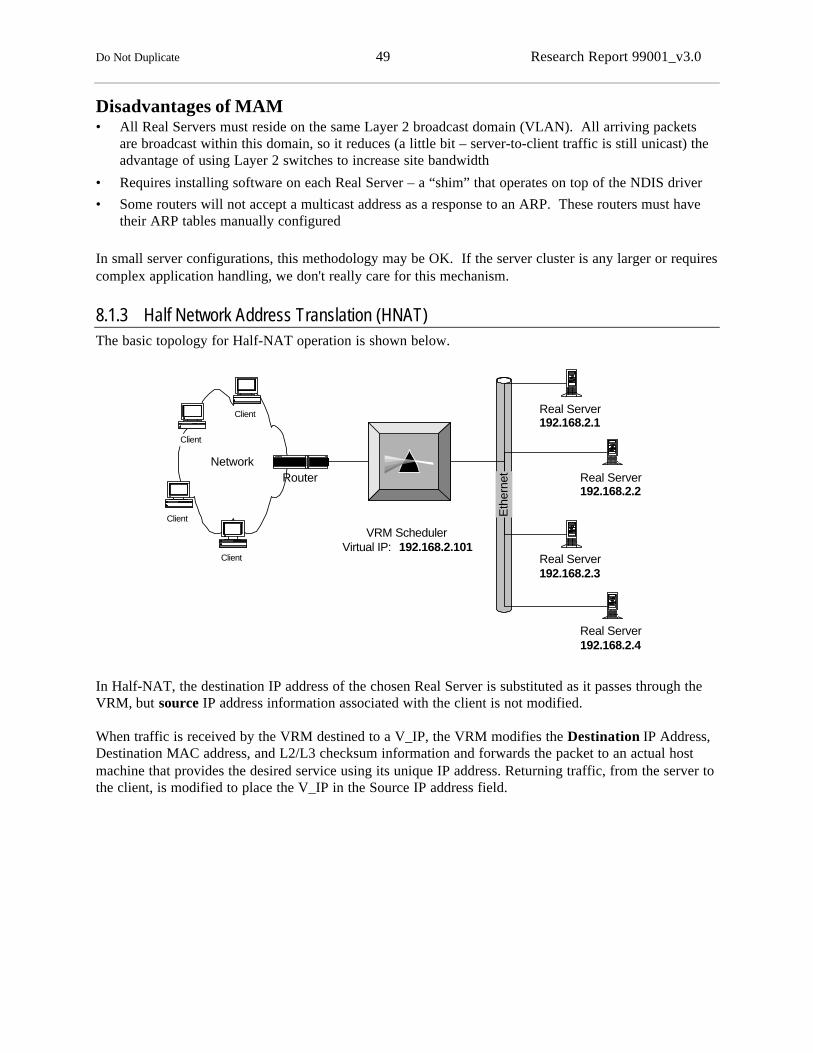
Do Not Duplicate 49 Research Report 99001_v3.0
Disadvantages of MAM• All Real Servers must reside on the same Layer 2 broadcast domain (VLAN). All arriving packets
are broadcast within this domain, so it reduces (a little bit – server-to-client traffic is still unicast) theadvantage of using Layer 2 switches to increase site bandwidth
• Requires installing software on each Real Server – a “shim” that operates on top of the NDIS driver
• Some routers will not accept a multicast address as a response to an ARP. These routers must havetheir ARP tables manually configured
In small server configurations, this methodology may be OK. If the server cluster is any larger or requirescomplex application handling, we don't really care for this mechanism.
8.1.3 Half Network Address Translation (HNAT)The basic topology for Half-NAT operation is shown below.
In Half-NAT, the destination IP address of the chosen Real Server is substituted as it passes through theVRM, but source IP address information associated with the client is not modified.
When traffic is received by the VRM destined to a V_IP, the VRM modifies the Destination IP Address,Destination MAC address, and L2/L3 checksum information and forwards the packet to an actual hostmachine that provides the desired service using its unique IP address. Returning traffic, from the server tothe client, is modified to place the V_IP in the Source IP address field.
Network
Client
Eth
erne
t
VRM SchedulerVirtual IP: 192.168.2.101
Real Server192.168.2.1
Real Server192.168.2.2
Real Server192.168.2.3
Real Server192.168.2.4
Client
Client
Client
Router

Do Not Duplicate 50 Research Report 99001_v3.0
The figure below diagrams how addresses and checksum (and CRC) information are modified in theclient-to-server direction of traffic flow.
The figure below diagrams how addresses and checksum (and CRC) information are modified in theserver-to-client direction of traffic flow.
TCP functions are transparent to the NAT functions occurring underneath them. The client and the serverengage directly in TCP functions such as connection set-up, connection completion, flow control, anderror control.
ClientClientC_MACC_MAC
C_IPC_IP
21552155
8080
037A037A
Checksum
Dst. IP Address
Dst. Mac
Source Port
Destination Port
Checksum
V_IPv_mac
21552155
8080
037A037A
Mac Layer V_V_macmac
c_c_macmac
21552155
8080
03780378
V_IPv_mac
Source IP Address
Src. Mac c_c_macmac
V_V_macmac
l4_l4_vmacvmac
r_r_macmac
Server Load Balancer
C_IPC_IP
V-IPV-IP
B62AB62A
C_IPC_IP
V_IPV_IP
B62AB62A
C_IPC_IP
R_IPR_IP
B628B628
Real IPReal IPR_MACR_MAC
R_IPR_IP
21552155
8080
03780378
r_r_macmac
l4_l4_vmacvmac
R_IPR_IP
C_IPC_IP
B628B628
IP
TCP
Client Real Server
Checksum
Dst. IP Address
Dst. Mac
Source Port
Destination Port
Checksum
Mac Layer
Source IP Address
Src. Mac
ClientClientC_MACC_MAC
C_IPC_IP
80802155215557B357B3
c_macr_mac
V_IPV_IP
C_IPC_IP
82E082E0
V_IPv_mac
80 80 2155215557B357B3
r_macc_mac
V_IPV_IP
C_IPC_IP82E082E0
Real IPReal IPR_MACR_MAC
R_IPR_IP
80 80 2155215557B157B1
c_macr_mac
C_IPC_IPR_IPR_IP
82DE82DE
Server Load Balancer
80 80 2155215557B157B1
r_macc_mac
R_IPR_IPC_IPC_IP82DE82DE
V_IPv_mac
IP
TCP
Client Real Server

Do Not Duplicate 51 Research Report 99001_v3.0
Value Add OptionsWhen the VRM scheduler is a router, the topology of a NAT implementation can be improved such thatfewer wiring changes are needed to introduce the VRM scheduler into the system. This is done byidentifying the VRM scheduler as the default gateway to all the content servers.
In this configuration, all traffic still passes through the VRM in both directions, but the VRM does nothave to be physically wired into the network between the access router and the content server LAN.
Advantages of Half-NAT• (Relative to MAT) Loopback interfaces do not have to be configured on the Real Servers for the
V_IPs
• In theory the Real Servers can be a router hop away from the VRM scheduler. But be careful. Returntraffic must pass back through the VRM scheduler, so the router topology must be well understoodand stable
Disadvantages of Half-NAT• All traffic associated with Virtual Services must pass through the VRM scheduler in both directions
and be modified. Care must be taken in the topology to ensure that all packets return to the clientthrough the VRM because there is no natural reason for them to do so
• Modifications to IP addressing need to be supported by complementary modifications to IP and TCPchecksum fields. If the checksum fields are encrypted, for instance when transport-mode IPSec isused on the server, NAT cannot be used
• When the NAT device is configured as the default gateway on the content servers, you have to makesure that the system is properly configured to support VRM scheduler fail-over. This can get trickysometimes
HNAT is the most commonly used local re-direction technique today. No configuration changes need tobe made on the target servers at all, which makes deployment and on-going management simple.
Network
VRM SchedulerRouter IF IP: 192.168.10.4Virtual IP: 192.168.2.101
Real Server Aethernet i/f: 192.168.10.1
Default GW: 192.168..10.4
Real Server Bethernet i/f: 192.168.10.2Default GW 192.168..10.4
Real Server Cethernet i/f: 192.168.10.3Default GW 192.168.10.4
Client
Client
Client
Client
LAN
Router

Do Not Duplicate 52 Research Report 99001_v3.0
8.1.4 Full NAT (FNAT)In full-NAT, the IP address/checksum information of both the client and server (IP Source Address, IPDestination Address) are modified as it passes through the VRM, in both directions.
Advantages of Full NAT
• Unlike MAT and (practically) HNAT, FNAT allows the Real servers to be installed anywhere in therouted network. Since both the Source and Destination IP information is replaced, the server believesthat the VRM scheduler is the client, and all response frames will flow back to the VRM schedulerthrough the routed network. This could even work over wide area networks, although that isdiscouraged because of the extra WAN hops a packet would take to go from the client to the VRM tothe Real Server, back to the VRM and back to the client
• As with HNAT, no configuration of V_IPs on loopback interfaces on the Real Servers is needed
Disadvantages of Full NAT
• FNAT "hides" the original client's IP address from the server, making troubleshooting and serveraccess logging difficult. The Real Servers believe that all connections are coming from the sameclient (the VRM). This disadvantage can be alleviated if the VRM system provides the granularity oftraffic information usually obtained from the server logs
• FNAT requires translation of both IP fields and well as MAC fields, and all related error checkingfields
The hiding of source IP address from the server is a big issue. Unless the VRM system can re-create allthe information that would have been derived from the server logs, we tend to avoid the use of Full NAT.
8.2 Delayed Binding MechanismsIt is often desirable for an VRM system to use information provided by the client after the TCP session isestablished to influence which Real Server a connection is sent to. For example, URL information isprovided in the HTTP method request, which is only sent after a TCP connection handshaking iscomplete.
The mechanisms described in this section all provide the capability to perform “delayed binding.” Ineach case, the VRM system completes the TCP handshake with the client, inspects the next packet orpackets provided by the client, and creates a connection to the chosen Real Server based on thatinformation. This process requires significantly more processing on the part of the VRM system, but canresult in significant system advantages, especially in the area of state management and persistence.
8.2.1 TCP “Diddling” (TCPD)In TCP “Diddling,” the VRM system completes the TCP handshaking process with the client, fooling itinto thinking it has established a connection with a Real Server. In the process, the VRM system recordsthe initial Sequence # set by the client. In the handshaking process the VRM system responds with itsown Sequence # and records that information for later use.

Do Not Duplicate 53 Research Report 99001_v3.0
After the VRM System receives the desired post-connection information from the client, the VRM systemmakes a “best available server” decision. The VRM system then sends a TCP connection request to thatchosen server, with the same parameters (source IP address, source port number, initial sequence number)as in the original TCP SYN packet. The Real Server will respond with its own SYN packet and Sequence#. The VRM absorbs that packet, but records the offset between the sequence number provided by theReal Server and the original sequence number it provided to the client (and any other differences, such asport numbers). The VRM system then sends an ACK to the Real Server (completing the 3-wayhandshake) and follows that with the client’s GET request.
From that point on, all traffic passes directly from the client’s TCP process and the Real Server’s TCPprocess, but the VRM system interdicts the traffic in the server-to-client path in order to adjust sequencenumbers to match the clients expectations based on its original handshake with the VRM.
Some corner case situations must be handled by the VRM scheduler, even though it is not completelyterminating TCP. An example of this is the handling of IP Fragmented packets. When an IP frame isfragmented, the first fragment contains the TCP header information, but the following frames do not.How is a VRM to handle the frames that arrive without TCP information?
• One approach would be to cache the first arriving fragment, and then re-create the originalunfragmented frames as the rest of the fragments arrive. That’s a lot of work, but would veryeffectively deal with the situation
• Another approach is to drop back to Source IP binding. But that means that all traffic from thatsource (for that service, i.e. HTTP) would suddenly be diverted to one server
Client VRM Real Server
IP
TCP
IP
TCP
3-way handshakeVRM records sequence #forwards the client GET
time
IP
TCP
IP
TCP
IP IP
TCPSequence # "diddling"
3-way handshakeVRM records sequence #Client sends 1st GET
"Best available server" decision
IP
TCP
IP
TCP

Do Not Duplicate 54 Research Report 99001_v3.0
• Another approach is to just drop the packets. Fragmentation shouldn’t occur if the sources set the “donot fragment” bit. MTU negotiation should prevent the need for fragmentation. Something is wrong.Send a notification so we can go figure out what is wrong rather than trying to solve the problem
Advantages of TCPD• Enables “delayed binding” capabilities
• (Relative to TCPG) Less overhead. TCPG does not handle true TCP processing (e.g. windowing, re-ordering, error correction, exception handling). It just handles some TCP 3-way handshakingfunctions and then modifies some bits in the TCP headers as they pass through the device
Disadvantages of TCPD• Traffic must pass through the VRM and be modified in both directions
8.2.2 TCP Gateway (TCPG)In the TCP Gateway mode of operation, the VRM creates separate TCP sessions to the client and to theserver. First, as client connection requests arrive, a TCP session is created to the client. After thehandshaking process is complete and the client sends to HTTP Get request, the VRM can choose a RealServer based on the specific content or resource requested. A separate TCP session is then created to thereal server. The intermediary VRM passes information between the TCP Sessions.
Client VRM Real Server
IP
TCP
IP
TCP3-way handshakeClient sends 1st GET
time
IP
TCP
IP
TCP
IP
TCP
IP
TCP
3-way handshakePasses on 1st client GET
"Best available server" decision
IP
TCP
IP
TCP
IP
TCP

Do Not Duplicate 55 Research Report 99001_v3.0
Advantages of TCP Gateways• A completely general solution. Could be used as the foundation for an application gateway or for any
other mechanism where observing or modifying application data is required, such as rate shaping andapplication-level traffic monitoring
Disadvantages of TCP Gateways• Traffic must pass through the VRM scheduler in both directions
• Cost/Performance. There is a lot of TCP overhead associated with this approach. Each packet mustbe pass through two TCP processes within the VRM
Because of the overhead, few VRM products we are aware of today use TCP Gateway.
8.2.3 TCP Connection Hop (TCPCH)TCP Connection Hop is a proprietary mechanism used by only one vendor today. TCP Connection Hopis a lot like TCP Diddling, but the functions required in the client-to-server path are separated from thefunctions required in the server-to-client path. This is accomplished by installing software on each RealServer to perform the server-to-client functions.
Network
VRM SchedulerManagement IP: 192.168.2.15
Virtual IP: 192.168.2.101
Real Server Aethernet i/f: 192.168.2.1
Loopback i/f: 192.168.2.101
Real Server Bethernet i/f: 192.168.2.2
Loopback i/f: 192.168.2.101
Real Server Cethernet i/f: 192.168.2.3
loopback i/f: 192.168.2.101
ClientClient
Client
Router
TCPHandshake TCP handshake
Server-to-ClientTraffic
TCP Diddlingperformed on
the Real Server
The VRM scheduler completes the TCP connection process for the (as yet unidentified) Real Server asconnection requests arrive from clients. When further information relevant to the active policy arrives(such as the URL), the Real Server can be chosen based on the specific content or resource requested.The scheduler then sends a message to that Real Server telling it that it wants to establish a TCPconnection to an identified Virtual Service as a proxy for the client. It uses the same client IP address,source port numbers and sequence number information as was established by the TCP connection set-up

Do Not Duplicate 56 Research Report 99001_v3.0
process with the client. The Real Server then “takes ownership” of the TCP connection and respondsdirectly to the client, in a manner that is transparent to the client.
Advantages of TCP Connection Hop• As with TCP Gateways, more explicit resource, content, or user information (such as cookies) can be
used to influence the decision about which server to direct the request
• As opposed to TCP Gateways and TCP Diddling, the VRM is only involved in traffic flow from theclient to the server, which are generally just ACKs. After the initial connection set-up process, thesepackets just require simple encapsulation. All packets from the server-to-the-client bypass thescheduler completely. This is the only delayed binding mechanism that supports the direct-to-clientfeature
• The “hiding” of real server IP addresses is maintained
• Solution can be scaleable because of the partitioning of functions performed between the schedulerand Real Server
Disadvantages of TCP Connection Hop• Requires special and proprietary software on each Real Server
• Represents an added load on each Real Server (however this may be more than offset by the reducedload on the scheduler)
8.2.4 Value Added Features Enabled By Delayed Binding
URL Based SchedulingDelayed binding allows the VRM system to observe each client's URL request, and compare it againstpredefined rules to make a decision about which server to send the request to.
URL-aware schedulers can also potentially support the following two value added features:
• URL Repetition. At least one vendor has suggested that examining the most recently accessed URLs(files) and sending similar requests back to the same servers will further optimize the load balancedsystem. It is argued that the recently accessed URLs/files will still be cached on the web server, andtherefore the content can be more quickly accessed with less load on the web server by sendingrequests for the same URL/file to the same server. The advantage gained here is totally dependenton:
• how much time has passed since the file was last accessed
• how busy the server is that had recently retrieved the file
• whether the VRM latency to provide the feature is smaller than the latency advantage gainedby achieving a cache hit

Do Not Duplicate 57 Research Report 99001_v3.0
• Passive Content Verification with Re-Direction. Many products today parse the content returnedby web servers to examine the Return Codes (the first bytes). This can be used to identify failedservers, applications, access to databases and file systems, etc. The 400, and 500 level Return Codessometimes indicate problems with a particular entity or path in the site, which can be alleviated by re-sending the original request to another server. The Passive Content Verification with Re-Directionfeature achieves this. When a TCP connection is established to a server, information about theoriginal request by the client is stored. If the response from the originally chosen server indicates aproblem that may not exist on another server, the initial request is re-sent, but to a different server.The client is potentially completely transparent to this process, receiving no error messages, requiringno reloads, etc.
SSL Session ID-Based BindingWhen a client and server decide to engage in an encrypted session, they must negotiate variousparameters associated with authenticating the client, how the encryption and compression will beperformed, what the shared key to de-encrypt is, and a few other factors. In SSL 3.0, once thatnegotiation is complete, an SSL session ID is agreed to, which is communicated in clear text format,between the client and server for all interactions related to that session. The session itself may extendacross many, many TCP Connections, with (sometimes) long gaps of time between TCP Connections.
The VRM system should ensure that all TCP Connections related to a particular SSL session aredelivered to the same content server. Delayed binding allows the VRM system to look at the SSL SessionID information, which is only sent after the TCP handshaking process has been completed.
Cookie-Based BindingSites can set cookies on client browsers, for either permanent use or temporary (session) use. The clientbrowser communicates these cookies with each HTTP GET request. The VRM system must performdelayed binding in order to be able to view the HTTP GET and therefore, the cookie.
The cookies can be useful to track for either persistence reasons or preferential services reasons. In thefirst case, the cookie can be tracked throughout a shopping cart session, with only issue being tracking auser as they go in and out of an SSL phase. In the second case, a site could authenticate a user via apassword, and then set cookies to identify them as a gold customer, silver customer, or “proletariat.”Such labeling could be used if the site becomes congested and preferential services policies start to kickin.

Do Not Duplicate 58 Research Report 99001_v3.0
8.3 Mechanisms Summary
Mechanism DelayedBinding?
Direct toClient?
Avoid Loopback i/fAdministration?
Avoid Softwareon Real
Servers?
MultipleSchedulers forsame services?
MAC Address Translation No Yes No Yes Yes
MAC Multicast No Yes No No Yes
Half NAT No No Yes Yes No
Full NAT No No Yes Yes Yes
TCP Diddling Yes No Depends Yes No
TCP Gateway Yes No Yes Yes No
TCP Connection Hop Yes Yes No No Yes
In general, except for the smallest and most stable applications, we recommend choosing products thathave an option for a mechanism that performs delayed binding as well as an option for amechanism that performs immediate binding. You’ll sometimes use delayed binding for HTTP andimmediate binding for all other protocols.
Within those categories, it doesn’t matter too much what the exact mechanism is. MAT is required forsome non-server load balancing applications. And MAT is generally adequate for server load balancing.But if you need to have Real Servers sit behind routers, or if you want to avoid server re-configuration,Half-NAT is a better choice. We wouldn’t base a product decision based on whether it performs MAT orHalf-NAT; we’d base it on other factors and then use whatever options the product offers.
For Delayed Binding, TCP Connection Hop has some technical allure, allowing direct-to-client trafficflows. But it requires deployment of software on the Real Servers (which doesn’t bother us but doesothers). More importantly to us is that it is a proprietary mechanism supported by only one vendor. Sochoosing that mechanism implies choosing a specific vendor, which is not something we can generallyendorse. If the vendor meets your requirements for other reasons, by all means take advantage of themechanism. If not, choose a vendor who supports the right set of features for your application and usetheir TCP Diddling mechanism. In most cases, that also works well.

Do Not Duplicate 59 Research Report 99001_v3.0
99 MMuullttii--SSiittee LLooaadd BBaallaanncciinnggMulti-site load balancing is the logical extension of local load balancing: applications and content aredistributed to multiple geographically dispersed sites. It allows you to make the application/content beingserved that much more available and scaleable by avoiding the potential major outage or congestion that asingle site may experience. It has the potential additional benefit of placing the content closer to yourmajor user populations, which can improve user experience and lower the cost of transporting the contentby conserving WAN bandwidth.
Consider, for example, an online media-store such as Amazon.com. Clearly, their site is popular and theyhave customers scattered across the world that they want to provide the best browse-and-purchaseexperience that they can. By performing web server log analysis, they can easily track from where themajority of their customers access their site.
Imagine they determine that 30% of their customers are located in Europe. By performing furtheranalysis, they determine that many network retransmissions occur from their servers when serving usersin Europe, and they have a higher than normal “stop button hit rate” when serving requests from Europe.From this straightforward analysis, one can easily come to the conclusion that European users aresuffering from the network constraints between North America and Europe, their user experience may bepoor and this may affect their purchasing behavior.
This data may lead them to establish a European mirror site of their North American site(s). A simpledeployment model might involve them only placing relatively static content at the site, such that the sitehandles “catalog browsing” but the primary North American site handles purchasing. This site wouldalso be used as a backup in the event that any other mirror site became unavailable due to failure orcapacity limitations.
The Multi-Site Solution ModelA multi-site solution does involve a more complex topology and setup, but it can really be describedsimply.• A multi-site solution is a group of individual sites that generally have some number of servers
deployed in a full network, with the same content and applications available to them (let’s call themcontent sites)
• There are one or more multi-site capable VRM schedulers (MS-VRM) that are aware of each contentsite. These may be deployed at one or more of the content sites, or they may be deployed at a centrallocation
• User requests arrive at one of the MS-VRM schedulers, are evaluated by the configured multi-sitepolicy, and are then dispatched to one of the content sites for application/content serving. Userrequests may arrive at the MS-VRM as a DNS Request, which comes from the user’s local DNSserver or they may arrive as TCP/UDP requests
• Local load balancing solution is really an option at each site; it’s recommended but not required. Thecontent site can be just a network and one server
• Similarly to local VRM solutions, multi-site VRM solutions use Feedback to determine general site,server and application availability; they use Policies to determine how to distribute users and requestsamong the sites and servers ; they use Mechanisms as the method of dispatching users and requeststo multiple sites

Do Not Duplicate 60 Research Report 99001_v3.0
See the World:The Life of an HTTP Session during Multi-site Load BalancingRemember our lowly HTTP session and its life experiences? First, it experienced direct servercommunication; then it was told where to go by a load balancer. Now it gets to see the world… thedestinations your lowly HTTP request could see! Paris, Tokyo, Madrid, Detroit…
1. The user loads their browser application, and selects a site to communicate with – www.acuitive.com.The browser executes a DNS lookup for the fully qualified hostname.
2. This DNS lookup request is directed at the user’s local DNS server. If this local DNS server has anIP address in cache corresponding to the hostname, it will respond directly back to the user’s browser.If it does not, it continues the DNS resolution process. (A more descriptive treatment of the DNSprocess can be found in a later section).
3. This is the first opportunity for an MS-VRM scheduler to get involved. Some MS-VRM units act asDNS Servers, and as such, they serve as the Authoritative Name Server for the hosts-domains forwhich they are configured. The DNS request arrives at the MS-VRM unit, and it uses one of theMulti-site VRM Policies discussed in a later section to determine which site to dispatch the user to. Itdispatches the user to the chosen site by answering the DNS request with an IP address thatcorresponds to a server (real or virtual) at that site.
4. The DNS response goes back to the users local DNS server as one or more IP addresses, that in turnforwards them to the user’s system.
5. Once the user’s system has an IP address to connect to, it begins the TCP connection process. This isthe second point at which an MS-VRM system may get involved. The MS-VRM system may be thetarget of the TCP connection request, and may choose to dispatch the user to the site deemed bestusing a Multi-Site Policy.
6. If the TCP request arrives at a local VRM, it is handled with the local VRM policies and mechanismsdiscussed in the previous section. Thus, the entire VRM system may be built from MS-VRM systemsdispatching users to sites, and local VRM systems processing user requests at each site.
7. If an MS-VRM system (or a local VRM system with certain features) receives a request it cannotfulfill locally, the user’s request may be redirected to the next best site/server using one of severalMulti-Site Mechanisms, discussed in the following sections.

Do Not Duplicate 61 Research Report 99001_v3.0
9.1 Multi-Site FeedbackAt a minimum, multi-site VRM products need to know the status and health of the content sites to whichthey may dispatch users, to ensure user requests do not go unfulfilled. They must also support some formof load distribution capability, and they may use feedback systems to learn the available capacity fromeach content site. Most multi-site feedback implementations today involve extending local feedbackcapabilities, and many implement a proprietary protocol to communicate status and performanceinformation between the content sites and the MS-VRM schedulers.
9.1.1 Content Site Testing: Extensions to Local FeedbackThe techniques used for local server health awareness are also attractive as multi-site health awarenesssolutions.
It is possible to extend most of the local feedback mechanisms (Device ICMP PING, TCP ConnectionVerification, Server Resident Monitoring, etc.) to serve as feedback mechanisms in a multi-site VRMsystem. However, we tend to only recommend Active Content Verification (ACV) and DynamicApplication Verification (DAV). ACV/DAV can be used to test content sites and their respective servers,to ensure:• that the site’s network is healthy: it can pass requests and responses
• that, if there is one present, the local load balancing solution is working: it can accept and locallyhandoff application requests
• that at least one server is functional: ACV/DAV requests are fulfilled by an application/content server
This technique does not require any real modifications to the ACV method, as long as the MS-VRMscheduler is capable of sending an ACV request anywhere. It simply requires configuring some differentparameters than you would for local load balancing. A local VRM scheduler is normally configured torecognize its locally attached servers, which it then performs ACV/DAV on to verify health. Configuringa MS-VRM scheduler usually requires configuring one or more “remote servers,” which might be V_IPsrunning in each site’s own VRM scheduler, or they might simply be geographically remote serversinstalled on a network.
Issues• The testing from the MS-VRM scheduler to a content site requires the application/content server to be
the responding entity from the site. Even though the application requests may be directed at a localVRM scheduler at the content site, the request should be dispatched to a local server for requestfulfillment. In other words, the MS-VRM scheduler must not simply check the local VRM scheduler,but the servers/applications as well. That is why ACV and DAV are good remote testing options
• If the content site has a local VRM scheduler, using ACV/DAV does not imply that all servers at acontent site are tested during each health check interval. To the receiving VRM scheduler, the ACVrequest should look like any other client request, and it will dispatch it to the best local serveraccording to its configured policies. During that health check interval, only a single server is tested
• Health checking parameters from a MS-VRM scheduler for content site testing will have to be moreforgiving than they would be for local server testing. The delays expected when testing a site inAustralia from an MS-VRM scheduler in Montana, USA will be significant; thus, you would notwant to set your health check period to an interval of two seconds. Any other tunable parameterssuch as timeouts and retries should also be set accordingly, and may take some experimentation

Do Not Duplicate 62 Research Report 99001_v3.0
• We don’t consider the other methods of feedback (ICMP, TCO, TCV) to be viable in a multi-sitesolution. If there is no ACV/DAV capability for a certain application in a multi-site environment, wesuggest using a reliable external probe monitoring system that can signal any/all of the MS-VRM(and potentially local VRM) units of an application or server failure
• TCV and DIP are not useful because they simply don’t provide enough visibility into serverapplication availability. While they might indicate basic site and server status, we feel that any multi-site VRM system is a large investment towards reliability, and you do not want to compromise thatreliability by using sub-par feedback methods
• Server-based resource monitoring may be a useful extension in this environment to have betterawareness of server application health. However, relying on the server-to-VRM protocols in a multi-site environment may be problematic. Only use them as additions to ACV or DAV, and only if theserver-to-VRM protocol will be robust
9.1.2 Inter-VRM Protocol (IVP)Most multi-site VRM vendors that support both multi-site and local VRM products has a proprietaryVRM-to-VRM protocol (IVP) that passes between the VRM schedulers at content sites and the MS-VRMschedulers, and/or between MS-VRM schedulers. These protocols can be used to exchange server health,client proximity, site load and performance information, can also be used as keep-alives, and are veryvendor specific. In general, a VRM scheduler may use IVP to provide the following information:• Server Health: The local VRM scheduler informs the MS-VRM scheduler how well its servers are
performing (push protocol). Another variation is for the MS-VRM scheduler to ask all the localVRM schedulers how well their local servers are doing (pull protocol from all sites)
• Client Proximity/Performance Info Exchange: A client is trying to connect to a content sitethrough an MS-VRM scheduler. The MS-VRM scheduler asks all the local VRMs to perform a testback to the client to see how far they are away from each site (site proximity request). Once all siteshave completed the test, the schedulers at each site inform the polling MS-VRM of the client’sproximity (proximity responses). See the Policy section below for additional information
• Site Load and Performance: Each local VRM scheduler has awareness of its own site load andperformance (users, connections, other 2nd order metrics) that can be communicated to the MS-VRMscheduler. This information is then used to make user request distribution decisions. At least onevendor has used ACV in combination with response time measurement information that is publishedto all sites from all sites. See the Policies section below for further information
• Keep-Alives: IVP can also be used as keep-alives, where if a local VRM fails to push any newinformation out or fails to respond to pull requests, the site is considered unhealthy, and potentiallyineligible to receive user requests. This keep-alive technique should only enhance, but not replace theACV/DAV multi-site extensions to monitor site/server health
Issues• As with the other health check methods, IVP protocol timers should be set accordingly, taking into
account the fact that sites are separated by potentially slow and/or latent links
• These protocols can behave very much like routing protocols on a small scale, where the availabilityand performance metric information is exchanged in either regular or triggered fashion. However,each vendor’s implementation is different, so there should be no expectation of interoperability, andyou should make sure you examine each vendor’s capabilities

Do Not Duplicate 63 Research Report 99001_v3.0
• Make sure the vendor has awareness of all local VRM schedulers in each content site. They shouldcommunicate information to/from any standby units that are installed at the site, not just the activeunits
• Make sure any multi-site vendor you are considering is not using a clear-text protocol for their IVP,since these protocols may flow across the Internet and may result in the alteration of behavior of acritical resource
Value-Added OptionsIts is possible to exchange content availability information using IVP, where each MS-VRM schedulernot only knows the status of each server, but also the status of the content on each server as well. Used incombination with URL Parsing and HTTP-Redirect, this allows them to more accurately dispatch userrequests to the best site/server. Each MS-VRM scheduler knows which other units have access to thecontent being requested, and knows the performance and availability of those sites; therefore the user canbe directed at the best content site.
9.2 Multi-Site Oriented PoliciesA local load balancing VRM product makes a decision on what server to send the user request to, usinglocal policies. A multi-site load balancing VRM product makes decisions on what site to send the user to,based on one or more of the multi-site policies described in this section.
The usefulness behind the policies available is in the eye of the beholder. The content publisher is goingto mostly be interested in providing the best user experience, so in addition to the reliability factor, theymay want to determine the best site to send their users to based on responsiveness metrics. The serviceprovider may be interested in reducing their WAN backbone by preventing requests from traveling acrossthe country or the world “unnecessarily.”
9.2.1 Static Client-Site Preferences (SCP)
Source Address PreferenceThe easiest multi-site policy to explain involves the use of static tables that define client subnet-to-sitepreferences.
Examine the following example table:SourceSubnet
SubnetMask
Preferred Site #1 Preferred Site #2 Preferred Site #3
193.128.0.0 255.255.0.0 vrm-rtp.acuitive.com vrm-sanjose.acuitive.com vrm-paris.acuitive.com204.165.121.0 255.255.255.0 vrm-boston.acuitive.com vrm-rtp.acuitive.com vrm-paris.acuitive.com172.176.0.0 255.255.252.0 vrm-rtp.acuitive.com vrm-boston.acuitive.com vrm-sanjose.acuitive.cometc… … … … …
This table shows source subnets of some size (as defined by the subnet mask) and the static sitepreferences of the administrator. Each client within the source subnets should prefer to go to the sitelisted in Site #1, then prefer Site #2, then prefer site #3.

Do Not Duplicate 64 Research Report 99001_v3.0
Thus, it is very easy to describe how a given client will be directed to a site to get access to applicationsand content. A client request arrives at one of the multi-site VRM schedulers, the SCP table within thatunit is consulted for site preference information, and the client’s request is dispatched to the preferred site.
Without any automation of the generation of these tables, the potential scale of table sizes andadministrative complexity may make this implementation difficult to use. In the above table, there are atleast four sites that distribute applications and content for Acuitive: San Jose, Boston, RTP and Paris.Acuitive, having a wildly popular website, has the potential of receiving requests from anywhere in theentire Internet, which means there are millions of possible source subnets that might access our content.Well, administering millions of static client-site preference entries by hand is not very feasible, so let’sexplore the alternatives.
• You could assume that the table will just contain the exceptions to a generalized set of site rules. But,it would be hard to come up with a set of general rules to calculate client-site preferences, so thatwon’t work
• You could use longest prefix matching algorithms, where you start the table with defined networks oflong masks (255.255.255.0) and end the table with short masks (255.0.0.0). Any overlap between thelong mask entries and the short mask entries will be evaluated with the long mask entries “winningthe overlap tie.” You’ll make your life easier by making further assumptions that any class A networkwill be summarized with only a few entries. The drawback here is that you’re still administering lotsof entries, and organizations that have class A addresses (like IBM and General Electric) will have nosite choice granularity
• You can write an application or script to use the content site routers’ BGP tables to automaticallycompute a list of static entries. The script would retrieve the border routers BGP tables on a periodicbasis, and compute the best-site static table entries based upon the available path-vector informationto other AS’s, and the networks contained in them. This would allow you to automatically computehow far each content site is from every potential source network by AS-hop count. This methodshould be very reasonable to implement, assuming you have access to the BGP tables in the routers ateach content site, and you write the application to compute AS hop distances and make comparisonsbetween each of the content sites
• You can be more analytical about analyzing your clients’ properties, like what their source networksare and what their performance experience is, and then use additional automated methods to computethe static client-site preference tables. For instance, and application that analyzes your web serverlogs could produce the topN list of most popular source networks, which you could then use to createthe static source preferences
Source Domain LookupAnother method that is similar to Source Address Preferences is called Source Domain Lookup. Thisinvolves the creation of static tables that reflects site preference based on the Source DNS domain therequest is originating from. Thus, we could create a static table that looks like:
Source Domain Preferred Site #1 Preferred Site #2 Preferred Site #3.ibm.net vrm-rtp.acuitive.com vrm-sanjose.acuitive.com vrm-paris.acuitive.com.mit.edu vrm-boston.acuitive.com vrm-rtp.acuitive.com vrm-paris.acuitive.com.fr vrm-paris.acuitive.com vrm-boston.acuitive.com vrm-sanjose.acuitive.cometc… … … …

Do Not Duplicate 65 Research Report 99001_v3.0
When a user request arrives at the MS-VRM scheduler, it performs a Reverse DNS lookup on the sourceaddress of the request. The MS-VRM unit scans the Source Domain Preference table and finds the mostexact entry that matches the RDNS response. The MS-VRM scheduler then dispatches the user to the sitelisted within the preference entry.
This policy allows an administrator to quickly setup site preferences that are human-understandable, andcan be as short or as long as the VRM administrator cares. If the administrator wants simple policies thatpoints users within specific countries to the appropriate site, then they have about 200 entries to create.To further optimize the access within North America, they could identify the top 10, top 100, or top 1000sources of requests from their webserver logs and configure them as well.
Value Added OptionsUsing some of the second order metrics described later, such as Packet Retransmission monitoring or SitePerformance Testing makes SCP a fairly good methodology.
Advantages of SCP• Can (potentially) keep traffic localized into broad geographical regions or predictable topologies
• Prevents system over-reaction and instability
Disadvantages of SCP• Doesn’t react automatically to changes in network and site performance
• Does not provide granular balancing of load between sites
• Requires manual administration (or partially automated administration) of the SCP preferences
9.2.2 L3 Topological Proximity Testing (TPT)This policy allows clients to be dispatched to sites based on the topological closeness to theservice/application resource. Client requests arrive at one of the multi-site VRM schedulers, whichevaluates its knowledge of this client’s Layer 3 proximity to one of the content sites. If it has priorknowledge of the best content site to dispatch this client to, it quickly reverts to one of the multi-sitedispatch mechanisms described later. If it does not have knowledge of the client’s proximity to one if thecontent sites, it must use the TPT method to determine the best site to dispatch the client to.
This process requires the VRM schedulers at each site to be capable of performing TPT functions, whichmeans they are either multi-site capable themselves, or are local VRM products with multi-site testingextensions.

Do Not Duplicate 66 Research Report 99001_v3.0
How TPT Works
1. An unknown client’s request arrives at an MS-VRM scheduler (LDNS or Client TCP).2. The MS-VRM scheduler tells some/all of the VRM schedulers at the content sites (via IVP) to
perform a proximity test back to the client. As an Added Value option, the MS-VRM scheduler maydispatch the client to a “default site” to avoid long testing latencies (Initial Client Pass-Through).
3. Each content site VRM scheduler tests the proximity of the client, usually via PING, Traceroute or aTCP connection. Once a response to the test comes back, the proximity of the client is determined byinspecting the IP TTL remaining, which (sort of) represents router hop count to the client.
4. Once a given VRM scheduler determines the proximity of the client, it informs the MS-VRMscheduler via IVP. Once the MS-VRM scheduler that received the client’s request hears back fromthe content site VRMs, it can compare all of the returned TTL values and should now know whichsite is closest to the client. This MS-VRM scheduler will inform any other MS-VRM scheduler thatwill receive multi-site client requests of the client’s proximity information, so that they may alsomake appropriate multi-site decisions based upon this learned information.
5. If the MS-VRM did not use Initial Client Pass-Through, it will now respond back to the client requestto inform them of the best site.
6. Subsequent requests from this client (and in practical implementation terms, any client from the samesubnet) will be evaluated with this client network distance information, and may be dispatched to theclosest site, assuming the site has available resources.
MS-VRM Site
Site 1 Site 4
Site 2
Clients LDNS
Site 3
Client System
ClientNetwork
1
2
2
2
2
4
4
43
3
3
3
5
6
ClientLocation
State

Do Not Duplicate 67 Research Report 99001_v3.0
Advantages of TPT• TPT is simple and can be applied regardless of how many networks, types of routers, etc. are
associated with all the various possible paths from a client to a VRM site• It can provide data that may directly correlate to the topological closeness of clients and the sites they
may access for content and applications. This is especially true if the clients and the sites/servers areall controlled by one organization, or if the number of paths between a limited number of clients andthe sites is well understood
Disadvantages of TPT• Each MS-VRM scheduler must maintain a certain amount of state information on each client source,
to be able to make an intelligent multi-site decision the next time the opportunity comes up. The stateinformation required includes source network plus site proximity. For busy application/content siteswith lots of source clients, this may require significant amounts of memory to be dedicated to justremembering this state information. Luckily, memory is cheap, but make sure that your multi-siteVRM vendor can support maintaining proximity tables that could occupy 16MB or more of RAM, inaddition to all the other features you’d like
• For every unknown client (subnet), there will be traffic generated from at least (1) test per content siteand two IVP exchanges per site. Assume two packets per event, per site – that’s six packets (plusprotocol overhead for either TCP or UDP) per new client, per site. For a busy site, assume 750 newclients / client lookups per minute x 6 packets = 4500 packets per minute. Hmmm…
• Testing using PING, Traceroute and/or TCP connections, TPT may or may not make it through to theclient, because of security and traffic policies all along the network path from the VRM to the client.Vendors have assured us that they have worked out various techniques to avoid the pitfalls of tryingto test back to a client that is behind a firewall, but we remain skeptical. Imagine if there weremultiple paths to the client, and one VRM system’s TPT made it through, and one did not. Whichsite is better? How can you be sure?
• Using Layer-3 hop count (really TTL) as a metric does not take into account Layer-2 topologies thatmight negatively (or positively) affect the outcome of the tests. Frame relay, ATM, applicationproxies and firewalls may skew the TTL values returned by the VRM schedulers, or render themuseless. Is it really better to take a path that has 36 Frame Relay hops and two router hops than totake one with 4 router hops? That’s the decision that TRT would make
• By the time the VRM schedulers test back to the clients, the information might be old news. Tocombat this and the inaccuracy possibilities mentioned above, periodic re-tests of client sourcenetworks and statistical calculations on the results will be required to ensure the data remains at leastsomewhat useful. We’re not sure if any vendor implements this re-test technique today, so make sureyou ask
• As we’ll discuss later, the VRM scheduler may actually be testing the client’s DNS server instead ofthe client. This is often not an accurate representation of how far the real client is away from theapplication/content sites. Also discussed later is the issue of DNS caching in the client’s computer aswell as their local DNS server, and how it may negatively impact multi-site load balancing and failurerecovery behavior
We don’t believe that TPT is very useful in the real world.

Do Not Duplicate 68 Research Report 99001_v3.0
9.2.3 Client Path Performance (CPP)This policy allows clients to be dispatched to sites based on content site-to-client path performance.
The method involves much of the same algorithms and evaluations as TPT, but uses measured clientresponse time or path packet drop rate as the metric rather than TTL or hop count values. Each(capable) local VRM scheduler measures the response time (and/or packet drop rate) from each site to therequesting client by sending a PING or TCP connections request and timing the response. The responsetime (or packet loss rate) information is then passed off to the MS-VRM scheduler, which analyzes it tosee which site experiences the most responsive communication.
Advantages of CPP• It can provide data that may directly correlate to the (basic) performance of clients for the sites they
can access. This is especially true if the clients and the sites/servers are all controlled by oneorganization, or if the number of paths between a limited number of clients and the sites is wellunderstood
• If your goal is to maximize user experience, then CRT is one of the choices to help you optimize forthat goal
• In theory, CPP can allow you to avoid points of congestion in the Internet or at content sites
Disadvantages of CPP• Measuring client response time or packet loss rate across the Internet may produce results that swing
by as much as a factor of 10 from one period of time to the next. This may result in improperpreference of one site over another, simply because of a period of network congestion encountered onthe ‘Net. This issue makes CPP just as inaccurate as hop count testing
• Same packet exchange problem as TPT• This method requires the same amount of state information on each client source, just as TPT does• This has all the pitfalls associated with testing using PING, Traceroute and/or TCP connections• Periodic re-tests of client source networks and statistical calculations on the results are required, the
same as TPT. In the case of packet loss rate, a significant amount of traffic may need to beintroduced into the network obtain recent, relevant, and statistically significant information
• The same DNS issue exists with this method as with TPT
We don’t believe that CPP should be used as a primary Policy. However, we do believe that CPP canbe useful as a secondary/threshold-oriented policy. E.g. “Always send users form geographical area Z tocontent site 6, unless the delay for the user to get to that site exceeds 4 seconds, in which case send themto the site deemed to have the least delay path.” As a secondary policy, we prefer using delays overpacket loss rates.

Do Not Duplicate 69 Research Report 99001_v3.0
9.2.4 Routed Path Analysis (RPA)This methodology is slightly different than the above two methods: it does not require much activetesting, but instead relies on the routing topology tables that each Internet BGP-speaking border routerand/or each interior router maintains to route traffic across the Internet and interior networks.
BGP deals with Autonomous Systems, which are collections of networks as defined by the networkadministrator. When a BGP border router is setup, it informs it peer routers about all of the networks thatcan be accessed through it, and learns what networks it can access through its peers. This information isrepresented in a routing table that is a summary of all the AS’s the router can get to, the routed path to getthere and the networks along the path.
These routing tables contain what are called path vectors that show the AS-hop-by-hop path between theborder router and any destination AS that is out some particular interface. Thus, the path vectors can beexamined and you can determine how many AS’s must be crossed, or hopped through, to get to anyendpoint AS. This information can be used to calculate the rough topological distance from any multi-siteVRM data center, and any client source AS.
Example: There are four multi-site VRM data centers in the world for acuitive.com, each with InternetBGP-speaking border routers. Assume that these border routers can each get to every destination in theInternet. The BGP tables within the routers are periodically downloaded and path vector analysis isperformed on them for every destination AS. This analysis will determine which VRM data centers areclosest to each potential client AS in the world.
BGP Path Vector
info via IVP
BG
P
Pa
th
V
ec
to
rin
fo
via
IV
P
BG
P Pa
th V
ecto
r
info
via
IVP
BGP Path Vector
info via IVP
Site 1 Site 4
Site 2
AS
AS
AS
AS
ASAS
AS
AS
Clients LDNS
Site 3
AS
AS
AS
Target AS#5024
AS
AS
MS-VRM Site

Do Not Duplicate 70 Research Report 99001_v3.0
For instance, if a particular client AS is #5024, and is reachable from each VRM data center, we can useAS path vector analysis determine the best data center to host clients coming from AS#5024:
Data Center #1 à AS#4092 à AS#9023 à AS#8921 à AS#11321 à AS#5024
Data Center #2 à AS#2214 à AS#112 à AS#4321 à AS#5024
Data Center #3 à AS#349 à AS#123 à AS#5024
Data Center #4 à AS#4092 à AS#1013 à AS#5932 à AS#11321 à AS#5024
Based on analyzing the distance from each data center to AS#5024, we know that data center #3 istopologically closest, according to AS hop counts.
Value Added OptionInterior Route Path Cost. If there are two or more target content sites within the Autonomous System, itmight be useful to take into account the path cost between the border of the AS and the candidate contentsites. This requires IVP enabled border routers at the content AS, to determine which interior content siteis closer to the ingress point of the requests.
Advantages of RPAThis method is better in certain respects than TPT or CPP testing, because it can be done on a scheduled,periodic basis and does not have to be performed in “real time.” Thus, the site preferences for anyparticular client community (as contained in a given AS) can be pre-determined. Also, this methodallows for an external application to perform the analysis, which generates output that could be loadedonto multi-site VRM schedulers that support static client-site preference capabilities.
Disadvantages of RPAIn certain respects, this method is worse than the TPT or CRT methods, because it represents a grossapproximation of where the client is in relation to the available data centers. It does not take into accounthow each AS is built and doesn’t account for the speed at which traffic will transit into and through eachAS. The path to AS#5024 may be shortest from Data Center #3 from an Internet perspective, but it mayhave to traverse twice as many physical router hops or cross slower links, as compared to anyone of theother paths.
Also, this method implies access to routing information from routers at each of the content sites andpotentially some routers close to the BGP borders. This may require running special versions of routingcode, or running yet another device near the content site to gather routing topology information.
This method may introduce a significant amount of IVP traffic, if this method is used in real time as userrequests arrive at a MS-VRM scheduler.
We don’t tend to use or recommend RPA.
9.2.5 Site Performance Measurement (SPM)One vendor has extended the use of ACV to perform application response time checking between contentsites, which are considered to be peers. When an MS-VRM scheduler at a site performs ACV to anothersite, it measures the total time elapsed from the beginning of the ACV (TCP SYN) until the final frame ofthe session is passed (FIN ACK). Since the testing involves ACV from one site to another, most of the

Do Not Duplicate 71 Research Report 99001_v3.0
major components at each site will be tested for availability and throughput (routers, local networks, localload balancers, servers, etc).
Performance data from all tested content sites is collected by the testing MS-VRM scheduler, and is thendistributed among all sites using an IVP. Every site conducts these ACV tests, and communicates theresults via an IVP. All of this information is aggregated by each site, which results in each site computingthe same [N x (N-1)] matrix of information for N sites. Thus, if there are six content sites within themulti-site system, each one will test its five peer content sites, resulting in 30 individual response timetests.
An example response time matrix is shown below:
Site Performing Test(measured in ms)
A B C D E F
Site Under TestA 3155 107 343 113 641B 292 1314 378 813 187C 1364 207 3869 995 3883D 197 2490 1997 1190 3390E 3702 1106 1743 2344 468F 1759 1409 683 2235 419
Using this response time matrix and statistical calculations, client request distribution decisions can beinfluenced, with the intent to send client requests to the “best performing” sites. Looking across the rowsat how well each site responded to tests, sites A, B and D are performing well, compared to site E.Therefore, [A B D] would be preferred over [E] when user requests are answered.
Issues• The number of sites that are involved in the site performance testing matrix will dramatically affect
the statistical significance of the computation. If there are only two sites, there will only be one pieceof response time data available per site
• If there are a large number of sites, the amount of testing goes up dramatically
• The path between the sites may be different than the path taken by clients to get to the sites, throwinginto question the value of the data in those situations. An example of this would be a back-channelnetwork between the sites that is different than the Internet connections that clients will take to accessthe site
• Depending on the number and location of the sites, this may be useful only as a second-order oradditional metric. For instance, if there are 4 data centers in the same geographic region (i.e. state),then this method of client-site dispatch will work fine. For many geographically dispersed sites, ifthis is the only methodology for determining sites to dispatch clients to and there is no correlationbetween clients and location, this method could easily lead clients to sites that are not the best forthem
Similar to most other methods that attempt to capture a snapshot of performance across the network, wewould not use SPM as our primary multi-site policy. But it is a good choice for a secondary/thresholdpolicy as it requires far less testing and state information storage than CPP, yet still provides an indicationof both network and site load.

Do Not Duplicate 72 Research Report 99001_v3.0
9.2.6 Packet Retransmission (PKTR)Another interesting second-order metric is the use of packet retransmission data to better fine-tune the sitechoice for clients. Depending on what characteristic you are trying to optimize (reduction of transmissioncost, better client experience, etc), the use of comparative retransmission data from every peer site foreach set of clients might be important.
For instance, assume you have a data center in Europe and a data center in the United States. Which sitedo you send your Australian clients to? Using the topologically closest or the response time method, youmight find that the U.S. site is “best” for the Australian clients. But what happens if the packet loss andretransmission rate is significantly higher when comparing Australia-to-US as opposed to Australia-to-Europe? You’d probably consider re-tuning the system to prefer Europe for Australian clients if it madesense within your client experience goals.
PKTR may be more efficient than CPP with packet-loss measurement in taking packet loss into accountfor “best site” decisions -- less additional and spurious traffic needs to be introduced into the WAN.Instead, you are looking at the re-transmissions of live traffic to glean the needed information.
Accomplishing this really requires several steps:• Each content site VRM scheduler would have to sample TCP data transfer between each site and their
clients, and record data retransmissions over time in a statistically relevant manner
• Comparison data will have to be captured with each content site communicating with each clientconstituency. In other words, each client has to be given a chance at communicating with eachcontent site to be able to measure the packet retransmission rate for that site. How else are you goingto decide that Australian clients really need to be sent to Europe as opposed to the U.S. You have tohave data comparing retransmission rates from the U.S. to Australia versus Europe to Australia
• Data will have to be compared for each of the content sites, and normalized against the other policymetrics. While retransmission rates may be interesting, it will do no good if clients are directed at asite that is halfway around the world, but has just a slightly better retransmission rate
If we were to use PKTR, we would use it as a secondary/threshold policy.
9.2.7 Let the User Decide….One multi-site policy we haven’t mentioned doesn’t involve any VRM technology. It simply involvesletting the user choose the site they’d like to connect to. Assuming you are distributing website content orweb-based applications among multiple sites, the home page could display a list of sites available for theuser to connect to. This will allow the user to choose what will probably turn out to be the best site forthem. In the background, multi-site VRM systems can ensure availability of the content and applications,so that if the site they pick becomes unavailable, they will be directed at another available site. The VRMsystem can also add value by making sure the client stays persistently connected to a site in order tocomplete a transaction, even if the client accidentally tries to connect to a different site in mid-stream.
9.2.8 SummaryIn choosing a Multi-Site Policy, it is very easy to get caught up in an attempt to perform fine-grain loadbalancing and forget that all the Multi-Site approaches available today are fundamentally flawed andcannot achieve good stable load balancing.

Do Not Duplicate 73 Research Report 99001_v3.0
Instead, look at Multi-Site VRM as a way to help ensure greater system availability, and to put contentcloser to users spread across widely dispersed geographical areas to reduce response times.
The majority of the content accessed in the world today exists in the United States. Most multi-siteimplementations will have two content sites; one near the U.S. east coast and one near the U.S. westcoast. Sometimes there will be a content site anywhere in the U.S., and the other one will be either on theeast or west coast.
Because of these facts, we recommend a multi-site implementation that uses Static Client-Site Binding,using Source Domain Lookup for users that are outside the U.S. and Source Address Preference for userswithin the U.S. The Source Domain Lookup tables should be administered by country (i.e. France = .fr,United Kingdom = .uk, etc). The automated BGP table analysis process mentioned within this sectionshould be used to administer the Source Address Preferences.
The reason we recommend static configuration is simplicity, and because it achieves the primary goals ofMulti-Site VRM. There’s no need to be too dynamic about client-site policies, because it generally doesnot lead to any more optimization. Getting too serious about any one of these methods is like trying tooptimize the last 20% of the problem with 80% of the effort. As secondary/threshold rules, to help ensurethe user response/performance experience, you can pick some form of dynamic testing like Client PathPerformance, Site Performance Measurement or Packet Retransmission Rate.
9.3 Multi-Site Oriented Mechanisms
Multi-site distribution of clients/client requests works best in a two-tier design model. Clients aredispatched by an MS-VRM to the “best” site for them to access applications and content, for a given hostlike www.acuitive.com. Then client requests are distributed among the sites local resources using a localload balancing VRM product. Distributing clients to sites is straightforward in the most general sense,but complicated in how the entire system actually behaves.
The distribution of clients to sites takes place through really only one of three major Mechanism types:through the use of DNS Servers, through the use of Application Request Forwarding, and through the useof HTTP Redirect.
9.3.1 DNS Services PrimerComputer systems that use the Internet Protocol communicate with each other using IP addresses, whichare 32 bit numbers. Humans don’t read or remember IP addresses very well (except for the defaultgateway address at our last job that we PINGed to see if the network was working). The namewww.acuitive.com is easier to remember than 192.168.211.10, and it has a certain structured logic too.Thus, Domain Name Services (DNS) was invented to allow humans to represent host systems that haveIP addresses with aliases that are readable and memorable.
Here’s how it works:1. When you type in a hostname into your browser as a URL, like www.acuitive.com, the browser
executes a DNS resolve request to help your computer learn the IP address of the end-system you aretrying to communicate with.

Do Not Duplicate 74 Research Report 99001_v3.0
2. The request leaves your local computer via UDP, and arrives at your local DNS (LDNS) server,which is typically the DNS server that has been statically configured in your IP stack’sconfiguration.4
3. The LDNS examines its configured DNS tables and hostname cache for the hostname that’scontained in the request. If it has an entry for the hostname, it will return the corresponding IPaddress to your system.
4. If the LDNS does not have an entry matching the hostname in the request, it forwards the request tothe next server it knows to ask for the hostname. Assuming it doesn’t know what server ownsacuitive.com, it asks the Internet DNS root server that owns the “.com” domain.
5. The root server receives the request, and will respond back to the LDNS with the address of the server(called the NS or Name Server) that owns acuitive.com. The LDNS will now poll the NS address forwww.acuitive.com.
6. This server happens to be the Authoritative Server (AS) for www.acuitive.com. The AS will respondback with one or more IP addresses to the LDNS, called A-records.
7. The LDNS sends the returned A-record(s) to the requesting system, and then caches the hostname/IPaddress information for the next user to make a request, so that it may answer quickly.
8. Notice that the root server and Acuitive’s DNS server both quickly get out of the way of DNS lookuprequests. The LDNS is largely responsible for the polling of servers and the reception of responses.It asks the first server it knows about (the root server), and receives a message of “I don’t have it, but[this server] might.” This process continues until the LDNS server no longer has any other server toask, or it receives a correct response, or it times out.
Because DNS is used to resolve a client request to an IP address, and because it is universally used, it hasbeen extended to dynamically determine what IP address it will respond with when posed with a resolverequest. This has proven as a very useful technique for distributing clients to sites within multi-site loadbalancing systems.
9.3.2 Round Robin DNSMany people have used Round-Robin DNS (RR/DNS) based techniques to create an early and primitiveform of load balancing. To implement this capability, a table of IP addresses are supplied in the DNSlook-up table for a given domain name. When requests arrive at the DNS to resolve a domain name to anIP address, the various IP addresses are returned in a circular, round-robin fashion. This function isavailable in all DNS servers today.
RR/DNS is primitive because there is no feedback between the servers associated with the IP addresses inthe table and the DNS server itself. If a server is overloaded or completely failed, the DNS will happilycontinue to direct traffic to it.
RR/DNS alone is only a good choice for small unsophisticated environments. However, RR/DNScombined with VRM local load balancing is a viable approach that often merits consideration. In otherwords, if the IP addresses in the DNS look-up table are virtual addresses (discussed in the next section),rather than actual physical server addresses, then RR/DNS as a mechanism to spread traffic acrossdifferent VRMs (often at different sites) can be a good approach.
Thus, it is possible to setup a multi-site VRM solution where your DNS server issues IP addresses (whichare representative of V_IPs) to clients, sending them “randomly” to the distributed data centers you have
4 Its possible to automatically configure DNS information in end systems through the use of DHCP, but DHCP has not gained widespreadacceptance, regardless of how much we like it.

Do Not Duplicate 75 Research Report 99001_v3.0
established for your applications. Application requests are then handled by the local load balancingsystems, smoothing out capacity and availability issues.
While primitive, the solution does work, as long as the sites never go offline and as long as you don’t careabout random client/traffic distribution.
9.3.3 RR/DNS Server Extensions (RR-Ext)Some Service Providers and Content Publishers have extended their DNS systems to be smarter abouthow they respond to client requests. There are as many implementations as there are companies that haveextended DNS, but the extensions can be generalized:• The DNS servers have some forms of Feedback incorporated within them to understand basic server
health and load
• The DNS servers have some multi-site Policy capabilities, such as BGP AS hop count metricscombined with packet retransmissions. This information is compiled and used on a periodic basis tocreate static DNS response tables
• The RR/DNS responder has been extended to dynamically be updated based on the aboveinformation. It dynamically chooses what IP address to respond with based upon the static tablescreated by the above server availability and policy metrics
• When a client request arrives at the DNS server, the server examines the (probably large) static tablesto determine what IP address it should respond with, based on the source IP address of the request
• The RR/DNS system may be outfitted to respond with V_IPs that are running in local load balancingproducts. The RR/DNS system is performing more intelligent multi-site dispatch, and local loadbalancing is smoothing out local capacity and availability issues
9.3.4 DNS Redirection (DNSR)Multi-site capable VRM systems almost universally support being able to be the Authoritative NameServer for the domain name or service being requested. As requests come in, the VRM scheduler candecide which of many various IP addresses to respond with, each of which support the requested service.Instead of simple Round-Robin mechanisms, the decision could be based on knowledge gleaned from theFeedback and Policies mentioned earlier. The use of this method in a multi-site VRM system is calledDNS Redirection.

Do Not Duplicate 76 Research Report 99001_v3.0
1. The client loads their browser on their computer workstation and types in or selects a website andURL, such as www.hoov.com/main.html.
2. The browser must communicate with the server that represents www.hoov.com using an IP address, soit must resolve the hostname portion of the URL (www.hoov.com) to an IP address. The browser(really the DNS resolver that is part of the browser) sends a DNS query to their configured local DNSserver.
3. The local DNS server (LDNS) passes the request along the DNS foodchain until it reaches one of themulti-site VRM schedulers.
4. This MS-VRM scheduler, acting as the DNS server for www.hoov.com, examines the source of therequest (the clients LDNS) and uses its Policies (static tables, topology tests, etc) to determine whichsite is best for the client. The VRM scheduler then responds back to the client’s LDNS with the V_IPthat is the best site for the client to communicate with, contained in the DNS response.
5. The local DNS will perform the necessary functions to return the IP address representingwww.hoov.com back to the client’s workstation.
9.3.5 Issues with Using DNS RedirectionThere are a lot of issues with DNS Redirection and how it behaves when trying to optimize a multi-siteVRM solution. Its not that it is a bad protocol; its actually very good at scaling to the size of the Internetand handling problems and failures. But when you are trying to optimize how your multi-site loadbalancing solution works, it presents some challenges:
MS-VRM Site
Site 1
Site 2
Clients LDNSClient System
enters URL: www.hoov.com
ClientNetwork
where iswww.hoov.com?
www.hoov.com (1)V_IP: 204.165.11.22
www.hoov.com (2)V_IP: 192.168.13.10
www.hoov.comis 204.165.11.22
1
2
43
ClientLocationState Info
------Policies
Internet
where iswww.hoov.com?
www.hoov.comis 204.165.11.22
5

Do Not Duplicate 77 Research Report 99001_v3.0
• Once clients resolve the IP address, they cache it for a period of time that you can’t necessarilycontrol. Therefore the next time the client wants to access that service, it will use the same IP address,even though at that time the load or availability on that server may have changed radically
• VRM products that examine source IP addresses when using DNS to make multi-site dispatchdecisions are not looking at the clients source IP address – they are looking at the client’s local DNSserver’s IP address. Thus, any static tables or Active Testing used with this mechanism will be a(further) gross approximation of where the client is located
For example, Acuitive uses a certain dial-access providers for mobile Internet access who has usstatically configure our local DNS server address in our systems. This DNS server is located in SanJose, CA, but this dial-access provider has dial-POPs all over the U.S. that we regularly dial into. Ifone of us is dialing in on the East Coast, and we access a multi-site content provider that has a VRMscheduler performing topology testing, their system will find our LDNS in San Jose, not on the EastCoast. Thus, we will be directed at a West Coast site instead of an East Coast site. So much fortopology optimized content access.
• DNS / re-resolution behavior in client systems is not well understood. Some client systems /applications will re-lookup an IP address via DNS if the target server becomes unresponsive. Somewait until the application is shut down and restarted before executing another DNS lookup. This is animportant issue to those VRM customers who are unwilling to tolerate any significant clientdowntime. If a content site goes offline due to a major issue (like a power outage) then any client thatwas communicating with that site will have to execute another DNS lookup to be directed at anavailable site. If the client’s system is not well behaving, it might be minutes before the clientconnects to a valid site, or it might require shutting down the application and restarting. We’re surethat someone has explored these issues; we just don’t have a definitive source or the different clientapplication behaviors right now. (Please let us know if you do)
9.3.6 Addressing The DNS Redirection Issues
Multiple Record Return (MRR)So, we’ve explained how DNS can be used to point users at sites. But, what happens if the MS-VRM unitacting as the AS for a domain fails? User requests (really, LDNS requests) will be dropped.
What happens if the VRM system or servers to which users are making application requests becomesoverloaded or fails? User requests will be dropped. To make matters worse, local DNS servers that havecached the hostname/IP address of the system that has no failed will continue to issue that IP address inresponse to lookups.
Luckily, there are at least two portions of the DNS protocol/application that eases this situation a bit, bothhaving to do with a DNS server returning multiple records to the requesting server. The first is thetechnique of defining and returning multiple NS records, which you should remember are pointers toother name servers. The second is the value-added technique of returning multiple A-records, which arethe IP addresses of the hosts the user is trying to communicate with.
Protecting Against Authoritative Server Failures
DNS servers, or MS-VRM schedulers acting as DNS servers, can be deployed in multiple quantities, andwould be configured to be secondary or slave name servers. When the DNS server for the domainreceives a request that it must return an NS record for, it can/will return all of the IP addresses of the

Do Not Duplicate 78 Research Report 99001_v3.0
secondary NS’s (the MS-VRM schedulers). Thus, the requesting LDNS receives multiple target nameserver possibilities in response to its lookup request.
The LDNS then picks one of the name servers at random from the list of NS records to query for thehostname. The LDNS measures the name server’s response time to this request. Over time, it will haveused all of the name servers to query for hostname lookups (assuming the cache for the hostnames expiresquickly) and will have measured each of their responses. Each time the LDNS needs to lookup ahostname, it will query the fastest name server in its list.
This technique ensures that if an MS-VRM unit acting as a name server fails, as long as there is more thanone defined as an NS, the users’ DNS lookup requests will get resolved. This technique is also useful forensuring that the LDNS chooses their “best site”, based on measured response time of each of the NSservers.
Protecting Against VRM and Site Failures
DNS Redirection eventually re-directs clients away from failed sites. But when a failure occurs, clientswho have already been directed to the failed site may continue to try and use it for a long time unlessmeasures are taken to prevent that. One measure is setting low TTLs (see the next section). Another is topopulate the client with multiple A-records. The expectation is that the client will use the first A-recordin the list, but if that fails, it will move to using the 2nd A- record, and so on.
DNS servers are capable of returning more than one IP address (called A-records) in their responses to alookup request. For example, when a browser asks for the IP address of www.acuitive.com, theauthoritative DNS server may return [193.182.102.10, 204.168.121.21, 211.191.21.189] as addresses thatall correspond to that host. DNS servers acting on behalf of a client, and DNS clients themselves arecapable of receiving multiple A-records returned from a DNS server. Some servers and clients are morewell behaved than others, but the potential exists to take advantage of this protocol feature.
Multiple A-record return is a value-added option on some MS-VRM schedulers.
With MRR, four distinct benefits can be realized:
• MS-VRM Failure reliability: If an LDNS loses communication with an NS server, and it hasadditional NS server choices, it will use the next fastest NS server in the list returned to attempt toresolve lookup requests
• VRM and Site Failover Acceleration: If a client loses communication with a server that it hasreceived multiple A-records for, it will use the next A-record (IP addresses) in the list returned toattempt to communicate with a different server. If the A-records correspond to different V_IPs forthe same service at different sites, then the client is essentially performing site fail-over. This clientbehavior has been demonstrated with the latest Microsoft and Netscape browsers. But there is nostandard that mandates such behavior

Do Not Duplicate 79 Research Report 99001_v3.0
• Request Distribution: If a local DNS server requests the IP address for a host and receives multipleA-records returned from the authoritative DNS server, it may choose to distribute them in a localround robin rotary method. When additional clients local to that DNS server make requests for thesame host, the local DNS server may distribute the addresses in a round robin manner (if your LDNSsupports this function). Instead of all clients in a particular network going to the same server for theircontent, they will be distributed in a round robin manner across all the servers returned as A-records.This ensures that a single site failure (corresponding to one of the A-records) will not result in allusers losing communication to the application. User will have been distributed among thesites/servers in a proportional manner
• LDNS Chooses Best Site: When multiple NS records are returned to the LDNS from a DNS serverfor a particular hostname, the LDNS will then choose (over time) the best NS server to contact forHostname-IP Address resolution5. If the MS-VRM schedulers are co-located (or in the same unit) asthe local VRM schedulers, then you may achieve the same benefits as CPR without the overhead.One issue with this is that we’re not sure if all LDNS systems will us multiple NS records in thismanner
DNS TTLAnother portion of the DNS protocol that many multi-site VRM vendors use is the ability to set the Time-To-Live (TTL) value within each of their DNS responses. This value, measured in seconds, is meant toforce any caching DNS server to re-resolve the hosts it has cached within the timeout period if it getsanother lookup request for the same host. Thus, if the TTL value was set to 60 seconds on each A-recordreturned by the MS-VRM scheduler, any local DNS server receiving those A-records should purge themfrom their cache within 60 seconds of reception.
The intents behind setting TTL low are to (1) allow for more granular distribution of requests via DNS,and (2) enable DNS-Re-direction mechanism to allow fast re-direction of users away from a failed site.Without setting a TTL, a local DNS server at a large client network might send hundreds or thousands ofclients to the same content site, and continue to do so if that site fails. This behavior might overwhelm thesite that the clients were sent to. By setting the TTL to some low value, the MS-VRM hopes that it atleast gets a chance to spread the thousands of clients across multiple content sites.
Alternatively, one may want to set TTL to a high value, so that clients won’t re-resolve as often andtherefore will stay persistently connected to a single site.
Unfortunately, there are a couple of issues working against this feature. First, there is some percentage oflocal DNS servers and DNS caches that don’t pay attention to the TTL value. We don’t know what theexact figures are, but this issue always comes up in conversation. That means those servers won’t re-resolve hosts when they are really supposed to. Second, if the TTL value returned is too low and thecontent site is popular, then the MS-VRM scheduler acting as the DNS server could becomeoverwhelmed with DNS requests.
In the opposite case, where TTL is set high, the clients could be susceptible to slow reaction to sitefailures.
5 We understand this may be dependent on the version of DNS software on the LDNS, but we don't have definitive information on what versionsof DNS have what behavior.

Do Not Duplicate 80 Research Report 99001_v3.0
If the LDNS’s and clients behave nicely in regards to Multiple A-Record behavior, the ideal combinationis a long TTL (to achieve multi-site persistence and to reduce the load on the DNS system) with multipleA-Record return (to provide fast reaction to site failures)
A Final Issue With DNS Re-Direction: Client Location AmbiguityWe mentioned in the Policies section an issue with DNS and those active testing methods that attempt todetermine the best site for the client. Its time to discuss it. There are essentially two points of time whenyou choose what site is best for the client. MS-VRMs can choose the best site when it receives theclient’s local DNS lookup request, or it can choose when the client connects to the content site usingTCP/UDP requests.
This is where the problems come in. The general goal behind client/site optimization is to dispatch aclient to a particular site because it is determined that the given site is best for the client. If the MS-VRMattempts to choose the best site during the DNS lookup, you’re choosing the best site for the clientsLDNS, not the client themselves. The source (IP address) of the DNS request is, unfortunately, theclient’s local DNS server, which could be installed anywhere. The request does not contain anyinformation like “I’m asking on the behalf of client XXXX.” Thus, there is no way for the MS-VRMscheduler to tell who the client really is until the client connects to the content site using a TCP/UDPapplication.
If you wait for the actual client’s TCP/UDP request to come through, you now know who the client is (byIP address), but the MS-VRM scheduler is kind of stuck. There’s no good way for it to now tell the clientto connect up to a different site. First, the MS-VRM may not be located at the content site—there mayonly be a local VRM scheduler at the content site. Second, even if there is an MS-VRM capable systemat the content site, there’s no protocol available for it to redirect the client to it optimal site in an efficientmanner.
The conclusion: client/site optimization isn’t optimal unless you’re willing to assume that the client’sDNS server is a good enough representation of where the client is. If you are not, then you must adoptsome form of Application Request Forwarding as a multi-site traffic management mechanism (see thefollowing section).
9.3.7 Application Request Forwarding (ARF)Application Request Forwarding is another technique used to spread client requests among all availableapplication/content sites. It can be used as a method of real-time client request distribution, or it can beused as a method of last resort, depending on your preferences and optimization goals.
One thing to keep in mind: These are useful for multi-site client request distribution, as opposed to DNS,which is useful really only for client distribution.
There are three primary methods for ARF: Triangulation, IP Proxy and HTTP Redirect.
TriangulationTriangulation is a method where arriving client TCP connection requests (SYN packets) can be sent toanother site better suited to service the request. The Triangulation method uses special “shadowed” V_IPaddresses at each other site that traffic might be forwarded to. When that site sees something arriving tothe unique “shadowed” VIP, it knows that the packet was re-directed to it, and what site specificallyperformed the re-direction. That information is necessary, because on the return path (server-to-client),

Do Not Duplicate 81 Research Report 99001_v3.0
the VRM scheduler must put the original V_IP, from the site the client originally addressed, into thesource IP field. That way, the traffic can return directly to the client. That’s what creates the triangle;client to original site, site A to site B, site B back to client.
It works something like this…
1. Client A has received the IP address of Virtual Server A.1 through a DNS query for the domainacuitive.com. When the client sends an FTP-Get request to V_IP A.1, VRM-1 realizes that this sitecannot service this request. Therefore, VRM-1 decides to send this request to the closest site that canprocess and respond.
2. VRM-1 sends the original request to the VRM–1 Triangulation V_IP of VRM-2 (B.2). VRM-2recognizes packets arriving to this address to be associated with the virtual service provided by V_IPB1, but that the packet has been sent from VRM-1. VRM-2 forwards the packet to a local server thatcan best handle its needs. When the packet is ready to be returned to Client A, VRM-2 uses the sourceIP address of A.1, the original virtual address for VRM-1 that the client originally used.
3. The responses are returned to Client A, which thinks it is still communicating with A.1. When ClientA sends another packet to the acuitive.com domain (ack, etc.), it uses the A.1 address. In this manner,WSD-1 maintains a table of Triangulated sessions, performs the necessary header manipulations, andforwards the packet to the unique “Triangulation IP Address” of the VRM-2 site until the Client Asession is complete.
Advantages of Triangulation• Requests are fulfilled as long as the receiving VRM is available.
• The VRM has an opportunity to send the client to their best site. Best site is determined using theClient’s source address as opposed to the LDNS’s address
• The client frames do not need to pass through the first receiving VRM unit to go back to the client,saving some bandwidth and response latency
WAN or Internet
Santa Clara, U.S.A. Boston, U.S.A.
ServerB.20
ServerB.30
ServerB.10
ServerA.20
ServerA.30
ServerA.10
Virtual IP A.1
Client A
Real IP A.100
VRM-1
Virtual IP B.1Real IP B.100
VRM-2
Triangulation IP B.2
13
2
www.acuitive.com
VRM Scheduler VRM Scheduler

Do Not Duplicate 82 Research Report 99001_v3.0
Disadvantages of Triangulation• Content site #2, with the Triangulated V_IP, must have a routing topology that supports site #1’s
subnet as a valid egress subnet. In other words, do the routers at site #2 or anywhere downstreamallow source IP addresses from site #1 to leave that portion of the network? If not, you must runsource routing, which almost defeats the advantage of Triangulation
• Increased latency for the first client connection to the eventual server
• Some protocols (such as ACTIVE FTP) may not be supported, because of the IP address informationthat is communicated across the CONTROL connection
IP Proxy (IPP)This method is similar in effect as Triangulation, but different in mechanism and setup. It is typicallyused as a mechanism of last resort between content sites, where a multi-site capable VRM unit at a siteserves as a Proxy for user application requests, such that they are fulfilled from another site.
1. A user’s POP3 TCP SYN request is received by the V_IP at site #1. The MS-VRM scheduler (alsoacting a local VRM scheduler) at that site determines that there are no local resources to handle therequest.
2. The MS-VRM rewrites the request, such that it now contains a Proxy IP address as the IPSA, and theV_IP at site #2 as the IPDA.
3. The MS-VRM at site #2 receives the TCP SYN (POP3) request at its V_IP that looks like a normalSYN frame, and thus, performs local load balancing policy decisions and mechanisms.
4. A server at site #2 receives and processes all requests for this session.5. All response frames from site #2 are sent to the VRM scheduler at site #1.6. The VRM at site #1 rewrites these frames, and sends them to the client.
This cycle of user à site#1 à site#2 (servers) site#2 à site#1 à user continues until the user request issatisfied.
Site 2
Site 1
Client
Internet
Tower box Tower box
1
6
4
3
2
5

Do Not Duplicate 83 Research Report 99001_v3.0
Advantages of IP Proxy• Requests are fulfilled as long as the receiving VRM is available
• The VRM has an opportunity to send the client to their best site. Best site is determined using theClient’s source address as opposed to the LDNS’s address
• IP Proxy does not require source routing because response frames first go back to the intermediateVRM scheduler
Advantages of IP Proxy• Response frames must pass back through the VRM scheduler, increasing the traffic load and response
time to fulfill user requests
• Increased latency for the first client connection to the eventual server
• Some protocols (such as ACTIVE FTP) may not be supported, because of the IP address informationthat is communicated across the CONTROL connection
HTTP RedirectYou have to love the WWW Consortium and all the folks who brought us HTTP, HTML and relatedtechnologies. Not only have they enabled a few people make a lot of money off of free technology,they’ve also given us HTTP Redirect as part of the HTTP 1.0 specification. This is the only IPapplication protocol that I know of that provides the means to send a client or client request somewhereelse if it needs to.
The HTTP 1.0 (and later) protocol standard specifies that an HTTP server can redirect a client GETrequest to another server for a number of different reasons. If a VRM scheduler at a content site iscapable of using this feature, it will (normally) use it to redirect clients away from a site that has serversthat are either overloaded or down. The VRM scheduler receives an HTTP GET request, determines theservers it is destined for are down or overloaded, and formulates either an HTTP 301 (MovedTemporarily) or HTTP 302 (Moved Permanently) response code message, with the address of theappropriate server to contact. This requires that the VRM to be able to terminate the initial TCPconnection prior to receiving the HTTP GET request, and it requires that the VRM scheduler knowanother server’s IP address that can handle the request.
Advantages of HTTP Re-Direction• The client and (new) server can communicate directly with one another, using whatever is the best
network path is between them (there is no need for an intermediate “hop” through a VRM)
• The VRM has an opportunity to send the client to their best site
Disadvantages of HTTP Re-Direction• It only works for HTTP
• Increased latency for the first client connection to the eventual server
Value Added OptionsIt is possible to use URL parsing in a multi-site environment when performing ARF mechanisms on userrequests. The local VRM unit can utilize dynamic or static URL information to determine content site toforward a user request to that it could not handle locally.

Do Not Duplicate 84 Research Report 99001_v3.0
This technique may be used in combination with Reverse Caching servers at the content sites. The basicdeployment model requires one or two primary data center sites, and some number of distributed contentsites that have reverse cache servers in them. The MS-VRM unit makes a user dispatch decision based onthe configured policy, optimizing the decision to send the user to the most appropriate cache. Forinstance, if a content site with reverse caches is deployed on UUNET’s backbone, then any user passingthrough UUNET’s network could be directed at the UUNET content site. The local VRM at the UUNETcontent site could examine the user request, and by parsing the URL, determine if the local cache canhandle the request, or if it will simply go to one of the data center sites. This allows the optimization ofthe reverse cache, such that it only needs to process requests that it can normally handle.
ARF SummaryWe don’t consider the ARF mechanisms to be useful as primary multi-site mechanisms. To illustrate,suppose a VRM scheduler did wait for the client to connect to a site (as opposed to the client’s local DNSserver) before determining the “best site.” The “real” best site is now determined, but now there is theadded traffic expense of ARF for potentially every client request. True or False: Application requests aresmall (they’re just HTTP GETs, after all), therefore the expense and latency of forwarding them isnegligible. Time’s up… false. Granted, most clients experience a 10:1 ratio in Receives:Transmits, butmany HTTP requests are big, approaching 512 bytes or more. Headers, cookies, parameters on queries…
However, IP Proxy, Triangulation and/or HTTP Re-Direct can be useful options to augment thefoundation DNS Redirection capability. If a site becomes temporarily overloaded, possibly because theDNSR mechanisms doesn’t have enough granularity to differentiate between clients (a heavy load allcoming from clients behind one local DNS, for example), one can re-direct traffic to another site to spreadthe load. Or, if a site’s content servers fail, these mechanisms can be used to re-direct traffic from clientswho have cached the IP address from a previous DNS resolve. Finally, if you can create a topologywhere an ARF Multi-Site VRM can interdict traffic before it gets to a site, entire site failures or WANlink failures can be quickly re-directed around.
9.4 Multi-Site Persistency IssuesAs with local persistency requirements, when the multi-site application requires persistency, thecombination of local and multi-site VRM systems must be able to persistently bind users to sites andservers. The fact that the application is now distributed across multiple data centers complicates matterssignificantly, and some key questions need to be considered:
• If state information is recorded on the local servers in a shared fashion, does the state informationneed to be shared between sites as well?
• If using a distributed database, how often will the database systems be synchronized between sites?How much will this contribute to WAN bandwidth consumption, and how will it affect the users atthe synching sites?
• How will you ensure that a user that has updated a database or server state data at a content sitecontinues to “prefer” that site until the data is synched between sites? In other words, how do youensure user-site persistency?
• What is your policy on ARF mechanisms when user-site persistency is desired? Do you forward userrequests to other sites regardless of the persistency need? Do you only forward requests you know donot require persistent user handling?

Do Not Duplicate 85 Research Report 99001_v3.0
What does this mean for the MS-VRM systems and the local VRM schedulers, in terms of policy andmechanism extensions?
• Static policies used to choose user/site preferences will be more stable, because the user will alwaysbe sent to a particular site unless the site is unavailable. Dynamic user-site preference determinationmay easily lead to a given user being sent to multiple sites over a period of time or hours or a singleday. If the data-synch timers for the entire system is long, dynamic user-site policies will easily resultin a user’s data being spread to multiple content sites if they connect more than once per day
• Alternately, the MS-VRM dynamic site determination policy must have timers associated with anylearned user information such that a user always is directed back to the same site for a period of timelonger than the synch timers. Effectively, this means that all users of an LDNS system will be sent tothe same site for a long period of time. This generally negates the advantages of all dynamic user-sitepolicies
• Server-based monitoring and control systems would be advantageous, such that they know the statusof data and synching processes between sites. These monitoring/control systems could be used tosignal the MS-VRM or local VRM units on site conditions and appropriate behavior. For instance, ifdata-synching is occurring from Site 1 to Site 2, then perhaps those sites are no longer “available” fornew user requests, and the control system can signal the MS-VRM schedulers to this condition
• Local VRM schedulers that are capable of Application Request Forwarding should be capable ofspecifically tuning ARF to only forward requests that are not associated with persistent user sessions.This may require URL parsing (to determine simple static requests as part of a larger persistentsession) or it may require more complex policy setups on the VRM scheduler

Do Not Duplicate 86 Research Report 99001_v3.0
9.5 Multi-Site VRM Summary
Method Benefits Issues Extensionsto VRM at
ContentSite?
Notes
FeedbackContent Site Testing • Site/Server Availability
Assurance• Simple extension to local
feedback
• Doesn’t test all servers at each site• Requires parameter tuning to
avoid too much WAN trafficNot
Required
• Don’t use TCV, DIP• Only use Server-resident
monitoring as extension
IVP • Allows exchange offeedback and policyinformation between VRMs
• May create significant WANtraffic
• Ensure protocol is not clear-textRequired
PoliciesSCP • Simple to understand and
plan• Requires no additional WAN
traffic to perform
• May be an admin burden if toomany static policies needed
• Not dynamic. Any significantenvironment changes requires amanual policy change
• No granular LB between sites
NotRequired
• Use in combination withSPM, PKTR as secondorder metrics
• Use external app and datato produce static tables
• Our recommendedmethod
TPT • Allows site selection basedon dynamic determination ofclient location
• Used in conjunction with DNSresults in misleading clientlocation
• Introduces WAN traffic• Can’t really use the info if you
wait for client’s address
Required• Not recommended. Just
doesn’t work very well.
CPP • Allows site selection basedon client performance tosites
• Same problems as TPT
• Internet Response time is afleeting metric
Required• Not recommended.
RPA • Allows site selection basedon dynamic determination ofAS hops between sites andclient
• May require router agents oradditional hardware
• Counting AS hops is a grossapproximation.
Required• Method has same
granularity as staticconfigs, so why botherwith the issues?
SPM • Measures site performanceusing ACV extensions
• Requires just the right amount ofsites (3-5). Too little-inexact. Tomany-too much WAN traffic.
• Are you testing site-site path orclient-site path?
Required• Useful as second-order
metric
PKTR • Measure client QoS byrecording retransmits fromclient/site
• Requires the client tocommunicate to each site to getoverall view
• Requires significant horsepowerand storage on local VRM unit
Required• Useful as second order
metric
MechanismsRR/DNS • Basic user dispatch method
• Easy to setup• Very gross load balancing• No use of feedback mechanisms
unless DNS software has beenextended
NotRequired
• Not recommended, butpopular today because oflegacy installs.
DNSR • MS-VRM acts as DNSserver to dispatch users tosites.
• Gross load balancing method, butbetter than RR/DNS because offeedback and policy information.
Depends onpolicy.
• Our recommendedmethod. This is themethod that has the fewestissues.
ARF • MS-VRM dispatchesindividual user requests toother sites.
• Could be used for moregranular LB.
• Granular LB with this methodrequires too much overhead. Depends on
policy, but islikely.
• Required as a second-order method to redirectaround congestion andserver failure.

Do Not Duplicate 87 Research Report 99001_v3.0
1100 VVRRMM SSyysstteemmss RReedduunnddaannccyyVRM systems are generally deployed to enhance overall application and server availability. Therefore itshould be obvious that they themselves should not make the system any less reliable. Most (if not all)VRM systems achieve enhanced reliability through VRM scheduler redundancy. The technologies thathave been developed to support VRM redundancy are described in the following section.
10.1 Hot Standby RedundancyMany VRM systems support this mode of redundancy. Two VRM schedulers are installed in thenetwork, typically in very close proximity to each other. One of the schedulers actively load balancestraffic for all of the Virtual Services that have been configured for the pair. The other unit is not activelydoing anything except waiting for the first unit to fail. Upon detecting a failure, the standby unit adoptsall active load balancing functions.
10.1.1 Keep-AlivesThere is typically a keep-alive protocol flowing between the two units, in both directions. If the keep-alives stop flowing between the units, the Standby unit recognizes that the Active unit has failed, or itserves as an indicator to the Active unit that the Standby is no longer available. If the Standby believesthe Active unit has failed it will take over all VRM functions for all configured virtual services after ashort hold-down period. The hold-down period is used to assure that the lack of reception of keep-alivesis truly due to scheduler failure and not due to a temporary disruption of the path between the schedulers.
These keep-alives may traverse either a dedicated RS232 cable between units, or a dedicated LANconnection between the units or one of the shared network connectivity points (a hub or switch that's alsoattached to the router or servers). Each of these connectivity methods has its advantages anddisadvantages:
• If an RS-232 link is used, the schedulers generally must be in close proximity with one another. Thismight not be ideal. You might want to have the Standby unit across the campus, on a different powergrid or closer to an alternative access link. Also, the RS-232 link is a low bandwidth connection.That doesn’t matter if all that is being communicated is keep-alives. But it prevents a lot ofinformation from being shared between the units, such as is needed if session tables are being sharedto achieve session assurance (see the section on this subject below)
• A direct LAN connection between the boxes provides distance flexibility and bandwidth flexibility.The only disadvantage is the cost of the extra LAN interfaces and the cabling
• An in-band network connection gives you complete distance flexibility (within the topologicalconstraints of whatever re-direction mechanism you are using) and doesn’t cost you anything morebecause you have to connect to the network anyway. The down side is that you have to adjust thehold-down period to be longer. You don’t want to falsely detect an Active scheduler failure when thereal problem was a temporarily congested network or a network undergoing a topology change due toSpanning Tree or router protocol actions
We have a slight preference for a direct LAN connection between schedulers, possibly with an RS-232connection or in-band communication as a back-up.

Do Not Duplicate 88 Research Report 99001_v3.0
10.1.2 Topologies and Fail-Over MechanismsThe mechanism schedulers’ use to fail-over depends on the topology.
In-Line Topology
In the in-line topology scenario, when the Standby unit decides to become Active, it generally “trains” theaccess routers to send traffic to it by sending out a Gratuitous ARP (GARP) which associates its MACaddress with the V_IP.
For this to work, surrounding routers need to pay attention to GARPs and modify ARP tables when theysee a change. They don’t all do this.
Also, in this mode, the Standby VRM should not respond to ARPs for the V_IP or forward any trafficreceived on the server-side network interface.
Network
Client
Eth
erne
t
Eth
erne
t
Standby VRMVirtual IP
(192.168.2.101)MACB
Real Server192.168.2.1
Real Server192.168.2.2
Real Server192.168.2.3
Client
Client
Client
Router
Active VRMVirtual IP
192.168.2.101MACA
failover link

Do Not Duplicate 89 Research Report 99001_v3.0
Network Connection – MAC Address TranslationThe mechanisms are pretty simple when the topology is not in-line and the mechanism is MAT.In this case there are no issues with training the server-to-client traffic to go a certain path because thattraffic bypasses the schedulers. The issue is only how to get the access router to send to the Activescheduler. That is usually achieved by having the Standby issue a GARP when it becomes active, so thatMACB becomes associated with the V_IP instead of MACA.
Network Connection – HNATThings get a little trickier when HNAT is used. A list of Default Gateways must be configured on eachcontent server. The content servers will prefer the use of the first Default Gateway in the list. If traffic issent to the Standby (which is likely to occur occasionally), and if the Standby is still receiving keep-alivesfrom the Active, the Standby should send an ICMP route-unreachable message back to the transmittingcontent server. This ensures the content server will use the next Default Gateway in its list.
Network
Active VRMReal IP: 192.168.10.15Virtual IP: 192.168.2.101MACAddr:A
Real Server Aethernet i/f: 192.168.10.1
Default GW: 192.168.10.15 ,192.168.10.16
Real Server Bethernet i/f: 192.168.10.2
Default GW 192.168.10.15 ,192.168.10.16
Real Server Cethernet i/f: 192.168.10.3
Default GW 192.168.10.15 ,192.168.10.16
Client
Client
Client
Client
LAN
Router
Standby VRMReal IP: 192.168.10.16Virtual IP: 192.168.2.101MACAddr:B
Active VRMReal IP: 192.168.2.15Virtual IP: 192.168.2.101MACAddr:A
Network
Real Server Aethernet i/f: 192.168.2.1
Loopback i/f: 192.168.2.101
Real Server Bethernet i/f: 192.168.2.2
Loopback i/f: 192.168.2.101
Real Server Cethernet i/f: 192.168.2.3
loopback i/f: 192.168.2.101
Client
Client
Client
Client
LAN
Router
Client Traffic
Client Traffic
Server-to-Client Traffic
Back-Up VRMReal IP: 192.168.2.16Virtual IP: 192.168.2.101MACAddr:B
Standby VRM

Do Not Duplicate 90 Research Report 99001_v3.0
An alternate configuration would have only one Default Gateway IP address per Real Server, and wouldrequire the VRM unit to support some type of router interface redundancy protocol, such as VRRP.
Multi-Port VRM TopologySome SOAS devices and all Switching VRMs support a meshed implementation topology that easilyeliminates any single points of failure.
Example Starting Configuration
Example Response to A Link Failure
Devices that can be mesh configured can respond to failures of various external, redundantly deployed,switch/router products and trunks.
Network
Client Client
Client
Client
Router
Router
Server
Server
Server
Server
Switch
Switch
Switch
Switch
Network
Client Client
Client
Client
Router
Router
Server
Server
Server
Server
Switch
Switch
Switch
Switch
new active path

Do Not Duplicate 91 Research Report 99001_v3.0
10.1.3 Hot Standby SuitabilityThe Hot Standby mode of redundancy is perfectly adequate, but it does have one drawback. It requirespurchasing two of the same VRM units and using them in an implementation where only one is active atany one time. To some, this seems like dedicating a chunk of hardware to sit there and wait forsomething bad to happen. To us, it is doing what's necessary to ensure uptime in an obviously criticalportion of the network.
10.2 Active-Standby RedundancySome VRM systems support what we call the "Active-Standby" mode of redundancy. In this mode bothVRMs are actively performing VRM functions, but for different V_IPs. One VRM unit actively providesservices for one half of the configured virtual servers, the other VRM unit handles the other half. A keep-alive protocol between the units ensures that each VRM unit knows the health of the other. If one of theunits should fail, the other unit takes over all the VRM services and handles the entire load. Each unit isacting as a "standby" for the other.
10.2.1 Topologies and Fail-Over MechanismsThe potential topologies and fail-over mechanisms for Active-Standby redundancy are essentially thesame as for Hot Standby. It may just be a little trickier to configure the system correctly.
10.2.2 Parallel V_IPsThe Active-Standby approach brings up the question, “What if I have the V_IPs on the differentschedulers serving traffic for the same content and applications.” The goal would be to increase overallbandwidth for a given service by increasing scheduler horsepower.
Balancing the load between the schedulers can be done via two methods:
1. DNS Round Robin. For instance, configure both V_IPA and V_IPB in a list of IP addresses to bereturned for www.acuitive.com. You won’t get perfect load balancing, but you will get a spread ofload between the two schedulers.
2. Symmetrical Path Routing: In this case, multiple VRMs use standard routing protocols to advertiseequal path routes to the subnets that the V_IPs are associated with. The access router must be runningOSPF with Symmetrical Path Routing” enabled. In this mode, the access router “sprays” trafficacross all equal path routes by balancing the number of active IP SA/DS pairs per path. Up to fourequal paths can be supported.
If you are using direct-path-return (via MAT), you are done. In this case, all content servers can be targetcontent servers for both V_IPA and V_IPB. There is an implementation issue to be aware of here, though.If the “best available server” policy is Least Connections, and two separate schedulers are sending trafficto the same content servers, each scheduler individually won’t have an accurate view of the total numberof connections on the server – only the ones it established. So load balancing can get a bit uneven,possibly resulting in the saturation of a server. If you use a direct measurement of the server load, such asCPU utilization, either directly or as a secondary threshold policy, the issue becomes resolved.
When you have multiple schedulers sending requests for the same services to the same servers, withload balancing between those servers preserved, we call that feature Active-Active scheduling,which is the optimal characteristic from both a reliability and performance perspective.

Do Not Duplicate 92 Research Report 99001_v3.0
But remember, when you are using MAT, you cannot have both direct-path-return and delayed binding.So, you may need to use a mechanism where the server-to-client traffic passes back through thescheduler. In this case, the trick is to get the traffic to return back through the same scheduler that theclient-to-server traffic passed through.
In the HNAT case, this is almost impossible to do.
When the devices are in-line (see the relevant topology diagram in the section above), server-to-clienttraffic will generally “show up” at both the schedulers. The schedulers would have to smart enough toknow which traffic to ignore and which traffic to process and pass through onto the client. At present, weare not aware of any trick that results in such a capability.
If the devices are network connected (see the relevant topology diagram in the section above), then thecontent servers will use the active default gateway address for all returned traffic, regardless of whichscheduler sent the traffic to the content server. That breaks the system. The only solution here is todivide the servers up. Half are scheduled by one scheduler (and are configured with a default gatewayaddress to return traffic to that scheduler) and the 2nd scheduler schedules to the other half. That’s prettyclose to Active-Active, but not quite, because if the servers scheduled to by one scheduler are busy, thescheduler has no way of taking advantage of available resource in the other group of servers. However,it’s not a bad option if that’s your only choice.
So, other than the TCP Connection Hop approach, the only way to achieve Active-Active and to havedelayed binding is to perform Full NAT (swap the Source IP address as well as the Destination IPAddress). Each scheduler would use a different IP Address in the Source field. The content servers willthen return the traffic to the Source IP it came in on. The (big) downside of this approach is that serverlogs based on client IP addresses are no longer useful for management purposes. They are all indexed tojust a small number of IP addresses now (one per scheduler). If the information that would have beenprovided by the logs is stored and provided by the scheduler, then that issue becomes resolved.
10.2.3 Extending The Concept To Multiple SchedulersActive-Standby and Active-Active can be extended to more than two VRM units. For example, let's saythere are five VRM units installed to handle 50 virtual services - 10 V_IPs per unit. Any given VRM unitis designated as the MASTER for its 10 primary V_IPs, and the BACKUP for some number of the 40remaining ones. Each V_IP will have one VRM designated as its MASTER and two or three designatedas its BACKUPs. If one of the schedulers should fail (as detected by the keep-alive protocol) theBACKUPs go through an election or bidding process to determine which of the BACKUPs takes over theVRM functions for the 10 V_IPs.
VRRPThe Virtual Router Redundancy Protocol (VRRP) can be used by VRM systems, which holds promise formaking the multiple-active redundancy capability take on a more standards-based flavor. It’s not likelythat cross-vendor VRM system interoperability will result soon from this effort, but at least there will be astandard way of thinking about redundant IP-based services in hosts, routers and VRM systems.

Do Not Duplicate 93 Research Report 99001_v3.0
10.2.4 Active-Standby SuitabilitySome VRM vendors will argue that Active-Standby redundancy is a useful feature because it allows thedeployment of multiple systems that can both experience simultaneous usage. In general, we agree it’s agood thing. However, be wary of any vendor who pushes this too strongly. They may be covering up thefact that their system does not have the horsepower to run your applications effectively, and they'recounting on being able to split the load.
Active-Active, however has almost no downside, unless you need to modify Source IP Addresses toachieve it. Active-Active gives you a way to scale the scheduler performance, so that it never becomesthe system bottleneck. There is also no “split brain” issue (discussed in the section below) associatedwith Active-Active.
10.3 The Split Brain ProblemWhat happens if you unplug the connection between the VRM units (whether it is a serial or LAN)? Apotential problem can arise that most people call the "split-brain problem." The split brain problem canoccur in both the Hot Standby and Active-Standby configurations when both the Active and StandbyVRM units no longer see each other, and so they both think "I'm the Active unit." It’s kind of like youand your spouse both thinking you’re in charge of picking up dinner for the evening, and so you end uphaving twice as much food as you really need. And you don't have a refrigerator or enough table spacefor it all, so it becomes quite messy.
What happens in a VRM system split brain problem is equally messy. Both units try to "take over" all thevirtual IP addresses in the system, they start sending out gratuitous ARPs which forces the upstreamrouter (and maybe the servers) to think that the virtual IP addresses keep moving between multiplesystems. User requests keep getting directed at one VRM scheduler, and then the other, and back again.No one gets any real service from the application.
Now, this is such a potentially huge problem that we think that vendors must have solved it in theirimplementation. But its such a scary potential problem that you should ask your vendor(s) how theysolve this problem, and then test it by unplugging the designated keep-alive links during test/load activity.
10.4 Special Case – MAC Multicast RedundancyAt least one redundancy implementation involves a configuration with two or more VRM schedulers,with the same virtual services (i.e. the same IP addresses) configuration on each scheduler. All of theVRM units are in the same layer 2 broadcast domain (VLAN), and are configured to receive Ethernetframes via an identical Multicast MAC address. When the upstream router is forwarding requests to thisvirtual service, it does so by transmitting a multicast frame, which is received by all of the VRM units.Each one of the VRM units inspects the IP addresses in the frame, and one of the units "chooses" toservice the request based on a load-sharing algorithm. The algorithm may be based on a bidding processor based on hashing the IP addresses in the frame. One and only one unit will service any given userrequest. Keep-alives between the units ensures that each knows how many units are in operation, so thatthe load-sharing algorithm may change if a unit fails or comes back into service. The intention of thisdesign is to allow natural redundancy (all units have the same IP addresses for virtual services) and toallow some gross load sharing.
In 3-6 server configurations, this methodology may be OK. If the server cluster is any larger or requirescomplex application handling, we don't really care for this methodology.

Do Not Duplicate 94 Research Report 99001_v3.0
10.5 Session AssuranceCertain types of applications may require that the user experience almost no transaction failures or systemhiccups. For example, imagine you are about to complete a transaction at Amazon.com where you hadjust spent three hours filling a (virtual) shopping cart with 23 books. (Everything is virtual in our world,except time and money). Now the active VRM system experiences a power failure, the backup takesover, but doesn't know anything about your current session. You get redirected to a different server whodoesn't know anything about your three hour shopping spree. Your shopping cart is lost, and you're upset.
Some VRM products have an answer for this situation, which we call session assurance. Sessionassurance ensures that user-session state (persistence information) is shared between active and standbyVRM systems, so that when a failure occurs, the (now) active unit knows what application(s) andserver(s) your client system is associated with. One or more virtual services on the VRM unit aredesignated as needing session assurance. Every time the active VRM unit accepts new requests to thatvirtual service or eliminates completed requests, it can inform the standby unit of the user-session statechange.
At least one vendor has attempted to use duplicate IP addresses and MAC addresses on their VRMproduct to ensure state-sharing between redundant configurations. This configuration requires a topologyof shared media hubs on the "client side" of the VRM units, so that every frame seen by the active unit isalso seen (and recorded) by the standby unit. This may create some topological inflexibility, but thatshould be weighed in your mind against not having session assurance for the virtual services that need it.
Shared session state between redundant systems comes at a price. It is possible (even likely) that theVRM systems must be setup in an Active-Standby configuration as opposed to an Active-Activeconfiguration. Or, each system would have to double the amount of memory it needs, because each unithas to maintain state information on its OWN sessions as well as its peer's sessions. There is also aperformance penalty. Not only does the VRM unit have to process user requests and perform backgroundtasks, it has to signal its peer VRM unit that states changes have occurred. If there are 2,000 new userrequests per second, then the VRM unit must find a way to tell the other VRM unit about it in a timelyfashion (it can't wait too long) and must not consume too many CPU cycles to do it. This is anotherreason that an Active-Standby mode of operation may be necessary.
We think that session assurance is vital for many types of applications or websites. E-commerce andstateful applications can definitely benefit from this capability. But due to the potential performanceissues, we believe that if you do need session assurance, it’s OK if it is limited to the state-oriented, orpersistent connections (Shopping cart, SSL, FTP, HTTP downloads, etc.). Trying to maintain state forHTTP connections that are grabbing a graphics object, or a page frame, of a 8KB test file is not generallyuseful. Look for a vendor solution that allows you to explicitly choose which types of connections areassured and which are not.
10.6 Some Other Practical Issues10.6.1 Designing Reliable Server SystemsIt’s a somewhat obvious requirement that the servers that are front-ended by a VRM product be reliableand easy to operate and maintain. But it is important to consider the individual server components andhow their failure will be detected and overcome by the VRM product.

Do Not Duplicate 95 Research Report 99001_v3.0
The server hardware design (for both front-end and back-end servers) should be as reliable as theapplication requires. A non-stop application requires everything to be redundant either locally or throughmulti-site VRM support, or both. Also, there should be enough servers on the front-end (i.e. being loadbalanced by the VRM product) to allow for up to 25% of the servers to be down with no significantimpact on the general behavior of the system.
When deploying VRM products in redundant mode, be sure to think about how the servers will attach tothe network:• Will the servers be single-attached or dual-homed? If single attached, are they all connected to the
same hub or switch (single point of failure)? If they are connected to multiple hubs/switches, can youafford to lose a significant percentage of your servers if the device they are attached to fails?
• If dual-attached, how will the servers’ default gateways be configured? How will session-assurancework if the NIC (and IP address) that the users were communicating with becomes unavailable?
Another key consideration is the robustness of the server operating system:• How does the server OS behave under heavy load?
• Is it possible that when the server is busy with CPU or network traffic processing that the server willno longer respond to VRM feedback? Is this a good thing or a bad thing?
• It could be a bad thing if the VRM periodically registers false “server unavailable” conditions anddoesn’t handle this condition well. If the VRM product doesn’t used methods to combat “falsenegatives,” then it may send active users requests served by that particular server to other serverswithin the system, even though the server is really not down
Here are some additional general recommendations:
• Make sure you are employing discrete, well tested and integrated OS and application components
• Create appropriate layers and boundaries between servers and applications (and other servers).Creating and understanding these boundaries will help you determine what capabilities the VRMsystem must have and also aid you during troubleshooting
• Keep things as simple as possible. Avoid new technology for new technology’s sake, and use toolsand components that are well understood
• For complex application environments, consider server and applications management software that iscapable of quickly determining when/where a particular server or software component has failed
10.6.2 Guarding Against Your Own VRM ProductThe VRM product itself is a combination of some hardware and a lot of software, and its operationalstability is largely based on several factors:
• The software is relatively complex, and it does muck around with packets
• All of the VRM products are built by companies that have incentive to get software releases out assoon as possible
• The more software releases available for a product, the more complex the overall software becomes.This leads to difficulties in testing every possible combination of feature and capacity configuration.Although, it is also arguable that more cumulative test time has taken place on the product
These factors work against the stability of the product. Regardless of what any vendor tells you, there arebugs in their software and they always take a managed risk when releasing a software load to customers.

Do Not Duplicate 96 Research Report 99001_v3.0
There are bugs they do know about, but are "minor" and its time to get the product out. Or, they aremajor, and it requires the alignment of the planets (which is next week, when you're installing thesoftware) to find them.
Make sure your VRM system design takes into account the possible necessity to flip-flop servicesbetween active VRM units (i.e. make sure you're configuring redundant systems). Make sure you havegood operational practices, such as change control procedures and good documentation.
10.6.3 Improving System Availability With Backup ServersMany VRM products support the definition of a Backup Server, which is activated when one or moredesignated servers are unavailable.
Typically, the admin configures the servers that will be used to service one or more applications, andplaces them into a logical group or farm. The admin then designates a different server to be the backupserver for the group, or possibly one or more individual servers within the group. This backup server isactivated when the VRM unit detects either the entire farm is out of service or the designated servers areout of service. The backup server then becomes eligible to receive VRM-processed client requests just asif it were part of the original server group.
Once the original server(s) come back online and begin to accept client requests again, the backup serveris gracefully taken out of the server group; existing client sessions bound to the backup server continue tobe serviced until the load balancing policy dictates otherwise.
The backup server is usually a server that the admin would normally not choose to send client requests to.It should be considered to be the server of last resort. For instance, if the application being load balancedis Web Services and there is an NFS server on the back end that stores all of the content for the website,the NFS server could be designated as a backup to the web server group. It will have to run a web serverapplication and have access to all the same data and services that the other web servers have, but it willnormally not be acting as a web server. The benefit of having a server of last resort outweighs thenegative impact that the extra applications have on the NFS server, especially since they will not be activethat often.
Some vendors have extended the concept of a backup server to represent an Overflow server. See thePerformance and Capacity section below for details.
10.6.4 Providing Some Extra SecurityMost VRM systems act as a front end to servers, and as such may be able to provide a little or a lot ofServer Protection. Server Protection mostly involves ensuring that the requests that servers receive areidentified (as much as possible) as valid user requests, thereby preventing certain types of maliciousattacks on the servers. This, in turn, should prevent the servers from filling their buffers or session statemanagement systems and rebooting. This is can be accomplished using a few techniques:
Server MaxConnsOne technique found in most VRM products allows the admin to set a maximum connections policy onthe servers, such that the VRM unit will not allow more than MaxConns numbers of connections to aserver to be opened and active. If the MaxConns setting is set well below what the server is capable oftolerating, then this setting can be used as a method of protecting the servers. It's not great, but it mightwork if you have nothing else to use.

Do Not Duplicate 97 Research Report 99001_v3.0
A corollary to this technique is to use server MaxConns per source IP address or subnet. This allows theadmin to only allow a certain number of connections to be established from the specified network(s),possibly preventing resource starvation by a DoS attack. This assumes that the source (and sourceaddress) of the attack is constant, and not being spoofed by the attacker.
SYN MeteringAnother technique employed by some vendors is to use SYN Metering, which involves the VRM unitmeasuring the rate at which user requests are coming into the system and metering their flow. Userrequests are only allowed to flow to the servers at a rate that is at or below the administrative metersetting. For example, an admin could set the Meter rate to be 2000 connections per second to a V_IP.During any one-second interval, if the connection rate exceeds this number, those connections will bedropped.
This capability is useful only if the servers themselves have the ability to rapidly age out bogus TCPconnections. Else, their buffers and state tables become full, and they will become unstable.
Be careful of vendors that claim their technique is to use SYN Metering; they may be actually simplysetting a MaxConns on a V_IP, which means that they are not doing rate measurement; they are simplypreventing too many concurrent connections to be opened to the V_IP.
TCP Connection TerminationSignificant protection for the servers can be created when the VRM product is terminating all TCPconnections prior to allowing requests to go through. Many DoS attacks designed to make servers crashare performed with spoofed IP source addresses. If the VRM product is terminating all TCP connections,then the TCP sessions from the spoofed sources of DoS attacks will never be completed. Each (bogus)TCP connection request will result in a SYN-ACK being sent from the VRM product. They will be sentout the 'Net and end up in a black hole, or at a legitimate (but very confused!) end station who willpromptly send back a TCP reset to the VRM unit.
Obviously, this does not work for UDP.
Integrated FirewallingFirewalling is a site-wide necessity for most application environments. All traffic going in and out of anysite, at least the clean side, must pass through a firewall. If the VRM product you are consideringincludes firewalling features, make sure they provide protection from the SYN and DoS attacks, and arenot just simple packet filters. While packet filters are useful, they do not necessarily protect you from thetypes of attacks that will bring down your servers.
We don't recommend using a VRM product as your only form of firewalling. It does depend on theapplication and topology you are deploying, but the LAN/WAN boundary is not necessarily where to willwant to deploy VRM systems. If you do decide to use the VRM unit as a firewall then you take on abigger performance issue. Not all packets will be to V_IPs, but the VRM product will need to inspectthem, because it is also the firewall, whereas deployed elsewhere, it wouldn’t have had to otherwise.

Do Not Duplicate 98 Research Report 99001_v3.0
10.6.5 Some Summary Thoughts On Increasing System Reliability With VRM• VRM systems that provide local load balancing capabilities are useful for enhancing the availability
of one or more applications in a single data center. They will solve server-side problems only --server hardware, OS and application failures. They will not solve problems related to componentsexternal/in front of the VRM system, such as routers, service provider network problems, networkcongestion, etc.
• VRM systems that provide distributed load balancing capabilities are useful for solving manyfailures that may be related to a single site or data center. For instance, assume that Amazon.comhosts their website in two data-centers, and there is a power loss in the building housing one of thedata-centers. It is possible that using a VRM system with distributed capabilities will allow mostusers to connect to the only remaining data center, thereby allowing Amazon to continue theirbusiness operations, albeit in a degraded mode
• Basic server applications should be monitor-able directly from the VRM product. For instance, if theapplication being improved is an HTTP-based application, the HTTP server processes should bechecked directly from the VRM product and not require extensive integration or setup time
• A complex application structure requires a more comprehensive "application availability intelligence"capabilities on the VRM system. This may include any of 3rd party monitoring and control systems,server-side agents, or very intelligent polling systems on the VRM product. If the overall VRMsolution does not meet the basic needs of detecting conditions that could lead to user transactionfailure, then it should be eliminated in your mind as a viable solution
• The VRM system itself should be redundant and scaleable so it never adversely impacts applicationavailability or performance

Do Not Duplicate 99 Research Report 99001_v3.0
1111 VVRRMM SSyysstteemm PPeerrffoorrmmaannccee aanndd CCaappaacciittyyThe ability to scale the "capacity" of an application -- really the aggregate capacity of the servers handlingthe application -- is the function that people most often associate with VRM systems. That's why theproducts are typically referred to as load balancers. While we think that the functions of HA and O&Mare the first issues to consider, the ability for a VRM system to scale capacity is a close third. A VRMsystem will generally allow you to easily add servers to the mix until the numbers of servers allocated canhandle a nominal amount of user requests.
Here’s an example:A large enterprise organization has converted its sales order and information system from a pure mainframebased application to one that is web-based. The company continues to use the mainframe as a back-enddatabase and reporting system, but all of the interactive applications have been converted and now run on afew web servers. Users access order entry, order lookup and inventory information in real time bylaunching a browser and accessing the applications from the web servers -- one application per web server.
But the average time to "flip screens" is generally slower than it was than when users accessed theapplications from the mainframe. Users are complaining, and productivity is down. The networkengineering and information technology groups get together and perform bottleneck analysis. It is quicklydetermined that the web servers are overloaded with user requests due to inefficient application design, andtheir CPU utilization is generally above 75% during the working day. It is found that the majority of theCPU cycles are spent executing user requests.
The network engineering team suggests deploying a local load balancing product and increasing thenumber of servers dedicated to each application. The local load balancer is placed into service in front ofthe web servers, and the number of web application servers dedicated to each application is changed fromone to four.
The load balancer accepts user requests, examines which application these requests are for and chooses thebest server to handle the request based on the selected load balancing policy. All of the requestexamination and dispatch occurs with little added latency, and the average CPU utilization of each server isnow 15%. In general, the users' requests are now satisfied quicker than they were on the mainframe.
Over a period of a couple of more months, the team analyzes the statistical information gathered by theload balancer, and the team decides they will need to add an average of (3) more servers per quarter to keepup with the increasing demand. Adding these servers will be a simple matter of physically installing themand their software, and reconfiguring the load balancer to recognize they are now available to dispatchapplication requests to.
There are a growing number of applications similar to the above example where performance scalabilityis vital. These are usually applications where the users cross the Internet to access the service. In suchsituations, there are billions of potential users. If you get known as a “hot” site, the demand can increaseby orders of magnitude in a matter of months, weeks, or even days. While researching this report, the1999 Masters golf tournament was being played. We know from the architects that the web site providingupdates on the Masters was getting 5,000 to 10,000 hits per second (peak). And that’s from a bunch ofgolfers, who aren’t the twitchiest group in the world. One can imagine other events, popular sites, etc.that could potentially excite a demand of 50,000 or 100,000 hits per second.
With VRM, the content servers should never be the system bottleneck. Other elements of the systemwhich are more expensive or difficult to scale should be the bottleneck – the database server, high costapplication servers, or WAN bandwidth.

Do Not Duplicate 100 Research Report 99001_v3.0
In the future, even WAN bandwidth may fall off the list. Bandwidth in the LAN has jumped up in recentyears due to switching, and now huge increases in WAN bandwidth are also forthcoming. This is mostapparent at co-location/hosting sites, where OC-48s are being installed as fast as possible and OC-192sare being planned. Once this bandwidth is in place, co-locators will “sell” the bandwidth to usersdifferently than they do now, offering one level of pricing for a fixed amount of bandwidth. They willalso offer support for peak loads well beyond the fixed contract, to enable their customers to handle themore dynamic, bursty load patterns typical of the Internet.
Another thing that should never be the system bottleneck is the VRM system itself. How will VRMsystems scale to meet future demands? Riding the Intel processor curve to higher performance is not theanswer. That will help, but Internet usage and WAN bandwidth growth is far outpacing processortechnology advancements. When you think about it, that’s why server load balancing is needed in thefirst place.
An increasing number of applications will require VRM performance greater than a single CPU-basedscheduler can provide. We believe these applications will require multi-processing in some form oranother. Now, don’t assume that multi-processing for scheduler scalability implies a particular productcategory. There are existence proofs today that one can attain such scalability in each of the productcategories: Software, SOAS, and Switching VRMs. Look for all the vendors to replicate theseapproaches or develop their own unique approach. You may not need the scale today, but who knowsabout tomorrow?
11.1 Setting Performance GoalsThe key metric of site performance is user experience. That experience is a complex mixture of thequality of the information on the site, how it is organized, the user’s visceral reaction to how theinformation is presented, and the performance of the site. It is often difficult to separate the performanceaspect of the user experience from the others.
But an attempt should be made to define some high level metric, for which quality goals can be set. Wegenerally call this metric Application Response Time (ART). The target should be established from theclient’s perspective. But a site-level component to ART should then be derived (after allocating some
WAN BandwidthProvisioning
Moore’s Law
Internet UsageYou are here.
Time

Do Not Duplicate 101 Research Report 99001_v3.0
time for traversing the network to get to the site, which may include the Internet). The specifics of theART metric depend heavily on the application. It may be measured as the time required to download apage. It may be the time required making a database query. It may be the time required executing asearch. It may be the time required downloading a file. Or it may be some combination or sequence ofactions that results in the completion of a “session.” However, it makes no sense to establish a qualitymetric that can’t be measured, so depending on the monitoring tools or services available to you, youmay be limited in your choices of defining an ART specific to your function. Just get as close aspossible.
11.2 Allocating Performance Requirements11.2.1 Example ApplicationFor illustrative purposes in this section, we are going to analyze the following application environment.
• Dominated by requests for static content (web pages)
• HTTP 1.0
• The average web page has 10 objects and the average object size is 8KB
11.2.2 Evaluating The Contribution of system Elements to Overall PerformanceThere are many factors that determine overall system response times. Some of these are:
• Wide Area Network (WAN) latency and throughput
• Client performance
• Application server capacity
• Database and/or file server capacity
• Web (Content) server capacity
• VRM scheduler scheduling rate, throughput, and capacity
Other components, such as routers or LAN hubs/switches are rarely system bottlenecks. If they are, a fewwell-placed dollars can solve that.
We’ll talk about each of the items in the list above in sub-sections which follow, but first a few overallwords on the philosophy of designing to meet performance requirements:
Our approach is generally to make sure that the system components that cause the bottlenecks are eitherthe most expensive portions of the system or those that are inherently out of your design control. Forinstance, database servers are generally expensive and, if heavily used, can easily be the component thatlimits overall site performance and capacity. If that’s the case, the design goal for the rest of thecomponents is to make sure that they perform at least slightly better than the database server so that thecapacity that is available on the database server is 100% utilized.
Often, it’s not as simple as this. There may be several components that can be the system bottleneck atdifferent times based on different load and usage conditions. In general, however, one can say this – thecontent servers and the VRM system itself should rarely be the system bottleneck. Except for undersome unique situations related to persistency, VRM provides you the ability to add inexpensive content

Do Not Duplicate 102 Research Report 99001_v3.0
servers so there can always be a little extra capacity at that level of the hierarchy. The VRM scheduleritself can almost always be scaled so that it is not the bottleneck (see the section below). Therefore, it isusually the WAN, the database server, or the application servers that are the system bottleneck.
Wide Area Network (WAN) and Web Server LatencyWAN latency can be a significant factor in end-to-end response times. Latency includes store-andforward delays on client and server access links, fixed network propagation delays due to both distanceand equipment latencies, and variable network delays due to congestion. Latency impacts performance ina variety of ways:
• Since HTTP doesn’t kick in until the TCP handshaking is completed, there is an initial set up delaywhile packets must traverse the network three times (see the diagram below)
• The first GET provided by the client retrieves the HTML index file for the desired page• Once the index file is retrieved, the client can then launch a set of TCP connection requests in order to
retrieve each object indicated by the index file. These requests can occur relatively simultaneously,but an additional TCP handshaking delay is experienced
• Even though the TCP requests and ensuing GET requests can be launched simultaneously, theresponses must queue up to go over the server and client access links
The diagram below shows a simplified view of the packet interactions that occur over a network in orderto retrieve a web page.
Client ServerNetwork
Server access link store-and-forward delay
Client access link store-and-forward delay
SYN
SYN ACK
ACK ACK
HTTP GET (/index)
Return /index
SYNs (1 per object required)
SYN ACKs (1 per SYN)
ACK ACKs
HTTP GET (1 per object)
Data frames (~ 8 KB, may be 14-30 frames)Receive ACKs (small, to keep data coming)
FIN handshaking
Start
End
� Propagation delays (speed-of-light, equipment)� Congestion and queuing delays
contentretieval
contentretieval

Do Not Duplicate 103 Research Report 99001_v3.0
Access Link store-and forward delay depends on the access speed and frame size. Some approximatenumbers:
Effective Access LinkSpeed
Store-and Forward Delay:64 Byte packet
Store-and-Forward Delay:512 Byte packet
28.8 Kbps 18 msec 144 msec
V.90 (receive) 10 msec 80 msec
128 Kbps 4 msec 32 msec
512 Kbps (Fractional T1) 1 msec 8 msec
1.536 Mbps (T1) 0.33 msec 2.5 msec
45 Mbps (DS-3) 11 usec 88 usec
152 Mbps (OC-3) 3 usec 24 usec
608 Mbps (OC-12) 0.8 usec 6.4 usec
2.4 Gbps (OC-48) 0.2 usec 1.6 usec
For high-speed terrestrial domestic networks, you can approximate these delays using the following rule-of-thumb:
Delay = (# miles)*(1 msec/100 miles)= 20 msec for 2000 miles
This factor can be much higher for international links, up to 200 msec. If satellite links are used, add 600msec.
For the application example being used in this section, you can put this all together to create the followingequation for the overall Application Response Time. The italicized items are those that you as a sitearchitect whose users are accessing you over the Internet can do something about.
= 10*(Fixed Network Delay + Excess Network Delay)+ 2*Server Content Retrieval Delay+ 36*Client Access Link Delay (small packets)+ 36*Server Access Link Delay (small packets)+ 30*Client Access Link Delay (large packets)+ 30*Server Access Link Delay (large packets)
If the client is using a V.90 modem, there is no Excess Network Delay, your access link speed is DS-3,this comes out to be about 3 seconds, plus 2*Server Content Retrieval Delay6. Most of this is due to thestore-and-forward delays of the returned content (large packets) over the client access link. If the client isoff a T1 pipe, the equation changes to about 300 msec plus 2*Server Content Retrieval Delay.
Depending on the nature of the application, it might be useful to set three seconds as a target forApplication Response Time. If ART is measured, locally (at the site) the WAN components need to be
6 These numbers assume that the client already has the IP address of the V_IP and does not need to proceed the process with a DNS look-up.
The equation also presumes that the web server delay in setting up TCP connections is negligible.
Using HTTP 1.1 would not improve performance related to WAN latencies, because the dominant delays are set-up and store-and forward delaysover access links.

Do Not Duplicate 104 Research Report 99001_v3.0
subtracted from the target. For T1 client access speeds, the equation above says to subtract off 300 msec,but we like to add in another factor of 800 msec on top of that to take into account variable latency overthe Internet due to congestion7. That means that for this example, the local Server Content RetrievalDelay target (which can be measured by Active Content Verification) becomes 0.95 seconds. Thisshould be a pretty easy target to meet if the VRM system is able to keep all content servers from beingsaturated.
This is just one example of how to look at some of the systems parameters that influence overall end-to-end performance and how to set performance targets for the portions of the system you control. The nextfew sections discuss a few more complicating factors.
Client PerformanceIn Internet-related applications, there is not much you can do about client-side performance. ForIntranets, make sure the clients have enough memory so that they don’t have to perform a lot ofunnecessary hard drive swaps.
In general, you’ll find that the time applications spend in the client is less than 2% of the overall time.
Web (Content) Server CapacityThe web server will add some delay, to process packets and to either access content or pass on a requestto an application. Content access is much faster if there is a local cache hit. If you can do anything toincrease the percentage of cache hits, go for it. But you can’t count on anything close to 100% cache hits,so you need to design your system so that performance objectives are met even when there is not a cachehit.
Web server delays can go up significantly if the web server starts to run out of CPU, available memory, ordisk I/O resource. When possible, use secondary, threshold-based policy rules to identify servers that arenearing saturation states and temporarily stop the flow of new requests to them (consistent with thepersistency policies, of course). This implies there is another server to send those request to. In theory,VRM allows you to add enough content servers such that this is always true. Use trend analysisapplications to help you plan capacity and add content server resource just before it is needed.
Usually, content servers should not be a big contributor to delay or be the limiting element of overallcapacity.
Database, Application Server and/or File Server CapacityDatabase servers, application servers and file servers tend to be slower than web servers, and are morecostly to upgrade to higher speeds, if an upgrade is possible at all. In a well-designed system, thesecomponents will be the devices that contribute the most to the overall Application Response Time. So fordynamic environments where such components are used, it is important to calibrate the performance ofthese devices and set user performance expectations. You want to make sure that you don’t set ARTtargets, for instance, that are not achievable without kicking off Preferential Services functions, or else thesystem will go into a tailspin trying to achieve the impossible.
7 Look at this as the combined effect of Internet congestion and access link congestion. However, for high priority users you can minimize thecomponent due to access link congestion by prioritization or (even better) bandwidth management via rate shaping.

Do Not Duplicate 105 Research Report 99001_v3.0
11.3 Determining VRM Scheduler Specifications The ability for a VRM system to speed up application response time is directly related to the system'sthroughput and session rate under load. The throughput of the system is measured by its maximum bit-rate forwarding capacity while performing VRM functions plus background tasks and managementfunctions. In other words, how many Mbits per second can the VRM system forward through from user-to-server, and from server-to-user while processing sessions and other system functions, like routing,SNMP, etc.
The session rate of the system is measured as the total number of user session requests the system canprocess in a given amount of time, with a given number of options enabled. In other words, how manysessions per second can the system accept and perform the necessary VRM mechanisms on? This metricbecomes important when you perform delayed binding or if the scheduler monitors TCP connections inorder to unbind complete connections as fast as possible for granular load balancing. The session ratemetric is not at all important if the load balancing mechanism is just based on Source IP addresses.
Generally, you want the VRM throughput and session rate to exceed the capability of other elements ofthe system so that the scheduler performance itself is not a factor in overall performance. One of theeasier system elements to match scheduler performance to is WAN access link bandwidth. Forthroughput, if the scheduler capability is 20% above the WAN access link capability with all requiredfeatures and functions turned on and operating, it shouldn’t be the limiting factor. However, take intoaccount that you may add more WAN bandwidth next week or next year as needs warrant. If you co-locate, and as your provider starts to add in more OC-3, OC-12, and OC-48 links, it will be possible toafford as much bandwidth as you need, both for normal operations and occasional peak periods.
The WAN bandwidth also has an impact on the session rate requirement. The session rate requirement isgreatest for HTTP, static content-oriented sites. In HTTP 1.0, each GET is associated with a TCPconnection. So the average file size returned by an HTTP GET is a major influence on the steady statearrival rate of new TCP connection requests (from existing users). The table below shows approximatemaximum steady state connection request rates as a function of WAN speed and average returned filesize.
WAN Link 4 KB File 8 KB File (typical) 750 KB file (download)Fractional T1 (512Kb) 16 connections/sec 8 connections/sec 1 download every 12 seconds
T1 48 connections/sec 24 connections/sec 1 download every 4 seconds
DS-3 1400 connections/sec 700 connections/sec 7.5 downloads/sec
OC-3 4500 connections/sec 2250 connections/sec 25 downloads/sec
OC-12 18000 connections/sec 9000 connections/sec 100 downloads/sec
We like to use 8KB as an average file size.

Do Not Duplicate 106 Research Report 99001_v3.0
When assessing VRM vendor options in light of the above information, please remember the following:
• Vendors (and test labs) provide test data under the best possible conditions, with no added valuefeatures turned on, optimal average frame sizes, etc. You need to either make sure they are providingperformance data that is relevant to your application, or test it yourself. The VRM system that isperforming immediate binding and MAC Address Translation will have better performance than oneperforming NAT, which will have better performance than ones performing delayed binding. If youturn on…
• Active Content Verification and/or Dynamic Application Verification• multi-site agent functions• SSL Session Tracking• cookie-based persistency• multi-site re-direction• bandwidth management• firewalling• capacity monitoring
… or a whole bunch of other value-added features, performance will reduce as well (although thesystem may operate better due to the value of the features). We have found that real-worldperformance can easily be 10x less than the best “hero” numbers provided by vendors or promoted byvarious test labs doing fairly simple tests. If a vendor gives you their numbers when performing100% delayed binding, that gets you closer to a usable number. De-rate that by another 1.5x to takeinto account the overhead of value-added features
• The numbers in the table above quantify the request arrival rate if requests are exactly matched to thecapacity of the site to return the requested data. In reality, in the long run this balance will beachieved, but at any particular moment, a burst of requests may arrive which can only be responded toslowly due to WAN link saturation. You still want your site to be able to handle these peaks, becausein the next second the arrival rate of new requests may diminish, allowing the system to “catch up.”Therefore we recommend a scheduler design target of 1.5x the steady state rate, to handle such shortterm peaks
• You may have a mix of objects and file sizes. Even though 8KB is the average, a short term burst ofrequests for 4KB files could overload the system if designed solely for 8KB files. We recommendanother 1.5x safety factor to take file size variation into account
11.3.1 Recommended Scheduler Session Rate SpecificationsOur overall recommendations for session rate (for HTTP-oriented sites) is:
WAN Access Link Speed Recommended Session Rate Target Vendor PerformanceNumber (w/ Delayed Binding)
T1 100 connections/sec 150 connections/sec
DS-3 1600 connections/sec 2400 connections/sec
OC-3 5000 connections/sec 7500 connections/sec
OC-12 20000 connections/sec 30000 connections/sec

Do Not Duplicate 107 Research Report 99001_v3.0
These numbers don’t have to be achieved with a single scheduler. If the vendor supports the Active-Active redundancy feature (see the Redundancy section), then multiple schedulers can conspire to meetthe overall system requirement.
Also note that if the site supports a significant amount of longer term TCP sessions, due to FTP traffic,HTTP-based software downloads, UDP traffic, or the use of HTTP 1.1, the required session rate can bereduced dramatically. Each of these applications eats up bandwidth but does not result in lots ofconnection requests.
11.3.2 Scheduler CapacityThe other key issue for schedulers is capacity - how many simultaneous active and inactive users can theVRM system support. How many simultaneous TCP and persistent sessions can the system support?How many users can the system "remember" - even if they are inactive?
The capacity of the VRM system must be looked at from several angles.
As mentioned above, there is user capacity, which is the number of users that can simultaneously beprocessed and have state maintained within the VRM product. This is totally driven by the amount ofmemory available to the VRM unit for maintaining user-server state information, and is usually expressedin terms of numbers of simultaneous connections or users.
Some policies and mechanisms lend themselves to more efficient use of memory than others. The mostefficient is IP Source Binding with Address Ranges. The only thing the VRM needs to keep track of is arelatively small number of address masks. Hundreds or thousands of users may actively be using the sitewith-in each mask, but the VRM system does not care about that. Of course, load balancing even-ness issacrificed to achieve this level of memory use efficiency. Less efficiency, but greater granularity isachieved as you work through the following options (in order):
• 32 bit source address binding
• source ID binding (source address plus source port)
• source ID binding with TCP connection monitoring (SYN/FIN)
• Delayed binding
• SSL Session ID Tracking
In addition, a number of multi-site, feature and management options can influence the amount of memoryavailable for tracking user session. Examples include keeping tables of delays from sits to IP addresses,per user/server/service traffic statistics, and keeping state for bandwidth management and firewalling.
It’s important that you get a feel for the number of simultaneous connections a VRM solution can supportwith all the policies, mechanisms, and features turned on that you need to operate your site the way youwant to. All vendor specifications are measured as the maximum number with no memory-intensivefeatures enabled.
There is also feature capacity, a term we use to reflect how many services can be configuredsimultaneously, such as the number of Virtual Servers, server farms or groups, servers within the groups,plus all the additional features that you may find in a VRM product. Again, the numbers of configurablefeatures and elements will largely be driven by the amount of memory, and FLASH, NVRAM or other

Do Not Duplicate 108 Research Report 99001_v3.0
persistent storage. From our survey of the VRM product landscape, all of the VRM products providemore than adequate feature capacity for the individual user or company. The only type of VRM customerthat should inspect feature capacity is the Hosting or Co-location Service Provider, who potentially wantsto configure tens or hundreds of their own customers behind the VRM products they install.
Capacity is an area where software solutions and products built on PC-based platforms have an edge overembedded systems and switching VRMs. If you find you don’t have enough capacity, you can generallyjust quickly add a big block of low cost memory to the PC-based products.
11.4 VRM System ArchitecturesThe metrics of performance and capacity dependent largely upon the architecture on which the VRMsystem is built, and the feature capacities of the VRM product.
11.4.1 Central CPU/Memory SystemsThe majority of VRM systems fall under this category. The product may be what we call a "software-on-a-stick", (see the Acuitive VRM Vendor research report) which is nothing more than a PC running aflavor of UNIX OS with VRM functions running on top of it. It may be a switch with a centralized CPUto perform all the VRM functions. It may be an embedded system that is somewhere between a SOASbox and a switch (or router).
All of the interesting VRM functions in these products execute on a central CPU, which has some amountof central memory available to it. The speed of the CPU, the user request rate, the number of interfaces inthe VRM product, and the number of VRM options turned on will all affect the performance and latencyof the system.
These metrics all affect a central CPU system's performance:• CPU speed
• Code space: how many functions are implemented at the kernel/driver levels and how many areexecuted in user space?
• Memory architecture ; memory speed; amount of memory
• numbers of simultaneous user requests; rate of user requests
• numbers of activated VRM options
• numbers of related VRM functions (bandwidth management)
• numbers of background functions (routing protocols, management functions)
The user capacity of the VRM system is directly related to the amount of memory that the VRM systemhas installed. Details of each session from a user to a server through a VRM system must be recorded in astate table in memory. Memory is also used for frame/session buffering, executing code, storing routingtables, and other functions. If the VRM system must also maintain user persistency information for along period of time (minutes), then the system must be able to maintain user state information for bothexisting sessions as well as past user sessions.

Do Not Duplicate 109 Research Report 99001_v3.0
11.4.2 Embedded Multi-processing SystemsAt least one VRM switch vendor has an architecture that uses CPUs embedded in each switch port ASICto perform VRM processing. It allows the distribution of user-side processing to the switch ports thathave user requests flowing through them as well as the distribution of server-side processing to the switchports that are attached to servers. As more ports are connected to the user-side network or to the servers,the more total CPU horsepower is added for session processing.
There is a price for everything, however. Just as with central CPU systems, the number of VRM optionsenabled and the amount of memory available will serve to limit the performance and capacity of adistributed architecture. Sharing state information between distributed CPUs with their own memory canalso be a burden. If the memory architecture is distributed, then available memory in the system may notnecessarily be pooled together, and thus you may be limited to what is available on the portions of thesystem that are active.
11.4.3 Hardware Assisted SystemsWhile most of the value and interesting features of a VRM product are based on software, it is possible toenhance a VRM system by accelerating some low-level functions in specialized hardware. For instance,once a user TCP session has been associated with a particular server, the VRM system may then be doingsimple adjustments to IP addresses and checksum values on each frame thereafter. It would be very easyto take this frame adjustment and forwarding process and burn it into an ASIC to significantly speed theprocess up.
As more low-level VRM functions become well understood, we see them moving into hardware (i.e.ASICs or FPGAs) to enhance their performance and lower the function cost. Just as the IP Forwardingprocess has moved from software-centric routers to hardware-centric L3 switches, we see the sameoccurring with VRM functions as well. The challenge for any vendor with these goals will be to ensurethat the software flexibility and enhancement capability still exists while the low-level repeatablefunctions are sped up and cheap.
There are at least a few startup companies, such as Netboost and Network Engines that are working tocreate "accelerator" products that can be employed by companies that build network-centric softwaresolutions. Vendors that create VRM, firewall and bandwidth management products are all key targetcustomers for these accelerator companies. To our knowledge, no significant use of these acceleratorshas taken place yet. To a great extent, the use of these accelerators will largely depend on their value andcost as compared to the general purpose CPU system improvements (go Intel!) and the ability for some ofthe switch vendors to burn functions in ASICs.

Do Not Duplicate 110 Research Report 99001_v3.0
1122 NNoonn--SSeerrvveerr LLooaadd BBaallaanncciinnggWhat's a non-server? What's non-server load balancing? We use the term to generally refer to the use ofVRM systems on devices which may not be applications servers, such as web cache servers that are "datamirrors," or may not be a server at all such as firewalls or routers. The following treatments of a couple ofdifferent non-server load balancing scenarios are by no means comprehensive, but are provided to givethe reader a better understanding of the issues involved.
12.1 Web Cache ServersAs the usage of Internet resources grows, available bandwidth for organizations and service providers onthe Internet becomes increasingly valuable. In some countries, the cost of increasing bandwidth to theInternet is extremely high.
Therefore, solutions for caching Web information, such as Cache (Proxy) servers, are becoming more andmore popular. Typically, such solutions cache Web data when its first accessed by an end user, and reusesit when another user requests the same information. This saves time for the end user and bandwidth forthe organization.
Caching solutions are based on the assumption that large groups of end users share common interests, andtherefore the same information will often be accessed more than once. Caching information from dynamicsite applications (for example, applications that have content created on the fly from anapplication/database) is pointless.
Content Caching Servers come in three forms, Forward Proxy Caches, Transparent Proxy Caches andReverse Proxy Caches.
12.1.1 Forward Proxy Cache ServerHTTP 1.0 and later specifies that proxies may be configured in users' browsers so that they may act onbehalf of a user to retrieve objects via HTTP (HTML, gifs, jpgs, sounds, etc.).
A proxied URL request includes a host header:url pathname such ashttp://www.yahoo.com/dailynews/1298/index.html. This is called an Absolute URI. Thisinforms the proxy not only of what file to retrieve, but where to retrieve it. The proxy does DNS lookup,TCP connection, data retrieval, etc.
Proxy cache servers are typically deployed where users' browsers are configured to use the Proxy for allHTTP requests. These types of proxy servers, also called Forward Proxy Servers also happen to becaching the objects that users request, so that when a duplicate request comes in, the object can bereturned locally from cache instead of having to come from the origin server on the 'Net.
Enterprises mostly use Proxy servers (if they use caches at all). So far, there has been little uptake (thusfar) by enterprises on caching technology. It mostly depends on their prior security implementations(were they using proxy servers anyway?) and their WAN bandwidth consumption level of pain from usersaccessing the 'Net. There has been more penetration, relatively, in Europe than the U.S. due to the higherWAN bandwidth costs in Europe.
Do Not Duplicate 111 Research Report 99001_v3.0
12.1.2 Transparent Cache ServerTransparent proxy servers do not require end system (browser) configuration. The browser believes it isdirectly accessing the content it desires and does so by sending out non-proxied requests. A non-proxied(typical) URL request includes only the URL pathname, because it is assumed that a TCP connection hasbeen made to the original server from where the data will be retrieved. This is called the Relative URI.
Transparent proxy cache servers are different from proxy cache servers in the following ways:
• they are capable of re-assembling a relative URL into an absolute URI by taking the host headerwhich appears later in the HTTP request from the client
• they can typically accept in any IP frame into their stack, regardless of the IPDA. This allows theframe to be processed with specific filtering software to determine if the frame is an HTTP requestand should be handed off to the cache. Keep in mind that the IPDA received by the cache is going tobe the IPDA of the origin server that the client's browser resolved via DNS
• they typically act as IP forwarding devices (i.e. a router), where they can be interpreted as the "nexthop" by clients or routers, so that all frames get sent through them (for inspection). If they don’t actas a router, they must be physically deployed so that they interdict all traffic flows
If an ISP has deployed caching technology, most have done so with transparent caching solutions. Astransparent caching solutions mature (they are relatively new – twelve months or so), they may catch onin the Enterprise as well, to eliminate the management costs of configuring all browsers.
12.1.3 Reverse Proxy Cache ServersReverse Proxy Cache Servers also do not require end system (browser) configuration. The browserbelieves it is directly accessing the content it desires by sending out requests directly to the cache server.The browser resolves a hostname (www.reversed.com) to an IP address (123.123.123.10), whichcorresponds to an IP address within the Reverse cache. The browser then opens a TCP connection to thecache, and issues an HTTP request. The request URL (a relative URL with a simple path/filename) isinspected, and the cache server uses the following decision sequence to determine how to respond back tothe browser:
• Is the URL specifically configured within the cache as a “bypass URL?” For instance, the cachemight be configured to automatically forward any request with “cgi” anywhere the URL
• If the request is for locally cached content, the cache returns the requested content to the client
• If the request is for cacheable content that is not locally cached, the cache server examines the itsconfiguration parameters to determine which server is responsible for handling the request. A URL-to-Server map will be created on the cache server, which might look something like:
• /marketing/ à marketing.reversed.com/docs/
• /finance/ à finance.reversed.com/public/
• /hr/ à humres.reversed.com/pubdocs/
• / à wwwserver.reversed.com/

Do Not Duplicate 112 Research Report 99001_v3.0
This content mapping allows the cache to quickly determine which server needs to handle anyapplication request, and it tells the cache server which origin server has all the static content it needsto refresh its cache. Thus, after evaluating the URL, the request is forwarded to the appropriateserver, the response is stored locally, and the data is forwarded to the browser. That content is nowcached for future requests for the same content
• If the request is for non-cacheable content (either by configuration or by definition), the cacheevaluates the same content-server map, and forwards the request to the appropriate server. Theresponse is then forwarded to the user
In the figure above, a Reverse Proxy Cache Server is setup in front of a web server farm. The Blue clientmakes a request for cacheable content, and receives a direct response back from the Proxy Cache, whichretrieves the content from its local disk. The Red client makes an application, or non-cacheable request,which is still processed by the Reverse Proxy cache. It parses the request, and forwards it to the webserver farm, which responds back to the Proxy, which in turn responds back to the client.
Reverse proxy cache servers are different from proxy cache servers in the following ways:
• they must be specifically configured (i.e. statically configured) to recognize which “real” serversprocess which URLs
• they are specifically communicated with via their own IP address, but receive a Relative URI asopposed to an Absolute URI.
12.1.4 What Can’t Be Cached?There are several types of client "requests" which are fundamentally not cacheable. Examples include:
• requests for dynamically generated information (quotes.html?symbol=bay&symbol=csco&symbol=inkt&symbol=dow) via CGI or ASP applications
• HTTP POSTS and PUTS
HTTP responses may be tagged with meta-tags, which "prevent" a cache server from caching content, ormay be labeled with expiration tags where the expiration timer is immediate. However, some cache
Network
Client
Client
Router
Reverse ProxyCache Server
Web Server
Contentand Apps
Web Server
Web Server
request forcacheable content
Contentand Apps
Contentand Apps
CachedContent
data returneddirect from cache cacherefresh
request for
application data
app data proxied
through cacheproxy request forapp data
app data returnedto proxy cache

Do Not Duplicate 113 Research Report 99001_v3.0
software can be configured to ignore such tags, so the use of these cache-busting techniques might be anon-starter. Hopefully the work of the industry and the IETF to educate content providers on how to tunetheir content tags will continue. This may result in a nice balance between the ability to cache contentthat doesn’t change that often, and the ability to quickly recognize and forward appropriate requests to theorigin sites.
12.1.5 Cache Server Clustering and the Internet Cache Protocol (ICP)Most cache servers support some form of clustering (peered or hierarchical) where multiple systems mayact as a single "cache group." ICP defines hierarchical caches. It provides a means for cache servers tocommunicate with each other to prevent caching inefficiencies. There are two types of hierarchicalcaches: sibling and parent-child. In a sibling design, a cache that doesn't have a requested page requeststhe data from all other caches in the group. In a parent-child design, the cache hierarchy is vertical: thechild cache only asks its parent for a page. Both designs use ICP version 2, specified in RFCs 2186 and2187.
12.1.6 Problems With The Use of Cache Servers
Single Cache Servers• Single Point of Failure: Using a single proxy cache server creates a single point of failure; if the
server is down, all users configured to it cannot access the Internet. If the Transparent proxy isinstalled in-line as a router, then its failure will cause significant disruption. All traffic that wouldnormally flow through it will be dropped, which may be all traffic to/from the Internet
• Scalability: All traffic must path through the cache servers (whether proxy or transparent proxy).This creates an obvious bottleneck
Multiple Proxy Cache ServersUsing more than one cache server creates additional problems that need to be dealt with in order tooptimize the use of Internet caching.
• Cost of Operations and Lack of Scalability. For proxy cache servers, when more than one cacheserver is used, end users are divided into groups according to the number of cache servers, with eachgroup of users being configured to one of the cache servers. As new cache servers are added, largegroups of end user browsers need to be re-configured to balance the number of people “pointing to”each cache server. Since each user is configured to a single cache server, there is no relation betweenthe caching operations on each server. If we consider the assumption that groups of users, withcommon interest areas, often access the same Web information, then such use of multiple cacheservers will result in the caching of some Web pages more than once on a number of different cacheservers. This situation results in inefficient use of caching disk space
• Lack of Fault Tolerance. Once end users are configured to a specific cache server they do notbenefit from the other cache servers on the site. For example, redundancy and fault tolerance areabsent between the cache servers despite the investment of deploying more than one cache server.Thus, if one cache server fails the result is the same as having a single cache server, meaning thatusers can’t access the Internet while the server is down. There are semi-automated techniques withinvarious browsers and caches to combat this problem, but it’s unclear if they work in a reliable,scaleable manner
Do Not Duplicate 114 Research Report 99001_v3.0
• ICP Limitations. There are significant drawbacks to using ICP. First, it’s not supported by all cacheservers, therefore there might be a backward compatibility problem when adding a new cache serverthat needs to operate with an existing one. In addition, multiple cache servers that operate togetherthrough ICP are far less efficient than cache servers that are managed by a cache-directing device.This is because for each request, the cache servers need to communicate with each other to ascertainthat the requested data has been previously cached, or not. On the other hand, a cache-directingdevice may know where the requested data should be cached, and will be able to immediately directthe request to the correct server. Another limitation of ICP operation is that it does not offer a solutionfor load sharing and balancing between cache servers, and therefore does not ensure maximal cacheserver performance
Multiple Transparent Cache ServersThe transparent cache servers have no way of directing traffic to one another to ensure traffic loadbalancing across the servers. They are only capable of using a clustering protocol to balance the lookupand proxy load. An external function is needed to load balance traffic and requests to multiple transparentcache servers.
12.1.7 Cache Director TechnologyA Cache Director is a generic name used to describe a network device that intercepts HTTP requestsfrom end users, redirecting them to one or more cache servers. Such a device should be transparent bothto the end users accessing the Internet and to the caching technology deployed on the network.
Three types of Cache Directors have evolved over the past 12-18 months:
Proxy Cache Server Directors: These devices enable a level of scalability and redundancy for proxycache servers, without requiring browsers to be re-configured to utilize multiple proxies. As requestscome into the single IP DA the browsers are configured for, they are forwarded to a chosen proxy serverfor service. Value-add can be associated with monitoring proxy server health and taking out of service oroverloaded servers out of the mix, and examining URLs and partitioning the proxy servers into “domains”so they don’t all have to cache the entire universe of content. This type of Cache Director is somewhatsimilar to Server Load Balancing as the Cache Address takes on the role of the “Virtual Service IPAddress.”
Transparent Proxy Cache Server Directors : These are devices that simply intercept requests to aspecified port (usually Port 80) and send them to a Transparent Proxy Cache Server. The advantage ofthese devices is that it gets the Transparent Proxy Cache servers out of the path of non-cacheable traffic(e.g. FTP, SMTP, POP3, DNS). Value add capabilities in such devices could include re-directing basedon IP DA and/or DA rules, and examining requests and not forwarding requests for dynamic or other non-cacheable traffic. Re-direction to the Transparent cache servers is generally performed by MAC AddressTranslation (not NAT) or IP Encapsulation.
Proxy-to-Transparent Proxy Converters: These devices turn clusters of proxy cache servers into“apparent” transparent proxy clusters, by off-loading the routing, NAT and absolute URI re-generationfunctions from the cache servers, which means that standard proxy cache servers can be used, withoutrequiring browser re-configuration to enable caching. This allows the cache server vendors to focus on asingle type of cache technology development and ignore all the network and protocol “plumbing” issueswhile at the same time allowing the ISP or Enterprise customer the freedom and simpler operations of atransparent proxy system.

Do Not Duplicate 115 Research Report 99001_v3.0
12.1.8 Router-based Cache Director TechnologyThe predominant method has been to configure a filtering access list in a Cisco router, which willrecognize TCP Destination Port 80 frames and send them to an alternate "next hop," which is a cache on asubnet directly attached to the filtering router.
To enable multiple cache server operation, Cisco has their own proprietary implementation to allowcooperation between their Cache Engine and their routers, with a registration protocol called WCCP. AWCCP-capable cache registers itself with a local router (and also use WCCP for keep-alives), that willdynamically start to send HTTP requests to it. If the cache goes away, the router stops sending requeststo it.
12.1.9 VRM-based Cache Director RequirementsSome ISPs have chosen VRM products to perform the HTTP interception/redirection/load balancingfunction to alleviate the above implementation concerns.
Devices such as these should have the following properties:
• Eliminate End-User Configuration. A Cache Director should eliminate all the configurationprocedures in the end user’s browser. It should transparently intercept all users’ requests to theInternet and direct them to one or more cache servers
§ Eliminate Single Points of Failure. To ensure uninterrupted access to the Internet and maximumcache usage, the cache director should be able to detect any type of cache server failure, such as H/Wor S/W, and direct cache requests to another cache server when a server is out of service. In caseswhere all the cache servers are out of service, the cache director should redirect the request directly tothe Internet
• Provide Control over Caching Policies. Allow the systems manager to define which users willaccess the Internet directly and which will use caching facilities. This means that the inconvenienceof configuring individual users can be avoided, and users can’t change the definition themselves
• Enable Caching Scalability. Allow for additional cache servers to be deployed, increasing theeffective cache service and storage bandwidth, with no end-user browser re-configuration required.Achieve caching efficiency by:§ Directing requests for previously cached pages to the cache server holding the cached data§ Directing new requests to the least loaded cache server§ Ensuring, over time, that cached pages are spread evenly across the cache servers for efficient
load sharing; meaning, taking into account the popularity of specific cached pages
• Support Cache Director Redundancy. One of the reasons for using a cache director device is toavoid a single point of failure on the cache server. Moving the single point of failure to the cachedirector is therefore undesirable. In order to ensure complete, uninterrupted and efficient Internetaccess, one can implement a redundant configuration of cache directors. Such a device needs to becapable of having a redundant unit that takes over automatically once the other units fails to operate.This means, it has to recognize not only a functional failure but also a problem in the network linksthat are disrupting operation

Do Not Duplicate 116 Research Report 99001_v3.0
• Flexibility in Cache Servers Topology. Topological limitations such as having all the cache serversresiding on the same segment should not be imposed by the cache-directing device. The cachedirector should be able to execute the same operations even if the servers are spread across thenetwork and sit behind routers
VRM Cache Director Technology – Transparent Proxy CachesThe technology behind VRM cache director technology is largely based on local VRM technology. Thebiggest difference between local VRM technology and VRM transparent cache director technology is“who owns the destination IP address.” In the case of local VRM technology, the VRM scheduler ownsthe IP address (or at least rents it). Requests are directed at the VRM scheduler. In the case oftransparent cache directors, there is no Virtual IP address. User requests are sent to the Destination IPassociated with the site at which the desired content resides.
With transparent cache director technology, the VRM scheduler happens to be in a topologicallyconvenient place. It inspects requests as they pass through the VRM scheduler, inspecting the frames asthey go through to find and redirect HTTP requests.
VRM Cache Director Technology – Forward Proxy CachesVRM technology for Proxy Caches is the same as one for web servers. TCP/HTTP requests will arrive ata V_IP in a VRM scheduler, and will be issued among the available Proxy Caches. A basic VRMscheduler will use a round robin or least connections policy to distribute requests, requiring the cacheservers to execute some clustering protocol to ensure only a single copy of any content is maintainedbetween all caches. A URL-capable scheduler would be able to parse the Absolute URI for the hostnamethe client is attempting to retrieve data from, and would be able to send all requests for the same host tothe same cache.
HTTP to B
INTERNET
HTTP to AHTTP to B
HTTP to C
Host A
Host B
Host C
Cache YCache X
Web CacheRedirector
WCD Intercepts andredirects to Caches

Do Not Duplicate 117 Research Report 99001_v3.0
FeedbackACV or DAV should be used to poll cache server objects to ensure cache server availability.
PoliciesRedirection typically occurs based on a simple policy of “redirect all frames with Destination TCP Port80 to the cache farm.” The specific server will typically be chosen from the group of servers based oneither the destination IP address (which will be the original Internet host’s IP address) or based oninformation found in the URL if URL parsing is enabled. Either server-selection policy will generallyresult in the same cache server caching content for the same Internet host.
URL-parsing capable VRM schedulers are generally capable of determining what requests can be handledby the cache, and what requests must go to the origin server, either by configuration (send any “cgi” tothe origin server) or by definition (send all POSTS to the origin server). They may be able to furtheroptimize cache farm usage by only caching specific desired content (like *.jpg, *.gif) and by ensuring thesame site’s content is cached by the same server by examining host headers. This technique will workeven if the “site” is represented by many IP addresses, such as in a multi-site environment that uses DNSto issue multiple A-records for a site.
Additional policies may be useful, or required, to provide cache-bypass mechanisms for sites that shouldnot be cached, or to provide “opt-out cache bypass” capabilities for users that do not want their requestspassing through the cache.
MechanismsFor transparent caches, the two most used mechanisms are MAT, where the destination MAC address ofthe frames are translated, and IP Encapsulation, where the frames are encapsulated in another IP framethat can be accepted by the cache’s IP stack. For URL-parsing caches, TPCD is the common mechanism,combined with either of the above methods.
12.1.10 Thoughts on the Web Caching MarketWeb Caching is a technology and set of solutions that we think is experiencing shifting importance andmethods of implementation. The majority of web caching takes place today in two places: on everydesktop computer with a browser, and in transit and access ISPs. Browsers employ caching directly onthe desktop to ensure that the user’s web experience is maximized and that the bandwidth requiredaccessing their popular destinations in minimized. Many ISPs employ caching today to minimizebandwidth usage on high cost WAN links, and to ensure quicker response times to users.
But there are several issues that are working against the deployment of shared web caching:
• The legal and business issues surrounding web caching• The availability of content distribution services from companies like Sandpiper Networks and
Akamai, who solve content hit rate reporting issues that basic web caching systems don’t solve• Similarly, transit ISPs are beginning to deploy their own content distribution services that content
providers can rent time/space on• The technical ability for content providers to prevent the caching of their content• The cheapening of Internet bandwidth within the U.S.
We’re not sure how this sub-market is going to play out. The need to conserve bandwidth internationallyand the ability for users to connect to the Internet at speeds greater than 56Kbs will both drive the caching

Do Not Duplicate 118 Research Report 99001_v3.0
sub-market. But the ability to drive bits faster and faster across the world (or at least the U.S.) will serveto deflate the need for caching, and it’s not clear that the enterprise customer needs to use caching toconserve their Internet connection bandwidth. Without a problem (lack of bandwidth) and without a bigmarket (the enterprise), the caching market will have to evolve.
As mentioned in other sections, we like the use of web caches in a reverse proxy mode to createinexpensive content sites, in multi-site VRM system deployments.
12.2 Firewall Load BalancingFirewalls and security functions are an integral part of every Internet-attached network that we’ve everseen (well, every network we’ve seen). The firewall may be integrated within a router or switch as asimple set of packet filters, providing basic security protection and traffic engineering functions for thenetwork beyond. It may be as complex as a combination stateful firewall-VPN tunnel that providessecurity services for the entire network beyond the firewall, as well as establishing a DMZ network withpartial protection.
As such an integral part of every network, there is a clear requirement to make the firewall as robust acomponent as possible. You have the same reliability goals for your firewall technology as you do forany other network device. Various vendors have created firewall hot standby software that can be addedonto the firewall to create a redundant firewall system. However, VRM technology can come into play aswell, offering Active-Active firewall deployment scenarios and short failure-detect and failure-resolvetimes.
Additionally, first tier firewall vendors such as Checkpoint continue to innovate their product lines,adding other adjacent security and policy enforcement functions to provide their customers with the mostintegrated capabilities possible, including:
• VPN services
• Intrusion detection and prevention
• Virus filtering
• SPAM filtering
These new capabilities, combined with the increasing bandwidth available on Internet links, are causingthe firewall platform scalability problems. Thus, another use for VRM.

Do Not Duplicate 119 Research Report 99001_v3.0
Examine the diagram below, which depicts the typical firewall deployment model.
Traffic from the clean network and the dirty network must pass through the firewall and its policyenforcement systems. If the firewall is a stateful firewall, which maintains state information about eachuser session flowing through the firewall, simply adding another firewall in parallel is not really possible.Without some intelligent device controlling the flow of sessions through the firewall, there is noguarantee that session flow through one firewall in the CleanàDirty direction will result in the samefirewall being used for the same sessions flowing in the DirtyàClean direction.
Thus, the requirement for an intelligent firewall load-balancing device was realized. This device must beable to perform all the feedback, policy decisions and mechanisms that could be encountered with anyother VRM-enabled application. With a firewall VRM scheduler, the topology now looks like this:
ExternalClients
InternalClients
ProtectedServers
Internet Server
Internet Server
Firewall
CleanNetwork
DirtyNetwork
ExternalServers
Router
ExternalClients
InternalClients
ProtectedServers
Internet Server
Internet Server
ExternalServers
FirewallVRM
FirewallVRM
Firewall #1
DirtyNetwork
CleanNetwork

Do Not Duplicate 120 Research Report 99001_v3.0
Identifying Session FlowsStateful firewalls must process all traffic between two particular communicating systems that are on eachside of the firewall. Thus, if an HTTP session is initiated by a Clean Client PC to a Dirty Internet Serverthrough Firewall #1, the traffic from ClientàServer and from ServeràClient must be processed by thesame firewall. We call communication sessions between systems on both sides of the firewall sessionflows.
Frames that ingress the VRM from the Clean network, or the VRM from the Dirty network are classifiedinto session flows. These flows are balanced between both firewalls, with each VRM scheduler handlingthe appropriate traffic flow direction.
Firewall Load Balancing PoliciesTraffic or session flows can be characterized based on L3 header information (the combination of IPSource and Destination Addresses), L4 header information (UDP/TCP port numbers) or both. In a typicaldeployment, performing an algorithm on both IPSA and IPDA identifies session flows, such that sessioncommunication in either direction will always flow through the same firewall. This allows the samestateful inspection firewall to perform its inspection on every frame between any two communicatinghosts.
This method does not provide deterministic load balancing, but instead provides statistical loadbalancing. If there are a significant number of hosts on one side of the firewall communicating with asignificant number of hosts on the other side of the firewall, the general load balancing between thesystems will be fine. If there are only a few hosts as communication endpoints on one side or the other,there could easily be an imbalance of activity between the firewalls.
An alternate method could include L4 information as part of the load balancing policy. This would resultin better load balancing granularity if you have few devices on one side of the firewalls that will besources or destinations of requests. You could also choose policies that forces certain application typesthrough a single firewall, statically distributing the applications as evenly as possible between them. Forinstance, if Web and E-mail are your top two applications forwarded through the firewall, you coulddistribute all HTTP requests through one firewall, and mail protocols through the other. Then you couldchoose to distribute all other protocols evenly through both.
You’ll notice that the drawing has two VRM units in it, on each side of the firewall. This is a generalrequirement for stateful firewall environments, where you must have an intelligent device managingtraffic flow and determining firewall-forwarding state on both sides of the firewalls.
MechanismsMost stateful firewalls operate as transparent IP forwarding devices. The mechanism used in mostfirewall VRM deployments is MAT, where frames that are forwarded by each VRM scheduler have theirDestination MAC addresses changed to the chosen destination firewall’s MAC address. The MAT-modified frames are then capable of passing through the firewalls’ NIC adapter, and are then processedby the firewall normally. The VRM mechanism is asymmetric -- the VRM schedulers perform this MATmechanism immediately prior to the frames entering the firewall. In the previous drawing, the bluetraffic entering each Firewall VRM scheduler is inspected by the VRM and is modified accordingly.They should never have to perform frame modification on the black session flows.

Do Not Duplicate 121 Research Report 99001_v3.0
FeedbackThe VRM system is using some feedback technique (today, its typically DIP) to ensure that the paththrough each firewall is valid. While this is adequate, we’d like to see the firewall VRM vendors developmore intelligent techniques of firewall health monitoring, such as Server-resident monitoring.
The general requirements for a Firewall VRM scheduler are:• IP Forwarding or Routing
• Firewall Path Health checking (DIP from one VRM to the other, through the firewall)
• Session flow classification on IP addresses at a minimum, optionally on TCP/UDP information
• Session flows must be managed so that they always flow to the same firewall for each classified flow,regardless of the VRM scheduler that is classifying the traffic, and regardless of frame direction flow.These flows may be identified using IPSA:IPDA and might optionally include TCP/UDP portinformation within the flow identification algorithm.
RedundancyMost Firewall VRM systems can be deployed in a redundant configuration using many of the methodsused in the local VRM redundancy section of this report.
Issues• Many customers have also deployed Proxy Server firewalls, where the Proxy server must be directly
targeted by the session originating host for traffic to pass from one side of the firewall to the other.This is a non-transparent firewall deployment, and may require specific Proxy Server support fromthe Firewall VRM scheduler. It may require something as simple as local VRM functions for thepool of Proxy Servers
• Some firewalls are deployed with Network Address Translation enabled, performing translationservices from clients on the Clean side of the network with private or non-Internet routable IPaddressing schemes. Outbound traffic that is coming from the clean side of the network will have IPSource Addresses of private networks (like 10.x.x.x). The Clean VRM scheduler will perform flowclassification on these addresses. The traffic will pass through the firewalls and will have the IPSAstranslated into routable addresses (like 204.165.211.x). When the return traffic comes from theInternet destined for the clean network, the Dirty VRM scheduler will be classifying flows based onthese different addresses. Thus, there is an imbalance between how the Clean VRM and the DirtyVRM classifies session flows. One way around this is to ensure that one firewall performs NATusing one pool of IP addresses, and the other firewall uses another unique pool of addresses. TheDirty VRM can simply direct the appropriate frames (based on IPDA) to the appropriate firewall
• The team deploying the solution must know a lot about networking and protocols. They needintimate knowledge about routing, VRM systems, firewalls, firewall policies, how redundancyprotocols work and how application protocols flow through the network. These solutions should notbe deployed by the average network admin

Do Not Duplicate 122 Research Report 99001_v3.0
12.3 Other Forms of Non-Server Load BalancingVRM solutions are available for many different types of products and environments. There is a greaterchance that your particular server-based application or IP management device can be deployed in a VRMenvironment than not. Here are some other example VRM-viable environments.
RoutersIf you have multiple routers connected to the same internal network that can route to the same destinationnetworks (i.e. they have equal costs to all of the same destinations), you can use a VRM scheduler to loadbalance all egress traffic through those routers. Load balancing traffic to two Cisco HSRP routers on aLAN is a common deployment model. Typical installations use DIP as the feedback method and MAT asthe mechanism.
VPN devicesMultiple VPN tunnel and transport servers may be deployed in a high availability and load balancingconfiguration using VRM technology. Use DAV or DIP for feedback and MAT as the mechanism.
Application GatewaysApplication gateways such as TN3270 Mainframe front-ends may be load balanced with VRM solutions.This requires DAV or resource resident monitoring ; many forms of mechanisms are possible includingHNAT and TCPD.

Do Not Duplicate 123 Research Report 99001_v3.0
1133 VVRRMM MMaannaaggeemmeenntt aanndd OOppeerraattiioonnss IIssssuueessThe operations and maintenance issues regarding the introduction of any new application or VRM systemare clearly important to consider. If the VRM system does not easily integrate into managementframeworks, or if the operations staff is uncomfortable with its capabilities and controls, overall systemsreliability becomes poor.
Consider for example an Internet-based search engine such as Hotbot or Lycos…
They might have a systems design that includes a front-end local VRM product, 20 web servers with theuser search applications and a back end database cluster with all of the content that can be searched against.The VRM product is providing HA and capacity/scalability services for the 20 web servers -- any usermaking a search request will be directed at one of the servers.
One of the web servers stops responding to user requests. At the same time, the VRM system detects theserver is not responsive, removes it from the active server pool, and sends an alert to various monitoringsystems in use. The operations staff uses the VRM monitoring systems to determine that the server's webserver process is not responsive, but that the server is responding to PING requests. They login to theserver and determine that the web server process has failed.
In the course of troubleshooting the problem, the operations staff determines there is a bug in the webserver software that is fixed in the most recent release. How will they upgrade 20 web servers to preventthis from occurring again? Instead of scheduling a downtime (which is difficult in the 24x7 Internet world- there is no 2:00am) they use the VRM system to gracefully shutdown the first web server. Existing userrequests eventually get serviced, and web activity to the web server stops. The operations staff may nowreplace the web server software, and re-activate the server.
After testing, they place the server back into service, and the VRM system begins to allow user requests toflow back to the recently rebooted server. Because the VRM system is smart, it recognizes the server hasonly recently come back online, and it only sends a small percentage of user requests to the server, until ishas a chance to "warm up." Then the Operations staff starts the graceful maintenance process with the nextweb server, and continues over a period of four hours until the process is complete.
You can tell from the simple narrative example that the VRM system employed was a quite importantcomponent in the overall system. It detected a problem and alerted the staff, provided sometroubleshooting information, and was useful as a "user request valve." It was employed in no less thanfour key moments during the operation.
13.1 Key Operations and Maintenance Issues• What will happen to the system when one of the system components needs to be taken out of service
for maintenance reasons? Is it possible for the VRM system to compensate? Can user requests bedirected away from the component being maintained?
• Does the VRM system add significant value to the O&M process? Can it "ease the pain" associatedwith scheduled downtime?
• Does the VRM system allow the operations team to quickly deploy new servers for capacity reasonsor new applications?
• How will you integrate the VRM system (and any other new application system components) intooperational systems, policies and procedures?

Do Not Duplicate 124 Research Report 99001_v3.0
• Does the VRM system's management interfaces fit into your existing monitoring capabilities andsystems? Does the VRM system provide real time alerting capabilities?
• How much training and experience will the operations staff need to become comfortable with theVRM system (and any other new components)?
• Is the VRM system itself easily maintainable? (The VRM redundancy design will have a large effecton this issue)
13.2 VRM Systems Can Ease The Pains Of Operations• Since most VRM systems are directly monitoring the availability of the applications and the servers
they reside on, they become a central monitoring system that can be polled or examined for status andevent information. In short, VRM systems know what is up and running, what is not running, andwhen conditions change. Thus, they can be used as a source of availability information for anyexisting monitoring systems
• VRM systems can be used to troubleshoot application problems or server failures. If the VRMsystem thinks the server or application is unresponsive, that's useful information during atroubleshooting exercise
• VRM systems include at least a minimum amount of instrumentation to record numbers of users oruser requests processed. These statistics can be used in real time to gauge potential capacity issues,and can also be used for capacity planning purposes over longer periods of time
• VRM systems are (typically) a central point of control for user requests and how they are distributedamong the available servers. They can be used to prevent users/requests from being sent to aparticular server so that the server may be taken out of service for maintenance reasons. Good VRMsystems allow the admin to take a server/application out of service in a graceful manner, so thatexisting users/requests continue to receive service, and all new users/requests are spread among theother available servers. Good VRM systems allow servers to be re-activated in a graceful manner aswell
• Well-designed VRM systems make it obvious when it’s necessary to add servers for capacity reasonsand how they can best be deployed.
13.3 Management InterfacesThe user interfaces and instrumentation available within the VRM product will dictate its manageabilityin your server and network environment. They will determine how easy or hard it is to install, maintainand troubleshoot the new system you are about to install.
13.3.1 The Command Line InterfaceEvery VRM system should provide a command line interface allowing you to perform any managementfunction on the system, whether it is configuration of new services or the monitoring of the operations ofthe VRM product and the servers it controls. Without a CLI, it will be a challenge at best to manage thesystem from a remote console and impossible to manage via a dial-up connection to a serial port. Plus,most users of VRM systems have "grown up" using CLIs and many people prefer the quickness ofcommand execution (i.e. typing speed) that a CLI gives you.
When evaluating a VRM product's CLI, be sure to examine the following issues:
• Are all of the VRM unit's configuration and monitoring functions available from the CLI?

Do Not Duplicate 125 Research Report 99001_v3.0
• Is the CLI well thought out and designed? Does it make sense to you?
• Does the CLI help provide you with the details you need globally and per command to (potentially)avoid the documentation as a command reference?
• Is the CLI capable of walking you through the different configuration and monitoring commands?Does it prompt you through a menu-like structure? Does it provide command line variables helpwhen you goof a command?
• Is it available both through a serial/console port and a network application like Telnet?
If the VRM product you are evaluating does not meet the above minimum criteria, then consider theissues that your organization may face because of the limitations. Is it possible or likely you'll encountera scenario that would then force you to be physically next to the unit to resolve the issue?
13.3.2 The Browser User InterfaceWeb browser-based interfaces have gained in popularity over the past three years as a browser-to-devicemanagement system. They typically allow you to fire up your browser, type in a hostname or IP addressin the URL field, authenticate to the device and then begin immediately monitoring and configuring thedevice. BUI's were originally hailed as replacements for command line interfaces, with the universal-manage-from-anywhere interface. We think these statements may be a bit over the top, but BUI's areuseful. The browser interface is most useful when performing repetitive configuration tasks, whenmonitoring status and statistical information and when the user needs prompting during typical tasks or isonly used to a GUI-like interface.
When considering a VRM system that supports a browser-based interface, consider the followingquestions:• Similar to the CLI issues, how well is the BUI designed? Does it allow the user to configure or
monitor any system function?
• What technology or browser versions does the browser interface require? Does it use a straightHTML implementation, Javascript, or use Java or dynamic HTML? How will the requirements thatthe BUI has affect you when trying to access the VRM unit from any browser in your network? Fromoffsite?
• What security or authentication technology does the BUI support?
• Does the BUI allow direct browser to VRM unit access, or does it require the installation of a proxyserver or application? If the BUI does not allow direct access, and requires the installation of someapplication and/or server, then we strongly question its value
• How extensive is the BUI? Does it merely provide the same functions as the CLI or has it beenextended to include browser-capable interesting features, such as graphing of statistical data?
13.3.3 The Installed Management ApplicationThe installed management application (usually called something-view) was popularized in the late '80sand mid '90s as a better tool for managing networking devices. It involves installing software onto aWindows or UNIX system which users can fire up and point at the managed device, and typically usesSNMP as its communications protocol. Every networking vendor on the planet that sold to enterprisecustomers had a graphical element management application. It was a market requirement, because everycustomer asked about it and every product marketing person wanted to demo it. At the time, they werevery valuable for presenting graphical data and for prompting users for the information needed to

Do Not Duplicate 126 Research Report 99001_v3.0
configure a device or feature. Times have changed somewhat. The BUI, if designed well, is generallycapable of supplanting single device management applications, and the management application is reallyrequired when performing simultaneous multi-device management tasks. These tasks might includemulti-unit provisioning or reporting.
For VRM systems, we recommend avoiding an installed management application unless the vendor canprove it has significant value over and above a device-based management interface. You have to installthe application on one or more computers, maintain the software for each new release of VRM devicesoftware, and may not be able to access the management system universally in the network. There aresecondary issues of allowing the management protocols to flow over your network (try UDP/SNMP overthe Internet) and the latency associated with the protocols. However, if the management app providesconfiguration "wizards," significant evaluation, reporting and graphing of statistical data, or events-drivenstatus reporting capabilities, then it may be worth the trade-off of having to install and maintain yetanother management application.
13.3.4 SNMP SupportSNMP began to show its age as a management protocol a couple of years ago -- it really just doesn't scalevery well, especially when trying to use it to configure complex networking devices. However, it's stillvery good at allowing the communication of statistical data to popular SNMP consoles like HP-OpenView or dedicated management applications.
For VRM systems, the minimum requirement for SNMP support is very simple:• must support any significant VRM unit event (server out of service, VRM redundant unit switch over)
as SNMP TRAPs
• must support any status or statistical instrumentation through a standard or private SNMP MIB thatcan be loaded onto a popular SNMP platform
13.4 Instrumentation and ReportingSince the clear values of implementing VRM technology centers on reliability and performance, there is arequirement for the VRM product to provide significant feedback to the administrator. It must instrumentand report on the performance and status of the entire VRM system, including the VRM device and theservers it controls and monitors.
It may seem obvious, but any feature or function supported by the VRM unit must have instrumentationassociated with it to report on changing conditions. Thus, the VRM unit must provide statisticalinstrumentation on any Policy used to make load balancing decisions, such as octet counters orconnection counters. The VRM unit should provide status and event information for each serverFeedback function.
Additionally, the system should provide feedback on site performance from the perspective of theoperations performed by an end user. Good examples of this are Site Availability and ApplicationResponse Time. Whatever the parameter, we want to know what it is now, what is was in the past, andwhere it is trending. It should provide access to data on the underlying resource loads that may becorrelated to the site level performance. Ideally, we’d like the management system to point us tobottlenecks and provide guidance on how to add new resources, weight servers, modify policies, orotherwise change operations to improve performance.

Do Not Duplicate 127 Research Report 99001_v3.0
13.5 Secure Systems AdministrationIn certain types of customer environments, it may be desired or required to support a secure method ofmanaging the VRM units installed in the network. For example, any significant management functionsacross the Internet should really take place in a secure manner, which requires authentication ofadministrators and encryption of management protocols. For authentication, look for your VRM productto support either RADIUS or TACACS for authentication; for encryption, look for support for SSL, SSHor IPSEC transport-mode. There is also the option of attaching an "admin-encryption" server to the VRMunit via a console connection, which will serve as a secure-admin proxy.
13.6 Content DeploymentHow to replicate content, data and applications among multiple servers is the first consideration thatpeople have after they have deployed more than one server to handle an application. This issue can getespecially thorny in a multi-site, highly dynamic application environment.
13.6.1 Traditional Content Deployment SchemesWeb Server content is generally deployed in one of two manners:
1. On local hard drives.2. On back end file systems, usually NFS-based.
Local Hard Drive StorageAll web servers have a local hard drive that is at least used for caching recently requested content, but isalso often used to store the entire content. This method is low cost and eliminates the need for a back-endnetwork (for static content).
For single web servers, using the local hard drive is a common and simple method. But for clusters ofservers, where content must be replicated across an ever-changing number of servers, this approach isusually not taken except for some small and slowly changing sites.
NFSIf you have a large amount of discrete file-based content that every load balanced server must access, theuse of a back-end NFS or CIFS file server is a common approach to tackling the content deploymentproblem. Every front-end server mounts file systems from the fileserver, and can access the same contentin the same manner. Content management is reduced to updating a set of directories and files in a singlelocation. If performance (or rather file access latency) becomes a concern, the use of a caching filesystem on the front-end servers can be utilized.
There are two ways to create a network that allows multiple content servers to access a common filesystem. One is to attach the file system to the same network that supports client access to the servers. Aslong as network utilization is low, that works fine. Be sure, however, that the VRM system can toleratetraffic from the servers to the file system on the same wire as client-to-server and server-to-client trafficor that there is no performance degradation if the server-to-file system traffic must pass back through theVRM scheduler.
More commonly, local site applications have the benefit of a separate fast back-end network, whichallows local distribution of content, databases, and applications with generally no bandwidth or

Do Not Duplicate 128 Research Report 99001_v3.0
performance repercussions. This requires a 2nd NIC in each content server and a separate set ofnetworking devices.
13.6.2 Simplifying and Scaling Content Distribution Via CachingFor some reason, content caching is sometimes seen as competitive or compromising to Virtual ResourceManagement. It is not. In fact, caching can be complementary to Virtual Resource Management and cansave you a fair amount of money if you leverage it right.
Caching is discussed in some detail in section 13.1. For our purposes here, the key things to rememberare:• Caching is useful for recording static content only (which is usually a lot of content). You need to
make sure that your caching solution does not degrade dynamic application performance.
• At present, no generally implemented best accepted practice exists for content sources to informcaches that content has aged. There are several HTTP protocol header options, such as expiry timers,but most are used to prevent caching rather than enhance it. But in a closed system that you control,you can integrate content updating and cache refreshing to ensure that caches don’t distribute staleinformation.
Using Reverse Proxy Caches to Reduce Multi-Site CostsAs discussed in section 9, deploying servers close to end users across geographically dispersed areas canincrease both system reliability and performance. But deploying a large number of web sites withmultiple web servers, application servers, and complete VRM solutions can be expensive as well asdifficult to maintain. If the nature of your site application is that a large amount of the requests coming tothe site are for static content, you may have an opportunity to use caching to your advantage. One way todo this is to build a couple of your sites as full functioned sites (call them data center sites), which includecontent servers, application servers, database servers, and complete VRM solutions.
Complementing these data center sites would be a number of sites that have only Proxy Caches, operatingin what is typically called Reverse Proxy mode. In Reverse Proxy mode, the cache server will receiverequests from users as if they were just another webserver.
Internet
Data Center Site
� Content servers� Application servers� File System� Database� Content Management
Cache Site
Cache Site
Data Center Site
Client
Client Request For
Static Content
� If static and cached, immediate return.� If static and not cached, pull content and return.� If dynamic, proxy from data center site.
Proxy Dynamic orStale Content Requests
Cached Static Content
Returned Directly

Do Not Duplicate 129 Research Report 99001_v3.0
The requests formed by the user will have a relative URI within them (see the Non-server Load Balancingsection for an explanation), which means the cache server must be statically configured to evaluate therequests specified in the URL. These static configurations within the cache determine which data centerserver is the origin for the information. When the cache receives a request, it performs the followingactions to determine how to handle the request:• The URL is parsed, and compared against the configuration to determine which server handles the
request
• If the request is for locally cached content, the cache returns the requested content to the client
• If the request is for cacheable content that is not locally cached, the cache server examines theReverse Proxy configuration parameters to determine which Data Center server is responsible forhandling the request, and then forwards the request. In an MS-VRM environment, this will likely bea V_IP in a VRM scheduler, which will forward the request to the local servers. The cache thenretrieves the content from the Data Center site and returns it to the client. That content is now cachedfor future requests for the same content
• If the request is for non-cacheable content (either by configuration or by definition), the cache, usingtypical proxy methods, forwards the request. It may also be possible/useful to use a VRM schedulerin front of the proxy cache that is evaluating URLs and is bypassing the cache for non-cacheablecontent
Behind the scenes, a content management system is used to update content at the core sites. When thisoccurs, a beneficial enhancement to the content management system would be the use of a protocolmessage sent to the cache sites to tell them to flush their old content as new content is created/updated atthe primary sites. The cache servers are also built to properly refresh their content on an as-needed basis.This refresh process could be triggered by an expiry timer meta-tag returned with the content, or by anadministrative schedule.
The Multi-Site VRM system could be set up so that all sites are potential targets for all requests. Thus, ifperforming DNS redirection, the VRM system could potentially answer DNS requests with IP addressesthat correspond to the data center sites, or the caching distributed content sites.
The primary benefits of deploying reverse caches at content sites is that it gives you the capability ofdeploying static, potentially frequently accessed data close to your client base, at a lower entry andadministrative cost. You don’t have to build out a complete data center at the distributed content sites –no apps servers, no database servers. You simply need to deploy some number of reverse cache servers,and potentially a local VRM system for cache farm optimization. Your administration is limited tosimple operation and maintenance of the cache servers. You get the added benefit of not (necessarily)needing to include your cache servers on the list of servers that need to have their content managed by ahuman or automated process.
This approach works best if the number of requests for dynamic content that goes to the cache sites isminimized. One way to do that would be to define specific virtual services for static content and othersfor dynamic content. If that is possible, the MS-VRM could then send all requests for dynamic contentdirectly to the core sites. This technique may also benefit you for persistent site/server requirements in amulti-site environment.
Solutions involving reverse caches could potentially be deployed locally or in a multi-site configuration.We feel they make the most sense in the multi-site configuration. Deploying local reverse caches strikes

Do Not Duplicate 130 Research Report 99001_v3.0
us as being a little weird, since to be a viable solution, you’d have to add a layer of VRM in front of thecache server to make it more reliable and scaleable. You potentially have to implement a layer of VRMfor the web servers for the same purpose. By the time you do all that, what have you achieved? It’spossible that if the web servers are very busy handling application requests, overall site responsivenesswould improve if the Proxy handled all the static requests. But why would you not simply scale the webserver farm up to be able to handle the entire load? Why is the web server not just as capable of handlingthe requests for static content from its own disk cache or disk?
We know of customers that have deployed Reverse Caches immediately in front of their websites, withthe local VRM units providing some intelligent decision making on whether requests should be sent to thecache or to the real web servers. At this point, we’re waiting for “how did it work” feedback from thesesites because we’re generally skeptical of the benefits in a local environment.
Consider this: If the VRM solutions themselves supported some front-end caching, adding a newcomponent into the configuration (a proxy cache server) would not be necessary at all.
Content Caching Services and OutsourcingYou can get some help to deploy the system described above.
There are at least two services/service companies that have been announced in the past 12 months that arefocusing on content caching in a distributed or multi-site environment: Sandpiper Networks and Akamai.They have at least two goals: let you manage your content locally only, and allow you to get worldwidecontent availability. By signing up for their services, you generally just need to change your content atyour one or two primary data centers, and their systems do the rest to update all the mirror sites that theyoperate. When user requests come in to your site, they may be "redirected" to another site that is closestto them or best to serve the data. As far as we know, they only currently manage HTTP accessible staticcontent. However, we anticipate them expanding their applications and capabilities coverage goingforward to offer better solutions and get more customers.
We also fully anticipate various co-location, hosting and transit service providers getting into the samegame. If the majority of your users' requests were coming from Sprint, AT&T and UUNET, wouldn't yousign up a service with each of them to mirror your content for you and provide you with statistics andaccounting information on the content that your users' accessed? We think you would, and we bet they doto. Look for similar services to spring up with these types of organizations. It really just takes some goodmulti-site VRM decision-making technology and a reverse proxy cache.
13.6.3 Content ManagementAfter you have deployed content, the next issue that occurs to people is how to handle revision control,rolling forward to new versions of content or applications, rolling back if problems occur. Instead ofsimply FTP’ing a set of files to a server on a periodic basis, now you have to be concerned about:
• the versions of content that have been transferred to what servers
• whether you are updating a live site or server
• how you update servers that are scattered throughout the world
• how you update 100 servers with megabytes of changed data
• safely updating servers that are physically not near you
• managing huge directories of files in a tree structure you didn’t necessarily create or want

Do Not Duplicate 131 Research Report 99001_v3.0
To a great extent, the content management problem can be viewed as document management, applicationsmanagement and server operations management problems all rolled into one.
Some VRM vendors are coming out with content management systems in their product lines. The intentis that these be good stand-alone solutions, but that they are even better when integrated with the VRMscheduler. Whether your content management system comes from your VRM vendor, is integrated with a3rd party content management system, or interacts with your home-grown content management system,there are some value added features that you should be aware of.
Does your VRM system integrate with your content management system in the following ways?
• Auto-configuration. Feedback from the content management system (or searching by the VRM) todetermine precisely what servers can access which content and applications, and automaticmaintenance of V_IP-to-content server tables with-in the VRM scheduler
• Update management. As content gets updated, narrow the target server set to the updated servers,adding servers to the group as they become updated, until all servers are again targets for the updatedcontent
• Content and application launching. Upon recognition of application performance degradation bythe VRM system, control the content management system to deploy content and applications on newservers to increase the available resource to server the application

Do Not Duplicate 132 Research Report 99001_v3.0
1144 CChhoooossiinngg AA VVRRMM SSoolluuttiioonn RRiigghhtt FFoorr YYoouurrAApppplliiccaattiioonn
Well, we’ve spent a lot of pages to explain the technology and techniques that make VRM products whatthey are – now its time to take a step back (or at least a step to the side) and ask a key question:
Given all the different approaches, feature options, and implementation nuances, how do I choose aVRM solution that fits my need?
In the final section of this VRM report, we provide some guidelines for thinking about your applicationand what key the requirements are to help hone your thinking how to choose a VRM solution.
We believe in simplicity. So we’ll admit right now that these guidelines to not address nuances, secondorder issues, and subtleties of a lot of applications and VRM systems. So be it. Following theseguidelines will get you into the right ballpark. Getting to the right seat from there takes a bit of work.
For a more detailed treatment of application requirements and the VRM products that support thoseapplication, see the Acuitive report entitled Virtual Resource Management - Which Vendor is Right forYou?
14.1 Characterizing Your ApplicationFirst of all, characterize the nature of your the application at a high level. There are various ways to dothis, but some of the key parameters to nail down are:
• What are the application requirements for state management? This is a huge issue and will determinethe type of persistence policies and mechanisms you need in your solution
• What is the scale expected, now and in two years. Hits per second. Number of simultaneous users.Bandwidth. These can be estimated either from usage projections or by projecting the maximumcapacity of key elements of the system – WAN link size, database server capacity, application servercapacity, and then mapping that back into the performance parameters
• Application architecture. 2-Tier? N-tier? Migrating over time? This has a big impact on the way youapproach monitoring resource health and load
For a final design you’ll need a lot more information than this. But the above is a good foundation towork from. It helps narrow the list of alternatives. You can then use more detailed information to makegood choices within the narrower set of alternatives.
14.2 Some Fundamentals Which Always Make SenseDifferent applications drive different VRM requirements. There are a million permutations of applicationenvironments. But when selecting a VRM solution, some things make sense no matter what theapplication.
Performance and ScalabilityUnless you know that your application is going to have modest performance requirements and alwayswill, then we recommend going with solutions that will never be a bottleneck for either processing
Do Not Duplicate 133 Research Report 99001_v3.0
incoming requests (measured in connections/sec) or flowing return traffic back to the clients (measured inMbits/sec).
The first of these generally requires a method for multiple schedulers to be able to support the sameservice, using a common set of content servers. A single scheduler is always at risk of becoming thebottleneck, no matter how powerful the underlying CPU.
The second of these either requires a scheduler that can efficiently process packets in the return path fromthe server-to-the-client, or an approach where such traffic bypasses the scheduler entirely.
RedundancyVRM is primarily about reliability. So the last thing you want is for your scheduler to be a reliability risk.
All the vendors have viable redundancy schemes. This is usually not the consideration that drives youtowards one solution or another. Having said that, we do have preferences for redundancy schemes whichallow us to:
• Actively use the multiple schedulers when all are healthy, which then take on more responsibility formore clients as schedulers fail (this is related t the performance section above)
• Physically locate back-up schedulers in different locations of a campus – in different Data Centers, ondifferent power grids, etc.
• Maintain the state of existing persistent connections when fail-over occurs.
Operations and ManagementPeople talk about ease-of-use all the time, and point to GUIs as examples of how to achieve that. We’renot so into GUIs in and of themselves, and we don’t really care if initial set-up is a little difficult, becauseyou only do that once. What we really care about is ease-of-on-going-operations. To that end, some keyfeatures we look for are:
• Feedback on site performance from the perspective of the operations performed by an end user. Goodexamples of this are Site Availability and Application Response Time. Whatever the parameters, wewant to know what it is now, what is was in the past, and where it is trending
• Access to data on the underlying resource loads that may be correlated to the site level performance.Ideally, we’d like the management system to point us to bottlenecks and provide guidance on how toadd new resources, weight servers, modify policies, or otherwise change operations to improveperformance.
• The ability to play “what-if” scenarios. Load patterns can change quickly. Traditional trendingtechniques do not necessarily do a good job of predicting future loads and behaviors. We’d like to beable to simulate a variety of possible loads on a system to evaluate what the critical bottlenecks maybe in the future.
• Secure management interfaces are critical.
Functional CharacteristicsThe list of possible Feedback, Policy and Mechanism features is enormous. Our over-riding advice is“don’t go nuts.” Many of the techniques are unproven, can cause harm, or don't provide enough value tojustify the effort to implement and maintain them.

Do Not Duplicate 134 Research Report 99001_v3.0
Feedback on resource health and load is critical. We believe that all VRM deployments should useActive Content Verification (ACV) with response time monitoring as a core feedback technique.
• Within a site, other types of server-resident feedback can be overlaid on top of that core technique tocreate some threshold-based safeguards.
• For dynamic application environments, Dynamic Application Verification (DAV) should beperformed in the background on a regular basis.
• For multi-site scenarios, ACV is generally good enough.
For site level Mechanisms, we believe that you should almost always choose a vendor that provides youthe opportunity of doing delayed binding. You may not need it now, but in the future it’s a good bet thatsome aspect of state management or site architecture will require it.
For multi-site scenarios, there is no perfect Mechanism. The ultimate solution probably has not beeninvented yet. Given that, we like to use DNS Re-Direction as a core technique, often supplemented byanother re-direction technique (such as HTTP Re-Direct and/or or Triangulation) to deal with corner casesand short-term issues that DNS Re-Direction does not adequately address.
Policies are a complex subject. We do believe, once again, that simpler is better. Don’t try to put in toomuch complexity to try and squeeze another 10% of capacity out of your site by performing morebalanced load balancing. You’ll find that you either don’t achieve the goal or it wasn’t worth the effort.Weighted Round Robin or Least Connections are usually the best policy choices for the “best server”choice locally, especially if supplemented with a safeguard mechanism or two related to thresholds –either thresholds on connections or thresholds on key server load parameters (e.g. CPU utilization oravailable memory).
Some simple QoS policies related to moving resources between applications during times of stress of ahigh priority application make sense to us. But only rely on them for dealing with short term issues thatcouldn’t have been anticipated. Longer term, the best thing to do is design the site so that resources arenot saturated with peak loads (sometimes that is not economically viable, but it should be the designtarget).
In the WAN, as mentioned above, we believe that the best policy is “use a site in your region unless it’son fire.” Static user mapping, augmented by some techniques to automatically populate the static tables,is a reasonable starting point for multi-site VRM, and one that many people will never have to venturebeyond. Trying to track ever-changing delays or packet drop rates or stuff like that dynamically isgenerally futile and can lead to more harm than good.
Overlaying all of this, make sure you have the right persistence policies. Persistence always takesprecedence over better load balancing, because persistence determines whether the user can effectivelyinteract with the application, while load balancing just provides incremental performance improvements.Again, persistency should be approached as simply as possible. Unless you require persistency that spanslong periods of inactivity, the simplest and most general approach is to use Source IP Binding withAddress Range Mapping. In some circumstances, adding SSL Session ID Tracking and/or user cookietracking might make sense.

Do Not Duplicate 135 Research Report 99001_v3.0
14.3 Identifying More Detailed Requirements: ClassifyingYour Application
As stated above, different applications drive different VRM requirements. There are a millionpermutations of application environments. But in general, if you can define your application to be in oneof the following categories, you can pretty quickly determine the driving feature requirements for yourVRM solution.
We provide a description of some common application environments in this section. The applicationtypes include:
• Local VRM, Static Content: Sites that are dominated by HTTP requests for [.html] files of modestsize. This is typical of informational-oriented company.com and web sites, publishing sites, andmany Intranet sites.
• Local VRM, Downloaded Content: This is a special case where the vast majority of contentdownloaded is large files. This is typical of software distribution sites, document distribution sites,and many multi-media source sites.
• Local VRM, 1-Way Dynamic Application Environment: Sites where the user interacts with thesite for a short period of time, modifying information during the period of the session, but themodifications are “forgotten” after the session is complete. Examples are search engines, comparisonshopping sites, or business intelligence reporting front-ends.
• Local VRM, 2-Way Dynamic Application Environment: Sites where there is a two-wayinteraction between the user and the site, resulting in a change to the information stored at the sitewhen the user session is complete. Examples include almost all kinds of E-commerce sites and e-mail sites.
• Local VRM, Server Optimization: This is an overlay requirement which could be added to any oneof the applications above, where the content or application deployment behind a common domainname (or V_IP) needs to be further subdivided so that servers can be optimized for specific roles(applications) and/or content is divided up into more manageable domains.
• Multi-Site VRM, Site Redundancy: This is the situation where applications and content aredeployed at a small number of locations, often 2, primarily to ensure application availability, but alsoto scale the application bandwidth somewhat.
• Multi-Site VRM, Global Content Distribution: This is the situation where applications and contentare deployed at multiple locations, often throughout the world, to reduce latencies for content access,reduce WAN costs, and to scale content availability.
For these applications, we identify the key features to look for in a VRM solution.
Your site might support more than one of these applications. If so, you can combine the requirements andrequired VRM attributes for each application to create an overall requirement. In doing so, make surethat “tougher” requirements driven by one application supersede “easier” requirements acceptable forother applications. In addition, you may need to add some requirements related specifically to themerging of applications, such as making sure the system can apply policies differently for the differentapplications,

Do Not Duplicate 136 Research Report 99001_v3.0
14.3.1 Local VRM, Static ContentThe simplest case is one that is dominated by HTTP traffic, for accessing relatively static files. Allinformational-oriented web sites are of this type.
Application Characteristics• The application is dominated by HTTP and does not record any user state information between
individual user requests• Primary requirement is to provide server redundancy. For high load sites, an additional requirement
is to scale the site.• TCP connections are fairly short. Files retrieved per TCP connection range between 4 KB and
100KB.• Traffic flow is asymmetric, with server-to-client traffic being roughly 5-10x greater than client-to-
server traffic.• It is a non-tiered application architecture (applications run directly on the servers being load
balanced)• The system for the most part is distributing common and relatively static information to the users• The information to be distributed is either stored locally on each server, or is shared with a file server• Servers are local, co-located to the VRM• Example applications are publishing sites, a lot of corporate.com informational sites, and
departmental web sites
• The application flow basically consists of:1. client opens TCP connection2. user request3. server index response4. client opens TCP connections to request all objects indicated in index5. server responses6. closure of all TCP connections
VRM Scheduler RequirementsThis is the simplest solution to design for, with many vendor solutions to choose from. This is theapplication that most low-end VRM solutions are targeted at. Pick a VRM product that matches yourneeds, while requiring as little environment modifications as possible. You may not even need a specificVRM product at all. Your needs may be met by features available in your server Operating System,application software suite, or multi-purpose IP appliance (e.g. firewall, bandwidth manager, intrusiondetector).
Feedback: requires at least some form of TCP connection verification. In addition, ACV is highlydesirable to ensure that the HTTP processes and storage subsystems are working properly.
Policies: Round Robin is an acceptable load balancing policy. Weighted Round Robin is recommended ifthere is a wide variance in server capacity. MaxConns as a 2nd order threshold policy is good to makesure that any particular server does not get overloaded
Least Connections is also very suitable, and probably better than Round Robin, because of the shortduration of the TCP connections. Again, MaxConns as a 2nd order threshold policy would be useful.Response time as a secondary policy might be useful if server load fluctuates due to data rate variance.
Do Not Duplicate 137 Research Report 99001_v3.0
The only persistency you have to worry about here is ensuring that all packets associated with each TCPconnection are directed to the same server. But that’s basic VRM. All vendors support that capability (orelse their products would be broken). If you have a small number of content servers and are worriedabout large groups of users coming from behind a common address-based proxy firewall, then considerbinding on Source Port number or Source Identifier instead of just the Source IP address.
If your site supports multiple different services associated with different V_IPs, and some are deemedmore important than others, then some sort of simple Preferential Services policies indexed to ApplicationResponse Time would be useful. This protects you against changing load patterns that cannot beanticipated.
Mechanisms: Delayed binding is generally not required for this application. You can use any immediatebinding mechanism that the vendor supports. Half NAT and MAT are the most likely candidates.
Performance: Focus on TCP connection binding rate when selecting your VRM system. Theconnection rate load offered to the system will be limited by the WAN access link speed, but will be ahigh number relative to that speed, due to the short duration of connections. Since this application doesnot require delayed binding or very many resource-intensive features, all vendors’ products supportmultiple T1 access, and most have products that can support DS-3 speeds (1600 connections per second)or a little higher.
If you are a heavily accessed publishing site, or for other reasons have or plan to have OC-3 or higheraccess to your site, then you have to worry a bit more about scalability. Look for a solution that cansupport 5,000 – 10,000 connections per second (immediate binding) either in a single scheduler or via anActive-Active multiple scheduler redundancy method.
Redundancy: Requires Hot Standby. Active-Active should be explored for high data rate sites thatrequire VRM optimization.
• Application Requirements Table14.3.2 Local VRM, Downloaded ContentAnother common case is one that is dominated by FTP or HTTP traffic for downloading large files, oftensoftware images of multiple megabytes.
Application Characteristics• HTTP and FTP dominate the application.• For FTP, persistence is required to make sure the control channel and data channels are bound to the
same content server.• Client TCP connections last from minutes to hours, depending on client access speed.• Highly asymmetric traffic flows. Little traffic from the user to the server (small ACK packets). Many
packets from the server to the user. The asymmetry can be as much as 20-40x.
• The information to be distributed is either stored locally on each server, or is generally shared withvia a back-end file server or database-oriented file system.
• Servers are local, co-located to the VRM• Example applications are shareware and retail software sites, software company customer service
sites, and document management sites (such as the IETF Standards documents site).• The application flow basically consists of:

Do Not Duplicate 138 Research Report 99001_v3.0
1. client TCP connection2. user index request (small)3. server response4. closure of TCP connection5. client TCP connection6. user file request (large)7. server response8. closure of TCP connection
VRM Scheduler RequirementsFeedback: The best form of feedback for this scenario is a combination of PCV (if the downloadprotocol is HTTP) and DAV, where a download request is made for a small file and the VRM systemmonitors the ability of the system to deliver that file. Requires ACV or DAV. Resource residentmonitoring and/or application response time monitoring (coupled with appropriate policies) may be usefulif there is a wide variance in server load due to data rate fluctuations. Since the request rate is low in thisscenario, the PCV mechanism can operate on all request responses, not just a sampled few.
More for planning purposes than real-time operation, a tool for measuring and monitoring successfuldownloads is desirable.
Policies: The best policy here is a packet rate policy – the number of packets sourced by each server inthe server-to-client path. A good secondary/threshold policy can be LAN utilization. If multiple serversare connected on the same LAN, their aggregate load can congest the attached LAN, in which caseservers attached to an uncongested LAN should be preferred.
Least Connections or Round Robin Weighting don’t work very well in this scenario because there is justone connection per download but each download may have a widely varying impact on server utilization,depending on the speed of connection of the client.
One type of persistency you have to worry about here is ensuring that all packets associated with eachTCP connection are directed to the same server. But that’s basic VRM. All vendors support thatcapability (or else their products would be broken).
Another form of persistency you need to worry about is download re-start. Sometimes in a longdownload the connection can terminate for reasons having nothing to do with the health of the server orthe VRM system. When that occurs, and the client re-connects to re-establish the connection, you’ll wantto make sure the connection goes to the same server the client was initially attached to if the downloadapplication software you have supports some form of re-start (picks up the download where it left off).Thus you may want to bind to the Source IP address. To protect against changing Source IP addressesfrom clients behind proxy firewalls, you’ll also need the Address Range Mapping value-added option.Response time as a secondary policy might be useful if server load fluctuates due to data rate variance.
Mechanisms: Delayed binding is generally not required for this application. You can use any immediatebinding mechanism that the vendor supports. Half NAT and MAT are the most likely candidates. If thesite uses FTP as a mechanisms for downloads, the VRM system must support Active FTP, ensuring thatthe control channels and data channels are bound to the same server.

Do Not Duplicate 139 Research Report 99001_v3.0
Since most of the traffic will be from the server-to-the-client, MAT with direct-path-return might beslightly preferred here offload the VRM scheduler from any packet processing responsibility in the returnpath. But if the VRM devices is a high-speed switch or has lot’s of excess capacity, who cares?Use the VRM mechanism that requires the least modification to the environment (network, servers). Themost likely mechanism choices include Half NAT and direct server-to-client return.
Performance: Connection rate will be low. Server-to-client data rate will be high (limited by the WANaccess link speed). This is the one case where vendor’s throughput specifications are more useful than theconnection rate specification. Almost all VRM products on the market can support the connection ratesassociated with this type of environment. Depending on the WAN bandwidth, they can’t all necessarilyhandle the packet-processing rate required in the server-to-client path. If your WAN speeds are greaterthan DS-3, look carefully at this and either choose a high-speed switch or a VRM scheduler that allowsfor direct-path-return.
Redundancy: Due to the low connection rates, Hot Standby is good enough.. Requires SessionAssurance. After 2 hours of a download you don’t want to have to start all over again.
14.3.3 Local VRM, 1-Way Dynamic Application EnvironmentThis application environment has some amount of dynamic-ness, such as data lookup, calculation, orperforming a search. The user must stay connected to the entity that is aware of the calculation for theduration of the session. But after the user is done, the site does not need to modify any information or“remember” the results of the action.
Application Characteristics• The application uses a simple TCP or UDP protocol, but it records some state information about the
user-sessions locally on the server. It may be a non-tiered application architecture (applications rundirectly on the servers being load balanced), or it might have access to a lightweight back-enddatabase
• User sessions are persistent for short duration while the recorded state information is not stale(minutes). Individual TCP connections will be short-lived (seconds to minute)
• Example applications that match this environment are a web-enabled lookup or reporting application,or a web-based search and display system
• The application flow basically consists of:1. new client TCP connection2. user dynamic request3. server performs lookup, records user/client state locally4. server response5. closure of TCP sessionloop
6. same client connects via TCP7. user dynamic request, based on previous state8. server performs lookup, based on previous state9. server response10. closure of TCP connection
loop until application session completesmaintain binding until inactivity timer expires user state

Do Not Duplicate 140 Research Report 99001_v3.0
VRM Scheduler RequirementsFeedback: Requires ACV. Enhanced by DAV. Resource resident monitoring and/or applicationresponse time monitoring (coupled with appropriate policies) may be useful if there is a wide variance inserver load due to application request variance.
Policies: Least Connections is acceptable. Application Response Time or server resource assecondary/threshold policies might be required if server load fluctuates due to application requestvariance (which is generally true).
Persistency is required. But the persistency policy can be simple -- IP Source-based binding, with stickytimer time-out, is OK. If users are coming from behind address-based proxy firewalls, Address Rangemapping as a value-added option is required.
Mechanisms: Delayed binding is generally not required for this application. You can use any immediatebinding mechanism that the vendor supports. Half NAT and MAT are the most likely candidates.
Performance: This is generally a connection rate-limited application. Focus on TCP connection bindingrate when selecting your VRM system. The connection rate load offered to the system will be limited bythe WAN access link speed, but will be a high number relative to that speed, due to the short duration ofconnections. Since this application does not require delayed binding or very many resource-intensivefeatures, all vendors’ products support multiple T1 access, and most have products that can support DS-3speeds (1600 connections per second) or a little higher.
If you have or plan to have OC-3 or higher access to your site, then you have to worry a bit more aboutscalability. Look for a solution that can support 5,000 – 10,000 connections per second (immediatebinding) either in a single scheduler or via an Active-Active multiple scheduler redundancy scheme.
Redundancy: Requires Hot Standby. Make sure that the stickiness “state” is shared with the back-upscheduler so that Session Assurance can be maintained upon scheduler fail-over.
Active-Active should be explored if the performance requirements demand it.

Do Not Duplicate 141 Research Report 99001_v3.0
14.3.4 Local VRM, 2-Way Dynamic Application EnvironmentThis application environment builds on the one above, and has a large amount of two-way data interactionbetween the user and the server. A user will regularly be pushing new or updated data towards the server,where the server will store it for a period of time, and possibly push off to a central data-store. It has thefollowing different or additional characteristics:
Application Characteristics• The application may use either a simple TCP protocol, or a complex set of parent-child or control-
data protocols. HTTP and SSL are both often used in these application environments
• Significant state information about the user-sessions and user-data is directed at each server, but then(probably) sent to a central datastore
• It uses a tiered application architecture, with the users interacting with an application server, which inturn interacts with a database and/or fileserver. The tiered system may be extended further, such thatthe users interacts with an application server, which in turn interacts with a compute server, which inturn interacts with a database
• User sessions are persistent for a long duration (minutes to many minutes, hours). TCP sessions maybe long (minutes, hours) or short (seconds, minutes) depending on the application
• The topology is somewhat complex, with a front-end network for the VRM system and applicationservers, as well as a back-end network for the database and fileservers
• Client/Server traffic won’t be as asymmetric as static sites or download sites traffic patterns. Trafficdirection and data rate will widely vary based on user and user action at any given time.
• Example applications that match this environment include web-based email, client/server-basedemail, a transaction oriented application, such as an order management system, and a browse andtransact system, like a “classic” consumer E-commerce site
• The application flow basically consists of:1. client TCP session connection2. user identification and authentication3. server records state about user’s sessionLoop
4. client TCP connection5. user request/post6. server lookup7. server response / accept8. data update9. closure of TCP session
Loop until inactivity timer expires user state10. Server may need to sync with other servers11. Server forgets user state
VRM Scheduler RequirementsThis is the environment where you generally can’t allow a lot of corner cases to exist. Simplicity isn’t asmuch of an option here as in most other cases. You’ll have to pull a lot of tricks out of your bag and yourVRM vendors’ bag. This is the application that most high-end VRM features are targeted at.
Feedback: Requires ACV and DAV, with resource-based monitoring and feedback. Sampled PCV isalso a useful value-added feature.

Do Not Duplicate 142 Research Report 99001_v3.0
Benefited by integration with 3rd party instrumentation at all levels of the tiered application with a rich setof correlation rules for taking action or aiding troubleshooting based upon the set of feedback received.
The management system should provide feedback relevant to the user experience such as ApplicationResponse Time, % reloads, average session duration, etc. This information isn’t necessarily all for real-time site operation, but for longer term planning.
Policies: Least connections can be used as a core load balancing policy, but it must be augmented withthreshold and Preferential Service secondary and tertiary policies. Some candidates:
• Server-resident resource metrics, such as CPU utilization, available memory, and disk i/o, on athreshold basis. This protection might be required if server load fluctuates due to application requestvariance
• Application Response Time as a threshold metric that kicks off Preferential Services policies. Targetuser groups can be all users accessing a particular critical application, or subsets of users, usuallyidentified by cookies set which identify the class of service that user has subscribed to
• “Hot Flash” policies, where specific content is replicated to previously unused servers (for thatcontent) when the demand for that content builds up quickly and unexpectedly
If you are lucky, persistency policies can be simple -- IP Source-based binding, with address rangemapping may be adequate. But this application generally includes SSL sessions. If SSL Sessions areallowed to be lengthy, SSL Session ID Tracking is needed. If User State is stored at the web server level,SSL Session ID tracking needs to be integrated with other persistency schemes to achieve “shopping cart”persistency. This may require cookie-based persistence.
If the site also supports a significant amount of non-persistent traffic, it is useful to be able to set differentpersistency policies, depending on the content and application being accessed.
Mechanisms: This application almost always requires, or significantly benefits from, delayed bindingand the array of value-added features enabled by delayed binding (URL-based scheduling, SSL SessionID tracking, cookie-based persistence and/or Preferential Services).
Make sure you can use lower overhead immediate binding Mechanisms for other applications supportedat the site which don’t require the delayed binding value added features.
Performance: From the VRM system point of view, sites that support this type application are usuallypretty heavily stressed. Performing the delayed binding functions and related value-added featurescreates a heavy load on the VRM scheduler. Some low-end devices (if they have the features, which theygenerally do not) can’t handle the load even if the access speeds are only a couple of T1 lines.
You need to make sure your selected product can support the load for your present and anticipated short-to-intermediate term growth, with the features turned on that you need to make your site robust. Thatmeans that a VRM scheduler should be able to handle around 3,000 connections per second (with delayedbinding) for DS-3 access rates, and proportionally higher for higher speed access rates. You don’tnecessarily have to support such performance from a single scheduler if the vendor supports an Active-Active redundancy scheme.

Do Not Duplicate 143 Research Report 99001_v3.0
Redundancy: Requires Active-Backup (at a minimum), with a logical split of activity between eachscheduler. Requires Session Assurance. Active-Active should be explored if the performancerequirements demand it.
14.3.5 Local VRM, Server OptimizationServer optimization is not usually an application in and of itself, but an architectural design choice thatcan be made in the context of all the local applications above.
The goal of server optimization is to reduce the role of some server clusters to a specific set ofapplications or content space. The way to do that in HTTP environments is to perform URL-basedscheduling. Thus requests for [.html] can go to some servers and [.asp] or [cgi] requests can go to others.Directory structures can be examined to partition the overall content space.
URL-based scheduling is also required if you want to perform any cookie-inspection functions forpurposes of persistence or preferential services.
If you decide to use server optimization via URL-based scheduling, look for the following attributes in aVRM system:
VRM Scheduler Requirements• Active-Active redundancy and scalability is preferred, especially for high use sites. Delayed binding
requires a lot of scheduler horsepower. Packets must be heavily processed in both directions. Youmust choose a solution that will scale as your needs change
• Scheduling rules and persistency policies should be configurable on a per-service basis, whereservices are defined as the set of applications and content partitions that the URL-based schedulingcan re-direct to
• Ideally, the solution should allow you to perform URL-based scheduling only where needed, withimmediate binding elsewhere. This should be configurable on a per-V_IP basis
14.3.6 Multi-Site VRM, Site RedundancyBy supporting application and content availability at two to three sites, the application can be made evenmore reliable, while providing some increase in scalability.
This section and the next one address the unique incremental requirements associated with supportingapplications and/or content across multiple sites. At each site, you still need to characterize theenvironment of that site and apply the local site guidelines in the sections above.
Application Characteristics• This application is fairly straightforward, building off the local static site and dynamic one-way
application characteristics• The primary goal is high availability through the deployment of multiple VRM systems at two to
three data centers, which includes the VRM schedulers, the front end servers and back end servers (ifany). Secondary goals include spreading user load among multiple data centers/content sites and theoperational advantages multiple data centers offers (whole data center downtime, for instance)

Do Not Duplicate 144 Research Report 99001_v3.0
• The application flow basically consists of:1. client determines site through DNS request (DNSR assumed – the guidelines given here do not
depend on that assumption)2. client opens TCP connection3. user request4. server index response5. client opens TCP connections to request all objects indicated in index6. server responses7. closure of all TCP connections
If the multi-site application is more dynamic in nature, where significant data updates go from user toapplication/server, the characteristics change in the following ways:
• Requires more persistence if there are databases/data stores at different sites. Users must always beassociated with the same site/server until data can be synched between sites
• Requires better resource monitoring to know at any given time if every request could be satisfiedfrom each site
MS-VRM Scheduler RequirementsAny VRM at each content site/data center has the same VRM requirements as the local applications.Follow our basic multi-site rules.
Feedback: Content site testing requires ACV from the MS-VRM to the content sites. If VRMs are at thecontent site, an IVP is required to communicate health and load information for use in secondary policies.Site response time monitoring (coupled with appropriate policies) may be useful as a secondary feedbackmethod.
When dynamic applications are supported at multiple sites, content site testing requires DAV, andpotentially integration with 3rd part monitoring systems to ensure that all application requests can befulfilled from each site.
Policies: Determine site for the user based on static client preferences. Router table import is a usefuloption to automate this process. This approach provides automatic persistence. If secondaryMechanisms are used to re-direct traffic away from overloaded sites, a site persistence policy mustoverride that Mechanism for selected users or applications.
Mechanisms: DNS Redirection as primary mechanism, with HTTP Redirect as secondary mechanism.Use ARF (IP Proxy, Triangulation) for non-HTTP applications. Multiple A-record return may be a usefulmechanism to ensure quicker site/server failure recovery. This Mechanism must be disabled for servicesthat require site persistency.
Redundancy: Hot Standby MS-VRM units are required. Combined MS-VRM/local VRM units withmultiple NS-Record return is also viable.

Do Not Duplicate 145 Research Report 99001_v3.0
14.3.7 MS-VRM, Global Content DistributionIn this multi-site scenario, applications and content are deployed at multiple locations, often throughoutthe world, to reduce latencies for content access, reduce WAN costs, and to scale content availability.
Application Characteristics• Building off the Site Redundancy characteristics, the desired goal in this application to make content
available as close to the applications’ major user populations as possible
• Primary goals include reduction of application response time for as much content as possible and thereduction of both predictable and unpredictable traffic load on the data center sites
• This solution can easily be built with the Reverse Proxy Cache Server solution described in aprevious section, were there are Data Center sites and Content Sites. The Data Center sites have thesame characteristics as the Site Redundancy application. The Content Sites have one or more cacheservers configured in Reverse Proxy mode. The best design would include VRM schedulers with thecache farm at each of the Content Sites, with appropriate numbers of cache servers to handleanticipated request load. These VRM schedulers would be capable of communicating with the MS-VRM system via an IVP
• Determining optimal content site placement is a matter of statistical analysis of available userinformation, such as source network or source domain. For instance, you could select an arbitrarysource-network traffic threshold of 5%, such that if more than 5% of your sites traffic comes from acertain network provider or domain, you try to build a content site near that user population
• Content site placement may require you to contract with a Service Provider that is capable of hostingyour content (either on your servers or their servers) close to your designated user populations. Youmay want to choose the Service Provider to manage the servers to avoid the operational overhead, aslong as your entire system can be built around its availability (or unavailability)
MS-VRM Scheduler Requirements They don’t change much. Here are some additional requirements to consider.
Feedback: Extended IVP capabilities between the content site VRMs and the multi-site VRMs. Considerintegration with the Service Provider’s (if you use one) monitoring systems as another set of feedback andinput. For instance, the SP’s monitoring system near a content site may help the MS-VRM systemdetermine which Data Center site is best for the Content Site to retrieve content from.
Policies: Still use the static method, based on IP address ranges or source domains. You’ve already donethe analysis, you know where your users are. Determine secondary policies based on the likelihood andeffects of any one Content Site becoming unavailable. If a major content site goes down, how will thataffect your traffic load at other sites?
Mechanisms: No suggested changes.
Redundancy: No suggested changes.

Do Not Duplicate 146 Research Report 99001_v3.0
14.3.8 Co-Location/HostingCo-location services have experienced significant growth in their use over the past several years, andmore recently have improved the diversity of their services. One year ago, you could rent time/space on ashared web server or rent rack space to put your own servers in. Value added options at the time includedbasic systems admin and operational services. Now you have the options of multi-site support where youcan place your servers in multiple data centers, as well as defining service levels that you want met as partof your service. Additionally, a new type of service provider -- the Application Service Provider – hasemerged to provide application hosting services, where you buy user licenses/time/bandwidth to accesshosted applications like Peoplesoft and SAP.
Most online companies that were born as a result of the Internet (for instance, Yahoo) did not have thetime nor the “company genetic history” to be able to build out their own data centers. No time to plan, notime to build, no time to wait. Companies like this usually have the motto of Just Do It8. They don’tbuild their own data centers – they co-locate!
The primary reason to use a co-location or hosting service provider is to offload your operational stafffrom day-to-day activities, to lower your entry cost into 24x7 computing and to place your applicationnear a source of wide bandwidth to the Internet. Its no longer necessary to build your own glass housedata center to get redundant power and cooling, tight security and room for growth. These guys do all theheavy lifting in those areas, allowing you to focus on what you’re going to deliver to your users.
This section (and this report) is not really targeted at the architects of the co-location services andnetworks; it’s targeted at those who need to know how to integrate a VRM system a co-locationenvironment.
• First of all, if you are going to co-locate, it’s your responsibility to select a VRM solution. The co-locator might recommend something, but that’s usually because they have a deal with the vendor theyare proposing and get commissioned if it is selected. If you’re going to choose your own servers,your operating system, your applications because they will be the best for your purposes, you shouldalso choose the best VRM solution for your purposes
• You’re not going to be physically near the VRM system, unless you’re in the same building as the co-locator. You need to choose a VRM scheduler that has good remote management andtroubleshooting features
• Choose a solution with a compact design – rack height costs you money• If the co-locator offers High-Availability as a service, make sure the service requirements don’t make
you compromise anything you would have done had you built the VRM solution into your applicationyourself
• If they offer VRM solutions as part of their service offerings, they will either do so in a sharedfashion (everyone shares WAN bandwidth, some number of customers share the VRM system) orthey may offer a dedicated VRM system. Again, as above, make sure you’re not compromisinganything. Also, be aware that co-location/hosters have some unique things to worry about in a sharedVRM solution:
• They need lot’s of V_IPs (100s), lot’s of real servers (1000s), lot’s of simultaneousconnections (100,000s), lots of throughput
• They need the ability to set different rules and policies per V_IP
8 This sounds familiar. Probably trademarked by someone.

Do Not Duplicate 147 Research Report 99001_v3.0
• They may choose to implement bandwidth management, usually in the form of hard limits tohow much traffic can go to a V_IP or collection of V_IPs owned by a singe customer
• They need a management interface that allows them to view collections of V_IPs in thecontext of a customer (and a different collection in the context of a different customer)
• They should have the ability to give a customer-admin access to the VRM managementinterface for just their own partitioned services (i.e. the customer admin can look at their ownstats, their own configuration, but no one else’s)
• They need to ensure that as provisioning of new customers occurs, no other customer isaffected
With all the benefits that a co-location environment has, it can be a challenge as well, given the scale ofimplementations that need to be planned for and operated. Make sure that as you choose to co-locateyour applications, you’re doing so in a way that does not require you to give anything up as you gain thetremendous advantage the co-location service offers.