vipros 2510 king with fanuc 18p control user pre ... · vipros 2510 king with fanuc 18p control...
TRANSCRIPT
Vipros 2510 King with Fanuc 18P Control User Pre-installation Guide ©Amada America Inc.
Print Date 01/17/2001 Revision 4.0 This document available on the World Wide Web at http://www.amada.com Page 1 of 41
Vipros 2510 King with Fanuc 18P ControlUser Pre-installation Guide
Amada America Inc.7025 Firestone Blvd.
Buena Park CA. 90621Phone: (714) 739 2111
Fax.: (714) 739 4099Email [email protected]

Vipros 2510 King with Fanuc 18P Control User Pre-installation Guide ©Amada America Inc.
Print Date 01/17/2001 Revision 4.0 This document available on the World Wide Web at http://www.amada.com Page 2 of 41
Warning! Qualified personnel must complete all work.
! Do not apply power to the Vipros 2510 King until an A.E.S.I. (Amada Engineeringand Service Incorporated) Engineer is present and has instructed you to do so.
! Considerable effort has been made to ensue that this manual is free of inaccuraciesand omissions. However, as Amada America strives to continually improve ourproducts, some data contained herein may not exactly reflect the latest revisions tothe Vipros 2510 King. If in doubt concerning a specific item, please contact yourlocal Amada America sales person for clarification.
Vipros 2510 King with Fanuc 18P Control User Pre-installation Guide ©Amada America Inc.
Print Date 01/17/2001 Revision 4.0 This document available on the World Wide Web at http://www.amada.com Page 3 of 41
ContentsIntroduction ......................................................................................................................................................................................5
Motion Package Specifications ........................................................................................................................................................6
Punching System Specifications ......................................................................................................................................................731 Station - 3 Auto-Index Turret Configuration ............................................................................................................................8B-Size Auto-Index ........................................................................................................................................................................9C Size Auto Index ......................................................................................................................................................................10
CNC Controller...............................................................................................................................................................................11
Hydraulic Systems Specifications ..................................................................................................................................................12Power Hydraulic Numerical Control ...........................................................................................................................................12Hydraulic Power Unit .................................................................................................................................................................12
Electrical Requirements .................................................................................................................................................................13Optional Equipment ...................................................................................................................................................................13Installing the Electrical Power Supply ........................................................................................................................................14
Pneumatic Requirements...............................................................................................................................................................15Optional Equipment ...................................................................................................................................................................15Installing the Pneumatic Supply.................................................................................................................................................15
Planning the Location of the Vipros 2510 King ..............................................................................................................................16Moving the Vipros 2510 King .....................................................................................................................................................16Plan View – Vipros 2510 King....................................................................................................................................................17Plan View – Vipros 2510 King (shown with V255hs Conveyor) .................................................................................................18Plan View – Vipros 2510 King (shown with V255hs Conveyor and MP1225 Loader)................................................................19End View – Vipros 2510 King ....................................................................................................................................................20Elevation View – Vipros 2510 King ............................................................................................................................................21
Chiller .............................................................................................................................................................................................22Chiller Placement.......................................................................................................................................................................23Connections...............................................................................................................................................................................24
Foundation Requirements..............................................................................................................................................................25
Machine to Foundation Anchoring Method.....................................................................................................................................26Foundation J-bolt Detail .............................................................................................................................................................26Foundation Elevation View ........................................................................................................................................................27Foundation Plan View................................................................................................................................................................27
Machine to Floor Anchoring Method ..............................................................................................................................................28Floor J-bolt Mounting Hole Detail (saw cut hole) .......................................................................................................................28Floor J-bolt Mounting Hole Plan View (saw cut hole).................................................................................................................28
Vipros 2510 King with Fanuc 18P Control User Pre-installation Guide ©Amada America Inc.
Print Date 01/17/2001 Revision 4.0 This document available on the World Wide Web at http://www.amada.com Page 4 of 41
Alternative J-bolt Mounting Hole (Core Drill) ..............................................................................................................................29Alternative J-bolt Mounting Method Plan View (Core Drill) ........................................................................................................29Floor J-bolt Mounting Procedure................................................................................................................................................30Alternative Anchoring Method (Drilled Hole with Anchor Rod and Adhesive) ............................................................................32Alternative Floor Bolt Mounting Method Plan View (Drilled Hole with Anchor Rod and Adhesive) ............................................32Drilled Hole with Anchor Rod and Adhesive Mounting Procedure .............................................................................................33
Removing the Protective Coating...................................................................................................................................................35
Machine Leveling ...........................................................................................................................................................................36Rocking Test ..............................................................................................................................................................................36Floor Condition: Crowned ..........................................................................................................................................................37Floor Condition: Slope ...............................................................................................................................................................38Leveling Procedure ....................................................................................................................................................................39
Vipros 2510 King with Fanuc 18P Control User Pre-installation Guide ©Amada America Inc.
Print Date 01/17/2001 Revision 4.0 This document available on the World Wide Web at http://www.amada.com Page 5 of 41
IntroductionThis manual describes the tasks that the purchaser of a Vipros 2510 King must complete before calling the service organizationto complete the installation and operator training.An overview of the preparations is as follows:
" Plan the location of the Vipros 2510 King in the shop, taking into account all the maintenance areas indicated on the floorplan.
" Prepare the Vipros 2510 King foundation as required.
" Uncrate the Vipros 2510 King and SBC EX 3.0 chiller and place them on the floor, do not fill the anchor-bolt holes (if used)until after AESI completes the initial installation.
" Install the electrical supply.
" Install the pneumatic supply.
" Remove the protective coating from the surface of the Vipros 2510 King.
" If additional equipment such as the V255hs conveyor or MP1225 loader will be installed, repeat the previous steps for eachpiece of additional equipment.
Note: It is the purchaser’s responsibility to install any safety devices to ensure the safety area.
Note: Considerable effort has been made to ensue that this manual is free of inaccuracies and omissions. However, as AmadaAmerica strives to continually improve our products, some data contained herein may not exactly reflect the latest revisions tothe Vipros 2510 King. If in doubt concerning a specific item, please contact your local Amada America sales person forclarification.

Vipros 2510 King with Fanuc 18P Control User Pre-installation Guide ©Amada America Inc.
Print Date 01/17/2001 Revision 4.0 This document available on the World Wide Web at http://www.amada.com Page 6 of 41
Motion Package SpecificationsTravel Method X and Y axes work piece movement
Control Method X, Y, T & C
Drive Motors Fanuc AC Servo (X, Y, T, C)
Maximum Sheet Size 50" (Y) by 196" (X) with 1 reposition
Maximum Sheet Thickness 10 gage (.135")
Maximum Material Weight 165 lb. (F4), 110 lb. (F1)
Maximum Axis Travel 98.425" (X) by 50.000." (Y)
Max. Linear Table Speed 5,039 ipm (combined) 3,937 ipm (X-axis) 3,149 ipm (Y-axis)
Punching Accuracy ±.004"
Positioning Accuracy ±.001"
Repeatability ±.001"
Vipros 2510 King with Fanuc 18P Control User Pre-installation Guide ©Amada America Inc.
Print Date 01/17/2001 Revision 4.0 This document available on the World Wide Web at http://www.amada.com Page 7 of 41
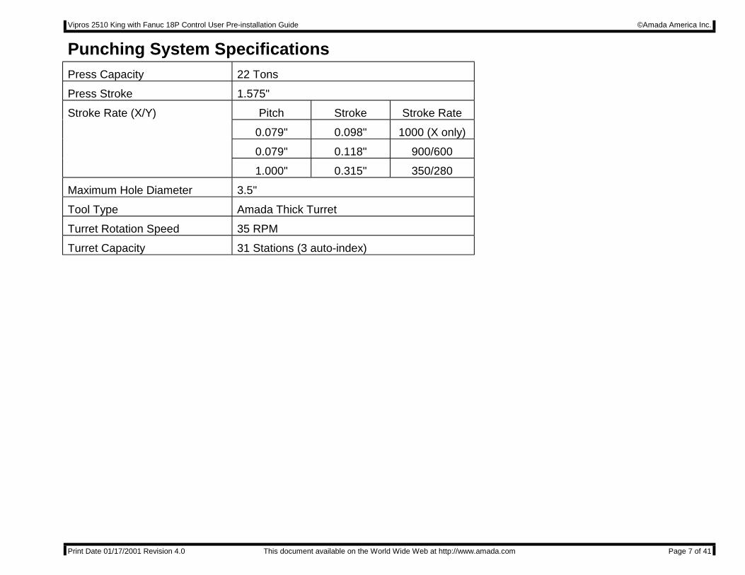
Punching System SpecificationsPress Capacity 22 Tons
Press Stroke 1.575"
Stroke Rate (X/Y) Pitch Stroke Stroke Rate
0.079" 0.098" 1000 (X only)
0.079" 0.118" 900/600
1.000" 0.315" 350/280
Maximum Hole Diameter 3.5"
Tool Type Amada Thick Turret
Turret Rotation Speed 35 RPM
Turret Capacity 31 Stations (3 auto-index)
Vipros 2510 King with Fanuc 18P Control User Pre-installation Guide ©Amada America Inc.
Print Date 01/17/2001 Revision 4.0 This document available on the World Wide Web at http://www.amada.com Page 8 of 41
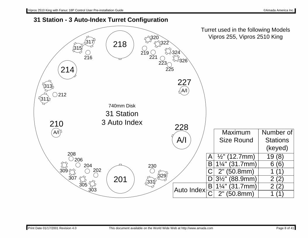
31 Station - 3 Auto-Index Turret Configuration
201202
303
204
305
206
307
208
309
210A/I
311212
313
214
218315
216
317320
219221
223225
A/I
326
324
322
227
A/I
331329
230
228
740mm Disk
31 Station3 Auto Index
ABCDBC
1¼" (31.7mm)2" (50.8mm)
3½" (88.9mm)1¼" (31.7mm)2" (50.8mm)
19 (8)
MaximumSize Round
Number ofStations(keyed)
Auto Index
½" (12.7mm)6 (6)1 (1)2 (2)2 (2)1 (1)
Turret used in the following ModelsVipros 255, Vipros 2510 King
Vipros 2510 King with Fanuc 18P Control User Pre-installation Guide ©Amada America Inc.
Print Date 01/17/2001 Revision 4.0 This document available on the World Wide Web at http://www.amada.com Page 9 of 41
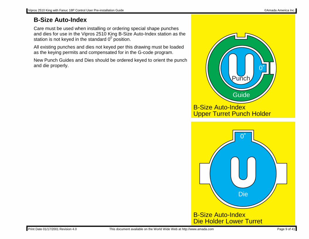
B-Size Auto-IndexCare must be used when installing or ordering special shape punchesand dies for use in the Vipros 2510 King B-Size Auto-Index station as thestation is not keyed in the standard 00 position.
All existing punches and dies not keyed per this drawing must be loadedas the keying permits and compensated for in the G-code program.
New Punch Guides and Dies should be ordered keyed to orient the punchand die properly.
B-Size Auto-IndexDie Holder Lower Turret
B-Size Auto-IndexUpper Turret Punch Holder
Punch
Guide
Die
0˚
0˚
Vipros 2510 King with Fanuc 18P Control User Pre-installation Guide ©Amada America Inc.
Print Date 01/17/2001 Revision 4.0 This document available on the World Wide Web at http://www.amada.com Page 10 of 41
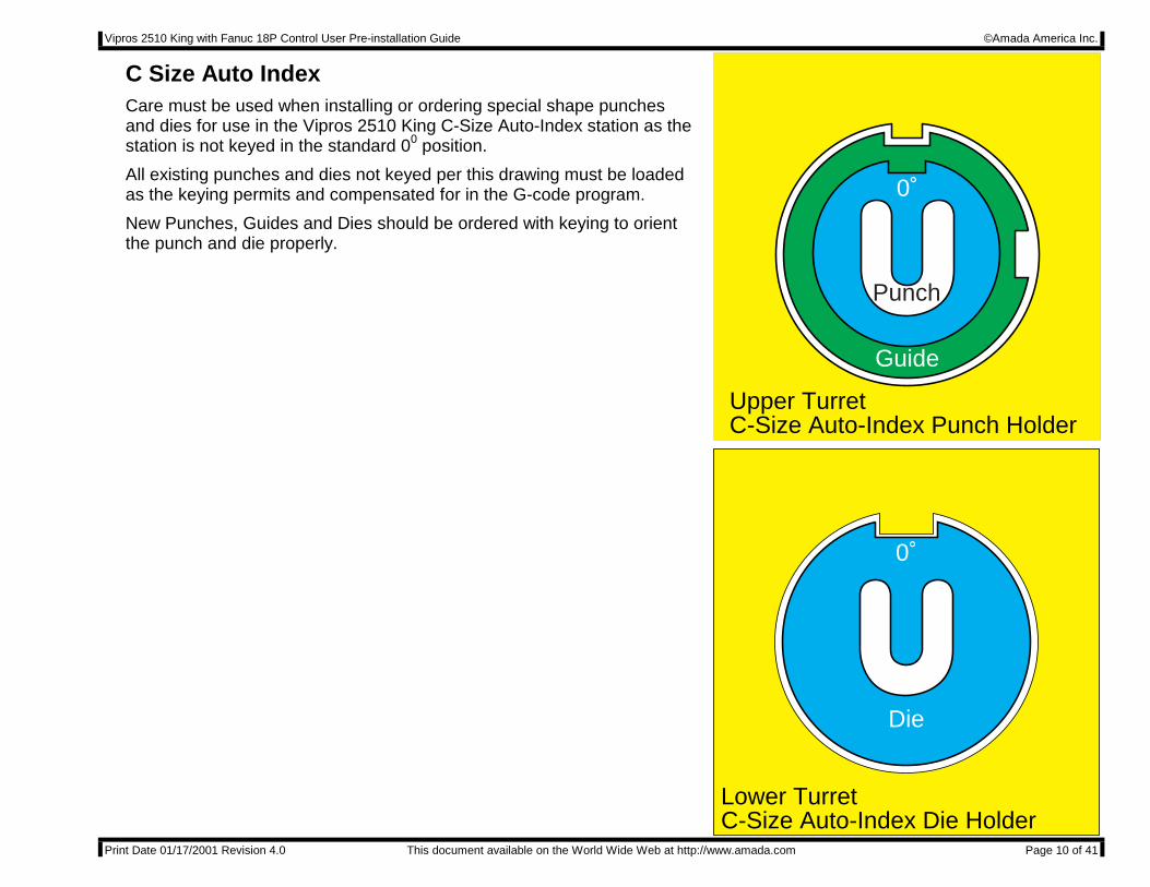
C Size Auto IndexCare must be used when installing or ordering special shape punchesand dies for use in the Vipros 2510 King C-Size Auto-Index station as thestation is not keyed in the standard 00 position.
All existing punches and dies not keyed per this drawing must be loadedas the keying permits and compensated for in the G-code program.
New Punches, Guides and Dies should be ordered with keying to orientthe punch and die properly.
Lower TurretC-Size Auto-Index Die Holder
Upper Turret C-Size Auto-Index Punch Holder
Punch
Guide
Die
0˚
0˚
Vipros 2510 King with Fanuc 18P Control User Pre-installation Guide ©Amada America Inc.
Print Date 01/17/2001 Revision 4.0 This document available on the World Wide Web at http://www.amada.com Page 11 of 41
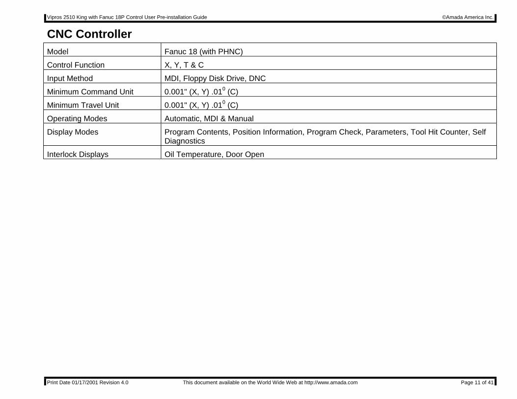
CNC ControllerModel Fanuc 18 (with PHNC)
Control Function X, Y, T & C
Input Method MDI, Floppy Disk Drive, DNC
Minimum Command Unit 0.001" (X, Y) .010 (C)
Minimum Travel Unit 0.001" (X, Y) .010 (C)
Operating Modes Automatic, MDI & Manual
Display Modes Program Contents, Position Information, Program Check, Parameters, Tool Hit Counter, SelfDiagnostics
Interlock Displays Oil Temperature, Door Open
Vipros 2510 King with Fanuc 18P Control User Pre-installation Guide ©Amada America Inc.
Print Date 01/17/2001 Revision 4.0 This document available on the World Wide Web at http://www.amada.com Page 12 of 41
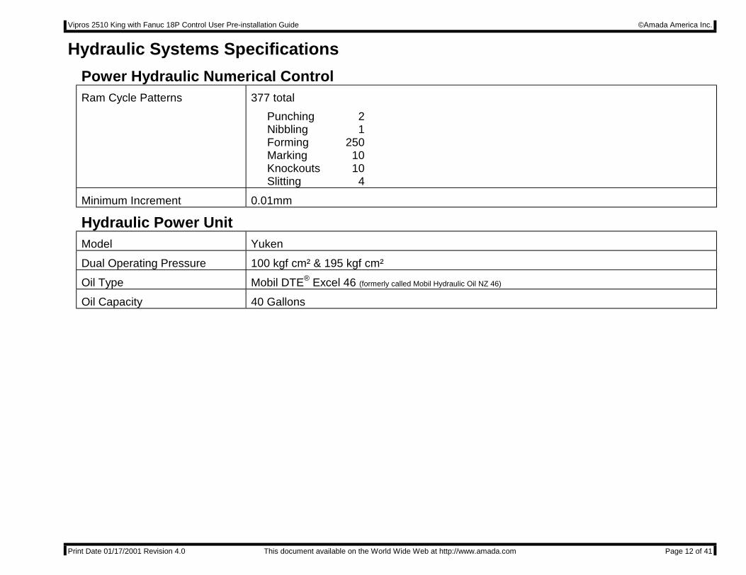
Hydraulic Systems Specifications
Power Hydraulic Numerical ControlRam Cycle Patterns 377 total
Punching 2Nibbling 1Forming 250Marking 10Knockouts 10Slitting 4
Minimum Increment 0.01mm
Hydraulic Power UnitModel Yuken
Dual Operating Pressure 100 kgf cm² & 195 kgf cm²
Oil Type Mobil DTE® Excel 46 (formerly called Mobil Hydraulic Oil NZ 46)
Oil Capacity 40 Gallons

Vipros 2510 King with Fanuc 18P Control User Pre-installation Guide ©Amada America Inc.
Print Date 01/17/2001 Revision 4.0 This document available on the World Wide Web at http://www.amada.com Page 13 of 41
Electrical RequirementsVipros 2510 King 230 / 460 / 3 / 60 ±10%, 22 kVA
56 amps @ 230 / 3 / 60 VAC*28 amps @ 460 / 3 / 60 VAC*
SBC EX 3.0 Chiller
The Chiller voltage must be specifiedwhen machine is ordered
230 or 460 / 3 / 60 ±10%, 15 kVA38 amps @ 230 / 3 / 60 VAC*19 amps @ 460 / 3 / 60 VAC*
Optional EquipmentV255hs Conveyor 208 / 230 / 460 3ph ±10%, kVA
2.1 amps @ 208 / 3/ 60 VAC*2.0 amps @ 230 / 3 / 60 VAC*1.0 amps @ 460 / 3 / 60 VAC*
MP1225 Loader 200 / 3 / 60 ±10%, 10 kVA29 amps @ 200 / 3 / 60 VAC*
To operate at 230 / 460 VAC a step up transformer with the following service isrequired
26 amps @ 230 / 3 / 60 VAC*13 amps @ 460 / 3 / 60 VAC*
*This is actual maximum current draw of the machinery. The actual supplied electrical service must be sized to allow forstarting current of approximately 150% of this value.
Vipros 2510 King with Fanuc 18P Control User Pre-installation Guide ©Amada America Inc.
Print Date 01/17/2001 Revision 4.0 This document available on the World Wide Web at http://www.amada.com Page 14 of 41
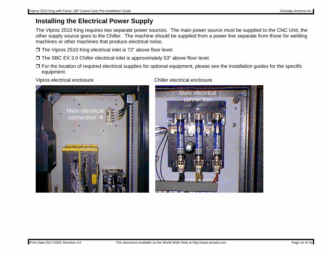
Installing the Electrical Power SupplyThe Vipros 2510 King requires two separate power sources. The main power source must be supplied to the CNC Unit, theother supply source goes to the Chiller. The machine should be supplied from a power line separate from those for weldingmachines or other machines that produce electrical noise.
! The Vipros 2510 King electrical inlet is 72" above floor level.
! The SBC EX 3.0 Chiller electrical inlet is approximately 53" above floor level.
! For the location of required electrical supplies for optional equipment, please see the installation guides for the specificequipment.
Vipros electrical enclosure Chiller electrical enclosure
Main electricalconnection #
Main electricalconnection
$
Vipros 2510 King with Fanuc 18P Control User Pre-installation Guide ©Amada America Inc.
Print Date 01/17/2001 Revision 4.0 This document available on the World Wide Web at http://www.amada.com Page 15 of 41
Pneumatic RequirementsVipros 2510 King 80 psi @ 8.8 ft3/min.
Optional EquipmentNJMP1225 Loader 75 psi @ 31.8 ft3/min.
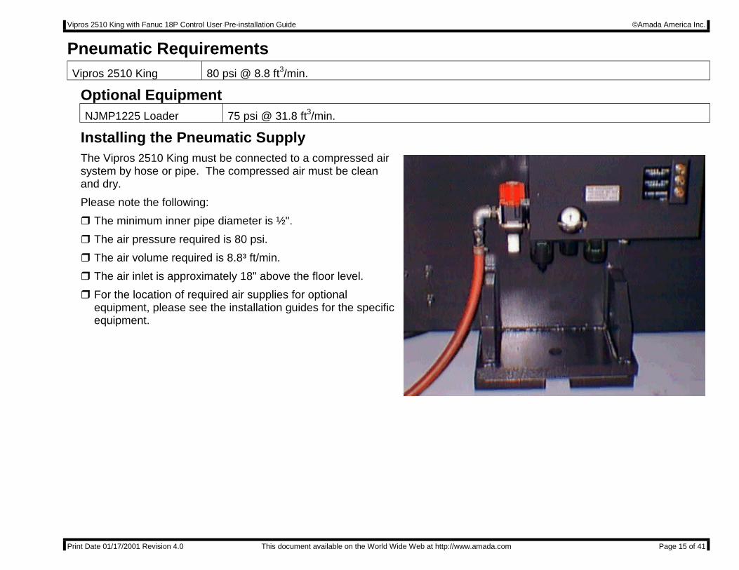
Installing the Pneumatic SupplyThe Vipros 2510 King must be connected to a compressed airsystem by hose or pipe. The compressed air must be cleanand dry.
Please note the following:
! The minimum inner pipe diameter is ½".
! The air pressure required is 80 psi.
! The air volume required is 8.8³ ft/min.
! The air inlet is approximately 18" above the floor level.
! For the location of required air supplies for optionalequipment, please see the installation guides for the specificequipment.
Vipros 2510 King with Fanuc 18P Control User Pre-installation Guide ©Amada America Inc.
Print Date 01/17/2001 Revision 4.0 This document available on the World Wide Web at http://www.amada.com Page 16 of 41
Planning the Location of the Vipros 2510 KingThe following diagrams provide the details for positioning your new Vipros 2510 King.
" No obstacles are allowed in the worksheet travel area and the ceiling must be at least 40" above the top of the Vipros 2510King.
" All of the recommended Safety / Maintenance areas should be used, but at a minimum, the doors of Fanuc 18P Control unitmust be able to be opened. Any reduction of the listed Safety / Maintenance areas may decrease personnel safety andincrease time and expense of installation and maintenance.
" The Vipros 2510 King and Fanuc 18P Control must be protected from direct sunlight or other heat sources. Exposure todirect heating sources such as infrared heaters have been shown to affect punch and die alignment.
" The positioning of the SBC EX 3.0 Chiller is very flexible. Please see Chiller page 22 of this document.
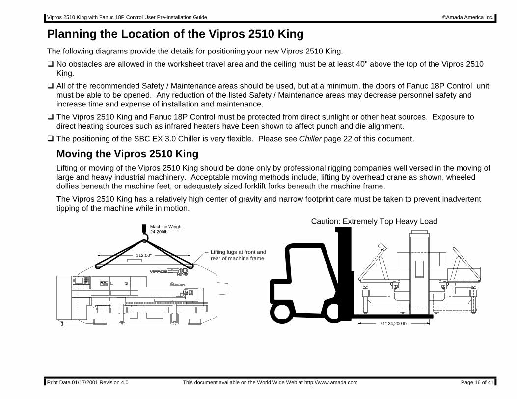
Moving the Vipros 2510 KingLifting or moving of the Vipros 2510 King should be done only by professional rigging companies well versed in the moving oflarge and heavy industrial machinery. Acceptable moving methods include, lifting by overhead crane as shown, wheeleddollies beneath the machine feet, or adequately sized forklift forks beneath the machine frame.
The Vipros 2510 King has a relatively high center of gravity and narrow footprint care must be taken to prevent inadvertenttipping of the machine while in motion.
Machine Weight24,200lb.
Lifting lugs at front and rear of machine frame
112.00"
71" 24,200 lb.
Caution: Extremely Top Heavy Load
Vipros 2510 King with Fanuc 18P Control User Pre-installation Guide ©Amada America Inc.
Print Date 01/17/2001 Revision 4.0 This document available on the World Wide Web at http://www.amada.com Page 17 of 41
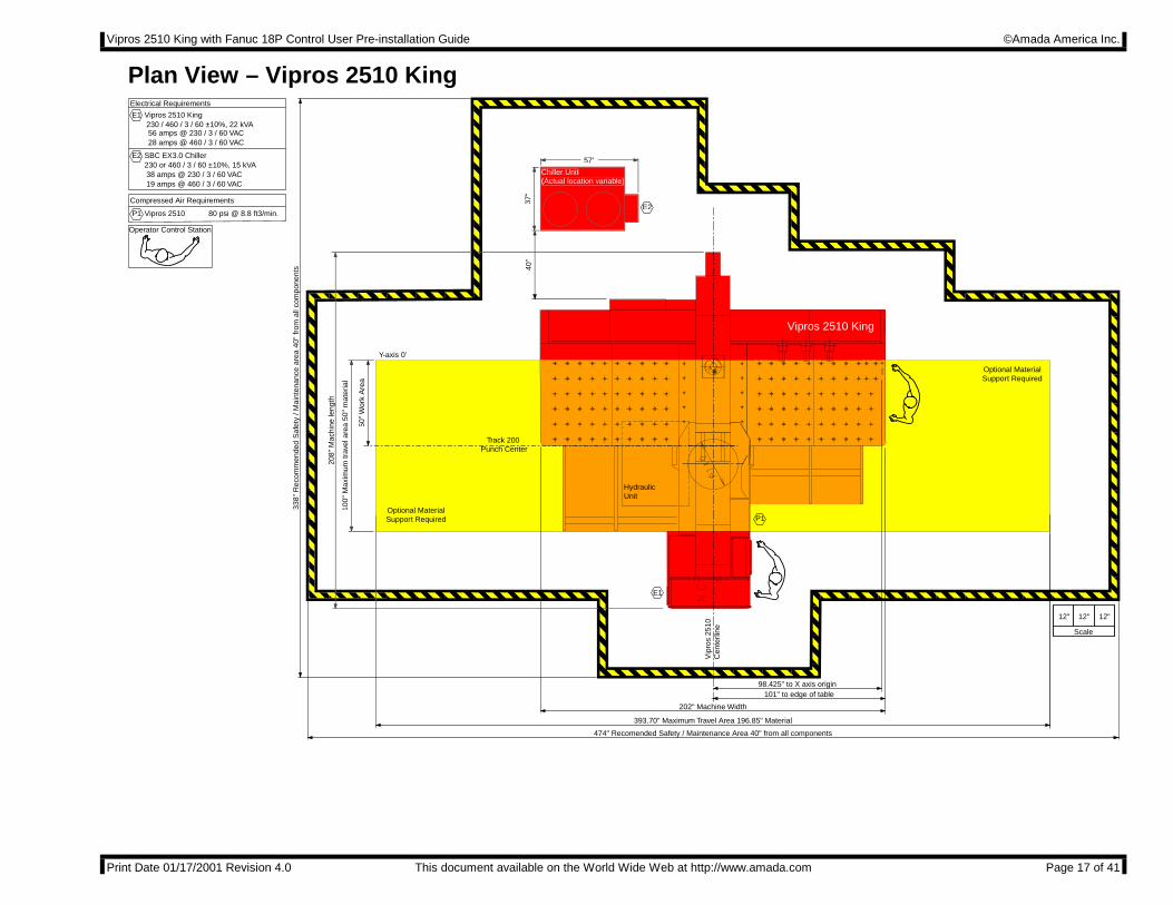
Plan View – Vipros 2510 King
338"
Rec
omm
ende
d S
afet
y / M
aint
enan
ce a
rea
40"
from
all
com
pone
nts
100"
Max
imum
trav
el a
rea
50"
mat
eria
l
50"
Wor
k A
rea
Optional MaterialSupport Required
Optional MaterialSupport Required
393.70" Maximum Travel Area 196.85" Material
Chiller Unit(Actual location variable)
HydraulicUnit
98.425" to X axis origin
40"
37"
57"
Y-axis 0"
Track 200 Punch Center
101" to edge of table
202" Machine Width
208"
Mac
hine
leng
th
E1
E22
P1
Vipros 2510 King
12" 12" 12"
Scale
Electrical Requirements
Vipros 2510 King
Vipros 2510
Compressed Air Requirements
230 / 460 / 3 / 60 ±10%, 22 kVA
SBC EX3.0 Chiller230 or 460 / 3 / 60 ±10%, 15 kVA
80 psi @ 8.8 ft3/min.
56 amps @ 230 / 3 / 60 VAC28 amps @ 460 / 3 / 60 VAC
38 amps @ 230 / 3 / 60 VAC19 amps @ 460 / 3 / 60 VAC
E1
E2
P1
Vip
ros
2510
Cen
terli
ne
Operator Control Station
474" Recomended Safety / Maintenance Area 40" from all components
Vipros 2510 King with Fanuc 18P Control User Pre-installation Guide ©Amada America Inc.
Print Date 01/17/2001 Revision 4.0 This document available on the World Wide Web at http://www.amada.com Page 18 of 41
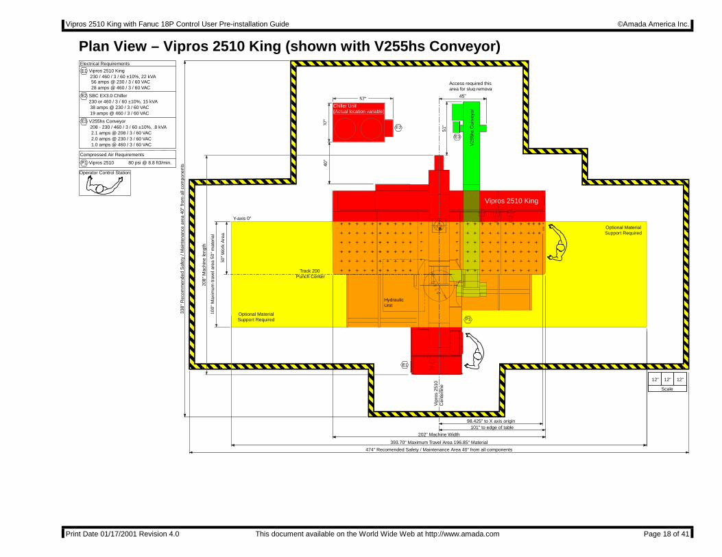
Plan View – Vipros 2510 King (shown with V255hs Conveyor)
338"
Rec
omm
ende
d S
afet
y / M
aint
enan
ce a
rea
40"
from
all
com
pone
nts
Access required thisarea for slug removal
V25
5hs
Con
veyo
r
E33
45"
51"
100"
Max
imum
trav
el a
rea
50"
mat
eria
l
50"
Wor
k A
rea
Optional MaterialSupport Required
Optional MaterialSupport Required
393.70" Maximum Travel Area 196.85" Material
Chiller Unit(Actual location variable)
HydraulicUnit
98.425" to X axis origin
40"
37"
57"
Y-axis 0"
Track 200 Punch Center
101" to edge of table
202" Machine Width
208"
Mac
hine
leng
th
E1
E22
P1
Vipros 2510 King
12" 12" 12"
Scale
Electrical Requirements
Vipros 2510 King
Vipros 2510
V255hs Conveyor
Compressed Air Requirements
230 / 460 / 3 / 60 ±10%, 22 kVA
SBC EX3.0 Chiller230 or 460 / 3 / 60 ±10%, 15 kVA
208 - 230 / 460 / 3 / 60 ±10%, .8 kVA
80 psi @ 8.8 ft3/min.
56 amps @ 230 / 3 / 60 VAC28 amps @ 460 / 3 / 60 VAC
38 amps @ 230 / 3 / 60 VAC19 amps @ 460 / 3 / 60 VAC
2.1 amps @ 208 / 3 / 60 VAC2.0 amps @ 230 / 3 / 60 VAC1.0 amps @ 460 / 3 / 60 VAC
E1
E2
E3
P1
Vip
ros
2510
Cen
terli
ne
Operator Control Station
474" Recomended Safety / Maintenance Area 40" from all components

Vipros 2510 King with Fanuc 18P Control User Pre-installation Guide ©Amada America Inc.
Print Date 01/17/2001 Revision 4.0 This document available on the World Wide Web at http://www.amada.com Page 19 of 41
Plan View – Vipros 2510 King (shown with V255hs Conveyor and MP1225 Loader)
338"
Rec
omm
ende
d S
afet
y / M
aint
enan
ce a
rea
40"
from
all
com
pone
nts
520" Recomended Safety / Maintenance Area 40" from all components
MP1225 Loader
Access for material loading / unloading
required in this area
XformerMP1225
68"
122"
190"
Loa
der
Leng
th
244" to edge of Loader
142" Loader Width
E4
P2
344" Vipros 2510 King MP1225 assembly width
Access required thisarea for slug removal
V25
5hs
Con
veyo
r
E33
45"
51"
100"
Max
imum
trav
el a
rea
50"
mat
eria
l
50"
Wor
k A
rea
Optional MaterialSupport Required
Optional MaterialSupport Required
393.70" Maximum Travel Area 196.85" Material
Chiller Unit(Actual location variable)
HydraulicUnit
98.425" to X axis origin
40"
37"
57"
Y-axis 0"
Track 200 Punch Center
101" to edge of table
202" Machine Width
102" to edge of Loader
208"
Mac
hine
leng
th
E1
E22
P1
Vipros 2510 King
12" 12" 12"
Scale
Electrical Requirements
Vipros 2510 King
Vipros 2510
V255hs Conveyor
MP1225 Loader
MP1225 Loader
Compressed Air Requirements
230 / 460 / 3 / 60 ±10%, 22 kVA
SBC EX3.0 Chiller230 or 460 / 3 / 60 ±10%, 15 kVA
208 - 230 / 460 / 3 / 60 ±10%, .8 kVA
80 psi @ 8.8 ft3/min.
75 psi @ 31.8 ft3/min.
56 amps @ 230 / 3 / 60 VAC28 amps @ 460 / 3 / 60 VAC
38 amps @ 230 / 3 / 60 VAC19 amps @ 460 / 3 / 60 VAC
2.1 amps @ 208 / 3 / 60 VAC2.0 amps @ 230 / 3 / 60 VAC1.0 amps @ 460 / 3 / 60 VAC
29 amps @ 200 / 3 / 60 VAC
200 / 3 / 60 ±10%, 10 KvaTo operate at 230 / 460 VAC a step up transformer is required with the following service is required
26 amps @ 230 / 3 / 60 VAC13 amps @ 460 / 3 / 60 VAC
E1
E2
E3
E4
P1
P2
Vip
ros
2510
Cen
terli
ne
Operator Control Station
Vipros 2510 King with Fanuc 18P Control User Pre-installation Guide ©Amada America Inc.
Print Date 01/17/2001 Revision 4.0 This document available on the World Wide Web at http://www.amada.com Page 20 of 41
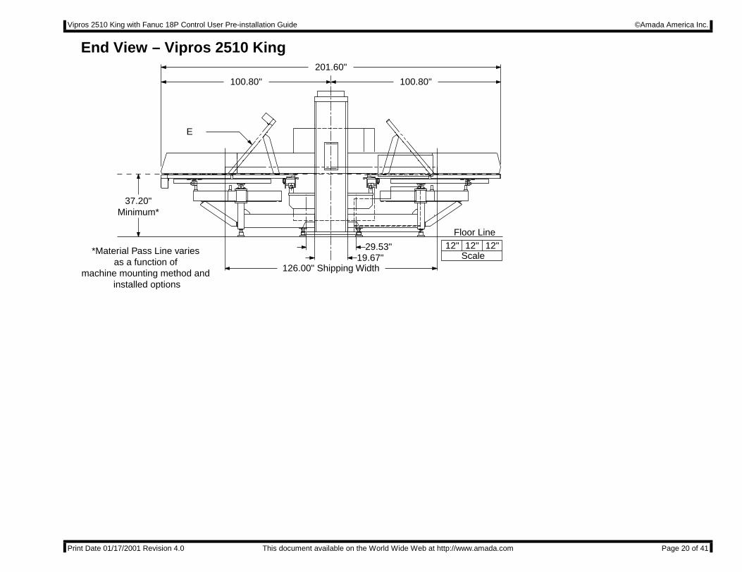
End View – Vipros 2510 King
Floor Line
37.20"Minimum*
126.00" Shipping Width19.67"
29.53"
201.60"
100.80"100.80"
12" 12"12"Scale*Material Pass Line varies
as a function of machine mounting method and
installed options
E
Vipros 2510 King with Fanuc 18P Control User Pre-installation Guide ©Amada America Inc.
Print Date 01/17/2001 Revision 4.0 This document available on the World Wide Web at http://www.amada.com Page 21 of 41
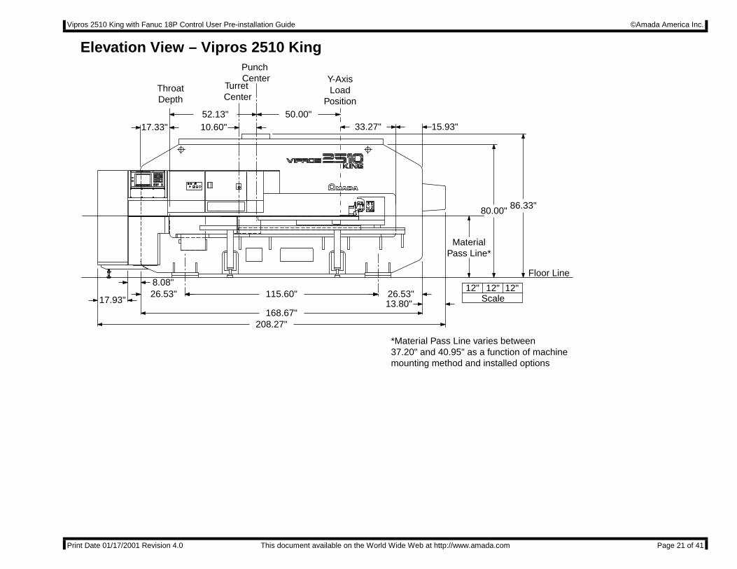
Elevation View – Vipros 2510 KingPunch Center
ThroatDepth
Y-AxisLoad
Position
15.93"33.27"50.00"
10.60"52.13"
17.33"
86.33"80.00"
MaterialPass Line*
8.08"
13.80"26.53"
17.93"26.53"
208.27"168.67"
115.60"
Turret Center
12" 12"12"Scale
Floor Line
*Material Pass Line varies between 37.20" and 40.95" as a function of machine mounting method and installed options
Vipros 2510 King with Fanuc 18P Control User Pre-installation Guide ©Amada America Inc.
Print Date 01/17/2001 Revision 4.0 This document available on the World Wide Web at http://www.amada.com Page 22 of 41
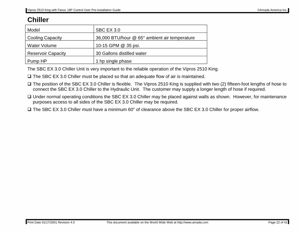
ChillerModel SBC EX 3.0
Cooling Capacity 36,000 BTU/hour @ 65° ambient air temperature
Water Volume 10-15 GPM @ 35 psi.
Reservoir Capacity 30 Gallons distilled water
Pump HP 1 hp single phase
The SBC EX 3.0 Chiller Unit is very important to the reliable operation of the Vipros 2510 King.
" The SBC EX 3.0 Chiller must be placed so that an adequate flow of air is maintained.
" The position of the SBC EX 3.0 Chiller is flexible. The Vipros 2510 King is supplied with two (2) fifteen-foot lengths of hose toconnect the SBC EX 3.0 Chiller to the Hydraulic Unit. The customer may supply a longer length of hose if required.
" Under normal operating conditions the SBC EX 3.0 Chiller may be placed against walls as shown. However, for maintenancepurposes access to all sides of the SBC EX 3.0 Chiller may be required.
" The SBC EX 3.0 Chiller must have a minimum 60" of clearance above the SBC EX 3.0 Chiller for proper airflow.
Vipros 2510 King with Fanuc 18P Control User Pre-installation Guide ©Amada America Inc.
Print Date 01/17/2001 Revision 4.0 This document available on the World Wide Web at http://www.amada.com Page 23 of 41
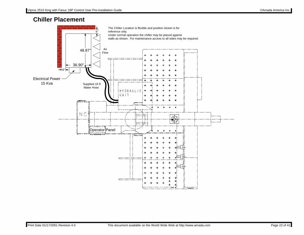
Chiller Placement
Operator Panel
Electrical Power15 Kva
48.87"
36.90"
AirFlow
6"
6"The Chiller Location is flexible and position shown is forreference only.Under normal operation the chiller may be placed againstwalls as shown. For maintenance access to all sides may be required.
Supplied 15 ft Water Hose
Vipros 2510 King with Fanuc 18P Control User Pre-installation Guide ©Amada America Inc.
Print Date 01/17/2001 Revision 4.0 This document available on the World Wide Web at http://www.amada.com Page 24 of 41
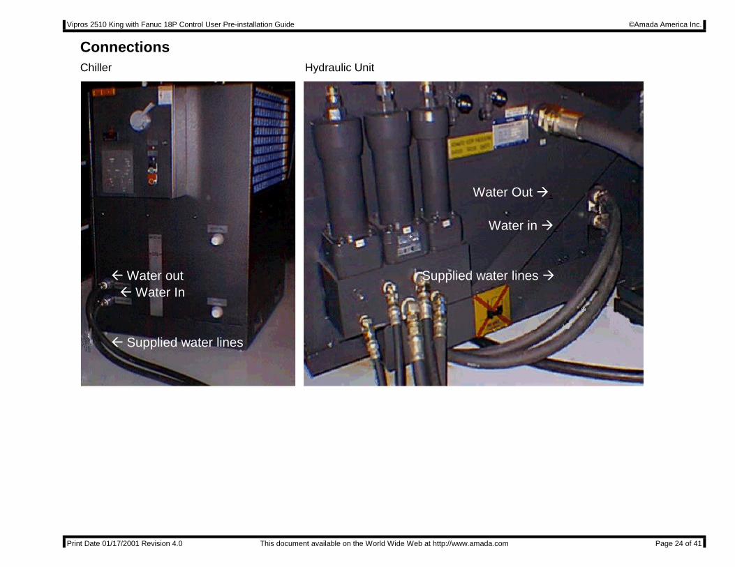
ConnectionsChiller Hydraulic Unit
Water Out #.
% Water out% Water In
Water in #.
% Supplied water lines
Supplied water lines #

Vipros 2510 King with Fanuc 18P Control User Pre-installation Guide ©Amada America Inc.
Print Date 01/17/2001 Revision 4.0 This document available on the World Wide Web at http://www.amada.com Page 25 of 41
Foundation RequirementsThe Vipros 2510 King does not require a special foundation to perform as expected, however there are minimum requirementsthat an existing floor must meet in order to assure machine reliability and tool life. If the existing floor does not meet thefollowing minimum requirements, plans for a recommended foundation are given in the section Foundation Anchoring Procedure
The minimum acceptable floor conditions to assure a successful installation are:
" The area of the floor where the Vipros 2510 King frame is to be located must be a single, homogeneous slab in goodcondition. There must be no cracks or other signs of deterioration of the floor.
" The floor must be 4" to 6" thick.
" The floor must be capable of supporting 3.5 tons/ft².
" The floor must be level to 0.032"/ft.
If the existing floor meets the minimum requirement list above, it must still be inspected carefully when the anchor-bolt holes arecut. Voids under the floor, or wetness (not associated with the hole cutting procedure) should be considered signs of aninadequate floor and a new machine location or new foundation must be considered.
It is the customer’s responsibility to determine that the floor meets these minimum requirements. Placing the machine on aninadequate, cracked floor, or straddling seams in a floor may be grounds for voiding the machine warranty!
Amada America Inc. does not recommend the use of vibration isolating mounts under the machine feet, as these devices havebeen shown to increase the vibration within the machine frame, increasing the likelihood of vibration related problems. Solidleveling devices are acceptable provided they incorporate a means of anchoring the machine to the floor with the supplied J-bolts or alternative anchoring method.
Special Note: This document details several methods of anchoring the Vipros 2510 King to a new foundation or anexisting floor. These methods are designed to install the Vipros 2510 King as a stand-alone machine usingthe supplied anchor bolts and base plates. Installation or use of additional options such as leveling pads ormaterial handling systems may dictate other methods of anchoring or foundation design not shown in thisdocument. Before committing to a specific method of anchoring the Vipros 2510 King, confirm that thechosen method is compatible with all purchased optional items and planned expansion.
Vipros 2510 King with Fanuc 18P Control User Pre-installation Guide ©Amada America Inc.
Print Date 01/17/2001 Revision 4.0 This document available on the World Wide Web at http://www.amada.com Page 26 of 41
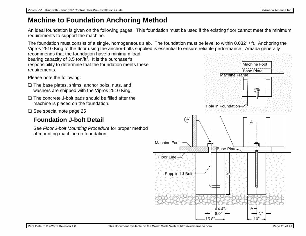
Machine to Foundation Anchoring MethodAn ideal foundation is given on the following pages. This foundation must be used if the existing floor cannot meet the minimumrequirements to support the machine.
The foundation must consist of a single, homogeneous slab. The foundation must be level to within 0.032" / ft. Anchoring theVipros 2510 King to the floor using the anchor-bolts supplied is essential to ensure reliable performance. Amada generallyrecommends that the foundation have a minimum loadbearing capacity of 3.5 ton/ft2. It is the purchaser’sresponsibility to determine that the foundation meets theserequirements.
Please note the following:
" The base plates, shims, anchor bolts, nuts, andwashers are shipped with the Vipros 2510 King.
" The concrete J-bolt pads should be filled after themachine is placed on the foundation.
" See special note page 25
Foundation J-bolt DetailSee Floor J-bolt Mounting Procedure for proper methodof mounting machine on foundation.
5"
10"15.8"
Base Plate
Hole in Foundation
Floor Line
Machine Foot
A
A
A
Machine Frame
Machine Foot
Base Plate
Supplied J-Bolt
4.4"8.0"
24"
Vipros 2510 King with Fanuc 18P Control User Pre-installation Guide ©Amada America Inc.
Print Date 01/17/2001 Revision 4.0 This document available on the World Wide Web at http://www.amada.com Page 27 of 41
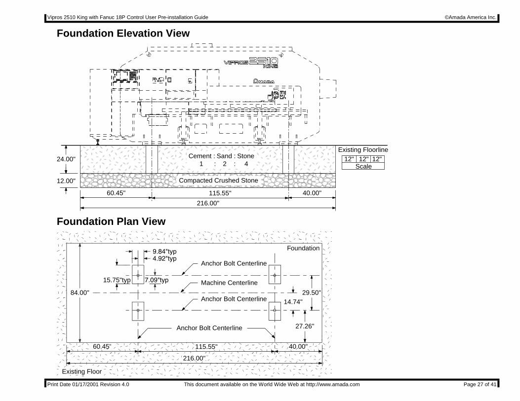
Foundation Elevation View
24.00"
12.00"
216.00"
60.45" 40.00"115.55"
Existing Floorline12" 12"12"
Scale
Compacted Crushed Stone
Cement : Sand : Stone 1 : 2 : 4
Foundation Plan View
Anchor Bolt Centerline
Anchor Bolt Centerline
Anchor Bolt Centerline
Machine Centerline15.75"typ
84.00" 29.50"14.74"
27.26"
216.00"
60.450 560.45" 40.00"115.55"
Foundation
Existing Floor
Vipros 2510 King with Fanuc 18P Control User Pre-installation Guide ©Amada America Inc.
Print Date 01/17/2001 Revision 4.0 This document available on the World Wide Web at http://www.amada.com Page 28 of 41
5"
10"15.8"
Base Plate
Saw Cut Hole InExisting Floor
Floor Line
Machine Foot
A
A
A
Machine Frame
Machine Foot
Base Plate
Supplied J-Bolt
4.4"8.0"
24"
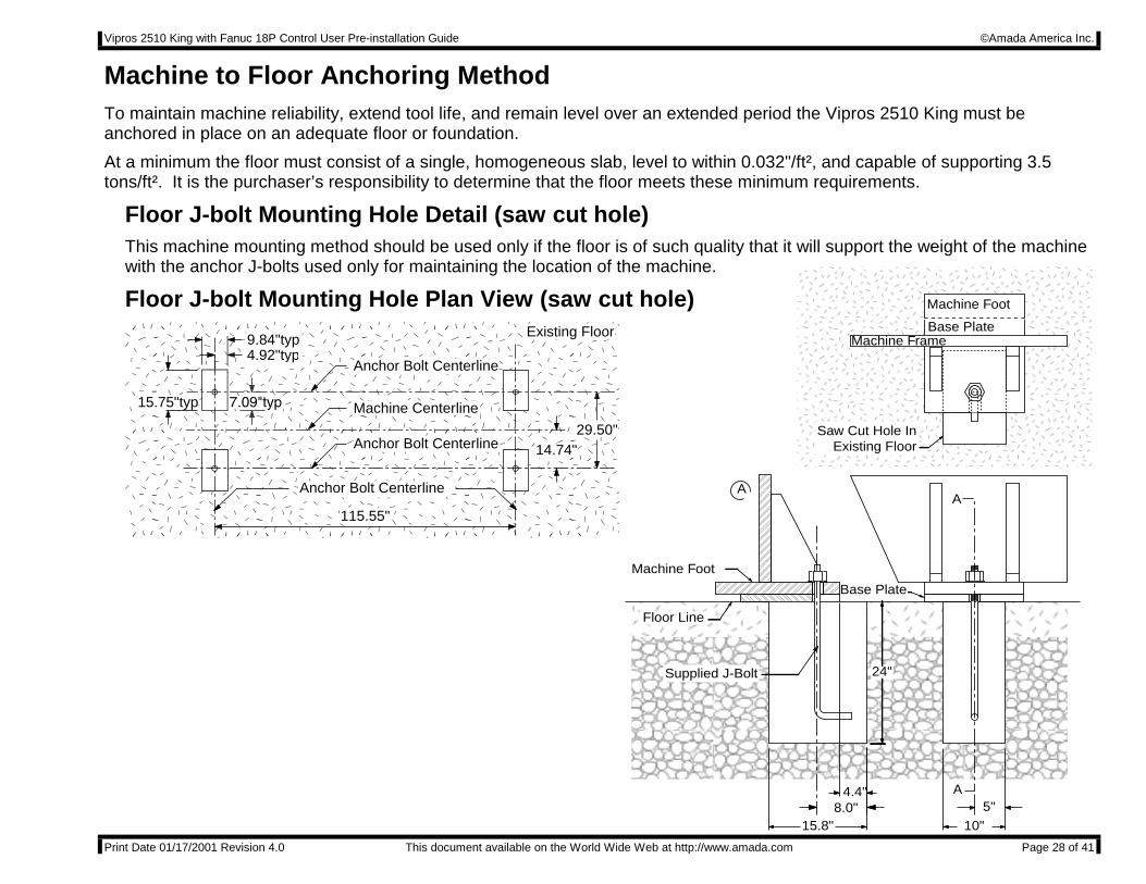
Machine to Floor Anchoring MethodTo maintain machine reliability, extend tool life, and remain level over an extended period the Vipros 2510 King must beanchored in place on an adequate floor or foundation.
At a minimum the floor must consist of a single, homogeneous slab, level to within 0.032"/ft², and capable of supporting 3.5tons/ft². It is the purchaser’s responsibility to determine that the floor meets these minimum requirements.
Floor J-bolt Mounting Hole Detail (saw cut hole)This machine mounting method should be used only if the floor is of such quality that it will support the weight of the machinewith the anchor J-bolts used only for maintaining the location of the machine.
Floor J-bolt Mounting Hole Plan View (saw cut hole)
Anchor Bolt Centerline
Anchor Bolt Centerline
Anchor Bolt Centerline
Machine Centerline15.75"typ
4.92"typ9.84"typ
29.50"14.74"
115.55"
Existing Floor
Vipros 2510 King with Fanuc 18P Control User Pre-installation Guide ©Amada America Inc.
Print Date 01/17/2001 Revision 4.0 This document available on the World Wide Web at http://www.amada.com Page 29 of 41
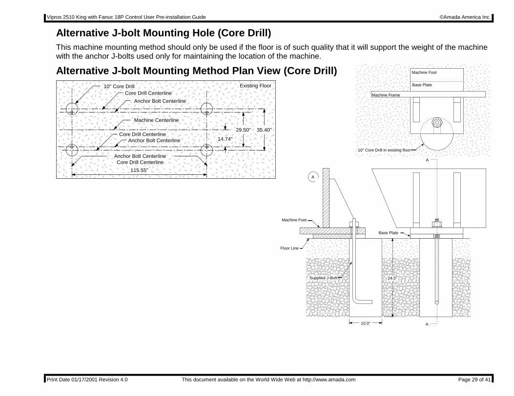
10.0"
24.0"
Base Plate
10" Core Drill in existing floor
Floor Line
Machine Foot
A
A
A
Machine Frame
Machine Foot
Base Plate
Supplied J-Bolt
Alternative J-bolt Mounting Hole (Core Drill)This machine mounting method should only be used if the floor is of such quality that it will support the weight of the machinewith the anchor J-bolts used only for maintaining the location of the machine.
Alternative J-bolt Mounting Method Plan View (Core Drill)10" Core Drill
35.40"
Core Drill Centerline
Anchor Bolt CenterlineCore Drill Centerline
Anchor Bolt Centerline
Anchor Bolt Centerline
Machine Centerline
29.50"
14.74"
115.55"
Existing Floor
Core Drill Centerline
Vipros 2510 King with Fanuc 18P Control User Pre-installation Guide ©Amada America Inc.
Print Date 01/17/2001 Revision 4.0 This document available on the World Wide Web at http://www.amada.com Page 30 of 41
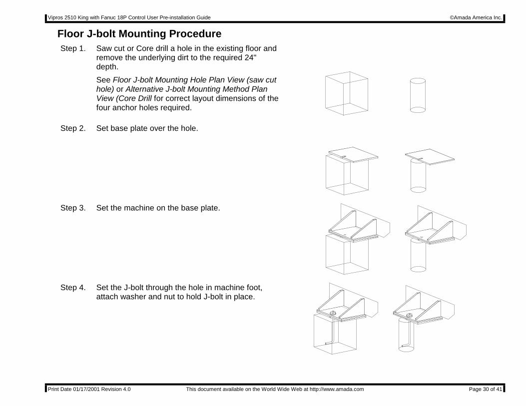
Floor J-bolt Mounting ProcedureStep 1. Saw cut or Core drill a hole in the existing floor and
remove the underlying dirt to the required 24"depth.
See Floor J-bolt Mounting Hole Plan View (saw cuthole) or Alternative J-bolt Mounting Method PlanView (Core Drill for correct layout dimensions of thefour anchor holes required.
Step 2. Set base plate over the hole.
Step 3. Set the machine on the base plate.
Step 4. Set the J-bolt through the hole in machine foot,attach washer and nut to hold J-bolt in place.
Vipros 2510 King with Fanuc 18P Control User Pre-installation Guide ©Amada America Inc.
Print Date 01/17/2001 Revision 4.0 This document available on the World Wide Web at http://www.amada.com Page 31 of 41
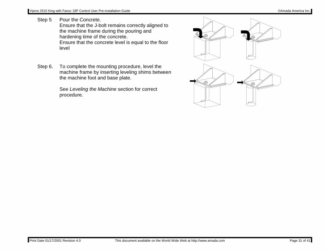
Step 5 Pour the Concrete.Ensure that the J-bolt remains correctly aligned tothe machine frame during the pouring andhardening time of the concrete.Ensure that the concrete level is equal to the floorlevel
Step 6. To complete the mounting procedure, level themachine frame by inserting leveling shims betweenthe machine foot and base plate.
See Leveling the Machine section for correctprocedure.
Vipros 2510 King with Fanuc 18P Control User Pre-installation Guide ©Amada America Inc.
Print Date 01/17/2001 Revision 4.0 This document available on the World Wide Web at http://www.amada.com Page 32 of 41
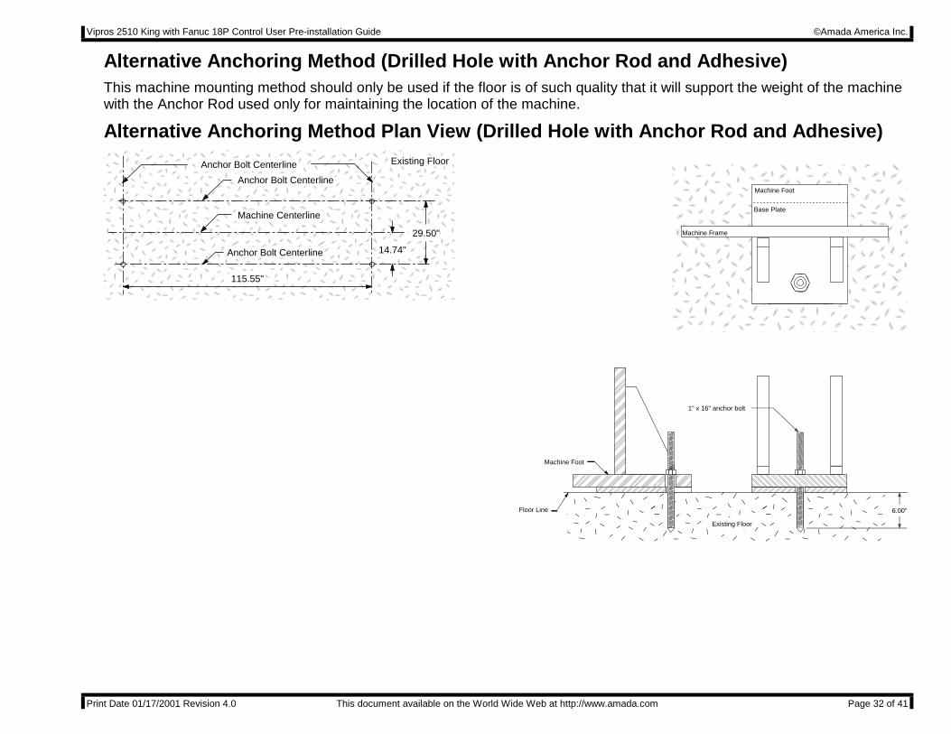
Alternative Anchoring Method (Drilled Hole with Anchor Rod and Adhesive)This machine mounting method should only be used if the floor is of such quality that it will support the weight of the machinewith the Anchor Rod used only for maintaining the location of the machine.
Alternative Anchoring Method Plan View (Drilled Hole with Anchor Rod and Adhesive)
Anchor Bolt Centerline
Anchor Bolt Centerline
Anchor Bolt Centerline
Machine Centerline
29.50"
14.74"
115.55"
Existing Floor
Floor Line
Machine Foot
Machine Frame
Machine Foot
1" x 16" anchor bolt
6.00"
Existing Floor
Base Plate
Vipros 2510 King with Fanuc 18P Control User Pre-installation Guide ©Amada America Inc.
Print Date 01/17/2001 Revision 4.0 This document available on the World Wide Web at http://www.amada.com Page 33 of 41
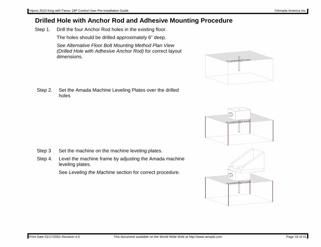
Drilled Hole with Anchor Rod and Adhesive Mounting ProcedureStep 1. Drill the four Anchor Rod holes in the existing floor.
The holes should be drilled approximately 6” deep.
See Alternative Floor Bolt Mounting Method Plan View(Drilled Hole with Adhesive Anchor Rod) for correct layoutdimensions.
Existing Floor
Step 2. Set the Amada Machine Leveling Plates over the drilledholes
Existing Floor
Step 3
Step 4.
Set the machine on the machine leveling plates.
Level the machine frame by adjusting the Amada machineleveling plates.
See Leveling the Machine section for correct procedure.
Existing Floor
Vipros 2510 King with Fanuc 18P Control User Pre-installation Guide ©Amada America Inc.
Print Date 01/17/2001 Revision 4.0 This document available on the World Wide Web at http://www.amada.com Page 34 of 41
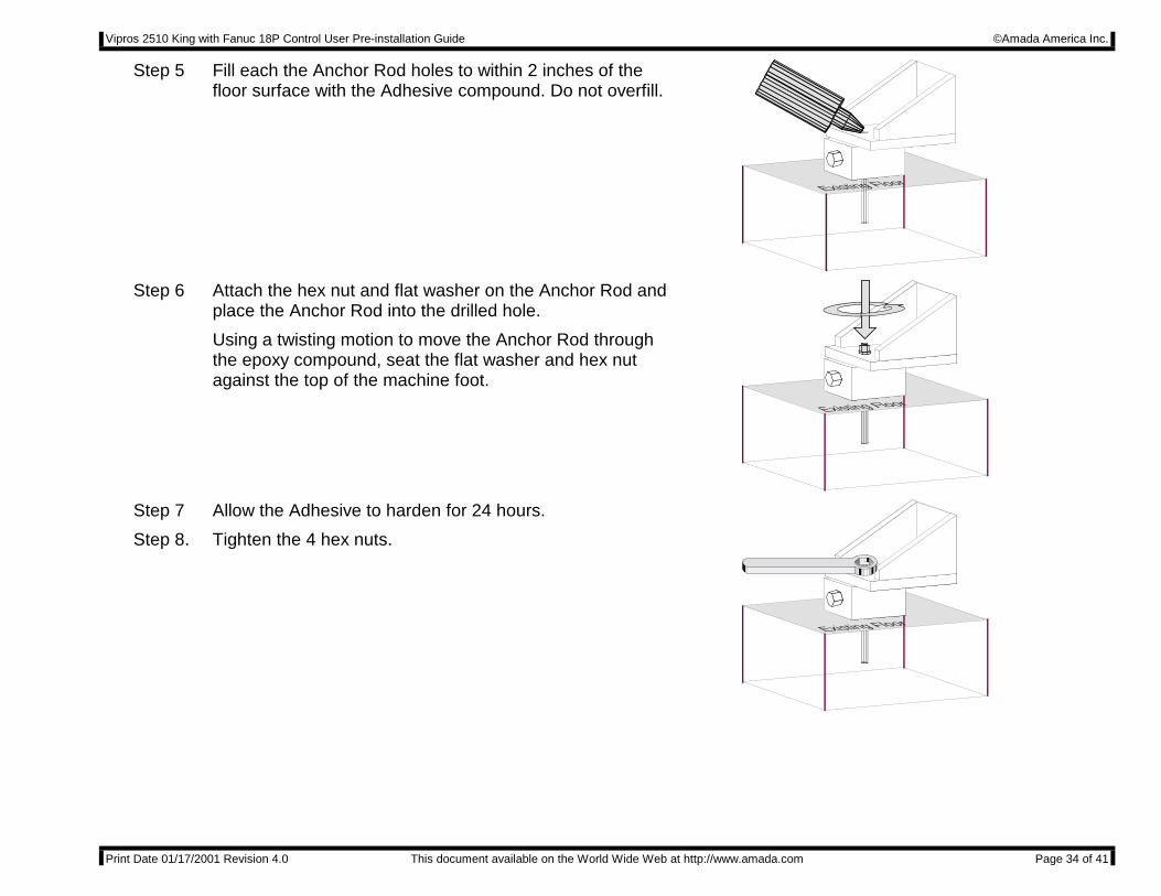
Step 5 Fill each the Anchor Rod holes to within 2 inches of thefloor surface with the Adhesive compound. Do not overfill.
Existing Floor
Step 6 Attach the hex nut and flat washer on the Anchor Rod andplace the Anchor Rod into the drilled hole.
Using a twisting motion to move the Anchor Rod throughthe epoxy compound, seat the flat washer and hex nutagainst the top of the machine foot.
Existing Floor
Step 7
Step 8.
Allow the Adhesive to harden for 24 hours.
Tighten the 4 hex nuts.
Existing Floor
Vipros 2510 King with Fanuc 18P Control User Pre-installation Guide ©Amada America Inc.
Print Date 01/17/2001 Revision 4.0 This document available on the World Wide Web at http://www.amada.com Page 35 of 41
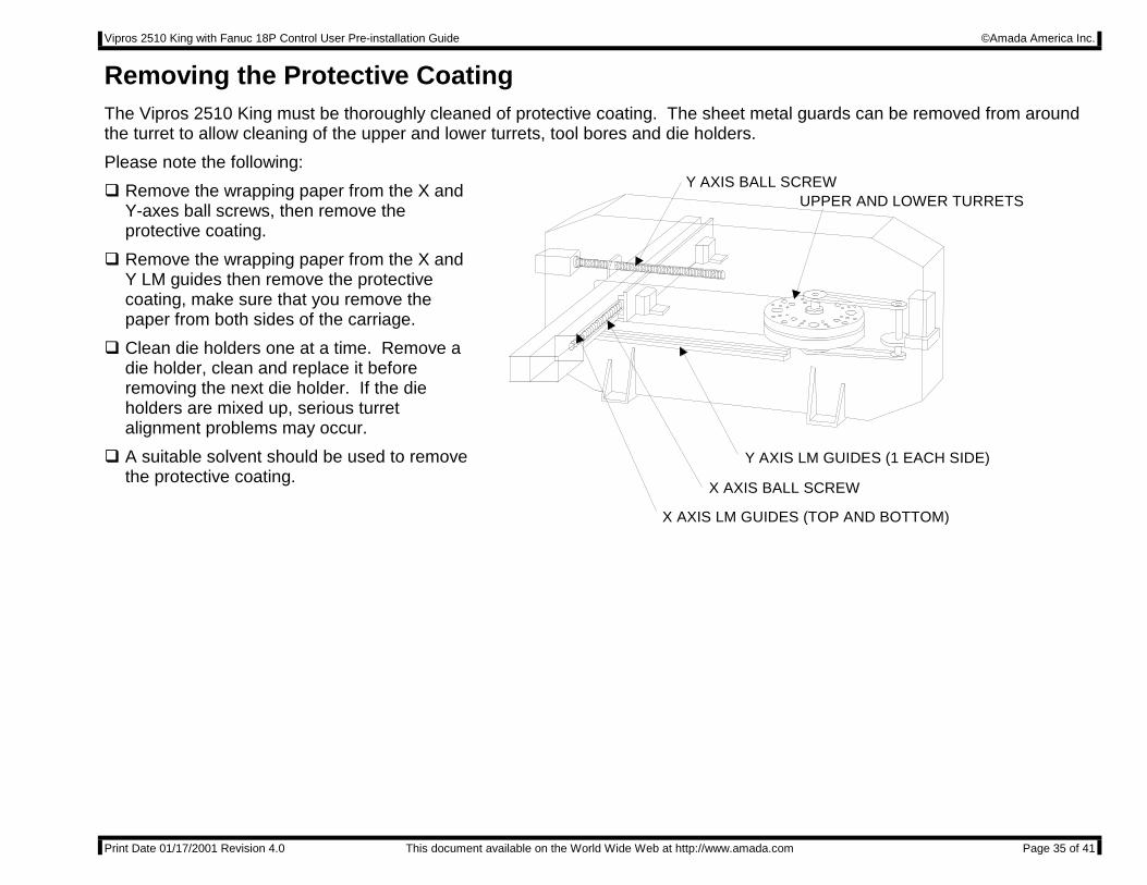
Removing the Protective CoatingThe Vipros 2510 King must be thoroughly cleaned of protective coating. The sheet metal guards can be removed from aroundthe turret to allow cleaning of the upper and lower turrets, tool bores and die holders.
Please note the following:
" Remove the wrapping paper from the X andY-axes ball screws, then remove theprotective coating.
" Remove the wrapping paper from the X andY LM guides then remove the protectivecoating, make sure that you remove thepaper from both sides of the carriage.
" Clean die holders one at a time. Remove adie holder, clean and replace it beforeremoving the next die holder. If the dieholders are mixed up, serious turretalignment problems may occur.
" A suitable solvent should be used to removethe protective coating.
Y AXIS BALL SCREW
X AXIS BALL SCREW
Y AXIS LM GUIDES (1 EACH SIDE)
X AXIS LM GUIDES (TOP AND BOTTOM)
UPPER AND LOWER TURRETS
Vipros 2510 King with Fanuc 18P Control User Pre-installation Guide ©Amada America Inc.
Print Date 01/17/2001 Revision 4.0 This document available on the World Wide Web at http://www.amada.com Page 36 of 41
Machine LevelingProper Machine leveling is critical to the Vipros 2510 King performing as designed.
Materials and tools required:
Supplied with the machine:
Assorted thickness machine leveling shim stock
Anchor bolts
Supplied by AESI service:
Spirit level capable of reading 0.0005"/ft
One-(1) 12 ton hydraulic bottle jack
Not supplied:
Additional shim stock of 0.005" thickness may be required to achieve a properly leveled machine.
Rocking TestAfter the machine frame has been leveled the use of the following G-code is necessary to determine that the machine frameis properly leveled and balanced.
Should the machine frame vibrate or move excessively during the rocking test the machine frame must be re-leveled usingthe procedure in this manual.
Should the proper leveling technique not eliminate the excessive frame motion, consideration must be given to relocation ofthe machine or replacement of the existing floor with an adequate foundation.
Repeat the following test program with a X-axis motion values of -.25” -.5”, -1.” -4.”.
G92X98.425Y50.000G06A.050B0M500N1G91X-.25TTTT (Use any valid tool number)X.25M97P1G50
Vipros 2510 King with Fanuc 18P Control User Pre-installation Guide ©Amada America Inc.
Print Date 01/17/2001 Revision 4.0 This document available on the World Wide Web at http://www.amada.com Page 37 of 41
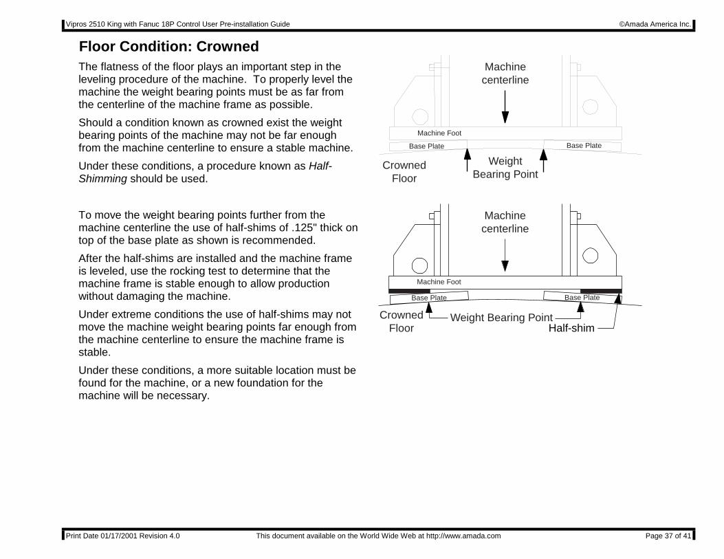
Floor Condition: CrownedThe flatness of the floor plays an important step in theleveling procedure of the machine. To properly level themachine the weight bearing points must be as far fromthe centerline of the machine frame as possible.
Should a condition known as crowned exist the weightbearing points of the machine may not be far enoughfrom the machine centerline to ensure a stable machine.
Under these conditions, a procedure known as Half-Shimming should be used.
CrownedFloor
WeightBearing Point
Machinecenterline
Base Plate Base Plate
Machine Foot
To move the weight bearing points further from themachine centerline the use of half-shims of .125" thick ontop of the base plate as shown is recommended.
After the half-shims are installed and the machine frameis leveled, use the rocking test to determine that themachine frame is stable enough to allow productionwithout damaging the machine.
Under extreme conditions the use of half-shims may notmove the machine weight bearing points far enough fromthe machine centerline to ensure the machine frame isstable.
Under these conditions, a more suitable location must befound for the machine, or a new foundation for themachine will be necessary.
CrownedFloor
Weight Bearing Point
Machinecenterline
Half-shim
Base Plate Base Plate
Machine Foot
Vipros 2510 King with Fanuc 18P Control User Pre-installation Guide ©Amada America Inc.
Print Date 01/17/2001 Revision 4.0 This document available on the World Wide Web at http://www.amada.com Page 38 of 41
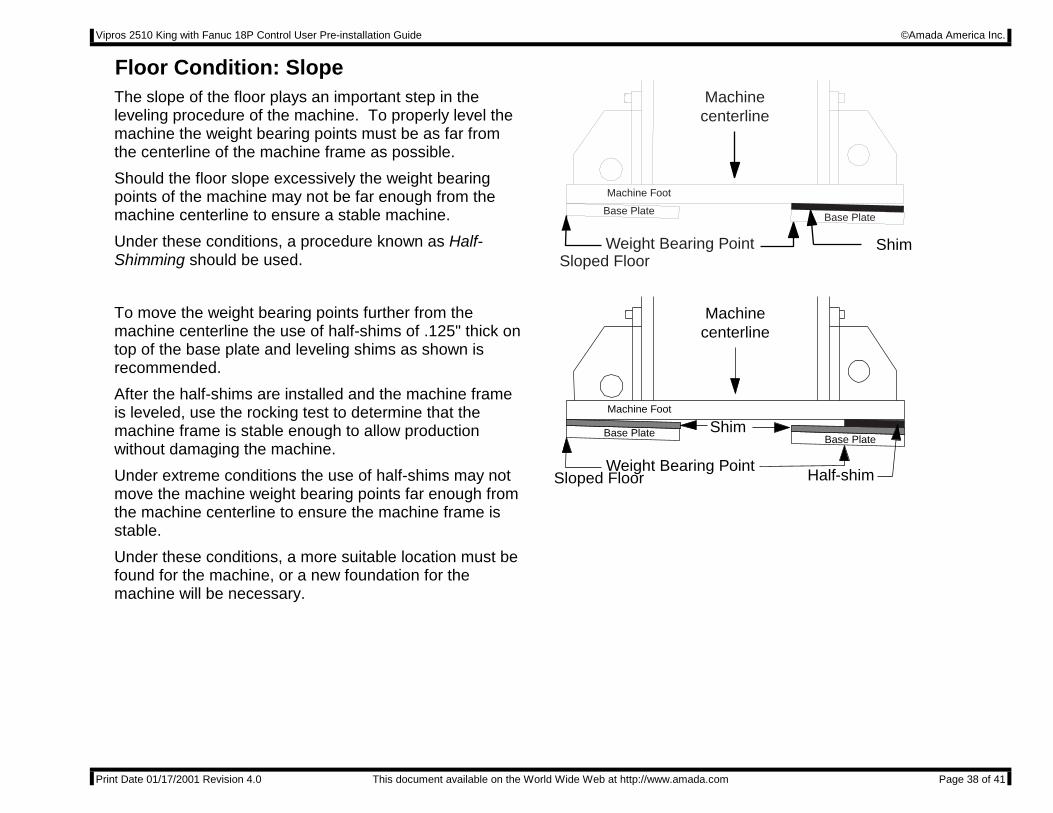
Floor Condition: SlopeThe slope of the floor plays an important step in theleveling procedure of the machine. To properly level themachine the weight bearing points must be as far fromthe centerline of the machine frame as possible.
Should the floor slope excessively the weight bearingpoints of the machine may not be far enough from themachine centerline to ensure a stable machine.
Under these conditions, a procedure known as Half-Shimming should be used. Sloped Floor
Weight Bearing Point
Machinecenterline
Shim
Base PlateBase Plate
Machine Foot
To move the weight bearing points further from themachine centerline the use of half-shims of .125" thick ontop of the base plate and leveling shims as shown isrecommended.
After the half-shims are installed and the machine frameis leveled, use the rocking test to determine that themachine frame is stable enough to allow productionwithout damaging the machine.
Under extreme conditions the use of half-shims may notmove the machine weight bearing points far enough fromthe machine centerline to ensure the machine frame isstable.
Under these conditions, a more suitable location must befound for the machine, or a new foundation for themachine will be necessary.
Sloped FloorWeight Bearing Point
Machinecenterline
Base PlateBase Plate
Machine Foot
Half-shim
Shim
Vipros 2510 King with Fanuc 18P Control User Pre-installation Guide ©Amada America Inc.
Print Date 01/17/2001 Revision 4.0 This document available on the World Wide Web at http://www.amada.com Page 39 of 41
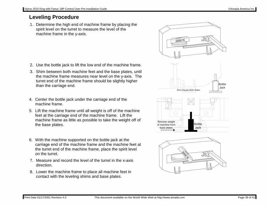
Leveling Procedure1. Determine the high end of machine frame by placing the
spirit level on the turret to measure the level of themachine frame in the y-axis.
2. Use the bottle jack to lift the low end of the machine frame.
3. Shim between both machine feet and the base plates, untilthe machine frame measures near level on the y-axis. Theturret end of the machine frame should be slightly higherthan the carriage end.
4. Center the bottle jack under the carriage end of themachine frame.
5. Lift the machine frame until all weight is off of the machinefeet at the carriage end of the machine frame. Lift themachine frame as little as possible to take the weight off ofthe base plates.
Remove weightof machine from
base platesBottleJack
6. With the machine supported on the bottle jack at thecarriage end of the machine frame and the machine feet atthe turret end of the machine frame, place the spirit levelon the turret.
7. Measure and record the level of the turret in the x-axisdirection.
8. Lower the machine frame to place all machine feet incontact with the leveling shims and base plates.
Vipros 2510 King with Fanuc 18P Control User Pre-installation Guide ©Amada America Inc.
Print Date 01/17/2001 Revision 4.0 This document available on the World Wide Web at http://www.amada.com Page 40 of 41
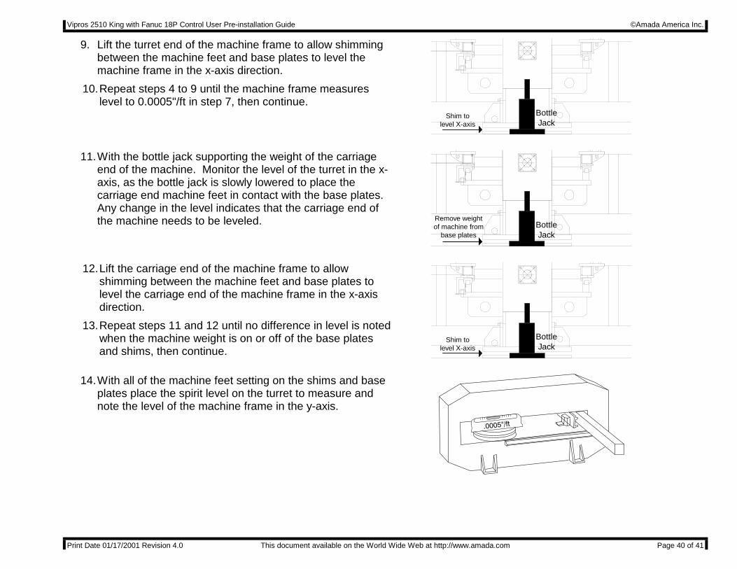
9. Lift the turret end of the machine frame to allow shimmingbetween the machine feet and base plates to level themachine frame in the x-axis direction.
10. Repeat steps 4 to 9 until the machine frame measureslevel to 0.0005"/ft in step 7, then continue.
Shim tolevel X-axis
BottleJack
11. With the bottle jack supporting the weight of the carriageend of the machine. Monitor the level of the turret in the x-axis, as the bottle jack is slowly lowered to place thecarriage end machine feet in contact with the base plates.Any change in the level indicates that the carriage end ofthe machine needs to be leveled. Remove weight
of machine frombase plates
BottleJack
12. Lift the carriage end of the machine frame to allowshimming between the machine feet and base plates tolevel the carriage end of the machine frame in the x-axisdirection.
13. Repeat steps 11 and 12 until no difference in level is notedwhen the machine weight is on or off of the base platesand shims, then continue.
Shim tolevel X-axis
BottleJack
14. With all of the machine feet setting on the shims and baseplates place the spirit level on the turret to measure andnote the level of the machine frame in the y-axis.
Vipros 2510 King with Fanuc 18P Control User Pre-installation Guide ©Amada America Inc.
Print Date 01/17/2001 Revision 4.0 This document available on the World Wide Web at http://www.amada.com Page 41 of 41
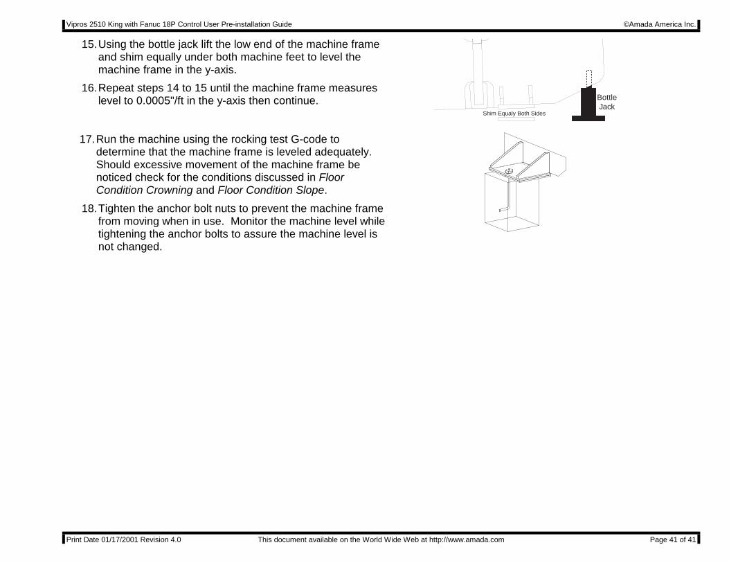
15. Using the bottle jack lift the low end of the machine frameand shim equally under both machine feet to level themachine frame in the y-axis.
16. Repeat steps 14 to 15 until the machine frame measureslevel to 0.0005"/ft in the y-axis then continue.
Shim Equaly Both Sides
BottleJack
17. Run the machine using the rocking test G-code todetermine that the machine frame is leveled adequately.Should excessive movement of the machine frame benoticed check for the conditions discussed in FloorCondition Crowning and Floor Condition Slope.
18. Tighten the anchor bolt nuts to prevent the machine framefrom moving when in use. Monitor the machine level whiletightening the anchor bolts to assure the machine level isnot changed.