videoportero inalambrico panasonic - cctv center · the panasonic wireless video intercom system...
TRANSCRIPT

Wireless Video Intercom SystemVL-SWD501EX/UEX
A n y w h e r e E a s i l y

The Panasonic Wireless Video Intercom System watches over the safety of your entire house
View and TalkEasy
Easy
Easy
Whole house connection with wireless devices
Safety
Expansion
Kitchen Second Floor Bedroom Balcony Garage And more…
Wireless allows flexible layouts and easy operation.
The sub monitors can be easily and flexibly installed, with no wiring work required.
You can check anywhere you want, from any location in your house, with easy wireless operation.
Wireless Monitor Station
2
Door Station
Electric lock release support for gate
Wireless Sensor Camera
(Doorphone)
Main Monitor Station
(Main monitor)
(Sub monitor)
Optional Accessory
3

Easy view and talk
Electric Lock Release Support for GateThe electric lock release supports up to 4 systems, each of which can be operated from the main monitor or a sub monitor. The gate or door lock can be easily and quickly released even from the second floor of the house.
4
Anywhere Convenience (Wireless Operation)It's wireless, so you can move around the house freely without having to worry about cords. You can greet visitors from places in the house that are within the range of the main monitor signal. And you can also add on up to six sub monitors.
Slim DesignOnly 21 mm deep, the main monitor has a slim design that blends in with virtually all room interiors. The stylish doorphone allows both mounted and mount-free use. Choose the type of use that matches your installation conditions and your home's design.
Large Touch PanelThe main monitor has a large, 5-inch wide screen that clearly shows each visitor's face. If it is difficult to see, simply touch the screen to activate an approximate 2x zoom horizontally and vertically. This makes it easy for everyone to see, and provides an easy-to-use operating screen.
21mm
5
* When connecting three or more, an optional doorphone is required.

Easy Safety
6 7
Wide-Angle CameraThe doorphone features an wide-angle lens that covers approximately 170 degrees horizontally and 115 degrees vertically. It gives you images with minimal distortion regardless of the number of people being viewed, or the height of each person. The wide range also increases freedom for choosing the installation location.
SD Card RecordingYou can automatically record video images of visitors while you're away from home. It will record up to 3,000 visitors (30 seconds per visitor). This shows you details that aren't possible with still images. And you can save and play the images on a PC that has an SD card slot.* The SD Memory Card is sold separately. Please use an SD Memory Card with a capacity of 2 GB or more.** The number of recordings is an estimate for use as a guide only. When the card becomes full, images will be automatically deleted, starting with the oldest, to record new images.
Wireless Sensor Cameras By installing the optional DECT Wireless Sensor Camera, you can use human (heat) and motion sensors to monitor locations that you are concerned about. At night, a white LED shines to drive intruders away. There is no need to wire it to the doorphone. Installation is possible wherever there is a power supply.
Recorded image type
• When using a camera, we recommend using an SD card with a capacity of 4 GB or more.• The number of images that can be recorded in the table are just a guide and may differ from the actual number of images that can be recorded.• Because SD cards contain data such as file system management information, the complete capacity cannot be used to save data. When other data is saved to an SD card, the number of images and videos that can be saved is reduced.• The upper limit for saving images is 3,000 images regardless of SD card capacity.
Capacity 2GB 4GB 8GB 16GB 32GB 48GB 64GB
Doorphone images only 125 255 520 1,040 2,090 3,000 3,000
Camera images only 2,300 3,000 3,000 3,000 3,000 3,000 3,000
4Up to
6Up to
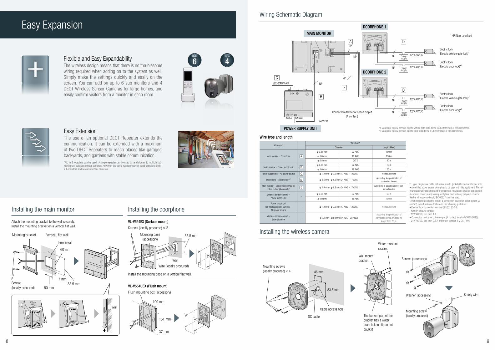
Easy Expansion
8 9
Installing the wireless camera
Installing the main monitor Installing the doorphone
Wiring Schematic Diagram
Mounting screws (locally procured) × 4 46 mm
83.5 mm
Cable access hole
DC cable
Water resistant sealant
Wall mount bracket
The bottom part of the bracket has a water drain hole on it; do not caulk it
Mounting base(accessory)
Wire (locally procured)
Wall
83.5 mm
Screws (locally procured) × 2
Install the mounting base on a vertical flat wall.
Attach the mounting bracket to the wall securely. Install the mounting bracket on a vertical flat wall.
VL-V554EX (Surface mount)
Flush mounting box (accessory)
VL-V554UEX (Flush mount)
100 mm
151 mm
37 mm
Vertical, flat wall
Screws (locally procured)
Hole in wall
83.5 mm
60 mm
7 mm
50 mm
Mounting bracket
Wall
POWER SUPPLY UNIT
MAIN MONITOR
DOORPHONE 1
DOORPHONE 2
220-240 V AC
Connection device for option output (A contact)
*1 Make sure to only connect electric vehicle gate locks to the S3/S4 terminals of the doorphones.*2 Make sure to only connect electric door locks to the S1/S2 terminals of the doorphones.
NP: Non-polarised
Power supply
Power supply
Power supply
Power supply
12 V AC/DC
12 V AC/DC
12 V AC/DC
12 V AC/DC
Electric lock(Electric door lock)*2
Electric lock(Electric door lock)*2
Electric lock (Electric vehicle gate lock)*1
Electric lock (Electric vehicle gate lock)*1
24 V DC
A
B
ED
D
CNP
NP
NP
NP
NP
NP
NP
NP
Wire type and length
Wiring runWire type*1
Diameter Length (Max.)
Main monitor – Doorphone
φ 0.65 mm 22 AWG 100 m
φ 1.0 mm 18 AWG 130 m
φ 0.5 mm CAT 5 50 m
Main monitor – Power supply unit φ 0.65 mm 22 AWG 10 m
φ 1.0 mm 18 AWG 20 m
Power supply unit – AC power source φ 1.2 mm - φ 2.0 mm (17 AWG - 12 AWG) No requirement
Doorphone – Electric lock*2 φ 0.5 mm - φ 1.2 mm (24 AWG - 17 AWG)According to specification of
connected device.
Main monitor – Connection device for option output (A contact)*2 φ 0.5 mm - φ 1.2 mm (24 AWG - 17 AWG)
According to specification of con-nected device.
Wireless sensor camera –Power supply unit
–φ 0.65 mm 22 AWG 50 m
φ 1.0 mm 18 AWG 100 m
Power supply unit (for wireless sensor camera) –
AC power source– φ 1.2 mm - φ 2.0 mm (17 AWG - 12 AWG) No requirement
Wireless sensor camera –External sensor
– φ 0.5 mm - φ 0.8mm (24 AWG - 20 AWG)According to specification of
connected device. Must be no longer than 20 m.
*1 Type: Single-pair cable with outer sheath (jacket) Conductor: Copper solid• A certified power supply wiring has to be used with this equipment. The rel-evant national installation and/or equipment regulations shall be considered. A certified power supply wiring not lighter than ordinary polyvinyl chloride flexible wiring according to IEC 60227 shall be used.*2 When using an electric lock or a connection device for option output (A contact), select a device that meets the following guidelines:• Electric lock connection terminal (S1/S2, S3/S4): - N/O dry closure contact- 12 V AC/DC, less than 1 A• Connection device for option output (A contact) terminal (OUT1/OUT2): - 24 V AC/DC, less than 0.3 A (minimum contact: 5 V DC 1 mA)
Flexible and Easy ExpandabilityThe wireless design means that there is no troublesome wiring required when adding on to the system as well. Simply make the settings quickly and easily on the screen. You can add on up to 6 sub monitors and 4 DECT Wireless Sensor Cameras for large homes, and easily confirm visitors from a monitor in each room.
Easy ExtensionThe use of an optional DECT Repeater extends the communication. It can be extended with a maximum of two DECT Repeaters to reach places like garages, backyards, and gardens with stable communication.* Up to 2 repeaters can be used. A single repeater can be used to send signals to multiple sub monitors or wireless sensor cameras. However, the same repeater cannot send signals to both sub monitors and wireless sensor cameras.
C
B
A
D
E
Screws (accessory)
Washer (accessory) Safety wire
Mounting screw (locally procured)

Specifications
165 mmMain body Charger
100 mm
118 mm52 mm 30 mm30 mm
16.5 mm
35.8 mm
81 mm 76 mm
43 mm
21 mm
180 mm
116 mm
169 mm173 mm
*Indoor use only.
118 mm
142 mm 94 mm
111 mm 39 mm290 mm
160 mm
82 mm
10 11
Model name and numberWireless Sensor Camera
VL-WD812EXDECT Repeater
VL-FKD2EXPower Supply Unit (part)
VL-PS240
Dimensions
Power sourcePower supply unit (VL-PS240)
24 V DC, 0.4 A
AC adaptor (PQLV219CE/PQLV219E) Input: 220-240 V AC, 0.1 A, 50/60 Hz
Output: 6.5 V DC, 0.5 A
Input: 200-240 V AC, 0.2 A, 50/60 Hz Output: 24 V DC, 0.6 A
Power consumption
During standby: approx. 1.5 W During operation: approx. 4.5 W (when the LED lights are
not lit), approx. 8 W (when the LED lights are lit)
During standby: approx. 1.5 W During operation: approx. 2.3 W
(when transmitting)-
Dimensions (mm) (height x width x depth)
Approx. 160 x 118 x 290 mm (when the camera is front facing and including the wall
mount bracket)Approx. 82 x 111 x 39 mm
Approx. 116 x 100 x 54 mm (excluding protruding sections)
Weight Approx. 960 g Approx. 88 g (excluding the AC adaptor) Approx. 230 g
Operating Environment Ambient temperature: approx.-20°C to +50°CRelative humidity (non-condensing): up to 90%
Ambient temperature: approx. 0 °C to +40 °C Relative humidity (non-condensing): up to 90 %
Ambient temperature: approx.0°C to +40°C Relative humidity (non-condensing): up to 90%
Frequency range 1.88 GHz to 1.90 GHz 1.88 GHz to 1.90 GHz -Installation method Wall mount (wall mount bracket supplied) - Attach to DIN rail
Transmitting rangeApprox. 100 m
(line-of-sight distance from the main monitor)Approx. 100 m
(line-of-sight distance from the main monitor)-
Minimum illuminance required 1 lx*1 - -Image sensor 0.3 M pixel CMOS - -Lighting method 2 white LED lights*2 - -Angular field of view (camera angle)
Horizontal: approx. 53°,vertical: approx. 41°
- -
Sensor detection methodPyroelectric infrared sensor
(heat sensor) and motion detection- -
Sensor detection range
• Heat sensor (when the surrounding temperature is approx. 20°)
Horizontal: approx. 63°, vertical: approx. 20°, detection range: approx. 5 m • Motion detection sensor
Horizontal: approx. 53°, vertical: approx. 41°
- -
IP rating IP54*3 - -
Adjustable mounting anglesHorizontal: ±90°, vertical: facing forward
- facing down approx. 60° (adjustable when mounting)
- -
Heat sensor adjustable angles Manually adjustable to 2 angles - -
Included Accessories
Power supply unit (VL-PS240) x 1, Cable binder x 2,
Wall mount bracket x 1, Screw x 4, Sensor range cap x 1 set of 4, Cap removement tool x 1,
Screw cover x 4, Washer x 1
AC adaptor x 2 (PQLV219CE x 1, PQLV219E x 1) *4 -
Model name and numberMain Unit (Main monitor)
VL-MWD501EX
Door Station (Doorphone)VL-V554EX (Surface mount) /VL-V554UEX (Flush mount)
Wireless Monitor Station (Sub monitor)VL-WD613EX
Dimensions
Power sourcePower supply unit (VL-PS240)
24 V DC, 0.5 A
Power supplied by the main monitor
20 V DC, 0.23 ARechargeable Ni-MH (AAA x 2)
AC adaptor (PNLV226CE/PNLV226E) Input: 220-240 V AC, 0.1 A,
50/60 Hz Output: 5.5 V DC, 0.5 A
Power consumptionStandby: approx. 1.4 W
During operation: approx. 10 W- -
Standby: approx. 0.4 W (when the sub monitor is not placed in the
charger) During charging: approx. 1.4 W
Dimensions (mm) (height x width x depth)
Approx. 180 x 165 x 21 mm (excluding protruding sections)
VL-V554EX: Approx. 169 x 118 x 30 mm
(excluding protruding sections) VL-V554UEX:
Approx. 169 x 118 x 16.5 mm (excluding sections embedded into the wall)
Approx. 173 x 52 x 30 mm (excluding protruding sections)
Approx. 43 x 81 x 76 mm (excluding protruding sections)
Weight Approx. 470 gVL-V554EX: approx. 405 g
VL-V554UEX: approx. 345 gApprox. 160 g
(including the batteries)Approx. 70 g
(excluding the AC adaptor)
Operating environment
Ambient temperature: approx.0°C to +40°C
Relative humidity (non-condensing): up to 90%
Ambient temperature: Approx. -10°C to +50°C
Relative humidity (non-condensing): up to 90%
Ambient temperature: Approx. 0°C to +40°C
Relative humidity (non-condensing): up to 90%
Ambient temperature: Approx. 0°C to +40°C
Relative humidity (non-condensing): up to 90%
Display Approx. 5 inches, wide colour display -Approx. 2.2 inches,
colour display-
Frequency 1.88 GHz to 1.90 GHz - 1.88 GHz to 1.90 GHz -Talking method Hands-free - Hands-free -
Viewing angle -Horizontally: approx. 170°Vertically: approx. 115°
- -
Installation methodWall mount
(mounting bracket supplied)
VL-V554EX: surface mount (mounting base supplied) VL-V554UEX: flush mount
(flush mounting box supplied)
- -
Option output (A contact)
Rated load: 24 V AC/DC, 0.3 A or lower Minimum applicable load:
5 V DC, 0.001 A (Output when there is a call from the
doorphone)
- - -
Minimum illuminance required -1 lx (within approx.
50 cm from the camera lens)- -
Lighting method - LED lights - -Dust protection / water protection - IP54 *1 - -Registance against impacts - Compliant with IK07 - -Operating time *2 - - Standby use: approx. 80 hours -Charging time *3 - - Approx. 8 hours *4 -
Transmitting range - -Approx. 100 m
(line-of-sight distance from the main monitor)
-
Included Accessories Power supply unit (VL-PS240) x 1, Mounting
bracket x 1, Cable binder x 3
Mounting base x 1 (EX only), Flush mounting box x 1 (UEX only), Screw x 4, Name plate x 2,
Hex wrench x 1
AC adaptor x 2 (PNLV226CE x 1, PNLV226E x 1) *5, Rechargeable battery x 2, Charger x 1
VL-SWD501EX VL-MWD501EX x 1, VL-WD613EX x 1, VL-V554EX x 1VL-SWD501UEX VL-MWD501EX x 1, VL-WD613EX x 1, VL-V554UEX x 1
*1 Water resistance is only assured if the doorphone is installed correctly according to the instructions in the Installation Guide, and appropriate water protection measures are taken. *2 When used fully charged in an operating temperature of 20°C.*3 When the operating temperature is 20°C. The charging time may increase when the operating temperature is lower than this. *4 When registered to the main monitor. *5 Please use the plug type that matches the power supply in your region from the two plug types provided.
Door Station (Doorphone)
VL-V554EX (Surface mount)VL-V554UEX (Flush mount)
Main Monitor Station (Main monitor)
VL-MWD501EX
Wireless Monitor Station(Sub monitor)
VL-WD613EX
Wireless Sensor Camera
VL-WD812EX
DECT Repeater
VL-FKD2EX
2Up to
4Up to
2Up to
6Up to
Model Composition
Specifications
Specifications (Parts)
*1 The minimum illuminance required when the camera’s [Brightness] setting is set to [+3].*2 Approx. 8.5 lx when 3 m in front of the camera, and approx. 4 lx when 3 m away and 20° to the left or right of the camera. *3 Water resistance is only assured if the camera is installed correctly according to the instructions in the Installation Guide, and appropriate water protection measures are taken. Do not install the camera in areas directly exposed to water or rain. *4 Please use the plug type that matches the power supply in your region from the two plug types provided.

Door StationVL-V554EX/VL-V554UEX
Door StationVL-V554EX/VL-V554UEX
Garage
Basic System Component (VL-SWD501EX/VL-SWD501UEX)
Optional Expandability
• A power supply (100 VAC) is required for installation.• Up to 2 repeaters can be used. A single repeater can be used to send signals to multiple sub monitors or wireless sensor cameras. However, the same repeater cannot send signals to both sub monitors and wireless sensor cameras.
2Up to
2Up to
6Up to
4Up to
Main Monitor Station VL-MWD501EX
5-inch wide screen touch panel
2.2-inch TFT
colour LCD
Wireless Monitor Station VL-WD613EX
Wireless Monitor Station VL-WD613EX
Wireless Sensor Camera VL-WD812EX
DECT Repeater VL-FKD2EX
Trademarks and registered trademarks - The microSDHC Logo is a trademark of SD-3C, LLC.- The software of the sub monitor is based in part on the work of the Independent JPG Group. All other trademarks identified herein are the property of their respective owners.Important- Safety Precaution: carefully read the operating instructions and installation manual before using this product.
• The actual product may vary slightly from photograph.• All pictures of the LCD display are simulated.• Weights and dimensions are approximate. • Design and Specifications are subject to change without notice. • These products may be subject to export control regulations.
DISTRIBUTED BY :
MG-DHPC004EN 1312NSP/ZZZ - EX1
System Configuration Example
Bed room Room 1
Living Room Kitchen Den
Room 2