vickers cartridge valves circuit...
TRANSCRIPT
Revised 5/96 737
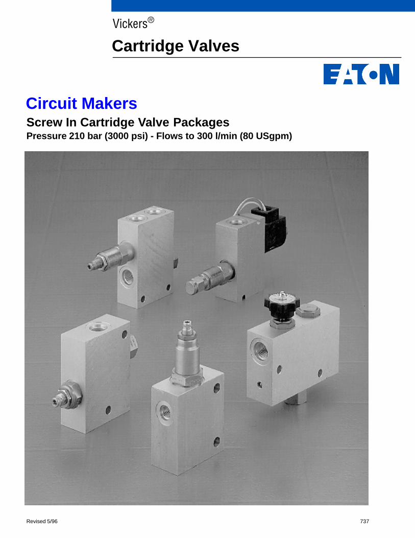
Screw In Cartridge Valve PackagesPressure 210 bar (3000 psi) - Flows to 300 l/min (80 USgpm)
Vickers®
Cartridge Valves
Circuit Makers
2
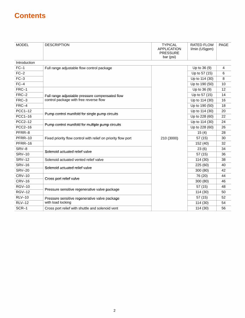
Contents
MODEL DESCRIPTION TYPICALAPPLICATIONPRESSURE
bar (psi)
RATED FLOWl/min (USgpm)
PAGE
IntroductionFC–1 Full range adjustable flow control package Up to 36 (9) 4
FC–2g j g
Up to 57 (15) 6
FC–3 Up to 114 (30) 8
FC–4 Up to 190 (50) 10
FRC–1 Up to 36 (9) 12
FRC–2 Full range adjustable pressure compensated flow Up to 57 (15) 14
FRC–3Full range adjustable ressure com ensated flowcontrol package with free reverse flow Up to 114 (30) 16
FRC–4
g
Up to 190 (50) 18
PCC1–12P mp control m nifold for single p mp circ its
Up to 114 (30) 20
PCC1–16Pump control manifold for single pump circuits
Up to 228 (60) 22
PCC2–12P mp control m nifold for m ltiple p mp circ its
Up to 114 (30) 24
PCC2–16Pump control manifold for multiple pump circuits
Up to 228 (60) 26
PFRR–8 15 (4) 28
PFRR–10 Fixed priority flow control with relief on priority flow port 210 (3000) 57 (15) 30
PFRR–16y y ( )
152 (40) 32
SRV–8Solenoid ct ted relief v lve
23 (6) 34
SRV–10Solenoid actuated relief valve
57 (15) 36
SRV–12 Solenoid actuated vented relief valve 114 (30) 38
SRV–16Solenoid ct ted relief v lve
225 (60) 40
SRV–20Solenoid actuated relief valve
300 (80) 42
CRV–10Cross port relief v lve
76 (20) 44
CRV–16Cross port relief valve
300 (80) 46
RGV–10Press re sensitive regener tive v lve p ck ge
57 (15) 48
RGV–12Pressure sensitive regenerative valve package
114 (30) 50
RLV–10 Pressure sensitive regenerative valve package 57 (15) 52
RLV–12Pressure sensitive regenerative valve ackagewith load locking 114 (30) 54
SCR–1 Cross port relief with shuttle and solenoid vent 114 (30) 56
3
Introduction
For over 70 years, Vickers has provided itscustomers with quality products andinnovative solutions for all their power andmotion control needs.
In keeping with this tradition and byleveraging both the very best in screw-incartridge valve engineering design andusing technology and knowledge gainedfrom over 20 years of MCD design andpackaging techniques, Vickers is pleasedto offer this line of Circuit Maker products.
Circuit Maker Products are pre-engineeredpackages. These packages are designedwith from 2 to 4 screw–in cartridge valvesfor generic, repetitive circuit controlfunctions.
All of the products in this catalog are ratedat 210 bar (3000 psi) and have either SAEor BSPP port options. Our selection ofCircuit Maker pre-engineered packagesconsists of the following basic units:
� Single and multiple pump controlpackages
� Solenoid actuated relief valvepackages
� Flow control packages
� Cross port relief packages
� Cross port relief with shuttle andsolenoid vent
� Pressure sensitive regenerationpackages with and without loadlocking.
Typical ApplicationsCircuit Maker packages can be used in awide variety of Industrial and Mobileapplications. The are designed to solve amultitude of repeatable, generic applicationrequirements that are encountered in dayto day hydraulic circuits. These packagesare ideal solutions for specialty machinerequirements and low volume options onhigh volume applications.
Pump control packages –These are suitable for any single ormultiple pump application where individualpump output flow does not exceed 228l/min (60 USgpm). They are used toprovide air-bleed, start-up and reliefprotection.
Solenoid actuated relief valvepackages –These can be used wherever remote reliefor venting control is required for flows up to300 l/min (80 USgpm). Normally openversions lend themselves to marketswhere fail safe and “dead man” control areimportant. Normally closed versions lendthemselves to markets such as machinetool, where energy savings can beobtained by selective unloading of pumpflow.
Flow control packages –These packages are used with both fixedand variable pump systems to provideconstant output flow for the main or branchcircuits. Packages offered provide formaintaining either:– cylinder or motor speed;
free reverse flow for table positioning, conveyor systems and presses
– controlled flow for steering systems.
Cross port relief valve packages –These packages are used withbi-directional actuators. The circuit makerprovides actuator protection from overloadconditions.
Pressure sensitive regenerationpackages –Pressure sensitive regeneration packagesprovides a means of extending a cylinderas fast as possible without additional pumpflow by diverting rod end flow to the headend to accelerate the load. When thepressure in the head end reaches apredetermined level related to the load, thevalve closes off and the cylinder returns tonormal speed. Typical applications are foroutriggers/stabilizers in mobile marketsand machine tool traverse in industrialmarkets.
Pressure sensitive regenerationpackages with load locking –Pressure sensitive regeneration packagesprovides a means of extending a cylinderas fast as possible without additional pumpflow by diverting rod end flow to the headend to accelerate the load. When thepressure in the head end reaches apredetermined level related to the load, thevalve closes off and the cylinder returns tonormal speed. The load locking featureprovides stability as the system is nowworking with an oil column under pressurein addition to the mechanical structure.
Typically used with mobile crane and othersimilar vehicles to ensure stability whenswinging loads. This package has anadvantage over alternative systems thatuse solenoid actuated blocking pins. In theevent of a power failure, it is still possible tolower the vehicle/load.
Features and Benefits� Quick solutions that are ready to use
� Quick delivery at low cost
� Flexibility
Quick solutions: Circuit Maker packagesare pre-engineered packaged solutions forgeneric, repeatable requirements. Theyhave specific coil voltage, coil connector,flow settings adjustment and pressuresetting adjustment options that permittailoring to application requirements.
Quick delivery/low cost: Circuit Makerpackages have already been engineeredto satisfy generic, repetitive circuit needs.There are no scheduling or time relatedproblems, or engineering charges to berecovered.
Flexibility: Screw-in cartridge valves andhousings are sold either separately or aspre–assembled packages. This permitslast minute assembly of packages andlocal tailoring of individual valve options.
4
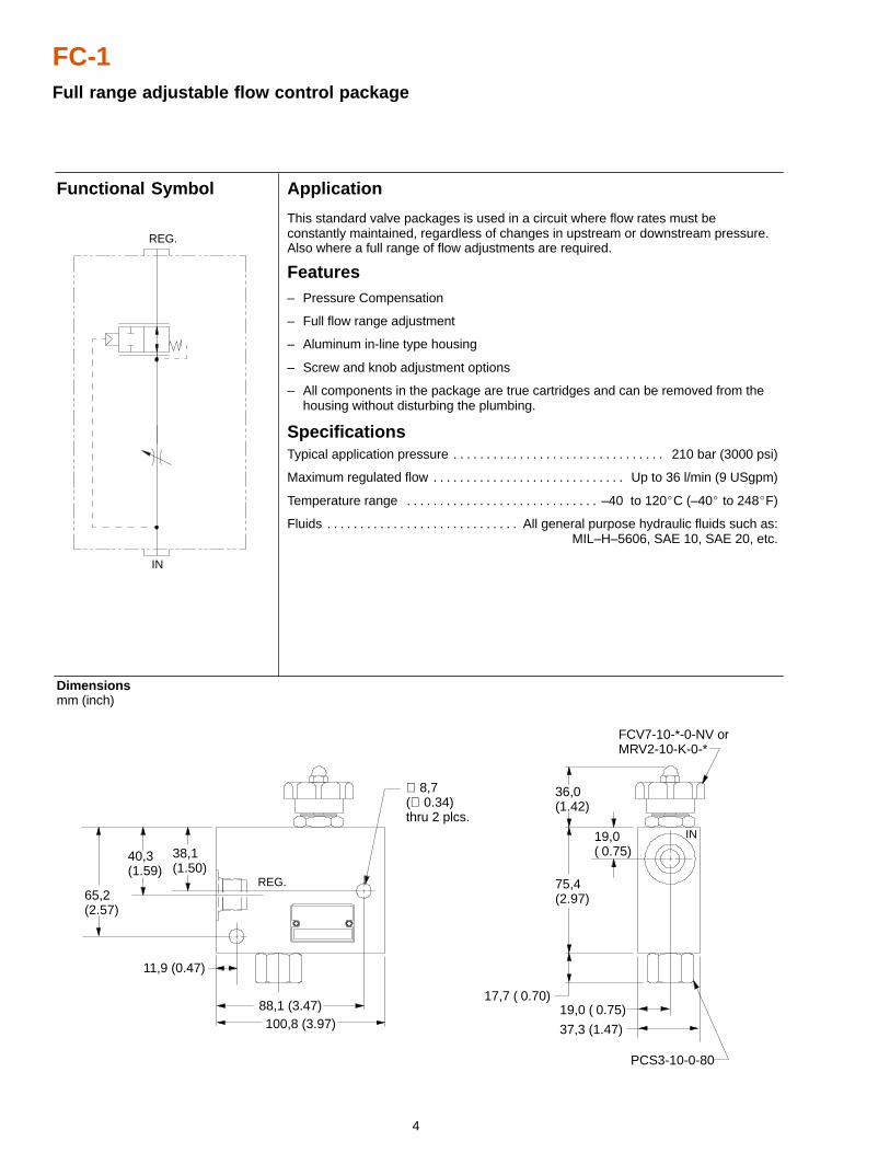
FC-1Full range adjustable flow control package
Application
This standard valve packages is used in a circuit where flow rates must beconstantly maintained, regardless of changes in upstream or downstream pressure.Also where a full range of flow adjustments are required.
Features– Pressure Compensation
– Full flow range adjustment
– Aluminum in-line type housing
– Screw and knob adjustment options
– All components in the package are true cartridges and can be removed from the housing without disturbing the plumbing.
SpecificationsTypical application pressure 210 bar (3000 psi). . . . . . . . . . . . . . . . . . . . . . . . . . . . . . . .
Maximum regulated flow Up to 36 l/min (9 USgpm). . . . . . . . . . . . . . . . . . . . . . . . . . . . .
Temperature range –40 to 120�C (–40� to 248�F). . . . . . . . . . . . . . . . . . . . . . . . . . . . .
Fluids All general purpose hydraulic fluids such as:. . . . . . . . . . . . . . . . . . . . . . . . . . . . . MIL–H–5606, SAE 10, SAE 20, etc.
Dimensions mm (inch)
Functional Symbol
19,0 ( 0.75)
FCV7-10-*-0-NV orMRV2-10-K-0-*
100,8 (3.97)88,1 (3.47)
65,2(2.57)
40,3(1.59)
38,1(1.50)
∅ 8,7(∅ 0.34)thru 2 plcs.
36,0(1.42)
75,4(2.97)
17,7 ( 0.70)
19,0( 0.75)
PCS3-10-0-80
37,3 (1.47)
REG.
IN
IN
REG.
11,9 (0.47)
5
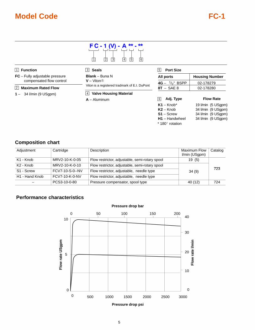
Model Code FC-1
Function
FC – Fully adjustable pressurecompensated flow control
Maximum Rated Flow
1 – 34 l/min (9 USgpm)
5
3 4 5 61 2
1
2
3
4
6
Port Size
All ports Housing Number
4G – 1/2” BSPP8T – SAE 8
02-178279
Adj. Type Flow Rate
K1 – Knob* 19 l/min (5 USgpm)K2 – Knob 34 l/min (9 USgpm)S1 – Screw 34 l/min (9 USgpm)H1 – Handwheel 34 l/min (9 USgpm)
02-178280
* 180� rotation
Seals
Blank – Buna NV – Viton�Viton is a registered tradmark of E.I. DuPont
Valve Housing Material
A – Aluminum
Composition chart
Adjustment Cartridge Description Maximum Flowl/min (USgpm)
Catalog
K1 - Knob MRV2-10-K-0-05 Flow restrictor, adjustable, semi-rotary spool 19 (5)
K2 - Knob MRV2-10-K-0-10 Flow restrictor, adjustable, semi-rotary spool723
S1 - Screw FCV7-10-S-0--NV Flow restrictor, adjustable, needle type 34 (9)723
H1 - Hand Knob FCV7-10-K-0-NV Flow restrictor, adjustable, needle type( )
– PCS3-10-0-80 Pressure compensator, spool type 40 (12) 724
Performance characteristics
0
5
10
0
10
20
30
40
0 500 1000 1500 2000 2500
50 100 1500 200
Pressure drop psi
Pressure drop bar
Flo
w r
ate
US
gp
m
Flo
w r
ate
l/min
3000
6
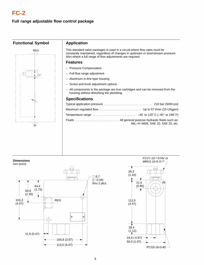
FC-2Full range adjustable flow control package
Application
This standard valve packages is used in a circuit where flow rates must beconstantly maintained, regardless of changes in upstream or downstream pressure.Also where a full range of flow adjustments are required.
Features– Pressure Compensation
– Full flow range adjustment
– Aluminum in-line type housing
– Screw and knob adjustment options
– All components in the package are true cartridges and can be removed from the housing without disturbing the plumbing.
SpecificationsTypical application pressure 210 bar (3000 psi). . . . . . . . . . . . . . . . . . . . . . . . . . . . . . . .
Maximum regulated flow Up to 57 l/min (15 USgpm). . . . . . . . . . . . . . . . . . . . . . . . . . . .
Temperature range –40 to 120�C (–40� to 248�F). . . . . . . . . . . . . . . . . . . . . . . . . . . . .
Fluids All general purpose hydraulic fluids such as:. . . . . . . . . . . . . . . . . . . . . . . . . . . . . MIL–H–5606, SAE 10, SAE 20, etc.
Dimensions mm (inch)
Functional Symbol
36,3(1.43)
113,5(4.47)
28,4(1.12)
21,5(0.85)
24,6 ( 0.97)50,0 (1.97)
PCS3-16-0-80
FCV7-10-*-0-NV orMRV2-10-K-0-**
59,6(2.35)
44,4(1.75)
∅ 8,7(∅ 0.34)thru 2 plcs.
100,8 (3.97)
113,5 (4.47)
11,9 (0.47)
IN
REG103,3(4.07)
IN
REG.
7
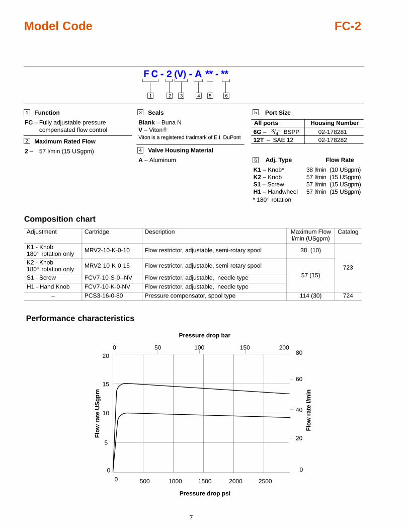
Model Code FC-2
Function
FC – Fully adjustable pressure compensated flow control
Maximum Rated Flow
2 – 57 l/min (15 USgpm)
5
3 4 5 61 2
1
2
3
4
6
Port Size
All ports Housing Number
6G – 3/4” BSPP12T – SAE 12
02-178281
Adj. Type Flow Rate
K1 – Knob* 38 l/min (10 USgpm)K2 – Knob 57 l/min (15 USgpm)S1 – Screw 57 l/min (15 USgpm)H1 – Handwheel 57 l/min (15 USgpm)
02-178282
* 180� rotation
Seals
Blank – Buna NV – Viton�Viton is a registered tradmark of E.I. DuPont
Valve Housing Material
A – Aluminum
Composition chart
Adjustment Cartridge Description Maximum Flowl/min (USgpm)
Catalog
K1 - Knob180� rotation only
MRV2-10-K-0-10 Flow restrictor, adjustable, semi-rotary spool 38 (10)
K2 - Knob180� rotation only
MRV2-10-K-0-15 Flow restrictor, adjustable, semi-rotary spool
57 (15)723
S1 - Screw FCV7-10-S-0--NV Flow restrictor, adjustable, needle type 57 (15)
H1 - Hand Knob FCV7-10-K-0-NV Flow restrictor, adjustable, needle type
– PCS3-16-0-80 Pressure compensator, spool type 114 (30) 724
Performance characteristics
0
5
10
0
20
40
60
80
0 500 1000 1500 2000 2500
50 100 1500 200
Pressure drop psi
Pressure drop bar
Flo
w r
ate
US
gp
m
Flo
w r
ate
l/min
15
20
8
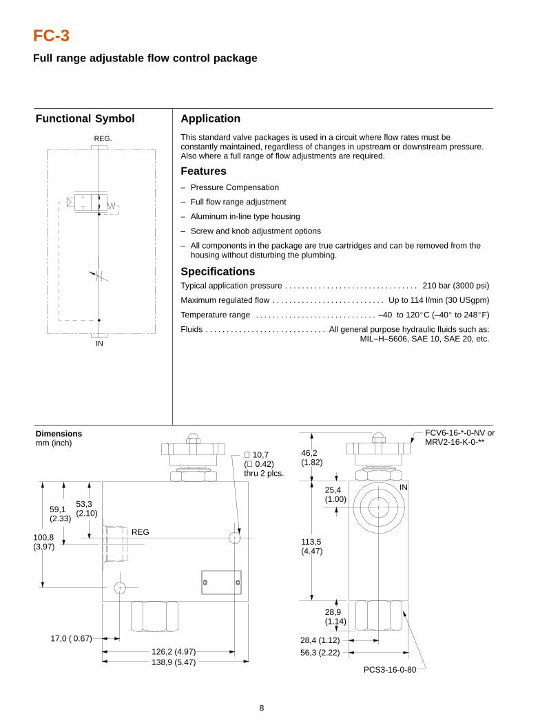
FC-3Full range adjustable flow control package
Application
This standard valve packages is used in a circuit where flow rates must beconstantly maintained, regardless of changes in upstream or downstream pressure.Also where a full range of flow adjustments are required.
Features– Pressure Compensation
– Full flow range adjustment
– Aluminum in-line type housing
– Screw and knob adjustment options
– All components in the package are true cartridges and can be removed from the housing without disturbing the plumbing.
SpecificationsTypical application pressure 210 bar (3000 psi). . . . . . . . . . . . . . . . . . . . . . . . . . . . . . . .
Maximum regulated flow Up to 114 l/min (30 USgpm). . . . . . . . . . . . . . . . . . . . . . . . . . .
Temperature range –40 to 120�C (–40� to 248�F). . . . . . . . . . . . . . . . . . . . . . . . . . . . .
Fluids All general purpose hydraulic fluids such as:. . . . . . . . . . . . . . . . . . . . . . . . . . . . . MIL–H–5606, SAE 10, SAE 20, etc.
Dimensions mm (inch)
Functional Symbol
56,3 (2.22)
28,4 (1.12)
∅ 10,7(∅ 0.42)thru 2 plcs.
113,5(4.47)
46,2(1.82)
59,1(2.33)
17,0 ( 0.67)
126,2 (4.97)138,9 (5.47)
28,9(1.14)
100,8(3.97)
53,3(2.10)
25,4(1.00)
REG
IN
PCS3-16-0-80
FCV6-16-*-0-NV orMRV2-16-K-0-**
IN
REG.
9
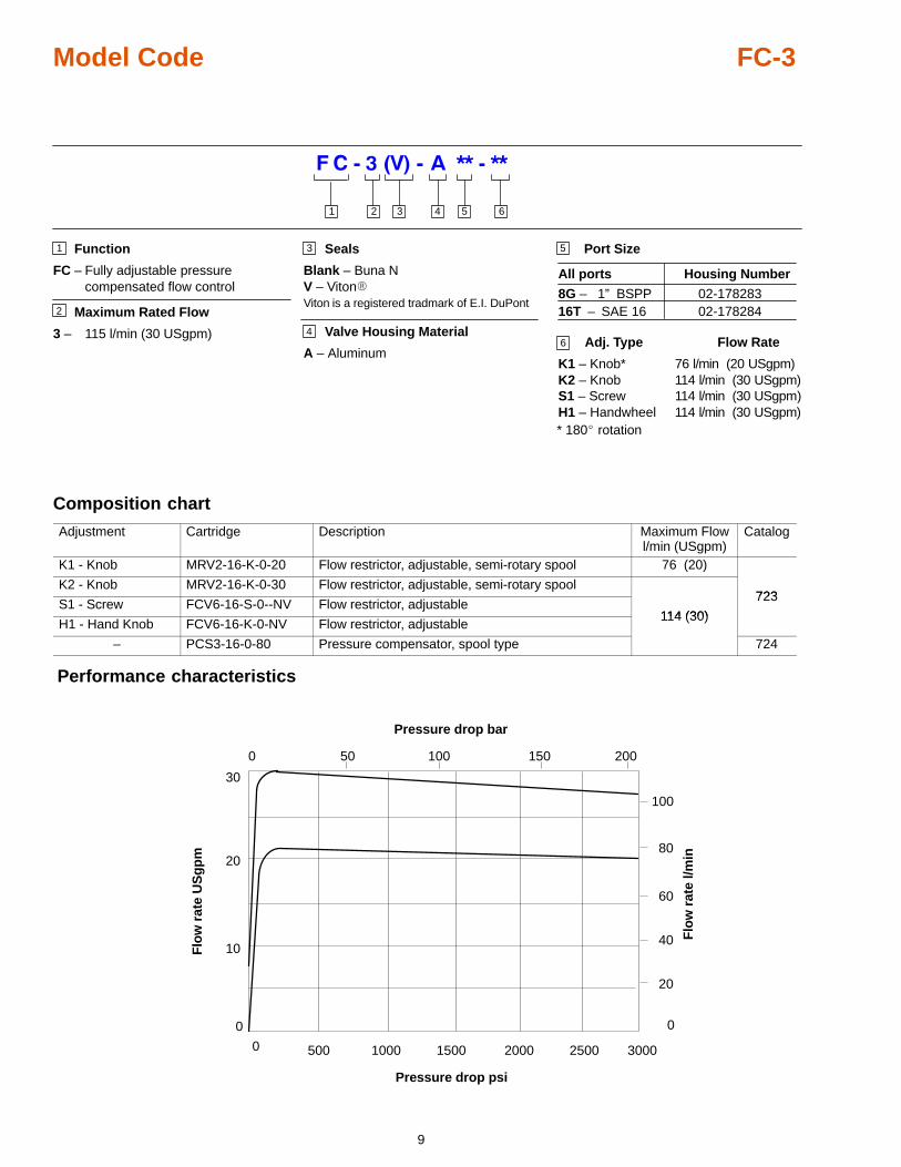
Model Code FC-3
Function
FC – Fully adjustable pressure compensated flow control
Maximum Rated Flow
3 – 115 l/min (30 USgpm)
5
3 4 5 61 2
1
2
3
46
Port Size
All ports Housing Number
8G – 1” BSPP16T – SAE 16
02-178283
Adj. Type Flow Rate
K1 – Knob* 76 l/min (20 USgpm)K2 – Knob 114 l/min (30 USgpm)S1 – Screw 114 l/min (30 USgpm)H1 – Handwheel 114 l/min (30 USgpm)
02-178284
* 180� rotation
Seals
Blank – Buna NV – Viton�Viton is a registered tradmark of E.I. DuPont
Valve Housing Material
A – Aluminum
Composition chart
Adjustment Cartridge Description Maximum Flowl/min (USgpm)
Catalog
K1 - Knob MRV2-16-K-0-20 Flow restrictor, adjustable, semi-rotary spool 76 (20)
K2 - Knob MRV2-16-K-0-30 Flow restrictor, adjustable, semi-rotary spool723
S1 - Screw FCV6-16-S-0--NV Flow restrictor, adjustable114 (30)
723
H1 - Hand Knob FCV6-16-K-0-NV Flow restrictor, adjustable114 (30)
– PCS3-16-0-80 Pressure compensator, spool type 724
Performance characteristics
0
10
0
20
40
60
80
0 500 1000 1500 2000 2500
50 100 1500 200
Pressure drop psi
Pressure drop bar
Flo
w r
ate
US
gp
m
Flo
w r
ate
l/min20
3000
100
30
10
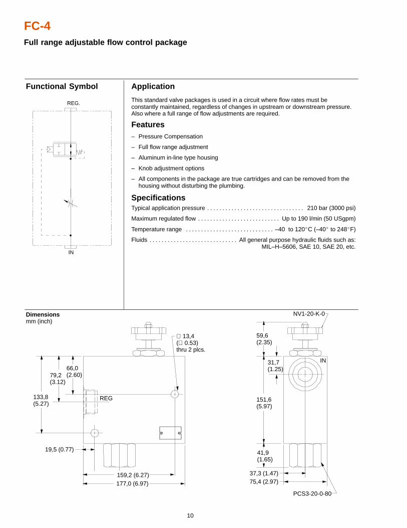
FC-4Full range adjustable flow control package
Application
This standard valve packages is used in a circuit where flow rates must beconstantly maintained, regardless of changes in upstream or downstream pressure.Also where a full range of flow adjustments are required.
Features– Pressure Compensation
– Full flow range adjustment
– Aluminum in-line type housing
– Knob adjustment options
– All components in the package are true cartridges and can be removed from the housing without disturbing the plumbing.
SpecificationsTypical application pressure 210 bar (3000 psi). . . . . . . . . . . . . . . . . . . . . . . . . . . . . . . .
Maximum regulated flow Up to 190 l/min (50 USgpm). . . . . . . . . . . . . . . . . . . . . . . . . . .
Temperature range –40 to 120�C (–40� to 248�F). . . . . . . . . . . . . . . . . . . . . . . . . . . . .
Fluids All general purpose hydraulic fluids such as:. . . . . . . . . . . . . . . . . . . . . . . . . . . . . MIL–H–5606, SAE 10, SAE 20, etc.
Dimensions mm (inch)
Functional Symbol
66,0(2.60)
19,5 (0.77)
59,6(2.35)
177,0 (6.97)
41,9(1.65)
151,6(5.97)
31,7(1.25)
75,4 (2.97)
79,2(3.12)
133,8(5.27)
∅ 13,4(∅ 0.53)thru 2 plcs.
REG
159,2 (6.27)
PCS3-20-0-80
NV1-20-K-0
IN
37,3 (1.47)
IN
REG.
11
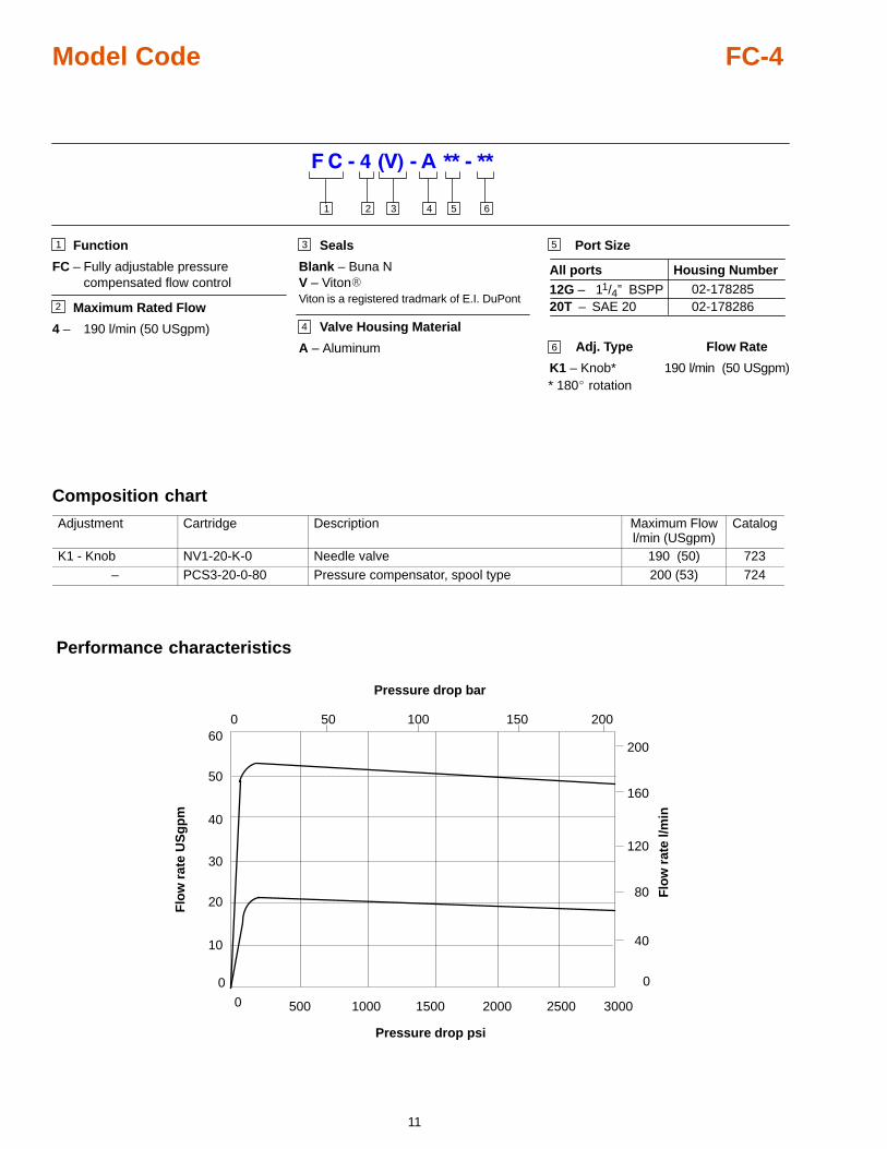
Model Code FC-4
Function
FC – Fully adjustable pressure compensated flow control
Maximum Rated Flow
4 – 190 l/min (50 USgpm)
5
3 4 5 61 2
1
2
3
4
6
Port Size
All ports Housing Number
12G – 11/4” BSPP20T – SAE 20
02-178285
Adj. Type Flow Rate
K1 – Knob* 190 l/min (50 USgpm)
02-178286
* 180� rotation
Seals
Blank – Buna NV – Viton�Viton is a registered tradmark of E.I. DuPont
Valve Housing Material
A – Aluminum
Composition chart
Adjustment Cartridge Description Maximum Flowl/min (USgpm)
Catalog
K1 - Knob NV1-20-K-0 Needle valve 190 (50) 723– PCS3-20-0-80 Pressure compensator, spool type 200 (53) 724
Performance characteristics
0
10
0
40
80
120
160
0 500 1000 1500 2000 2500
50 100 1500 200
Pressure drop psi
Pressure drop bar
Flo
w r
ate
US
gp
m
Flo
w r
ate
l/min
20
3000
30
40
50
60200
12
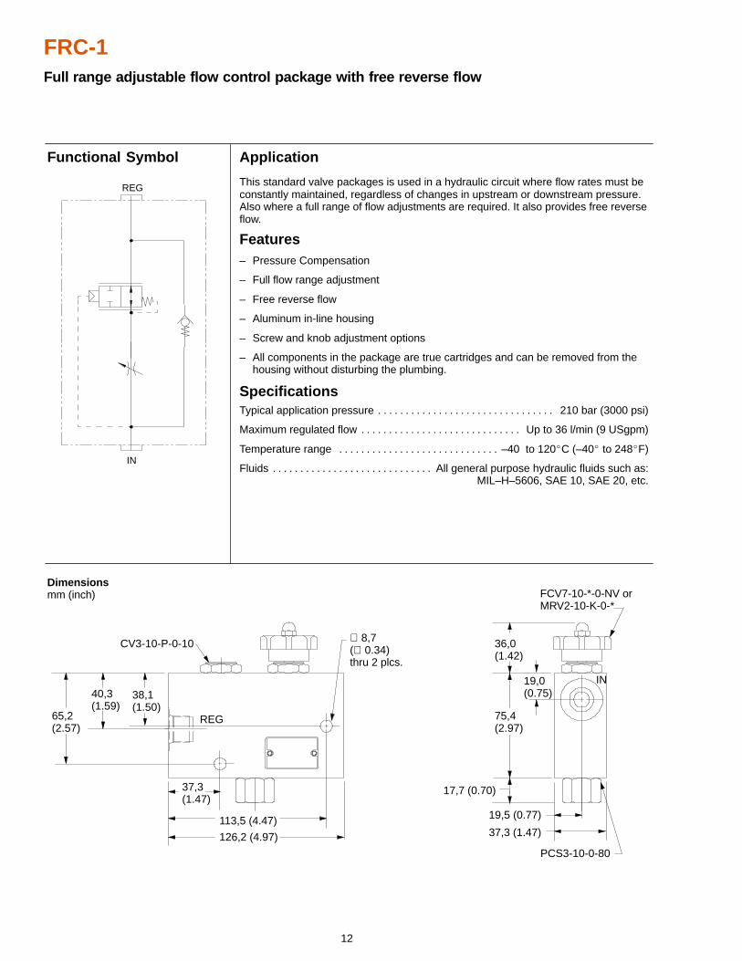
FRC-1Full range adjustable flow control package with free reverse flow
Application
This standard valve packages is used in a hydraulic circuit where flow rates must beconstantly maintained, regardless of changes in upstream or downstream pressure.Also where a full range of flow adjustments are required. It also provides free reverseflow.
Features– Pressure Compensation
– Full flow range adjustment
– Free reverse flow
– Aluminum in-line housing
– Screw and knob adjustment options
– All components in the package are true cartridges and can be removed from the housing without disturbing the plumbing.
SpecificationsTypical application pressure 210 bar (3000 psi). . . . . . . . . . . . . . . . . . . . . . . . . . . . . . . .
Maximum regulated flow Up to 36 l/min (9 USgpm). . . . . . . . . . . . . . . . . . . . . . . . . . . . .
Temperature range –40 to 120�C (–40� to 248�F). . . . . . . . . . . . . . . . . . . . . . . . . . . . .
Fluids All general purpose hydraulic fluids such as:. . . . . . . . . . . . . . . . . . . . . . . . . . . . . MIL–H–5606, SAE 10, SAE 20, etc.
Dimensions mm (inch)
Functional Symbol
19,5 (0.77)
65,2(2.57)
40,3(1.59)
38,1(1.50)
36,0(1.42)
17,7 (0.70)
19,0(0.75)
37,3(1.47)
113,5 (4.47)
126,2 (4.97)
75,4(2.97)
∅ 8,7(∅ 0.34)thru 2 plcs.
REG
IN
CV3-10-P-0-10
FCV7-10-*-0-NV orMRV2-10-K-0-*
PCS3-10-0-80
37,3 (1.47)
REG
IN
13
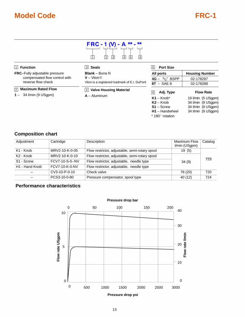
Model Code FRC-1
Function
FRC–Fully adjustable pressure compensated flow control with reverse flow check
Maximum Rated Flow
1 – 34 l/min (9 USgpm)
5
3 4 5 61 2
1
2
3
46
Port Size
All ports Housing Number
4G – 1/2” BSPP8T – SAE 8
02-178287
Adj. Type Flow Rate
K1 – Knob* 19 l/min (5 USgpm)K2 – Knob 34 l/min (9 USgpm)S1 – Screw 34 l/min (9 USgpm)H1 – Handwheel 34 l/min (9 USgpm)
02-178288
* 180� rotation
Seals
Blank – Buna NV – Viton�Viton is a registered tradmark of E.I. DuPont
Valve Housing Material
A – Aluminum
Composition chart
Adjustment Cartridge Description Maximum Flowl/min (USgpm)
Catalog
K1 - Knob MRV2-10-K-0-05 Flow restrictor, adjustable, semi-rotary spool 19 (5)
K2 - Knob MRV2-10-K-0-10 Flow restrictor, adjustable, semi-rotary spool723
S1 - Screw FCV7-10-S-0--NV Flow restrictor, adjustable, needle type 34 (9)723
H1 - Hand Knob FCV7-10-K-0-NV Flow restrictor, adjustable, needle type( )
– CV3-10-P-0-10 Check valve 76 (20) 720– PCS3-10-0-80 Pressure compensator, spool type 40 (12) 724
Performance characteristics
0
5
10
0
10
20
30
40
0 500 1000 1500 2000 2500
50 100 1500 200
Pressure drop psi
Pressure drop bar
Flo
w r
ate
US
gp
m
Flo
w r
ate
l/min
3000
14
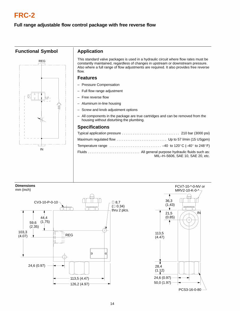
FRC-2Full range adjustable flow control package with free reverse flow
Application
This standard valve packages is used in a hydraulic circuit where flow rates must beconstantly maintained, regardless of changes in upstream or downstream pressure.Also where a full range of flow adjustments are required. It also provides free reverseflow.
Features– Pressure Compensation
– Full flow range adjustment
– Free reverse flow
– Aluminum in-line housing
– Screw and knob adjustment options
– All components in the package are true cartridges and can be removed from the housing without disturbing the plumbing.
SpecificationsTypical application pressure 210 bar (3000 psi). . . . . . . . . . . . . . . . . . . . . . . . . . . . . . . .
Maximum regulated flow Up to 57 l/min (15 USgpm). . . . . . . . . . . . . . . . . . . . . . . . . . . .
Temperature range –40 to 120�C (–40� to 248�F). . . . . . . . . . . . . . . . . . . . . . . . . . . . .
Fluids All general purpose hydraulic fluids such as:. . . . . . . . . . . . . . . . . . . . . . . . . . . . . MIL–H–5606, SAE 10, SAE 20, etc.
Dimensions mm (inch)
Functional Symbol
59,6(2.35)
44,4(1.75)
113,5 (4.47)
28,4(1.12)
21,5(0.85)
36,3(1.43)
126,2 (4.97)
24,6 (0.97)
50,0 (1.97)
103,3(4.07)
113,5(4.47)
PCS3-16-0-80
IN
REG
CV3-10-P-0-10 ∅ 8,7(∅ 0.34)thru 2 plcs.
24,6 (0.97)
FCV7-10-*-0-NV orMRV2-10-K-0-*
REG
IN
15
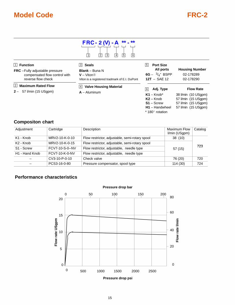
Model Code FRC-2
Function
FRC –Fully adjustable pressure compensated flow control with reverse flow check
Maximum Rated Flow
2 – 57 l/min (15 USgpm)
5
3 4 5 61 2
1
2
3
46
Port SizeAll ports Housing Number
6G – 3/4” BSPP12T – SAE 12
02-178289
Adj. Type Flow Rate
K1 – Knob* 38 l/min (10 USgpm)K2 – Knob 57 l/min (15 USgpm)S1 – Screw 57 l/min (15 USgpm)H1 – Handwheel 57 l/min (15 USgpm)
02-178290
* 180� rotation
Seals
Blank – Buna NV – Viton�Viton is a registered tradmark of E.I. DuPont
Valve Housing Material
A – Aluminum
Compositon chart
Adjustment Cartridge Description Maximum Flowl/min (USgpm)
Catalog
K1 - Knob MRV2-10-K-0-10 Flow restrictor, adjustable, semi-rotary spool 38 (10)
K2 - Knob MRV2-10-K-0-15 Flow restrictor, adjustable, semi-rotary spool723
S1 - Screw FCV7-10-S-0--NV Flow restrictor, adjustable, needle type 57 (15)723
H1 - Hand Knob FCV7-10-K-0-NV Flow restrictor, adjustable, needle type( )
– CV3-10-P-0-10 Check valve 76 (20) 720– PCS3-16-0-80 Pressure compensator, spool type 114 (30) 724
Performance characteristics
0
5
10
0
20
40
60
80
0 500 1000 1500 2000 2500
50 100 1500 200
Pressure drop psi
Pressure drop bar
Flo
w r
ate
US
gp
m
Flo
w r
ate
l/min
15
20
16
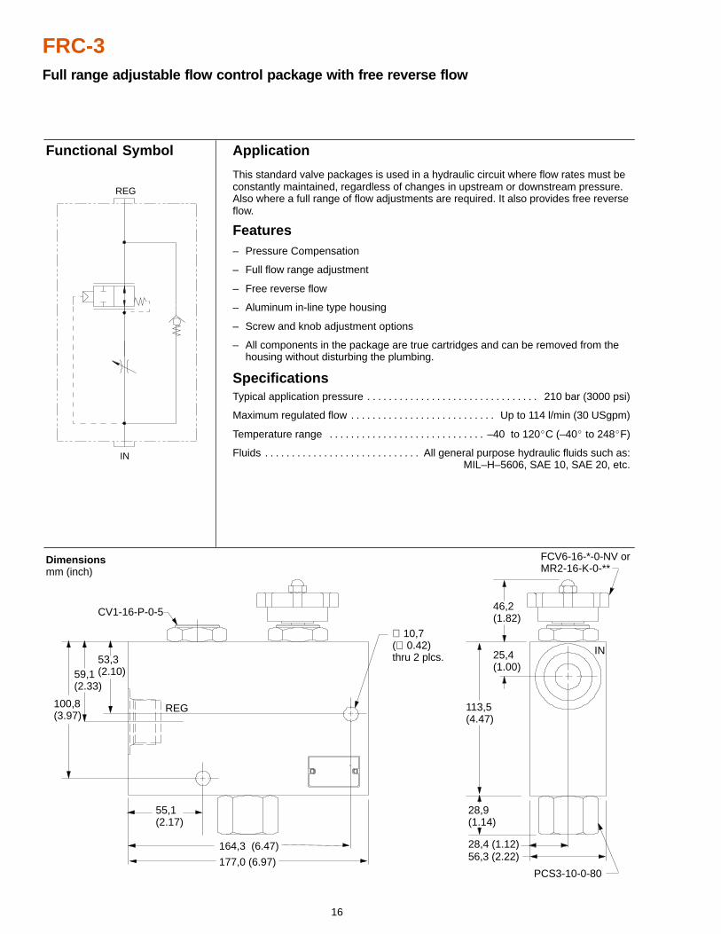
FRC-3Full range adjustable flow control package with free reverse flow
Application
This standard valve packages is used in a hydraulic circuit where flow rates must beconstantly maintained, regardless of changes in upstream or downstream pressure.Also where a full range of flow adjustments are required. It also provides free reverseflow.
Features– Pressure Compensation
– Full flow range adjustment
– Free reverse flow
– Aluminum in-line type housing
– Screw and knob adjustment options
– All components in the package are true cartridges and can be removed from the housing without disturbing the plumbing.
SpecificationsTypical application pressure 210 bar (3000 psi). . . . . . . . . . . . . . . . . . . . . . . . . . . . . . . .
Maximum regulated flow Up to 114 l/min (30 USgpm). . . . . . . . . . . . . . . . . . . . . . . . . . .
Temperature range –40 to 120�C (–40� to 248�F). . . . . . . . . . . . . . . . . . . . . . . . . . . . .
Fluids All general purpose hydraulic fluids such as:. . . . . . . . . . . . . . . . . . . . . . . . . . . . . MIL–H–5606, SAE 10, SAE 20, etc.
Dimensions mm (inch)
Functional Symbol
REG
IN
113,5(4.47)
28,4 (1.12)
46,2(1.82)
59,1(2.33)
55,1(2.17)
28,9(1.14)
56,3 (2.22)177,0 (6.97)
164,3 (6.47)
100,8(3.97)
53,3(2.10)
25,4(1.00)
CV1-16-P-0-5
FCV6-16-*-0-NV orMR2-16-K-0-**
PCS3-10-0-80
∅ 10,7(∅ 0.42)thru 2 plcs.
REG
IN
17
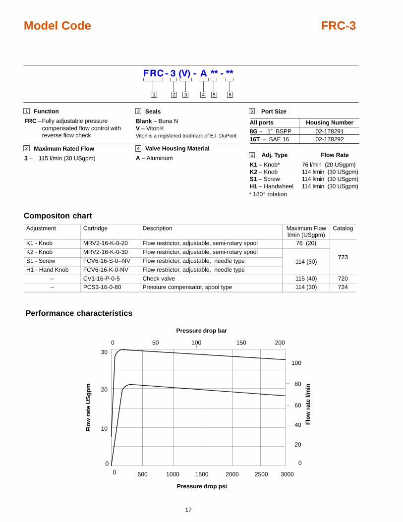
Model Code FRC-3
Maximum Rated Flow
3 – 115 l/min (30 USgpm)
5
3 4 5 61 2
1
2
3
4
6
Port Size
All ports Housing Number
8G – 1” BSPP16T – SAE 16
02-178291
Adj. Type Flow Rate
K1 – Knob* 76 l/min (20 USgpm)K2 – Knob 114 l/min (30 USgpm)S1 – Screw 114 l/min (30 USgpm)H1 – Handwheel 114 l/min (30 USgpm)
02-178292
* 180� rotation
Seals
Blank – Buna NV – Viton�Viton is a registered tradmark of E.I. DuPont
Valve Housing Material
A – Aluminum
Function
FRC –Fully adjustable pressure compensated flow control with reverse flow check
Compositon chart
Adjustment Cartridge Description Maximum Flowl/min (USgpm)
Catalog
K1 - Knob MRV2-16-K-0-20 Flow restrictor, adjustable, semi-rotary spool 76 (20)
K2 - Knob MRV2-16-K-0-30 Flow restrictor, adjustable, semi-rotary spool723
S1 - Screw FCV6-16-S-0--NV Flow restrictor, adjustable, needle type 114 (30)723
H1 - Hand Knob FCV6-16-K-0-NV Flow restrictor, adjustable, needle type( )
– CV1-16-P-0-5 Check valve 115 (40) 720– PCS3-16-0-80 Pressure compensator, spool type 114 (30) 724
Performance characteristics
0
10
0
20
40
60
80
0 500 1000 1500 2000 2500
50 100 1500 200
Pressure drop psi
Pressure drop bar
Flo
w r
ate
US
gp
m
Flo
w r
ate
l/min20
3000
100
30
18
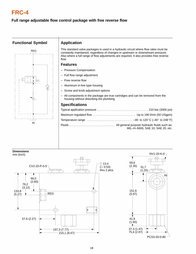
FRC-4Full range adjustable flow control package with free reverse flow
Application
This standard valve packages is used in a hydraulic circuit where flow rates must beconstantly maintained, regardless of changes in upstream or downstream pressure.Also where a full range of flow adjustments are required. It also provides free reverseflow.
Features– Pressure Compensation
– Full flow range adjustment
– Free reverse flow
– Aluminum in-line type housing
– Screw and knob adjustment options
– All components in the package are true cartridges and can be removed from the housing without disturbing the plumbing.
SpecificationsTypical application pressure 210 bar (3000 psi). . . . . . . . . . . . . . . . . . . . . . . . . . . . . . . . . . .
Maximum regulated flow Up to 190 l/min (50 USgpm). . . . . . . . . . . . . . . . . . . . . . . . . . . . .
Temperature range –40 to 120�C (–40� to 248�F). . . . . . . . . . . . . . . . . . . . . . . . . . . . . . .
Fluids All general purpose hydraulic fluids such as:. . . . . . . . . . . . . . . . . . . . . . . . . . . . . . . MIL–H–5606, SAE 10, SAE 20, etc.
Dimensions mm (inch)
Functional Symbol
66,0(2.60)
37,3 (1.47)
59,6(2.35)
41,9(1.65)
151,6(5.97)
31,7(1.25)
57,6 (2.27)
197,3 (7.77)215,1 (8.47) 75,4 (2.97)
79,2(3.12)
133,8(5.27)
∅ 13,4(∅ 0.53)thru 2 plcs.
IN
REG
CV2-20-P-0-5
NV1-20-K-0
PCS3-20-0-80
REG
IN
19
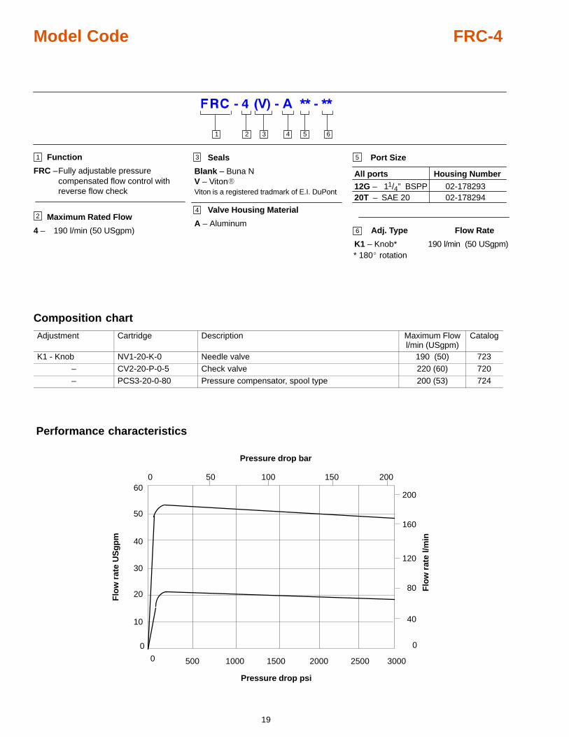
Model Code FRC-4
Maximum Rated Flow
4 – 190 l/min (50 USgpm)
5
3 4 5 61 2
1
2
3
4
6
Port Size
All ports Housing Number
12G – 11/4” BSPP20T – SAE 20
02-178293
Adj. Type Flow Rate
K1 – Knob* 190 l/min (50 USgpm)
02-178294
* 180� rotation
Seals
Blank – Buna NV – Viton�Viton is a registered tradmark of E.I. DuPont
Valve Housing Material
A – Aluminum
Function
FRC –Fully adjustable pressure compensated flow control with reverse flow check
Composition chart
Adjustment Cartridge Description Maximum Flowl/min (USgpm)
Catalog
K1 - Knob NV1-20-K-0 Needle valve 190 (50) 723– CV2-20-P-0-5 Check valve 220 (60) 720– PCS3-20-0-80 Pressure compensator, spool type 200 (53) 724
Performance characteristics
0
10
0
40
80
120
160
0 500 1000 1500 2000 2500
50 100 1500 200
Pressure drop psi
Pressure drop bar
Flo
w r
ate
US
gp
m
Flo
w r
ate
l/min
20
3000
30
40
50
60200
20
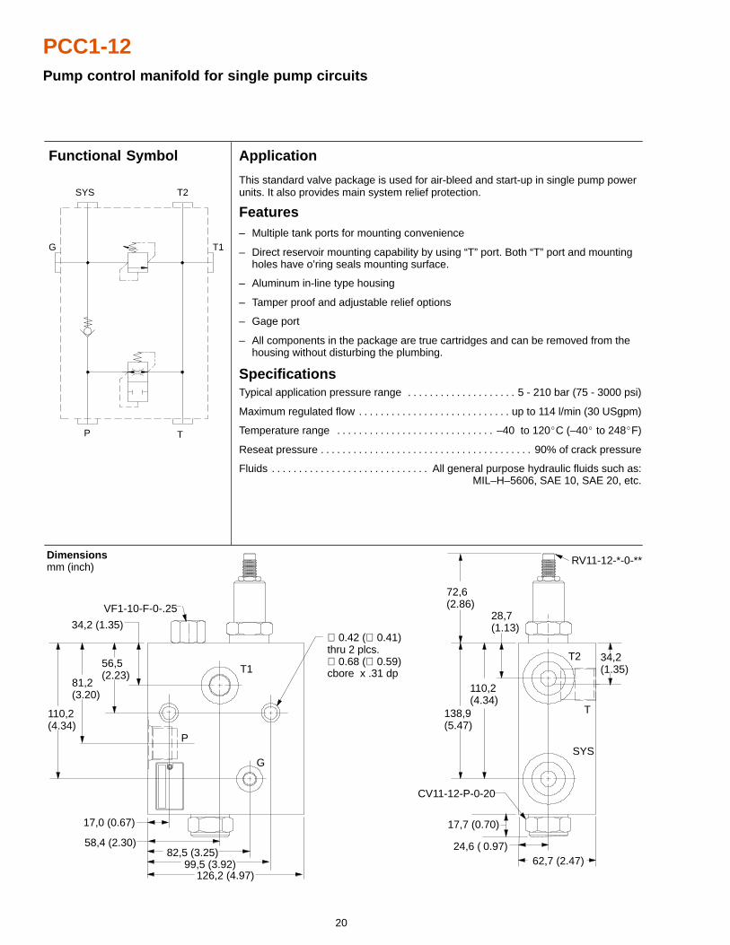
PCC1-12Pump control manifold for single pump circuits
Application
This standard valve package is used for air-bleed and start-up in single pump powerunits. It also provides main system relief protection.
Features– Multiple tank ports for mounting convenience
– Direct reservoir mounting capability by using “T” port. Both “T” port and mounting holes have o’ring seals mounting surface.
– Aluminum in-line type housing
– Tamper proof and adjustable relief options
– Gage port
– All components in the package are true cartridges and can be removed from the housing without disturbing the plumbing.
SpecificationsTypical application pressure range 5 - 210 bar (75 - 3000 psi). . . . . . . . . . . . . . . . . . . .
Maximum regulated flow up to 114 l/min (30 USgpm). . . . . . . . . . . . . . . . . . . . . . . . . . . .
Temperature range –40 to 120�C (–40� to 248�F). . . . . . . . . . . . . . . . . . . . . . . . . . . . .
Reseat pressure 90% of crack pressure. . . . . . . . . . . . . . . . . . . . . . . . . . . . . . . . . . . . . . .
Fluids All general purpose hydraulic fluids such as:. . . . . . . . . . . . . . . . . . . . . . . . . . . . . MIL–H–5606, SAE 10, SAE 20, etc.
Dimensions mm (inch)
Functional Symbol
VF1-10-F-0-.25
RV11-12-*-0-**
CV11-12-P-0-20
110,2(4.34)
81,2(3.20)
56,5(2.23)
34,2 (1.35)
T1
P
G
126,2 (4.97)99,5 (3.92)
82,5 (3.25)58,4 (2.30)
17,0 (0.67)
62,7 (2.47)24,6 ( 0.97)
17,7 (0.70)
138,9(5.47)
110,2(4.34)
28,7(1.13)
72,6(2.86)
34,2(1.35)
SYS
T
T2
∅ 0.42 (∅ 0.41)thru 2 plcs.∅ 0.68 (∅ 0.59)cbore x .31 dp
T1
T2SYS
P
G
T
21
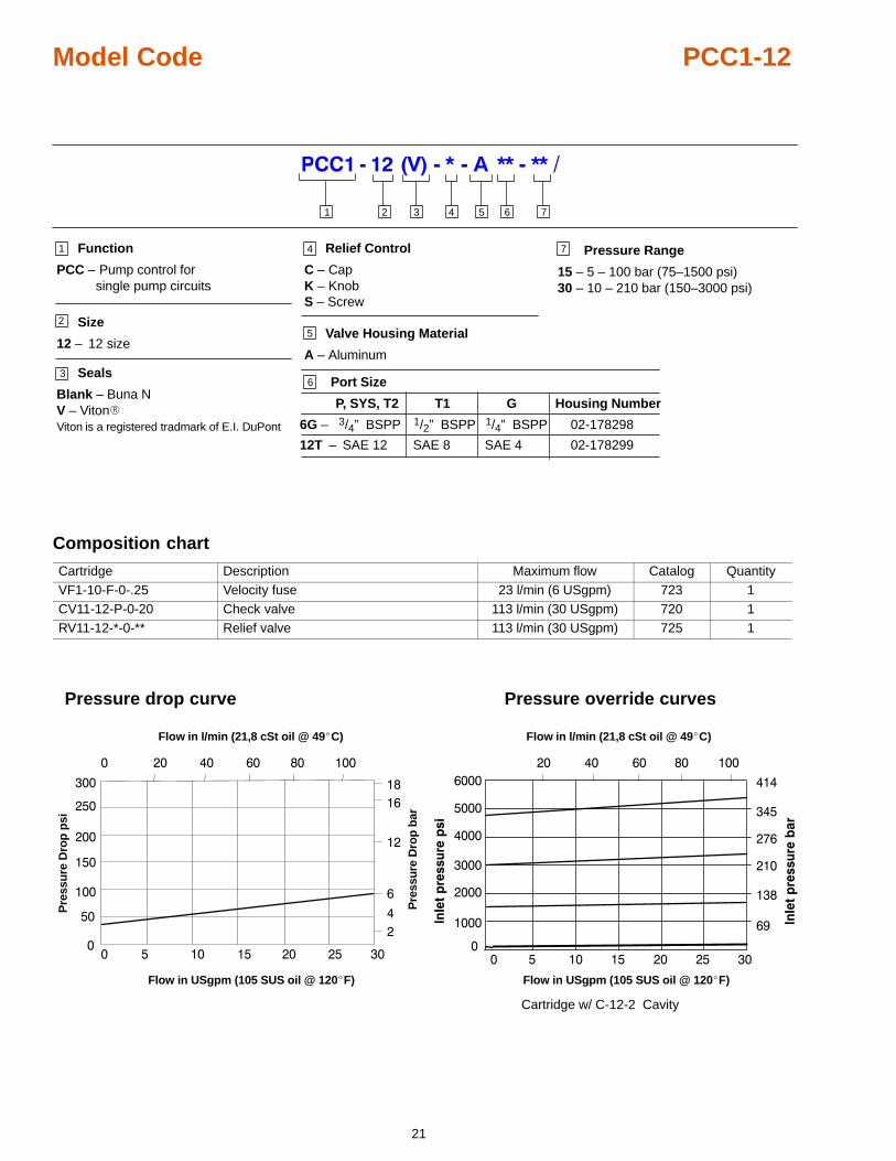
Model Code PCC1-12
Size
12 – 12 size5
3 4 5 61 2
1
2
3
4
6 Port Size
P, SYS, T2 Housing Number
6G – 3/4” BSPP
12T – SAE 12
02-178298
Pressure Range
15 – 5 – 100 bar (75–1500 psi)30 – 10 – 210 bar (150–3000 psi)
02-178299
Relief Control
C – CapK – KnobS – Screw
Function
PCC – Pump control forsingle pump circuits
7
Valve Housing Material
A – Aluminum
7
Seals
Blank – Buna NV – Viton�Viton is a registered tradmark of E.I. DuPont
T1
1/2” BSPP
SAE 8
G
1/4” BSPP
SAE 4
Composition chart
Cartridge Description Maximum flow Catalog QuantityVF1-10-F-0-.25 Velocity fuse 23 l/min (6 USgpm) 723 1CV11-12-P-0-20 Check valve 113 l/min (30 USgpm) 720 1RV11-12-*-0-** Relief valve 113 l/min (30 USgpm) 725 1
Pressure drop curve
�� � �� �� �� �� ��
�
�����������
��
���
���
���
Flow in l/min (21,8 cSt oil @ 49�C)
Flow in USgpm (105 SUS oil @ 120�F)
�
�
��
��
��
Pre
ssu
re D
rop
psi
Pre
ssu
re D
rop
bar
Pressure override curves
���
���
����
����
����
����
�
� � �� �� �� �� ��
�
��
���
���
��������� ��
Flow in l/min (21,8 cSt oil @ 49�C)
Flow in USgpm (105 SUS oil @ 120�F)
����
���
��
����
�
����
���
��
����
�
�
Cartridge w/ C-12-2 Cavity
���
���
����
����

22
PCC1-16Pump control manifold for single pump circuits
Application
This standard valve package is used for air-bleed and start-up in single pump powerunits. It also provides main system relief protection.
Features– Multiple tank ports for mounting convenience
– Direct reservoir mounting capability by using “T” port. Both “T” port and mounting holes have o’ring seals mounting surface.
– Aluminum in-line type housing
– Tamper proof and adjustable relief options
– Gage port
– All components in the package are true cartridges and can be removed from the housing without disturbing the plumbing.
SpecificationsTypical application pressure range 10 - 210 bar (150 - 3000 psi). . . . . . . . . . . . . . . . . .
Maximum regulated flow up to 228 l/min (60 USgpm). . . . . . . . . . . . . . . . . . . . . . . . . . .
Temperature range –40 to 120�C (–40� to 248�F). . . . . . . . . . . . . . . . . . . . . . . . . . . . .
Reseat pressure 90% of crack pressure. . . . . . . . . . . . . . . . . . . . . . . . . . . . . . . . . . . . . . .
Fluids All general purpose hydraulic fluids such as:. . . . . . . . . . . . . . . . . . . . . . . . . . . . . MIL–H–5606, SAE 10, SAE 20, etc.
Dimensions mm (inch)
T1
T2SYS
P
G
T
Functional Symbol
VF1-16-F-0-.25
RV5-16-*-0-**-30/
CV2-20-P-0-30
T1
P
GSYS
T
T2
∅ 0,42 (∅ 0.41)thru 2 plcs.∅ 0.68 (∅ 0.59)cbore x .31 dp
119,8(4.72)
81,2(3.20)
56,1(2.21)
29,2 (1.15)
15,2 ( 0.60)
66,0 (2.60)97,7 (3.85)
116,8 (4.60)151,6 (5.97)
63,5(2.50)
25,4(1.00)
13,4 (0.53)
33,5 (1.32)75,4 (2.97)
29,2(1.15)
151,6(5.97)
119,8(4.72)
23
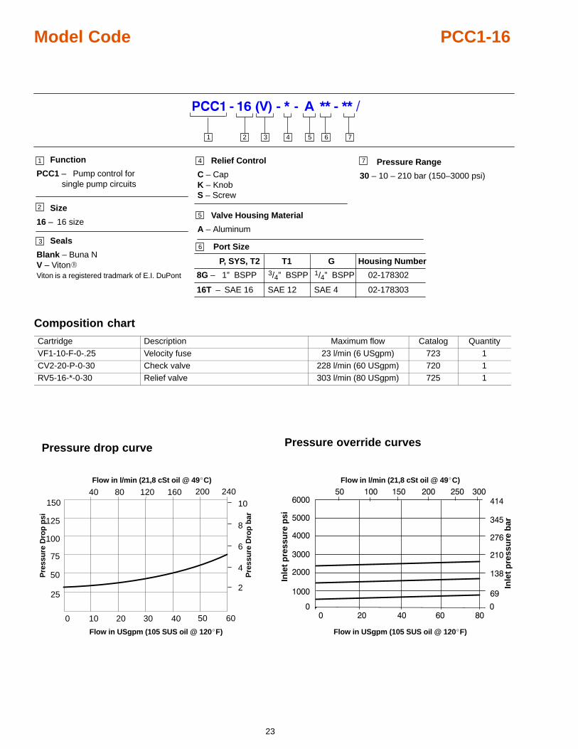
Model Code PCC1-16
Size
16 – 16 size5
3 4 5 61 2
1
2
3
4
6 Port Size
P, SYS, T2 Housing Number
8G – 1” BSPP
16T – SAE 16
02-178302
Pressure Range
30 – 10 – 210 bar (150–3000 psi)
02-178303
Relief Control
C – CapK – KnobS – Screw
Function
PCC1 – Pump control forsingle pump circuits
7
Valve Housing Material
A – Aluminum
7
Seals
Blank – Buna NV – Viton�Viton is a registered tradmark of E.I. DuPont
T1
3/4” BSPP
SAE 12
G
1/4” BSPP
SAE 4
Composition chart
Cartridge Description Maximum flow Catalog QuantityVF1-10-F-0-.25 Velocity fuse 23 l/min (6 USgpm) 723 1CV2-20-P-0-30 Check valve 228 l/min (60 USgpm) 720 1RV5-16-*-0-30 Relief valve 303 l/min (80 USgpm) 725 1
Pressure drop curve Pressure override curves
���
���
����
����
����
����
����
����
�
� �� �� ��
�
��
���
���
�������������� ���
Flow in l/min (21,8 cSt oil @ 49�C)
Inle
t p
ress
ure
psi
Inle
t p
ress
ure
bar
Flow in USgpm (105 SUS oil @ 120�F)
�
��10 20 30 400
25
50
75
100
125
40 80150
50 60
2
4
6
8
10120 160 200 240
Flow in l/min (21,8 cSt oil @ 49�C)
Flow in USgpm (105 SUS oil @ 120�F)
Pre
ssu
re D
rop
psi
Pre
ssu
re D
rop
bar
24
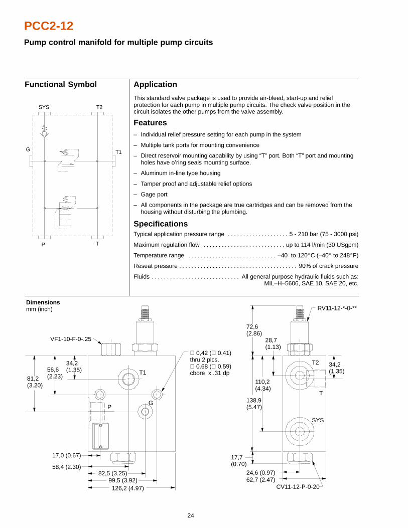
PCC2-12Pump control manifold for multiple pump circuits
62,7 (2.47)
Application
This standard valve package is used to provide air-bleed, start-up and reliefprotection for each pump in multiple pump circuits. The check valve position in thecircuit isolates the other pumps from the valve assembly.
Features– Individual relief pressure setting for each pump in the system
– Multiple tank ports for mounting convenience
– Direct reservoir mounting capability by using “T” port. Both “T” port and mounting holes have o’ring seals mounting surface.
– Aluminum in-line type housing
– Tamper proof and adjustable relief options
– Gage port
– All components in the package are true cartridges and can be removed from the housing without disturbing the plumbing.
SpecificationsTypical application pressure range 5 - 210 bar (75 - 3000 psi). . . . . . . . . . . . . . . . . . . .
Maximum regulation flow up to 114 l/min (30 USgpm). . . . . . . . . . . . . . . . . . . . . . . . . . .
Temperature range –40 to 120�C (–40� to 248�F). . . . . . . . . . . . . . . . . . . . . . . . . . . . .
Reseat pressure 90% of crack pressure. . . . . . . . . . . . . . . . . . . . . . . . . . . . . . . . . . . . . . .
Fluids All general purpose hydraulic fluids such as:. . . . . . . . . . . . . . . . . . . . . . . . . . . . . MIL–H–5606, SAE 10, SAE 20, etc.
Dimensions mm (inch)
Functional Symbol
CV11-12-P-0-20
VF1-10-F-0-.25
81,2(3.20)
56,6(2.23)
34,2(1.35) T1
PG
SYS
T
T2 34,2(1.35)
138,9(5.47)
17,7(0.70)
72,6(2.86)
110,2(4.34)
28,7(1.13)
24,6 (0.97)
17,0 (0.67)
58,4 (2.30)82,5 (3.25)
99,5 (3.92)126,2 (4.97)
RV11-12-*-0-**
∅ 0,42 (∅ 0.41)thru 2 plcs.∅ 0.68 (∅ 0.59)cbore x .31 dp
G
P T
T1
T2SYS
25
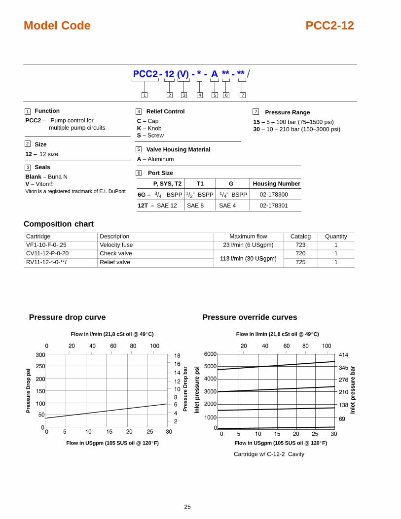
Model Code PCC2-12
Size
12 – 12 size5
3 4 5 61 2
1
2
3
4
6 Port Size
P, SYS, T2 Housing Number
6G –
12T – SAE 12
02-178300
Pressure Range
15 – 5 – 100 bar (75–1500 psi)30 – 10 – 210 bar (150–3000 psi)
02-178301
Relief Control
C – CapK – KnobS – Screw
Function
PCC2 – Pump control formultiple pump circuits
7
Valve Housing Material
A – Aluminum
7
Seals
Blank – Buna NV – Viton�Viton is a registered tradmark of E.I. DuPont
T1
1/2” BSPP
SAE 8
G
1/4” BSPP
SAE 4
3/4” BSPP
Composition chart
Cartridge Description Maximum flow Catalog QuantityVF1-10-F-0-.25 Velocity fuse 23 l/min (6 USgpm) 723 1CV11-12-P-0-20 Check valve
113 l/min (30 USgpm)720 1
RV11-12-*-0-**/ Relief valve113 l/min (30 USgpm)
725 1
Pressure drop curve
�� � �� �� �� �� ��
�
�����������
��
���
���
���
���
���
Flow in l/min (21,8 cSt oil @ 49�C)
Flow in USgpm (105 SUS oil @ 120�F)
�
�
�
��
��
��
��
��
Pre
ssu
re D
rop
psi
Pre
ssu
re D
rop
bar
Pressure override curves
���
���
����
����
����
����
����
����
�
� � �� �� �� �� ��
�
��
���
���
��������� ��
Flow in l/min (21,8 cSt oil @ 49�C)
Flow in USgpm (105 SUS oil @ 120�F)
����
���
��
����
�
����
���
��
����
�
�
Cartridge w/ C-12-2 Cavity
26
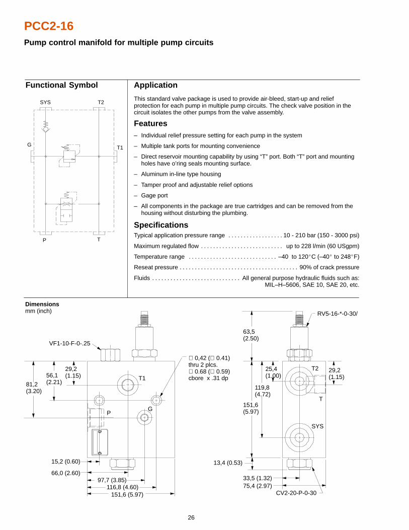
PCC2-16Pump control manifold for multiple pump circuits
Application
This standard valve package is used to provide air-bleed, start-up and reliefprotection for each pump in multiple pump circuits. The check valve position in thecircuit isolates the other pumps from the valve assembly.
Features– Individual relief pressure setting for each pump in the system
– Multiple tank ports for mounting convenience
– Direct reservoir mounting capability by using “T” port. Both “T” port and mounting holes have o’ring seals mounting surface.
– Aluminum in-line type housing
– Tamper proof and adjustable relief options
– Gage port
– All components in the package are true cartridges and can be removed from the housing without disturbing the plumbing.
SpecificationsTypical application pressure range 10 - 210 bar (150 - 3000 psi). . . . . . . . . . . . . . . . . .
Maximum regulated flow up to 228 l/min (60 USgpm). . . . . . . . . . . . . . . . . . . . . . . . . . .
Temperature range –40 to 120�C (–40� to 248�F). . . . . . . . . . . . . . . . . . . . . . . . . . . . .
Reseat pressure 90% of crack pressure. . . . . . . . . . . . . . . . . . . . . . . . . . . . . . . . . . . . . . .
Fluids All general purpose hydraulic fluids such as:. . . . . . . . . . . . . . . . . . . . . . . . . . . . . MIL–H–5606, SAE 10, SAE 20, etc.
Functional Symbol
G
P T
T1
T2SYS
75,4 (2.97)
Dimensions mm (inch)
CV2-20-P-0-30
VF1-10-F-0-.25
81,2(3.20)
56,1(2.21)
29,2(1.15) T1
PG
SYS
T
T2 29,2(1.15)
151,6(5.97)
13,4 (0.53)
119,8(4.72)
25,4(1.00)
33,5 (1.32)
15,2 (0.60)
66,0 (2.60)97,7 (3.85)
116,8 (4.60)151,6 (5.97)
RV5-16-*-0-30/
∅ 0,42 (∅ 0.41)thru 2 plcs.∅ 0.68 (∅ 0.59)cbore x .31 dp
63,5(2.50)
27
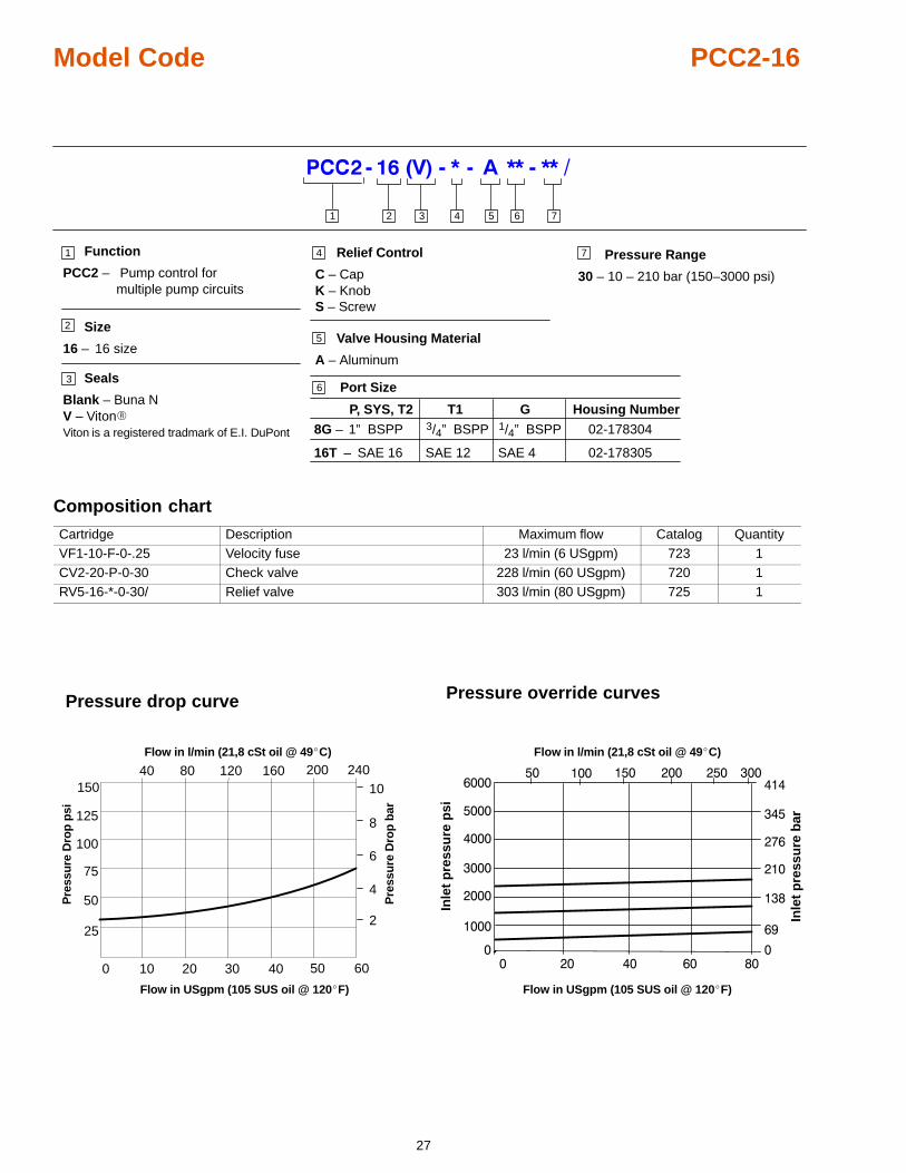
Model Code PCC2-16
Size
16 – 16 size5
3 4 5 61 2
1
2
3
4
6 Port Size
P, SYS, T2 Housing Number
8G –
16T – SAE 16
02-178304
Pressure Range
30 – 10 – 210 bar (150–3000 psi)
02-178305
Relief Control
C – CapK – KnobS – Screw
Function
PCC2 – Pump control formultiple pump circuits
7
Valve Housing Material
A – Aluminum
7
Seals
Blank – Buna NV – Viton�Viton is a registered tradmark of E.I. DuPont
T1
SAE 12
G
1/4” BSPP
SAE 4
1” BSPP 3/4” BSPP
Composition chart
Cartridge Description Maximum flow Catalog QuantityVF1-10-F-0-.25 Velocity fuse 23 l/min (6 USgpm) 723 1CV2-20-P-0-30 Check valve 228 l/min (60 USgpm) 720 1RV5-16-*-0-30/ Relief valve 303 l/min (80 USgpm) 725 1
Pressure drop curve Pressure override curves
���
���
����
����
����
����
����
����
�
� �� �� ��
�
��
���
���
�������������� ���
Flow in l/min (21,8 cSt oil @ 49�C)
Inle
t p
ress
ure
psi
Inle
t p
ress
ure
bar
Flow in USgpm (105 SUS oil @ 120�F)
�
��10 20 30 400
25
50
75
100
125
40 80150
50 60
2
4
6
8
10120 160 200 240
Flow in l/min (21,8 cSt oil @ 49�C)
Flow in USgpm (105 SUS oil @ 120�F)
Pre
ssu
re D
rop
psi
Pre
ssu
re D
rop
bar
28
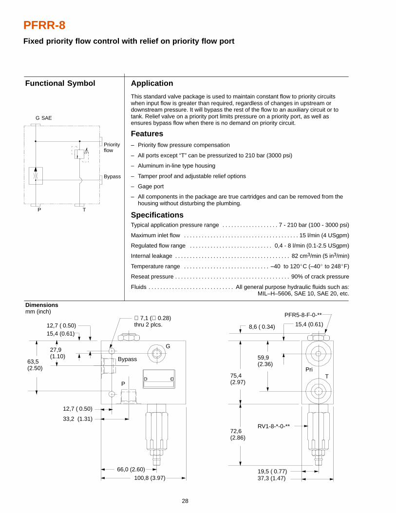
PFRR-8Fixed priority flow control with relief on priority flow port
Application
This standard valve package is used to maintain constant flow to priority circuitswhen input flow is greater than required, regardless of changes in upstream ordownstream pressure. It will bypass the rest of the flow to an auxiliary circuit or totank. Relief valve on a priority port limits pressure on a priority port, as well asensures bypass flow when there is no demand on priority circuit.
Features– Priority flow pressure compensation
– All ports except “T” can be pressurized to 210 bar (3000 psi)
– Aluminum in-line type housing
– Tamper proof and adjustable relief options
– Gage port
– All components in the package are true cartridges and can be removed from the housing without disturbing the plumbing.
SpecificationsTypical application pressure range 7 - 210 bar (100 - 3000 psi). . . . . . . . . . . . . . . . . . .
Maximum inlet flow 15 l/min (4 USgpm). . . . . . . . . . . . . . . . . . . . . . . . . . . . . . . . . . . . . . .
Regulated flow range 0,4 - 8 l/min (0.1-2.5 USgpm). . . . . . . . . . . . . . . . . . . . . . . . . . . .
Internal leakage 82 cm3/min (5 in3/min). . . . . . . . . . . . . . . . . . . . . . . . . . . . . . . . . . . . . . .
Temperature range –40 to 120�C (–40� to 248�F). . . . . . . . . . . . . . . . . . . . . . . . . . . . .
Reseat pressure 90% of crack pressure. . . . . . . . . . . . . . . . . . . . . . . . . . . . . . . . . . . . . . .
Fluids All general purpose hydraulic fluids such as:. . . . . . . . . . . . . . . . . . . . . . . . . . . . . MIL–H–5606, SAE 10, SAE 20, etc.
Dimensions mm (inch)
Functional Symbol
63,5(2.50)
27,9(1.10)
15,4 (0.61)12,7 ( 0.50)
12,7 ( 0.50)
33,2 (1.31)
66,0 (2.60)
100,8 (3.97)
G
Bypass
P
PFR5-8-F-0-**
72,6(2.86)
75,4(2.97)
8,6 ( 0.34)
59,9(2.36)
15,4 (0.61)
PriT
19,5 ( 0.77)37,3 (1.47)
RV1-8-*-0-**
∅ 7,1 (∅ 0.28)thru 2 plcs.
Bypass
Priorityflow
G SAE
P T
29
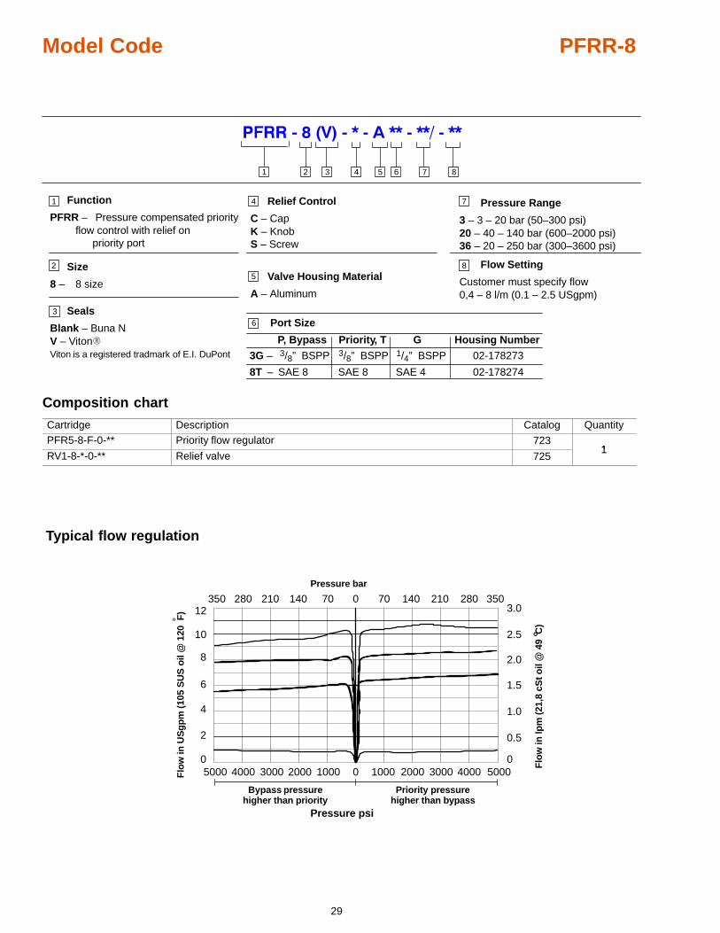
Model Code PFRR-8
Size
8 – 8 size5
3 4 5 61 2
1
2
3
4
6 Port Size
P, Bypass Housing Number
3G –
8T – SAE 8
02-178273
Pressure Range
3 – 3 – 20 bar (50–300 psi)20 – 40 – 140 bar (600–2000 psi)36 – 20 – 250 bar (300–3600 psi)
02-178274
Relief Control
C – CapK – KnobS – Screw
Function
PFRR – Pressure compensated priority flow control with relief on
priority port
7
Valve Housing Material
A – Aluminum
7
Seals
Blank – Buna NV – Viton�Viton is a registered tradmark of E.I. DuPont
Priority, T
SAE 8
G
1/4” BSPP
SAE 4
3/8” BSPP 3/8” BSPP
8
Flow Setting
Customer must specify flow0,4 – 8 l/m (0.1 – 2.5 USgpm)
8
Composition chart
Cartridge Description Catalog QuantityPFR5-8-F-0-** Priority flow regulator 723
1RV1-8-*-0-** Relief valve 725
1
4000
Typical flow regulation
10
8
6
4
2
5000
350
4000
280
3000
210
2000
140
1000
70
0 5000300020001000
0 70 140 210 280 350
0
Bypass pressurehigher than priority
Priority pressurehigher than bypass
Flo
w in
lpm
(21,
8 cS
t oil
@ 4
9 C
)o
Pressure bar
Pressure psi
3.0
2.5
2.0
1.5
1.0
0.5
0
Flo
w in
US
gp
m (1
05 S
US
oil
@ 1
20 F
)
°12
30
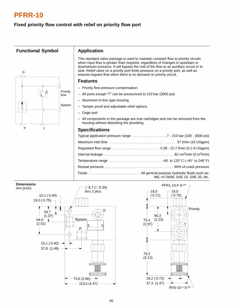
PFRR-10Fixed priority flow control with relief on priority flow port
Application
This standard valve package is used to maintain constant flow to priority circuitswhen input flow is greater than required, regardless of changes in upstream ordownstream pressure. It will bypass the rest of the flow to an auxiliary circuit or totank. Relief valve on a priority port limits pressure on a priority port, as well asensures bypass flow when there is no demand on priority circuit.
Features– Priority flow pressure compensation
– All ports except “T” can be pressurized to 210 bar (3000 psi)
– Aluminum in-line type housing
– Tamper proof and adjustable relief options
– Gage port
– All components in the package are true cartridges and can be removed from the housing without disturbing the plumbing.
SpecificationsTypical application pressure range 7 - 210 bar (100 - 3000 psi). . . . . . . . . . . . . . . . . . .
Maximum inlet flow 57 l/min (15 USgpm). . . . . . . . . . . . . . . . . . . . . . . . . . . . . . . . . . . . .
Regulated flow range 0,38 - 22,7 l/min (0.1-6 USgpm). . . . . . . . . . . . . . . . . . . . . . . . . .
Internal leakage 82 cm3/min (5 in3/min). . . . . . . . . . . . . . . . . . . . . . . . . . . . . . . . . . . . . . .
Temperature range –40 to 120�C (–40� to 248�F). . . . . . . . . . . . . . . . . . . . . . . . . . . . .
Reseat pressure 90% of crack pressure. . . . . . . . . . . . . . . . . . . . . . . . . . . . . . . . . . . . . . .
Fluids All general purpose hydraulic fluids such as:. . . . . . . . . . . . . . . . . . . . . . . . . . . . . MIL–H–5606, SAE 10, SAE 20, etc.
Dimensions mm (inch)
Functional Symbol
Bypass
Priorityflow
G
P T
G
Bypass
P
Priority
T64,0(2.52)
34,7(1.37)
19,0 ( 0.75)10,1 ( 0.40)
10,1 ( 0.40)
37,8 (1.49)
73,6 (2.90)113,5 (4.47)
79,2(3.12)
75,4(2.97)
18,0( 0.71)
PFR1-10-F-0-**
56,3(2.22)
19,0( 0.75)
18,2 ( 0.72)37,3 (1.47)
RV5-10-*-0-**
∅ 8,7 (∅ 0.34)thru 2 plcs.
31
Model Code PFRR-10
Size
10– 10 size5
3 4 5 61 2
1
2
3
4
6 Port Size
P, Bypass Housing Number
4G –10T – SAE 10
02-178275
Pressure Range
3 – 3 – 20 bar (50–300 psi)20 – 7 – 140 bar (100–2000 psi)35 – 17 – 240 bar (250–3500 psi)
02-178276
Relief Control
C – CapK – KnobS – Screw
Function
PFRR – Pressure compensated priority flow control with relief on
priority flow port
7
Valve Housing Material
A – Aluminum
7
Seals
Blank – Buna NV – Viton�Viton is a registered tradmark of E.I. DuPont
Priority, T
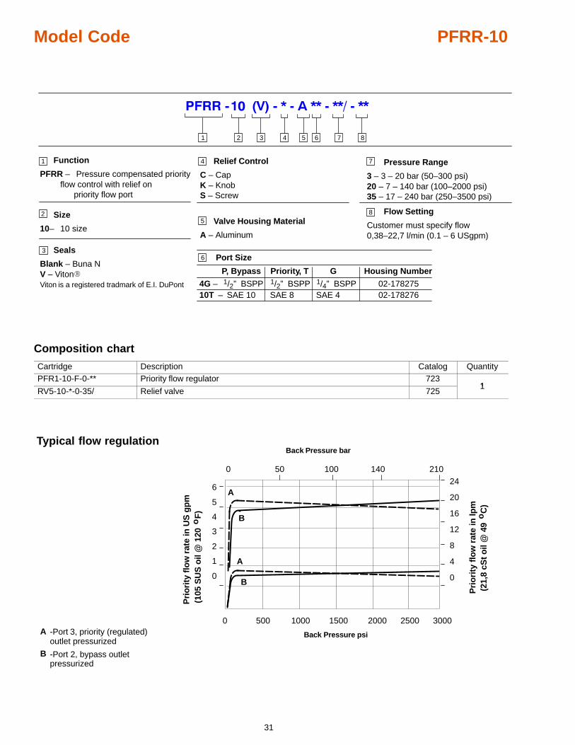
SAE 8
G
1/4” BSPP SAE 4
1/2” BSPP 1/2” BSPP
8
Flow Setting
Customer must specify flow0,38–22,7 l/min (0.1 – 6 USgpm)
8
Composition chart
Cartridge Description Catalog QuantityPFR1-10-F-0-** Priority flow regulator 723
1RV5-10-*-0-35/ Relief valve 725
1
Typical flow regulation
6
5
4
3
2
1
0
24
20
16
12
8
4
0
50 100 140 210
0 1000 2000500 1500 2500-Port 3, priority (regulated)outlet pressurized
-Port 2, bypass outletpressurized
0
Back Pressure bar
Back Pressure psi
3000A
B
A
B
A
Pri
ori
ty f
low
rat
e in
lpm
o
Pri
ori
ty f
low
rat
e in
US
gp
m(1
05 S
US
oil
@ 1
20
F)
(21,
8 cS
t o
il @
49
C
)
o
B
32
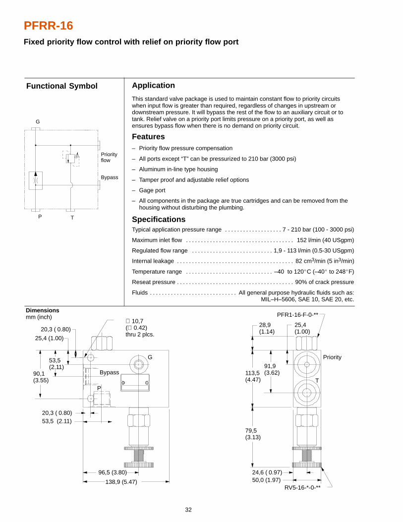
PFRR-16Fixed priority flow control with relief on priority flow port
Application
This standard valve package is used to maintain constant flow to priority circuitswhen input flow is greater than required, regardless of changes in upstream ordownstream pressure. It will bypass the rest of the flow to an auxiliary circuit or totank. Relief valve on a priority port limits pressure on a priority port, as well asensures bypass flow when there is no demand on priority circuit.
Features– Priority flow pressure compensation
– All ports except “T” can be pressurized to 210 bar (3000 psi)
– Aluminum in-line type housing
– Tamper proof and adjustable relief options
– Gage port
– All components in the package are true cartridges and can be removed from the housing without disturbing the plumbing.
SpecificationsTypical application pressure range 7 - 210 bar (100 - 3000 psi). . . . . . . . . . . . . . . . . . .
Maximum inlet flow 152 l/min (40 USgpm). . . . . . . . . . . . . . . . . . . . . . . . . . . . . . . . . . . .
Regulated flow range 1,9 - 113 l/min (0.5-30 USgpm). . . . . . . . . . . . . . . . . . . . . . . . . . .
Internal leakage 82 cm3/min (5 in3/min). . . . . . . . . . . . . . . . . . . . . . . . . . . . . . . . . . . . . . .
Temperature range –40 to 120�C (–40� to 248�F). . . . . . . . . . . . . . . . . . . . . . . . . . . . .
Reseat pressure 90% of crack pressure. . . . . . . . . . . . . . . . . . . . . . . . . . . . . . . . . . . . . . .
Fluids All general purpose hydraulic fluids such as:. . . . . . . . . . . . . . . . . . . . . . . . . . . . . MIL–H–5606, SAE 10, SAE 20, etc.
Dimensions mm (inch)
Functional Symbol
G
Bypass
P
Priority
T
PFR1-16-F-0-**
RV5-16-*-0-**
90,1(3.55)
53,5(2.11)
25,4 (1.00)
20,3 ( 0.80)
20,3 ( 0.80)53,5 (2.11)
96,5 (3.80)
138,9 (5.47)
79,5(3.13)
113,5(4.47)
28,9(1.14)
91,9(3.62)
25,4(1.00)
24,6 ( 0.97)50,0 (1.97)
∅ 10,7(∅ 0.42)thru 2 plcs.
Bypass
Priorityflow
G
P T
33
Model Code PFRR-16
Size
16– 16 size
5
3 4 5 61 2
1
2
3
4
6 Port SizeP, Bypass Housing Number
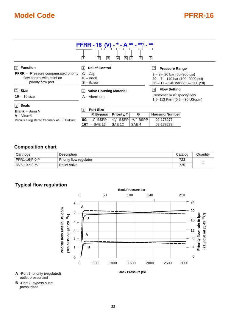
8G –16T – SAE 16
02-178277
Pressure Range
3 – 3 – 20 bar (50–300 psi)20 – 7 – 140 bar (100–2000 psi)35 – 17 – 240 bar (250–3500 psi)
02-178278
Relief Control
C – CapK – KnobS – Screw
Function
PFRR – Pressure compensated priority flow control with relief on
priority flow port
7
Valve Housing Material
A – Aluminum
7
Seals
Blank – Buna NV – Viton�Viton is a registered tradmark of E.I. DuPont
Priority, T
SAE 12
G
1/4” BSPP SAE 4
1” BSPP 3/4” BSPP
8
Flow Setting
Customer must specify flow1,9–113 l/min (0.5 – 30 USgpm)
8
Composition chart
Cartridge Description Catalog QuantityPFR1-16-F-0-** Priority flow regulator 723
1RV5-10-*-0-**/ Relief valve 725
1
50 100 140 210
0 1000 2000500 1500 2500
0
Back Pressure bar
Back Pressure psi
3000
A
B
A
Pri
ori
ty f
low
rat
e in
lpm
o
Pri
ori
ty f
low
rat
e in
US
gp
m
(105
SU
S o
il @
120
F
)
(21,
8 cS
t o
il @
49
C
)
o
B
-Port 3, priority (regulated)outlet pressurized
-Port 2, bypass outletpressurized
A
B
Typical flow regulation
0
1
2
3
4
5
6
0
4
8
12
16
20
24
34
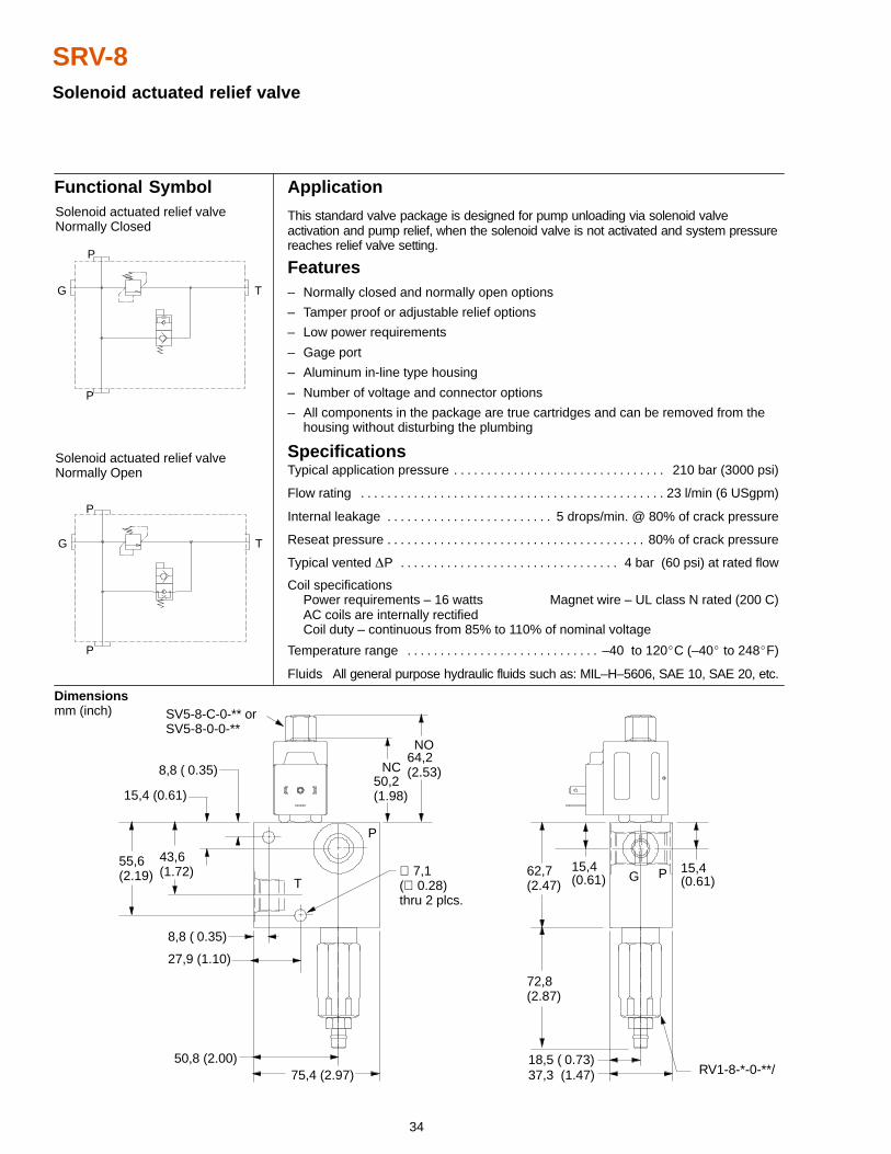
SRV-8Solenoid actuated relief valve
Application
This standard valve package is designed for pump unloading via solenoid valveactivation and pump relief, when the solenoid valve is not activated and system pressurereaches relief valve setting.
Features– Normally closed and normally open options
– Tamper proof or adjustable relief options
– Low power requirements
– Gage port
– Aluminum in-line type housing
– Number of voltage and connector options
– All components in the package are true cartridges and can be removed from the housing without disturbing the plumbing
SpecificationsTypical application pressure 210 bar (3000 psi). . . . . . . . . . . . . . . . . . . . . . . . . . . . . . . .
Flow rating 23 l/min (6 USgpm). . . . . . . . . . . . . . . . . . . . . . . . . . . . . . . . . . . . . . . . . . . . . .
Internal leakage 5 drops/min. @ 80% of crack pressure. . . . . . . . . . . . . . . . . . . . . . . . .
Reseat pressure 80% of crack pressure. . . . . . . . . . . . . . . . . . . . . . . . . . . . . . . . . . . . . . .
Typical vented �P 4 bar (60 psi) at rated flow. . . . . . . . . . . . . . . . . . . . . . . . . . . . . . . . .
Coil specificationsPower requirements – 16 watts Magnet wire – UL class N rated (200 C)AC coils are internally rectifiedCoil duty – continuous from 85% to 110% of nominal voltage
Temperature range –40 to 120�C (–40� to 248�F). . . . . . . . . . . . . . . . . . . . . . . . . . . . .
Fluids All general purpose hydraulic fluids such as: MIL–H–5606, SAE 10, SAE 20, etc.
Dimensions mm (inch)
Functional Symbol
15,4(0.61)
15,4 (0.61)
SV5-8-C-0-** orSV5-8-0-0-**
NC
NO
55,6(2.19)
43,6(1.72)
8,8 ( 0.35)50,2(1.98)
64,2(2.53)
P
T
8,8 ( 0.35)
27,9 (1.10)
PG
50,8 (2.00)75,4 (2.97)
72,8(2.87)
62,7(2.47)
15,4(0.61)
18,5 ( 0.73)RV1-8-*-0-**/37,3 (1.47)
Solenoid actuated relief valveNormally Closed
Solenoid actuated relief valveNormally Open
∅ 7,1(∅ 0.28)thru 2 plcs.
P
TG
P
P
TG
P
35
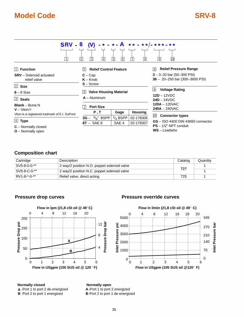
Model Code SRV-8
Function
SRV – Solenoid actuatedrelief valve
Size
8 – 8 Size
Seals
Blank – Buna NV – Viton�Viton is a registered tradmark of E.I. DuPont
Type
C – Normally closedO – Normally open
5
3 4 5 8761 2 9
1
2
3
4
7
9 Voltage Rating
12D – 12VDC24D – 24VDC120A – 120VAC240A – 240VAC
Connector types
GS – ISO 4400 DIN 43650 connectorPS – 1/2” NPT conduitWS – Leadwire
Relief Control Feature
C – CapK – KnobS – Screw
8
P , T Gage
3G – 3/8” BSPP8T – SAE 8
1/4 BSPPSAE 4
Relief Pressure Range
3 – 3–20 bar (50–300 PSI)36 – 20–250 bar (300–3600 PSI)
Housing
02-17830602-178307
Port Size
6 Valve Housing Material
A – Aluminum
10
10
Composition chart
Cartridge Description Catalog QuantitySV5-8-0-0-** 2 way/2 position N.O. poppet solenoid valve
7271
SV5-8-C-0-** 2 way/2 position N.C. poppet solenoid valve727
1
RV1-8-*-0-** Relief valve, direct acting 725 1
5000
0
Pressure drop curves
Flow in lpm (21,8 cSt oil @ 49�C)
50
100
150
200
1 2 3 4 5 6
0
Flow in USgpm (105 SUS oil @ 120 �F)
4
8
12
4 8 12 16 20
0
Pre
ssu
re D
rop
psi
Pre
ssu
re D
rop
bar
A
B
0
-Port 1 to port 2 de-energized-Port 2 to port 1 energized
AB
-Port 1 to port 2 energized-Port 2 to port 1 de-energized
AB
Normally openNormally closed
Pressure override curves
1000
2000
3000
4000
1 2 3 40
70
140
210
270
3450 4 8 12 16
Flow in l/min (21,8 cSt oil @ 49� C)
Flow in USgpm (105 SUS oil @120� F)
5 6
18 20In
let
Pre
ssu
re b
ar
Inle
t P
ress
ure
psi
0
36
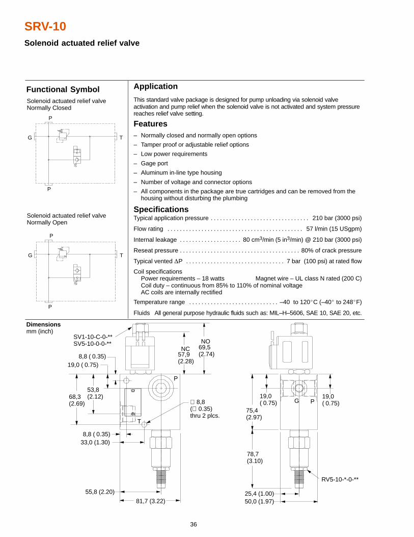
SRV-10Solenoid actuated relief valve
8,8 ( 0.35)
81,7 (3.22)
Application
This standard valve package is designed for pump unloading via solenoid valveactivation and pump relief when the solenoid valve is not activated and system pressurereaches relief valve setting.
Features– Normally closed and normally open options
– Tamper proof or adjustable relief options
– Low power requirements
– Gage port
– Aluminum in-line type housing
– Number of voltage and connector options
– All components in the package are true cartridges and can be removed from the housing without disturbing the plumbing
SpecificationsTypical application pressure 210 bar (3000 psi). . . . . . . . . . . . . . . . . . . . . . . . . . . . . . . .
Flow rating 57 l/min (15 USgpm). . . . . . . . . . . . . . . . . . . . . . . . . . . . . . . . . . . . . . . . . . . .
Internal leakage 80 cm3/min (5 in3/min) @ 210 bar (3000 psi). . . . . . . . . . . . . . . . . . . .
Reseat pressure 80% of crack pressure. . . . . . . . . . . . . . . . . . . . . . . . . . . . . . . . . . . . . . .
Typical vented �P 7 bar (100 psi) at rated flow. . . . . . . . . . . . . . . . . . . . . . . . . . . . . . . .
Coil specificationsPower requirements – 18 watts Magnet wire – UL class N rated (200 C)Coil duty – continuous from 85% to 110% of nominal voltageAC coils are internally rectified
Temperature range –40 to 120�C (–40� to 248�F). . . . . . . . . . . . . . . . . . . . . . . . . . . . .
Fluids All general purpose hydraulic fluids such as: MIL–H–5606, SAE 10, SAE 20, etc.
Dimensions mm (inch)
Functional SymbolSolenoid actuated relief valveNormally Closed
Solenoid actuated relief valveNormally Open
P
TG
P
P
TG
P
68,3(2.69)
53,8(2.12)
19,0 ( 0.75)
8,8 ( 0.35)33,0 (1.30)
55,8 (2.20)
57,9(2.28)
NC 69,5(2.74)
NO
75,4(2.97)
78,7(3.10)
19,0( 0.75)
19,0( 0.75)PG
P
T
SV1-10-C-0-**SV5-10-0-0-**
25,4 (1.00)
RV5-10-*-0-**
50,0 (1.97)
∅ 8,8(∅ 0.35)thru 2 plcs.
37
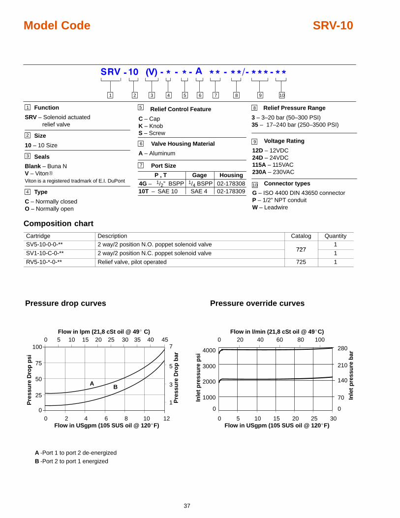
Model Code SRV-10
Function
SRV – Solenoid actuatedrelief valve
Size
10 – 10 Size
Seals
Blank – Buna NV – Viton�Viton is a registered tradmark of E.I. DuPont
Type
C – Normally closedO – Normally open
51
2
3
4
6
7
9 Voltage Rating
12D – 12VDC24D – 24VDC115A – 115VAC230A – 230VAC
Connector types
G – ISO 4400 DIN 43650 connectorP – 1/2” NPT conduitW – Leadwire
Relief Control Feature
C – CapK – KnobS – Screw
8
P , T Gage4G – 1/2” BSPP10T – SAE 10
1/4 BSPPSAE 4
Relief Pressure Range
3 – 3–20 bar (50–300 PSI)35 – 17–240 bar (250–3500 PSI)
Housing02-17830802-178309
Port Size
Valve Housing Material
A – Aluminum
10
3 4 5 8761 2 9 10
Composition chart
Cartridge Description Catalog QuantitySV5-10-0-0-** 2 way/2 position N.O. poppet solenoid valve
7271
SV1-10-C-0-** 2 way/2 position N.C. poppet solenoid valve727
1
RV5-10-*-0-** Relief valve, pilot operated 725 1
Pressure drop curves
0100
0
25
50
75
30252015105 35 40 45
2 4 6 8 10 12
Flow in lpm (21,8 cSt oil @ 49� C)
Flow in USgpm (105 SUS oil @ 120�F)
1
3
5
7
Pre
ssu
re D
rop
psi
Pre
ssu
re D
rop
bar
A B
0
-Port 1 to port 2 de-energized-Port 2 to port 1 energized
AB
Pressure override curves
Flow in l/min (21,8 cSt oil @ 49�C)
Inle
t p
ress
ure
psi
Inle
t p
ress
ure
bar
Flow in USgpm (105 SUS oil @ 120�F)0 5 10 15 20 25 30
70
280
2000
3000
4000
0 20 40 60 80 100
0 0
140
1000
210
38
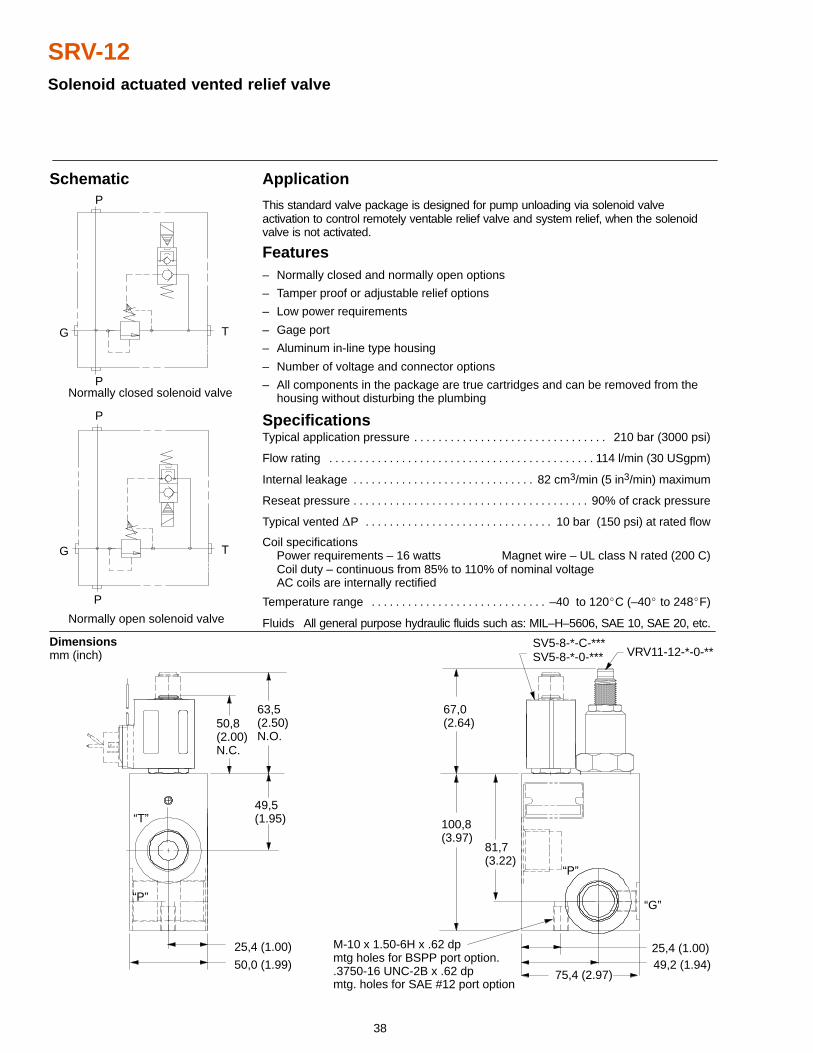
SRV-12Solenoid actuated vented relief valve
M-10 x 1.50-6H x .62 dpmtg holes for BSPP port option..3750-16 UNC-2B x .62 dpmtg. holes for SAE #12 port option
Application
This standard valve package is designed for pump unloading via solenoid valveactivation to control remotely ventable relief valve and system relief, when the solenoidvalve is not activated.
Features– Normally closed and normally open options
– Tamper proof or adjustable relief options
– Low power requirements
– Gage port
– Aluminum in-line type housing
– Number of voltage and connector options
– All components in the package are true cartridges and can be removed from the housing without disturbing the plumbing
SpecificationsTypical application pressure 210 bar (3000 psi). . . . . . . . . . . . . . . . . . . . . . . . . . . . . . . .
Flow rating 114 l/min (30 USgpm). . . . . . . . . . . . . . . . . . . . . . . . . . . . . . . . . . . . . . . . . . . .
Internal leakage 82 cm3/min (5 in3/min) maximum. . . . . . . . . . . . . . . . . . . . . . . . . . . . . .
Reseat pressure 90% of crack pressure. . . . . . . . . . . . . . . . . . . . . . . . . . . . . . . . . . . . . . .
Typical vented �P 10 bar (150 psi) at rated flow. . . . . . . . . . . . . . . . . . . . . . . . . . . . . . .
Coil specificationsPower requirements – 16 watts Magnet wire – UL class N rated (200 C)Coil duty – continuous from 85% to 110% of nominal voltageAC coils are internally rectified
Temperature range –40 to 120�C (–40� to 248�F). . . . . . . . . . . . . . . . . . . . . . . . . . . . .
Fluids All general purpose hydraulic fluids such as: MIL–H–5606, SAE 10, SAE 20, etc.
Dimensions mm (inch)
Schematic
49,5(1.95)
50,8(2.00)N.C.
63,5(2.50)N.O.
67,0(2.64)
100,8(3.97)
81,7(3.22)
25,4 (1.00)
50,0 (1.99)
SV5-8-*-0-*** VRV11-12-*-0-**
25,4 (1.00)49,2 (1.94)
75,4 (2.97)
Normally closed solenoid valve
Normally open solenoid valve
G T
P
P
P
P
G T
“P”
“G”
“T”
“P”
SV5-8-*-C-***
39
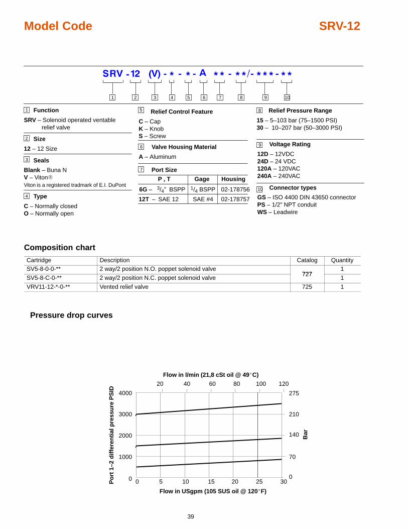
Model Code SRV-12
Function
SRV – Solenoid operated ventablerelief valve
Size
12 – 12 Size
Seals
Blank – Buna NV – Viton�Viton is a registered tradmark of E.I. DuPont
Type
C – Normally closedO – Normally open
51
2
3
4
6
7
9 Voltage Rating
12D – 12VDC24D – 24 VDC120A – 120VAC240A – 240VAC
Connector types
GS – ISO 4400 DIN 43650 connectorPS – 1/2” NPT conduitWS – Leadwire
Relief Control Feature
C – CapK – KnobS – Screw
8
P , T Gage
6G – 3/4” BSPP
12T – SAE 12
1/4 BSPP
SAE #4
Relief Pressure Range
15 – 5–103 bar (75–1500 PSI)30 – 10–207 bar (50–3000 PSI)
Housing
Port Size
Valve Housing Material
A – Aluminum
10
3 4 5 8761 2 9 10
02-178756
02-178757
Composition chart
Cartridge Description Catalog QuantitySV5-8-0-0-** 2 way/2 position N.O. poppet solenoid valve
7271
SV5-8-C-0-** 2 way/2 position N.C. poppet solenoid valve727
1
VRV11-12-*-0-** Vented relief valve 725 1
Pressure drop curves
0
1000
2000
3000
4000
20 40 60 80 100 120
0 5 10 15 20 25 30
70
140
210
Bar
Po
rt 1
–2 d
iffe
ren
tial
pre
ssu
re P
SID 275
0
Flow in l/min (21,8 cSt oil @ 49�C)
Flow in USgpm (105 SUS oil @ 120�F)
40
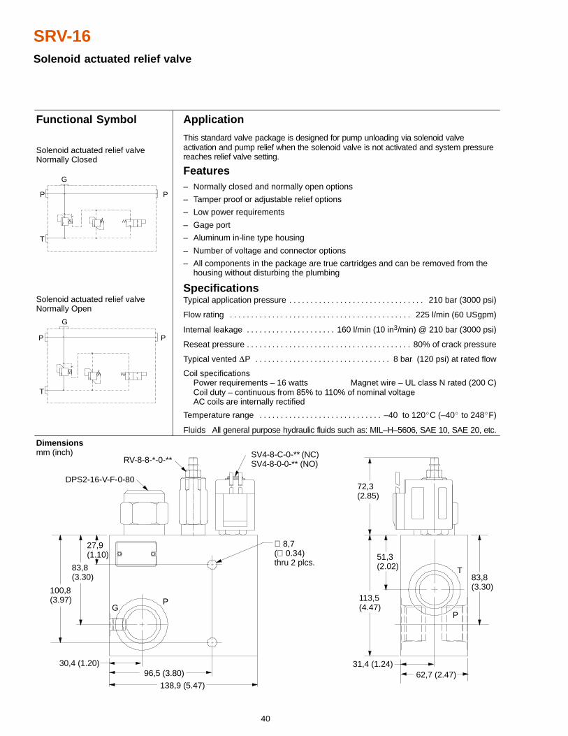
SRV-16Solenoid actuated relief valve
Application
This standard valve package is designed for pump unloading via solenoid valveactivation and pump relief when the solenoid valve is not activated and system pressurereaches relief valve setting.
Features– Normally closed and normally open options
– Tamper proof or adjustable relief options
– Low power requirements
– Gage port
– Aluminum in-line type housing
– Number of voltage and connector options
– All components in the package are true cartridges and can be removed from the housing without disturbing the plumbing
SpecificationsTypical application pressure 210 bar (3000 psi). . . . . . . . . . . . . . . . . . . . . . . . . . . . . . . .
Flow rating 225 l/min (60 USgpm). . . . . . . . . . . . . . . . . . . . . . . . . . . . . . . . . . . . . . . . . . .
Internal leakage 160 l/min (10 in3/min) @ 210 bar (3000 psi). . . . . . . . . . . . . . . . . . . . .
Reseat pressure 80% of crack pressure. . . . . . . . . . . . . . . . . . . . . . . . . . . . . . . . . . . . . . .
Typical vented �P 8 bar (120 psi) at rated flow. . . . . . . . . . . . . . . . . . . . . . . . . . . . . . . .
Coil specificationsPower requirements – 16 watts Magnet wire – UL class N rated (200 C)Coil duty – continuous from 85% to 110% of nominal voltageAC coils are internally rectified
Temperature range –40 to 120�C (–40� to 248�F). . . . . . . . . . . . . . . . . . . . . . . . . . . . .
Fluids All general purpose hydraulic fluids such as: MIL–H–5606, SAE 10, SAE 20, etc.
Dimensions mm (inch)
Functional Symbol
DPS2-16-V-F-0-80
RV-8-8-*-0-**SV4-8-C-0-** (NC)SV4-8-0-0-** (NO)
PG
T
P
100,8(3.97)
83,8(3.30)
27,9(1.10)
30,4 (1.20)96,5 (3.80)
138,9 (5.47)62,7 (2.47)
31,4 (1.24)
72,3(2.85)
113,5(4.47)
51,3(2.02)
83,8(3.30)
T
P
G
P
P P
G
T
Solenoid actuated relief valveNormally Closed
Solenoid actuated relief valveNormally Open
∅ 8,7(∅ 0.34)thru 2 plcs.
41
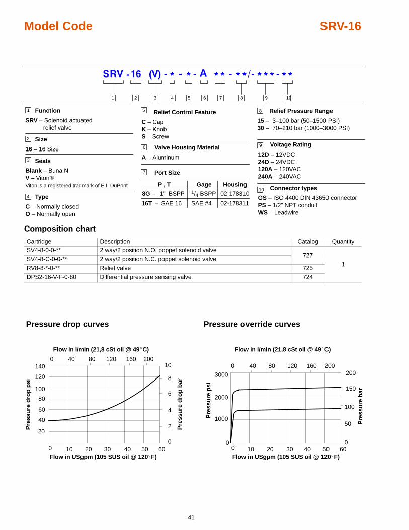
Model Code SRV-16
Function
SRV – Solenoid actuatedrelief valve
Size
16 – 16 Size
Seals
Blank – Buna NV – Viton�Viton is a registered tradmark of E.I. DuPont
Type
C – Normally closedO – Normally open
51
2
3
4
6
7
9 Voltage Rating
12D – 12VDC24D – 24VDC120A – 120VAC240A – 240VAC
Connector types
GS – ISO 4400 DIN 43650 connectorPS – 1/2” NPT conduitWS – Leadwire
Relief Control Feature
C – CapK – KnobS – Screw
8
P , T Gage
8G – 1” BSPP
16T – SAE 16
1/4 BSPP
SAE #4
Relief Pressure Range
15 – 3–100 bar (50–1500 PSI)30 – 70–210 bar (1000–3000 PSI)
Housing
02-178310
02-178311
Port Size
Valve Housing Material
A – Aluminum
10
3 4 5 8761 2 9 10
Composition chart
Cartridge Description Catalog QuantitySV4-8-0-0-** 2 way/2 position N.O. poppet solenoid valve
727SV4-8-C-0-0-** 2 way/2 position N.C. poppet solenoid valve
727
1RV8-8-*-0-** Relief valve 725
1
DPS2-16-V-F-0-80 Differential pressure sensing valve 724
Flow in l/min (21,8 cSt oil @ 49�C)
Flow in USgpm (105 SUS oil @ 120�F)
Pressure drop curves
0
1000
2000
0
50
100
150
200
0 10 20 30 40 50
40 80 1200 160
3000
60
200P
ress
ure
bar
Pre
ssu
re p
si
0
240
60
80
140
0 10 20 30 40 50
40 80 1200 160
60
200
Pre
ssu
re d
rop
bar
Pre
ssu
re d
rop
psi
4
6
8
10
20
100
120
Pressure override curves
Flow in l/min (21,8 cSt oil @ 49�C)
Flow in USgpm (105 SUS oil @ 120�F)
42
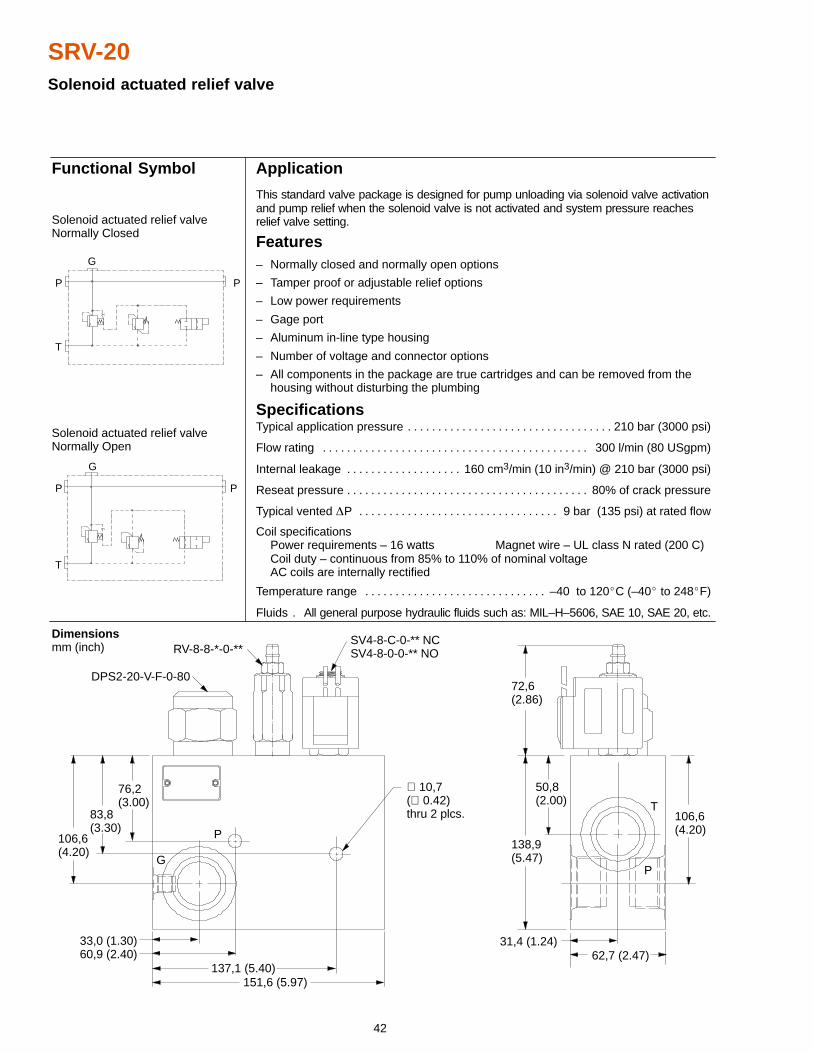
SRV-20Solenoid actuated relief valve
Application
This standard valve package is designed for pump unloading via solenoid valve activationand pump relief when the solenoid valve is not activated and system pressure reachesrelief valve setting.
Features– Normally closed and normally open options
– Tamper proof or adjustable relief options
– Low power requirements
– Gage port
– Aluminum in-line type housing
– Number of voltage and connector options
– All components in the package are true cartridges and can be removed from the housing without disturbing the plumbing
SpecificationsTypical application pressure 210 bar (3000 psi). . . . . . . . . . . . . . . . . . . . . . . . . . . . . . . . . .
Flow rating 300 l/min (80 USgpm). . . . . . . . . . . . . . . . . . . . . . . . . . . . . . . . . . . . . . . . . . . .
Internal leakage 160 cm3/min (10 in3/min) @ 210 bar (3000 psi). . . . . . . . . . . . . . . . . . .
Reseat pressure 80% of crack pressure. . . . . . . . . . . . . . . . . . . . . . . . . . . . . . . . . . . . . . . .
Typical vented �P 9 bar (135 psi) at rated flow. . . . . . . . . . . . . . . . . . . . . . . . . . . . . . . . .
Coil specificationsPower requirements – 16 watts Magnet wire – UL class N rated (200 C)Coil duty – continuous from 85% to 110% of nominal voltageAC coils are internally rectified
Temperature range –40 to 120�C (–40� to 248�F). . . . . . . . . . . . . . . . . . . . . . . . . . . . . .
Fluids All general purpose hydraulic fluids such as: MIL–H–5606, SAE 10, SAE 20, etc..
Functional Symbol
T
P
G
P
P P
G
T
Solenoid actuated relief valveNormally Closed
Solenoid actuated relief valveNormally Open
DPS2-20-V-F-0-80
RV-8-8-*-0-**SV4-8-C-0-** NCSV4-8-0-0-** NO
P
G
T
P
Dimensions mm (inch)
106,6(4.20)
83,8(3.30)
76,2(3.00)
33,0 (1.30)60,9 (2.40)
137,1 (5.40)151,6 (5.97)
72,6(2.86)
138,9(5.47)
50,8(2.00)
106,6(4.20)
31,4 (1.24)62,7 (2.47)
∅ 10,7(∅ 0.42)thru 2 plcs.
43
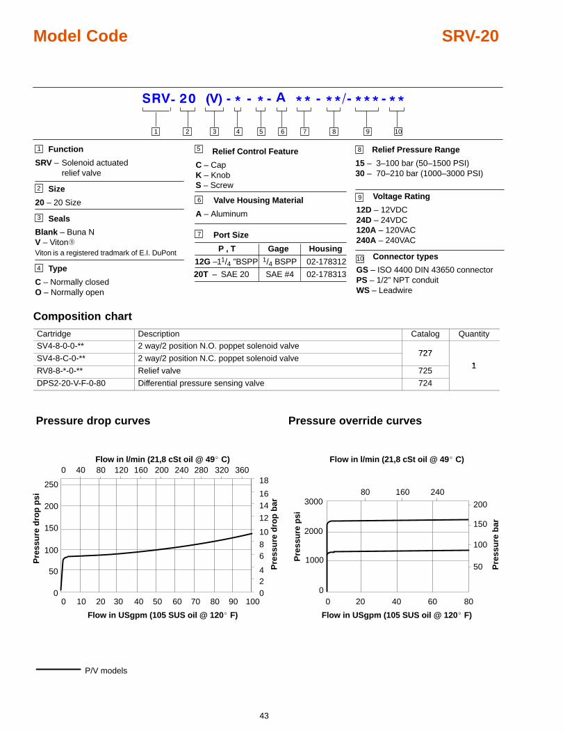
Model Code SRV-20
11/4 ”BSPP
Function
SRV – Solenoid actuatedrelief valve
Size
20 – 20 Size
Seals
Blank – Buna NV – Viton�Viton is a registered tradmark of E.I. DuPont
Type
C – Normally closedO – Normally open
51
2
3
4
6
7
9 Voltage Rating
12D – 12VDC24D – 24VDC120A – 120VAC240A – 240VAC
Connector types
GS – ISO 4400 DIN 43650 connectorPS – 1/2” NPT conduitWS – Leadwire
Relief Control Feature
C – CapK – KnobS – Screw
8
P , T Gage
12G –
20T – SAE 20
1/4 BSPP
SAE #4
Relief Pressure Range
15 – 3–100 bar (50–1500 PSI)30 – 70–210 bar (1000–3000 PSI)
Housing
02-178312
02-178313
Port Size
Valve Housing Material
A – Aluminum
10
3 4 5 8761 2 9 10
Composition chart
Cartridge Description Catalog QuantitySV4-8-0-0-** 2 way/2 position N.O. poppet solenoid valve
727SV4-8-C-0-** 2 way/2 position N.C. poppet solenoid valve
727
1RV8-8-*-0-** Relief valve 725
1
DPS2-20-V-F-0-80 Differential pressure sensing valve 724
024
68
10
12
1416
18
0
50
100
150
200
250
0 40 80 120 160 200 240 280 320 360Flow in l/min (21,8 cSt oil @ 49� C)
Flow in USgpm (105 SUS oil @ 120� F)
Pre
ssu
re d
rop
psi
Pre
ssu
re d
rop
bar
0 10 20 30 40 50 60 70 80 90 100
P/V models
Pressure drop curves Pressure override curves
20 40 60 800
200
150
100
50
3000
2000
1000
0
Pre
ssu
re b
ar
Pre
ssu
re p
si
80 160 240
Flow in l/min (21,8 cSt oil @ 49� C)
Flow in USgpm (105 SUS oil @ 120� F)
44
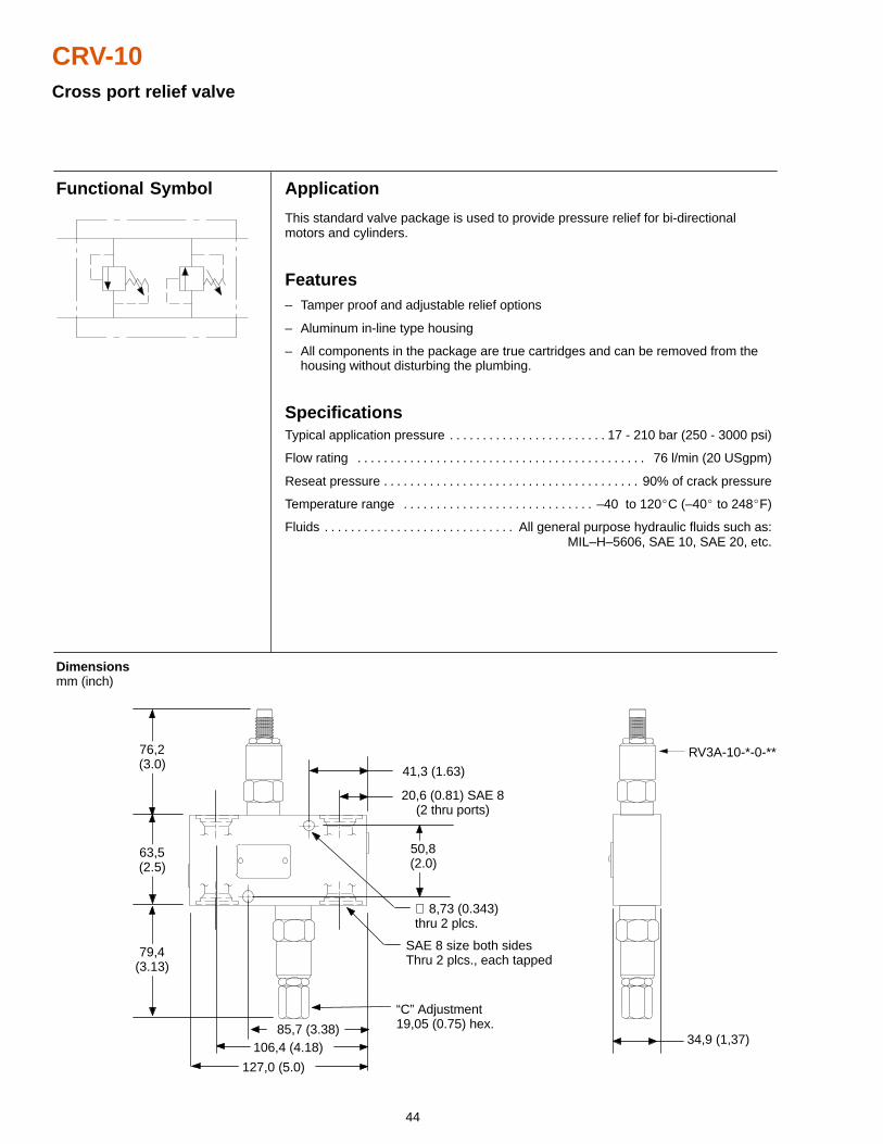
CRV-10Cross port relief valve
85,7 (3.38)
Application
This standard valve package is used to provide pressure relief for bi-directionalmotors and cylinders.
Features– Tamper proof and adjustable relief options
– Aluminum in-line type housing
– All components in the package are true cartridges and can be removed from the housing without disturbing the plumbing.
SpecificationsTypical application pressure 17 - 210 bar (250 - 3000 psi). . . . . . . . . . . . . . . . . . . . . . . .
Flow rating 76 l/min (20 USgpm). . . . . . . . . . . . . . . . . . . . . . . . . . . . . . . . . . . . . . . . . . . .
Reseat pressure 90% of crack pressure. . . . . . . . . . . . . . . . . . . . . . . . . . . . . . . . . . . . . . .
Temperature range –40 to 120�C (–40� to 248�F). . . . . . . . . . . . . . . . . . . . . . . . . . . . .
Fluids All general purpose hydraulic fluids such as:. . . . . . . . . . . . . . . . . . . . . . . . . . . . . MIL–H–5606, SAE 10, SAE 20, etc.
Dimensions mm (inch)
Functional Symbol
127,0 (5.0)
76,2(3.0)
63,5(2.5)
79,4(3.13)
50,8(2.0)
“C” Adjustment19,05 (0.75) hex.
∅ 8,73 (0.343)thru 2 plcs.
41,3 (1.63)
34,9 (1,37)
RV3A-10-*-0-**
20,6 (0.81) SAE 8(2 thru ports)
106,4 (4.18)
SAE 8 size both sidesThru 2 plcs., each tapped
45
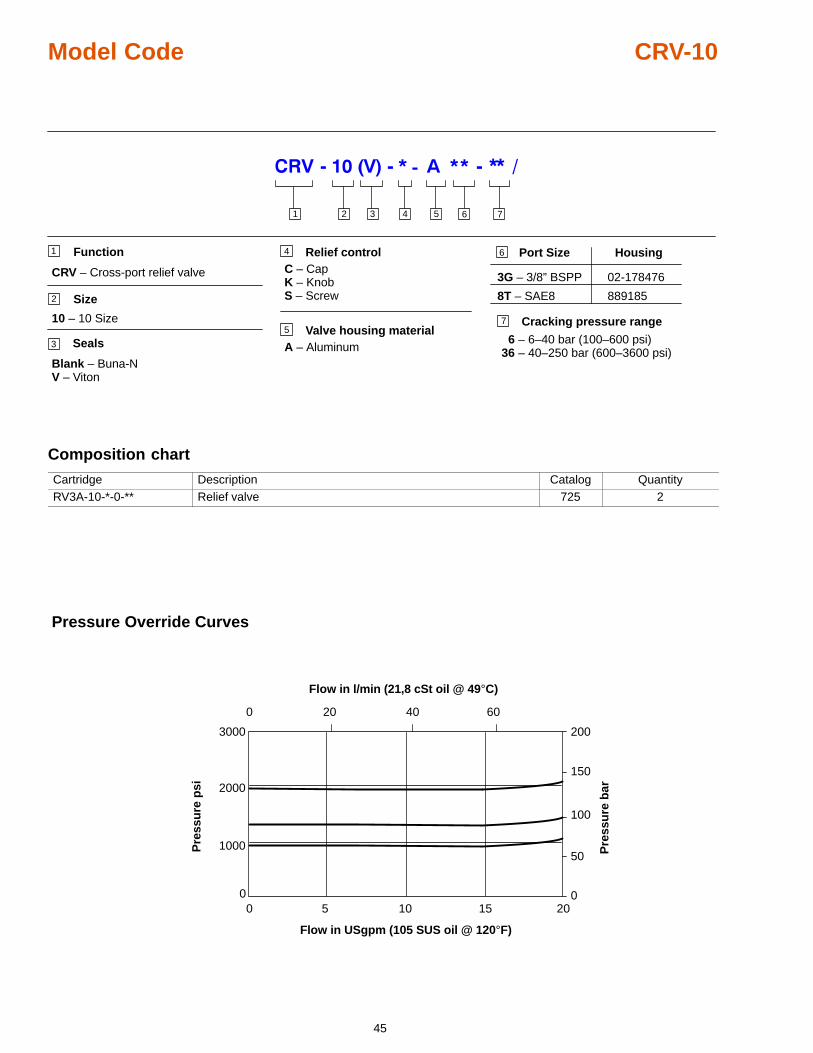
Model Code CRV-10
7
2 3 4 51
CRV – Cross-port relief valve
Function
Size
10 – 10 Size
Seals
Blank – Buna-NV – Viton
Valve housing materialA – Aluminum
Port Size Housing
3G – 3/8” BSPP 02-178476
8T – SAE8 889185
6
1
2
3
5Cracking pressure range
6 – 6–40 bar (100–600 psi)36 – 40–250 bar (600–3600 psi)
6
7
Relief controlC – CapK – KnobS – Screw
4
Composition chart
Cartridge Description Catalog QuantityRV3A-10-*-0-** Relief valve 725 2
Pressure Override Curves
20 40 60
0 5 10 15 20
Flow in l/min (21,8 cSt oil @ 49°C)
Flow in USgpm (105 SUS oil @ 120°F)
Pre
ssu
re p
si
Pre
ssu
re b
ar
0
0
50
100
150
200
0
1000
2000
3000
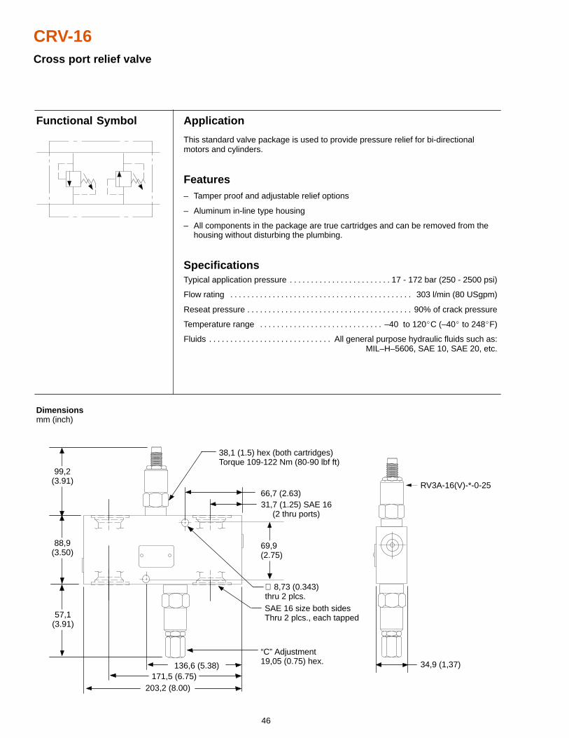
46
CRV-16Cross port relief valve
38,1 (1.5) hex (both cartridges)Torque 109-122 Nm (80-90 lbf ft)
Application
This standard valve package is used to provide pressure relief for bi-directionalmotors and cylinders.
Features– Tamper proof and adjustable relief options
– Aluminum in-line type housing
– All components in the package are true cartridges and can be removed from the housing without disturbing the plumbing.
SpecificationsTypical application pressure 17 - 172 bar (250 - 2500 psi). . . . . . . . . . . . . . . . . . . . . . . .
Flow rating 303 l/min (80 USgpm). . . . . . . . . . . . . . . . . . . . . . . . . . . . . . . . . . . . . . . . . . .
Reseat pressure 90% of crack pressure. . . . . . . . . . . . . . . . . . . . . . . . . . . . . . . . . . . . . . .
Temperature range –40 to 120�C (–40� to 248�F). . . . . . . . . . . . . . . . . . . . . . . . . . . . .
Fluids All general purpose hydraulic fluids such as:. . . . . . . . . . . . . . . . . . . . . . . . . . . . . MIL–H–5606, SAE 10, SAE 20, etc.
Dimensions mm (inch)
Functional Symbol
SAE 16 size both sidesThru 2 plcs., each tapped
99,2(3.91)
88,9(3.50)
57,1(3.91)
“C” Adjustment19,05 (0.75) hex.
∅ 8,73 (0.343)thru 2 plcs.
34,9 (1,37)
RV3A-16(V)-*-0-25
31,7 (1.25) SAE 16(2 thru ports)
171,5 (6.75)136,6 (5.38)
203,2 (8.00)
66,7 (2.63)
69,9(2.75)
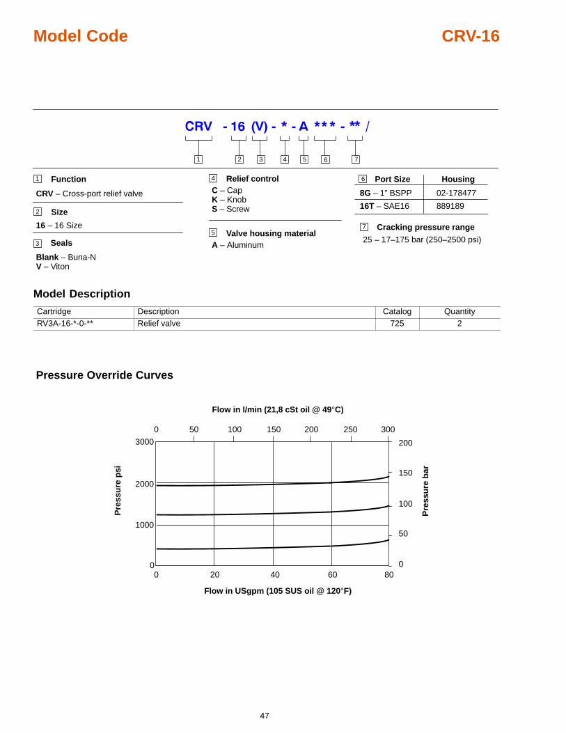
47
Model Code CRV-16
2 3 4 51
CRV – Cross-port relief valve
Function
Size
16 – 16 Size
Seals
Blank – Buna-NV – Viton
6
1
2
3
7Valve housing material
A – Aluminum
Port Size Housing
8G – 1” BSPP 02-178477
16T – SAE16 889189
5Cracking pressure range
25 – 17–175 bar (250–2500 psi)
6Relief controlC – CapK – KnobS – Screw
4
7
Model Description
Cartridge Description Catalog QuantityRV3A-16-*-0-** Relief valve 725 2
50 100 150
0 20 40 60 80
Flow in l/min (21,8 cSt oil @ 49°C)
Flow in USgpm (105 SUS oil @ 120°F)
Pre
ssu
re p
si
Pre
ssu
re b
ar0
0
50
100
150
200
0
1000
2000
3000
200 250 300
Pressure Override Curves
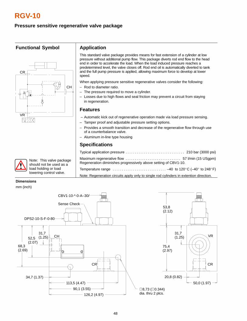
48
RGV-10Pressure sensitive regenerative valve package
ApplicationThis standard valve package provides means for fast extension of a cylinder at lowpressure without additional pump flow. This package diverts rod end flow to the headend in order to accelerate the load. When the load induced pressure reaches apredetermined level, the valve closes off. Rod end oil is automatically diverted to tankand the full pump pressure is applied, allowing maximum force to develop at lowerspeed.
When applying pressure sensitive regenerative valves consider the following:– Rod to diameter ratio.– The pressure required to move a cylinder.– Losses due to high flows and seal friction may prevent a circuit from staying
in regeneration.
Features – Automatic kick out of regenerative operation made via load pressure sensing.– Tamper proof and adjustable pressure setting options.
– Provides a smooth transition and decrease of the regenerative flow through useof a counterbalance valve.
– Aluminum in-line type housing
SpecificationsTypical application pressure 210 bar (3000 psi). . . . . . . . . . . . . . . . . . . . . . . . . . . . . . . .
Maximum regenerative flow 57 l/min (15 USgpm). . . . . . . . . . . . . . . . . . . . . . . . . . . . . . Regeneration diminishes progressively above setting of CBV1-10.
Temperature range –40 to 120�C (–40� to 248�F). . . . . . . . . . . . . . . . . . . . . . . . . . . . .
Note: Regeneration circuits apply only to single rod cylinders in extention direction.
Dimensions
mm (inch)
Functional Symbol
Note: This valve packageshould not be used as aload holding or loadlowering control valve.
CBV1-10-*-0-A–30/
Sense Check
DPS2-10-S-F-0-80
CH
CR
68,3(2.69)
52,5(2.07)
31,7(1.25)
34,7 (1.37)
113,5 (4.47)
90,1 (3.55)
126,2 (4.97)
∅ 8,73 (∅ 0.344) dia. thru 2 plcs.
75,4(2.97)
53,8(2.12)
31,7(1.25) VR
CR
50,0 (1.97)
20,8 (0.82)
VR
CH
CR
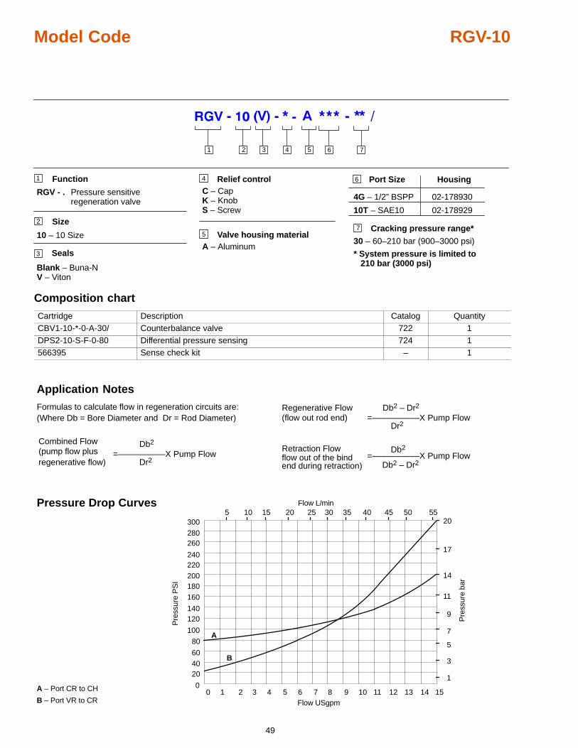
49
Model Code RGV-10
7
Function
Size
10 – 10 Size
Seals
Blank – Buna-NV – Viton
Valve housing materialA – Aluminum
Port Size Housing
4G – 1/2” BSPP 02-178930
10T – SAE10 02-178929
1
2
3
5Cracking pressure range*
30 – 60–210 bar (900–3000 psi)
6Relief controlC – CapK – KnobS – Screw
4
2 3 4 51 6 7
RGV - Pressure sensitive. regeneration valve
* System pressure is limited to 210 bar (3000 psi)
Composition chart
Cartridge Description Catalog QuantityCBV1-10-*-0-A-30/ Counterbalance valve 722 1DPS2-10-S-F-0-80 Differential pressure sensing 724 1566395 Sense check kit – 1
0 1 2 3 4 5 6 7 8 9 10 11 12 13 14 15
204060
80
100
120140
160180200220240
260280300
0
5 10 15 20 25 30 35 40 45 50 55
1
3
5
7
9
11
14
17
20
A – Port CR to CH
B – Port VR to CR
A
B
Pre
ssur
e P
SI
Pre
ssur
e ba
r
Flow USgpm
Flow L/minPressure Drop Curves
Formulas to calculate flow in regeneration circuits are:(Where Db = Bore Diameter and Dr = Rod Diameter)
Regenerative Flow Db2 – Dr2
Db2 – Dr2
(flow out rod end)
=––––––––––X Pump FlowDr2
Combined Flow(pump flow plusregenerative flow)
Retraction FlowDb2
flow out of the bindend during retraction)
=––––––––––X Pump FlowDr2
=––––––––––X Pump FlowDb2
Application Notes
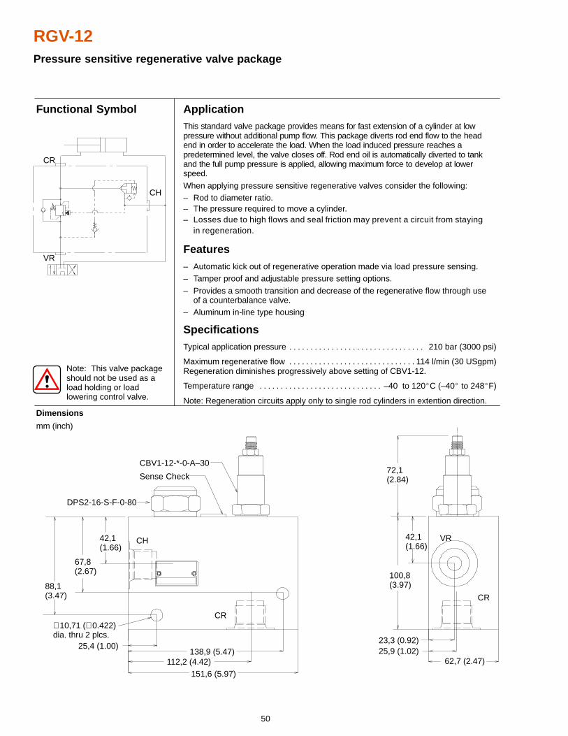
50
RGV-12Pressure sensitive regenerative valve package
62,7 (2.47)
ApplicationThis standard valve package provides means for fast extension of a cylinder at lowpressure without additional pump flow. This package diverts rod end flow to the headend in order to accelerate the load. When the load induced pressure reaches apredetermined level, the valve closes off. Rod end oil is automatically diverted to tankand the full pump pressure is applied, allowing maximum force to develop at lowerspeed.
When applying pressure sensitive regenerative valves consider the following:– Rod to diameter ratio.– The pressure required to move a cylinder.– Losses due to high flows and seal friction may prevent a circuit from staying
in regeneration.
Features– Automatic kick out of regenerative operation made via load pressure sensing.– Tamper proof and adjustable pressure setting options.
– Provides a smooth transition and decrease of the regenerative flow through useof a counterbalance valve.
– Aluminum in-line type housing
SpecificationsTypical application pressure 210 bar (3000 psi). . . . . . . . . . . . . . . . . . . . . . . . . . . . . . . .
Maximum regenerative flow 114 l/min (30 USgpm). . . . . . . . . . . . . . . . . . . . . . . . . . . . . . Regeneration diminishes progressively above setting of CBV1-12.
Temperature range –40 to 120�C (–40� to 248�F). . . . . . . . . . . . . . . . . . . . . . . . . . . . .
Note: Regeneration circuits apply only to single rod cylinders in extention direction.
Dimensions
mm (inch)
Functional Symbol
42,1(1.66)
67,8(2.67)
CBV1-12-*-0-A–30
Sense Check
DPS2-16-S-F-0-80
88,1(3.47)
CH
CR
25,4 (1.00)
151,6 (5.97)112,2 (4.42)
138,9 (5.47)
72,1(2.84)
100,8(3.97)
42,1(1.66)
VR
CR
23,3 (0.92)25,9 (1.02)
∅ 10,71 (∅ 0.422)dia. thru 2 plcs.
Note: This valve packageshould not be used as aload holding or loadlowering control valve.
VR
CH
CR
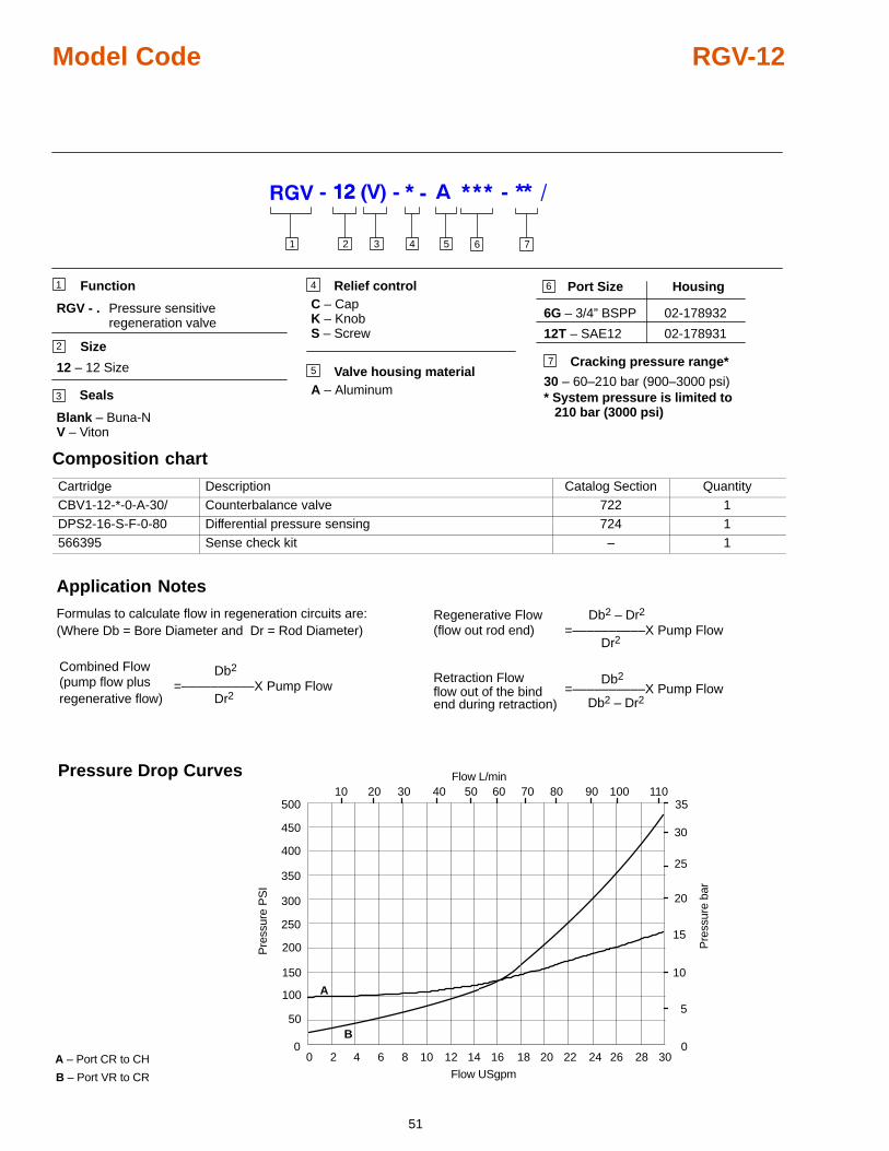
51
Model Code RGV-12
7
2 3 4 51
RGV - Pressure sensitive. regeneration valve
Function
Size
12 – 12 Size
Seals
Blank – Buna-NV – Viton
Valve housing materialA – Aluminum
Port Size Housing
6G – 3/4” BSPP 02-178932
12T – SAE12 02-178931
6
1
2
3
5Cracking pressure range*
30 – 60–210 bar (900–3000 psi)
6
7
Relief controlC – CapK – KnobS – Screw
4
* System pressure is limited to 210 bar (3000 psi)
Composition chart
Cartridge Description Catalog Section QuantityCBV1-12-*-0-A-30/ Counterbalance valve 722 1DPS2-16-S-F-0-80 Differential pressure sensing 724 1566395 Sense check kit – 1
0 2 4 6 8 10 12 14 16 18 20 22 24 26 28 30
50
100
150
200
250
300
350
400
450
500
0
10 20 30 40 50
5
20
25
30
35
A – Port CR to CH
B – Port VR to CR
A
B
Pre
ssur
e P
SI
Pre
ssur
e ba
r
Flow USgpm
Flow L/min
10
15
0
60 70 80 90 100 110
Pressure Drop Curves
Formulas to calculate flow in regeneration circuits are:(Where Db = Bore Diameter and Dr = Rod Diameter)
Regenerative Flow Db2 – Dr2
Db2 – Dr2
(flow out rod end)
=––––––––––X Pump FlowDr2
Combined Flow(pump flow plusregenerative flow)
Retraction FlowDb2
flow out of the bindend during retraction)
=––––––––––X Pump FlowDr2
=––––––––––X Pump FlowDb2
Application Notes
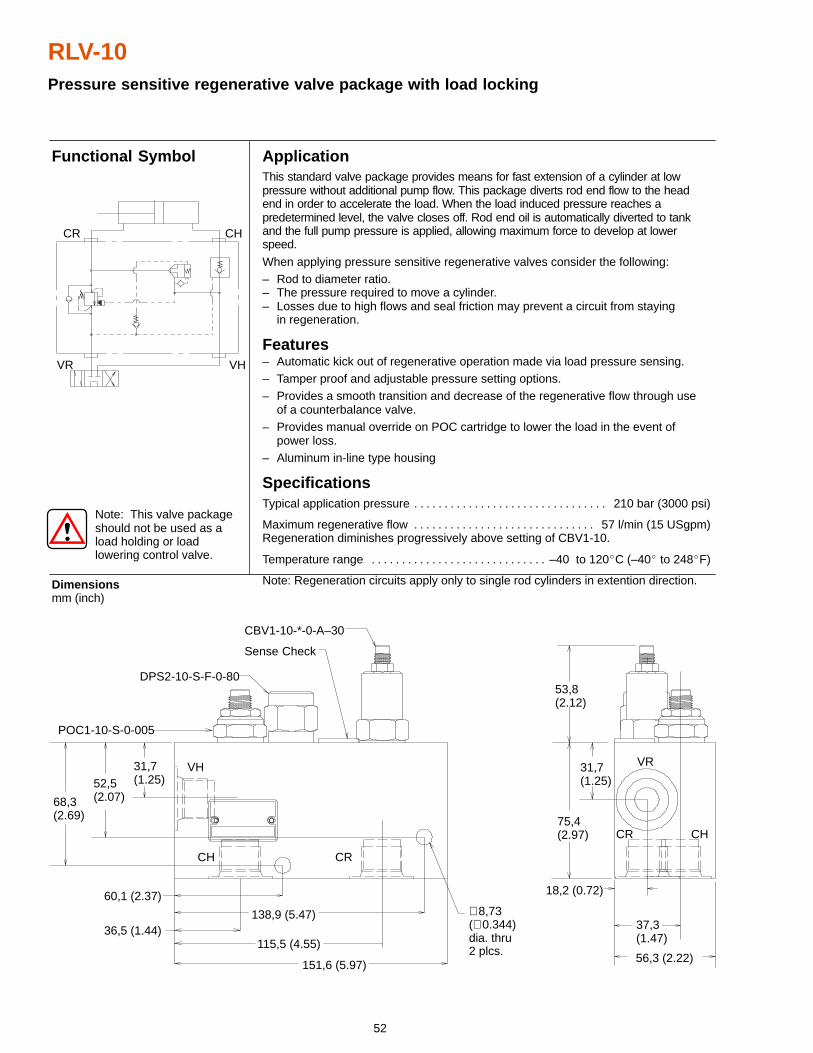
52
RLV-10Pressure sensitive regenerative valve package with load locking
31,7(1.25)
ApplicationThis standard valve package provides means for fast extension of a cylinder at lowpressure without additional pump flow. This package diverts rod end flow to the headend in order to accelerate the load. When the load induced pressure reaches apredetermined level, the valve closes off. Rod end oil is automatically diverted to tankand the full pump pressure is applied, allowing maximum force to develop at lowerspeed.
When applying pressure sensitive regenerative valves consider the following:– Rod to diameter ratio.– The pressure required to move a cylinder.– Losses due to high flows and seal friction may prevent a circuit from staying
in regeneration.
Features– Automatic kick out of regenerative operation made via load pressure sensing.– Tamper proof and adjustable pressure setting options.– Provides a smooth transition and decrease of the regenerative flow through use
of a counterbalance valve.– Provides manual override on POC cartridge to lower the load in the event of
power loss.– Aluminum in-line type housing
SpecificationsTypical application pressure 210 bar (3000 psi). . . . . . . . . . . . . . . . . . . . . . . . . . . . . . . .
Maximum regenerative flow 57 l/min (15 USgpm). . . . . . . . . . . . . . . . . . . . . . . . . . . . . . Regeneration diminishes progressively above setting of CBV1-10.
Temperature range –40 to 120�C (–40� to 248�F). . . . . . . . . . . . . . . . . . . . . . . . . . . . .
Note: Regeneration circuits apply only to single rod cylinders in extention direction.Dimensionsmm (inch)
Functional Symbol
Note: This valve packageshould not be used as aload holding or loadlowering control valve.
52,5(2.07)
DPS2-10-S-F-0-80
CBV1-10-*-0-A–30
Sense Check
POC1-10-S-0-005
68,3(2.69)
VH
CH CR
151,6 (5.97)
115,5 (4.55)36,5 (1.44)
138,9 (5.47)
60,1 (2.37)∅ 8,73(∅ 0.344) dia. thru2 plcs.
56,3 (2.22)
37,3(1.47)
18,2 (0.72)
53,8(2.12)
75,4(2.97)
31,7(1.25)
VR
CR CH
VR VH
CR CH
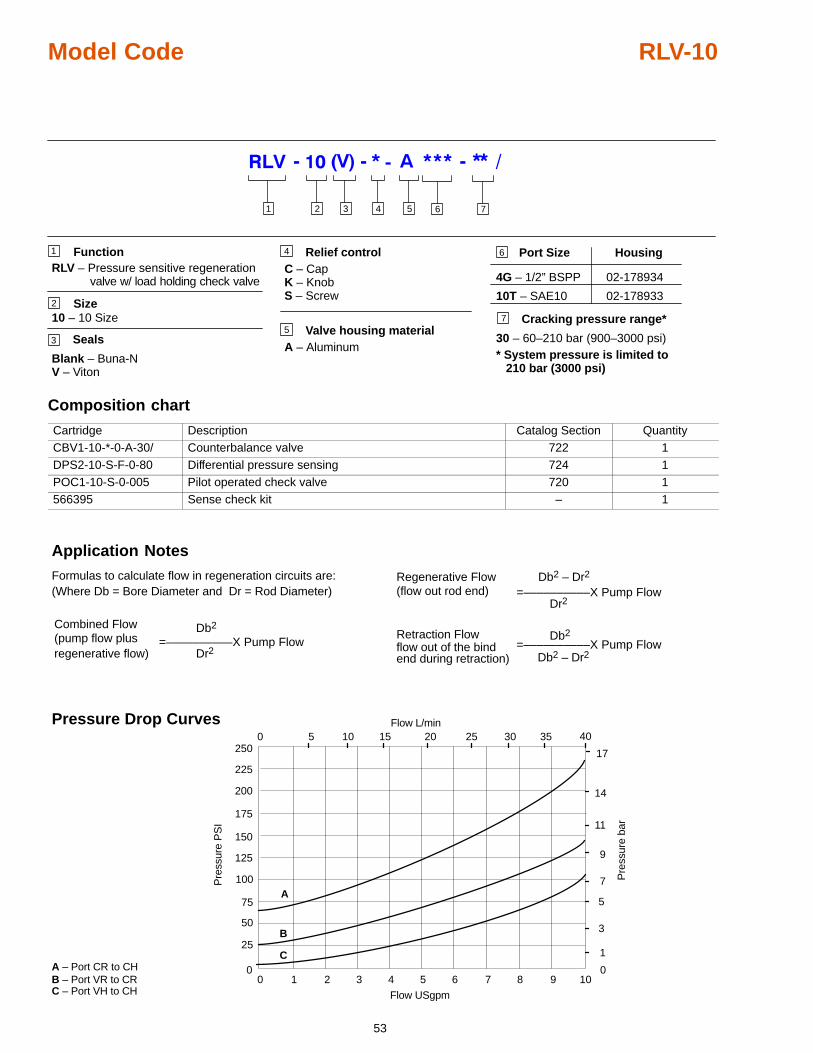
53
Model Code RLV-10
7
Function
Size10 – 10 Size
Seals
Blank – Buna-NV – Viton
Valve housing materialA – Aluminum
Port Size Housing
4G – 1/2” BSPP 02-178934
10T – SAE10 02-178933
1
2
35
Cracking pressure range*
30 – 60–210 bar (900–3000 psi)
6Relief controlC – CapK – KnobS – Screw
4
2 3 4 51 6 7
RLV – Pressure sensitive regenerationvalve w/ load holding check valve
* System pressure is limited to 210 bar (3000 psi)
Composition chart
Cartridge Description Catalog Section QuantityCBV1-10-*-0-A-30/ Counterbalance valve 722 1DPS2-10-S-F-0-80 Differential pressure sensing 724 1POC1-10-S-0-005 Pilot operated check valve 720 1566395 Sense check kit – 1
0 1 2 3 4 5 6 7 8 9 10
25
50
75
100
125
150
175
200
225
250
0
5 10 15 20 25
1
7
9
11
14
A – Port CR to CHB – Port VR to CR
A
B
Pre
ssur
e P
SI
Pre
ssur
e ba
r
Flow USgpm
Flow L/min
3
5
0
30 35 40
17
0
C – Port VH to CH
C
Pressure Drop Curves
Formulas to calculate flow in regeneration circuits are:(Where Db = Bore Diameter and Dr = Rod Diameter)
Regenerative Flow Db2 – Dr2
Db2 – Dr2
(flow out rod end)
=––––––––––X Pump FlowDr2
Combined Flow(pump flow plusregenerative flow)
Retraction FlowDb2
flow out of the bindend during retraction)
=––––––––––X Pump FlowDr2
=––––––––––X Pump FlowDb2
Application Notes
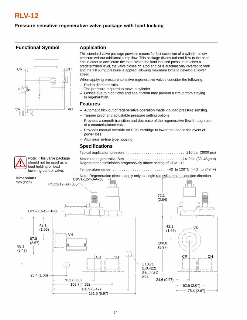
54
RLV-12Pressure sensitive regenerative valve package with load locking
ApplicationThis standard valve package provides means for fast extension of a cylinder at lowpressure without additional pump flow. This package diverts rod end flow to the headend in order to accelerate the load. When the load induced pressure reaches apredetermined level, the valve closes off. Rod end oil is automatically diverted to tankand the full pump pressure is applied, allowing maximum force to develop at lowerspeed.
When applying pressure sensitive regenerative valves consider the following:– Rod to diameter ratio.– The pressure required to move a cylinder.– Losses due to high flows and seal friction may prevent a circuit from staying
in regeneration.
Features– Automatic kick out of regenerative operation made via load pressure sensing.– Tamper proof and adjustable pressure setting options.– Provides a smooth transition and decrease of the regenerative flow through use
of a counterbalance valve.– Provides manual override on POC cartridge to lower the load in the event of
power loss.– Aluminum in-line type housing
SpecificationsTypical application pressure 210 bar (3000 psi). . . . . . . . . . . . . . . . . . . . . . . . . . . . . . . .
Maximum regenerative flow 114 l/min (30 USgpm). . . . . . . . . . . . . . . . . . . . . . . . . . . . . . Regeneration diminishes progressively above setting of CBV1-12.
Temperature range –40 to 120�C (–40� to 248�F). . . . . . . . . . . . . . . . . . . . . . . . . . . . .
Note: Regeneration circuits apply only to single rod cylinders in extention direction.
Functional Symbol
Dimensionsmm (inch)
Note: This valve packageshould not be used as aload holding or loadlowering control valve.
52,5 (2.07)
67,8(2.67)
CBV1-12-*-0-A–30POC1-12-S-0-005
DPS2-16-S-F-0-80
88,1(3.47)
42,1(1.66)
25,4 (1.00)
138,9 (5.47)
76,2 (3.00)109,7 (4.32)
151,6 (5.97)
100,8(3.97)
42,1(1.66)
72,1(2.84)
VR
CHCRCHCR
VH
75,4 (2.97)
24,6 (0.97)
VR VH
CR CH
∅ 10,71(∅ 0.422)dia. thru 2plcs.
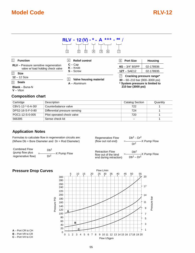
55
Model Code RLV-12
7
Function
Size12 – 12 Size
Seals
Blank – Buna-NV – Viton
Valve housing materialA – Aluminum
Port Size Housing
6G – 3/4” BSPP 02-178936
12T – SAE12 02-178935
1
2
35
Cracking pressure range*30 – 60–210 bar (900–3000 psi)
6Relief controlC – CapK – KnobS – Screw
4
2 3 4 51 6 7
RLV – Pressure sensitive regenerationvalve w/ load holding check valve
* System pressure is limited to 210 bar (3000 psi)
Composition chart
Cartridge Description Catalog Section QuantityCBV1-12-*-0-A-30/ Counterbalance valve 722 1DPS2-16-S-F-0-80 Differential pressure sensing 724 1POC1-12-S-0-005 Pilot operated check valve 720 1566395 Sense check kit – 1
0 1 2 3 4 5 6 7 8 9 10 11 12 13 14 15
204060
80
100
120140
160180
200220
240260
280300
0
5 10 15 20 25 30 35 40 45 50 55
1
3
5
7
9
11
14
17
20
A – Port CR to CHB – Port VR to CR
A
B
Pre
ssur
e P
SI
Pre
ssur
e ba
r
Flow USgpm
Flow L/min
C – Port VH to CH16 17 18 19 20
C
Pressure Drop Curves
Formulas to calculate flow in regeneration circuits are:(Where Db = Bore Diameter and Dr = Rod Diameter)
Regenerative Flow Db2 – Dr2
Db2 – Dr2
(flow out rod end)
=––––––––––X Pump FlowDr2
Combined Flow(pump flow plusregenerative flow)
Retraction FlowDb2
flow out of the bindend during retraction)
=––––––––––X Pump FlowDr2
=––––––––––X Pump FlowDb2
Application Notes
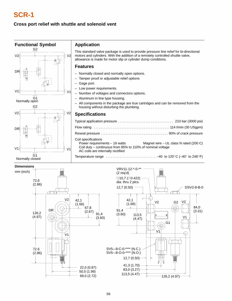
56
SCR-1Cross port relief with shuttle and solenoid vent
42,1(1.66)
ApplicationThis standard valve package is used to provide pressure line relief for bi-directionalmotors and cylinders. With the addition of a remotely controlled shuttle valve,allowance is made for motor slip or cylinder dump conditions.
Features– Normally closed and normally open options.– Tamper proof or adjustable relief options– Gage port.
– Low power requirements.– Number of voltages and connectors options.
– Aluminum in line type housing.– All components in the package are true cartridges and can be removed from the
housing without disturbing the plumbing.
SpecificationsTypical application pressure 210 bar (3000 psi). . . . . . . . . . . . . . . . . . . . . . . . . . . . . . . .
Flow rating 114 l/min (30 USgpm). . . . . . . . . . . . . . . . . . . . . . . . . . . . . . . . . . . . . . . . . . . .
Reseat pressure 90% of crack pressure. . . . . . . . . . . . . . . . . . . . . . . . . . . . . . . . . . . . . . .
Coil specificationsPower requirements – 16 watts Magnet wire – UL class N rated (200 C)Coil duty – continuous from 85% to 110% of nominal voltageAC coils are internally rectified
Temperature range –40 to 120�C (–40� to 248�F). . . . . . . . . . . . . . . . . . . . . . . . . . . . .
Dimensions
mm (inch)
Functional Symbol
42,1(1.66)
91,4(3.60)
∅ 10,7 (∅ 0.422)dia. thru 2 plcs.
50,5 (1.99)
72,6(2.86)
126,2(4.97)
72.6(2.86)
67,8(2.67)
91,4(3.60)
69,0 (2.72)
22,0 (0.87)
V2
DR
V1
VRV11-12-*-0-**(2 req’d)
DSV2-8-B-0
113,5(4.47) V1
V2G2
G1
V1
V2
SV5-–8-C-0-**** (N.C.)SV5-–8-O-0-**** (N.O.)
12,7 (0.50)
126,2 (4.97)
83,0 (3.27)41,3 (1.70)
12,7 (0.50)
84,0(3.31)
V2
DR
V1
G2
V2
V1
G1
V2
DR
V1
G2
V2
V1
G1
Normally open
Normally closed
113,5 (4.47)
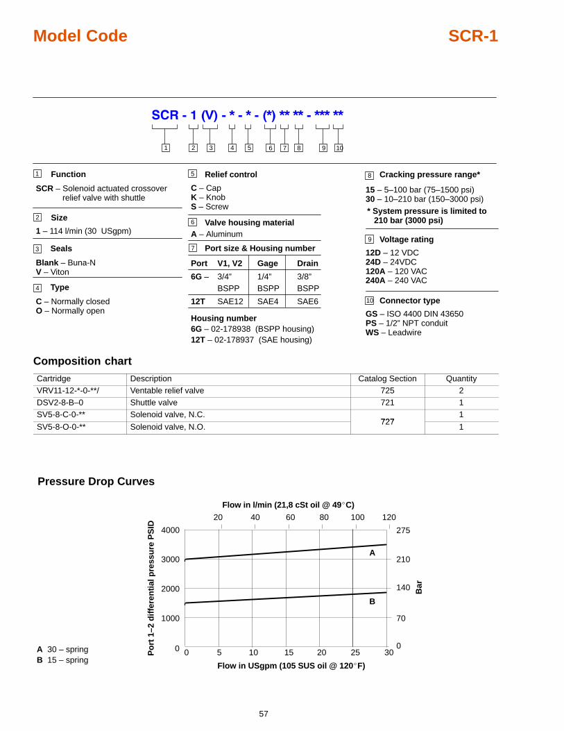
57
Model Code SCR-1
8
2 3 4 51
SCR – Solenoid actuated crossover relief valve with shuttle
Function
Size
1 – 114 l/min (30 USgpm)
Seals
Blank – Buna-NV – Viton
Valve housing materialA – Aluminum
Port size & Housing number
6G – 02-178938 (BSPP housing)12T – 02-178937 (SAE housing)
6
1
2
3
6
Cracking pressure range*
15 – 5–100 bar (75–1500 psi)30 – 10–210 bar (150–3000 psi)
7
7
Relief control
C – CapK – KnobS – Screw
5
8 9 10
Type
C – Normally closedO – Normally open
4
Port V1, V2 Gage Drain
6G – 3/4” 1/4” 3/8”BSPP BSPP BSPP
12T SAE12 SAE4 SAE6
9 Voltage rating
12D – 12 VDC24D – 24VDC120A – 120 VAC240A – 240 VAC
10 Connector type
GS – ISO 4400 DIN 43650PS – 1/2” NPT conduitWS – Leadwire
* System pressure is limited to 210 bar (3000 psi)
Housing number
Composition chart
Cartridge Description Catalog Section QuantityVRV11-12-*-0-**/ Ventable relief valve 725 2DSV2-8-B–0 Shuttle valve 721 1SV5-8-C-0-** Solenoid valve, N.C.
7271
SV5-8-O-0-** Solenoid valve, N.O.727
1
0
1000
2000
3000
4000
20 40 60 80 100 120
0 5 10 15 20 25 30
70
140
210
Bar
Po
rt 1
–2 d
iffe
ren
tial
pre
ssu
re P
SID 275
0
Flow in l/min (21,8 cSt oil @ 49�C)
Flow in USgpm (105 SUS oil @ 120�F)
A
B
Pressure Drop Curves
AB
30 – spring15 – spring