2-way cartridge valves; pressure functions cartridge
TRANSCRIPT
LC; LFA 1/68 RE 21 050/02.03
© 2003by Bosch Rexroth AG, Industrial Hydraulics, D-97813 Lohr am Main
All rights reserved. No part of this document may be reproduced or stored, processed, duplicated or circulated usingelectronic systems, in any form or by any means, without the prior written authorisation of Bosch Rexroth AG.In the event of contravention of the above provisions, the contravening party is obliged to pay compensation.
Overview of contents
Contents Page
Function, section, symbols– General 2– Pressure relief function 2– Pressure reducing function 2 to 3– Pressure sequencing function 3– Cavity and porting pattern 4
Pressure relief function:– Cartridge valve type LC . DB…:
•Ordering details 5•Symbols 5•Technical data 5•Characteristic curves 6 to 11•Seal kits 12•Compression springs 12•Preferred types 12
– Control cover type LFA . DB…:•Ordering details (general) 13 to 14•Technical data 14•Pilot valves 15•Symbols (basic symbols) 16•R-rings for pilot oil connections 17•Seal kits 17•Fixing screws 17• Orifice dimensions 17
RE 21 050/02.03Replaces: 02.99
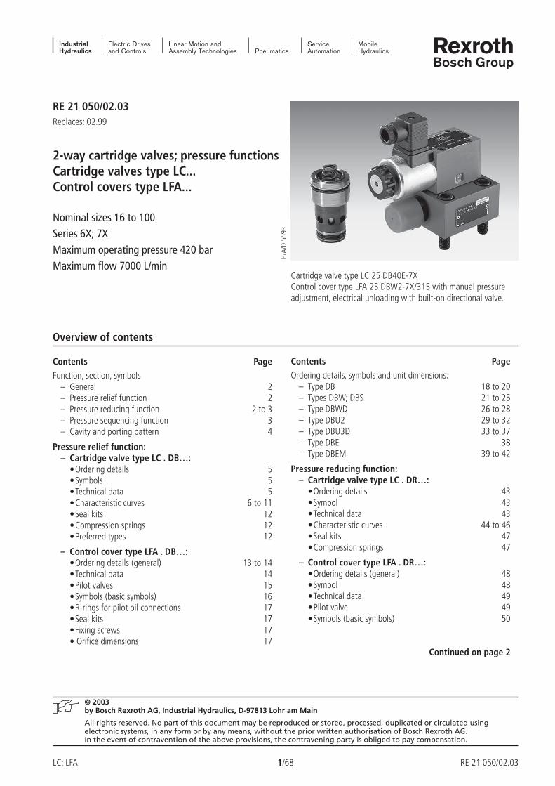
2-way cartridge valves; pressure functionsCartridge valves type LC...Control covers type LFA...
Nominal sizes 16 to 100Series 6X; 7XMaximum operating pressure 420 barMaximum flow 7000 L/min
Cartridge valve type LC 25 DB40E-7XControl cover type LFA 25 DBW2-7X/315 with manual pressureadjustment, electrical unloading with built-on directional valve.
H/A/
D 55
93
Contents Page
Ordering details, symbols and unit dimensions:– Type DB 18 to 20– Types DBW; DBS 21 to 25– Type DBWD 26 to 28– Type DBU2 29 to 32– Type DBU3D 33 to 37– Type DBE 38– Type DBEM 39 to 42
Pressure reducing function:– Cartridge valve type LC . DR…:
•Ordering details 43•Symbol 43•Technical data 43•Characteristic curves 44 to 46•Seal kits 47•Compression springs 47
– Control cover type LFA . DR…:•Ordering details (general) 48•Symbol 48•Technical data 49•Pilot valve 49•Symbols (basic symbols) 50
Continued on page 2
RE 21 050/02.99 2/68 LC; LFA
F**
X
A
YB
X** T
B
A
X YX** F**
A
4
6
1
3
2
5
B
Overview of contentsContents Page
•R-rings for the pilot oil connections 51•Fixing screws 51• General dimensions 52
Ordering details, symbols and unit dimensions:
– Type DR 53 to 54– Type DRW 55 to 56– Types DREV; DREZ 57 to 58– Types DREWV; DREWZ
Contents Page
Pressure sequencing function:– Control cover type LFA . DZ…:
•Ordering details (general) 61•Symbols (basic symbols) 61•Technical data 62•R-rings for the pilot oil connections 62• Seal kits 63•Fixing screws 63• Orifice dimensions 63
Ordering details, symbols and unit dimensions:
– Type DZ 64 to 65– Type DZW 66 to 67
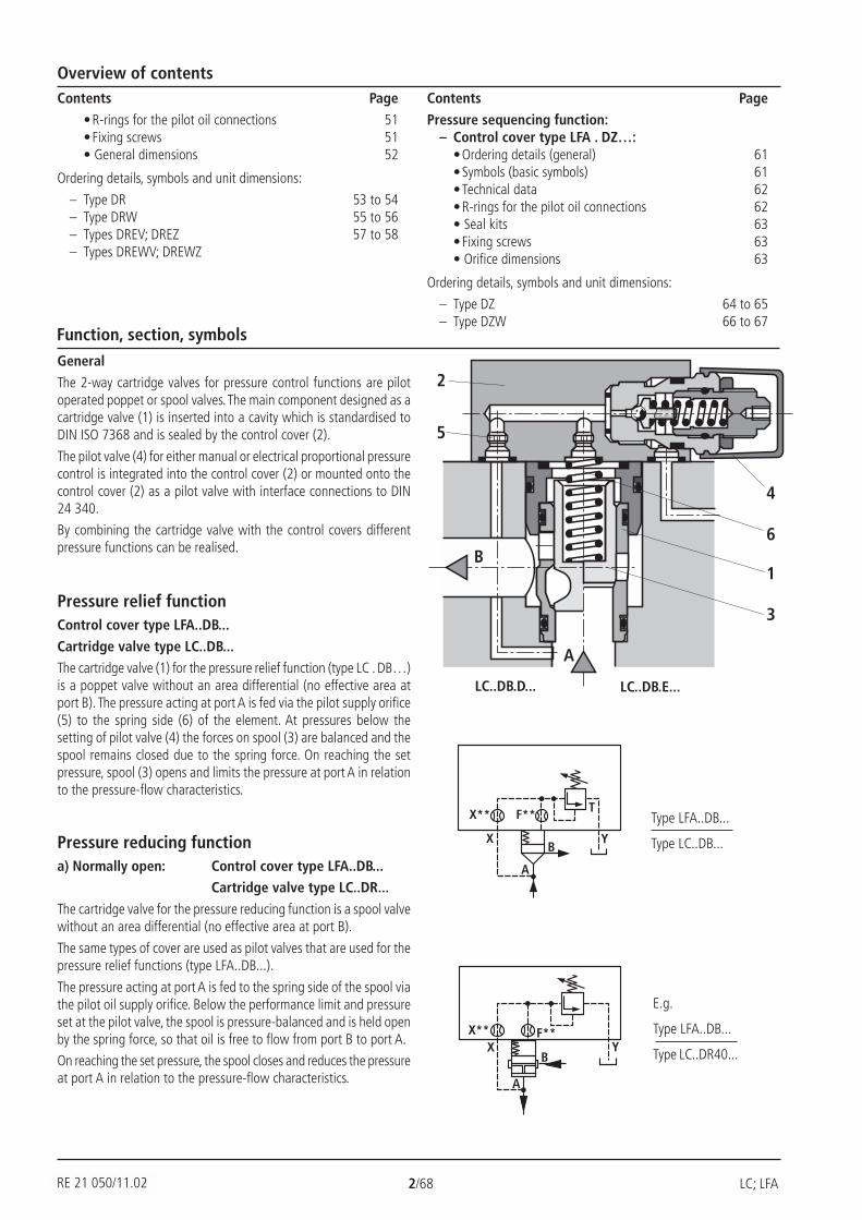
Function, section, symbolsGeneral
The 2-way cartridge valves for pressure control functions are pilotoperated poppet or spool valves. The main component designed as acartridge valve (1) is inserted into a cavity which is standardised toDIN ISO 7368 and is sealed by the control cover (2).
The pilot valve (4) for either manual or electrical proportional pressurecontrol is integrated into the control cover (2) or mounted onto thecontrol cover (2) as a pilot valve with interface connections to DIN24 340.
By combining the cartridge valve with the control covers differentpressure functions can be realised.
LC..DB.D... LC..DB.E...
Pressure relief functionControl cover type LFA..DB...
Cartridge valve type LC..DB...The cartridge valve (1) for the pressure relief function (type LC . DB…)is a poppet valve without an area differential (no effective area atport B). The pressure acting at port A is fed via the pilot supply orifice(5) to the spring side (6) of the element. At pressures below thesetting of pilot valve (4) the forces on spool (3) are balanced and thespool remains closed due to the spring force. On reaching the setpressure, spool (3) opens and limits the pressure at port A in relationto the pressure-flow characteristics.
Pressure reducing functiona) Normally open: Control cover type LFA..DB...
Cartridge valve type LC..DR...
The cartridge valve for the pressure reducing function is a spool valvewithout an area differential (no effective area at port B).
The same types of cover are used as pilot valves that are used for thepressure relief functions (type LFA..DB...).
The pressure acting at port A is fed to the spring side of the spool viathe pilot oil supply orifice. Below the performance limit and pressureset at the pilot valve, the spool is pressure-balanced and is held openby the spring force, so that oil is free to flow from port B to port A.
On reaching the set pressure, the spool closes and reduces the pressureat port A in relation to the pressure-flow characteristics.
Type LFA..DB...
Type LC..DB...
E.g.
Type LFA..DB...
Type LC..DR40...
RE 21 050/11.02

LC; LFA 3/68 RE 21 050/02.99
X YX** F**
M
A
BZ2
X
A
BYZ2 Z1
HD ND
pS
RV
X
A
BYZ2 Z1
Function, symbols
b) Normally closed: Control cover type LFA..DR...
Cartridge valve type LC..DB40D...
For the pressure reducing function with opening characteristics apressure relief valve cartridge (type LC..DB40D...) and a control coverwith a pressure reducing valve (type LFA..DR...) as the pilot valve areused. The pilot oil is fed from port A via the pilot supply orifice andthe open pilot valve to side B.
The main spool opens and allows free-flow from port A to port B.
On reaching the set pressure, the spool closes and reduces the pressureat port B in relation to the pressure-flow characteristics. Possible excesspressures occurring on the secondary side are led away to tank viathe third port of the pilot valve. By fitting a directional valve, an addi-tional isolating function can also be attained (type LFA..DRW...).
Example 2: (circuit for the pressure dependent sequencing of a2nd system)
With this circuit, oil is allowed to flow into system 2 when the pressurein system 1 has reached a pre-set value. The pilot oil supply is internalfrom port A of the main valve.
System 2
Circuit examples
Example 1: (circuit for the pressure dependent unloading of thelow pressure system)
In the circuit shown, the system is fed by a high pressure pump anda low pressure pump. The system pressure pS acts externally from thehigh pressure side via the pilot oil port X on the pilot valve which, onreaching the set pressure, switches the low pressure side to give zeropressure circulation. The check valve RV (not included within the scopeof supply) prevents the high pressure system from flowing into thelow pressure system which is now at zero pressure.
Pressure sequencing functionControl cover type LFA..DZ...Cartridge valve type LC..DB...
This function enables a pressure-dependent sequencing of a secondsystem.
The required sequencing pressure is set by the pilot valve which isintegrated into the control cover.
The pilot oil supply may be either external (pilot oil port X) or internal(from port A via pilot oil port X or Z2).
The spring chamber of the pilot control is drained at zero pressurevia ports Y or Z1 to tank.
System 1
E.g.
Type LFA..DR...
Type LC..DB40D...
E.g.
Type LFA..DZ...XY
Type LC..DB20D...
E.g.
Type LFA..DZ...Y
Type LC..DB20D...
When the pressure set at the pilot control spring is reached, the pilotvalve switches and unloads the spring chamber of the main valve totank. The main spools opens and makes the connection from port Ato B possible.
In version LFA..DZW..., the required spool position may be selectedby means of an electrically operated pilot valve (not included withthe scope of control cover LFA..DZW... supply) in addition to the nor-mal hydraulic control.
RE 21 050/02.99 4/68 LC; LFA
=X
=Y
=Z
Rmax 4
Rmax 8
RZ 10
L1
L2±0,2
L5±0,2
L4±0
,2L4
±0,2
L4±0,2L4±0,2
L3±0
,2
L1
4 x D5; H4
ØD7H13; 10 ØD6 max.(X,Y,Z1,Z2)
Z1
YX
Z2
L2±0
,2L5±0
,2
ØD6 max.(X,Y,Z1,Z2)
ØD7H13; 10
5
8L3±0,2
6
8 x D5; H4
ØD7H13; 10
ØD6 max.(X,Y,Z1,Z2)
L2±0
,3
L1
35° 22,5°
45°
Z1
Y
Z2
X
5
X
Y
AØD1H7
W
T
H8 15
°
H1(
H1*
)
ØD
3(D
3*)
15°
H9
A
B
ØD2
ØD4H7
H7
H6
H5
H3 ±
0,1
H2+
0,1
A0,05
Z
Z
Z
7 1
7 13 2 4
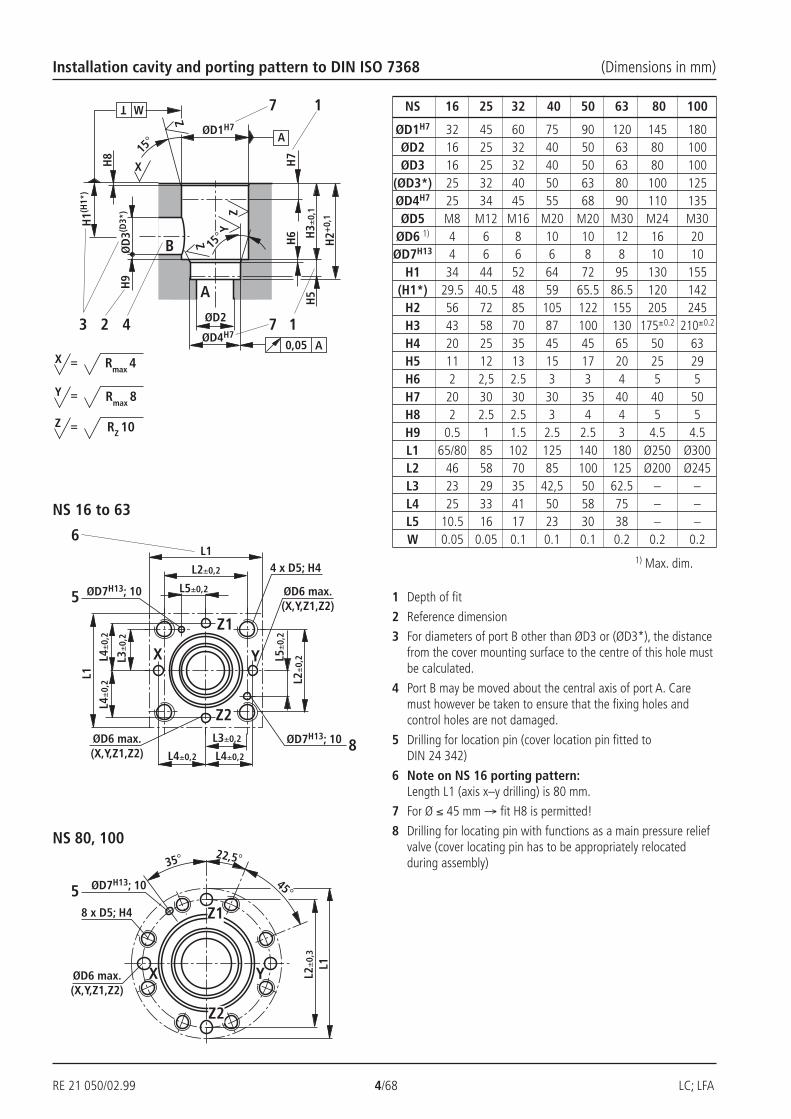
Installation cavity and porting pattern to DIN ISO 7368 (Dimensions in mm)
NS 80, 100
NS 16 to 63
1 Depth of fit
2 Reference dimension
3 For diameters of port B other than ØD3 or (ØD3*), the distancefrom the cover mounting surface to the centre of this hole mustbe calculated.
4 Port B may be moved about the central axis of port A. Caremust however be taken to ensure that the fixing holes andcontrol holes are not damaged.
5 Drilling for location pin (cover location pin fitted toDIN 24 342)
6 Note on NS 16 porting pattern:Length L1 (axis x–y drilling) is 80 mm.
7 For Ø ≤ 45 mm → fit H8 is permitted!
8 Drilling for locating pin with functions as a main pressure reliefvalve (cover locating pin has to be appropriately relocatedduring assembly)
1) Max. dim.
NS 16 25 32 40 50 63 80 100
ØD1H7 32 45 60 75 90 120 145 180ØD2 16 25 32 40 50 63 80 100ØD3 16 25 32 40 50 63 80 100
(ØD3*) 25 32 40 50 63 80 100 125ØD4H7 25 34 45 55 68 90 110 135ØD5 M8 M12 M16 M20 M20 M30 M24 M30
ØD6 1) 4 6 8 10 10 12 16 20ØD7H13 4 6 6 6 8 8 10 10
H1 34 44 52 64 72 95 130 155(H1*) 29.5 40.5 48 59 65.5 86.5 120 142
H2 56 72 85 105 122 155 205 245H3 43 58 70 87 100 130 175±0.2 210±0.2
H4 20 25 35 45 45 65 50 63H5 11 12 13 15 17 20 25 29H6 2 2,5 2.5 3 3 4 5 5H7 20 30 30 30 35 40 40 50H8 2 2.5 2.5 3 4 4 5 5H9 0.5 1 1.5 2.5 2.5 3 4.5 4.5L1 65/80 85 102 125 140 180 Ø250 Ø300L2 46 58 70 85 100 125 Ø200 Ø245L3 23 29 35 42,5 50 62.5 – –L4 25 33 41 50 58 75 – –L5 10.5 16 17 23 30 38 – –W 0.05 0.05 0.1 0.1 0.1 0.2 0.2 0.2
LC; LFA 5/68 RE 21 050/02.99
A
B
A
B
A
B
A
B
Pressure relief function
Ordering details: pressure relief cartridge valve (without control cover)
No code = NBR sealsV FKM seals
(other seals on request)
Attention!The compatibility of the seals and pressure
fluid has to be taken into account!
7X = (NS 16 to 63) Series 70 to 79 (70 to 79: unchanged installation and connection dimensions)
6X = (NS 80 and 100) Series 60 to 69 (60 to 69: unchanged installation and connection dimensions)
E = Poppet valve without orifice (standard)D = Spool poppet valve without orifice (standard)A = Poppet valve with orificeB = Spool poppet valve with orifice
Nominal size 16 = 16Nominal size 25 = 25Nominal size 32 = 32Nominal size 40 = 40Nominal size 50 = 50Nominal size 63 = 63Nominal size 80 = 80Nominal size 100 = 100
Opening pressure approx. 0 bar (without spring) = 00Opening pressure approx. 2 bar = 20Opening pressure approx. 3 bar = 30 1)
Opening pressure approx. 4 bar = 40Opening pressure approx. 5 bar = 50 2)
Opening pressure approx. 8 bar = 80 3)
(Series 7X)
(Series 6X)
LC DB
Preferred¡ types, see page 12, are
readily available!
1) Opening pressure 3.0 bar only with NS16 for fitting a pilotoperated pressure relief valve type DBC . -5X/…SO187 (seecatalogue sheet RE 25 802)
2) Only with NS 16, 25 and 323) Special installation space is required (see page 12)
Symbols: cartridge valves (for versions see ordering details)
Poppet valve without orificeVersion „E“
Poppet valve with orificeVersion „A“
Spool poppet valve without orificeVersion „D“
Spool poppet valve with orificeVersion „B“
Pressure fluid Mineral oil (HL, HLP) to DIN 51 524 1);Fast bio-degradable pressure fluids toVDMA 24 568 (also see RE 90 221); HETG (rape seed oil) 1);HEPG (polyglycols) 2); HEES (synthetic ester) 2);Other pressure fluids on request
Pressure fluid temperature range °C – 30 to + 80 for NBR seals
– 20 to + 80 for FKM seals
Viscosity range mm2/s 2.8 to 380
Cleanliness class to ISO code Maximum permissible degree of contamination of the pressurefluid is to ISO 4406 (C) class 20/18/15 3)
2-way cartridge valve
Maximum operating pressure – Ports A and B bar 420
Maximum flow (recommended) NS 16 25 32 40 50 63 80 100
– Poppet valve cartridges „E“ and „A“ L/min 300 450 600 1000 1600 2500 4500 7000
– Spool valve cartridges „D“ and „B“ L/min 175 300 450 700 1400 1750 3200 4900
Technical data (for applications outside these parameters, please consult us!)
1) Suitable for NBR and FKM seals2) Only suitable for FKM seals
3) The cleanliness class stated for the components must be adhered too in hydraulic systems. Effective filtration prevents faults fromoccurring and at the same time increases the component service life.For the selection of filters see catalogue sheets RE 50 070, RE 50 076 and RE 50 081.
RE 21 050/02.03
RE 21 050/02.99 6/68 LC; LFA
50 100 150 200 250
5
10
15
0
..DB40..
..DB20..
50 250
50
350
0 100 150 200
100
150
200
250
300
50 100 150 200 250
5
10
15
0
..DB40..
..DB20..
50 250
50
350
0 100 150 200
100
150
200
250
300
50 100 150 200 250
5
10
15
0
..DB40..
..DB20..
50 250
50
350
0 100 150 200
100
150
200
250
300
50 100 150 200 250
5
10
15
0
..DB40..
..DB20..
50 250
50
350
0 100 150 200
100
150
200
250
300
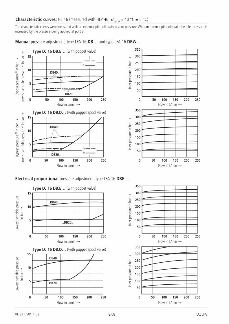
Characteristic curves: NS 16 (measured with HLP 46; ϑ oil -/ = 40 °C ± 5 °C)
The characteristic curves were measured with an external pilot oil drain at zero pressure. With an internal pilot oil drain the inlet pressure isincreased by the pressure being applied at port B.
Manual pressure adjustment, type LFA 16 DB… and type LFA 16 DBW…
Type LC 16 DB.E… (with poppet valve)
Bypa
ss p
ress
ure1)
in b
ar →
Low
est s
etta
ble
pres
sure
2) in
bar
→
Flow in L/min → Flow in L/min →
Inle
t pre
ssur
e in
bar
→
Type LC 16 DB.D… (with poppet spool valve)
Bypa
ss p
ress
ure
1) in
bar
→
Low
est s
etta
ble
pres
sure
2) in
bar
→
Flow in L/min → Flow in L/min →
Inle
t pre
ssur
e in
bar
→
Electrical proportional pressure adjustment, type LFA 16 DBE…
Type LC 16 DB.E… (with poppet valve)
Low
est s
etta
ble
pres
sure
in b
ar →
Flow in L/min → Flow in L/min →
Inle
t pre
ssur
e in
bar
→
Type LC 16 DB.D… (with poppet spool valve)
Flow in L/min → Flow in L/min →
Inle
t pre
ssur
e in
bar
→
Low
est s
etta
ble
pres
sure
in b
ar →
1)
2)
1)
2)
RE 21 050/11.02
LC; LFA 7/68 RE 21 050/02.99
100 400
5
10
15
0
..DB40..
..DB20..
100
50
350
0
100
150
200
250
300
200 300 200 300 400150 250 35050
100 400
5
10
15
0
..DB40..
..DB20..
100
50
350
0
100
150
200
250
300
200 300 200 300 40050 150 250 350
100 400
5
10
15
0
..DB40..
..DB20..
100
50
350
0
100
150
200
250
300
200 300 200 300 400150 250 35050
100 400
5
10
15
0
..DB40..
..DB20..
100
50
350
0
100
150
200
250
300
200 300 200 300 40050 150 250 350
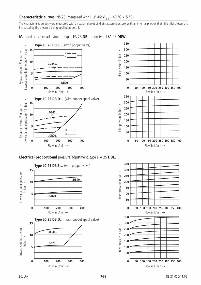
Characteristic curves: NS 25 (measured with HLP 46; ϑ oil = 40 °C ± 5 °C)
The characteristic curves were measured with an external pilot oil drain at zero pressure. With an internal pilot oil drain the inlet pressure isincreased by the pressure being applied at port B.
Manual pressure adjustment, type LFA 25 DB… and type LFA 25 DBW…
Type LC 25 DB.E… (with poppet valve)
Bypa
ss p
ress
ure
1) in
bar
→
Low
est s
etta
ble
pres
sure
2) in
bar
→
Flow in L/min → Flow in L/min →
Inle
t pre
ssur
e in
bar
→
Type LC 25 DB.D… (with poppet spool valve)
Bypa
ss p
ress
ure
1) in
bar
→
Low
est s
etta
ble
pres
sure
2) in
bar
→
Flow in L/min → Flow in L/min →
Inle
t pre
ssur
e in
bar
→
Electrical proportional pressure adjustment, type LFA 25 DBE…
Type LC 25 DB.E… (with poppet valve)
Flow in L/min → Flow in L/min →
Inle
t pre
ssur
e in
bar
→
Type LC 25 DB.D… (with poppet spool valve)
Flow in L/min → Flow in L/min →
Inle
t pre
ssur
e in
bar
→
Low
est s
etta
ble
pres
sure
in b
ar →
Low
est s
etta
ble
pres
sure
in b
ar →
1)
2)
1)
2)
RE 21 050/11.02
RE 21 050/02.99 8/68 LC; LFA
50
350
0
100
150
200
250
300
600100 200 300 400 500100 600
5
10
15
0
..DB40..
..DB20..
200 300 400 500
50
350
0
100
150
200
250
300
600100 200 300 400 500100 600
5
10
15
0
..DB40..
..DB20..
200 300 400 500
100 600
5
10
15
0
..DB40..
..DB20..50
350
0
100
150
200
250
300
600100200 300 400 500 200 300 400 500
100 600
5
10
15
0
..DB40..
..DB20..50
350
0
100
150
200
250
300
600100200 300 400 500 200 300 400 500
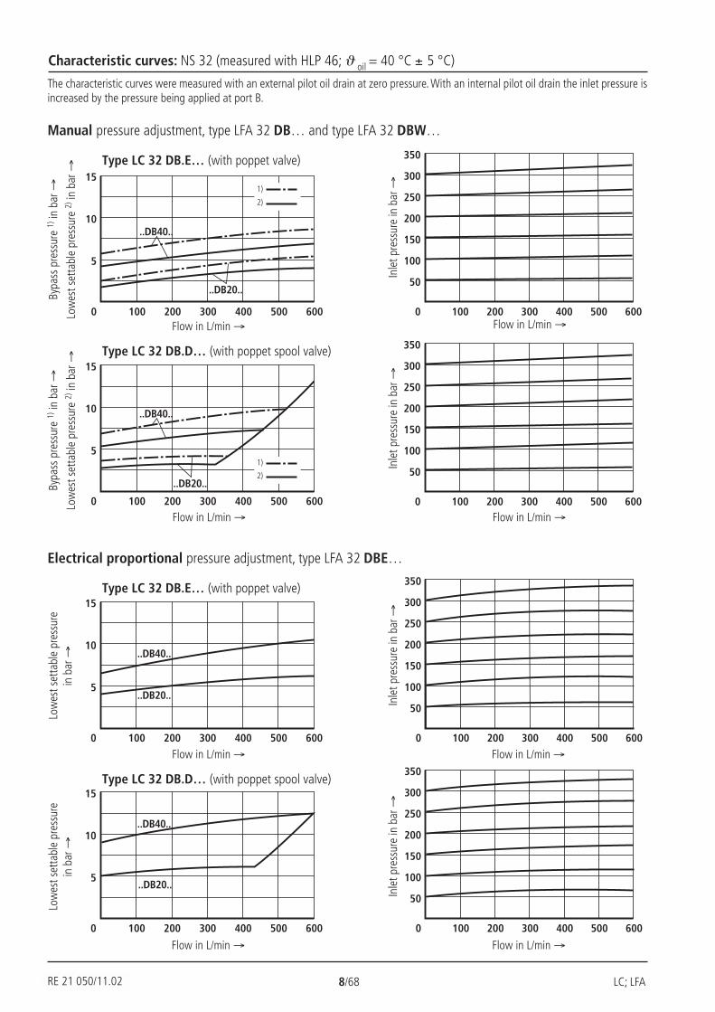
Characteristic curves: NS 32 (measured with HLP 46; ϑ oil = 40 °C ± 5 °C)
The characteristic curves were measured with an external pilot oil drain at zero pressure. With an internal pilot oil drain the inlet pressure isincreased by the pressure being applied at port B.
Manual pressure adjustment, type LFA 32 DB… and type LFA 32 DBW…
Type LC 32 DB.E… (with poppet valve)
Bypa
ss p
ress
ure
1) in
bar
→
Low
est s
etta
ble
pres
sure
2) in
bar
→
Flow in L/min → Flow in L/min →
Inle
t pre
ssur
e in
bar
→
Type LC 32 DB.D… (with poppet spool valve)
Bypa
ss p
ress
ure
1) in
bar
→
Low
est s
etta
ble
pres
sure
2) in
bar
→
Flow in L/min → Flow in L/min →
Inle
t pre
ssur
e in
bar
→
Electrical proportional pressure adjustment, type LFA 32 DBE…
Type LC 32 DB.E… (with poppet valve)
Low
est s
etta
ble
pres
sure
in b
ar →
Flow in L/min → Flow in L/min →
Inle
t pre
ssur
e in
bar
→
Type LC 32 DB.D… (with poppet spool valve)
Flow in L/min → Flow in L/min →
Inle
t pre
ssur
e in
bar
→
Low
est s
etta
ble
pres
sure
in b
ar →
1)
2)
1)
2)
RE 21 050/11.02
LC; LFA 9/68 RE 21 050/02.99
15
20
10
5
0 200 400 600 800 1000
..DB40..
..DB20..
1000800600400200
200
250
350
300
150
100
50
0
15
20
10
5
0 200 400 600 800 1000 1000800600400200
200
250
350
300
150
100
50
0
..DB20..
..DB40..
15
20
10
5
0 200 400 600 800 1000
..DB20..
1000800600400200
200
250
350
300
150
100
50
0
..DB40..
15
20
10
5
0 200 400 600 800 1000
..DB40..
..DB20..
1000800600400200
200
250
350
300
150
100
50
0
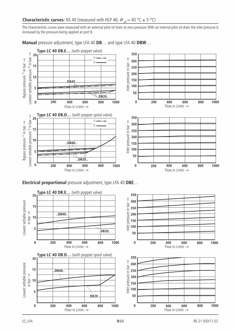
Characteristic curves: NS 40 (measured with HLP 46; ϑ oil = 40 °C ± 5 °C)
The characteristic curves were measured with an external pilot oil drain at zero pressure. With an internal pilot oil drain the inlet pressure isincreased by the pressure being applied at port B.
Manual pressure adjustment, type LFA 40 DB… and type LFA 40 DBW…
Type LC 40 DB.E… (with poppet valve)
Bypa
ss p
ress
ure
1) in
bar
→
Low
est s
etta
ble
pres
sure
2) in
bar
→
Flow in L/min → Flow in L/min →
Inle
t pre
ssur
e in
bar
→
Type LC 40 DB.D… (with poppet spool valve)
Bypa
ss p
ress
ure
1) in
bar
→
Low
est s
etta
ble
pres
sure
2) in
bar
→
Flow in L/min → Flow in L/min →
Inle
t pre
ssur
e in
bar
→
Electrical proportional pressure adjustment, type LFA 40 DBE…
Type LC 40 DB.E… (with poppet valve)
Low
est s
etta
ble
pres
sure
in b
ar →
Flow in L/min → Flow in L/min →
Inle
t pre
ssur
e in
bar
→
Type LC 40 DB.D… (with poppet spool valve)
Flow in L/min → Flow in L/min →
Inle
t pre
ssur
e in
bar
→
Low
est s
etta
ble
pres
sure
in b
ar →
1)
2)
1)
2)
RE 21 050/11.02
RE 21 050/02.99 10/68 LC; LFA
500 1000 1500 2000
15
20
10
5
0
..DB40..
25
30
..DB20..
200
250
350
300
150
100
50
0 500 1000 1500 2000
500 1000 1500 2000
15
20
10
5
0
..DB40..
..DB20..
30
500 1000 1500 2000
200
250
350
300
150
100
50
0
25
15
20
10
5
0 500 1000 1500 2000
25
30
500 1000 1500 2000
200
250
350
300
150
100
50
0
..DB20..
..DB40..
500 1000 1500 2000
200
250
350
300
150
100
50
02000500 1000 1500
15
20
10
5
0
30
..DB20..
..DB40..
25
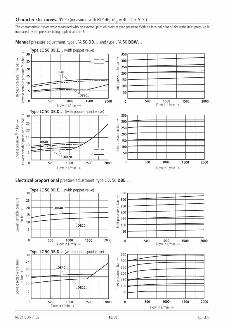
Characteristic curves: NS 50 (measured with HLP 46; ϑ oil = 40 °C ± 5 °C)
The characteristic curves were measured with an external pilot oil drain at zero pressure. With an internal pilot oil drain the inlet pressure isincreased by the pressure being applied at port B.
Manual pressure adjustment, type LFA 50 DB… and type LFA 50 DBW…
Type LC 50 DB.E… (with poppet valve)
Bypa
ss p
ress
ure
1) in
bar
→
Low
est s
etta
ble
pres
sure
2) in
bar
→
Flow in L/min → Flow in L/min →
Inle
t pre
ssur
e in
bar
→
Type LC 50 DB.D… (with poppet spool valve)
Bypa
ss p
ress
ure
1) in
bar
→
Low
est s
etta
ble
pres
sure
2) in
bar
→
Flow in L/min → Flow in L/min →
Inle
t pre
ssur
e in
bar
→
Electrical proportional pressure adjustment, type LFA 50 DBE…
Type LC 50 DB.E… (with poppet valve)
Low
est s
etta
ble
pres
sure
in b
ar →
Flow in L/min → Flow in L/min →
Inle
t pre
ssur
e in
bar
→
Type LC 50 DB.D… (with poppet spool valve)
Inle
t pre
ssur
ein
bar →
Low
est s
etta
ble
pres
sure
in b
ar →
1)
2)
1)
2)
RE 21 050/11.02
Flow in L/min → Flow in L/min →

LC; LFA 11/68 RE 21 050/02.99
500 1000 1500 20000 2500
15
20
10
5
..DB40..
..DB20..
30
200
250
350
300
150
100
50
500 1000 1500 20000 2500
25
500 1000 1500 20000 2500500 1000 1500 20000 2500
..DB40..
200
250
350
300
150
100
50
15
20
10
5
30
..DB20..
25
0 2500500 1000 1500 20000 2500
15
20
10
5
30
200
250
350
300
150
100
50
..DB20..
..DB40..
500 1000 1500 2000
25
2500
15
20
10
5
25
30
200
250
350
300
150
100
50
0500 1000 1500 20000 2500 500 1000 1500 2000
..DB20..
..DB40..
Characteristic curves: NS 63 (measured with HLP 46; ϑ oil = 40 °C ± 5 °C)
The characteristic curves were measured with an external pilot oil drain at zero pressure. With an internal pilot oil drain the inlet pressure isincreased by the pressure being applied at port B.
Manual pressure adjustment, type LFA 63 DB… and type LFA 63 DBW…
Type LC 63 DB.E… (with poppet valve)
Bypa
ss p
ress
ure
1) in
bar
→
Low
est s
etta
ble
pres
sure
2) in
bar
→
Flow in L/min → Flow in L/min →
Inle
t pre
ssur
e in
bar
→
Type LC 63 DB.D… (with poppet spool valve)
Bypa
ss p
ress
ure
1) in
bar
→
Low
est s
etta
ble
pres
sure
2) in
bar
→
Flow in L/min → Flow in L/min →
Inle
t pre
ssur
e in
bar
→
Electrical proportional pressure adjustment, type LFA 63 DBE…
Type LC 63 DB.E… (with poppet valve)
Low
est s
etta
ble
pres
sure
in b
ar →
Flow in L/min → Flow in L/min →
Inle
t pre
ssur
e in
bar
→
Type LC 63 DB.D… (with poppet spool valve)
Flow in L/min → Flow in L/min →
INle
t pre
ssur
e in
bar
→
Low
est s
etta
ble
pres
sure
in b
ar →
1)
2)
1)
2)
RE 21 050/11.02
RE 21 050/02.99 12/68 LC; LFA
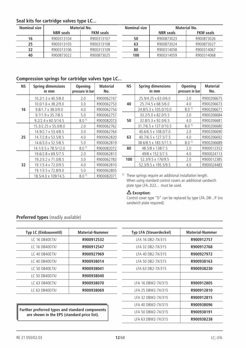
Seal kits for cartridge valves type LC...Nominal size Material No.
NBR seals FKM seals16 R900313104 R90031310725 R900313105 R90031310832 R900313106 R90031310940 R900873022 R900873025
Nominal size Material No.NBR seals FKM seals
50 R900873023 R90087302663 R900873024 R90087302780 R900314058 R900314067
100 R900314059 R900314068
Compression springs for cartridge valves type LC...NS Spring dimensions Opening Material
in mm pressure in bar No.
10.2/1.3 x 40.5/8.0 2.0 R90006274710.0/1.6 x 38.2/9.0 3.0 R900062753
16 9.8/1.7 x 38.0/9.0 4.0 R9000627549.7/1.9 x 35.7/8.5 5.0 R900062757
9.2/2.4 x 60.5/14.5 8.0 1) R90008207315.3/2.25 x 55.0/8.0 2.0 R90006276214.9/2.7 x 53.4/8.5 3.0 R900062764
25 14.7/2.8 x 53.5/8.5 4.0 R90006282014.6/3.0 x 52.5/8.5 5.0 R900062819
14.1/3.5 x 78.5/12.0 8.0 1) R90008207219.6/2.8 x 69.5/7.5 2.0 R90006281319.2/3.2 x 71.0/8.5 3.0 R900062783
32 19.1/3.4 x 72.0/9.5 4.0 R90006281019.1/3.5 x 72.8/9.0 5.0 R90006280518.5/4.0 x 109/14.5 8.0 1) R900082071
NS Spring dimensions Opening Materialin mm pressure in bar No.
25.9/4.25 x 63.0/6.0 2.0 R90020667540 25.7/4.5 x 68.5/6.0 4.0 R900206673
24.8/5.3 x 105.0/10.0 8.0 1) R90020667133.2/5.0 x 82.0/5.5 2.0 R900206684
50 32.8/5.3 x 92.0/6.5 4.0 R90020668131.7/6.5 x 137.0/10.5 8.0 1) R90020668040.6/6.5 x 108.0/7.0 2.0 R900206690
63 40.7/6.5 x 127.5/7.5 4.0 R90020669238.6/8.5 x 183.5/11.5 8.0 1) R900206689
80 48.5/8 x 138/7.5 2.0 R90001235349/8 x 152.5/7.5 4.0 R900024113
100 52.3/9.5 x 176/9.5 2.0 R90001238552.3/9.5 x 195.5/9.5 4.0 R900024483
1) These springs require an additional installation length.When using standard control covers an additional sandwichplate type LFA..D22... must be used.
Exception:Control cover type “D“ can be replaced by type LFA..D8-../F (nosandwich plate required).
RE 21 050/02.03
Preferred types (readily available)
Further preferred types and standard componentsare shown in the EPS (standard price list).
Typ LC (Einbauventil) Material-Nummer
LC 16 DB40E7X/ R900912532
LC 16 DB40D7X/ R900912547
LC 40 DB40E7X/ R900927969
LC 40 DB40D7X/ R900938014
LC 50 DB40E7X/ R900938041
LC 50 DB40D7X/ R900938040
LC 63 DB40E7X/ R900938070
LC 63 DB40D7X/ R900938069
Typ LFA (Steuerdeckel) Material-Nummer
LFA 16 DB2-7X/315 R900912757
LFA 32 DB2-7X/315 R900912768
LFA 40 DB2-7X/315 R900927972
LFA 50 DB2-7X/315 R900938163
LFA 63 DB2-7X/315 R900938230
LFA 16 DBW2-7X/315 R900912805
LFA 25 DBW2-7X/315 R900912810
LFA 32 DBW2-7X/315 R900912815
LFA 40 DBW2-7X/315 R900938096
LFA 50 DBW2-7X/315 R900938191
LFA 63 DBW2-7X/315 R900938238
LC; LFA 13/68 RE 21 050/02.99
LFA A... B...
4
6
7
A...
B...8
5
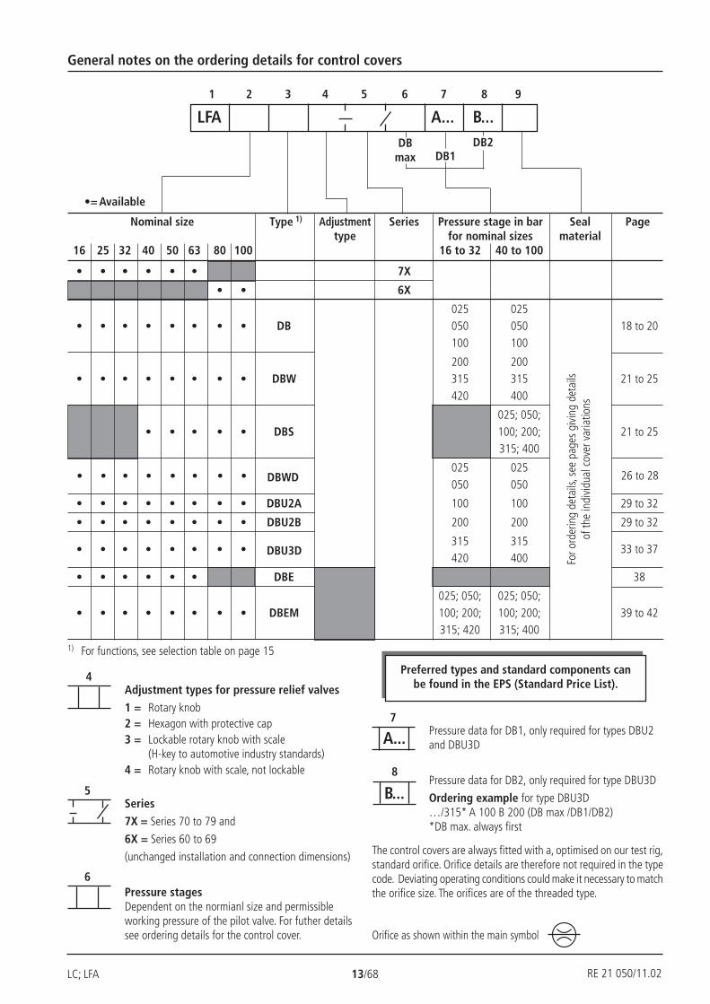
General notes on the ordering details for control covers
1 2 3 4 5 6 7 8 9
Nominal size Type 1) Adjustment Series Pressure stage in bar Seal Pagetype for nominal sizes material
16 25 32 40 50 63 80 100 16 to 32 40 to 100
• • • • • • 7X
• • 6X
025 025• • • • • • • • DB 050 050 18 to 20
100 100
200 200• • • • • • • • DBW 315 315 21 to 25
420 400
025; 050;• • • • • DBS 100; 200; 21 to 25
315; 400
025 025050 050
• • • • • • • • DBU2A 100 100 29 to 32
• • • • • • • • DBU2B 200 200 29 to 32
315 315420 400
• • • • • • DBE 38
025; 050; 025; 050;• • • • • • • • DBEM 100; 200; 100; 200; 39 to 42
315; 420 315; 400
For o
rder
ing
deta
ils, s
ee p
ages
giv
ing
deta
ilsof
the
indi
vidu
al c
over
var
iatio
ns
DB2DBmax DB1
Adjustment types for pressure relief valves
1 = Rotary knob2 = Hexagon with protective cap3 = Lockable rotary knob with scale
(H-key to automotive industry standards)4 = Rotary knob with scale, not lockable
Series
7X = Series 70 to 79 and
6X = Series 60 to 69
(unchanged installation and connection dimensions)
Pressure stagesDependent on the normianl size and permissibleworking pressure of the pilot valve. For futher detailssee ordering details for the control cover.
Pressure data for DB1, only required for types DBU2and DBU3D
Pressure data for DB2, only required for type DBU3D
Ordering example for type DBU3D…/315* A 100 B 200 (DB max /DB1/DB2)*DB max. always first
1) For functions, see selection table on page 15
•= Available
26 to 28• • • • • • • • DBWD
33 to 37• • • • • • • • DBU3D
The control covers are always fitted with a, optimised on our test rig,standard orifice. Orifice details are therefore not required in the typecode. Deviating operating conditions could make it necessary to matchthe orifice size. The orifices are of the threaded type.
Orifice as shown within the main symbol
Preferred types and standard components canbe found in the EPS (Standard Price List).
RE 21 050/11.02
RE 21 050/02.99 14/68 LC; LFA
1) Suitable for NBR and FKM seals2) Only suitable for FKM seals
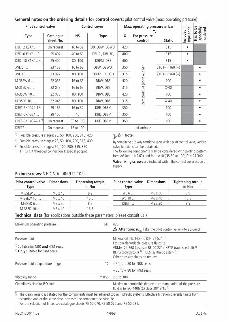
Pressure fluid Mineral oil (HL, HLP) to DIN 51 524 1);Fast bio-degradable pressure fluids toVDMA 24 568 (also see RE 90 221); HETG (rape seed oil) 1);HEPG (polyglycols) 2); HEES (synthetic ester) 2);Other pressure fluids on request
Pressure fluid temperature range °C – 30 to + 80 for NBR seals
– 20 to + 80 for FKM seals
Viscosity range mm2/s 2.8 to 380
Cleanliness class to ISO code Maximum permissible degree of contamination of the pressurefluid is to ISO 4406 (C) class 20/18/15 3)
Technical data (for applications outside these parameters, please consult us!)
General notes on the ordering details for control covers: pilot control valve (max. operating pressure)
1) Possible pressure stages: 25, 50, 100, 200, 315, 4202) Possible pressure stages: 25, 50, 100, 200, 315, 4003) Possible pressure stages: 50, 100, 200, 315, 350
1 = G 1/4 threaded connection T; special poppet
Pilot control valve Control cover Max. operating pressure in barY, T
Type Catalogue NS Type X For pressuresheet No. control Static
DBD. 2 K2X/… 1) On request 16 to 32 DB, DBW, DBWD, 420 315 •
DBD. 6 K1X/… 2) 25 402 40 to 63 DBU2., DBU3D, 400 315 •
DBD. 10 K1X/… 2) 25 402 80, 100 DBEM, DBS 400 315 •
.WE 6 … 23 178 16 to 63 DBW, DBWD, 350 210 (=); 160 (~) •
.WE 10 … 23 327 80, 100 DBU2., DBU3D 315 210 (=); 160 (~) •
M-3SEW 6 … 22 058 16 to 63 DBW, DBS 420 100 •
M-3SED 6 … 22 049 16 to 63 DBW, DBS 315 X-40 •
M-3SEW 10 … 22 075 80, 100 DBW, DBS 420 100 •
M-3SED 10 … 22 045 80, 100 DBW, DBS 315 X-40 •
DBET-5X/.G24-1 3) 29 165 16 to 32 DBE, DBEM 350 100 •
DBET-5X/.G24… 29 165 40 DBE, DBEM 350 100 •
DBET-5X/.YG24-1 3) On request 50 to 100 DBE, DBEM 350 100 •
DBETR… On request 16 to 100 auf Anfrage
Incl
uded
inty
pe c
ode
Has
to
besp
ecia
llyor
dere
d
Zero
pre
ssur
e (u
p to
≈ 2
bar
)
Note:
By combining a 2-way cartridge valve with a pilot control valve, variousvalve functions can be obtained.The following components may be considered with porting patternform A6 (up to NS 63) and form A10 (NS 80 to 100) DIN 24 340.
Valve fixing screws are included within the control cover scope ofsupply.
Fixing screws: S.H.C.S. to DIN 912-10.9
Pilot control valve Dimensions Tightening torqueType in Nm
M-3SEW 6 … M5 x 45 8.9M-3SEW 10 … M6 x 40 15.5M-3SED 6 … M5 x 50 8.9
M-3SED 10 … M6 x 40 15.5
Pilot control valve Dimensions Tightening torqueType in Nm
.WE 6 … M5 x 50 8.9.WE 10 … M6 x 40 15.5DBET … M5 x 30 8.9
Maximum operating pressure bar 420 Attention: pmax Take the pilot control valve into account!
3) The cleanliness class stated for the components must be adhered too in hydraulic systems. Effective filtration prevents faults fromoccurring and at the same time increases the component service life.For the selection of filters see catalogue sheets RE 50 070, RE 50 076 and RE 50 081.
RE 21 050/11.02
LC; LFA 15/68 RE 21 050/02.99
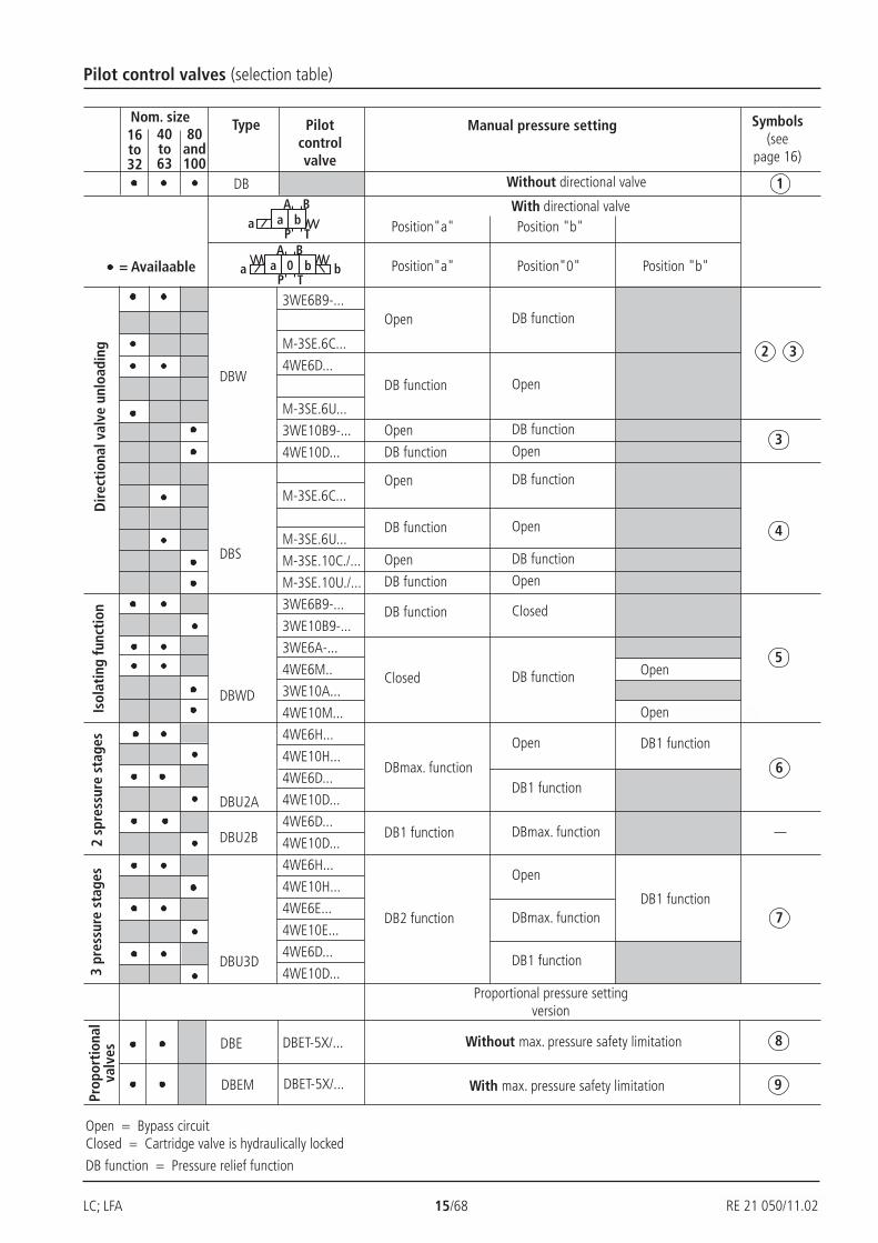
= Availaable
BA
P Ta a b
BA
P Ta b0a b
Pilot control valves (selection table)D
irec
tion
al v
alve
unl
oadi
ng
DBW
DBS
DBWD
DBU2A
DBU2B
DBU3D
3WE6B9-...
M-3SE.6C...
4WE6D...
M-3SE.6U...
3WE10B9-...
4WE10D...
M-3SE.6C...
M-3SE.6U...
M-3SE.10C./...
M-3SE.10U./...
3WE6B9-...
3WE10B9-...
3WE6A-...
4WE6M..
3WE10A...
4WE10M...
4WE6H...
4WE10H...
4WE6D...
4WE10D...
4WE6D...
4WE10D...
4WE6H...
4WE10H...
4WE6E...
4WE10E...
4WE6D...
4WE10D...
Open
DB function
Open
DB function
Open
DB function
Open
DB function
DB function
Closed
Isol
atin
g fu
ncti
on
16to32
40to63
80and100
Nom. size Type Pilotcontrolvalve
Manual pressure setting Symbols(see
page 16)
Position"a" Position "b"
Without directional valve
DB function
Open
DB function
Open
DB function
Open
DB function
Open
Closed
DB function
Open
DB1 function
Open
Open
DB1 function
DB1 function
DBmax. function
Open
DBmax. function
DB1 function
Without max. pressure safety limitation
With max. pressure safety limitation
Proportional pressure settingversion
Open = Bypass circuitClosed = Cartridge valve is hydraulically locked
DB function = Pressure relief function
Prop
orti
onal
valv
es3
pres
sure
sta
ges
2 sp
ress
ure
stag
es
DBmax. function
DB1 function
DB2 function
Position"a" Position"0" Position "b"
DBE
DBEM
DBET-5X/...
DBET-5X/...
With directional valve
1DB
2 3
3
4
5
6
7
8
9
RE 21 050/11.02
RE 21 050/02.99 16/68 LC; LFA
F**X
X
A
YB
X** TP T
A B
D**
F**
X
X
A
Y
Y
B
X**
P**
T
a
P T
A B
D**
F**
X
A
Y
Y
B
a
X
A**
P T
A
F**
X
A
YB
X
P**B
D**Y
F**X
A
Y
Y
B
X**
B**P T
A Ba
X
F**
X
A
YB
D**P**
P T
A Ba
DB max
DB 1
B
A T
P**
F**
X
A
YB
D**P**
P T
A Ba
DB max
DB 1
A T
X**
DB 2
X
A
YB
D**P**
X**YX
X
A
YB
D**P**
X**YX
F**
P T
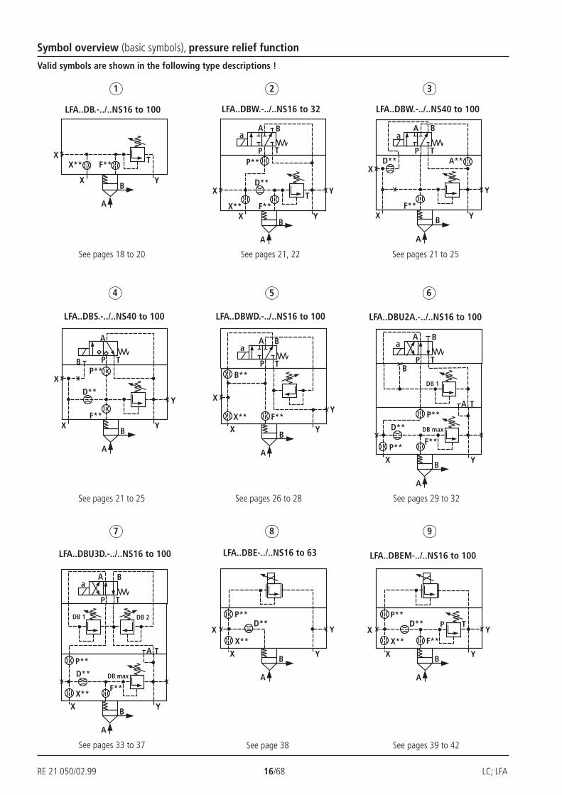
Symbol overview (basic symbols), pressure relief function
Valid symbols are shown in the following type descriptions !
1 2 3
4 5 6
7 8 9
LFA..DB.-../..NS16 to 100 LFA..DBW.-../..NS16 to 32 LFA..DBW.-../..NS40 to 100
LFA..DBS.-../..NS40 to 100 LFA..DBWD.-../..NS16 to 100 LFA..DBU2A.-../..NS16 to 100
LFA..DBU3D.-../..NS16 to 100 LFA..DBE-../..NS16 to 63 LFA..DBEM-../..NS16 to 100
See pages 18 to 20 See pages 21, 22 See pages 21 to 25
See pages 21 to 25 See pages 26 to 28 See pages 29 to 32
See pages 33 to 37 See page 38 See pages 39 to 42
LC; LFA 17/68 RE 21 050/02.99
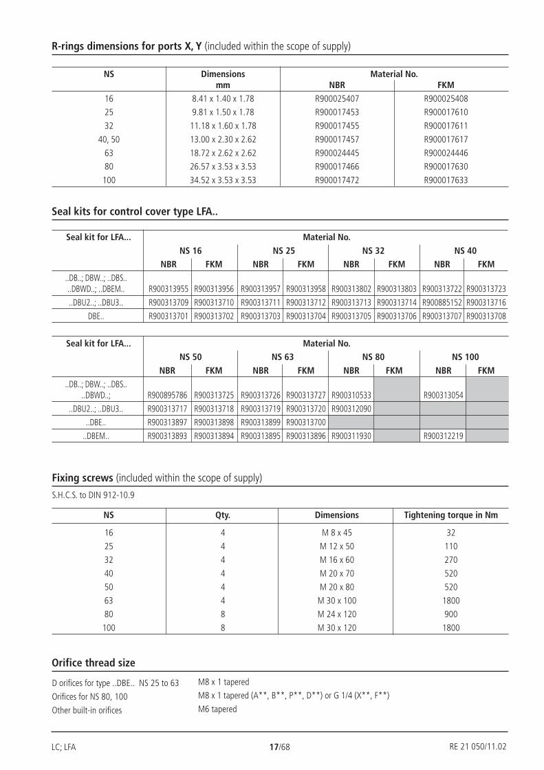
R-rings dimensions for ports X, Y (included within the scope of supply)
NS Dimensions Material No.mm NBR FKM
16 8.41 x 1.40 x 1.78 R900025407 R900025408
25 9.81 x 1.50 x 1.78 R900017453 R900017610
32 11.18 x 1.60 x 1.78 R900017455 R900017611
40, 50 13.00 x 2.30 x 2.62 R900017457 R900017617
63 18.72 x 2.62 x 2.62 R900024445 R900024446
80 26.57 x 3.53 x 3.53 R900017466 R900017630
100 34.52 x 3.53 x 3.53 R900017472 R900017633
Seal kits for control cover type LFA..
Seal kit for LFA... Material No.
NS 16 NS 25 NS 32 NS 40NBR FKM NBR FKM NBR FKM NBR FKM
..DB..; DBW..; ..DBS....DBWD..; ..DBEM.. R900313955 R900313956 R900313957 R900313958 R900313802 R900313803 R900313722 R900313723
..DBU2..; ..DBU3.. R900313709 R900313710 R900313711 R900313712 R900313713 R900313714 R900885152 R900313716
DBE.. R900313701 R900313702 R900313703 R900313704 R900313705 R900313706 R900313707 R900313708
Seal kit for LFA... Material No.NS 50 NS 63 NS 80 NS 100
NBR FKM NBR FKM NBR FKM NBR FKM
..DB..; DBW..; ..DBS....DBWD..; R900895786 R900313725 R900313726 R900313727 R900310533 R900313054
..DBU2..; ..DBU3.. R900313717 R900313718 R900313719 R900313720 R900312090
..DBE.. R900313897 R900313898 R900313899 R900313700
..DBEM.. R900313893 R900313894 R900313895 R900313896 R900311930 R900312219
M8 x 1 tapered
M8 x 1 tapered (A**, B**, P**, D**) or G 1/4 (X**, F**)
M6 tapered
D orifices for type ..DBE.. NS 25 to 63
Orifices for NS 80, 100
Other built-in orifices
Orifice thread size
Fixing screws (included within the scope of supply)
S.H.C.S. to DIN 912-10.9
NS Qty. Dimensions Tightening torque in Nm
16 4 M 8 x 45 32
25 4 M 12 x 50 110
32 4 M 16 x 60 270
40 4 M 20 x 70 520
50 4 M 20 x 80 520
63 4 M 30 x 100 1800
80 8 M 24 x 120 900
100 8 M 30 x 120 1800
RE 21 050/11.02

RE 21 050/02.99 18/68 LC; LFA
F**X
X
A
YB
X** T
D**
Ø 3
2
3
82
91
4252 max
9 43
DBD.2K.
L4
L2
4
G 1
/4 /1
2H
2H
1H
3
D
X F Y
10 SW 22 SW 10104
80 max
2L1
L3
188
6; 71
10 5
H4Ø
35 Ø 4
0
0
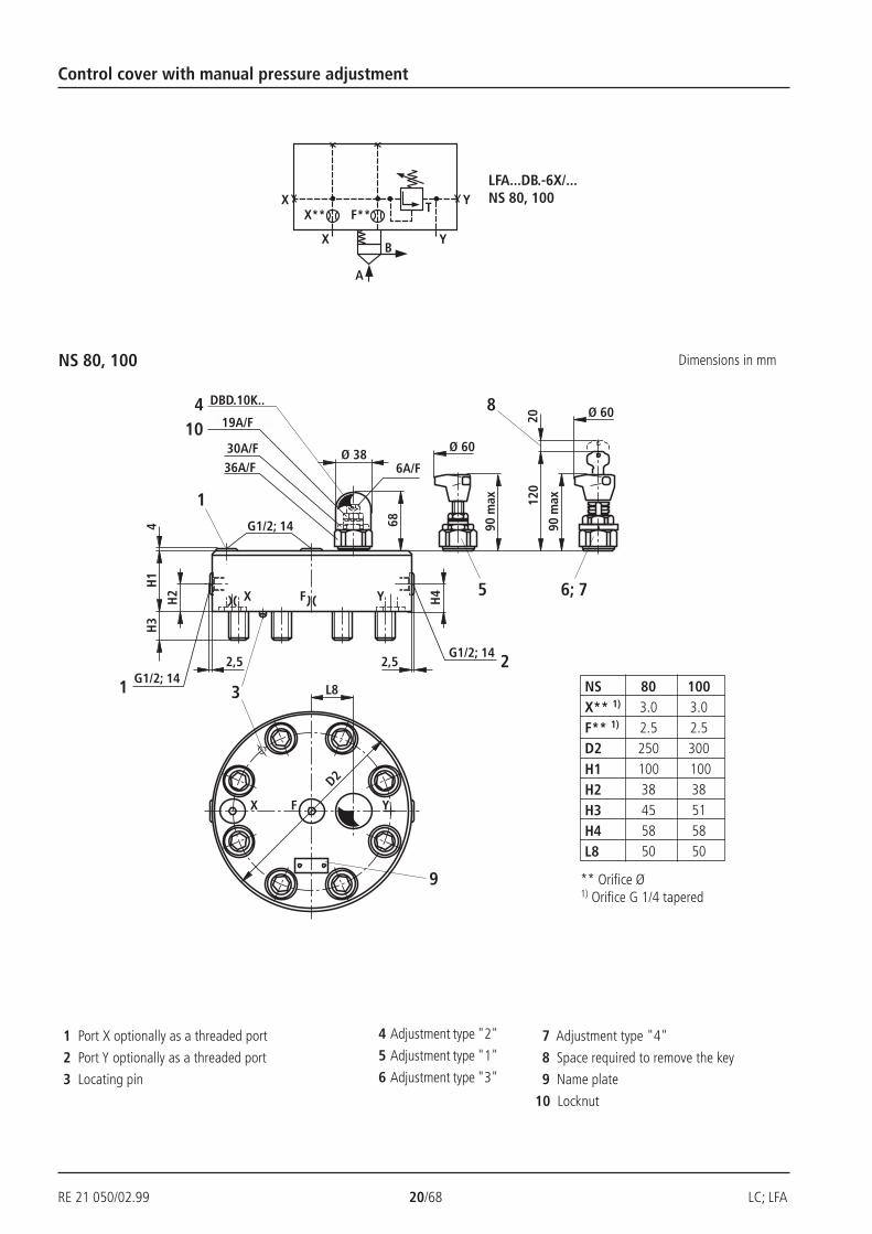
Control cover with manual pressure adjustment
1 2 3 4 5 6 9NS 16 to 100LFA DB
Nom. size 16Nom. size 25Nom. size 32Nom. size 40Nom. size 50Nom. size 63
Nom. size 80Nom. size 100
= 16= 25= 32= 40= 50= 63= 80= 100
Series 7X
Series 6X
Adjustment type
Rotary knob = 1Hexagon with protective cap = 2
Lockable rotary knob with scale = 3(H-key to automotive industry standards)
Rotary knob with scale not lockable = 4
No code = NBR sealsV = FKM seals
(other seals on request)
Attention!The compatibility of the seals and pressure
fluid has to be taken into account!
NS 16, 25 ,32
025 = 25 bar050 = 50 bar100 = 100 bar200 = 200 bar315 = 315 bar420 = 420 bar
NS 40, 50, 63, 80, 100
025 = 25 bar050 = 50 bar100 = 100 bar200 = 200 bar315 = 315 bar400 = 400 bar
Pressure stages
6X = Series 6X (NS 80 and 100)
7X = Series 7X (NS 16 to 63)
NS 16, 25 ,32 LFA..DB.-7X/.. NS 16, 25, 32
With NS 32
With NS 16, 25
Only withversion LFA 32 DB.
1 Port X optionally as threaded port3 Locating pin4 Adjustment type "2"5 Adjustment type "1"
6 Adjustment type "3"7 Adjustment type "4"8 Space required to remove
the key
9 Name plate10 Locknut
NSX**1)
F**1)
D**1)
H1H2H3H4L1L2L3L4
160.81.0
401715196580
36.532.5
250.81.0
40192419858549
45.5
32
1.20.85026282610010056.553
** Orifice Ø1) Orifice M6 tapered
Dimensions in mm
22A/F 10A/F

LC; LFA 19/68 RE 21 050/02.99
SW6
124
SW19
SW30
SW32
10
94 max
204
D1/
T1
H2
H1
H3
Ø 3
5
H4
6; 75
8DBD.6K.. 4
94 max
72
4
D
XF
Y
D1/T1 2
3
X Y
L3L4L5
9
L1
L2
1
Ø 6
0
Ø 6
0
F**X
X
A
YB
T
D**Y
4
G1/
2; 1
4
H2H
1H
3
Ø 35
H4
DBD.6K..
D
XF
Y
3
X Y
90
90
9
L1
4
G1/
2; 1
4
4
94 m
ax
94 m
ax124
208
2
6; 7
Ø 60
Ø 60
5
72
1
SW6SW19
SW30SW3210
LFA..DB.-7X/..NS 40, 50, 63
Control cover with manual pressure adjustment
NS 40, 50
NS 63
1 Port X optionally as a threaded port
2 Port Y optionally as a threaded port
3 Locating pin
4 Adjustment "2"
5 Adjustment "1"
6 Adjustment "3"
7 Adjustment "4"
8 Space required to remove the key
9 Name plate
10 Locknut
NSF** 1)
D** 1)
D1H1H2H3H4 L1L2L3L4L5T1
401.21.0
G1/4602832271256989766012
501.52.0
G1/2 6819.5343514080105847014
632.02.5
823050
45.5180
** Orifice Ø1) Orifice M6 tapered
32A/F
30A/F
19A/F
6A/F
19A/F
32A/F
6A/F
30A/F
RE 21 050/02.99 20/68 LC; LFA
F**X
X
A
YB
T YX**
2,5
H2
H1
H3
Ø 38
5
DBD.10K..
3
9
190
max
90 m
ax120
20
8
2
6; 7
4 68
2,5
L8
YFX
D2
YFX
H4
G1/2; 14
1 G1/2; 14
5
G1/2; 14
SW36SW30
SW19
SW6
104
Ø 60
Ø 60
Control cover with manual pressure adjustment
NS 80, 100
LFA...DB.-6X/...NS 80, 100
1 Port X optionally as a threaded port
2 Port Y optionally as a threaded port
3 Locating pin
4 Adjustment type "2"
5 Adjustment type "1"
6 Adjustment type "3"
7 Adjustment type "4"
8 Space required to remove the key
9 Name plate
10 Locknut
1003.02.5300 10038515850
803.02.525010038455850
NSX** 1)
F** 1)
D2H1H2H3H4L8
** Orifice Ø1) Orifice G 1/4 tapered
Dimensions in mm
19A/F
30A/F36A/F 6A/F
LC; LFA 21/68 RE 21 050/02.99
P T
A Ba
P T
A
P T
A
P T
A
P T
A Ba
P T
A
P T
A
D**
F**
X
X
A
Y
P
Y
T
A B
B
X**
P**
T
a
D**
F**
X
A
Y
P
Y
T
A B
B
a
X
A**
F**
X
A
Y
P T
A
BX
P**B
D**Y
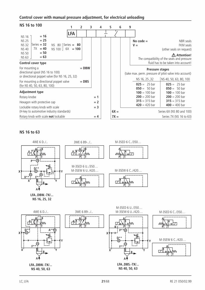
Control cover with manual pressure adjustment, for electrical unloading
1 2 3 4 5 6 9NS 16 to 100
LFANS 16NS 25NS 32NS 40NS 50NS 63
Series7X
= 16= 25= 32= 40= 50= 63
NS 80NS 100
Series6X
= 80= 100
Control cover type
For mounting a = DBWdirectional spool (NS 16 to 100)or directional poppet valve (for NS 16, 25, 32)
For mounting a directional poppet valve = DBS(for NS 40, 50, 63, 80, 100)
Adjustment type
Rotary knobe = 1Hexagon with protective cap = 2
Lockable rotary knob with scale = 3(H-key to automotive industry standards)
Rotary knob with scale not lockable = 4
No code = NBR sealsV = FKM seals
(other seals on request)
Attention!The compatibility of the seals and pressure
fluid has to be taken into account!
NS 16, 25 ,32
025 = 25 bar050 = 50 bar100 = 100 bar200 = 200 bar315 = 315 bar420 = 420 bar
NS 40, 50, 63, 80, 100
025 = 25 bar050 = 50 bar100 = 100 bar200 = 200 bar315 = 315 bar400 = 400 bar
Pressure stages(take max. perm. pressure of pilot valve into account)
6X = Series 6X (NS 80 and 100)
7X = Series 7X (NS 16 to 63)
NS 16 to 63
LFA..DBW.-7X/...NS 16, 25, 32
4WE 6 D../.. 3WE 6 B9-../.. M-3SED 6 C../350…
M-3SEW 6 C../420…M-3SED 6 U../350…M-3SEW 6 U../420…
4WE 6 D../.. 3WE 6 B9-../..M-3SED 6 U../350…M-3SEW 6 U../420… M-3SED 6 C../350…
M-3SEW 6 C../420…
LFA..DBS.-7X/...NS 40, 50, 63
LFA..DBW.-7X/...NS 40, 50, 63
RE 21 050/02.99 22/68 LC; LFA
85 6;7
18
10480 max
Ø 3
2
Ø 4
0
3
21
98
0
SW 10SW 22
4252 max
40,5L5
L6
G 1/4 /12
L2
4
32,5
L34
L12
X
PA
T
BY
L4Ø
35
1042
3 109
H3
H1
H2
G 1
/4 /1
2
D
FX
PA
Y H4
1
DBD.2K
11 A
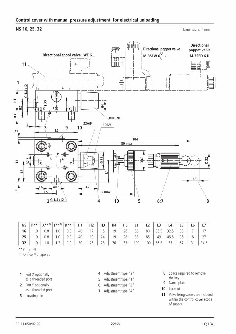
Control cover with manual pressure adjustment, for electrical unloading
NS 16, 25, 32
Directional spool valve . WE 6...
Directional poppet valve
M-3SEW 6 ../…
Directionalpoppet valve
M-3SED 6 U
Dimensions in mm
1 Port X optionallyas a threaded port
2 Port Y optionallyas a threaded port
3 Locating pin
4 Adjustment type "2"
5 Adjustment type "1"
6 Adjustment type "3"
7 Adjustment type "4"
8 Space required to removethe key
9 Name plate
10 Locknut
11 Valve fixing screws are includedwithin the control cover scopeof supply
** Orifice Ø1) Orifice M6 tapered
UC
NS P**1) X**1) F**1) D**1) H1 H2 H3 H4 H5 L1 L2 L3 L4 L5 L6 L716 1.0 0.8 1.0 0.8 40 17 15 19 28 65 80 36.5 32.5 35 7 17
25 1.0 0.8 1.0 0.8 40 19 24 19 28 85 85 49 45.5 36 8 27
32 1.0 1.0 1.2 1.0 50 26 28 26 37 100 100 56.5 53 57 31 34.5
22A/F 10A/F
LC; LFA 23/68 RE 21 050/02.99
32,5
SW32104
H2H
1H
3
H4
6; 75
DBD.6K..
94 max
72
D
XF
Y
3
X Y
L5
L4
L7
2
L1
L3
A
A
B AP
T
94 max
124 20
31
L3*
L6 40,5 9
11
4
1
SW30 SW19
SW6
H5
H2*
D
F
P
X
A
Ø 6
0
Ø 6
0
Ø 3
5
8
D1/T1
D1/T1
D1/
T1
PB
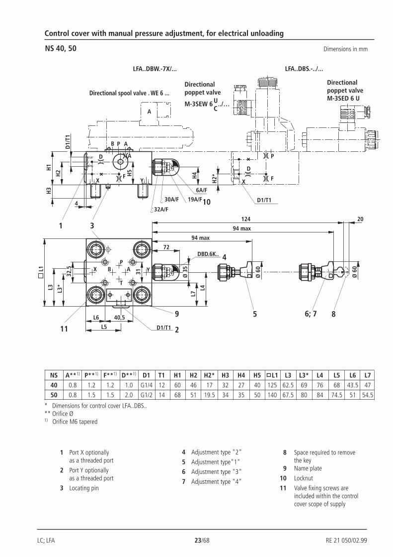
Control cover with manual pressure adjustment, for electrical unloading
NS 40, 50 Dimensions in mm
* Dimensions for control cover LFA..DBS..** Orifice Ø1) Orifice M6 tapered
1 Port X optionallyas a threaded port
2 Port Y optionallyas a threaded port
3 Locating pin
4 Adjustment type "2"
5 Adjustment type"1"
6 Adjustment type "3"
7 Adjustment type "4"
8 Space required to removethe key
9 Name plate
10 Locknut
11 Valve fixing screws areincluded within the controlcover scope of supply
LFA..DBS.-../...LFA..DBW.-7X/...
Directionalpoppet valve
M-3SEW 6 ../…UC
Directionalpoppet valveM-3SED 6 U
Directional spool valve . WE 6 ...
NS A**1) P**1) F**1) D**1) D1 T1 H1 H2 H2* H3 H4 H5 L1 L3 L3* L4 L5 L6 L7
40 0.8 1.2 1.2 1.0 G1/4 12 60 46 17 32 27 40 125 62.5 69 76 68 43.5 47
50 0.8 1.5 1.5 2.0 G1/2 14 68 51 19.5 34 35 50 140 67.5 80 84 74.5 51 54.5
32A/F
30A/F
6A/F
19A/F
RE 21 050/02.99 24/68 LC; LFA
B AP
T
4
G1/
2; 1
4
55
8250
Ø 35
45
DBD.6K..
D
X F Y
3
X Y
90
90
9
180
103
G1/
2; 1
4
4
2
A
40,571
32,5
8731
35
11
72
4
SW19
SW6
10
AB
94 m
ax
94 m
ax124
208
6; 75
SW30
SW32
Ø 60
Ø 60
1
P
F
D
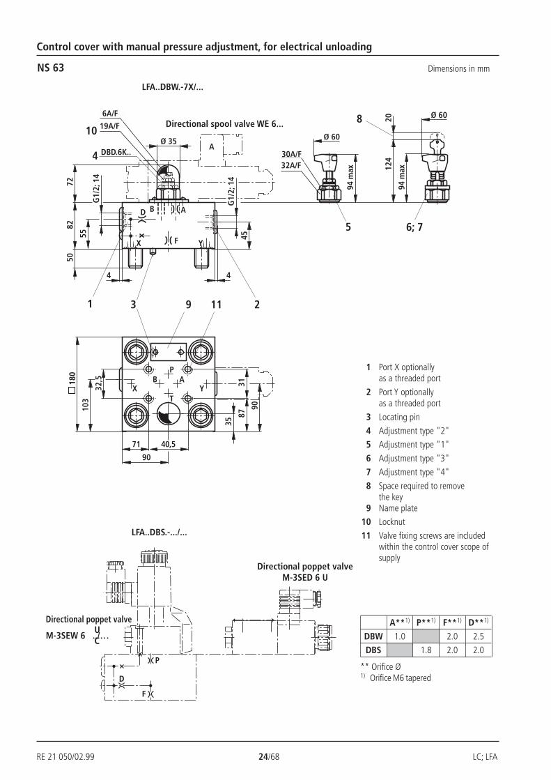
Control cover with manual pressure adjustment, for electrical unloading
NS 63 Dimensions in mm
LFA..DBW.-7X/...
LFA..DBS.-.../...
Directional poppet valveM-3SED 6 U
Directional poppet valve
M-3SEW 6 ../…UC
** Orifice Ø1) Orifice M6 tapered
1 Port X optionallyas a threaded port
2 Port Y optionallyas a threaded port
3 Locating pin
4 Adjustment type "2"
5 Adjustment type "1"
6 Adjustment type "3"
7 Adjustment type "4"
8 Space required to removethe key
9 Name plate
10 Locknut
11 Valve fixing screws are includedwithin the control cover scope ofsupply
Directional spool valve WE 6...
A**1) P**1) F**1) D**1)
DBW 1.0 2.0 2.5
DBS 1.8 2.0 2.0
6A/F
19A/F
30A/F32A/F

LC; LFA 25/68 RE 21 050/02.99
P T
A Ba
P T
A
P T
AaF**
X
A
Y
P T
A
BX
A**
Y
B**
Ba
B A
P
T
2,5
H2
H1
H3
Ø 38
DBD.10K..
3 9
2
68
2,5
YFX
D2Y
F
X
H4
G1/2; 14
1
SW36SW30SW19SW6
10
4
B A
L8
14
31 11
590 m
ax
90 m
ax120
208
6; 75
Ø 60
Ø 60
X
G1/2; 14
A
F**X
A
Y
P T
A
BX
P**
YX**
a
Control cover with manual pressure adjustment, for electrical unloading
NS 80, 100
4WE 10 D...M-3SED 10 U../350…M-3SEW 10 U../420… M-3SED 10 C../350…
M-3SEW 10 C../420…
3WE 10 B9...
LFA..DBS.-6X/...NS 80, 100
LFA..DBW.-6X/...NS 80, 100
Directional poppet valveM-3SED 10 U
Directional poppet valve
M-3SEW 10 ../…UC
8 Space required to removethe key
9 Name plate
10 Locknut
11 Valve fixing screws areincluded within the controlcover scope of supply
1 Port X optionallyas a threaded port
2 Port Y optionallyas a threaded port
3 Locating pin
4 Adjustment type "2"
5 Adjustment type "1"
6 Adjustment type "3"
7 Adjustment type "4"
801.23.03.53.02.525010030455275
1001.53.03.53.02.530010030515285
NSA**1)
B**1)
P**1)
X**2)
F**2)
D2H1H2H3H4L8
** Orifice Ø1) Orifice M8 x 1 tapered2) Orifice G 1/4 tapered
Directional spool valve WE 10...6A/F
19A/F30A/F36A/F
RE 21 050/02.99 26/68 LC; LFA
P T
A Ba
P T
A Ba b
P T
A Ba
P T
A Ba b
F**X
A
Y
Y
B
X**
B**P T
A Ba
F**X
A
Y
Y
B
X**
B**P T
A Ba
X
F**X
A
Y
Y
B
B**P T
A Ba
XD**
F**X
A
Y
Y
B
X**
B**P T
A Ba
X
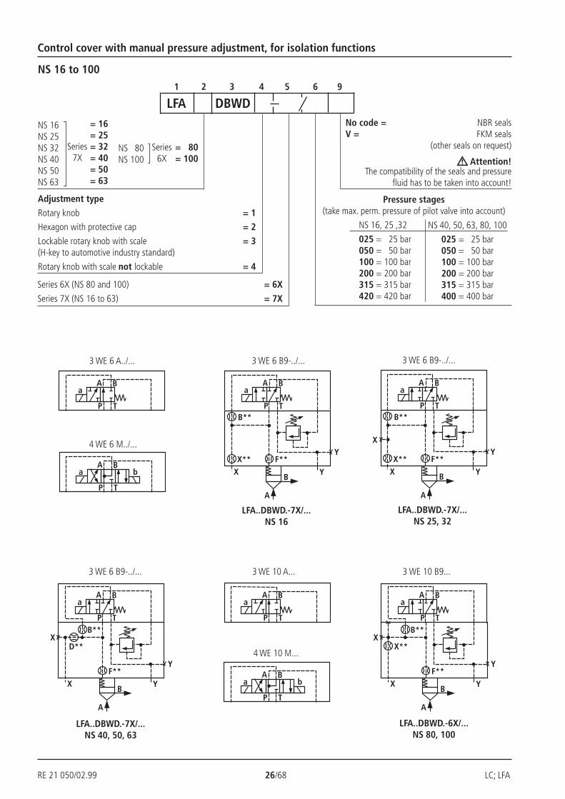
Control cover with manual pressure adjustment, for isolation functions
1 2 3 4 5 6 9
NS 16 to 100
LFA DBWD
NS 16NS 25NS 32NS 40NS 50NS 63
Series7X
= 16= 25= 32= 40= 50= 63
NS 80NS 100
Series6X
= 80= 100
No code = NBR sealsV = FKM seals
(other seals on request)
Attention!The compatibility of the seals and pressure
fluid has to be taken into account!
NS 16, 25 ,32
025 = 25 bar050 = 50 bar100 = 100 bar200 = 200 bar315 = 315 bar420 = 420 bar
NS 40, 50, 63, 80, 100
025 = 25 bar050 = 50 bar100 = 100 bar200 = 200 bar315 = 315 bar400 = 400 bar
Pressure stages(take max. perm. pressure of pilot valve into account)
Adjustment type
Rotary knob = 1Hexagon with protective cap = 2
Lockable rotary knob with scale = 3(H-key to automotive industry standard)
Rotary knob with scale not lockable = 4
Series 6X (NS 80 and 100) = 6X
Series 7X (NS 16 to 63) = 7X
3 WE 6 A../...
4 WE 6 M../...
3 WE 6 B9-../...
LFA..DBWD.-7X/...NS 25, 32
LFA..DBWD.-7X/...NS 16
LFA..DBWD.-6X/...NS 80, 100
LFA..DBWD.-7X/...NS 40, 50, 63
4 WE 10 M...
3 WE 6 B9-../... 3 WE 10 A... 3 WE 10 B9...
3 WE 6 B9-../...
LC; LFA 27/68 RE 21 050/02.99
Ø 3
2
3
82
90
1
4252 max
9 43 DBD.2K.
4
G 1
/4; 1
2H
2H
1H
3
X F Y
10SW22
SW10
10480 max
18
86; 7
1
Ø 4
0
10 5H
4Ø35
L22L1
L3
ABP
TYX
40,5L6L5
32,5
4
G 1/4; 12
L4
31L7
BA
H5
11 A
2
32,5
SW610
4
D1/
T1
H2H
1H
3
Ø 3
5
H4
DBD.6K..
72
D
X F Y
3
XY
L5
L4
L7
L1
L3
1
AP
A
B AP
T
31
L6 40,59
4
H5
B
SW19
SW30
SW32
4
D1/T12
11
5
Ø 6
0
94 max
6; 7124 20
Ø 6
0
94 max
8
Control cover with manual pressure adjustment, for isolation functions
NS 16, 25, 32 Dimensions in mm
Directional spool valve . WE 6...
NS 40, 50
Directional spool valve . WE 6...
For dimension table see page 28
1 Port X optionally as athreaded port
2 Port Y optionally as athreaded port
3 Locating pin
4 Adjustment type "2"
5 Adjustment type "1"
6 Adjustment type "3"
7 Adjustment type "4"
8 Space required to removethe key
9 Name plate
10 Locknut
11 Valve fixing screws are included withinthe control cover scope of supply
22A/F
10A/F
32A/F
30A/F
19A/F
6A/F
RE 21 050/02.99 28/68 LC; LFA
G1/
2; 1
4
B AP
T
4
G1/
2; 1
4
H2H
1H
3
Ø 35
H4
DBD.6K..
D
X F Y
3
X Y
90
90
9
L1
103
1
4
2
A
40,571
32,5
8731
35
72
4; 5…711
AB
BA
P
T
2,5
H2
H1
H3
Ø 38
DBD.10K..
3 9 2
68
2,5
YFX
D2YX
H4
G1/2; 14
1 G1/2; 14
SW36SW30SW19SW6
10
4
B
L8
14
41
11
90 m
ax
5
90 m
ax
120
208
6; 7X
Ø 60
Ø 60
Control cover with manual pressure adjustment, for isolation functions
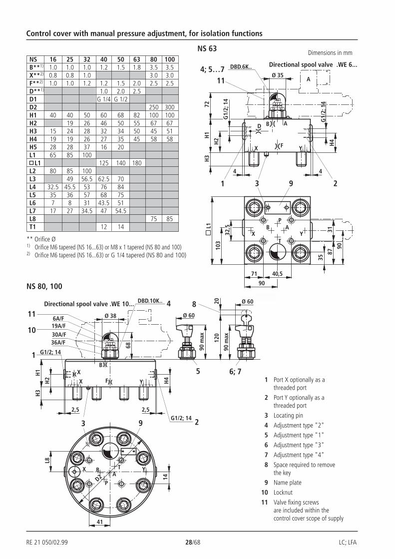
NS 63 Dimensions in mm
** Orifice Ø1) Orifice M6 tapered (NS 16...63) or M8 x 1 tapered (NS 80 and 100)2) Orifice M6 tapered (NS 16...63) or G 1/4 tapered (NS 80 and 100)
NS 16 25 32 40 50 63 80 100B**1) 1.0 1.0 1.0 1.2 1.5 1.8 3.5 3.5X**2) 0.8 0.8 1.0 3.0 3.0F**2) 1.0 1.0 1.2 1.2 1.5 2.0 2.5 2.5D**1) 1.0 2.0 2.5D1 G 1/4 G 1/2D2 250 300H1 40 40 50 60 68 82 100 100H2 19 26 46 50 55 67 67H3 15 24 28 32 34 50 45 51H4 19 19 26 27 35 45 58 58H5 28 28 37 16 20L1 65 85 100 L1 125 140 180L2 80 85 100L3 49 56.5 62.5 70L4 32.5 45.5 53 76 84L5 35 36 57 68 75L6 7 8 31 43.5 51L7 17 27 34.5 47 54.5L8 75 85T1 12 14
NS 80, 100
Directional spool valve .WE 6...
Directional spool valve .WE 10...
1 Port X optionally as athreaded port
2 Port Y optionally as athreaded port
3 Locating pin
4 Adjustment type "2"
5 Adjustment type "1"
6 Adjustment type "3"
7 Adjustment type "4"
8 Space required to removethe key
9 Name plate
10 Locknut
11 Valve fixing screwsare included within thecontrol cover scope of supply
6A/F19A/F30A/F36A/F
LC; LFA 29/68 RE 21 050/02.99
P T
A Ba b
P T
A Ba b
P T
A Ba b
F**
X
A
YB
D**P**
P T
A Ba
DB max
DB 1
B
A T
X**YX
F**
X
A
YB
D**P**
P T
A Ba
DB max
DB 1
A
A T
X**YX
F**X
A
Y
Y
B
D**P**
P T
A Ba
XDB max
DB 1
B
B A T
F**X
A
Y
Y
B
D**P**
P T
A Ba
XDB max
DB 1
A
B A T
F**
X
A
Y
Y
B
D**
P**
P T
A Ba
XDB max
DB 1
B
B A T
F**
X
A
Y
Y
B
D**
P**
P T
A Ba
XDB max
DB 1
A
B A T
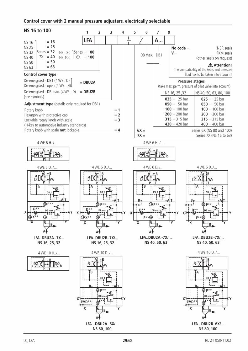
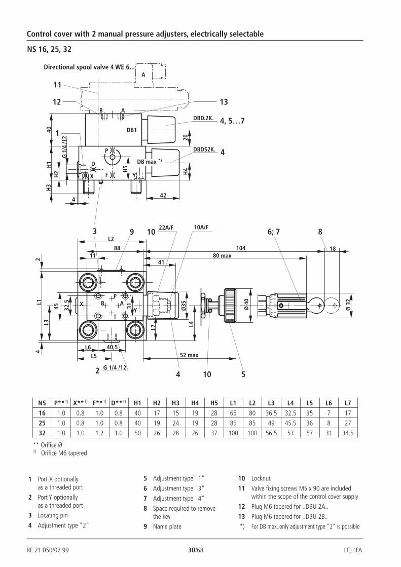
Control cover with 2 manual pressure adjusters, electrically selectable
1 2 3 4 5 6 7 9NS 16 to 100
DB1DB max.
No code = NBR sealsV = FKM seals
(other seals on request)
Attention!The compatibility of the seals and pressure
fluid has to be taken into account!
NS 16, 25 ,32
025 = 25 bar050 = 50 bar100 = 100 bar200 = 200 bar315 = 315 bar420 = 420 bar
NS 40, 50, 63, 80, 100
025 = 25 bar050 = 50 bar100 = 100 bar200 = 200 bar315 = 315 bar400 = 400 bar
Pressure stages (take max. perm. pressure of pilot valve into account)
6X = Series 6X (NS 80 and 100)7X = Series 7X (NS 16 to 63)
LFA A...NS 16NS 25NS 32NS 40NS 50NS 63
Series7X
= 16= 25= 32= 40= 50= 63
NS 80NS 100
Series6X
= 80= 100
Adjustment type (details only required for DB1)
Rotary knob = 1Hexagon with protective cap = 2Lockable rotary knob with scale = 3(H-key to automotive industry standards)Rotary knob with scale not lockable = 4
Control cover typeDe-energised - DB1 (4 WE.. D)De-energised - open (4 WE.. H)
De-energised - DB max. (4 WE.. D) = DBU2B(see symbols)
= DBU2A
LFA..DBU2A.-7X...NS 16, 25, 32
LFA...DBU2B.-6X/...NS 80, 100
LFA...DBU2A.-6X/...NS 80, 100
LFA..DBU2B.-7X/...NS 40, 50, 63
LFA..DBU2A.-7X/...NS 40, 50, 63
LFA..DBU2B.-7X/...NS 16, 25, 32
4 WE 10 D../...4 WE 10 H../...
4 WE 6 H../...
4 WE 6 D../...
4 WE 6 H../...
4 WE 6 D../...
4 WE 10 D../...
4 WE 6 D../... 4 WE 6 D../...
RE 21 050/11.02
RE 21 050/02.99 30/68 LC; LFA
Ø 3
2
3
82
90
1
41
52 max
9
4
3
DBDS2K.
H4
L2
4
G 1
/4 /1
2H
2H
1H
3
D
X F Y
12
SW 22 SW 10
10480 max2
L1L3
18
86; 7
1
Ø 4
0
10 5
L4Ø
35
P
H5
ABP
TY
X
10
40,5L6L5
45
4
A
2 G 1/4 /12
AB
DB1
13
4
DBD.2K. 4, 5…7
20
40
32,5
8811
31
42
L7
11
DB max *)
Control cover with 2 manual pressure adjusters, electrically selectable
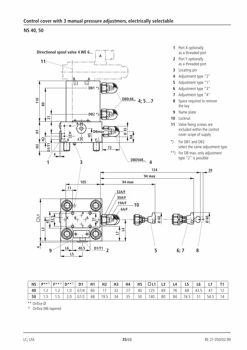
NS 16, 25, 32
Directional spool valve 4 WE 6...
** Orifice Ø1) Orifice M6 tapered
1 Port X optionallyas a threaded port
2 Port Y optionallyas a threaded port
3 Locating pin
4 Adjustment type "2"
5 Adjustment type "1"
6 Adjustment type "3"
7 Adjustment type "4"
8 Space required to removethe key
9 Name plate
10 Locknut
11 Valve fixing screws M5 x 90 are includedwithin the scope of the control cover supply
12 Plug M6 tapered for ..DBU 2A..
13 Plug M6 tapered for ..DBU 2B..
*) For DB max. only adjustment type "2" is possible
NS P**1) X**1) F**1) D**1) H1 H2 H3 H4 H5 L1 L2 L3 L4 L5 L6 L7
16 1.0 0.8 1.0 0.8 40 17 15 19 28 65 80 36.5 32.5 35 7 17
25 1.0 0.8 1.0 0.8 40 19 24 19 28 85 85 49 45.5 36 8 27
32 1.0 1.0 1.2 1.0 50 26 28 26 37 100 100 56.5 53 57 31 34.5
22A/F 10A/F
LC; LFA 31/68 RE 21 050/02.99
32,5
SW610
4
D1/
T1H
2H
1H
3
Ø 3
5
H4
DBDS6K..
72
D
X F Y
3
XY
L5
L4
L7
L1
L3
11
A
P
B
A
B AP
T
31
L6 40,5
9
4
H5
SW19
SW30
SW32
4
D1/T1 2
45
105
11
DBD.6K.. 4, 5…7
1
40
12
13
DB1
DBmax*)20
A
32,5
SW610
4
H2H
1H
3
H4D
X F Y
3
XY
9090
87
L1
103
11
A
P
B
B AP
T31
71 40,5
9
SW19
SW30
SW32
45105
11
DBD.6K..4, 5…7
140
12
13
DB1
20DBm
ax*)
4
G1/2; 14
2G1/2; 14
35
4
Ø 35
5
6; 7
8DBDS6K..
Ø 6
094 max
124 20Ø
60
94 max
72
Control cover with 2 manual pressure adjusters, electrically selectable
NS 40, 50 NS 63
8 Space required to removethe key
9 Name plate
10 Locknut
11 Valve fixing screws M5 x 90are included within the controlcover scope
12 Plug M6 tapered for ..DBU 2A..
13 Plug M6 tapered for ..DBU 2B..
*) For DB max. only adjustment type "2" is possible
1 Port X optionallyas a threaded port
2 Port Y optionallyas a threaded port
3 Locating pin
4 Adjustment type "2"
5 Adjustment type "1"
6 Adjustment type "3"
7 Adjustment type "4"
** Orifice Ø1) Orifice M6 tapered
Directional spool valve 4 WE 6... Directional spool valve 4 WE 6...
NS P**1) F**1) D**1) D1 H1 H2 H3 H4 H5 L1 L3 L4 L5 L6 L7 T1
40 1.2 1.2 1.0 G1/4 60 17 32 27 40 125 69 76 68 43.5 47 12
50 1.5 1.5 2.0 G1/2 68 19.5 34 35 50 140 80 84 74.5 51 54.5 14
63 2.5 2.0 2.5 82 55 50 45 180
32A/F
30A/F
19A/F
6A/F
32A/F
30A/F
19A/F
6A/F
RE 21 050/02.99 32/68 LC; LFA
B AP
T
2,5
H2
H1
H3
DBDS10K..
3
22,5
YFX
D2
Y
F
X
H4
G1/2; 14
1 G1/2; 14
4
A
46
14
31
11
6; 75
90 max
68
90 max
120 20
8
P
70
35
X
14
Ø 3
8
129
13
54
L8
70
*)DBmax
DBD.10K.. 4, 5…7
DB1
Ø 6
0
Ø 6
0
110
SW36
SW30
SW19
SW6
10
A
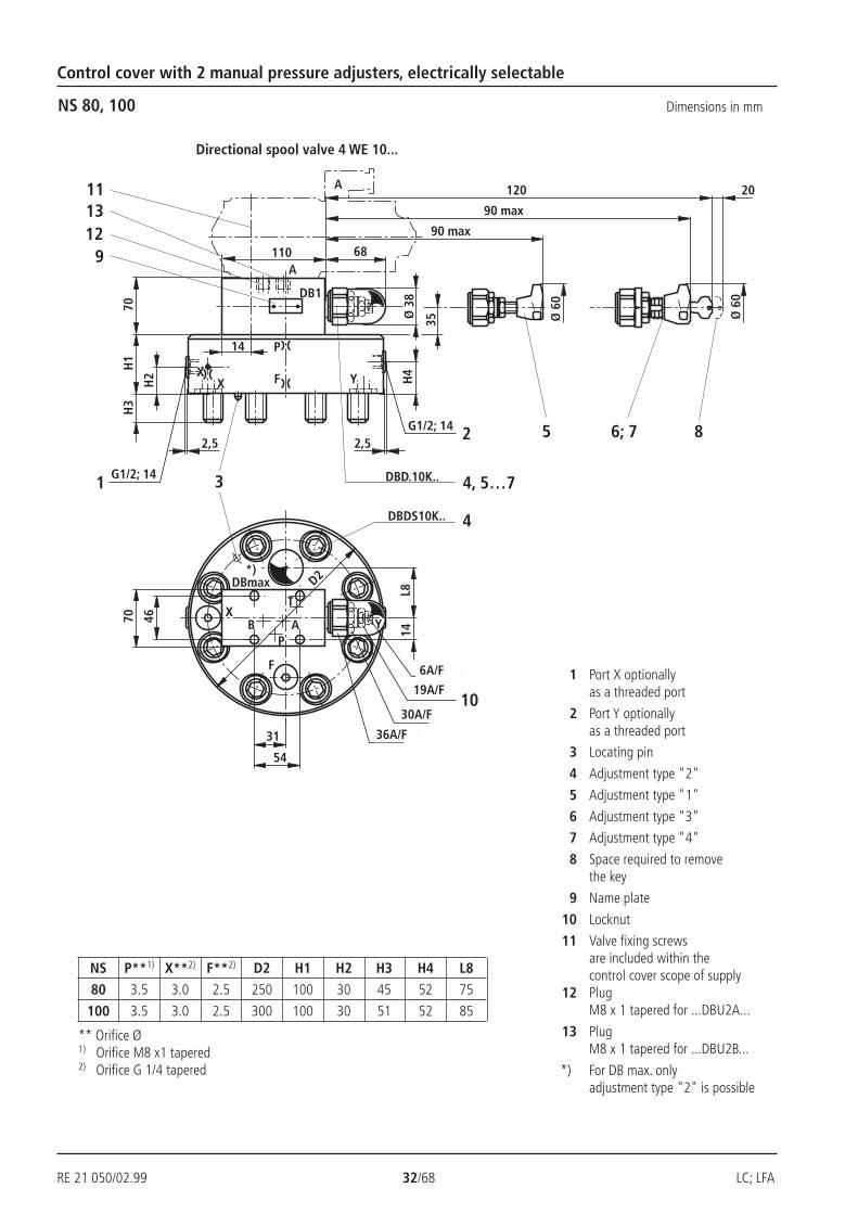
Control cover with 2 manual pressure adjusters, electrically selectable
NS 80, 100 Dimensions in mm
** Orifice Ø1) Orifice M8 x1 tapered2) Orifice G 1/4 tapered
1 Port X optionallyas a threaded port
2 Port Y optionallyas a threaded port
3 Locating pin
4 Adjustment type "2"
5 Adjustment type "1"
6 Adjustment type "3"
7 Adjustment type "4"
8 Space required to removethe key
9 Name plate
10 Locknut
11 Valve fixing screwsare included within thecontrol cover scope of supply
12 PlugM8 x 1 tapered for ...DBU2A...
13 PlugM8 x 1 tapered for ...DBU2B...
*) For DB max. onlyadjustment type "2" is possible
Directional spool valve 4 WE 10...
NS P**1) X**2) F**2) D2 H1 H2 H3 H4 L8
80 3.5 3.0 2.5 250 100 30 45 52 75
100 3.5 3.0 2.5 300 100 30 51 52 85
6A/F
19A/F
30A/F
36A/F

LC; LFA 33/68 RE 21 050/02.99
P T
A B
a b
P T
A B
a b
P T
A B
a b
P T
A B
a b
P T
A B
a b
P T
A B
a b
F**
X
A
YB
D**P**
P T
A Ba
DB max
DB 1
A T
X**
DB 2
YX
P T
A Ba
DB 1
A T
DB 2
F**X
A
Y
Y
B
D**
P**
XDB max
B
P T
A Ba
DB 1 DB 2
F**
X
A
Y
Y
B
D**
P**
XDB max
B A T
Nom. size 16Nom. size 25Nom. size 32Nom. size 40Nom. size 50Nom. size 63
Nom. size 80Nom. size 100
= 16= 25= 32= 40= 50= 63
= 80= 100
Series 7X
Series 6X
Adjustment type (details only for DB1or DB2)*)
Rotary knob = 1Hexagon with protective cap = 2Lockable rotary knob with scale = 3(H-key to automotive industry standards)Rotary knob with scale not lockable = 4
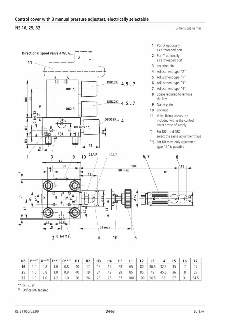
Control cover with 3 manual manual pressure adjusters, electrically selectable
1 2 3 4 5 6 7 8 9
NS 16 to 100
No code = NBR sealsV = FKM seals
(other seals on request)
Attention!The compatibility of the seals and pressure
fluid has to be taken into account!
NS 16, 25 ,32
025 = 25 bar050 = 50 bar100 = 100 bar200 = 200 bar315 = 315 bar420 = 420 bar
NS 40, 50, 63, 80, 100
025 = 25 bar050 = 50 bar100 = 100 bar200 = 200 bar315 = 315 bar400 = 400 bar
Pressure stages(take max. perm. pressure of pilot valve into account)
LFA DBU3D A... B...
DB2
DB1
DBmax
Series 6X (NS 80 and 100) = 6XSeries 7X (NS 16 to 63) = 7X
*) For DB1 and DB2 select the same adjustment type
4WE 6 H .. /...
4WE 6 E .. /...
4WE 6 D .. /...
4WE 10 H.. /...
4WE 10 E.. /...
4WE 10 D.. /...
LFA..DBU3D.-7X/...NS 16, 25, 32
LFA..DBU3D.-7X/...NS 40, 50, 63
LFA...DBU3D.-6X/...NS 80, 100
4WE 6 H .. /...
4WE 6 E .. /...
4WE 6 D .. /...
RE 21 050/02.99 34/68 LC; LFA
Ø 3
2
3
82
90
1
41
52 max
9
4
3
DBDS2K...
H4
L2
4
G 1
/4 /1
2H
2H
1H
3
D
X F Y
SW 22 SW 10
10480 max
2L1
L3
18
86; 71
Ø 4
0
10 5
L4Ø
35
P
H5
ABP
TY
X
10
40,5L6L5
45
4
A
2 G 1/4 /12
AB
DB1 *)
DB max **)
4
DBD.2K. 4, 5…7
100
32,5
8811
31
42
L7
DBD.2K. 4, 5…7DB2 *)
79
21
11
Control cover with 3 manual pressure adjusters, electrically selectable
NS 16, 25, 32 Dimensions in mm
** Orifice Ø1) Orifice M6 tapered
Directional spool valve 4 WE 6...
1 Port X optionallyas a threaded port
2 Port Y optionallyas a threaded port
3 Locating pin
4 Adjustment type "2"
5 Adjustment type "1"
6 Adjustment type "3"
7 Adjustment type "4"
8 Space required to removethe key
9 Name plate
10 Locknut
11 Valve fixing screws areincluded within the controlcover scope of supply
*) For DB1 and DB2select the same adjustment type
**) For DB max. only adjustmenttype "2" is possible
NS P**1) X**1) F**1) D**1) H1 H2 H3 H4 H5 L1 L2 L3 L4 L5 L6 L716 1.0 0.8 1.0 0.8 40 17 15 19 28 65 80 36.5 32.5 35 7 17
25 1.0 0.8 1.0 0.8 40 19 24 19 28 85 85 49 45.5 36 8 27
32 1.0 1.0 1.2 1.0 50 26 28 26 37 100 100 56.5 53 57 31 34.5
22A/F 10A/F
LC; LFA 35/68 RE 21 050/02.99
4
D1/
T1
H2
H1
H3
Ø 3
5
H4
DBDS6K..
72
D
X F Y
3
11
A
P
B
A
4
H5
DBD.6K.. 4; 5…7
1
110
DB2 *)
DBmax**)
DB1 *)
21
89
32,5
SW610
XY
L5
L4
L7
L1
L3
B AP
T
31
L6 40,59
SW19
SW30
SW32
4 D1/T1 2
45
105
11
6; 75
94 max
94 max
124 20
8
Ø 6
0
Ø 6
0
Control cover with 3 manual pressure adjustmers, electrically selectable
NS 40, 50
Directional spool valve 4 WE 6...1 Port X optionally
as a threaded port
2 Port Y optionallyas a threaded port
3 Locating pin
4 Adjustment type "2"
5 Adjustment type "1"
6 Adjustment type "3"
7 Adjustment type "4"
8 Space required to removethe key
9 Name plate
10 Locknut
11 Valve fixing screws areincluded within the controlcover scope of supply
*) For DB1 and DB2select the same adjustment type
**) For DB max. only adjustmenttype "2" is possible
** Orifice Ø1) Orifice M6 tapered
NS P**1) F**1) D**1) D1 H1 H2 H3 H4 H5 L1 L3 L4 L5 L6 L7 T1
40 1.2 1.2 1.0 G1/4 60 17 32 27 40 125 69 76 68 43.5 47 12
50 1.5 1.5 2.0 G1/2 68 19.5 34 35 50 140 80 84 74.5 51 54.5 14
32A/F
30A/F19A/F
6A/F
RE 21 050/02.99 36/68 LC; LFA
32,5
SW610
4
G 1
/2; 1
455
8250
Ø 3
5
45,
72
D
X F Y
3
XY
90
90
87
180
103
11
A
P
B
A
B AP
T
31
71 40,5
SW19
SW30
SW32
45
105
11
DBD.6K.. 4; 5…7
1
110
DB2 *)
94 max
94 max
124 20
DB1 *)
21
89
DBm
ax**
)
G1/
2; 1
4
4
2
DBD.6K.. 4; 5…7
DBDS6K.. 4
35
9
6; 75 8
Ø 6
0
Ø 6
0
Control cover with 3 manual pressure adjusters, electrically selectable
NS 63 Dimensions in mm
Directional spool valve 4 WE 6...
** Orifice Ø1) Orifice M6 tapered
NS
P**1)
F**1)
D**1)
63
2.5
2.0
2.5
1 Port X optionallyas a threaded port
2 Port Y optionallyas a threaded port
3 Locating pin
4 Adjustment type "2"
5 Adjustment type "1"
6 Adjustment type "3"
7 Adjustment type "4"
8 Space required to removethe key
9 Name plate
10 Locknut
11 Valve fixing screws areincluded within the controlcover scope of supply
*) For DB1 and DB2select the same adjustment type
**) For DB max. only adjustment type"2" is possible
32A/F30A/F
19A/F
6A/F
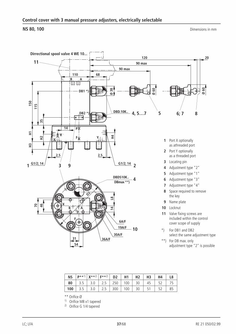
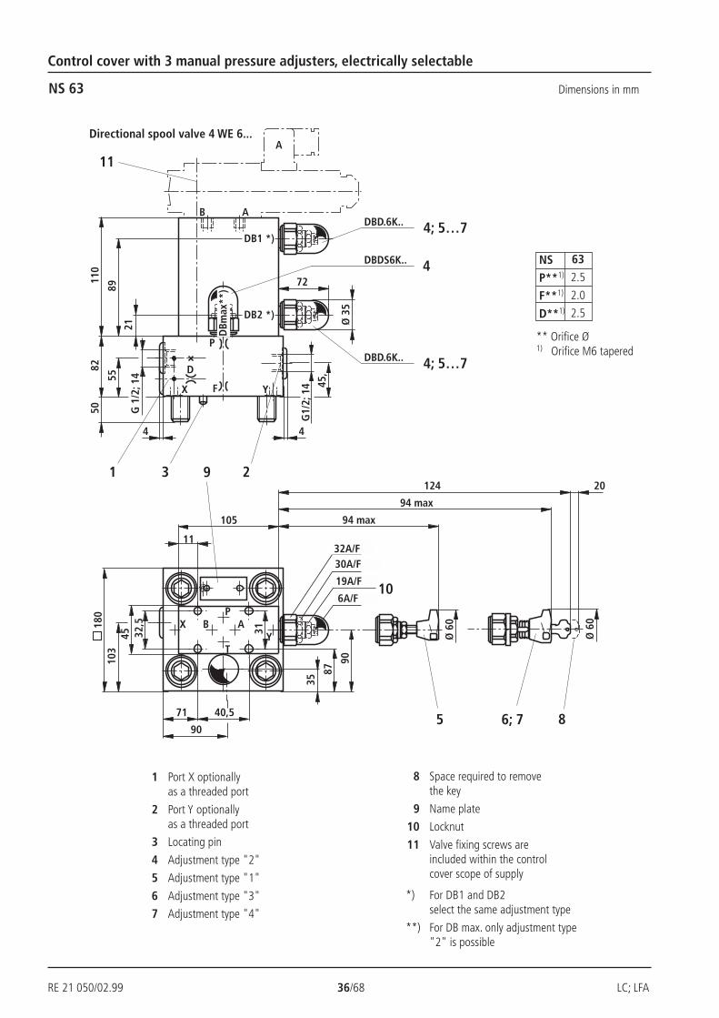
LC; LFA 37/68 RE 21 050/02.99
B AP
T
2,5
H2
H1
H3
DBDS10K..
3 2
2,5
YFX
D2
Y
F
X
H4
G1/2; 141 G1/2; 14
4
B A
46
14
31
1190 max
68
90 max
120 20
P
150
35
X
14
Ø 3
8
54
L8
70
DBmax **)
DBD.10K.. 4, 5…7
115
9
DB2 *)
DB1 *)
SW6
SW19
SW30SW36
110
10
5
Ø 6
0
6; 7 8
Ø 6
0
Control cover with 3 manual pressure adjusters, electrically selectable
NS 80, 100 Dimensions in mm
** Orifice Ø1) Orifice M8 x1 tapered2) Orifice G 1/4 tapered
1 Port X optionallyas athreaded port
2 Port Y optionallyas a threaded port
3 Locating pin
4 Adjustment type "2"
5 Adjustment type "1"
6 Adjustment type "3"
7 Adjustment type "4"
8 Space required to removethe key
9 Name plate
10 Locknut
11 Valve fixing screws areincluded within the controlcover scope of supply
*) For DB1 and DB2select the same adjustment type
**) For DB max. onlyadjustment type "2" is possible
Dirrectional spool valve 4 WE 10...
NS P**1) X**2) F**2) D2 H1 H2 H3 H4 L8
80 3.5 3.0 2.5 250 100 30 45 52 75
100 3.5 3.0 2.5 300 100 30 51 52 85
6A/F
19A/F
30A/F36A/F
RE 21 050/02.99 38/68 LC; LFA
–
32,5
4
D1/
T1
H2
H1
H3 D
1/T1 H
4
D
XF
Y
3
XY
L4
L6
9
L1
L3
1
P
B AP
T
31
L5 40,5 NG 40, 50, 63
4
11 14
9NG 16, 25, 32L2
2
2
X
A
YB
D**P**
X**YX
14
X
A
YB
D** P**
F**YX
14
X
A
YB
D**
B**
F**YX
14
B1**
D1/
T1
H2
H1
H3 D1/
T1
H4
D
X F Y
1
50
146
L5
39,515
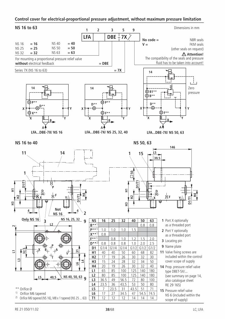
Control cover for electrical-proportional pressure adjustment, without maximum pressure limitation
1 2 3 5 9NS 16 to 63
LFA DBE 7XNS 16NS 25NS 32
= 16= 25= 32
NS 40NS 50NS 63
= 40= 50= 63
No code = NBR sealsV = FKM seals
(other seals on request) Attention!
The compatibility of the seals and pressurefluid has to be taken into account!
Series 7X (NS 16 to 63) = 7X
For mounting a proportional pressure relief valvewithout electrical feedback = DBE
LFA...DBE-7X/ NS 50, 63LFA...DBE-7X/ NS 25, 32, 40LFA...DBE-7X/ NS 16
NS 16 to 40 NS 50, 63
Zeropressure
** Orifice Ø1) Orifice M6 tapered2) Orifice M6 tapered (NS 16), M8 x 1 tapered (NS 25 ... 63)
NS 16 25 32 40 50 63B**1) 0.8 0.8P**1) 1.0 1.0 1.0 1.5X**1) 0.8F**1) 0.8 1.0 1.2 1.5 2.0D**2) 0.8 0.8 0.8 1.0 2.0 2.5D1 G1/4 G1/4 G1/4 G1/2 G1/2 G1/2H1 40 40 50 60 68 82H2 17 19 26 30 32 30H3 15 24 28 32 34 50H4 20 19 26 30 32 40L1 65 85 100 125 140 180L2 80 85 100 125 140 180L3 36.5 49 56.5 72 80 100L4 23.5 36 43,5 53 50 80L5 7 23.5 31 43.5 51 71L6 17 27 34.5 47 54.5 74.5T1 12 12 12 14 14 14
1 Port X optionallyas a threaded port
2 Port Y optionallyas a threaded port
3 Locating pin
9 Name plate
11 Valve fixing screws areincluded within the controlcover scope of supply
14 Prop. pressure relief valvetype DBET-5X/...(see summary on page 14,also catalogue sheetRE 29 165)
15 Pressure relief valveNS 6 (included within thescope of supply)
NotNS 16
Only NS 16
Dimensions in mm
RE 21 050/11.02
NS 16, 25, 32
NS 40, 50, 63
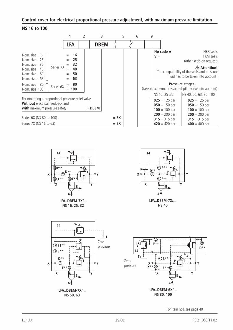
LC; LFA 39/68 RE 21 050/02.99
X
A
YB
D**P**
X**YX
14
F**
P T
14
X
A
YB
D**P**
YXF**
P T
B**
B1**
14
X
A
YB
D**YX
F**
P T
P**
14
X
A
YB
X**YX
F**
P TB**
T TAP
D**
Control cover for electrical-proportional pressure adjustment, with maximum pressure limitation
NS 16 to 100
Nom. size 16Nom. size 25Nom. size 32Nom. size 40Nom. size 50Nom. size 63
Nom. size 80Nom. size 100
= 16= 25= 32= 40= 50= 63
= 80= 100
Series 7X
Series 6X
1 2 3 5 6 9
No code = NBR sealsV = FKM seals
(other seals on request)
Attention!The compatibility of the seals and pressure
fluid has to be taken into account!
NS 16, 25 ,32
025 = 25 bar050 = 50 bar100 = 100 bar200 = 200 bar315 = 315 bar420 = 420 bar
NS 40, 50, 63, 80, 100
025 = 25 bar050 = 50 bar100 = 100 bar200 = 200 bar315 = 315 bar400 = 400 bar
Pressure stages(take max. perm. pressure of pilot valve into account)
LFA DBEM
Series 6X (NS 80 to 100) = 6X
Series 7X (NS 16 to 63) = 7X
For mounting a proportional pressure relief valveWithout electrical feedback andwith maximum pressure safety = DBEM
LFA..DBEM-7X/...NS 50, 63
LFA..DBEM-7X/...NS 40
LFA..DBEM-7X/...NS 16, 25, 32
LFA..DBEM-6X/...NS 80, 100
Zeropressure
Zeropressure
For item nos. see page 40
RE 21 050/11.02

RE 21 050/02.99 40/68 LC; LFA
32,5
4
G1/
4; 1
2
H2
H1
H3
H4
D
XF
Y
3
XY
L4
L6
L1
L3
1
P
B AP
T
31
L5 40,5
11 14
9
L2
42
Ø 3
5
L7 2G1/4; 12
H5
DBDS2K.. 4
SW10
SW22 10
2NS 16, 25, 32 Dimensions in mm
Control cover for electrical-proportional pressure adjustment, with maximum pressure limitation
** Orifice Ø1) Orifice M6 tapered
Ports T and Y - zero pressure
1 Port X optionallyas a threaded port
2 Port Y optionallyas a threaded port
3 Locating pin
4 Adjustment type "2"
9 Name plate
10 Locknut
11 Valve fixing screws are includedwithin the control cover scope ofsupply
14 Proportional pressure relief valvetype DBET-5X/…–13)
(see summary on page 14, alsocatalogue sheet RE 29 165)
3) 1 = G 1/4 threaded port T,special poppet
NS P**1) X**1) F**1) D**1) H1 H2 H3 H4 H5 L1 L2 L3 L4 L5 L6 L7
16 1.0 0.8 1.0 0.8 40 17 15 19 28 65 80 36.5 32.5 7 17 35
25 1.0 0.8 1.0 0.8 40 19 24 19 28 85 85 49 45.5 8 27 36
32 1.0 1.0 1.2 1.0 50 26 28 26 37 100 100 56.5 53 31 34.5 57
22A/F
10A/F
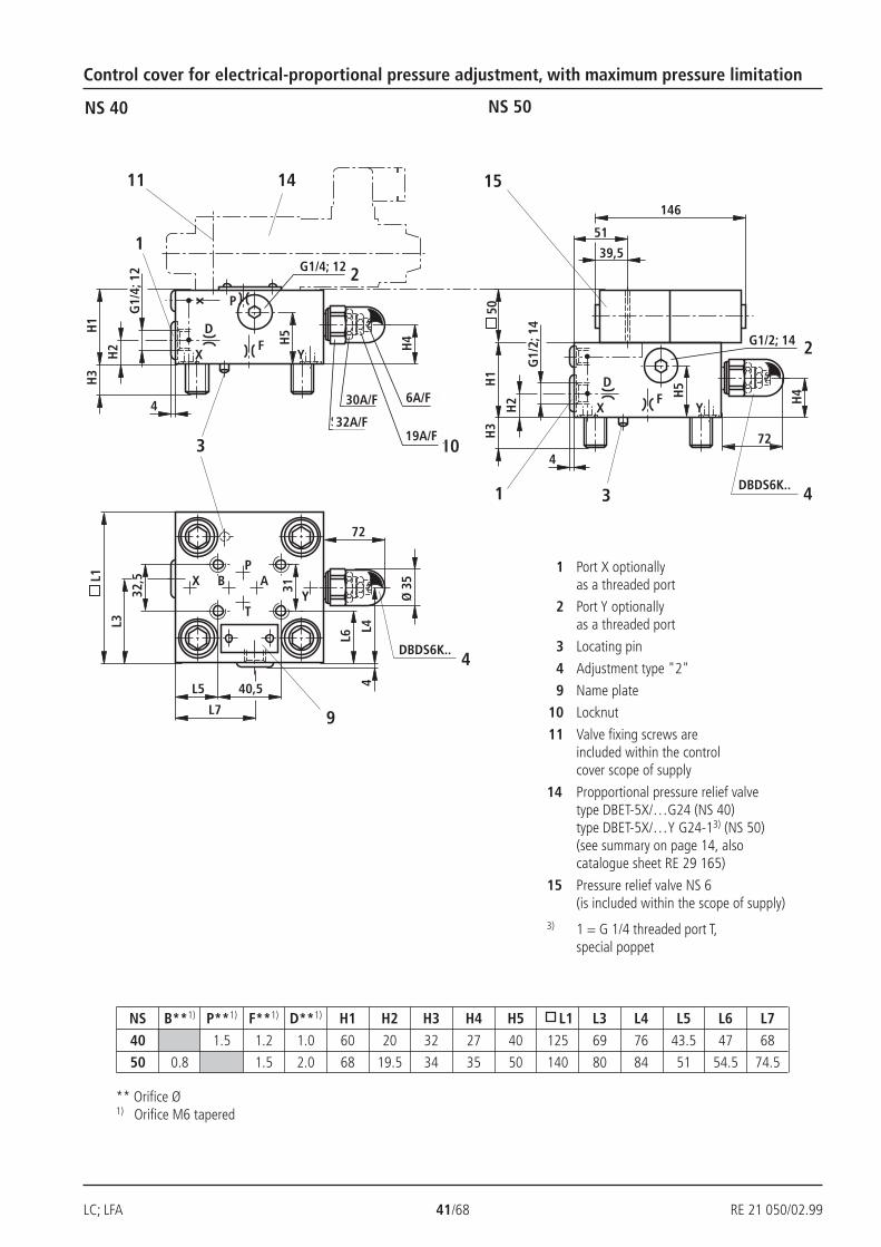
LC; LFA 41/68 RE 21 050/02.99
32,5
4
G1/
4; 1
2
H2
H1
H3
H4
D
XF
Y
3
XY
L4
L6
L1
L3
1
P
B AP
T
31
L5 40,5
11 14
H5
L7
4
Ø 3
5
72
DBDS6K..4
9
SW6
SW19
SW30
SW32
10
G1/4; 12 2
4
G1/
2; 1
4
H2
H1
H3
H4
D
XF
Y
1 5
0
146
51
39,5
H5
72
DBDS6K.. 43
G1/2; 14 2
15
NS 40
Control cover for electrical-proportional pressure adjustment, with maximum pressure limitation
NS 50
1 Port X optionallyas a threaded port
2 Port Y optionallyas a threaded port
3 Locating pin
4 Adjustment type "2"
9 Name plate
10 Locknut
11 Valve fixing screws areincluded within the controlcover scope of supply
14 Propportional pressure relief valvetype DBET-5X/…G24 (NS 40)type DBET-5X/…Y G24-13) (NS 50)(see summary on page 14, alsocatalogue sheet RE 29 165)
15 Pressure relief valve NS 6(is included within the scope of supply)
3) 1 = G 1/4 threaded port T,special poppet
** Orifice Ø1) Orifice M6 tapered
NS B**1) P**1) F**1) D**1) H1 H2 H3 H4 H5 L1 L3 L4 L5 L6 L7
40 1.5 1.2 1.0 60 20 32 27 40 125 69 76 43.5 47 68
50 0.8 1.5 2.0 68 19.5 34 35 50 140 80 84 51 54.5 74.5
30A/F
32A/F
6A/F
19A/F
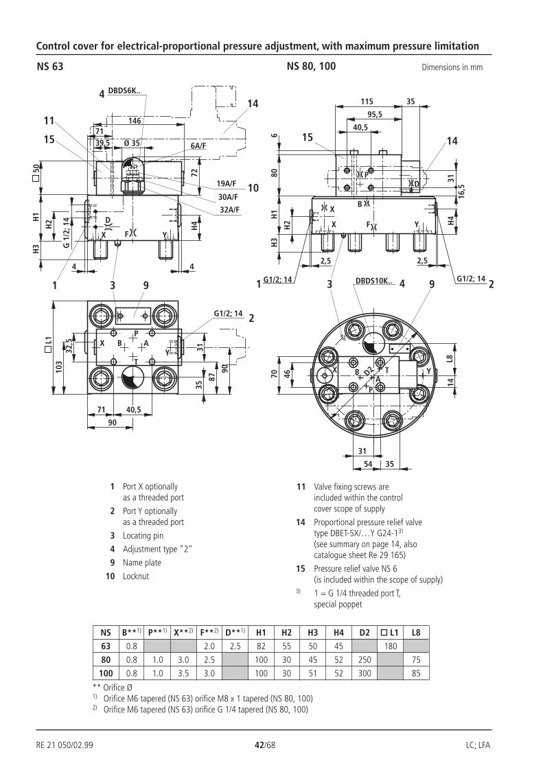
RE 21 050/02.99 42/68 LC; LFA
2,5
H2
H1
H3
40,5
DBDS10K..3 9 2
2,5
YFX
D2 YX
H4
G1/2; 141 G1/2; 14 4
B
46
1431
15
X
PD
TA
B
P
70
54 35
L8
806
3116
,5
14
95,5
115 3514
32,5
4
G 1
/2; 1
4
H2H
1H
3
H4D
X F Y
3
XY
90
90
87
L1
103
11
B AP
T
71 40,5
1
4
DBDS6K..4
35
G1/2; 14 2
9
50
72
15 SW6
SW19
SW30
SW32
10
71146
39,5 Ø 35
31
NS 63 Dimensions in mm
Control cover for electrical-proportional pressure adjustment, with maximum pressure limitation
NS 80, 100
** Orifice Ø1) Orifice M6 tapered (NS 63) orifice M8 x 1 tapered (NS 80, 100)2) Orifice M6 tapered (NS 63) orifice G 1/4 tapered (NS 80, 100)
1 Port X optionallyas a threaded port
2 Port Y optionallyas a threaded port
3 Locating pin
4 Adjustment type "2"
9 Name plate
10 Locknut
11 Valve fixing screws areincluded within the controlcover scope of supply
14 Proportional pressure relief valvetype DBET-5X/…Y G24-13)
(see summary on page 14, alsocatalogue sheet Re 29 165)
15 Pressure relief valve NS 6(is included within the scope of supply)
3) 1 = G 1/4 threaded port T,special poppet
NS B**1) P**1) X**2) F**2) D**1) H1 H2 H3 H4 D2 L1 L8
63 0.8 2.0 2.5 82 55 50 45 180
80 0.8 1.0 3.0 2.5 100 30 45 52 250 75
100 0.8 1.0 3.5 3.0 100 30 51 52 300 85
6A/F
19A/F
30A/F
32A/F
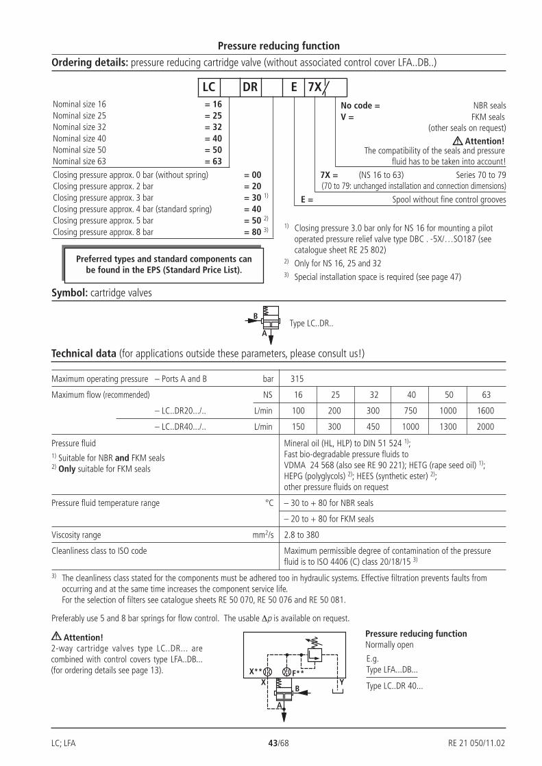
LC; LFA 43/68 RE 21 050/02.99
B
A
B
A
X YX** F**
Maximum operating pressure – Ports A and B bar 315
Maximum flow (recommended) NS 16 25 32 40 50 63
– LC..DR20.../.. L/min 100 200 300 750 1000 1600
– LC..DR40.../.. L/min 150 300 450 1000 1300 2000
Pressure fluid Mineral oil (HL, HLP) to DIN 51 524 1);Fast bio-degradable pressure fluids toVDMA 24 568 (also see RE 90 221); HETG (rape seed oil) 1);HEPG (polyglycols) 2); HEES (synthetic ester) 2);other pressure fluids on request
Pressure fluid temperature range °C – 30 to + 80 for NBR seals
– 20 to + 80 for FKM seals
Viscosity range mm2/s 2.8 to 380
Cleanliness class to ISO code Maximum permissible degree of contamination of the pressurefluid is to ISO 4406 (C) class 20/18/15 3)
Preferably use 5 and 8 bar springs for flow control. The usable ∆p is available on request.
Pressure reducing function
Ordering details: pressure reducing cartridge valve (without associated control cover LFA..DB..)
No code = NBR sealsV = FKM seals
(other seals on request)
Attention!The compatibility of the seals and pressure
fluid has to be taken into account!
7X = (NS 16 to 63) Series 70 to 79(70 to 79: unchanged installation and connection dimensions)
E = Spool without fine control grooves
Nominal size 16 = 16Nominal size 25 = 25Nominal size 32 = 32Nominal size 40 = 40Nominal size 50 = 50Nominal size 63 = 63
Closing pressure approx. 0 bar (without spring) = 00Closing pressure approx. 2 bar = 20Closing pressure approx. 3 bar = 30 1)
Closing pressure approx. 4 bar (standard spring) = 40Closing pressure approx. 5 bar = 50 2)
Closing pressure approx. 8 bar = 80 3)
LC DR E 7X
Preferred types and standard components canbe found in the EPS (Standard Price List).
1) Closing pressure 3.0 bar only for NS 16 for mounting a pilotoperated pressure relief valve type DBC . -5X/…SO187 (seecatalogue sheet RE 25 802)
2) Only for NS 16, 25 and 323) Special installation space is required (see page 47)
Symbol: cartridge valves
Technical data (for applications outside these parameters, please consult us!)
Pressure reducing functionNormally open
Attention!2-way cartridge valves type LC..DR... arecombined with control covers type LFA..DB...(for ordering details see page 13).
Type LC..DR..
E.g.Type LFA...DB...
Type LC..DR 40...
3) The cleanliness class stated for the components must be adhered too in hydraulic systems. Effective filtration prevents faults fromoccurring and at the same time increases the component service life.For the selection of filters see catalogue sheets RE 50 070, RE 50 076 and RE 50 081.
RE 21 050/11.02
1) Suitable for NBR and FKM seals2) Only suitable for FKM seals
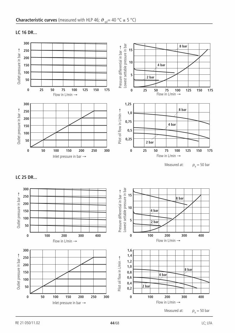
RE 21 050/02.99 44/68 LC; LFA
25 1750 50 75 100 125 150
5
10
158 bar
4 bar
2 bar
25 175
50
300
0
100
150
200
250
50 75 100 125 150
50 300
50
300
0 100 150 200 250
100
150
200
250
25 175
1,25
0
0,25
0,5
0,75
1,0
50 75 100 125 150
8 bar
4 bar
2 bar
50
300
0
100
150
200
250
100 200 300 400
50 300
50
300
0 100 150 200 250
100
150
200
250
0 100 200 300 400
5
10
158 bar
4 bar
2 bar
1,6
0
0,4
0,8
1,2
100 200 300 400
1,4
0,2
0,6
1,08 bar
4 bar
2 bar
Characteristic curves (measured with HLP 46; ϑ oil= 40 °C ± 5 °C)
LC 16 DR...
LC 25 DR...
Out
let p
ress
ure
in b
ar →
Flow in L/min → Flow in L/min →
Out
let p
ress
ure
in b
ar →
Pres
sure
diff
eren
tial i
n ba
r →Lo
wes
t set
tabl
e pr
essu
re in
bar
Inlet pressure in bar → Flow in L/min →
Pilo
t oil
flow
in L
/min
→
Out
let p
ress
ure
in b
ar →
Flow in L/min → Flow in L/min →
Out
let p
ress
ure
in b
ar →
Pres
sure
diff
eren
tial i
n ba
r →Lo
wes
t set
tabl
e pr
essu
re in
bar
Inlet pressure in bar → Flow in L/min →
Pilo
t oil
flow
in L
/min
→
Measured at: pa = 50 bar
Measured at: pa = 50 bar
RE 21 050/11.02

LC; LFA 45/68 RE 21 050/02.99
600
50
300
0
100
150
200
250
100 200 300 400 500
50 300
50
300
0 100 150 200 250
100
150
200
250
15
0
5
10
600100 200 300 400 500
8 bar
4 bar
2 bar
1,6
0
0,4
0,8
1,2
600100 200 300 400 500
1,4
0,2
0,6
1,08 bar
4 bar
2 bar
50 300
50
300
0 100 150 200 250
100
150
200
250
1000
50
300
0
100
150
250
200 400 600 800
200
15
0
5
10
1000200 400 600 800
8 bar
4 bar
2 bar
1,2
0
0,4
0,8
0,2
0,6
1,0
1000200 400 600 800
8 bar
4 bar2 bar
Characteristic curves (measured with HLP 46; ϑ oil = 40 °C ± 5 °C)
LC 32 DR...
LC 40 DR...
Out
let p
ress
ure
in b
ar →
Flow in L/min → Flow in L/min →
Out
let p
ress
ure
in b
ar →
Pres
sure
diff
eren
tial i
n ba
r →Lo
wes
t set
tabl
e pr
essu
re in
bar
Inlet pressure in bar → Flow in L/min →
Pilo
t oil
flow
in L
/min
→
Out
let p
ress
ure
in b
ar →
Flow in L/min → Flow in L/min →
Out
let p
ress
ure
in b
ar →
Pres
sure
diff
eren
tial i
n ba
r →Lo
wes
t set
tabl
e pr
essu
re in
bar
Inlet pressure in bar → Flow in L/min →
Pilo
t oil
flow
in L
/min
→
Measured at: pa = 50 bar
Vers
ion
20
Measured at: pa = 50 bar
RE 21 050/11.02
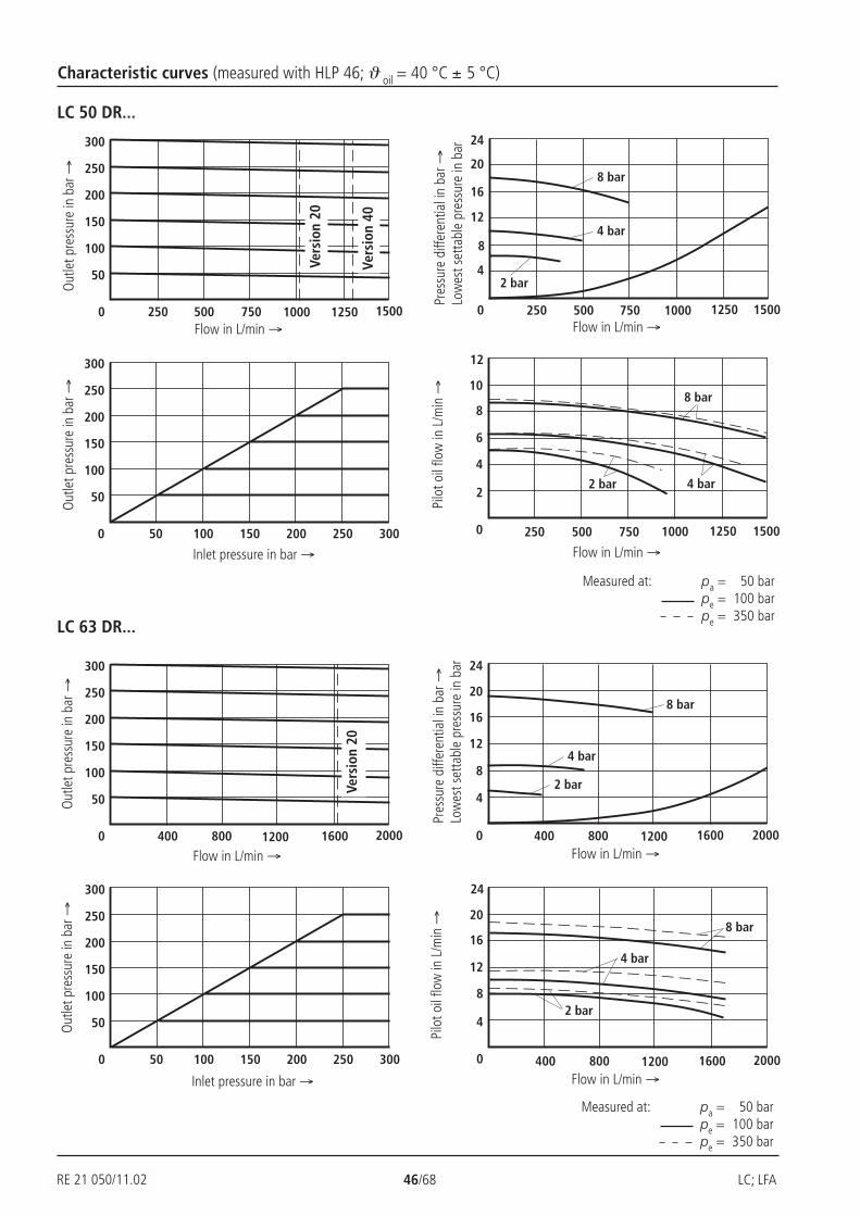
RE 21 050/02.99 46/68 LC; LFA
50 300
50
300
0 100 150 200 250
100
150
200
250
50 300
50
300
0 100 150 200 250
100
150
200
250
1500
50
300
0
100
150
250
250 500 750 1000
200
1250
24
0
8
16
1500250 500 750 1000
8 bar
4 bar
2 bar4
12
20
1250
2000
50
300
0
100
150
250
400 800 1200 1600
200
24
0
8
16
2000400 800 1200 1600
8 bar
4 bar
2 bar4
12
20
24
0
8
16
4
12
20
2000400 800 1200 1600
8 bar
4 bar
2 bar
Characteristic curves (measured with HLP 46; ϑ oil = 40 °C ± 5 °C)
LC 50 DR...
LC 63 DR...
Out
let p
ress
ure
in b
ar →
Flow in L/min → Flow in L/min →
Out
let p
ress
ure
in b
ar →
Pres
sure
diff
eren
tial i
n ba
r →Lo
wes
t set
tabl
e pr
essu
re in
bar
Inlet pressure in bar → Flow in L/min →
Pilo
t oil
flow
in L
/min
→
Out
let p
ress
ure
in b
ar →
Flow in L/min → Flow in L/min →
Out
let p
ress
ure
in b
ar →
Pres
sure
diff
eren
tial i
n ba
r →Lo
wes
t set
tabl
e pr
essu
re in
bar
Inlet pressure in bar → Flow in L/min →
Pilo
t oil
flow
in L
/min
→
Vers
ion
20
Vers
ion
40Ve
rsio
n 20
Measured at: pa = 50 barpe = 100 barpe = 350 bar
Measured at: pa = 50 barpe = 100 barpe = 350 bar
RE 21 050/11.02
12
0
4
8
2
6
10
1500250 500 750 1000
8 bar
4 bar2 bar
1250

LC; LFA 47/68 RE 21 050/02.99
Seal kits for cartridge valves type LC...Nom. size Material No.
NBR seals FKM seals16 R900313104 R90031310725 R900313105 R90031310832 R900313106 R900313109
Nom. size Material No.NBR seals FKM seals
40 R900873022 R90087302550 R900873023 R90087302663 R900873024 R900873027
Compression springs for cartridge valves type LC...NS Spring dimensions Opening Material
in mm pressure in bar No.
10.2/1.3 x 40.5/8.0 2.0 R90006274710.0/1.6 x 38.2/9.0 3.0 R900062753
16 9.8/1.7 x 38.0/9.0 4.0 R9000627549.7/1.9 x 35.7/8.5 5.0 R900062757
9.2/2.4 x 60.5/14.5 8.0 1) R90008207315.3/2.25 x 55.0/8.0 2.0 R90006276214.9/2.7 x 53.4/8.5 3.0 R900062764
25 14.7/2.8 x 53.5/8.5 4.0 R90006282014.6/3.0 x 52.5/8.5 5.0 R900062819
14.1/3.5 x 78.5/12.0 8.0 1) R90008207219.6/2.8 x 69.5/7.5 2.0 R90006281319.2/3.2 x 71.0/8.5 3.0 R900062783
32 19.1/3.4 x 72.0/9.5 4.0 R90006281019.1/3.5 x 72.8/9.0 5.0 R90006280518.5/4.0 x 109/14.5 8.0 1) R900082071
NS Spring dimensions Opening Material in mm pressure in bar No.
25.9/4.25 x 63/6 2.0 R90020667540 25.7/4.5 x 68.5/6 4.0 R900206673
24.8/5.3 x 105/10 8.0 1) R90020667133.2/5 x 82/5.5 2.0 R900206684
50 32.8/5.3 x 92/6.5 4.0 R90020668131.7/6.5 x 137/10.5 8.0 1) R900206680
40.6/6.5 x 108/7 2.0 R90020669063 40.7/6.5 x 127.5/7.5 4.0 R900206692
38.6/8.5 x 183.5/11.5 8.0 1) R900206689
1) These springs require an additional installation length.When using standaard control covers an additional sandwichplate type LFA . D22… must be used.
Exception:Control cover type "D" can be replaced by type LFA . D8-../F(no sandwich plate is required).
RE 21 050/11.02
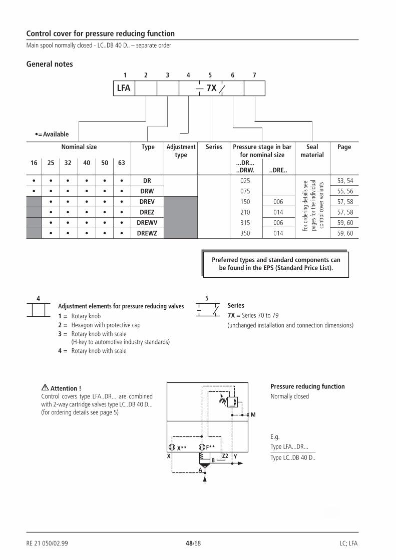
RE 21 050/02.99 48/68 LC; LFA
X YX** F**
M
A
BZ2
54
Control cover for pressure reducing function
1 2 3 4 5 6 7
Nominal size Type Adjustment Series Pressure stage in bar Seal Pagetype for nominal size material
16 25 32 40 50 63 ...DR.....DRW. ..DRE..
• • • • • • DR 025 53, 54
• • • • • • DRW 075 55, 56
• • • • • DREV 150 006 57, 58
• • • • • DREZ 210 014 57, 58
• • • • • DREWV 315 006 59, 60
• • • • • DREWZ 350 014 59, 60
For o
rder
ing
deta
ils se
e p
ages
for t
he in
divid
ual
cont
rol c
over
varia
nts
Adjustment elements for pressure reducing valves
1 = Rotary knob2 = Hexagon with protective cap3 = Rotary knob with scale
(H-key to automotive industry standards)4 = Rotary knob with scale
Series
7X = Series 70 to 79
(unchanged installation and connection dimensions)
Main spool normally closed - LC..DB 40 D.. – separate order
LFA 7X
•= Available
General notes
Pressure reducing function
Normally closed Attention !
Control covers type LFA..DR... are combinedwith 2-way cartridge valves type LC..DB 40 D...(for ordering details see page 5)
E.g.
Type LFA...DR...
Type LC..DB 40 D..
Preferred types and standard components canbe found in the EPS (Standard Price List).
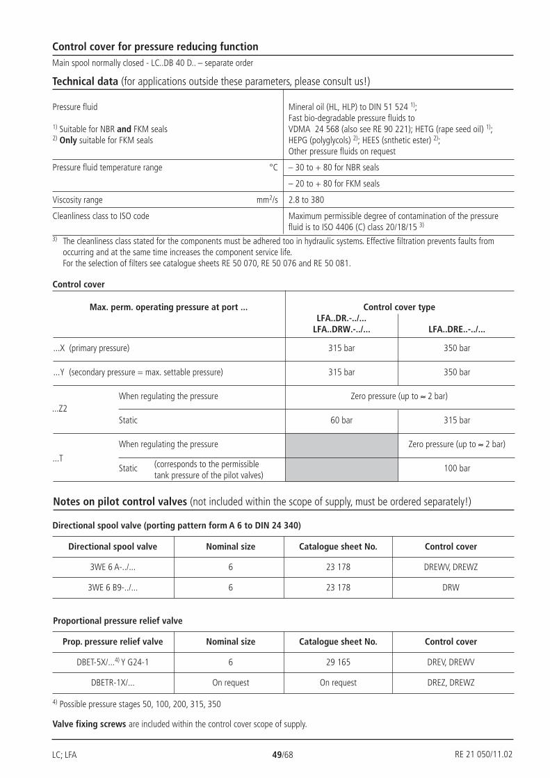
LC; LFA 49/68 RE 21 050/02.99
Control cover for pressure reducing functionMain spool normally closed - LC..DB 40 D.. – separate order
Technical data (for applications outside these parameters, please consult us!)
Control cover
Notes on pilot control valves (not included within the scope of supply, must be ordered separately!)
Pressure fluid Mineral oil (HL, HLP) to DIN 51 524 1);Fast bio-degradable pressure fluids to
1) Suitable for NBR and FKM seals VDMA 24 568 (also see RE 90 221); HETG (rape seed oil) 1);2) Only suitable for FKM seals HEPG (polyglycols) 2); HEES (snthetic ester) 2);
Other pressure fluids on request
Pressure fluid temperature range °C – 30 to + 80 for NBR seals
– 20 to + 80 for FKM seals
Viscosity range mm2/s 2.8 to 380
Cleanliness class to ISO code Maximum permissible degree of contamination of the pressurefluid is to ISO 4406 (C) class 20/18/15 3)
Max. perm. operating pressure at port ... Control cover typeLFA..DR.-../...
LFA..DRW.-../... LFA..DRE..-../...
...X (primary pressure) 315 bar 350 bar
...Y (secondary pressure = max. settable pressure) 315 bar 350 bar
When regulating the pressure Zero pressure (up to ≈ 2 bar)
Static 60 bar 315 bar
When regulating the pressure Zero pressure (up to ≈ 2 bar)
Static 100 bar(corresponds to the permissibletank pressure of the pilot valves)
...Z2
...T
Directional spool valve (porting pattern form A 6 to DIN 24 340)
Proportional pressure relief valve
Valve fixing screws are included within the control cover scope of supply.
4) Possible pressure stages 50, 100, 200, 315, 350
Directional spool valve Nominal size Catalogue sheet No. Control cover
3WE 6 A-../... 6 23 178 DREWV, DREWZ
3WE 6 B9-../... 6 23 178 DRW
Prop. pressure relief valve Nominal size Catalogue sheet No. Control cover
DBET-5X/...4) Y G24-1 6 29 165 DREV, DREWV
DBETR-1X/... On request On request DREZ, DREWZ
3) The cleanliness class stated for the components must be adhered too in hydraulic systems. Effective filtration prevents faults fromoccurring and at the same time increases the component service life.For the selection of filters see catalogue sheets RE 50 070, RE 50 076 and RE 50 081.
RE 21 050/11.02
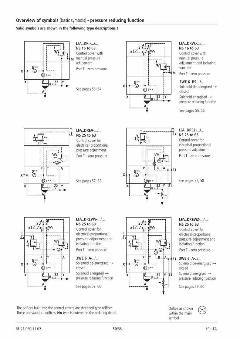
RE 21 050/02.99 50/68 LC; LFA
D**
F**X
X
A
B Z2 Y
M
D**
F**
X
X
A
BZ2 Y
T
P
P T AD**
F**
X
X
A
BZ2 Y
T
P
P T AB Z1
Z1
T
D**
F**X
X
A
BZ2 Y
TP
P T A
T
A B
a
T
D**
F**X
X
A
BZ2 Y
TP
P T AB Z1
Z1
T
A B
a
T
D**
F**X
X
A
BZ2 Y
P T
A B
a
M
Overview of symbols (basic symbols) - pressure reducing function
Valid symbols are shown in the following type descriptions !
The orifices built into the control covers are threaded type orifices.These are standard orifices. No type is entered in the ordering detail.
Orifice as shownwithin the mainsymbol
LFA..DREWV-.../...NS 25 to 63Control cover forelectrical-proportionalpressure adjustment andisolating function
Port T - zero pressure
See pages 59; 60
LFA..DREWZ-.../...NS 25 to 63Control cover forelectrical-proportionalpressure adjustment andisolating function
Port T - zero pressure
See pages 59; 60
LFA..DREV-.../...NS 25 to 63Control cover forelectrical-proportionalpressure adjustment
Port T - zero pressure
See pages 57; 58
LFA..DREZ-.../...NS 25 to 63Control cover forelectrical-proportionalpressure adjustment
Port T - zero pressure
See pages 57; 58
LFA..DR.-.../...NS 16 to 63Control cover withmanual pressureadjustment
Port T - zero pressure
See pages 53; 54
LFA..DRW.-.../...NS 16 to 63Control cover withmanual pressureadjustment and isolatingfunction
Port T - zero pressure
3WE 6 B9-../..Solenoid de-energised →closedSolenoid energised →pressure reducing function
See pages 55; 56
3WE 6 A-../..Solenoid de-energised →closedSolenoid energised →pressure reducing function
3WE 6 A-../..Solenoid de-energised →closedSolenoid energised →pressure reducing function
RE 21 050/11.02
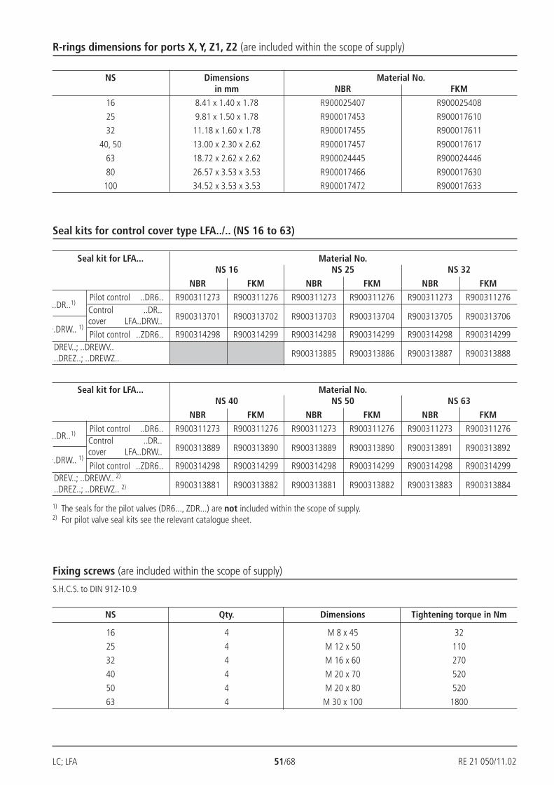
LC; LFA 51/68 RE 21 050/02.99
R-rings dimensions for ports X, Y, Z1, Z2 (are included within the scope of supply)
NS Dimensions Material No.in mm NBR FKM
16 8.41 x 1.40 x 1.78 R900025407 R900025408
25 9.81 x 1.50 x 1.78 R900017453 R900017610
32 11.18 x 1.60 x 1.78 R900017455 R900017611
40, 50 13.00 x 2.30 x 2.62 R900017457 R900017617
63 18.72 x 2.62 x 2.62 R900024445 R900024446
80 26.57 x 3.53 x 3.53 R900017466 R900017630
100 34.52 x 3.53 x 3.53 R900017472 R900017633
Seal kits for control cover type LFA../.. (NS 16 to 63)
Fixing screws (are included within the scope of supply)
S.H.C.S. to DIN 912-10.9
NS Qty. Dimensions Tightening torque in Nm
16 4 M 8 x 45 32
25 4 M 12 x 50 110
32 4 M 16 x 60 270
40 4 M 20 x 70 520
50 4 M 20 x 80 520
63 4 M 30 x 100 1800
1) The seals for the pilot valves (DR6..., ZDR...) are not included within the scope of supply.2) For pilot valve seal kits see the relevant catalogue sheet.
Seal kit for LFA... Material No.NS 16 NS 25 NS 32
NBR FKM NBR FKM NBR FKMPilot control ..DR6.. R900311273 R900311276 R900311273 R900311276 R900311273 R900311276
R900313701 R900313702 R900313703 R900313704 R900313705 R900313706
Pilot control ..ZDR6.. R900314298 R900314299 R900314298 R900314299 R900314298 R900314299
R900313885 R900313886 R900313887 R900313888
Control ..DR..cover LFA..DRW..
DREV..; ..DREWV....DREZ..; ..DREWZ..
..DR..1)
..DRW.. 1)
Seal kit for LFA... Material No.NS 40 NS 50 NS 63
NBR FKM NBR FKM NBR FKM
Pilot control ..DR6.. R900311273 R900311276 R900311273 R900311276 R900311273 R900311276
R900313889 R900313890 R900313889 R900313890 R900313891 R900313892
Pilot control ..ZDR6.. R900314298 R900314299 R900314298 R900314299 R900314298 R900314299
R900313881 R900313882 R900313881 R900313882 R900313883 R900313884
Control ..DR..cover LFA..DRW..
DREV..; ..DREWV.. 2)
..DREZ..; ..DREWZ.. 2)
..DR..1)
..DRW.. 1)
RE 21 050/11.02
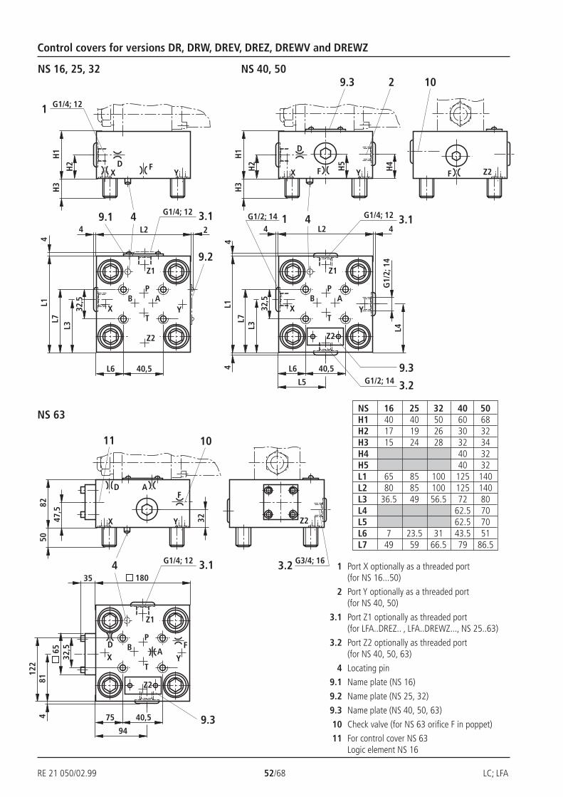
RE 21 050/02.99 52/68 LC; LFA
H2
H1
H3
DX
FY
4
X Y
L7L1
L3
1
B AP
T
L6 40,5
9.2
L23.1G1/4; 12
Z1
Z2
G1/4; 12
4
4
29.1
32,5
YH2
H1
H3
D
X F
4
X Y
L7
L1
L3
9.3
B AP
T
32,5
L6 40,5
L23.1G1/4; 12
Z1
Z2
4
3.2G1/2; 14
41G1/2; 14
L4G
1/2;
14
2
H4H5
4
L5
4
9.3
F Z2
10
Y47,5
8250
D
X
F
4
X Y
81
11
B A
P
T
75 40,5
3.1G1/4; 12
Z1
Z2
35
4
32
10
A
65
180
949.3
D F
32,5
122
3.2 G3/4; 16
Z2
NS 16, 25, 32
Control covers for versions DR, DRW, DREV, DREZ, DREWV and DREWZ
NS 40, 50
NS 63NS 16 25 32 40 50H1 40 40 50 60 68H2 17 19 26 30 32H3 15 24 28 32 34H4 40 32H5 40 32L1 65 85 100 125 140L2 80 85 100 125 140L3 36.5 49 56.5 72 80L4 62.5 70L5 62.5 70L6 7 23.5 31 43.5 51L7 49 59 66.5 79 86.5
1 Port X optionally as a threaded port(for NS 16...50)
2 Port Y optionally as a threaded port(for NS 40, 50)
3.1 Port Z1 optionally as threaded port(for LFA..DREZ.. , LFA..DREWZ..., NS 25..63)
3.2 Port Z2 optionally as threaded port(for NS 40, 50, 63)
4 Locating pin
9.1 Name plate (NS 16)
9.2 Name plate (NS 25, 32)
9.3 Name plate (NS 40, 50, 63)
10 Check valve (for NS 63 orifice F in poppet)
11 For control cover NS 63Logic element NS 16

LC; LFA 53/68 RE 21 050/02.99
X
A
D**
X**YZ2
B
M
X
ATP
D**X
F**
A
YZ2B
M
X
ATP
D**
F**Z2Y
X
A
YZ2B
M
X
ATP
D**
F**Z2
A**
A
YZ2B
M
X
ATP
Control cover for pressure reducing functionsMain spool normally closed - LC..DB 40 D.. – separate order
NS 16 to 63
Nominal size 16 = 16Nominal size 25 = 25Nominal size 32 = 32Nominal size 40 = 40Nominal size 50 = 50Nominal size 63 = 63
1 2 3 4 5 6 7
No code = NBR sealsV = FKM seals
(other seals on request)
Attention!The compatibility of the seals and pressure
fluid has to be taken into account!
LFA DR 7X
LFA..DR.-7X/...NS 40, 50
LFA..DR.-7X/...NS 25, 32
LFA..DR.-7X/...NS 16
LFA..DR.-7X/...NS 63
025 = Max. secondary pressure 25 bar075 = Max. secondary pressure 75 bar150 = Max. secondary pressure 150 bar210 = Max. secondary pressure 210 bar315 = Max. secondary pressure 315 bar
7X = Series 7X (NS 16 to 63)1) H-key to Material No. R900008158 is included within the scope of supply
Adjustment type
Rotary knob = 1Set screw with hexagon and protective cap = 2Lockable rotary knob with scale = 31)
Rotary knob with scale = 4
RE 21 050/11.02
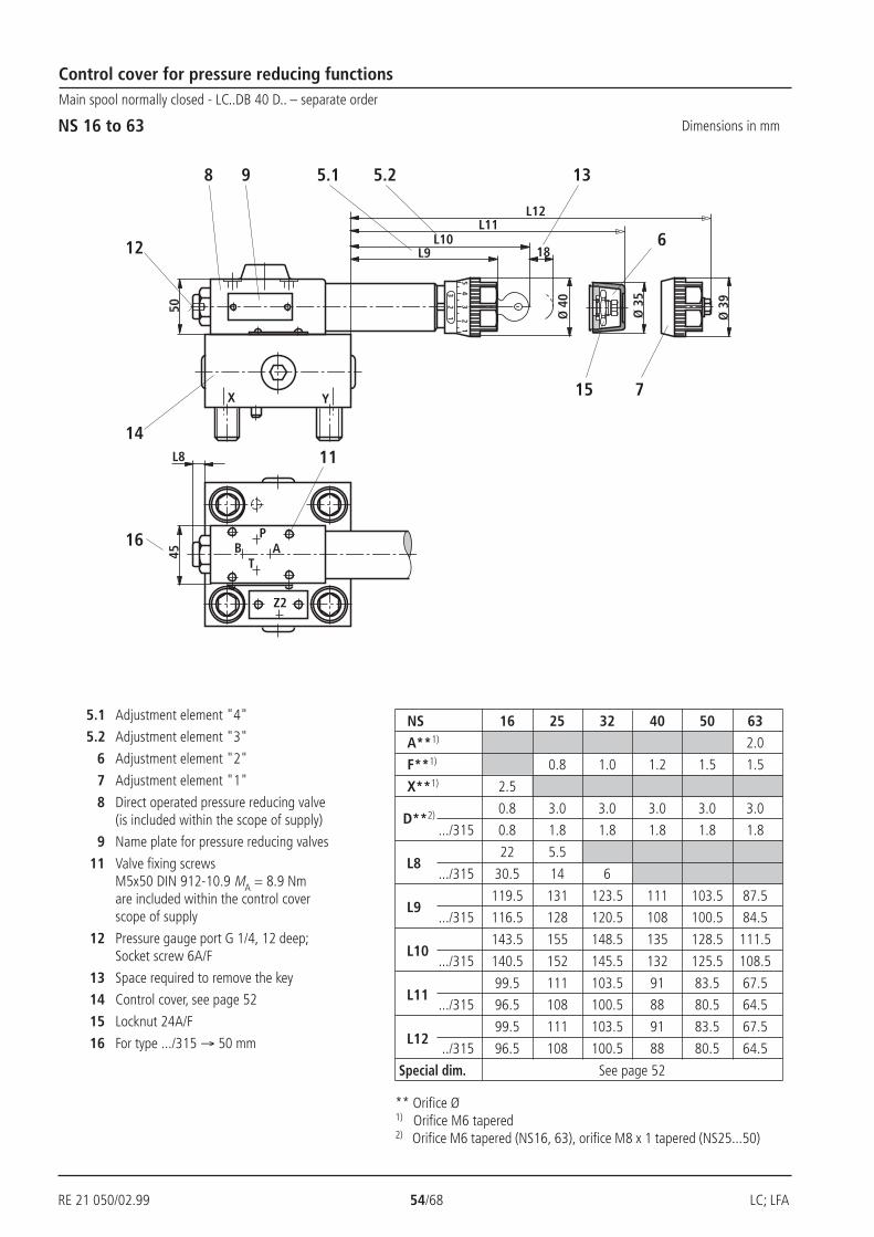
RE 21 050/02.99 54/68 LC; LFA
AT
PB
Z2
X Y
32 3
45
21
1
L9
Ø 4
0
L1018
50
L11L12
Ø 3
5
Ø 3
9
L8
135.25.18
12
14
16
45
11
6
15 7
9
Control cover for pressure reducing functionsMain spool normally closed - LC..DB 40 D.. – separate order
NS 16 to 63 Dimensions in mm
5.1 Adjustment element "4"
5.2 Adjustment element "3"
6 Adjustment element "2"
7 Adjustment element "1"
8 Direct operated pressure reducing valve(is included within the scope of supply)
9 Name plate for pressure reducing valves
11 Valve fixing screwsM5x50 DIN 912-10.9 MA = 8.9 Nmare included within the control coverscope of supply
12 Pressure gauge port G 1/4, 12 deep;Socket screw 6A/F
13 Space required to remove the key
14 Control cover, see page 52
15 Locknut 24A/F
16 For type .../315 → 50 mm
NS 16 25 32 40 50 63A**1) 2.0
F**1) 0.8 1.0 1.2 1.5 1.5
X**1) 2.5
0.8 3.0 3.0 3.0 3.0 3.0
.../315 0.8 1.8 1.8 1.8 1.8 1.8
22 5.5
.../315 30.5 14 6
119.5 131 123.5 111 103.5 87.5
.../315 116.5 128 120.5 108 100.5 84.5
143.5 155 148.5 135 128.5 111.5
.../315 140.5 152 145.5 132 125.5 108.5
99.5 111 103.5 91 83.5 67.5
.../315 96.5 108 100.5 88 80.5 64.5
99.5 111 103.5 91 83.5 67.5
../315 96.5 108 100.5 88 80.5 64.5
Special dim. See page 52
L8
L9
L10
L11
L12
D**2)
** Orifice Ø1) Orifice M6 tapered2) Orifice M6 tapered (NS16, 63), orifice M8 x 1 tapered (NS25...50)
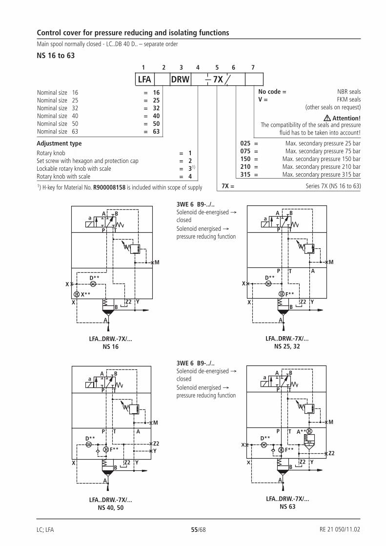
LC; LFA 55/68 RE 21 050/02.99
X
A
D**
X**YZ2
B
M
X
A B
P T
a
Z2Y
P T A
F**
A
D**
YZ2B
M
X
A B
P T
a
Z2
A**
F**X
A
D**
YZ2B
M
X
A B
P T
a
P T
F**
X
A
D**
YZ2B
M
X
A B
P T
a
P T A
Control cover for pressure reducing and isolating functionsMain spool normally closed - LC..DB 40 D.. – separate order
NS 16 to 63
Nominal size 16 = 16Nominal size 25 = 25Nominal size 32 = 32Nominal size 40 = 40Nominal size 50 = 50Nominal size 63 = 63
1 2 3 4 5 6 7
No code = NBR sealsV = FKM seals
(other seals on request)
Attention!The compatibility of the seals and pressure
fluid has to be taken into account!
LFA DRW 7X
LFA..DRW.-7X/...NS 40, 50
LFA..DRW.-7X/...NS 25, 32
LFA..DRW.-7X/...NS 16
LFA..DRW.-7X/...NS 63
Adjustment type
Rotary knob = 1Set screw with hexagon and protection cap = 2Lockable rotary knob with scale = 31)
Rotary knob with scale = 4
025 = Max. secondary pressure 25 bar075 = Max. secondary pressure 75 bar150 = Max. secondary pressure 150 bar210 = Max. secondary pressure 210 bar315 = Max. secondary pressure 315 bar
7X = Series 7X (NS 16 to 63)1) H-key for Material No. R900008158 is included within scope of supply
3WE 6 B9-../..Solenoid de-energised →closedSolenoid energised →pressure reducing function
3WE 6 B9-../..Solenoid de-energised →closedSolenoid energised →pressure reducing function
RE 21 050/11.02
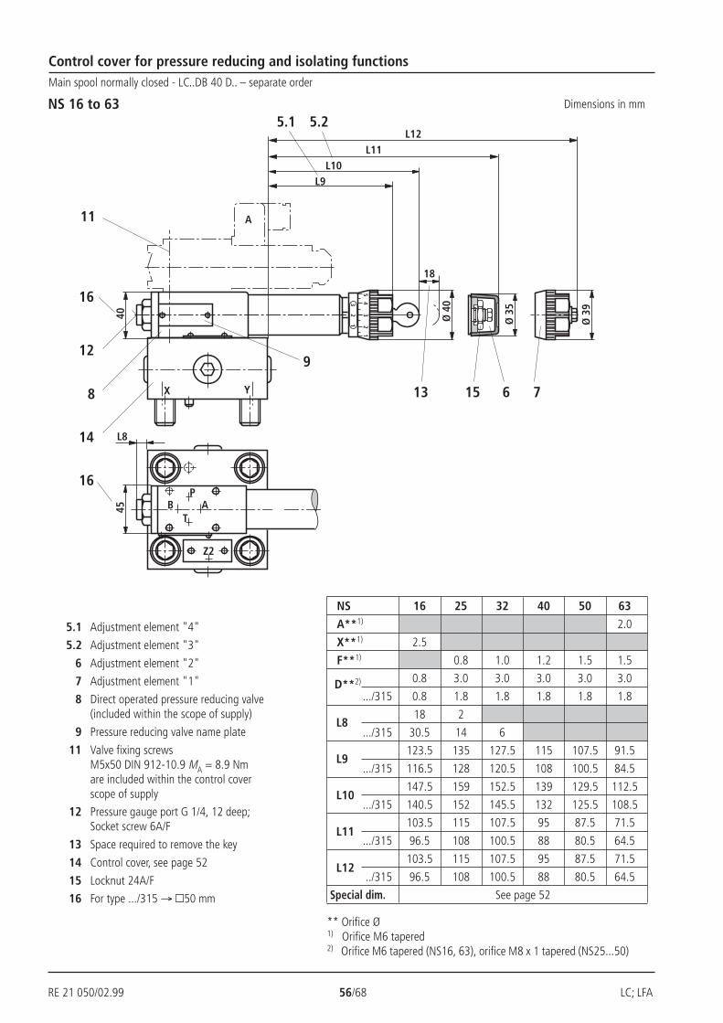
RE 21 050/02.99 56/68 LC; LFA
X Y
B AP
T
Z2
Ø 3
9
Ø 3
5
Ø 4
0
40
18
34
52
1
32
1
L12
L8
45
L11L10
L9
15 7
5.2
912
8
14
16
5.1
13 6
11 A
16
Control cover for pressure reducing and isolating functionsMain spool normally closed - LC..DB 40 D.. – separate order
NS 16 to 63 Dimensions in mm
NS 16 25 32 40 50 63
A**1) 2.0
X**1) 2.5
F**1) 0.8 1.0 1.2 1.5 1.5
0.8 3.0 3.0 3.0 3.0 3.0
.../315 0.8 1.8 1.8 1.8 1.8 1.8
18 2
.../315 30.5 14 6
123.5 135 127.5 115 107.5 91.5
.../315 116.5 128 120.5 108 100.5 84.5
147.5 159 152.5 139 129.5 112.5
.../315 140.5 152 145.5 132 125.5 108.5
103.5 115 107.5 95 87.5 71.5
.../315 96.5 108 100.5 88 80.5 64.5
103.5 115 107.5 95 87.5 71.5
../315 96.5 108 100.5 88 80.5 64.5
Special dim. See page 52
L8
L9
L10
L11
L12
D**2)
** Orifice Ø1) Orifice M6 tapered2) Orifice M6 tapered (NS16, 63), orifice M8 x 1 tapered (NS25...50)
5.1 Adjustment element "4"
5.2 Adjustment element "3"
6 Adjustment element "2"
7 Adjustment element "1"
8 Direct operated pressure reducing valve(included within the scope of supply)
9 Pressure reducing valve name plate
11 Valve fixing screwsM5x50 DIN 912-10.9 MA = 8.9 Nmare included within the control coverscope of supply
12 Pressure gauge port G 1/4, 12 deep;Socket screw 6A/F
13 Space required to remove the key
14 Control cover, see page 52
15 Locknut 24A/F
16 For type .../315 → 50 mm
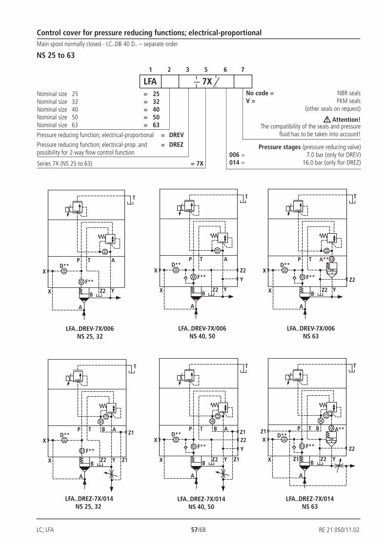
LC; LFA 57/68 RE 21 050/02.99
D**
F**
X
X
A
BZ2 Y
T
P T AD**
F**X
X
A
BZ2 Y
T
P T A
Z2
Y
D**
F**X
X
A
BZ2 Y
T
P T A**
Z2
D**
F**
X
X
A
BZ2 Y
T
P T AB Z1
Z1
D**
F**X
X
A
BZ2 Y
T
P T A**
Z2
BZ1
Z1
D**
F**X
X
A
BZ2 Y
T
P T A
Z2
Y
Z1
Z1
B
Control cover for pressure reducing functions; electrical-proportionalMain spool normally closed - LC..DB 40 D.. – separate order
NS 25 to 63
1 2 3 5 6 7
Series 7X (NS 25 to 63) = 7X
Pressure stages (pressure reducing valve)006 = 7.0 bar (only for DREV)014 = 16.0 bar (only flor DREZ)
Nominal size 25 = 25Nominal size 32 = 32Nominal size 40 = 40Nominal size 50 = 50Nominal size 63 = 63
No code = NBR sealsV = FKM seals
(other seals on request)
Attention!The compatibility of the seals and pressure
fluid has to be taken into account!
LFA 7X
Pressure reducing function; electrical-proportional = DREV
Pressure reducing function; electrical-prop. and = DREZpossibility for 2-way flow control function
LFA..DREV-7X/006NS 63
LFA..DREV-7X/006NS 40, 50
LFA..DREV-7X/006NS 25, 32
LFA..DREZ-7X/014NS 25, 32
LFA..DREZ-7X/014NS 40, 50
LFA..DREZ-7X/014NS 63
RE 21 050/11.02
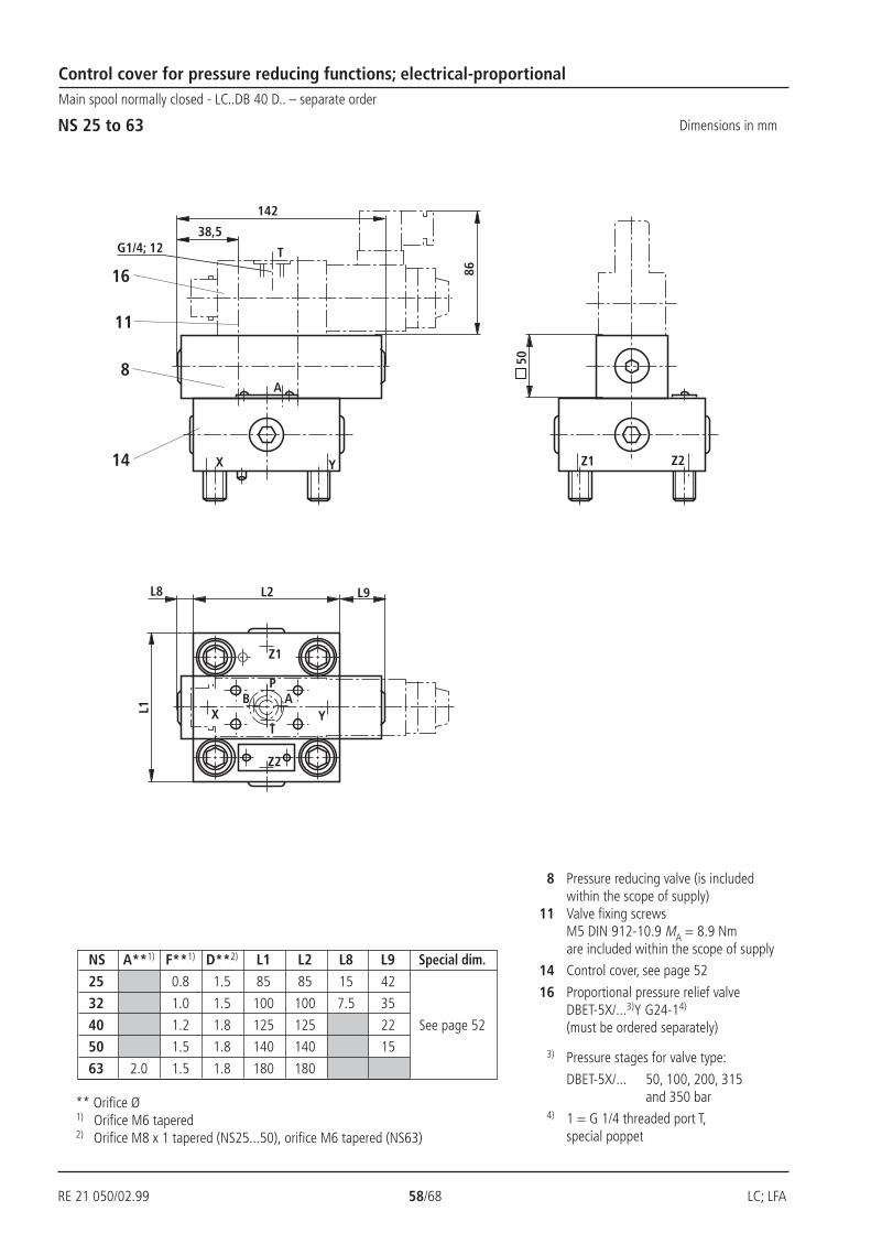
RE 21 050/02.99 58/68 LC; LFA
YX
X YB A
P
T
L2
Z1
Z2
Z2
16
Z1
L8
L1
50
A
86
T
142
38,5G1/4; 12
11
14
8
L9
Control cover for pressure reducing functions; electrical-proportionalMain spool normally closed - LC..DB 40 D.. – separate order
NS 25 to 63 Dimensions in mm
8 Pressure reducing valve (is includedwithin the scope of supply)
11 Valve fixing screwsM5 DIN 912-10.9 MA = 8.9 Nmare included within the scope of supply
14 Control cover, see page 52
16 Proportional pressure relief valveDBET-5X/...3)Y G24-14)
(must be ordered separately)
3) Pressure stages for valve type:
DBET-5X/... 50, 100, 200, 315and 350 bar
4) 1 = G 1/4 threaded port T,special poppet
** Orifice Ø1) Orifice M6 tapered2) Orifice M8 x 1 tapered (NS25...50), orifice M6 tapered (NS63)
NS A**1) F**1) D**2) L1 L2 L8 L9 Special dim.
25 0.8 1.5 85 85 15 42
32 1.0 1.5 100 100 7.5 35
40 1.2 1.8 125 125 22 See page 52
50 1.5 1.8 140 140 15
63 2.0 1.5 1.8 180 180

LC; LFA 59/68 RE 21 050/02.99
D**
F**
X
X
A
B Z2 Y
P T A
A
B
a
P
T
P
T
D**
F**X
X
A
B Z2
P T A
Z2
Y
Y
A
B
a
P
T
P
T
D**
F**X
X
A
BZ2 Y
P T A**
Z2
A
B
P
T
P
T
D**
F**
X
X
A
BZ2 Y
P T A
A
B
a
P
T
P
T
Z1
Z1
BD**
F**X
X
A
BZ2
P T A
Z2
Y
Y
A
B
a
P
T
P
T
Z1
Z1
BD**
F**X
X
A
BZ2 Y
P T A**
Z2
A
B
P
T
P
T
Z1
Z1
Control cover for pressure reducing functions and isolating functions; electrical-proportionalMain spool normally closed - LC..DB 40 D.. – separate order
NS 25 to 63 1 2 3 5 6 7
= 7X Series 7X (NS 25 to 63)
Pressure stages006 = 7.0 bar (only for DREWV)014 = 16.0 bar (only for DREWZ)
Nominal size 25 = 25Nominal size 32 = 32Nominal size 40 = 40Nominal size 50 = 50Nominal size 63 = 63
No code = NBR sealsV = FKM seals
(other seals on request)
Attention!The compatibility of the seals and pressure
fluid has to be taken into account!
LFA 7X
Pressure reducing function, = DREWVelectrical-proportional and isolating function
Pressure reducing function, electr.-prop. and = DREWZisolating function, including possibility for2-way flow control function
LFA..DREWV-7X/006NS 25, 32
LFA..DREWV-7X/006NS 40, 50
LFA..DREWV-7X/006NS 63
LFA..DREWZ-7X/014NS 63
LFA..DREWZ-7X/014NS 40, 50
LFA..DREWZ-7X/014NS 25, 32
1 1 1
1 1 1
1 3WE 6 A-../.. Solenoid de-energised → closedSolenoid energised → pressure reducing function

RE 21 050/02.99 60/68 LC; LFA
38,5
142
Z1 Z2YX
T
Z1
Z2
P
T
B A YX
L2L8
L1
8
14
1611 11G1/4; 12
L9
L10
17
50
Control cover for pressure reducing functions and isolating functions; electrical-proportionalMain spool normally closed - LC..DB 40 D.. – separate order
NS 25 to 63 Dimensions in mm
8 Pressured reducing valve (is includedwithin the scope of supply)
11 Valve fixing screwsM5 DIN 912-10.9 MA = 8.9 Nmare included with the scope of supply
14 Control cover, see page 52
16 Proportional pressure relief valveDBET-5X/...3)Y G24-14)
(must be ordered separately,see page 49)
17 Directional spool valve 3WE 6 A...(must be ordered separately,see page 49)
3) Pressure stages of valve type:
DBET-5X/... 50, 100, 200, 315and 350 bar
4) 1 = G 1/4 threaded port T,special port
** Orifice Ø1) Orifice M6 tapered2) Orifice M8 x 1 tapered (NS 25...50), orifice M6 tapered (NS 63)
NS A**1) F**1) D**2) L1 L2 L8 L9 L10 Special dim.
25 0.8 1.5 85 85 15 42 30
32 1.0 1.5 100 100 7.5 35 37.5
40 1.2 1.8 125 125 22 50 See page 52
50 1.5 1.8 140 140 15 57.5
63 2.0 1.5 1.8 180 180 81.5
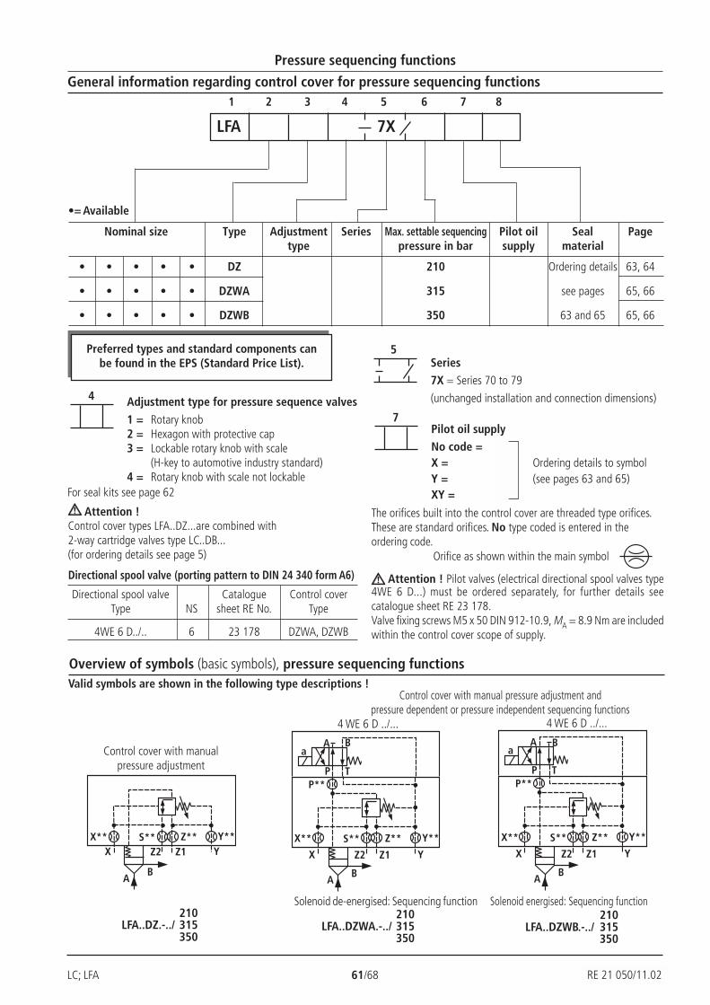
LC; LFA 61/68 RE 21 050/02.99
X
A
YZ1
B
Z2X** S** Z** Y**
X
A
YZ1
B
P T
A Ba
Z2
X** S** Z** Y**
P**
X
A
YZ1
B
P T
A Ba
Z2
X** S** Z** Y**
P**
5
7
4
Pressure sequencing functions
General information regarding control cover for pressure sequencing functions
Overview of symbols (basic symbols), pressure sequencing functions
1 2 3 4 5 6 7 8
Nominal size Type Adjustment Series Max. settable sequencing Pilot oil Seal Pagetype pressure in bar supply material
• • • • • DZ 210 Ordering details 63, 64
• • • • • DZWA 315 see pages 65, 66
• • • • • DZWB 350 63 and 65 65, 66
Adjustment type for pressure sequence valves
1 = Rotary knob2 = Hexagon with protective cap3 = Lockable rotary knob with scale
(H-key to automotive industry standard)4 = Rotary knob with scale not lockable
Series7X = Series 70 to 79
(unchanged installation and connection dimensions)
LFA 7X
•= Available
Pilot oil supplyNo code =X = Ordering details to symbolY = (see pages 63 and 65)XY =
Orifice as shown within the main symbol
The orifices built into the control cover are threaded type orifices.These are standard orifices. No type coded is entered in theordering code.
Attention !Control cover types LFA..DZ...are combined with2-way cartridge valves type LC..DB...(for ordering details see page 5)
For seal kits see page 62
Directional spool valve (porting pattern to DIN 24 340 form A6)
Directional spool valve Catalogue Control coverType NS sheet RE No. Type
4WE 6 D../.. 6 23 178 DZWA, DZWB
Attention ! Pilot valves (electrical directional spool valves type4WE 6 D...) must be ordered separately, for further details seecatalogue sheet RE 23 178.Valve fixing screws M5 x 50 DIN 912-10.9, MA = 8.9 Nm are includedwithin the control cover scope of supply.
Control cover with manual pressure adjustment andpressure dependent or pressure independent sequencing functions
4 WE 6 D ../... 4 WE 6 D ../...
Control cover with manualpressure adjustment
Solenoid energised: Sequencing functionSolenoid de-energised: Sequencing function210
LFA..DZ.-../ 315350
210LFA..DZWA.-../ 315
350
210LFA..DZWB.-../ 315
350
Valid symbols are shown in the following type descriptions !
Preferred types and standard components canbe found in the EPS (Standard Price List).
RE 21 050/11.02
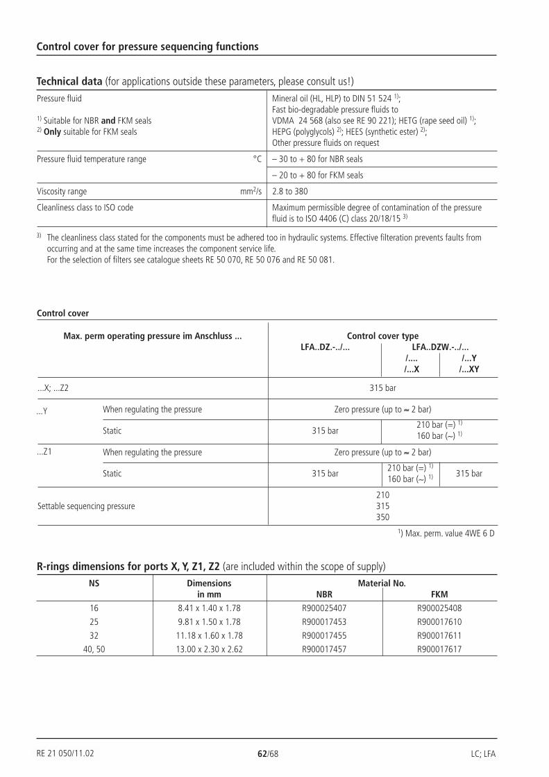
RE 21 050/02.99 62/68 LC; LFA
Control cover for pressure sequencing functions
Technical data (for applications outside these parameters, please consult us!)
Control cover
Pressure fluid Mineral oil (HL, HLP) to DIN 51 524 1);Fast bio-degradable pressure fluids to
1) Suitable for NBR and FKM seals VDMA 24 568 (also see RE 90 221); HETG (rape seed oil) 1);2) Only suitable for FKM seals HEPG (polyglycols) 2); HEES (synthetic ester) 2);
Other pressure fluids on request
Pressure fluid temperature range °C – 30 to + 80 for NBR seals
– 20 to + 80 for FKM seals
Viscosity range mm2/s 2.8 to 380
Cleanliness class to ISO code Maximum permissible degree of contamination of the pressurefluid is to ISO 4406 (C) class 20/18/15 3)
Max. perm operating pressure im Anschluss ... Control cover typeLFA..DZ.-../... LFA..DZW.-../...
/.... /...Y/...X /...XY
...X; ...Z2 315 bar
When regulating the pressure Zero pressure (up to ≈ 2 bar)
Static 315 bar
When regulating the pressure Zero pressure (up to ≈ 2 bar)
Static 315 bar 315 bar
210Settable sequencing pressure 315
350
210 bar (=) 1)
160 bar (∼) 1)
...Y
...Z1
210 bar (=) 1)
160 bar (∼) 1)
1) Max. perm. value 4WE 6 D
R-rings dimensions for ports X, Y, Z1, Z2 (are included within the scope of supply)
NS Dimensions Material No.in mm NBR FKM
16 8.41 x 1.40 x 1.78 R900025407 R900025408
25 9.81 x 1.50 x 1.78 R900017453 R900017610
32 11.18 x 1.60 x 1.78 R900017455 R900017611
40, 50 13.00 x 2.30 x 2.62 R900017457 R900017617
RE 21 050/11.02
3) The cleanliness class stated for the components must be adhered too in hydraulic systems. Effective filteration prevents faults fromoccurring and at the same time increases the component service life.For the selection of filters see catalogue sheets RE 50 070, RE 50 076 and RE 50 081.
LC; LFA 63/68 RE 21 050/02.99
Seal kits for cartridge valves and control covers
Seal kits for cartridge valvesType LC.. DB../... (NS 16 ... 50)
Seal kits for control coverType LFA.. /... (NS 16 ... 50)
Fixing screws (are included within the scope of supply)
S.H.C.S. to DIN 912-10.9
NS Qty. Dimensions Tightening torque in Nm
16 4 M 8 x 115 32
25 4 M 12 x 120 110
32 4 M 16 x 120 270
40 4 M 20 x 70 520
50 4 M 20 x 80 520
Orifice thread size
all built-in orifices: M6 tapered
Seal kit Material No.for NBR FKM
LC 16 DB..7X/.. R900313104 R900313107
LC 25 DB..7X/.. R900313105 R900313108
LC 32 DB..7X/.. R900313106 R900313109
LC 40 DB..7X/.. R900873022 R900873025
LC 50 DB..7X/.. R900873023 R900873026
Seal kit Material No.for LFA… 16 25 32 40 50
NBR FKM NBR FKM NBR FKM NBR FKM NBR FKM
R900860006 R900311540 R900311541 R900309378 R900312089...DZ......DZW...
RE 21 050/11.02
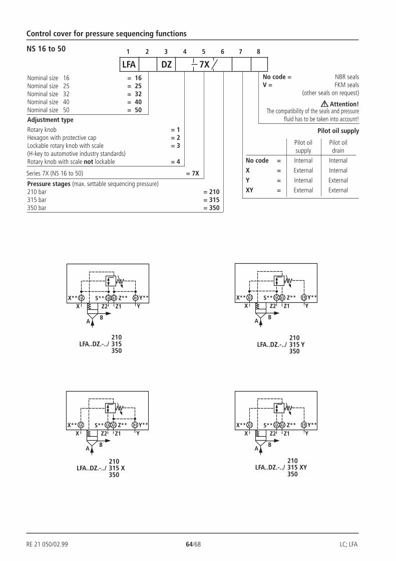
RE 21 050/02.99 64/68 LC; LFA
X
A
YZ1
B
Z2X** S** Z** Y**
X
A
YZ1
B
Z2X** S** Z** Y**
X
A
YZ1
B
Z2X** S** Z** Y**
X
A
YZ1
B
Z2X** S** Z** Y**
Control cover for pressure sequencing functions
1 2 3 4 5 6 7 8NS 16 to 50
No code = NBR sealsV = FKM seals
(other seals on request)
Attention!The compatibility of the seals and pressure
fluid has to be taken into account!
LFA DZ 7X
Adjustment type
Rotary knob = 1Hexagon with protective cap = 2Lockable rotary knob with scale = 3(H-key to automotive industry standards)Rotary knob with scale not lockable = 4
Nominal size 16 = 16Nominal size 25 = 25Nominal size 32 = 32Nominal size 40 = 40Nominal size 50 = 50
Series 7X (NS 16 to 50) = 7X
Pressure stages (max. settable sequencing pressure)210 bar = 210315 bar = 315350 bar = 350
Pilot oil supply
Pilot oil Pilot oilsupply drain
No code = Internal Internal
X = External Internal
Y = Internal External
XY = External External
210LFA..DZ.-../ 315
350
210LFA..DZ.-../ 315 X
350
210LFA..DZ.-../ 315 Y
350
210LFA..DZ.-../ 315 XY
350
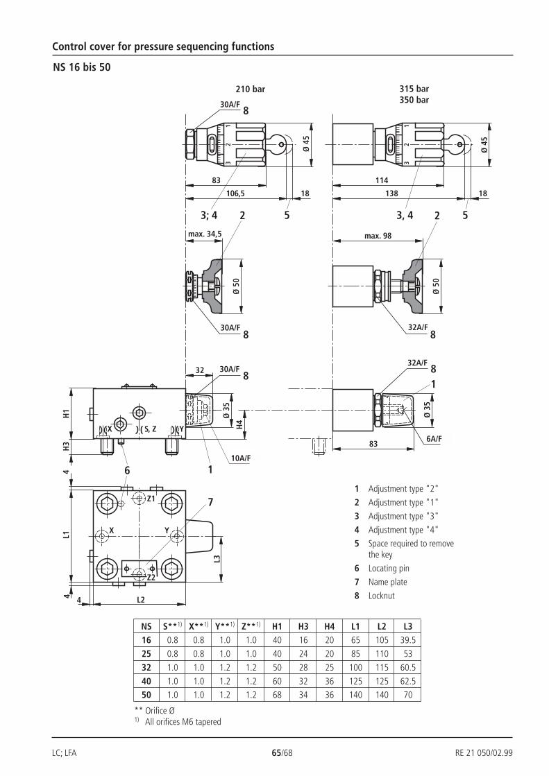
LC; LFA 65/68 RE 21 050/02.99
Z2
H1
H3
H4
X
6
7
32
Ø 3
51
32
YS, Z
13
2
4L1
4
4
X Y
Z1
1
SW30
max. 34,5Ø
50
SW308
2
SW308
83
106,5 18
Ø 4
5
3; 4 5
max. 98
Ø 5
0
SW328
2
114
138 18
3, 4 5
Ø 4
5
Ø 3
5
8SW32 8
83 SW6
1
SW10
L2
L3
NS 16 bis 50
Control cover for pressure sequencing functions
210 bar 315 bar350 bar
1 Adjustment type "2"
2 Adjustment type "1"
3 Adjustment type "3"
4 Adjustment type "4"
5 Space required to removethe key
6 Locating pin
7 Name plate
8 Locknut
NS S**1) X**1) Y**1) Z**1) H1 H3 H4 L1 L2 L316 0.8 0.8 1.0 1.0 40 16 20 65 105 39.5
25 0.8 0.8 1.0 1.0 40 24 20 85 110 53
32 1.0 1.0 1.2 1.2 50 28 25 100 115 60.5
40 1.0 1.0 1.2 1.2 60 32 36 125 125 62.5
50 1.0 1.0 1.2 1.2 68 34 36 140 140 70
** Orifice Ø1) All orifices M6 tapered
30A/F
30A/F
30A/F
10A/F
32A/F
32A/F
6A/F
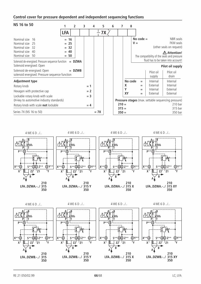
RE 21 050/02.99 66/68 LC; LFA
X
A
YZ1
B
P T
A Ba
Z2
X** S** Z** Y**
P**
X
A
YZ1
B
P T
A Ba
Z2
X** S** Z** Y**
P**
X
A
YZ1
B
P T
A Ba
Z2
X** S** Z** Y**
P**
X
A
YZ1
B
P T
A Ba
Z2
X** S** Z** Y**
P**
X
A
YZ1
B
P T
A Ba
Z2
X** S** Z** Y**
P**
X
A
YZ1
B
P T
A Ba
Z2
X** S** Z** Y**
P**
X
A
YZ1
B
P T
A Ba
Z2
X** S** Z** Y**
P**
X
A
YZ1
B
P T
A Ba
Z2
X** S** Z** Y**
P**
Control cover for pressure dependent and independent sequencing functions
1 2 3 4 5 6 7 8NS 16 to 50
No code = NBR sealsV = FKM seals
(other seals on request)
Attention!The compatibility of the seals and pressure
fluid has to be taken into account!
LFA 7X
Adjustment typeRotary knob = 1
Hexagon with protective cap = 2
Lockable rotary knob with scale = 3(H-key to automotive industry standards)
Rotary knob with scale not lockable = 4
Nominal size 16 = 16Nominal size 25 = 25Nominal size 32 = 32Nominal size 40 = 40Nominal size 50 = 50
Series 7X (NS 16 to 50) = 7X
Pressure stages (max. settable sequencing pressure)210 = 210 bar315 = 315 bar350 = 350 bar
Pilot oil supply
Pilot oil Pilot oilsupply drain
No code = Internal InternalX = External InternalY = Internal ExternalXY = External External
Solenoid de-energised: Pressure sequence function = DZWASolenoid energised: Open
Solenoid de-energised: Open = DZWBsolenoid energised: Pressure sequence function
4 WE 6 D ../..
210LFA..DZWA.-../ 315
350
210LFA..DZWB.-../ 315
350
210LFA..DZWA.-../ 315 Y
350
210LFA..DZWA.-../ 315 X
350
210LFA..DZWA.-../ 315 XY
350
210LFA..DZWB.-../ 315 Y
350
210LFA..DZWB.-../ 315 X
350
210LFA..DZWB.-../ 315 XY
350
4 WE 6 D ../.. 4 WE 6 D ../.. 4 WE 6 D ../..
4 WE 6 D ../.. 4 WE 6 D ../.. 4 WE 6 D ../.. 4 WE 6 D ../..
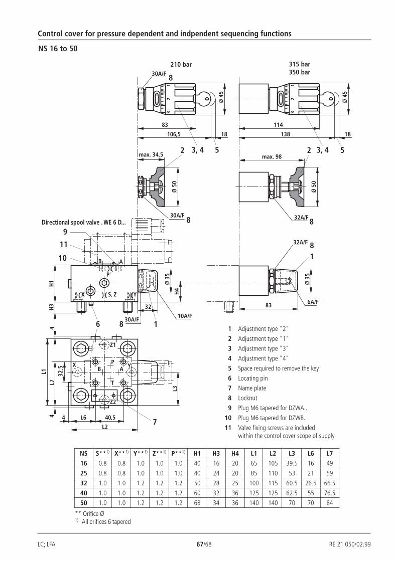
LC; LFA 67/68 RE 21 050/02.99
Z2
H1
H3
H4
X
6
7
32
Ø 3
51
32
YS, Z1
32
4L1
4
4
X Y
Z1
1SW30
max. 34,5
Ø 5
0
SW308
2
SW308
83
106,5 18
Ø 4
5
3, 4 5max. 98
Ø 5
0
SW328
2
114
138 18
3, 4 5
Ø 4
5
Ø 3
5
8
SW32 8
83 SW6
1
SW10
P
B A
B AP
T
9
11
10
L6 40,5
32,5
L3
L2
L7NS 16 to 50
Control cover for pressure dependent and indpendent sequencing functions
210 bar 315 bar350 bar
NS S**1) X**1) Y**1) Z**1) P**1) H1 H3 H4 L1 L2 L3 L6 L716 0.8 0.8 1.0 1.0 1.0 40 16 20 65 105 39.5 16 49
25 0.8 0.8 1.0 1.0 1.0 40 24 20 85 110 53 21 59
32 1.0 1.0 1.2 1.2 1.2 50 28 25 100 115 60.5 26.5 66.5
40 1.0 1.0 1.2 1.2 1.2 60 32 36 125 125 62.5 55 76.5
50 1.0 1.0 1.2 1.2 1.2 68 34 36 140 140 70 70 84
** Orifice Ø1) All orifices 6 tapered
1 Adjustment type "2"
2 Adjustment type "1"
3 Adjustment type "3"
4 Adjustment type "4"
5 Space required to remove the key
6 Locating pin
7 Name plate
8 Locknut
9 Plug M6 tapered for DZWA..
10 Plug M6 tapered for DZWB..
11 Valve fixing screws are includedwithin the control cover scope of supply
Directional spool valve . WE 6 D...
30A/F
30A/F
30A/F10A/F
32A/F
32A/F
6A/F
RE 21 050/02.03 68/68 LC; LFA
Bosch Rexroth AGIndustrial Hydraulics
D-97813 Lohr am MainZum Eisengießer 1 • D-97816 Lohr am MainTelefon 0 93 52 / 18-0Telefax 0 93 52 / 18-23 58 • Telex 6 89 418-0eMail [email protected] www.boschrexroth.de
The data specified above only serves to describethe product. No statements concerning a certaincondition or suitability for a certain applicationcan be derived from our information.The details stated do not release you from theresponsibility for carrying out your ownassessment and verification. It must beremembered that our products are subject to anatural process of wear and ageing.
Bosch Rexroth Limited
Cromwell Road, St Neots,Cambs, PE19 2ESTel: 0 14 80/22 32 56Fax: 0 14 80/21 90 52E-mail: [email protected]
Notes