vertex lite collar
TRANSCRIPT

VERTEX Lite Collar
Version: 1.1
Last Change: 22.07.2016
User Manual

All rights reserved. No parts of this work may be reproduced in any form or by any means - graphic, electronic, ormechanical, including photocopying, recording, taping, or information storage and retrieval systems - without thewritten permission of the publisher.
Products that are referred to in this document may be either trademarks and/or registered trademarks of therespective owners. The publisher and the author make no claim to these trademarks.
While every precaution has been taken in the preparation of this document, the publisher and the author assume noresponsibility for errors or omissions, or for damages resulting from the use of information contained in thisdocument or from the use of programs and source code that may accompany it. In no event shall the publisher andthe author be liable for any loss of profit or any other commercial damage caused or alleged to have been causeddirectly or indirectly by this document.
VERTEX Lite Collar
© 2016 VECTRONIC Aerospace GmbH
User Manual
24.06.2016 Marcel Butz
Marcel Butz
Robert Schulte
Robert Schulte
08.07.2016
15.07.2016
15.07.2016

Document Change Record

VERTEX Lite Collar4
Table of Contents
...............................................................................................................71 Product overview
...............................................................................................................82 Fast guide to deploy the collar
...............................................................................................................93 The Vertex Lite collar system
...................................................................................................................... 93.1 The Collar
...................................................................................................................... 103.2 GPS Receiver
...................................................................................................................... 113.3 VHF Beacon
...................................................................................................................... 123.4 Mortality Sensor
...................................................................................................................... 123.5 Activity Sensor (Acceleration)
...................................................................................................................... 133.6 Drop Off
...................................................................................................................... 143.7 Communication options
...................................................................................................... 14Globalstar Communication 3.7.1
...................................................................................................... 15Iridium Communication 3.7.2
...................................................................................................... 16GSM Communication 3.7.3
...................................................................................................................... 183.8 Software
...................................................................................................................... 183.9 Data Format
...................................................................................................... 19List of files and extensions used 3.9.1
...............................................................................................................204 System Set-up
...................................................................................................................... 214.1 Installation of the user-software GPS Plus X
...................................................................................................................... 214.2 Collar Registration
...................................................................................................................... 224.3 Registration of the USB Remote Stick

5Contents
5
...............................................................................................................255 Direct Collar Communication (USB
Remote Stick)
...................................................................................................................... 265.1 USB Remote Stick (Main node)
...................................................................................................... 27Collar Contact (general) 5.1.1
...................................................................................................... 28Testing several collars 5.1.2
...................................................................................................................... 285.2 Collar Main Tree
...................................................................................................... 29Information 5.2.1
........................................................................................................... 30Telemetry5.2.1.1
........................................................................................................... 33GPS Monitor5.2.1.2
........................................................................................................... 34Info File5.2.1.3
...................................................................................................... 36Configuration 5.2.2
........................................................................................................... 36User Configuration5.2.2.1
........................................................................................................... 40Setting the time5.2.2.2
........................................................................................................... 41Firmware Upload5.2.2.3
...................................................................................................... 42Schedules 5.2.3
........................................................................................................... 43GPS schedule5.2.3.1
........................................................................................................... 45VHF Beacon Schedule5.2.3.2
........................................................................................................... 46VHF Beacon & GPS Beacon Schedule FilesUpload
5.2.3.3
...................................................................................................... 47Collected Data 5.2.4
........................................................................................................... 49Position5.2.4.1
........................................................................................................... 53Activity5.2.4.2
........................................................................................................... 54Mortality5.2.4.3
...............................................................................................................566 Remote Collar (Communication)
VERTEX Lite Collar6
...................................................................................................................... 566.1 Remote User Configuration
...................................................................................................................... 596.2 Remote GPS Schedule
...................................................................................................................... 596.3 Remote Beacon Schedule
...............................................................................................................607 Calculate Collar Lifetime
...............................................................................................................628 Test the collar
...............................................................................................................629 Attach the collar to the animal
...............................................................................................................6310 Battery options
...............................................................................................................6411 Changing of battery pack
...................................................................................................................... 6511.1 Oval Collar
...................................................................................................................... 6611.2 Round Collar, standard battery pack
...................................................................................................................... 6711.3 Round Collar, curved battery pack
...............................................................................................................6912 The Vertex Lite collar with integrated UHF
ID-Tag
...............................................................................................................7013 Specification
...................................................................................................................... 7013.1 Environmental specification for the collar
...................................................................................................................... 7113.2 Declarations of Conformity
...................................................................................................................... 7313.3 Certificates
Product overview 7
© 2016 VECTRONIC Aerospace GmbH
1 Product overview
The VERTEX Lite Collar generates GPS, mortality and activity data. It sends regularGPS and mortality updates via GSM / Globalstar / Iridium communication.
Most important features:
Unlimited GPS localizations per day
3-axis accelerometer to measure activity
User definable Beacon and GPS settings
On board flash memory
Drop Off (on demand)
24/7 mortality observation and notification
Ambient temperature data
Any Battery 1C- 7D
Field replaceable Batteries
Communication options:
Globalstar (One-way communication: enables data download)
Iridium (Two-way communication: enables data download and upload of new
commands and schedules)
GSM (Two-way communication: enables data download and upload of new
commands and schedules)
The VERTEX Lite Collars can also host an UHF ID Tag to be used in interaction studiesin combination with a VERTEX Plus collar.
All data is stored on the flash memory onboard the collar. GPS locations, temperatureand event data are send using either Globalstar / Iridium / GSM communication. Afterretrieval of the collar data can be downloaded using the USB Remote Stick (wirelessdata communication with a few meters range).
Globalstar collars can be reconfigured with the USB Remote Stick, whereas Iridium and

VERTEX Lite Collar8
© 2016 VECTRONIC Aerospace GmbH
GSM collars can also be reconfigured remotely using the two-way communication:
GPS schedule and settings
Beacon schedule and settings
Mortality period
Iridium / GSM settings
2 Fast guide to deploy the collar
The collars come thoroughly tested and fully programmed according to your instructions.Nevertheless we recommend to setup your GPS Plus X (software) system beforehand,check the programmed settings and test the collars:
1. Make yourself familiar with the collar [(de)activation magnet should be attached]
2. Setup your GPS Plus X software system (for further information please refer to theGPS Plus X software manual)
3. Register the collars
4. Check / change the settings (using the USB Remote Stick)
5. Check Drop Off configuration and lifetime (please refer to GPS Plus Drop OffManager or Info Files provided with the collar)
6. Make a lifetime calculation (optional)
7. Test the collars
7.1 Remove the (de)activation magnet (not the Drop Off magnet!)
7.2 Place them preferably outdoors with clear view to the sky (Do not place thecollars too tightly as their signals might interfere and effect the testing)
7.3 Listen for the VHF beacon signal (Check settings for frequency and patterntypes beforehand)
7.4 Wait for incoming messages (Check for expected time frames first, plan yourtesting to include several data transmission windows)
7.5 Process incoming data and check signal quality etc.

Fast guide to deploy the collar 9
© 2016 VECTRONIC Aerospace GmbH
7.6 (GSM / Iridium: send reconfiguration commands remotely)
7.7 Deactivate them by reattaching the magnet
Do not trigger the Drop Off! It can only be used once!
8. Check and optionally alter the settings to field configuration
9. Deploy the collar (NOTE: remove all magnets and cut the overhanging belting tominimize the risk to injure or handicap the animal)
The steps of this list will be explained more detailed in the following chapters.
3 The Vertex Lite collar system
The VERTEX Lite Collar uses a two housing design, one electronic and one battery unit.The VHF beacon antenna is integrated into the belt. There are different collar designs,housings and battery sizes to fit it to each species.
follow the links to the subtopics explaining the collar and its system:
The collar
GPS Receiver
VHF Beacon
Mortality Sensor
Communication options
Software
Data Format
3.1 The Collar
The VERTEX Lite Collar consists of the following components:

VERTEX Lite Collar10
© 2016 VECTRONIC Aerospace GmbH
Figure 1: VERTEX Lite Collar
3.2 GPS Receiver
The collar contains a standard GPS receiver with an accuracy of roughly 95% within 10meters. The actual accuracy depends on many factors such as terrain, satellitereception and time to conduct a fix (GPS position). Most fixes will be far more accurate.
A GPS schedule defines when GPS positions will be recorded. Programming of theGPS schedule is very flexible and easy.
Once activated the receiver listens for satellite data and collects ephemerides data toconduct a GPS location. The maximum listening period is 180s but it will stop listeningbefore that if
a) it receives a validated fix of highest quality
b) it gets several decent quality signals
c) it gets no satellite connection at all
Each GPS position is stored with following data:
The Vertex Lite collar system 11
© 2016 VECTRONIC Aerospace GmbH
- UTC (universal time coordinated) date and time
- GPS coordinates (Latitude, Longitude and Height)
- Dilution of Precision (DOP) and navigation status as quality information as well asnumber of satellites used for positioning.
GPS data can be exported via the user software GPS Plus X to ASCII, Spreadsheet,DBase, GPS Exchange, Google Earth and BioTelemetry eXchange format. You caneasily import the data into Google Earth via kml.file to visualise GPS positions.
3.3 VHF Beacon
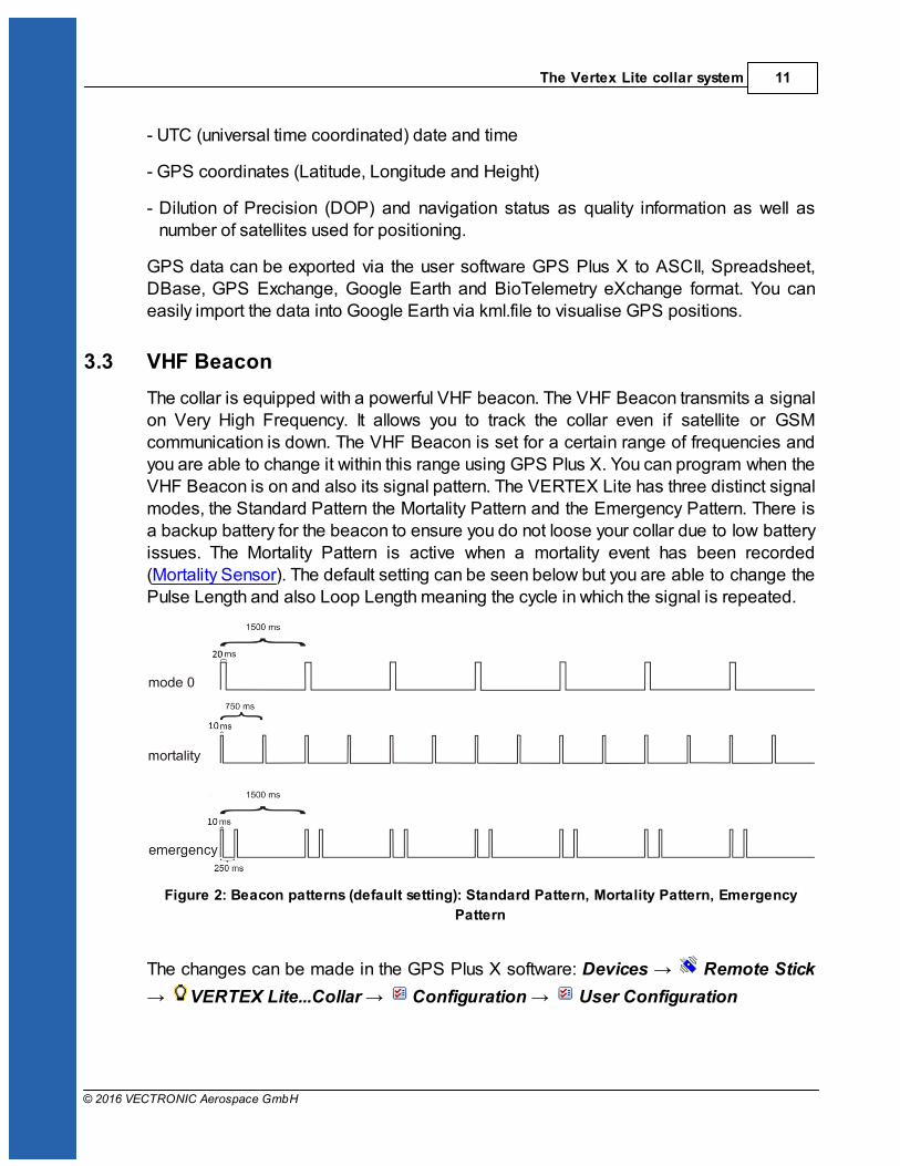
The collar is equipped with a powerful VHF beacon. The VHF Beacon transmits a signalon Very High Frequency. It allows you to track the collar even if satellite or GSMcommunication is down. The VHF Beacon is set for a certain range of frequencies andyou are able to change it within this range using GPS Plus X. You can program when theVHF Beacon is on and also its signal pattern. The VERTEX Lite has three distinct signalmodes, the Standard Pattern the Mortality Pattern and the Emergency Pattern. There isa backup battery for the beacon to ensure you do not loose your collar due to low batteryissues. The Mortality Pattern is active when a mortality event has been recorded(Mortality Sensor). The default setting can be seen below but you are able to change thePulse Length and also Loop Length meaning the cycle in which the signal is repeated.
Figure 2: Beacon patterns (default setting): Standard Pattern, Mortality Pattern, Emergency
Pattern
The changes can be made in the GPS Plus X software: Devices Remote Stick
VERTEX Lite...Collar Configuration User Configuration

VERTEX Lite Collar12
© 2016 VECTRONIC Aerospace GmbH
3.4 Mortality Sensor
The mortality sensor measures the activity of the animal. If no movement (activity) isdetected for a user-defined period (e.g. 24 hours), a mortality event is triggered. Themortality period is user-definable and can be set up to 140 hours. When a mortalityevent is detected, the collar:
- Switches the VHF Beacon pattern to the Mortality Mode
- Sends out a mortality event message via Globalstar / Iridium / GSM
communication
- Conducts unscheduled GPS fixes each 30 minutes for six hours before it returns
to the programmed schedule
- Sends messages according to set communication patterns
The collar will end the mortality mode if the sensor registers repetitive activity for roughly20 minutes.
NOTE: The mortality period should be adapted to the behavior of the collared animal so
you get no false events (e.g. lions with a very long passive phase should get a longermortality period as for example roe deer with a distinct but short activity pattern). Thedefault setting is 24h which has been used successfully in a variety of studies.
3.5 Activity Sensor (Acceleration)
The VERTEX Lite Collar is equipped with a Basic Activity sensor. The data are stored
in the on board flash memory. The sensor records average data every 300 seconds.You can analyze relative activity based on right-left, up-down and forward- backwardmovement.
The Vertex Lite collar system 13
© 2016 VECTRONIC Aerospace GmbH
Figure 3: Directions of the three activity axes
3.6 Drop Off
Drop Offs allow retrieving the collar without having to recapture the animal.
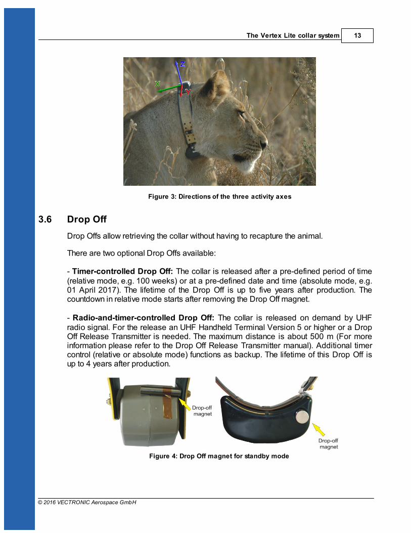
There are two optional Drop Offs available: - Timer-controlled Drop Off: The collar is released after a pre-defined period of time(relative mode, e.g. 100 weeks) or at a pre-defined date and time (absolute mode, e.g.01 April 2017). The lifetime of the Drop Off is up to five years after production. Thecountdown in relative mode starts after removing the Drop Off magnet.
- Radio-and-timer-controlled Drop Off: The collar is released on demand by UHFradio signal. For the release an UHF Handheld Terminal Version 5 or higher or a DropOff Release Transmitter is needed. The maximum distance is about 500 m (For moreinformation please refer to the Drop Off Release Transmitter manual). Additional timercontrol (relative or absolute mode) functions as backup. The lifetime of this Drop Off isup to 4 years after production.
Figure 4: Drop Off magnet for standby mode

VERTEX Lite Collar14
© 2016 VECTRONIC Aerospace GmbH
Figure 5: Drop Off release sites, magnet removed
3.7 Communication options
The VERTEX Lite Collar is available as Iridium, Globalstar or GSM version. Follow thelink to your chosen configuration for information about the respective communicationsystem.
Iridium
Globalstar
GSM
3.7.1 Globalstar Communication
Globalstar offers a one-way communication means you receive GPS and mortality data,transmitted by the collar. The system provides a broad but space and time restrictedcoverage network.
Figure 6: Globalstar Coverage 2015
The Vertex Lite collar system 15
© 2016 VECTRONIC Aerospace GmbH
Each position data is sent by the collar (1-2 Fix per message with minimum pause of30min between each message). Data is send out several times to increasetransmission probability but data reception is not confirmed by the satellites. Thesatellite sends its data to a base station on ground which forwards it via web to oursystem. It is possible that transmissions are blocked (e.g. thick canopy, bad angletowards ski etc.) and do not reach the satellites and thereby you. Most often the data willget through and to our system from which your GPS Plus X software will automaticallydownload the data. You can also get the data as email forwarding when the Httpdownload is unsuitable for whatever reason. You can get the full dataset by downloadingit after collar retrieving with the USB Remote stick.
NOTE: You can set a skip count to exclude some fixes from the data satellite
transmission pool to receive fewer messages and thereby extend the collar lifetime (e.g.skip count 2 means sending only every second fix, all data remains stored on the collartoo). Please keep in mind that you cannot alter the settings once the collar is deployed.A skip count could potentially drastically reduce the collar messages you receive up togetting no data (e.g. high GPS skip count in a very unsuitable habitat such as denseforest). For further information please contact our customer service.
3.7.2 Iridium Communication
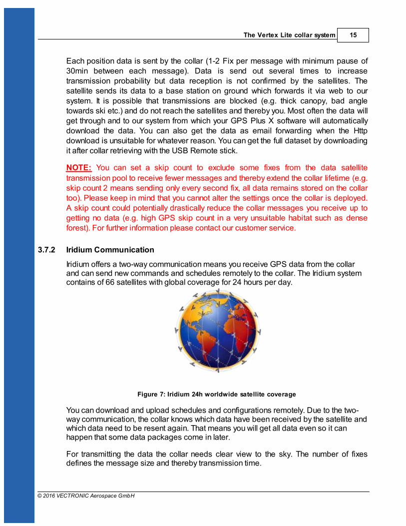
Iridium offers a two-way communication means you receive GPS data from the collarand can send new commands and schedules remotely to the collar. The Iridium systemcontains of 66 satellites with global coverage for 24 hours per day.
Figure 7: Iridium 24h worldwide satellite coverage
You can download and upload schedules and configurations remotely. Due to the two-way communication, the collar knows which data have been received by the satellite andwhich data need to be resent again. That means you will get all data even so it canhappen that some data packages come in later.
For transmitting the data the collar needs clear view to the sky. The number of fixesdefines the message size and thereby transmission time.
VERTEX Lite Collar16
© 2016 VECTRONIC Aerospace GmbH
How it works: The system uses 3 message blocks whereas the first block can contain 1-4 GPS fixes,the second block additional 8 at most and the third and last block additional 6. In total,18 fixes (in one big message) can be transmitted in one transmission window. Theremaining space within a block will be filled with placeholder data, so the message won'tget smaller if you choose less than 4 (1-3), 12 (5-11), 18 (13-17). Please note that the collar “listens” for incoming commands whenever it has send outdata only, meaning you have distinct communication windows based on the scheduleused and transmission made (e.g. hourly fixes with 4 fixes a message result in onemessage every 4 hours). Data are sent to our GPS Plus X main server and provided toyour GPS Plus X software for HTTP download or email forwarding / reception.
NOTE: It highly depends on species and terrain how many fixes the collar should
transmit in one message. In most cases we recommend to start with 4 fixes permessage (default settings) and to increase the number after deployment when you seedata is incoming regularly. An unsuitable setting (e.g. 18 fixes / message in denseforest) could result in high rate of failed transmissions or in worst case in loosing contactto the collar.
NOTE: You can set a skip count to exclude some fixes from the data satellite
transmission pool to receive fewer messages and thereby extend the battery lifetime(e.g. skip count 2 means sending only every third fix, all data will be stored in the collartoo). A skip count reduces the collar messages you receive (High GPS skip count in avery unsuitable habitat such as dense forest may result in loosing contact with the collar).
3.7.3 GSM Communication
GSM is using the SMS service of mobile phone providers. The GSM communication isa two-way communication, means you receive GPS data from the collar and can sendnew commands and schedules remotely to the collar. GPS and mortality data will besent automatically via SMS to the defined phone number. If you wish sending newcommands or schedules remotely, please contact our customer service. It is onlypossible to communicate with the collar within GSM provider coverage.

The Vertex Lite collar system 17
© 2016 VECTRONIC Aerospace GmbH
Figure 8: GSM Communication
For collar usage within Europe we provide GSM collars with VECTRONIC SIM chips
so you do not have to take care about provider administration. VECTRONIC SIM chips
are soldered in the electronic housing and highly reliable in all kinds of environmentalconditions (heat, cold, humidity, vibrations, shock). How it works:One message transmitted via GSM/GPRS contains 8 GPS positions per default.Messages will be send to VECTRONIC ground-station and from there downloaded viaHTTP to GPS Plus X software. All GPS Data, irrespective of transmitting, will be storedin the non-volatile on-board-memory. Data not transmitted via GSM can be downloadedvia UHF radio link (if available) or via USB Remote Stick after the collar has beenretrieved.
For collar usage in Africa, Asia or Nord- and South America you may choose your ownmobile phone provider and provide Micro SIM cards on your own. Here, messagetransmitted via GSM contains 7 GPS positions per default. It is recommended havingyour own GSM Ground station if you using your GSM collars with your own SIM cards.
VERTEX Lite Collar18
© 2016 VECTRONIC Aerospace GmbH
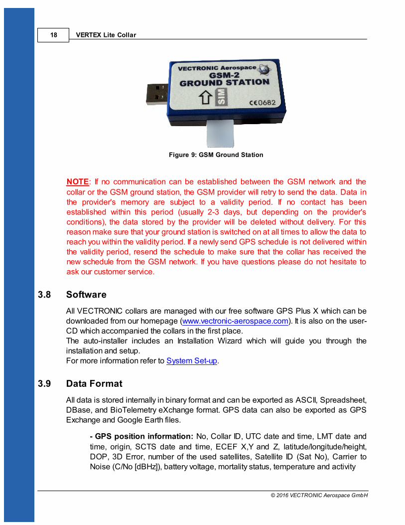
Figure 9: GSM Ground Station
NOTE: If no communication can be established between the GSM network and the
collar or the GSM ground station, the GSM provider will retry to send the data. Data inthe provider's memory are subject to a validity period. If no contact has beenestablished within this period (usually 2-3 days, but depending on the provider'sconditions), the data stored by the provider will be deleted without delivery. For thisreason make sure that your ground station is switched on at all times to allow the data toreach you within the validity period. If a newly send GPS schedule is not delivered withinthe validity period, resend the schedule to make sure that the collar has received thenew schedule from the GSM network. If you have questions please do not hesitate toask our customer service.
3.8 Software
All VECTRONIC collars are managed with our free software GPS Plus X which can bedownloaded from our homepage (www.vectronic-aerospace.com). It is also on the user-CD which accompanied the collars in the first place.The auto-installer includes an Installation Wizard which will guide you through theinstallation and setup. For more information refer to System Set-up.
3.9 Data Format
All data is stored internally in binary format and can be exported as ASCII, Spreadsheet,DBase, and BioTelemetry eXchange format. GPS data can also be exported as GPSExchange and Google Earth files.
- GPS position information: No, Collar ID, UTC date and time, LMT date and
time, origin, SCTS date and time, ECEF X,Y and Z, latitude/longitude/height,DOP, 3D Error, number of the used satellites, Satellite ID (Sat No), Carrier toNoise (C/No [dBHz]), battery voltage, mortality status, temperature and activity

The Vertex Lite collar system 19
© 2016 VECTRONIC Aerospace GmbH
- Temperature: Temperature data are stored and transmitted with the GPS
position data.
- Mortality information: Date and time of a mortality event based on the activity
of the animal. The GPS Plus X software stores the received mortality message inthe data base.
- Activity: records averaged data every 300 seconds on 3-axis (X, Y, Z). So,
you can analyze relative activity based on right- left, up- down and forward-backward movement. Activity data can be downloaded after collar retrieving.(Format: adf. or adf3.)
3.9.1 List of files and extensions used
Download files
.GDF GPS Data File Binary coded GPS fix data from the collar includingmain battery voltage, VHF beacon battery voltage, andtemperature. The file name consists of the collarnumber and the time stamp of the file creation codedas “yyyymmddhhmmss”.
Export files
.GDF GPS Data File Binary coded GPS fix data from the collar includingmain battery voltage, VHF beacon battery voltage, andtemperature. The file name consists of the collarnumber and the time stamp of the file creation codedas “yyyymmddhhmmss”.
.TXT ASCII Visually readable equidistant table, compatible to con-ventional text editors and spreadsheets
.CSV Spreadsheet Computer readable table, compatible to conventionaltext editors and spreadsheets
.DBF DBase Table Database format, compatible to conventional spread-sheets and most text editors
.GPXGPS Exchange
FormatFile for data exchange with GPS devices
.KML KML Google Earth file to display tracks, points of interest…

VERTEX Lite Collar20
© 2016 VECTRONIC Aerospace GmbH
.KMZ KMZ Zipped Google Earth file
.BTXBioTelemetry
eXchangeVECTRONIC-defined XML-format
.GDX
.ADF
.ADF3
GPS Data eXchange Is an XML format defined by VECTRONIC Aerospace,which will make it easier to exchange acquired dataover system boundaries. It is an internal format of GPSPlus X and can also be used as import format.
2-axis Activity Data File
3-axis Activity Data File
Upload files
.vbsf Beacon Schedule File VHF beacon schedule of the Survey collar
.vgsf GPS Schedule File GPS schedule of the Survey collar
Hardware information files
.CCF Collar ConfigurationFile
contains the configuration (schedules, communicationconfiguration, activity mode) of the collar
.bin Collar Firmware File contains firmware for Survey collars
.key Collar Key File contains a key for one collar, needed to register thecollar in the GPS Plus X and to manage its data
.txt Collar Info File contains all information on the collar configuration
4 System Set-up
All VECTRONIC collars come completely programmed according to your specifications.You can change the configuration yourself with the GPS Plus X user software and thewireless USB Remote Stick.

System Set-up 21
© 2016 VECTRONIC Aerospace GmbH
This section will guide you through all steps for getting started whereas you will
find a more detailed description for all features in the GPS Plus X software Manual.
Firstly: Installation of the user-software GPS Plus X
Secondly: Collar Registration
Thirdly: Registration of the USB Remote Stick
4.1 Installation of the user-software GPS Plus X
The Installation wizard will guide you through the process of installing GPS Plus X. Youcan install the software from the User-CD (auto-run or manual from the folder / software /GPS Plus X) or download the latest version from our website: www.vectronic-aerospace.com.
The installation procedure will ask you for a destination directory and suggest a defaultdirectory. You can now decide whether you want to install one of the following softwarepackages (list might vary with program versions):
User Interface: Collar communication and configuration
Data Storage Service: Data management, visualization and export
Data Collector Service: Data reception and distribution
Color Selector: Tool to select a color for the belt of your collar
TeamViewerQS VAS: Tool for remote desktop support
GPS Plus X Manual: integrated Manual
By default, GPS Plus X will be configured to run on a single computer. Please refer tothe GPS Plus X software manual for further details on GPS Plus X network set-up.
4.2 Collar Registration
To be able to configure the collars and to process data and messages with the GPS Plus
X software, you need to register the collars. The keys for each collar will be provided withthe User-CD which came with the collars in the first place.
For registering the collar, please go to the Configuration tree in GPS Plus X and
select Collars

VERTEX Lite Collar22
© 2016 VECTRONIC Aerospace GmbH
Figure 10: Collar Properties Editor
In the appearing window “Collar List”, press to add a new collar to the list. Afterclicking on the button, the Collar Properties Editor appears. To register a collar, click
. An open file dialog will open and you can select the collar registration key forthe collar (to be found in the folder Resources\Collar and Drop Off Keys).
If you add the details before registering the collar, the registration status of the collar willbe invalid. After registration, the entry of the corresponding collar will change from invalidto valid. For more information on collar registration, refer to the GPS Plus X Manual.
After you have registered the collar, you will be able to communicate with the collar usingthe USB Remote Stick.
4.3 Registration of the USB Remote Stick
To be able to configure the collars and to process data and messages with the GPSPlus X software, please connect the USB Remote Stick to your PC while GPS Plus X is
System Set-up 23
© 2016 VECTRONIC Aerospace GmbH
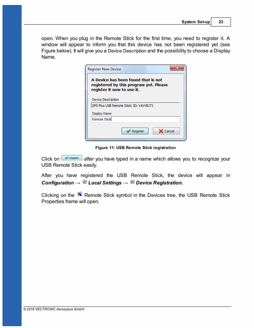
open. When you plug in the Remote Stick for the first time, you need to register it. Awindow will appear to inform you that this device has not been registered yet (seeFigure below). It will give you a Device Description and the possibility to choose a DisplayName.
Figure 11: USB Remote Stick registration
Click on after you have typed in a name which allows you to recognize yourUSB Remote Stick easily.
After you have registered the USB Remote Stick, the device will appear in
Configuration Local Settings Device Registration.
Clicking on the Remote Stick symbol in the Devices tree, the USB Remote StickProperties frame will open.
VERTEX Lite Collar24
© 2016 VECTRONIC Aerospace GmbH
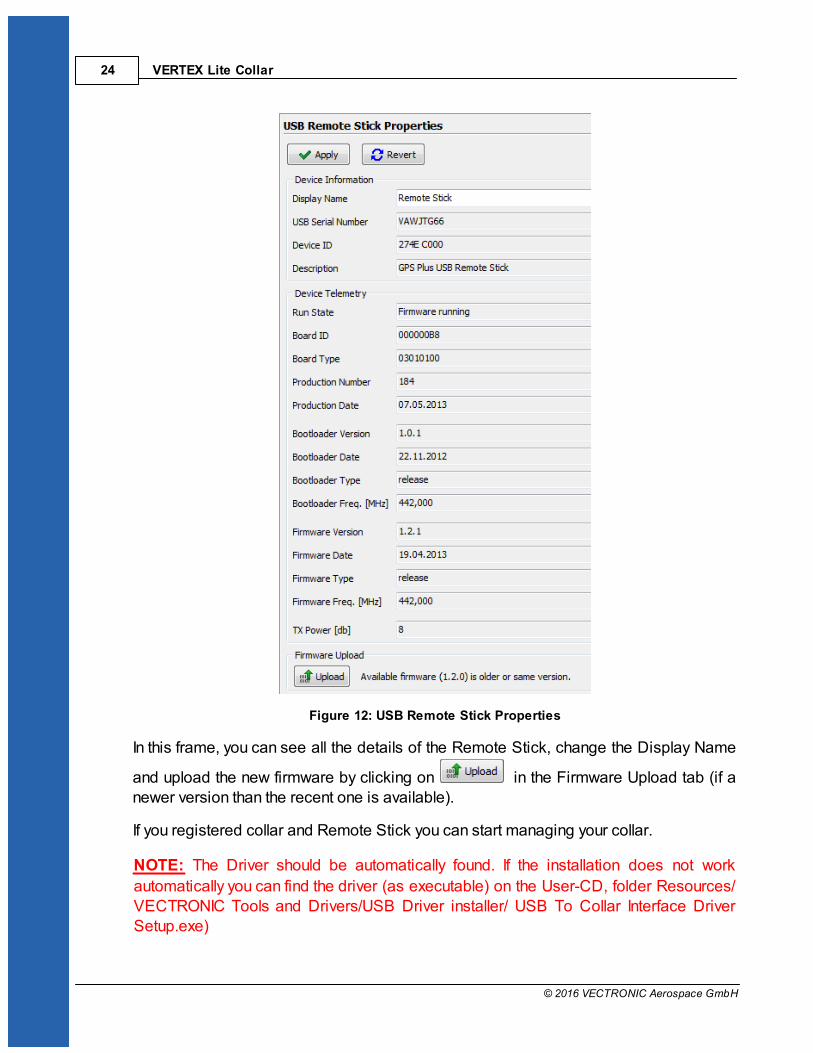
Figure 12: USB Remote Stick Properties
In this frame, you can see all the details of the Remote Stick, change the Display Name
and upload the new firmware by clicking on in the Firmware Upload tab (if anewer version than the recent one is available).
If you registered collar and Remote Stick you can start managing your collar.
NOTE: The Driver should be automatically found. If the installation does not work
automatically you can find the driver (as executable) on the User-CD, folder Resources/VECTRONIC Tools and Drivers/USB Driver installer/ USB To Collar Interface DriverSetup.exe)

System Set-up 25
© 2016 VECTRONIC Aerospace GmbH
5 Direct Collar Communication (USB Remote Stick)
All VERTEX Lite Collars can be accessed via USB Remote Stick, a small device youneed to attach to the USB port on your computer.
Figure 13: USB Remote Stick front side (top) and back side (bottom)
Combined with the Windows based GPS Plus X software, this is a tool to uploadconfigurations, schedules and to download measurement data or show collar statusinformation. You need to make the configurations while the USB Remote Stick isattached to your computer and the collar is in a range of about 0.5 – 2.0 meters awayfrom the stick. You are able to communicate with several collars simultaneously andconfigure them parallel as well.
After you set-up your system you are able to communicate with the collar.
The actual collar configuration is done in the node “Devices”. It is divided into “RemoteCollars” for remote configuration (Iridium, GSM communication only) and on-site
communication using the USB Remote Stick.
VERTEX Lite Collar26
© 2016 VECTRONIC Aerospace GmbH
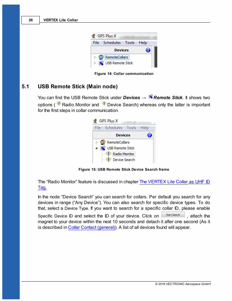
Figure 14: Collar communication
5.1 USB Remote Stick (Main node)
You can find the USB Remote Stick under Devices Remote Stick. It shows two
options ( Radio Monitor and Device Search) whereas only the latter is importantfor the first steps in collar communication.
Figure 15: USB Remote Stick Device Search frame
The “Radio Monitor” feature is discussed in chapter The VERTEX Lite Collar as UHF IDTag.
In the node “Device Search” you can search for collars. Per default you search for anydevices in range (“Any Device”). You can also search for specific device types. To dothat, select a Device Type. If you want to search for a specific collar ID, please enable
Specific Device ID and select the ID of your device. Click on , attach themagnet to your device within the next 10 seconds and detach it after one second (As itis described in Collar Contact (general)). A list of all devices found will appear.

Direct Collar Communication (USB Remote Stick) 27
© 2016 VECTRONIC Aerospace GmbH
Figure 16: USB Remote Stick Device Search frame
Once ensured that the devices work and can be contacted by the software, collarcommunication and reconfiguration can be started.
5.1.1 Collar Contact (general)
To configure the collar, make sure that the magnet is detached from the collar so that itis able to receive configurations and send data. Whenever you click on a node in theDevices tree (Information, Configuration, Schedules or Collected data), a notificationmessage will appear. In this message, you are requested to attach the magnet to thecollar and detach it after one second. You can abort the connecting process by clickingthe corresponding button or the ESC button on your keyboard.
Figure 17: Notification window which appears when you send out a command of any kind.
It happens that the communication cannot be established showing different errormessages. Most often it will be enough to redo it. The communication works best whenthere is a clear path between collar and USB Remote Stick without obstacles whichmight interfere with the signals.
Recommendation: A simply trick to further fasten the process is to place the magnet
upside-down on the connection port of the collar while working with it instead ofreattaching it securely with the Velcro tape each time.
VERTEX Lite Collar28
© 2016 VECTRONIC Aerospace GmbH
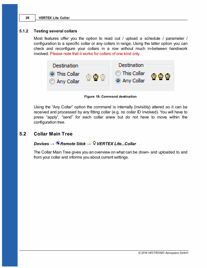
5.1.2 Testing several collars
Most features offer you the option to read out / upload a schedule / parameter /configuration to a specific collar or any collars in range. Using the latter option you cancheck and reconfigure your collars in a row without much in-between handiworkinvolved. Please note that it works for collars of one kind only.
Figure 18: Command destination
Using the “Any Collar” option the command is internally (invisibly) altered so it can bereceived and processed by any fitting collar (e.g. no collar ID involved). You will have topress “apply”, “send” for each collar anew but do not have to move within theconfiguration tree.
5.2 Collar Main Tree
Devices Remote Stick VERTEX Lite...Collar
The Collar Main Tree gives you an overview on what can be down- and uploaded to andfrom your collar and informs you about current settings.

Direct Collar Communication (USB Remote Stick) 29
© 2016 VECTRONIC Aerospace GmbH
Figure 19: Collar Main Tree (VERTEX Lite)
The first node (Information) contains what it says, information about hardware and theactual settings of the collar. It also enables testing its basic functionality.
The second node (Configuration) includes all user configurations for the collar and is,with the third node (Schedules) where you can define and upload VHF and GPSschedules, the most important one.
The fourth node (Collected Data) gives you the option to download data once youretrieve the collar after its deployment.
5.2.1 Information
Devices Remote Stick VERTEX Lite...Collar Information
Shows the actual hardware and programming settings of the collar and its functionality.
Telemetry
GPS Monitor

VERTEX Lite Collar30
© 2016 VECTRONIC Aerospace GmbH
Info File
5.2.1.1 Telemetry
Devices Remote Stick VERTEX Lite...Collar Information Telemetry
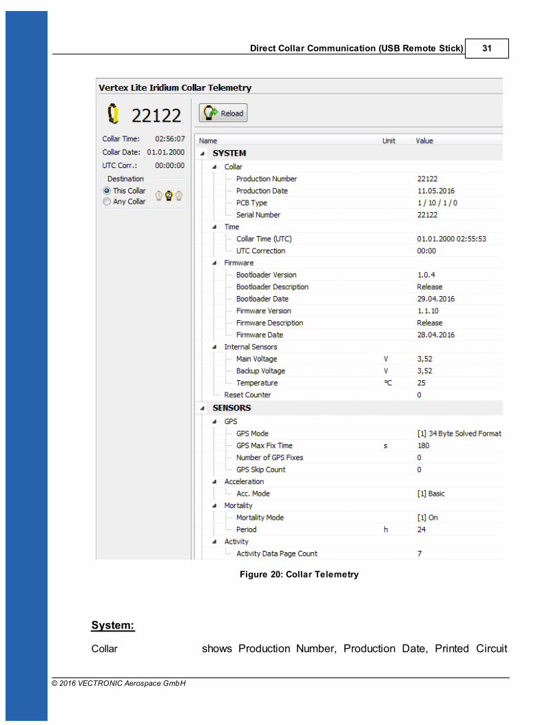
The Telemetry window gives an overview about all hardware and software settings of thecollar. It shows the actual programming with no option to change it here. That is done (asfar as the options can be altered) in the node Configuration
Direct Collar Communication (USB Remote Stick) 31
© 2016 VECTRONIC Aerospace GmbH
Figure 20: Collar Telemetry
System:
Collar shows Production Number, Production Date, Printed Circuit

VERTEX Lite Collar32
© 2016 VECTRONIC Aerospace GmbH
Board (PCB) Type and Collar ID.
Time shows the collar time in UTC and the UTC correction set for thecollar
Firmware shows information about the collar software: Bootloader andFirmware information. Internal or service related information only
Internal Sensors shows the Main Voltage and the ambient temperature of theincluded mortality sensor. The voltage is an important value toestimate collar status as described in Position
Sensors:
GPS shows information about the GPS Mode (internal usage only),GPS Max Fix Time in seconds, GPS Fix Count (number of fixescollected so far) and the GPS skip Count. The latter meaning toput only selected fixes into the transmission data (e.g. everysecond fix) and leave the rest for USB wireless data downloadonly.
Acceleration shows acceleration mode (basic)
Mortality shows the Period of the mortality sensor: the Default Periodwhich was set by VECTRONIC Aerospace and the User Periodwhich is user definable
Activity Activity Data Page Counter: counter to save activity data value(in pages)
Communication:
Radio shows information about the Transmit Frequency, ReceiveFrequency and Transmit Power of the collar
Globalstar shows the Globalstar Mode, the amount of Globalstar attemptsand the ESN number
Iridium shows the Fixes per Message (user-definable) and IMEI numberof the collar (potentially needed in collar registration)
GSM mode, destination number, and the reception delay whichdefines the delay until the GSM modem starts to send data
Beacon:
Beacon Frequency shows the frequency of the VHF beacon: the Default Frequencywhich was set by VECTRONIC Aerospace and the User defined

Direct Collar Communication (USB Remote Stick) 33
© 2016 VECTRONIC Aerospace GmbH
Frequency. Furthermore, the values of the Beacon MinFrequency and the Beacon Max Frequency are shown whichdefine in what range you are able to alter the VHF frequency
Beacon Power shows the VHF Beacon output Power.
Patterns shows information about the Standard Pattern as well as theMortality Pattern and the Low Battery Pattern of the VHFbeacon. The patterns include the Default Pattern which was setby VECTRONIC Aerospace and the User Pattern if it isconfigured. For the Low Battery Pattern you can define 'StartTime', 'Cycle Period' and 'On Duration'.
Sensor Communication:
Repetition Interval defines how often the collar transmits its UHF ID
Proximity Transmitter shows if its on / off, transmit frequency, and transmit power
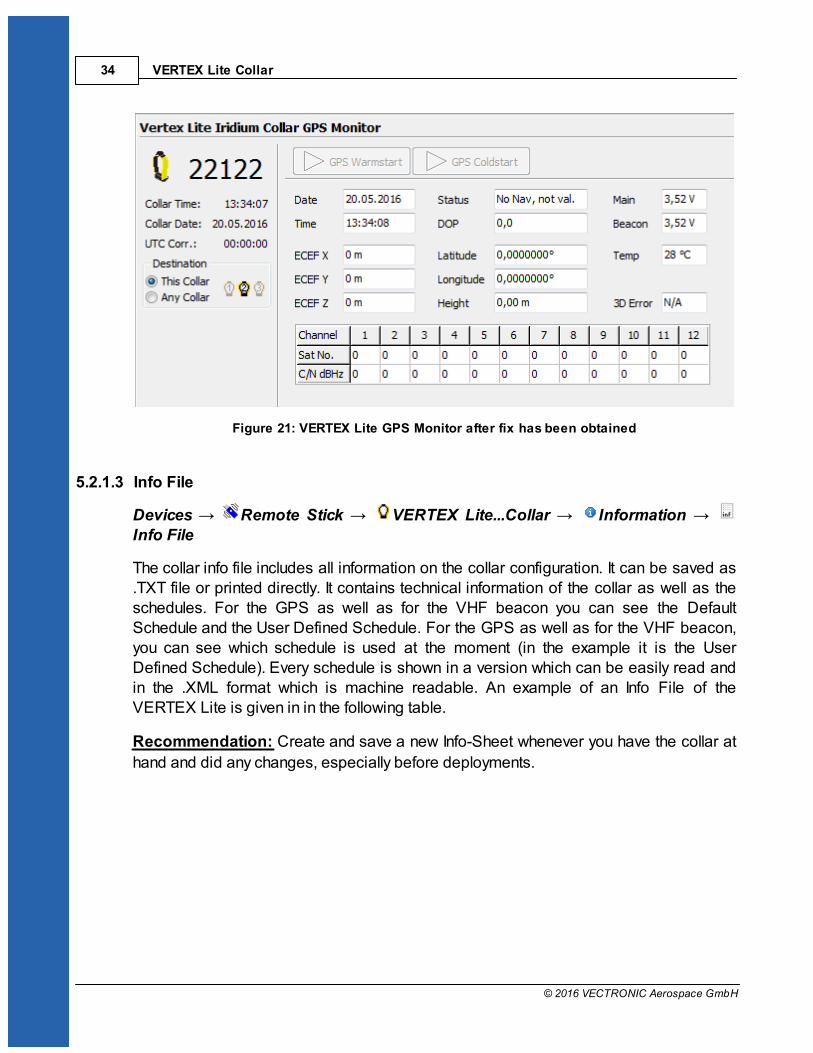
5.2.1.2 GPS Monitor
Devices Remote Stick VERTEX Lite...Collar Information GPS Monitor
The GPS monitor function allows to check the GPS receiver. There are two options inthis frame, GPS Warmstart and a GPS Coldstart. Both commands should only be usedfor diagnostics and outside of buildings with open view to the sky.
GPS Warmstart: This button will initiate a Warmstart of the collar. The GPS receiverwill use the Ephemerides and other data already stored in the collar (flash memory,remains there for roughly 2hours) and only complete them with actual satellite data. Depending on what is already stored, it can be fast or take some time. You can abortthe Warmstart by changing the node.
GPS Coldstart: The command is quite similar to the GPS Warmstart command. TheGPS receiver will skip its potentially stored ephemerides and download every availabledata from the GPS satellites anew. It will take much longer to acquire a GPS location.A GPS Coldstart is necessary if you changed the battery pack of your collar or if thecollar was inactive for a few weeks / months.
VERTEX Lite Collar34
© 2016 VECTRONIC Aerospace GmbH
Figure 21: VERTEX Lite GPS Monitor after fix has been obtained
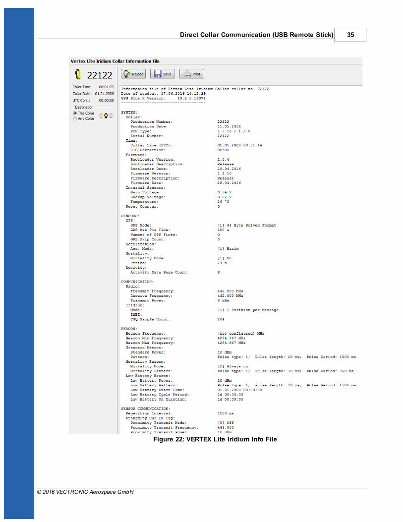
5.2.1.3 Info File
Devices Remote Stick VERTEX Lite...Collar Information Info File
The collar info file includes all information on the collar configuration. It can be saved as.TXT file or printed directly. It contains technical information of the collar as well as theschedules. For the GPS as well as for the VHF beacon you can see the DefaultSchedule and the User Defined Schedule. For the GPS as well as for the VHF beacon,you can see which schedule is used at the moment (in the example it is the UserDefined Schedule). Every schedule is shown in a version which can be easily read andin the .XML format which is machine readable. An example of an Info File of theVERTEX Lite is given in in the following table.
Recommendation: Create and save a new Info-Sheet whenever you have the collar at
hand and did any changes, especially before deployments.
Direct Collar Communication (USB Remote Stick) 35
© 2016 VECTRONIC Aerospace GmbH
Figure 22: VERTEX Lite Iridium Info File
VERTEX Lite Collar36
© 2016 VECTRONIC Aerospace GmbH
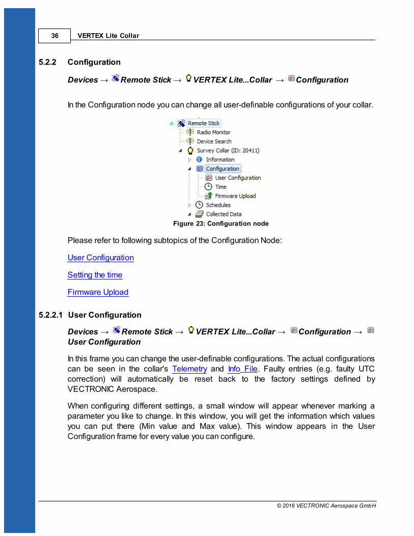
5.2.2 Configuration
Devices Remote Stick VERTEX Lite...Collar Configuration
In the Configuration node you can change all user-definable configurations of your collar.
Figure 23: Configuration node
Please refer to following subtopics of the Configuration Node:
User Configuration
Setting the time
Firmware Upload
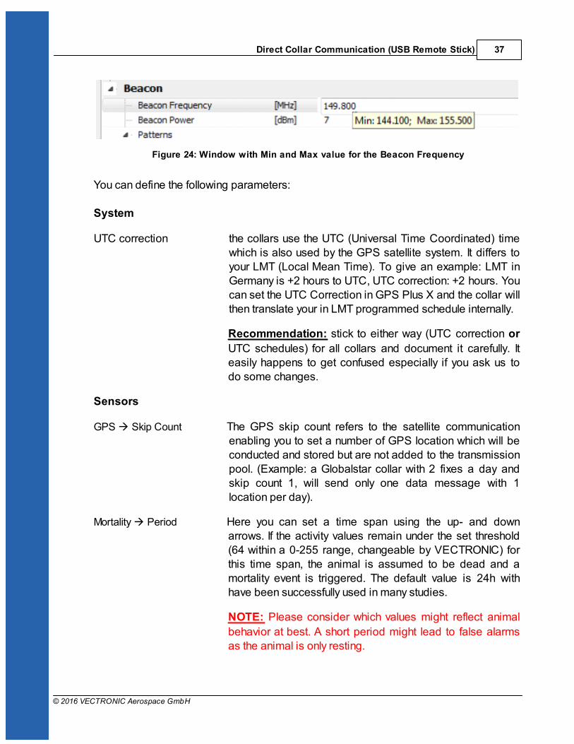
5.2.2.1 User Configuration
Devices Remote Stick VERTEX Lite...Collar Configuration User Configuration
In this frame you can change the user-definable configurations. The actual configurationscan be seen in the collar's Telemetry and Info File. Faulty entries (e.g. faulty UTCcorrection) will automatically be reset back to the factory settings defined byVECTRONIC Aerospace.
When configuring different settings, a small window will appear whenever marking aparameter you like to change. In this window, you will get the information which valuesyou can put there (Min value and Max value). This window appears in the UserConfiguration frame for every value you can configure.
Direct Collar Communication (USB Remote Stick) 37
© 2016 VECTRONIC Aerospace GmbH
Figure 24: Window with Min and Max value for the Beacon Frequency
You can define the following parameters:
System
UTC correction the collars use the UTC (Universal Time Coordinated) timewhich is also used by the GPS satellite system. It differs toyour LMT (Local Mean Time). To give an example: LMT inGermany is +2 hours to UTC, UTC correction: +2 hours. Youcan set the UTC Correction in GPS Plus X and the collar willthen translate your in LMT programmed schedule internally.
Recommendation: stick to either way (UTC correction or
UTC schedules) for all collars and document it carefully. Iteasily happens to get confused especially if you ask us todo some changes.
Sensors
GPS Skip Count The GPS skip count refers to the satellite communicationenabling you to set a number of GPS location which will beconducted and stored but are not added to the transmissionpool. (Example: a Globalstar collar with 2 fixes a day andskip count 1, will send only one data message with 1location per day).
Mortality Period Here you can set a time span using the up- and downarrows. If the activity values remain under the set threshold(64 within a 0-255 range, changeable by VECTRONIC) forthis time span, the animal is assumed to be dead and amortality event is triggered. The default value is 24h withhave been successfully used in many studies.
NOTE: Please consider which values might reflect animal
behavior at best. A short period might lead to false alarmsas the animal is only resting.

VERTEX Lite Collar38
© 2016 VECTRONIC Aerospace GmbH
Communication
Iridium The Iridium Mode (1-18) defines the number of fixes perIridium message. Please check Iridium Communication forinformation about message set-up and size.
Recommendation: Mode 4
Globalstar Choose one out of 3 modes: [0] Disabled, [1] 1 Position perMessage, [2] 2 Positions per Message
GSM The GSM Mode defines number of fixes per SMS.
Recommendation: 8 fixes per message with VAS SIM
chips
7 fixes per message with SIM cardsfrom your own provider
You can change the destination address of all incomingmessages. By default it will be the number of VECTRONICground station. If you are using your own ground station yourown mobile number is setup here.
You can configure the Reception Delay which depends onthe providers delay. The GSM module in the collar willbooked in the network for additional time to receivemessages.
Beacon
Beacon Frequency Choose the frequency of your VHF beacon by simply typingit into the field. You can only select frequency valuesbetween the minimum and maximum value.
NOTE: Signal strength is best with the primarily set value
(hardware dependent), signal strength will slightly decreaseat the rim.
Beacon Power Recommendation: Stick to the default value of 10dBm as
it offers the optimum balance between signal strength andenergy consumption. Please contact our customer service ifyou have questions.
Direct Collar Communication (USB Remote Stick) 39
© 2016 VECTRONIC Aerospace GmbH
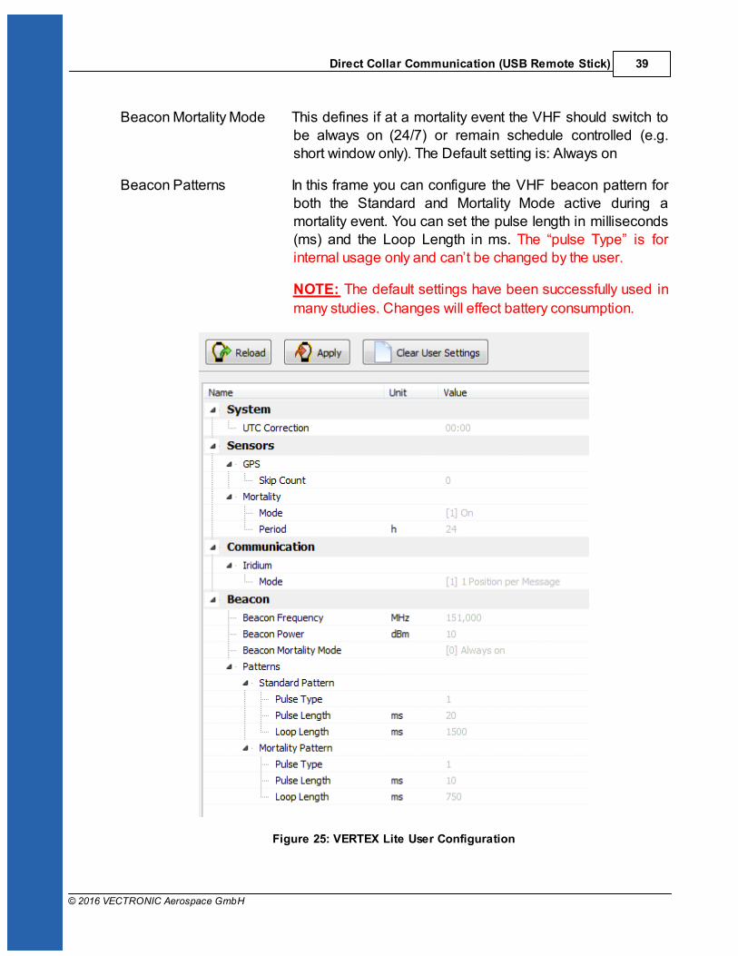
Beacon Mortality Mode This defines if at a mortality event the VHF should switch tobe always on (24/7) or remain schedule controlled (e.g.short window only). The Default setting is: Always on
Beacon Patterns In this frame you can configure the VHF beacon pattern forboth the Standard and Mortality Mode active during amortality event. You can set the pulse length in milliseconds(ms) and the Loop Length in ms. The “pulse Type” is forinternal usage only and can’t be changed by the user.
NOTE: The default settings have been successfully used in
many studies. Changes will effect battery consumption.
Figure 25: VERTEX Lite User Configuration
VERTEX Lite Collar40
© 2016 VECTRONIC Aerospace GmbH
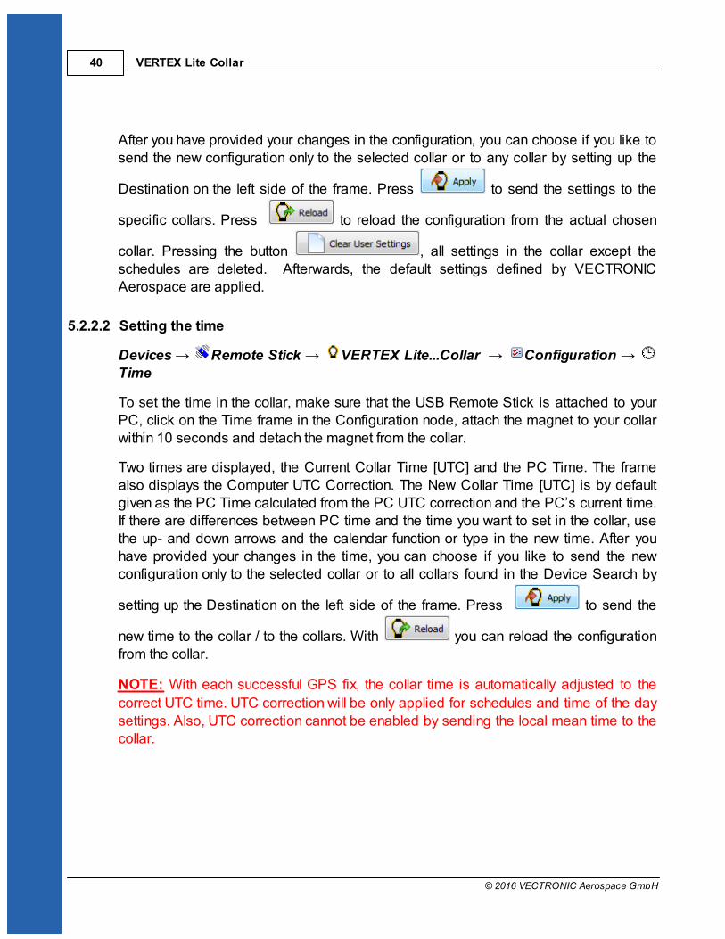
After you have provided your changes in the configuration, you can choose if you like tosend the new configuration only to the selected collar or to any collar by setting up the
Destination on the left side of the frame. Press to send the settings to the
specific collars. Press to reload the configuration from the actual chosen
collar. Pressing the button , all settings in the collar except theschedules are deleted. Afterwards, the default settings defined by VECTRONICAerospace are applied.
5.2.2.2 Setting the time
Devices Remote Stick VERTEX Lite...Collar Configuration Time
To set the time in the collar, make sure that the USB Remote Stick is attached to yourPC, click on the Time frame in the Configuration node, attach the magnet to your collarwithin 10 seconds and detach the magnet from the collar.
Two times are displayed, the Current Collar Time [UTC] and the PC Time. The framealso displays the Computer UTC Correction. The New Collar Time [UTC] is by defaultgiven as the PC Time calculated from the PC UTC correction and the PC’s current time.If there are differences between PC time and the time you want to set in the collar, usethe up- and down arrows and the calendar function or type in the new time. After youhave provided your changes in the time, you can choose if you like to send the newconfiguration only to the selected collar or to all collars found in the Device Search by
setting up the Destination on the left side of the frame. Press to send the
new time to the collar / to the collars. With you can reload the configurationfrom the collar.
NOTE: With each successful GPS fix, the collar time is automatically adjusted to the
correct UTC time. UTC correction will be only applied for schedules and time of the daysettings. Also, UTC correction cannot be enabled by sending the local mean time to thecollar.

Direct Collar Communication (USB Remote Stick) 41
© 2016 VECTRONIC Aerospace GmbH
Figure 26: Set Time Frame
5.2.2.3 Firmware Upload
Devices Remote Stick VERTEX Lite...Collar Configuration Firmware Upload
A Firmware update is only necessary if you experience problems with the current collarfirmware or need a feature only available in a newer version than the present one. In thiscase, get the appropriate file from VECTRONIC Aerospace. Select the update (.bin) file
with . Afterwards, you can see that some information appears in the window. Youcan check information on Device Model, File Type, Version (the firmware version youare going to upload to the collar) and the Version Attributes. Send the upgrade to the
collar with . The upload will be verified automatically while it is progressing.
Figure 27: Collar Firmware Upload frame

VERTEX Lite Collar42
© 2016 VECTRONIC Aerospace GmbH
5.2.3 Schedules
Devices Remote Stick VERTEX Lite...Collar Schedules
Schedules, either VHF or GPS, define when the respective sensor is on, meaning theVHF Beacon is broadcasting and the GPS receiver is conducting GPS fixes. Bothrequire battery power and some serious thoughts should be spend on beforedeployment.
Figure 28: Schedule creation window
The schedule creation window shows all option around collar creation and is more orless identical for the GPS as well as the VHF schedule builder. They differ in the ruleformat which are described in the following chapters.
Load schedule from collar (either GPS and VHF schedule)
Upload created schedule to collars ( )
Erases the collar schedule
Clears the tool window to start schedule builder anew
Loads a previously saved schedule
Saves a created schedule for later usage and control
Prints out the listed rules

Direct Collar Communication (USB Remote Stick) 43
© 2016 VECTRONIC Aerospace GmbH
Schedule builder tool: add a new rule
Schedule builder tool: delete selected rule
NOTE: Please keep in mind that the VERTEX Lite Globalstar collars can’t be
reconfigured remotely once deployed.
5.2.3.1 GPS schedule
Devices Remote Stick VERTEX Lite...Collar Schedules GPS
A GPS schedule consists of one or more rules specifying the date and time when thecollar will do GPS fixes. Each schedule consist of a varying set of rules each consistingof:
Start Date: the date when the rule should start
End Date: the date when the rule should end
Period Length: the length of the period in which the Sequence for GPSrecording is repeated.
Sequence: The sequence is a time span within the period length betweenyou like to take GPS positions. Here you can define: Offset – itdefines the time span between the start of the period and therecording of the first GPS position; Duration – period in whichthe GPS positions will be recorded with the Fix Rate repetition;Fix Rate – GPS position recording repetition rate.
NOTE: You can only take GPS fixes within the time span of the
period. This way, the sum of offset and duration must besmaller than the value of the defined period length. If you like totake only 1 GPS fix per sequence, the fix rate can equal theduration value. If you have already two position recordings inone sequence, you can delete the other sequence in the ruleeditor.
You can use up to 292 rules within one schedule and get as complex as you want (rulesfor all biological- and physical seasons, planned field operation, different study ormonitoring questions etc.).
NOTE: Iridium: Field studies have shown that the transmittal of 8 fixes per day in Mode4

VERTEX Lite Collar44
© 2016 VECTRONIC Aerospace GmbH
– 4 fixes per message) has the best energy consumption / transmittal probability ratio.Transmittal of more fixes per day will work as well but might result in a higher degree ofunsuccessful transmission attempts. Data will be reach you at some point but that mighttake some time.
Recommendation: For safety reasons you should define at least one schedule starting
on 01.01.2000. If the collar's time is reset for any reason, the timer will start at this dateand will attempt to take one fix per week until another schedule starts or until the clock isset to the correct UTC time by a successful GPS fix.
After changing the default rules to the user defined rules, you can choose if you like tosend the new schedule only to the selected collar or to all collars found in the DeviceSearch by setting up the Destination on the left side of the frame.
If you want to create a new schedule the first time (only the default schedule exists in thecollar), a notification window will appear when selecting the GPS schedule frame.
Figure 29: Notification window whenever a schedule node is activated for the first time
VERTEX Lite Iridium / GSM: You can send new schedules remotely.
NOTE: The collar will take one GPS fix per week when all schedule rules are in the
future. It will take a GPS fix every four hours when all schedules are outdated.
Direct Collar Communication (USB Remote Stick) 45
© 2016 VECTRONIC Aerospace GmbH
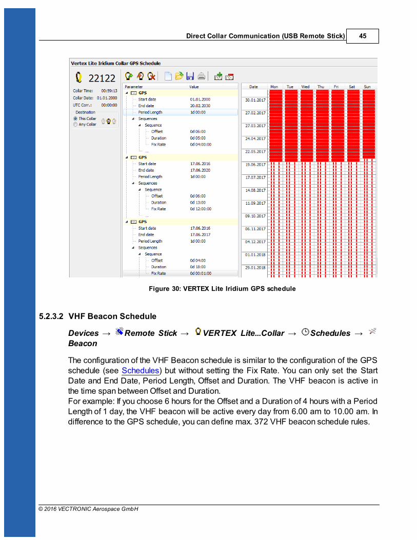
Figure 30: VERTEX Lite Iridium GPS schedule
5.2.3.2 VHF Beacon Schedule
Devices Remote Stick VERTEX Lite...Collar Schedules Beacon
The configuration of the VHF Beacon schedule is similar to the configuration of the GPSschedule (see Schedules) but without setting the Fix Rate. You can only set the StartDate and End Date, Period Length, Offset and Duration. The VHF beacon is active inthe time span between Offset and Duration. For example: If you choose 6 hours for the Offset and a Duration of 4 hours with a PeriodLength of 1 day, the VHF beacon will be active every day from 6.00 am to 10.00 am. Indifference to the GPS schedule, you can define max. 372 VHF beacon schedule rules.
VERTEX Lite Collar46
© 2016 VECTRONIC Aerospace GmbH
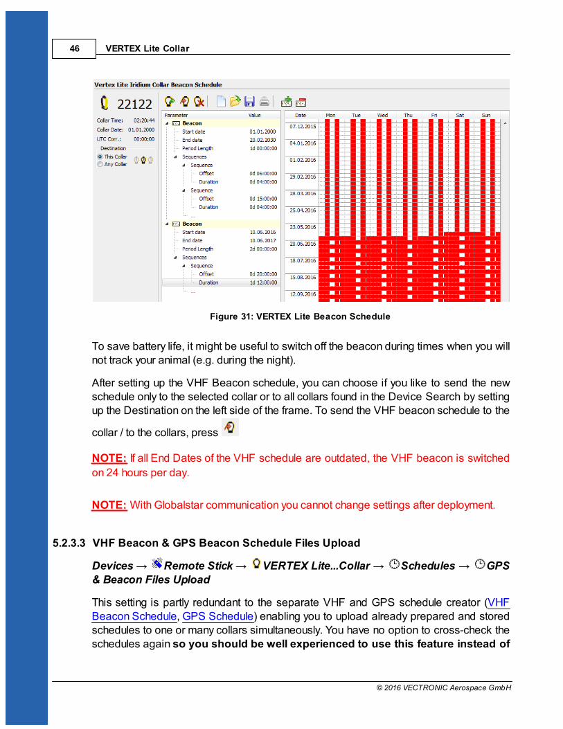
Figure 31: VERTEX Lite Beacon Schedule
To save battery life, it might be useful to switch off the beacon during times when you willnot track your animal (e.g. during the night).
After setting up the VHF Beacon schedule, you can choose if you like to send the newschedule only to the selected collar or to all collars found in the Device Search by settingup the Destination on the left side of the frame. To send the VHF beacon schedule to the
collar / to the collars, press
NOTE: If all End Dates of the VHF schedule are outdated, the VHF beacon is switched
on 24 hours per day.
NOTE: With Globalstar communication you cannot change settings after deployment.
5.2.3.3 VHF Beacon & GPS Beacon Schedule Files Upload
Devices Remote Stick VERTEX Lite...Collar Schedules GPS& Beacon Files Upload
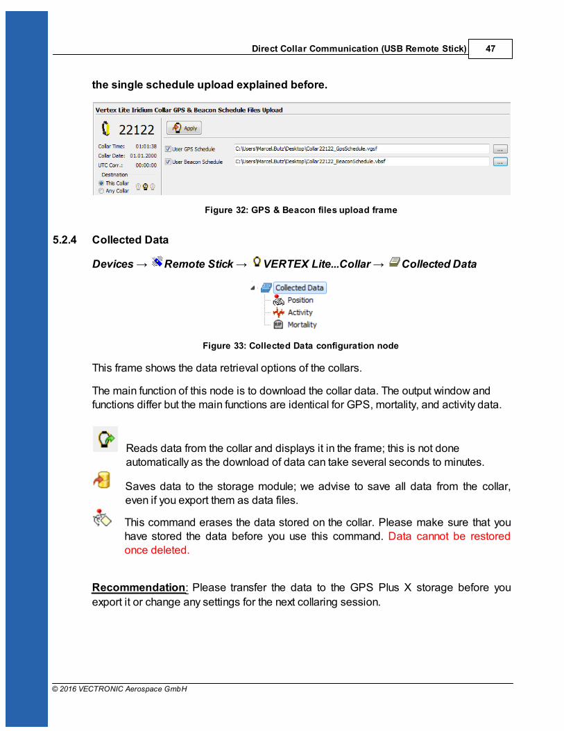
This setting is partly redundant to the separate VHF and GPS schedule creator (VHFBeacon Schedule, GPS Schedule) enabling you to upload already prepared and storedschedules to one or many collars simultaneously. You have no option to cross-check theschedules again so you should be well experienced to use this feature instead of
Direct Collar Communication (USB Remote Stick) 47
© 2016 VECTRONIC Aerospace GmbH
the single schedule upload explained before.
Figure 32: GPS & Beacon files upload frame
5.2.4 Collected Data
Devices Remote Stick VERTEX Lite...Collar Collected Data
Figure 33: Collected Data configuration node
This frame shows the data retrieval options of the collars.
The main function of this node is to download the collar data. The output window andfunctions differ but the main functions are identical for GPS, mortality, and activity data.
Reads data from the collar and displays it in the frame; this is not doneautomatically as the download of data can take several seconds to minutes.
Saves data to the storage module; we advise to save all data from the collar,even if you export them as data files.
This command erases the data stored on the collar. Please make sure that youhave stored the data before you use this command. Data cannot be restoredonce deleted.
Recommendation: Please transfer the data to the GPS Plus X storage before you
export it or change any settings for the next collaring session.
VERTEX Lite Collar48
© 2016 VECTRONIC Aerospace GmbH
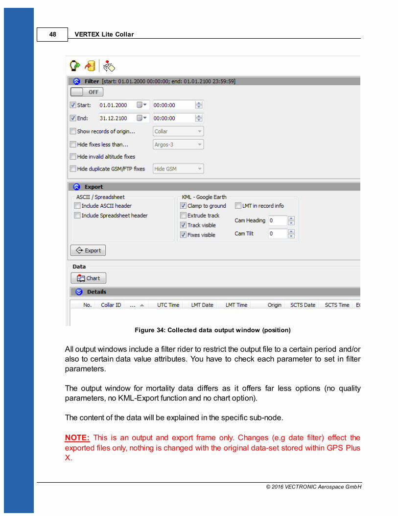
Figure 34: Collected data output window (position)
All output windows include a filter rider to restrict the output file to a certain period and/oralso to certain data value attributes. You have to check each parameter to set in filterparameters.
The output window for mortality data differs as it offers far less options (no qualityparameters, no KML-Export function and no chart option).
The content of the data will be explained in the specific sub-node.
NOTE: This is an output and export frame only. Changes (e.g date filter) effect the
exported files only, nothing is changed with the original data-set stored within GPS PlusX.
Direct Collar Communication (USB Remote Stick) 49
© 2016 VECTRONIC Aerospace GmbH
5.2.4.1 Position
Devices Remote Stick VERTEX Lite...Collar Collected Data Position
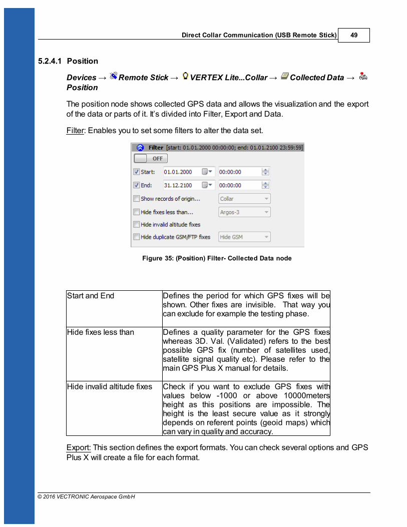
The position node shows collected GPS data and allows the visualization and the exportof the data or parts of it. It’s divided into Filter, Export and Data.
Filter: Enables you to set some filters to alter the data set.
Figure 35: (Position) Filter- Collected Data node
Start and End Defines the period for which GPS fixes will beshown. Other fixes are invisible. That way youcan exclude for example the testing phase.
Hide fixes less than Defines a quality parameter for the GPS fixeswhereas 3D. Val. (Validated) refers to the bestpossible GPS fix (number of satellites used,satellite signal quality etc). Please refer to themain GPS Plus X manual for details.
Hide invalid altitude fixes Check if you want to exclude GPS fixes withvalues below -1000 or above 10000metersheight as this positions are impossible. Theheight is the least secure value as it stronglydepends on referent points (geoid maps) whichcan vary in quality and accuracy.
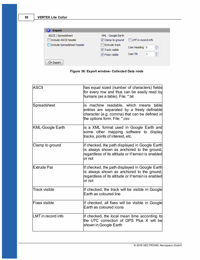
Export: This section defines the export formats. You can check several options and GPSPlus X will create a file for each format.
VERTEX Lite Collar50
© 2016 VECTRONIC Aerospace GmbH
Figure 36: Export window- Collected Data node
ASCII has equal sized (number of characters) fieldsfor every row and thus can be easily read byhumans (as a table). File: *.txt
Spreadsheet is machine readable, which means tableentries are separated by a freely definablecharacter (e.g. comma) that can be defined inthe options form. File: *.csv
KML-Google Earth is a XML format used in Google Earth andsome other mapping software to displaytracks, points of interest, etc.
Clamp to ground if checked, the path displayed in Google Earthis always shown as anchored to the ground,regardless of its altitude or if terrain is enabledor not
Extrude Pat if checked, the path displayed in Google Earthis always shown as anchored to the ground,regardless of its altitude or if terrain is enabledor not
Track visible if checked, the track will be visible in GoogleEarth as coloured line
Fixes visible if checked, all fixes will be visible in GoogleEarth as coloured icons
LMT in record info if checked, the local mean time according tothe UTC correction of GPS Plus X will beshown in Google Earth

Direct Collar Communication (USB Remote Stick) 51
© 2016 VECTRONIC Aerospace GmbH
Cam Heading viewing direction of 0 – North, 90 – West, 180– South, 270 - East
Cam Tilt inclination of the camera, 0 – straightdownwards, 90 – horizontal into viewing,direction, 180 – straight upwards, 270 -horizontal into opposite viewing direction
Data: This window shows all GPS positions with their unique values (DOP, Satellitesused etc – see below). A click on a single fix (line) will show its values in the upper partfor better visualization.
Figure 37: Data window- Collected Data node
No. line index, dependent on time stamp; this indexnumber is created when data are read out of thecollar and will not be changed when data arefiltered (this way, “data gaps” caused by filteringare easily detectable)
Collar ID ID of the collar from which the positions havebeen downloaded
UTC date and time time in Universal Time Coordinated (UTC,equivalent to GMT, without daylight saving time/summer time)
LMT date and time local mean time, depending on the value set inUTC Correction (see System UTC Correction)
VERTEX Lite Collar52
© 2016 VECTRONIC Aerospace GmbH
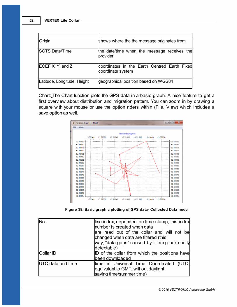
Origin shows where the the message originates from
SCTS Date/Time the date/time when the message receives theprovider
ECEF X, Y, and Z coordinates in the Earth Centred Earth Fixedcoordinate system
Latitude, Longitude, Height geographical position based on WGS84
Chart: The Chart function plots the GPS data in a basic graph. A nice feature to get afirst overview about distribution and migration pattern. You can zoom in by drawing asquare with your mouse or use the option riders within (File, View) which includes asave option as well.
Figure 38: Basic graphic plotting of GPS data- Collected Data node
No. line index, dependent on time stamp; this indexnumber is created when dataare read out of the collar and will not bechanged when data are filtered (thisway, “data gaps” caused by filtering are easilydetectable)
Collar ID ID of the collar from which the positions havebeen downloaded
UTC data and time time in Universal Time Coordinated (UTC,equivalent to GMT, without daylightsaving time/summer time)

Direct Collar Communication (USB Remote Stick) 53
© 2016 VECTRONIC Aerospace GmbH
LMT date and time local mean time, depending on the value set inUTC Correction
Origin shows where the message originates fromSCTS Date/Time the date/time when the collar has been read outECEF X, Y and Z coordinates in the Earth Centred Earth Fixed
coordinate systemLatitude, Longitude andHeight
geographical position based on WGS84
DOP (Dilution of Precision) value for the geometricconstellation of the received GPS satellites
Fix Type quality of fix obtained3D Error shows the difference [m] between the real
position and the transmittedposition
Sats used number of satellites used for the fix. Sat No/ C/NO [dBHz] channels of the GPS receiver with two columns
each containing the receivedsatellite number and the carrier to noise ratio indBHz
Main [V] voltage of the main battery in VoltsMortality Status shows if the animal was deemed alive or deadBeacon [V] voltage of the beacon battery in VoltsTemp [°C] Ambient temperature
5.2.4.2 Activity
Devices Remote Stick VERTEX Lite...Collar Collected Data ActivityFilter: Enables you to set some filters to alter the dataset.
Figure 39: Activity Data Filter

VERTEX Lite Collar54
© 2016 VECTRONIC Aerospace GmbH
Export: This section defines the export formats. There are only two formats available forthe activity data export.
Figure 40: Activity data export
ASCII has equal sized (number of characters) fields forevery row and thus can be easily read by humans(as a table). File: *.txt
Spreadsheet is machine readable, which means table entriesare separated by a freely definable character (e.g.comma) that can be defined in the options form.File: *.csv
Data: This window shows all activity data stored in the collar.
Figure 41: Activity Data Frame
Press to see a visualization of the data.
5.2.4.3 Mortality
Devices Remote Stick VERTEX Lite...Collar Collected Data

Direct Collar Communication (USB Remote Stick) 55
© 2016 VECTRONIC Aerospace GmbH
Mortality
Filter: Enables you to set some filters to alter the dataset.
Figure 42: Mortality Data Filter
Export: This section defines the export formats. There are only two formats available forthe mortality data export.
Figure 43: Mortality Data Export
ASCII has equal sized (number of characters) fields forevery row and thus can be easily read by humans(as a table). File: *.txt
Spreadsheet is machine readable, which means table entriesare separated by a freely definable character (e.g.comma) that can be defined in the options form.File: *.csv
Data: This window shows all mortality Events stored in the collar. positions with theirunique values (DOP, Satellites used etc – see below). A click on a single fix (line) willshow its values in the upper part for better visualization.
VERTEX Lite Collar56
© 2016 VECTRONIC Aerospace GmbH
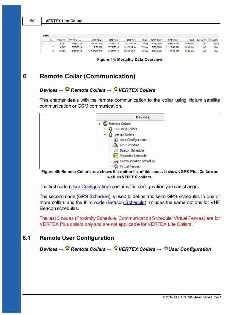
Figure 44: Mortality Data Overview
6 Remote Collar (Communication)
Devices Remote Collars VERTEX Collars
This chapter deals with the remote communication to the collar using Iridium satellitecommunication or GSM communication.
Figure 45: Remote Collars tree shows the option list of this node. It shows GPS Plus Collars as
well as VERTEX collars.
The first node (User Configuration) contains the configuration you can change.
The second node (GPS Schedule) is used to define and send GPS schedules to one ormore collars and the third node (Beacon Schedule) includes the same options for VHFBeacon schedules.
The last 3 nodes (Proximity Schedule, Communication Schedule, Virtual Fences) are forVERTEX Plus collars only and are not applicable for VERTEX Lite Collars.
6.1 Remote User Configuration
Devices Remote Collars VERTEX Collars User Configuration

Remote Collar (Communication) 57
© 2016 VECTRONIC Aerospace GmbH
Figure 46: Remote User Configuration
VERTEX Lite Collar58
© 2016 VECTRONIC Aerospace GmbH
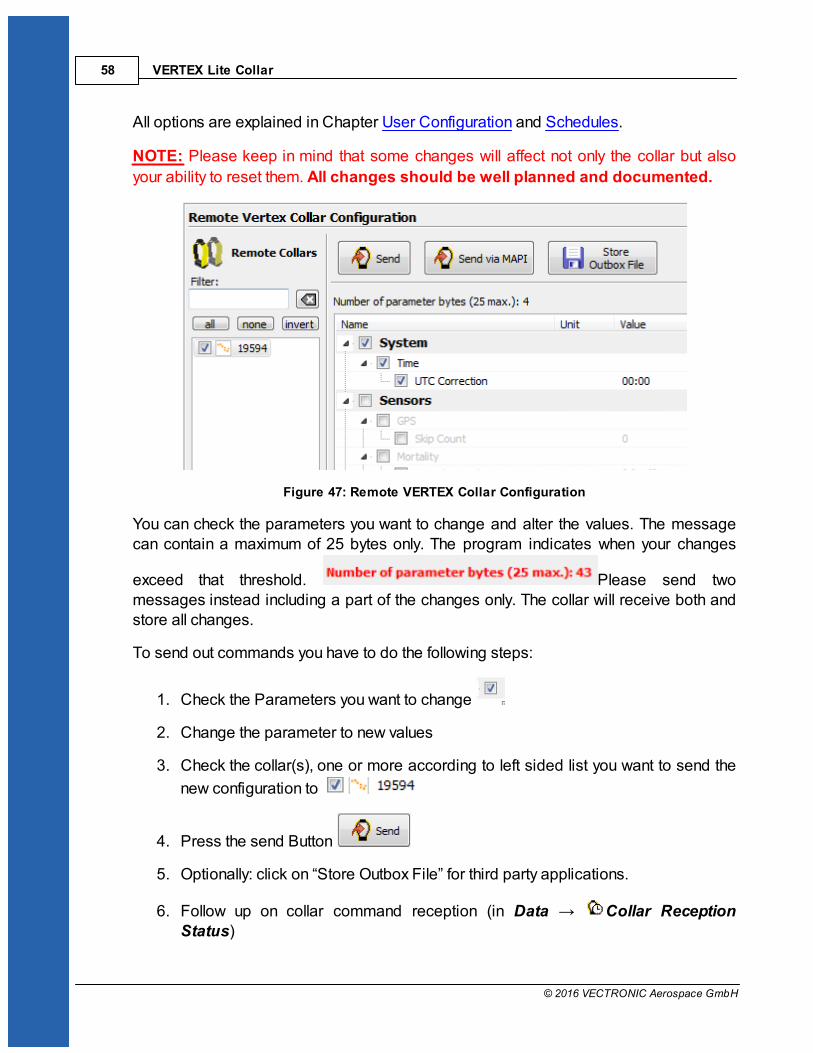
All options are explained in Chapter User Configuration and Schedules.
NOTE: Please keep in mind that some changes will affect not only the collar but also
your ability to reset them. All changes should be well planned and documented.
Figure 47: Remote VERTEX Collar Configuration
You can check the parameters you want to change and alter the values. The messagecan contain a maximum of 25 bytes only. The program indicates when your changes
exceed that threshold. Please send twomessages instead including a part of the changes only. The collar will receive both andstore all changes.
To send out commands you have to do the following steps:
1. Check the Parameters you want to change
2. Change the parameter to new values
3. Check the collar(s), one or more according to left sided list you want to send the
new configuration to
4. Press the send Button
5. Optionally: click on “Store Outbox File” for third party applications.
6. Follow up on collar command reception (in Data Collar ReceptionStatus)

Remote Collar (Communication) 59
© 2016 VECTRONIC Aerospace GmbH
NOTE: check the changes before sending them as you might have problems to change
them again (e.g. adding skip count, raising positions / messages fewer messagesfrom the collar, fewer communication windows for you).
NOTE: make sure you have chosen the correct collars only.
NOTE: Status and further information about Remote Commands can be seen in Data
Remote Command Status. Please keep track on your changes for you and yourplanning but also for us if you need support at some point.
6.2 Remote GPS Schedule
Devices Remote Collars VERTEX Collars GPS Schedule
The GPS schedule editor is identical to the one described in GPS schedule. Anyschedule send to the collar will erase the existing one on the collar, meaning you willhave to include all rules of the first one. There is a size limitation for an Iridium / GSMMessage, one message to the collar can contain 108 bytes only, respectively 4-7 rules.You might have to stick to some more basic rules, respectively plan for a certain periodand resend updates from time to time.
The software GPS Plus X will warn you whenever your schedule is invalid in rule usageor size and abort the upload. For remote communication with a GSM collar with customer SIM card, a Ground Stationis necessary. If you do not own one, please contact our customer service.
For remote communication with an Iridium collar you need to set further configurations(email address,...) to communicate with your collar. Therefore refer to the GPS Plus Xsoftware manual and search for 'Collar Command Destinations'.
The steps how you send out commands to your collar are explained in the GPS Plus Xsoftware manual, please search for 'Remote communication via GSM and IRIDIUM'.
6.3 Remote Beacon Schedule
Devices Remote Collars VERTEX Collars Beacon Schedule
The VHF Beacon schedule editor is identical to the one described in VHF Beaconschedule. Any schedule send to the collar will erase the existing one on the collar,meaning you will have to include all rules of the first one. There is a size limitation for Iridium / GSM Messages which means you won’t be able tomake new ones as complex as the first one. An Iridium / GSM message to the collar

VERTEX Lite Collar60
© 2016 VECTRONIC Aerospace GmbH
can contain 108 bytes only, respectively 5-9 VHF Beacon rules. You might have to stickto some more basic rules, respectively plan for a certain period and resend updatesfrom time to time.
The software GPS Plus X will warn you whenever your schedule is invalid in rule usageor size and abort the upload.
7 Calculate Collar Lifetime
This command estimates the lifetime of your VERTEX Lite Collar and can be found inthe Tools menu of GPS Plus X. (Tools Calculate VERTEX Collar Lifetime)
Figure 48: Tools Menu
Select your collar (e.g. VERTEX Lite Iridium and battery size) and check the settings(Position Transmission & Beacon).
NOTE: You will find recommendations to the “Position Transmission” in the specific
chapter (Iridium Communication) and we recommend to stick to the default values forthe Beacon settings (VHF Beacon).
Now you can enter a GPS and VHF Beacon schedule which are described in chapterGPS schedule and VHF Beacon schedule. After you have selected all the options for the
collar, press or to start the calculation. When pressing
or while the calculation process is running, you will cancel the
calculation. It might be useful to save the settings using the icon as this schedule
could later be used for collar configuration. The icon enables you to load schedulesinto the calculation tool, potentially retrieved from the collar as described in chapterSchedules.
Calculate Collar Lifetime 61
© 2016 VECTRONIC Aerospace GmbH
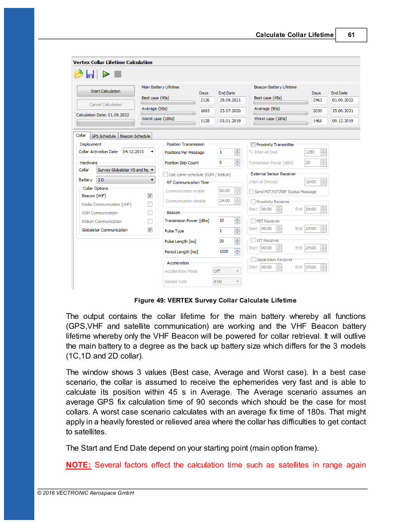
Figure 49: VERTEX Survey Collar Calculate Lifetime
The output contains the collar lifetime for the main battery whereby all functions(GPS,VHF and satellite communication) are working and the VHF Beacon batterylifetime whereby only the VHF Beacon will be powered for collar retrieval. It will outlivethe main battery to a degree as the back up battery size which differs for the 3 models(1C,1D and 2D collar).
The window shows 3 values (Best case, Average and Worst case). In a best casescenario, the collar is assumed to receive the ephemerides very fast and is able tocalculate its position within 45 s in Average. The Average scenario assumes anaverage GPS fix calculation time of 90 seconds which should be the case for mostcollars. A worst case scenario calculates with an average fix time of 180s. That mightapply in a heavily forested or relieved area where the collar has difficulties to get contactto satellites.
The Start and End Date depend on your starting point (main option frame).
NOTE: Several factors effect the calculation time such as satellites in range again
VERTEX Lite Collar62
© 2016 VECTRONIC Aerospace GmbH
affected by the habitat and potential obstacles (e.g. thick canopy) and time between twofixes and potential benefit of using existing ephemerides data (fixes within an hour).
Recommendation: please calculate with the average scenario to start with especially
when you use a Globalstar collar or work in forested habitats.
8 Test the collar
It is recommended to test the collar in advance if GPS positions are received andtransmitted as programmed before you deploy it on the animal.
1. Remove the magnet from the electronic housing (not the Drop Off magnet!)
2. Place them outdoors with clear view to the sky (NOTE: Place the collars about 1mapart otherwise their signals might interfere and effect the testing)
3. Listen for the VHF beacon signal with your tracking receiver (NOTE: check settingsfor frequency and communication windows for beacon before)
4. Wait for incoming messages (NOTE: check for expected time frames first)
5. Process incoming data and check signal quality etc.
6. Send reconfiguration commands remotely
7. Deactivate the collar by reattaching the magnet to the electronic housing
NOTE: To save battery life, leave the magnet on the collar during storage and do not
leave the collar connected to your computer if you do not use it. Disconnect the batterypack if you store the collar for months.
9 Attach the collar to the animal
The collar has no forward or backward side so you can deploy it to your liking.
Make sure the belt fits perfectly to the animal's neck. If it is too loose, the animal may
get it off. In worst case the animal might get injured by a collar too loose or tight.
Cut the overhanging belt part and smooth the cutted edge.
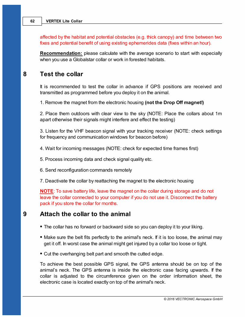
To achieve the best possible GPS signal, the GPS antenna should be on top of theanimal’s neck. The GPS antenna is inside the electronic case facing upwards. If thecollar is adjusted to the circumference given on the order information sheet, theelectronic case is located exactly on top of the animal's neck.
Attach the collar to the animal 63
© 2016 VECTRONIC Aerospace GmbH
Figure 50: Collar circumferences (a) Predefined circumference: Electronic case is exactly on
top of animal’s neck, best possible GPS reception. (b) Up to ±10% variation from predefined
circumference: Electronic case is slightly on side of animal’s neck (c) bad or no GPS reception
Make sure the magnet is removed from the electronic housing and from the Drop Off,
otherwise it stays deactivated and will not perform any GPS fixes or transfer data, andthe Drop Off will not release the collar.
If you need help or advice please contact our customer service. We will gladly bring youin touch with other scientist working on similar species.
NOTE: Please do not shorten the belt beyond the perforated beltpart as you would
possibly cut and thereby damage the VHF antenna. If you need further shortening,please get in touch with our customer service.
NOTE: Make sure the magnets are removed from the housing, otherwise the collarstays deactivated and the Drop Off will not release the collar.
10 Battery options
The VERTEX Lite Collar enables the usage of different battery sizes. All batteries canbe coupled with a Drop Off system.
The battery design itself depends on the belt shape (oval, round and oval/round) and theusage of a Drop Off system. The following table gives an overview about battery typesand weights with or without Drop Off.
Battery for round collar:

VERTEX Lite Collar64
© 2016 VECTRONIC Aerospace GmbH
without Drop Off with Drop Off
1C IG 128 g 186 g
1D IG 205 g 300 g
2D IG 329 g 430 g
3D IG 492 g 580 g
4D IG 616 g 708 g
5D IG 800 g 855 g
7D IG Ca. 1050 g
Battery for oval collar:
without Drop Off with Drop Off
1C AG 128 g 186 g
1D AG 234 g 309 g
2D AG 348 g 456 g
3D AG 512 g 603 g
4D AG 634 g 716 g
5D AG 800 g 855 g
7D AG Ca. 1050 g
curved batteries:
without Drop Off with Drop Off
3D_R 635 g 807 g
4D_R 792 g 984 g
5D_R 951 g Not available
11 Changing of battery pack
All VERTEX Lite Collars have user changeable battery packs (exception: 1c- fixbattery). Make sure to follow the instructions to prevent any damage to the collar and its

Changing of battery pack 65
© 2016 VECTRONIC Aerospace GmbH
parts when changing the battery pack.
NOTE: If you change the battery of a collar with Drop Off, please note the Drop Off
number on the battery housing. This ensures that you can reach the Drop Off that you
actually want to reach when retrieving the collar, especially for remote Drop Offs!
NOTE: Be careful when un- or replugging the battery connector pins since they can
break if bended.
NOTE: Store the battery package at room temperature.
There are 3 different belt shapes. For each shape the battery changing procedurediffers a little. Please follow the links for the respective instructions.
Oval collar
Round Collar, standard battery pack
Round collar, curved battery pack
11.1 Oval Collar
Figure 51: Battery Connector on oval collar
Unscrew the two nuts attaching the battery pack to the adjustable side of the collar withan 8 or 7 mm (depending on collar size) hexagon socket wrench (delivered with thecollar). Remove the black base plate. The screws are integrated into the battery packand cannot be removed.

VERTEX Lite Collar66
© 2016 VECTRONIC Aerospace GmbH
Figure 52: Removing the battery connector from oval collar
Unscrew the two nuts and remove the washer on the non-adjustable side of the collarwith the battery connector. Carefully pull the battery connector from the battery pack
(Figure above, left). The battery pin socket is located between the two screws (Figureabove, centre).To attach a new battery pack, replace the O-ring on the battery plug and carefully push
the three threaded pins of the connector plug into the connector socket (Figure above,right). Be careful to avoid any damage to the connector! Place the washer on thethreaded pins and reattach the collar with new self-locking nuts to ensure that the O-ringof the nuts is not damaged.
NOTE: After you changed the battery pack of your collar, a GPS coldstart is necessary.For this please refer to GPS Monitor.
11.2 Round Collar, standard battery pack
Figure 53: Battery connector on round collar, standard battery pack
Remove the screws attaching the bracket to the battery pack with an 8 or 7 mm(depending on collar size) hexagon socket wrench (delivered with the collar). Start withthe screws on the adjustable side and then remove the screws attaching the batteryconnector.
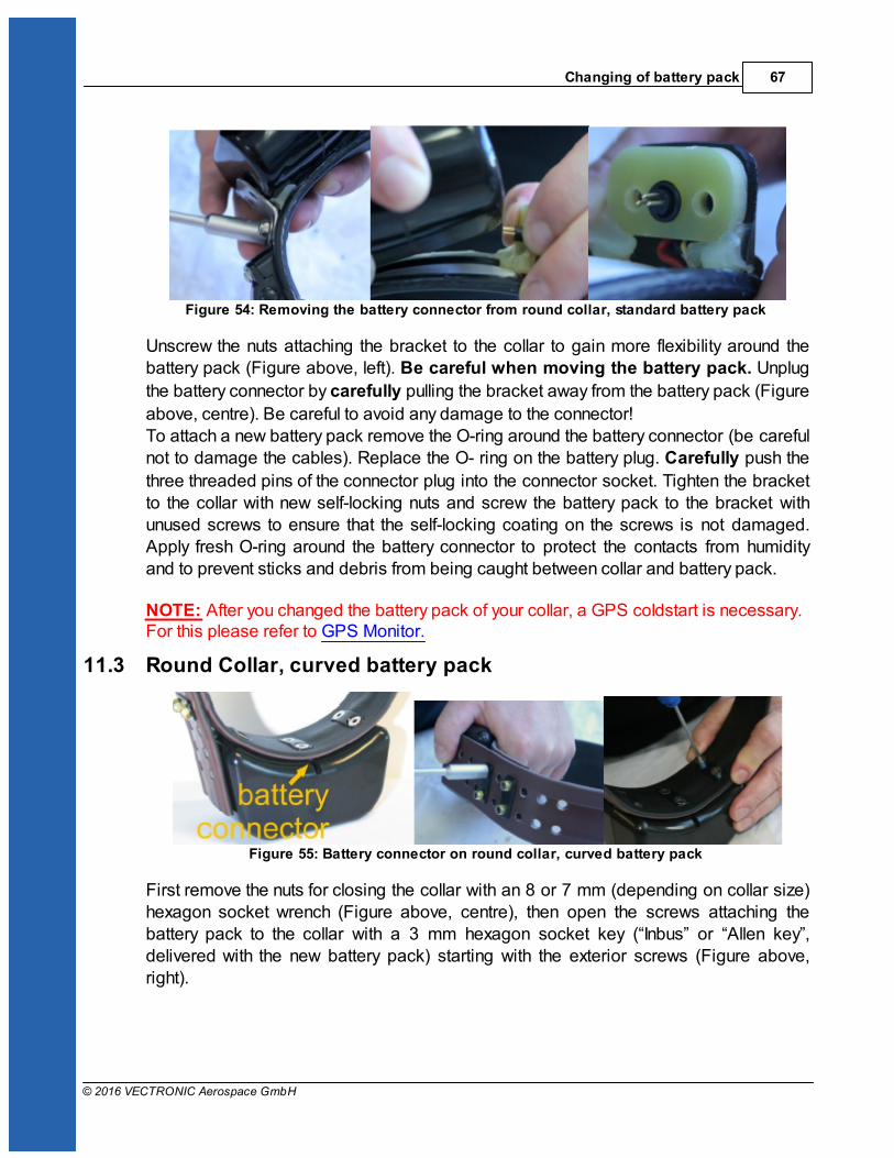
Changing of battery pack 67
© 2016 VECTRONIC Aerospace GmbH
Figure 54: Removing the battery connector from round collar, standard battery pack
Unscrew the nuts attaching the bracket to the collar to gain more flexibility around thebattery pack (Figure above, left). Be careful when moving the battery pack. Unplug
the battery connector by carefully pulling the bracket away from the battery pack (Figure
above, centre). Be careful to avoid any damage to the connector!To attach a new battery pack remove the O-ring around the battery connector (be carefulnot to damage the cables). Replace the O- ring on the battery plug. Carefully push the
three threaded pins of the connector plug into the connector socket. Tighten the bracketto the collar with new self-locking nuts and screw the battery pack to the bracket withunused screws to ensure that the self-locking coating on the screws is not damaged.Apply fresh O-ring around the battery connector to protect the contacts from humidityand to prevent sticks and debris from being caught between collar and battery pack.
NOTE: After you changed the battery pack of your collar, a GPS coldstart is necessary.For this please refer to GPS Monitor.
11.3 Round Collar, curved battery pack
Figure 55: Battery connector on round collar, curved battery pack
First remove the nuts for closing the collar with an 8 or 7 mm (depending on collar size)hexagon socket wrench (Figure above, centre), then open the screws attaching thebattery pack to the collar with a 3 mm hexagon socket key (“Inbus” or “Allen key”,delivered with the new battery pack) starting with the exterior screws (Figure above,right).

VERTEX Lite Collar68
© 2016 VECTRONIC Aerospace GmbH
Figure 56: Removing the battery connector from round collar, curved battery pack
Unplug the battery connector by pulling the collar away from the battery pack (Figureabove, left). You can support this by very carefully wedging a flat screwdriver between
the battery connector and the battery pack (Figure above, right). Be careful to avoid anydamage to the connector!
Figure 57: Battery connector and plugs on round collar, curved battery pack
Above you can see the battery socket (left) and pins (right). To attach a new batterypack, exchange the O-ring on the battery plug and carefully plug the three threaded
battery pins into the socket.
Figure 58: Attachment of curved battery pack to round collar with two metal base plates (left)and two Fastlock washers (right)
In older collars, the battery packs are fixed to the belt with six screws and three metal
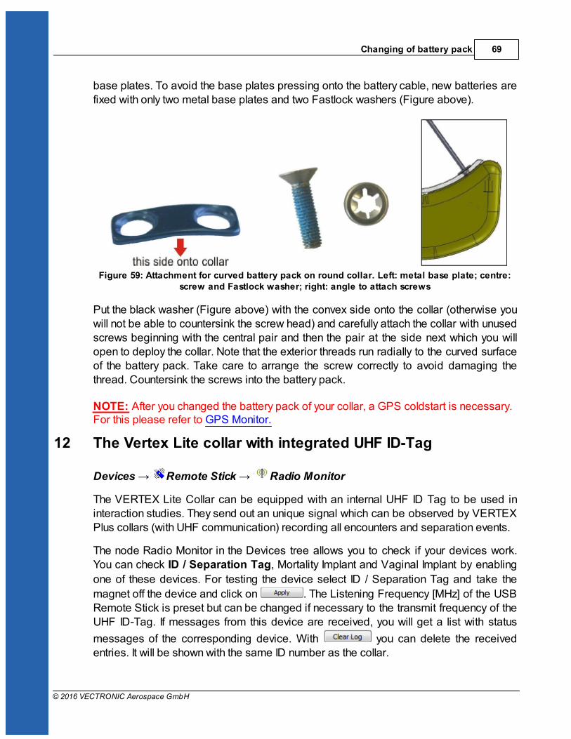
Changing of battery pack 69
© 2016 VECTRONIC Aerospace GmbH
base plates. To avoid the base plates pressing onto the battery cable, new batteries arefixed with only two metal base plates and two Fastlock washers (Figure above).
Figure 59: Attachment for curved battery pack on round collar. Left: metal base plate; centre:screw and Fastlock washer; right: angle to attach screws
Put the black washer (Figure above) with the convex side onto the collar (otherwise youwill not be able to countersink the screw head) and carefully attach the collar with unusedscrews beginning with the central pair and then the pair at the side next which you willopen to deploy the collar. Note that the exterior threads run radially to the curved surfaceof the battery pack. Take care to arrange the screw correctly to avoid damaging thethread. Countersink the screws into the battery pack.
NOTE: After you changed the battery pack of your collar, a GPS coldstart is necessary.For this please refer to GPS Monitor.
12 The Vertex Lite collar with integrated UHF ID-Tag
Devices Remote Stick Radio Monitor
The VERTEX Lite Collar can be equipped with an internal UHF ID Tag to be used ininteraction studies. They send out an unique signal which can be observed by VERTEXPlus collars (with UHF communication) recording all encounters and separation events.
The node Radio Monitor in the Devices tree allows you to check if your devices work.You can check ID / Separation Tag, Mortality Implant and Vaginal Implant by enabling
one of these devices. For testing the device select ID / Separation Tag and take the
magnet off the device and click on . The Listening Frequency [MHz] of the USBRemote Stick is preset but can be changed if necessary to the transmit frequency of theUHF ID-Tag. If messages from this device are received, you will get a list with status
messages of the corresponding device. With you can delete the receivedentries. It will be shown with the same ID number as the collar.
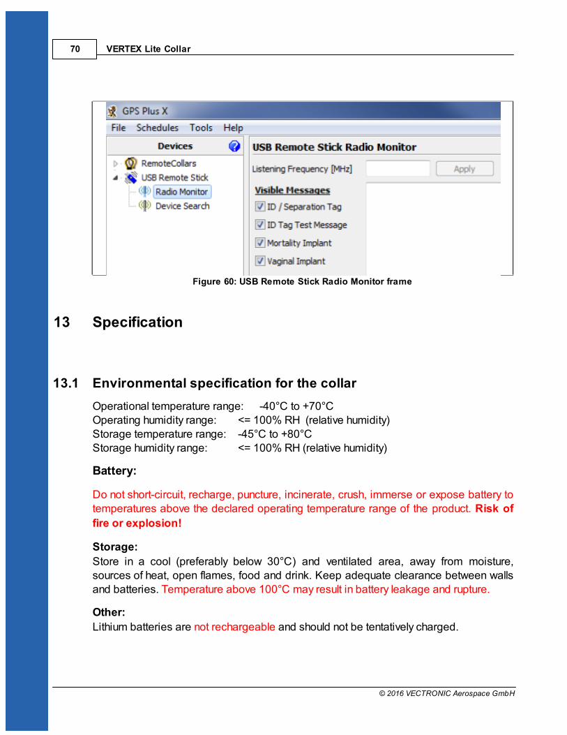
VERTEX Lite Collar70
© 2016 VECTRONIC Aerospace GmbH
Figure 60: USB Remote Stick Radio Monitor frame
13 Specification
13.1 Environmental specification for the collar
Operational temperature range: -40°C to +70°COperating humidity range: <= 100% RH (relative humidity)Storage temperature range: -45°C to +80°C Storage humidity range: <= 100% RH (relative humidity)
Battery:
Do not short-circuit, recharge, puncture, incinerate, crush, immerse or expose battery totemperatures above the declared operating temperature range of the product. Risk of
fire or explosion!
Storage:
Store in a cool (preferably below 30°C) and ventilated area, away from moisture,sources of heat, open flames, food and drink. Keep adequate clearance between wallsand batteries. Temperature above 100°C may result in battery leakage and rupture.
Other:
Lithium batteries are not rechargeable and should not be tentatively charged.

Specification 71
© 2016 VECTRONIC Aerospace GmbH
Disposal Considerations:
Do not incinerate, or subject cells to temperatures in excess of 100°C. Such abuse
can result in loss of seal, leakage, and/or cell explosion.
Do not dispose of the battery with the regular garbage, but in accordance with
appropriate local regulations.
13.2 Declarations of Conformity
Declaration of Conformity for USA
This device complies with Part 15 of the FCC Rules. Operation is subject to thefollowing two conditions:
(1)this device may not cause harmful interference, and
(2)this device must accept any interference received, including interference that maycause undesired operation.
Usually this is followed by the following FCC caution:
Any changes or modifications not expressly approved by the party responsible forcompliance could void the user's authority to operate this equipment.
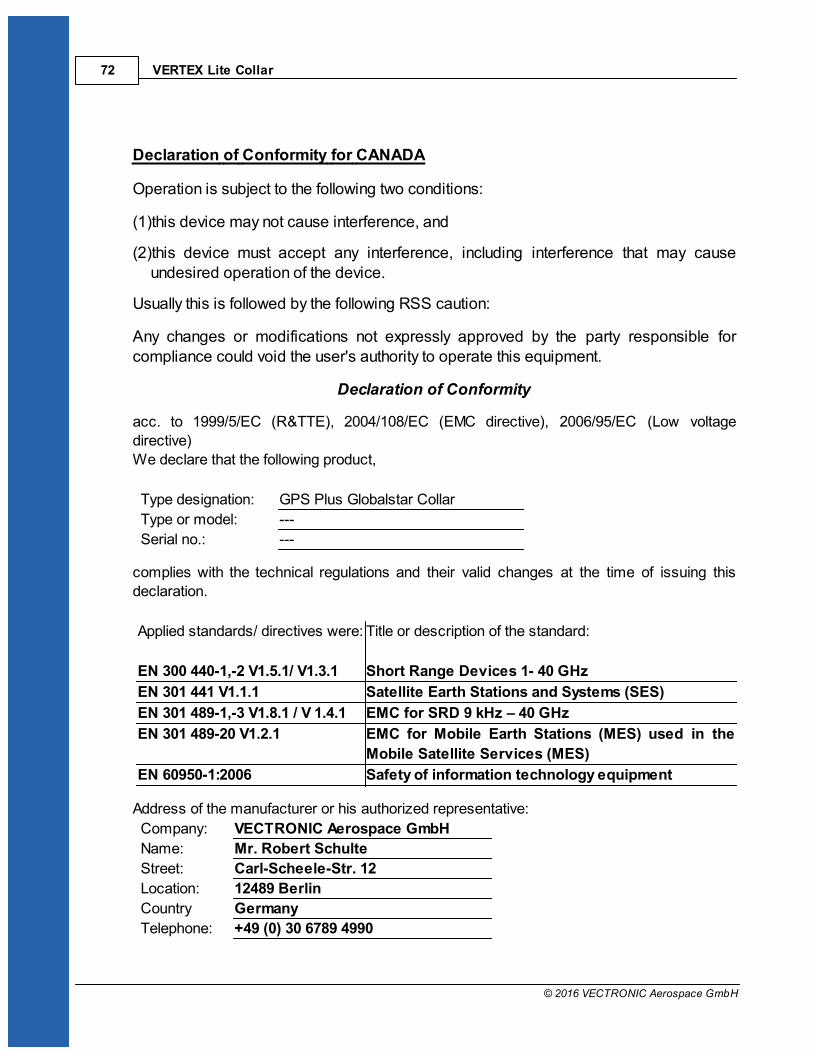
VERTEX Lite Collar72
© 2016 VECTRONIC Aerospace GmbH
Declaration of Conformity for CANADA
Operation is subject to the following two conditions:
(1)this device may not cause interference, and
(2)this device must accept any interference, including interference that may causeundesired operation of the device.
Usually this is followed by the following RSS caution:
Any changes or modifications not expressly approved by the party responsible forcompliance could void the user's authority to operate this equipment.
Declaration of Conformity
acc. to 1999/5/EC (R&TTE), 2004/108/EC (EMC directive), 2006/95/EC (Low voltage
directive)
We declare that the following product,
Type designation: GPS Plus Globalstar Collar
Type or model: ---
Serial no.: ---
complies with the technical regulations and their valid changes at the time of issuing this
declaration.
Applied standards/ directives were: Title or description of the standard:
EN 300 440-1,-2 V1.5.1/ V1.3.1 Short Range Devices 1- 40 GHz
EN 301 441 V1.1.1 Satellite Earth Stations and Systems (SES)
EN 301 489-1,-3 V1.8.1 / V 1.4.1 EMC for SRD 9 kHz – 40 GHz
EN 301 489-20 V1.2.1 EMC for Mobile Earth Stations (MES) used in the
Mobile Satellite Services (MES)
EN 60950-1:2006 Safety of information technology equipment
Address of the manufacturer or his authorized representative:
Company: VECTRONIC Aerospace GmbH
Name: Mr. Robert Schulte
Street: Carl-Scheele-Str. 12
Location: 12489 Berlin
Country Germany
Telephone: +49 (0) 30 6789 4990
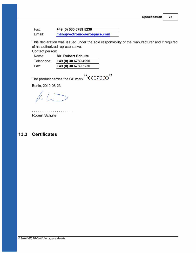
Specification 73
© 2016 VECTRONIC Aerospace GmbH
Fax: +49 (0) 030 6789 5230
Email: [email protected]
This declaration was issued under the sole responsibility of the manufacturer and if required
of his authorized representative:
Contact person:
Name: Mr. Robert Schulte
Telephone: +49 (0) 30 6789 4990
Fax: +49 (0) 30 6789 5230
The product carries the CE mark “ ”Berlin, 2010-08-23
. . . . . . . . . . . . . . . . . . . . . .
Robert Schulte
13.3 Certificates
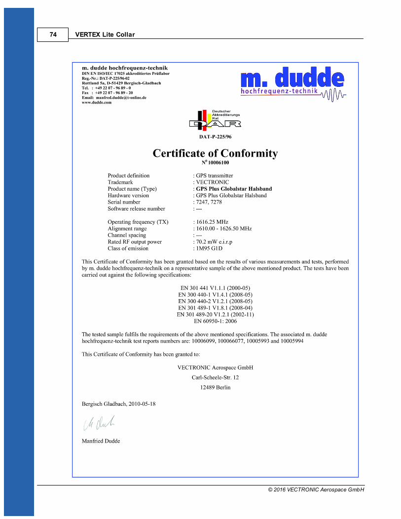
VERTEX Lite Collar74
© 2016 VECTRONIC Aerospace GmbH
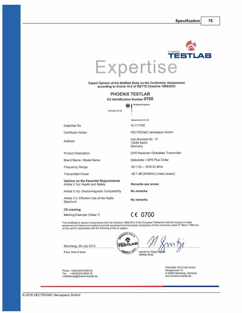
Specification 75
© 2016 VECTRONIC Aerospace GmbH
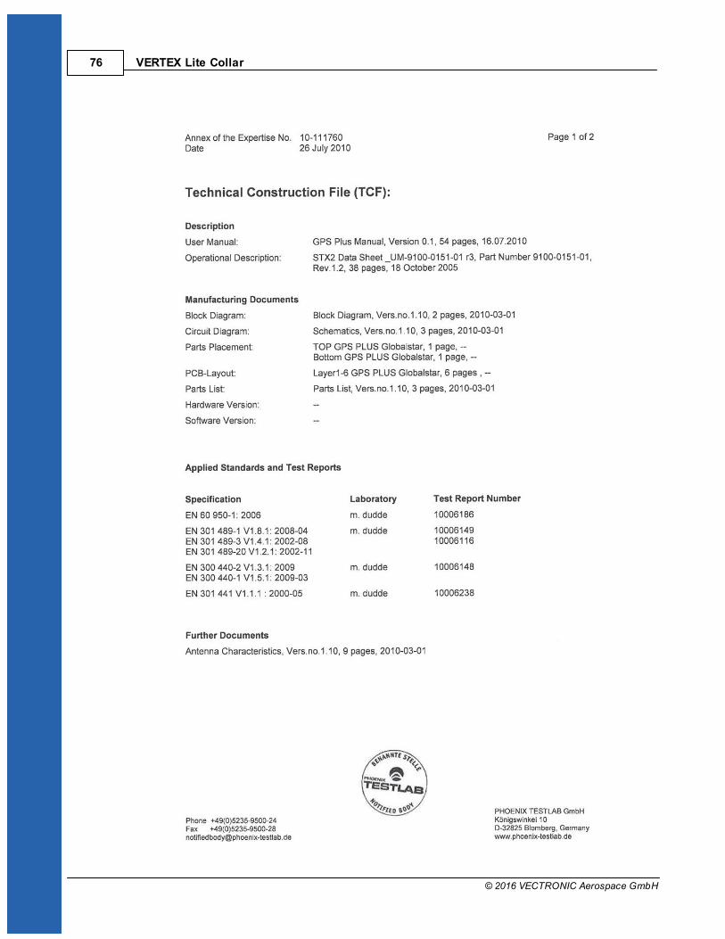
VERTEX Lite Collar76
© 2016 VECTRONIC Aerospace GmbH
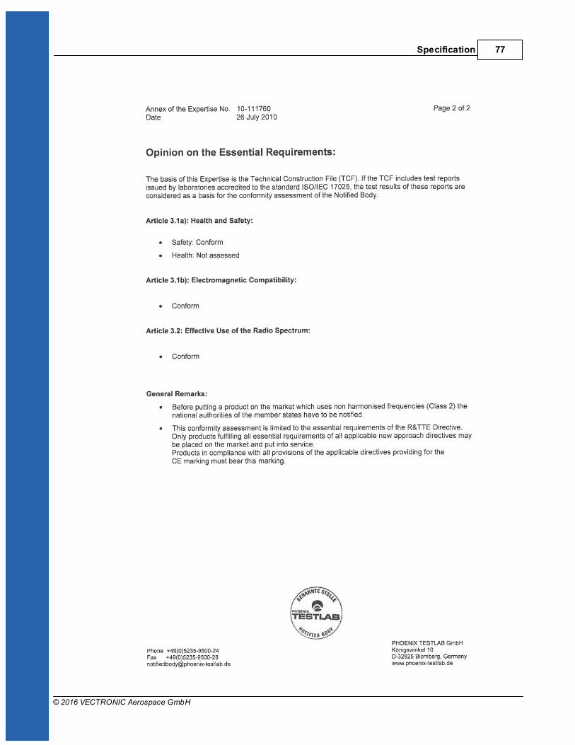
Specification 77
© 2016 VECTRONIC Aerospace GmbH

VERTEX Lite Collar78
© 2016 VECTRONIC Aerospace GmbH
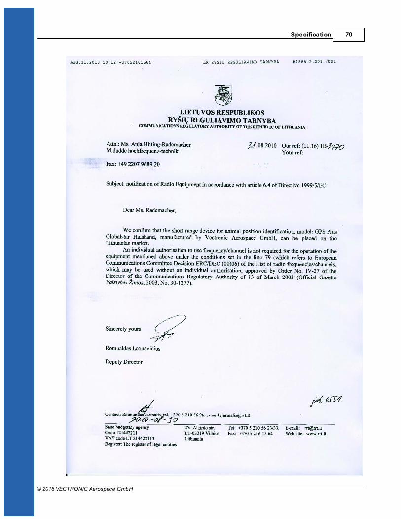
Specification 79
© 2016 VECTRONIC Aerospace GmbH

VERTEX Lite Collar80
© 2016 VECTRONIC Aerospace GmbH

Specification 81
© 2016 VECTRONIC Aerospace GmbH

VERTEX Lite Collar82
© 2016 VECTRONIC Aerospace GmbH
Specification 83
© 2016 VECTRONIC Aerospace GmbH