verify correct ez flap model selection not unsafe
TRANSCRIPT
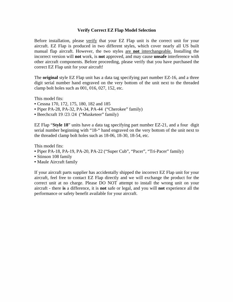
Verify Correct EZ Flap Model Selection Before installation, please verify that your EZ Flap unit is the correct unit for your aircraft. EZ Flap is produced in two different styles, which cover nearly all US built manual flap aircraft. However, the two styles are not interchangeable. Installing the incorrect version will not work, is not approved, and may cause unsafe interference with other aircraft components. Before proceeding, please verify that you have purchased the correct EZ Flap unit for your aircraft! The original style EZ Flap unit has a data tag specifying part number EZ-16, and a three digit serial number hand engraved on the very bottom of the unit next to the threaded clamp bolt holes such as 001, 016, 027, 152, etc. This model fits: • Cessna 170, 172, 175, 180, 182 and 185 • Piper PA-28, PA-32, PA-34, PA-44 (“Cherokee” family) • Beechcraft 19 /23 /24 (“Musketeer” family) EZ Flap “Style 18” units have a data tag specifying part number EZ-21, and a four digit serial number beginning with “18-“ hand engraved on the very bottom of the unit next to the threaded clamp bolt holes such as 18-06, 18-30, 18-54, etc. This model fits: • Piper PA-18, PA-19, PA-20, PA-22 (“Super Cub”, “Pacer”, “Tri-Pacer” family) • Stinson 108 family • Maule Aircraft family If your aircraft parts supplier has accidentally shipped the incorrect EZ Flap unit for your aircraft, feel free to contact EZ Flap directly and we will exchange the product for the correct unit at no charge. Please DO NOT attempt to install the wrong unit on your aircraft - there is a difference, it is not safe or legal, and you will not experience all the performance or safety benefit available for your aircraft.

STOP! FAA Documentation Requirement
The FAA requires the STC holder (EZ Flap) to keep records of the aircraft type, registration and serial number of every aircraft upgraded with this STC. The FAA approval of this product also requires that an “Installation Authority” STC approval is issued and signed by the STC holder (not the installing mechanic) for your specific aircraft, and is placed in the aircraft records.
This is in addition to your mechanic signing the logbooks and FAA Form 337
It is the legal responsibility of the aircraft owner and/or the installing mechanic to get the FAA approved “installation authority” issued for the specific aircraft and signed by the STC holder. By purchasing and/or installing this product, the aircraft owner agrees to furnish the STC holder with the aircraft type, registration and serial number of the aircraft, and to keep the “installation authority” form as part of the aircraft records. The installation of this EZ Flap STC product is not approved, and the aircraft cannot be returned to service, and no warranty or guarantee will be honored until the aircraft information is furnished to the STC holder and “installation authority” form is signed and issued for each aircraft being upgraded with this STC. To comply with these FAA requirements, you may choose either of the following: Fill out the included “Installation Authority” form with 1) the name and address of the aircraft owner, 2) aircraft type (C-172, etc.), registration (N12345, etc.), serial number (172-12345) and mail it to:
To: EZ Flap Installation Authority 21033 Strathern St. Canoga Park, CA 91304
OR: Contact EZ Flap 818-634-9762 , or you may e-mail [email protected] Subject: Installation Authority
Thank you for your purchase of the EZ Flap flap handle extension STC !

EZ Flap FAA-PMA STC# SA02246LA
Cessna Piper Maule Stinson Beech www.ezflaphandle.com
For Installation or Operational Problems Call 818-634-9762
Installation Authority
Permission and authority is hereby given to ______________________________for the
installation of STC SA02246LA and the associated FAA-PMA flap handle
extension/assist device on the following individual aircraft:
_______________________________________________________________________ .
Type of Aircraft Registration Serial Number
The installation shall be accomplished in accordance with EZ Flap installation instruction
manual ___________ and also in accordance with AC 43.13-1B. The mechanic(s)
performing, inspecting and certifying the installation of this STC is responsible for
insuring that this STC does not interfere with any part of the aircraft or installed aircraft
equipment, and that the installation does not have any adverse effect on any previously
approved configuration, and that the EZ Flap device does not interfere with the normal
operation of any flight or engine controls.
By installing this STC, the installing mechanic(s) certify that the device has been
installed properly, fully function-tested and shown to be safe for flight operations, that
the aircraft owner(s)/pilot(s) have been informed of the proper operation of this STC, and
that all documentation including Instructions for Continued Airworthiness are placed in
the aircraft records.
_____________________________________
EZ Flap Date William M. Berle

You will need: • Drill with #36 or 7/64” bit • 6-32 “plug tap” (or shortened standard tap) • Phillips and flat screwdrivers • 3/16” Allen hex key wrench • Drop cloth, rags, towel, etc. to cover flap mechanism • Medium strength thread locking compound, “Loctite” or equivalent • Ruler or measuring tape • Grease pencil, chalk, or temporary marker • Good quality grease
Before you begin installation of EZ Flap First, determine whether your aircraft is equipped with an aluminum flap un-lock button (thumb button) or whether you have a plastic un-lock button. • If your aircraft has the aluminum button, delete step 1A. • If your Cessna aircraft has a plastic button, proceed
with step 1A before Step 2. (See Appendix 1) • Beech aircraft with flat-topped plastic buttons, delete
step 1A, if button is domed proceed with step 1A. Move the flap handle to the fully deployed position and al-low the un-lock button to engage, locking the flaps in this position.
EZ Flap Flap Handle Extension STC SA 02246LA Installation Procedure C-100 and P-300
(applicability: Cessna 170-185, Piper PA-20/22/28/32/34/44, Beech 19/23/24)
Drawing #9 Installation & Adjustment Instructions
Release Date September 10, 2010
Revision D William M. Berle
REV Description Date Signature
NC Initial Release 6-24-09 W. Berle
A Rewritten per AEG Comments
7-15-09 W. Berle
B Added further in-struction to flatten plastic buttons
11-24-09 W. Berle
C Address Common-ality with Piper Aircraft Version of EZ Flap and factory pre-assembly
3-25-10 W. Berle
D Add Piper and Beech Models
9-10-10 W. Berle
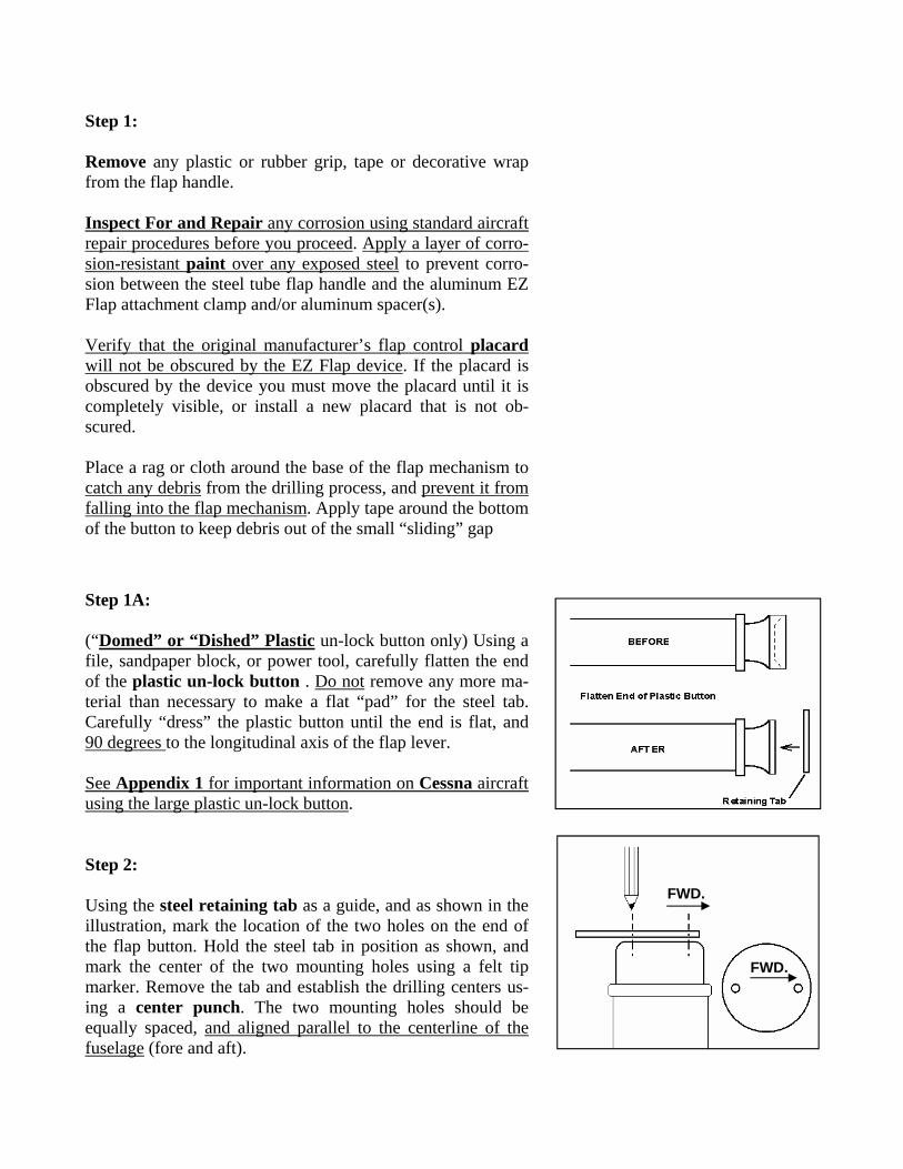
Step 1: Remove any plastic or rubber grip, tape or decorative wrap from the flap handle. Inspect For and Repair any corrosion using standard aircraft repair procedures before you proceed. Apply a layer of corro-sion-resistant paint over any exposed steel to prevent corro-sion between the steel tube flap handle and the aluminum EZ Flap attachment clamp and/or aluminum spacer(s). Verify that the original manufacturer’s flap control placard will not be obscured by the EZ Flap device. If the placard is obscured by the device you must move the placard until it is completely visible, or install a new placard that is not ob-scured. Place a rag or cloth around the base of the flap mechanism to catch any debris from the drilling process, and prevent it from falling into the flap mechanism. Apply tape around the bottom of the button to keep debris out of the small “sliding” gap Step 1A: (“Domed” or “Dished” Plastic un-lock button only) Using a file, sandpaper block, or power tool, carefully flatten the end of the plastic un-lock button . Do not remove any more ma-terial than necessary to make a flat “pad” for the steel tab. Carefully “dress” the plastic button until the end is flat, and 90 degrees to the longitudinal axis of the flap lever. See Appendix 1 for important information on Cessna aircraft using the large plastic un-lock button. Step 2: Using the steel retaining tab as a guide, and as shown in the illustration, mark the location of the two holes on the end of the flap button. Hold the steel tab in position as shown, and mark the center of the two mounting holes using a felt tip marker. Remove the tab and establish the drilling centers us-ing a center punch. The two mounting holes should be equally spaced, and aligned parallel to the centerline of the fuselage (fore and aft).
FWD.
FWD.

Step 3: When satisfied that the holes are marked correctly, drill the holes with a #36 or 7/64” drill to a depth of 3/4”. Using a “starting tap” (if possible), followed by a “plug tap”, tap the holes for 6-32 thread size, backing out the tap frequently to prevent breaking it, and cleaning the cutting debris from the tap. Test-fit the 6-32 screws and re-tap if needed until they engage into the hole fully. When satisfied, clean all debris out the tapped holes and screws using solvent spray. Carefully remove the tape, and remove all debris from the air-craft flap handle tube area. A “shop-vac” with small attach-ments is recommended. Verify that the button can be de-pressed normally with only a small thumb force. Important! If your aircraft’s flap system requires significant thumb “push” force to un-lock the flap mechanism, stop now and clean, lubricate or repair the flap system until it oper-ates smoothly and with only a slight force. Step 4: Spacers: • On Cessna 170 and 170A (early aircraft with 3/4” diameter
flap handle) install two thick aluminum spacers p/n EZ-24 between the Cessna flap handle and the EZ Flap, with the “slots” at the 3 and 9 O' Clock position.
• On Piper aircraft (most with 7/8” diameter flap handle) - install the thin wall tubular spacer p/n EZ-23 onto the Piper flap handle before installing EZ Flap, with the “slot” at the 3 O’Clock position.
• (If your EZ Flap unit did not include the correct spacer, contact EZ Flap and it will be supplied free of charge.)
Place the EZ Flap handle, with the appropriate spacer(s) if applicable, onto the aircraft flap handle, making sure that the outer cable sheath is in the small notch at the forward edge of the lower clamp before the spacer is sandwiched between the EZ Flap and the aircraft flap handle. The sheath is NOT pinched between the spacer and the aircraft flap handle! Install the lower clamp shell and bolts, but do not tighten the bolts yet.
Sheath
Slots at 3 and 9 O’ Clock Position
Early C-170 with 3/4” diameter flap handle

(Step 4, continued) Cessna installations: Make an ink or chalk mark on the upper rearward surface of the Cessna flap handle, 3 1/8 inches be-hind the end of the Cessna flap handle, as shown in the illustra-tion. Move the front face of the clamp rearward to the chalk mark 3 1/8” behind the end of the tube. Beech installations: Lower the flap lever to the zero (retracted) position. Position the lower EZ Flap main clamp next to, but not touching, the Beech fuel selector valve at the valve han-dle’s closest position (right tank selected) with flaps at zero. Make sure the EZ Flap main clamp does not contact the plas-tic trim “ring” surrounding the fuel valve, and does not restrict access to the fuel valve, and that it remains clear of the valve in all positions. Piper installations: Move the clamp (and appropriate spacer) rearward until the rear face contacts the rivet or screw in the tube a few inches behind the end. The sheath gets “captured” between the spacer and in the notch in the main clamp, it does not go into the “slot” of the tubular spacer. Push the flap button down with your thumb and swing the flap handle through its full movement (zero flap through full flap) several times while adjusting the position of the EZ Flap unit forward or aft if needed. Find the best position for EZ Flap, where it stays clear of the instrument panel, all flight and en-gine controls, fuel valves and controls, seats and seat cushions, etc. throughout the entire range of movement. Once the correct position is found, move the cable sheath in and out through the lower clamp notch until the front edge of the sheath is just behind the end of the flap handle tube (not the button). Verify that the cable sheath lays down straight on top of the flap handle. When the cable sheath is in the notch, and the front edge of the sheath is just behind the end of the aircraft flap handle tube, and the lower clamp/spacer is positioned correctly (see nota-tions above), tighten the clamp bolts just lightly snug.
Cessna Installation
Piper Installation

Step 5: Gently rotate the EZ Flap unit until the upper EZ Flap handle is on the centerline of the aircraft, between the seats. On Cessnas, the EZ Flap is angled a few degrees. Now move the flap control through its full range of movement once again and verify that it stays clear of the instrument panel, all flight and engine controls, fuel valves and controls, seats and seat cushions, etc. Finally, apply thread-lock to the clamp bolt threads (recommended), re-install and tighten the clamp bolts snug. Do not over-tighten or apply enough force to bend the flap handle tube. EZ Flap must be able to be kicked out of the way (rotated down) for emergency exit with moderate effort. Step 6: At this stage, the steel tab is still hanging from the cable above the lock button. Install the tubular foam comfort grip . Slide it over the (loose) steel tab and lock button, onto the flap handle, capturing the exposed cable sheath. (Applying a light film of grease inside the grip will make it much easier ) Beech installations: Trim the length of foam grip first so it does not cover any of the cable, button or steel tab or interfere with movement.
Piper installations: The lower foam grip is optional. Trim the length of the tubular foam first so it does not cover any of the cable, button or steel tab or interfere with movement.
On later Cessna aircraft with the larger plastic button, in-stalling the foam grip may be difficult. If you have difficulty installing the grip, you may wish to use an alternate grip or attachment method, see Appendix 1 for more information. Step 7: Place the steel retaining tab back onto the flap lock button with the (captured) cable end on the center line of the air-craft’s flap lever. Install the steel tab onto the button using the screws. Use a drop of a medium strength thread locking com-pound such as “Loctite” on the screws to reduce maintenance and prevent the screws from loosening over time.
Push on This Way

Step 8: Adjustment Loosen the trigger bolt so the cable can slide freely through the slug. Apply a drop of medium strength thread-locking compound to the bolt threads and reinstall the bolt. With the trigger bolt not tightened against the cable, verify that the flap control is in the fully deployed position and the un-lock button is fully extended (locked). Wiggle the flap handle up and down if necessary to insure the button is fully in the locked position. Slide the cable rearward until the swaged “stop sleeve” is resting against the steel retaining tab. Holding the stop sleeve against the steel tab, move the slug (by holding the trigger bolt) so that the trigger bolt is 1/16” behind (or above) the bottom of the slot in the upright tube. Tighten the bolt until it securely clamps the cable between the trigger bolt and the set screw inside the slug. Lower the flaps to the fully retracted (cruise) position and al-low the button to snap forward (locked). If not done already snap the plastic decorative cap into the top upright tube, and slide the small soft plastic protective cap over the copper stop sleeve.
Step 9: Testing Verify that the “stop sleeve” can be pulled 1/16” away (forward) from the steel tab before the trigger bolt contacts the bottom part of the slot. Verify that pulling the trigger bolt upwards with your finger results in the cable pulling the aircraft’s un-lock button in, unlocking the flap lever. Verify also that moving the trigger bolt fully provides a bit more button movement than the minimum necessary to unlock the flap handle. Verify that the flaps do not un-lock until the trigger bolt is pulled approximately 50% of its movement. Verify that the flap un-lock button “snaps” firmly back into the locked position when the trigger bolt is released and the flap handle is moved into each and every flap position. Verify that there is no interference between the steel retaining tab or the cable stop sleeve and the in-strument panel, engine controls, any sub-panel, switch panel, any avionics or electrical components, etc.
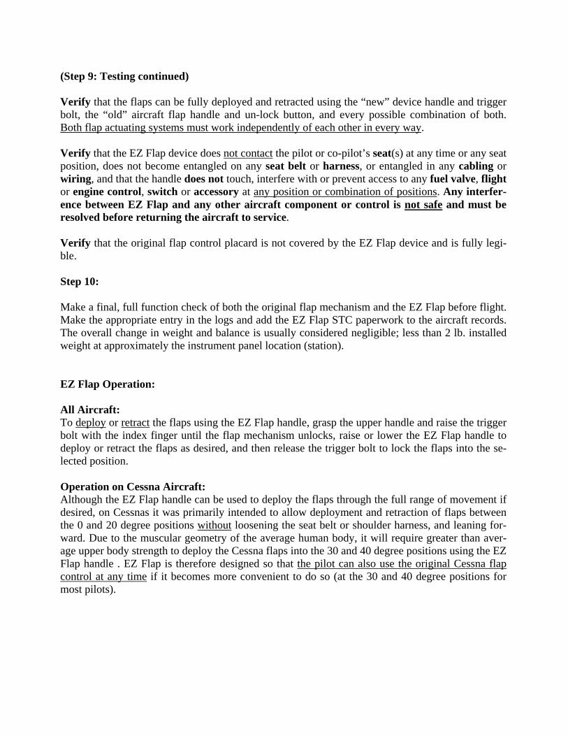
(Step 9: Testing continued) Verify that the flaps can be fully deployed and retracted using the “new” device handle and trigger bolt, the “old” aircraft flap handle and un-lock button, and every possible combination of both. Both flap actuating systems must work independently of each other in every way. Verify that the EZ Flap device does not contact the pilot or co-pilot’s seat(s) at any time or any seat position, does not become entangled on any seat belt or harness, or entangled in any cabling or wiring, and that the handle does not touch, interfere with or prevent access to any fuel valve, flight or engine control, switch or accessory at any position or combination of positions. Any interfer-ence between EZ Flap and any other aircraft component or control is not safe and must be resolved before returning the aircraft to service. Verify that the original flap control placard is not covered by the EZ Flap device and is fully legi-ble. Step 10: Make a final, full function check of both the original flap mechanism and the EZ Flap before flight. Make the appropriate entry in the logs and add the EZ Flap STC paperwork to the aircraft records. The overall change in weight and balance is usually considered negligible; less than 2 lb. installed weight at approximately the instrument panel location (station). EZ Flap Operation: All Aircraft: To deploy or retract the flaps using the EZ Flap handle, grasp the upper handle and raise the trigger bolt with the index finger until the flap mechanism unlocks, raise or lower the EZ Flap handle to deploy or retract the flaps as desired, and then release the trigger bolt to lock the flaps into the se-lected position. Operation on Cessna Aircraft: Although the EZ Flap handle can be used to deploy the flaps through the full range of movement if desired, on Cessnas it was primarily intended to allow deployment and retraction of flaps between the 0 and 20 degree positions without loosening the seat belt or shoulder harness, and leaning for-ward. Due to the muscular geometry of the average human body, it will require greater than aver-age upper body strength to deploy the Cessna flaps into the 30 and 40 degree positions using the EZ Flap handle . EZ Flap is therefore designed so that the pilot can also use the original Cessna flap control at any time if it becomes more convenient to do so (at the 30 and 40 degree positions for most pilots).


EZ Flap flap handle extension device General Maintenance and Inspection
Any time that moving the EZ Flap trigger bolt does not easily move the aircraft un-lock button a little more than what is needed to un-lock the flap lever (due to cable stretch or general wear), repeat Step 8: Final Adjustment to take any slack out of the cable and re-tighten the trigger bolt. Check the proper operation of the EZ Flap handle extension device through the full range of travel during each pre-flight inspection, verifying that the un-lock button “snaps” firmly into the extended (locked) position when the flap lever reaches each position.
Suggested annual or 100 hour inspection/maintenance checklist Lightly lubricate the inside of the upright tube and aluminum slug using good quality grease at each 100 hour / annual inspection, or when any significant friction is felt in the trigger mecha-nism while actuating the flaps. Move the trigger and aluminum slug through its full travel sev-eral times to insure the grease is spread along the sides of the slug, and that there is no “grabbing” or “galling” between the tube and slug. Lubricate the exposed surface of the cable (at the front of the cable sheath) with several drops of thin penetrating oil at each 100 hour / annual inspection, or when any significant friction is felt in the trigger mechanism while actuating the flaps. Make sure the penetrating oil is dribbled into the cable sheath along the cable, while actuating the cable back and forth with the trigger, to work the oil back into the cable sheath. Inspect lower clamp bolts for looseness at each 100 hour / annual inspection, or when any looseness / movement is felt in the main attachment while actuating the flaps. Inspect the trigger bolt and steel tab attach screws for looseness at each 100 hour/annual in-spection, or when any slippage or looseness is felt while actuating the flaps.
Message From the Inventor
I sincerely hope that your EZ Flap upgrade provides you with a safer, more enjoyable flying experience, and that you enjoy increased capabilities and additional controllability of your air-craft. If you experience any problems installing or using your EZ Flap, feel free to contact me at [email protected] or the contact phone number at the website www.ezflaphandle.com . I’d also love to hear your stories of how EZ Flap improved your ability to get the most out of your aircraft, or enhanced your safety and convenience! Bill Berle Inventor/Designer, EZ Flap