ver.1.4.0 stc zao/zao controller/stc hdview user … · the smart-telecaster zao (“stc zao”) is...
TRANSCRIPT

Ver.1.4.0
STC Zao/Zao Controller/STC HDView
User Guide
Soliton Systems K.K.
Rev.1.5

- 1 -
LEGAL NOTICES
The copyright and any other rights concerning “Smart-telecaster Zao,” “STC Zao,” “Zao Controller,”
and “STC HDView” belong to Soliton Systems K.K.
Windows is a trademark of Microsoft Corporation.
VP8 is a patent-protected Google product.
Other patents, trademarks, and copyrights included herein are the property of their respective
owners.
AES library of Mr. Isao Mori is stored in this product.
Reproducing or modifying any portion of the product is prohibited.
Design and specifications subject to change without notice.
The connection condition written in this book is one example that does not provide a guarantee.
Soliton Systems K.K.
2-4-3 SHINJUKU, SHINJUKU-KU, TOKYO 160-0022 JAPAN

- 2 -
CONTENTS
1 Overview ............................................................................................................................................... 4
2 Safety Information ............................................................................................................................... 5
2.1 Handling the Power Supply and Battery Equipment ..................................................................... 5
2.2 Additional Warnings .......................................................................................................................... 5
3 Product Specifications ......................................................................................................................... 6
3.1 STC Zao Specifications ..................................................................................................................... 6
3.2 STC HDView Specifications .............................................................................................................. 7
4 Notice .................................................................................................................................................... 8
5 STC Zao Assenbly ................................................................................................................................ 9
5.1 Outline and connection method ..................................................................................................... 9
5.1.1 Front side .................................................................................................................................... 9
5.1.2 Upper Side ................................................................................................................................. 10
5.1.3 Left side, Right side ................................................................................................................. 11
5.1.4 Power Supply ............................................................................................................................ 11
5.2 Usage ................................................................................................................................................ 12
5.2.1 Startup ....................................................................................................................................... 12
5.2.2 LIVE mode ................................................................................................................................. 12
5.2.3 SETTING mode .......................................................................................................................... 14
5.2.4 POWER mode............................................................................................................................. 18
5.2.5 Power off ................................................................................................................................... 18
5.2.6 Operation Lock ......................................................................................................................... 19
5.2.7 LED ............................................................................................................................................. 20
6 Zao Controller .................................................................................................................................... 21
6.1 Usage ................................................................................................................................................ 21
6.2 Install ................................................................................................................................................ 21
6.3 How to connect ................................................................................................................................. 21
6.4 Usage ................................................................................................................................................. 21
6.4.1 Startup ....................................................................................................................................... 21
6.4.2 Main Screen ............................................................................................................................... 22
6.4.3 Network settings ...................................................................................................................... 23
6.4.4 Video and Audio setting ......................................................................................................... 26
6.4.5 Setting destination ................................................................................................................... 28
6.4.6 Preset screen ............................................................................................................................ 31
6.4.7 Setup screen ............................................................................................................................. 32
7 STC HDView ........................................................................................................................................ 36

- 3 -
7.1 Requirements for Receiver ............................................................................................................. 36
7.2 Startup .............................................................................................................................................. 38
7.2.1 Main screen ............................................................................................................................... 38
7.3 Audio Input/Output .......................................................................................................................... 42
7.4 Edit Settings ..................................................................................................................................... 43
7.5 Common settings .............................................................................................................................. 49
- 4 -
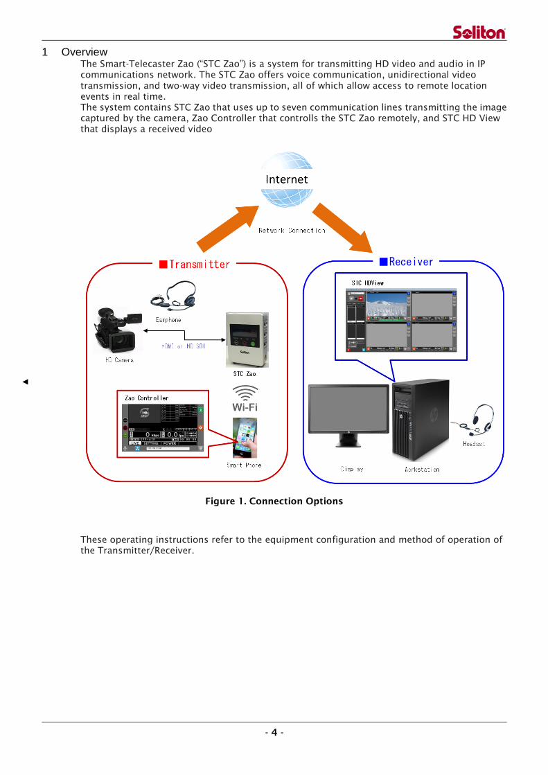
1 Overview The Smart-Telecaster Zao (“STC Zao”) is a system for transmitting HD video and audio in IP
communications network. The STC Zao offers voice communication, unidirectional video
transmission, and two-way video transmission, all of which allow access to remote location
events in real time.
The system contains STC Zao that uses up to seven communication lines transmitting the image
captured by the camera, Zao Controller that controlls the STC Zao remotely, and STC HD View
that displays a received video
Figure 1. Connection Options
These operating instructions refer to the equipment configuration and method of operation of
the Transmitter/Receiver.

- 5 -
2 Safety Information
WARNING! Be sure to read all safety precautions before operating the STC Zao or any of its
components.
2.1 Handling the Power Supply and Battery Equipment
Risk of electrical fire or shock
Keep product away from heat.
Do not handle the power adapter or battery equipment with wet hands.
Do not forcibly bend or twist the power cable.
Do not plug in the power adapter in the octopus legs wiring.
2.2 Additional Warnings
Risk of product failure
Do not leave the product in direct sunlight for an extended period of time.
Do not drop the product of place heavy products on top of it.
Do not attempt to disassemble the product.
Do not use any type of power source other than that indicated in these instructions.
Risk of serious injury
Discontinue use if product begins to smoke.
Do not use product if any parts are damaged.
Do not use product if it feels hot to the touch.
Do not use product of it emits an unusual smell.
Do not use the product if any liquids or other foreign matter are inside.

- 6 -
3 Product Specifications
3.1 STC Zao Specifications
ITEM DETAILS
Weight 900g
Dimension 123mm×160mm×46mm
Power Connector Cannon4pin × 2
LAN RJ45 × 1
Video Input HD-SDI BNC × 1
HDMI HDMI × 1
Input 1080/59.94i, 1080/50i
480/59.94i, 576/50i
USB for Modem USB2.0 × 6
Headphones output 3.5Φjack × 1
Accessories supplied AC Power× 1
V-mount battery plate × 1
USB cable with latch × 6
HDMI cable with fixing screw× 1
USB memory (housing) × 1
WiFi dongle(housing) × 1
Transition bag × 1
CD-ROM × 1
Main Function Live Relay(One-way video, Two-way audio)
Communication Line 3G、LTE、Wireless LAN、Wired LAN、Satellite
Error Correction ARQ、Packet sort
Protocol UDP/IP(RASCOW)
Encryption AES256bit
Authentication Passphrase(Up to 32characters)
Multilink Up to 7 lines
Connecting Method Manual, Startup automatic, Reconnecting
Non-Communication
limit
Max 30sec
Video
Codec H.265 Main Profile
Pixels(Video input
setting: 59.94i)
Max 720×480
Pixels(Video input
setting: 50i)
Max 720×576
Pixels(HD) Max 1920×1080
Bitrate 200kbps~10Mbps
Framerate Max 59.94 field/sec (Video input setting: 59.94i)

- 7 -
Max 59.94fps (Video input setting: 50i)
*Please see ”Setting mode (Switch a video input signal)”
on page 17.
Audio Codec Vorbis
Channel Stereo/Mono×1ch
Sampling 16bit、48KHz、22.05KHz、11.05KHz、8KHz
Input Embedded Audio
Output Analog・audio output×1
3.2 STC HDView Specifications
ITEM DETAILS
Main Function Live Relay(One-way video, Two-way audio)
Accumulation file reception*, file reception *,
Still image capture*
* : not supported by Zao
Connection Possible Product STC Zao、STC HDCam、Smart-telecaster for iOS ML
Available concurrent connections 4
Delay 240msec~30000msec
Codec Video VP8、H.265
Audio Vorbis
Operating
Environment
Hardware HP Z420 Workstation
OS Windows7 Professional
CPU Intel Xeon
Memory 8GB+
(Four of the same physical memory is required)
External
Output
Video Card Blackmagic Design Decklink Quad (4output)
Signal Format SDI or HD-SDI(By the transmitter connection)

- 8 -
4 Notice
The accompanying AC adapter is AC100V ~ 240V, 50Hz / 60Hz support, but the power cable is
domestic only.
IDX Inc. V-mount battery recommended
If you do not use the product for a long time, please remove the battery and AC adapter.
STC Zao employs an audio sampling rate of 48KHz
STC Zao features a Wi-Fi dongle with USB memory. Do not remove it.
The modem can be set only with the Zao Controller. It cannot be set from the STC Zao. Once you
have set the modem, you do not need to set it again.
Note: This equipment has been tested and found to comply with the limits for a Class A digital
device, pursuant to part 15 of the FCC Rules. These limits are designed to provide reasonable
protection against harmful interference when the equipment is operated in a commercial
environment. This equipment generates, uses, and can radiate radio frequency energy and, if
not installed and used in accordance with the instruction manual, may cause harmful
interference to radio communications. Operation of this equipment in a residential area is likely
to cause harmful interference in which case the user will be required to correct the interference
at his own expense.

- 9 -
5 STC Zao Assembly
This chapter describes STC Zao, connection procedures and the preparation.
Figure 2. Connection Option for the STC Zao
5.1 Outline and connection method
5.1.1 Front side
Front side of STC Zao consists of a display, LEDs and operation buttons.
Figure 3. Front View of STC Zao
Display
LED
Operation button

- 10 -
◆ Display
The display describes the status of the camera connection, status of the network
connection, bit rate, frame rate, status of video transmission, time of live broadcasting,
etc.
*Please refer to “5.2.2 LIVE mode” for more detail.
◆ LED
CONNECTED · · · · · · · Displays the connection status.
REC · · · · · · · · · · · · · · Displays the record status.
*Record function will be available in a future version.
BATT1 · · · · · · · · · · · · Displays the battery status of Main power supply.
BATT2 · · · · · · · · · · · · Displays the battery status of Sub power supply.
*Please refer to “5.2.7 LED” for more detail.
◆ Operation button
MODE · · · · · · · · · · · · Switch LIVE mode/SETTING mode/POWER mode.
STOP · · · · · · · · · · · · · Stop live broadcasting, power off
START · · · · · · · · · · · · Start live broadcasting, final determination
(Power off/Live broadcasting end)
MODE+START (Long press) Operation lock
5.1.2 Upper Side
Wi-Fi dongle and USB port for outputting log are positioned on the upper side.
Figure 4. Upper Side View
*In case of using HD-SDI and HDMI at the same time, HD-SDI takes precedence.
LAN connector
Power switch WiFi dongle
Earphone jack
HD-SDI connector
HDMI connector
USB for outputting log

- 11 -
5.1.3 Left side, Right side
The left side features three modem connectors and the main power connector while the right
side has three modem connectors and the sub power connector.
Figure 5. Right and Left Side Views
5.1.4 Power Supply
The STC Zao power supply prioritizes the main power connector.
For example, when connecting a battery to main power connector and connecting a power
adapter to sub power connector, the unit draws power from the battery connected to main
power connector. When the battery runs out, the unit switches to sub power automatically.
The unit even runs only with sub power.
Battery
*When using a battery, use a bundled V-mount
battery plate.
Power adapter
*When plugging in the unit, use a bundled AC
adapter and power cable.
Modem connector
*In case of using a modem
connector, use a bundled USB
cable of latch structure.
Left side Right side

- 12 -
5.2 Usage
5.2.1 Startup
Push the power button on the upper side to start the STC Zao. STC Zao supports the following
operation modes. (To switch modes, push “MODE” button.)
Mode name Usage Switching method
LIVE mode Broadcast live Initial state
SETTING mode ・Confirm the version
・Select the destination
・Initialize the configuration
・Update STC Zao
・Connect for remote maintenance
・Switch a video input singnal:
59.94i and 50i
Press “MODE” button once in
the initial state
POWER mode Shutdown STC Zao Press “MODE” button twice in
the initial state
5.2.2 LIVE mode
This mode transmits real-time video and audio. The following screen displays the initial state.
Figure 6. LIVE Mode (Initial State)
Press the “START” button in the initial state to start live broadcasting and display the following
screen. Press the “STOP” button to return to the initial state.
Figure 7. LIVE Mode (Live Broadcasting)

- 13 -
(1) Status of camera connection
Displays the status of camera connection (HDMI/SDI/No connection).
(2) Status of encryption
Displays the status of encryption.
(3) Status of USB memory connection for log output
Displays the status of the USB memory connection for log output.
(4) Status of power equipment connection
Displays the status of butteries / power adapters connecting main power and sub power.
(5) Status of network connection
Displays the status of the network from 1 to 7.
(6) Bit rate
Displays the communication band currently used.
(7) Frame rate
Displays the frame rate.
(8) Communication indicator [RECV, SEND]
Flashes on and off when communication occurs.
(9) Status of connection
Displays the connection status of connection
(Connecting/ON-AIR/Disconnecting/OFF-AIR).
(10) Connection time
Displays the connection time of live broadcasting.
(11) Mode
Displays the current mode (LIVE/SETTING/POWER).

- 14 -
5.2.3 SETTING mode
This mode enables version confirmation, destination setting, initialization, firmware update,
and remote maintenance connection.
5.2.3.1 SETTING mode (Cam Version)
The top level of “SETTING” mode displays the following screen.
Figure 8. SETTING Mode (Version confirmation)
(1) Version
Displays the version of firmware.
(2) Destination IP address
Displays the destination IP address.
(3) Destination name
Displays the destination name.
SETTING mode supports the following operations.
Operation Usage Switching method
VIEW IP SELECT Select the destination Press “START” once
FACTORY RESET Initialize the configuration Press “START” once, and then
press “MODE” once
FIRMWARE
UPDATE
Update the firmware Press “START” once, and then
press “MODE” twice
REMOTE SUPPORT Connect remotely for
remote maintenance
Press “START” once, and then
press “MODE” three times
SOURCE FRAME
RATE SELECT
Switch a video input signal:
59.94i and 50i
Press “START” once, and then
Press ”MODE” four times

- 15 -
5.2.3.2 SETTING mode (IP Select)
The SETTING mode (IP Select) displays the following screen.
Figure 9. SETTING Mode (IP Select)
Press the “START” button to display the following screen
Figure 10. SETTING Mode (IP Select)
5.2.3.3 SETTING mode (Switch a video input signal)
The SETTING mode (Switch a video input signal) displays the following screen.
Figure 11. SETTING Mode (Factory Reset)
Press the “START” button to display the following screen.
[NOTE] The initial setting is set to 59.94i or 720 / 59.94p.
Figure 12. SETTING Mode (59.94i)

- 16 -
Press the “MODE” button to display the following screen.
Figure 13. SETTING Mode (50i)
5.2.3.4 SETTING mode (Remote Support)
The SETTING mode (Remote Support) displays the following screen.
[NOTE] For remote maintenance, use a wired LAN network.
Figure 14. SETTING Mode (Remote Support)
Press the “START” button to display the following screen.
Figure 15. SETTING Mode (Remote Support Confirmation)

- 17 -
5.2.3.5 SETTING mode (Firmware Update)
The SETTING mode (Firmware Update) displays the following screen.
[NOTE] When installing a firmware update, use a wired LAN network.
Figure 16. SETTING Mode (Firmware Update)
Press the “START” button to display the following screen.
Figure 17. SETTING Mode (Firmware Update Confirmation)
5.2.3.6 SETTING mode (Factory Reset)
The SETTING mode (Factory Reset) displays the following screen.
Figure 18. SETTING Mode (Factory Reset)
Press the “START” button to display the following screen.
Figure 19. SETTING Mode (Factory Reset)

- 18 -
5.2.4 POWER mode
POWER mode supports the following operations.
Operation Usage Switching method
Power off Shutdown STC Zao Press “START” button once
*Pressing “START” button,
shutdown processing starts
The POWER mode displays the following screen
Figure 20. POWER Mode (Initial State)
Press the “START” button to display the following confirmation screen.
Figure 21. POWER Mode (Power Off Confirmation)
5.2.5 Power off
Besides the POWER mode, the following operation will shut down the unit.
Operation Usage Switching method
Power off Shutdown STC Zao In a state of no live
broadcasting, press the “STOP”
button for three seconds.

- 19 -
Press the “STOP” button for three seconds to display the following screen.
Figure 22. Power Off Confirmation
5.2.6 Operation Lock
Operation lock supports the following operations.
Operation Usage Switching method
LOCK All of the button
operations are disabled.
Pressing “MODE” and “START”
buttons for five seconds.
*Pressing the buttons for five
seconds again cancels the lock.
Once button operation is locked, display the following screen.
Figure 23. Button Operation Is Locked

- 20 -
5.2.7 LED
5.2.7.1 Startup
When the STC Zao starts, four LEDs flash on and off from the left.
When the startup is completed, the LEDS turn off and the screen displays LIVE mode.
5.2.7.2 Connecting
When a connection to STC HDView is completed, the CONNECTED LED flashes on and
off with yellow green.
During processing of connection and disconnection, the LED flashes on and off with
yellow green. Once the unit is disconnected, the LED turns off.
5.2.7.3 Battery State
Once the battery is mounted, the BATT1(Main) and BATT2(Sub) LED flashes on and off.
When battery power decreases, the LED flashes on and off.
5.2.7.4 Shutdown
When the STC Zao shuts down, four LEDs flash on and off at once.
When the shutdown is completed, the LEDS turn off.

- 21 -
6 Zao Controller
6.1 Usage
This smartphone application sets all possible STC Zao operations remotely.
6.2 Install
Download the free Android app from the Google Play store or free iOS app from
the Apple App Store on your smartphone. The app is called STC Zao Controller.
6.3 How to connect
Smartphone connection with STC Zao Wi-Fi access point.
(1) Wi-Fi access point connection setup
Push STC Zao’s power button.
Select the STC Zao’s SSID from your smartphone to make a connection.
Please refer to the seal on the backside of STC Zao.
When you want to change the SSID and password, refer to “6.4.7(6) Access point setting”
Figure 23. WiFi Access Point Setting
6.4 Usage
6.4.1 Startup
Open the Zao Controller app after make connection between your smartphone and STC Zao.
When you start the Zao Controller app, you can see the main screen.

- 22 -
6.4.2 Main Screen
Figure 24. Zao Controller Main Screen
(1) “MODE” button
This button performs the same operation as “MODE” on the STC Zao.
(2) “STOP” button
This button performs the same operation as “STOP” on the STC Zao.
(3) “START” button
This button performs the same operation as “START” on the STC Zao.
(4) Audio input indicator
Displays the STC Zao’s audio input status(available only LIVE broadcasting)
(5) Preview
Displays video from the camera connected to the STC Zao. (Display 2fps)
(6) Network Status
Displays the connection status of each network line and data speed that you are using.
When you tap, you can access advanced settings.
*For details, please refer “6.4.3 Network setting”
(7) Video and Audio Settings

- 23 -
Displays the current settings of video and audio. When you tap, you can access advanced
settings.
*For details, please refer “6.4.4 Video and Audio settings”
(8) Display of STC Zao
Displays contents of the STC Zao’s OLED
(9) Setup destination button
SelectS or setS up the destination
*For details, please refer “6.4.5 Settings destination”
(10) Destination
Displays the IP address of your destination.
(11) Preset button
Checks and selects the value of the preset in the STC HDView.
*For details, please refer “6.4.6 Preset Screen”
(12) Setup button
Switches to the setup screen
*For details, please refer “6.4.7 Setup screen”
(13) Lock button
When you tap this button, all functions are locked except power and some of the buttons. To
unlock, tap again.
6.4.3 Network settings
You can configure up to 7 network lines. Mobile network modem, wired LAN, and wifi are
available for live broadcasting.
[NOTE] In case of using wifi, wifi dongle needs to be connected into any of LINE1 to 6.
[NOTE] LINE7 can be used only with a wired LAN.

- 24 -
Figure 26. Zao Controller Network Setting Screen
(1) Setup
There are three network settings, ①Dialup, ②LAN, ③wifi. STC Zao recognizes the type of
modem automatically and will display the appropriate screen.
Once you have implemented the modem settings, you do not need to set them again, even if
you even use the other LINE.
[NOTE] In case that LINE1~6 are LAN connections, DHCP is connected as ON state.
Setting screen shows but does not allow edits. LINE 7 can only set fixed IP
address (set DHCP to be OFF).
① Dialup setting
Enter user name, password and phone number, then connect
Figure 27. Dialup Setting Screen
② LAN setting

- 25 -
In case that LINE1~6 are LAN connections, setting screen shows but does not allow
edits. When you use LINE7 (Upper side), you can edit settings. If you do not connect
with DHCP, enter IP address, subnet mask and default gateway
Figure 28. LAN Setting Screen
③ wifi setting
Enter SSID and Password, and select Security.
After connection completes, press IP Setting button. You can check IP address,
subnet mask, and default gateway.
[NOTE] You cannot change IP address, subnet mask, and default gateway.
Figure 29. wifi Setting Screen
(2) Connection status display
If the icon is green, the STC Zao is connected using your network line of choice. If the
icon is red, the STC Zao does not use your preferred line.
If the icon is green, you can disconnect the transmission by tapping the icon.
[NOTE] USB and Eth type modem is indicated as "veth".

- 26 -
6.4.4 Video and Audio setting
Set the resolution, bitrate, frame rate, delay and the audio bandwidth.
[NOTE] Settings can be changed only during live broadcasting
Figure 30. Display of Zao Controller Video and Audio settings
(1) Setting button
Change the video and audio settings from the transmitter.
Figure 31. Zao Controller Video and Audio Settings
①
②
③
④
⑤

- 27 -
① Resolution
Changes the resolution of the live broadcast. Settings are as follows.
【Video input setting: 59.94i or 720p/59.94p】
HD (1080i)Video input
Settings Video quality Resolution
High Full HD 1920 x 1080
Middle Half HD (59.94i) 960 x 1080
Half HD (29.97) 1920 x 540
Low (over 768k ) Quarter HD 960 x 540
Low (below 512k) D1 640 x 360
HD(720p)Video input
Settings Video quality Resolution
High Full 720p 1280 x 720
Middle Half 720p (59.94)
640 x 720 Half 720p (29.97)
Low (over 768k) Quarter 720p 640 x 360
Low (below 512k)
SD Video input
Settings Video quality Resolution
High VGA 720 x 480
Middle Half VGA (59.94i) 360 x 480
Half VGA (29.97) 720 x 240
Low (over 768k) CIF 360 x 240
Low (below 512k)
【Video input setting: 50i or 720p/50p】
HD(1080i) Video input
Settings Video quality Resolution
High Full HD 1920 x 1080
Middle Half HD (50i) 960 x 1080
Half HD (25) 1920 x 540
Low (over 768k) Quarter HD 960 x 540
Low (below 512k) D1 640 x 360
HD(720p)Video input
Settings Video quality Resolution
High Full 720p 1280 x 720
Middle Half 720p (50)
640 x 720 Half 720p (25)
Low (over 768k) Quarter 720p 640 x 360
Low (below 512k)

- 28 -
SD Video input
Settings Video quality Resolution
High VGA 720 x 576
Middle Half VGA (50i) 360 x 576
Half VGA (25) 720 x 288
Low (over 768k) CIF 360 x 288
Low (below 512k)
② Target Bitrate
Sets up the network bandwidth.
③ Target Frame Rate
Sets up the frame rate
④ Delay
Changes the buffering of the receiver. Buffering can be specified in 240msec~
30000msec.
By specifying the buffering on the receiver, received data is delayed by the buffer time
and will not be played immediately. The delay reduces the disturbance caused by the
frame update interval.
*Reference value type/combination of networks
For a Wired LAN, set up over 240msec.
For only 4G, set up over 720msec.
To include 3G, set up over 1200msec.
For satellite (BGAN, etc.)set up over 4000msec.
If you want to mix the line, please set to adjust the slower network line.
This reference value does not guarantee all situations or combinations.
Network speed may not be stable in some cases due to congestion and condition of
the networks.
⑤ Audio Band
Changes the bandwidth to be used for two-way audio transmission(Kbps)
6.4.5 Setting destination
You can register the destination name and IP address in advance.

- 29 -
Figure 32. Zao Controller Destination List Screen
(1) Destination add button
Register the new destination. Enter the IP address and the name of destination and press
“Done.” It will be registered in the destination l
Registration is able to add up to 5 IP address and name.
Figure 33. Zao Controller Destination Add Screen
(2) Edit destination list
Press the destination that has been registered in the list. The destination edit screen
appears. You may edit the IP address, name and connection channel.
Press the ”Done” button. Setting changes will be reflected in the destination list.
Select the “Connection” button to change the destination.
Select the “Delete” button to delete the destination from the list.
(1)
(2)
(3)

- 30 -
Figure 34. Zao Controller Destination Edit Screen
(3) Destination
Displays the current destination. The configured destination is checked.

- 31 -
6.4.6 Preset screen
You can check and select a preset value in the STC HDView.
[NOTE] You can change the settings only during live broadcasting.
You cannot edit and save a preset from the Zao Controller.
Figure 35. Zao Controller Preset Screen
(1) Current
Displays the current settings in the “6.4.4 Video and Audio setting screen”
(2) Preset1
Displays the details of “Preset 1” in the STC HDView
Figure 36. Zao Controller Preset1 Screen

- 32 -
① Confirm button
Press “Confirm” to reflect settings
[NOTE] Set only during live broadcasting
(3) Preset2
Displays the details of “Preset 2” in the STC HDView
*Reflects the settings as with “(2) Preset”
(4) Preset3
Displays the details of “Preset 3” in the STC HDView
*Reflects the settings as with “(2) Preset”
6.4.7 Setup screen
Confirms the network, wifi client, authentication, STC Cam, user ID, Access point,
connection, log, and information.
Figure 37. Zao Controller Settings Screen
(1) Connection settings
Sets up the STC Zao automatic connection, number of networks line and automatic
connection settings when disconnected from the STC HDView
(1)
(2)
(3)
(4)
(5)
(6)
(7)
(8)
(9)

- 33 -
Figure 38. Connection Setting
(2) Network setting
Same settings as with [6.4.3 Network setting]
*For details see “6.4.3 Network setting”
(3) Connection authentication
If the connection authentication code has been set, the code will be displayed in ●.
Figure 39. Connection Authentication Setting
- 34 -
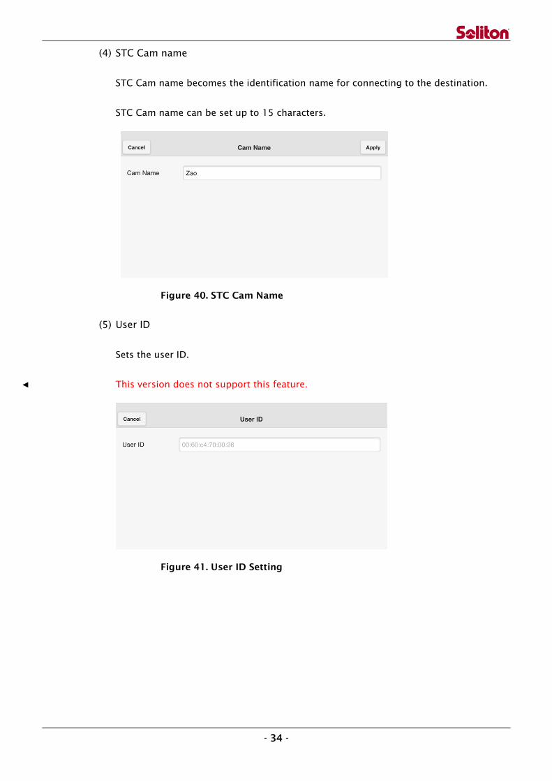
(4) STC Cam name
STC Cam name becomes the identification name for connecting to the destination.
STC Cam name can be set up to 15 characters.
Figure 40. STC Cam Name
(5) User ID
Sets the user ID.
This version does not support this feature.
Figure 41. User ID Setting
- 35 -
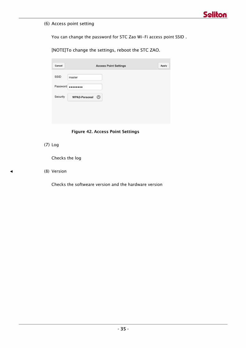
(6) Access point setting
You can change the password for STC Zao Wi-Fi access point SSID .
[NOTE]To change the settings, reboot the STC ZAO.
Figure 42. Access Point Settings
(7) Log
Checks the log
(8) Version
Checks the softweare version and the hardware version

- 36 -
7 STC HDView
The receiver machine comes equipped with the recommended Intel® PC/AT compatible
computer and Blackmagic Design® video output card.
Figure 43. STC HDView Connection
7.1 Requirements for Receiver
Network Interface
A fixed line and a global IP address are required.
* Smart-telecaster Zao uses UDP Port number 31114 for both inbound and outbound
transmission, and UDP Port number 31115, 31116, 31117, 31118 for inbound
transmission. You may also set Receiver under network router. In this case, a NAT
configuration with Port Forwarding for UDP Port numbers 31114 to 31118 is required.
Output:(Integrated by Soliton Systems)
Blackmagic Design® DeckLink Quad
STC HDView receives live video and audio on each channel and outputs to 4 ports of the
DeckLink Quad. The following is the correlation of channel and output.
Channel 1 → HD-SDI/SD-SDI Out1
Channel 2 → HD-SDI/SD-SDI Out2
Channel 3 → HD-SDI/SD-SDI Out3
Channel 4 → HD-SDI/SD-SDI Out4

- 37 -
Figure 44. Output Card Port
Figure 45. Rear Side of Workstation
Workstation
Rear side
DIN(Male) Connectors
DIN-BNC Conversion cable is included with product

- 38 -
7.2 Startup
When you power on the Receiver machine, STC HDView starts automatically.To start STC
HDView manually, click ”STC HDView” icon on Desktop, or extend“Smart-telecaster HD
(MultiLink)” from Programs Menu and click on “STC HDView ML.” STC HDView starts up with the
following main screen.
7.2.1 Main screen
Figure 46. STC HDView Main Screen
Figure 47. STC HDView Main Screen (Tag Details)
(6) (7) (8) (9)

- 39 -
(1) Destination Button
Calls selected Destination Screen.
This version does not support this feature.
(2) Destination Display
Displays destination’s name and IP address.
(3) Connect Button
Connects a destination.
If you are connecting from Receiver you will need at least one network connection (e.g.
wireless LAN) other than dial-up. If Receiver is on Live mode, then a live transmission will be
started. However, a destination not stored in the list cannot be connected.
This version does not support this feature.
(4) Disconnect Button
Disconnects destination.
(5) Channel Indicator
Shows connected channel number.
(6) Network
Selects to display each transmitter network connection status. It also displays connection
speed numerically and graphically.
(7) Status
Selects to display message status of STC HDView.
(8) Audio
In general, the audio of STC HDView is transmitted to all connected transmitter channels.
If Audio mode is turned to OFF, both audio of Transmitter and Receiver on its channel will be
disconnected.
Example: When Audio mode is turned ON for all channels, audio of STC HDView will be
transmitted to all channels.
If Audio mode is turned ON for Channel 1, NO audio is transmitted to channel 1, but
transmitted continually to channel 2 through 4.
(9) Settings
Displays Resolution, Bitrate, Frame Rate, Codec, Delay, Audio, Auto-Record status during
live broadcasting.
(10) Encryption Icon

- 40 -
When a live broadcast is transmitted in encryption mode, the icon is displayed.
(11) Preview Screen
Displays live broadcasting video.
(12) SDI Output Button
When video transmitted to Receiver and the SDI output environment is available, this button
turns Blue.
Each of Output equipment configurations follows:
① Integrated with Blackmagic Design® Decklink Quad video board:
All channels can output video simultaneously and turn blue in color. Audio
and video are output at simultaneously.
② Integrated with others video board:
Only one of 4 channels is able to output video at a time. The SDI output icon
turns blue when selected.
③ When without video board:
All SDI output icons are grayed out and not selectable.
(13) Preset Button
You may register your desired preset of STC HDView settings.
When you click on a preset button, all registered settings will be applied immediately, and
the selected preset button turns green.
(14) Settings Button
Displays Edit Settings dialog of each channel.
(15) Bitrate
Displays numbers of video data rates, which also means displaying the level of
communication amount on current connected bandwidth.
(16) Frame Rate
Displays frame rate.
(17) Status Indicator [ RECV、SEND、FILE ]
When transmission has connected, the connection Status blinks.
(18) Transmitter Audio Indicator[ Cam Audio indicator ]
① Microphone Volume
Remotely controls the transmitter’s MIC volume. Move the slide bar to the left for
lower volume, right for higher volume. Slide the bar all the way left to stop audio
between Transmitter and Receiver. All communication bandwidth will then be allocated

- 41 -
for Video transmitting.
② Audio Level
Displays the transmitter’s audio level. When audio mode is set to Stereo, the upper is
left audio level and lower is right audio level. When the audio mode is set as mono,
upper and lower are same audio level.
(19) Settings Display
During Live broadcasting, displays each variable of Bitrate, Frame Rate, Resolution and
Delay.
(20) Static Picture Button
The ability to capture a still picture is not available in STC Zao, but is available in the old
version of STC.
(21) Record Button
The record feature is not available in STC Zao, but is available in the old version of STC.
(22) Receiver Indicator [ View Audio indicator ]
① MIC Icon
In the event of a MIC input error, an X mark will be shown on top of the icon.
② MIC Volume
To adjust MIC volume for audio input, move the slide bar to left for lower record level
and right for higher record level.
③ Speaker Icon
In the event of a Speaker output error, an X mark will be shown.
④ Speaker Volume
To adjust the audio play application volume, move slide bar to left for lower volume
and right for higher volume.
⑤ Audio Level
Displays input audio level of STC HDView. When in Stereo mode, upper is left level and
lower is right level. When in MONO mode, upper and lower will be the same level.
(23) Common Settings Button
Displays the Edit Dialog of Common Settings.
(24) Finish Button
Finish application.

- 42 -
7.3 Audio Input/Output
STC HDView’s Input/Output is designed to use Windows default playback/recording devices. If
you are changing input sources, connect your recording device, select the Windows default
device and then start up STC HDView.
Also, if you want to use audio via an external audio board, this application designed to use
external output board automatically. You should set the Windows default device to be other than
external output board.
*The Receiver computer is shipped with a video/audio output board installed and Windows
Playback device disabled. The output board (Blackmagic Design® DeckLink Quad) is set as the
default. If you change the default back to Windows Playback device, remember to reset the
default to the output board device again before using the Receiver program. Otherwise there
will be no audio output during transmission.
If you need to reinstall Windows OS, this application is set to use an external output board, so
set Windows default playback devices to use other than an external output board.
Start STC HDView up, open Volume Mixer in Task tray then set System Sound to 0. This step is
only needed once. System Sound is suppressed when STC HDView is running.

- 43 -
7.4 Edit Settings
Edit audio and video settings when Transmitter and Receiver are connected. Each setting
dialogue is distinct, so you must configure every channel.
Figure 48. STC HDView Setting Screen
Figure 49. STC HDView Serial Settings Screen
(12)
① ②

- 44 -
(1) Bitrate[ Bitrate ]
Communication bandwidth.
[Note] STC Zao’s maximum is 10Mbps, compared with 8Mbps previously.
(2) Framerate[ Framerate ]
Specifies Framerate.
(3) Hi-Quality[ Hi-Quality ]
When checked, the Hi-Quality encode mode is used. In Hi-Quality mode, you can get
better-quality video without increasing the video bitrate.
(4) Resolution[ Resolution ]
Set Resolution for Live broadcasting. Each resolution setting is shown in following tables.
[Note] You will need 4 RAM memory modules installed to output 4 channels
simultaneously. If you are upgrading from the current system, you may need
to expand memory.
If the settings value is Middle and the Transmitter is STC Zao, the resolution may
change depending on settings of “7.5 (2) Framerate.”
If the setting value is Low and the Transmitter is STC Zao, the resolution may change
depending on settings of “7.5 (1) Bitrate.”
【Video input setting: 59.94i or 720/59.94p】
STC Zao HD
Settings Image Quality Resolution
High Full HD 1920 x 1080
Middle Half HD (59.94i) 960 x 1080
Half HD (29.97) 1920 x 540
Low (768k above) Quarter HD 960 x 540
Low (512k below) D1 640 x 360
HD(720p)Video input
Settings Video quality Resolution
High Full 720p 1280 x 720
Middle Half 720p (59.94)
640 x 720 Half 720p (29.97)
Low (over 768k) Quarter 720p 640 x 360
Low (below 512k)
STC Zao SD
Settings Image Quality Resolution
High VGA 720 x 480
Middle Half VGA (59.94i) 360 x 480
Half VGA (29.97) 720 x 240
Low (768k above) CIF 360 x 240
Low (512k below)

- 45 -
iOS
Settings Image Quality Resolution
High Quarter HD 960 x 540
Middle D1 640 x 360
Low
【Video input setting: 50i or 72-/50p】
STC Zao HD
Settings Image Quality Resolution
High Full HD 1920 x 1080
Middle Half HD (50i) 960 x 1080
Half HD (25) 1920 x 540
Low (over 768k) Quarter HD 960 x 540
Low (below 512k) D1 640 x 360
HD(720p)Video input
Settings Video quality Resolution
High Full 720p 1280 x 720
Middle Half 720p (50)
640 x 720 Half 720p (25)
Low (over 768k) Quarter 720p 640 x 360
Low (below 512k)
STC Zao SD
Settings Image Quality Resolution
High VGA 720 x 576
Middle Half VGA (50i) 360 x 576
Half VGA (25) 720 x 288
Low (over 768k) CIF 360 x 288
Low (below 512k)
iOS
Settings Image Quality Resolution
High Quarter HD 960 x 540
Middle D1 640 x 360
Low
All resolution settings may be changed when no video is being transmitted. However,
during receiving video transmission, settings depend on image capture type. Either only SD
or HD setting is available.
If settings have changed during video transmission, the change will still be activated after
the video has been disconnected
(5) Delay[ Delay ]
Sets the delay buffering for Transmitter. The value range is from 240msec to 30000msec.
By specifying delay buffering settings, the received video transmission will not be played
immediately. Instead, the transmission will be delayed by a specified time, reducing the
disturbance caused by the frame update interval.

- 46 -
* Suggested settings chart for Transmitter.
Wired LAN connection 240msec more
4G Connection 720msec more
3G Connection 1200msec more
Satellite (BGAN) connection 4000msec more
When transmitting with bonding multiple connections, set to match the slower
connection.
In addition, due to heavy traffic or poor signal situations, the network transmission
might be unstable. In this case, stop moving and keep the camera still for a while. You
also can increase the stability by extending the delay.
(6) Presets[ Presets ]
In STC HDView, you can register any of the settings as a preset.
① Preset Button
By clicking Preset button, it becomes highlighted in
green. All registered settings in dialogues will be
collectively changed.
[NOTE] The preset name set in registration will be
displayed.
② Preset Register Button
By clicking this button, the preset dialogue will be
displayed.
Figure 49. STC HDView Preset Screen
Specify the Preset name, then click Save button. Current settings will be registered
as preset and become selected.
By clicking the Cancel button, the preset register will be canceled.
Note that Preset Name is also reflected in the Preset Button on the main screen.
When Preset is selected, the button becomes green.
The preset selected state will be canceled after any of settings have been changed.
(7) Forwarding Received File[ Forwarding received file ]
This feature is not embedded in STC HDView
①
②

- 47 -
(8) Audio Frequency and Mode[ Audio frequency and mode ]
Specifies Audio Sampling Rate, Stereo/MONO and Audio Bandwidth.
Audio Frequency
Sets sampling rate for audio send/receive.
[NOTE] When connected with iOS ML, it is fixed to 22050Hz.
Audio Channel
Set Stereo or MONO for audio input channel.
Audio Band [ AudioBand ]
Configures audio band (Kbps)
The available audio band, frequency and channels can be set in the following
range.
Audio
Frequency
Stereo (Kbps) MONO (Kbps)
8000Hz 11.71 ~ 62.50 7.81 ~ 41.01
11025Hz 15.62 ~ 85.93 11.71 ~ 48.82
16000Hz 23.43 ~ 167.96 15.62 ~ 97.65
22050Hz 29.29 ~ 167.96 15.62 ~ 87.89
48000Hz 43.94 ~ 488.28 31.25 ~ 234.37
(9) Audio Source Selection [ Audio source ]
Select Left or Right when audio channel in MONO mode.
① Left Select Left channel to use as MONO audio input.
② Right Select Right channel to use as MONO audio input.
(10) Control Transmitter Line[ Line stop ]
In STC HDView, there is a Purge feature, which you can individually Pause and Reconnect the
network connection with Transmitter. (This feature is available only when connected
multiple connections.)
To pause the connection, check the desired connection and click the OK button.
To reconnect, uncheck the connection and click the OK button.
The Purge feature can be operated while maintaining a live broadcast. This is useful for
temporarily disconnecting a lower bandwidth connection caused by moving the
Transmitter’s location rapidly. It also can be useful for redialing (disconnect reconnect).
(11) Others[ Others ]
① Encryption[ Encryption ]
Encrypts data for transmission.
② Automatic Recording[ Automatic recording ]
[NOTE] This feature is not available in STC Zao version, but it is available in the
previous version.

- 48 -
③ Mix Recording with Local Audio[ Mixing local audio on recording ]
[NOTE] This feature is not available in STC Zao version, but it is available in the
previous version.
(12) Serial Port Tunneling
The feature is not available in STC Zao.

- 49 -
7.5 Common settings
Configure Authentication Code with Transmitter.
Figure 50 STC HDView Common Settings Screen
Authentication Setting[ Authentication setting ]
(1) Authentication Code[ Authentication code ]
You can set the code for connection authentication for the Transmitter.
The authentication code can be set using up to 30 alphanumeric characters. (The code you
enter will be displayed as *.)
This feature is active only when Authentication is flagged.
(2) Authentication Validated Flag[ Validation ]
When ON checked :Enable Authentication Code
When OFF checked :Unable Authentication Code
* When the Authentication feature is enabled, only transmitters with same authentication
code can be connected. If the authentication code is different, a transmitter cannot be
connected with STC HDView.
Other settings[ Other settings ]
(3) Confirm Bluetooth Device[ Confirm Bluetooth connection ]
This feature is not available in this version.
(4) Product Serial[ Product Serial ID ]
(5) Serial ID[ Serial ID ]
Displays registered serial ID.