venturi air sprayers - gearmore, inc. - home€¦ · · 2018-02-142 1 20.754.101 tie rod d.20 3 1...
TRANSCRIPT

VENTURI AIRSPRAYERS
Form: P45N400GBookRev2012.indd
Parts Manual For Model P45N1-400-G
3-Point Mount
June 2012 (Rev.)

TABLE OF CONTENTS
SECTION DESCRIPTION ................................................ PAGE 1 Introduction ....................................................................... 1 1.1 Purchaser’s Responsibility .............................................. 1 1.2 Serial Number Information ............................................ 1
2 Replacement Parts .....................................................2 - 29 2.1 Main Frame Assembly ................................................. 2-3 2.2 Main Tank Assembly .................................................... 4-5 2.3 Hand Cleaner Tank ......................................................... 6 2.4 400 Lt. Tank .................................................................... 7 2.5 Regulation Valve ............................................................. 8 2.6 Fan Assembly .................................................................. 9 2.7 Fan Support & Belt Tensioner ................................. 10-12 2.8 Clutch & Pulley ............................................................. 13 2.9 Clutch Shaft ................................................................... 14 2.10 Liquid Flow Path Manual ........................................ 15-17 2.11 Pump Assembly ........................................................ 18-19 2.12 Remote Control .............................................................. 20 2.13 Optional Electro Valve Assy .................................... 21-22 2.14 Manual Distributor .................................................. 23-24 2.15 Belt Assembly ................................................................ 25 2.16 Dial-A-Rate .................................................................... 26 2.17 Driveline......................................................................... 27
3 Limited Warranty ............................................................ 28

1 INTRODUCTION
This manual contains parts diagrams and replacement parts lists. Do not modify the equipment in any way. Unauthorized modifi cation may impair the function and/or safety and could affect the life of the equipment.
It is the responsibility of the owner to make sure the machine is maintained properly, and that all parts are in working order.
Where replacement parts are necessary for periodic maintenance and servicing, genuine factory replacement parts MUST be used to restore your equipment to original specifi cations. The manufacturer will not be respon-sible for injuries or damages caused by use of unapproved parts and/or accessories.
The manufacturer reserves the right to make improvements to the machinery and parts at any time and at their discretion.
OPERATOR ORIENTATION - The directions left, right, front and rear, are as seen from the driver's seat and facing in the direction of travel.
1.1 PURCHASER’S RESPONSIBILITY
It is the responsibility of the purchaser and/or operator to.....
● Inspect the equipment and replace or repair any parts that are damaged or worn which under continued operation would cause damage, wear to other parts, or cause a safety hazard.
● Return the equipment or parts to the authorized dealer, from where it was purchased, for service or replacement of defective parts that are covered by warranty. (The factory may inspect equipment or parts before warranty claims are honored.)
● Payment of all costs incurred by the dealer for traveling to or transporting the equipment for warranty inspection and or claims.
1.2 MODEL / SERIAL NUMBER
NAME: ____________________________________
PURCHASED FROM: ____________________________
DATE OF PURCHASE: ___________________________
MODEL NUMBER: ______________________________
SERIAL NUMBER: ______________________________
1

2
2 REPLACEMENT PARTS2.1 MAIN FRAME ASSEMBLY

2 REPLACEMENT PARTS (CONTINUED)
3
2.1 MAIN FRAME ASSY.
REF. QTY. PART NO. DESCRIPTION 1 4 D0.22.5588F Nut M22 x 1.5 2 1 20.754.101 Tie Rod D.20 3 1 20.434.000 Fixing Cover 4 1 40.227.000 Front Plate 5 1 CP.006.040I Pin D.6 Lg.40 6 1 04.076.000 Pin 7 1 02.278.030 Chain 8 2 04.064.000 Pin Power Lift 9 1 40.226.000 Frame 10 1 20.744.000 Fixing Tank Plate 11 9 RP.008.000 Washer D.8 12 1 02.278.045 Chain 13 3 RD.022.000 Tab Washer D.22 14 1 40.000.000 Bumper 15 1 20.737.101 Plate For Rod M20 16 1 20.743.000 Inspection Plate 17 4 TE010.070T Bolt TE 10 x 70 18 2 TE.008.070 Bolt TE M8 x 70 19 1 20.778.000 Bushing 20 1 00.100.004 Split Pin D.4 21 5 RP.008.024 Washer D.8 x 24 22 2 TE.008.035T Bolt TE M8 x 35 23 2 TE.008.016T Bolt TE M8 x 16 24 5 TE.008.020T Bolt TE 8 x 20 25 3 D0.08.5588G Nut M8 26 3 TCC.06.16 Cross Slotted Screw M6 x 16 27 8 RP.010.000 Washer D.10 28 4 D0.10.5587G Nut M10 29 1 20.791.000 Plate 30 1 40.237.000 Wrench M32 31 1 20.861.000 Disengaged Protection Disk

4
2 REPLACEMENT PARTS (CONTINUED) 2.2 MAIN TANK
2 REPLACEMENT PARTS (CONTINUED)
5
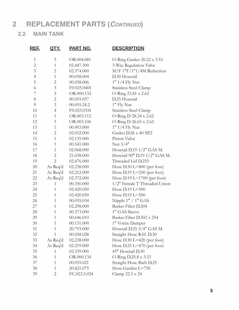
2.2 MAIN TANK
REF. QTY. PART NO. DESCRIPTION 1 3 OR.004.081 O-Ring Gasket 20.22 x 3.53 2 1 02.447.300 3-Way Regulation Valve 3 2 02.374.000 M/F 1"F/1"1/4M Reduction 4 1 00.058.004 D.30 Hosetail 5 2 00.058.006 1" 1/4 Fly Nut 6 3 F0.025.040I Stainless Steel Clamp 7 3 OR.000.132 O-Ring 23.81 x 2.62 8 2 00.055.037 D.25 Hosetail 9 3 00.055.24.2 1" Fly Nut 10 4 F0.023.035I Stainless Steel Clamp 11 1 OR.003.112 O-Ring D 28.24 x 2.62 12 3 OR.003.106 O-Ring D 26.65 x 2.62 13 1 00.493.000 1" 1/4 Fly Nut 14 2 02.032.000 Gasket D.26 x 40 SP.2 15 1 02.135.000 Piston Valve 16 1 00.541.000 Nut 3/4" 17 1 02.068.000 Hosetail D.19 1/2" GAS M. 18 2 21.038.000 Hosetail 90° D.19 1/2" GAS M. 19 2 02.476.000 Threaded Lid D.255 20 As Req'd 02.238.000 Hose D.30 L=800 (per foot) 21 As Req'd 02.212.000 Hose D.19 L=250 (per foot) 22 As Req'd 02.372.000 Hose D.19 L=1700 (per foot) 23 1 00.350.000 1/2" Female T Threaded Union 24 1 02.420.050 Hose D.19 L=500 25 1 02.420.050 Hose D.19 L=500 26 1 00.055.034 Nipple 1" / 1" GAS 27 1 02.298.000 Basket Filter D.204 28 1 00.373.000 1" GAS Sleeve 29 1 00.646.010 Basket Filter D.302 x 254 30 1 00.131.000 1" Vortix Damper 31 1 20.793.000 Hosetail D.25 3/4" GAS M. 32 1 00.058.028 Straight Hose R.H. D.30 33 As Req'd 02.238.000 Hose D.30 L=420 (per foot) 34 As Req'd 02.219.000 Hose D.25 L=470 (per foot) 35 1 02.339.000 45° Hosetail D.30 36 1 OR.000.134 O-Ring D.25.8 x 3.53 37 1 00.055.021 Straight Hose Barb D.25 38 1 20.821.075 Hose Garden L=750 39 2 FC.022.5.024 Clamp 22.5 x 24

6
2 REPLACEMENT PARTS (CONTINUED) 2.3 HAND CLEANER TANK 40.219.002
REF. QTY. PART NO. DESCRIPTION 1 1 K.LAV.04.P01 Hand Cleaner Tank Kit 2 1 02.477.000.A Threaded Ring Gasket D.255 3 1 02.477.000 Threaded Ring D.255 4 16 TAS.04.2.025 Self Threading Screw 4.2 x 25 5 1 20.787.000 Hinged Tank Lid 6 1 20.787.000.L Gasket
7
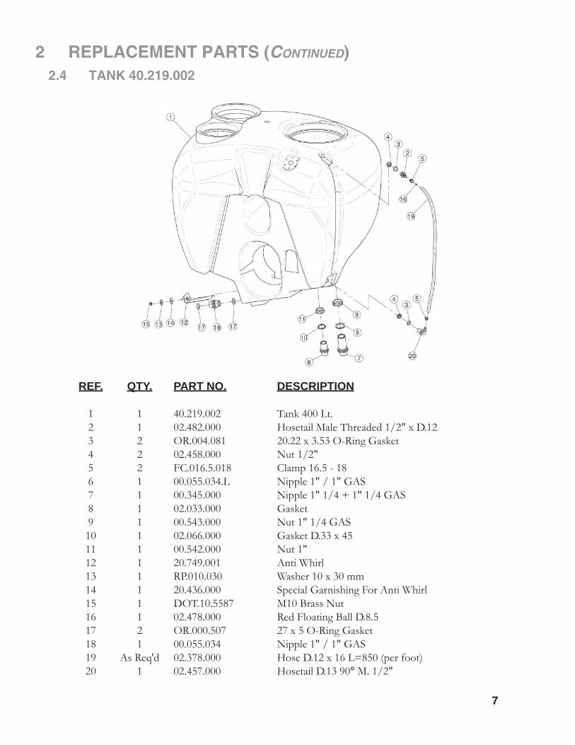
2 REPLACEMENT PARTS (CONTINUED)2.4 TANK 40.219.002
REF. QTY. PART NO. DESCRIPTION 1 1 40.219.002 Tank 400 Lt. 2 1 02.482.000 Hosetail Male Threaded 1/2" x D.12 3 2 OR.004.081 20.22 x 3.53 O-Ring Gasket 4 2 02.458.000 Nut 1/2" 5 2 FC.016.5.018 Clamp 16.5 - 18 6 1 00.055.034.L Nipple 1" / 1" GAS 7 1 00.345.000 Nipple 1" 1/4 + 1" 1/4 GAS 8 1 02.033.000 Gasket 9 1 00.543.000 Nut 1" 1/4 GAS 10 1 02.066.000 Gasket D.33 x 45 11 1 00.542.000 Nut 1" 12 1 20.749.001 Anti Whirl 13 1 RP.010.030 Washer 10 x 30 mm 14 1 20.436.000 Special Garnishing For Anti Whirl 15 1 DOT.10.5587 M10 Brass Nut 16 1 02.478.000 Red Floating Ball D.8.5 17 2 OR.000.507 27 x 5 O-Ring Gasket 18 1 00.055.034 Nipple 1" / 1" GAS 19 As Req'd 02.378.000 Hose D.12 x 16 L=850 (per foot) 20 1 02.457.000 Hosetail D.13 90° M. 1/2"

8
2 REPLACEMENT PARTS (CONTINUED) 2.5 REGULATION VALVE 02.447.300
REF. QTY. PART NO. DESCRIPTION 1 1 TE.008.025I INOX 8 x 25 Screw 2 1 RP.008.024I INOX Washer D.8 x 24 3 1 02.447.010 Regulation Valve Knob 4 1 02.447.011 Spring 5 4 TE.006.060I INOX M6 x 60 TE Screw 6 1 02.447.012 Upper Flange 7 6 RP.006.000I INOX Washer D.6 8 2 TE.006.045I INOX M6 x 45 Screw 9 1 02.447.013 Valve Pin 10 2 OR.003.068 O-Ring Gasket 17.12 x 2.62 11 1 02.447.005 Special O-Ring for Gate 2447 12 2 OR.003.193 O-Ring Gasket 48.89 x 2.62 13 1 02.447.001 Body for Regulation Valve 14 6 DO.06.5588GI INOX M6 6S Nut 5588
2 REPLACEMENT PARTS (CONTINUED)
9
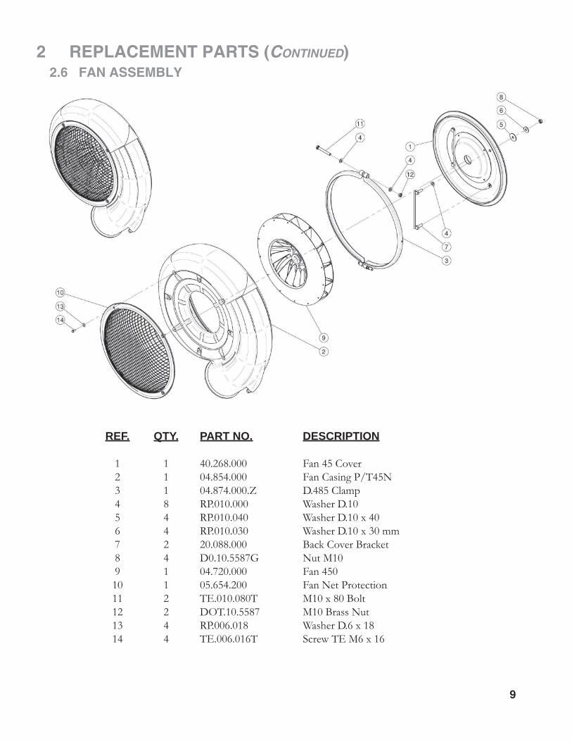
2.6 FAN ASSEMBLY
REF. QTY. PART NO. DESCRIPTION 1 1 40.268.000 Fan 45 Cover 2 1 04.854.000 Fan Casing P/T45N 3 1 04.874.000.Z D.485 Clamp 4 8 RP.010.000 Washer D.10 5 4 RP.010.040 Washer D.10 x 40 6 4 RP.010.030 Washer D.10 x 30 mm 7 2 20.088.000 Back Cover Bracket 8 4 D0.10.5587G Nut M10 9 1 04.720.000 Fan 450 10 1 05.654.200 Fan Net Protection 11 2 TE.010.080T M10 x 80 Bolt 12 2 DOT.10.5587 M10 Brass Nut 13 4 RP.006.018 Washer D.6 x 18 14 4 TE.006.016T Screw TE M6 x 16
10
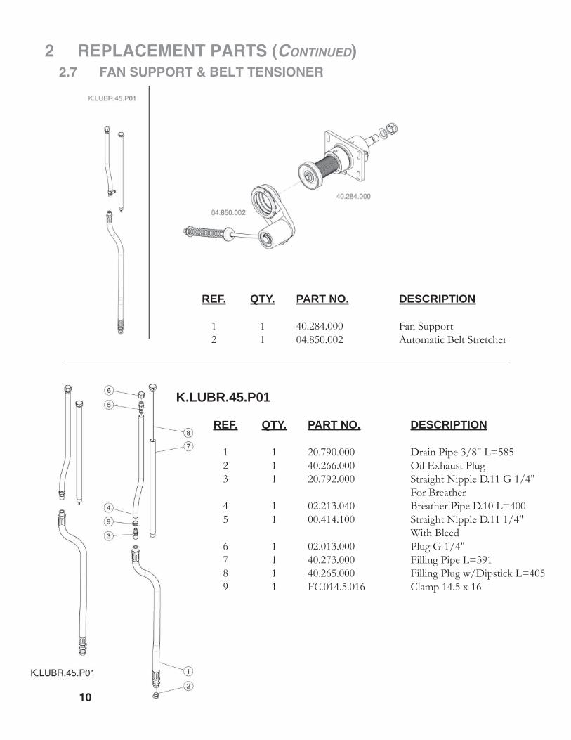
2 REPLACEMENT PARTS (CONTINUED) 2.7 FAN SUPPORT & BELT TENSIONER
REF. QTY. PART NO. DESCRIPTION 1 1 40.284.000 Fan Support 2 1 04.850.002 Automatic Belt Stretcher
K.LUBR.45.P01
REF. QTY. PART NO. DESCRIPTION 1 1 20.790.000 Drain Pipe 3/8" L=585 2 1 40.266.000 Oil Exhaust Plug 3 1 20.792.000 Straight Nipple D.11 G 1/4" For Breather 4 1 02.213.040 Breather Pipe D.10 L=400 5 1 00.414.100 Straight Nipple D.11 1/4" With Bleed 6 1 02.013.000 Plug G 1/4" 7 1 40.273.000 Filling Pipe L=391 8 1 40.265.000 Filling Plug w/Dipstick L=405 9 1 FC.014.5.016 Clamp 14.5 x 16

2 REPLACEMENT PARTS (CONTINUED)
11
2.7 FAN SUPPORT & BELT TENSIONER (continued)
REF. QTY. PART NO. DESCRIPTION 1 1 40.260.000 Housing, Fan Support 2 1 40.271.054 Shaft With Pulley D.54 J32 3 1 40.262.000 Spacer Fan Support 4 1 I0.062.000 Internal I.62 Circlip 5 1 40.263.000 Seal Spacer 6 1 21305 Bearing 7 1 22206 Bearing 8 2 40x62x10 Oil Seal 40 x 62 x 10 9 1 40.267.000 Side Fan Cover 10 1 L.08.07.35 8 x 7 x 35 Tang 11 1 DA.022.0BF Self-Locking Nut M22 x 1.5 12 1 RP.022.000 Washer D.22 13 1 20.789.000 Male/Female 90° Elbow 14 1 40.264.000 Spacer 15 1 02.723.003 Pulley for Pump D.78 x 1 3V 16 1 RP.010.040 Washer D.10 x 40 17 1 RP.010.030 Washer D.10 x 30 mm 18 1 TE.010.025FT Bolt TE M10 x 25 19 1 SE.006.020 Spring Pin D.6 x 20 20 1 02.723.001 Special Washer 3 mm
FAN SUPPORT 40.284.000

12
2 REPLACEMENT PARTS (CONTINUED) 2.7 FAN SUPPORT & BELT TENSIONER (continued)
REF. QTY. PART NO. DESCRIPTION 1 1 D0.12.5587G M12 Nut 2 1 04.583.000 Special Screw 3 1 47125 External D.25 Circlip 4 2 04.585.000 Anti-Dust Cover 5 2 6205-2RS Bearing 6205-2RS 6 1 RP.019.000 Washer D.19 7 1 04.578.000 Spring 8 1 04.083.000 Roller for Belt Stretcher 9 1 04.084.000 Spacer for Belt Stretcher 10 2 47252 Internal D.52 Circlip 11 1 20.260.000 Special Washer D.12 12 1 05.726.000 Belt Stretcher Fork 13 1 04.099.000 Nut 80 x 2 14 1 04.835.000 Belt Stretcher Pin 15 1 MB.016.000 Tooth Lock Washer MB 16 16 1 04.095.000 Belt Stretcher Housing 17 1 47180 External D 80 Circlip 18 1 KM.005.000 Nut KM5 19 1 04.593.000 Pin 20 1 00.100.002 Clip
BELT TENSIONER 04.850.002

2 REPLACEMENT PARTS (CONTINUED)
13
2.8 CLUTCH & PULLEY
REF. QTY. PART NO. DESCRIPTION 1 1 04.094.01C Clutch Assembly 2 1 00.450.J32 Pulley 3 1 04.719.000 Gasket 4 1 04.066.000 Body 5 1 03.701.000 Rotor 6 1 ID.010.001 Grease Nipple 7 4 TE.012.040F Bolt M12 x 40 8 4 RD.012.000 Tab Washer D.12 9 2 02.502.002 Key 10 2 02.502.001 Spring
14
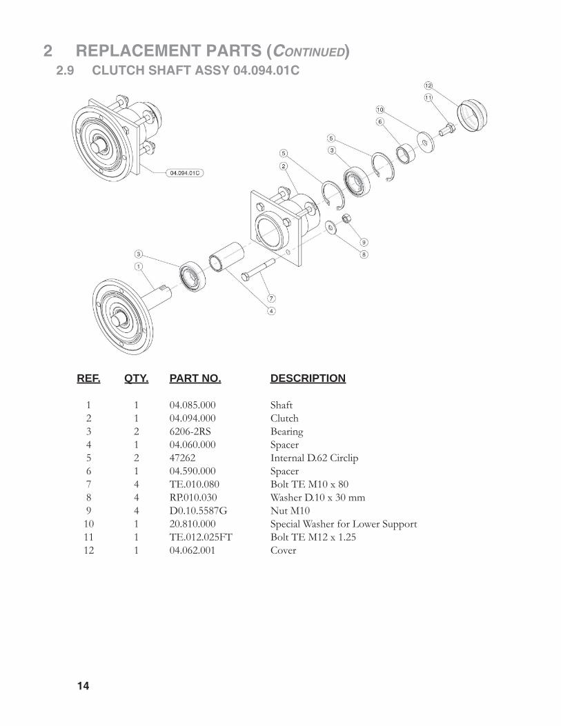
2 REPLACEMENT PARTS (CONTINUED) 2.9 CLUTCH SHAFT ASSY 04.094.01C
REF. QTY. PART NO. DESCRIPTION
1 1 04.085.000 Shaft 2 1 04.094.000 Clutch 3 2 6206-2RS Bearing 4 1 04.060.000 Spacer 5 2 47262 Internal D.62 Circlip 6 1 04.590.000 Spacer 7 4 TE.010.080 Bolt TE M10 x 80 8 4 RP.010.030 Washer D.10 x 30 mm 9 4 D0.10.5587G Nut M10 10 1 20.810.000 Special Washer for Lower Support 11 1 TE.012.025FT Bolt TE M12 x 1.25 12 1 04.062.001 Cover

2 REPLACEMENT PARTS (CONTINUED)
15
2.10 LIQUID FLOW PATH MANUAL
16
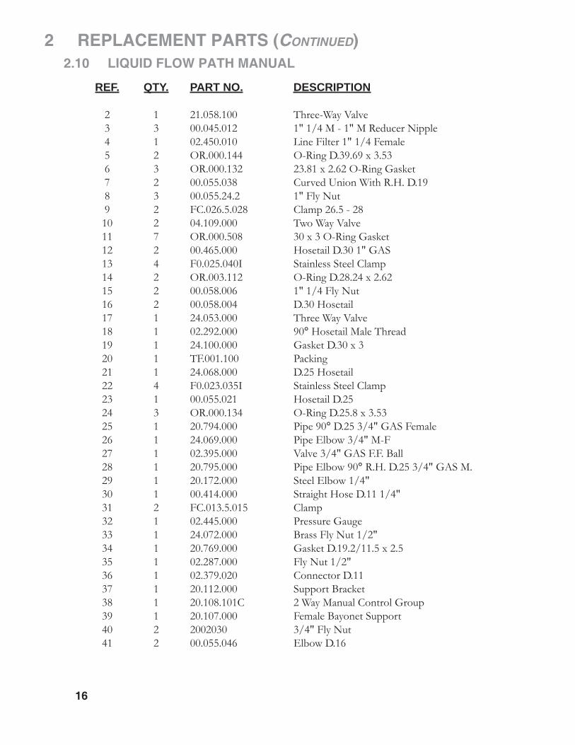
2 REPLACEMENT PARTS (CONTINUED) 2.10 LIQUID FLOW PATH MANUAL
REF. QTY. PART NO. DESCRIPTION 2 1 21.058.100 Three-Way Valve 3 3 00.045.012 1" 1/4 M - 1" M Reducer Nipple 4 1 02.450.010 Line Filter 1" 1/4 Female 5 2 OR.000.144 O-Ring D.39.69 x 3.53 6 3 OR.000.132 23.81 x 2.62 O-Ring Gasket 7 2 00.055.038 Curved Union With R.H. D.19 8 3 00.055.24.2 1" Fly Nut 9 2 FC.026.5.028 Clamp 26.5 - 28 10 2 04.109.000 Two Way Valve 11 7 OR.000.508 30 x 3 O-Ring Gasket 12 2 00.465.000 Hosetail D.30 1" GAS 13 4 F0.025.040I Stainless Steel Clamp 14 2 OR.003.112 O-Ring D.28.24 x 2.62 15 2 00.058.006 1" 1/4 Fly Nut 16 2 00.058.004 D.30 Hosetail 17 1 24.053.000 Three Way Valve 18 1 02.292.000 90° Hosetail Male Thread 19 1 24.100.000 Gasket D.30 x 3 20 1 TF.001.100 Packing 21 1 24.068.000 D.25 Hosetail 22 4 F0.023.035I Stainless Steel Clamp 23 1 00.055.021 Hosetail D.25 24 3 OR.000.134 O-Ring D.25.8 x 3.53 25 1 20.794.000 Pipe 90° D.25 3/4" GAS Female 26 1 24.069.000 Pipe Elbow 3/4" M-F 27 1 02.395.000 Valve 3/4" GAS F.F. Ball 28 1 20.795.000 Pipe Elbow 90° R.H. D.25 3/4" GAS M. 29 1 20.172.000 Steel Elbow 1/4" 30 1 00.414.000 Straight Hose D.11 1/4" 31 2 FC.013.5.015 Clamp 32 1 02.445.000 Pressure Gauge 33 1 24.072.000 Brass Fly Nut 1/2" 34 1 20.769.000 Gasket D.19.2/11.5 x 2.5 35 1 02.287.000 Fly Nut 1/2" 36 1 02.379.020 Connector D.11 37 1 20.112.000 Support Bracket 38 1 20.108.101C 2 Way Manual Control Group 39 1 20.107.000 Female Bayonet Support 40 2 2002030 3/4" Fly Nut 41 2 00.055.046 Elbow D.16

17
2 REPLACEMENT PARTS (CONTINUED) 2.10 LIQUID FLOW PATH MANUAL (continued)
REF. QTY. PART NO. DESCRIPTION
42 2 02.349.000 17 x 23 x 3 Flat Gasket 43 1 obtain locally Zip Tie 44 1 02.278.030 Chain 45 As Req'd 20.852.000 Hose D.30 L=440 (per foot) 46 As Req'd 20.852.000 Hose D.30 L=300 (per foot) 47 As Req'd 20.770.000 Hose D.25 L=370 (per foot) 48 As Req'd 02.211.000 Hose D.16 L=4500 (per foot) 49 As Req'd 02.212.000 Hose D.19 L=4000 (per foot) 50 As Req'd 20.770.000 Hose D.25 L=450 (per foot) 51 As Req'd 02.213.000 Hose D.101 L=1350 (per foot) 52 As Req'd 02.211.000 Hose D.16 L=4500 (per foot) 53 2 FC.021.5.023 Clamp 21.5 - 23 54 2 FC.023.5.025 Clamp 21.5 - 25

18
2 REPLACEMENT PARTS (CONTINUED) 2.11 PUMP ASSEMBLY

2 REPLACEMENT PARTS (CONTINUED)
19
2.11 PUMP ASSEMBY REF. QTY. PART NO. DESCRIPTION 1 1 04.111.022 Pump Cap Chain L=220 2 1 02.120.000 Rapid Thread Cap 3 1 02.130.000 24 x 46 x 3 Rubber Gasket 4 1 02.116.000 Suction Fitting 5 4 RP.006.018 Large Washer d.6 x 18 6 1 OR.003.181 45.69 x 50.93 x 2.62 O-Ring 7 1 02.152.010 Housing 8 2 TM.010.015 M10 x 1.5 Cap 9 17 TC.05.25.85 Cross Slotted Screw M5 x 25 10 1 TF.012.000 Blank Cap 1/2" 11 1 02.179.000 Rubber Gasket 12 1 02.113.000 Three Way Tap 13 4 TE.006.025T Bolt TE M6 x 25 14 4 RP.006.000 Washer D.6 15 8 DOT.06.5587 M6 Brass Nut 16 1 DOT.10.5587 M10 Brass Nut 17 1 02.153.000 CD32 Pump Impeller 18 1 00.085.024CS Mechanical Seal 19 1 02.151.010 Pump Casing 21 1 20.406.000 Special Cover for Pump 22 17 RP.005.000 Washer D.5 23 2 6303-2RS Roller Bearing 24 1 TE.012.040T Bolt TE M12 x 40 25 1 02.155.010 CD32 Pump Shaft 26 1 02.978.000SX Bracket 27 3 D0.08.5588G Nut M8 28 1 02.963.100 Pin Belt Stretcher Pump CD 32 29 1 02.722.000 Bushing 30 2 02.723.001 Special Washer 3 mm 31 1 21.113.000 Washer D.12 x 36 32 1 02.723.002 Pulley for Pump D.82.5 x 1 3V 33 1 02.964.000 CD 32 Pump Spring 34 2 RP.012.000 Washer D.12 35 1 RP.010.030 Washer Large 10 x 30 mm 36 1 20.738.000 Lever M12 for Belt Stretcher 37 1 47247 Internal D.45 Circlip 38 2 L.05.05.10 5 x 5 x 10 Tang 39 17 DOT.05.5587 M5 Brass Nut (5587) 40 1 02.114.000 INOX Special Washer 41 1 DA.010.0BG Self Locking Nut M10 42 1 DA.012.0AG Self Locking Nut M12 43 1 MT.012.000 Washer D.12 44 1 RP.010.001 Washer D.10 INOX 45 1 OR.000.117 13.1 x 18.34 x 2.62 O-Ring Gasket 46 1 D0.10.5588G Nut M10 47 3 RP.008.024 Washer D.8 x 24 48 1 OR.C02.070 OR Cord D.2 L=700
20
2 REPLACEMENT PARTS (CONTINUED)
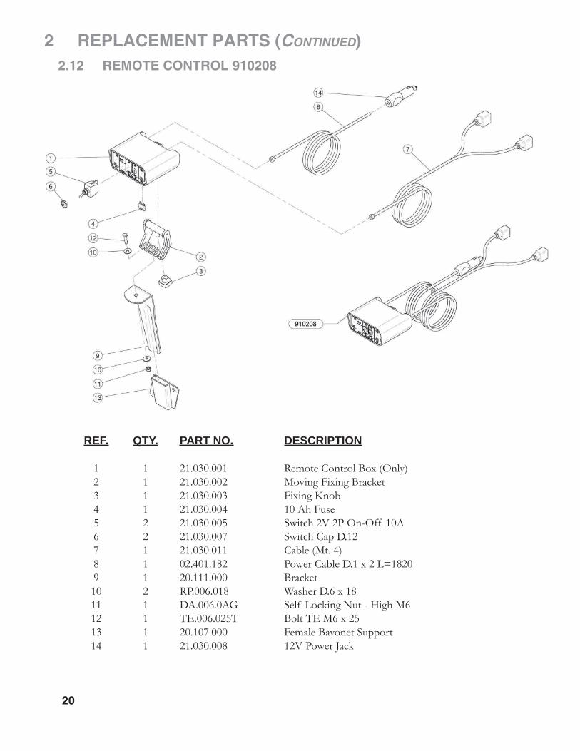
REF. QTY. PART NO. DESCRIPTION
1 1 21.030.001 Remote Control Box (Only) 2 1 21.030.002 Moving Fixing Bracket 3 1 21.030.003 Fixing Knob 4 1 21.030.004 10 Ah Fuse 5 2 21.030.005 Switch 2V 2P On-Off 10A 6 2 21.030.007 Switch Cap D.12 7 1 21.030.011 Cable (Mt. 4) 8 1 02.401.182 Power Cable D.1 x 2 L=1820 9 1 20.111.000 Bracket 10 2 RP.006.018 Washer D.6 x 18 11 1 DA.006.0AG Self Locking Nut - High M6 12 1 TE.006.025T Bolt TE M6 x 25 13 1 20.107.000 Female Bayonet Support 14 1 21.030.008 12V Power Jack
2.12 REMOTE CONTROL 910208
2 REPLACEMENT PARTS (CONTINUED)
21
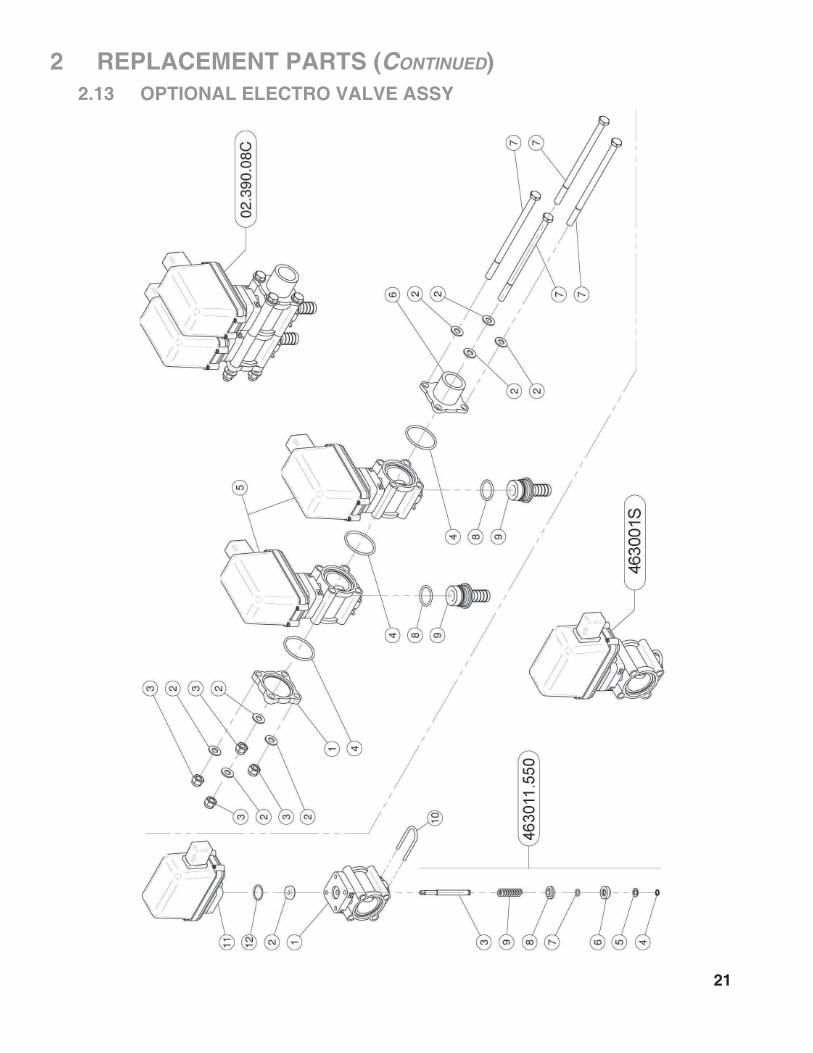
2.13 OPTIONAL ELECTRO VALVE ASSY
22
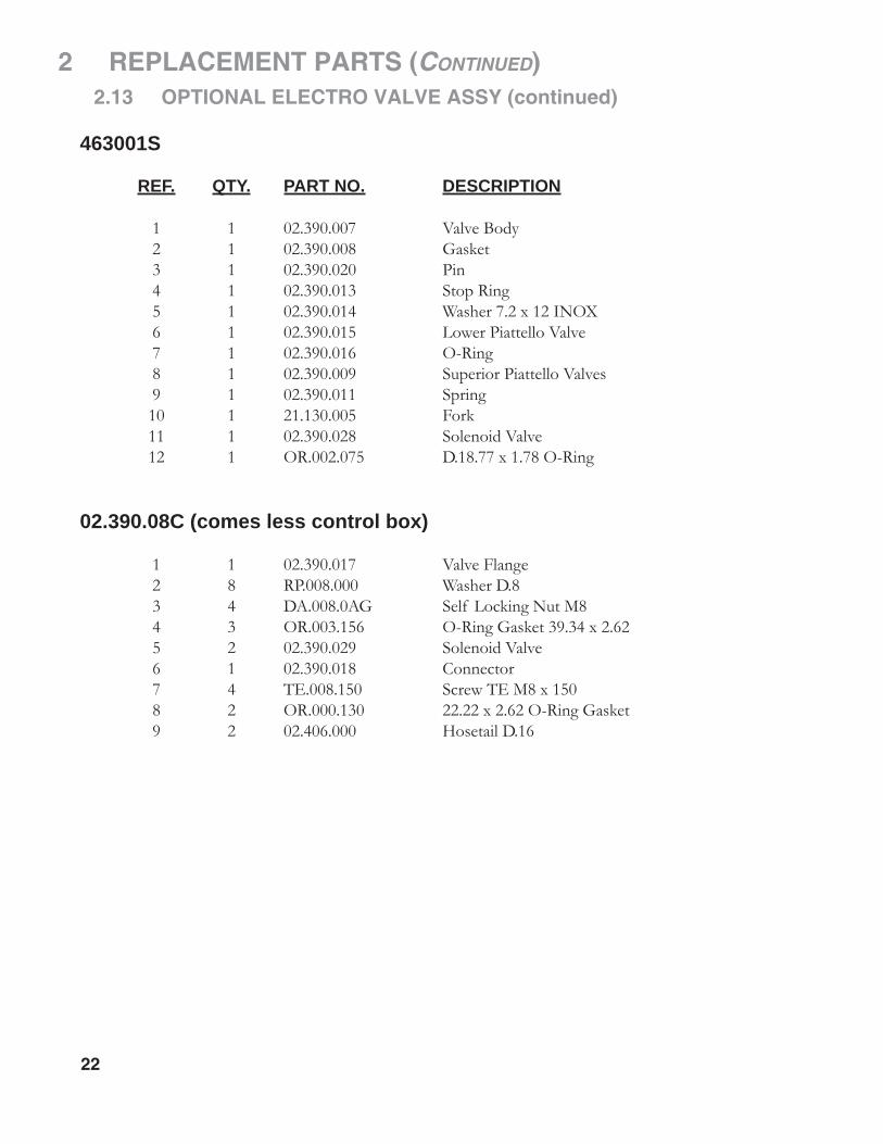
2 REPLACEMENT PARTS (CONTINUED) 2.13 OPTIONAL ELECTRO VALVE ASSY (continued)
463001S
REF. QTY. PART NO. DESCRIPTION 1 1 02.390.007 Valve Body 2 1 02.390.008 Gasket 3 1 02.390.020 Pin 4 1 02.390.013 Stop Ring 5 1 02.390.014 Washer 7.2 x 12 INOX 6 1 02.390.015 Lower Piattello Valve 7 1 02.390.016 O-Ring 8 1 02.390.009 Superior Piattello Valves 9 1 02.390.011 Spring 10 1 21.130.005 Fork 11 1 02.390.028 Solenoid Valve 12 1 OR.002.075 D.18.77 x 1.78 O-Ring
02.390.08C (comes less control box) 1 1 02.390.017 Valve Flange 2 8 RP.008.000 Washer D.8 3 4 DA.008.0AG Self Locking Nut M8 4 3 OR.003.156 O-Ring Gasket 39.34 x 2.62 5 2 02.390.029 Solenoid Valve 6 1 02.390.018 Connector 7 4 TE.008.150 Screw TE M8 x 150 8 2 OR.000.130 22.22 x 2.62 O-Ring Gasket 9 2 02.406.000 Hosetail D.16

2 REPLACEMENT PARTS (CONTINUED)
23
2.14 MANUAL DISTRIBUTOR 20.108.101C
24
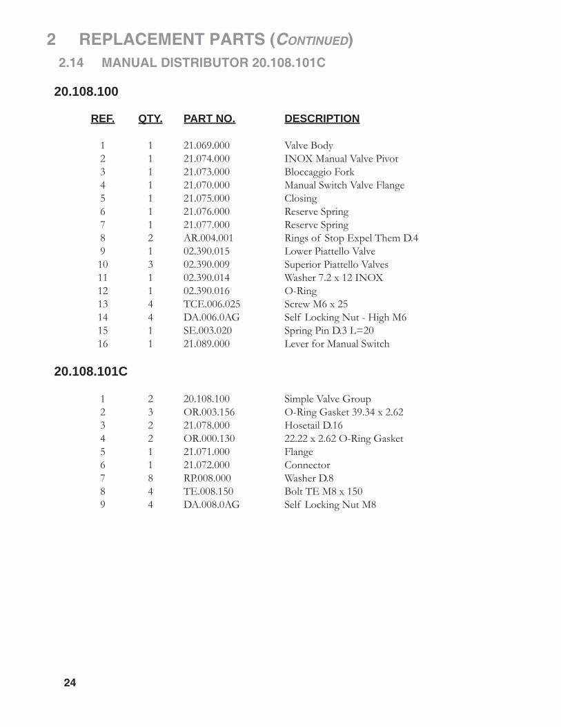
2 REPLACEMENT PARTS (CONTINUED) 2.14 MANUAL DISTRIBUTOR 20.108.101C
20.108.100
REF. QTY. PART NO. DESCRIPTION 1 1 21.069.000 Valve Body 2 1 21.074.000 INOX Manual Valve Pivot 3 1 21.073.000 Bloccaggio Fork 4 1 21.070.000 Manual Switch Valve Flange 5 1 21.075.000 Closing 6 1 21.076.000 Reserve Spring 7 1 21.077.000 Reserve Spring 8 2 AR.004.001 Rings of Stop Expel Them D.4 9 1 02.390.015 Lower Piattello Valve 10 3 02.390.009 Superior Piattello Valves 11 1 02.390.014 Washer 7.2 x 12 INOX 12 1 02.390.016 O-Ring 13 4 TCE.006.025 Screw M6 x 25 14 4 DA.006.0AG Self Locking Nut - High M6 15 1 SE.003.020 Spring Pin D.3 L=20 16 1 21.089.000 Lever for Manual Switch
20.108.101C 1 2 20.108.100 Simple Valve Group 2 3 OR.003.156 O-Ring Gasket 39.34 x 2.62 3 2 21.078.000 Hosetail D.16 4 2 OR.000.130 22.22 x 2.62 O-Ring Gasket 5 1 21.071.000 Flange 6 1 21.072.000 Connector 7 8 RP.008.000 Washer D.8 8 4 TE.008.150 Bolt TE M8 x 150 9 4 DA.008.0AG Self Locking Nut M8

2 REPLACEMENT PARTS (CONTINUED)
25
2.15 BELT ASSEMBLY
REF. QTY. PART NO. DESCRIPTION
6 2 02.945.000 Back Cover Bracket 7 4 RP.012.036 Washer D12 x 36 8 4 D0.12.5587G M12 Nut 9 1 TE.010.060T Bolt TE M10 x 60 10 1 02.736.000 90 G. M10 x 1 Fitting 12 1 02.737.000 Adapter M10 13 1 ID.010.001 Grease Nipple 14 1 C0.500.03V V-Belt 3V500 15 1 C0.650.J32 Drive Belt 650J32

26
2 REPLACEMENT PARTS (CONTINUED) 2.16 DIAL-A-RATE 02.150.000
REF. QTY. PART NO. DESCRIPTION
1 1 02.349.000 17 x 23 x 3 Flat Gasket 2 1 02.117.000 Adaptor Nipple 3 1 2002030 3/4" Fly Nut 4 2 DF.OTT.006 Wing Nut M6 5 2 RP.006.000 Washer D.6 6 2 OR.002.062 D.15.6 x 1.78 OR 7 1 02.148.000 Regulator Disk 8 2 TE.006.030I Bolt M6 x 30 Bolt 9 1 02.147.500 Regulator Half Body

2 REPLACEMENT PARTS (CONTINUED)
27
2.17 AB6105 DRIVELINE ASSEMBLY
REF. QTY. PART NO. DESCRIPTION
1 2 5720H0355 RS Collar Yoke 1-3/8 6-Spline 2 2 41206 Cross Kit Assembly #6 3 1 204066851 Outer Tube Yoke #6 4 1 341042000R10 Roll Pin O.T. #6 5 1 225700860 Outer Drive Tube #6 6 1 225110860 Inner Drive Tube #6 7 1 341043000 Roll Pin I.T. #6 8 1 204056861 Inner Tube Yoke #6 9 2 66852 Quick Disconnect Pin Kit 10 2 403000001 RS Collar 5-6 1 AS30130 Shield Kit With Bearings (not shown)

28
3 LIMITED WARRANTY
GEARMORE, INC., warrants each new Gearmore product to be free from defects in material and work-manship for a period of twelve (12) months from date of purchase to the original purchaser. This warranty shall not apply to implements or parts that have been subject to misuse, negligence, accident, or that have been altered in any way.
Our obligation shall be limited to repairing or replacement of any part, provided that such part is returned within thirty (30) days from date of failure to Gearmore through the dealer from whom the purchase was made, transportation charges prepaid.
This warranty shall not be interpreted to render us liable for injury or damages of any kind or nature, direct, consequential or contingent, to person or property. This warranty does not extend to loss of crops, loss because of delay in harvesting or any other expenses, for any other reasons.
Gearmore in no way warranties engines, tires, or other trade accessories, since these items are warranted separately by these respective manufacturers.
Gearmore reserves the right to make improvements in design or changes in specifi cation at any time, without incurring any obligations to owners or units previously sold.
Please be advised that all warranty work done by your dealer must be approved by Gearmore before work begins.
GEARMORE, INC.13477 Benson Ave.
Chino, CA 91710Always refer to and heed machine operating warning decals on machine.
The serial number of this product is stored in our computer database, thussubmitting a warranty registration card is not required.