sb tiller book - gearmore
TRANSCRIPT

ROTARYTILLER
Operation, Service& Parts Manual For
“SB” Series
November 2001FORM: SBTillerBook.QXD
Preparation . . . . . . . . . . . . . . . . . . . . . . . . . . . . . . . . . . . . . .1
Assembly Instructions . . . . . . . . . . . . . . . . . . . . . . . . . . . . .2
Connection to Tractor . . . . . . . . . . . . . . . . . . . . . . . . . . . . .3
General Maintenance . . . . . . . . . . . . . . . . . . . . . . . . . . . . .4
Safety Information . . . . . . . . . . . . . . . . . . . . . . . . . . . . . . .5
Safety Decals . . . . . . . . . . . . . . . . . . . . . . . . . . . . . . . . . .6-8
Troubleshooting . . . . . . . . . . . . . . . . . . . . . . . . . . . . . . . . .9
Replacing Clutch Linings . . . . . . . . . . . . . . . . . . . . . . . . .10
Tiller Assembly . . . . . . . . . . . . . . . . . . . . . . . . . . . . . . .11-14
Tiller Tine Chart . . . . . . . . . . . . . . . . . . . . . . . . . . . . . . . .15
Gearbox Assembly . . . . . . . . . . . . . . . . . . . . . . . . . . . .16-17
Optional Tailboard & Skid Shoes . . . . . . . . . . . . . . . . . . .18
Optional Roller Assembly . . . . . . . . . . . . . . . . . . . . . .19-22
Optional Roller Tailboard . . . . . . . . . . . . . . . . . . . . . . . . .23
Optional Comb Assembly . . . . . . . . . . . . . . . . . . . . . .24-26
Driveline Assembly . . . . . . . . . . . . . . . . . . . . . . . . . . . . . .27
Limited Warranty . . . . . . . . . . . . . . . . . . . . . . . . . . . . . . . .28
Date of Purchase: _______________________________
Model Number:_________________________________
Serial Number __________________________________
TABLE OF CONTENTS
WARNINGTo prevent possible personal injury or death during assembly, installation, operation,adjustment, or removal of implement, DO NOT wear loose clothing, always wear gloves and safety glasses or face shield. Keep other persons a minimum of twenty-five (25) feet away from any unit under power.
READ THIS BEFORE OPERATING TILLER
Know your controls. Read this operator’s manual and the manual provided with your tractor.Learn how to stop the tractor engine and tiller quickly, in case of an emergency. DO NOTallow children to operate machine, or adults to operate it without proper instructions.
Clear area of debris.
Never permit any person other than the operator to ride on board the tractor at any time.
DO NOT allow riders on tiller at any time.
Operate only in daylight or good artificial light.
Ensure all safety shielding is properly installed.
Always wear relatively tight and belted clothing when operating tiller.Loose clothing should not be worn, as it could get caught in the moving parts or controls.
PREPARATION
TTRRAAIINNIINNGG
PPRREEPPAARRAATTIIOONN
Page 1
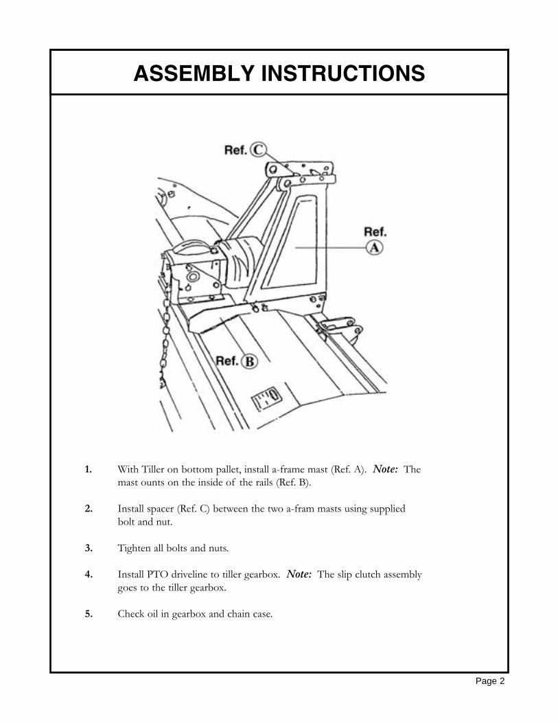
1. With Tiller on bottom pallet, install a-frame mast (Ref. A). Note: The mast ounts on the inside of the rails (Ref. B).
2. Install spacer (Ref. C) between the two a-fram masts using supplied bolt and nut.
3. Tighten all bolts and nuts.
4. Install PTO driveline to tiller gearbox. Note: The slip clutch assemblygoes to the tiller gearbox.
5. Check oil in gearbox and chain case.
Page 2
ASSEMBLY INSTRUCTIONS
CONNECTION TO TRACTOR
Page 3
Your Gearmore Rotary Tiller can be attached to tractors having a Category “I” or Category “II”,3-point hitch.
1. Attach the lower link arms of the tractor to the lower attaching brackets of the tillerby inserting the pins.
2. Attach the top link of the 3-point hitch to the tiller. Next, tighten the lower link arm check chains to prevent any horizontal movement of the tiller, which could cause damage during operation. Adjust the unit so the drive shaft is parallel to the ground in the working position. Adjust the tractor lift linkage or the hydraulic lever lifting stops to prevent the tiller being lifted more than 6” from the ground. This will avoid any damage to the universal joints.
3. Attach the drive shaft, first to the tiller input shaft and then to the PTO of the tractor.Make sure the yokes are locked on to the tractor and tiller shaft.
SLIP CLUTCH DRIVE SHAFT:This tiller has a drive shaft with a slip clutch, which has been calibrated for a certain overload. Toadjust the clutch, tighten or loosen bolts equally. Don’t over-tighten or clutch will lock and not slipunder stress, which could cause damage during operation. The clutch assembly should get warm undernormal operation. If the clutch gets extremely hot, this is a sign of slippage. If the machine sits for anextended period of time with no usage, the bolts should be loosened and the PTO engaged. This willallow the clutch discs to become free again. After a few seconds, shut-off the tractor and retightenbolts equally. Recheck clutch assembly for temperature after using in tilling application. If it is too hot,the bolts need tightening. If it is too cool, loosen bolts.
SET SIDE SKIDS FOR WORKING DEPTH:To regulate working depth, loosen the nuts of the skids and adjust them to the desired position. Setskids equally on both sides.
TRANSMISSION CHAIN TENSION:Your Gearmore Rotary Tiller has an automatic chain tensioner, so no adjustment is necessary.
TINES:When the complete set of tines has to be replaced, it is advisable to replace one at a time to insurethat the new tines are mounted in the same position as the old ones. It is important to fit the boltswith the heads to the side of the tine and the nuts and washers to the side of the flange. It is also recommended to replace all washers with new ones at the time of tine replacement.
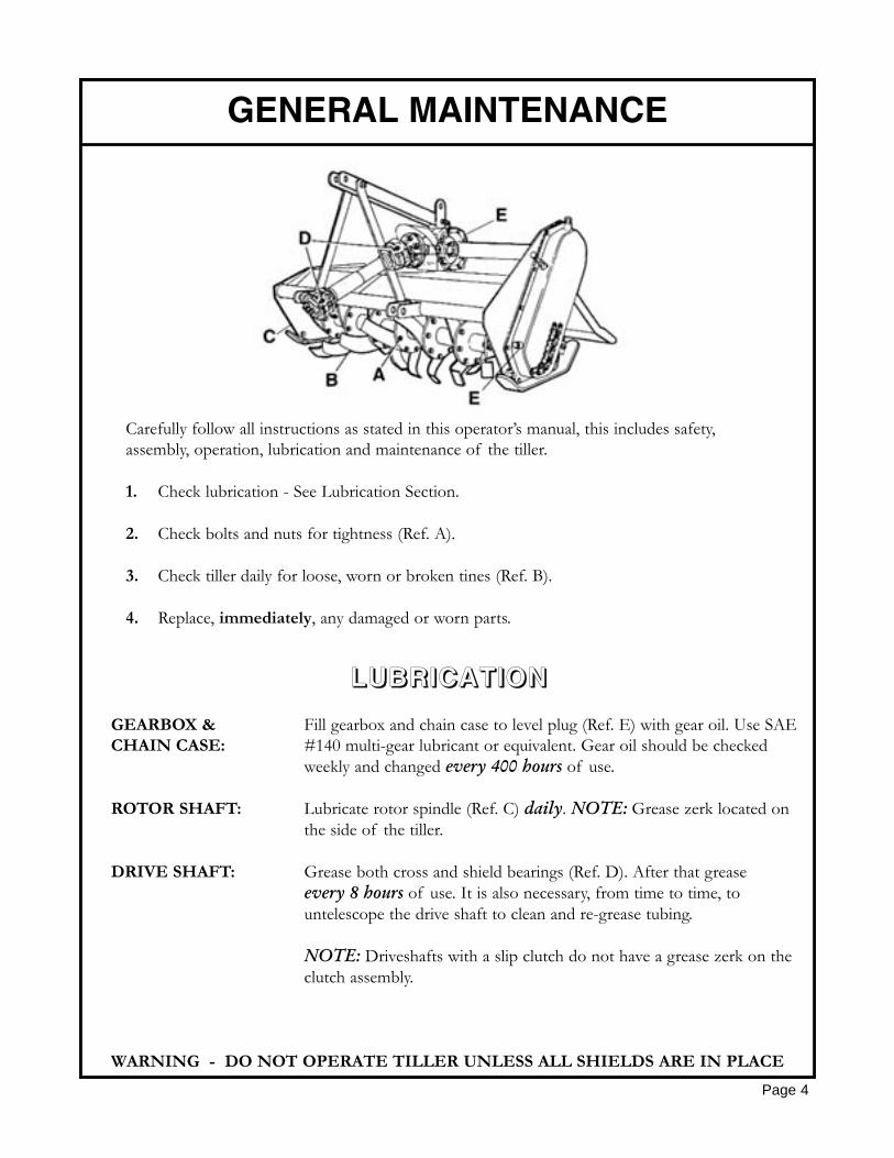
Carefully follow all instructions as stated in this operator’s manual, this includes safety,assembly, operation, lubrication and maintenance of the tiller.
1. Check lubrication - See Lubrication Section.
2. Check bolts and nuts for tightness (Ref. A).
3. Check tiller daily for loose, worn or broken tines (Ref. B).
4. Replace, immediately, any damaged or worn parts.
GEARBOX & Fill gearbox and chain case to level plug (Ref. E) with gear oil. Use SAECHAIN CASE: #140 multi-gear lubricant or equivalent. Gear oil should be checked
weekly and changed every 400 hours of use.
ROTOR SHAFT: Lubricate rotor spindle (Ref. C) daily. NOTE: Grease zerk located on the side of the tiller.
DRIVE SHAFT: Grease both cross and shield bearings (Ref. D). After that grease every 8 hours of use. It is also necessary, from time to time, to untelescope the drive shaft to clean and re-grease tubing.
NOTE: Driveshafts with a slip clutch do not have a grease zerk on the clutch assembly.
WARNING - DO NOT OPERATE TILLER UNLESS ALL SHIELDS ARE IN PLACE
GENERAL MAINTENANCE
Page 4
LLUUBBRRIICCAATTIIOONN
Guards and safety shields are for your protection. DO NOT operate equipment unless they are in place.
Always operate tractor PTO (power take-off) at recommended RPM (revolutions per minute).
Disengage tractor PTO and shift into neutral before attempting to start engine.
Read and observe all safety decals on the tractor and tiller.
NEVER allow anyone within 25’ of machine while it is in operation.
Do not stop or start suddenly when going uphill or downhill. Avoid operation on steep slopes.
Be alert for holes in terrain and other hidden hazards. Always drive slowly over rough ground.
Reduce speed on slopes and in sharp turns to prevent tipping or loss of control. Be careful when changing direction on slopes.
Stop tiller and tractor immediately upon striking an obstruction. Turn off engine, inspect tiller,and repair any damage before resuming operation.
Disengage power to tiller and stop engine before dismounting from tractor, before making any repairs or adjustments, transporting, or unclogging tiller.
Take all possible precautions when leaving tractor unattended: Disengage PTO, lower tiller, shift into neutral, set parking brake, stop engine and remove key from ignition.
Front tractor weights or front tire ballast should be used to enhance front end stability on small tractors.
Check to make sure PTO is properly connected and that the driveline is correct to prevent bottoming out or pulling apart during the full lift range of the hitch.
Never work under tiller without safety blocks.
This implement is designed for a one-man operation. It is the responsibility of the tractor operator to see that no one is in the proximity of the implement when it is started. DO NOT operate the implement with another person within 25’ of the implement or PTO drive.
SAFETY INFORMATION
Page 5
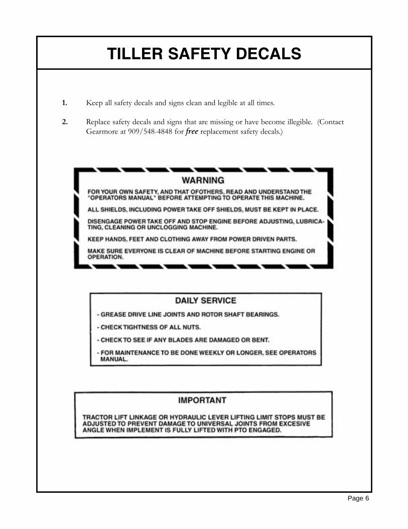
1. Keep all safety decals and signs clean and legible at all times.
2. Replace safety decals and signs that are missing or have become illegible. (Contact Gearmore at 909/548-4848 for free replacement safety decals.)
TILLER SAFETY DECALS
Page 6

TILLER SAFETY DECALS
Page 7
DANGER: Hands and feet couldbe severely injured. Keep away fromrotating parts.
DANGER: Do not stay behind themachine as it could roll over you.
DANGER: Never get near to thePTO shaft while it is in opertion.ACCIDENTAL CONTACTCOULD CAUSE DEATH.
Stop both the machine and the tractorbefore performing any service.

TILLER SAFETY DECALS
Page 8
Please carefully read and understand theoperating instructions before using themachine.
DANGER: The machine could throwheavy or sharp objects. Keep at a safe dis-tance from the machine.

TROUBLESHOOTING CHART
Page 9
PROBLEM CAUSE SOLUTIONDrive shaft damaged Replace worn drive shaft
Tines broken off Replace damaged tines
Bent rotor shaft Replace rotor shaft
PTO Clutch slipping Check slip clutch adjustment
Replace clutch discs
Tractor lower lift arm outof adjustment
Adjust lift arm
Tiller depth skid notproperly adjusted
Adjust skids to level depth
Trying to go too deep onfirst pass
Raise tiller so tilling 3"deep
Tractor in too high a gear Tiller runs smoother in firstor second gear
Tires set out too wide Set in tractor tires
Tractor too large Offset tiller to cover righttire tracks
Improper lubrication Separate and grease bothhalves
PTO twisted Replace twisted parts
Shields damaged Replace shields
Leaving tire tracks
PTO will not untelescope
Excessive vibration
Rotor shaft doesnot turn
Tilling deeper on one side
Tiller bouncing
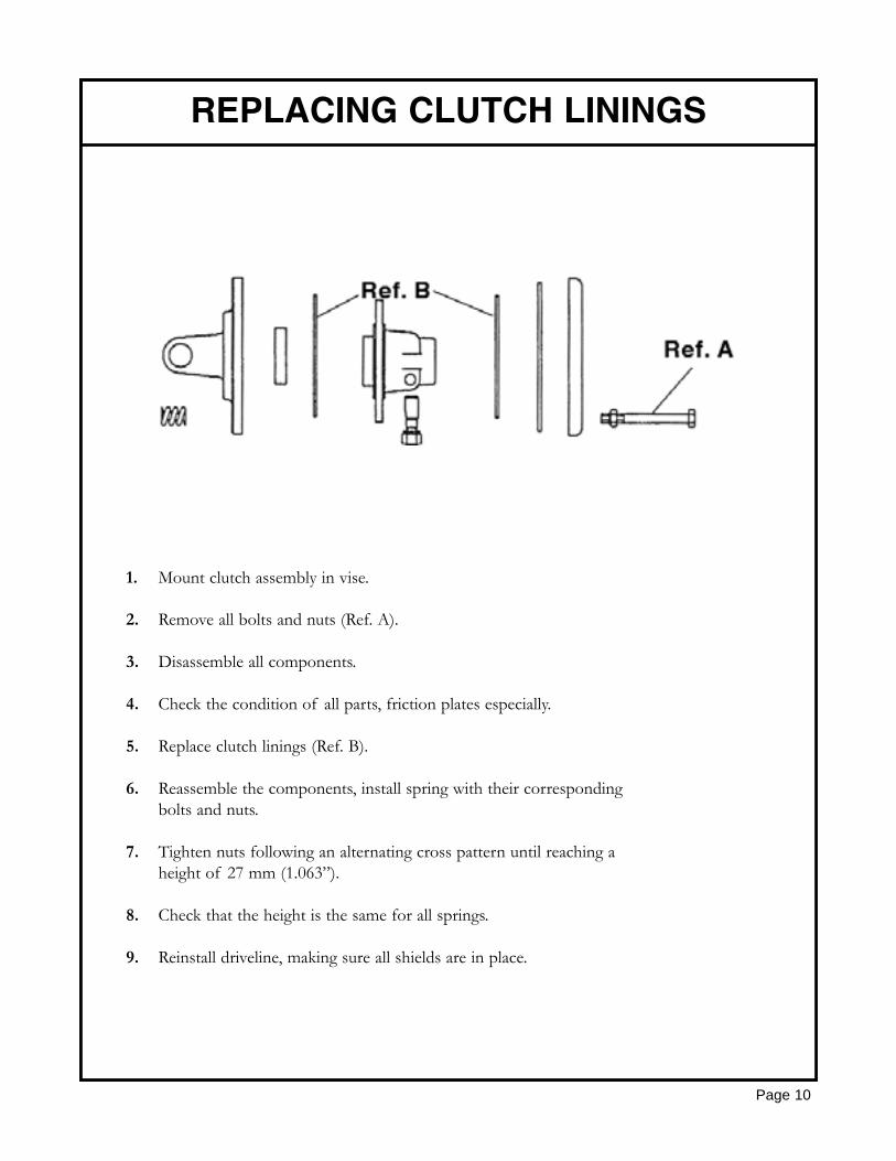
1. Mount clutch assembly in vise.
2. Remove all bolts and nuts (Ref. A).
3. Disassemble all components.
4. Check the condition of all parts, friction plates especially.
5. Replace clutch linings (Ref. B).
6. Reassemble the components, install spring with their corresponding bolts and nuts.
7. Tighten nuts following an alternating cross pattern until reaching a height of 27 mm (1.063”).
8. Check that the height is the same for all springs.
9. Reinstall driveline, making sure all shields are in place.
REPLACING CLUTCH LININGS
Page 10
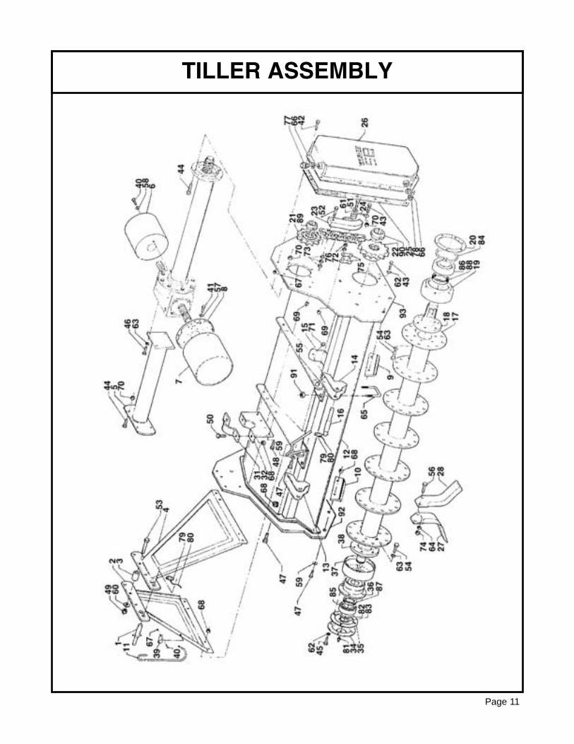
TILLER ASSEMBLY
Page 11
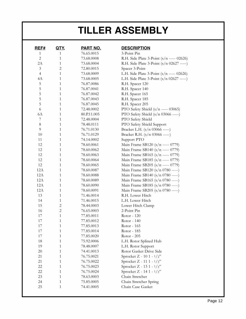
REF# QTY. PART NO. DESCRIPTION1 1 76.65.0015 3-Point Pin2 1 73.68.0008 R.H. Side Plate 3-Point (s/n ----- 02626)
2A 1 73.68.0004 R.H. Side Plate 3-Point (s/n 02627 -----)3 2 72.80.0015 Spacer 3-Point4 1 73.68.0009 L.H. Side Plate 3-Point (s/n ----- 02626)
4A 1 73.68.0005 L.H. Side Plate 3-Point (s/n 02627 -----)5 1 76.87.0086 R.H. Spacer 1205 1 76.87.0041 R.H. Spacer 1405 1 76.87.0042 R.H. Spacer 1655 1 76.87.0043 R.H. Spacer 1855 1 76.87.0045 R.H. Spacer 2056 1 72.48.0002 PTO Safety Shield (s/n ----- 03065)
6A 1 80.P.11.005 PTO Safety Shield (s/n 03066 -----)7 1 72.48.0004 PTO Safety Shield8 1 78.48.0111 PTO Safety Shield Support9 1 76.71.0130 Bracket L.H. (s/n 03066 -----)10 1 76.71.0129 Bracket R.H. (s/n 03066 -----)11 1 74.14.0002 Support PTO12 1 78.60.0061 Main Frame SB120 (s/n ----- 0779)12 1 78.60.0062 Main Frame SB140 (s/n ----- 0779)12 1 78.60.0063 Main Frame SB165 (s/n ----- 0779)12 1 78.60.0064 Main Frame SB185 (s/n ----- 0779)12 1 78.60.0065 Main Frame SB205 (s/n ----- 0779)
12A 1 78.60.0087 Main Frame SB120 (s/n 0780 -----)12A 1 78.60.0088 Main Frame SB140 (s/n 0780 -----)12A 1 78.60.0089 Main Frame SB165 (s/n 0780 -----)12A 1 78.60.0090 Main Frame SB185 (s/n 0780 -----)12A 1 78.60.0091 Main Frame SB205 (s/n 0780 -----)13 1 71.46.0014 R.H. Lower Hitch14 1 71.46.0015 L.H. Lower Hitch15 2 78.44.0003 Lower Hitch Clamp16 2 76.65.0003 2-Point Pin17 1 77.85.0011 Rotor - 12017 1 77.85.0012 Rotor - 14017 1 77.85.0013 Rotor - 16517 1 77.85.0014 Rotor - 18517 1 77.85.0020 Rotor - 20518 1 75.92.0006 L.H. Rotor Splined Hub19 1 78.48.0007 L.H. Rotor Support20 1 74.41.0013 Rotor Gasket Drive Side21 1 76.75.0021 Sprocket Z - 10 1 - 1/2”21 1 76.75.0022 Sprocket Z - 11 1 - 1/2”22 1 76.75.0023 Sprocket Z - 13 1 - 1/2”22 1 76.75.0024 Sprocket Z - 14 1 - 1/2”23 1 78.63.0003 Chain Stretcher24 1 75.85.0005 Chain Stretcher Spring25 1 74.41.0005 Chain Case Gasket
TILLER ASSEMBLY
Page 12
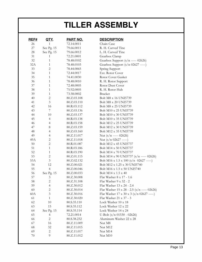
REF# QTY. PART NO. DESCRIPTION26 1 72.14.0011 Chain Case27 See Pg. 15 79.66.0011 R. H. Curved Tine28 See Pg. 15 79.66.0012 L. H. Curved Tine31 1 72.21.0001 Gearbox Clamp32 1 78.48.0102 Gearbox Support (s/n ----- 02626)
32A 1 78.48.0103 Gearbox Support (s/n 02627 -----)33 2 78.44.0065 Spring Support34 1 72.44.0017 Ext. Rotor Cover35 1 74.41.0030 Rotor Cover Gasket36 1 78.48.0010 R. H. Rotor Support37 1 72.48.0005 Rotor Dust Cover38 1 75.92.0005 R. H. Rotor Hub39 1 73.58.0002 Bracket40 2 80.Z.03.108 Bolt M8 x 16 UNI573941 3 80.Z.03.110 Bolt M8 x 20 UNI573942 16 80.R.03.112 Bolt M8 x 25 UNI573943 7 80.Z.03.136 Bolt M10 x 25 UNI573944 10 80.Z.03.137 Bolt M10 x 30 UNI573945 4 80.R.03.138 Bolt M10 x 35 UNI573946 4 80.R.03.158 Bolt M12 x 25 UNI573947 8 80.Z.03.159 Bolt M12 x 30 UNI573948 4 80.Z.03.160 Bolt M12 x 35 UNI573949 4 80.Z.11.017 Nut (s/n ----- 02626)
49A 2 80.Z.11.018 Nut (s/n 02627 -----)50 2 80.R.01.087 Bolt M12 x 45 UNI573751 1 80.R.03.186 Bolt M14 x 50 UNI573752 1 80.R.03.190 Bolt M14 x 70 UNI573753 2 80.Z.01.115 Bolt M14 x 90 UNI5737 (s/n ----- 02626)
53A 3 80.Z.02.132 Bolt M16 x 1.5 x 100 (s/n 02627 -----)54 12 80.Z.00.021 Bolt M12 x 1.25 x 30 UNI574055 4 80.Z.00.046 Bolt M16 x 1.5 x 50 UNI574056 See Pg. 15 80.Z.00.033 Bolt M14 x 1.5 x 4057 3 80.Z.30.008 Flat Washer 8 x 17 - 1.658 2 80.Z.31.108 Flat Washer 9 x 32 - 259 4 80.Z.30.012 Flat Washer 13 x 24 - 2.460 2 80.Z.30.014 Flat Washer 15 x 28 - 2.5 (s/n ----- 02626)
60A 3 80.Z.30.016 Flat Washer 17 x 30 x 3 (s/n 02627 -----)61 1 80.Z.30.020 Flat Washer 21 x 37 - 362 10 80.S.35.110 Lock Washer 10 x 1863 15 80.S.35.112 Lock Washer 12 x 2264 See Pg. 15 80.S.35.114 Lock Washer 14 x 2465 4 72.21.0014 U-Bolt (s/n 01530 - 02626)66 2 80.S.38.232 Aluminum Washer 22 x 2867 16 80.Z.11.009 Nut M868 32 80.Z.11.015 Nut M1269 2 80.Z.11.017 Nut M1470 9 80.Z.11.012 Nut M10
TILLER ASSEMBLY
Page 13

REF# QTY. PART NO. DESCRIPTION
71 4 80.Z.11.018 Nut M16 x 1.572 2 80.S.01.011 Nut M14 UNI558873 3 80.S.02.011 Nut M14 UNI558974 See Pg. 15 80.Z.08.111 Nut M14 x 1.8 UNI558775 1 80.Z.31.930 Chain Link ASA 120 H76 1 80.A.31.325 Chain ASA - 120 H36 Links77 1 80.F.90.116 Breather Plug 1/2”78 1 80.F.90.553 Outlet Plug 1/2”79 3 80.S.77.015 Locking Pin 10 x 3780 3 80.P.05.001 Spring81 1 80.Z.61.010 Grease Nipple M8 x 1.2582 1 80.S.48.446 Spacer83 1 80.S.70.040 Snap Ring E4084 1 80.S.71.110 Snap Ring I11085 1 6308 Bearing 6308 40 x 90 x 2386 1 6310 Bearing 6310 50 x 110 x 2787 1 50X65X8 Oil Seal88 1 65X85X10 Oil Seal89 1 80.Z.56.013 Self Locking Nut M40 x 1.590 1 80.Z.55.014 Self Locking Nut M45 x 1.591 8 80.Z.11.017 Nut M14 (s/n 01530 - 02626092 1 73.68.0046 Side Plate (s/n 0780 - 03434)
92A 1 73.68.0039 Side Plate (s/n 03435 - -----)93 1 73.68.0045 Side Plate L.H. (s/n 0780 - 03434)
93A 1 73.68.0038 Side Plate L.H. (s/n 03435 - -----)
TILLER ASSEMBLY
Page 14
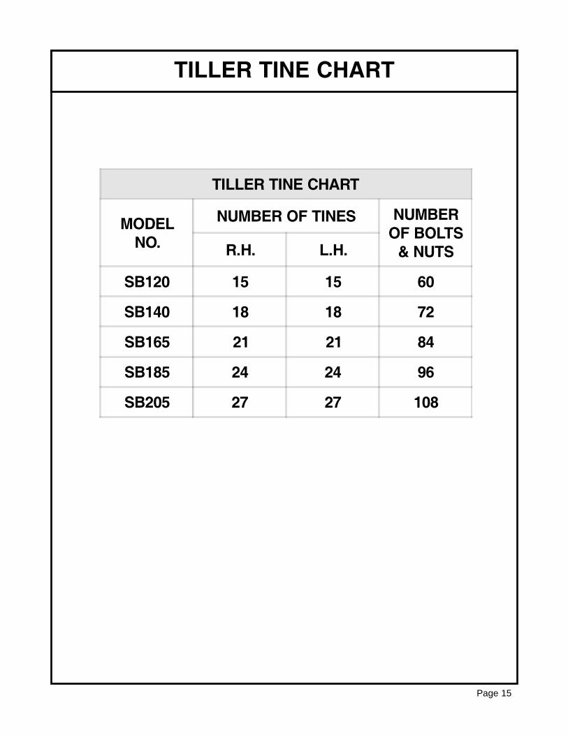
TILLER TINE CHART
Page 15
TILLER TINE CHART
MODELNO.
NUMBER OF TINES NUMBEROF BOLTS
& NUTSR.H. L.H.
SB120 15 15 60
SB140 18 18 72
SB165 21 21 84
SB185 24 24 96
SB205 27 27 108
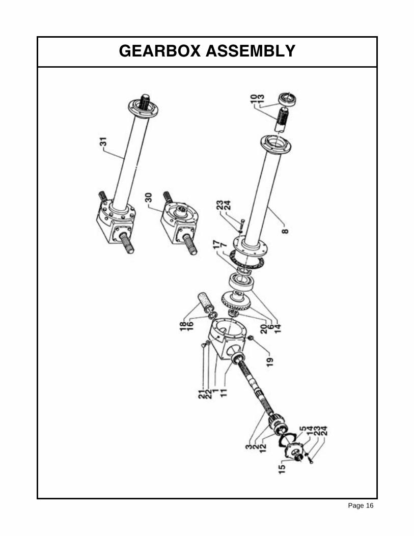
GEARBOX ASSEMBLY
Page 16
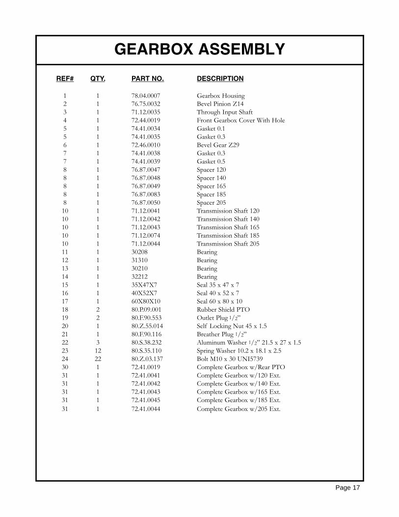
REF# QTY. PART NO. DESCRIPTION
1 1 78.04.0007 Gearbox Housing2 1 76.75.0032 Bevel Pinion Z143 1 71.12.0035 Through Input Shaft4 1 72.44.0019 Front Gearbox Cover With Hole5 1 74.41.0034 Gasket 0.15 1 74.41.0035 Gasket 0.36 1 72.46.0010 Bevel Gear Z297 1 74.41.0038 Gasket 0.37 1 74.41.0039 Gasket 0.58 1 76.87.0047 Spacer 1208 1 76.87.0048 Spacer 1408 1 76.87.0049 Spacer 1658 1 76.87.0083 Spacer 1858 1 76.87.0050 Spacer 20510 1 71.12.0041 Transmission Shaft 12010 1 71.12.0042 Transmission Shaft 14010 1 71.12.0043 Transmission Shaft 16510 1 71.12.0074 Transmission Shaft 18510 1 71.12.0044 Transmission Shaft 20511 1 30208 Bearing12 1 31310 Bearing13 1 30210 Bearing14 1 32212 Bearing15 1 35X47X7 Seal 35 x 47 x 716 1 40X52X7 Seal 40 x 52 x 717 1 60X80X10 Seal 60 x 80 x 1018 2 80.P.09.001 Rubber Shield PTO19 2 80.F.90.553 Outlet Plug 1/2”20 1 80.Z.55.014 Self Locking Nut 45 x 1.521 1 80.F.90.116 Breather Plug 1/2”22 3 80.S.38.232 Aluminum Washer 1/2” 21.5 x 27 x 1.523 12 80.S.35.110 Spring Washer 10.2 x 18.1 x 2.524 22 80.Z.03.137 Bolt M10 x 30 UNI573930 1 72.41.0019 Complete Gearbox w/Rear PTO31 1 72.41.0041 Complete Gearbox w/120 Ext.31 1 72.41.0042 Complete Gearbox w/140 Ext.31 1 72.41.0043 Complete Gearbox w/165 Ext.31 1 72.41.0045 Complete Gearbox w/185 Ext.31 1 72.41.0044 Complete Gearbox w/205 Ext.
GEARBOX ASSEMBLY
Page 17
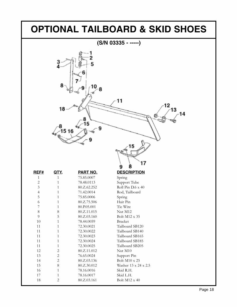
REF# QTY. PART NO. DESCRIPTION1 1 75.85.0007 Spring2 1 78.48.0113 Support Tube3 1 80.Z.62.252 Roll Pin D.6 x 404 1 71.42.0014 Rod, Tailboard5 1 75.85.0006 Spring6 1 80.Z.75.506 Hair Pin7 1 80.P.05.001 Tie Wire8 8 80.Z.11.015 Nut M129 5 80.Z.03.160 Bolt M12 x 3510 1 78.44.0059 Bracket11 1 72.30.0021 Tailboard SB12011 1 72.30.0022 Tailboard SB14011 1 72.30.0023 Tailboard SB16511 1 72.30.0024 Tailboard SB18511 1 72.30.0025 Tailboard SB20512 2 80.Z.11.012 Nut M1013 2 76.65.0024 Support Pin14 2 80.Z.03.136 Bolt M10 x 2515 8 80.Z.30.012 Washer 13 x 24 x 2.516 1 78.16.0016 Skid R.H.17 1 78.16.0017 Skid L.H.18 2 80.Z.03.161 Bolt M12 x 40
OPTIONAL TAILBOARD & SKID SHOES
Page 18
(S/N 03335 - -----)
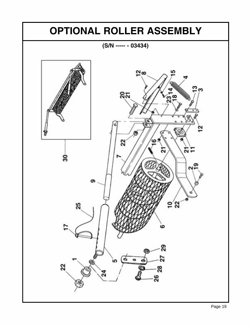
OPTIONAL ROLLER ASSEMBLY
Page 19
(S/N ----- - 03434)
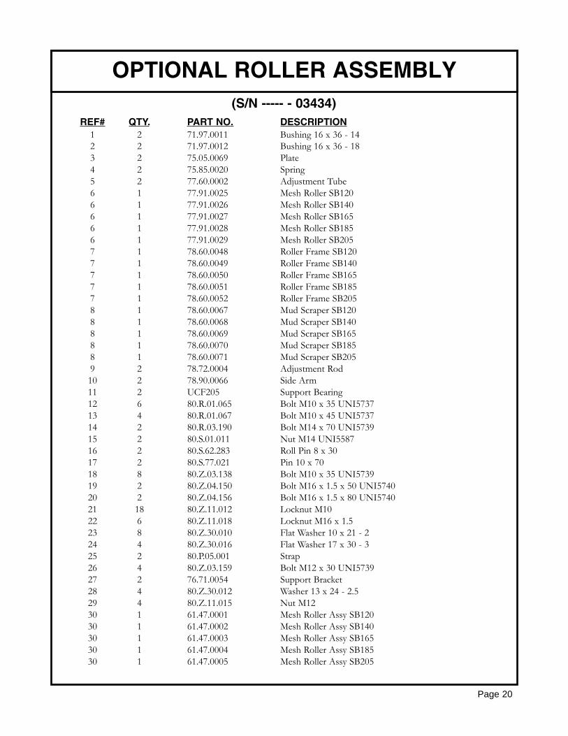
REF# QTY. PART NO. DESCRIPTION1 2 71.97.0011 Bushing 16 x 36 - 142 2 71.97.0012 Bushing 16 x 36 - 183 2 75.05.0069 Plate4 2 75.85.0020 Spring5 2 77.60.0002 Adjustment Tube6 1 77.91.0025 Mesh Roller SB1206 1 77.91.0026 Mesh Roller SB1406 1 77.91.0027 Mesh Roller SB1656 1 77.91.0028 Mesh Roller SB1856 1 77.91.0029 Mesh Roller SB2057 1 78.60.0048 Roller Frame SB1207 1 78.60.0049 Roller Frame SB1407 1 78.60.0050 Roller Frame SB1657 1 78.60.0051 Roller Frame SB1857 1 78.60.0052 Roller Frame SB2058 1 78.60.0067 Mud Scraper SB1208 1 78.60.0068 Mud Scraper SB1408 1 78.60.0069 Mud Scraper SB1658 1 78.60.0070 Mud Scraper SB1858 1 78.60.0071 Mud Scraper SB2059 2 78.72.0004 Adjustment Rod10 2 78.90.0066 Side Arm11 2 UCF205 Support Bearing12 6 80.R.01.065 Bolt M10 x 35 UNI573713 4 80.R.01.067 Bolt M10 x 45 UNI573714 2 80.R.03.190 Bolt M14 x 70 UNI573915 2 80.S.01.011 Nut M14 UNI558716 2 80.S.62.283 Roll Pin 8 x 3017 2 80.S.77.021 Pin 10 x 7018 8 80.Z.03.138 Bolt M10 x 35 UNI573919 2 80.Z.04.150 Bolt M16 x 1.5 x 50 UNI574020 2 80.Z.04.156 Bolt M16 x 1.5 x 80 UNI574021 18 80.Z.11.012 Locknut M1022 6 80.Z.11.018 Locknut M16 x 1.523 8 80.Z.30.010 Flat Washer 10 x 21 - 224 4 80.Z.30.016 Flat Washer 17 x 30 - 325 2 80.P.05.001 Strap26 4 80.Z.03.159 Bolt M12 x 30 UNI573927 2 76.71.0054 Support Bracket28 4 80.Z.30.012 Washer 13 x 24 - 2.529 4 80.Z.11.015 Nut M1230 1 61.47.0001 Mesh Roller Assy SB12030 1 61.47.0002 Mesh Roller Assy SB14030 1 61.47.0003 Mesh Roller Assy SB16530 1 61.47.0004 Mesh Roller Assy SB18530 1 61.47.0005 Mesh Roller Assy SB205
OPTIONAL ROLLER ASSEMBLY
Page 20
(S/N ----- - 03434)
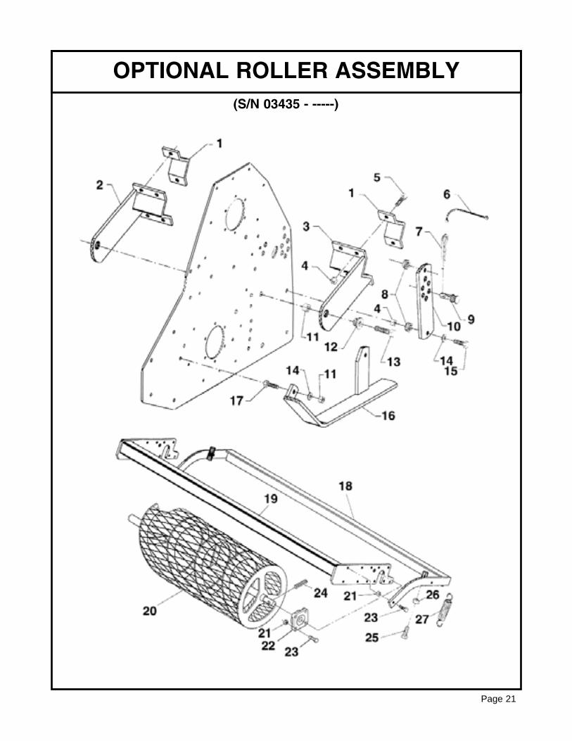
OPTIONAL ROLLER ASSEMBLY
Page 21
(S/N 03435 - -----)

REF# QTY. PART NO. DESCRIPTION
1 4 78.44.0001 1/2 Clamp2 1 78.90.0075 Bracket, Support R.H.3 1 78.90.0076 Bracket, Support L.H.4 14 80.Z.11.015 Nut M125 8 80.Z.03.161 Bolt M12 x 406 2 80.P.05.001 Tie Wire7 2 80.Z.75.505 Hair Pin8 4 72.80.0046 Bushing9 2 76.65.0057 Pin10 2 76.71.0149 Bracket, Adjustment11 2 80.Z.11.018 Nut M1612 2 71.97.0012 Spacer 16.5 x 36 x 1813 2 80.Z.00.044 Bolt M16 x 1.5 x 4514 6 80.Z.30.012 Washer 13 x 24 x 2.515 4 80.Z.01.087 Bolt m12 x 4516 1 78.16.0021 Skid L.H.17 2 80.Z.03.160 Bolt M12 x 3518 1 78.60.0179 Scraper SB12018 1 78.60.0181 Scraper SB14018 1 78.60.0182 Scraper SB16518 1 78.60.0183 Scraper SB18518 1 78.60.0184 Scraper SB20519 1 78.60.0171 Bracket Support SB12019 1 78.60.0173 Bracket Support SB14019 1 78.60.0174 Bracket Support SB16519 1 78.60.0175 Bracket Support SB18519 1 78.60.0176 Bracket Support SB20520 1 77.91.0042 Roller SB12020 1 77.91.0026 Roller SB14020 1 77.91.0027 Roller SB16520 1 77.91.0028 Roller SB18520 1 77.91.0029 Roller SB20521 10 80.Z.11.012 Nut22 2 UCF205 Bearing23 10 80.R.01.065 Bolt M10 x 3524 2 80.S.62.283 Roll Pin 8 x 3025 2 80.R.03.190 Bolt M14 x 7026 2 80.Z.08.011 Nut M1427 2 75.85.0020 Spring
OPTIONAL ROLLER ASSEMBLY
Page 22
(S/N 03435 - -----)
REF# QTY. PART NO. DESCRIPTION
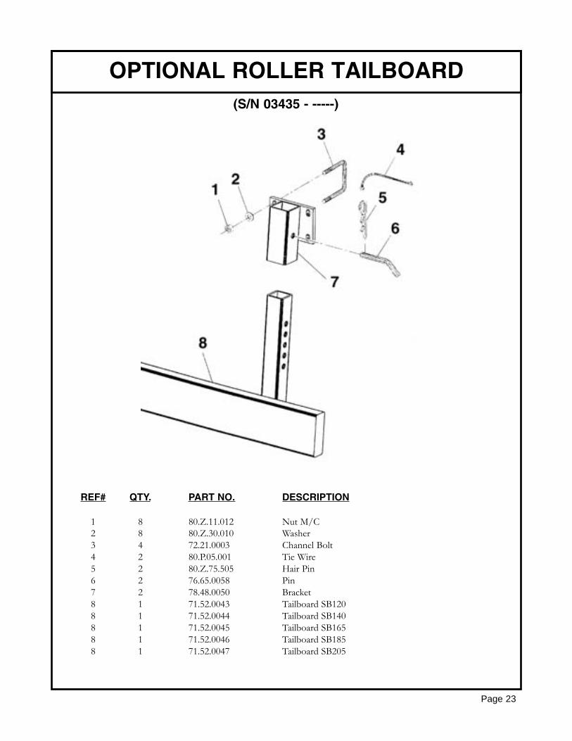
1 8 80.Z.11.012 Nut M/C2 8 80.Z.30.010 Washer3 4 72.21.0003 Channel Bolt4 2 80.P.05.001 Tie Wire5 2 80.Z.75.505 Hair Pin6 2 76.65.0058 Pin7 2 78.48.0050 Bracket8 1 71.52.0043 Tailboard SB1208 1 71.52.0044 Tailboard SB1408 1 71.52.0045 Tailboard SB1658 1 71.52.0046 Tailboard SB1858 1 71.52.0047 Tailboard SB205
OPTIONAL ROLLER TAILBOARD
Page 23
(S/N 03435 - -----)
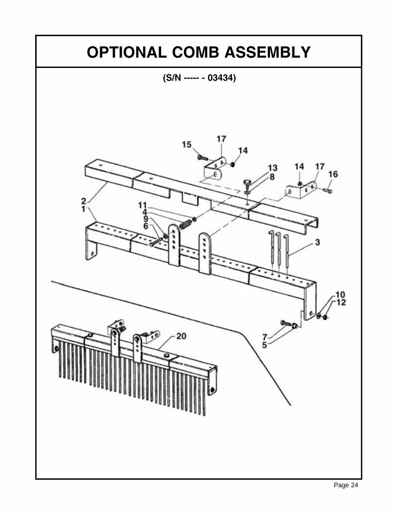
OPTIONAL COMB ASSEMBLY
Page 24
(S/N ----- - 03434)
REF# QTY. PART NO. DESCRIPTION
1 1 78.60.0036 Comb Frame SB1201 1 78.60.0037 Comb Frame SB1401 1 78.60.0038 Comb Frame SB1651 1 78.60.0039 Comb Frame SB1851 1 78.60.0040 Comb Frame SB2052 1 72.44.0038 Comb Cover SB1202 1 72.44.0039 Comb Cover SB1402 1 72.44.0040 Comb Cover SB1652 1 72.44.0041 Comb Cover SB1852 1 72.44.0042 Comb Cover SB2053 As Req’d 78.75.0001 Comb Rod, 12, 38, 45, 53, 60, 694 2 75.85.0007 Shock Absorber Tailboard Spring5 2 71.97.0012 Bushing D16.5 x 36 - 186 2 80.Z.01.118 Bolt M14 x 110 UNI57377 2 80.Z.04.149 Bolt M16 x 4.5 x 15 UNI57408 2 80.Z.30.010 Flat Washer 10 x 21 - 29 2 80.Z.30.014 Flat Washer 15 x 28 - 2.510 2 80.Z.30.016 Flat Washer 17 x 30 - 311 2 80.Z.11.017 Nut M1412 2 80.Z.11.018 Nut M16 x 1.513 2 80.P.28.061 Knob M10 x 3514 4 80.Z.11.015 Nut M1215 2 80.Z.03.160 Bolt M12 x 3516 2 80.Z.03.161 Bolt M12 x 4017 2 78.44.0065 Comb Support20 1 72.42.0002 Complete Comb SB12020 1 72.42.0003 Complete Comb SB14020 1 72.42.0004 Complete Comb SB16520 1 72.42.0005 Complete Comb SB18520 1 72.42.0006 Complete Comb SB205
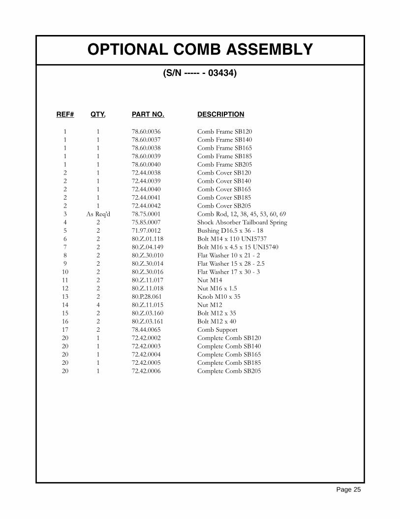
OPTIONAL COMB ASSEMBLY
Page 25
(S/N ----- - 03434)
REF# QTY. PART NO. DESCRIPTION
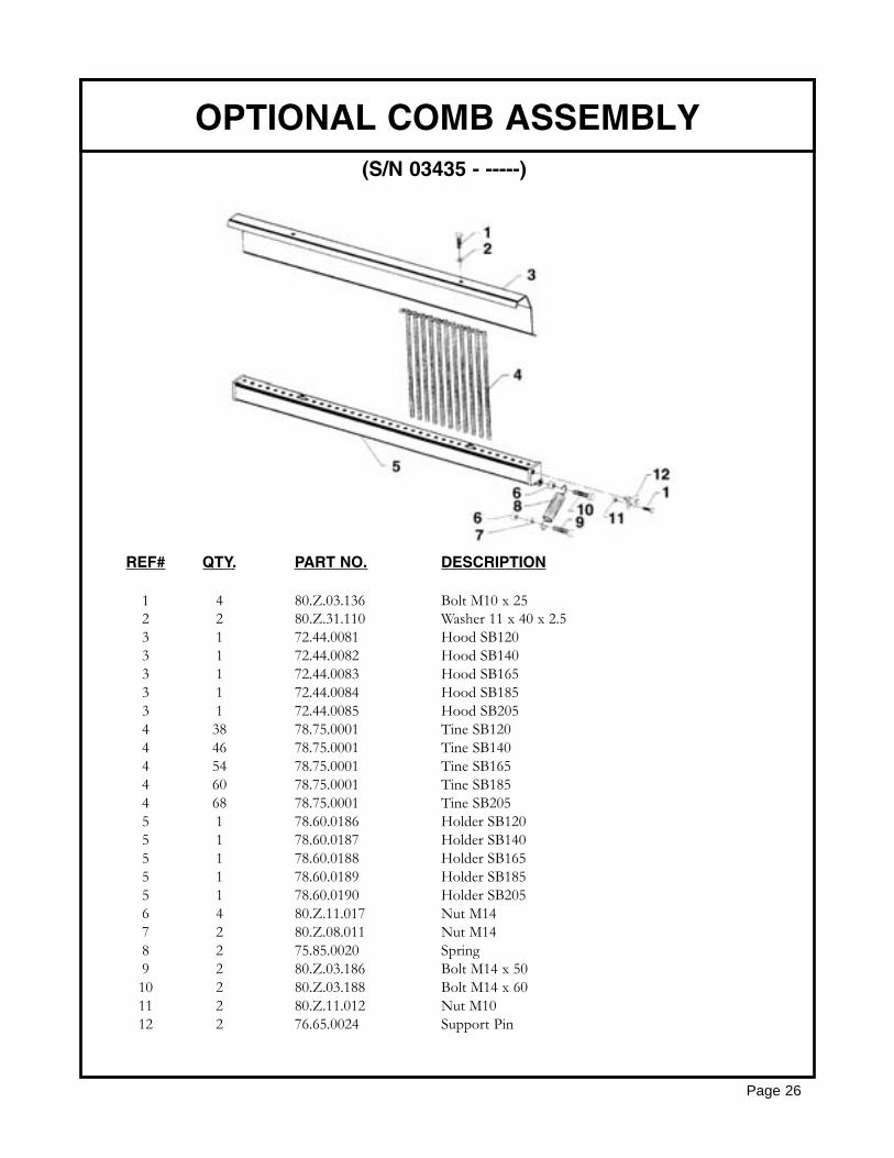
1 4 80.Z.03.136 Bolt M10 x 252 2 80.Z.31.110 Washer 11 x 40 x 2.53 1 72.44.0081 Hood SB1203 1 72.44.0082 Hood SB1403 1 72.44.0083 Hood SB1653 1 72.44.0084 Hood SB1853 1 72.44.0085 Hood SB2054 38 78.75.0001 Tine SB1204 46 78.75.0001 Tine SB1404 54 78.75.0001 Tine SB1654 60 78.75.0001 Tine SB1854 68 78.75.0001 Tine SB2055 1 78.60.0186 Holder SB1205 1 78.60.0187 Holder SB1405 1 78.60.0188 Holder SB1655 1 78.60.0189 Holder SB1855 1 78.60.0190 Holder SB2056 4 80.Z.11.017 Nut M147 2 80.Z.08.011 Nut M148 2 75.85.0020 Spring9 2 80.Z.03.186 Bolt M14 x 5010 2 80.Z.03.188 Bolt M14 x 6011 2 80.Z.11.012 Nut M1012 2 76.65.0024 Support Pin
OPTIONAL COMB ASSEMBLY
Page 26
(S/N 03435 - -----)
REF# QTY. PART NO. DESCRIPTION
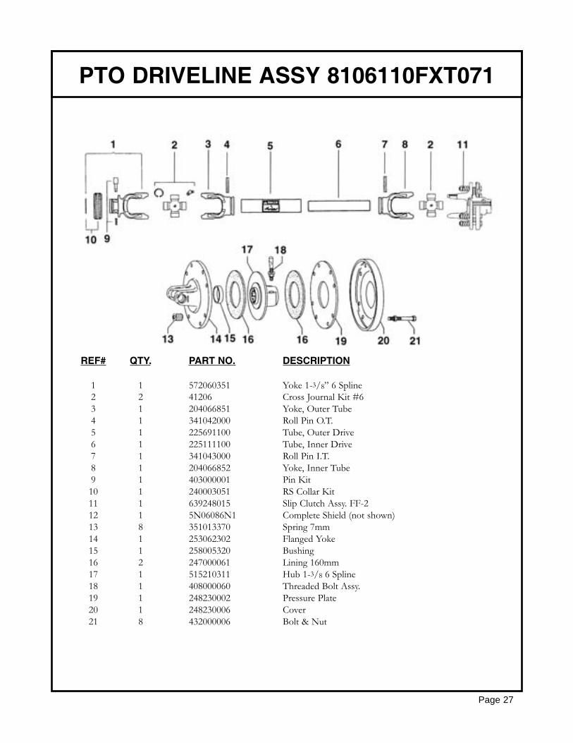
1 1 572060351 Yoke 1-3/8” 6 Spline2 2 41206 Cross Journal Kit #63 1 204066851 Yoke, Outer Tube4 1 341042000 Roll Pin O.T.5 1 225691100 Tube, Outer Drive6 1 225111100 Tube, Inner Drive7 1 341043000 Roll Pin I.T.8 1 204066852 Yoke, Inner Tube9 1 403000001 Pin Kit10 1 240003051 RS Collar Kit11 1 639248015 Slip Clutch Assy. FF-212 1 5N06086N1 Complete Shield (not shown)13 8 351013370 Spring 7mm14 1 253062302 Flanged Yoke15 1 258005320 Bushing16 2 247000061 Lining 160mm17 1 515210311 Hub 1-3/8 6 Spline18 1 408000060 Threaded Bolt Assy.19 1 248230002 Pressure Plate20 1 248230006 Cover21 8 432000006 Bolt & Nut
PTO DRIVELINE ASSY 8106110FXT071
Page 27
Page 28
GEARMORE, INC., warrants each new Gearmore product to be free from defects in materi-al and workmanship for a period of twelve (12) months from date of purchase to the originalpurchaser. This warranty shall not apply to implements or parts that have been subject tomisuse, negligence, accident, or that have been altered in any way.
Our obligation shall be limited to repairing or replacement of any part, provided that suchpart is returned within thirty (30) days from date of failure to Gearmore through the dealerfrom whom the purchase was made, transportation charges prepaid.
This warranty shall not be interpreted to render us liable for injury or damages of any kind ornature, direct, consequential or contingent, to person or property. This warranty does notextend to loss of crops, loss because of delay in harvesting or any other expenses, for anyother reasons.
Gearmore in no way warranties engines, tires, or other trade accessories, since these itemsare warranted separately by these respective manufacturers.
Gearmore reserves the right to make improvements in design or changes in specification atany time, without incurring any obligations to owners or units previously sold.
GEARMORE, INC.13477 Benson Ave.
Chino, CA 91710Always refer to and heed machine operating warning decals on machine.
LIMITED WARRANTY
The serial number of this product is stored in our computer database, thussubmitting a warranty registration card is not required.