vcd dual head 8 dual head axial inserter - universal ...graphiclib)/374-02.pdf/...gs-374-02...
TRANSCRIPT

6292C/6298CGS-374-02Universal Part Number: GS-374-02Reference Configuration #46927506
Issued 2/00
VCD Dual Head 8Dual Head Axial Inserter
(6292C/6298C)

6292C/6298C GS-374-02

6292C/6298CGS-374-02
Axial Lead Inserter Features
Insertion span capabilities from 5mm (0.197") to 22.43mm (0.883") with standard tape in-put, depending on tooling selected
VME-based control system with embedded P.C.
IM-Universal Platform Software with graphical user interface
Servo motor driven insertion heads, clinches, insertion span axes, and X-T table axes
Uninterruptable Power Supply (UPS) included with each machine
Scrap Tape Removers included with each machine
* Patent Pending
VCD DH 8Dual Head Axial Inserter
Model 6292C Servo Drive*(Shown with Optional Internal Board Handling System)
CE-Compliant
High-performance insertion machine with insertion rates up to 40,000 components perhour with both heads, and insertion PPM of 150 or better
Insertion Machine DivisionProduct Line
Insertion Machine DivisionProduct Line

6292C/6298C GS-374-02

6292C/6298CGS-374-02
VCD DH 8Dual Head Axial Inserter with Loader/Unloader
Model 6298C Servo Drive*(Shown with Loader/Unloader: Magazine-to-Magazine)
CE-Compliant
Board Handling System Configurations
* Patent Pending
Same features as VCD DH 8, Model 6292C, plus...n Internal Board Handling System (BHS)n Auto MisMark and Bad Board Reject Stationn Loader/Unloader: Magazine-to-Magazine, CE-compliant with Long Buffers onlyn Loader/Unloader: Vacuum Bare Board-to-Magazine, not CE-compliantn Loader/Unloader: Destacker on 29", 44", or 58" Conveyor-to-Magazine, CE- compliant with 44" or 58" Conveyor and Long Buffers only
Elevator and Long BufferLoader, with CE-Compliant
Safety Screens
Elevator and LongBuffer Unloader, with
CE-CompliantSafety Screens
Insertion Machine DivisionProduct Line
Insertion Machine DivisionProduct Line

6292C/6298C GS-374-02

6292C/6298CGS-374-02
Contents
Introduction ............................................................................................................... 1Functional Description ............................................................................................. 1Standard Features ..................................................................................................... 2
Control System..................................................................................................... 2Power Input and Distribution ........................................................................... 2Uninterruptable Power Supply (UPS) .............................................................. 3VME Chassis ................................................................................................. 3Input/Output Box ............................................................................................ 3Insertion Span Axis ....................................................................................... 4Clinch Anvil Drive ........................................................................................... 4Push Button Panel ......................................................................................... 4High Power Servo Chassis ............................................................................. 4Head Drive ..................................................................................................... 4Board Error Correction (B.E.C.) ...................................................................... 5
Machine System Software .................................................................................... 6System Setup ................................................................................................ 6Advanced Product Editor (APE) ..................................................................... 6Product Changeover ....................................................................................... 6Production Control .......................................................................................... 6Machine Status .............................................................................................. 7Management Information ................................................................................ 7IM Diagnostics ............................................................................................... 7On-Line Documentation .................................................................................. 7
CAD Data Requirements ....................................................................................... 8CAD File Requirements .................................................................................. 8Sample CAD File Format Notes ................................................................... 10Additional APE Features .............................................................................. 10Off-Line Pattern Programming Specifications ............................................... 11
System Mechanics ............................................................................................. 12X-Y Positioning System ............................................................................... 12Machine Console/Covers ............................................................................. 12Machine Status Light ................................................................................... 13Insertion Head.............................................................................................. 13Insertion Hole Span ..................................................................................... 13Insertion Tooling ........................................................................................... 14Scrap Tape Remover .................................................................................... 15Cut and Clinch.............................................................................................. 15Board Error Correction Alignment Template .................................................. 16Input Components ........................................................................................ 16
Optional Features .................................................................................................... 17Workboard Holders ............................................................................................. 17Automatic Board Handling Configurations ........................................................... 17Network Kit ......................................................................................................... 18Host Computer Interface Kit ............................................................................... 18Remote P.C. Software/Off-Line Programming ..................................................... 18Remote P.C. ....................................................................................................... 18
Supporting Documents ........................................................................................... 19Technical Specifications ........................................................................................ 20
Component Definitions ........................................................................................ 20Insertion Tooling Specification ............................................................................ 21Component Body Length Considerations ............................................................ 22Minimum Insertion Hole Span Formulas for Maximum Body Lengths ................. 22

6292C/6298C GS-374-02
Contents
Recommended Component Clearances .............................................................. 23Insertion Tooling Footprint ................................................................................... 24Board Error Correction Detection Area ................................................................ 27Auto MisMark ..................................................................................................... 27Insertion Rate Determination............................................................................... 28
Insertion Rate .............................................................................................. 28Positioning System ...................................................................................... 28
Insertable Area ................................................................................................... 28Input Specifications ............................................................................................ 28Stand-Alone Installation Considerations .............................................................. 29
Machine Shipping Dimensions ..................................................................... 29VCD DH8, Non-Pass Through: Side View...................................................... 30Service Requirements (including Uninterruptable Power Supply) ................... 31Environmental Requirements........................................................................ 32
Appendix: Automatic Board Handling Systems ................................................. A-33Index ............................................................................................................... A-33Introduction ..................................................................................................... A-34Board Handling Interface Standard .................................................................. A-35Technical Specifications for Internal Board Handling System (BHS) ................ A-36Technical Specifications for Loader/Unloader: Elevator/Buffer Configuration ... A-40
Magazine Elevators .................................................................................. A-40Magazine Input/Output Buffers .................................................................. A-40Magazines ................................................................................................ A-41
Universal Magazine Specifications .................................................................. A-42Technical Specifications for Loader/Unloader: Vacuum Bare Board-to-MagazineConfiguration ................................................................................................... A-45Technical Specifications for Loader/Unloader: Destacker/Conveyor-to-MagazineConfiguration ................................................................................................... A-48Installation Considerations: Loader/Unloader ................................................... A-51Service Requirements ..................................................................................... A-52

6292C/6298CGS-374-02
All specifications are subject to periodic review and may be changed withoutnotice. Illustrations may not be drawn to scale.
© Universal Instruments Corporation, 2000. All rights reserved.
The following are trademarks of Universal Instruments Corporation, registeredU.S. Patent and Trademark Office: UICS, Universal, U-Design.
Ethernet is a trademark of Xerox Corporation. Intel is a trademark of IntelCorporation. OS/2 is a registered trademark of International Business MachinesCorporation.
Indicates a change from the previous edition of this document. Bar alongside textindicates entire section reflects change from the previous edition.

6292C/6298C GS-374-02
Glossary of Acronyms and Specialized Terms
Acronym/Term MeaningAC Alternating Current: type of electrical power generationAPE Advanced Product Editor (Universal brand name)ASCII American National Standard Code for Information InterchangeAWG American Wire Gauge: wire size standardBEC Board Error Correction (Universal brand name)BHS Board Handling System: means of transporting PCBsCAD Computer-Aided DesignCD-ROM Compact Disc-Read Only MemoryCE Conformité Europeanne: European safety standardCFM Cubic Feet per Minute: measurement of air flowCTA Component Transfer AssemblyDC Direct Current: type of electrical power generationERV Expanded Range Component Verifier (Universal brand name)GEM Generic Equipment ModelGS General Specification (Universal brand name)GUI Graphical User InterfaceHSMS High Speed SECS Message Service: implements SECS2 messaging over a
network linkHz Hertz (cycles per second): measurement of electrical frequencyIM Insertion Machine: equipment for through hole component insertionIMC Insertion Machine ComponentsIM-UPS Insertion Machine-Universal Platform Software (Universal brand name): operat-
ing software for Universal Series 8 through hole equipmentI/O Input/OutputIP Index of Protection: resistance of machine to contamination by foreign objectsLED Light Emitting Diode: electrical componentMIT Machine Interface Translator (VME to I/O bus)MMIT Mini Machine Interface Translator (VME to I/O bus)OS/2® Operating System 2 (IBM Corp. brand name)PAC Positive Axis ControlP.C. Personal ComputerPCB (or PC board) Printed Circuit BoardPPM Parts Per Million: measurement of machine performanceSCFM Standard Cubic Feet per Minute: measurement of air flowSECS Semiconductor Equipment Communications Standard: interface between host
computer and assembly machinesSEMI Semiconductor Equipment & Materials InternationalSMC Surface Mount ComponentsSMEMA Surface Mount Equipment Manufacturers AssociationTCP/IP Transfer Control Protocol/Internet Protocol: network communication protocolUCT Universal Control Terminal (Universal brand name): personal computer for
operating IM equipmentUICS Universal Instruments Control Software (Universal brand name)UPS Uninterruptible Power SupplyVA Volt-Amps: measurement of electrical power consumptionVAC Volts Alternating CurrentVCD Variable Center DistanceVDC Volts Direct CurrentVGA Video Graphics Array: type of CRT monitor standardVME® Versa Module Eurocard (Motorola brand name): industry standard for 32-bit
computer bus

Page 1GS-374-02
Introduction
Universal’s high-speed variable center distance dual head axiallead insertion machine, VCD DH 8, features VME-based controlwith an embedded P.C. and IM-Universal Platform Software(IM-UPS), including a graphical user interface.
The product line comes in two models: 6292C, manual load, orwith internal Board Handling System (BHS); and 6298C, with au-tomatic board handling and loaders/unloaders. Dual indexing ro-tary tables, high-speed, servo-driven insertion heads and cut andclinches are also featured.
Models 6292C and 6298C achieve insertion rates up to 40,000components per hour: 20,000 CPH with each head. Insertionrates will vary depending upon PCB size and the number of axialcomponents inserted. (See Insertion Rate Determination in theTechnical Specifications section.)
In consideration of essential health and safety requirements, theVCD DH 8, Models 6298C and 6292C with BHS, are CE-com-pliant. The Vacuum Bare Board-to-Magazine, Destacker on 29"Conveyor-to-Magazine, and stand-alone machine without boardhandling configurations, are not CE-compliant.
Functional Description
Models 6292C and 6298C automatically insert axial leaded com-ponents from dual, sequenced taped input packages into printedcircuit boards (PC boards). A product (pattern program) is cre-ated with information pertaining to the components, PC boards,and processing requirements. When this product is loaded, ma-chine operation can be started.
When the machine is started, the PC boards can be located andclamped into the workboard holders. The product activates theX-Y positioning system and the component feed. The componentfeed transfers taped components to the insertion heads. The in-sertion tooling cuts the component leads from the carrier tape tothe required length determined by the product, and forms thecomponents for insertion.
After insertion through the PC board, the component leads are cutand formed (clinched) to mechanically secure them to the board.The process continues until the product is completed and all requiredaxial components are in place. When the product is complete, thePC board can be removed from the machine.

Page 2 GS-374-02
Standard Features
Control System
The VCD DH 8 employs a control system, including input power/distribution, VME bus, I/O, and servo system. Brief descriptionsof major elements of this control system follow.
Power Input and Distribution
The input power to this machine nominally is 230 VAC, singlephase, 15 amps, 50 or 60 Hz. All components of the machinecan operate over the range of 47-63 Hz without configurationchange. In combination with the supplied Uninterruptable PowerSupply (UPS), the machine will accept a wider range of inputs(see “Service Requirements” section) and provide power to runthe machine briefly in the event of a short power interruption.There are filters to prevent machine generated noise from gettingon the power lines as well as to prevent noise on the power linesfrom interfering with machine operation. The machine has alockable disconnect switch for safety during service.
Internal to the machine, the 230 volts is directly used for amplifierpower for the heads, clinches, and insertion span drives. There isa power conditioner transformer used for creating 120 VAC forthe remainder of the machine functions. This includes the fanpanels, the power chassis, the VME chassis, and the monitor.This transformer will also supply 120 VAC for the attached el-evators and bare board loaders.
The power chassis, in turn, provides DC power for machine op-eration. This includes 56 VDC for Board Handling motors; +5and ±15 VDC for the I/O box; and 12 VDC for general purposeuse (valve solenoids, sensors, indicators, etc.). The 56 VDC isdisconnected from the machine when interlocks are violated.The power chassis also provides 12 VAC for the worklight and24 VAC for the machine status light, the interlock circuits, andthe scrap tape pullers.

Page 3GS-374-02
Uninterruptable Power Supply (UPS)
An Uninterruptable Power Supply is standard with the VCD DH8 and external to the machine, providing continuous power at alltimes. The UPS will seamlessly transition to battery power in theevent of an electric service interruption.
Battery capacity at full charge should allow full machine opera-tion for up to 10 minutes after loss of input power. The machineshould be brought to a controlled stop until electrical service is re-stored.
VME Chassis
The VME chassis is a state-of-the-art, multi-processor rack-mounted controller. It has an embedded Intel®-based P.C. whichis used for the main operator interface. Attached to it are stan-dard VGA monitor, keyboard, and pointing device. The main ma-chine controller is a 680X0-based unit. This board handles all ofthe machine functions and timing. It does not directly handle themotor control, but does direct the motion controllers.
Two, four-axis intelligent motion controllers are used. These are68000-based dedicated processors. The motion controllers pro-vide speed and destination information to the servo amps, whichdrive the motors. Encoders, tachometers, and resolvers providepositional and velocity feedback to the motion controllers for pre-cise position control. Three of these motion controllers are usedwith the Loader/Unloader configuration.
As an interface between the VME controller and the machinecontrols, there is a VME/Satellite interface board in the chassis.This connects to the I/O box using a Universal MIT cable.
Input/Output Box
The I/O box has a standard Universal MIT card in slot 1, whichis the interface to the VME controller. The I/O box contains twoMulti-Input cards, two 32 DC Output cards, a Board Error Cor-rection card, and, for machines with board handling, two 32/16I/O cards.

Page 4 GS-374-02
Insertion Span Axis
The insertion span axis is also a high voltage servo drive for rapidinsertion span changes. There is a separate encoder on this axisfor precise positioning of the heads and clinches.
Clinch Anvil Drive
The clinch anvil drive is a servo-controlled axis for precise andrapid anvil positioning. The anvil height is controlled by the servo.The servo motor employs an integral encoder used for positionfeedback.
Push Button Panel
The PB panel includes the E-Stop switch, the Interlock Resetbutton, the Start and Stop buttons, the Override or Transfer Errorbutton, and the Interlock Bypass Key Switch. All other machinefunctions are accessed through the graphical user interface viathe keyboard, trackball, and monitor.
High Power Servo Chassis
The high power servo chassis contains the high voltage servoamps used for controlling the heads, clinches, and the insertionspan axes. There are contactors in this chassis to disconnectpower to the amps when interlocks are violated. The high powerservo chassis has additional power line filtering for the 230 VACused in the chassis. X and Y table servo amps are located exter-nal to the high power servo chassis.
Head Drive
The head drive is a servo-controlled axis for precise and rapidcomponent insertions. The insertion depth is controlled by thisservo. The servo motor contains an integral resolver used forposition feedback. This signal is sent back to the high powerservo chassis where it is converted to a quadrature line driver
STOP START OVERRIDE/TRANSFER ERROR
INTAKERESET
OFFREMOVE
ON
INTERLOCK BYPASS

Page 5GS-374-02
Board Error Correction (B.E.C.)
Board Error Correction allows the positioning system to compen-sate for lead hole location variations between printed circuitboard lots. A light source and sensor are mounted relative to theinsertion tooling centerline. On a maximum dimension PC board— 457.2mm x 457.2mm (18" x 18") — a small area cannot besensed due to sensor offset. Detectable area is 457.2mm x434.34mm (18" x 17.1"). See section in Technical Specificationson B.E.C. Detection Area.
B.E.C. uses a four quadrant sensor and amplitude controlled lightsource to find the center of holes in printed circuit boards. Thesignals are processed and provide the X and Y corrections to themotion controller via an analog signal. The motion controller thenuses the full power of the control algorithms to find the center ofthe hole. Screens for B.E.C. setup are now integrated into ma-chine diagnostics.
B.E.C. is also used in “Teach” to fit an insertion pattern to aPC board. This greatly improves pattern accuracy and re-duces insertion PPM.
Page 6 GS-374-02
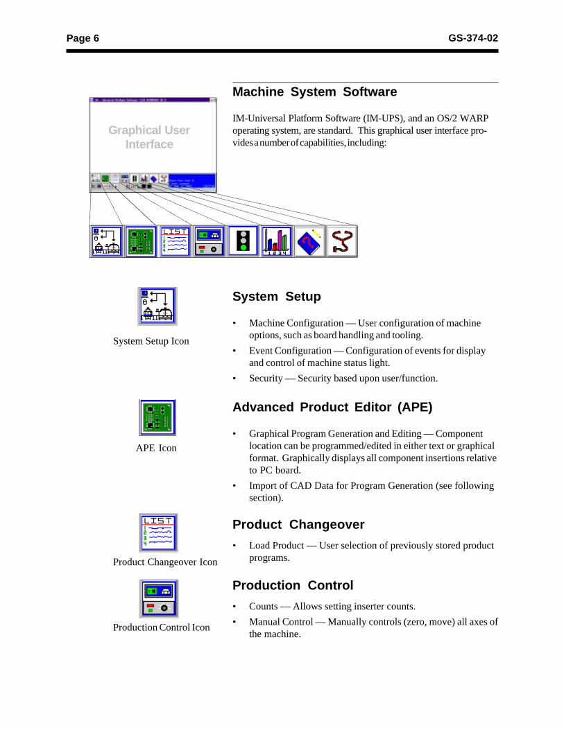
Machine System Software
IM-Universal Platform Software (IM-UPS), and an OS/2 WARPoperating system, are standard. This graphical user interface pro-vides a number of capabilities, including:
System Setup
• Machine Configuration — User configuration of machineoptions, such as board handling and tooling.
• Event Configuration — Configuration of events for displayand control of machine status light.
• Security — Security based upon user/function.
Advanced Product Editor (APE)
• Graphical Program Generation and Editing — Componentlocation can be programmed/edited in either text or graphicalformat. Graphically displays all component insertions relativeto PC board.
• Import of CAD Data for Program Generation (see followingsection).
Graphical UserInterface
Product Changeover
• Load Product — User selection of previously stored productprograms.
Production Control
• Counts — Allows setting inserter counts.
• Manual Control — Manually controls (zero, move) all axes ofthe machine.
Product Changeover Icon
Production Control Icon
APE Icon
System Setup Icon

Page 7GS-374-02
Machine Status Ison
Management Information Icon
IM Diagnostics Icon
On-Line Documentation Icon
Machine Status
• Current Messages — Displays current controller messagesand events.
• Product Status — Displays status of running product.
• Analytic Information:
• Discrete I/O — Ability to read each input and set eachoutput individually.
• Message History — Ability to view message log.
• Operations — Sets machine modes: Step, Single Cycle,Insert, Pattern.
• Error Recovery — Recovery processes for operationalerrors, i.e., mis-insertion.
Management Information
• Timers — Collection and display of machine timers.
• Counters — Count of machine events: insertions, inserterrors, boards, Bad Board Reject, Board Error Correction,circuits.
• Component Data — Counts by component ID: placements,errors.
From these databases, a variety of reports can be created.
IM Diagnostics
• IM Diagnostics — Ability to exercise machine sub-systemson an individual or combined basis outside of machine controlsoftware.
• B.E.C. Set-Up/Analysis.
• Machine Set-Up Support.
On-Line Documentation
• IM-UPS documentation is available on-line.

Page 8 GS-374-02
BOM-CAD Link: A user-defined alphanumeric stringwhich links a line of data in the CAD file to a component IDin the Bill of Material (BOM) file.
Ignore: If the CAD file contains data that does not fit anyof the fields, IM-UPS may be configured to ignore this data.
A sample CAD file format is given with a brief explanation.This file format is provided for reference only and is anexample of a typical CAD output.
CAD Data Requirements
ASCII File Format — Incoming CAD files must conform tothe American National Standard Code for InformationInterchange (ASCII). In order to accommodate a widevariety of CAD file formats, the APE uses either a genericcolumnar or separator data translation technique. All datacontained in the CAD file is identified by a position in adefinition created by the user.
CAD File Requirements
X Coordinate: The X centroid coordinate location on theboard.
Y Coordinate: The Y centroid coordinate location of thecomponent insertion.
Theta: The rotation of the component on the board.
Insertion Lead Span: The distance between thecenterlines of the component leads.
Reference ID: The name assigned to the componentmakes it unique to all other components in the product.
Component ID: The name of the component as it is foundin the component database.
Alias ID: The name of a component in the database towhich this component is aliased (optional).
Centroid (Top View)
X, Y
Length = "L"L2
L2

Page 9GS-374-02
This is a typical CAD file which may be output from a wide variety of different CAD systems.
This file includes SMC and IMC information, with component information stored for the IMC components.The component information for Surface Mount components will be obtained from the master .DEF files.IMC component information will be obtained from this file and placed into the Component Library.
Information in the CAD file:A = REFERENCE DESIGNATOR F = SPANB = X COMPONENT CENTROID COORDINATE G = NUMBER OF LEADSC = Y COMPONENT CENTROID COORDINATE H = AXIAL BODY DIAMETERD = ORIENTATION I = MACHINE TYPEE = PART NUMBER/COMP ID J = DIP SOCKET
K = AXIAL LEAD DIAMETER

Page 10 GS-374-02
Sample CAD File Format Notes
1. Maximum file width can not exceed 256 columns.
2. Headerlines, often output by the CAD system, may be used.The CAD Translator allows the user to define the quantity oflines containing the file header. This information is foroperator use only and is not used by the CAD Translator.
3. Format Type: The format of file. This can be either Tableor Separator format (Table is the default).
Table format uses predefined columns for each data type. Forexample, the reference ID column may be defined as 10 characters.The actual reference ID in the CAD file can contain up to 10characters. It does not matter if there is data in every column.
Separator format uses a character (comma, space, dash, etc.) toseparate data fields. Each line of data must contain the samedata types in order for auto detect to work.
# of Fields: The number of fields in the file.
# of Lines: The total number of lines in the file.
4. The CAD file must be devoid of all special control characterssuch as Tabs. (Note that special characters shown are forillustration purposes only and cannot be contained in theactual CAD file. These characters include boxes, arrows.)
5. CAD data is limited to one component per data file line orrow. Additional components are specified on additional linesof the CAD file. There must be no blank lines or rowsbetween any rows of CAD data. Markers such as {EOF}must not be present at the end of the CAD file.
Additional APE Features
• Import of Existing UICS Patterns — UICS patterns areconverted to IM-UPS products.
• Program Optimization — Optimization via “NearestNeighbor” insertion path.
• Component Identifier (part number) and ReferenceDesignator are now included in Product Information — theaddition of component identifier and reference designator inprograms supports improved status message reporting andmanagement data tracking by component identifier.
Product program generation is recommended to be off line from the machine since the machine cannot run in full pro- duction mode while in the Program Generation/Edit Mode. A 486-based P.C. with OS/2 Warp operating system is recom- mended. Supplied software is loadable into the machine as well as an off line P.C.

Page 11GS-374-02
Off-Line Pattern ProgrammingSpecifications
The creation of a “product” (pattern program) can be completedon-line, utilizing the machine’s embedded P.C., or off-line, using asuitable stand-alone P.C. loaded with IM-UPS software.
Universal recommends that pattern programming be generatedoff-line to eliminate production interruptions. The stand-aloneP.C. for off-line pattern program generation is not a standardfeature of the machine.
Note: IM-UPS software supplied with the machine is licensedonly for use in the machine. Software for an off-line P.C. isavailable as an option at extra cost.
Minimum P.C. requirements for creating the product off-line(pattern programming) include:• 486 processor
• 12 megabyte memory
• CD-ROM drive
• IBM OS/2 Warp 4.0
• 200 megabyte available disc space, on OS/2-compatiblepartition
For optimum performance in generating the pattern programmingoff-line, the following capabilities are recommended:• Intel Pentium® processor
• 16 megabyte memory
• 500 megabyte available disc space, on OS/2-compatiblepartition
Note: Installation of OS/2 on an existing P.C. system may re-quire partitioning of the hard drive.

Page 12 GS-374-02
System Mechanics
X-Y Positioning System
The X-Y positioning system locates the printed circuit board un-der the insertion tooling and is equipped with dual rotary indexingtables that index in 90° increments, from 0° to 360° in a clock-wise rotation. These rotary tables are air motor driven under pat-tern program control and require less than one second to executeeach 90° rotation.
The X-Y positioning system employs high performance brushlessmotors. The system is controlled by the 680X0-based motioncontrollers. Automatic belt tensioning assures that belts are prop-erly adjusted.
Machine Console/Covers
The machine covers serve two primary purposes. The first is toprovide safety by preventing access to dangerous mechanical andelectrical hazards. The second is to further reduce the soundlevel of the operating machine. It is important that the machinecovers remain in place and fully functional for operational safety.
On stand-alone machines (non board handling machines), the po-sitioning system and work board holders are exposed to allow theoperator to load and unload printed circuit boards. There is ahinged cover that protects the operator from the moving parts ofthe insertion heads. This cover is interlocked and will stop themachine if moved. Note: This configuration does not carry theCE mark. These covers are not made of an electrostatic dissipa-tive material.
Board handling machine covers completely enclose the machine.The sliding covers on the front of the machine are interlockedwith shot pins. The purpose of the shot pins is to prevent inter-lock conditions during machine operation. To gain access to themachine, the stop button on the Push Button Panel must bepressed. The machine will stop and the shot pins will be releasedfrom the covers, allowing them to be opened. Note: This con-figuration does carry the CE mark. These covers are not madeof an electrostatic dissipative material.
Note: Covers that are made of an electrostatic dissipative mate-rial are available as an option, at extra cost, for both stand-aloneand board handling machines.

Page 13GS-374-02
Machine Status Light
The machine status light indicates the status of machine opera-tion. Each light is user configurable via the monitor/keyboard in-terface. Defaults are set as follows:
• Red - machine stop for any error.
• Yellow - normal operation, machine waiting.
• Green - normal operation, machine running.
• Blue - not configured for VCD DH 8.
Insertion Head
A servo motor activates each insertion head through a rack andpinion drive, providing insertion rates up to 20,000 componentsper hour. Close coupled software provides controlled accelera-tion/deceleration and velocity during the insertion process for in-creased reliability and reduced noise.
The machine handles varying component body diameters by soft-ware selectable depth stops. Depth stops, at insertions, are soft-ware selectable via the Advanced Product Editor and based oncomponent size, programmable in 0.03mm (0.001") increments,from 0mm to 5.49mm (0" - 0.216"). Actual driver tip down posi-tion is controlled through the closed loop servo drive system.
Insertion Hole Span
The tooling span for component insertion is automatically calcu-lated by the Advanced Product Editor and based on lead diam-eter and center to center hole spacing on the PC board. Insertionhole spans are dependent upon head tooling configuration andcomponent input class and are variable under servo program con-trol.
Refer to Technical Specifications section for insertion hole spanranges that apply to the four basic tooling types.

Page 14 GS-374-02
Insertion Tooling
Universal offers four types of insertion tooling: standard, largelead, 5mm, and 5.5mm. Tooling type is selected to provide opti-mum performance depending upon board density (footprint),component lead wire size and material, component body size, holespans, and board configurations.
Standard, large lead, 5mm, and 5.5mm tooling have been de-signed for improved reliability, longer tooling life, and better han-dling of bent lead component input. This tooling incorporatesgenerous amounts of carbide inserts and has increased cross-sections for greater robustness.
Refer to Technical Specifications section for tooling specifica-tions.
Above board clearance beneath the retracted tooling is approxi-mately 20.32mm (0.800"). See Tooling Footprints and Compo-nent Clearances sections relating to tooling footprints.
Standard Tooling
Standard tooling is designed to insert components with leads from0.38mm (0.015") to 0.81mm (0.032") in diameter and hole spansfrom 7.62mm (0.300") to 22.43mm (0.883") at standard inputclass. (Maximum hole span, which is dependent upon componentinput class, is 32.44mm [1.277"]).
Refer to Technical Specifications for a specific application.
Large Lead Tooling
Large lead tooling is designed to insert components with leadsfrom 0.63mm (0.025") to 1.07mm (0.042") in diameter and holespans from 7.62mm (0.300") to 22.17mm (0.873") at standard in-put class. (Maximum hole span, which is dependent upon compo-nent input class, is 31.95mm [1.258"]).
While increasing the insertion ability for large leaded components,this tooling reduces the allowable component density during PCboard assembly.
Refer to Technical Specifications for a specific application.

Page 15GS-374-02
5mm Tooling
5mm tooling is designed to insert components with leads from0.38mm (0.015") to 0.81mm (0.032") in diameter and hole spansfrom 5.0mm (0.197") to 20.00mm (0.787") at standard inputclass. (Maximum hole span, which is dependent upon componentinput class, is 29.89mm [1.177"]).
Refer to Technical Specifications for a specific application.
5.5mm Tooling
5.5mm tooling is designed to insert components with leads from0.38mm (0.015") to 0.81mm (0.032") in diameter and hole spansfrom 5.5mm (0.216") to 20.00mm (0.787") at standard inputclass. (Maximum hole span, which is dependent upon componentinput class, is 29.89mm [1.177"]).
This tooling selection provides wider driver tips for more leadcontact and improved insertion reliability when the application re-quires 5.5mm (0.216") hole spans, rather than 5.0mm (0.197")hole spans.
Refer to Technical Specifications for a specific application.
Scrap Tape Remover
For ensured and continuous removal of scrap tape and leads fromthe rear of the machine, this roller system works with a 24 VACmotor, 50/60Hz, and is internal to the machine covers.
Cut and Clinch
The VCD DH 8 cut and clinch contains a servo-driven rocker/slide up/down mechanism and provides PC board support duringthe insertion cycle, then trims and clinches the component leadsto the underside of the PC board with a pneumatic actuated cut-ter.
Two-step operation allows the clinch to return to its lowest posi-tion during a table rotation and only half the distance during theinsertion process, saving time and wear on mechanical parts.“Half-down” position clearance between the clinch and PCB is7.62mm (0.300") and “full-down” clearance is 15.24mm (0.600").
Insertion span is servo controlled over the same span as the in-sertion head, and left and right anvils are coupled. Clinch angle isinward and may be adjusted over a range from 0º to 45º from thePC board bottomside.

Page 16 GS-374-02
Clinch lead length is adjustable from 1.28mm (0.050") to 1.80mm(0.071"). Lead length is measured from the center of the hole tothe end of the lead. The tolerance on the lead length is ±0.29mm(0.011").
The VCD DH 8 cut and clinch uses a dual lead continuity checkto verify component insertion. The failure of either lead to passthrough the PC board and be clinched will generate an insert er-ror and cause the machine to stop.
Board Error Correction AlignmentTemplate
The Board Error Correction Alignment template is required, oneper customer location, for set-up of head to table alignment. Thetemplate must be mounted on the rotary table to align first Head1 and then Head 2. This template is then used to calibrateB.E.C. (Board Error Correction) on Head 1. On pass throughmachines, the template is also used for tooling pin set-up.
The template has been redesigned to ease manufacturing set-upby removing variability from the process and providing consistentaccuracy. On pass through machines, the template has been de-signed so removal of the front guide assembly is no longer re-quired, saving time and simplifying the process. It also provides a1.57mm (0.62") edge to simulate PC board thickness, aiding insetting correct tooling pin location. The template eliminates theneed for the X-Y Table Setup Bug and provides additional, tightertoleranced, tooling pin holes to check for skew and proper rota-tion about the rotary disc’s center.
Input Components
Available for Tape Reels or Amno Pack (selectable).
ClinchLength Clinch
Length
Clinch Pattern Options
0° Clinch 45° Clinch

Page 17GS-374-02
Optional FeaturesWorkboard Holders
Workboard holders are required, but must be ordered as separateitems. The workboard holders used with the model 6292C arethe standard dual positioning Universal 457mm x 457mm (18" x18") style. Workboard holder ordering information is contained inGS-134. Workboard holders are not required when ordering theBoard Handling System, as they are included.
Automatic Board Handling Configurations
TheVCD DH 8 is available in several material handling configu-rations (left-to-right, or right-to-left):n Loader/Unloader: Magazine-to-Magazine with Short Buffer
(not CE-compliant), or with Long Buffer with extra costcovers (CE-compliant).
n Loader/Unloader: Vacuum Bare Board-to-Magazine withShort Buffer (not CE-compliant), or with Long Buffer (notCE-compliant).
n Loader/Unloader: PCB Destacker-to-Magazine.
• Destacker on 29" Conveyor with Short or Long Buffer(not CE-compliant).
• Destacker on 44" Conveyor with Short Buffer (not CE-compliant).
• Destacker on 44" Conveyor with Long Buffer with extracost covers. Input PCBs, including any installedcomponents, can not exceed 25.4mm (1") thickness (CE-compliant).
• Destacker on 58" Conveyor with Long Buffer with extracost covers (CE-compliant).
n Internal Board Handling System (BHS) - Internal BHS forin-line systems integration is also available. Two PC boards,one for input and one for output, quickly and reliably transfer.Board transfer from last insertion to first insertion on the nextboard occurs in 5.0 seconds. Transfer direction may bespecified when ordering the machine, prior to manufacture,and quick and easy manual width adjustment handles a widerange of PC board sizes. The front fixed rail is standard andall operator PC board changeover adjustments are readilyaccessible.

Page 18 GS-374-02
Network Kit
Package for connection includes Ethernet network card and IBMOS/2 TCP/IP client software. This provides high speed, reliablecommunications and data transfer to all computers connected tothe network.
Host Computer Interface Kit
This kit is used to interface VCD DH 8 with a Host computer us-ing the SECS/GEM Standard. The Generic Equipment Model(GEM) Standard defines a standard implementation of the SECSII (Semi Equipment Communications Standard 2) communica-tions interface for all semiconductor manufacturing equipment.See SEMI International Standards document E30-93 for details.Note: Requires customer’s Host computer to be compliant withSECS/GEM standard SEMI E37, HSMS.
Remote P.C. Software/Off-LineProgramming
Each base machine includes software licensed only to the ma-chine. Universal recommends that “product” programs be cre-ated off-line to ensure maximum use of machine production time.This off-line software is licensed for use on a P.C. with a basicconfiguration as shown in the “Off-Line Pattern ProgrammingSpecifications” found on page 11 of this document.
Remote P.C.
The Universal Control Terminal (UCT), using optional IM-UPSsoftware, allows a Universal approved personal computer to beused as an intelligent terminal. It is connected to the VCD DH 8via the optional Network Kit. This package includes a visual dis-play terminal, keyboard, data storage unit, printer and stand, cableassembly, and manual. For additional information on this option,refer to GS-319. This can be used for off-line programming andmachine data transfer.

Page 19GS-374-02
Supporting Documents
GS-055 Indexing Rotary TablesGS-061 Lead Tape Reel Packaging of Axial Compo-
nents, Series 2500GS-134 Workboard Holders, Series 6810GS-354-01 Through Hole Design GuidelinesEIA RS-296-E Lead Taping of Components in Axial Configura-
tion for Automatic Insertion

Page 20 GS-374-02
A = TAPE SPACING D = COMPONENT BODY DIAMETER - notes 2, 3Input Class Distance Between TapesStd 43.7mm (1.72") E = COMPONENT SPACING
5.08MM (0.200")B = HOLE SPAN - hole center distance, 10.16mm (0.400"), note 3
notes 1, 2F = COMPONENT LEAD DIAMETER
C = COMPONENT BODY LENGTH
Notes:
1. The recommended maximum consecutive plus hole span change is 5.08mm (0.200") to prevent leadscrap problems. There is no limit to consecutive minus hole span change.
2. At 5mm hole spans, the maximum component body diameter is 2.29mm (0.090").
3. Optional 10.16mm (0.400") pitch wheels on dispensing heads are available.
Component Definitions
Input Specifications for the VCD Insertion Head
F
C
A
E
note 1
B
Directionof componentfeed
Scrap as it leavesinsertion head
Point ofinsertion
B
Componentsbefore reachinginsertion head
note 2,3
OutsideFormer
D
Technical Specifications

Page 21GS-374-02
Insertion Tooling Specification 1
Standard Large Lead 5mm 5.5mm
Minimum Hole Span 2 7.62 (0.300) 7.62 (0.300) 5.00 (0.197) 5.50 (0.216)(with minimum leaddiameter)
Maximum Hole Span 2 Std Input Tape 22.43 (0.883) 22.17 (0.873) 20.00 (0.787) 20.00 (0.787)(with maximum leaddiameter shown byinput class)
Steel Wire Lead Size Minimum 0.38 (0.015) 0.63 (0.025) 0.38 (0.015) 0.38 (0.015)Maximum 0.81 (0.032) 0.81 (0.032) 0.81 (0.032) 0.81 (0.032)
Copper Wire Lead Size Minimum 0.38 (0.015) 0.64 (0.025) 0.38 (0.015) 0.38 (0.015)Maximum 0.81 (0.032) 1.07 (0.042) 0.81 (0.032) 0.81 (0.032)
Component Body Minimum Wire lead dia. Wire lead dia. Wire lead dia. Wire lead dia.Diameter Maximum 3 10.69 (0.420) 10.69 (0.420) 11.68 (0.460) 11.68 (0.460)
minus 2 X minus 2 X minus 2 X minus 2 Xboard board board boardthickness thickness thickness thickness
1 Dimensions are given in millimeters; inches are in parentheses. 2 Insertion hole span is defined as the hole center distance. Wider insertion spans are possible with the use of wider tape spacing. Consult a Universal Sales Engineer. 3 At 5mm and 5.5mm hole spans, maximum component body diameter is 2.29mm (0.090").

Page 22 GS-374-02
Component Body Length Considerations
After the tooling type and the variables have been determinedfrom the Insertion Tooling Specification table, the minimum al-lowable hole span can be determined for a known body length.
Machine capabilities allow components to be inserted using theminimum hole span formulas below. Due to body length varia-tions, it is recommended to design hole spans greater than thecalculated minimum.
Use the following formulas, depending on tooling type -- standard,large lead, 5mm, or 5.5mm -- to calculate the minimum insertionhole span for a known body length. The formulas apply to thebody length ranges shown and are based on a ±0.41mm (0.016")component centering accuracy on the input tape.
Minimum Insertion Hole Span Formulas for Maximum Body LengthsStandard Tooling [Body Length Range: 5.08mm (0.200") to 15.75mm (0.620")]
Metric Formula: Minimum Hole Span = [(Component Body Length1 x 1.112) + 2.36mm] - Lead Diameter
Inch Formula: Minimum Hole Span = [(Component Body Length1 x 1.112) + 0.093"] - Lead Diameter
Large Lead Tooling [Body Length Range: 3.81mm (0.150") to 15.75mm (0.620")]
Metric Formula: Minimum Hole Span = [(Component Body Length1 x 1.085) + 4.11mm] - Lead Diameter
Inch Formula: Minimum Hole Span = [(Component Body Length1 x 1.085) + 0.162"] - Lead Diameter
5mm Tooling [Body Length Range: 3.61mm (0.142") to 15.75mm (0.620")]
Metric Formula: Minimum Hole Span = [(Component Body Length1 x 1.109) + 1.40mm] - Lead Diameter
Inch Formula: Minimum Hole Span = [(Component Body Length1 x 1.109) + 0.055"] - Lead Diameter
5.5mm Tooling [Body Length Range: 3.61mm (0.142") to 15.75mm (0.620")]
Metric Formula: Minimum Hole Span = [(Component Body Length1 x 1.067) + 2.03mm] - Lead DiameterInch Formula: Minimum Hole Span = [(Component Body Length1 x 1.067) + 0.080"] - Lead Diameter1 Subtract an additional 0.41mm (0.016") from the maximum body length for non-symmetrically shaped
components.
HOLE SPAN

Page 23GS-374-02
A
B C
D
C
Note:Dimension A is measured at the smallest possible footprint for 5mm and 5.5mm tooling. See Tooling Footprints for related dimensions.
Recommended Component Clearances 1
Standard Large Lead 5mm & 5.5mm
Lead 0.38 0.81 0.63 1.07 0.38 0.81Diameter (0.015) (0.032) (0.025) (0.042) (0.015) (0.032)
A Dimension 1.78 2.01 1.80 2.08 0.97 1.22(0.070) (0.079) (0.071) (0.082) (0.038) (0.048)
B Dimension 1.14 (0.045) 1.57 (0.062) 1.14 (0.045)
C Dimension 0.25 (0.010) 0.25 (0.010) 0.25 (0.010)
D Dimension 0.76 (0.030) 0.76 (0.030) 0.76 (0.030)1 Dimensions are given in millimeters; inches are in parentheses.

Page 24 GS-374-02
Insertion Tooling Footprint
6.35 (0.25)
3.81 (0.150)
0.48 (0.019)
2.29 (0.090)
2.29 (0.090)
Tooling FootprintStandard Large Lead 5mm and 5.5mm
Fron
t Vie
wS
ide
Vie
wB
otto
m V
iew
0.84 (0.033)
3.18 (0.125)
2.36 (0.093)
0.48 (0.019)
1.27 (0.050)
2.29 (0.090)
2.29 (0.090)
12.19 (0.489)
2.29 (0.090)
6.35 (0.25)
6.35 (0.25) 3.81 (0.150)
1.27 (0.050)
15o
Dimensions are in millimeters;inch equivalents are bracketed.
2.36(0.093)
1.27(0.050)15°

Page 25GS-374-02
Cut and Clinch Footprint
Dimensions are in millimeters;inch equivalents are bracketed.
Page 26 GS-374-02
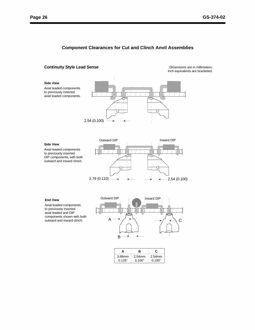
Component Clearances for Cut and Clinch Anvil Assemblies
Side View
Axial leaded componentsto previously insertedaxial leaded components.
Side View
Axial leaded componentsto previously insertedDIP components, with bothoutward and inward clinch.
End View
Axial leaded componentsto previously insertedaxial leaded and DIPcomponents shown with bothoutward and inward clinch.
A B C
3.68mm 2.54mm 2.54mm 0.125" 0.100" 0.100"
A
B
C
2.54 (0.100)
2.79 (0.110) 2.54 (0.100)
Outward DIP Inward DIP
Outward DIP Inward DIP
Continuity Style Lead Sense Dimensions are in millimeters;inch equivalents are bracketed.

Page 27GS-374-02
Board Error Correction Detection Area
Due to the position of the Board Error Correction sensor relativeto the insertion point, there is an area which cannot be scannedby the sensor. The non-scannable area is at the rear of the posi-tioning system regardless of rotary table rotation.
Auto MisMark
Due to the position of the Auto MisMark relative to the insertionpoint, there is an area which cannot be marked by the marker.The non-markable area is at the rear and right of the positioningsystem, regardless of rotary table rotation.
457.2mm(18.000")
457.2mm(18.000")
BEC sensoroffset
22.86mm(0.900")
+X
+Y
22.86mm(0.900")
457.2mm x 457.2mm (18" x 18")insertable area(less corners)
Insertioncenterline
69.85mm(2.75") TYP
The shaded area cannot be scannedby Board Error Correction sensor
Front of Machine
38.1mm(1.500")
8.89mm(0.350")
Page 28 GS-374-02
Insertion Rate Determination
Insertion RateUp to 40,000 insertions per hour with standard, large lead, 5mm, and5.5mm tooling, with factory test specifications, and insertion PPM of150 or better.
To attain the maximum insertion rate, the X and Y axis move betweenconsecutive pattern steps must be no more than 7.5mm (0.300"). Aninsertion span move greater than 2.54mm (0.100") will degrade speed.
In the Production Operating Mode, the machine will automaticallycalculate the insertion rate for each set of PCBs processed. This actualinsertion rate includes all table rotations from first insert to last insert ofa product (program). It does not include PCB transfer time.
Positioning SystemTable Size 457mm x 457mm (18" x 18")
Insertable Area 457mm x 457mm (18" x 18"), less corners.See appendix for dual head board handlingsystem details.
Accuracy ±0.05mm (±0.002")
Repeatability ±0.025mm (±0.001")
Table Capacity 22.7 kg (50 pounds) maximum, includingworkboard holder.
Programming ±0.01mm (metric dimensioning)Capability ±0.001" (inch dimensioning)
Speed 368mm (14.5") per second7.62mm (0.3") in 0.070 seconds
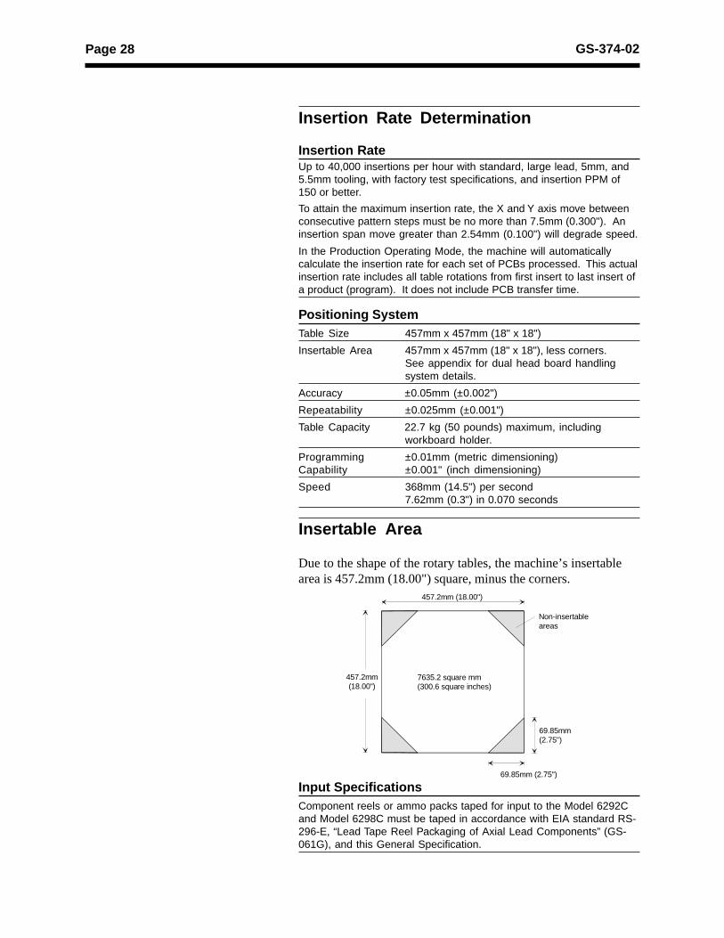
Insertable Area
Due to the shape of the rotary tables, the machine’s insertablearea is 457.2mm (18.00") square, minus the corners.
457.2mm (18.00")
69.85mm (2.75")
Non-insertable areas
7635.2 square mm(300.6 square inches)
69.85mm (2.75")
457.2mm(18.00")
Input SpecificationsComponent reels or ammo packs taped for input to the Model 6292Cand Model 6298C must be taped in accordance with EIA standard RS-296-E, “Lead Tape Reel Packaging of Axial Lead Components” (GS-061G), and this General Specification.

Page 29GS-374-02
Stand-Alone Installation Considerations
Machine Shipping DimensionsLength Depth Height Weight
2134mm 1549mm 1473mm 1050.07kg(84") (61") (58") (2315 lbs.)
Domestic 2591mm 1829mm 1549mm 1334.02kgShipping (102") (72") (61") (2941 lbs.)
Air Freight 2616mm 1854mm 1676mm 1324.49kg(103") (73") (66") (2920 lbs.)
Sea Freight 2616mm 1854mm 1676mm 1447.41kg(103") (73") (66") (3191 lbs.)
Floor Space A minimum clear area of one meter (three feet)around the machine perimeter is recommendedfor machine operation and servicing.
Operator
P
E
P E
Pneumatic connection
Electrical connection
1549 (61)
Allow one meter (three feet) around
entire machine for work space.
2134 (84)
Dimensions are in millimeters;inch equivalents are bracketed.
483 (19)
UPS 610(24)
305(12)

Page 30 GS-374-02
VCD DH 8, Non Pass Through: Side View
Dimensions are in millimeters;inch equivalents are bracketed.
1371.6 (54.0)
650.2(25.5)
1333.5 (52.5)
851.0 (33.5)
1549.4 (61)
977.9(38.5)
673.1 (26.5)
1028.7 (40.5)
520.7 (19.5)
50.8 (2)

Page 31GS-374-02
Service Requirements (including UninterruptablePower Supply)
Electrical (base machine)
Electrical connection located in the back of themachine, 482.60mm (19") from the right side and660.40mm (26") from the floor.
Machine is shipped with a power cord frommachine to Uninterruptable Power Supply. Amating connector is supplied to attach the userprovided power cord to the UPS.
The UPS has an external 5mm ground stud whichmust be permanently connected to earth/buildingground with a 14 AWG or 2.5mm2 wire that isappropriately protected from mechanical damage.
A circuit breaker is the overcurrent device for boththe machine and the UPS. The machine breakerhas a short circuit interrupting capacity of10,000A, and the UPS breaker has a short circuitinterrupting capacity of 1000A.
The branch circuit supplying the machine must beprotected by an approved 15 amp circuit breakerwith a delay suitable for "high inrush current" or"transformer loads."
Air Consumption A quick disconnect with a male barbed fitting for12.7mm (0.50") ID flexible hose is shipped witheach machine.
Pneumatic connection located in the back of themachine, 482.60mm (19") from the right side and660.40mm (26") from the floor.
Air Quality Non-lubricated, dry air, maximum contaminationparticle size of 5.0 microns.
Note:
• Without loader/unloader, for voltages other than 230 VAC, current is 1150 VA (inputvoltage). Power factor may vary with input voltage.
• With loader/unloader, for voltages other than 230 VAC, current is 1610 VA (input voltage).Power factor may vary with input voltage.
• CFM (Cubic Feet per Minute): Volumetric flow rate at a specified pressure. This is used todescribe the air flow requirement.
• SCFM (Standard Cubic Feet per Minute): Cubic foot of air at 20° C (68º F) at atmosphericpressure. This is used to describe average air consumption flow requirement.
PNEUMATIC REQUIREMENTS(Base Machine) ELECTRICAL REQUIREMENTS
Minimum Air FlowRequirements
AirConsumption
UPSInput
Voltage
InputFrequency
InputBreaker
Actual PowerDraw Without
Loader/Unloader
Actual PowerDraw With
Loader/Unloader
1.4 CFM @ 90 PSI 8.7 SCFM180 - 264
VAC,SinglePhase,1ø
47 - 63 Hz 15A1150 VA
5A @ 230 VAC1610 VA
7A @ 230 VAC

Page 32 GS-374-02
Environmental RequirementsAmbient 10° C. to 35° C.Temperature (50° F. to 95° F.)
Operating 10% to 90%, non-condensingHumidity
Contaminants The machine, UPS included, carries an IP coderating of 20. IP 20 signifies that the equipmenthas limited protection against ingress of solidforeign objects and is not protected against theingress of water. Consequently, the intendedenvironment is that of manufacturing/officewhere the machine is not subject to suchelements.
Transportation -25° C to +55° C. (-13° F. to +131° F.); notand Storage exceeding 24 hours up to 70° C. (158° F.), 10%
to 95%, non-condensing humidity.
Universal provides suitable means to preventdamage from humidity, vibration, stress andshock during transport.
Noise Level, 71 dbA in accordance with National MachinePass Through Toolbuilders Assoc. Noise MeasurementConfiguration Technique Standard — June 1986.
Noise Level, 78.2 dbA in accordance with National MachineNon Pass Through Toolbuilders Assoc. Noise MeasurementConfiguration Technique Standard — June 1986.

A - 33GS-374-02, Appendix: Automatic Board Handling Systems
Index
Appendix: Automatic Board Handling Systems
Introduction .......................................................................................................... A-34Board Handling Interface Standard ..................................................................... A-35Technical Specifications for Internal Board Handling System (BHS) ............... A-36VCD DH 8 with Internal BHS Only ....................................................................... A-38Technical Specifications for Loader/Unloader:
Elevator/Buffer Configuration ....................................................................... A-40Universal Magazine Specifications ..................................................................... A-42Magazine-to-Magazine Configuration, with Long Buffer .................................... A-43Magazine-to-Magazine Configuration, with Short Buffer ................................... A-44Technical Specifications for Loader/Unloader:
Vacuum Bare Board-to-Magazine Configuration ......................................... A-45Vacuum Bare Board-to-Magazine Configuration, with 22" Conveyor and Long
Buffer .............................................................................................................. A-46Vacuum Bare Board-to-Magazine Configuration, with 22" Conveyor and Short
Buffer .............................................................................................................. A-47Technical Specifications for Loader/Unloader:
Destacker / Conveyor-to-Magazine Configuration ........................................ A-48Destacker / Conveyor-to-Magazine Configuration,
with Long Buffer ............................................................................................ A-49Destacker / Conveyor-to-Magazine Configuration,
with Short Buffer ............................................................................................ A-50Installation Considerations: Loader/Unloader .................................................... A-51Service Requirements .......................................................................................... A-52

A - 34 GS-374-02, Appendix: Automatic Board Handling Systems
Introduction
The VCD DH 8 (Model 6292C), is available either as stand-alone or with internal board handling only, for in-line configura-tion.
n In-Line Configuration: Machines can be connected in-lineusing the internal Board Handling System (BHS) and intercon-necting conveyors. The BHS transfers two PC boards at a time:unpopulated boards in, and populated boards out. All BoardHandling Systems are factory configurable for either left-to-right or right-to-left direction. This configuration is CE-compli-ant.
Auto MisMark and a Bad Board Reject Station allow PC boardswith misinserted components to be automatically marked at thetime of misinsertion and stacked off-line for later repair. Whencomplete, the PC boards are transferred out of the machine andinto the output magazine. When full, the output magazine is au-tomatically transferred to the buffer conveyor.
The VCD DH 8 (Model 6298C) is available in a number of automaticboard handling configurations:
n Magazine-to-Magazine Configuration: Magazines contain-ing PC boards are placed on the input Elevator (Loader) and thePC boards are then automatically transferred into the machinefor component insertion. Once completed, the boards areunloaded into an output magazine Elevator (Unloader). EachElevator includes a magazine Buffer. Buffers are available intwo sizes:
• Long Buffer: 1270mm (50") for magazines up to 21" long(CE-compliant)
• Short Buffer: 1016mm (40") for magazines up to 16" long(not CE-compliant)
n Vacuum Bare Board-to-Magazine Configuration: BarePC boards are placed in a Vacuum Bare Board Loader and thePC boards are then automatically transferred onto a 558mm(22") conveyor, which transports them into the machine forcomponent insertion. Once completed, the boards are unloadedinto an output magazine Elevator (Unloader). The output Eleva-tor includes a Long or Short Buffer (as above); neither of theseconfigurations is CE-compliant. Note: This unit is bestsuited for PC boards with eyelets.
n Destacker/Conveyor-to-Magazine Configuration: BarePC boards are placed in a Destack Loader and the PC boardsare then automatically dropped onto a 736.6mm (29"), 1117.6mm(44"), or 1473.2mm (58") conveyor, which transports them into

A - 35GS-374-02, Appendix: Automatic Board Handling Systems
the machine for component insertion. Once completed, theboards are unloaded into an output magazine Elevator (Unloader).The output Elevator includes a Long or Short Buffer (as above);only the systems incorporating the Destack Loader with the1117.6mm (44") or 1473.2mm (58") conveyor, and Elevator withLong Buffer, are CE-compliant. Note: This unit will notfunction properly when eyelets are present on the PCboard.
Board Handling Interface Standard
The board handling interface standard of the VCD DH 8 isSMEMA, version 1.2.

A - 36 GS-374-02, Appendix: Automatic Board Handling Systems
Technical Specifications for InternalBoard Handling System (BHS)
Board Handling System SpecificationsMinimum Maximum
Transfer Height 1,2 1001.5mm (39.43") to 1014.2mm (39.93")
Board Changeover Manual
Direction Select right-to-left or left-to-right.
Edge Clearance 5mm (0.197") or 3mm (0.118") 3
Fixed Edge Front
Locator Pins Front
Transfer Time 4 5.0 seconds, maximum for 1007.9mm (39.68")transfer height (upper level)
Notes:1. Transfer height can be configured, and alters transfer time.
See transfer time specification.2. Dual Heads are not configurable to transfer at a lower level.3. Set at factory to 5mm.4. Time from last insertion to first insertion on next board. This
number is based on 254mm (10") positioning system moves.Larger table moves increase transfer time.
PC Board SpecificationsMinimum Maximum
Length 1 x Width 100mm x 80mm 457mm x 330mm(4" x 3.1") 2 (18" x 13") 2, 3
Length to Width 1 or greater: 1 is recommendedRatio
Thickness 0.8mm (0.032") 2.36mm (0.093")
Warp — 3.17mm (0.125")
Cutouts Contiguous edges
Datum Hole 3.17mm (0.125") 2 6.35mm (0.25") 2
Diameter
Weight 2.27kg (5 lbs.), maximum
Notes:1. Length is in the direction of board flow.2. Consult a Universal Sales Engineer for other than stated
sizes.3. Board widths larger than 297mm (11.70") require removal of
270° Rotary Table stop block.
WidthMin. 80mm (3.1")
Max. 330mm (13")
LengthMin.100mm (4")
Max. 457mm (18")
Direction of Board Flow
Operator

A - 37GS-374-02, Appendix: Automatic Board Handling Systems
Table Rotation (Dimensions shown are for standard tooling)0° 90° 180° 270°
A 5.99mm (0.236") 1 7.59mm (0.299") 2 9.27mm (0.365") 1 7.59mm (0.299") 2
B 7.09mm (0.279") 2 5.49mm (0.216") 1 7.09mm (0.279") 2 5.49mm (0.216") 1
C 7.09mm (0.279") 2 8.76mm (0.345") 1 7.09mm (0.279") 2 8.76mm (0.345") 1
D 7.09mm (0.279") 2 5.49mm (0.216") 1 7.09mm (0.279") 2 5.49mm (0.216") 1
E 7.09mm (0.279") 2 8.76mm (0.345") 1 7.09mm (0.279") 2 8.76mm (0.345") 1
F 5.33mm (0.210") 1, 3 5.38mm (0.212") 2, 3 5.33mm (0.210") 1, 3 5.38mm (0.212") 2, 3
G 5.33mm (0.210") 1, 3 5.38mm (0.212") 2, 3 5.33mm (0.210") 1, 3 5.38mm (0.212") 2, 3
H 3.17mm (0.125") minimum6.35mm (0.250") recommended
7.62mm (0.300") maximum
J 3.17mm (0.125") minimum3.96mm (0.156") recommended
6.35mm (0.250") maximum
1. Dimensions are to centerline of lead.
2. Dimensions are to the bottom of the 'V' groove in the former.
3. Dimension shown is for 3mm edge support. If using a 5mm edge support, add 2mm(0.079") to dimension shown.
Front at 180°
Front at 270° F
ront
at 9
0°
AB
C D
EF
G
H
diameter J
X
Dimensions shown are minimum distances from either the board edge or the tooling pin hole, to either the standard tooling or the clinch.
3mm edge support

A - 38 GS-374-02, Appendix: Automatic Board Handling Systems
Top View of VCD DH 8 with Internal BHS only
P
E
Pneumatic connection
Electrical connection
1549 (61)
Allow one meter (three feet) around
entire machine for work space.
254 (10 ) Front of board transfer
2134 (84)
3820 (151)
3721 (146.5)
Dimensions are in millimeters;inch equivalents are bracketed.
P E
483 (19)
UPS
305(12)
610(24)
Operator
Machine Shipping DimensionsLength 1 Depth Height Weight
3820mm 1549mm 1473mm 1288kg(151") (61") (58") (2840 lbs.)
Domestic 4191mm 1829mm 1549mm 1515kgShipping (165") (72") (61") (3340 lbs.)
Air Freight 4216mm 1854mm 1676mm 1696.44kg(166") (73") (66") (3740 lbs.)
Sea Freight 4216mm 1854mm 1676mm 1809.83kg(166") (73") (66") (3990 lbs.)
Floor Space A minimum clear area of one meter (three feet) around the machine perimeter is recommended for machine operation and servicing.
1. Length is in the direction of board flow.

A - 39GS-374-02, Appendix: Automatic Board Handling Systems
Dimensions are in millimeters;inch equivalents are bracketed.
VCD DH 8, Pass Through: Side View
1371.6 (54.0)
650.2(25.6)
1333.5 (52.5)
851.0 (33.5)
1549.4 (61)
208.25(8.5)
263.75(10.75)
171.5(7)
184.15(7.25)
434.875(17.75)
673.1 (26.5)
647.7 (25)
18.75(0.75)
863.8 (34)
685.8 (27)
50.8 (2)
1295.4 (51.0)
431.8 (17.0)
1778.0 (70.0)

A - 40 GS-374-02, Appendix: Automatic Board Handling Systems
Changeover Time Magazine, 20 seconds
Long Buffer
Short Buffer
PC Board The insertion machine determines board size.
Magazine ElevatorsMagazine Elevator Controlled through insertion machine software.
Power and air are supplied through the insertionmachine. Elevators are equipped withemergency stops.
Elevator Length Depth HeightDimensions 635mm (25") 838mm (33") 1,835mm
(72")
Magazine Input/Output BuffersLong Buffer The Long Buffer accomodates 2 magazines (in
and out) that are up to 533mm (21") in lengtheach.
Long Buffers are available either withCE-compliant Buffer covers or without thecovers. Covers must be affixed to the Buffers inorder for the Buffers to be CE-compliant.
Long Buffer Length Depth HeightDimensionsWith Full Covers 1,270mm 546mm 1,835mm(CE-compliant) (50") (22") (72")
Long Buffer Length Depth HeightDimensionsWithout Covers 1,270mm 546mm 1,095mm(Not CE-compliant) (50") (22") (43")
Short Buffer The Short Buffer accommodates 2 magazines (inand out) that are up to 406mm (16") in lengtheach. (Short Buffers do not accommodateUniversal magazines.)
Short Buffers are not CE-compliant.
Short Buffer Length Depth HeightDimensions 1,016mm 546mm 1,095mm
(40") (22") (43")
Magazine Transfer Upper level magazine transfer height for bothHeight Long and Short Buffers is 1,056mm (42").
Lower level Magazine transfer height for bothLong and Short Buffers is 292mm (12").
Technical Specifications for Loader/Unloader: Elevator/Buffer Configuration

A - 41GS-374-02, Appendix: Automatic Board Handling Systems
MagazinesMaximum 45kg (100lbs) for PC boards plus magazines.Magazine Weight Compatible with most commonly-used
magazines. Consult a Universal SalesEngineer.
Maximum Magazine Maximum Maximum Maximum MaximumDimensions for Length Width Height WeightLong Buffer (including
PC boards)
533mm 279mm 606mm 45kg(21") (11") (24") (100lbs)
Maximum Magazine Maximum Maximum Maximum MaximumDimensions for Length Width Height WeightShort Buffer (including
PC boards)
406mm 279mm 606mm 45kg(16") (11") (24") (100lbs)
Optional Magazine An optional magazine gate control is availableGate Control for use with magazines that include a spring-
loaded gate, used to keep PC boards retainedwithin the magazine.

A - 42 GS-374-02, Appendix: Automatic Board Handling Systems
Magazine Views
Base Pan PC Board Size Reference PC Board Guides
Width A Length BMinimum Maximum Minimum Maximum
Datum D Pitch EWidth C Length
444.5mm17.50"
476.3mm18.75"
108mm4.25"
406.4mm16.00"
149.9mm5.90"
457.2mm18.00"
35.1mm1.38"
10mm0.394"
406.4mm16.00"
476.3mm18.75"
108mm4.25"
368.3mm14.50"
149.9mm5.90"
457.2mm18.00"
35.1mm1.38"
10mm0.394"
292.1mm11.50"
476.3mm18.75"
108mm4.25"
254mm10.01"
149.9mm5.90"
457.2mm18.00"
35.1mm1.38"
10mm0.394"
19.1mm(0.75")
606.55mm(23.88")
If Universal magazines are not purchased/used, user must provide magazine specifications or,preferably, a magazine to verify proper function with Universal loaders/unloaders. The maximumallowable dimensions for third-party magazines are: L 490mm (19.29") x D 460mm (18.11") x H635mm (25.00").
Universal Magazine Specifications

A - 43
GS
-374-02, Appendix: A
utomatic B
oard Handling S
ystems
VCD DH 8, Magazine-to-Magazine Configuration, with Long Buffers
System shown in left-to-rightboard-flow configurationwith fixed front rail.
Dual Head Inserter
635 (25)
Dimensions are in millimeters;inch equivalents are bracketed.
P
E
Pneumatic Connection
546 (21.5)
838.2(33)
1270 (50)
1905 (75)
UnloaderLoader
2134 (84)
3721 (146.5)
7531 (296.5)
1539(60.6)
P
E Electrical Connection
Direction of Board Flow
UPS
Operator

A - 44
GS
-374-02, Appendix: A
utomatic B
oard Handling S
ystems
VCD DH 8, Magazine-to-Magazine Configuration with Short Buffers
System shown in left-to-rightboard-flow configurationwith fixed front rail.
Dual Head Inserter
635 (25)
Dimensions are in millimeters;inch equivalents are bracketed.E
P
E
Pneumatic connection
Electrical connection
546 (21.5)
838.2(33)
1016 (40)
1651 (65)
UnloaderLoader
2134 (84)
3721 (146.5)
7023 (276.5)
1539(60.6)
P
Direction of Board Flow
UPS
Operator

A - 45GS-374-02, Appendix: Automatic Board Handling Systems
Technical Specifications for Loader/Unloader: Vacuum Bare Board-to-Magazine Configuration
PC Board Specifications for Vacuum Bare Board LoaderMinimum Maximum
Length 1 x Width 127mm x 102mm 457mm x 406mm(5" x 4") 2 (18" x 16") 2
Length to Width >1:1 is recommended.Ratio
Thickness 0.76mm (0.030") 2.36mm (0.093")
Warp — 2.36mm (0.093")
Cutouts Contiguous edges
Stack, Maximum 250 boards at a nominal thickness of 1.57mm(0.062") is the maximum stack height of 394mm(15.5").
Notes:
1. Length is in the direction of board flow.
2. The VCD DH 8 determines board size. Consult a UniversalSales Engineer for boards larger than 356mm (14").
Vacuum Length Depth HeightBare Board 751.1mm 689.1mm 1574.8mmDimensions (29.57") (29.13") (62")
PC Board Specifications for Between Machines 22"Conveyor
Minimum Maximum
Length 1 x Width 76mm x 51mm 508mm x 457mm(3" x 2") 2 (20" x 18") 2
Length to Width >1:1 is recommended.Ratio
Thickness 0.64mm (0.025") 3.18mm (0.125")
Warp — 3.18mm (0.125")
Notes:
1. Length is in the direction of board flow.
2. The VCD DH 8 determines board size. Consult a UniversalSales Engineer for boards larger than 356mm (14").
Length Depth Height 1
22" Conveyor 559mm 802.6mm 962.7mmDimensions (22") (31.6") (37.9")
Notes:
1. Height represents pre-set transfer height of conveyor bed.Transfer height is adjustable from 812.8mm (32") to1066.8mm (42").
WidthMin. 102mm (4")
Max. 406mm (16")
LengthMin.127mm (5")
Max. 457mm (18")
Direction of Board Flow
Operator

A - 46
GS
-374-02, Appendix: A
utomatic B
oard Handling S
ystemsVCD DH 8, Vacuum Bare Board-to-Magazine Configuration, with 22" Conveyor
and Long Buffer
System shown in left-to-rightboard-flow configurationwith fixed front rail.
Elevator Module
PE
82.6(3.25 )
Vacuum BareBoard Loader
689.1(29.13 ) 802.6
(31.60)
751.1 (29.57)
Dimensions are in millimeters;inch equivalents are bracketed.
546 (21.5)
838.2(33)
E
P
EP
Pneumatic Connection
Electrical Connection
UnloaderLoader
559 (22.0)
635 (25) 1270 (50)
1905 (75)2134 (84)
3721 (146.5)
6936.1 (273.07)
1539(60.6)
Direction of Board Flow
UPS
Operator

A - 47
GS
-374-02, Appendix: A
utomatic B
oard Handling S
ystems
VCD DH 8, Vacuum Bare Board-to-Magazine Configuration, with 22" Conveyorand Short Buffer
System shown in left-to-rightboard-flow configurationwith fixed front rail.
Elevator Module
PE
82.6(3.25 )
Vacuum BareBoard Loader
689.1(29.13 ) 802.6
(31.60)
751.1 (29.57)
Dimensions are in millimeters;inch equivalents are bracketed.
546 (21.5)
838.2(33)
E
P
EP
Pneumatic Connection
Electrical Connection
UnloaderLoader
559 (22.0)
635 (25) 1016 (40)
1651 (65)2134 (84)
3721 (146.5)
6682.1 (263.07)
1539(60.6)
Direction of Board Flow
UPS
Operator

A - 48 GS-374-02, Appendix: Automatic Board Handling Systems
Technical Specifications for Loader/Unloader: Destacker/Conveyor-to-Magazine Configuration
PC Board Specifications for Destacker/ConveyorLoader
Minimum Maximum
Length 1 x Width 76mm x 51mm 508mm x 457mm(3" x 2") (20" x 18")
Length to Width >1:1 is recommended.Ratio
Thickness 1.02mm (0.040") 3.18mm (0.125")
Warp — 3.18mm (0.125")
Cutouts Require Factory Review
Stack, Maximum 190 boards at a nominal thickness of 1.6mm(0.063") is the maximum stack height of304.8mm (12").
Notes:1. Length is in the direction of board flow.2. The VCD DH 8 determines board size. Consult a
Universal Sales Engineer for boards larger than 356mm (14").
Destacker/Conveyor SpecificationsDestacker on Length Depth Height 3
29" Conveyor 1 736.6mm 802.6mm 962.7mm(29") (31.6") (37.9")
Destacker on 1,117.6mm 802.6mm 962.7mm44" Conveyor 2 (44") (31.6") (37.9")
Destacker on 1473.2mm 802.6mm 962.7mm58" Conveyor 2 (58") (31.6") (37.9")
Notes:1. Not CE-compliant.2. CE-compliant if configured with safety covers.3. Height represents pre-set transfer height of conveyor bed.
Transfer height is adjustable from 812.8mm (32") to1066.8mm (42"). Add 383.5mm (15.1") to transfer height fortotal height of Destacker sitting atop Conveyor.
WidthMin. 51mm (2")
Max. 457mm (18")
LengthMin.76mm (3")
Max. 508mm (20")
Direction of Board Flow
Operator

A - 49
GS
-374-02, Appendix: A
utomatic B
oard Handling S
ystems
System shown in left-to-rightboard-flow configurationwith fixed front rail.
802.64 (31.60)
736.6 (29.0)
Destacker/Conveyor
Loader
6362.6 (250.5)with 29" conveyor
1117.6 (44.0)
6743.6 (265.5)with 44" conveyor
Dimensions are in millimeters;inch equivalents are bracketed.
546 (21.5)
838.2(33)
1270 (50)635(25)
Unloader
1905 (75)
3721 (146.5)1473.2 (58.0)
7099.2 (279.5)with 58" conveyor
VCD/Sequencer 8
P
E Electrical Connection
Pneumatic Connection
EP
2134 (84)
1539(60.6)
Direction of Board Flow
UPS
VCD DH 8, Destacker/Conveyor-to-Magazine Configuration,with Long Buffers
Operator

A - 50
GS
-374-02, Appendix: A
utomatic B
oard Handling S
ystems
VCD DH 8, Destacker/Conveyor-to-Magazine Configuration,with Short Buffers
System shown in left-to-rightboard-flow configurationwith fixed front rail.
802.64 (31.60)
736.6 (29.0)
Destacker/Conveyor
Loader
1117.6 (44.0)
6489.6 (255.5)with 44" conveyor
Dimensions are in millimeters;inch equivalents are bracketed.
546 (21.5)
838.2(33)
635(25)
Unloader
1651 (65)
3721 (146.5)1473.2 (58.0)
6845.2 (269.5)with 58" conveyor
VCD/Sequencer 8
P
E Electrical Connection
Pneumatic Connection
EP
2134 (84)
1539(60.6)
Direction of Board Flow
UPS
6108.6 (240.5)with 29" conveyor
1016 (40)
Operator

A - 51GS-374-02, Appendix: Automatic Board Handling Systems
Installation Considerations: Loader/UnloaderMagazine-to-Magazine Configuration
Dimensions—Magazine Elevator Module (x2)
Length 1 Depth Height Weight
Shipping 610mm 1140mm 1911mm 159 kgDimensions (24") (44.88") (75.25") (350 lbs.)
1 Length is in the direction of board flow.
Dimensions—Long Buffer (x2)
ShippingDimensionsNot 1270mm 546mm 1095mm 91 kgCE-Compliant (50") (21") (43") (200 lbs.)ShippingDimensions 1270mm 546mm 1835mm 118 kg CE-Compliant (50") (21") (72") (260 lbs.)
Dimensions—Short Buffer (x2)Shipping 1016mm 546mm 1095mm 82kgDimensions (40") (21") (72") (180 lbs.)
Vacuum Bare Board-to-Magazine Configuration*
Dimensions—Vacuum Bare Board UnloaderShipping 1194mm 889mm 1753mm 288kgDimensions (47") (35") (69") (635 lbs.)
Dimensions—22" Between Machine Conveyor
Shipping 965mm 965mm 1270mm 98kgDimensions (38") (38") (50") (216 lbs.)
Destacker/Conveyor-to-Magazine Configuration*
Dimensions—Destacker/Conveyor (29")
Shipping 736.60mm 802.6mm 1346.2mm 136.2kgDimensions (29") (31.6") (53") (300 lbs.)
Dimensions—Destacker/Conveyor (44")
Shipping 2540mm 802.6mm 1346.2mm 136.2kgDimensions (44") (31.6") (53") (300 lbs.)
Dimensions—Destacker/Conveyor (58")
Shipping 1473mm 803mm 1346mm 170kgDimensions (58") (32") (53") (375 lbs.)
* For installations, add size and weight dimensions for one magazineelevator module and one magazine buffer module, either Long orShort Buffer.

A - 52 GS-374-02, Appendix: Automatic Board Handling Systems
Service Requirements
Note:• CFM (Cubic Feet per Minute): Volumetric flow rate at a specified pressure. This is used to describe the air flow
requirement.
• SCFM (Standard Cubic Feet per Minute): Cubic foot of air at 20°C (68° F) at atmospheric pressure. This is usedto describe average air consumption flow requirement.
MachineDescription
Pneumatic Requirements Electrical Requirements
MinimumAir Flow
Requirement
AirConsumption
Voltage
JW DH 8 withBHS
1.4 CFM @ 90 PSI 8.7 SCFM230 VAC (50/60Hz)(180-264 VAC)
JW DH 8 withBHS andLoader/Unloader
1.6 CFM @ 90 PSI 9.8 SCFM230 (50/60Hz)Loader/unloader suppliedfrom core machine
IM Elevator(Loader orUnloader)
0.2 CFM @ 90 PSI 1.1 SCFM120 VAC (50/60Hz)Supplied from core machine
Vacuum BareBoard Loader
1.5 CFM @ 90 PSI 9.3 SCFM120 VAC (50/60Hz)Supplied from core machine
Destacker/Conveyor Loader
0.4 CFM @ 90 PSI 1.4 SCFM120 VAC (50/60Hz)Supplied from core machine
22" ConveyorNonerequired
Nonerequired
120 VAC (50/60Hz)Supplied from core machine
29" ConveyorNonerequired
Nonerequired
120 VAC (50/60Hz)Supplied from core machine
44" ConveyorNonerequired
Nonerequired
120 VAC (50/60Hz)Supplied from core machine
58" ConveyorNonerequired
Nonerequired
120 VAC (50/60Hz)Supplied from core machine