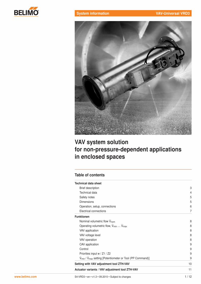
vav system solution for non-pressure-dependent ... · for non-pressure-dependent applications in...
TRANSCRIPT
www.belimo.com S4-VRD3 • en • v1.3 • 09.2010 • Subject to changes 1 / 12
System information VAV-Universal VRD3
VAV system solution for non-pressure-dependent applications in enclosed spaces
Table of contents
Technical data sheetBrief description 3Technical data 4Safety notes 5Dimensions 5Operation, setup, connections 6Electrical connections 7
FunktionenNominal volumetric flow nom 8Operating volumetric flow, min … max 8VAV application 8VAV voltage level 8VAV operation 8CAV application 9Control 9Priorities input w / Z1 / Z2 9min / max setting [Potentiometer or Tool (PP Command)] 9
Setting with VAV adjustment tool ZTH-VAV 10
Actuator variants / VAV adjustment tool ZTH-VAV 11


www.belimo.com S4-VRD3 • en • v1.3 • 09.2010 • Subject to changes 3 / 12
Plug-ready VAV-Universal system solution with integrated, almost static Belimo D3 pressure sensor for non-pressure-dependent VAV and CAV applications in enclosed spaces.Control: DC 2 … 10 V / 0 … 10 V / contactsSettings:• at the controller min / max or• with VAV adjustment tool ZTH-VAV
Brief description
Application The digital VAV-Universal solution VRD3 with its PI control characteristics is used for pressure-independent control of VAV units in the comfort zone.
Pressure measurement The integrated maintenance-free Belimo D3 differential pressure sensor allows a variety of applications ranging from offices, hospitals and hotels all the way to cruise ships.
Actuator The following actuator models are available, depending on the area of application, size and structural shape of the VAV unit:– Rotary actuator 0 … 95° , depending on the size 5, 10, 20 Nm– Rotary actuator 0 … 95° with safety position current-free CLOSED or OPEN, 4 or 20 Nm– Rotary actuator 0 … 1800° e.g. for iris dampers 3 Nm– Linear actuation 100, 200 or 300 mm linear motion, 150 N
Control function: VAV or CAV operation
Bus mode The utilisation of the VRD3 in MP-Bus systems (UK24LON, Fan Optimiser COU24-A-MP, etc.) is not possible. The VAV-Compact series and the VAV-Universal VRP-M system solution is available for these bus applications.
VAV – variable air volume For variable air volume applications based on a modulating reference variable, e.g. supplied by a room temperature controller or a DDC system; it facilitates demand-related, power-saving ventilation in individual rooms or in zones of air conditioning systems. The min ... max working range can be subdivided by selecting a mode. Available are the following: DC 2 … 10 / 0 … 10 V.
CAV – constant volume flow For constant air volume applications, e.g. in step mode, controlled by means of an occupancy switch. The following operating modes are available:CLOSED / min / max / OPEN
Function indication Functional readiness display with green LED.
Operating and service devices • VAV adjustment and diagnostics device ZTH-VAV: pluggable at the service socket of the VRD3 or at the PP interface (terminal 4).
• Belimo PC-Tool: cannot be used with the VRD3
Assembly and connection The connection is made by screw terminal. The actuator is connected with a plug-ready, pre-assembled cable.
OEM factory settings The VRD3 system solution is mounted on the VAV unit by the unit manufacturer, who adjusts and tests it according to the application. The VRD3 solution is sold exclusively through the OEM channel for this reason.
Technical data sheet VAV-Universal VRD3
. . . . . .

VRD3 Technical data sheet
4 / 12 S4-VRD3 • en • v1.3 • 09.2010 • Subject to changes www.belimo.com
Technical data
SupplyNominal voltage AC 24 V, 50 / 60 Hz / DC 24 VNominal voltage range AC 19.2 ... 28.8 V / DC 21.6 ... 28.8 VPower consumption 2 W / 3.5 VA, without actuator
Differential pressure sensor, installedType, principle of operation Belimo D3-Sensor, Dynamic with almost static behaviourOperating range For VRD3 application: 2 … 300 PaOverload capability ±3000 PaInstallation position Non-position-dependent, no zero-point compensation necessaryMaterials in contact with medium Glass, epoxy resin, PA, TPE
Control function: VAV and CAV unitsApplication – Single duct installations – Supply / exhaust air units
– Dual duct installations – Mixed unitsPressure range 2 … 300 Pa
Max. system primary pressure ≤1000 Pa>1000 ... 1500 Pa
Information for VAV unit manufacturer:∆P @ nom: useful adjusting range 50 ... 300 Pa∆P @ nom: useful adjusting range 150 ... 300 Pa
Characterising VAV units, OEM-independent, with linearization to match the differential pressure sensorMedium Supply and exhaust air in the comfort zone and in applications with sensor-compatible mediaMeasuring air conditions 0 … +50°C / 5 … 90% r.H., non-condensating
Operating volumetric flownom OEM-specific nominal volumetric flow setting, suitable for the VAV unitmax 30 … 100% of nom
min 0 … 100% of nom
VAV – input w, terminal 3 Switch-selectable VRD3 ↔ VRD2 (compatible with predecessor model, see page 4)Mode DC 2 … 10 V min … max, CLOSED with activation <0.1 V (see pg. 5 ... 7)Mode DC 0 … 10 V min … max
Input impedance ~100 kΩ
CAV – input w, terminal 3 – Compatible with L/N/SMV-D2M-MP– Operating stages CLOSED, min, max, OPEN
(see pg. 5 ... 7)
Override – input Z1 / Z2 Requires AC 24 V power supplyZ1 – terminal 6 OPENZ2 – terminal 7 CLOSED, min, max
Actual volumetric flow signal [U5] – terminal 5 – DC 2 … 10 / 0 … 10 V for 0 … 100% nom– Max. load 0.5 mA
Operatinglocal Potentiometer for min / max settingTool VAV adjustment tool ZTH-VAV, connection via service plug or PP connection
Actuator (..-V models)5 / 10 / 20 Nm, depending on applicationConnection can be plugged into VRD3
– Direction of rotation (l / r or ↑/↓)– Angle of rotation limitation or stroke limitation– Adaption, adjusting range modification and/or resolution to control range– Manual disengagement
(see pg. 10)
Sound power level – Max. 35 dB(A), SM24A-V max. 45 dB(A)– LF24-A-V Motor max. 35 dB(A), spring ≈ 62 dB(A), SF24A-V Motor max. 40 dB(A), spring ≈ 62 dB(A)
Damper rotation Clamp, for axle round / square or positive fit e.g. 8 x 8 mm
ConnectionSupply and control 7-pin screw terminals for 2 x 1.5 mm2
Tool connection RJ12 socketActuator 3-pin plug for ..-V actuator
SafetyProtection class III Safety extra-low voltageDegree of protection IP40EMC CE according to 2004/108/ECMode of operation Type 1 (EN 60730-1)Rated impulse voltage 0.8 kV (EN 60730-1)
. . . . . .
VRD3 Technical data sheet
www.belimo.com S4-VRD3 • en • v1.3 • 09.2010 • Subject to changes 5 / 12
Safety notes
!• The VRD3 system solution is not allowed to be used outside the specified field of
application, especially in aircraft or any other form of air transport.• Assembly must be carried out by trained personnel. Any legal regulations or regulations
issued by authorities must be observed during assembly.• The device does not contain any parts that can be replaced or repaired by the user.• The cable must not be removed from the actuator.• The device contains electrical and electronic components and is not allowed to be disposed
of as household refuse. All locally valid regulations and requirements must be observed.
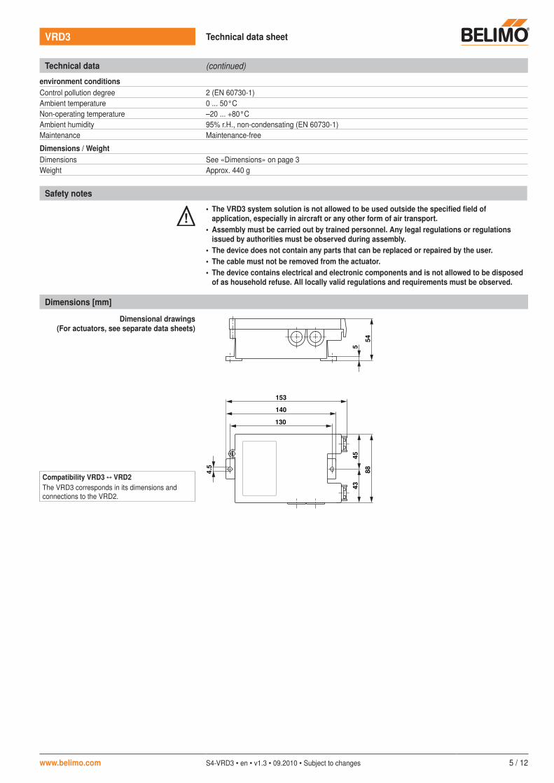
Dimensions [mm]
Dimensional drawings(For actuators, see separate data sheets)
4.5
130
140
153
45
43
88
5
54
Compatibility VRD3 ↔ VRD2The VRD3 corresponds in its dimensions and connections to the VRD2.
Technical data (continued)
environment conditionsControl pollution degree 2 (EN 60730-1)Ambient temperature 0 ... 50°CNon-operating temperature –20 ... +80°CAmbient humidity 95% r.H., non-condensating (EN 60730-1)Maintenance Maintenance-free
Dimensions / WeightDimensions See «Dimensions» on page 3Weight Approx. 440 g

VRD3 Technical data sheet
6 / 12 S4-VRD3 • en • v1.3 • 09.2010 • Subject to changes www.belimo.com
Operation, setup, connections
Setup, connections
VRD2VRD3
50/60Hz
24VAC/DC
2W
3.5VA
Power
Service
Actuator
PP U5 Z1 Z2w
1 2 3 4 5 6 7+~–T
min%nom
max%nom
Tool
Tool
III
a
b
Connecting terminals 1 … 7 Terminal Designation Function
1 / –Supply AC/DC 24 V
2 ~ / +
3 w Reference value input w jumper VRD3
VRD2
– Mode 0 … 10 / 2 … 10 V switchable with ZTH-VAV– Function as with new VAV-Compact L/N/SMV-D2-MP:
VAV: 0 … 10 / 2 … 10 V = min … maxCAV: CLOSED / min / max / OPEN
Reference value input w jumper
VRD3
VRD2
– Mode 0 … 10 / 2 … 10 V switchable with ZTH-VAV– Function as with VRD2:
VAV: 0 … 10 / 2 … 10 V = min … maxCAV: not possible use Z1 / Z2
4 PP PP interface for ZTH-VAV (no MP operation)
5 U5 Actual volumetric flow signal U5– Mode 0 … 10 / 2 … 10 V switchable with ZTH-VAV– Display range 0 … 100% nom
6 Z1 Override input Z1: Function OPEN
7 Z2 Forced control input Z2: function CLOSED / min / max
1 2
3
4
6
7
8
5
1 Operating volumetric flow settingmin 0 … 100% [in % of nom]
2 Operating volumetric flow settingmax 30 … 100% [in % of nom]
3 Tool connectiona System plug: internal Belimo function, not
for usersb Service: connection for VAV adjustment
tool ZTH-VAV
4 Jumper for input w (terminal 3)Function:– VRD2: VRD2-compatible– VRD3: VRD3 and L/N/SMV-D2-MP
5 Power LED, Function display 24 V
6 Connection for V-actuator
7 Connecting terminals 1 … 7
8 Connection D3 Sensor
Note– Supply via safety isolation transformer!– It is recommended that the PP connection
(terminal 4) and the 24 V be wired to readily accessible terminals in order to guarantee easy access with the VAV adjustment tool ZTH-VAV (e.t. at the room temperature controller CR24 or in the control cabinet).
The VRD3 does not support any MP operation!
!

VRD3 Technical data sheet
www.belimo.com S4-VRD3 • en • v1.3 • 09.2010 • Subject to changes 7 / 12
Electrical connections
Wiring diagrams Connection VRD3 VAV connection: supply and exhaust air system
CAV connection Connection Z1 / Z2 Connection input w
Overview control signals / FunctionsSignal terminal / Function Priority GND
pos. hydraulic switch
neg. hydraulic switch
24 VAC open
Forced input Z1 – terminal 6 1 – OPEN 1 – OPEN 1 –
Forced input Z2 – terminal 7 2 CLOSED 2 min 3 – max 4 –
Tool (PP-Cmd) → ZTH-VAV 3 CAV stages (Auto, CLOSED, OPEN, min, max, Stop)
Reference signal w – terminal 3 4 CLOSED 5 OPEN 6 CLOSED max 8 min 9Jumper: VRD3 Mode:
2 … 10 VMode: 0 … 10 V
AC 24 V
DC 24 V
~
~
T
T
4 3 2 1 VRD3
ZTH-VAV
PP w
T
5 6 7
U5 z1 z2
+
+
~ 4321 VRD3
ZTH-VAV
PPw
T
5 6 7
U5 z1 z2
+
~ 4321 VRD3
ZTH-VAV
PPw
T
5 6 7
U5 z1 z2
+
AC 24 V
DC 24 V
~T
T
+
AC 24 V
~ T
~ 4321 VRD3
ZTH-VAV
PPw
T
5 6 7
U5 z1 z2
+
AC 24 V~
~
T
4321 VRD3
ZTH-VAV
PPw
T
5 6 7
U5 z1 z2
+
Reference value input w
PP connection ZTH-VAV
Actual volumetric flow U5
Control input Z1 / Z2
Reference value input w 0…10 / 2…10 V e.g. of room temperature controller CR24
Actuator ..-VActuator ..-V
Actuator ..-V
a
b
a e.g. supply air unit
b e.g. exhaust air unit
c Parallel connection
d Master-Slave
c d
Compatibility VRD3 ↔ VRD2:– Reference signal [w] (terminal 3)
Plugging the jumper in at position «VRD2» causes the VRD3 to behave like the predecessor model VRD2 (i.e. no CAV control function via input w).
– Forced control inputs Z1 (terminal 6) and Z2 (terminal 7) are functionally compatible with the VRD2 and are not influenced by the jumper.
– Tool connection PP (terminal 4) The VRD3 is equipped with a separate tool connection PP (terminal 4). For the VRD2, the tool connection is made via terminal 5, which exhibits a combination function: volumetric flow actual value signal U5 and PP connection.
Note:The input signals 3 (w), 6 (Z1) and 7 (Z2) of several VRD3s can be switched with a joint signal, e.g. CLOSED.It is not permitted to switch connection 6 (Z1) with a VRD2 terminal 6.
Note:*) CAV control applications requires AC 24 V
power supply.
CLOSED
min *)
max
OPEN
CLOSED
min
OPEN *)
max1
2
3
4
7
9
8
6
Actuator ..-V Actuator ..-V
5
*)
PP
PP
PPVRD3
VRD2
Jumper
8 / 12 S4-VRD3 • en • v1.3 • 09.2010 • Subject to changes www.belimo.com
Functions
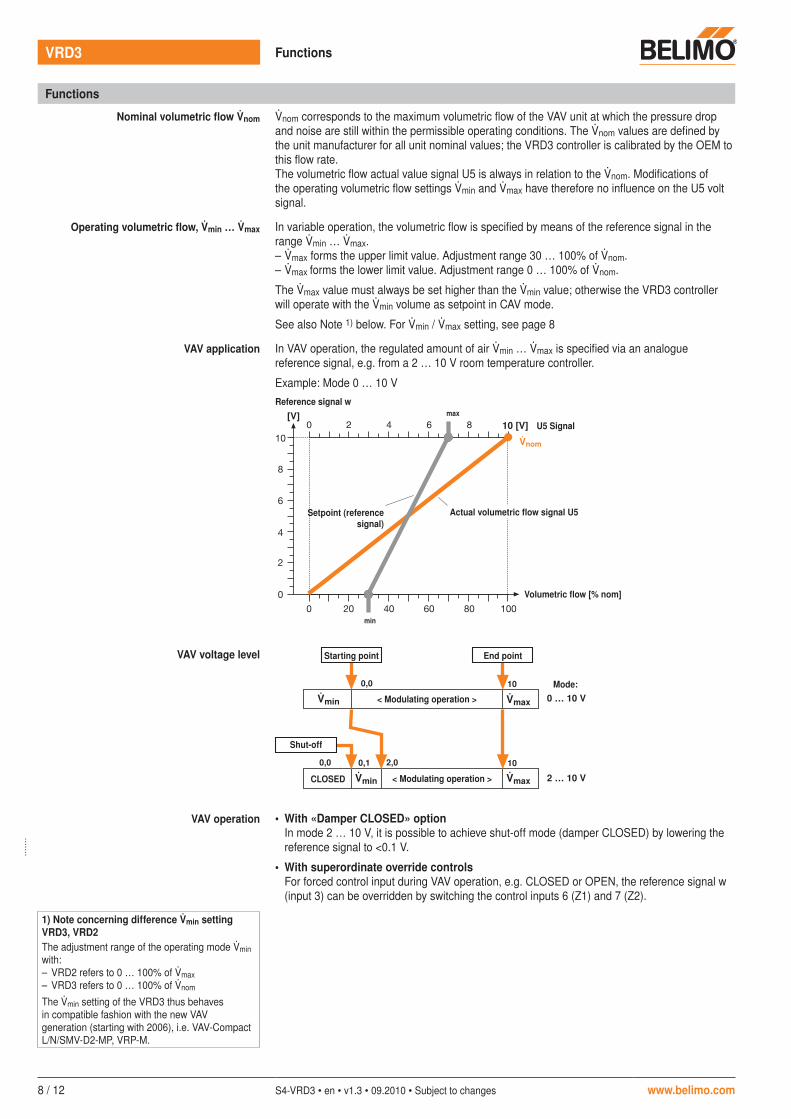
Nominal volumetric flow nom nom corresponds to the maximum volumetric flow of the VAV unit at which the pressure drop and noise are still within the permissible operating conditions. The nom values are defined by the unit manufacturer for all unit nominal values; the VRD3 controller is calibrated by the OEM to this flow rate.The volumetric flow actual value signal U5 is always in relation to the nom. Modifications of the operating volumetric flow settings min and max have therefore no influence on the U5 volt signal.
Operating volumetric flow, min … max In variable operation, the volumetric flow is specified by means of the reference signal in the range min … max.– max forms the upper limit value. Adjustment range 30 … 100% of nom.– max forms the lower limit value. Adjustment range 0 … 100% of nom.
The max value must always be set higher than the min value; otherwise the VRD3 controller will operate with the min volume as setpoint in CAV mode.
See also Note 1) below. For min / max setting, see page 8
VAV application In VAV operation, the regulated amount of air min … max is specified via an analogue reference signal, e.g. from a 2 … 10 V room temperature controller.
Example: Mode 0 … 10 V
VAV voltage level
VAV operation • With «Damper CLOSED» optionIn mode 2 … 10 V, it is possible to achieve shut-off mode (damper CLOSED) by lowering the reference signal to <0.1 V.
• With superordinate override controlsFor forced control input during VAV operation, e.g. CLOSED or OPEN, the reference signal w (input 3) can be overridden by switching the control inputs 6 (Z1) and 7 (Z2).
10 [V]
nom
[V] max
min
Volumetric flow [% nom]
0,0 10
0,0 0,1 102,0
0 … 10 V
2 … 10 V
min
min max
max
Starting point End point
Shut-off
CLOSED
< Modulating operation >
< Modulating operation >
Mode:
Reference signal w
Actual volumetric flow signal U5Setpoint (reference signal)
U5 Signal
1) Note concerning difference min setting VRD3, VRD2The adjustment range of the operating mode min with:– VRD2 refers to 0 … 100% of max– VRD3 refers to 0 … 100% of nom
The min setting of the VRD3 thus behaves in compatible fashion with the new VAV generation (starting with 2006), i.e. VAV-Compact L/N/SMV-D2-MP, VRP-M.
VRD3 Functions
. . . . . . .

www.belimo.com S4-VRD3 • en • v1.3 • 09.2010 • Subject to changes 9 / 12
Functions (continued)
CAV application Four constant volumetric flow (CAV) stages are available for step mode:– Shut-off operation – damper CLOSED: the damper is moved to CLOSED.– CAV stages min / max: the VRD3 controls the selected volumetric flow at a fixed value.– Flushing operation – damper OPEN: The damper can be opened for maximum ventilation, in
which case air volume control is deactivated.The operating mode control signals are connected to inputs 6 (Z1) and 7 (Z2). If signals appear at these two inputs simultaneously, input 6 (Z1) for the OPEN function takes priority.
Control10 [V]
nom
max
min
Priorities input w / Z1 / Z2 Prio 1: Z1 (terminal 6)
Prio 2: Z2 (terminal 7)
Prio 3: VAV adjustment tool ZTH-VAV (PP command)
Prio 4: Reference signal w (terminal 3)
Volumetric flow [% nom]
– OPEN– max
Actual volumetric flow signal U5
OPEN
CLOSED
U5 Signal
– min– CLOSED
min / max setting [Potentiometer or Tool (PP Command)]
Die operating volumetric flow settings min and max can be adjusted two different ways on the VRD3:a) directly on the adjustment potentiometer (analogous to the VRD2)
min 0 … 100% of nommax 30 … 100% of nom
b) with VAV adjustment tool ZTH-VAV (PP command)
Both of the potentiometers min und max must be set to Tool position in order to write a value – with PP Command – in the VRD3. If the potentiometer(s) are set to «Tool» with connected ZTH-VAV, then the menu will need to be refreshed under certain circumstances by actuating the keys ↑↓. For function, see following illustration:
The max value must always be set higher than the min value; otherwise the VRD3 controller will operate with the min volume as setpoint in CAV mode.
ZTH-VAV
– + OK0
10
20
3040 50
60
70
80
90
100 ZTH-VAV
45 %
45 %
VRD3
Adjustment potentiometer min / max
Potentiometer:– Tool: ZTH value– 0 … 100%: Potentiometer value active
effective value
0 … 100% Tool (PP)
Tool
parameterised value
Automatic adjustment via potentiometer position
w = write
Tool
r wr = read
Note concerning difference min setting VRD3, VRD2The adjustment range of the operating mode min with:– VRD2 refers to 0 … 100% of max– VRD3 refers to 0 … 100% of nom
The min setting of the VRD3 thus behaves in compatible fashion with the new VAV generation (starting with 2006), i.e. VAV-Compact L/N/SMV-D2-MP, VRP-M.
VRD3 Functions
10 / 12 S4-VRD3 • en • v1.3 • 09.2010 • Subject to changes www.belimo.com
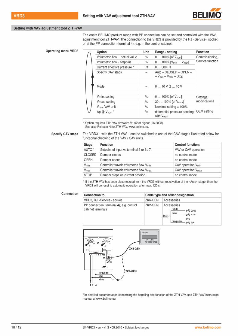
Setting with VAV adjustment tool ZTH-VAV
The entire BELIMO product range with PP connection can be set and controlled with the VAV adjustment tool ZTH-VAV. The connection to the VRD3 is provided by the RJ «Service» socket or at the PP connection (terminal 4), e.g. in the control cabinet.
Operating menu VRD3 Option Unit Range / setting FunctionVolumetric flow – actual value % 0 … 100% [of nom] Commissioning,
Service functionVolumetric flow - setpoint % 0 … 100% [min … max]Current effective pressure * Pa 0 … 300 PaSpecify CAV steps – Auto – CLOSED – OPEN –
– min – max – Stop
Mode – 0 … 10 V, 2 … 10 V
min. setting % 0 … 100% [of nom] Settings, modificationsmax. setting % 30 … 100% [of nom]
nom VAV unit % Nominal setting = 100%OEM setting∆p @ nom * Pa differential pressure pending
with nom
* Option requires ZTH-VAV firmware V1.02 or higher (06.2008). See also Release Note ZTH-VAV, www.belimo.eu.
Specify CAV steps The VRD3 – with the ZTH-VAV – can be switched to one of the CAV stages illustrated below for functional checking of the VAV / CAV units.
Stage Function Control function:AUTO * Setpoint of input w, terminal 3 or 6 / 7. VAV or CAV operationCLOSED Damper closes no control modeOPEN Damper opens no control modemin Controller travels volumetric flow min CAV operation min
max Controller travels volumetric flow max CAV operation max
STOP Damper stops on current position no control mode
* If the ZTH-VAV has been disconnected from the VRD3 without reactivation of the «Auto» stage, then the VRD3 will be reset to automatic operation after max. 120 s.
Connection Connection to Cable type and order designationVRD3, RJ «Service» socket ZK6-GEN AccessoriesPP connection (terminal 4), e.g. control cabinet terminals
ZK2-GEN Accessorieswhite
blue
turquoise
1
2
3
4
GND
~ / +
PP
ZTH-VAV
– + OK
1 42
VRD2VRD3
Power
Se
rv
ice
Actuator
min
%nom
max
%nom
Tool
Tool
ZK6-GEN
ZK2-GEN
whiteblueturquoise
For detailed documentation concerning the handling and function of the ZTH-VAV, see ZTH-VAV instruction manual at www.belimo.eu
VRD3 Setting with VAV adjustment tool ZTH-VAV

www.belimo.com S4-VRD3 • en • v1.3 • 09.2010 • Subject to changes 11 / 12
Actuator variants (standard actuators)
Type Actuator Features
Rotary actuators 0 … 90° LM24A-V – Damper actuator for VAV-Universal– AC/DC 24 V, modulating, 5 Nm– Control DC 6.0 ±4 V from VRD3 controller– Motor running time 110 ... 150 s– Connection: cable with plug– Angle of rotation 90°– For dimensions see data sheet LM24A-MF
NM24A-V – Damper actuator for VAV-Universal– AC/DC 24 V, modulating, 10 Nm– Control DC 6.0 ±4 V from VRD3 controller– Motor running time 120 s– Connection: cable with plug– Angle of rotation 90°– For dimensions see data sheet NM24A-MF
SM24A-V – Damper actuator for VAV-Universal– AC/DC 24 V, modulating, 20 Nm– Control DC 6.0 ±4 V from VRD3 controller– Motor running time 120 s– Connection: cable with plug– Angle of rotation 90°– For dimensions see data sheet SM24A-MF
Spring-return actuators 0 … 90° LF24-V – Spring-return actuator for VAV-Universal– AC/DC 24 V, modulating, 4 Nm– Control DC 6.0 ±4 V from VRD3 controller– Running time motor 120...300 s– Running time spring-return approximately 20 s– Connection: cable with plug– Angle of rotation 95°– For dimensions see data sheet LF24
SF24A-V – Spring-return actuator for VAV-Universal– AC/DC 24 V, modulating, 20 Nm– Control DC 6.0 ±4 V from VRD3 controller– Running time motor 150 s– Running time spring-return approximately 20 s– Connection: cable with plug– Angle of rotation 95°– For dimensions see data sheet SF24A
Actuators* for special applications * LU24A-.. – Rotary actuator 0 … 1800° rotating, e.g. for iris dampers 3 Nm
– For dimensions see data sheet LU24A-MF
* on request
* LH24A-.. – Linear actuation 100, 200 oder 300 mm linear motion, 150 Nm
– For dimensions see data sheet LH24A-MF..
VAV adjustment tool ZTH-VAV
ZTH-VAV – Adjustment tool for Belimo VAV controller– Supply to VAV controller AC/DC 24 V
For more detailed documents, see www.belimo.eu
VRD3 Actuator variants / VAV adjustment tool ZTH-VAV
. . . . . . . . . . . . . . . . . . . . . . . . . . . . . . . . . . . . . . . .

All inclusive.
Belimo worldwide: www.belimo.com
Headquarters Subsidiaries, Representatives and Agencies
BELIMO Holding AGBrunnenbachstrasse 1CH-8340 HinwilTel. +41 (0)43 843 61 11Fax +41 (0)43 843 62 [email protected]
AgentinaAustraliaBahrainBelgiumBosnia-HerzegovinaBrazilBulgariaCanadaChileCroatiaCyprusCzech Republic
DenmarkEgyptEstoniaFinlandFranceGreat BritainGermanyGreeceHong KongHungaryIcelandIndiaIndonesiaIrelandIsraelItalyJapanJordanKuwaitLatvia
LebanonLiechtensteinLithuaniaLuxembourgMalaysiaMexicoMoroccoNetherlandsNew ZealandNorwayOmanPakistanPeople’s Republic of ChinaPhilippinesPolandPortugalQatarRepublic of Korea (South Korea)
RumaniaRussiaSaudi ArabiaSingaporeSlovakiaSloveniaSouth AfricaSpainSwedenSwitzerlandTaiwanTurkeyUkraineUnited Arab EmiratesUnited States of America
5 years Guarantee
Worldwide present
Complete assortment from a single source
Examined Quality
Short delivery time
Comprehensive support