varian multi-gauge controller - ideal vac price of the product. items expendable in normal use are...
TRANSCRIPT

DR
AF
T 2
/6/0
4
������������� ���
Multi-Gauge Controller
Document No. 699908091Revision XDecember 2003
INSTRUCTION MANUAL

DR
AF
T 2
/6/0
4
Multi-Gauge Controller
Convectron® is a registered trademark of the Granville–Phillips Co.
Copyright 2003Vacuum Technologies

Multi-Gauge Controller
DR
AF
T 2
/6/0
4
Warranty
Products manufactured by Seller are warranted against defects in materials and workmanship for twelve (12) months from date of shipment thereof to Customer, and Seller’s liability under valid warranty claims is limited, at the option of Seller, to repair, replacement, or refund of an equitable portion of the purchase price of the Product. Items expendable in normal use are not covered by this warranty. All warranty replacement or repair of parts shall be limited to equipment malfunctions which, in the sole opinion of Seller, are due or traceable to defects in original materials or workmanship. All obligations of Seller under this warranty shall cease in the event of abuse, accident, alteration, misuse, or neglect of the equipment. In-warranty repaired or replacement parts are warranted only for the remaining unex-pired portion of the original warranty period applicable to the repaired or replaced parts. After expira-tion of the applicable warranty period, Customer shall be charged at the then current prices for parts, labor, and transportation.Reasonable care must be used to avoid hazards. Seller expressly disclaims responsibility for loss or damage caused by use of its Products other than in accordance with proper operating procedures.When products are used with toxic chemicals, or in an atmosphere that is dangerous to the health of humans, or is environmentally unsafe, it will be the responsibility of the Customer to have the product cleaned by an independent agency skilled and approved in handling and cleaning contaminated mate-rials before the product will be accepted by Vacuum Technologies, Inc. for repair and/or replacement.Except as stated herein, Seller makes no warranty, express or implied (either in fact or by operation of law), statutory or otherwise; and, except as stated herein, Seller shall have no liability under any war-ranty, express or implied (either in fact or by operation of law), statutory or otherwise. Statements made by any person, including representatives of Seller, which are inconsistent or in conflict with the terms of this warranty shall not be binding upon Seller unless reduced to writing and approved by an officer of Seller.
Warranty Replacement and AdjustmentAll claims under warranty must be made promptly after occurrence of circumstances giving rise thereto, and must be received within the applicable warranty period by Seller or its authorized representative. Such claims should include the Product serial number, the date of shipment, and a full description of the circumstances giving rise to the claim. Before any Products are returned for repair and/or adjust-ment, written authorization from Seller or its authorized representative for the return and instructions as to how and where these Products should be returned must be obtained. Any Product returned to Seller for examination shall be prepaid via the means of transportation indicated as acceptable by Seller. Seller reserves the right to reject any warranty claim not promptly reported and any warranty claim on any item that has been altered or has been returned by non-acceptable means of transportation. When any Product is returned for examination and inspection, or for any other reason, Customer shall be responsible for all damage resulting from improper packing or handling, and for loss in transit, notwith-standing any defect or non-conformity in the Product, in all cases, Seller has the sole responsibility for determining the cause and nature of failure, and Seller's determination with regard thereto shall be final.If it is found that Seller’s Product has been returned without cause and is still serviceable, Customer will be notified and the Product returned at its expense; in addition, a charge for testing and examination may be made on Products so returned.8/15/95
iii

Multi-Gauge Controller D
RA
FT
2/6
/04
This page intentionally left blank.

Multi-Gauge Controller
DR
AF
T 2
/6/0
4
Contents
Declaration of Conformity ................................................................................................................ xiiiPreface ..............................................................................................................................................xv
Manual Overview ........................................................................................................................xvDocument Conventions ...............................................................................................................xvCleaning ......................................................................................................................................xvMulti-Gauge Hazards .................................................................................................................xvi
Grounding the Multi-Gauge Controller ..................................................................................xviEMC Warnings ..................................................................................................................... xviiInstallation Requirements..................................................................................................... xvii
Contacting Vacuum Technologies ........................................................................................... xviii
Section 1. Introduction and Installation ........................................................................................... 1-11.1 Introduction ......................................................................................................................... 1-1
1.1.1 Optional PCBs............................................................................................................. 1-11.1.2 Communications Options ............................................................................................ 1-2
1.1.2.1 RS232 Option ................................................................................................. 1-21.1.2.2 RS485/422 Option .......................................................................................... 1-2
1.1.3 Battery Backup............................................................................................................ 1-31.1.4 Front Panel.................................................................................................................. 1-3
1.1.4.3 Keyboard ........................................................................................................ 1-41.2 Installation............................................................................................................................ 1-6
1.2.1 Unpacking ................................................................................................................... 1-61.2.2 Setting Line Voltage and Installing Optional PCBs ..................................................... 1-7
Section 2. Operating Instructions .................................................................................................... 2-12.1 Setting Parameters ............................................................................................................. 2-12.2 Operating the Multi-Gauge................................................................................................... 2-2
2.2.1 Access Codes ............................................................................................................. 2-3
Section 3. Troubleshooting ............................................................................................................. 3-13.1 Keyboard Commands ......................................................................................................... 3-13.2 Error Codes.......................................................................................................................... 3-13.3 Changing Line Fuses ........................................................................................................... 3-33.4 Changing the PROM............................................................................................................ 3-3
Appendix A. Gas Correction Factor Table ......................................................................................A-1
Appendix B. UHV Board .................................................................................................................B-1B.1 Specifications ......................................................................................................................B-1B.2 Installation ...........................................................................................................................B-3B.3 Calibration and Adjustments................................................................................................B-4B.4 UHV Control Card Operation...............................................................................................B-4B.5 Recorder Output ..................................................................................................................B-6
v

Multi-Gauge Controller D
RA
FT
2/6
/04
Appendix C. Thermocouple Board ..................................................................................................C-1C.1 Thermocouple Principles of Operation ................................................................................C-1C.2 Specifications ......................................................................................................................C-2C.3 Installation ...........................................................................................................................C-3C.4 Operation.............................................................................................................................C-4C.5 Calibration ...........................................................................................................................C-4C.6 Auto Turn-On.......................................................................................................................C-5C.7 Recorder Output..................................................................................................................C-6
Appendix D. Bayard-Alpert Board ...................................................................................................D-1D.1 Specifications ......................................................................................................................D-1D.2 Installation ...........................................................................................................................D-3D.3 Calibration and Adjustments ...............................................................................................D-5D.4 Bayard/Alpert Control Card Operation ................................................................................D-5D.5 Recorder Output..................................................................................................................D-7
Appendix E. Cold Cathode Board ...................................................................................................E-1E.1 Theory of Operation.............................................................................................................E-2E.2 Specifications ......................................................................................................................E-3E.3 Installation ...........................................................................................................................E-4E.4 Calibration and Adjustments................................................................................................E-5E.5 Cold Cathode Board Operation ...........................................................................................E-5
E.5.1 Operation At High Pressure .......................................................................................E-6E.5.2 Starting At Low Pressure ...........................................................................................E-6E.5.3 Gauge Tube Maintenance .........................................................................................E-7E.5.4 Troubleshooting .........................................................................................................E-8
E.6 Recorder Output ..................................................................................................................E-9
Appendix F. Remote I/O Board .......................................................................................................F-1F.1 Specifications.......................................................................................................................F-1F.2 Installation............................................................................................................................F-2F.3 Operation .............................................................................................................................F-4
F.3.1 Inputs .........................................................................................................................F-4F.3.2 Outputs ......................................................................................................................F-4
Appendix G. Set Point Board ......................................................................................................... G-1G.1 Specifications ..................................................................................................................... G-1G.2 Installation .......................................................................................................................... G-2
G.2.1 Installation � Female ................................................................................................ G-2G.2.2 Installation � Male .................................................................................................... G-3
G.3 Operation � Programming Setpoints.................................................................................. G-4
Appendix H. Capacitance Diaphragm Gauge Board ......................................................................H-1H.1 Theory of Operation ............................................................................................................H-1H.2 Specifications ......................................................................................................................H-2H.3 Operation.............................................................................................................................H-4
H.3.1 Zero Procedure .........................................................................................................H-5
vi
Multi-Gauge Controller
DR
AF
T 2
/6/0
4
Appendix I. Convectron Board ......................................................................................................... I-1I.1 Convectron Principles of Operation ....................................................................................... I-1I.2 Specifications......................................................................................................................... I-2I.3 Installation.............................................................................................................................. I-2I.4 Operation ............................................................................................................................... I-4
I.4.1 Calibration .................................................................................................................... I-4I.4.2 Auto Turn-on ................................................................................................................ I-5
Appendix J. Inverted Magnetron Board .......................................................................................... J-1J.1 Theory of Operation ............................................................................................................. J-2J.1 Specifications ....................................................................................................................... J-3J.2 Installation ............................................................................................................................ J-4J.3 Calibration and Adjustments ................................................................................................ J-5J.4 Inverted Magnetron Board Operation................................................................................... J-5
J.4.1 Operation at High Pressure ........................................................................................ J-6J.4.2 Starting at Low Pressure ............................................................................................ J-6J.4.3 Gauge Tube Maintenance .......................................................................................... J-7J.4.4 Troubleshooting .......................................................................................................... J-7
J.5 Recorder Output................................................................................................................... J-8
Appendix K. ConvecTorr Board ......................................................................................................K-1K.1 Principle of Operation ..........................................................................................................K-1
K.1.1 Traditional Thermocouple Theory ..............................................................................K-1K.1.2 The ConvecTorr .........................................................................................................K-2
K.2 Specifications ......................................................................................................................K-2K.3 Operation.............................................................................................................................K-3K.4 Calibration ...........................................................................................................................K-3K.5 Auto Turn-on........................................................................................................................K-4K.6 Recorder Output ..................................................................................................................K-5
Appendix L. RS232 and RS485/422 Boards, and ASCII Protocol Option ...................................... L-1L.1 RS232 .................................................................................................................................. L-1
L.1.1 Specifications ............................................................................................................. L-2L.1.2 RS232 Installation ...................................................................................................... L-3
L.1.2.1 Fiber Optic Board Option................................................................................. L-5L.2 RS485 Description ............................................................................................................... L-5
L.2.3 RS485 Installation ...................................................................................................... L-6L.2.3.2 ASCII Protocol................................................................................................. L-9
L.2.3.2.1 Command/Response Format ........................................................L-10L.2.3.2.1.1 Command Set .............................................................. L-10
L.2.3.3 Testing, Troubleshooting, and Debugging Multi-Gauge Serial Communication Issues .............................................................................................. L-14
L.2.3.3.1 Tips � RS232.................................................................................. L-14L.2.3.3.2 Tips � RS422/485 ..........................................................................L-14L.2.3.3.3 Terminal-Windows .........................................................................L-15
Appendix M. Multi-Gauge Specifications ....................................................................................... M-1M.3 Specifications.....................................................................................................................M-1
vii

Multi-Gauge Controller D
RA
FT
2/6
/04
This page intentionally left blank.

Multi-Gauge Controller
DR
AF
T 2
/6/0
4
Figures
Figure Title Page1-1 Multi-Gauge Front Panel with Fully Lit (Will take new picture)............................................ 1-31-2 Setting Line Voltage............................................................................................................ 1-71-3 Installing the Option Boards................................................................................................ 1-83-1 Straightening the Pins......................................................................................................... 3-43-2 Location of Chip and Socket Notches................................................................................. 3-43-3 Installing the Chip ............................................................................................................... 3-5B-1 UHV Card Connections.......................................................................................................B-3B-2 Assembling the Cable/Plug.................................................................................................B-6B-3 Recorder Output Characteristics.........................................................................................B-7C-1 37-Pin Connector ............................................................................................................... C-3C-2 Response vs. Pressure Curves ......................................................................................... C-6D-1 Bayard Alpert Card Connections ....................................................................................... D-3D-2 Jumper Positions ............................................................................................................... D-4D-3 Assembling the Cable/Plug................................................................................................ D-7D-4 Recorder Output Characteristics........................................................................................ D-7E-1 Figure 2. Cross-Section Drawing of Cold Cathode Gauge .................................................E-2E-2 Card Connections ...............................................................................................................E-4E-3 Assembling the Cable/Plug.................................................................................................E-9E-4 Recorder Output Characteristics.......................................................................................E-10F-1 Pin Connector .....................................................................................................................F-3G-1 Female Connector Front View ........................................................................................... G-2G-2 Male Connector Front View ............................................................................................... G-3I-1 Mounting the Convectron Tube............................................................................................ I-2I-2 37 Pin Connector ................................................................................................................. I-3I-3 Granville Phillips/275 Convectron with Multi-Gauge Recorder Output ................................ I-6J-1 Card Connections ............................................................................................................... J-4J-2 Figure 2. Assembling the Recorder Output Cable/Plug ...................................................... J-8J-3 Figure 3. Recorder Output Characteristics ......................................................................... J-9K-1 Multi-Gauge Convectorr Recorder Output ..........................................................................K-5L-1 Cable Installation ................................................................................................................ L-3L-2 Installing the Fiber Optic Board........................................................................................... L-4L-3 RS485 Installation............................................................................................................... L-7L-4 RS485 Connector ............................................................................................................... L-8
ix

Multi-Gauge Controller D
RA
FT
2/6
/04
This page intentionally left blank.

Multi-Gauge Controller
DR
AF
T 2
/6/0
4
Tables
Table Title Page2-1 Functions and Access Codes ............................................................................................ 2-3A-1 Gas Correction Factor Table ..............................................................................................A-2B-1 UHV Board Specifications ..................................................................................................B-1B-2 Cable Lengths and Sizes ...................................................................................................B-3C-1 Thermocouple Board Specifications ................................................................................. C-2C-2 Signal and Pin Assignments ............................................................................................. C-3D-1 Bayard-Alpert Board Specifications .................................................................................. D-1D-2 Cable Lengths and Sizes .................................................................................................. D-3E-1 Cold Cathode Board Specifications ...................................................................................E-3E-2 Model 524 Replacement Kit ...............................................................................................E-7E-3 Cold Cathode Troubleshooting ..........................................................................................E-8F-1 Remote I/O Board Specifications .......................................................................................F-1F-2 Input Function vs. Pin Number ...........................................................................................F-2F-3 Output Function vs. Pin Number ........................................................................................F-3G-1 Setpoint vs. Terminal Connections ................................................................................... G-2G-2 Setpoint vs. Terminal Connections ................................................................................... G-3G-3 Setpoint and Hysteresis Suggested Values ...................................................................... G-5H-1 Specifications Capacitance Diaphragm Board .................................................................. H-2H-2 Vacuum Technologies Transducer Recommended Values .............................................. H-5I-1 Specifications Convectron Board ........................................................................................ I-2I-2 Signal and Pin Assignments ............................................................................................... I-3I-3 Cable Lengths ..................................................................................................................... I-3J-1 Inverted Magnetron Board Specifications .......................................................................... J-3J-2 Inverted Magnetron Troubleshooting ................................................................................. J-7K-1 ConvecTorr Board Specifications ......................................................................................K-2K-2 Recorder Output Connections ...........................................................................................K-5L-1 Connection Configurations ................................................................................................. L-1L-2 Mother Board Revisions ..................................................................................................... L-1L-3 RS232 Driver Board Multi-Gauge Port Signal Specifications ............................................ L-2L-4 Fiber Optic Board Installation Specifications ..................................................................... L-5L-5 RS422/RS485 DIP Switch Settings ................................................................................... L-6L-6 Terminating Resistance Settings ....................................................................................... L-6L-7 Board Revision Settings ..................................................................................................... L-6L-8 DIN Connector Signal and Pin Assignments ..................................................................... L-8L-9 Command Set ................................................................................................................. L-11M-1 Multi-Gauge Specifications ...............................................................................................M-1
xi

Multi-Gauge Controller D
RA
FT
2/6
/04
This page intentionally left blank.

Varian, Inc.
declare under our sole responsibility that the product,erklären, in alleniniger Verantwortung, daß dieses Produkt,déclarons sous notre seule responsabilité que le produit,declaramos, bajo nuestra sola responsabilidad, que el producto,verklaren onder onze verantwoordelijkheid, dat het product,dichiariamo sotto nostra unica responsabilità, che il prodotto,
Declaration of ConformityKonformitätserklärungDéclaration de ConformitéDeclaración de ConformidadVerklaring de OvereenstemmingDichiarazione di Conformità
WeWirNousNosotrosWijNoi
Lexington, MA, 02421-3133 USA 121 Hartwell AvenueVacuum Technologies
Multi-Gauge Controller
to which this declaration relates is in conformity with the following standard(s) or other normative documents.auf das sich diese Erklärung bezieht, mit der/den flogenden Norm(en) oder Richtlinie(n) übereinstimmt.auquel se réfère cette déclaration est conforme à la (auz) norme(s) ou au(x) document(s) normatif(s).al que se refiere esta declaración es conforme a la(s) norma(s) u otro(s) documento(s) normativo(s).waamaar deze verklaring verwijst, aan de volende norm(en) of richtlijn(en) beantwoodt.a cui se rifersce questa dichiarazione è conforme alla/e sequente/I norma/o documento/I normativo/i.
EN 550111991 . . . . . . . . . . . . . . . . . . . . . . . . Group 1 Class A ISM emission requirements
EN 61010-11993 . . . . . . . . . . . . . . . . . . . . . . . . Safety requirements for electrical equipment for measurement, control, and
laboratory use incorporating Amendments Nos 1 and 2.EN 50082-2
1995 . . . . . . . . . . . . . . . . . . . . . . . . EMC heavy industrial generic immunity standard
Frederick C. CampbellOperations ManagerVacuum Technologies
Lexington, Massachusetts, USAVarian, Inc.
October 2003
Declaration of Conformity

Multi-Gauge Controller
This page intentionally left blank.
DR
AF
T 2
/6/0
4

Multi-Gauge Controller
DR
AF
T 2
/6/0
4
Preface
Manual OverviewThis manual explains the operation, configuration and troubleshooting for the Multi-Gauge Basic Unit. It also explains, in a series of appendixes, the various boards that can be used to tailor the units’ functionality.
Document ConventionsThe following format is used in this manual to call attention to hazards.
WARNING Warnings are used when failure to observe instructions or precautions could result in injury or death.
CAUTION Cautions are used when failure to observe instructions could result in damage to equipment, whether Vacuum Technologies supplied or other associated equipment.
NOTE Notes contain information to aid the operator in obtaining the best performance from the equipment.
Cleaning
NOTE Clean the unit with a slightly damp clean soft cloth. Do not use any solvents on the cloth or the unit.
xv

Multi-Gauge Controller D
RA
FT
2/6
/04
Multi-Gauge HazardsThis product must only be operated and maintained by trained personnel.
Before operating or servicing equipment, read and thoroughly understand all operation/maintenance manuals provided by Vacuum Technologies. Be aware of the hazards associated with this equipment, know how to recognize potentially hazardous conditions, and how to avoid them. Read carefully and strictly observe all cautions and warnings. The consequences of unskilled, improper, or careless operation of the equipment can be serious.
In addition, consult local, state, and national agencies regarding specific requirements and regulations. Address any safety, operation, and/or maintenance questions to your nearest Vacuum Technologies office.
Grounding the Multi-Gauge Controller
Be certain that your Multi-Gauge Ion Gauge Controller and vacuum system are separately grounded to a common ground.
WARNING ❑ Do not place a ground wire between the vacuum chamber and the controller chassis; large continuous currents could flow through it.
❑ Personnel can be killed by high voltages (160 to 900 V may be present in an improperly grounded system).
❑ Make absolutely sure that your vacuum system is grounded as shown in Figure 1.
❑ Test the system ground to be sure that it is complete and capable of supporting at least 10 A.
Figure 1 Ion Gauge and Vacuum System Connections
Ion Gauge Controller Vacuum System
Power DistributionBreaker Box
Power Common or Safety Ground Lead
Do not make direct chassis tovacuum system Connection!
Note: are not shown.Other power leads
xvi

Multi-Gauge Controller
DR
AF
T 2
/6/0
4
EMC Warnings
An independent agency has determined that all vacuum chambers, regardless of manufacture, can become charged to lethal voltage levels, under certain conditions, if they are not grounded with a quality, common ground with their ionization tube controller. After each maintenance/service procedure and before operating the controller and vacuum system, verify the integrity of the ground of both units. Failure to do so could cost you your life.
WARNING This equipment contains voltages up to 3000 V, high enough to cause death or serious injury. Equipment should be designed to prevent personal contact with high voltages.
Always break the primary circuit when direct access to the control unit is required
CAUTION This equipment has been tested and found to comply with the limits for a Class A digital device, pursuant to Part 15 of the FCC rules. These limits are designed to provide reasonable protection against harmful interference when the equipment is operated in a commercial environment. This equipment generates, uses, and can radiate radio frequency energy and, if not installed and used in accordance with the instruction manual, can cause harmful interference to radio communica-tions. Operation of this equipment in a residential area is also likely to cause harmful radio communications interference, in which case, the user is required to correct the interference at his own expense.
Installation Requirements
To maintain compliance with both the FCC Part 15 rules and the European Union’s EMI directives, use a shielded cable constructed of a braided shield and metal or metalized plastic backshells directly connected to the cable shield at the 15 position D-Sub connector of the unit. Connect the shield to ground at the user’s equipment. Failure to install the equipment in this way can result in the unit no longer meeting the requirements for radiated emissions and susceptibility.
xvii

Multi-Gauge Controller D
RA
FT
2/6
/04
Contacting Vacuum TechnologiesIn the United States, you can contact Vacuum Technologies Customer Service at 1-800-8VARIAN.
Internet users:
❑ Send email to Customer Service & Technical Support at [email protected]
❑ Visit our web site at www.varianinc.com/vacuum
❑ Order on line at www.evarian.com
See the back cover of this manual for a listing of our sales and service offices.
xviii

Multi-Gauge Controller
DR
AF
T 2
/6/0
4
Section 1. Introduction and Installation
Vacuum Technologies Multi-Gauge is a half-rack, modular vacuum gauge controller offering unprecedented flexibility. Multi-Gauge operates up to three ion gauges and eight thermocouple gauges simultaneously or adds process control options such as setpoints or Remote I/O options by using fewer gauge boards.
1.1 IntroductionThis section introduces the Multi-Gauge:
❑ Section 1.1.1 “Optional PCBs” on page 1-1
❑ Section 1.1.2 “Communications Options” on page 1-2
❑ Section 1.1.3 “Battery Backup” on page 1-3
❑ Section 1.1.4 “Front Panel” on page 1-3
1.1.1 Optional PCBs
The mother board can host up to five optional PCBs, with the following restrictions:
❑ Up to three high-profile boards, consisting of:
❑ Bayard/Alpert (Appendix D)
❑ UHV (Appendix B)
❑ Inverted Magnetron (Appendix J)
❑ Cold Cathode (Appendix E)
❑ Capacitance Diaphragm (Appendix H) boards with a limit of two Capacitance Diaphragm boards (each board runs two heads)
❑ Up to two Thermocouple (Appendix C) boards
❑ Two ConvecTorr (Appendix K) boards (two ConvecTorr gauges/board, total 4 maximum)
❑ One Setpoint (Appendix G) board
❑ One Remote I/O (Appendix F) board
❑ Other boards as they become available
1-1

Multi-Gauge Controller D
RA
FT
2/6
/04
1.1.2 Communications Options
The communications slot is a devoted, stand-alone location and neither of the communications interfaces use the five card slot locations designed for other transducer cards.
NOTE Multi-Gauge units manufactured before February 1, 1994, required a ribbon cable connector for RS232 communications. All units manufactured after this date are operated with board level communication cards. Although the ribbon connectors are no longer required, the board level RS232 is compatible with all units, regardless of the manufacturing date.
The communications options include:
❑ Section 1.1.2.1 “RS232 Option”
❑ Section 1.1.2.2 “RS485/422 Option”
1.1.2.1 RS232 Option
The RS232 option is available via a plug-in PCB with a standard 9-pin D connector (Part No. L6439301) or with fiber optic connectors (Part No. L6449301). This option allows complete operation of the Multi-Gauge via a computer using serial communication. All of the keypad functions (except for the baud rate setting and the front panel output) are accessible through the RS232 bi-directional computer link. Refer to the RS232 instruction manual (Part No. 699908130) for further discussion.
1.1.2.2 RS485/422 Option
The RS485/422 communications interface option is available as a plug-in PCB (Part No. L8940301). This option provides serial communications capability as specified in Electronics Industry Association (EIA) Standard 422 and 485. Both employ differential line drivers and receivers and are capable of communicating to distances of 4000 feet at 19,200 baud in a multi-drop scheme and operate up to 32 Multi-Gauge units. Refer to the RS485/422 instruction manual (Part No. 6999-08-175) for further discussion.
1-2

Multi-Gauge Controller
DR
AF
T 2
/6/0
4
1.1.3 Battery Backup
The Multi-Gauge uses a lithium battery and CMOS RAM for storage of all system parameters during power outages or when powered down. On restoring power, the Multi-Gauge verifies the RAM contents and, if the RAM is good, uses the parameters as stored.
If the RAM is bad, the system resets all parameters to the default values. The RAM is also reset if the configuration of the unit is changed by adding or removing boards or re-ordering the boards.
If an ion gauge is operating when power is lost, emission is not automatically re-established unless the Thermocouple AUTO ON function was programmed to do so.
1.1.4 Front Panel
The front panel is a backlit, custom LCD that has a viewing angle of ±45° with a bias toward looking down.
The front panel features:
❑ A 15-segment Thermocouple bar graph that ranges from 10−3 Torr to atmosphere
❑ A three-digit mantissa (a fourth digit is available via the computer interface or when the expanded scale is enabled), a ±1½ digit exponent
❑ Various annunciators that display the pressure units and the emission, degas, and setpoint status, among other features
The front panel is not lit when the segments (annunciators) are off.
On the right-hand side of the front panel is a 12-key membrane keypad used to control the functions of the Multi-Gauge. The resultant readings appear on the large, easy-to-read front panel next to the switches (Figure 1-1).
Figure 1-1 Multi-Gauge Front Panel with Fully Lit (Will take new picture)
1-3

Multi-Gauge Controller D
RA
FT
2/6
/04
1.1.4.3 Keyboard
The keyboard is a sealed membrane-type with tactile feedback. There are twelve keys, some of which are dual-function (Figure 1-1). Some keys may not work unless a particular option board is installed. Refer to the appropriate appendix for that board for more detailed information.
Key functions and front panel responses include:
NOTE Keys that have a primary function and a secondary function are activated by pressing F and then the function key.
CHAN ❑ Selects the data channel for viewing or programming.
❑ The gauge selected is identified by the annunciators or, if none are lit, by the Thermocouple identifier number. In the case of multiple boards of the same type, the left-most board, as viewed from the front of the panel, is identified as number 1.
❑ Pressing CHAN scrolls through the channels in sequence.
EMIS ❑ On the B/A and UHV boards this keypad function illuminates the second filament. The sequence [F] [EMIS] turns on filament 2 from the OFF state. [EMIS] still turns off the emission.
❑ Turns on/off the emission current for the selected gauge.
❑ EMIS illuminates when activated.
❑ A 2 illuminates next to EMIS if the instrument activates a second filament.
DEGAS ❑ Turns on/off the degas supply for the selected gauge.
❑ DEGAS illuminates when activated. Only one ion gauge can be in degas, the emission must be on, and the pressure must be less than 1 x 10⁻⁵ Torr. The UHV board does not display a pressure during degas, hyphens [- - -] appear.
1-4

Multi-Gauge Controller
DR
AF
T 2
/6/0
4
SETPT Programs or displays the setpoint data. Requires that the setpoint board be operating.
HYSTERESIS Used in conjunction with the setpoint key to program or display the setpoint hysteresis data.
UNITS Selects the units of pressure for all gauge readouts: Torr, mbar, or Pascal.
AUTO-ON Selects and programs a thermocouple gauge to automatically turn on an ion gauge. This function requires installation of one of the following: Thermocouple, ConvecTorr or Convectron board. Select the ionization gauge channel first.
Pressing the AUTO-ON key scrolls through Thermocouple channels 1 to 8.
NOTE Normally, Auto-On should not be set lower than 5 mT when using a thermal gauge (Thermocouple or ConvecTorr) as the reference.
VAC Adjust the vacuum reading for applicable gauges such as thermo-couples. VAC calibration range: 9.90−2 to 1.00−3; default 1.00−3 for high vacuum.
ATM Causes the front panel to read atmosphere for applicable gauges such as thermocouples.
F (UP arrow) Increments digits when entering parameters. It also increments the thermocouple shown on the bar graph when the front panel shows a primary measurement gauge.
F (DOWN arrow) Decrement digits when entering parameters. It also decrements the thermocouple shown on the bar graph when the front panel shows a primary measurement gauge.
F Press this key ahead of other specific keys as a prefix stroke to select the second function for that key.
F SENS Displays and programs the gauge sensitivity factor. Any value between 0.1 to 99.9 per Torr can be input. As a default, Multi-Gauge assigns the nominal sensitivity factor for the board as specified in the applicable appendix. For the Capacitance Diaphragm Board, this function selects the full-scale reading of the gauge head, ranging from 0.1 to 1000 Torr. The default is 10 Torr.
1-5

Multi-Gauge Controller D
RA
FT
2/6
/04
F EMIS mA Displays and programs the gauge emission current, if applicable. Program any value between 0.01 to 9.99 mA, in increments of 0.01 mA.
As a default, Multi-Gauge assigns the nominal emission currents for the board as specified in the applicable appendix.
F GAS CORR Displays and programs the gas correction factor, if applicable, for the selected gauge. Program any value between 0.01 and 9.99. Entering a value other than the default of 1.00 (N2) illuminates GAS CORR.
F DIGIT Selects either one or two decimal places or an expanded scale of three decimal places. In the expanded scale, EXP SCALE illumi-nates to indicate that the most significant digit of the mantissa is not visible.
F KBAUD Displays and programs the serial communication baud rate and parity.
1.2 InstallationInstallation consists of:
❑ Section 1.2.1 “Unpacking”
❑ Section 1.2.2 “Setting Line Voltage and Installing Optional PCBs” on page 1-7
1.2.1 Unpacking
Each Multi-Gauge unit is inspected and carefully packed prior to shipment. If the unit arrives damaged, save the packing materials and immediately notify the carrier. Because the packing materials are designed specifically for this instrument, always us them when transporting the unit. The shipping container is packed with the following contents:
❑ 1 Multi-Gauge basic unit
❑ 4 blank filler plates
❑ 1 AC line cord
❑ 1 operating manual
❑ 4 rubber adhesive feet
1-6

Multi-Gauge Controller
DR
AF
T 2
/6/0
4
1.2.2 Setting Line Voltage and Installing Optional PCBs
The unit is shipped with switch S1 (internal) set to 230 VAC.
Before operating the unit:
❑ Set it for the proper line voltage level
❑ Install any optional PCBs
NOTE Before servicing the unit, check that the line cord is not plugged into a power source. Observe all Warnings and Cautions printed on the cover.
1. Remove the two screws at the top rear of the unit, pivot the cover up and back to disengage the front lip, and lift off the cover.
2. Set the line voltage by moving switch S1 to either:
❑ 115 V (for 110 V or 115 V, 50/60 Hz)
❑ 230 V position (for 220 V or 240 V, 50/60 Hz) as shown in Figure 1-2.
Figure 1-2 Setting Line Voltage
1-7
Multi-Gauge Controller D
RA
FT
2/6
/04
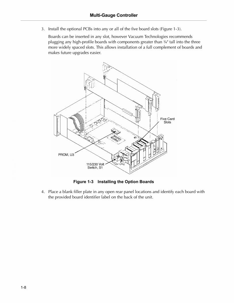
3. Install the optional PCBs into any or all of the five board slots (Figure 1-3).
Boards can be inserted in any slot, however Vacuum Technologies recommends plugging any high-profile boards with components greater than ¾" tall into the three more widely spaced slots. This allows installation of a full complement of boards and makes future upgrades easier.
Figure 1-3 Installing the Option Boards
4. Place a blank filler plate in any open rear panel locations and identify each board with the provided board identifier label on the back of the unit.
1-8

Multi-Gauge Controller
DR
AF
T 2
/6/0
4
5. Verify that:
❑ Line voltage selector S1 is correctly positioned
❑ All boards are properly seated and not touching each other
❑ All cables are properly plugged in
❑ There is no loose hardware (metal parts) inside the unit
6. Replace the cover and secure it with two screws.
7. Mount the unit using the desired rack-mounting kit, then attach the appropriate external gauge and system cables.
NOTE For optimum visibility, Vacuum Technologies recommends that the unit be mounted at or below eye level.
1-9

Multi-Gauge Controller D
RA
FT
2/6
/04
This page intentionally left blank.

Multi-Gauge Controller
DR
AF
T 2
/6/0
4
Section 2. Operating Instructions
Except for the power switch on the rear panel, all functions and parameters are accessible through the front panel keyboard. Pressure readings, prompts and annunciators are LCD-based.
Operations consist of:
❑ Section 2.1 “Setting Parameters”
❑ Section 2.2 “Operating the Multi-Gauge” on page 2-2
2.1 Setting ParametersWhen programming the Multi-Gauge, it may be necessary to set values for the system parameters such as sensitivity, gas correction, setpoints.
To set parameters:
1. Select the function by pressing the appropriate key or keys.
The present value of the parameter appears with its left-most digit flashing and the appropriate annunciator illuminates.
❑ Press the up or down arrow until the desired value for the flashing digit is reached.
❑ Press F to move to the next digit in sequence.
❑ Use the up or down arrows to change the flashing digit.
2. Continue until all digits have been set.
After several seconds, the front panel reverts back to reading pressure.
NOTE ❑ If an illegal entry is attempted, such as 0.00 for sensitivity, Err appears followed by the default value for that parameter. The default value is applied until the parameter is correctly reprogrammed.
❑ Press F during the digit-setting procedure to advance from one flashing digit to the next. Also use F to fast-forward to the end of the procedure. This allows for the viewing of all the settings and quickly exiting the routine.
2-1
Multi-Gauge Controller D
RA
FT
2/6
/04
2.2 Operating the Multi-Gauge1. Turn on the POWER switch on the rear panel and watch the front panel.
The type of PCB installed appears on the front panel in the left-most position, as viewed from the front.
Either:
❑ One of the four gauge identifiers (UHV, BA, CC, or AUX) illuminates with a 1.
❑ No gauge indicators light, but the thermocouple identifier illuminates with a 1.
NOTE The thermocouple identifier is used for the ConvecTorr also.
2. Press CHAN.
The gauge identifier changes to reflect the boards installed in the unit. If more than one of a type of board is installed, the gauge number changes to 2 or 3, as required, retaining the same gauge type (UHV 1, UHV 2, BA1, BA2, etc.). If no identifiers are illuminated, or they do not match the type of board installed, refer to Section 3 “Troubleshooting”.
3. Press CHAN to select the desired channel.
4. Press the proper key to activate the desired function.
For example, to assign and program set points for UHV2:
1. Scroll through the gauges using CHAN until UHV2 appears on the front panel.
2. Press SETPT. Programmed setpoints trigger from the UHV2 board. This applies to all functions, as well as to turning the gauge emission on and off. Whenever a function is selected or activated, it applies only to the gauge channel indicated by the identifiers or the Thermocouple identifier, if no identifiers are lit. The exceptions are UNITS, DIGIT, and KBAUD, which are common to all channels.
2-2

Multi-Gauge Controller
DR
AF
T 2
/6/0
4
2.2.1 Access Codes
Multi-Gauge offers several keypad-based hidden features that provide some system protection which require an access code.
To enter the access code:
1. Press F VAC.
2. Use the up and down arrow keys to select the appropriate two-digit code.
The functions and their respective codes are given in Table 2-1.
Table 2-1 Functions and Access Codes
Function Code Description
Lock Keypad A27 Allows only the CHAN channel select function and the F VAC access code function. all other keypad functions show the error code E14 for several seconds to indicate that an illegal keypad entry was made.
Unlock Keypad A33 Removes keypad lockout and permits any function.
Reset Unit A81 Resets the Multi-Gauge and returns all parameters to their default values:❑ Including Thermocouple calibration points and programmed setpoints❑ Excluding the serial communication baud rate and parity
Override E02/E06 A52 Ion gauge ignores pressure bursts and re-illuminates if a grid voltage error is detected.
Normal Operation A56 Default mode. Normal error code operation.
2-3

Multi-Gauge Controller D
RA
FT
2/6
/04
This page intentionally left blank.
Multi-Gauge Controller
DR
AF
T 2
/6/0
4
Section 3. Troubleshooting
The included troubleshooting procedures aid in determining failures to the board. For further troubleshooting assistance or for the repair or replacement of a board, contact Vacuum Technologies service at 1-800-882-7426 or 781-861-7200 within the U.S.
This section is comprised of:
❑ Section 3.1 “Keyboard Commands”
❑ Section 3.2 “Error Codes”
❑ Section 3.3 “Changing Line Fuses” on page 3-3
❑ Section 3.4 “Changing the PROM” on page 3-3
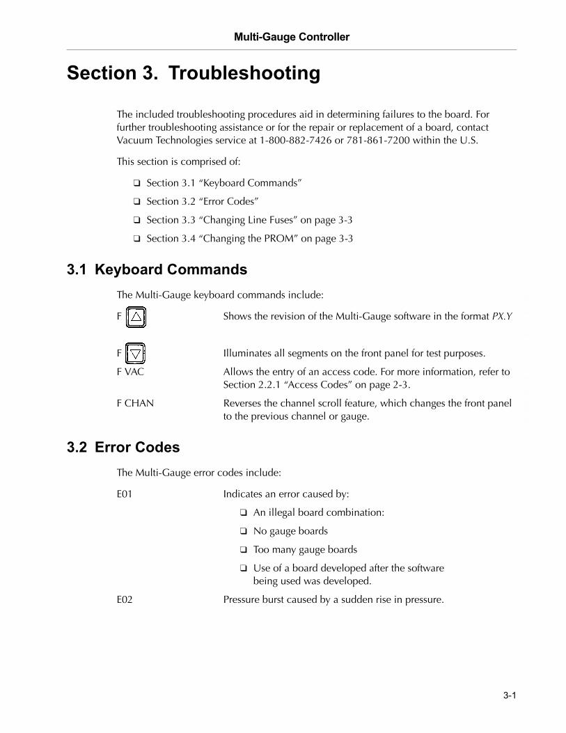
3.1 Keyboard CommandsThe Multi-Gauge keyboard commands include:
F Shows the revision of the Multi-Gauge software in the format PX.Y
F Illuminates all segments on the front panel for test purposes.
F VAC Allows the entry of an access code. For more information, refer to Section 2.2.1 “Access Codes” on page 2-3.
F CHAN Reverses the channel scroll feature, which changes the front panel to the previous channel or gauge.
3.2 Error CodesThe Multi-Gauge error codes include:
E01 Indicates an error caused by:
❑ An illegal board combination:
❑ No gauge boards
❑ Too many gauge boards
❑ Use of a board developed after the software being used was developed.
E02 Pressure burst caused by a sudden rise in pressure.
3-1

Multi-Gauge Controller D
RA
FT
2/6
/04
E03 No ion current flow/measurement signal caused by:
❑ A bad BA-UHV or missing collector cable connection
❑ A bad electrometer
❑ Emission current too low
❑ Cold cathode pressure <1 x 10⁻⁸ Torr.
E04 Filament overcurrent caused by a shorted filament circuit
E05 Filament undercurrent caused by:
❑ An open filament; cable not connected
❑ A bad control board or one that is installed incorrectly
E06 Grid voltage low caused by a:
❑ Grounded grid
❑ Bad grid supply
❑ Bad EB degas supply
E07 Overtemperature caused by a defective fan; temperature inside unit over 65 °C.
E08 Board logic failure
E09 Overpressure – Indicated pressure is above high pressure limit of the ion gauge or capacitance manometer gauge
E11 Plug-in board power supply failure
E12 Underpressure
E13 Insufficient current
E14 Invalid keypad function – Keypad is locked out
E15 Negative Capacitance Diaphragm input, beyond VAC range
3-2

Multi-Gauge Controller
DR
AF
T 2
/6/0
4
3.3 Changing Line Fuses
NOTE For continued protection against fire, both fuses must be replaced with fuses of the same type and rating as originally supplied.
If it is necessary to change the AC line fuses, due for example to age or overload, there are two fuses located on top of the power entry module. The fuses are held by two holders inside the top of the module marked with the outline of the fuses.
To access the fuses:
1. Remove the power cord.
2. Pry out the cover of the module with a small screwdriver.
3.4 Changing the PROMThe mother board PROM (U3) is replaced whenever the software is upgraded to operate newly-designed option boards or to correct system bugs.
CAUTION Observe all Warnings and Cautions printed on the cover.
To protect against damaging electrostatic discharge, follow static preventive procedures (i.e., use a conductive wrist strap) when handling the PROM.
To change the PROM:
1. Unplug the line cord.
2. Remove the two screws at the top rear of the unit, pivot the cover up and back to disengage the front lip, and lift off the cover.
3. Remove any PCB required to easily access the PROM.
Use extreme care when removing the chip so as not to damage the mother board.
4. Use a chip extractor to remove the PROM by prying the PROM up evenly on all sides so as not to bend the pins or damage the socket.
3-3

Multi-Gauge Controller D
RA
FT
2/6
/04
5. Straighten the pins on the PROM by holding each side against a flat surface and pressing the pins gently (Figure 3-1).
Figure 3-1 Straightening the Pins
6. Align the notch on the PROM with the notch in the socket (Figure 3-2).
7. Install the notch on the PROM on the side closest to the unit front panel.
Figure 3-2 Location of Chip and Socket Notches
8. Ensure that none of the pins are bent under the chip.
3-4

Multi-Gauge Controller
DR
AF
T 2
/6/0
4
9. Align the pins on the chip with the corresponding holes in the socket, tilt the chip slightly to partially insert one side before the other (Figure 3-3).
Figure 3-3 Installing the Chip
10. Check that the pins are properly seated in the socket and press down firmly on the center of the chip until it is fully seated.
3-5

Multi-Gauge Controller D
RA
FT
2/6
/04
This page intentionally left blank.
Multi-Gauge Controller
DR
AF
T 2
/6/0
4
Appendix A. Gas Correction Factor Table
Table A-1 on page A-2 lists the relative gauge gas correction factors for various gases.
WARNING Do not assume that the use of the gases listed in this table are safe with hot filament gauge controllers.
The values in Table A-1 are derived by empirical methods substantiated by measurements reported in literature. This table has been compiled and published by Robert L. Summers of Lewis Research Center, NASA Technical Note TND-5285, National Aeronautics and Space Administration, Washington, DC, June 1969.
To automatically convert readings of the Multi-Gauge Controller (normally calibrated for nitrogen):
❑ Enter the relative gas correction constant through the front panel key function F GAS CORR.
When the gas constant is entered, the gauge divides the result by the gas correction constant and displays the correct adjusted value.
A proper understanding for the transformation of the result is still, however, required. The correction for different gas species is purely mathematical. The tube sensitivity tube is affected by different gases which, in turn, is responsible for the tube output being manipulated by the pressure equation. In addition, There is loss in resolution of the instrument when gas correction constants are used. The loss in resolution becomes more apparent as the correction constants approach 0.5 from either direction. When the correction constants are 0.1 or 10, the tube output is 1/10 or 10 times normal. This causes the instrument to lose the high vacuum decade or the near atmosphere decade, respectively.
NOTE Some gases have several correction factors listed. In such cases, the top number is the most commonly-used value.
A-1

Multi-Gauge Controller D
RA
FT
2/6
/04
Table A-1 Gas Correction Factor Table
A-2

Multi-Gauge Controller
DR
AF
T 2
/6/0
4
Table A-1 Gas Correction Factor Table (Continued)
A-3

Multi-Gauge Controller D
RA
FT
2/6
/04
This page intentionally left blank.

Multi-Gauge Controller
DR
AF
T 2
/6/0
4
Appendix B. UHV Board
The UHV control PCB (Part No. L8321301), when used with a Multi-Gauge unit, contains all required circuitry to operate a UHV-24 or similar ion gauge. It can be installed in any one of the five slots in the Multi-gauge unit, however, since it is a high-profile board, Vacuum Technologies recommends that it be put into one of the three right-hand slots (as viewed from the front of the unit) for maximum flexibility. After installation, place the UHV label on the area provided to identify the card after the cover is installed.
This appendix includes:
❑ Section B.1 “Specifications”
❑ Section B.2 “Installation” on page B-3
❑ Section B.3 “Calibration and Adjustments” on page B-4
❑ Section B.4 “UHV Control Card Operation” on page B-4
❑ Section B.5 “Recorder Output” on page B-6
B.1 Specifications
Table B-1 UHV Board Specifications
Specification Description
Electrometer Accuracy >10−10 Torr ± 5 percent of ion current reading (ion current = >10 pA)<10−10 Torr ± 20 percent of ion current reading (ion current ≤ 10 pA, I > 4 pA)
Emission Current Range Default is 4.00 mA. Currents can be set from 10 µA to 9.99 mA through the front panel keypad of the unit. The emission current remains constant as long as the pressure is <1 x 10⁻⁵ Torr or the emission current is set to 1.00 mA. The Multi-Gauge automatically reduces the current by a factor of 10 when the pressure is >5 x 10⁻⁵ Torr and the emission current is set to ≥ 1.01 mA.
Alternate Filament Selection Automatic for a dual filament gauge. The EMIS 2 indicator illuminates to indicate that the second filament is active.
Overpressure Protection Automatic gauge tube turnoff when pressure reaches ≥ 1 x 10⁻³ Torr.
Degas Electron beam bombardment: 600 V at 47 mA. Activates only if pressure is <10−5 Torr and no other board is degassing.Automatic timeout is approximately 15 to 25 minutes depending on the Multi-Gauge card configuration.
B-1

Multi-Gauge Controller D
RA
FT
2/6
/04
NOTE ❑ Emission current must be increased to 9.99 mA for measuring with UHV range of below 1x10⁻¹⁰ Torr
❑ Emission current should be lowered to 0.1 mA or lower when accurate measuring from 1x10⁻⁴ or higher is desired.
Recorder Output 1 V/decade log-linear output. Two-conductor Micro Jax connector plugs are supplied with the board.Recorder output reflects changes in sensitivity and gas correction factors.
Fault Detections ❑ E03 � No ion current❑ E06 � Emission current or amplifier fault, check emission current setting;
low grid voltage (low degas voltage when in Degas mode) ❑ E05 � Open filament or no filament current❑ E04 � Filament circuit/cable short❑ E07 � Overtemperature shutdown - gauge power shuts off when internal
temperature reaches 65 °C.For more information, refer to Section 3.2 �Error Codes� on page 3-1.
Cable Length Standard cables with lengths of 10, 25, 50, 75, and 100 feet are stocked.Longer cables are available on special order (Table B-2). Connections are made at the rear of the card as shown in Figure B-1.
Sensitivity The default is 25 per Torr. Can be set from 0.1 to 99.9 per Torr through the keypad.
Gas Correction 1.00 (N2) is the default. Can be set from 0.01 to 9.99 through the keypad. For more information, refer to Appendix A �Gas Correction Factor Table�.
Table B-1 UHV Board Specifications (Continued)
Specification Description
NOTE Measurements in the ultra-high vacuum range may be inaccurate or impossible due to increased leakage currents and other effects due to long cable lengths. Use rigidly mounted teflon low-capacitance cable to avoid tribolectric and leakage effects.
B-2

Multi-Gauge Controller
DR
AF
T 2
/6/0
4
B.2 Installation
Table B-2 and Figure B-1 present the information required to connect the board.
Figure B-1 UHV Card Connections
Table B-2 Cable Lengths and Sizes
Length (in feet) Wire Size (AWG) Each Wire
Up to 50 18
75 16
100 14
200 12
500 8
B-3
Multi-Gauge Controller D
RA
FT
2/6
/04
B.3 Calibration and Adjustments
The system automatically self-calibrates to compensate for component variations with temperature and time.
B.4 UHV Control Card Operation
Multi-Gauge indicates the presence of a UHV control card by illuminating UHV when the channel into which the card is plugged is selected using CHAN.
On initial power up the front panel shows OFF, indicating that the gauge is not measuring pressure.
To measure pressure:
❑ Press EMIS.
The front panel shows hyphens [- - -] for several seconds along with EMIS.
If the emission is successfully established, the front panel indicates pressure by illuminating EMIS. In addition, a 2 appears if the gauge tube’s second filament is operating, which indicates that the first filament is burned out.
If an error message appears, refer to Section 3 “Troubleshooting”.
To stop measuring pressure:
NOTE With software revision 2.4 or later, the keypad sequence F EMIS turns on filament 2 from the OFF state. EMIS still turns off the emission.
❑ Press EMIS.EMIS goes off and OFF appears on the front panel, indicating that the gauge filament has been shut off. Pressing the EMIS button also removes any error messages from the front panel and emission can be retried, if desired.
B-4
Multi-Gauge Controller
DR
AF
T 2
/6/0
4
To activate the DEGAS function:
NOTE Multi-Gauge degases only one ion gauge at a time.
1. Ensure that both:
❑ The ion gauge is on and displaying a pressure reading less than 1 x 10⁻⁵ Torr(1.33 x 10⁻⁵ mBar or 1.33 x 10⁻³ PASCAL), and
❑ That no other board is degassing
2. Press DEGAS.
If the pressure condition in step 1 is met, degassing of the gauge begins. The front panel display shows hyphens [- - -] along with DEGAS. Take steps to prevent inadvertent venting of the system to protect the gauge since the gauge cannot read pressure when in the DEGAS mode as the collector lead is also being bombarded.
NOTE The UHV board utilities electron beam bombardment degassing is <25 Watts. Grid voltage is raised to 600 VDC and emission current is set at 47 mA.
If an error message appears, refer to Section 3 “Troubleshooting”.
There are three ways to deactivate the DEGAS function:
❑ Do nothing. After approximately fifteen minutes, the computer in the unit automatically turns off the DEGAS function. Emission also shuts off for <500 msec, then turns back on with the front panel displaying hyphens [- - -] while emission is re-established.
❑ Press DEGAS. This terminates the DEGAS function, leaving the tube on to read pressure after the momentary emission shut-off and re-establishment.
❑ Press EMIS. This simultaneously turns off the DEGAS and gauge EMISSION functions. The front panel reads OFF.
B-5

Multi-Gauge Controller D
RA
FT
2/6
/04
B.5 Recorder Output
To use the recorder output feature, assemble a cable to the Micro Jax plug supplied with the UHV control card. Vacuum Technologies strongly recommends using a coaxial cable to maintain compliance with FCC regulations. Refer to Figure B-2 for instructions on assembling the cable.
Figure B-2 Assembling the Cable/Plug
Any recorder with an input impedance greater than 2,000 Ohms and which has a full scale input range of +10 V can be used.
The recorder output reflects the reading on the front panel and does not require adjustments to compensate for different emission or sensitivity settings.
When the gauge is:
❑ Off The output is 10 V.
❑ Degassing The output is 0 V.
2. Strip the outer cover 0.2".
3. Solder the center conductor.
4. Crimp the tabs onto the shield and solder.0.1"
0.2"
1. Strip to 0.1" of bar wire.
B-6

Multi-Gauge Controller
DR
AF
T 2
/6/0
4
The output characteristics are shown in Figure B-3.
Figure B-3 Recorder Output Characteristics
The algorithm below converts the recorder output voltage to pressure.
Example: recorder output = 4.28 VDC
To get the exponent take the integer part of voltage output which is 4 and subtract 11:
4 – 11 = –7 (E-7)
To find the mantissa, take the fractional portion and add .1 to it and divide by .11:
(.28 + .1)/.11 = 3.45
Result: 4.28 VDC = 3.45E-7 Torr
B-7

Multi-Gauge Controller D
RA
FT
2/6
/04
This page intentionally left blank.

Multi-Gauge Controller
DR
AF
T 2
/6/0
4
Appendix C. Thermocouple Board
The Thermocouple Printed Circuit Control Board (Part No. L6430301), when used with a Multi-Gauge unit, contains all the circuitry required to operate four Model 531 thermocouple gauge tubes. It can be installed in any one of the five slots in the Multi-Gauge basic unit. After installation, place the Thermocouple label on the area provided to identify the card after the cover is installed. Up to two Thermocouple cards can be installed for a total of eight available thermocouples.
This appendix describes:
❑ Section C.1 “Thermocouple Principles of Operation”
❑ Section C.2 “Specifications” on page C-2
❑ Section C.3 “Installation” on page C-3
❑ Section C.4 “Operation” on page C-4
❑ Section C.5 “Calibration” on page C-4
❑ Section C.6 “Auto Turn-On” on page C-5
❑ Section C.7 “Recorder Output” on page C-6
C.1 Thermocouple Principles of Operation
A thermocouple operates on the principle that, at sufficiently low pressures, the thermal conductivity of the gas decreases with a decrease in pressure. A thermocouple is attached to a heater wire in which the temperature is raised to approximately 350 °C by passing a current through the wire. When constant power is maintained through the heater wire, the temperature measured by the thermocouple changes with pressure. This change is directly related to the heat conducted away by the gas in the environment. The electromotive force (emf) measured from the thermocouple is read on a scale which has been calibrated for pressure.
The response of the thermocouple is also affected by factors other than pressure. For example, the tube is typically calibrated for nitrogen or air. If the residual gas in the vacuum system is some other gas, the pressure reading can be affected. Hydrogen and helium conduct heat away from the thermocouple more rapidly than air. This leads to a pressure reading that is higher than the actual pressure. Contaminants such as oil, dust, and other chemicals can also change the surface of the thermocouple and heater which, in turn, change the ability of the thermocouple to dissipate the heat and affect the pressure reading.
C-1

Multi-Gauge Controller D
RA
FT
2/6
/04
Because the thermocouple gauge tube is a thermal response device, the ability of the tube to respond to abrupt pressure changes is limited by the mass of the thermocouple and heater. If this combination is very small, the tube responds more rapidly than a tube with larger wire sizes.
In general, thermocouple gauge tubes are used to gain an indication of the vacuum in a system rather than an accurate measurement. Because so many factors can affect the output of the tube, unless special care and precautions are taken, the pressure read on the control is usually accurate only to within ± 30 percent of the indicated reading.
For accurate results:
❑ Position thermocouple gauge tubes on the vacuum system so that contaminants do not collect in the tube.
❑ Position the tube port down to prevent mechanical pump oil and other contaminants from building up in the tube.
C.2 SpecificationsTable C-1 Thermocouple Board Specifications
Specification Description
Software required Revision P1.1 or later
Pressure range 2 Torr to 1 x 10⁻³ Torr
Thermocouple heater current
165 mA ±10%
Thermocouple Resistance Approximately 1.4 Ohms from pin to pin
Cable length Standard lengths of 10, 25, 50, 75, and 100 feet are available from stock.Longer lengths (up to 500 feet) are available on special order. Connections are made to the rear of the card.
Recorder output 0 to 10 V non-linear. See Figure C-1 for connections of user-supplied wiring.Vacuum Technologies recommends the use of shielded wiring to maintain compliance with FCC regulations for radiated emissions. The recorder output does not reflect ATM or VAC settings.
Fault Detections No cable or open Thermocouple circuit; Thermocouple power supply fault.For more information, refer to Section 3.2 �Error Codes� on page 3-1.
C-2

Multi-Gauge Controller
DR
AF
T 2
/6/0
4
C.3 Installation
Use Table C-2 and Figure C-1 to understand the signal pin out pattern.
Figure C-1 37-Pin Connector
Table C-2 Signal and Pin Assignments
Signal Pin No.
TC1 rec out 3
TC1 rec gnd 20
TC2 rec out 10
TC2 rec gnd 24
TC3 rec out 15
TC3 rec gnd 27
TC4 rec out 6
TC4 rec gnd 31
C-3

Multi-Gauge Controller D
RA
FT
2/6
/04
C.4 Operation
Multi-Gauge indicates the presence of the Thermocouple card by illuminating the curved bar graph and the thermocouple is identified by the Thermocouple number just beneath the bar graph. The Thermocouple reading also appears on the front panel when there are no annunciators lit. Multi-Gauge also provides the capability to select any one of the installed thermocouples on the bar graph simultaneously with a main ion gauge, such as a UHV or Bayard-Alpert gauge, by using the up or down arrows. This causes the Thermocouple identifier to scroll through the installed thermocouples.
If two thermocouple cards are installed in the basic unit, Multi-Gauge assigns the identification:
❑ TC1, TC2, TC3, and TC4 to the left-most installed Thermocouple card (as viewed from the front of the unit).
❑ TC5, TC6, TC7, and TC8 to the right-most installed card.
C.5 Calibration
NOTE Since the Multi-Gauge calibrates the thermocouple to any ATM or VAC setting, take care in applying these functions accurately.
Before using the thermocouple card for pressure measurements, first set the atmosphere and vacuum readings using the ATM and VAC keys:
1. Press CHAN and select the desired thermocouple to set the atmosphere reading. Make sure that the thermocouple is exposed to atmospheric pressure.
2. Press ATM.
The front panel reads 760 Torr, or the equivalent in mBar or Pascal, as desired.
3. Press CHAN and select the desired thermocouple to set the vacuum reading.
4. Expose the selected thermocouple to a known vacuum level:
❑ To as high as 9.9 x 10⁻² Torr
❑ To mBar (9.9 x 100 Pascal)
❑ To a vacuum level lower than 10−3 Torr or mBar (10−1 Pascal)
5. Press VAC.
The front panel shows the most recent vacuum setting, initially 1.0 x 10⁻³ Torr, with the most significant digit flashing.
6. Set the front panel to the vacuum level desired to calibrate the thermocouple.
The thermocouple is now calibrated.
C-4

Multi-Gauge Controller
DR
AF
T 2
/6/0
4
C.6 Auto Turn-On
Use a thermocouple card in conjunction with an ion gauge card to program a thermocouple to automatically turn on emission for an ion gauge. The AUTO-ON feature allows program-ming of the turn-on level between 1 x 10⁻³ Torr and 5 x 10⁻³ in Torr or mBar units (1 x 10⁻¹ to 5 x 10⁻¹ in Pascal) for all Vacuum Technologies ion gauges. The 564 Broad Range Bayard-Alpert gauge can also be set to turn on between 1 x 10⁻² and 5 x 10⁻² Torr or mbar (1 x 100 and 5 x 100 Pascal).
NOTE Every thermocouple is available as a turn-on source, regardless of whether it has a setpoint assigned to it or whether it has been assigned to turn on another ion gauge.
To program AUTO-ON:
1. Press CHAN and select the ion gauge for automatic turn on.
2. Press AUTO-ON.
SELECT AUTO-ON is illuminated along with the number of the first available thermocouple or the number of a previously assigned thermocouple. The front panel shows a pressure setting if assigned or 0.00 mantissa if not assigned.
3. Press AUTO-ON again to select the next available thermocouple.
❑ Change the flashing digit values to set the turn-on pressure.
❑ To cancel the Auto turn-on, set the mantissa to 0.00.
Once all flashing digits are set, AUTO-TURN ON programming is complete.
NOTE When the Auto Turn-On is enabled for a given ion gauge, EMIS can still be used to turn off the ion gauge. Turning off the ion gauge with EMIS disables the Auto Turn-On setting and requires the entry of the Auto-On programming routine to re-activate the Auto-On setting.
C-5
Multi-Gauge Controller D
RA
FT
2/6
/04
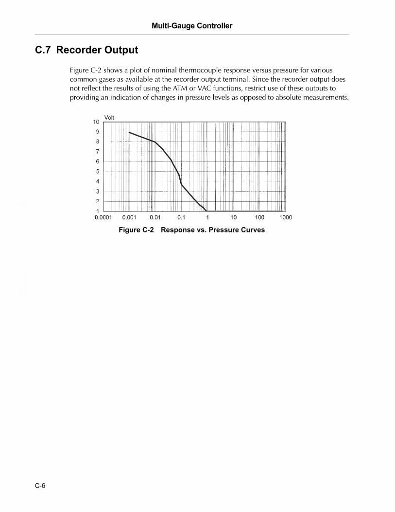
C.7 Recorder Output
Figure C-2 shows a plot of nominal thermocouple response versus pressure for various common gases as available at the recorder output terminal. Since the recorder output does not reflect the results of using the ATM or VAC functions, restrict use of these outputs to providing an indication of changes in pressure levels as opposed to absolute measurements.
Figure C-2 Response vs. Pressure Curves
C-6
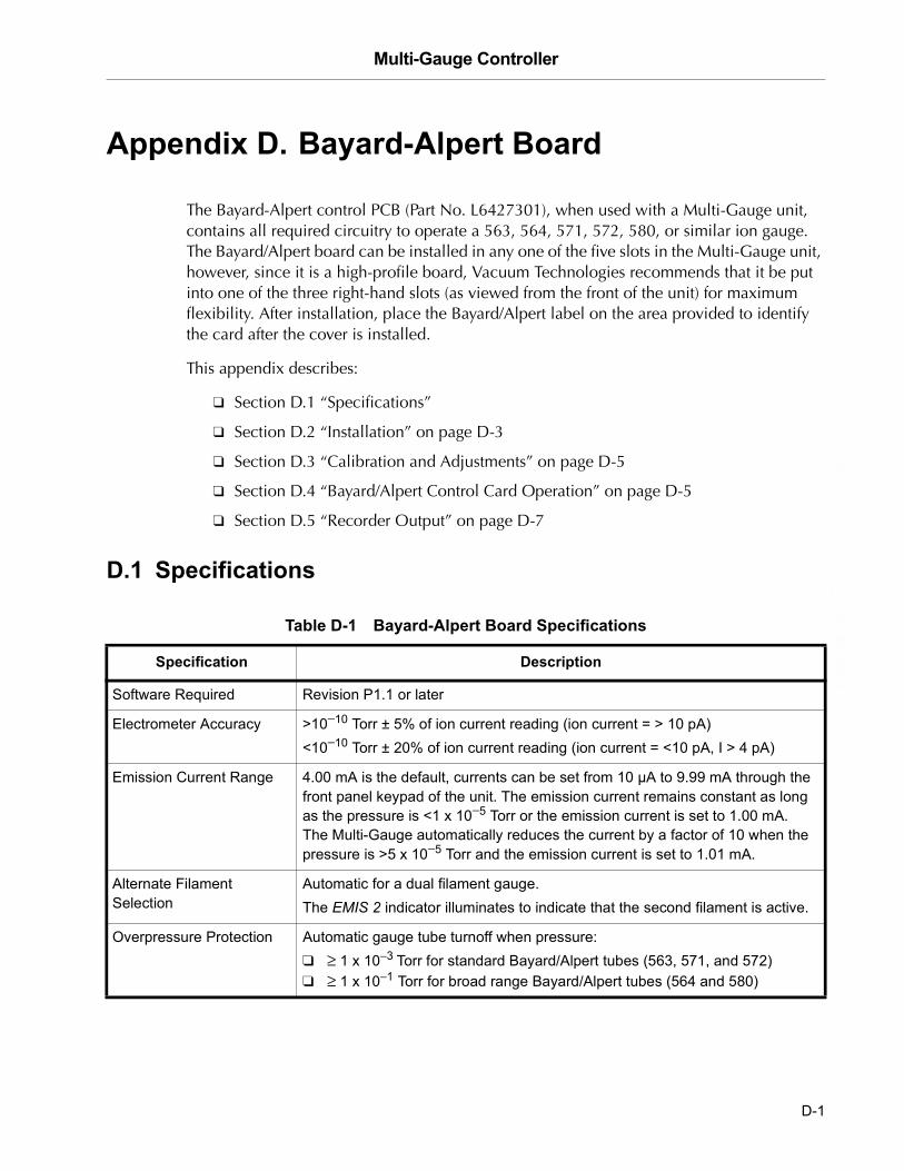
Multi-Gauge Controller
DR
AF
T 2
/6/0
4
Appendix D. Bayard-Alpert Board
The Bayard-Alpert control PCB (Part No. L6427301), when used with a Multi-Gauge unit, contains all required circuitry to operate a 563, 564, 571, 572, 580, or similar ion gauge. The Bayard/Alpert board can be installed in any one of the five slots in the Multi-Gauge unit, however, since it is a high-profile board, Vacuum Technologies recommends that it be put into one of the three right-hand slots (as viewed from the front of the unit) for maximum flexibility. After installation, place the Bayard/Alpert label on the area provided to identify the card after the cover is installed.
This appendix describes:
❑ Section D.1 “Specifications”
❑ Section D.2 “Installation” on page D-3
❑ Section D.3 “Calibration and Adjustments” on page D-5
❑ Section D.4 “Bayard/Alpert Control Card Operation” on page D-5
❑ Section D.5 “Recorder Output” on page D-7
D.1 Specifications
Table D-1 Bayard-Alpert Board Specifications
Specification Description
Software Required Revision P1.1 or later
Electrometer Accuracy >10−10 Torr ± 5% of ion current reading (ion current = > 10 pA)<10−10 Torr ± 20% of ion current reading (ion current = <10 pA, I > 4 pA)
Emission Current Range 4.00 mA is the default, currents can be set from 10 µA to 9.99 mA through the front panel keypad of the unit. The emission current remains constant as long as the pressure is <1 x 10⁻⁵ Torr or the emission current is set to 1.00 mA. The Multi-Gauge automatically reduces the current by a factor of 10 when the pressure is >5 x 10⁻⁵ Torr and the emission current is set to 1.01 mA.
Alternate FilamentSelection
Automatic for a dual filament gauge. The EMIS 2 indicator illuminates to indicate that the second filament is active.
Overpressure Protection Automatic gauge tube turnoff when pressure: ❑ ≥ 1 x 10⁻³ Torr for standard Bayard/Alpert tubes (563, 571, and 572)❑ ≥ 1 x 10⁻¹ Torr for broad range Bayard/Alpert tubes (564 and 580)
D-1

Multi-Gauge Controller D
RA
FT
2/6
/04
Degas Resistive, 40 Watts.Can activate only if pressure is <10−5 Torr and no other board is degassing.Automatic timeout of approximately 3 hours.
Recorder Output 1 V/decade log-linear output. Two-conductor Micro Jax connector plug supplied with board.Recorder output reflects changes in sensitivity and gas correction factors.
Fault Detections ❑ E03 � No ion current❑ E06 � Emission current or amplifier fault, check emission current setting;
low grid voltage (low degas voltage when in Degas mode) ❑ E05 � Open filament or no filament current❑ E04 � Filament circuit/cable short❑ E07 � Overtemperature shutdown � gauge power shuts off when internal
temperature reaches 65 °C.For more information, refer to Section 3.2 �Error Codes� on page 3-1.
Cable Length Standard cables with lengths of 10, 25, 50, 75, and 100 are available from stock. Longer cables are available on special order (Table D-2). Connections are made at the rear of the card as shown in Figure D-1.
Sensitivity The default is:❑ 10.0 per Torr for standard Bayard/Alpert tubes (563, 571, and 572)❑ 8.0 per Torr for broad range Bayard/Alpert tubes (564 and 580). Can be set from 0.1 to 99.9 per Torr through the keypad.
Gas Correction The default is 1.00 (N2) is the default. Can be set from 0.01 to 9.99 through the keypad. For more information, refer to Appendix A �Gas Correction Factor Table�.
Table D-1 Bayard-Alpert Board Specifications (Continued)
Specification Description
NOTE Vacuum Technologies offers reference ionization Bayard/Alpert gauges, which are sealed off at approximately 5E-6 Torr. These gauges are extremely helpful in troubleshooting a vacuum system problem by isolating the defective component. Reference ion gauge tubes are NOT NIST traceable calibrated gauges but act only as a load for the ion gauge controller.
NOTE Measurements in the ultra-high vacuum range may be inaccurate or impossible due to increased leakage currents and other effects due to long cable lengths. Use rigidly mounted teflon low-capacitance cable to avoid tribolectric and leakage effects.
D-2

Multi-Gauge Controller
DR
AF
T 2
/6/0
4
D.2 Installation
To install the card:
1. Use Table D-2 and Figure D-1 to connect the board.
Figure D-1 Bayard Alpert Card Connections
Table D-2 Cable Lengths and Sizes
Length (in feet) Wire Size (AWG) Each Wire
Up to 50 18
75 16
100 14
200 12
500 8
D-3

Multi-Gauge Controller D
RA
FT
2/6
/04
2. Set a jumper on the Bayard/Alpert board to identify the type of Bayard/Alpert tube being used.
❑ To operate a Standard Bayard/Alpert tube (563, 571, or 572), position the jumper as shown in Figure D-2 (left). The jumper is set at the factory to the standard Bayard/Alpert tube position.
❑ To operate a Broad range Bayard/Alpert tube (564 or 580), position the jumper as shown in Figure D-2 (right).
Figure D-2 Jumper Positions
NOTE When using the Multi-Gauge Bayard/Alpert card to operate an early model (such as the 580 or another manufacturer’s nude gauge), it may be necessary to cut the GRI support pin flush with the standoff as shown in the Broad-Range Tube illustration. Failure to do so can damage the Bayard/Alpert card. Wear eye protection when cutting the pin.
The connector plate has been removed for illustration clarity.
Standard Tube Broad-Range Tube
D-4
Multi-Gauge Controller
DR
AF
T 2
/6/0
4
D.3 Calibration and Adjustments
The system automatically self-calibrates to compensate for component variations with temperature and time.
D.4 Bayard/Alpert Control Card Operation
Multi-Gauge indicates the presence of a Bayard/Alpert control card by illuminating Bayard/Alpert when the channel into which the card is plugged is selected using CHAN.
On initial power up, OFF appears on the front panel, indicating that the gauge is not measuring pressure.
To measure pressure:
❑ Press EMIS.The front panel indicates hyphens [- - -] for several seconds along with EMIS.
❑ If the emission is successfully established, the front panel indicates pressure by illuminating EMIS. In addition, a 2 is lit if the gauge tube’s second filament is operating, an indication that the first filament is burned out.
❑ If an error message appears, refer to Section 3 “Troubleshooting”.
NOTE With software revision 2.4 or later, the keypad sequence F EMIS turns on filament 2 from the OFF state. EMIS still turns off the emission.
NOTE At pressures higher than 1 mTorr, performance is greatly improved by lowering the emission current to 0.1 mA or lower. This also prevents the gauge from giving false readings. This also raises the lowest readable pressure to 1 x 10⁻⁸ Torr, and even higher if set lower.
D-5

Multi-Gauge Controller D
RA
FT
2/6
/04
To stop measuring pressure:
❑ Press EMIS.EMIS goes off and OFF appears on the front panel, indicating that the gauge filament has been shut off. Pressing the EMIS button also removes any error messages from the front panel and emission can be retried, if desired.
To activate the DEGAS function:
NOTE Multi-Gauge degases only one ion gauge at a time.
1. Ensure that the ion gauge is on and displaying a pressure reading of less than 1 x 10⁻⁵ Torr (1.33 x 10⁻⁵ mBar or 1.33 x 10⁻³ PASCAL) and that no other board is degassing.
2. Press DEGAS.
If the pressure condition in step 1 is met, degassing of the gauge begins. The front panel reads pressure along with DEGAS.
If an error message appears, refer to Section 3 “Troubleshooting”.
There are three ways to deactivate the DEGAS function:
❑ Do nothing. After approximately fifteen minutes, the computer in the unit automatically turns off the DEGAS function. Emission also shuts off for <500 msec, then turns back on with the front panel reading showing hyphens [- - -] while emission is re-established.
❑ Press DEGAS. This terminates the DEGAS function, leaving the tube on to read pressure after the momentary emission shut-off and re-establishment.
❑ Press EMIS. This simultaneously turns off the DEGAS and gauge EMISSION functions. The front panel reads OFF.
D-6

Multi-Gauge Controller
DR
AF
T 2
/6/0
4
D.5 Recorder Output
To use the recorder output feature, assemble a cable to the Micro Jax plug supplied with the Bayard/Alpert control card. Vacuum Technologies strongly recommends using a coaxial cable to maintain compliance with FCC regulations. Refer to Figure D-3 for instructions on assembling the cable.
Figure D-3 Assembling the Cable/Plug
Any recorder with an input impedance greater than 2,000 Ohms and which has a full scale input range of +10 V can be used.
The output characteristics are shown in Figure D-4.
Figure D-4 Recorder Output Characteristics
2. Strip the outer cover 0.2".
3. Solder the center conductor.
4. Crimp the tabs onto the shield and solder.0.1"
0.2"
1. Strip to 0.1" of bar wire.
D-7
Multi-Gauge Controller D
RA
FT
2/6
/04
The algorithm below converts the recorder output voltage to pressure.
Example: recorder output = 4.28 VDC
To get the exponent take the integer part of voltage output which is 4 and subtract 11:
4 – 11 = –7 (E-7)
To find the mantissa, take the fractional portion and add .1 to it and divide by .11:
(.28 + .1)/.11 = 3.45
Result: 4.28 VDC = 3.45E-7 Torr
The recorder output reflects the reading on the front panel and does not require adjustments to compensate for different emission or sensitivity settings. When the gauge is off, the output is 0 V.
D-8

Multi-Gauge Controller
DR
AF
T 2
/6/0
4
Appendix E. Cold Cathode Board
The Multi-Gauge Cold Cathode Board (Part No. L6433301) is designed to operate the Vacuum Technologies 524 (bakeable) and 525 (non-bakeable) gauge heads with cable lengths up to 500 feet. Its operating voltage is –2 kV and its nominal sensitivity is 5 A/Torr. The use of software linearization and dynamic power modulation allows a useful range exceeding 1 x 10⁻² to 1 x 10⁻⁷ Torr.
WARNING Cold Cathode Gauges require the use of a high voltage source which can be lethal. Proper grounding of the Multi-Gauge unit and the gauge head are necessary. Use extreme caution when working with these instruments; the instrument must be operated only by properly trained personnel. Do not operate the multi-gauge with the cover off.
The Cold Cathode board can be installed in any one of the five slots in the Multi-Gauge unit, however, since it is a high-profile board, Vacuum Technologies recommends that it be put into one of the three right-hand slots (as viewed from the front of the unit) for maximum flexibility. After installation, place the CC label on the area provided to identify the card after the cover is installed.
This appendix describes:
❑ Section E.1 “Theory of Operation” on page E-2
❑ Section E.2 “Specifications” on page E-3
❑ Section E.3 “Installation” on page E-4
❑ Section E.4 “Calibration and Adjustments” on page E-5
❑ Section E.5 “Cold Cathode Board Operation” on page E-5
❑ Section E.6 “Recorder Output” on page E-9
E-1

Multi-Gauge Controller D
RA
FT
2/6
/04
E.1 Theory of Operation
The cold cathode gauge represents one of the most popular ionization based methods of high vacuum measurement. Its simplicity, durability, and relatively low cost make this gauge an attractive choice for many high-vacuum gauging requirements, however, the cold cathode gauge has operational characteristics and limitations you should be aware of before using it in a system.
The gauge consists of a controller to provide the high voltage as well as a readout for the pressure, and a sensor that is connected to the system where pressure is to be monitored. The sensor can be of several types, a simple Penning type or a more complex magnetron structure. The latter type, Redhead magnetron, is used as an illustration in this discussion.
Figure E-1 illustrates the cross-section of the cold cathode gauge tube with an ionization chamber containing a cylindrical cathode with its end caps surrounded by a conducting metal wall. A high voltage supply is connected in series with a meter and the ionization chamber. A magnetic field of about 1000 gauss is introduced with flux lines parallel to the axis of the cathode.
Figure E-1 Figure 2. Cross-Section Drawing of Cold Cathode Gauge
When this tube is subjected to a total pressure below approximately 10−1 Torr, an electron is removed from the cathode by the strong electrostatic field, which then orbits around the cathode perpendicular to the magnetic field. The electron then collides with gas molecules present, ionizing them, and producing positively charged ions and free electrons. The resulting free electrons also travel in orbits about the cathode and ionize other gas molecules present. This avalanche effect takes milliseconds to arrive at a pressure-dependent final value. The positive ions are collected by the cathode and the resultant current is proportional to the pressure.
E-2

Multi-Gauge Controller
DR
AF
T 2
/6/0
4
To determine the ion current at a given pressure, the sensitivity of the tube must be known. The sensitivity is determined by the particular geometry of the tube. Model 524 and 525 gauges have a sensitivity of approximately 5 A/Torr. This means at 1 x 10⁻¹ Torr, the ion current is 500 mA. At the usual 2 kV supply voltage, this results in a power dissipation of 1000 W within the tube. The conditions outlined in the previous sentence to not occur in conventional tubes. Instead, current limiting is used so that the maximum current is approximately 1 mA, resulting in an upper pressure reading capability typically in the 10−3 Torr range.
With a Multi-Gauge Cold Cathode control board, pressure can be read from 1 x 10⁻² Torr to 1 x 10⁻⁸ Torr. This is accomplished by supplying a pulsating DC current to the tube. In operation, a cold cathode gauge requires a minimum DC voltage to fire. This threshold voltage is dependent upon pressure and reduces in value as the pressure rises.
E.2 Specifications
Table E-1 Cold Cathode Board Specifications
Specification Description
Software Required Revision P1.7 or later
Electrometer Accuracy >10−6 Torr ± 5% of ion current reading (ion current = > 5 µA)
Overpressure Protection Automatic gauge tube turnoff when pressure equals or exceeds 2 x 10⁻² Torr.
Recorder Output 1 V/decade log-linear output. Two-conductor Micro Jax connector plug supplied with board.Recorder output reflects changes in sensitivity and gas correction factors.
Fault Detections ❑ E03 � No ion current❑ E09 � Over pressure❑ E07 � Overtemperature shutdown -
gauge power shuts off when internal temperature reaches 65 °C.❑ E11 � High voltage failure or shortFor more information, refer to Section 3.2 �Error Codes� on page 3-1.
Cable Length Standard cables with lengths of 10, 25, 50, 75, and 100 feet are stocked. Longer cables are available on special order. Connections are made at the rear of the card as shown in Figure E-2.
Sensitivity The default is 5 A per Torr. Can be set from 0.1 to 99.9 per Torr through the keypad second function F SENS.
Gas Correction The default is 1.00 (N2). Can be set from 0.01 to 9.99 through the keypad second function F GAS CORR. For more information, refer to Appendix A �Gas Correction Factor Table�.
E-3
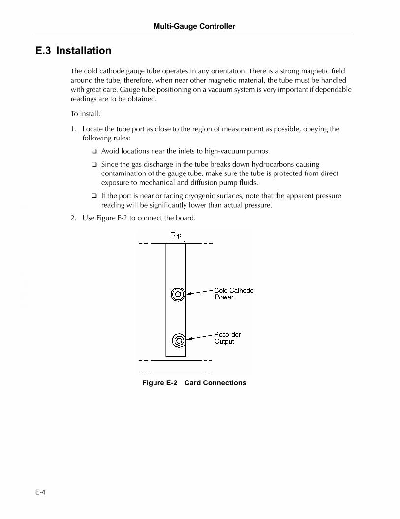
Multi-Gauge Controller D
RA
FT
2/6
/04
E.3 Installation
The cold cathode gauge tube operates in any orientation. There is a strong magnetic field around the tube, therefore, when near other magnetic material, the tube must be handled with great care. Gauge tube positioning on a vacuum system is very important if dependable readings are to be obtained.
To install:
1. Locate the tube port as close to the region of measurement as possible, obeying the following rules:
❑ Avoid locations near the inlets to high-vacuum pumps.
❑ Since the gas discharge in the tube breaks down hydrocarbons causing contamination of the gauge tube, make sure the tube is protected from direct exposure to mechanical and diffusion pump fluids.
❑ If the port is near or facing cryogenic surfaces, note that the apparent pressure reading will be significantly lower than actual pressure.
2. Use Figure E-2 to connect the board.
Figure E-2 Card Connections
E-4

Multi-Gauge Controller
DR
AF
T 2
/6/0
4
For further discussion on the theory and operation of cold cathode gauge vacuum measurement, use the following references:
❑ Dushman, S., Lafferty, J.M., SCIENTIFIC FOUNDATIONS OF VACUUM TECHNIQUE, John Wiley and Sons, Inc., Second Edition, New York, 1962
❑ Guthrie, A., VACUUM TECHNOLOGY, John Wiley & Sons, Inc., 1963
❑ Lewin, G., VACUUM SCIENCE AND TECHNOLOGY, McGraw-Hill, New York, 1965
❑ Redhead, P.A. et al, ULTRAHIGH VACUUM, Chapman and Hall, London, 1968.
E.4 Calibration and Adjustments
The system automatically self-calibrates to compensate for component variations with temperature and time.
E.5 Cold Cathode Board Operation
Multi-Gauge indicates the presence of a Cold Cathode card by illuminating CC when the channel into which the card is plugged is selected using CHAN.
On power up, the front panel shows OFF, indicating that the gauge is not measuring pressure.
To measure pressure:
1. Ensure that the cable and gauge head are properly connected and CC is lit.
2. Press EMIS to toggle the high voltage source.
As as soon as a valid pressure measurement is available, it appears.
Error code indications include:
❑ If the current measurement is zero, the Multi-Gauge assumes first that the pressure is near the under pressure limit and that there is difficulty in starting the gauge. Hyphens [- - -] appear for approximately 30 seconds while an attempt is made to fire the gauge. If no gauge current is sensed during that time, error code E13 (insufficient signal) appears and shuts off. This might also indicate an open cable.
❑ If the pressure drops below 1 x 10⁻⁸ Torr after the initial start-up period, the gauge shuts off with an error code of E12 (under pressure). Any setpoints assigned to that cold cathode de-energize. The fault must be cleared before the cold cathode can be re-started.
❑ If the ion current is excessively high, either E09 (over pressure) or E04 (over current) appear, as a possible indication of a shorted cable or excessive gauge contamination.
❑ Other possible error codes are E07 (over temperature) and E11 (power supply error).
E-5

Multi-Gauge Controller D
RA
FT
2/6
/04
To stop measuring pressure:
❑ Press EMIS.EMIS goes off and the front panel shows OFF to indicate that the gauge has been shut off. Pressing the EMIS button also removes any error messages from the front panel and emission can be retried.
Other operational issues include:
❑ Section E.5.1 “Operation At High Pressure”
❑ Section E.5.2 “Starting At Low Pressure”
❑ Section E.5.3 “Gauge Tube Maintenance” on page E-7
❑ Section E.5.4 “Troubleshooting” on page E-8
E.5.1 Operation At High Pressure
If the gauge is left on for a few hours in the pressure range of 10−3 to 10−2 Torr, cathode sputtering may require frequent recalibration and maintenance. This problem is not severe for short periods of operation.
Rapid venting of the tube to the atmosphere does not cause damage to the tube or gauge control. The gauge tube discharge extinguishes at a pressure of 2 x 10⁻² Torr. Exposure of the gauge tube to atmospheric pressure with the control on is not harmful to the tube.
E.5.2 Starting At Low Pressure
When the gauge has been off for a period of time with the system pressure of 10−7 Torr or lower, delayed starting may occur. This no-strike condition is caused by the lower probability, at the lower pressure, of ionizing enough atoms and/or molecules to obtain the starting glow discharge condition. The indications for this are an off-scale hyphen [- - -] reading. This is not a problem in systems which are periodically cycled to air, since the gauge can be turned on in the higher pressure portion of the cycle. Once started, the gauge does not extinguish at any pressure within its operating range. If a no-strike condition persists for more than a few minutes, the gauge can be started by increasing the pressure in the system.
E-6

Multi-Gauge Controller
DR
AF
T 2
/6/0
4
E.5.3 Gauge Tube Maintenance
The gauge tube requires periodic maintenance. Leaving the gauge inactive for sustained periods of time or exposing it to system contaminants, pump oil, for example, can cause gas absorption into its metal surfaces, causing faulty readings and slow starting.
One method of cleaning up the gauge tube is to apply heat to the gauge. This process drives the absorbed gases off the walls and surfaces of the gauge. Do not overheat the O-ring seals in the Model 525 gauge tube (maximum temperature 100 °C or 212 °F). The Model 524 tube is bakeable to 400 °C (752 °F), assuming the connection to the vacuum system is also bakeable.
For best results and for removing built-up contaminants, a thorough cleaning of the gauge tube anode and the cathode surfaces is necessary. Follow the instructions that came with the kit.
To do this:
1. Disassemble the gauge and clean each part using a wire brush, steel wool, or emery cloth.
2. Wash parts in soap and water (preferably Alconox®), rinse in plain water, do a final rinse in alcohol, then hot-air dry if possible.
Table E-2 Model 524 Replacement Kit
Part Number Description
F4381301 524 Cold Cathode Gauge Maintenance Kit
K9440301 525 Gauge Maintenance Kit
E-7

Multi-Gauge Controller D
RA
FT
2/6
/04
E.5.4 Troubleshooting
Table E-3 lists some troubleshooting tips.
NOTE Use a resistive dummy load to aid in troubleshooting and to verify the integrity of the ion gauge controller or the cold cathode gauge itself. Obtain a 5.6 MOhm, 2 Watt resistor. This value simulates a pressure reading in the mid E-5 Torr region. Higher resistor values than this yield a lower pressure reading and lower resistor values yield a higher pressure reading.
WARNING When connecting the resistive load to the back of the cold cathode gauge controller, –2000 VDC is present. Make sure power to the unit is off. Keep all conductive materials away from the back of the controller when troubleshooting.
Table E-3 Cold Cathode Troubleshooting
Fault Possible Cause/Remedy
Gauge control does not read above 1 x 10⁻⁸ Torr
Check the high voltage cable connection at the tube and the rear controls.
Gauge control reads E09 (over pressure) even when pressure is below 1 x 10⁻² Torr
❑ Check the high voltage cable for a short to the center conductor.❑ Inspect the gauge tube for a low resistance from the cathode to the body.❑ Check for insulator damage.
Gauge tube will not strike a discharge
❑ Check the LED mounted on the top side of the cold cathode board, which is visible without removing the basic unit cover. If it is lit, the high voltage power supply is working.
❑ Check the high voltage cable for continuity.❑ Check the system pressure. E13 indicates system pressure
is too low for the gauge tube to strike.❑ Check the cable. E03 indicates the pressure is too low.
Reading on gauge control is erratic
Follow the disassembly procedure for cleaning if the gauge tube is contaminated.
E-8
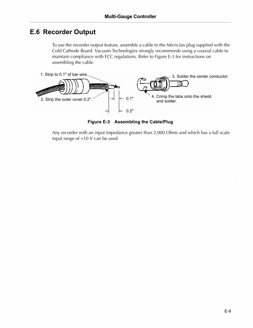
Multi-Gauge Controller
DR
AF
T 2
/6/0
4
E.6 Recorder Output
To use the recorder output feature, assemble a cable to the Micro Jax plug supplied with the Cold Cathode Board. Vacuum Technologies strongly recommends using a coaxial cable to maintain compliance with FCC regulations. Refer to Figure E-3 for instructions on assembling the cable.
Figure E-3 Assembling the Cable/Plug
Any recorder with an input impedance greater than 2,000 Ohms and which has a full scale input range of +10 V can be used.
2. Strip the outer cover 0.2".
3. Solder the center conductor.
4. Crimp the tabs onto the shield and solder.0.1"
0.2"
1. Strip to 0.1" of bar wire.
E-9
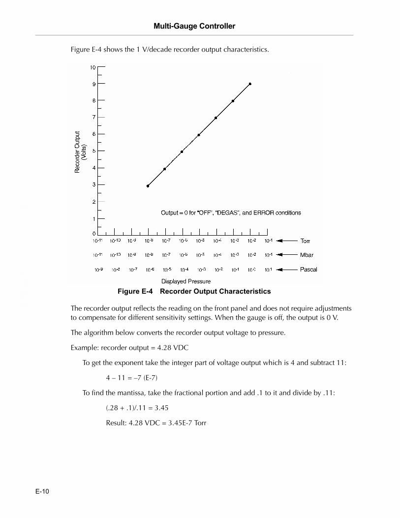
Multi-Gauge Controller D
RA
FT
2/6
/04
Figure E-4 shows the 1 V/decade recorder output characteristics.
Figure E-4 Recorder Output Characteristics
The recorder output reflects the reading on the front panel and does not require adjustments to compensate for different sensitivity settings. When the gauge is off, the output is 0 V.
The algorithm below converts the recorder output voltage to pressure.
Example: recorder output = 4.28 VDC
To get the exponent take the integer part of voltage output which is 4 and subtract 11:
4 – 11 = –7 (E-7)
To find the mantissa, take the fractional portion and add .1 to it and divide by .11:
(.28 + .1)/.11 = 3.45
Result: 4.28 VDC = 3.45E-7 Torr
E-10
Multi-Gauge Controller
DR
AF
T 2
/6/0
4
Appendix F. Remote I/O Board
The Remote I/O board (Part No. L8324301) enables Multi-Gauge remote operation without the use of an external computer and plugs into any one of the five positions in the mother board through low and high voltage pin and socket connectors. Optically-isolated inputs enable control of emission and degas functions for up to three ion gauges, and for keypad lockout. Relay contacts, also isolated, provide status outputs. External connections are made through the 37-pin, D-subminiature connector at the end of the card.
This appendix describes:
❑ Section F.1 “Specifications”
❑ Section F.2 “Installation” on page F-2
❑ Section F.3 “Operation” on page F-4
F.1 Specifications
Table F-1 Remote I/O Board Specifications
Specification Description
Electrical
Inputs Optically isolated and floatingLevel sensitive 3 to 32 VDC500 Ohms minimum to activate function current flows in the conventional manner: ❑ Into the + terminal ❑ Out of the � terminal
Outputs Relay contact, normally-open, gold-plated½ A at 24 VDC / 120 VAC
F-1

Multi-Gauge Controller D
RA
FT
2/6
/04
F.2 Installation
Use Table F-2, Table F-3 and Figure F-1 to understand the signal pin out pattern.
WARNING Any external wiring must conform to all applicable building and electrical codes to reduce the risk of shock and fire hazards.
CAUTION The contacts are gold-flashed making them suitable for logic level switching, but, application of AC or DC voltages greater than 20 V or 20 VA causes erosion of the gold, even in just one switching cycle.
NOTE Vacuum Technologies cannot guarantee compliance with FCC regulations for radiated emissions unless all external wiring is shielded with the shield terminated to the metal shroud on the D-sub connector. Secure the cable should to the connector with screws.
Table F-2 Input Function vs. Pin Number
Pin Number
Input Function + −
Keypad Lockout 9 10
EMIS 1 15 16
DEGAS 1 17 18
EMIS 2 7 8
DEGAS 2 19 37
EMIS 3 13 14
DEGAS 3 11 12
F-2

Multi-Gauge Controller
DR
AF
T 2
/6/0
4
Figure F-1 Pin Connector
Table F-3 Output Function vs. Pin Number
Pin Number
Output Function + −
System Status 4 3
EMIS 1 Status 30 31
DEGAS 1 Status 28 29
EMIS 2 Status 26 27
DEGAS 2 Status 24 25
EMIS 3 Status 22 23
DEGAS 3 Status 20 21
F-3

Multi-Gauge Controller D
RA
FT
2/6
/04
F.3 Operation
NOTE When powering up the Multi-Gauge, the eight output relays are momentarily activated for less than 100 msec before returning to the de-energized state.
F.3.1 Inputs
Refer to Table F-2 on page F-2:
Keypad Lockout Applying a voltage to the + and – terminals locks out the keypad except CHAN, and transfers control to the Remote I/O board. This input must be held active to continue control from the board. Once deactivated, all active functions turn off.
NOTE System parameters (SETPTS, EMIS MA, etc.) can only be programmed with this input inactive.
EMIS 1, 2, and 3 Activate these inputs to turn on emission for the first, second, and third ion gauge controllers, respectively (from the left, looking at the front of the unit). Conversely, deactivate these inputs to turn off emission.
DEGAS 1, 2, and 3 Activate these inputs to turn on the degas function, if present, for the first, second, and third ion gauge controllers, respectively (from the left, looking at the front of the unit). Degas cannot be active unless the emission is active. Deactivate these inputs to turn off degas.
F.3.2 Outputs
Refer to Figure F-3 on page F-3.
System Status Contacts close to indicate the absence of system faults.
EMIS 1, 2, and 3 Status Contacts close to indicate that emission is on for ion gauge 1, 2, or 3, respectively. Contacts open to indicate that emission is off.
DEGAS 1, 2, and 3 Status
Contacts close to indicate that the degas function, if any, for ion gauge 1, 2, or 3, respectively, is on. Contacts open to indicate that degas is off.
F-4

Multi-Gauge Controller
DR
AF
T 2
/6/0
4
Appendix G. Set Point Board
The Setpoint Board (Part No. L8327301 – Female; Part No. L8727302 – Male) plugs into any one of the five positions in the mother board through a low voltage connector and contains eight setpoint relays that are programmable through the Multi-Gauge unit. External connections are made through the 25-pin D-subminiature female/male connector at the edge of the board.
The required mating connector is a 25-pin D-subminiature plug with a metal shell and solder pins. One acceptable connector is Amphenol No. 747912-2, used in conjunction with Amphenol No. 205718 (cable clamp) and Amphenol No. 205980-4 (screw retainer kit).
After installation, place the SETPT label on the area provided at the rear of the unit to identify the card after the cover is installed.
Setpoints can be assigned to any of the installed gauges (channels). The setpoint trigger level and a hysteresis level are programmable. Hysteresis can be programmed to any level greater than or equal to the trigger level. It defaults to 10 percent above the setpoint level if not programmed.
This appendix describes:
❑ Section G.1 “Specifications”
❑ Section G.2 “Installation” on page G-2
❑ Section G.3 “Operation – Programming Setpoints” on page G-4
G.1 Specifications
Specifications are the same for both male and female connectors.
Setpoints 8, floating SPDT relays with NO, NC, and C terminals available
NOTE When powering up the Multi-Gauge, the eight setpoint relays are momentarily activated for less than 100 msec before returning to the de-energized state.
Contact Rating 3 A at 24 VDC / 250 VAC, gold-flashed
G-1

Multi-Gauge Controller D
RA
FT
2/6
/04
G.2 Installation
Installation depends on whether the connector is male or female.
G.2.1 Installation � Female
Use Table G-1 and Figure G-1 to connect the board.
Figure G-1 Female Connector Front View
Table G-1 Setpoint vs. Terminal Connections
Pin Number
Setpoint Number C NC NO
1 1 2 14
2 3 15 16
3 4 17 5
4 6 18 19
5 7 9 20
6 8 21 22
7 10 11 23
8 13 24 25
G-2

Multi-Gauge Controller
DR
AF
T 2
/6/0
4
G.2.2 Installation � Male
Use Table G-2 and Figure G-2 to connect the board.
Figure G-2 Male Connector Front View
Table G-2 Setpoint vs. Terminal Connections
Pin Number
Setpoint Number C NC NO
1 13 12 25
2 11 24 23
3 10 22 9
4 8 21 20
5 7 5 19
6 6 18 17
7 4 3 16
8 1 15 14
G-3

Multi-Gauge Controller D
RA
FT
2/6
/04
G.3 Operation � Programming Setpoints
Programming the setpoints is the same for both male and female connectors.
The setpoint relay is not energized until the pressure is below the setpoint trigger level. At this point, the normally-open contacts close and the number of the active setpoint appears on the front panel, even if it is not assigned to the channel shown. The setpoint relay remains energized until the pressure is greater than the hysteresis pressure level. At this point, the normally-open contacts open and the setpoint number on the front panel turns off.
NOTE Any external wiring must conform to all applicable building and electrical codes to reduce the risk of shock and fire hazards.
CAUTION The contacts are gold-flashed making them suitable for logic level switching, however, application of AC or DC voltages greater than 20 V or 20 VA causes erosion of the gold, even in just one switching cycle.
NOTE Vacuum Technologies cannot guarantee compliance with FCC regulations for radiated emissions unless all external wiring is shielded with the shield being terminated to the metal shroud on the D-sub connector. Secure the cable to the connector with screws.
G-4

Multi-Gauge Controller
DR
AF
T 2
/6/0
4
To program setpoints:
1. Press CHAN to select the channel for setpoint assignment.
2. Press SETPT.
SELECT SETPT appears on the front panel along with one or more of the numbers 1 through 8. The left-most available setpoint, or previously assigned setpoint, blinks on the front panel to act as a front panel cursor. Any numbers that appear to the right of the cursor were assigned previously. The number on the front panel is the setpoint trigger level. If the mantissa is 0.00, then that setpoint is available for assignment.
3. Enter a valid level to assign that setpoint to the channel shown.
4. Press the hysteresis key to show the hysteresis pressure level.
The default value is +10% of any newly-entered trigger level, but can be changed to any pressure level equal to or greater than the trigger level.
NOTE Consider the resolution and performance of the gauge that the setpoint is referenced to when selecting both the setpoint level and the hysteresis value. See suggested values in Table G-3.
❑ If no keys are pressed while the cursor is blinking, the front panel reverts back to reading pressure.
❑ If SETPT be pressed, it advances it to the next available or previously assigned setpoint.
To de-assign a setpoint, for example, to change channel assignments:
❑ Set the mantissa to 0.00. It is now available for use in some other channel.
Table G-3 Setpoint and Hysteresis Suggested Values
Gauge Minimum Setpoint Maximum Setpoint Minimum Hysteresis
Thermocouple or ConvecTorr 5 mTorr 700 mTorr 50% or 5 mTorr, whichever is greater
Capacitance Diaphragm Gauge 0.1% of full scale 100% of full scale 10% or lower
Ion Gauges � � 20%
G-5

Multi-Gauge Controller D
RA
FT
2/6
/04
This page intentionally left blank.
Multi-Gauge Controller
DR
AF
T 2
/6/0
4
Appendix H. Capacitance Diaphragm Gauge Board
The Capacitance Diaphragm Gauge Controller (CDG) Board (Part No. L6491301) operates standard and temperature-compensated transducers which require ±15 V up to 700 mA power and have an output signal of 0 to 10 VDC. Its pressure range (full scale) is selectable at 0.1, 1, 2, 10, 100, and 1000 Torr. Each board is capable of controlling two transducers, and up to two CDG boards can be installed for a total of four CDG transducers.
Since the total available output power of the board is 750 mA for each polarity, to avoid power overload errors, ensure that the power requirements of the transducers chosen for each board do not exceed that limit. This is only an issue with a few of the heated transducers which operate at 45 °C and above. Even in such cases, a combination of one high power and one unheated transducer per board, or two medium power heated transducers per board, is permissible.
The CDG board can be installed in any one of the five slots in the Multi-Gauge unit. However, since it is a high-profile board, Vacuum Technologies recommends that it be put into one of the three right-hand slots (as viewed from the front of the unit) for maximum flexibility. After installation, place the CDG label on the area provided at the rear of the unit to identify the board after the cover is installed.
This appendix describes:
❑ Section H.1 “Theory of Operation”
❑ Section H.2 “Specifications” on page H-2
❑ Section H.3 “Operation” on page H-4
H.1 Theory of Operation
Capacitance Diaphragm Gauges measure pressure by detecting the change in capacitance between two diaphragms which deflect due to a pressure differential. They are extremely accurate, 0.1 to 1% typical, and they measure true pressure (force per unit area) regardless of gas mixture. Full scale pressures of from 0.1 to 1000 Torr are available. These ranges are considered as the maximum obtainable, and at the far end of the range achieve tight accuracy only for short periods of time due to drift and repeatability errors. Accuracy loss at the far end of the range is mostly due to temperature variations, but is compensated in extended range transducers by heating the sensor to between 35 and 75 °C. An added benefit of a heated sensor is reduced condensation in the transducer. However, the heated sensor requires a longer warmup period to stabilize. Venting the system cools the sensor and requires restabilization unless an isolation valve is used.
H-1

Multi-Gauge Controller D
RA
FT
2/6
/04
H.2 Specifications
Table H-1 Specifications Capacitance Diaphragm Board
Specification Description
Software required Revision P2.1 or later
Input 0 to 10 VDC ± 500 mV
Impedance 10 kOhms
Accuracy Front panel readout within ± 0.2% of reading or 0.001% of full-scale, whichever is greater, of input signal. No zero offset.
Recorder output Buffered transducer output, into greater than 10 kOhms.Available at the transducer connectors.
Fault detection ❑ E11 � CDG power bad❑ E12 � Negative input within VAC range❑ E15 � Negative input out of VAC range. If the CDG input goes under range,
negative, the front panel flashes hyphens [- - -] to about �0.5 V, and then displays this code.
❑ E09 � Over pressure range. If the CDG input voltage go slightly over range, the front panel numbers flashes.
❑ E07 � Over temperature❑ E11 � Latches if any of the CDG power supplies are overloaded for more than
about one second, and requires either a keypad reset function or a Multi-Gauge basic unit POWER OFF/ON to clear and restore power.
For more information, refer to Section 3.2 �Error Codes� on page 3-1.
H-2

Multi-Gauge Controller
DR
AF
T 2
/6/0
4
Power supply Bipolar 15 VDC +5%, �3%; 750 mA max. per board, 700 mA max. per transducer.
Cable lengths Standard cables with lengths of 10, 25, 50, 75, and 100 feet are available from stock. Longer cables are available on special order. At the rear of the board, the top connector is CDG-A and the bottom is CDG-B (9-pin D-sub plug).
The pin-outs of the cable are as follows:❑ 1 � CDG(+)❑ 2 � RECORDER OUT❑ 3 � +15 V❑ 4 � +15 V❑ 5 � �15 V❑ 6 � �15 V❑ 7 � RECORDER GND❑ 8 � CDG(�)❑ 9 � POWER GND
Table H-1 Specifications Capacitance Diaphragm Board (Continued)
Specification Description
NOTE Do not connect the cable shield at the transducer end of the cable.
NOTE The top connector is CDG-A; the bottom connector is CDG-B. Refer to the specific CDG manufacturer’s instruction manual for color codes of the cable.
H-3

Multi-Gauge Controller D
RA
FT
2/6
/04
H.3 Operation
The correct software ROM must be installed in the Multi-Gauge basic unit. See the instructions provided with Multi-Gauge software upgrade kit. When the basic unit power is turned on and a CDG-based channel is selected using CHAN, AUX illuminates. For CDG-1A, AUX and 1 illuminate.
Press the CHAN button to cycle through:
❑ CDG-1B – AUX and 1 flash,
❑ CDG-2A – AUX and 2 flash, if installed, and so on.
The VAC button acts as a ZERO adjust (see Appendix H.3.1 “Zero Procedure”). The range of input for which this function works is intentionally limited to ± 400 mV, and the front panel reads zero for the voltage present when the VAC button is pressed. Although the front panel may show 0.00, it is possible to have an offset that is below the front panel resolution.
To determine if the offset exists:
❑ Press VAC.
The front panel goes blank and then reappears. If Multi-Gauge was able to zero the input, the front panel shows 0.00.
Before entering any calibration factors in the Multi-Gauge, let the transducer stabilize and calibrate. See the transducer manual for the recommended stabilization period. The calibration factor defaults to zero with a reset. For best accuracy and resolution, do the bulk of the ZERO adjustment at the transducer. Changing the CDG range cancels any internal offset.
In general, the pressure must be lowered to 1/10 of the CDG head’s lowest measurable pressure when zeroing. The default CDG range is 10 Torr.
To access the Range Select:
1. Press F.
2. Press SET PT/SENS.
This flashes a number in scientific notation, for example 1.00+1, which means that the full scale range is set to 10 Torr.
H-4

Multi-Gauge Controller
DR
AF
T 2
/6/0
4
3. Press the up and down arrow keys to cycle through ranges 0.1, 1, 2, 10, 100, and 1000 Torr. Changing the range selected cancels any previous zero settings, therefore the unit must be re-zeroed by pressing the VAC button.
At the completion of setting the full scale range, the front panel flashes the total decades of front panel range value. The Multi-Gauge default is 5.0, however, it should be set for the transducer in use. Use the UP or DOWN arrow keys to set the appropriate value.
❑ If set too high, zeroing the transducer becomes difficult.
❑ If set too low, the usable range is lost.
Table H-2 lists the appropriate value for Vacuum Technologies transducers. For other transducers, consult the manufacturer specifications.
H.3.1 Zero Procedure
The gauge can be zeroed after the CDG is installed and power has been applied for two to three hours.To zero out the head, the pressure in the vacuum system must an order of magnitude greater or less than the resolution of the CDG. Thus, for a 1 Torr full scale CDG, the lowest attainable reading would be 1 mTorr.
To zero this gauge:
1. Ensure that the pressure in the system is at least 1E-4 to 5E-5 Torr.
After stabilization in high vacuum, the zero pot on the CDG can be adjusted for a 0.000 mVDC reading.
2. Let the CDG stabilize and press VAC.
A 0.00 reading should occur.
The CDG is now zeroed.
Vacuum Technologies CeramiCel: 4 decades
MKS's Baratron: 4 decades
Table H-2 Vacuum Technologies Transducer Recommended Values
Maximum Minimum (Resolution Limit)
1000 Torr .1 Torr (100 mTorr)
100 Torr .01 Torr (10 mTorr)
10 Torr .001 Torr (1 mTorr)
1 Torr .0001 Torr (.1 mTorr)
H-5

Multi-Gauge Controller D
RA
FT
2/6
/04
This page intentionally left blank.

Multi-Gauge Controller
DR
AF
T 2
/6/0
4
Appendix I. Convectron Board
The Convectron board contains all the circuitry required to operate four Convectron® 275-type gauge tubes. It can be installed in any one of the five slots in the Multi-Gauge basic unit. After installation, place the CONV label on the area provided at the rear of the unit to identify the board after the cover is installed. Up to two Convectron boards can be installed for a total of eight available Convectron tubes.
Because the Convectron board uses the same thermocouple front panel annunciators as the Thermocouple (TC) Board (part number L6430301), the combination of Convectron and Thermocouple boards cannot exceed two. If one of each board is installed, the front panel does not indicate which Thermocouple readings correspond to a Convectron.
This appendix describes:
❑ Section I.1 “Convectron Principles of Operation”
❑ Section I.2 “Specifications” on page I-2
❑ Section I.3 “Installation” on page I-2
❑ Section I.4 “Operation” on page I-4
I.1 Convectron Principles of Operation
The response of the Convectron is affected by factors other than pressure. Normally, the tube is calibrated for nitrogen or air. If the residual gas in the vacuum system is some other gas, the pressure reading may be affected. For example, hydrogen and helium conduct heat away from the tube more rapidly than air, leading to a pressure reading that is higher than the actual pressure. Contaminants such as oil, dust, and other chemicals can change the surface of the tube and heater which, in turn, change the ability of the tube to dissipate the heat and affect the pressure reading.
Because the Convectron gauge tube is a thermal response device, the ability of the tube to respond to abrupt pressure changes is limited by the mass of the sensor wire in the tube. If this combination is very small, the tube responds more rapidly than a tube with larger wire sizes.
In general, Convectron gauge tubes are used to gain an indication of the vacuum in a system rather than an accurate measure. So many factors can affect the output of the tube that unless special care and precautions are taken, the pressure read on the control is usually only accurate to within ±30% of the indicated reading.
I-1

Multi-Gauge Controller D
RA
FT
2/6
/04
I.2 Specifications
I.3 Installation
To install the tube and wire the board:
1. Position Convectron gauge tubes on the vacuum system so that contaminants do not collect in the tube.
Mount the tube horizontally (Figure I-1) to prevent oil build up in the tube from mechanical pumps, and to read pressure above 1 Torr.
Figure I-1 Mounting the Convectron Tube
Table I-1 Specifications Convectron Board
Specification Description
Software required Revision P2.3 or later
Pressure range 760 Torr to 1 x 10⁻⁴ Torr
Cable length Standard cables with lengths of 10, 25, 50, 75, and 100 feet are available from stock.Longer cables are available on special order (Table I-3). Connections are made to the rear of the board.
Fault Detections E03 � No cable or open sensor; shorted sensor.E07 � Overtemperature
Recorder output 0 to 7 V linear (1 V per decade). See Table I-2 for wiring connections.Vacuum Technologies recommends the use of shielded wiring to maintain compliance with FCC regulations for radiated emissions. The recorder output reflects ATM and VAC settings.
I-2
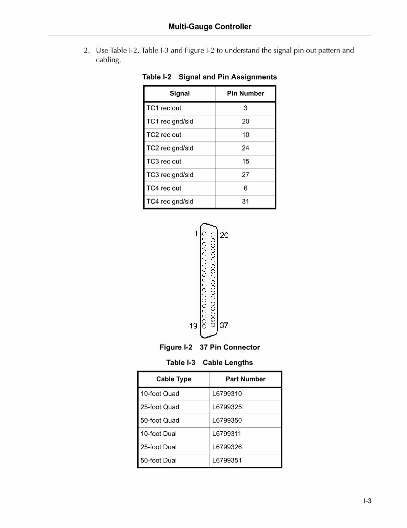
Multi-Gauge Controller
DR
AF
T 2
/6/0
4
2. Use Table I-2, Table I-3 and Figure I-2 to understand the signal pin out pattern and cabling.
Figure I-2 37 Pin Connector
Table I-2 Signal and Pin Assignments
Signal Pin Number
TC1 rec out 3
TC1 rec gnd/sld 20
TC2 rec out 10
TC2 rec gnd/sld 24
TC3 rec out 15
TC3 rec gnd/sld 27
TC4 rec out 6
TC4 rec gnd/sld 31
Table I-3 Cable Lengths
Cable Type Part Number
10-foot Quad L6799310
25-foot Quad L6799325
50-foot Quad L6799350
10-foot Dual L6799311
25-foot Dual L6799326
50-foot Dual L6799351
I-3

Multi-Gauge Controller D
RA
FT
2/6
/04
I.4 Operation
Multi-Gauge indicates the presence of the Convectron board by illuminating the curved bar graph. The Convectron shown is identified by the Thermocouple number just beneath the bar graph. The Convectron reading appears on the main digital front panel when there are no annunciators lit. Multi-Gauge provides the capability to select any one of the installed thermocouples on the bar graph simultaneously with a main ion gauge, such as a UHV or Bayard-Alpert gauge, using the up or down arrows. This causes the Thermocouple identifier to scroll through the installed Convectrons.
If two Convectron boards are installed in the basic unit, Multi-Gauge assigns the identification TC1, TC2, TC3, and TC4 to the left-most installed Convectron board (as viewed from the front of the unit), and TC5, TC6, TC7, and TC8 to the right-most installed board.
Further aspects of operation include:
❑ Section I.4.1 “Calibration”
❑ Section I.4.2 “Auto Turn-on”
I.4.1 Calibration
Before using the Convectron board for pressure measurements, set the atmosphere and vacuum readings:
1. Press CHAN to set the atmosphere reading by selecting the desired Convectron tube.
2. Ensure that the tube is exposed to atmospheric pressure.
3. Press ATM.
The front panel reads 760 Torr, or the equivalent in mBar or Pascal, as desired.
4. Press CHAN to set the vacuum reading by selecting the desired Convectron.
5. Expose the selected Convectron to a vacuum level lower than 10−4 Torr or mBar (10−2 Pascal).
6. Press VAC.
The front panel reads 1.0 x 10⁻⁴ Torr. The Convectron tube is now calibrated.
NOTE ❑ If the tube has been at atmosphere and readings in the 10−4 Torr range are required, expose the tube to a vacuum of less than 10−4 for at least 15 minutes and calibrate it to vacuum through the preceding steps. Readings through the 10−4 Torr range are then possible.
❑ Since the Multi-Gauge calibrates the Convectron to any ATM or VAC setting, make sure that these functions are applied accurately.
I-4
Multi-Gauge Controller
DR
AF
T 2
/6/0
4
I.4.2 Auto Turn-on
Using a Convectron board in conjunction with an ion gauge board enables the programming of a Convectron to automatically turn on the emission for an ion gauge. The AUTO-ON feature allows programming of the turn-on level between 1 x 10⁻³ Torr and 5 x 10⁻³ in Torr or mBar units (1 x 10⁻¹ to 5 x 10⁻¹ in Pascal) for all Vacuum Technologies ion gauges. The Model 564 and 580 Broad Range Bayard-Alpert gauges can also be set to turn on between 1 x 10⁻² and 5 x 10⁻² Torr or mBar (1 x 100 and 5 x 100 Pascal).
To program AUTO-ON:
1. Press CHAN to select the desired ion gauge.
2. Press AUTO-ON.
SELECT AUTO-ON illuminates along with the number of the first available Convectron or the number of a previously assigned Convectron. The front panel shows a pressure setting, if assigned, or 0.00 mantissa if not assigned.
3. Press AUTO-ON to select the next available Convectron or to exit to the pressure.
4. Set the actual turn-on pressure.
To cancel the Auto turn-on, set the mantissa to 0.00.
Once all flashing digits are set, AUTO-TURN ON programming is complete.
When Auto Turn-On is enabled for a given ion gauge, EMIS can still be used to turn off the ion gauge. Turning off the ion gauge with EMIS disables the Auto Turn-On setting and requires the AUTO-ON programming routine to re-activate the AUTO-ON setting.
NOTE Every Convectron is available as a turn-on source, regardless of whether it has a setpoint assigned to it or whether it has been assigned to turn on another ion gauge.
I-5

Multi-Gauge Controller D
RA
FT
2/6
/04
Figure I-3 Granville Phillips/275 Convectron with Multi-Gauge Recorder Output
I-6

Multi-Gauge Controller
DR
AF
T 2
/6/0
4
Appendix J. Inverted Magnetron Board
The Multi-Gauge Inverted Magnetron Board (Part No. L9066301) operates the Inverted Magnetron Gauge (IMG) with cable lengths of up to 100 feet. Its operating voltage is +3 kV and its nominal sensitivity is 2.7 A/Torr. The use of software linearization and dynamic power modulation allow a useful range of 1 x 10⁻³ to 1 x 10⁻¹¹ Torr.
WARNING Inverted Magnetron Gauges require the use of a high voltage source which can be lethal. Proper grounding of the Multi-Gauge unit and the gauge head are necessary. Use extreme caution when working with these instruments. The instrument must be operated only by properly trained personnel. Do not operate the Multi-Gauge with the cover off. Ensure that the ground wire on the gauge cable is properly attached to the rear panel grounding post on the unit.
The IMG board can be installed in any one of the five slots in the Multi-Gauge unit, however, since it is a high-profile board, Vacuum Technologies recommends that it be put into one of the three right-hand slots (as viewed from the front of the unit) for maximum flexibility. After installation, place the IMG label on the area provided at the rear of the unit to identify the card after the cover is installed.
This appendix describes:
❑ Section J.1 “Theory of Operation”
❑ Section J.2 “Installation”
❑ Section J.3 “Calibration and Adjustments” on page J-5
❑ Section J.4 “Inverted Magnetron Board Operation” on page J-5
❑ Section J.5 “Recorder Output” on page J-8
J-1

Multi-Gauge Controller D
RA
FT
2/6
/04
J.1 Theory of Operation
The inverted magnetron gauge is often used in ultra-high vacuum applications that are unsuitable for hot filament vacuum gauges due to process chemistry or high ambient x-ray levels. The operating principle of the IMG is similar to a magnetron cold cathode gauge, such that ions are trapped by a high voltage electromagnetic field and collected at an electrode. Ionization in the gauge cavity is initiated by cosmic rays or stray radioactivity striking the electrodes to release secondary electrons. These secondary electrons strike ambient gas molecules, creating positive ions. The electrons released as a result of these collisions propagate additional ionization due to their long helical paths in the gauge’s magnetic field.
In contrast to the traditional magnetron cold cathode design, the IMG anode is a rod centered and aligned along the longitudinal axis of the gauge. A potential of approximately 3 kV is generated between the anode and the cylindrical cathode, which collects ions. The IMG design addresses the main drawback of the cold cathode gauge: the inability to start discharge at low pressures. The Vacuum Technologies IMG has demonstrated starts as low as 10−9 Torr.
The Multi-Gauge Inverted Magnetron Control Board allows readings from 1 x 10⁻³ Torr to 5 x 10⁻¹¹ Torr. The ion current collected at the cathode is proportional to pressure such that the nominal gauge sensitivity is 2.7 A/Torr.
J-2
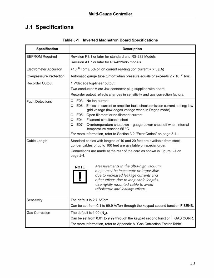
Multi-Gauge Controller
DR
AF
T 2
/6/0
4
J.1 Specifications
Table J-1 Inverted Magnetron Board Specifications
Specification Description
EEPROM Required Revision P3.1 or later for standard and RS-232 Models.Revision A1.7 or later for RS-422/485 models.
Electrometer Accuracy >10−6 Torr ± 5% of ion current reading (ion current = > 5 µA)
Overpressure Protection Automatic gauge tube turnoff when pressure equals or exceeds 2 x 10⁻² Torr.
Recorder Output 1 V/decade log-linear output. Two-conductor Micro Jax connector plug supplied with board.Recorder output reflects changes in sensitivity and gas correction factors.
Fault Detections ❑ E03 � No ion current❑ E06 � Emission current or amplifier fault, check emission current setting; low
grid voltage (low degas voltage when in Degas mode) ❑ E05 � Open filament or no filament current❑ E04 � Filament circuit/cable short❑ E07 � Overtemperature shutdown � gauge power shuts off when internal
temperature reaches 65 °C.For more information, refer to Section 3.2 �Error Codes� on page 3-1.
Cable Length Standard cables with lengths of 10 and 20 feet are available from stock. Longer cables of up to 100 feet are available on special order. Connections are made at the rear of the card as shown in Figure J-1 on page J-4.
Sensitivity The default is 2.7 A/Torr. Can be set from 0.1 to 99.9 A/Torr through the keypad second function F SENS.
Gas Correction The default is 1.00 (N2). Can be set from 0.01 to 9.99 through the keypad second function F GAS CORR.For more information, refer to Appendix A �Gas Correction Factor Table�.
NOTE Measurements in the ultra-high vacuum range may be inaccurate or impossible due to increased leakage currents and other effects due to long cable lengths. Use rigidly mounted cable to avoid tribolectric and leakage effects.
J-3

Multi-Gauge Controller D
RA
FT
2/6
/04
J.2 Installation
The IMG tube operates in any orientation. Because there is a strong magnetic field around the tube, when near other magnetic materials, handle the tube with great care. Tube positioning on a vacuum system is very important if dependable readings are to be obtained.
To install:
1. Locate the port as close to the region of measurement as possible, obeying the following rules:
❑ Avoid locations near the inlets to high-vacuum pumps.
❑ Since the gas discharge in the tube breaks down hydrocarbons causing contamination of the gauge tube, make sure the tube is protected from direct exposure to mechanical and diffusion pump fluids.
❑ If the port is near or facing cryogenic surfaces, note that the apparent pressure reading will be significantly lower than actual pressure.
2. Use Figure J-1 to connect the board.
Figure J-1 Card Connections
J-4

Multi-Gauge Controller
DR
AF
T 2
/6/0
4
For further discussion on the theory and operation of cold cathode gauge vacuum measurement, use the following references:
❑ Dushman, S., Lafferty, J.M., SCIENTIFIC FOUNDATIONS OF VACUUM TECHNIQUE, John Wiley & Sons, Inc., Second Edition, New York, 1962
❑ Guthrie, A., VACUUM TECHNOLOGY, John Wiley & Sons, Inc., 1963
❑ Lewin, G., VACUUM SCIENCE AND TECHNOLOGY, McGraw-Hill, New York, 1965
❑ Redhead, P.A. et al, ULTRAHIGH VACUUM, Chapman and Hall, London, 1968.
J.3 Calibration and Adjustments
The system automatically self-calibrates to compensate for component variations with temperature and time.
J.4 Inverted Magnetron Board Operation
Multi-Gauge indicates the presence of an Inverted Magnetron Gauge card by illuminating CC when the channel into which the card is plugged is selected using CHAN. On initial power up, the front panel shows OFF, indicating that the gauge is not measuring pressure.
To measure pressure:
1. Ensure that the cable and gauge head are properly connected and CC illuminates.
2. Press EMIS to toggle the high voltage source.
When a valid pressure measurement is available, it appears.
Error code indications include:
❑ If the current measurement is zero, the Multi-Gauge assumes first that the pressure is near the under pressure limit and that there is difficulty in starting the gauge. Hyphens [- - -] appear for approximately 30 seconds while an attempt is made to fire the gauge. If no gauge current is sensed during that time, the error code E13 (insufficient signal) appears and shuts off. This might also indicate an open cable.
❑ If the pressure drops below 1 x 10⁻¹¹ Torr after the initial start-up period, the gauge shuts off with an error code of E12 (under pressure). Any setpoints assigned to that cold cathode de-energize. The fault must be cleared before the cold cathode can be re-started.
❑ If the ion current is excessively high, either E09 (over pressure) or E04 (over current) appear, as a possible indication of a shorted cable or excessive gauge contamination.
❑ Other possible error codes are E07 (over temperature) and E11 (power supply error).
J-5

Multi-Gauge Controller D
RA
FT
2/6
/04
To stop measuring pressure:
❑ Press EMIS. EMIS goes off and the front panel shows OFF to indicate that the gauge has been shut off. Pressing the EMIS button also removes any error messages from the front panel and emission can be retried.
Other operational issues include:
❑ Section J.4.1 “Operation at High Pressure”
❑ Section J.4.2 “Starting at Low Pressure” on page J-6
❑ Section J.4.3 “Gauge Tube Maintenance” on page J-7
❑ Section J.4.4 “Troubleshooting” on page J-7
J.4.1 Operation at High Pressure
If the gauge is left on for a few hours in the pressure range of 10−3 to 10−2 Torr, cathode sputtering may require frequent recalibration and maintenance. This problem is not severe for short periods of operation.
Rapid venting of the tube to the atmosphere does not cause damage to the tube or gauge control. The gauge tube discharge extinguishes at a pressure of 2 x 10⁻² Torr. Exposure of the gauge tube to atmospheric pressure with the control on is not harmful to the tube.
J.4.2 Starting at Low Pressure
When the gauge has been off for a period of time with the system pressure of 10−9 Torr or lower, delayed starting may occur. This no-strike condition is caused by the lower probability, at the lower pressure, of ionizing enough atoms and/or molecules to obtain the starting glow discharge condition. The indications for this are an off-scale hyphen [- - -] reading. This is not a problem in systems which are periodically cycled to air, since the gauge can be turned on in the higher pressure portion of the cycle. Once started, the gauge does not extinguish at any pressure within its operating range. If a no-strike condition persists for more than a few minutes, the gauge can be started by increasing the pressure in the system.
J-6

Multi-Gauge Controller
DR
AF
T 2
/6/0
4
J.4.3 Gauge Tube Maintenance
The gauge tube requires periodic maintenance. Leaving the gauge inactive for sustained periods of time or exposing it to system contaminants such as pump oil can cause gas absorption into its metal surfaces, and in turn, faulty readings and slow starting.
One method of cleaning up the gauge tube is to apply heat to the gauge. This process drives the absorbed gases off the walls and surfaces of the gauge. The Inverted Magnetron Gauge tube is bakeable to 250 °C assuming the connection to the vacuum system is also bakeable. Vacuum Technologies cables L9064 and R0341 are bakeable to 250 °C.
For best results and for removing built-up contaminants, a thorough cleaning of the gauge tube anode and the cathode surfaces is necessary.
To do this:
1. Disassemble the gauge and clean each part using a wire brush, steel wool, or emery cloth.
2. Wash parts in soap and water (preferably Alconox), rinse in plain water, do a final rinse in alcohol, then hot-air dry if possible.
Internal parts which are damaged or excessively contaminated can be replaced by ordering the Inverted Magnetron Maintenance Kit (Part No.R0040301).
J.4.4 Troubleshooting
Table J-2 lists some troubleshooting tips.
Table J-2 Inverted Magnetron Troubleshooting
Fault Possible Cause/Remedy
Gauge control does not read above 1 x 10⁻¹¹ Torr � E03
Check the high voltage cable connection at tube and rear of control.
Gauge control reads E09 (over pressure) even when pressure is below 1 x 10⁻² Torr
Check high voltage cable for a short to the center conductor.Inspect gauge tube for a low resistance from cathode to body. Check for insulator damage.
Gauge tube will not strike a discharge Check the LED mounted on the top side of the cold cathode board (visible without removing the basic unit cover). If it is lit, the high voltage power supply is working.Check high voltage cable for continuity.The system pressure may be too low (E13) for the gauge tube to strike.
Reading on gauge control is erratic Follow procedure for disassembly and cleaning of the tube if the gauge tube is contaminated.
J-7
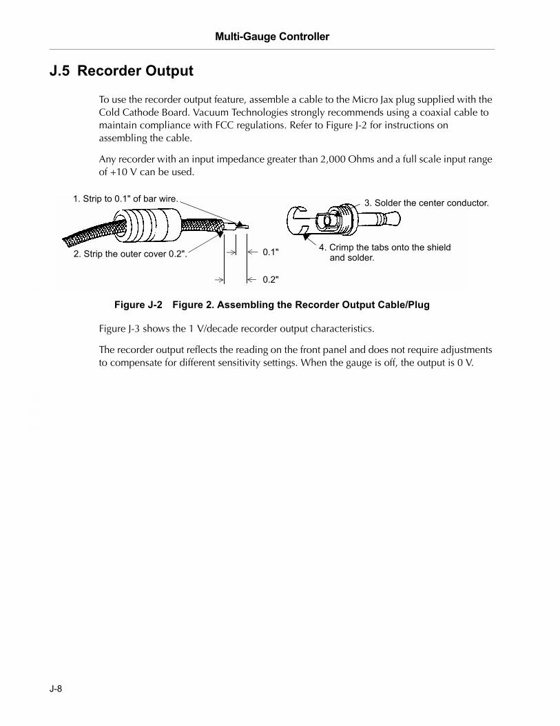
Multi-Gauge Controller D
RA
FT
2/6
/04
J.5 Recorder Output
To use the recorder output feature, assemble a cable to the Micro Jax plug supplied with the Cold Cathode Board. Vacuum Technologies strongly recommends using a coaxial cable to maintain compliance with FCC regulations. Refer to Figure J-2 for instructions on assembling the cable.
Any recorder with an input impedance greater than 2,000 Ohms and a full scale input range of +10 V can be used.
Figure J-2 Figure 2. Assembling the Recorder Output Cable/Plug
Figure J-3 shows the 1 V/decade recorder output characteristics.
The recorder output reflects the reading on the front panel and does not require adjustments to compensate for different sensitivity settings. When the gauge is off, the output is 0 V.
2. Strip the outer cover 0.2".
3. Solder the center conductor.
4. Crimp the tabs onto the shield and solder.0.1"
0.2"
1. Strip to 0.1" of bar wire.
J-8

Multi-Gauge Controller
DR
AF
T 2
/6/0
4
Figure J-3 Figure 3. Recorder Output Characteristics
The algorithm below converts the recorder output voltage to pressure.
Example: recorder output = 4.28 VDC
To get the exponent take the integer part of voltage output which is 4 and subtract 11:
4 – 11 = –7 (E-7)
To find the mantissa, take the fractional portion and add .1 to it and divide by .11:
(.28 + .1)/.11 = 3.45
Result: 4.28 VDC = 3.45E-7 Torr
J-9

Multi-Gauge Controller D
RA
FT
2/6
/04
This page intentionally left blank.

Multi-Gauge Controller
DR
AF
T 2
/6/0
4
Appendix K. ConvecTorr Board
The ConvecTorr Printed Circuit Control Board (Part No. L9887301) contains all the circuitry required to operate two ConvecTorr gauge tubes. It can be installed in any one of the five slots in the Multi–Gauge basic unit. After installation, place the Thermocouple label on the area provided to identify the card after the cover is installed. Up to two ConvecTorr cards can be installed for a total of four available ConvecTorr gauges.
This appendix describes:
❑ Section K.1 “Principle of Operation”
❑ Section K.2 “Specifications” on page K-2
❑ Section K.3 “Operation” on page K-3
❑ Section K.4 “Calibration” on page K-3
❑ Section K.5 “Auto Turn-on” on page K-4
❑ Section K.6 “Recorder Output” on page K-5
K.1 Principle of Operation
This section discusses:
❑ Section K.1.1 “Traditional Thermocouple Theory”
❑ Section K.1.2 “The ConvecTorr” on page K-2
K.1.1 Traditional Thermocouple Theory
A thermocouple operates on the principle that, at sufficiently low pressures, the thermal conductivity of the gas decreases with a decrease in pressure. A thermocouple is attached to a heater wire in which the temperature is raised to approximately 350 °C by passing a current through the wire. When constant power is maintained through the heater wire, the temperature measured by the thermocouple changes with pressure. This change is directly related to the heat conducted away by the gas in the environment. The electromotive force (emf) measured from the thermocouple is read on a scale which has been calibrated for pressure.
K-1

Multi-Gauge Controller D
RA
FT
2/6
/04
K.1.2 The ConvecTorr
The design approach provides the faster-than-thermocouple response of the pirani, while avoiding problems incurred by the a long, thin, and fragile pirani filament. The ConvecTorr circuitry measures the amount of current required to keep the thermocouple junction at a constant temperature as opposed to conventional thermocouples that measure the (output voltage) temperature of the element junction at a fixed current. Controlling and measuring the current provides a faster response time, typically .3 of a second, as compared to standard a thermocouple which has a 1.5 second response.
The response of the ConvecTorr is also affected by factors other than pressure. Normally, the tube is calibrated for nitrogen or air. If the residual gas in the vacuum system is some other gas, the pressure reading may be affected. For example, hydrogen and helium, lighter weight gases, conduct the heat away from the thermocouple more rapidly than air, leading to a reading which is higher than the actual pressure. Heavier weight gas compositions like argon conduct heat away at a slower rate, indicating a lower pressure than the actual pressure. Contaminants such as oil, dust, and other chemicals can change the surface of the thermocouple and heater which, in turn, changes the ability of the thermocouple junction to dissipate the heat and affects the pressure reading.
ConvecTorr gauge tubes should be positioned on the vacuum system so that contaminants do not collect in the tube. Preferably, orient the tube port down to prevent contaminants from building up in the tube.
K.2 Specifications
Table K-1 ConvecTorr Board Specifications
Specification Description
EEPROM required Revision P3.1 or later for standard and RS-232 Models.Revision A1.7 or later for RS-422/485 models
Software requirement 3.1 or higher
Range 760 Torr to 1 mTorr
Response 1 sec typical
Accuracy ±10% or 1 mTorr, whichever is greater (typical)
Recorder output Log/linear 1-7 VDC
Cable lengths Standard lengths available � 10, 25, 50, 75 and 100 feetCustom lengths are also available
Fault Detection E03 � No cable connection, possible open circuit for heater or thermocouple junction on the ConvecTorr gauge tube
K-2
Multi-Gauge Controller
DR
AF
T 2
/6/0
4
K.3 Operation
The Multi–Gauge indicates the presence of the ConvecTorr card by illuminating the curved bar graph. The ConvecTorr shown is identified by the Thermocouple number beneath the bar graph. The Convectorr reading also appears on the front panel when there are no annunciators lit. Multi-Gauge also provides the capability to select any one of the installed Thermocouples on the bar graph simultaneously with a main ion gauge, such as a UHV or Bayard-Alpert gauge, by using the up or down arrows. This causes the Thermocouple identifier to scroll through the installed ConvecTorr gauges. If two ConvecTorr cards are installed in the basic unit, Multi-Gauge assigns the identification TC1 and TC2 to the left-most installed ConvecTorr card (as viewed from the front of the unit) and TC3 and TC4 to the right-most installed card.
K.4 Calibration
Before using the ConvecTorr card for pressure measurements, set the atmosphere and vacuum readings.
To do this:
1. Press CHAN to select the desired thermocouple.
2. Ensure that the ConvecTorr gauge tube is exposed to atmospheric pressure.
3. Press ATM.
The front panel reads 760 Torr, or the equivalent in mbar or Pascal, as desired.
4. Press CHAN and select the desired ConvecTorr gauge tube.
5. Expose the selected ConvecTorr gauge tube to a known vacuum level as high as 9.9 x 10⁻² Torr or mbar (9.9 x 100 Pascal) or to a vacuum level lower than 10−3 Torr or mbar (10−1 Pascal).
6. Press VAC.
The front panel shows the most recent vacuum setting, initially 1.0 x 10⁻³ Torr, with the most significant digit flashing.
7. Set the front panel to the vacuum level desired.
The ConvecTorr gauge tube is now calibrated.
K-3

Multi-Gauge Controller D
RA
FT
2/6
/04
K.5 Auto Turn-on
Using a ConvecTorr card in conjunction with an ion gauge card enables the programming of a ConvecTorr to automatically turn on emission for an ion gauge. The AUTO-ON feature allows programming of the turn-on level between 1 x 10⁻³ Torr and 5 x 10⁻³ in Torr or mbar units (1 x 10⁻¹ to 5 x 10⁻¹ in Pascal) for all Vacuum Technologies ion gauges. The Vacuum Technologies Model 564 Broad Range Bayard-Alpert gauge can also be set to turn on between 1 x 10⁻² and 5 x 10⁻² Torr or mbar (1 x 100 and 5 x 100 Pascal).
To program AUTO-ON:
1. Press CHAN and select the ion gauge for automatic turn on.
2. Press AUTO-ON.
SELECT AUTO-ON illuminates along with the number of the first available thermocouple or the number of a previously assigned thermocouple. The front panel shows a pressure setting if assigned or 0.00 mantissa if not assigned.
3. Press AUTO-ON again to select the next available thermocouple or exit to the pressure front panel.
4. Change the flashing digit values to set the turn-on pressure.
To cancel the Auto turn-on, set the mantissa to 0.00.
Once all flashing digits are set, AUTO-TURN ON programming is complete.
NOTE When the Auto Turn-On is enabled for a given ion gauge, EMIS can still be used to turn off the ion gauge. Turning off the ion gauge with EMIS disables the Auto Turn-On setting and requires the Auto-On programming routine to re-activate the Auto-On setting.
NOTE ❑ Since the Multi–Gauge calibrates the thermocouple to any ATM or VAC setting, the user is responsible for applying these functions accurately.
❑ Every thermocouple is available as a turn-on source, regardless of whether it has a setpoint assigned to it or whether it has been assigned to turn on another ion gauge.
K-4
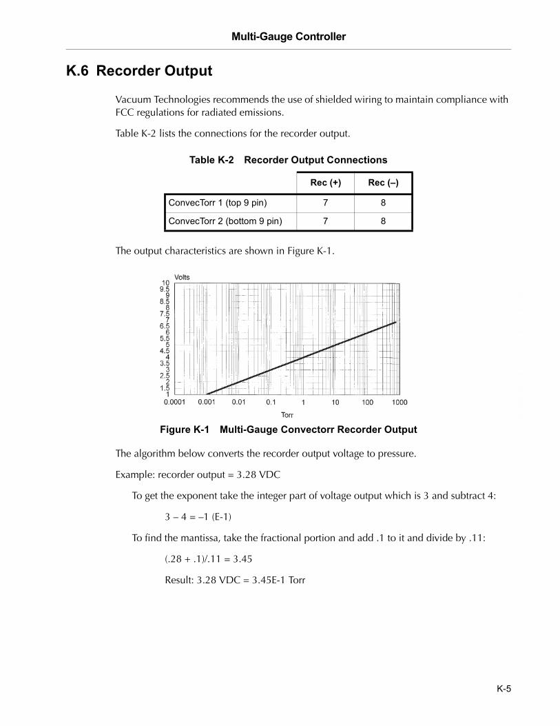
Multi-Gauge Controller
DR
AF
T 2
/6/0
4
K.6 Recorder Output
Vacuum Technologies recommends the use of shielded wiring to maintain compliance with FCC regulations for radiated emissions.
Table K-2 lists the connections for the recorder output.
The output characteristics are shown in Figure K-1.
Figure K-1 Multi-Gauge Convectorr Recorder Output
The algorithm below converts the recorder output voltage to pressure.
Example: recorder output = 3.28 VDC
To get the exponent take the integer part of voltage output which is 3 and subtract 4:
3 – 4 = –1 (E-1)
To find the mantissa, take the fractional portion and add .1 to it and divide by .11:
(.28 + .1)/.11 = 3.45
Result: 3.28 VDC = 3.45E-1 Torr
Table K-2 Recorder Output Connections
Rec (+) Rec (�)
ConvecTorr 1 (top 9 pin) 7 8
ConvecTorr 2 (bottom 9 pin) 7 8
K-5

Multi-Gauge Controller D
RA
FT
2/6
/04
This page intentionally left blank.

Multi-Gauge Controller
DR
AF
T 2
/6/0
4
Appendix L. RS232 and RS485/422 Boards, and ASCII Protocol Option
Part No. L6439301 (RS232 Interface), Part No. L6449301 (Fiber Optic RS232 Interface), Part No. L8940301 (RS485/422 Interface)
The Vacuum Technologies ASCII protocol applies to both the RS232 option and the RS485/422 option. Software version Ax.x is required.
L.1 RS232
Two RS232 interface options are available for Multi-Gauge: standard EIA-232 hardware compatible interface and fiber optic interface. Both of these PCB options plug into the dedicated digital communications interface slot (J3) on the basic unit mother board, though only one can be installed at a time.
The RS232 board contains two DIP switches to configure the board for different mother board revisions and to perform a null modem function, for example, swapping the Rxd, Txd, CTS, and RTS connections. Set these items before the board is installed into the unit. Factory settings configure for use as a null modem (see Table L-1 and Table L-2).
Table L-1 Connection Configurations
Connections S1-1 S1-2 S1-3 S1-4 S1-5 S1-6 S1-7 S1-8
RTS at pin 7CTS at pin 8
CL OP CL OP NULL
RTS at pin 8CTS at pin 7
OP CL OP CL STRAIGHT
Txd at pin 3Rxd at pin 2
CL OP CL OP NULL
Txd at pin 2Rxd at pin 3
OP CL OP CL STRAIGHT
Table L-2 Mother Board Revisions
Revision S2-1 S2-2 S2-3 S2-4
V or earlier OP OP OP OP
W or later CL CL CL CL
L-1

Multi-Gauge Controller D
RA
FT
2/6
/04
For switches labeled ON or OFF: CL = ON, OP = OFF
NOTE Revision V or earlier mother boards can be easily identified by the presence of a black box mounted near the power entry connector of the basic unit and attached by Velcro to a capacitor on the mother board.
The fiber optic board uses a Hewlett-Packard HFBR-2502/1502 receiver and transmitter pair to implement a low cost fiber link. This is useful in electrically noisy environments, to eliminate ground loops, or when the Multi-Gauge unit must be at a different voltage potential than the host computer such as high-energy physics applications.
L.1.1 Specifications
Consult the host computer instruction manual for its serial port connections.
Multi-Gauge outputs:
❑ +9 V for an asserted (logic 0) level
❑ –9 V for an unasserted (logic 1) level
Input signals to Multi-Gauge must be between:
❑ +2.4 V and +30 V for an asserted (logic 0) level
❑ +0.8 V and –30 V for an unasserted (logic 1) level
NOTE Vacuum Technologies cannot guarantee compliance with FCC regulations for radiated emissions unless all external wiring is shielded, with the shield being terminated to the metal shroud on the D-sub connector. Secure the cable to the connector with screws.
Table L-3 RS232 Driver Board Multi-Gauge Port Signal Specifications
Pin Signal Description
5 Ground
3, 2 TXD Transmitted Data � outputs serial data from the Multi-Gauge to the host RXD line.
2, 3 RXD Received Data � inputs serial data to the Multi-Gauge from the host TXD line.
7, 8 RTS Not used.
4 DTR Data Terminal Ready � output signal from the Multi-Gauge. Set to logic 0 when Multi-Gauge is powered up and, therefore, ready to communicate.
L-2

Multi-Gauge Controller
DR
AF
T 2
/6/0
4
L.1.2 RS232 Installation
To install RS232 board:
1. Ensure that the Multi-Gauge is turned off and the power cable disconnected.
2. Remove the top cover (see Table L-1 on page L-3).
3. Remove and save the small screws and discard the blank plastic hole cover on the rear panel.
NOTE It may be necessary to remove plug-in boards to access connector J3 on the mother board. Both option boards make use of connector J3, however, only one option can be installed at a time.
Figure L-1 Cable Installation
L-3
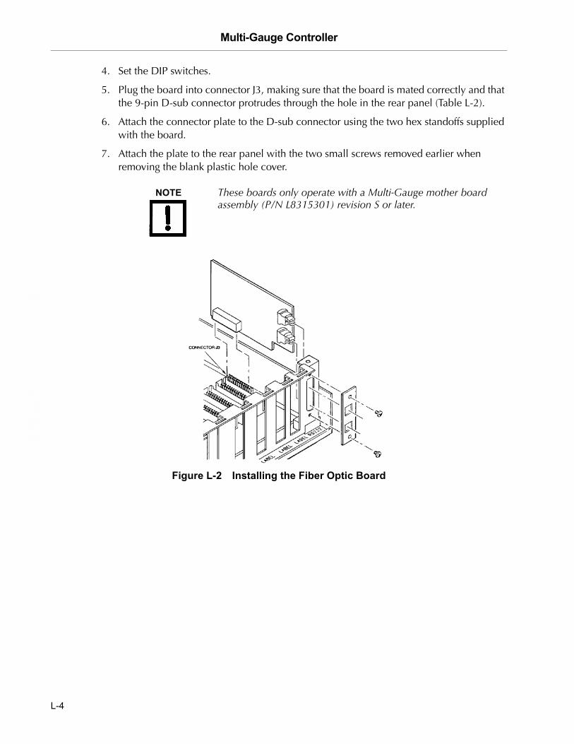
Multi-Gauge Controller D
RA
FT
2/6
/04
4. Set the DIP switches.
5. Plug the board into connector J3, making sure that the board is mated correctly and that the 9-pin D-sub connector protrudes through the hole in the rear panel (Table L-2).
6. Attach the connector plate to the D-sub connector using the two hex standoffs supplied with the board.
7. Attach the plate to the rear panel with the two small screws removed earlier when removing the blank plastic hole cover.
NOTE These boards only operate with a Multi-Gauge mother board assembly (P/N L8315301) revision S or later.
Figure L-2 Installing the Fiber Optic Board
L-4

Multi-Gauge Controller
DR
AF
T 2
/6/0
4
L.1.2.1 Fiber Optic Board Option
The Multi-Gauge fiber optic link uses two communication lines (Figure L-2).
Table L-4 list the specifications.
L.2 RS485 Description
This Multi-Gauge option provides serial communications capability as specified in EIA Standards 422 and 485. Both of these employ differential line drivers and receivers and are capable of communicating to distances of 4000 feet at 19,200 baud in a multi-drop scheme. The 422 mode uses separate wire pairs for transmit and receive data. The 485 mode multiplexes transmit and receive on one pair, with the other pair available for RTS.
A differential terminating resistance of 220 Ohms can be added to the two wire pairs, if desired. The factory setting is unterminated. In addition, by connecting to either of two ground connections, 100 Ohms can be added in series with his system ground to help break ground loops.
Table L-4 Fiber Optic Board Installation Specifications
Item Specification
Receiver link Hewlett-Packard No. HFBR-2502. It is the blue upper connector (LJ2) on the fiber optic board.
Transmitter link Hewlett-Packard No. HFBR-1502, the gray lower connector (LJ3).
Host computer Uses the same transmitter/receiver pair.
Fiber optic cable 1 mm diameter plastic fiber with standard Simplex plastic snap-in connectors.Maximum guaranteed length at 25 °C and with a peak transmitter drive current of 60 mA:❑ 30 m using a standard attenuation cable❑ 41 m using an improved attenuation cable
L-5

Multi-Gauge Controller D
RA
FT
2/6
/04
L.2.3 RS485 Installation
To install the RS485:
1. Set the DIP switches to select between RS422 or RS485 modes of operation (Table L-5). The board is factory set for the RS485.
2. Select the terminating resistance (Table L-6).
The factory setting is unterminated.
3. Set the board for proper revision of the mother board.
The factory setting is for Revision W or later. The revision letter of the mother board in the basic unit is located at the rear of the unit and is written in a white box.
4. Install the board into the left-most connector (J3) on the mother board.
Table L-5 RS422/RS485 DIP Switch Settings
Switch Number RS422 RS485
1 Open Closed
2 Closed Open
7 Open Closed
8 Closed Open
Table L-6 Terminating Resistance Settings
Switch Number 220 Ohms Out 220 Ohms In
3 Open Closed
4 Open Closed
Table L-7 Board Revision Settings
Switch Number Rev. V or earlier Rev. W or later
5 Closed Open
6 Closed Open
L-6

Multi-Gauge Controller
DR
AF
T 2
/6/0
4
5. Reinstall the connector plate with the two screws saved after removing the cover (Figure L-3). The long screw is used to anchor the board to the plate.
Figure L-3 RS485 Installation
6. Change the EPROM, if necessary, so that software revision A1.0 or later is installed.
NOTE This option does not work with any software except Ax.x revisions.
There are two shielded mini–DIN connectors for connections to the rest of the network. These are in parallel and permit easy daisy chaining of multiple units.
L-7

Multi-Gauge Controller D
RA
FT
2/6
/04
7. Make the connections using the pins shown Figure L-4 and the signal assignments given in Table L-8.
Use shielded cables to maintain compliance with FCC requirements for radiated emissions.
Figure L-4 RS485 Connector
NOTE Six-pin mini-DIN connectors are available in either pre-molded cable assemblies, as indicated in Table L-8, or as connectors which require assembly to cables. An electronics distributor can supply either.
Table L-8 DIN Connector Signal and Pin Assignments
Pin Number RS422 RS485 Wire Color*
1 Ground Ground Green
2 Ground Ground Black
3 Txd+ Xcv+ Red
4 Rxd� RTS− Brown
5 Txd� Xcv− Blue
6 Rxd+ RTS+ White
These colors are pre-made cinch cable type MDC-6Pxx
L-8

Multi-Gauge Controller
DR
AF
T 2
/6/0
4
L.2.3.2 ASCII Protocol
The particular application must conform to the software protocol as specified. The unit baud rate and address are programmed through the front panel keypad. For successful operation, all units on the network must be at the same baud rate but a different address to avoid contention.
On receipt of the command, Multi-Gauge holds its RTS line (RS485 option only) to a logic 1 (unasserted) while it processes the command and returns any required data. If the host does not monitor its CTS line, it must limit the frequency of commands as follows:
❑ If a response is expected, the host waits to receive the response before starting the next command.
❑ Limits the command rate to one every 500 ms. Rates exceeding this limit can result in a Multi-Gauge reset.
While Multi-Gauge tolerates high speed communications, incessant strings of commands from the application can tie up Multi-Gauge and minimize availability to process pressure data from the gauge channels.
To program the baud rate and address:
1. Press F, then kbaud.
The mantissa flashes with the present baud rate.
2. Use the up/down arrows to select the desired baud rate: 1.2, 2.4, 4.8, 9.6, or 19.2 kbaud.
3. Press F.
The exponent field flashes.
4. Use the up/down arrows to select no parity, –, odd O, or even E parity.
5. Press F (RS422/485 options only)
Two digits flashes.
6. Use the up/down arrows to select the address for the unit.
Addresses are from 00 to FF. 00 (default).
7. Press F to enter programming.
L-9
Multi-Gauge Controller D
RA
FT
2/6
/04
L.2.3.2.1 Command/Response Format
The command format is:
# {MG address} {command} {dfata} {carriage return}
The response is:
> {optional data} {carriage return}
Multi-Gauge sends ?FF as a response if the command or data is invalid, or if the command length is incorrect. There is no response to a parity error, wrong address, or lack of termination character.
L.2.3.2.1.1 Command Set
All lower-case characters are placeholders and must be replaced as follows:
❑ aa= 2 char hex bus address aa = 00 (for RS232 models)
❑ hh= 2 char hex byte value
❑ c= 1 char channel type (I, T, A)
where I=
BA/UHV/CCG
T= TC/CONV
A= CDG
❑ n=1 char channel number (1. . . . 9)
❑ x=hnb . . . 9 data value
❑ t=message terminator char (#13, carriage return char)
Table L-9 lists the command set functions.
L-10

Multi-Gauge Controller
DR
AF
T 2
/6/0
4
Table L-9 Command Set
Function Command Response
Read MG contents #aa01t >hhhhhhhhhhtwhere the card id codes are:❑ 10 = UHV Bayard-Alpert❑ 20 = BA configured for
Broad-range gauges❑ 30 = BA configured for standard
Bayard-Alpert gauges❑ 38 = Cold cathode❑ 3A = Inverted Magnatron❑ 40 = Thermocouple board❑ 42 = Granville-Phillips Convectron❑ 4C = CDG❑ 48N = ConvecTorr❑ 50 = Setpoint❑ 60 = Remote I/O❑ FE = Empty slot
Read pressure #aa02cnt >x.xxxE-xxt
Read Setpoint State #aa03T >00hhtwhere bits 0 � 7 represent setpoints 1 � 8 and value is state(0 = off, 1 = on)
Read assigned setpoints #aa04cnt >00hhtWhere bits 0 � 7 represent setpoints 1 � 8 and value is assignment (0 = not assigned, 1 = assigned)
Read software revision #aa05t >hhhhtwhere hh = 0 � 9 and the revision is hh.hh
Set pressure units to Torr #aa10t >t
Set pressure units to mBar #aa11t >t
Set pressure units to Pascal #aa12t >t
Read pressure units #aa13t >hhtwhere:❑ hh = 00 is Torr❑ hh = 01 is mBar❑ hh = 02 is Pascal
Set key pad lock OFF #aa20t >t
L-11

Multi-Gauge Controller D
RA
FT
2/6
/04
Set keypad lock ON #aa21t >t
Read keypad lock status #aa22t >hhtwhere:❑ hh = 00 is OFF❑ hh = 01 is ON❑ hh = is partial
Set Partial keypad lock #aa23t >t
Set Emission OFF #aa30cnt >t
Set Emission ON #aa31cnt >t
Read Emission status #aa32cnt >hhtwhere:❑ hh = 00 is OFF❑ hh = 01 is ON
Set Emission On Fil2 #aa33cnt >t
Read Filament Lit #aa34cnt >hht
Set Auto Fil Advance Off #aa35t >t
Set Auto Fil Advance On #aa36t >t
Read Auto Fil Advance State #aa37t >hht
00H is Off where❑ hh = 00 is OFF❑ hh = 01 is ON
Set degas OFF #aa40cn >t
Set degas ON #aa41cnt >t
Read degas status #aa42cnt >hhtwhere:❑ hh = 00 is OFF❑ hh = 01 is ON
Read gas correction #aa50cnt >x.xxxt
Set gas correction #aa51cnx.xxxt >t
Read Emission current #aa52cnt >x.xxxt
Set Emission current #aa53cnx.xxxt >t
Read Sensitivity #aa54cnt >xx.xxt
Set Sensitivity #aa55cnxx.xxt >t
Table L-9 Command Set (Continued)
Function Command Response
L-12

Multi-Gauge Controller
DR
AF
T 2
/6/0
4
Read CDG full scale #aa56cnt >x.xE-xxt
Set CDG full scale #aa57cnx.xE-xxt >t
Read CDG number of decades of range
#aa58cnt x.xt
Set CDG number of decades of range
#aa59cnx.xt >t
Set Setpoint pressure level #aa6hcnx.xxxE-xxt where h is the setpoint relay number, 1 � 8
>t
Set Setpoint hysteresis level #aa7hcnx.xxxE-xxt where h is the setpoint relay number, 1 � 8
>t
Read Setpoint pressure level #aa8htwhere h is the setpoint number, 1 � 8
>x.xxxE-xxt
Read Setpoint hysteresis level #aa9htwhere h is the set point number, 1 � 8
>x.xxxE-xxt
Set Thermocouple Vac #aaA0cnx.xE-xxt >t
Set Thermocouple/Convectron ATM
#aaA1cnt >t
Set CDG Vac #aaA2cnt >t
Set Thermocouple Update Rate to Slow (standard)
#aaA7t >t
Set Thermocouple Update Rate to Fast
#aaA8t >t
Read Thermocouple Update Rate #aaA9t >hhthh = 00 is Slowhh = 01 is Fast
Set Auto-On #aaB0cn1cn2x.xE-xxt where cn1 is the IG channel cn2 is the TC channel
>t
Table L-9 Command Set (Continued)
Function Command Response
L-13

Multi-Gauge Controller D
RA
FT
2/6
/04
L.2.3.3 Testing, Troubleshooting, and Debugging Multi-Gauge Serial Communication Issues
Establishing communication verifies that the Multi-Gauge serial communication board, cable, and computer’s (PC) serial port are all working.
❑ Establish communication prior to programming
❑ Debugging an existing software program to determining hardware/software conflicts
L.2.3.3.1 Tips � RS232
Null modem serial cable, pins 2 and 3 are swapped (i.e., Pins 2 to 3, 3 to 2). Use the default null modem setting, set the correct dip switch settings for the RS232 board.
❑ Use a straight through nine-pin RS232 serial communication cable (ex. Pins 2 to 2, 3 to 3, 5 to 5, etc.). Purchase this cable at a local computer, office supply or electronics store.
❑ Set the dip switch settings on the RS232 board for the straight through setting.
L.2.3.3.2 Tips � RS422/485To see if communication has been established use a terminal emulator program like ProComm or Windows 3.xx Terminal or Hyperterminal.
NOTE Customers with an RS422/485 communications board can purchase an RS422/485 to a RS232 connector from a local supplier to use with a PC that does not have an RS422/485 communications port.
❑ Use the recommended pre-made cinch cable type MDC-6 Pxx w/mini-Din connector.
Read Auto-On #aaB1cnt >cnx.xExxt
Read Pressure Dump #aa0Ft >x.xxxE-xx,x.xxxE-xx, . . . tThe number of bytes in the response varies with the card configuration of the unit. The order of readings is from left to right in the basic unit (from the front panel).
Table L-9 Command Set (Continued)
Function Command Response
L-14

Multi-Gauge Controller
DR
AF
T 2
/6/0
4
L.2.3.3.3 Terminal-Windows
Found in the Accessories group
❑ Settings – Communications
❑ Baud rate (use MG default 9600)
❑ Data bits-8
❑ Parity-none
❑ Flow control – none
❑ Terminal Emulation
❑ DEC VT100 (ANSI)
❑ Terminal Preferences
❑ Terminal Mode-check line wraps
❑ CR-Inbound and Outbound; Check-Cursor Blink
❑ Hyperterminal
❑ Hypertrm.exe
❑ Connection Description
❑ Serial Comm – Name
❑ Choose Icon
❑ Phone # Screen
❑ Go to-Connect using: Com Port (Choose Com port #)
❑ File – Properties
Configure:
❑ Bits Per Second-ex. 9600
❑ Data Bits-8
❑ Parity-None
❑ Stop Bit-1
❑ Flow Control-None
❑ Settings
❑ Emulation-Auto Detect – ASCII SendingCheck-Send line ends with line feeds
❑ ASCII ReceivingCheck-Wrap lines that exceed terminal width
Type in the commands given in the manual and the appropriate response appears or the appropriate action is executed.
L-15

Multi-Gauge Controller D
RA
FT
2/6
/04
This page intentionally left blank.

Multi-Gauge Controller
DR
AF
T 2
/6/0
4
Appendix M. Multi-Gauge Specifications
M.3 SpecificationsTable M-1 Multi-Gauge Specifications
Specification Description
Altitude 2000 m
Cabling Includes a power cord of you choice, depending on country of use, and a fuse set.
Gauge cabling is not included.
Data Retention Retains its parameter values on power down or a power failure for a period of four years accumulated off-time.
Installation Indoor use, Installation Category II
Maximum Relative Humidity 80% relative humidity, non-condensing
Operating Temperature 0 to 50 °C (32 to 122 °F)Meets all performance specifications, unless otherwise noted, at 25 °C ± 5 °C (77 °F) and 80% relative humidity, non-condensing.
Pollution Degree 2
Power Requirements 90 to 127 VAC, 50/60 Hz
208 to 250 VAC, 50/60 Hz
An internal switch accommodates the desired power input.
Meets all performance specifications, unless otherwise noted, at 25 °C ± 5 °C (77 °F) and 80% relative humidity, non-condensing.
Size Half-rack mount – 3.5" (8.9 cm) high by 8.0" (20.3cm) wide by 15" (38.1cm) deep.
Optional rack-mounting kits are available for mounting one or two units in a standard 19" (48.3cm) rack.
M-1

Multi-Gauge Controller D
RA
FT
2/6
/04
This page intentionally left blank.
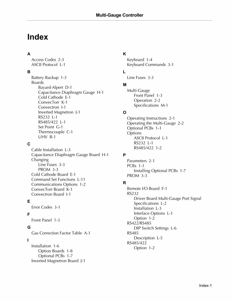
Multi-Gauge Controller
DR
AF
T 2
/6/0
4
Index
�
Access Codes 2-3ASCII Protocol L-1
�
Battery Backup 1-3Boards
Bayard-Alpert D-1Capacitance Diaphragm Gauge H-1Cold Cathode E-1ConvecTorr K-1Convectron I-1Inverted Magnetron J-1RS232 L-1RS485/422 L-1Set Point G-1Thermocouple C-1UHV B-1
�
Cable Installation L-3Capacitance Diaphragm Gauge Board H-1Changing
Line Fuses 3-3PROM 3-3
Cold Cathode Board E-1Command Set Functions L-11Communications Options 1-2ConvecTorr Board K-1Convectron Board I-1
�
Error Codes 3-1
�
Front Panel 1-3
�
Gas Correction Factor Table A-1
�
Installation 1-6Option Boards 1-8Optional PCBs 1-7
Inverted Magnetron Board J-1
�
Keyboard 1-4Keyboard Commands 3-1
Line Fuses 3-3
Multi-GaugeFront Panel 1-3Operation 2-2Specifications M-1
�
Operating Instructions 2-1Operating the Multi-Gauge 2-2Optional PCBs 1-1Options
ASCII Protocol L-1RS232 L-1RS485/422 1-2
�
Parameters 2-1PCBs 1-1
Installing Optional PCBs 1-7PROM 3-3
Remote I/O Board F-1RS232
Driver Board Multi-Gauge Port Signal Specifications L-2Installation L-3Interface Options L-1Option 1-2
RS422/RS485DIP Switch Settings L-6
RS485Description L-5
RS485/422Option 1-2
Index-1
Multi-Gauge Controller D
RA
FT
2/6
/04
�
Section 1-1Set Point Board G-1Setting Line Voltage 1-7Setting Parameters 2-1
�
Thermocouple Board C-1Troubleshooting 3-1
�
UHV Board B-1Unpacking 1-6
Index-2


Sales and Service Offices
07/03
ArgentinaVarian Argentina Ltd.Sucursal ArgentinaAv. Ricardo Balbin 23161428 Buenos AiresArgentinaTel: (54) 1 783 5306Fax: (54) 1 786 5172
BeneluxVarian Vacuum TechnologiesRijksstraatweg 269 H,3956 CP LeersumThe NetherlandsTel: (31) 343 469910Fax: (31) 343 469961
BrazilVarian Industria e Comercio Ltda.Avenida Dr. Cardoso de Mello 1644Vila OlimpiaSao Paulo 04548 005BrazilTel: (55) 11 3845 0444Fax: (55) 11 3845 9350
CanadaCentral coordination through:Varian Vacuum Technologies121 Hartwell AvenueLexington, MA 02421USATel: (781) 861 7200Fax: (781) 860 5437Toll Free: (800) 882 7426
ChinaVarian Technologies - BeijingRoom 1201, Jinyu MansionNo. 129A, Xuanwumen XidajieXicheng DistrictBeijing 1000031 P.R. ChinaTel: (86) 10 6641 1530Fax: (86) 10 6641 1534
France and WallonieVarian s.a.7 avenue des TropiquesZ.A. de Courtaboeuf � B.P. 12Les Ulis cedex (Orsay) 91941FranceTel: (33) 1 69 86 38 13Fax: (33) 1 69 28 23 08
Germany and AustriaVarian Deutschland GmbHAlsfelder Strasse 6Postfach 11 14 3564289 DarmstadtGermanyTel: (49) 6151 703 353Fax: (49) 6151 703 302
IndiaVarian India PVT LTD101-108, 1st Floor1010 Competent House7, Nangal Raya Business CentreNew Delhi 110 046IndiaTel: (91) 11 5548444Fax: (91) 11 5548445
ItalyVarian Vacuum TechnologiesVia F.lli Varian, 5410040 Leini, (Torino)ItalyTel (39) 011 997 9 111Fax (39) 011 997 9 350
JapanVarian Vacuum TechnologiesSumitomo Shibaura Building, 8th Floor4-16-36 ShibauraMinato-ku, Tokyo 108JapanTel: (81) 3 5232 1253Fax: (81) 3 5232 1263
KoreaVarian Technologies Korea, Ltd.Shinsa 2nd Building 2F966-5 Daechi-dong Kangnam-gu, SeoulKorea 135-280Tel: (82) 2 3452 2452Fax: (82) 2 3452 2451
MexicoVarian S.A.Concepcion Beistegui No 109Col Del ValleC.P. 03100Mexico, D.F.Tel: (52) 5 523 9465Fax: (52) 5 523 9472
TaiwanVarian Technologies Asia Ltd. 14F-16 No.77, Hsin Tai Wu Road Sec. 1, Hsi Chih, Taipei HsienTaiwan, R.O.C.Tel: (886) 2 2698 9555Fax: (886) 2 2698 9678
UK and Ireland Varian Ltd.28 Manor RoadWalton-On-ThamesSurrey KT 12 2QFEnglandTel: (44) 1932 89 8000Fax: (44) 1932 22 8769
United StatesVarian Vacuum Technologies121 Hartwell AvenueLexington, MA 02421USATel: (781) 861 7200Fax: (781) 860 5437
Other CountriesVarian Vacuum Technologies
Via F.lli Varian, 5410040 Leini, (Torino)ItalyTel: (39) 011 997 9 111Fax: (39) 011 997 9 350
Customer Support and Service:
North AmericaTel: 1 (800) 882-7426 (toll-free)[email protected]
EuropeTel: 00 (800) 234 234 00 (toll-free)[email protected]
JapanTel: (81) 3 5232 1253 (dedicated line)[email protected]
KoreaTel (82) 2 3452 2452 (dedicated line)[email protected]
TaiwanTel: 0 (800) 051 342 (toll-free)[email protected]
Worldwide Web Site, Catalog and On-line Orders:www.varianinc.com
Representatives in most countries
Sales and Service Offices