vantage 500 cummins - lincoln electric
TRANSCRIPT
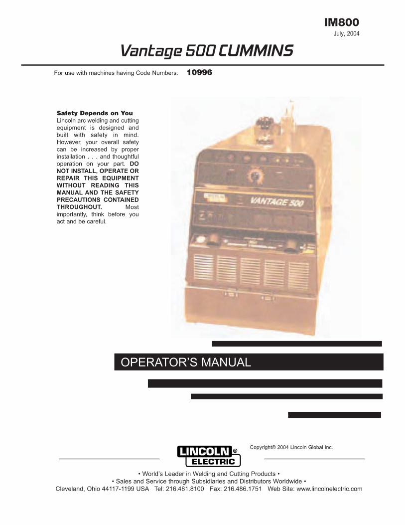
July, 2004
Safety Depends on YouLincoln arc welding and cuttingequipment is designed andbuilt with safety in mind.However, your overall safetycan be increased by properinstallation . . . and thoughtfuloperation on your part. DONOT INSTALL, OPERATE ORREPAIR THIS EQUIPMENTWITHOUT READING THISMANUAL AND THE SAFETYPRECAUTIONS CONTAINEDTHROUGHOUT. Mostimportantly, think before youact and be careful.
OPERATOR’S MANUAL
Copyright© 2004 Lincoln Global Inc.
• World’s Leader in Welding and Cutting Products •• Sales and Service through Subsidiaries and Distributors Worldwide •
Cleveland, Ohio 44117-1199 USA Tel: 216.481.8100 Fax: 216.486.1751 Web Site: www.lincolnelectric.com
IM800
For use with machines having Code Numbers: 10996
Vantage 500 CUMMINS

ELECTRIC ANDMAGNETIC FIELDSmay be dangerous
2.a.Electric current flowing through any conductor causeslocalized Electric and Magnetic Fields (EMF). Weldingcurrent creates EMF fields around welding cables andwelding machines.
2.b.EMF fields may interfere with some pacemakers and weldershaving a pacemaker should consult their physician beforewelding.
2.c. Exposure to EMF fields in welding may have other healtheffects which are now not known.
2.d.All welders should use the following procedures in order tominimize exposure to EMF fields from the welding circuit:
2.d.1. Route the electrode and work cables together.Secure them with tape when possible.
2.d.2. Never coil the electrode lead around your body.
2.d.3. Do not place your body between the electrodeand work cables. If the electrode cable is on yourright side, the work cable should also be on yourright side.
2.d.4. Connect the work cable to the workplace asclose as possible to the area being welded.
2.d.5. Do not work next to welding power source.
1.h. To avoid scalding, do not remove theradiator pressure cap when the engine ishot.
For Diesel Engines: diesel engine exhaust andsome of its constituents are known to the State ofCalifornia to cause cancer, birth defects, and otherreproductive harm.
For Gasoline Engines: The engine exhaust from thisproduct contains chemicals known to the State ofCalifornia to cause cancer, birth defects, or otherreproductive harm.
ARC WELDING CAN BE HAZARDOUS. PROTECT YOURSELF AND OTHERS FROM POSSIBLE SERIOUS INJURY OR DEATH.KEEP CHILDREN AWAY. PACEMAKER WEARERS SHOULD CONSULT WITH THEIR DOCTOR BEFORE OPERATING.
Read and understand the following safety highlights. For additional safety information, it is strongly recommended that youpurchase a copy of “Safety in Welding & Cutting - ANSI Standard Z49.1” from the American Welding Society, PO Box351040, Miami, Florida 33135 or CSA Standard W117.2-1974 or WTIA (Welding Technology Institute of Australia), PO Box6165, Silverwater, NSW, 2128. A free copy of “Arc Welding Safety” booklet E205 is available from the Lincoln ElectricalCompany, 22801 St Clair Avenue, Cleveland, Ohio 44117-1199.
BE SURE THAT ALL INSTALLATION, OPERATION, MAINTENANCE AND REPAIR PROCEDURES AREPERFORMED ONLY BY QUALIFIED INDIVIDUALS.
1.a Turn the engine off before troubleshooting and maintenancework unless the maintenance work requires it to be running.
1.b. Operate engines in open, well ventilatedareas or vent the engine exhaust fumesoutdoors.
1.c. Do not add fuel near an open flame, weldingarc or when the engine is running. Stop theengine and allow it to cool before refuellingto prevent spilled fuel from vaporizing oncontact with hot engine parts and igniting.Do not spill fuel when filling tank. If fuel isspilled, wipe it up and do not start engineuntil fumes have been eliminated.
1.d.Keep all equipment, safety guards, covers and devices inposition and in good repair. Keep hands, hair, clothing andtools away from V-belts, gears, fans and all other movingparts when starting, operating or repairing equipment.
1.e. In some cases it may be necessary to remove safety guardsto perform required maintenance. Remove guards only whennecessary and replace them when the maintenancerequiring their removal is complete. Always use the greatestcare when working near moving parts.
1.f. Do not put your hands near the engine fan.Do not attempt to override the governor oridler by pushing on the throttle control rodswhile the engine is running.
1.g.To prevent accidentally starting petrol engines while turningthe engine or welding generator during maintenance work,disconnect the spark plug wires, distributor cap or magnetowire as appropriate.
i SAFETY i
CALIFORNIA PROPOSITION 65 WARNINGS
WARNING
FOR ENGINEpowered equipment.
Mar ‘95

ELECTRIC SHOCKcan kill.3.a. The electrode and work (or ground) circuits
are electrically “hot” when the welder is on.Do not touch these “hot” parts with your bareskin or wet clothing. Wear dry, hole-freegloves to insulate hands.
3.b. Insulate yourself from work and ground using dryinsulation. Make certain the insulation is large enough tocover your full area of physical contact with work andground.
In addition to the normal safety precautions, if weldingmust be performed under electrically hazardousconditions (in damp locations or while wearing wetclothing; on metal structures such as floors, gratingsor scaffolds; when in cramped positions such assitting, kneeling or lying, if there is a high risk ofunavoidable or accidental contact with the workpieceor ground) use the following equipment:
• Semiautomatic DC Constant Voltage (Wire) Welder.
• DC Manual (Stick) Welder.
• AC Welder with Reduced Voltage Control.
3.c. In semi-automatic or automatic wire welding, theelectrode, electrode reel, welding head, nozzle or semi-automatic welding gun are also electrically “hot”.
3.d. Always be sure the work cable makes a good electricalconnection with the metal being welded. The connectionshould be as close as possible to the area being welded.
3.e. Ground the work or metal to be welded to a good electrical(earth) ground.
3.f. Maintain the electrode holder, work clamp, welding cableand welding machine in good, safe operating condition.Replace damaged insulation.
3.g. Never dip the electrode holder in water for cooling.
3.h. Never simultaneously touch electrically “hot” parts ofelectrode holders connected to two welders becausevoltage between the two can be the total of the open circuitvoltage of both welders.
3.i. When working above floor level, use a safety belt toprotect yourself from a fall should you get a shock.
3.j. Also see items 6c and 8.
FUMES AND GASEScan be dangerous5.a. Welding may produce fumes and gases
hazardous to health. Avoid breathing thesefumes and gases. When welding, keep yourhead out of the fume. Use enoughventilation and/or exhaust at the arc to
keep fumes and gases away from the breathing zone. Whenwelding with electrodes which require special ventilationsuch as stainless or hard facing (see instructions oncontainer or MSDS) or on lead or cadmium plated steel andother metals or coatings which produce highly toxic fumes,keep exposure as low as possible and below ThresholdLimit values (TLV) using local exhaust or mechanicalventilation. In confined spaces or in some circumstances,outdoors, a respirator may be required. Additionalprecautions are also required when welding on galvanizedsteel.
5.b.Do not weld in locations near chlorinated hydrocarbonvapors coming from degreasing, cleaning or sprayingoperations. The heat and rays of the arc can react withsolvent vapors to form phosgene, a highly toxic gas, andother irritating products.
5.c. Shielding gases used for arc welding can displace air andcause injury or death. Always use enough ventilation,especially in confined areas, to ensure breathing air is safe.
5.d.Read and understand the manufacturer’s instructions for thisequipment and the consumables to be used, including thematerial safety data sheet (MSDS) and follow youremployer’s safety practices. MSDS forms are available fromyour welding distributor or from the manufacturer.
5.e.Also see Item 1b.
ARC RAYS can burn.4 a Use a shield with the proper filter and cover
plates to protect your eyes from sparks andthe rays of the arc when welding orobserving open arc welding. Headshieldand filter lens should conform to ANSIZ87.1 standards.
4.b.Use suitable clothing made from durable flame resistantmaterial to protect your skin and that of your helpers from thearc rays.
4.c. Protect other nearby personnel with suitable non flammablescreening and/or warn them not to watch the arc or exposethemselves to the arc rays or to hot spatter or metal.
Mar ‘95
ii SAFETY ii

FOR ELECTRICALLYpowered equipment.8.a. Turn off input power using the disconnect
switch at the fuse box before working on theequipment.
8.b. Install equipment in accordance with the National ElectricalCode, all local codes and the manufacturer’srecommendations.
8.c. Ground the equipment in accordance with the NationalElectrical Code and the manufacturer’s recommendations.
WELDING SPARKS cancause fire or explosion6 a Remove fire hazards from the welding area. If
this is not possible, cover them to prevent thewelding sparks from starting a fire. Rememberthat welding sparks and hot materials from
welding can easily go through small cracks and openings toadjacent areas. Avoid welding near hydraulic lines. Have a fireextinguisher readily available.6.b.Where compressed gases are to be used at the job site,
special precautions should be used to prevent hazardoussituations. Refer to AS1674 Parts 1 & 2 “Safety in Weldingand Cutting” (ANSI Standard Z49.1) and the operatinginformation for the equipment being used.
6.c. When not welding, make certain no part of the electrodecircuit is touching the work or ground. Accidental contact cancause overheating and create a fire hazard.
6.d.Do not heat, cut or weld tanks, drums or containers until theproper steps have been taken to insure that such procedureswill not cause flammable or toxic vapors from substancesinside. These can cause an explosion even though thevessel has been “cleaned”. For information purchase“Recommended Safe Practices for the Preparation forWelding and Cutting of Containers and Piping that have heldHazardous Substances”, AWS F4.1 from the AmericanWelding Society (see address above).
6.e.Vent hollow castings or containers before heating, cutting orwelding. They may explode.
6.f. Sparks and spatter are thrown from the welding arc. Wear oilfree protective garments such as leather gloves, heavy shirt,cuffless trousers, high shoes and a cap over your hair. Wearear plugs when welding out of position or in confined places.Always wear safety glasses with side shields when in awelding area.
6.g.Connect the work cable to the work as close to the weldingarea as possible. Work cables connected to the buildingframework or other locations away from the welding areaincrease the possibility of the welding current passingthrough lifting chains, crane cables or other alternate circuits.This can create fire hazards or overheat lifting chains orcables until they fail.
6.h.Also see Item 1c.
CYLINDER may explodeif damaged7.a. Use only compressed gas cylinders containing
the correct shielding gas for the process usedand properly operating regulators, designedfor the gas and pressure used. All hoses,
fittings, etc. should be suitable for the application andmaintained in good condition.
7.b.Always keep cylinders in an upright position and securelychained to an undercarriage or fixed support.
7.c. Cylinders should be located :
• Away from areas where they may be struck or subjected tophysical damage.
• A safe distance from arc welding or cutting operations andany other source of heat, sparks or flame.
7.d.Never allow the electrode, electrode holder, or any otherelectrically “hot” parts to touch a cylinder.
7.e.Keep your head and face away from the cylinder valve outletwhen opening the cylinder valve.
7.f. Valve protection caps should always be in place and hand-tight except when the cylinder is in use or connected for use.
7.g.Read and follow the instructions on compressed gascylinders, associated equipment, and CGA publication P-I,“Precautions for Safe Handling of Compressed Gases inCylinders”, available from the Compressed Gas Association1235 Jefferson Davis Highway, Arlington, VA 22202.
iii SAFETY iii
Mar ‘95

iv SAFETY iv
Mar. ‘93
PRÉCAUTIONS DE SÛRETÉPour votre propre protection lire et observer toutes les instructionset les précautions de sûreté specifiques qui parraissent dans cemanuel aussi bien que les précautions de sûreté généralessuivantes:
Sûreté Pour Soudage A L’Arc1. Protegez-vous contre la secousse électrique:
a. Les circuits à l’électrode et à la piéce sont sous tensionquand la machine à souder est en marche. Eviter toujourstout contact entre les parties sous tension et la peau nueou les vétements mouillés. Porter des gants secs et sanstrous pour isoler les mains.
b. Faire trés attention de bien s’isoler de la masse quand onsoude dans des endroits humides, ou sur un planchermetallique ou des grilles metalliques, principalement dans les positions assis ou couché pour lesquelles une grandepartie du corps peut être en contact avec la masse.
c. Maintenir le porte-électrode, la pince de masse, le câble desoudage et la machine à souder en bon et sûr étatdefonctionnement.
d.Ne jamais plonger le porte-électrode dans l’eau pour lerefroidir.
e. Ne jamais toucher simultanément les parties sous tensiondes porte-électrodes connectés à deux machines à souderparce que la tension entre les deux pinces peut être le totalde la tension à vide des deux machines.
f. Si on utilise la machine à souder comme une source decourant pour soudage semi-automatique, ces precautionspour le porte-électrode s’applicuent aussi au pistolet desoudage.
2. Dans le cas de travail au dessus du niveau du sol, se protégercontre les chutes dans le cas ou on recoit un choc. Ne jamaisenrouler le câble-électrode autour de n’importe quelle partie ducorps.
3. Un coup d’arc peut être plus sévère qu’un coup de soliel, donc:
a. Utiliser un bon masque avec un verre filtrant approprié ainsiqu’un verre blanc afin de se protéger les yeux durayonnement de l’arc et des projections quand on soude ouquand on regarde l’arc.
b. Porter des vêtements convenables afin de protéger la peaude soudeur et des aides contre le rayonnement de l‘arc.
c. Protéger l’autre personnel travaillant à proximité ausoudage à l’aide d’écrans appropriés et non-inflammables.
4. Des gouttes de laitier en fusion sont émises de l’arc desoudage. Se protéger avec des vêtements de protection libresde l’huile, tels que les gants en cuir, chemise épaisse,pantalons sans revers, et chaussures montantes.
5. Toujours porter des lunettes de sécurité dans la zone desoudage. Utiliser des lunettes avec écrans lateraux dans leszones où l’on pique le laitier.
6. Eloigner les matériaux inflammables ou les recouvrir afin deprévenir tout risque d’incendie dû aux étincelles.
7. Quand on ne soude pas, poser la pince à une endroit isolé dela masse. Un court-circuit accidental peut provoquer unéchauffement et un risque d’incendie.
8. S’assurer que la masse est connectée le plus prés possible dela zone de travail qu’il est pratique de le faire. Si on place lamasse sur la charpente de la construction ou d’autres endroitséloignés de la zone de travail, on augmente le risque de voirpasser le courant de soudage par les chaines de levage,câbles de grue, ou autres circuits. Cela peut provoquer desrisques d’incendie ou d’echauffement des chaines et descâbles jusqu’à ce qu’ils se rompent.
9. Assurer une ventilation suffisante dans la zone de soudage.Ceci est particuliérement important pour le soudage de tôlesgalvanisées plombées, ou cadmiées ou tout autre métal quiproduit des fumeés toxiques.
10. Ne pas souder en présence de vapeurs de chlore provenantd’opérations de dégraissage, nettoyage ou pistolage. Lachaleur ou les rayons de l’arc peuvent réagir avec les vapeursdu solvant pour produire du phosgéne (gas fortement toxique)ou autres produits irritants.
11. Pour obtenir de plus amples renseignements sur la sûreté, voirle code “Code for safety in welding and cutting” CSA StandardW 117.2-1974.
PRÉCAUTIONS DE SÛRETÉ POURLES MACHINES À SOUDER ÀTRANSFORMATEUR ET ÀREDRESSEUR
1. Relier à la terre le chassis du poste conformement au code del’électricité et aux recommendations du fabricant. Le dispositifde montage ou la piece à souder doit être branché à unebonne mise à la terre.
2. Autant que possible, I’installation et l’entretien du poste seronteffectués par un électricien qualifié.
3. Avant de faires des travaux à l’interieur de poste, ladebrancher à l’interrupteur à la boite de fusibles.
4. Garder tous les couvercles et dispositifs de sûreté à leur place.

v v
Thank You for selecting a QUALITY product by Lincoln Electric. We want youto take pride in operating this Lincoln Electric Company product •••as much pride as we have in bringing this product to you!
Read this Operators Manual completely before attempting to use this equipment. Save this manual and keep ithandy for quick reference. Pay particular attention to the safety instructions we have provided for your protection.The level of seriousness to be applied to each is explained below:
WARNINGThis statement appears where the information must be followed exactly to avoid serious personal injury orloss of life.
This statement appears where the information must be followed to avoid minor personal injury or damage tothis equipment.
CAUTION
Please Examine Carton and Equipment For Damage ImmediatelyWhen this equipment is shipped, title passes to the purchaser upon receipt by the carrier. Consequently, Claimsfor material damaged in shipment must be made by the purchaser against the transportation company at the timethe shipment is received.
Please record your equipment identification information below for future reference. This information can be foundon your machine nameplate.
Product _________________________________________________________________________________
Model Number ___________________________________________________________________________
Code Number or Date Code_________________________________________________________________
Serial Number____________________________________________________________________________
Date Purchased___________________________________________________________________________
Where Purchased_________________________________________________________________________
Whenever you request replacement parts or information on this equipment, always supply the information youhave recorded above. The code number is especially important when identifying the correct replacement parts.
On-Line Product Registration
- Register your machine with Lincoln Electric either via fax or over the Internet.
• For faxing: Complete the form on the back of the warranty statement included in the literature packetaccompanying this machine and fax the form per the instructions printed on it.
• For On-Line Registration: Go to our WEB SITE at www.lincolnelectric.com. Choose “Quick Links” and then“Product Registration”. Please complete the form and submit your registration.

PageInstallation . . . . . . . . . . . . . . . . . . . . . . . . . . . . . . . . . . . . . . . . . . . . . . . . . . . . . . . . . . . . . . . . . . . .Section A
Technical Specifications . . . . . . . . . . . . . . . . . . . . . . . . . . . . . . . . . . . . . . . . . . . . . . . . . . . . . . . . . . .A-1Safety Precautions . . . . . . . . . . . . . . . . . . . . . . . . . . . . . . . . . . . . . . . . . . . . . . . . . . . . . . . . . . . . . . .A-2Location / Ventilation . . . . . . . . . . . . . . . . . . . . . . . . . . . . . . . . . . . . . . . . . . . . . . . . . . . . . . . . . . . . . .A-2
Storing . . . . . . . . . . . . . . . . . . . . . . . . . . . . . . . . . . . . . . . . . . . . . . . . . . . . . . . . . . . . . . . . .A-2Stacking . . . . . . . . . . . . . . . . . . . . . . . . . . . . . . . . . . . . . . . . . . . . . . . . . . . . . . . . . . . . . . . .A-2Angle of Operation . . . . . . . . . . . . . . . . . . . . . . . . . . . . . . . . . . . . . . . . . . . . . . . . . . . . . . . .A-2Lifting . . . . . . . . . . . . . . . . . . . . . . . . . . . . . . . . . . . . . . . . . . . . . . . . . . . . . . . . . . . . . . . . . .A-3High Altitude Operation . . . . . . . . . . . . . . . . . . . . . . . . . . . . . . . . . . . . . . . . . . . . . . . . . . . .A-3High Temperature Operation . . . . . . . . . . . . . . . . . . . . . . . . . . . . . . . . . . . . . . . . . . . . . . . .A-3Towing . . . . . . . . . . . . . . . . . . . . . . . . . . . . . . . . . . . . . . . . . . . . . . . . . . . . . . . . . . . . . . . . .A-3
Pre-Operation Engine Service . . . . . . . . . . . . . . . . . . . . . . . . . . . . . . . . . . . . . . . . . . . . . . . . . . . . . .A-4Oil . . . . . . . . . . . . . . . . . . . . . . . . . . . . . . . . . . . . . . . . . . . . . . . . . . . . . . . . . . . . . . . . . . . . .A-4Fuel . . . . . . . . . . . . . . . . . . . . . . . . . . . . . . . . . . . . . . . . . . . . . . . . . . . . . . . . . . . . . . . . . . . .A-4Fuel Cap . . . . . . . . . . . . . . . . . . . . . . . . . . . . . . . . . . . . . . . . . . . . . . . . . . . . . . . . . . . . . . . .A-4Engine Cooling System . . . . . . . . . . . . . . . . . . . . . . . . . . . . . . . . . . . . . . . . . . . . . . . . . . . .A-4Battery Connection . . . . . . . . . . . . . . . . . . . . . . . . . . . . . . . . . . . . . . . . . . . . . . . . . . . . . . . .A-4Muffler Outlet Pipe . . . . . . . . . . . . . . . . . . . . . . . . . . . . . . . . . . . . . . . . . . . . . . . . . . . . . . . .A-5Spark Arrestor . . . . . . . . . . . . . . . . . . . . . . . . . . . . . . . . . . . . . . . . . . . . . . . . . . . . . . . . . . .A-5
Radiator Cap Cover . . . . . . . . . . . . . . . . . . . . . . . . . . . . . . . . . . . . . . . . . . . . . . . . . . . . . . . . . . . . . .A-5Air Cleaner Inlet Hood . . . . . . . . . . . . . . . . . . . . . . . . . . . . . . . . . . . . . . . . . . . . . . . . . . . . . . . . . . . . .A-5Welding Terminals . . . . . . . . . . . . . . . . . . . . . . . . . . . . . . . . . . . . . . . . . . . . . . . . . . . . . . . . . . . . . . . .A-5
Welding Output Cables . . . . . . . . . . . . . . . . . . . . . . . . . . . . . . . . . . . . . . . . . . . . . . . . . . . .A-5Machine Grounding . . . . . . . . . . . . . . . . . . . . . . . . . . . . . . . . . . . . . . . . . . . . . . . . . . . . . . . . . . . . . . .A-5Remote Control . . . . . . . . . . . . . . . . . . . . . . . . . . . . . . . . . . . . . . . . . . . . . . . . . . . . . . . . . . . . . . . . . .A-6Auxiliary Power Receptacles . . . . . . . . . . . . . . . . . . . . . . . . . . . . . . . . . . . . . . . . . . . . . . . . . . . . . . . .A-6Standby Power Connections . . . . . . . . . . . . . . . . . . . . . . . . . . . . . . . . . . . . . . . . . . . . . . . . . . . . . . . .A-6Connection of Vantage Premises Wiring . . . . . . . . . . . . . . . . . . . . . . . . . . . . . . . . . . . . . . . . . . . . . . .A-7Connection of Lincoln Electric Wire Feeders . . . . . . . . . . . . . . . . . . . . . . . . . . . . . . . . . . . . . . . . .A-8, A-9
Operation . . . . . . . . . . . . . . . . . . . . . . . . . . . . . . . . . . . . . . . . . . . . . . . . . . . . . . . . . . . . . . . . . . . .Section BSafety Instructions . . . . . . . . . . . . . . . . . . . . . . . . . . . . . . . . . . . . . . . . . . . . . . . . . . . . . . . . . . . . . . . .B-1General Description . . . . . . . . . . . . . . . . . . . . . . . . . . . . . . . . . . . . . . . . . . . . . . . . . . . . . . . . . . . . . . .B-1
Recommended Applications . . . . . . . . . . . . . . . . . . . . . . . . . . . . . . . . . . . . . . . . . . . . . . . . .B-1Controls and Settings . . . . . . . . . . . . . . . . . . . . . . . . . . . . . . . . . . . . . . . . . . . . . . . . . . . . . . . . . . . . .B-2
Engine Controls . . . . . . . . . . . . . . . . . . . . . . . . . . . . . . . . . . . . . . . . . . . . . . . . . . . . . . . .B-2, B-3Welder Controls . . . . . . . . . . . . . . . . . . . . . . . . . . . . . . . . . . . . . . . . . . . . . . . . . . . . . . . . . .B-4Auxiliary Power Controls . . . . . . . . . . . . . . . . . . . . . . . . . . . . . . . . . . . . . . . . . . . . . . . . . . .B-4
Engine Operation . . . . . . . . . . . . . . . . . . . . . . . . . . . . . . . . . . . . . . . . . . . . . . . . . . . . . . . . . . . . . . . .B-5Starting the Engine . . . . . . . . . . . . . . . . . . . . . . . . . . . . . . . . . . . . . . . . . . . . . . . . . . . . . . . .B-5Stopping the Engine . . . . . . . . . . . . . . . . . . . . . . . . . . . . . . . . . . . . . . . . . . . . . . . . . . . . . . .B-5
Break-In Period . . . . . . . . . . . . . . . . . . . . . . . . . . . . . . . . . . . . . . . . . . . . . . . . . . . . . . . . . . . . . . . . . .B-6Typical Fuel Consumption . . . . . . . . . . . . . . . . . . . . . . . . . . . . . . . . . . . . . . . . . . . . . . . . . .B-6Duty Cycle . . . . . . . . . . . . . . . . . . . . . . . . . . . . . . . . . . . . . . . . . . . . . . . . . . . . . . . . . . . . . .B-6
Welding Operation . . . . . . . . . . . . . . . . . . . . . . . . . . . . . . . . . . . . . . . . . . . . . . . . . . . . . . . . . . . . . . . .B-6Stick Welding Mode . . . . . . . . . . . . . . . . . . . . . . . . . . . . . . . . . . . . . . . . . . . . . . . . . . . . . . .B-6CC-Stick Mode . . . . . . . . . . . . . . . . . . . . . . . . . . . . . . . . . . . . . . . . . . . . . . . . . . . . . . . . . . .B-6Downhill Pipe Mode . . . . . . . . . . . . . . . . . . . . . . . . . . . . . . . . . . . . . . . . . . . . . . . . . . . . . . .B-6Touch Start TIG Mode . . . . . . . . . . . . . . . . . . . . . . . . . . . . . . . . . . . . . . . . . . . . . . . . . . . . .B-6Vantage Settings when using K930-2 TIG Module . . . . . . . . . . . . . . . . . . . . . . . . . . . . . . .B-7
Typical Current Ranges for Tungsten Electrodes . . . . . . . . . . . . . . . . . . . . . . . . . . . . . . . . . . . . . . . .B-7CV-Wire Mode . . . . . . . . . . . . . . . . . . . . . . . . . . . . . . . . . . . . . . . . . . . . . . . . . . . . . . . . . . .B-8Arc Gouging . . . . . . . . . . . . . . . . . . . . . . . . . . . . . . . . . . . . . . . . . . . . . . . . . . . . . . . . . . . . .B-8Paralleling . . . . . . . . . . . . . . . . . . . . . . . . . . . . . . . . . . . . . . . . . . . . . . . . . . . . . . . . . . . . . . .B-8
Auxiliary Power Operation . . . . . . . . . . . . . . . . . . . . . . . . . . . . . . . . . . . . . . . . . . . . . . . . . . . . . . . . . .B-8Simultaneous Welding and Auxiliary Power Loads . . . . . . . . . . . . . . . . . . . . . . . . . . . . . . .B-8
Simultaneous Welding and Power Loads, Extension Cord Length Recommendations . . . . . . . . . . .B-9
vi vi
Vantage 500 CUMMINS
TABLE OF CONTENTS

Accessories . . . . . . . . . . . . . . . . . . . . . . . . . . . . . . . . . . . . . . . . . . . . . . . . . . . . . . . . . . . . . . . . . . . .Section COptional Field Installed Accessories . . . . . . . . . . . . . . . . . . . . . . . . . . . . . . . . . . . . . . . . . . . . . . . . . .C-1
_________________________________________________________________________________________________
Maintenance . . . . . . . . . . . . . . . . . . . . . . . . . . . . . . . . . . . . . . . . . . . . . . . . . . . . . . . . . . . . . . . . . . . .Section DSafety Precautions . . . . . . . . . . . . . . . . . . . . . . . . . . . . . . . . . . . . . . . . . . . . . . . . . . . . . . . . . . . . . . .D-1Routine and Periodic Maintenance . . . . . . . . . . . . . . . . . . . . . . . . . . . . . . . . . . . . . . . . . . . . . . . . . . .D-1Engine Maintenance . . . . . . . . . . . . . . . . . . . . . . . . . . . . . . . . . . . . . . . . . . . . . . . . . . . . . . . . . . . . . .D-1
Air Filter . . . . . . . . . . . . . . . . . . . . . . . . . . . . . . . . . . . . . . . . . . . . . . . . . . . . . . . . . . . . . . . .D-1Fuel Filters . . . . . . . . . . . . . . . . . . . . . . . . . . . . . . . . . . . . . . . . . . . . . . . . . . . . . . . . . . . . . .D-2Cooling System . . . . . . . . . . . . . . . . . . . . . . . . . . . . . . . . . . . . . . . . . . . . . . . . . . . . . . . . . .D-2Battery Handling . . . . . . . . . . . . . . . . . . . . . . . . . . . . . . . . . . . . . . . . . . . . . . . . . . . . . . . . . .D-2
Charging the Battery . . . . . . . . . . . . . . . . . . . . . . . . . . . . . . . . . . . . . . . . . . . . . . . . . . . . . . . . . . . . . .D-2Nameplate / Warning Decal Maintenance . . . . . . . . . . . . . . . . . . . . . . . . . . . . . . . . . . . . . . . . . . . . . .D-3Welder / Generator Maintenance . . . . . . . . . . . . . . . . . . . . . . . . . . . . . . . . . . . . . . . . . . . . . . . . . . . .D-3Engine Maintenance Components . . . . . . . . . . . . . . . . . . . . . . . . . . . . . . . . . . . . . . . . . . . . . . . . . . .D-3
Troubleshooting . . . . . . . . . . . . . . . . . . . . . . . . . . . . . . . . . . . . . . . . . . . . . . . . . . . . . . . . . . . . . . . . . . . .Section E
Wiring, Connection Diagrams and Dimension Print . . . . . . . . . . . . . . . . . . . . . . . . . . . . . . . . . . . . . . . .Section F
Parts Lists . . . . . . . . . . . . . . . . . . . . . . . . . . . . . . . . . . . . . . . . . . . . . . . . . . . . . . . . . . . . . . . . . . .P-472 Series
vii vii
Vantage 500 CUMMINS
TABLE OF CONTENTS

TECHNICAL SPECIFICATIONS - Vantage 500 CUMMINS (K2272-1)
INPUT - DIESEL ENGINE
Make /Model Description Speed (RPM) Displacement Starting CapacitiesSystem
Cummins 4 cylinder High Idle 1900 199 cu. in 12VDC battery Fuel B3.3 56HP (42 kw) Low Idle 1425 (3.3L) & Starter (25 US gal)Diesel Engine @ 1800 RPM Full Load 1800 94.6L
Bore x Stroke Oil: (2 US gal)
3.74” x 4.53” 7.5L(95mm x 115mm) Coolant:
(2.6 US gal)11.8L
RATED OUTPUT @ 104°F(40°C) - WELDERDuty Cycle Welding Output Volts at Rated Amps
100% 500 Amps (DC multi-purpose) 40 Volts
60% 550 Amps (DC multi-purpose) 36 volts
50% 575 Amps (DC multi-purpose) 35 volts
PHYSICAL DIMENSIONSHeight (2) Width Depth Weight
42.0 in 31.5 in. 63.1 in. 1605 lbs.(1066.8 mm) (800.1mm) (1603mm) (728kg)
(Approx)1. Output rating in watts is equivalent to volt-amperes at unity power factor.
Output voltage is within +/- 10% at all loads up to rated capacity. When welding, available auxiliary power will be reduced.2. Top of Enclosure. Add 8.8” (223.5mm) for exhaust.
OUTPUT @ 104°F(40°C) - WELDER AND GENERATOR
Welding Range30 - 575 Amps CC/CV
20 - 250 Amps TIG
Open Circuit Voltage60 Max OCV @ 1900 RPM
Auxiliary Power (1)
120/240 VAC12,000 WATTS, 60 Hz.
A-1 INSTALLATION A-1
Vantage 500 CUMMINS
Read this entire installation section before you startinstallation.
SAFETY PRECAUTIONS
Do not attempt to use this equipment until you havethoroughly read all operating and maintenance manualssupplied with your machine. They include important safetyprecautions, detailed engine starting, operating andmaintenance instructions and parts lists.
ELECTRIC SHOCK can kill.• Do not touch electrically live parts such as
output terminals or internal wiring.• Insulate yourself from the work and ground.• Always wear dry insulating gloves.
-------------------------------------------------------------------------------------
ENGINE EXHAUST can kill.• Use in open, well ventilated areas or vent
exhaust outside
-------------------------------------------------------------------------------------
MOVING PARTS can injure.• Do not operate with doors open or guards off.• Stop engine before servicing.• Keep away from moving parts
-------------------------------------------------------------------------------------
Only qualified personnel should install, use or service thisequipment.
LOCATION / VENTILATIONThe welder should be located to provide an unrestricted flow ofclean, cool air to the cooling air inlets and to avoid restricting thecooling air outlets. Also, locate the welder so that the engineexhaust fumes are properly vented to an outside area.
DO NOT MOUNT OVER COMBUSTIBLE SURFACESWhere there is a combustible surface directly under stationary orfixed electrical equipment, that surface should be covered with asteel plate at least .06”(1.6mm) thick, which should extend notless than 5.90”(150mm) beyond the equipment on all sides.
--------------------------------------------------------------------------------------
STORING1. Store the machine in a cool, dry place when it is not in use.
Protect it from dust and dirt. Keep it where it can’t beaccidentally damaged from construction activities, movingvehicles, and other hazards.
2. Drain the engine oil and refill with fresh 10W30 oil. Run theengine for about five minutes to circulate oil to all the parts.See the MAINTENANCE section of this manual for detailson changing oil.
3. Remove the battery, recharge it, and adjust the electrolytelevel. Store the battery in a dry, dark place.
STACKINGVantage machines cannot be stacked.
ANGLE OF OPERATIONTo achieve optimum engine performance the Vantage should berun in a level position. The maximum angle of operation for theCummins engine is 35 degrees in all directions. If the engine is tobe operated at an angle, provisions must be made for checkingand maintaining the oil level at the normal (FULL) oil capacity inthe crankcase. When operating the welder at an angle, theeffective fuel capacity will be slightly less than the specified 25gallons.
A-2 INSTALLATION A-2
Vantage 500 CUMMINS
WARNING
CAUTION

LIFTINGThe Vantage lift bale should be used to lift the machine. TheVantage is shipped with the lift bale retracted. Before attemptingto lift the Vantage the lift bale must be secured in a raisedposition. Secure the lift bale as follows:
a. Open the engine compartment door.
b. Locate the 2 access holes on the upper middle regionof compartment wall just below the lift bale.
c. Use the lifting strap to raise the lift bale to the full uprightposition. This will align the mounting holes on the liftbale with the access holes.
d. Secure the lift bale with 2 thread forming screws. Thescrews are provided in the shipped loose parts bag.
------------------------------------------------------------------------------------
HIGH ALTITUDE OPERATIONAt higher altitudes, output derating may be necessary. Formaximum rating, derate the welder output 4% for every 300meters (984 ft.) above 1500 meters (4920 ft.). For output of 500Aand below, derate the welder output 4% for every 300 meters(984 ft.) above 2100 meters (6888 ft.).
Contact a Cummins Service Representative for any engineadjustments that may be required.
HIGH TEMPERATURE OPERATIONAt temperatures above 40°C (104°F), output voltage deratingmay be necessary. For maximum output current ratings, deratewelder voltage rating 2 volts for every 10°C (21°F) above 40°C(104°F).
TOWINGThe recommended trailer for use with this equipment for road, in-plant and yard towing by a vehicle (1) is Lincoln’s K953-1. If theuser adapts a non-Lincoln trailer, he must assume responsibilitythat the method of attachment and usage does not result in asafety hazard nor damage the welding equipment. Some of thefactors to be considered are as follows:
1. Design capacity of trailer vs. weight of Lincolnequipment and likely additional attachments.
2. Proper support of, and attachment to, the base of thewelding equipment so that there will be no undue stressto the trailer’s framework.
3. Proper placement of the equipment on the trailer toinsure stability side to side and front to back when beingmoved and when standing by itself.
4. Typical conditions of use, such as travel speed,roughness of surface on which the trailer will beoperated, and environmental conditions.
5. Proper preventative maintenance of trailer.
6. Conformance with federal, state and local laws (1) .(1) Consult applicable federal, state and local laws regarding
specific requirements for use on public highways.
VEHICLE MOUNTINGImproperly mounted concentrated loads may cause unstablevehicle handling and tires or other components to fail.
• Only transport this Equipment on serviceable vehicleswhich are rated and designed for such loads.
• Distribute, balance and secure loads so vehicle is stableunder conditions of use.
• Do not exceed maximum rated loads for components suchas suspension, axles and tires.
• Mount equipment base to metal bed or frame of vehicle.• Follow vehicle manufacturer’s instructions.
--------------------------------------------------------------------------------------
A-3 INSTALLATION A-3
Vantage 500 CUMMINS
• Lift only with equipment ofadequate lifting capacity.
• Be sure machine is stablewhen lifting.
• Do not lift this machine using lift bail if it is equipped with a heavy accessory such as trailer or gas cylinder.
FALLING • Do not lift machine if
EQUIPMENT can lift bail isdamaged.
cause injury. • Do not operate machine
whilesuspended from lift
bail.
WARNING
WARNING

PRE-OPERATION ENGINE SERVICEREAD the engine operating and maintenance instructionssupplied with this machine.
• Stop engine while fueling.
• Do not smoke when fueling.
• Keep sparks and flame away from tank.
• Do not leave unattended while fueling.
• Wipe up spilled fuel and allow fumes to
clear before starting engine.
• Do not overfill tank, fuel expansion may
cause overflow.
DIESEL FUEL ONLY
----------------------------------------------------------------------
OILThe Vantage is shipped with the engine crankcase filled with highquality SAE 10W-30 oil (API class CD or better). Check the oillevel before starting the engine. If it is not up to the full mark onthe dip stick, add oil as required. Check the oil level every fourhours of running time during the first 35 running hours. Refer tothe engine Operator’s Manual for specific oil recommendationsand break-in information. The oil change interval is dependent onthe quality of the oil and the operating environment. Refer to theengine Operator’s Manual for the proper service andmaintenance intervals.
FUEL USE DIESEL FUEL ONLYFill the fuel tank with clean, fresh diesel fuel. The capacity of thefuel tank is approx 95 liters. See engine Operator’s Manual forspecific fuel recommendations. Running out of fuel mayrequire bleeding the fuel injection pump. NOTE: Beforestarting the engine, open the fuel shutoff valve (pointer to be inline with hose).
FUEL CAPRemove the plastic cap covering from the Fuel Tank Filler neckand install the Fuel Cap.
ENGINE COOLANT
HOT COOLANT can burn skin.•Do not remove cap if radiator is hot.
-------------------------------------------------------------------------------------
The welder is shipped with the engine and radiator filled with a50% mixture of ethylene glycol and water. See theMAINTENANCE section and the engine Operator’s Manual formore information on coolant.
BATTERY CONNECTION
GASES FROM BATTERY can explode.• Keep sparks, flame and cigarettes away from
battery.To prevent EXPLOSION when:• INSTALLING A NEW BATTERY — disconnect
negative cable from old battery first andconnect to new battery last.
• CONNECTING A BATTERY CHARGER — remove batteryfrom welder by disconnecting negative cable first, thenpositive cable and battery clamp. When reinstalling,connect negative cable last. Keep well ventilated.
• USING A BOOSTER — connect positive lead to battery firstthen connect negative lead to negative battery lead atengine foot.
BATTERY ACID can burn eyes and skin.• Wear gloves and eye protection and be careful
when working near battery.• Follow instructions printed on battery.
IMPORTANT: To prevent ELECTRICAL DAMAGE WHEN:
a) Installing new batteries.
b) Using a booster.
Use correct polarity — Negative Ground.
A-4 INSTALLATION A-4
Vantage 500 CUMMINS
WARNING
WARNING
WARNING
DIESEL FUELcan cause fire.
The Vantage is shipped with the negative battery cabledisconnected. Before you operate the machine, make sure theEngine Switch is in the OFF position and attach the disconnectedcable securely to the negative (-) battery terminal.
Remove the insulating cap from the negative battery terminal.Replace and tighten negative battery cable terminal. NOTE: Thismachine is furnished with a wet charged battery; if unused forseveral months, the battery may require a booster charge. Besure to use the correct polarity when charging the battery.
MUFFLER OUTLET PIPERemove the plastic plug covering the muffler outlet tube. Usingthe clamp provided secure the outlet pipe extension to the outlettube. Install the rain cap on the end of the outlet pipe extension.
SPARK ARRESTORSome federal, state or local laws may require that petrol or dieselengines be equipped with exhaust spark arrestors when they areoperated in certain locations where unarrested sparks maypresent a fire hazard. The standard muffler included with thiswelder does not qualify as a spark arrestor. When required bylocal regulations, a suitable spark arrestor, must be installed andproperly maintained.
An incorrect arrestor may lead to damage to the engine oradversely affect performance.--------------------------------------------------------------------------------------
RADIATOR CAP COVERInstall the radiator cap cover using the two screws which aretaped to the radiator cap cover.
AIR CLEANER INLET HOODRemove the plastic plug covering the air cleaner inlet. Install theair cleaner inlet hood to the air cleaner.
WELDING TERMINALSThe Vantage is equipped with a toggle switch for selecting "hot"welding terminals when in the "WELD TERMINALS ON" positionor "cold" welding terminals when in the "REMOTELYCONTROLLED" position.
WELDING OUTPUT CABLESWith the engine off, route the electrode and work cables thru thestrain relief bracket provided on the front of the base and connectto the terminals provided. These connections should be checkedperiodically and tightened if necessary.
Listed in Table A.1 are copper cable sizes recommended for therated current and duty cycle. Lengths stipulated are the distancefrom the welder to work and back to the welder again. Cable sizesare increased for greater lengths primarily for the purpose ofminimizing cable voltage drop.
Table A.1 Combined Length of Electrode and Work Cables.
MACHINE GROUNDINGBecause this portable engine driven welder creates its ownpower, it is not necessary to connect its frame to an earth ground,unless the machine is connected to premises wiring (home, shop,etc.).
To prevent dangerous electric shock, other equipment poweredby this engine driven welder must:
a) be grounded to the frame of the welder using agrounded type plug,
or
b) be double insulated.
When this welder is mounted on a truck or trailer, its frame mustbe securely connected to the metal frame of the vehicle. Whenthis engine driven welder is connected to premises wiring such asthat in a home or shop, its frame must be connected to the systemearth ground. See further connection instructions in the sectionentitled “Standby Power Connections” as well as the article on grounding in the latest National Electrical Code andthe local codes.
In general, if the machine is to be grounded, it should beconnected with a #8 or larger copper wire to a solid earth groundsuch as a metal ground stake going into the ground for at least 10Feet or to the metal framework of a building which has beeneffectively grounded. The National Electric Code lists a number ofalternate means of grounding electrical equipment. A machinegrounding stud marked with the symbol is provided on thefront of the welder.
A-5 INSTALLATION A-5
Vantage 500 CUMMINS
CAUTION
AMPS Up to 150ft 150-200ft 200-250ft@100%
Duty Cycle
500 3/0 AWG 3/0 AWG 4/0 AWG
TOTAL COMBINED LENGTH OFELECTRODE AND WORK CABLES

REMOTE CONTROLOUTPUTThe Vantage is equipped with a 6-pin and a 14-pin connector. The6-pin connector is for connecting the K857 or K857-1 RemoteControl or for TIG welding, the K870 foot Amptrol or the K936-2hand Amptrol. When in the CC-STICK, DOWNHILL PIPE, or CV-WIRE modes and when a remote control is connected to the 6-pin Connector, the auto-sensing circuit automatically switches theOUTPUT control from control at the welder to remote control.
When in TOUCH START TIG mode and when a Amptrol isconnected to the 6-Pin Connector, the OUTPUT dial is used to setthe maximum current range of the CURRENT CONTROL of theAmptrol.
The 14-pin connector is used to directly connect a wire feedercontrol cable. In the CV-WIRE mode, when the control cable isconnected to the 14-pin connector, the auto-sensing circuitautomatically makes the Output Control inactive and the wirefeeder voltage control active
NOTE: When a wire feeder with a built in welding voltagecontrol is connected to the 14-pin connector, do not connectanything to the 6-pin connector.--------------------------------------------------------------------------------------
AUXILIARY POWER RECEPTACLESThe auxiliary power capacity of the Vantage is 12,000 watts of 60Hz, single phase power or 20,000 watts of 60Hz, three phasepower. The auxiliary power capacity rating in watts is equivalentto volt-amperes at unity power factor. The maximum permissiblecurrent of the 240 VAC single phase output is 50 A. The 240 VACoutput can be split to provide two separate 120 VAC outputs witha maximum permissible current of 50 A per output to two separate120 VAC branch circuits. The output voltage is within ± 10% atall loads up to rated capacity.
The Vantage has two 20 Amp-120VAC single phase (5-20R)GFCI duplex receptacles and one 50 Amp-120/240 VAC singlephase (14-50R) receptacle and one 240VAC three phase (15-50R) receptacle. The 120/240 VAC receptacle can be split forsingle phase 120 VAC operation. The auxiliary power receptaclesshould only be used with three wire grounded type plugs orapproved double insulated tools with two wire plugs. The currentrating of any plug used with the system must be at least equal tothe current capacity of the associated receptacle.
NOTE: The two 120V GFCI receptacles and the two 120 voltcircuits of the 120/240V receptacle are connected to differentphases and can not be paralleled.
STANDBY POWER CONNECTIONSThe Vantage is suitable for temporary, standby or emergencypower using the engine manufacturer’s recommendedmaintenance schedule.
The Vantage can be permanently installed as a standby powerunit for 240 volt-3 wire, 50 amp service. Connections must bemade by a licensed electrician who can determine how the120/240 VAC power can be adapted to the particular installationand comply with all applicable electrical codes. The followinginformation can be used as a guide by the electrician for mostapplications. Refer to the connection diagram shown in FigureA.2.
1. Install the double-pole, double-throw switch between the powercompany meter and the premises disconnect.
Switch rating must be the same or greater than the customer’spremises disconnect and service over current protection.
A-6 INSTALLATION A-6
Vantage 500 CUMMINS
WARNING

Vantage 500 CUMMINS
A-7 INSTALLATION A-7
2. Take necessary steps to assure load is limited to the capacityof the Vantage by installing a 50 amp, 240 VAC double polecircuit breaker. Maximum rated load for each leg of the 240VAC auxiliary is 50 amps. Loading above the rated output willreduce output voltage below the allowable -10% of ratedvoltage which may damage appliances or other motor-drivenequipment and may result in overheating of the Vantageengine.
3. Install a 50 amp 120/240 VAC plug (NEMA Type 14-50) to thedouble-pole circuit breaker using No. 6, 4 conductor cable ofthe desired length. (The 50 amp, 120/240 VAC plug isavailable in the optional K802R plug kit.)
4. Plug this cable into the 50 Amp 120/240 Volt receptacle on theVantage case front.
Figure A.2 Connection of the Vantage to Premises Wiring
240 Volt 60 Hz. 3-Wire Service
POWER
COMPANY
METER
240 VOLT
120 VOLT
120 VOLT
LOADN
NEUTRALBUS
GROUND
PREMISES DISCONNECT AND
SERVICE OVERCURRENT
PROTECTION
GND
N
NOTE: No. 6 COPPER CONDUCTOR CABLE SEE NATIONAL ELECTRICAL CODE FOR ALTERNATE WIRE
SIZE RECOMMENDATIONS.
240 VOLT
GROUNDED CONDUCTOR
50AMP 240 VOLT
DOUBLE POLE
CIRCUIT BREAKER
DOUBLE POLE DOUBLE THROWSWITCH RATING TO BE THE SAMEAS OR GREATER THAN PREMISESSERVICE OVERCURRENTPROTECTION.
50 AMP, 120/240 VOLT PLUG
NEMA TYPE 14-50
50 AMP, 120/240 VOLT RECEPTACLE

CONNECTION OF LINCOLN ELECTRICWIRE FEEDERS
Shut off welder before making any electrical connections.-------------------------------------------------------------------------------------
CONNECTION OF LN-7, LN-8 OR LN-742 TO THEVANTAGE• Shut the welder off.
• Connect the LN-7, LN-8 OR LN-742 per instructions on theappropriate connection diagram in the DIAGRAMS section.
• Set the “WIRE FEEDER VOLTMETER” switch to either “+” or “-” as required by the electrode being used.
• Set the “SELECTOR” switch to the “CV-WIRE” position.
• Adjust the “ARC CONTROL” knob to desired Crispness. SOFTfor MIG and CRISP for INNERSHIELD.
• Set the “WELDING TERMINALS” switch to the “REMOTELYCONTROLLED” position.
• Set the “IDLE” switch to the “HIGH” position.
CONNECTION OF LN-15 TO THE VANTAGE
These connections instructions apply to both the LN-15 Across-The-Arc and Control Cable models. The LN-15 has an internalcontactor and the electrode is not energized until the gun triggeris closed. When the gun trigger is closed the wire will begin tofeed and the welding process is started.
• Shut the welder off.
• For electrode Positive, connect the electrode cable to the "+"terminal of the welder and work cable to the "-" terminal of thewelder. For electrode Negative, connect the electrode cable "-"terminal of the welder and work cable to the "+" terminal of thewelder.
• Across-The-Arc Model:Attach the single lead from the front of the LN-15 to workusing the spring clip at the end of the lead. This is a controllead to supply current to the wire feeder motor; it does notcarry welding current.
Control Cable Model:Connect Control Cable between Engine Welder and Feeder.
• Set the MODE switch to the "CV-WIRE " position.
• Across-The-Arc Model:Set the "WELD TERMINALS" switch to "WELD TERMINALSON"
Control Cable Model:Set the "WELD TERMINALS" switch to "REMOTELYCONTROLLED"
• Set the "WIRE FEEDER VOLTMETER" switch to either "+" or"-" as required by the electrode polarity being used.
• Set the "ARC CONTROL" knob to "0" initially and adjust to suit.
• Set the "IDLE" switch to the "High" position
CONNECTION OF AN LN-23P WIRE FEEDER TOTHE VANTAGE• Shut the welder off.
• Connect the LN-23P per instructions on the appropriateconnection diagram in the DIAGRAMS section. (NOTE): Whenconnecting an LN-23P to the Vantage, a K350-1 adapter kitmust be used.
• Set the “WIRE FEEDER VOLTMETER” switch to “-”.
• Set the “SELECTOR” switch to “CV-WIRE” position.
• Set the “WELDING TERMINALS” switch to “REMOTELYCONTROLLED”.
• Set the ARC CONTROL to desired crispness.
• Set the “IDLE” switch to the “HIGH” position. If you are using anLN-23P with the K350-1 adapter kit, the electrode is notenergized until the gun trigger is closed.
A-8 INSTALLATION A-8
Vantage 500 CUMMINS
WARNING

CONNECTION OF THE LN-25 TO THE VANTAGEThe LN-25 with or without an internal contactor may be used withthe Vantage. See the appropriate connection diagram in theDIAGRAMS section.
NOTE: The LN-25 (K431) Remote Control Module and (K432)Remote Cable are not recommended for use with the Vantage.
• Shut the welder off.
• For electrode Positive, connect the electrode cable from the LN-25 to the “+” terminal of the welder and work cable to the “-”terminal of the welder. For electrode Negative, connect theelectrode cable from the LN-25 to the “-” terminal of the welderand work cable to the “+” terminal of the welder.
• Attach the single lead from the front of the LN-25 to work usingthe spring clip at the end of the lead. This is a sense lead tosupply current to the wire feeder motor; it does not carry weldingcurrent.
• Set the SELECTOR switch to the “CV-WIRE” position.
• Set the “WELDING TERMINALS” switch to “WELDTERMINALS ON”
• Adjust the “ARC CONTROL” knob to desired crispness.Generally, welding is best if the “ARC CONTROL” is set toSOFT for MIG and CRISP for INNERSHIELD. You mayhowever, want to start in the middle and adjust (as needed)from there.
• Set the “IDLE” switch to the “AUTO” position. When not welding,the Vantage engine will be at the low idle speed. If you are usingan LN-25 with an internal contactor, the electrode is notenergized until the gun trigger is closed.
If you are using an LN-25 without an internal contactor, theelectrode will be energized when the Vantage is started.--------------------------------------------------------------------------------------• When the gun trigger is closed, the current sensing circuit will
cause the wire to begin to feed and the welding process isstarted.
CONNECTION OF AN NA-3 AUTOMATICWELDING SYSTEM TO THE VANTAGEFor connection diagrams and instructions for connecting an NA-3Welding System to the Vantage, refer to the NA-3 WeldingSystem instruction manual. The connection diagram for the LN-8can be used for connecting the NA-3.
• Set the Wire Feeder Voltage Switch to 115V.
CONNECTION OF PRINCE XL SPOOL GUN TOTHE VANTAGE
Connection of the Prince XL Spool Gun requires the use of theK1849-1 Adapter Module.
• Shut the Welder off.
• For electrode Positive, connect the electrode cable to the "+"terminal of the welder and work cable to the "-" terminal of thewelder. For electrode Negative, connect the electrode cable "-" terminal of the welder and work cable to the "+" terminal ofthe welder.
• Connect the Control Cable of the Spool Gun to the AdapterModule and connect the Control Cable of the Adapter Moduleto the Welder.
• Connect the Gas Hose.
• Set the MODE switch to the "CV-WIRE " position.
• Set the "WELD TERMINALS" switch to "WELD TERMINALSON".
• Set the "ARC CONTROL" knob to "0" initially and adjust to suit.
• Set the "IDLE" switch to the "High" position
A-9 INSTALLATION A-9
Vantage 500 CUMMINS
CAUTION
SAFETY INSTRUCTIONSRead and understand this entire section before operatingyour Vantage.
Do not attempt to use this equipment until you havethoroughly read all operating and maintenance manualssupplied with your machine. They include important safetyprecautions, detailed engine starting, operating andmaintenance instructions and parts lists.
ELECTRIC SHOCK can kill.• Do not touch electrically live parts such as
output terminals or internal wiring.• Insulate yourself from the work and ground.• Always wear dry insulating gloves.
--------------------------------------------------------------------------------------ENGINE EXHAUST can kill.• Use in open, well ventilated areas or vent
exhaust outside• Do not stack anything near the engine.
--------------------------------------------------------------------------------------MOVING PARTS can injure.• Do not operate with doors open or guards off.• Stop engine before servicing.• Keep away from moving parts
--------------------------------------------------------------------------------------Only qualified personnel should operate this equipment.
ADDITIONAL SAFETY PRECAUTIONSAlways operate the welder with the hinged door closed andthe side panels in place as these provide maximumprotection from moving parts and insure proper cooling airflow.
GENERAL DESCRIPTIONThe Vantage is a diesel engine-driven welding power source. Themachine uses a brush type alternating current generator for DCmulti-purpose welding and for 120/240 VAC auxiliary standbypower. The welding control system uses state of the art ChopperTechnology™.
RECOMMENDED APPLICATIONS
WELDERThe Vantage provides excellent constant current DC weldingoutput for stick (SMAW) and TIG welding. The Vantage alsoprovides excellent constant voltage DC welding output for MIG(GMAW), Innershield (FCAW), Outersield (FCAW-G) and MetalCore welding. In addition the Vantage can be used for ArcGouging with carbons up to 3/8”(10mm) in diameter.
The Vantage is not recommended for pipe thawing.
GENERATORThe Vantage provides smooth 120/240 VAC output for auxiliary powerand emergency standby power.
B-1 OPERATION B-1
Vantage 500 CUMMINS
WARNING

ENGINE CONTROLS (Items 1 through 9)1. RUN STOP SWITCHToggling the switch to the RUN position energizes the fuelsolenoid for approximately 30 seconds. The engine must bestarted within that time or the fuel solenoid will deenergize, andthe switch must be toggled to reset the timer.
2. START PUSHBUTTONEnergizes the starter motor to crank the engine. With the engine"Run / Stop" switch in the "Run" position, push and hold the Startbutton to crank the engine; release as the engine starts. Do notpress while engine is running since this can cause damage to thering gear and/or starter motor.
3. HOUR METERThe hour meter displays the total time that the engine has beenrunning. This meter is a useful indicator for scheduling preventivemaintenance.
4. FUEL LEVEL GAUGEDisplays the level of diesel fuel in the fuel tank.
The operator must watch the fuel level closely to preventrunning out of fuel and possibly having to bleed the system.
5. ENGINE TEMPERATURE GAUGEThe gauge displays the engine coolant temperature.
B-2 OPERATION B-2
Vantage 500 CUMMINS
CONTROLS AND SETTINGSAll welder and engine controls are located on the case front panel. Refer to Figure B.1 and the explanations that follow.
Figure B.1 Case Front Panel Controls
3
4 5 6 7 8 9 10
11
12
15
14
13
1
2
17
21
16
18 22
19
20

6. OIL PRESSURE GAUGE The gauge displays the engine oil pressure when the engine isrunning.
7. ENGINE PROTECTIONThe yellow engine protection light remains off with proper oilpressure and under normal operating temperatures. If the lightturns on, the engine protection system will stop the engine. Checkfor proper oil level and add oil if necessary. Check for loose ordisconnected leads at the oil pressure sender located on theengine. The light will remain on when the engine has been shutdown due to low oil pressure or over-temperature condition.
8. BATTERY CHARGING LIGHTThe yellow engine alternator light is off when battery chargingsystem is functioning normally. If light turns on the alternator orthe voltage regulator may not be operating correctly. The light willremain on when the engine is stopped and the run/stop switch isin the run position.
9. IDLER SWITCHHas two positions as follows:
A) In the “High” position , the engine runs at the high idlespeed controlled by the governor.
B) In the “Auto” / position, the idler operates asfollows:
a. When switched from “High” to “Auto” or after starting theengine, the engine will operate at full speed forapproximately 12 seconds and then go to low idlespeed.
b. When the electrode touches the work or power is drawnfor lights or tools (approximately 100 Watts minimum)the engine accelerates and operates at full speed.
c. When welding ceases and the AC power load is turnedoff, a fixed time delay of approximately 12 secondsstarts.
d. If the welding or AC power load is not restarted beforethe end of the time delay, the idler reduces the enginespeed to low idle speed.
e. The engine will automatically return to high idle speedwhen the welding load or A.C. power load is reapplied.
Idler Operational exceptionsWhen the WELDING TERMINALS switch is in the “RemotelyControlled” position the idler will operate as follows:
a. When the triggering device (Amptrol, Arc Start Switch, etc.) ispressed the engine will accelerate and operate at full speedprovided a welding load is applied within approximately 12seconds.
• If the triggering device remains pressed but no welding load isapplied within approximately 12 seconds the engine may returnto low idle speed.
• If the triggering device is released or welding ceases the enginewill return to low idle speed after approximately 12 seconds.
B-3 OPERATION B-3
Vantage 500 CUMMINS

WELDING CONTROLS (Items 10 through 19)
10. OUTPUT CONTROL: The OUTPUT dial is used to preset theoutput voltage or current as displayed on the digital meters for thefour welding modes. When in the CC-STICK, DOWNHILL PIPE orCV-WIRE modes and when a remote control is connected to the6-Pin or 14-Pin Connector, the auto-sensing circuit automaticallyswitches the OUTPUT CONTROL from control at the welder tothe remote control. In the CV-WIRE mode, when the wire feedercontrol cable is connected to the 14-Pin Connector, the auto-sensing circuit automatically makes OUTPUT CONTROL inactiveand the wire feeder voltage control active.
When in the TOUCH START TIG mode and when a Amptrol isconnected to the 6-Pin Connector, the OUTPUT dial is used to setthe maximum current range of the CURRENT CONTROL of theAmptrol.
11. DIGITAL OUTPUT METERS: (Optional Kit)
The digital meters allow the output voltage (CV-WIRE mode) orcurrent (CC-STICK, DOWNHILL PIPE and TIG modes) to be setprior to welding using the OUTPUT control knob. During welding,the meters display the actual output voltage (VOLTS) and current(AMPS). A memory feature holds the display of both meters onthe seven seconds after welding is stopped. This allows theoperator to read the actual current and voltage just prior to whenwelding was ceased. While the display is being held the left-mostdecimal point in each display will be flashing. The accuracy of themeters is ± 3%.
12. WELD MODE SELECTOR SWITCH:(Provides four selectable welding modes)
CV-WIRE
DOWNHILL PIPE
CC-STICK
TOUCH START TIG
13. ARC CONTROL:The ARC CONTROL WIRE/STICK knob is active in the WIREand STICK modes, and has different functions in these modes.This control is not active in the TIG mode.
CC-STICK mode: In this mode, the ARC CONTROL knob sets theshort circuit current (arc-force) during stick welding. Increasingthe number from -10(Soft) to +10(Crisp) increases the shortcircuit current and prevents sticking of the electrode to the platewhile welding. This can also increase spatter. It is recommendedthat the ARC CONTROL be set to the minimum number withoutelectrode sticking. Start with a setting at 0.
DOWNHILL PIPE mode: In this mode, the ARC CONTROL knobsets the short circuit current (arc-force) during stick welding toadjust for a soft or a more forceful digging arc (Crisp). Increasingthe number from -10 (Soft) to +10 (Crisp) increases the shortcircuit current which results in a more forceful digging arc.Typically a forceful digging arc is preferred for root and hotpasses. A softer arc is preferred for fill and cap passes whereweld puddle control and deposition (“stacking” of iron) are key tofast travel speeds. It is recommended that the ARC CONTROLbe set initially at 0.
CV-WIRE mode: In this mode, turning the ARC CONTROL knobfrom -10(soft) to +10(crisp) changes the arc from soft andwashed-in to crisp and narrow. It acts as an inductance/pinchcontrol. The proper setting depends on the procedure andoperator preference. Start with a setting of 0.
14. WELDING TERMINALS SWITCHIn the WELD TERMINALS ON position, the output is electricallyhot all the time. In the REMOTELY CONTROLLED position, theoutput is controlled by a wire feeder or amptrol device, and iselectrically off until a remote switch is depressed.
15. WIRE FEEDER VOLTMETER SWITCH:Matches the polarity of the wire feeder voltmeter to the polarity ofthe electrode.
16. 6 - PIN CONNECTORFor attaching optional remote control equipment. Includes auto-sensing remote control circuit.
17. 14 - PIN CONNECTORFor attaching wire feeder control cables. Includes contactorclosure circuit, auto-sensing remote control circuit, and 120VACand 42VAC power.
NOTE: When a wire feeder with a built in welding voltage controlis connected to the 14-pin connector, do not connect anything tothe 6-pin connector.
18. WELD OUTPUT TERMINALS + AND -These 1/2 - 13 studs with flange nuts provide welding connectionpoints for the electrode and work cables. For positive polaritywelding the electrode cable connects to the “+” terminal and thework cable connects to this “-” terminal. For negative polaritywelding the work cable connects to the “+” terminal and theelectrode cable connects to this “-” terminal.
AUXILIARY POWER CONTROLS(Items 19-22)
19. 120/240 VAC RECEPTACLEThis is a 120/240VAC (14-50R) receptacle that provides 240VACor can be split for 120VAC single phase auxiliary power. Thisreceptacle has a 50 amp rating. Refer to the AUXILIARY POWERRECEPTACLES section in the installation chapter for furtherinformation about this receptacle. Also refer to the AUXILIARYPOWER OPERATION section later in this chapter.
B-4 OPERATION B-4
Vantage 500 CUMMINS

20. CIRCUIT BREAKERSThese circuit breakers provide separate overload currentprotection for each 120V circuit at the 240V receptacle, each120V receptacle, the 120VAC in the 14-Pin connector, the 42VACin the 14-Pin connector and battery circuit overload protection.
21. 120VAC RECEPTACLESThese two 120VAC (5-20R) receptacles with ground fault circuitinterruption protection provide 120VAC for auxiliary power. Eachreceptacle has a 20 amp total rating. They are designed to protectthe user from the hazards of ground faults. When the GFCI hastripped there will be no voltage available from the receptacle. Ifthe GFCI has tripped, any device plugged into the GFCIreceptacle should be unplugged and the reason for tripping theGFCI should be determined. If the device is found to be damagedor defective, it should be repaired or replaced before any furtheruse. The GFCI should be checked for proper operation prior toeach use by pressing the test button. The GFCI can be reset bypushing the reset button. Refer to the AUXILIARY POWERRECEPTACLES section in the installation chapter for furtherinformation about these receptacles. Also refer to the AUXILIARYPOWER OPERATION section later in this chapter.
22. GROUND STUDProvides a connection point for connecting the machine case toearth ground. Refer to “MACHINE GROUNDING” in theInstallation chapter for proper machine grounding information.
ENGINE OPERATIONSTARTING THE ENGINE1. Open the engine compartment door and check that the fuel
shutoff valve located to the left of the fuel filter housing is in theopen position (lever to be in line with the hose).
2. Check for proper oil level and coolant level. Close enginecompartment door.
3. Remove all plugs connected to the AC power receptacles.
4. Set IDLER switch to “AUTO”.
5. Set the RUN/STOP switch to “RUN”. Observe that the engineprotection and battery charging lights are on. After 10 seconds,the engine protection light will turn off.
6. Within 30 seconds, press and hold the engine START buttonuntil the engine starts.
7. Release the engine START button when the engine starts.
8. Check that the engine protection and battery charging lightsare off. The engine protection light is on after starting, theengine will shutdown in a few seconds. Investigate anyindicated problem.
9. Allow the engine to warm up at low idle speed for severalminutes before applying a load and/or switching to high idle.Allow a longer warm up time in cold weather.
COLD WEATHER STARTINGWith a fully charged battery and the proper weight oil, the engineshould start satisfactorily even down to about -10°C. If the enginemust be frequently started below -40°C, it may be desirable toinstall the optional ether start kit (K887-1). Installation andoperating instructions are included in the kit.
STOPPING THE ENGINE1. Switch the RUN/STOP switch to “STOP”. This turns off the
voltage supplied to the shutdown solenoid. A backup shutdowncan be accomplished by shutting off the fuel valve located onthe fuel line.
B-5 OPERATION B-5
Vantage 500 CUMMINS

B-6 OPERATION B-6
Vantage 500 CUMMINS
BREAK-IN PERIODThe engine used to supply power for your welder is a heavy duty,industrial engine. It is designed and built for rugged use. It is verynormal for any engine to use small quantities of oil until the break-in is accomplished. Check the oil level twice a day during thebreak-in period. In general this takes 50 to 100 hours ofoperation.
IMPORTANTIN ORDER TO ACCOMPLISH THIS BREAK-IN, THE UNITSHOULD BE SUBJECTED TO HEAVY LOADS, WITHIN THERATING OF THE MACHINE. AVOID LONG IDLE RUNNINGPERIODS.
ENGINE BREAK-INLincoln Electric selects high quality, heavy-duty industrial enginesfor the portable welding machines we offer. While it is normal tosee a small amount of crankcase oil consumption during initialoperation, excessive oil use, wetstacking (oil or tar like substanceat the exhaust port), or excessive smoke is not normal.
Larger machines with a capacity of 350 amperes and higher,which are operated at low or no-load conditions for extendedperiods of time are especially susceptible to the conditionsdescribed above. To accomplish successful engine break-in,most diesel-powered equipment needs only to be run at areasonably heavy load within the rating of the welder for someperiod of time during the engine’s early life. However, if thewelder is subjected to extensive light loading, occasionalmoderate to heavy loading of the engine may sometimes benecessary. Caution must be observed in correctly loading adiesel/generator unit.
1. Connect the welder output studs to a suitableresistive load bank. Note that any attempt to shortthe output studs by connecting the welding leadstogether, direct shorting of the output studs, orconnecting the output leads to a length of steel willresult in catastrophic damage to the generator andvoids the warranty.
2. Set the welder controls for an output current andvoltage within the welder rating and duty cycle.Note that any attempt to exceed the welder rating orduty cycle for any period of time will result incatastrophic damage to the generator and voids thewarranty.
3. Periodically shut off the engine and check thecrankcase oil level.
TYPICAL FUEL CONSUMPTIONRefer to Table B.2 for typical fuel consumption of the Vantage’Engine for various operating scenarios.
WELDER OPERATIONDUTY CYCLEDuty Cycle is the ratio of the uninterrupted on-load duration to 10minutes. The total time period of one complete on-load and no-load cycle is 10 minutes. For example, in the case of a 60% dutycycle, load is applied continuously for 6 minutes followed by a no-load period of 4 minutes.
STICK WELDING MODEThe Vantage can be used with a broad range of DC stickelectrodes.
The MODE switch provides two stick welding settings as follows:
CC-STICK MODEThe CC-STICK position of the MODE switch is designed forhorizontal, vertical-up and over head welding with all types ofelectrodes, especially low hydrogen. The OUTPUT CONTROLknob adjusts the full output range for stick welding.
The ARC CONTROL knob sets the short circuit (arc-force) currentduring stick welding. Increasing the number from -10 (Soft) to +10(Crisp) increases the short circuit current and prevents sticking ofthe electrode to the plate while welding. This can also increasespatter. It is recommended that the ARC CONTROL be set to theminimum number without electrode sticking. Start with the knobset at 0.
DOWNHILL PIPE MODEThis slope controlled setting is intended for “out-of-position” and“down hill” pipe welding where the operator would like to controlthe current level by changing the arc length. The OUTPUTCONTROL knob adjusts the full output range for pipe welding.
The ARC CONTROL knob sets the short circuit current (arc-force)during stick welding to adjust for a soft or a more forceful diggingarc (Crisp). Increasing the number from -10 (Soft) to +10 (Crisp)increases the short circuit current which results in a more forcefuldigging arc. Typically a forceful digging arc is preferred for rootand hot passes. A softer arc is preferred for fill and cap passeswhere weld puddle control and deposition (“stacking” of iron) arekey to fast travel speeds. It is recommended that the ARCCONTROL be set initially at 0.
TOUCH START TIG MODEThe Vantage can be used in a wide variety of DC TIG weldingapplications.
The TOUCH START TIG setting of the MODE switch is for DCTIG (Tungsten Inert Gas) welding. To initiate a weld, theOUTPUT CONTROL knob is first set to the desired current andthe tungsten is touched to the work. During the time the tungstenis touching the work there is very little voltage or current and, ingeneral, avoids tungsten contamination. Then, the tungsten isgently lifted off the work in a rocking motion, which establishes thearc.
To stop the arc, simply lift the TIG torch away from the work piece.When the arc voltage reaches approximately 30 volts, the arc willgo out and the machine will automatically reset to the touch startcurrent level. The tungsten may then be retouched to the workpiece to restrike the arc. The arc may also be started and stoppedwith an Amptrol or Arc Start Switch.
The ARC CONTROL is not active in the TIG mode.
Table B.2Cummins B3.3 Engine Fuel Consumption
Cummins B3.3 Running Time for56HP(42Kw) 25GAL.(94.6L)@1800 RPM (Hours)
Low Idle - .45 Gal./hour 55.6no load 1425 RPM (1.7 Lts./hour)
High Idle - .81 Gal./hour 30.9no load 1900 RPM (3.1 Lts./hour)
DC CC Weld 1.88 Gal./hour 13.3Output 500 (7.1 Lts./hour)Amps @ 40 Volts
Auxiliary Power 1.23 Gal./hour 20.312,000 VA (4.7 Lts./hour)

n general the ‘Touch Start’ feature avoids tungsten contaminationwithout the use of a Hi-frequency unit. If the use of a highfrequency generator is desired, the K930-2 TIG Module can beused with the Vantage. The settings are for reference.
The Vantage is equipped with the required R.F. bypass circuitryfor the connection of high frequency generating equipment.
The Vantage and any high frequency generating equipment mustbe properly grounded. See the K930-2 TIG Module operatingmanuals for complete instructions on installation, operation, andmaintenance.
When using the TIG Module, the OUTPUT control on the Vantageis used to set the maximum range of the CURRENT CONTROLon the TIG Module or an Amptrol if connected to the TIG Module.
VANTAGE SETTINGS WHEN USING THE K930-2TIG MODULE• Set the WELD MODE switch to the “Touch Start Tig 20-250
Setting”.
• Set the IDLER switch to the “AUTO” position.
• Set the WELDING TERMINALS switch to the “RemotelyControlled” position. This will keep the solid state contactor openand provide a “cold” electrode until the triggering device(Amptrol or Arc Start Switch) is pressed.
Table B.3 TYPICAL CURRENT RANGES (1)
FOR TUNGSTEN ELECTRODES (2)
DCEN (-) DCEP (+) Approximate Argon Gas Flow Ratel/min (c.f.m.)
TungstenElectrode 1%, 2% 1%, 2% TIG TORCHDiameter Thoriated Thoriated Aluminium Stainless Steel Nozzlemm (in) Tungsten Tungsten Size (4), (5)
.25 (0.010) 2-15 (3) 2-4 (3-8) 2-4 (3-8) #4, #5, #6
.50 (0.020) 5-20 (3) 3-5 (5-10) 3-5 (5-10)1.0 (0.040) 15-80 (3) 3-5 (5-10) 3-5 (5-10)
1.6 (1/16) 70-150 10-20 3-5 (5-10) 4-6 (9-13) #5, #6
2.4 (3/32) 150-250 15-30 6-8 (13-17) 5-7 (11-15) #6, #7, #83.2 (1/8) 250-400 25-40 7-11 (15-23) 5-7 (11-15)
4.0 (5/32) 400-500 40-55 10-12 (21-25) 6-8 (13-17) #8, #104.8 (3/16) 500-750 55-80 11-13 (23-27) 8-10 (18-22)6.4 (1/4) 750-1000 80-125 13-15 (28-32) 11-13 (23-27)
(1) When used with argon gas. The current ranges shown must be reduced when using argon/helium or pure helium shielding gases.
(2) Tungsten electrodes are classified as follows by the American Welding Society (AWS):
Pure EWP1% Thoriated EWTh-12% Thoriated EWTh-2
Though not yet recognized by the AWS, Ceriated Tungsten is now widely accepted as a substitute for 2% Thoriated Tungsten inAC and DC applications.
(3) DCEP is not commonly used in these sizes.
(4) TIG torch nozzle “sizes” are in multiples of 1/16ths of an inch:
# 4 = 1/4 in. 6 mm# 5 = 5/16 in. 8 mm# 6 = 3/8 in. 10 mm# 7 = 7/16 in. 11 mm# 8 = 1/2 in. 12.5 mm#10 = 5/8 in. 16 mm
(5) TIG torch nozzles are typically made from alumina ceramic. Special applications may require lava nozzles, which are less prone tobreakage, but cannot withstand high temperatures and high duty cycles.
B-7 OPERATION B-7
Vantage 500 CUMMINS

CV-WIRE MODEConnect a wire feeder to the Vantage and set welder controlsaccording to the instructions listed earlier in this section.
The Vantage in the ”CV-WIRE” position, permits it to be used witha broad range of flux cored wire (Innershield and Outershield)electrodes and solid wires for MIG welding (gas metal arcwelding). Welding can be finely tuned using the “ARCCONTROL”. Turning the ARC CONTROL clockwise from -10(soft) to +10(crisp) changes the arc from soft and washed-in tocrisp and narrow. It acts as an inductance/pinch control. Theproper setting depends on the procedure and operatorpreference. Start with the knob set at 0.
For any electrodes, including the above recommendations, theprocedures should be kept within the rating of the machine. Foradditional electrode information, See www.lincolnelectric.com orthe appropriate Lincoln publication.
ARC GOUGINGFor optimal performance when arc gouging, set the Vantage“WELD MODE” switch to the “CC - STICK” position, and the“ARC CONTROL” to 10.
Set the “OUTPUT” knob to adjust output current to the desiredlevel for the gouging electrode being used according to theratings in the following table:
* Maximum current setting is limited to the Vantage maximum of575 Amps.
PARALLELINGWhen paralleling machines in order to combine their outputs, allunits must be operated in the CC-STICK mode only at the sameoutput settings. To achieve this, turn the WELD MODE switch tothe CC-STICK position. Operation in other modes may produceerratic outputs, and large output imbalances between the units.
AUXILIARY POWER OPERATIONStart the engine and set the IDLER control switch to the desiredoperating mode. Full power is available regardless of the weldingcontrol settings, if no welding current is being drawn.
The auxiliary power of the Vantage consists of two 20 Amp-120VAC (5-20R) GFCI duplex receptacles and one 50 Amp-120/240 VAC (14-50R) receptacle. The 120/240VAC receptaclecan be split for single phase 120 VAC operation.
The auxiliary power capacity is 12,000 watts of 60 Hz, singlephase power. The auxiliary power capacity rating in watts isequivalent to volt-amperes at unity power factor. The maximumpermissible current of the 240 VAC output is 50 A. The 240 VACoutput can be split to provide two separate 120 VAC outputs witha maximum permissible current of 50 A per output to two separate120 VAC branch circuits. Output voltage is within ± 10% at allloads up to rated capacity.
NOTE: The two 120V GFCI receptacles and the two 120V circuitsof the 120/240V receptacle are connected to different phases andcannot be paralleled.
The auxiliary power receptacles should only be used with threewire grounded type plugs or approved double insulated tools withtwo wire plugs.
The current rating of any plug used with the system must be atleast equal to the current capacity of the associated receptacle.
SIMULTANEOUS WELDING AND AUXILIARYPOWER LOADSIt must be noted that the above auxiliary power ratings are withno welding load. Simultaneous welding and power loads arespecified in table B.4. The permissible currents shown assumethat current is being drawn from either the 120 VAC or 240 VACsupply (not both at the same time).
ELECTRODE CURRENT RANGEDIAMETER (DC, electrode positive)
(1/8”) 30-60 Amps(5/32”) 90-150 Amps(3/16”) 200-250 Amps(1/4”) 300-400 Amps(5/16”) 350-450 Amps(3/8”) 450-575 Amps*
B-8 OPERATION B-8
Vantage 500 CUMMINS

B-9 OPERATION B-9
Vantage 500 CUMMINS
TABLE B.5 Vantage Extension Cord Length Recommendations
Current(Amps)
1515202025303850
Voltage(Volts)
120240120240240240240240
Load(Watts)1800360024004800600072009000
12000
3060
(9)(18)
40753060
(12)(23)(9)(18)
75150501009075
(23)(46)(15)(30)(27)(23)
12522588175150120100
(38)(69)(27)(53)(46)(37)(30)
175350138275225175150125
(53)(107)(42)(84)(69)(53)(46)(38)
300600225450250300250200
(91)(183)(69)(137)(76)(91)(76)(61)
Maximum Allowable Cord Length in ft. (m) for Conductor Size
Conductor size is based on maximum 2.0% voltage drop.
14 AWG 12 AWG 10 AWG 8 AWG 6 AWG 4 AWG
TABLE B.4 Vantage Simultaneous Welding and Power Loads
Welding Output Permissible Power Watts Permissible Auxiliaryat NEMA Voltage (Unity Power Factor) Current in Amperes
(V=.04I + 20) @ 120VAC * +/- 10% @ 240 VAC +/- 10%
0-250A/30V 12,000 100** 50350A/34V 8,100 68** 34400A/36V 5,600 46 23450A/38V 2,900 24 12500A/40V 0 0 0
* Each duplex receptacle is limited to 20 amps. ** Not to exceed 50A per 120 VAC branch circuit when splitting the 240 VAC output.

OPTIONAL FIELD INSTALLED ACCESSORIES
K802N POWER PLUG KIT - Provides four 120V plugs rated at 20 amps eachand one dual voltage, full KVA plug rated at 120/240V, 50 amps. 120V plug maynot be compatible with NEMA common household receptacles.
K802-R POWER PLUG KIT - Provides four 120V plugs rated 15 amps eachand one dual voltage, full KVA plug rated at 120/240V, 50 amps, 120V plug iscompatible with NEMA common household receptacles.
K857 25 ft. (7.5 m) or K857-1 100 ft. (30.4 m) REMOTE CONTROL -Portable control provides same dial range as the output control on the welderfrom a location up to the specified length from the welder. Has convenientplug for easy connection to the welder. The Vantage 500 CUMMINS isequipped with a 6-pin connector for connecting the remote control.
K704 ACCESSORY SET - Includes 35 feet (10 m) of electrodecable and 30 feet (9 m) of work cable, headshield, work clampand electrode holder. Cable is rated at 500 amps, 60% duty cycle.
K767-2 FOUR WHEELED STEERABLE YARD TRAILERFor in plant and yard towing.
K953-1 TRAILER - Two-wheeled trailer with optional fender and lightpackage. For highway use, consult applicable federal, state, and local lawsregarding possible additional requirements. There is a choice of 2 hitches,a fender & a light package. Order:K953-1 TrailerK958-1 Ball HitchK958-2 Lunette Eye Hitch K959-1 Fender & Light KitK965-1 Cable Rack
K887-1 ETHER START KIT - Provides maximum cold weather startingassistance for frequent starting below 25 oF(-4 oC). Required Ether tank isnot provided with kit. (Cannot be used with K1858-1 Service Indicator Kitat the same time.)
K1847-1 SPARK ARRESTOR KIT - Easily mounts to standard muffler.
K949-2 OIL DRAIN KIT - Includes ball valve, hose and clamp.
K1816-1 Full KVA Adapter Kit - Plugs into the 120/240V NEMA14-50R receptacle on the case front (which accepts 4-prongplugs) and converts it to a NEMA 6-50R receptacle (whichaccepts 3-prong plugs) for connection to Lincoln Equipment witha NEMA 6-50P plug,
K1858-1 Service Indicator Kit - Provides a GO / NO-GO visual indication ofair cleaner element useful service life. Filter service based on restrictionreadings allows the longest life possible from the filter and best engineprotection. (Cannot be used with K887-1 Ether Start Kit at the same time.)
Pipe Thawing with an arc welder can cause fire, explosion,damage to electric wiring or to the arc welder if doneimproperly. The use of an arc welder for pipe thawing is notapproved by the CSA, nor is it recommended or supportedby Lincoln Electric.
-------------------------------------------------------------------------------------
C-1 ACCESSORIES C-1
Vantage 500 CUMMINS
WARNING

SAFETY PRECAUTIONS
• Have a qualified technician do the maintenance andtroubleshooting work.
• Turn the engine off before working inside the machine.
• Remove guards only when necessary and replace them whenthe maintenance requiring their removal is complete.
• Always use the greatest care when working near moving parts.
--------------------------------------------------------------------------------------
Read the Safety Precautions in front of this manual and theengine instruction manual before working on this machine.
Keep all equipment safety guards, covers and devices in positionand in good repair. Keep hands, hair, clothing and tools awayfrom V-belts, gears, fans and all other moving parts when starting,operating or repairing the equipment.
ROUTINE AND PERIODICMAINTENANCE
DAILY• Check the crankcase oil level .
• Refill the fuel tank to minimize moisture condensation in thetank.
• Open the water drain valve located on the bottom of the waterseparator element 1 or 2 turns and allow to drain into acontainer suitable for diesel fuel for 2 to 3 seconds. Repeat theabove drainage procedure until diesel fuel is detected in thecontainer.
• Check coolant level.
WEEKLYBlow out the machine with low pressure air periodically. Inparticularly dirty locations, this may be required once a week.
ENGINE MAINTENANCERefer to the “Periodic Checks” section of the Engine Operator’sManual for the recommended maintenance schedule of thefollowing:
a) Engine Oil and Filterb) Air Cleanerc) Fuel Filter - and Delivery Systemd) Alternator Belte) Batteryf) Cooling System
Refer to Table D.1 at the end of this section for various enginemaintenance components.
AIR FILTER
EXCESSIVE AIR FILTER RESTRICTION WILL RESULT INREDUCED ENGINE LIFE.
--------------------------------------------------------------------------------------
The air filter element is a dry cartridge type. It can be cleaned andreused; however, damaged elements should not be reused. Stopengine after 100 hours of running time and clean filter element ,replace the filter if necessary. Service air cleaner regularlyaccording to Engine Operator’s Manual.
1. Locate the air filter canister located behind the engine door onthe top of the engine.
2. Remove air filter element.
3. Remove loose dirt from element with compressed air or waterhose directed from inside out.
Compressed Air: 100 psi maximum with nozzles at leastone inch away from element.
Water Hose: 40 psi maximum without nozzle.
4. Soak element in a mild detergent solution for 15 minutes. Donot soak more than 24 hours. Swish element around in thesolution to help remove dirt.
5. Rinse elements from inside out with a gentle stream of water(less than 40 psi) to remove all suds and dirt.
6. Dry element before reuse with warm air at less than 160°F(71°C). Do not use a light bulb to dry the element.
D-1 MAINTENANCE D-1
Vantage 500 CUMMINS
WARNING
CAUTION

7. Inspect for holes and tears by looking through the elementtoward a bright light. Check for damaged gaskets or dentedmetal parts. Do not reuse damaged elements. Protect elementfrom dust and damage during drying and storage.
8. Reinstall air filter element.
After six cleanings replace air filter. A cleaned filter will haveapproximately 70% of the life of a new filter element. A restrictedfilter element may not appear excessively dirty.
FUEL FILTERS
When working on the fuel system
• Keep naked lights away, do not smoke !
• Do not spill fuel !
--------------------------------------------------------------------------------------
The Vantage is equipped with a Fuel Filter located after the liftpump and before fuel injectors.The procedure for changing thefilter is as follows.
1. Close the fuel shutoff valve.
2. Clean the area around the fuel filter head. Remove the filter.Clean the gasket surface of the filter head and replace the o-ring.
3. Fill the clean filter with clean fuel, and lubricate the o-ring sealwith clean lubricating oil.
4. Install the filter as specified by the filter manufacturer.
Mechanical overtightening will distort the threads, filterelement seal or filter can.--------------------------------------------------------------------------------------
COOLING SYSTEMThe Vantage is equipped with a pressure radiator. Keep theradiator cap tight to prevent loss of coolant. Clean and flush thecoolant system periodically to prevent clogging the passage andover-heating the engine. When antifreeze is needed, always usethe permanent type.
BATTERY HANDLINGGASES FROM BATTERY can explode.• Keep sparks, flame and cigarettes away from
battery.
To prevent EXPLOSION when:• INSTALLING A NEW BATTERY - disconnect
negative cable from old battery first andconnect to new battery last.
• CONNECTING A BATTERY CHARGER -Remove battery from welder by disconnectingnegative cable first, then positive cable andbattery clamp. When reinstalling, connectnegative cable last. Keep well ventilated.
• USING A BOOSTER - connect positive lead tobattery first then connect negative lead toengine foot.
BATTERY ACID CAN BURN EYES AND SKIN.• Wear gloves and eye protection and be carefulwhen working near battery. Follow instructionsprinted on battery.
--------------------------------------------------------------------------------------
PREVENTING ELECTRICAL DAMAGE1. When replacing, jumping, or otherwise connecting the battery
to the battery cables, the proper polarity must be observed.Failure to observe the proper polarity could result in damage tothe charging circuit. The positive (+) battery cable has a redterminal cover.
2. If the battery requires charging from an external charger,disconnect the negative battery cable first and then the positivebattery cable before attaching the charger leads. Failure to doso can result in damage to the internal charger components.When reconnecting the cables, connect the positive cable firstand the negative cable last.
PREVENTING BATTERY DISCHARGETurn the RUN/STOP switch to stop when engine is not running.
PREVENTING BATTERY BUCKLINGTighten nuts on battery clamp until snug.
D-2 MAINTENANCE D-2
Vantage 500 CUMMINS
WARNING
WARNING

CHARGING THE BATTERYWhen you charge, jump, replace, or otherwise connect batterycables to the battery, be sure the polarity is correct. Improperpolarity can damage the charging circuit. The Vantage positive (+)battery terminal has a red terminal cover.
If you need to charge the battery with an external charger,disconnect the negative cable first, then the positive cable beforeyou attach the charger leads. after the battery is charged,reconnect the positive battery cable first and the negative cablelast. Failure to do so can result in damage to the internal charger
components.
Follow the instructions of the battery charger manufacturer forproper charger settings and charging time.
NAMEPLATES / WARNING DECALSMAINTENANCEWhenever routine maintenance is performed on this machine - orat least yearly - inspect all nameplates and labels for legibility.Replace those which are no longer clear. Refer to the parts list forthe replacement item number.
WELDER / GENERATORMAINTENANCE
STORAGEStore the Vantage in a clean, dry protected areas.
CLEANINGBlow out the generator and controls periodically with low pressureair. do this at least once a week in particularly dirty areas.
BRUSH REMOVAL AND REPLACEMENTIt is normal for the brushes and slip rings to wear and darkenslightly. Inspect the brushes when a generator overhaul isnecessary.
Do not attempt to polish slip rings while the engine isrunning.--------------------------------------------------------------------------------------
Table D.1 Engine Maintenance ComponentsITEM MAKE PART NUMBER SERVICE INTERVAL
Air Cleaner Element Donaldson P181052 Replace every 200 hours. (Replace moreAC A302C often when used in dusty and / or
Fleetguard AF437K high ambient temperature conditions)
Oil Filer Cummins C6002112110 Replace every 750 hours or 12 months,Fleetguard LF3855 whichever is less.
Fan Belt Cummins C0412021748 Inspect every 1000 hours or 12 months,whichever is less.
Fuel Strainer Cummins 3826094 Inspect and replace monthly, asFleetguard FF5079 required. Replace annually.
Fuel Filter / Cummins C6003112130 Replace every 500 hours or 6 months,Water Separator Fleetguard FS19594 whichever is less.
.Battery ----- BCI GROUP 34 Inspect every 500 hours
Engine Oil Change See Manual ----- Change every 750 hours or 3 months,whichever is less. Check daily.
D-3 MAINTENANCE D-3
Vantage 500 CUMMINS
WARNING

This Troubleshooting Guide is provided to help you locate andrepair possible machine malfunctions. Simply follow the three-step procedure listed below.
Step 1. LOCATE PROBLEM (SYMPTOM).
Look under the column labeled “PROBLEM (SYMPTOMS)”. Thiscolumn describes possible symptoms that the machine mayexhibit. Find the listing that best describes the symptom that themachine is exhibiting.
Step 2. POSSIBLE CAUSE.
The second column labeled “POSSIBLE CAUSE” lists theobvious external possibilities that may contribute to the machinesymptom.
Step 3. RECOMMENDED COURSE OF ACTION
This column provides a course of action for the Possible Cause,generally it states to contact your local Lincoln Authorized FieldService Facility.
If you do not understand or are unable to perform theRecommended Course of Action safely, contact your local LincolnAuthorized Field Service Facility.
HOW TO USE TROUBLESHOOTING GUIDE
Service and Repair should only be performed by Lincoln Electric Factory Trained Personnel. Unauthorized repairsperformed on this equipment may result in danger to the technician and machine operator and will invalidate your factorywarranty. For your safety and to avoid Electrical Shock, please observe all safety notes and precautions detailedthroughout this manual.
_______________________________________________________________________________________________
E-1 TROUBLESHOOTING E-1
Vantage 500 CUMMINS
WARNING
CAUTIONIf for any reason you do not understand the test procedures or are unable to perform the tests/repairs safely, contact your Local LincolnAuthorized Field Service Facility for technical troubleshooting assistance before you proceed.

PROBLEMS(SYMPTOMS)
Major Physical or Electrical Damage isEvident.Engine will not crank
Engine will crank but not start.
Engine shuts down shortly after starting.
Engine shuts down while under a load.
Engine runs rough.
Engine will not shut off.
POSSIBLE AREAS OFMISADJUSTMENT(S)
1. Contact your Local Lincoln AuthorizedField Service Facility.
1. Battery low. 2. Loose battery cable connections which
may need Inspected, cleaned or tighten.3. Faulty wiring in engine starting circuit. 4. Faulty engine starter. Contact authorized
local Engine Service Shop.1. Out of fuel. 2. Fuel shut off valve is in the off position
make sure the valve lever is in a verticaldirection.
3. Engine shut down solenoid not pulling in. 4. On/Off switch on for more than 30 sec.
before starting, the On/Off switch willneed to be switch off and turned back on.
5. Fuel Filters dirty/clogged, main filterelement and/or Inline Fuel Filter mayneed to be replaced.
6. High water temperature or low oilpressure. (engine protection light lit)
1. Low oil pressure (engine protection lightlit). Check oil level (Consult engineservice dealer).
2. High water temperature. Check enginecooling system. (engine protection lightlit).
3. Faulty oil pressure switch.4. Faulty water temperature switch. Contact
authorized local Engine Service Shop.
1. High water temperature.
1. Dirty fuel or air filters may needcleaned/replaced.
2. Water in fuel.
1. Fuel Shutdown solenoid not functioningproperly / linkage binding.
RECOMMENDEDCOURSE OF ACTION
If all recommended possible areasof misadjustment have beenchecked and the problem persists,Contact your local LincolnAuthorized Field Service Facility.
ENGINE PROBLEMS
E-2 TROUBLESHOOTING E-2Observe all Safety Guidelines detailed throughout this manual
Vantage 500 CUMMINS
CAUTIONºIf for any reason you do not understand the test procedures or are unable to perform the tests/repairs safely, contact your Local LincolnAuthorized Field Service Facility for technical troubleshooting assistance before you proceed.
______________________________________________________________________________________________________________

CAUTION
Vantage 500 CUMMINS
E-3 TROUBLESHOOTING E-3
PROBLEMS(SYMPTOMS)
Battery does not stay charged.
Engine will not idle down to lowspeed.
Engine will not go to high idle whenattempting to weld.
Engine will not go to high idle when usingauxiliary power.
POSSIBLE AREAS OFMISADJUSTMENT(S)
1. Faulty battery .
2. Faulty engine alternator.
3. Loose or broken lead in charging circuit.
4. Loose fan belt may need tightening.
1. Idler switch in HIGH idle position, makesure switch is set to AUTO.
2. External load on welder or auxiliarypower.
3. Mechanical problem in idler solenoidlinkage.
4. Faulty wiring in solenoid circuit.
5. No or low voltage @ idle solenoid
6. Faulty idler solenoid.
7. Faulty, Weld Control PCB, Pull Coil/Battery PCB
1. Poor work lead connection to work.
2. Broken idler solenoid spring.
3. Welding Terminals switch in wrongposition.
4. No open circuit voltage at output studs.
5. Faulty, Pull Coil/Battery PCB or WeldControl PCB.
1. Broken wire in auxiliary current sensorwiring.
2. Auxiliary power load is less than 100watts.
3. Faulty Pull Coil/Battery PCB or WeldControl PCB.
RECOMMENDEDCOURSE OF ACTION
If all recommended possible areasof misadjustment have beenchecked and the problem persists,Contact your local LincolnAuthorized Field Service Facility.
FUNCTION PROBLEMS
If for any reason you do not understand the test procedures or are unable to perform the tests/repairs safely, contact your Local LincolnAuthorized Field Service Facility for technical troubleshooting assistance before you proceed.
______________________________________________________________________________________________________________

PROBLEMS(SYMPTOMS)
Engine goes to low idle but does not stay atlow idle.
No welding output or auxiliary output.
Welder has some/ no output and no control.Auxiliary output OK
No welding output. Auxiliary output OK.
No auxiliary power.
POSSIBLE AREAS OFMISADJUSTMENT(S)
1. Faulty Peripheral PCB, Pull Coil/BatteryPCB or Weld Control PCB.
1. Broken lead in rotor circuit.2. Faulty field diode module.
3. Faulty Weld Control P.C. Board.
4. Faulty rotor.
1. Faulty remote kit.
2. Faulty output control potentiometer.
3. Faulty output control wiring.
4. Faulty Weld Control PCB, PullCoil/Battery PCB or Chopper PCB.
1. WELDING TERMINALS switch in wrongposition, be sure switch is in WELDINGTERMINALS ALWAYS ON position.
2. Faulty Weld Control PCB, PullCoil/Battery PCB or Chopper PCB.
1. Open breakers may need to be reset.
2. Faulty receptacle.
3. Faulty auxiliary circuit wiring.
4. GFCI tripped.
RECOMMENDEDCOURSE OF ACTION
If all recommended possible areasof misadjustment have beenchecked and the problem persists,Contact your local LincolnAuthorized Field Service Facility.
Vantage 500 CUMMINS
E-4 TROUBLESHOOTING E-4
FUNCTION PROBLEMS
CAUTIONIf for any reason you do not understand the test procedures or are unable to perform the tests/repairs safely, contact your Local LincolnAuthorized Field Service Facility for technical troubleshooting assistance before you proceed.
______________________________________________________________________________________________________________

F-1 DIAGRAMS F-1
Vantage 500 CUMMINS
NO
TE:
This
dia
gram
is fo
r ref
eren
ce o
nly.
It m
ay n
ot b
e ac
cura
te fo
r all
mac
hine
s co
vere
d by
this
man
ual.
The
spec
ific
dia-
gra
m fo
r you
r par
ticul
ar m
achi
ne is
pas
ted
insi
de th
e m
achi
ne o
n on
e of
the
encl
osur
e pa
nels
.
CB610
A 42A
42
RE
CTI
FIE
RB
RID
GE
238A
231
42A
41A
243
232
41
STA
RT
BU
TTO
N
238
222
MO
DE
SE
LEC
TOR
SW
ITC
H
206A
+
206A
W2
W2
W3
W3
W5W
4
W5W4
W1W
1
W6 W
6
214
S5
218
12 3
220
A
4
-
206S
208B
208A
208B
+50M
V=40
0AM
PS
W4
& W
5W
2 &
W3
W1
& W
6
204S
232D
STA
TOR
42V
WIN
DIN
G
G43
29A.0
2
208
31 32 4B
21
77B21 2B75B
GN
D-A
41A
42A
76B
115V
AC
CO
NTA
CTO
R
WO
RK
42V
AC
GR
OU
ND
AM
PH
EN
OL
1
206B
GN
D-K
J A D CH BK E F GI
I
2B 4B GN
D-B
A B C D E F
76B
75B
AM
PH
EN
OL
2 2A 4A75A
76A
77A
77B
-+
23 25
W7
W8
W9
W10
23A
25A
AU
XILI
AR
Y G
RO
UN
DS
TUD
, BO
TTO
MC
ENTE
R O
F C
ON
TRO
L BO
X
3232
41A
GR
OU
ND
STU
D O
NC
ON
TRO
L PA
NE
L
AUXI
LIA
RY
PO
WE
R L
EA
DS
PAS
S T
HR
OU
GH
TOR
OID
TW
ICE
IN D
IRE
CTI
ON
IND
ICA
TED
GR
OU
ND
STU
D O
NR
EC
EP
TAC
LE P
ANE
L
POS
NEG
PO
SP
OS
NEG
NEGRIG
HT
SID
EC
HO
PP
ER
PC
B5
NE
G
POS
NE
GPO
S
LEFT
SID
EC
HO
PP
ER
PC
B6
B6
B5
B4
B1
B2B3
1314
260 26
1B
6 B5
B4
B1
B2
B3
B
IGPL
CV
CC TI
G
PIP
E
232
R4
206C
208C
B8
B7
B8
B7
INSU
LATE
DN
EU
TRA
LS
TUD
ON
BOTT
OM
RIG
HT
OF
CO
NTR
OL
BOX
GR
OU
ND
STU
DO
N O
UTP
UT
PAN
EL
GN
D-J
GN
D-A
GN
D-B
315H
GN
D-J
5A5B
5G
ND
-C
GN
D-D
GN
D-E
13A
14A
B7
B8B7
B8
50A
11C
B4
6B
SIL
VER
J12
CB1
20A
8J1
1S
ILVE
RH
OT
(GO
LD)
12
CB350
A3A
HO
T (G
OLD
)
11
5C
5B 5E
STA
TOR
AU
XILI
AR
Y W
IND
ING
S
GN
D-C
5
1211
5/23
0V
3
GN
D-D
5A
GN
D-E
6A
9
CB
2
20A
3
6A
J10
32A
9 8
6
5C 5E
6
GN
D-H
GN
D-F
VA
NG
AG
E 5
00 C
UM
MIN
S W
IRIN
G D
IAG
RA
M
42B
3232A
STA
TOR
WE
LDW
IND
ING
S
POS
PO
SP
OS
NEG
NEG
NEG
L1 C
HO
KE
BYP
AS
SFI
LTER
AS
SE
MB
LY
PO
LAR
ITY
SW
ITC
H
SWIT
CH
SH
OW
NIN
POS
ITIV
E P
OLA
RIT
YPO
SIT
ION
RE
MO
TEC
ON
TRO
L
RE
MO
TEC
ON
TRO
L
CO
NTA
CTO
R
GR
OU
ND
VO
LTM
ETE
RA
MM
ETE
R
M1 M
2M3 M
4M5 M
6M9 M
10M
1 M2M
3 M4M
5 M6M
9 M10
15
220
VOLT
ME
TER
M1M2M3M4M5
M6
M9
M10
15
AM
ME
TER
M1M2
M3M4M5
M6
M9
M10
2523
WE
LD B
OA
RD
278279
277
2 120
4S20
6S
208B 256
260
214
3 TU
RN
STH
RU
TOR
OID
PCB3
18
91
6J7
J3
1 9168
16
712
1
169
8
610
J4J5
610
CO
NTR
OL,
MO
DE
SEL
.C
HO
PPE
R, P
OW
ER, P
WM
, TH
ERM
AL
25A23A
1314
77
7675
24
75A
76A
77A
500
3 TU
RN
STH
RU
TOR
OID
J6S
HU
NT
J1A
MPH
ENO
L,I.D
.J2
EN
GIN
E,P
ERIP
HE
RA
L
ALT
405A
247
243
405B
232E
GO
LD
SIL
VER
EN
GP
RO
T
PR
OG
RA
MM
ING
916
18
J31P
ER
IPH
ER
AL
BD
403
5T
270
262A
405232F
16
127
J32
234
271247
PCB1
3
41
J30
6
405A
405B23
2M23
2K
232N
232A
232R
232B
232C
12V
DC
INS
ULA
TED
STU
D23
2C
OIL
PR
ES
SU
RE
241
228
5L22
923
2B5M
CO
OLA
NT
TEM
PE
RA
TUR
E
232K
5K
41
41
41
J53
J52
J51
14
51
8J4
3
PU
LL C
OIL
BDB1
B2
B3
B4
270403
405
PCB8
5S26
5 232N
271200
12 V
OLT
GR
OU
ND
STU
D O
N L
EFT
SID
EB
ACK
OF
CO
NTR
OL
BOX
5N
5S5L
5M5T
5J5K
281
227
ALT
ER
NA
TOR
STA
RTE
RSO
LEN
OID
STA
RTI
NG
MO
TOR
12V
BA
TTE
RY
-+ EN
GIN
E B
LOC
K
EN
GIN
ES
UP
PO
RT
LEFT
SID
E
5N
RU
N/S
TOP
SW
ITC
HSH
OWN
IN "R
UN" P
OSIT
ION
238B
236A
CB
5
20A
232F
236B
232A
232H
STO
PR
UN
238A
231
SENS
OR
SENS
OR
SE
NS
OR
FUE
L LV
L.
WK
235
234
5J229
228
241
G23
5
SW
ITC
H
SW
ITC
H
OIL
PR
ES
SU
RE
SE
NS
OR
& S
WIT
CH
CO
OLA
NT
TEM
PE
RA
TUR
ES
EN
SO
R &
SW
ITC
H
-+
-
+
201
BR
US
H
6R
OTO
R
3200
MFD
BR
US
H
201A
200A
201
300V
5H
200B
200
PO
SIT
IVE
BR
US
H C
ON
NE
CTE
DTO
SLI
P R
ING
NE
AR
ES
TTO
TH
E L
AM
INA
TIO
N
232D2264045G257
261
PULL
CO
ILH
OLD
CO
IL
J54
P54
RED
WH
TBL
K
12
34
232M
SH
UTD
OW
NS
OLE
NO
ID
265
262
226
227
IDLE
RS
OLE
NO
ID
232L
43
21
BLKW
HT
RE
D
P55 J55
HO
LDC
OIL
PU
LLC
OIL
FUEL
SH
OW
N IN
"HIG
H" P
OS
ITIO
N
IDLE
RC
ON
TRO
L
26226
2A-A
UTO
HIG
H
257
256
232R
+
HO
UR
ME
TER
2A4A4 2
279
10K
277
VIE
WE
D F
RO
M B
ACK
77
BAC
KFR
OM
VIE
WE
D
76R1
278
PIN
CH
PO
T
75
CC
WO
UTP
UT
CO
NTR
OL
WE
LDIN
G T
ER
MIN
AL
CO
NTR
OL
SW
ITC
HS
HO
WN
IN "A
LWA
YS
ON
" PO
SIT
ION
218
222
250
250
232E
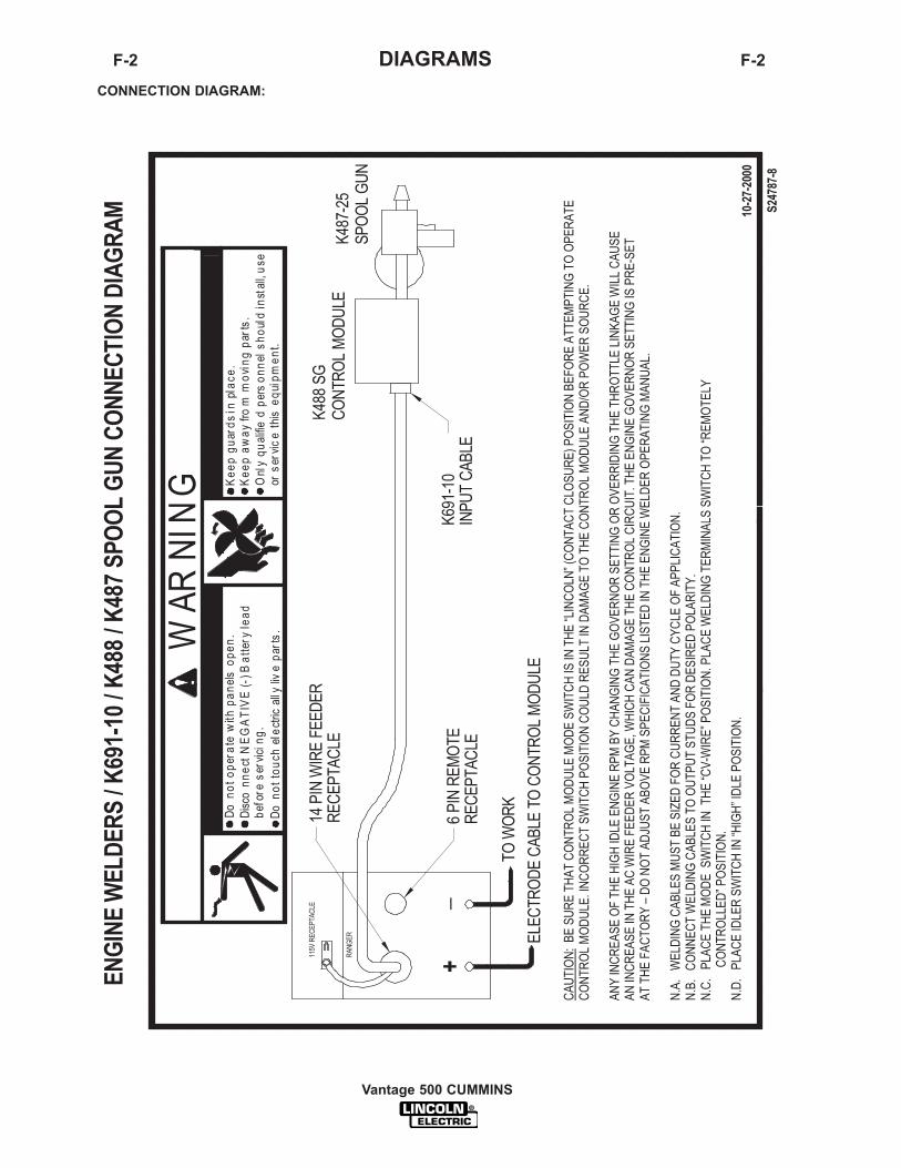
Vantage 500 CUMMINS
F-2 DIAGRAMS F-2
CONNECTION DIAGRAM:

F-3 DIAGRAMS F-3
Vantage 500 CUMMINS
CONNECTION DIAGRAM:
GN
D
75 76 77
GR
EE
N
K29
1O
RK
404
75
INP
UT
CA
BLE
76
N.E
.
77K
775
OP
TIO
NA
LR
EM
OTE
CO
NTR
OL
DAMA
GED.
THE
ENGI
NEGO
VERN
ORSE
TTIN
GIS
PRE-
SET
ATTH
EFA
CTOR
Y-D
ONO
TAD
JUST
ABOV
ERP
MSP
ECIF
ICAT
IONS
LISTE
DIN
81 42 41
3131
3232
22
44
2121
GN
D
82
N.D
.LN
-7W
IRE
FEE
DE
R
Keep
guar
dsin
plac
e.
CO
MM
AN
DE
R/
K86
7/
K77
5/
LN-7
CO
NN
EC
TIO
ND
IAG
RA
M
Keep
away
from
mov
ing
parts
.
WA
RN
ING
Onl
yqu
alifi
edpe
rson
nels
houl
din
stal
l,use
orse
rvic
eth
iseq
uipm
ent.
SPA
RE
Do
noto
pera
tew
ithpa
nels
open
.
7-20
00
S239
83
Dis
conn
ectN
EG
ATIV
E(-
)BAT
TER
YLE
AD
ELE
CT
RO
DE
ELE
CTR
OD
EC
AB
LETO
WIR
EFE
ED
UN
IT
K86
7U
NIV
ER
SA
L
AD
AP
TER
PLU
G
CAUT
ION
:
ANY
INCR
EASE
OFTH
EHI
GHID
LEEN
GINE
RPM
BYCH
ANGI
NGTH
EGO
VERN
ORSE
TTIN
GOR
OVER
RIDI
NGTH
ETH
ROTT
LELIN
KAGE
WILL
CAUS
EAN
INCR
EASE
INTH
ETH
EAC
AUXI
LIARY
VOLT
AGE.
IFTH
ISVO
LTAG
EGO
ESOV
ER14
0VOL
TS,W
IRE
FEED
ERCO
NTRO
LCIR
CUIT
SMA
YBE
THE
ENGI
NEW
ELDE
ROP
ERAT
ING
MANU
AL.
N.A
.W
ELD
ING
CA
BLE
MU
ST
BE
OF
PR
OP
ER
CA
PAC
ITY
FOR
THE
CU
RR
EN
TA
ND
DU
TYC
YC
LEO
FIM
ME
DIA
TEA
ND
FUTU
RE
AP
PIL
ICAT
ION
S.S
EE
OP
ER
ATIN
GM
AN
UA
L.
PLA
CE
WIR
EFE
ED
ER
SW
ITC
HTO
"WIR
EFE
ED
ER
WIT
HC
ON
TRO
LC
AB
LEP
OS
ITIO
N.
N.B
.U
SE
VOLT
ME
TER
SW
ITC
HTO
SE
LEC
TD
ES
IRE
DE
LEC
TRO
DE
PO
LAR
ITY.
PO
SIT
ION
THE
"SE
LEC
TOR
"SW
ITC
HTO
"WIR
EW
ELD
ING
CV
".
N.C
.IF
OP
TIO
NA
LR
EM
OTE
OU
TPU
TC
ON
TRO
LIS
US
ED,
CO
NTR
OL
ISAU
TOM
ATIC
ALL
YS
WIT
CH
ED
TOR
EM
OTE
CO
NTR
OL.
N.D
.IN
SU
LATE
EAC
HU
NU
SE
DLE
AD
IND
IVID
UA
LLY.
N.E
.S
PLI
CE
LEA
DS
AN
DIN
SU
LATE
.
}be
fore
serv
icin
g.
Do
nott
ouch
elec
trica
llyliv
epa
rts.
}
14P
INA
MP
HE
NO
L
TOW
OR
K
TOW
OR
K

F-4 DIAGRAMS F-4
Vantage 500 CUMMINS
CONNECTION DIAGRAM

Vantage 500 CUMMINS
F-5 DIAGRAMS F-5
CONNECTION DIAGRAM
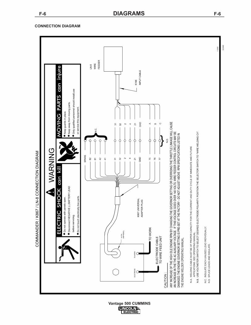
Vantage 500 CUMMINS
F-6 DIAGRAMS F-6
CONNECTION DIAGRAM
CAU
TIO
N:
N.A
.W
ELD
ING
CA
BLE
MU
ST
BE
OF
PR
OP
ER
CA
PAC
ITY
FOR
THE
CU
RR
EN
TA
ND
DU
TYC
YC
LEO
FIM
ME
DIA
TEA
ND
FUTU
RE
AP
PIC
ATIO
NS.
SE
EO
PE
RAT
ING
MA
NU
AL.
7532314142
N.C
.IN
SU
LATE
EAC
HU
NU
SE
DLE
AD
IND
IVID
UA
LLY.
N.D
.S
PLI
CE
LEA
DS
AN
DIN
SU
LATE
.
THE
ENGI
NEW
ELDE
ROP
ERAT
ING
MANU
AL.
GN
D
31 4 21 B CA
14P
INA
MP
HE
NO
L
TOW
OR
K
TOW
OR
KE
LEC
TRO
DE
TOW
IRE
FEE
DU
NIT
ELE
CTR
OD
EC
AB
LE
WIR
E
FEE
DE
R
K19
6K
867
UN
IVE
RS
AL
AD
AP
TER
PLU
GIN
PU
TC
AB
LE
S239
89
CO
MM
AN
DE
R/K
867
/LN
-8C
ON
NE
CTI
ON
DIA
GR
AM
7-20
00
2 4 76 77
ANY
INCR
EASE
OFTH
EHI
GHID
LEEN
GINE
RPM
BYCH
ANGI
NGTH
EGO
VERN
ORSE
TTIN
GOR
OVER
RIDI
NGTH
ETH
ROTT
LELIN
KAGE
WILL
CAUS
EAN
INCR
EASE
INTH
ETH
EAC
AUXI
LIARY
VOLT
AGE.
IFTH
ISVO
LTAG
EGO
ESOV
ER14
0VOL
TS,W
IRE
FEED
ERCO
NTRO
LCIR
CUIT
SMA
YBE
DAMA
GED.
THE
ENGI
NEGO
VERN
ORSE
TTIN
GIS
PRE-
SET
ATTH
EFA
CTOR
Y-D
ONO
TAD
JUST
ABOV
ERP
MSP
ECIF
ICAT
IONS
LISTE
DIN
N.B
.U
SE
VOLT
ME
TER
SW
ITC
HTO
SE
LEC
TD
ES
IRE
DE
LEC
TRO
DE
PO
LAR
ITY.
PO
SIT
ION
THE
SE
LEC
TOR
SW
ITC
HTO
"WIR
EW
ELD
ING
CV
".
SPA
RE
82
Onl
yqu
alifi
edpe
rson
nels
houl
din
stal
l,use
81
befo
rese
rvic
ing.
orse
rvic
eth
iseq
uipm
ent.
Keep
away
from
mov
ing
parts
.
N.C
.
Keep
guar
dsin
plac
e.
}D
isco
nnec
tNE
GAT
IVE
(-)B
ATTE
RY
LEA
D
Do
nott
ouch
elec
trica
llyliv
epa
rts.
21
Do
noto
pera
tew
ithpa
nels
open
.
GN
D
N.D
.
32 2
WA
RN
ING
}
LN-8

Vantage 500 CUMMINS
F-7 DIAGRAMS F-7
CONNECTION DIAGRAM

Vantage 500 CUMMINS
F-8 DIAGRAMS F-8
CONNECTION DIAGRAM

Vantage 500 CUMMINS
F-9 DIAGRAMS F-9
CONNECTION DIAGRAM
or s
ervi
ceth
iseq
uipm
ent.
Onl
yqu
alifi
edpe
rson
nel s
houl
d in
stal
l,use
Kee
paw
ay fr
omm
ovin
gpa
rts.
Kee
pgu
ards
inpl
ace.
MO
VIN
G P
AR
TS
can
inju
reW
ARN
ING
Do
nott
ouch
elec
trica
lly li
vepa
rts.
befo
re s
ervi
cing
.D
isco
nnec
t NE
GA
TIV
E (-
) Bat
tery
lead
Do
noto
pera
tew
ithpa
nels
open
.E
LEC
TR
IC S
HO
CK
can
kill
14 P
IN
AM
PH
EN
OL
TO W
OR
K
+_
EN
GIN
EW
ELD
ER
S /L
N-8
CO
NN
EC
TIO
ND
IAG
RA
M
S247
87-6
4-14
-200
0
TO L
N-8
INP
UT
CA
BLE
PLU
G
ELE
CTR
OD
E C
AB
LETO
WIR
E F
EE
D U
NIT
CA
UTI
ON
:
AN
Y IN
CR
EA
SE
OF
THE
HIG
H ID
LE E
NG
INE
RP
M B
Y C
HA
NG
ING
TH
E G
OV
ER
NO
R S
ETT
ING
OR
OV
ER
RID
ING
TH
E T
HR
OTT
LE L
INK
AG
E W
ILL
CA
US
EA
N IN
CR
EA
SE
IN T
HE
AC
WIR
E F
EE
DE
R V
OLT
AG
E, W
HIC
H C
AN
DA
MA
GE
TH
E C
ON
TRO
L C
IRC
UIT
. TH
E E
NG
INE
GO
VE
RN
OR
SE
TTIN
G IS
PR
E-S
ET
AT
THE
FA
CTO
RY
– D
O N
OT
AD
JUS
T A
BO
VE
RP
M S
PE
CIF
ICA
TIO
NS
LIS
TED
IN T
HE
EN
GIN
E W
ELD
ER
OP
ER
ATI
NG
MA
NU
AL.
N.A
. W
ELD
ING
CA
BLE
S M
US
T B
E O
F P
RO
PE
R C
AP
AC
ITY
FO
R T
HE
CU
RR
EN
T A
ND
DU
TY C
YC
LE O
F IM
ME
DIA
TE A
ND
FU
TUR
EA
PP
LIC
ATI
ON
S. S
EE
OP
ER
ATI
NG
MA
NU
AL.
N.B
. C
ON
NE
CT
WE
LDIN
G C
AB
LES
TO
OU
TPU
T S
TUD
S F
OR
DE
SIR
ED
PO
LAR
ITY
. PO
SIT
ION
TH
E W
IRE
FE
ED
ER
VO
LTM
ETE
R S
WIT
CH
TO
M
ATC
H T
HE
PO
LAR
ITY
OF
THE
ELE
CTR
OD
E C
AB
LE.
N.C
. P
LAC
E ID
LER
SW
ITC
H IN
“H
IGH
” PO
SIT
ION
.
K59
5 C
ON
TRO
L C
AB
LE

Vantage 500 CUMMINS
F-10 DIAGRAMS F-10
CONNECTION DIAGRAM
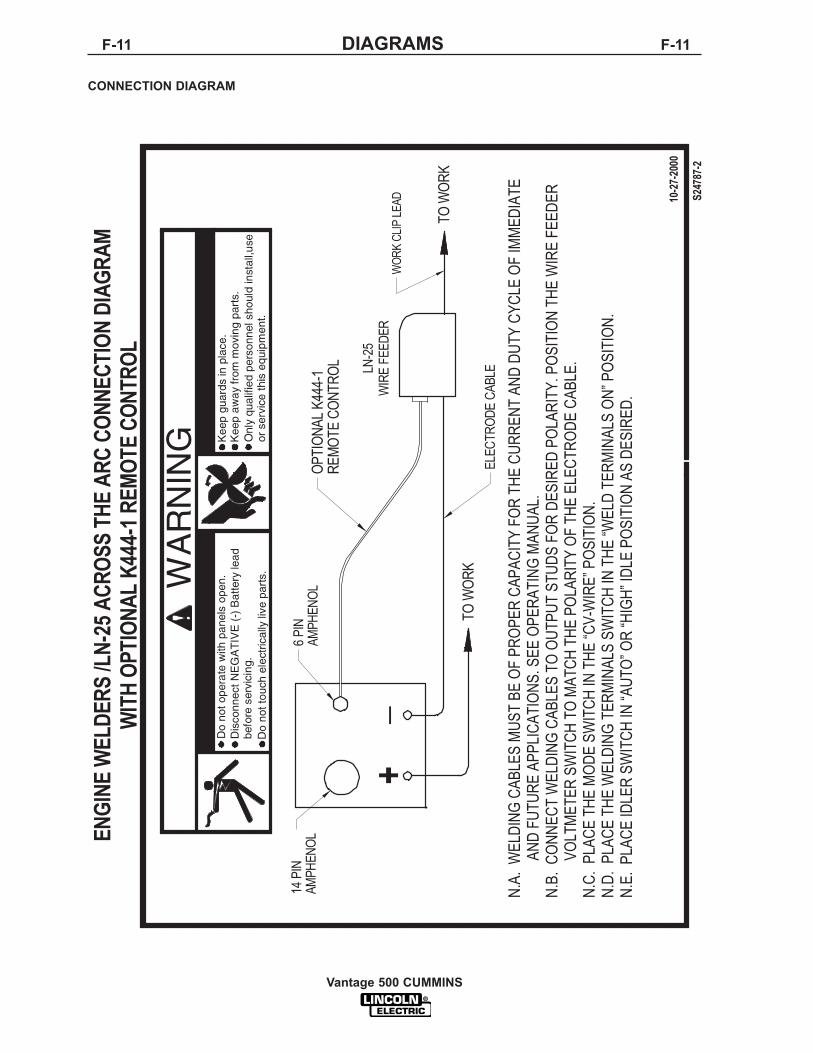
Vantage 500 CUMMINS
F-11 DIAGRAMS F-11
CONNECTION DIAGRAM

Vantage 500 CUMMINS
F-12 DIAGRAMS F-12
CONNECTION DIAGRAM

Vantage 500 CUMMINS
F-13 DIAGRAMS F-13
CONNECTION DIAGRAM
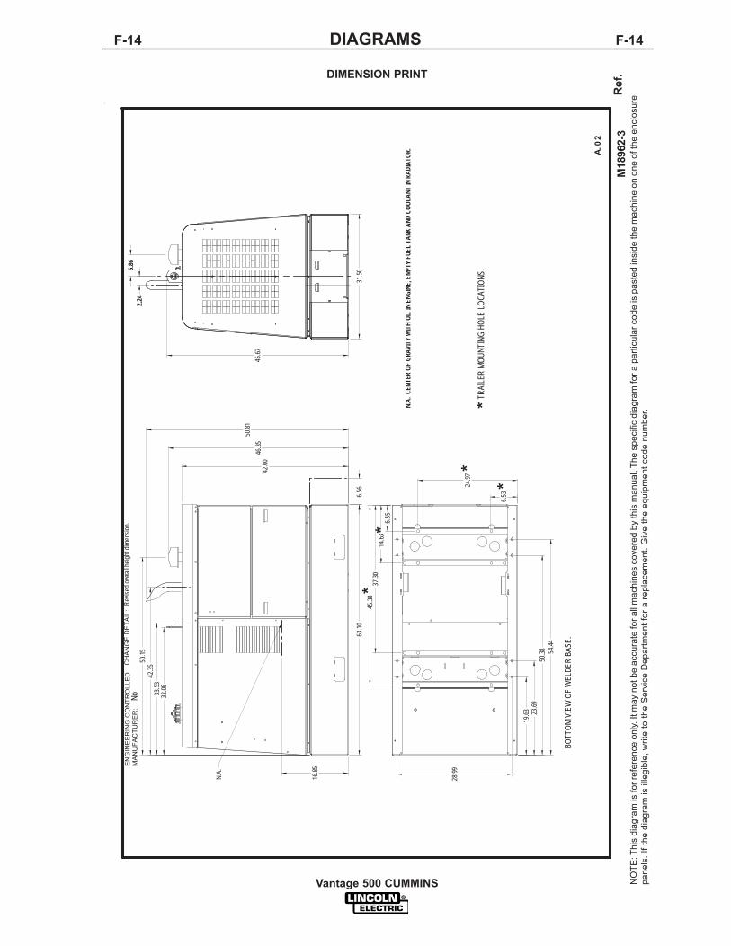
Vantage 500 CUMMINS
F-14 DIAGRAMS F-14
DIMENSION PRINT
TRA
ILE
R M
OU
NTI
NG
HO
LELO
CA
TIO
NS
.*
28.9
9
19.6
3
6.55
23.6
950
.38 54
.44
14.6
337
.30
45.3
8
63.1
06.
56
42.0
0
50.8
1
16.8
5
33.5
332
.08
42.3
5
31.5
0
45.6
7
2.24
50.1
5
5.86
46.3
5
*
*
*
*
BO
TTO
M V
IEW
OF
WE
LDE
R B
AS
E.
N.A
.C
EN
TER
OF
GR
AV
ITY
WIT
H O
IL IN
EN
GIN
E, E
MP
TY F
UE
L TA
NK A
ND
CO
OLA
NT
INR
AD
IATO
R.
N.A
.
M18
962-
3
EN
GIN
EE
RIN
G C
ON
TRO
LLE
DM
AN
UFA
CTU
RE
R:
No
A.0
2
Rev
ised
ove
rall
heig
ht d
imen
sion
.C
HA
NG
E D
ETA
IL:
6.53
24.9
7
NO
TE: T
his
diag
ram
is fo
r ref
eren
ce o
nly.
It m
ay n
ot b
e ac
cura
te fo
r all
mac
hine
s co
vere
d by
this
man
ual.
The
spec
ific
diag
ram
for a
par
ticul
ar c
ode
is p
aste
d in
side
the
mac
hine
on
one
of th
e en
clos
ure
pane
ls. I
f the
dia
gram
is il
legi
ble,
writ
e to
the
Ser
vice
Dep
artm
ent f
or a
repl
acem
ent.
Giv
e th
e eq
uipm
ent c
ode
num
ber.
Ref
.

Vantage 500 CUMMINS
WARNING
AVISO DEPRECAUCION
ATTENTION
WARNUNG
ATENÇÃO
Spanish
French
German
Portuguese
Japanese
Chinese
Korean
Arabic
READ AND UNDERSTAND THE MANUFACTURER’S INSTRUCTION FOR THIS EQUIPMENT AND THE CONSUMABLES TOBE USED AND FOLLOW YOUR EMPLOYER’S SAFETY PRACTICES.
SE RECOMIENDA LEER Y ENTENDER LAS INSTRUCCIONES DEL FABRICANTE PARA EL USO DE ESTE EQUIPO Y LOSCONSUMIBLES QUE VA A UTILIZAR, SIGA LAS MEDIDAS DE SEGURIDAD DE SU SUPERVISOR.
LISEZ ET COMPRENEZ LES INSTRUCTIONS DU FABRICANT EN CE QUI REGARDE CET EQUIPMENT ET LES PRODUITS AETRE EMPLOYES ET SUIVEZ LES PROCEDURES DE SECURITE DE VOTRE EMPLOYEUR.
LESEN SIE UND BEFOLGEN SIE DIE BETRIEBSANLEITUNG DER ANLAGE UND DEN ELEKTRODENEINSATZ DESHERSTELLERS. DIE UNFALLVERHÜTUNGSVORSCHRIFTEN DES ARBEITGEBERS SIND EBENFALLS ZU BEACHTEN.
l Do not touch electrically live parts orelectrode with skin or wet clothing.
l Insulate yourself from work andground.
l No toque las partes o los electrodosbajo carga con la piel o ropamojada.
l Aislese del trabajo y de la tierra.
l Ne laissez ni la peau ni desvêtements mouillés entrer en contactavec des pièces sous tension.
l Isolez-vous du travail et de la terre.
l Berühren Sie keine stromführendenTeile oder Elektroden mit IhremKörper oder feuchter Kleidung!
l Isolieren Sie sich von denElektroden und dem Erdboden!
l Não toque partes elétricas eelectrodos com a pele ou roupamolhada.
l Isole-se da peça e terra.
l Keep flammable materials away.
l Mantenga el material combustiblefuera del área de trabajo.
l Gardez à l’écart de tout matérielinflammable.
l Entfernen Sie brennbarres Material!
l Mantenha inflamáveis bemguardados.
l Wear eye, ear and body protection.
l Protéjase los ojos, los oídos y elcuerpo.
l Protégez vos yeux, vos oreilles etvotre corps.
l Tragen Sie Augen-, Ohren- und Kör-perschutz!
l Use proteção para a vista, ouvido ecorpo.

Vantage 500 CUMMINS
WARNING
AVISO DEPRECAUCION
ATTENTION
WARNUNG
ATENÇÃO
Spanish
French
German
Portuguese
Japanese
Chinese
Korean
Arabic
LEIA E COMPREENDA AS INSTRUÇÕES DO FABRICANTE PARA ESTE EQUIPAMENTO E AS PARTES DE USO, E SIGA AS PRÁTICAS DE SEGURANÇA DO EMPREGADOR.
l Keep your head out of fumes.l Use ventilation or exhaust to
remove fumes from breathing zone.
l Los humos fuera de la zona derespiración.
l Mantenga la cabeza fuera de loshumos. Utilice ventilación oaspiración para gases.
l Gardez la tête à l’écart des fumées.l Utilisez un ventilateur ou un
aspirateur pour ôter les fumées deszones de travail.
l Vermeiden Sie das Einatmen vonSchweibrauch!
l Sorgen Sie für gute Be- undEntlüftung des Arbeitsplatzes!
l Mantenha seu rosto da fumaça.l Use ventilação e exhaustão para
remover fumo da zona respiratória.
l Turn power off before servicing.
l Desconectar el cable dealimentación de poder de lamáquina antes de iniciar cualquierservicio.
l Débranchez le courant avantl’entretien.
l Strom vor Wartungsarbeitenabschalten! (Netzstrom völligöffnen; Maschine anhalten!)
l Não opere com as tampas removidas.l Desligue a corrente antes de fazer
serviço.l Não toque as partes elétricas nuas.
l Do not operate with panel open orguards off.
l No operar con panel abierto oguardas quitadas.
l N’opérez pas avec les panneauxouverts ou avec les dispositifs deprotection enlevés.
l Anlage nie ohne Schutzgehäuseoder Innenschutzverkleidung inBetrieb setzen!
l Mantenha-se afastado das partesmoventes.
l Não opere com os paineis abertosou guardas removidas.

World’s Leader in Welding and Cutting Products• Sales and Service through Subsidiaries and Distributors Worldwide •
Cleveland, Ohio 44117-1199 USA Tel: 216.481.8100 Fax: 216.486.1751 Web Site: www.lincolnelectric.com