vanderbilt university office of space & facilities planning · 1.5 valve and equipment ... 8.1...
TRANSCRIPT
Patient Care FacilityMechanical Design Guidelines
And Construction StandardsVUMC 06/21/13
OVanderbilt
Vanderbilt UniversityOffice of Space & Facilities Planning
MECHANICAL DESIGN GUIDELINESAND CONSTRUCTION STANDARDS
Date of Current Issue:June 2013
1
Patient Care FacilityMechanical Design Guidelines
And Construction StandardsVUMC 06/21/13
Contents
1. General Provisions1.1 General1.2 Mechanical Drawings, Diagrams and Sketches1.3 Demolition1.4 Pipe Identification1.5 Valve and Equipment Identification1.6 Equipment and Systems Testing1.7 Inspections
2. Piping Specialties2.1 Steel Pipe2.2 Copper Pipe2.3 Cast Iron Soil and Vent Pipe2.4 Plastic Pipe2.5 Concrete Pipe2.6 Installation of Piping2.7 Valves2.8 Medical Gas Piping
3. Motors and Drives
4. Vibration Isolation4.1 Floor Mounted Spring Isolators4.2 Spring Rubber Hangers4.3 Rubber Neoprene Pads4.4 Spring and Rubber Isolator Hangers4.5 Flexible Pipe Connectors
5. Insulation5.1 General Requirements5.2 Duct Insulation5.3 Piping Insulation5.4 Equipment Insulation
6. Fire Protection
7. Plumbing Systems7.1 General Requirements7.2 Backflow Preventers7.3 Floor Drains and Trap Primers7.4 Cleanouts7.5 Natural Gas Connections7.6 Acid Waste Piping and Equipment7.7 Deionized/Distilled Water Piping and Equipment7.8 Domestic Water Systems7.9 Plumbing Fixtures
2

8. Medical and Lab Gas Systems8.1 General Requirements8.2 Medical Gas Alarm System8.3 Piping Materials8.4 Medical/Lab Vacuum Pumps8.5 Medical/Lab Air Compressors
Patient Care FacilityMechanical Design Guidelines
And Construction StandardsVUMC 06/21/13
9. Water Systems9.1 HVAC Pumps9.2 Hydronic Specialties9.3 Chemical Water Treatment9.4 Chillers9.5 Cooling Towers9.6 Hot Water Heating Coils
10. Steam Producing and Management Equipment10.1 Steam and Condensate Specialties10.2 Humidifiers10.3 Steam Heating Coils10.4 Boilers10.5 Condensate Return Pump
11. Air Side Equipment11.1 Air Handling Units11.2 Fan Coil Units11.3 Air Terminal Units11.4 Fans11.5 Filters11.6 Unit Heaters11.7 Electric Duct Heaters
12. Sheetmetal Ductwork and Accessories12.1 Duct Construction and Installation12.2 Accessories
13. Controls and Facilities Management System
14. HVAC Systems Test and Balance
15. Specific Space Requirements and Design Criteria15.1 General Design Criteria15.2 General Laboratory15.3 Biosafety Level 3 (BL-3) Laboratory15.4 Patient Room
General Patient RoomInfectious Isolation Room (TB)Protective Isolation Room (Myelo)
15.5 Operating Room15.6 Cath. Lab15.7 Nuclear Medicine Suite15.8 MRI Suite15.9 Linear Accelerator Suite
3

Patient Care FacilityMechanical Design Guidelines
And Construction StandardsVUMC 06/21/13
15.10 Animal Care Area15.11 Autopsy and Morgue15.12 Vanderbilt Hospital and The Vanderbilt Clinic15.13 Pharmacy Spaces
16. Energy Efficiency and Conservation Requirements16.1 General Design Criteria16.2 Building Envelope Requirements16.3 Minimum Motor Efficiencies16.4 Miscellaneous Energy Efficiency Requirements16.5 Commissioning
17. Mechanical and Plumbing Details17.1 Mechanical Detail Index Reference to Appendix A17.2 Plumbing Details Index Reference to Appendix A
18. O&M Closeout Documentation Requirements
Appendix A Mechanical and Plumbing Details
Appendix B BSL-3 Laboratory Design Schematic
4

Patient Care FacilityMechanical Design Guidelines
And Construction StandardsVUMC 06/21/13
Chapter
IGeneral Provisions
1.1 General
Content displayed in a red font represents information that has been added or revised since thelast issue of these standards.
This document shall serve as minimum requirements for design and construction of mechanicalsystems for all Vanderbilt University Medical Center "patient care" buildings, both new andexisting. Any design or construction not meeting or exceeding these minimum standardsrequires specific approval from the Office of Space and Facilities Planning.
Mechanical work includes plumbing, sprinkler, medical gas systems, controls, insulation,heating, ventilating, and air conditioning systems.
The design and installation of mechanical systems shall comply with state and local healthdepartments, environmental protection agency, and building codes, including plumbing codes,and with state and local ordinances.
Ductwork construction, installation and ventilation systems shall comply with NFPA Standard90A and SMACNA.
Sprinkler systems shall comply with NFPA Standard 13 and 14.
Equipment shall be U.L. Listed and labeled as required in specific equipment chapters.Installation of systems shall comply with U.L. standards, where applicable.
Piping, fittings and valves shall be provided by domestic manufactures, unless specificallyapproved prior to installation. Where appropriate, components shall be marked clearly with themanufacturer's name, weight and classification or working pressure.
Fittings, valves, and piping specialties shall be the products of a single manufacturer. Toolsused for pipe preparation and/or installation shall be of the same manufacturer as the pipingcomponents.
The completed project shall pass any and all tests required by the authorities having jurisdiction.
Mechanical equipment shall comply with regulatory noise and safety standards.
Mechanical systems and equipment shall be guaranteed against faulty material or workmanshipfor a period of not less than one year from the date of substantial completion or acceptance bythe project commissioning agent or beneficial use, whichever date is the latest.
5

Patient Care FacilityMechanical Design Guidelines
And Construction StandardsVUMC 06/21/13
Counter flash ducts, pipes and conduits where penetration of roofs or outside walls occur.
Do not route any piping or ductwork directly above or within 42 inches in front of electricalswitchgear, panels or transformers.
Mechanical room floors, of Vanderbilt owned buildings, located on the lowest floor lever shouldbe provided with a standard floor sealer, rather than a painted surface. Mechanical room floorslocated above occupied spaces should be finished with a Dex-o-tex or equivalent waterproofflooring. This includes floor areas under mechanical equipment. The floor under mechanicalequipment shall be coated prior to equipment placement. The remainder of the equipment roomfloor shall be coated after all equipment is set in place.
Ductwork and piping located outside shall be provided with a means of weather-proofing.
Grooved joint couplings and fittings shall be shown on drawings and product submittals andshall be specifically identified with the applicable Victaulic style or series designation.The construction manager shall include provisions for updating the fire/smoke commanddocuments, which are kept in the fire command rooms, when renovation work makesmodifications to a buildings fire/smoke zones.
1.2 Mechanical Drawings, Diagrams and Sketches
The design engineer shall provide a Basis of Design document to VUMC prior to the CD phaseof the project when the design makes significant changes to systems or infrastructure of thebuilding. Significant changes shall be defined by any of following project characteristics:
1. A project that adds any equipment with motor HP's greater than 10-hp.2. Changes in how the building control systems function, such as lab control concepts.3. Changes in fire protection infrastructure, other than redistribution of sprinkler piping.4. A project that adds new systems to the building, such as an acid dilution tank or other
equipment that requires routine maintenance/inspection by Plant Services.5. Any project where LEED accreditation is being pursued, regardless of whether or not the
LEED strategy includes enhanced commissioning.
Drawings representing Division 15 disciplines, Mechanical, Plumbing, Medical Gas and FireProtection, shall be identified according to the following nomenclature:First Digit(s) Represents the discipline
> M Mechanical> MP- Mechanical Piping> MS Mechanical/Plumbing Site> P Plumbing> MG Medical Gas> FP Fire Protection
Second Digit Represents the content series> 0 General Notes, Schedules, Legends, Specifications, etc.> 1 Demolition Work> 2 Base Scale New Construction Plans> 3 Large Scale New Construction Plans> 4 Sections
6

Patient Care FacilityMechanical Design Guidelines
And Construction StandardsVUMC 06/21/13
> 5 Details> 6 Controls> 7 Riser Diagrams
Third Digit Represents the floor level depicted> B Basement> 1 First Floor> 2 Second Floor> M Mezzanine> P Penthouse> R Roof> 0 No Floor Designation, i.e. details, controls, risers, etc.
Fourth Digit Represent the numerical order> 1 First sheet of the given series> 2 Second sheet of the given series, etc.
A dash "-" should separate the second and third digits and a period "." should separate the thirdand fourth digits.
Examples:
M2-3.2 This sheet would be the second base scale mechanical plan of the third floor.
P4-0.3 This sheet would be the third plumbing detail sheet.
These drawing designations should serve as the general guideline. If the space allows thedetails and controls may be included in the 0 series sheets. Likewise, if appropriate the medicalgas and fire protection may be included on the P discipline sheets.
1.3 Demolition
Remove abandoned ductwork, duct straps, hangers, and supports, either associated with newwork or previously abandoned.
Remove abandoned piping, hangers and supports. Provide shut-off valves and cap piping asnear to the mains as possible.
All existing or new holes in slabs and fire or smoke rated walls will be patched, with a fire/waterproof sealant, to match the existing structure.
Refer to Chapter 14, HVAC SYSTEMS TEST AND BALANCE for pre-demolition balancingrequirements.
Should any asbestos be identified within the renovation area, the architect, engineer and ownershould be notified before continuing work.
7

Patient Care FacilityMechanical Design Guidelines
And Construction StandardsVUMC 06/21/13
1.4 Pipe Identification
All piping for any service shall be identified as to their service after application of insulationand/or final painting, by color code banding and stenciling, (refer to Table 1 below).Medical/Lab gas piping color-coding is based on the current NFPA-99 standards. Should theNFPA-99 color coding schemes change, the most current coloring standards shall be followed.Marking shall indicate pipe content and direction of fluid flow. All markers to be stenciled inpositions visible to personnel. Paint pipe content banding, legend and flow direction marker ateach valve, at least once in each separate space through which the pipe passes, on each riserand tee joint, and at 25 foot intervals on long continuous runs of pipe. Arrows (flow directionmarkers) shall point away from content marking and in direction of flow. If flow can be in bothdirections, apply double-headed arrows.
In addition to identifying piping, stencil design-operating pressure in psig on steam and gravitycondensate return piping.
Table 1Pipe Identification:
ServiceSprinkler
Color CodeBackground LetteringSafety Red White
Natural Gas Yellow BlackNitrogen Black WhiteNitrous Oxide Blue WhiteMedical Air Yellow BlackMedical Vacuum White BlackOxygen Green WhiteCarbon Dioxide Gray WhiteLaboratory Air Yellow & White Checkerboard BlackLaboratory Vacuum White & Black Checkerboard Black Boxed
Steam Yellow BlackCondensate Return Yellow Black
Heating Hot Water Yellow BlackDomestic Hot Water Yellow BlackDomestic Cold Water Green BlackChilled Water Green BlackCondenser Water Green Black
Rain Water Green WhiteWaste Yellow BlackVent Yellow Black
Identification of gases not included in Table 1 shall conform to NFPA-99 and the CompressedGas Association (CGA) Publication C-9
8
Patient Care FacilityMechanical Design Guidelines
And Construction StandardsVUMC 06/21/13
The color band width for outside diameter of insulated pipe and/or uninsulated pipe shall be asfollows:
Pipe Diameter Band/Label Width3/4" to 2" 8"
2 1/2" to 6" 12"8" to 10" 24"
10" and up 32"
The stenciling letter height shallPipe Diameter
be as follows:Letter Height
1/2" to 11/4"1 1/2" to 2" 34"
2 1/2" to 6" 1 1/4"
8" to 10" 2 1/2"
Over 10" 3 va"
Control compressed air and buried lines are not to be stenciled.
Pipe Markers may be used on piping in lieu of painting bands and stenciling to identify piping.The same color and size requirements shall apply.
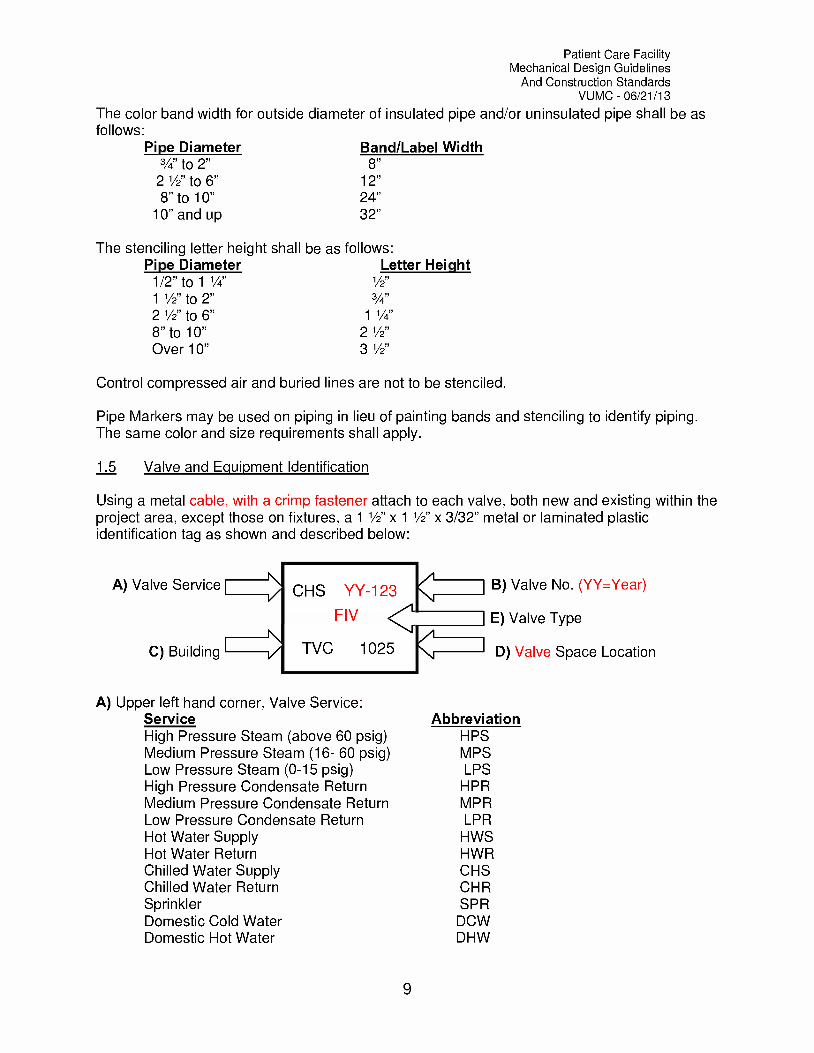
1.5 Valve and Equipment Identification
Using a metal cable, with a crimp fastener attach to each valve, both new and existing within theproject area, except those on fixtures, a 1 1/2" x 1 1/2" x 3/32" metal or laminated plasticidentification tag as shown and described below:
A) Valve Service
C) Building
B) Valve No. (YY=Year)
E) Valve Type
D) Valve Space Location
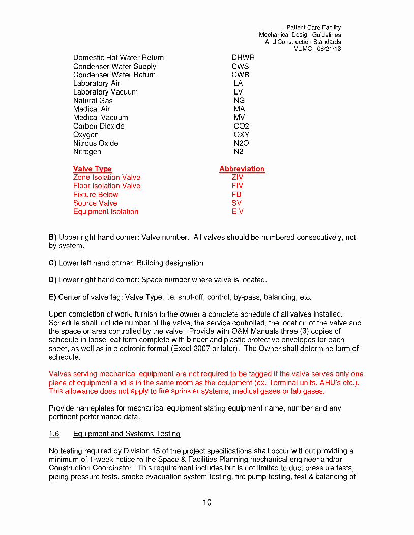
A) Upper left hand corner, Valve Service:Service AbbreviationHigh Pressure Steam (above 60 psig) H PSMedium Pressure Steam (16- 60 psig) MPSLow Pressure Steam (0-15 psig) LPSHigh Pressure Condensate Return H PRMedium Pressure Condensate Return MPRLow Pressure Condensate Return LPRHot Water Supply HWSHot Water Return HWRChilled Water Supply CHSChilled Water Return CH RSprinkler SPRDomestic Cold Water DCWDomestic Hot Water DHW
9
Patient Care FacilityMechanical Design Guidelines
And Construction StandardsVUMC 06/21/13
Domestic Hot Water Return DHWRCondenser Water Supply CWSCondenser Water Return CWRLaboratory Air LALaboratory Vacuum LVNatural Gas NGMedical Air MAMedical Vacuum MVCarbon Dioxide CO2Oxygen OXYNitrous Oxide N20Nitrogen N2
Valve Type AbbreviationZone Isolation Valve ZIVFloor Isolation Valve FIVFixture Below FBSource Valve SVEquipment Isolation E IV
B) Upper right hand corner: Valve number. All valves should be numbered consecutively, notby system.
C) Lower left hand corner: Building designation
D) Lower right hand corner: Space number where valve is located.
E) Center of valve tag: Valve Type, i.e. shut-off, control, by-pass, balancing, etc.
Upon completion of work, furnish to the owner a complete schedule of all valves installed.Schedule shall include number of the valve, the service controlled, the location of the valve andthe space or area controlled by the valve. Provide with O&M Manuals three (3) copies ofschedule in loose leaf form complete with binder and plastic protective envelopes for eachsheet, as well as in electronic format (Excel 2007 or later). The Owner shall determine form ofschedule.
Valves serving mechanical equipment are not required to be tagged if the valve serves only onepiece of equipment and is in the same room as the equipment (ex. Terminal units, AHU's etc.).This allowance does not apply to fire sprinkler systems, medical gases or lab gases.
Provide nameplates for mechanical equipment stating equipment name, number and anypertinent performance data.
1.6 Equipment and Systems Testing
No testing required by Division 15 of the project specifications shall occur without providing aminimum of 1-week notice to the Space & Facilities Planning mechanical engineer and/orConstruction Coordinator. This requirement includes but is not limited to duct pressure tests,piping pressure tests, smoke evacuation system testing, fire pump testing, test & balancing of
10
Patient Care FacilityMechanical Design Guidelines
And Construction StandardsVUMC 06/21/13
mechanical systems, required medical gas tests, etc. Any testing performed without providingthe required notice may result in the contractor being required to retest the equipment and/orsystem at his own expense.
1.7 Inspections
When appropriate the contractor shall schedule and attend inspections by Space and FacilitiesPlanning and Plant Services prior to owner acceptance and completion of construction. Theseinspections include Underground Utilities, In-wall Inspections, Above Ceiling Inspections andFinal Inspections. The contractor should obtain signed acceptance from Space and FacilitiesPlanning and the appropriate Plant Services shop managers before this work is consideredcomplete.
11
Patient Care FacilityMechanical Design Guidelines
And Construction StandardsVUMC 06/21/13
Chapter
2Piping Specialties
2.1 Steel Pipe
Use schedule 40 black steel piping for the following services:Chilled water supply and return piping larger than 2" diameterCondenser water supply and return pipingHVAC reheat water piping larger than 2" diameterFuel oil piping above groundFire Sprinkler piping (Schedule 10 may be allowed in buildings leased by Vanderbilt)Natural gas pipingPropane pipingHydronic heat pump supply and return piping larger than 2" diameter
Use schedule 40 seamless for the following services:Steam Piping
Use schedule 80 seamless for the following services:Steam condensate pipingBoiler blow down piping
Use schedule 40 galvanized pipe for the following services:Cooling coil condensate drain pipingWaste, vent and drain piping 1-1/2" diameter and smallerNon-insulated piping located outside exposed to weather
2.2 Copper Pipe
Use Type L, hard for the following services:Domestic hot water and recirculating pipingDomestic cold waterHVAC reheat water piping 2" and lessHVAC chilled water pipe 2" and lessHydronic heat pump supply and return piping 2" and less
Use Type L, ARC hard copper for the following services:Refrigeration piping liquid and hot gas lines
Use Type K, rolled, soft for the following services:Piping installed under floor slabs
12

Patient Care FacilityMechanical Design Guidelines
And Construction StandardsVUMC 06/21/13
Use Type M, hard for the following services:Non-pressurized drain, waste and vent piping
The Pro-Press method of joining copper piping and fittings may be utilized for pipe sizes up toand including 4", with prior approval of Space and Facilities Planning.
Any copper pipe larger than 2 1/2" shall be brazed, soft solder is not acceptable.
2.3 Cast Iron Soil and Vent Pipe
Use standard weight pipe with drainage fittings for the following services:Waste, vent and drainage pipe 2" and largerStorm WaterRainwater leaders inside buildingDrain lines under building or exterior concrete or paving. Extend cast iron piping aminimum of 5 feet outside of building.
Provide heavy-duty bands on all cast iron fittings.
2.4 Plastic Pipe
Polyvinyl Chloride (PVC) piping:PVC piping shall not be used for any water service inside of Vanderbilt ownedbuildings.Schedule 40 PVC piping may be used for outside gravity, underground sanitarysewer drainage piping.PVC may be used for above grade sanitary waste and vent piping in VanderbiltLeased buildings.
Polypropylene (PP) piping:Provide for acid waste, vent piping and fittingsPP piping shall have fusel and/or mechanical coupling jointsProvide for Deionized/Distilled water piping and fittings
2.5 Concrete Pipe
Use concrete pipe for the following services:Exterior underground sanitary sewersExterior underground storm sewers
2.6 Stainless Steel Pipe
Schedule 5S stainless steel pipe with Vic-Press 304TM fittings may be used in lieu of solderedcopper or threaded steel for sizes 2" and smaller in the following services, with prior permissionfrom Space and Facilities Planning:
HVAC condenser waterFuel oil piping above groundHVAC reheat water piping 2" and lessHVAC chilled water pipe 2" and less
13

Patient Care FacilityMechanical Design Guidelines
And Construction StandardsVUMC 06/21/13
Hydronic heat pump supply and return piping 2" and lessCooling coil condensate drain pipingDomestic hot water and recirculating pipingDomestic cold water
Stainless steel piping may be used in lieu of copper for piping 2 1/2" and larger with priorapproval from the VUMC Office of Space & Facilities Planning.
2.7 Installation of piping
Tee drilled fittings are not permitted in Vanderbilt owned buildings. This includes piercing valvesand saddle taps (other than Victaulic or equal).
Mechanical coupled joints are permitted with prior permission from Space and FacilitiesPlanning for HVAC, plumbing, or any other dynamic systems, as specified in Section 2.10.
Chrome pipe escutcheons shall be provided where pipe passing through finished walls may bevisible.
Do not install water pipes in electric rooms, telephone rooms, transformer rooms or elevatorequipment rooms, unless piping serves that space.
Slope drainage piping at a minimum 1/8" per linear foot.
Slope steam pipes and steam condensate drain pipes at a minimum of 1/4" per 10 feet.
Use expansion loops or expansion joints where necessary to provide for thermal expansion ofpiping. Where mechanical coupling piping systems are used, Install an adequate number ofVictaulic Style 77 flexible couplings on all expansion loops to accommodate thermal growth.
Pipe hangers shall be adjustable steel hangers with all-thread support rods.
Provide sufficient pipe hangers to support piping such that piping does not sag. Provide no lessthan one hanger per space that pipes pass through.
The maximum "on-center" hanger spacing allowed shall be as follows:Steel Pipe
1/4" to 1 1/2" 7'-0"2" to 2 1/2" 10'-0"3" to 4" 12'-0"4" and up -14'-0"
Copper Pipe1/4" to 1 1/4" 5'-0"2" to 2 1/2" 8'-0"3" and up 10'-0"
Cast Iron PipeAll sizes 8'-0"
PVC/PolypropyleneFollow manufacturer's recommendations.
14

Patient Care FacilityMechanical Design Guidelines
And Construction StandardsVUMC 06/21/13
Hangers shall be sized to support piping on the outside of insulation.
Provide 18 gauge saddles between hanger and pipe insulation.
Provide sleeves for piping installed at floors and rated walls and/or partitions as required below:Provide schedule 10 or 40 black steel for sleeves.Extend sleeves at least 2" above finished floor and/or wall.Ensure sleeves are provided at rated partitions/walls and floors in accordance withthe rated fire separation requirements.All insulated piping passing through fire and/or smoke rated partitions shall besleeved. The void space between pipe and sleeve shall be sealed fire, smoke andwatertight.
Provide chain operators for gate valves, butterfly valves and plug cocks larger than 3" located inequipment rooms and installed higher than 6'-0" above the finished floor.
Dielectric unions shall be used wherever dissimilar metals subject to galvanic activity are joinedtogether such as equipment connections between copper pipe and steel pipe.
Taps in pipes should be made on the top of mains when possible.
2.8 Valves
Steam valves shall be rated to operate at the system pressure plus 100°F superheat, (i.e. 125#steam valve must be rated for 450°F).
Provide shutoff valves with connecting unions, grooved joint couplings, or flanges on each pieceof HVAC or plumbing equipment to allow equipment to be isolated from the piping system.
Provide air vents at the highest point of each piece of equipment, including terminal reheatboxes.
Furnish valves in HVAC circulating water piping to isolate each floor or main section of thebuilding.
Avoid the use of reverse return piping systems.
2.9 Medical Gas Piping
Refer to Chapter 8 for Medical Gas Piping requirements.
2.10 Grooved Joint Couplings and Fittings
Grooved joint coupling piping systems may be used with prior permission from Space andFacilities Planning.
15
Patient Care FacilityMechanical Design Guidelines
And Construction StandardsVUMC 06/21/13
Couplings shall be manufactured of two ductile iron housing segments, elastomer pressureresponsive gasket and zinc electroplated steel bolts and nuts.
Steel Pipe:
2-1/2" through 12":Rigid Type: Housing cast with offsetting angle-pattern bolt pads to provide rigidity andsystem support and hanging in accordance with ANSI B31.1 and B31.9. Victaulic Style07.
Flexible Type: Use in locations where vibration attenuation and stress relief are required.Victaulic Style 75.
Copper Tubing: Couplings shall include Flush Seal gasket, with housing cast with offsettingangle-pattern bolt pads. Victaulic Style 606.
Fittings shall be manufactured from wrought copper in accordance with ASTM B75 orB152 and ANSI B16.22, or bronze sand cast in accordance with ASTM B584 and ANSIB16.18. Victaulic CTS.
Grooved fittings and couplings for hard copper tubing shall be manufactured to copper-tube dimensions. Flaring of tube or fitting ends to IPS sizes is not permitted.
All installers of mechanical coupling fittings must be certification in accordance with themanufacturer's requirements/recommendation. Proof of certification shall be submitted with theproduct submittal package.
16
Patient Care FacilityMechanical Design Guidelines
And Construction StandardsVUMC 06/21/13
Chapter
3Motors and Drives
Refer to the Vanderbilt University Medical Center Electrical Standards and Design Guidelinesfor additional motor and drive requirements.
Single-phase motors shall be:Capacitor startOpen drip-proof typeBall bearingInternal overloadRated at 40°C continuous rise
Polyphase motors to be:NEMA Design BNormal starting torqueSingle or two speedSquirrel cage typeOpen drip-proofInsulation for rating of 65°C continuous riseBall bearings rated for minimum B-10 life of 100,000 hoursFitted with grease fittings and relief parts
Motors furnished as a part of mechanical equipment shall be sized with a 1.15 service factor.Coordinate service factors for all motors with electrical engineer.
Refer to Chapter 16 "Energy Efficiency and Conservation Requirements" for minimum motorefficiency requirements.
All motors 15-hp and above, which function at varying pressures or flows shall be equipped witha variable frequency drive (VFD).
Motors specified with variable frequency drive controllers shall be inverter (VFD) duty rated.These motors shall be provided with an aegis grounding ring.
Motors provided in hazardous locations shall be explosion-proof.
Variable frequency motor drives (VFD's) shall have a minimum power factor of 0.95 and anefficiency of 95% at 100% full load output.
Do not specify a single VFD with bypass contactor and transfer switch for redundant equipmentsuch as pumps. Each piece of equipment must have its' own VFD.
17
Patient Care FacilityMechanical Design Guidelines
And Construction StandardsVUMC 06/21/13
When fan wall technology is used on air handling units, return fan systems or exhaust fansystems, the largest motor horse power shall not exceed 10-hp, unless the manufacturerprovides a motor removal system as an accessory to the unit.
18
Patient Care FacilityMechanical Design Guidelines
And Construction StandardsVUMC 06/21/13
Chapter
4Vibration Isolation
All motorized equipment, whether hung from the structure or floor mounted, will be provided witha vibration isolation device.
4.1 Floor Mounted Spring Isolators
Provide floor mounted spring isolators (Mason Type SLF or equal) for the following equipment:Control/Clinical Air CompressorsAir Conditioning Units, unless furnished with internal isolatorsVacuum PumpsCentrifugal Fans, unless provided with an inertia baseHVAC Pumps, unless provided with an inertia base
Provide floor mounted spring isolators with vertical stops (Mason Type SLR or equal) for thefollowing equipment:
Chillers
4.2 Spring Rubber Hangers
Provide spring rubber hangers (Mason Type HS or equal) for the following equipment:Ceiling suspended fansCeiling suspended air handling unitsOther motorized equipment hung from the structure.
4.3 Rubber Neoprene Pads
Provide rubber neoprene pads (Mason Super W or equal) for the following equipment, whenmounted on grade:
HVAC PumpsDomestic Water Booster PumpChillers
4.4 Spring and Rubber Isolator Hangers
Provide spring and rubber hangers (Mason PC3ON or equal) on piping, as required to limitvibration transmission from pumps, air handling units and compressors.
4.5 Flexible Pipe Connectors
Provide Mason Industries Model MFNC, or equal, rubber pipe expansion joints at pipingconnections to chillers, pumps, cooling towers, air handlers, vacuum pumps, air compressorsand other equipment motorized equipment to reduce vibration transmission.
19

Patient Care FacilityMechanical Design Guidelines
And Construction StandardsVUMC 06/21/13
Chapter
5Insulation
5.1 General Requirements
Insulate all piping, ductwork and equipment subject to producing condensation and as requiredto maintain thermal properties.
Do not use internally lined ductwork, except on double-wall constructed duct.
On renovation projects, repairs should be made to existing damaged insulation located in thearea of renovation.
Install insulation to allow clearances and access for service and maintenance to all equipment.
Install metal jacket with seams on the bottom of the duct, where installed outside exposed toweather.
Pipe saddles shall be taped in place with insulation tape.
5.2 Duct Insulation
Terminate all duct coverings, including jacket and insulation, at fire dampered penetrations ofwalls and floors.
Blanket Type Duct InsulationProvide blanket type duct insulation with factory reinforced foil-faced and kraft vapor barrier, onthe following:
Unlined conditioned supply ducts concealed from view.Ductwork supplying outside air.Reheat duct coils and coils at terminal boxes.Back of supply diffusers
Insulation shall be a minimum of 1 1/2" thickness with a 1.0 PCF density or 2" thickness with 0.75PCF. Duct insulation shall be in accordance to the International Energy Code
Board Type Duct InsulationProvide rigid glass fiber board type duct insulation with factory reinforced foil-faced Kraft vaporbarrier, on the following:
Unlined supply ducts within equipment rooms.Apparatus casingsDucts outside exposed to weather. Cover duct insulation with glass mesh embeddedand adhered to insulation using air drying weatherproof plastic fabricated cutback
20
Patient Care FacilityMechanical Design Guidelines
And Construction StandardsVUMC 06/21/13
asphalt adhesive and finish with two coats of gray color flexible fire retardantprotective coating, equivalent to Armstrong cork Co. "Insucolor".Outside air intake plenums and ductwork and connections to mixing plenums.
5.3 Piping Insulation
For piping subject to moisture condensation or subject to damage, use Cellular Glass(Foamglass) type insulation.
Pipe insulation shall include insulation of valves and fittings.
Provide insulated pipe and fittings located outdoors, with a smooth finish aluminum jacket andfitting covers secured to insulation.
Protect piping and/or duct work, so that it is not damaged by foot traffic, (i.e. duct and pipingshould be protected to prevent people from walking or crawling on).
Emergency generator exhaust located outside shall be protected with an aluminum jacket.
Do not pass fiberglass pipe insulation through fire rated partitions, stop insulation at each side ofthe partition.
Insulation at elbows shall be made of preformed insulated fittings for pipe sizes 2" and larger forall services. Stuffed PVC fitting covers will not be accepted.
5.4 Equipment Insulation
Provide closed-cell flexible sheet type insulation on any equipment subject to formingcondensation, such as chilled water pump casings.
Calcium Silicate or Semi-Rigid, High Temperature, Fiberglass Board Insulation orFlexible High Temperature BlanketProvide on the following services:
Boiler breaching and stacks within boiler roomMuffler and exhaust pipe inside of buildings on emergency generatorsDeaerator tanksBlowdown separator, including vent and drain connectionsSteam supply piping from boiler outlet to main steam header and main steam headerat the boilerAbsorption chillers generator and absorber sectionsDomestic hot water tanks, if not factory insulatedEmergency generator flexible connections inside the building (Blanket Type only)
21

Patient Care FacilityMechanical Design Guidelines
And Construction StandardsVUMC 06/21/13
Chapter
6Fire Protection
The sprinkler system shall hydraulically calculated by the design engineer or the installingcontractor.
The automatic wet pipe and/or dry pipe sprinkler system shall be designed and installed inaccordance with Vanderbilt University Medical Center's insuring agency requirements, NFPA 13and 14 and state and local code requirements.
Use grooved, threaded and/or welded Schedule 40 black steel for interior sprinkler piping,exception: MRI Room or other space where ferrous materials are not permitted. Schedule 10black steel shall be permitted on off-campus facilities only.
Grooved couplings and fittings shall be UL listed for fire protection services.
Couplings shall conform to the following:Rigid Type Couplings: Housings cast with offsetting, angle-pattern bolt pads to providerigidity and system support and hanging in accordance with NFPA-13.
1-1/4" 4": Factory assembled for direct stab installation without fielddisassembly. Victaulic Style 009 EZ.
5"-8": Victaulic FireLockTM. Style 005.10" & Larger: Victaulic Zero-Flex . Style 07.
Flexible Type Couplings: Use in locations where vibration attenuation and stress reliefare required. Victaulic Style 75.
Fittings shall be ASTM A536 ductile iron for fire protection service. Victaulic FireLockTM'
Use Schedule 40 galvanized steel for exterior sprinkler piping.
Do not locate wet sprinkler heads where freezing may occur, i.e. in front of outside are intakes.
Provide Listed guards on sprinkler heads subject to mechanical injury.
Sprinkler heads shall not be painted.
All renovation projects will include the modification or addition of fire protection system toprovide full coverage of the renovated area.
Heat tracing shall not be used to protect sprinkler systems against freezing.
Pressure test the system with air prior to hydraulic testing.
22

Patient Care FacilityMechanical Design Guidelines
And Construction StandardsVUMC 06/21/13
Fire protection within laboratory spaces shall be in accordance with NFPA 45.
Sprinklers shall be die-cast brass body, glass bulb type, with hex shaped wrench boss integrallycast into the sprinkler body to facilitate installation and reduce the risk of damage duringinstallation.
Saddle fittings are not permitted, except at Vanderbilt leased buildings.
Tee-drilled fittings are not permitted, (i.e. copper system in MRI suite).
All sprinkler heads shall be quick response, fully concealed type heads. Sprinkler headsinstalled at The Vanderbilt Psychiatric Hospital shall be Tyco Raven fully concealed institutionalsprinkler heads.
Refer to Chapter 1 for piping identification requirements.
Where more than 5 gallons is to be drained, the drain line shall be routed to an open face drainlocated outside of the building.
Dry valve shall be externally resettable and internal components shall be replaceable withoutremoving the valve from the installed position. Air to water pressure ratio shall be approximately1 to 8. Victaulic Series 756.
Sprinkler shut-off valves and tamper switches should be provided as one device.
Fire pump rooms shall be located such that direct access is available from outside of thebuilding without entering any other area of the building.
Where dry-pipe systems are installed a floor drain shall be provided within 3'-0" of the dry valve.
All system drains shall be indirectly tied into a storm drain system. Provide an in-line checkvalve at the connection to the drain system.
Flow and Tamper switches shall be manufactured by Potter or other pre-approved equal.
23

Patient Care FacilityMechanical Design Guidelines
And Construction StandardsVUMC 06/21/13
Chapter
7Plumbing
7.1 General Requirements
The use of Studor vents is prohibited unless permission is requested to and given by VUMCSpace & Facilities Planning prior to installation.
The use of aerators shall be limited to public areas only. Flow restrictors must be used inpatient care areas.
Combination waste/vent systems are prohibited.
7.2 Backflow Preventers
Provide backflow preventers that are completely automatic, fitted with tight closing shut-offvalves and test cocks at each end.
Provide dual parallel reduced pressure backflow preventers (R.P.B.P.) on the main domesticwater entrance to the building.
Construct such that all parts are replaceable without removing the unit from line.
Provide backflow prevention vacuum breaker on any water line feeding equipment, which couldcause back siphonage, check valve is not acceptable.
The highest backflow preventer valve shall be located no more than 5'-0" A.F.F.
7.3 Floor Drains and Trap Primers
All bathrooms, except single occupancy, shall be provided with a floor drain and trap primer.
Provide trap primers on all floor drains except shower drains.
7.4 Cleanouts
Locate line size cleanouts for all lines 4" and smaller at the base of all soil and waste stacks, atall changes in direction and in straight runs at no more than 50 feet intervals inside the buildingand 100 feet outside the building.
Provide 4" cleanouts for line sizes greater than 4".
24

Patient Care FacilityMechanical Design Guidelines
And Construction StandardsVUMC 06/21/13
Where more than two (2) toilets are located adjacent to each other, provide one cleanout at thelast unit.
7.5 Natural Gas Connection
Maintain a minimum 25-foot separation between natural gas meter and fresh air intakes to thebuilding.
7.6 Acid Waste Piping and Equipment
Acid waste and vent piping and fittings shall be the following:Polypropylene (P.P.) with fuseal and/or mechanical coupling joints.Kimax glass with mechanical coupling joints (only acceptable when renovating anexisting glass system).
Where mechanical coupling systems are utilized, the installers must be certified on thoseparticular mechanical coupling systems in accordance with the manufacturer'srequirements/recommendations. Installer qualifications shall be submitted for approval withproduct submittals.
Install waste and vent piping at a minimum 1/4" per foot slope.
Where acid dilution tanks are provided, the high PH level alarm shall be monitored byVanderbilt's FMS, Delta.
7.7 Deionized/Distilled Water Piping and Equipment
Deionized/Distilled water piping and fittings shall be polypropylene pipe with fusion weld-sockettype fittings.
Where mechanical coupling systems are utilized, the installers must be certified on thoseparticular mechanical coupling systems in accordance with the manufacturer'srequirements/recommendations. Installer qualifications shall be submitted for approval withproduct submittals.
Provide an R.P.B.P. in piping serving equipment producing distilled or deionized water.
DI tanks shall be monitored at Delta, if the system serves more than one user area.
DI systems shall be a "true" loop system.
Refer to the document Cleaning Deionized Piping.Pdf located at the following web address forrequirements of cleaning DI systems: http://osfp.mc.vanderbilt.edu/index files/Paqe1320.htm
7.8 Domestic Water Systems
Buildings requiring both high and low pressure domestic water systems shall be provided withtotally separate hot water systems. This shall include separate water heaters, risers and hotwater returns.
25

Patient Care FacilityMechanical Design Guidelines
And Construction StandardsVUMC 06/21/13
Provide instantaneous domestic water heaters for patient care areas.
7.9 Plumbing Fixtures
LavatoriesProvide ADA approved, soft cover lavatory shields on all handicap lavatories drain lines andhot/cold water piping, to protect occupants from sharp edges and scalding temperatures.
Provide outlet devices, which limit the flow of hot water to lavatories and sinks to a maximum of0.5 GPM, sized as recommended by the manufacturer and as required under ASHRAEStandard 90-1999.
Drain arm-overs shall be no longer than 12" and copper is not an allowable material.
Lavatory stops shall be made of solid brass material by McGuire or Dhal.
P-traps shall be heavy duty with integral clean-outs. Trap adaptors shall be screw type Marvellfittings.
Emergency ShowerEmergency showers shall be Speakman #SE-236-PR or equal, through the ceiling, chromeplated emergency showerhead with built-in flange. Provide stay open valve with 1" N.P.S.supply. Provide pull rod with triangle handle, and ceiling escutcheon plates. Mount pull handle48" above finished floor. 1" supply line to emergency shower to be provided with O.S. & Y. gatevalve locked in the open position.
Provide a flow sensor in the supply line to alarm to Delta when flow exists. FMS monitoring isnot required on off-campus buildings where floor drains are provided.
Provide a tamper switch on emergency showers and independent eyewash stations.
Emergency Eye/Face WashEmergency eyewash shall be a hand operated "dual" unit made of heavy chrome plated brass,with flow control tee for washing both eyes simultaneously. Provide an in-line vacuum breakeron the emergency eyewash between the spray head and the control valve. Cold water onlyshall be acceptable in lieu of a water tempering valve.
Provide a dedicated shut-off valve for the eye wash.
FaucetsProvide Zurn Z6930, T&S or Moen electronic faucets or Toto TEL3GSC-60 Eco-powercontinuous discharge faucets in all public restrooms. No faucets shall be supplied with aerators.
Electronic faucets shall not be supplied in patient rooms. Wrist blades or single lever faucetsshould be provided for all patient room faucets.
26

Patient Care FacilityMechanical Design Guidelines
And Construction StandardsVUMC 06/21/13
ToiletsProvide Toto CT708 wall hung flush-o-meter toilets in all public restrooms and Toto CT708H orequal toilets in all patient bathrooms, with a Toto TET1 GNC-32 Ecopower, or Koehler or equalflush valve.
UrinalsUrinals shall be Toto UT447 or equal with 1.0 GPF. Provide Sloan Optima SMO #EBV-89-A orToto TEU1GNC-12/22 automatic flush valves on all urinals.
27
Patient Care FacilityMechanical Design Guidelines
And Construction StandardsVUMC 06/21/13
Chapter
8Medical and Lab Gas Systems
8.1 General Requirements
Install medical gas systems in compliance with NFPA 99 2005 Version, Chapter 5 as requiredand enforced by authority having jurisdiction.
Zone valve service labels shall be provided inside the zone valve box, not on the removable boxcover. The service label shall identify every room served by each service/valve located inside ofthat zone valve box.
Painting medical gas lines is not acceptable. Where existing painted medical gas piping existsin renovated areas, it shall be removed, replaced and labeled appropriately.
Medical gas systems shall not be accepted as compliant, nor will the space be occupied until allof the certifier's requirements have been met and verified as complete. Compliance withcontingencies will no longer be allowed.
The medical gas system shall be tested and certified by a certifying agency independent of theinstaller, contractor, or manufacturer of the medical gas system.
The certifying agency shall provide a letter of certification assuring that the system is free ofcrossed connections and that the system components perform to the manufacturer's designspecifications. All identified deficiencies shall be resolved prior to substantial completion oruser occupancy.
Installing contractor personnel certifications shall be provided with the medical gas system shopdrawings for approval. No additional personnel shall perform installation unless certification isprovided and approved by the CM, engineer of record and owner's representative, prior toperformance of work. All installing contractors shall keep proof of certification on the job site.
A dedicated WAGD system zone valve shall be provided. Do not use the vacuum system zonevalve for the WAGD shut-off.
In buildings with WAG vacuum system availability, the use of house general exhaust snorkelsystems shall not be allowed.
The minimum Vacuum line size shall be 3 /d', except where transitions are required for equipmentconnections. This includes run-outs to the final outlet.
Labels on medical/lab gas systems shall include service and directional flow arrows. Refer toChapter 1 for additional identification requirements.
28

Patient Care FacilityMechanical Design Guidelines
And Construction StandardsVUMC 06/21/13
All medical gas alarm wiring shall be installed in appropriately sized conduit.
All vacuum system elbows shall be made with long sweep fittings.
8.2 Medical Gas Alarm System
All local, master and area alarm panels shall have a separate visual indicator for each conditionmonitored.
The local, master and area alarm panels shall indicate visually and audibly if the wiring to thesensor or switch is disconnected or the monitored condition occurs.
The local, master and area alarm panels shall be powered from the life safety branch of theemergency system.
All local, master and area alarms shall be witnessed at Delta.
Alarm panels shall be labeled per the design documents to identify rooms/areas of service.Should the assigned room numbers not match the design document room numbers, bothnumbers shall be provided.
8.3 Piping Materials
Piping shall be seamless Type K or L (ASTM B819) copper tubing for systems under 200-psi.Systems over 200-psi shall be Type K (ASTM B19) copper tubing.
Fittings shall be wrought copper, brass or bronze designed specifically for brazed connections.
All medical and laboratory gas piping and fittings to be factory washed, degreased and capped.Any piping found on site with missing plugs/caps shall not be used for medical service.
8.4 Medical/Lab Vacuum/WAGD Pumps
Vacuum pump to be skid mounted, factory assembled and tested duplex package pump, pre-wired and pre-piped, ready for single point connection at the job site.
Pumps shall be provided with individual alarms.
Provide pump with a duplex automatic alternator and unit mounted control panel, complete withcircuit breakers and 110-volt control circuit transformers.
Install vacuum pump on an inertia base, unless the pump is located on grade.
Provide flexible brass braided hose connectors on air outlet, suction line and others as requiredto reduce vibration transmission.
Alarm points for both medical and lab applications shall be reported to the facility managementsystem (Delta). Exceptions to this requirement may be provided for off-campus buildings withprior written approval from Space and Facilities Planning.
29

Patient Care FacilityMechanical Design Guidelines
And Construction StandardsVUMC 06/21/13
Vacuum pumps shall be oil-less type. Water cooled liquid ring pumps shall be provided with awater storage reservoir unless a closed loop cooling water system is utilized.
8.5 Medical/Lab Air Compressors
Air compressor shall be reciprocating type, water and oil free.
Air compressor intake shall be located outside and at least 25 ft. from any exhaust discharge orroof vent.
Unit shall be a skid mounted factory package, with compressors, receiver, electrical controllerand duplex desiccant air dryers mounted on the unit, pre-piped and pre-wired.
Compressor should be mounted on an inertia base or neoprene pad to limit noise and vibrationtransmission.
Furnish with continuous dew point monitoring, carbon monoxide monitoring and alarm systemready for electrical connections.
Alarm points for both medical and lab applications shall be reported to the facility managementsystem (Delta). Exceptions to this requirement may be provided for off-campus buildings withprior written approval from Space and Facilities Planning.
Dryers shall be desiccant type, refrigerated dryers are prohibited.
30

Patient Care FacilityMechanical Design Guidelines
And Construction StandardsVUMC 06/21/13
Chapter
9Water Systems
9.1 HVAC Pumps
The designer should consider the use of Variable Frequency Drives (VFD's) on pumpingsystems, to increase energy efficiency.
Provide flanged or grooved piping connections on pumps.
Pumps should be selected near their maximum efficiency.
Pumps shall not be selected such that the largest or smallest impeller is required.
Select pumps for 1750 maximum rpm when possible, (exception: condensate return pumpsshould be selected for 3500 rpm).
Provide a suction diffuser for all end-suction pumps.
Mount pumps on a 4" concrete pad.
Provide isolation valves on both the suction side of all pumps.
Provide flow-balancing valves, check-valve and a shut-off valve on the discharge side of allpumps. Triple-duty valves are not acceptable without prior approval of the owner.
Provide pressure gauges on both the suction and discharge sides of the pumps, located on thepump side of the isolation valves.
Provide an air vent cock on the highest point of the pump casing.
Provide a stand-by pump, balanced, and piped in parallel with the primary pump(s) for thefollowing systems:
Chilled waterReheat hot waterCondenser waterDomestic water
Refer to Chapter 4 for vibration isolation requirements
Suspended pumps should be provided with spring isolators and set on galvanized angle ironwith a minimum of 1/2" diameter all thread rods supported by the structure.
Domestic water recirculating pumps shall be oil less type.
31
Patient Care FacilityMechanical Design Guidelines
And Construction StandardsVUMC 06/21/13
9.2 Hydronic Specialties
Heat ExchangersFor building heating systems, provide dual, parallel heat exchangers, each sized for 100% ofthe building heating load, so that service or repairs can be made without interruption of service.
Provide shell-and-tube type, U-bend removable tube bundle, steam to water heat exchangersfor building heating systems (B&G type 50 or equal)
Pressure gauges shall be provided on the inlet and outlet of both the water and steam side ofthe heat exchanger.
Expansion TankExpansion/Compression tanks should be constructed in accordance with the ASME boiler andPressure Vessel Code.
Only use bladderless type expansion tanks.
Provide expansion tank on all heating water systems. The engineer of record shall provide thecontractor with the "initial charge" pressure of the tank.
Suction DiffuserProvide suction diffusers at each end suction pump, with an integral stainless steel strainer and20-mesh stainless steel start-up strainer.
When providing suction diffusers on open water systems, verify that sufficient suction headexists for the pump to operate properly.
Pressure Reducing ValveProvide pressure-reducing valves with antisiphon check valve and a removable strainer.
Relief ValveProvide a relief valve for each hydronic system.
GaugesGauges shall be at lease 4" diameter glycerin filled and easily readable from the floor.
Select gauges so that operating pressure falls within the middle 1/3 of the gauge scale.
Provide a' /d" ball valve as a gauge cock and provide a' /d" brass ground joint union between thegauge cock and the gauge.
Gauges shall have a guaranteed accuracy of 2% of scale range.
Piping from pressure tap to gauge shall be 1/4" schedule 80 brass.
32

Patient Care FacilityMechanical Design Guidelines
And Construction StandardsVUMC 06/21/13
Air SeparatorsProvide air separators and make-up water connections on all closed loop heating and coolingsystems.
9.3 Chemical Water Treatment
All blow-down water shall be provided with a flow meter capable of recording current andaccumulative water flows. Meters shall permitted and approved by Metro Water and Sewer.
Closed Water SystemsProvide a 5-gallon minimum one shot feeder with funnel, drain valve and isolation valves, in abypass line for the following systems:
Heating hot water systemChilled water systemOther closed loop HVAC water systems (i.e. Hydronic Heat Pump)
Open Water SystemsProvide open cooling tower condenser water systems with water treatment equipment andchemical, and controls to control water hardness and biological contamination.
9A Chillers
Centrifugal chillers shall be manufactured by Trane.
Maximize the safety by designing, installing, constructing and operating the refrigeration systemin accordance with ANSI/ASH RAE 15-1994 Safety Code for Mechanical Refrigeration.
Chillers shall be specified for zero tolerance on tonnage and efficiency and shall be designed tooperate at 2.5 gpm/ton of less.
Chillers shall be specified to have ARI-550/590 factory performance testing.
Refer to Chapter 16 for chiller minimum energy efficiency requirements.
Centrifugal chillers shall be specified with a minimum evaporator and condenser tube wallthickness of 0.028" at the thinnest point.
Chillers should operate with the following refrigerants: HCFC-123 or HFC-134a.
The chiller room should be equipped with refrigerant leak detection and purge system.
Field insulate chiller evaporator and other surfaces subject to sweating.
Mount chillers on vibration isolation pads in accordance with Chapter 4.
Provide marine water boxes at the pipe cleaning side of the chiller.
33
Patient Care FacilityMechanical Design Guidelines
And Construction StandardsVUMC 06/21/13
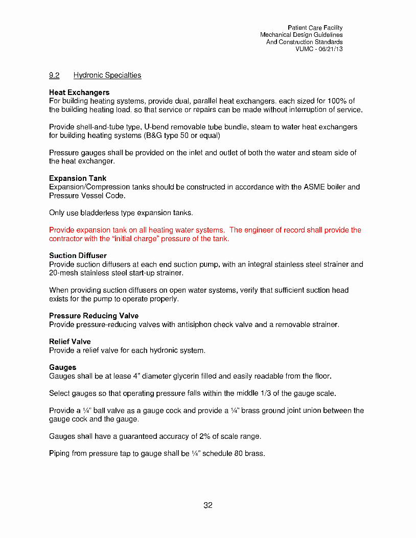
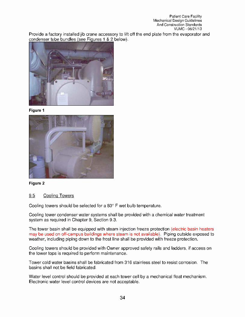
Provide a factory installed jib crane accessory to lift off the end plate from the evaporator andcondenser tube bundles see Fi ures 1 & 2 below).
Figure 1
Figure 2
9.5 Cooling Towers
Cooling towers should be selected for a 80° F wet bulb temperature.
Cooling tower condenser water systems shall be provided with a chemical water treatmentsystem as required in Chapter 9, Section 9.3.
The tower basin shall be equipped with steam injection freeze protection (electric basin heatersmay be used on off-campus buildings where steam is not available). Piping outside exposed toweather, including piping down to the frost line shall be provided with freeze protection.
Cooling towers should be provided with Owner approved safety rails and ladders, if access onthe tower tops is required to perform maintenance.
Tower cold water basins shall be fabricated from 316 stainless steel to resist corrosion. Thebasins shall not be field fabricated.
Water level control should be provided at each tower cell by a mechanical float mechanism.Electronic water level control devices are not acceptable.
34
Patient Care FacilityMechanical Design Guidelines
And Construction StandardsVUMC 06/21/13
Multiple tower cells intended to operate with a common basin should be provided withequalizing lines from each cell connecting to a common header. Each cell sump connectionshall be provided with a manual isolation valve.
Cooling tower make-up water shall be provided with a flow meter capable of recording currentand accumulative water flows. Meters shall be permitted and approved by Metro Water andSewer.
Tower basins shall be provided high and low water level basin alarms, independent of the fillcontrol device.
A hose bib shall be provided within 50 feet of all cooling tower basins.
9.6 Hot Water Heating Coils
Hot water coils should be designed for 200-psig minimum at 220° F.
Non-Face & By-pass hot water pre-heat coils should be provided with a circulating pump. Pumpshall be activated when outside air temperature drops below 45° F (adjustable).
Provide factory recommended clearance in front of coils to allow the coil to be replaced,repaired or cleaned.
Heating coils shall not be provided with more than 6 fins per inch.
35

Patient Care FacilityMechanical Design Guidelines
And Construction StandardsVUMC 06/21/13
Chapter
10Steam Producing and Management Equipment
10.1 Steam and Condensate Specialties
General RequirementsAll steam equipment handling high pressure steam, or steam upstream of PRV stations, shouldbe capable of operating at 125 psi pressure with 100 deg. F superheat (453 deg. F).
Steam condensate should be returned when possible, rather than wasting.
TrapsFloat & thermostatic (F&T) traps are preferred for the following services:
End of main (EOM) drips when pressure is no greater than 30 psiShell & Tube heat exchangersHeating CoilsUnit HeatersPlate & Frame heat exchangersAutoclavesSterilizersFlash tanksSteam jacketed equipment
Inverted bucket traps are preferred for the following services:Steam main header drainsEnd of main drips when pressure is greater than 30 psi
Provide a strainer and gate valve at the inlet of each trap.
Provide a gate valve and check valve at the discharge of each strap.
Dirt legs should be line size and extend below the return line at least 6" and should be providedwith a drain valve.
Union connections should be provided on both the inlet and discharge sides of each trap.
StrainersCleanable Y-strainers should be provided upstream of control valves and steam traps.
Steam Pressure Reducing (PRV) StationsPRVs should be iron body construction capable of operating at 250 psi, piloted type,downstream pressure sensing valve
36

Patient Care FacilityMechanical Design Guidelines
And Construction StandardsVUMC 06/21/13
Each PRV station with modulating loads should be provided with two- (2) pressure reducingvalves, 1 sized for 1/3 of the steam load and the other sized for 2/3 of the steam load.
Provide isolation valves up and down stream of PRV.
Provide pressure gauges up and down stream of the pressure reducing valve(s).
Condensate CoolersHot condensate (greater than 140° F) shall not be wasted directly to a floor drain. Condensateshould be returned to the VU power house if possible. If condensate must be wasted it shouldbe cooled in a condensate cooler prior to wasting.
10.2 Humidifiers
Humidifiers should be dry steam, direct injection type with a jacketed steam separation dryingchamber. The humidifier control valve should be positioned such that upon closure steam flowto both the humidifier and the outer jacket is prevented.
Electric or infrared humidifiers may be used in computer room A/C units or when campus steamis not available.
Locate humidifiers such that sufficient absorption distance is available prior to filters and fans.
Duct mounted humidifiers shall not be utilized without prior approval of Plant Services andSpace & Facilities Planning. Where duct mounted humidifiers are allowed, the contractor shallprovide an emergency overflow pan and duct mounted moisture sensor downstream of thehumidifier. The moisture sensor shall trigger an alarm to delta and close a dedicated twoposition steam shut-off valve.
10.3 Steam Heating Coils
Steam pre-heat coils should be vertical face & by-pass type (Wing Model IFB or equal), toreduce the risk of freezing the coil.
Avoid the use of steam reheat terminals, hot water is preferred.
Provide adequate clearance in front of coils to allow the coil to be replaced, repaired or cleaned.
10.4 Boilers
Boilers shall adhere to ASME Code for Boilers and Pressure Vessels and all state and localboiler code requirements.
Vanderbilt's Industrial Risk Insurer, Hartford Steam Boiler, shall approve boilers.
10.5 Condensate Return Pumps
Condensate return unit shall be duplex type with a cast iron receiver, mounted on a concretehousekeeping pad.
37

Patient Care FacilityMechanical Design Guidelines
And Construction StandardsVUMC 06/21/13
Alternator shall be capable of starting both pumps simultaneously if required to handle thecondensate load.
Provide a shut-off valve and a check valve in the discharge line.
38
Patient Care FacilityMechanical Design Guidelines
And Construction StandardsVUMC 06/21/13
Chapter
11Air Side Equipment
11.1 Air Handling Units
Air handling unit coils should be sized for 95°F DB, 78°F WB summer conditions and 0 °F winterconditions. In general, spaces should be maintained between 30% and 50% relative humidity.
Both variable volume and constant volume air handling system fans shall be provided withVariable Frequency Drives (VFD's) to increase energy efficiency. Inlet vanes will not beaccepted during the design or value analysis stage of the project.
Modular air handling units shall be manufactured by Trane or equal.
Air handling units should be provided with airside economizer controls to increase energysavings when possible.
Pre-heat coils should be steam face & bypass type.
All chilled water NC units provided with airside economizer controls shall be provided with apre-heat coil, sized for 100% of the supply airflow. The design engineer should considerproviding multiple control valves, sized for 1/3 and 2/3 flow, if the outside air percentage is low.
Where practical, air handling units should be provided with chilled water cooling coils, ratherthan direct expansion (DX) cooling coils.
All modules/sections of the unit will be double walled construction.
Provide 30% pre-filters and 65% cartridge filters on all units and include 90% cartridge filters onunits serving institutional areas. Refer to Chapter 11, Section 11.5 for additional filterrequirements.
Provide factory recommended clearances around units for maintenance/access to coils, motors,etc.
Coil water flow should be counter to the direction of airflow.
Provide marine observation lights in all access sections, plenums and fan sections.
Modular air handling units should be placed on a continuous base rail and a concretehousekeeping pad/curb.
39

Patient Care FacilityMechanical Design Guidelines
And Construction StandardsVUMC 06/21/13
On draw-thru type units, the height of the pad or curb and the base rail should be high enoughto properly size the condensate trap, such that the trap height exceeds the negative staticpressure by at least 1".
Ductwork connections to air handling units should be made with flexible connections.
Provide temperature gauges on the inlet and discharge side of water coils.
Coil air velocities should not exceed 500 fpm.
Drain pans shall be stainless steel 316 construction and should slope toward the drain(s).
11.2 Fan Coil Units
Fan coil units hung from the structure shall be provided with spring isolators.
Unit should be provided with 30% efficiency filters.
Heating and cooling coils should be water coils when possible.
Provide a welded galvanized drain pan under the entire unit.
Use flexible connections for ductwork connections to the unit.
Floor mounted models should have a sloped top to discourage the placement of items on top ofthe unit.
11.3 Air Terminal Units
Whenever possible, air terminal units shall be hot water coil type. Steam and electric reheatterminals are strongly discouraged.
Terminal units should be lined with foil faced glass fiber insulation.
Provide a ball valve and manual air vent the highest point on the piping connections.
Piping connections should be provided with unions and shut-off valves for replacement ofterminal unit.
Provide cleanable, line size strainers at the low point of the reheat supply run-out piping.
11.4 Fans
Supply and return fans provided on variable volume systems, should be provided with VFD's toincrease energy efficiency.
Belt drive type fans should be selected when possible.
Fans should be isolated from ductwork with flexible connections.
40

Patient Care FacilityMechanical Design Guidelines
And Construction StandardsVUMC 06/21/13
Provide proper vibration isolation for all fans, refer to Chapter 4 for additional requirements.
Provide bird screens and backdraft dampers where applicable on fans located outside or onoutside walls.
Hazardous exhaust fans should discharge at least 10'-0" feet above the roof level and bemounted at the highest roof level possible.
Hazardous exhaust fans should be located as far from air intakes as possible, but in no caseshall they be located less than 30 feet away.
All exhaust fans shall be provided with a 1/2" birdscreen and backdraft dampers
11.5 Filters
Filter racks shall be aluminum construction.
Air velocity across filters should be limited to 400-fpm maximum when possible.
Where possible, AHU pre-filters should be V-Rack housings to reduce air velocity.
All filter banks shall be provided with a manometer across the filter bank. The gauge should bemarked to indicate intended clean and dirty resistance across the filter.
Automatic roll filters shall not be used.
All filters housings on supply systems with efficiencies of 90% and greater shall be face loading,air tight with EPDM rubber or equal closed cell gaskets so that no leakage occurs when filtersare installed.
11.6 Unit Heaters
Unit heaters should be installed in all unconditioned spaces containing piping subject tofreezing.
Unit heaters should be hot water or steam type, preferably hot water.
Provide a ball valve and manual air vent on water connections.
Avoid the use of electric unit heaters if possible.
Provide unit heaters with single point electrical connections.
11.7 Electric Duct Heaters
The use of electric duct heaters should be avoided.
41

Patient Care FacilityMechanical Design Guidelines
And Construction StandardsVUMC 06/21/13
Chapter
12Sheetmetal Ductwork and Accessories
12.1 Duct Construction and Installation
The minimum standards for sheet metal fabricated and installation shall be in accordance toSMACNA "HVAC Duct Construction Standards", 1985.
All transverse duct joints/seams and duct taps, regardless of pressure classification, shall besealed with Hardcast duct sealer, consisting of impregnated woven fiber and plastic typeactivator-adhesive. Alternate water based, high pressure rated sealants may be allowed withprior written permission from Space and Facilities Planning.
Longitudinal duct joints/seams on medium and high-pressure duct systems (upstream ofterminal units) shall be sealed with Hardcast duct sealer, consisting of impregnated woven fiberand plastic type activator-adhesive.
Square duct elbows shall be provided with turning vanes, airfoil design vanes are required. UseAero/Dyne or equal.
Tees made is spiral duct shall be conical, saddle taps and straight tees are not permitted.
All medium pressure ductwork shall be pressure tested, at a pressure of 2" water gauge greaterthan the designed operating pressure or 7" wg, whichever is less, prior to insulating. Thesystem leakage shall not exceed 1% of the system air quantity.
Ductwork should be supported from the structure. Do not support duct from piping, otherductwork or sprinkler hangers.
All supply duct or any duct subject to sweating shall be insulated, refer to Chapter 5 foradditional requirements.
Ductwork should be externally insulated; the use of internal duct liner is discouraged. Whereinternal liner is necessary, the liner shall be UL listed, neoprene coated, flexible, mat facedfiberglass liner.
Refer to Chapter 14 for testing and balancing requirements of duct systems.
Kitchen range exhaust duct shall be fabricated and installed in accordance with NFPA 96.
42

Patient Care FacilityMechanical Design Guidelines
And Construction StandardsVUMC 06/21/13
122 Accessories
Supply air diffusers should all be the same face size within the same room.
Balancing dampers should be provided in the diffuser face, when diffusers are located ininaccessible ceilings.
Manual volume damper control arm should be clearly visible on the outside of duct and/orinsulation.
Butterfly type manual volume dampers shall be installed horizontally.
Round manual volume dampers ranging from 4" to 24" diameter shall be "SPIROsafe DSU"manual balancing dampers (see Figure 3 below). These shall be used in main ducts servingmultiple branches.
Figure 3
Louver faced diffusers should be used except within spaces where fume hoods are present,Titus Model TDC or equal.
Fire dampers shall be type "C", dynamically rated dampers with the damper blades out of theair-stream, with the exception of dampers behind sidewall diffusers, grilles or registers.
Access doors shall be provided where equipment service is required, including access tostationary objects in the air-stream, i.e. turning vanes.
Access doors shall be hinged type where possible. If access is not sufficient to open hingeddoors in ductwork, cam type doors are acceptable, but must be provided with a safety chain.
Do not exceed the manufacturer's recommended maximum velocities on louvers.
43

Patient Care FacilityMechanical Design Guidelines
And Construction StandardsVUMC 06/21/13
Provide removable bird screens behind louvers.
Flexible duct run-outs to diffusers or grilles shall not exceed five (5) feet.
Flexible duct shall not pass through partitions.
Flexible duct should be connected to diffusers or grilles using steel clamps or plastic strapclamps.
44

Patient Care FacilityMechanical Design Guidelines
And Construction StandardsVUMC 06/21/13
Chapter
13Controls and Facility Management System
All new buildings and renovated areas will be integrated into the existing Facility ManagementSystem known as Delta, which is located in room D-2110 of Medical Center North. Delta is set-up with multiple front-end control systems, consisting of: a Johnson Controls-Metasys system,used only for building automation; a Honeywell control system, which includes buildingautomation, fire alarm and security; a Simplex fire alarm system, and a Best Access Securitysystem.
All new buildings shall be provided with controls by Johnson Controls and connected to the JCIMetasys front end. Controls work/equipment in renovation projects shall be provided by themanufacturer with the greatest existing presence in that building.
All third party control vendors shall be under the umbrella of JCI or Honeywell so that there isonly one point of contact to the owner for controls issues.
All control devices and control systems for new buildings should be fully DDC.
Control devices for renovation areas shall match the existing controls systems of the buildingand be by the same manufacturer.
All new control devices must be addressable from Delta, such that Delta can monitor the devicestatus, read and change set-points, receive and reset alarms, start or stop fans, etc. It is notnecessary that Delta have the ability to modify set-points for off campus buildings, but theyshould receive alarms when building maintenance and/or service is the responsibility of PlantServices.
The fire alarm controls systems must be U.L. approved and approved by the buildings insuringagency.
Spare control panel capacity in new panels should be maintained at 25% or more.
Pneumatic conduit shall be no smaller than 3/4" diameter.
Use a global temperature sensor for all Medical Center projects.
Provide a "zero-loss" blow down valve for control air compressors.
Any local monitor alarms on walk-in coolers, freezers and growth chamber shall be report ageneral trouble alarm to Delta.
Poly tubing shall not be used on pneumatically controlled steam valves. Only copper shall beprovided within 18" of the actuator connection.
45

Patient Care FacilityMechanical Design Guidelines
And Construction StandardsVUMC 06/21/13
Walk-in cold rooms and low temperature freezers shall be monitored for status and a generaltrouble alarm shall be provided to Delta.
Desiccant dryers shall be used for control air systems. Refrigerated dryers are prohibited.
46
Patient Care FacilityMechanical Design Guidelines
And Construction StandardsVUMC 06/21/13
Chapter
14HVAC Systems Test and Balance
The test and balance (TAB) agency must be a certified member of the Associated Air BalanceCouncil (AABC).
The TAB contractor shall be employed by the general contractor or by Vanderbilt, rather than bythe mechanical contractor.
TAB reports should include all information required to verify that the system is installed andfunctioning as designed. This information should include, but not be limited to the following:
Design and Actual flow ratesStatic pressure readings at traverse locationsPressure drops across system componentsDischarge and suction head for each pumpActual and nameplate voltageDesign and actual entering and leaving temperaturesRated and actual amperageVerification that pumps and fans are rotating in the correct direction and operatingwithout vibrationDesign and Actual temperature readingsVerification that dampers are working properlyA list of problems and potential causes found during TAB proceduresVerification that smoke detectors have been properly located and installedInsurance that clean filters have been installed in air systemsVerification that variable frequency drives are operating properlyOpposed season balancing (reheat system). If necessary the T&B contractor shallreturn during the opposite season to complete report.
Supply, return and exhaust air outlets and traverse readings must be balanced to within plus10%, minus 5% of the design quantities. Proper pressurization should be maintained at alltimes in spaces requiring positive or negative pressurization.
OR's shall be balanced to plus 10%/ minus 0% of design air quantities.
Hydronic systems should be balanced to within plus or minus 5% of design.
For spaces requiring positive or negative pressure relationships to adjacent spaces, verify thateach space is pressurized at least 10% or 50 cfm per door.
Modify or replace belts, pulleys, dampers and impellers as required to achieve designconditions.
Prior to demolition of any ductwork, the T&B contractor shall take all readings required toidentify existing airflow deficiencies. These shall include readings at individual diffusers,registers or grilles, traverse readings at main supply, return or exhaust ducts, and fan, airhandling unit or pump readings as described above.
47
Patient Care FacilityMechanical Design Guidelines
And Construction StandardsVUMC 06/21/13
The design engineer should identify specific pre-demolition reading locations on thedemolition/existing to remain drawings and/or in the project specifications.
48
Patient Care FacilityMechanical Design Guidelines
And Construction StandardsVUMC 06/21/13
Chapter
15Specific Space Requirements and Design Criteria
15.1 General Design Criteria
The design engineer shall provide a basis of design (BOD) narrative prior to the release ofconstruction documents on all projects. This document should identify all design assumptions,as well as the design intent for the mechanical systems. Where appropriate the BOD shallinclude schematic drawings to communicate how the systems are intended to operate. Thedocument shall also include the impact of the project on the existing campus and/or buildingsystems, such as steam, chilled water, air, domestic water or any other utility that is impacted.
The HVAC systems will be based on the following minimum criteria:Summer design outdoor condition: 95 F DB and 78 F WB.Winter design temperature: 0 FIndoor design conditions:> Office Space: Summer 72 F, Winter 72 F, 50% R.H.> Laboratories: Summer 72 F, Winter 72 F, 50% R.H.> Operating Suites: Summer 65 F, Winter 65 F, 50% R.H.> Equipment Rooms: 85 F maximum, 65 F minimum.
Air change rate minimums for institutional occupancy areas shall be as defined in the 1996-97Guidelines for Design and Construction of Hospital and Health Care Facilities, ASHRAE 62-2004, Tennessee State Health Blue Book or additional requirements listed within theseguidelines. If space type is listed in multiple sources, use the most stringent requirement.
The minimum air change rate of all occupied rooms within institutional spaces shall be 2-ACH ofoutside air.
All air handling units supplying institutional spaces, as defined by NFPA 101, shall be providedwith 90% final filtration.
All walk-in coolers, freezers and growth chambers shall be pressure tested, by the mechanicalcontractor, at 2" w.g. static pressure. Leakage in excess of 1% shall be identified and correctedprior to acceptance.
15.2 General Laboratory
Laboratory fire protection systems shall conform to the requirements of NFPA 45.
Supply air diffusers should not be located where airflow patterns can have an adverse affect onfume hood safety and operation.
49
Patient Care FacilityMechanical Design Guidelines
And Construction StandardsVUMC 06/21/13
Diffusers located near fume hoods should be perforated face type diffuser, not louver type.
Services for new fume hoods should be factory installed single point connections, i.e. air, water,gas, vacuum, power, etc.
Natural gas piping should be Schedule 40 black steel.
Hood exhaust connection should be round conical type fitting.
Where 10 or more fume hoods are included in a new or renovation project, VAV fume hoodcontrols shall be provided.
Fume hood face velocity shall be monitored and/or controlled with a mass airflow thermalanemometry.
When VAV systems are provided in laboratories, a closed loop monitoring and control systemshall be provided to maintain proper room pressurization.
The fume hood manufacturer should provide data showing face velocity as a function of sashheights as 5, 10, 15, and 18-inch openings.
The nominal fume hood face velocity should be 100 fpm with the horizontal sash raised 18" fromthe working surface.
Fume hoods must pass ASHRAE-110 test as performed by an independent testing company.
In general, the minimum supply air to the laboratory should be 3.0 cfm/sq.-ft. to accommodatethe addition of future equipment.
All air should be exhausted directly to the outdoors.
Forms of energy recovery/conservation should be investigated to maximize the energyefficiency of the laboratory.
Lab should be negatively pressurized.
Do not provide fire dampers in fume hood exhaust ducts.
Verify if chemical resistance is required on the exhaust fan.
Exhaust ductwork connected to fume hoods should be constructed of corrosive resistantmaterial, i.e. stainless steel.
Refrigeration equipment provided for walk-in cold rooms and environmental growth chambersshall be located in an approved location. This equipment should not be located above thecooler unit. Equipment shall be located in one of the following locations, listed in order ofpreference: dedicated equipment room, mechanical room, rooftop, above the ceiling of anoccupied space or above the corridor ceiling.
Provide a placard on fans identifying the hood(s) location being served.
50

Patient Care FacilityMechanical Design Guidelines
And Construction StandardsVUMC 06/21/13
Internal piping within the fume hood shall be Type L (ASTM B819) hard copper tubing. Flexiblesoft copper tubing is not acceptable.
15.3 Biosafety Level 3 (BL-3) Laboratory
Refer to the design schematic in Appendix B for additional BSL-3 lab design requirements.
The architect should provide an anteroom between the lab and the corridor or adjacent space.
The lab should be designed to maintain a negative pressure between -0.05" and -0.1" w.g.
The exhaust air duct shall not be routed in a chase carrying other building system air.
All air shall be exhausted outdoors through parallel HEPA filtered exhaust fans, (one active fanand one redundant fan) served by an emergency power circuit. The exhaust air shall dischargeat least 10'-0" above the highest roof level and shall not be located within 50'-0" of outside airintakes. The exhaust fan discharge velocity shall be no less than 4,000 ft/min.
Each HEPA filter bank shall be provided with a magnahelic differential pressure gauge.
Positive seal dampers shall be provided on each fan to isolate the lead/lag fans and preventbackflow through the lag fan. The positive seal damper actuator shall be powered electricallyand shall be served from an emergency power circuit.
HEPA filter banks should be designed for bag-in/bag-out replacement and should have a 2"threaded pipe connection between the positive seal damper and the HEPA filters to allow fordecontamination and filter challenging.
Walls shall go to deck and all penetrations shall be sealed smoke and airtight.
HEPA filter supply diffusers should be provided in the lab and Ante Room.
The following alarms shall be integrated into the existing facility management system (Delta):HEPA filter pressure drop exceeding maximum and minimum setpoints.Exhaust fan status, on/offBL-3 Lab pressurization below setpoint.Lab decontamination button located outside of lab
Provide a constant volume valve on each bio-safety cabinet
Provide a variable volume supply valve that is controlled by the room pressuremonitor/controller to maintain the room pressurization at -0.075" (adj.)
Exhaust fans shall be direct drive with a VFD and shall be served by an emergency powercircuit.
Provide signage visible from 25' in all accessible directions on each fan that reads:"Caution: Biohazard Exhaust Air. Take appropriate safety precautions
51
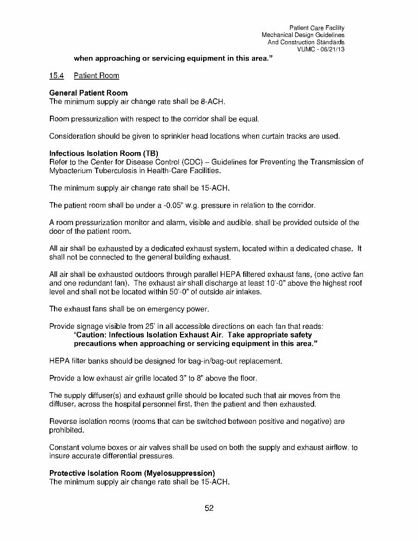
Patient Care FacilityMechanical Design Guidelines
And Construction StandardsVUMC 06/21/13
when approaching or servicing equipment in this area."
15.4 Patient Room
General Patient RoomThe minimum supply air change rate shall be 8-ACH.
Room pressurization with respect to the corridor shall be equal.
Consideration should be given to sprinkler head locations when curtain tracks are used.
Infectious Isolation Room (TB)Refer to the Center for Disease Control (CDC) Guidelines for Preventing the Transmission ofMybacterium Tuberculosis in Health-Care Facilities.
The minimum supply air change rate shall be 15-ACH.
The patient room shall be under a -0.05" w.g. pressure in relation to the corridor.
A room pressurization monitor and alarm, visible and audible, shall be provided outside of thedoor of the patient room.
All air shall be exhausted by a dedicated exhaust system, located within a dedicated chase. It
shall not be connected to the general building exhaust.
All air shall be exhausted outdoors through parallel HEPA filtered exhaust fans, (one active fanand one redundant fan). The exhaust air shall discharge at least 10'-0" above the highest rooflevel and shall not be located within 50'-0" of outside air intakes.
The exhaust fans shall be on emergency power.
Provide signage visible from 25' in all accessible directions on each fan that reads:"Caution: Infectious Isolation Exhaust Air. Take appropriate safetyprecautions when approaching or servicing equipment in this area."
HEPA filter banks should be designed for bag-in/bag-out replacement.
Provide a low exhaust air grille located 3" to 8" above the floor.
The supply diffuser(s) and exhaust grille should be located such that air moves from thediffuser, across the hospital personnel first, then the patient and then exhausted.
Reverse isolation rooms (rooms that can be switched between positive and negative) areprohibited.
Constant volume boxes or air valves shall be used on both the supply and exhaust airflow, toinsure accurate differential pressures.
Protective Isolation Room (Myelosuppression)The minimum supply air change rate shall be 15-ACH.
52

Patient Care FacilityMechanical Design Guidelines
And Construction StandardsVUMC 06/21/13
A room pressurization monitor and alarm, visible and audible, shall be provided outside of thedoor of the patient room.
Room air may be returned to the air-handling unit.
HEPA filter diffusers, or other approved HEPA filtration system, shall be provided in the patientroom and patient toilet.
The supply diffuser(s) and return grille(s) should be located such that air moves from thediffuser, across the patient first, then the hospital personnel and finally to the return/exhaustregister.
15.5 Operating Room
The minimum supply air change rate shall be 25-ACH.
Open heart and Orthopedics operating rooms shall have a minimum supply air change rate of40-ACH.
The indoor design conditions shall be 65° F and 50% relative humidity.
The air handling unit serving the O.R. shall be on emergency power.
Air shall be returned by two- (2) filtered return air grilles located in opposite corners of the room,mounted 3" 8" A.F.F.
HEPA filter laminar flow supply diffusers shall be provided with a maximum discharge velocity of25 fpm. Provided HEPA diffusers equipped with ports for filter challenging.
Terminal boxes and balancing dampers should be located above the corridor ceiling, not abovethe O.R. ceiling.
Provide a room pressure monitor/controller to modulate variable volume return air valves tomaintain 0.05" w.g. positive pressure in the OR.
15.6 Cath. Labs
The room should be positively pressurized at 0.05" w.g. static pressure.
Provide two low return air grilles, mounted 3" 8" A.F.F.
The minimum air change rate should be 20-ACH.
Final (90%) filters shall filter supply air.
The indoor design conditions should be verified with the users.
Provide a constant volume supply box or air valve to serve the Cath. Lab.
53
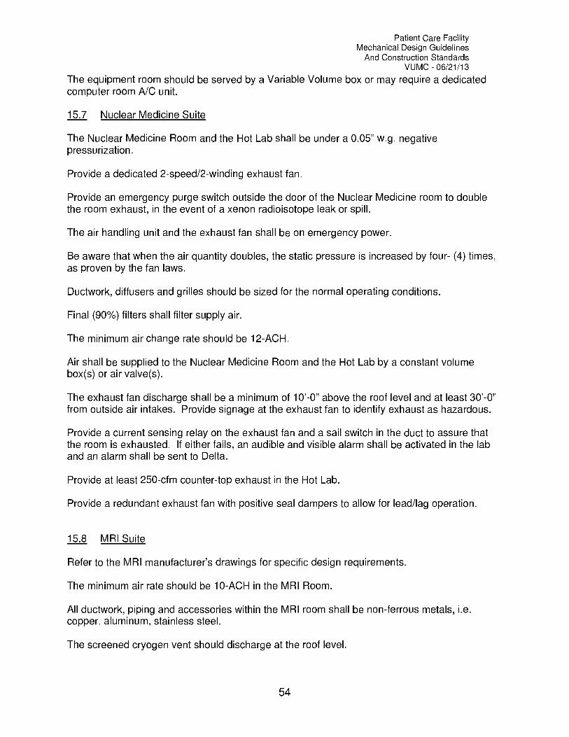
Patient Care FacilityMechanical Design Guidelines
And Construction StandardsVUMC 06/21/13
The equipment room should be served by a Variable Volume box or may require a dedicatedcomputer room A/C unit.
15.7 Nuclear Medicine Suite
The Nuclear Medicine Room and the Hot Lab shall be under a 0.05" w.g. negativepressurization.
Provide a dedicated 2-speed/2-winding exhaust fan.
Provide an emergency purge switch outside the door of the Nuclear Medicine room to doublethe room exhaust, in the event of a xenon radioisotope leak or spill.
The air handling unit and the exhaust fan shall be on emergency power.
Be aware that when the air quantity doubles, the static pressure is increased by four- (4) times,as proven by the fan laws.
Ductwork, diffusers and grilles should be sized for the normal operating conditions.
Final (90%) filters shall filter supply air.
The minimum air change rate should be 12-ACH.
Air shall be supplied to the Nuclear Medicine Room and the Hot Lab by a constant volumebox(s) or air valve(s).
The exhaust fan discharge shall be a minimum of 10'-0" above the roof level and at least 30'-0"from outside air intakes. Provide signage at the exhaust fan to identify exhaust as hazardous.
Provide a current sensing relay on the exhaust fan and a sail switch in the duct to assure thatthe room is exhausted. If either fails, an audible and visible alarm shall be activated in the laband an alarm shall be sent to Delta.
Provide at least 250-cfm counter-top exhaust in the Hot Lab.
Provide a redundant exhaust fan with positive seal dampers to allow for lead/lag operation.
15.8 MRI Suite
Refer to the MRI manufacturer's drawings for specific design requirements.
The minimum air rate should be 10-ACH in the MRI Room.
All ductwork, piping and accessories within the MRI room shall be non-ferrous metals, i.e.copper, aluminum, stainless steel.
The screened cryogen vent should discharge at the roof level.
54

Patient Care FacilityMechanical Design Guidelines
And Construction StandardsVUMC 06/21/13
Insulate the cryogen vent with at least 2" of Armaflex insulation, or another type of closed cellinsulation when it is located above occupied spaces.
A dedicated exhaust fan should exhaust the MRI room.
The computer room should be cooled by a dedicated computer room NC unit, Liebert or equal.
If a raised floor is provided in the computer room, supply through the floor and return at theceiling or top of NC unit.
Provide an oxygen sensor that will alarm at Delta if the oxygen percentage drops below 20%(adj.).
15.9 Linear Accelerator
Provide a process chiller if possible, Filtrine, Liebert or equal.
Process chiller and electric (solenoid) valve controls must be on emergency power.
Provide domestic water back up on the process water system. The control sequence shouldautomatically to domestic water and send an alarm to Delta, should the chilled water fail for anyreason.
Provide constant volume box or air valve to serve the Linear Accelerator and the EquipmentRoom.
A separate terminal unit should supply the Control Room.
15.10 Animal Care Area
Provide a minimum of 15-ACH in animal holding rooms and in O.R.'s.
All air shall be exhausted directly outside.
Provide two- (2) low filtered exhaust grilles in the animal O.R., mounted 3" 8" A.F.F.
Air in the O.R. and in animal holding rooms shall be supplied by constant volume boxes or airvalves.
Exhaust shall be at least 10'-0" above the roof level and 30'-0" from any outside air intake.
15.11 Autopsy and Morgue
Provide a minimum of 3-cfm/sq. ft. in Autopsy Rooms and in the Morgue.
All air shall be exhausted directly outside.
Air shall be supplied by constant volume boxes or air valves.
55

Patient Care FacilityMechanical Design Guidelines
And Construction StandardsVUMC 06/21/13
Counter-top exhaust may be required in the Autopsy Room.
The autopsy room suite shall be maintained under a negative pressure.
15.12 Vanderbilt Hospital and The Vanderbilt Clinic
Fire dampers are not required in 1-hour walls in the Vanderbilt Hospital or The Vanderbilt Clinic.
All smoke dampers installed in The Vanderbilt Clinic and the Vanderbilt Hospital shall be tiedinto the existing smoke control systems.
NC Smoke Control Sequence:New and existing control dampers and VAV boxes in The Vanderbilt Clinic shall performaccording to the following Smoke Control Sequence:
1. Automatic Mode:Zone is in alarm:VAV boxes used for comfort are fully closed.VAV boxes used for corridor make-up are open.Return openings in hung ceiling are 80% closed.Return openings ducted to corridor are open.
Zone is adjacent to alarmed zone:VAV boxes used for comfort are operational.VAV boxes used for corridor make-up are closed.Return openings in hung ceiling are 80% closed.Return openings ducted to corridor are closed.
Zone is not alarmed nor adjacent to an alarmed zone:VAV boxes used for comfort are operational.VAV boxes used for corridor make-up are closed.Return openings in hung ceiling are open.Return openings ducted to corridor are closed.
2. Pressurization Mode:This is the manual operation of what happens to a zone adjacent to an alarmedzone.VAV boxes used for comfort are open.VAV boxes used for corridor make-up are closed.Return openings in hung ceiling are 80% closed.Return openings ducted to corridor are closed.
3. Purge Mode:This is the manual operation of what happens to a zone in alarm.VAV boxes used for comfort are fully closed.VAV boxes used for corridor make-up are open.Return openings in hung ceiling are 80% closed.Return openings ducted to corridor are open.
56
Patient Care FacilityMechanical Design Guidelines
And Construction StandardsVUMC 06/21/13
4. Off Mode:This function shuts air flow off to the zone. The zone is not on automatic, norpressurization, nor purge. All VAV boxes and returns are closed.
5. General Notes:There should not be any exposed plastic tubing except at a final connection.In an event upon loss of air from pneumatic tube failure or leakage the followingshall occur:VAV boxes used for comfort shall Fail Open.Return dampers hung in ceiling shall Fail Open.
15.13 Pharmacy Spaces
All pharmacy spaces, including Ante Rooms, Buffer Rooms, Hazardous Buffer Rooms andBiological Safety Cabinets utilized within Buffer Rooms shall be constructed and certified inaccordance with USP 797 regulations.
57

Patient Care FacilityMechanical Design Guidelines
And Construction StandardsVUMC 06/21/13
Chapter
16Energy Efficiency and Conservation Requirements
16.1 General Design Criteria
HVAC equipment and systems shall not exceed the minimum efficiency requirementsprescribed by ASHRAE Standard 90.1-1999, Chapter 6 and 7.
HVAC equipment and systems shall not exceed the minimum requirements of the InternationalEnergy Conservation Code, 2000 version, Chapter 8.
16.2 Building Envelope Requirements
Building exterior walls shall have a maximum composite U-Value of 0.08 Btu/hr-sf.
Building roofs shall have a maximum composite U-Value of 0.06 Btu/hr-sf.
Light colored walls and roofs reflect light and heat and can reduce the amount of energyrequired to cool the building.
Revolving doors and entry vestibules reduce the amount of infiltration and save on cooling andheating expenses.
If the site allows, the building should be longer on the east to west axis and shorter on the northto south axis.
Vertical windows shall be provided with a maximum composite (glazing, edge effects and frame)summer U-Value of 0.4 Btu/hr-sf. Skylights shall have a maximum summer U-Value of 0.6Btu/hr-sf.
Building orientation should be considered when designing window size and quantity. Refer tothe tables and charts on the following pages for estimated energy impacts due to glazingexposures.
If practical, the glazing area should be greater on the North and South exposures andlimited on the East and West exposures.Windows located on the building entrance level should be provided with a high VisibleLight Transmittance (VLT).North Exposure: Windows located on the North exposure should have a high shadingcoefficient, i.e. SC=0.8, to take advantage of first cost savings.South Exposure: Windows located on the South exposure should be provided with amoderate shading coefficient, i.e. SC=0.4-0.5. As shown on the "South ElevationAnnual Energy Cost Chart", the annual building operating cost is actually less with ahigher shading coefficient. This is due to the fact that free heating is available from thesun located in the south during the heating season.
58

Patient Care FacilityMechanical Design Guidelines
And Construction StandardsVUMC 06/21/13
East Exposure: Windows located on the East exposure should be provided with lowershading coefficients, i.e. SC=0.30-0.45. This exposure has approximately the samesolar load as the west exposure, but the solar effect occurs in the morning rather thanduring the daily peak.West Exposure: Windows located on the West Exposure should be provided with verylow shading coefficients, i.e. SC=0.15-0.30.Shading from adjacent buildings and overhangs should also be considered whenselecting glass shading coefficients.
Data in the following tables and charts provides information useful in comparing first cost vs.annual building heating and cooling cost, based on various building exposures for buildingslocated on-campus. This information is based on the solar peak of a building with equal glassarea distribution on each exposure, Nashville weather data and many other assumptions. Also,some aspects relating to the annual energy cost are neglected, such as system inefficiencies,pump energy, etc. Therefore, this data should only be used for comparative purposes ratherthan a predictor of actual energy costs. This data shows how that glass U-Value has a greaterimpact on annual operating cost than it does on chiller plant first cost, while the glass ShadingCoefficient (SC) has a greater impact on chiller plant first cost than it does on annual operatingcost.
Table 1
ExposureNorthEastSouthWestNorth EastSouth EastSouth WestNorth WestAverage Peak/Sq. Ft.
ExposureNorthEastSouthWestNorth EastSouth EastSouth WestNorth WestAverage Peak/Sq. Ft.
Total Chiller Plant First Cost With Varying Shading Coefficients1000 sq. ft. Glass and a U-Value = 1.0
1.0 0.8 0.6 0.4 0.2
$4,300 $3,840 $3,380 $2,920 $2,460$10,900 $9,120 $7,340 $5,560 $3,780$8,900 $7,520 $6,140 $4,760 $3,380
$12,300 $10,240 $8,180 $6,120 $4,060$6,800 $5,840 $4,880 $3,920 $2,960
$11,000 $9,200 $7,400 $5,600 $3,800$11,800 $9,840 $7,880 $5,920 $3,960$8,400 $7,120 $5,840 $4,560 $3,280
$9,300 $7,840 $6,380 $4,920 $3,460
Total Chiller Plant First Cost With Varying Shading Coefficients1000 sq. ft. Glass and a U-Value = 0.4
1.0 0.8 0.6 0.4 0.2
$3,100 $2,640 $2,180 $1,720 $1,260$9,700 $7,920 $6,140 $4,360 $2,580$7,700 $6,320 $4,940 $3,560 $2,180
$11,100 $9,040 $6,980 $4,920 $2,860$5,600 $4,640 $3,680 $2,720 $1,760$9,800 $8,000 $6,200 $4,400 $2,600
$10,600 $8,640 $6,680 $4,720 $2,760$7,200 $5,920 $4,640 $3,360 $2,080$8,100 $6,640 $5,180 $3,720 $2,260
59
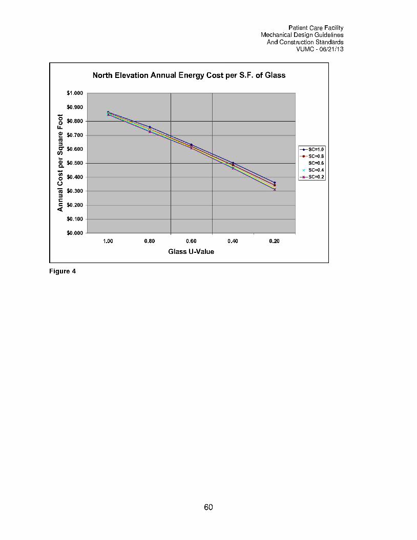
Patient Care FacilityMechanical Design Guidelines
And Construction StandardsVUMC 06/21/13
$1.000
$0.900
O $0.800u_
E $0.700cC
cs $0.600
LQ.
$0.500
O $0.400C.)
Ts: $0.300
Q$0.200
$0.100
$0.000
North Elevation Annual Energy Cost per S.F. of Glass
1.00 0.80 0.60
Glass U-Value
0.40 0.20
wSC=0.8SC=0.6
SC=0.4
* SC =0.2
Figure 4
60
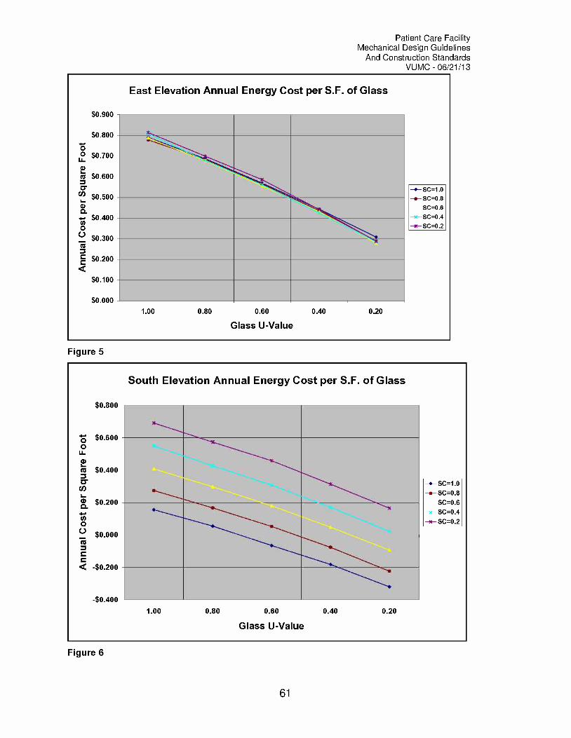
Patient Care FacilityMechanical Design Guidelines
And Construction StandardsVUMC 06/21/13
$0.900
$0.800
OO $0.700Lia)
is $0.600
Cl) $0.500a)
To. $0.400
0C.) $0.300tomO $0.200
$0.100
$0.000
East Elevation Annual Energy Cost per S.F. of Glass
1.00 0.80 0.60
Glass U-Value
0.40 0.20
o SC=1.0e SC=0.8
SC=0.6
SC=0.4
SC=0.2
Figure 5
$0.800
$0.6000
U-cD
is $0.400
cD $0.200
cn0
C.) $0.000To
< -$0.200
-$0.400
South Elevation Annual Energy Cost per S.F. of Glass
1.00 0.80 0.60
Glass U-Value
0.40 0.20
6SC=1 .0
6SC=0.8
SC=0.6
x SC=0.4x SC=0.2
Figure 6
61

Patient Care FacilityMechanical Design Guidelines
And Construction StandardsVUMC 06/21/13
$0.900
$0.800
O0 $0.700
U-a)
6c6 $0.600
$0.500a)ari; $0.400
0$0.300
rti
E $0.200
$0.100
$0.000
West Elevation Annual Energy Cost per S.F. of Glass
1.00 0.80 0.60
Glass U-Value
0.40 0.20
6- SC=1 .0
6- SC=0.8SC=0.6
SC=0.4
-x- SC=0.2
Figure 7
16.3 Minimum Motor Efficiencies
Polyphase motors furnished as part of mechanical equipment shall be premium efficient motorswith an efficiency service factor of 1.15 (minimum) and class F insulation. 480V, 60Hz typemotors must meet NEMA MGI part 31.40.4.2. Premium efficient motors must have the followingfull load minimum efficiencies:
34 HP 80.0% with a maximum slip = 5%1 HP 84.0% with a maximum slip = 4%1 1/2 2 HP 86.5% with a maximum slip = 3%3 5 HP 89.5% with a maximum slip = 2.5%7 1/2 10 HP 90.7% with a maximum slip = 2.8%15 HP 92.0% with a maximum slip = 2.5%20 25 HP 93.0% with a maximum slip = 2.5%30 HP 94.0% with a maximum slip = 1.9%40 HP 94.0% with a maximum slip = 1.7%50 HP 94.0% with a maximum slip = 1.4%60 HP and greater 95.0% with a maximum slip = 1.4%
Refer to the Vanderbilt University Medical Center Electrical Standards for additional motorrequirements.
62
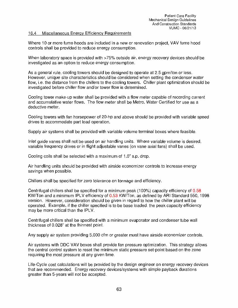
Patient Care FacilityMechanical Design Guidelines
And Construction StandardsVUMC 06/21/13
16.4 Miscellaneous Energy Efficiency Requirements
Where 10 or more fume hoods are included in a new or renovation project, VAV fume hoodcontrols shall be provided to reduce energy consumption.
When laboratory space is provided with >75% outside air, energy recovery devices should beinvestigated as an option to reduce energy consumption.
As a general rule, cooling towers should be designed to operate at 2.5 gpm/ton or less.However, unique site characteristics should be considered when setting the condenser waterflow, i.e. the distance from the chillers to the cooling towers. Chiller plant optimization should beinvestigated before chiller flow and/or tower flow is determined.
Cooling tower make-up water shall be provided with a flow meter capable of recording currentand accumulative water flows. The flow meter shall be Metro. Water Certified for use as adeductive meter.
Cooling towers with fan horsepower of 20-hp and above should be provided with variable speeddrives to accommodate part load operation.
Supply air systems shall be provided with variable volume terminal boxes where feasible.
Inlet guide vanes shall not be used on air handling units. Where variable volume is desired,variable frequency drives or in flight adjustable vanes (on vane axial fans) shall be used.
Cooling coils shall be selected with a maximum of 1.0" s.p. drop.
Air handling units should be provided with airside economizer controls to increase energysavings when possible.
Chillers shall be specified for zero tolerance on tonnage and efficiency.
Centrifugal chillers shall be specified for a minimum peak (100%) capacity efficiency of 0.58KW/Ton and a minimum IPLV efficiency of 0.53 KW/Ton, as defined by ARI Standard 550, 1998version. However, consideration should be given in regard to how the chiller plant will beoperated. Example, if the chiller specified is to be base loaded, the peak capacity efficiencymay be more critical than the IPLV.
Centrifugal chillers shall be specified with a minimum evaporator and condenser tube wallthickness of 0.028" at the thinnest point.
Any supply air system providing 5,000 cfm or greater must have airside economizer controls.
Air systems with DDC VAV boxes shall provide fan pressure optimization. This strategy allowsthe central control system to reset the minimum static pressure set-point based on the zonerequiring the most pressure at any given time.
Life-Cycle cost calculations will be provided by the design engineer on energy recovery devicesthat are recommended. Energy recovery devices/systems with simple payback durationsgreater than 5-years will not be accepted.
63
Patient Care FacilityMechanical Design Guidelines
And Construction StandardsVUMC 06/21/13
Condensate from air handling units providing 75% outside air or greater, should be capturedand utilized for cooling tower make-up whenever possible.
16.5 Commissioning
Commissioning services as defined by ASHRAE Guideline 1-1996 will be required on allpertinent Medical Center projects. Table 2 below defines three (3) Tiers of commissioningservice requirements. Every project with equipment and/or systems identified in one of thesethree Tiers shall require a commissioning plan as characterized by Table 2. In addition tocommissioning requirements of Tiers 1, 2 and 3, equipment and/or systems identified asAlternates may be included in the commissioning plan if the owner chooses.
64

Table 2
Patient Care FacilityMechanical Design Guidelines
And Construction StandardsVUMC 06/21/13
Vanderbilt Medical Center Commissioning Requirements
COMMISSIONING LEVELSTier - 1: Projects < 10,000 sq. ft. and < $500,000 M,P&E Construction CostTier - 2: Projects Greater Than 10,000 sq. ft. and/or $500,000 M,P&E Construction CostTier - 3: Projects Greater Than 200,000 sq. ft. and/or $10,000,000 M,P&E Construction CostAlternates: Determined independently on a per project basis
Scope of ServicesCommissioning Level
Tier1
Tier2
Tier3 Alternates
Process Management
Introduce independent commissioning agent during the design phase
Introduce independent commissioning agent during the constructionphase
Owner provide and direct commissioning plan
Design engineer provide specifications for commissioning services
Insure O&M manuals and training is provided per documentrequirements
Insure System Training is provided per document requirements
Energy cy SysteFans with motors greater than 5-hp.Pumps with motors greater than 5-hp.Air handling units with capacities of 5-tons or greater (Including allinterconnected equipment, i.e. interlocked fans or recirc. pumpsregardless of motor HP).
Adjustable speed drives greater than 5-hp.Air distribution systems including 25% of all DDC boxesHydronic distribution systemsAll electric heating systemsDomestic hot water systemsControls system from device to front-end, associated withcommissioned equipmentChillers (Including emergency shut-down controls)In addition to standard performance commissioning, chillerscommissioning shall include vibration testing and a compressor oilanalysis. The oil analysis shall provide a measurement of metalwear, moisture, acidity and viscosity. These results shall becompared to the factory tests and will serve as the "as installed" baseline.
Cooling Towers
X
X
X
X
X X
X X
X X XX X X
X X X
X X XX XX X
X X XX X
X X
X X XX X X
65
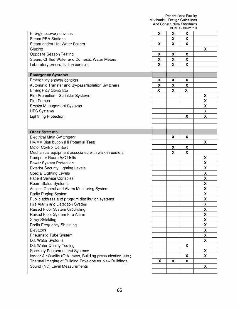
Energy recovery devicesSteam PRV StationsSteam and/or Hot Water BoilersGlazingOpposite Season TestingSteam, Chilled Water and Domestic Water MetersLaboratory pressurization controls
Emergency SystemsEmergency shower controlsAutomatic Transfer and By- pass /Isolation SwitchersEmergency GeneratorFire Protection Sprinkler SystemsFire PumpsSmoke Management SystemsUPS SystemsLightning Protection
Other SystemsElectrical Main SwitchgearHV/MV Distribution (Hi Potential Test)Motor Control CentersMechanical equipment associated with walk-in coolersComputer Room A/C UnitsPower System ProtectionExterior Security Lighting LevelsSpecial Lighting LevelsPatient Service ConsolesRoom Status SystemsAccess Control and Alarm Monitoring SystemRadio Paging SystemPublic address and program distribution systemsFire Alarm and Detection SystemRaised Floor System GroundingRaised Floor System Fire AlarmX-ray ShieldingRadio Frequency ShieldingElevatorsPneumatic Tube SystemD.I. Water SystemsD.I. Water Quality TestingSpecialty Equipment and SystemsIndoor Air Quality (0.A. rates, Building pressurization, etc.)Thermal Imaging of Building Envelope for New BuildingsSound (NC) Level Measurements
66
Patient Care FacilityMechanical Design Guidelines
And Construction StandardsVUMC 06/21/13
x X XX X
X X XX
X X XX X XX X X
X X XX X XX X X
XXXX
X X
X XX
X XX X
XXXXXXXXXXXXXXXXX
XX
X XX X X
X

Patient Care FacilityMechanical Design Guidelines
And Construction StandardsVUMC 06/21/13
Chapter
17Mechanical and Plumbing Details
The following standard details shall be utilized on all Vanderbilt University Medical Centerprojects where applicable. It is acceptable for design engineers to use their own details andown numbering system, as long as the equipment and components are utilized in the sameorder and fashion as identified in this document. Refer to Appendix A for Mechanical andPlumbing Details.
17.1 Mechanical Details
The following is an index of mechanical details that have been adopted by Vanderbilt UniversityMedical Center:
MO1 Chilled Water Piping at Multiple CoilsM02 Chilled Water Piping at Single CoilM03 Chilled and Condenser Water Piping at Refrigeration MachineM04 Piping at Plain Steel Expansion TankM05 Piping at Terminal Reheat BoxM06 Hot Water Piping at ConvertorM07 Condensate CoolerM08 Two Stage Pressure Reducing StationM09 Piping at Bladder Expansion TankM10 Make-Up Water to Cooling TowerM11 Cooling Tower Chemical Feed PumpM12 Steam Relief ValveM13 End Suction Water PumpM14 In-Line Circulating PumpM15 Double Suction Water Pump with Y-StrainerM16 Double Suction Water Pump with Suction DiffuserM17 A/C Unit Mounted HumidifierM18 Steam Piping at ConvertorM19 Automatic Steam Control Valve AssemblyM20 Steam Piping at Heating CoilM21 Steam Piping at Horizontal Multiple Heating CoilsM22 Steam Piping at Heating CoilM23 Roof Mounted Belted Vent Set Exhaust FanM24 Ductwork Connection to Supply DiffuserM25 Dryer Lint Trap with ScreenM26 Emergency Generator Muffler Exhaust PipeM27 Piping at Above Floor Condensate Pump
67

Patient Care FacilityMechanical Design Guidelines
And Construction StandardsVUMC 06/21/13
17.2 Plumbing Details
The following is an index of plumbing details that have been adopted by Vanderbilt UniversityMedical Center:
P01 Steam Piping at Instantaneous Water HeaterP02 Barrier Free Emergency ShowerP03 Medical Gas ManifoldPO4 Deionized Water SystemP05 Trap Primer DistributionP06 Reduced Pressure Backflow PreventerP07 Duplex Sewage Lift StationP08 Duplex Sump PumpP09 Water Meter Detail
68

Patient Care FacilityMechanical Design Guidelines
And Construction StandardsVUMC 06/21/13
Chapter
18O&M Closeout Documentation
The purpose of this document is to define the required structure for the preparation of Operatingand Maintenance documentation for Vanderbilt University Medical Center projects. The date ofsubstantial completion of a project shall not be accepted by Vanderbilt prior to the acceptanceand approval of all required O&M documentation.
Closeout documents must be reviewed and accepted for compliance by the Engineer of Recordand/or the project commissioning authority prior to final submission to Vanderbilt. Thesedocuments must be stamped for approval by the reviewing authority.
The O&M documentation package shall include the following:I. O&M Documentation Table of Contents (Include in all Volumes)II. Emergency Response Information (Include in all Volumes)Ill. Operating Manual(s)IV. Maintenance Manual(s) Group Sections III V per CSI
Specification DivisionsV. Test ReportsVI. Construction Documents
I. O&M Documentation Table of ContentsAt the front of each volume provide a master table of contents which includes a directory ofall volumes as well as the contents of that particular volume.
II. Emergency Response InformationEmergency information shall be well organized to allow for quick reference, thus minimizingthe risk of life, property and disruption to the building occupants. Provide a table of contentsidentifying all types of emergencies for which safety information is available.
Example: Emergency Information Table of Contents
Type of Emergency Page No.Fire ##Security ##Floods ##Gas ##Power Failure ##Water Outages ##Elevator ##Heating ##Cooling ##Refrigerant release ##
69
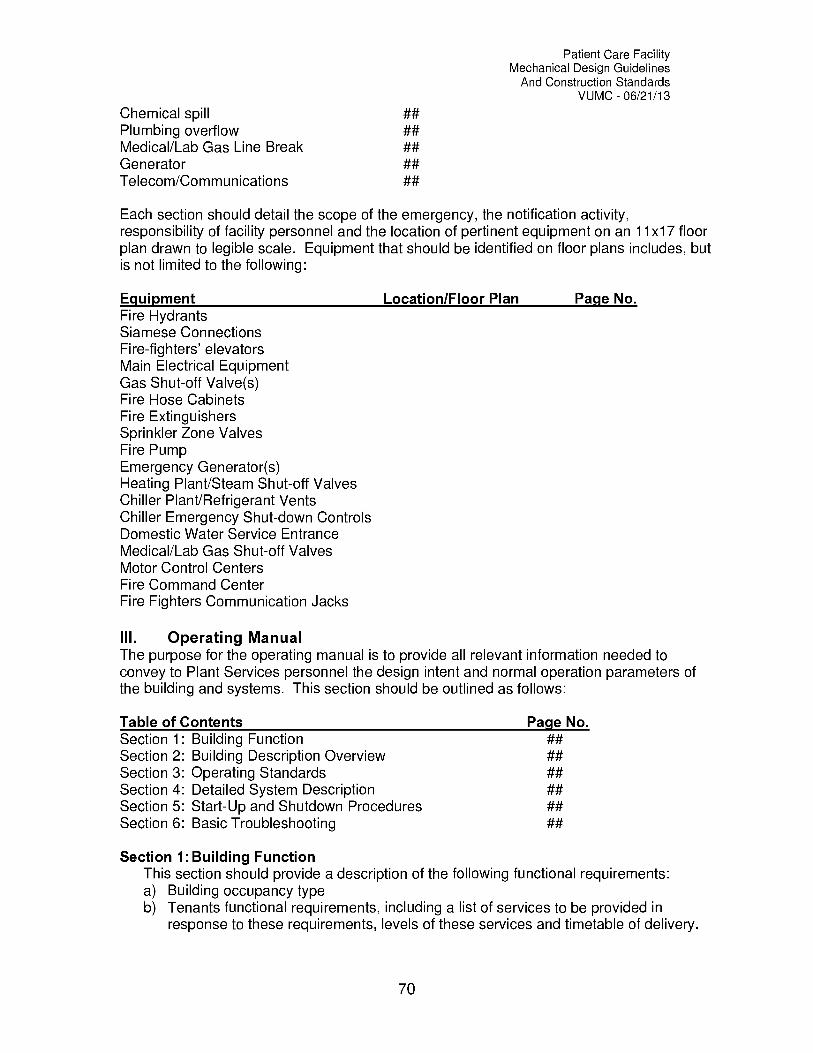
Patient Care FacilityMechanical Design Guidelines
And Construction StandardsVUMC 06/21/13
Chemical spill ##Plumbing overflow ##Medical/Lab Gas Line Break ##Generator ##Telecom/Communications ##
Each section should detail the scope of the emergency, the notification activity,responsibility of facility personnel and the location of pertinent equipment on an 11x17 floorplan drawn to legible scale. Equipment that should be identified on floor plans includes, butis not limited to the following:
Equipment Location/Floor Plan Page No.Fire HydrantsSiamese ConnectionsFire-fighters' elevatorsMain Electrical EquipmentGas Shut-off Valve(s)Fire Hose CabinetsFire ExtinguishersSprinkler Zone ValvesFire PumpEmergency Generator(s)Heating Plant/Steam Shut-off ValvesChiller Plant/Refrigerant VentsChiller Emergency Shut-down ControlsDomestic Water Service EntranceMedical/Lab Gas Shut-off ValvesMotor Control CentersFire Command CenterFire Fighters Communication Jacks
III. Operating ManualThe purpose for the operating manual is to provide all relevant information needed toconvey to Plant Services personnel the design intent and normal operation parameters ofthe building and systems. This section should be outlined as follows:
Table of Contents Page No.Section 1: Building Function ##Section 2: Building Description Overview ##Section 3: Operating Standards ##Section 4: Detailed System Description ##Section 5: Start-Up and Shutdown Procedures ##Section 6: Basic Troubleshooting ##
Section 1:Building FunctionThis section should provide a description of the following functional requirements:a) Building occupancy typeb) Tenants functional requirements, including a list of services to be provided in
response to these requirements, levels of these services and timetable of delivery.
70

Patient Care FacilityMechanical Design Guidelines
And Construction StandardsVUMC 06/21/13
c) Municipal requirements, including fire department's response, water use policy, etc.d) Utility information, including names, addresses, phone numbers and e-mail
addresses of utility companies for normal and emergency purposes.
Section 2: Building Description OverviewThis section provides a brief description of layouts of the building's floor areas. It should
also provide an overview of the building systems using a short text description and simplifiedsingle-line schematic drawings. This section should show utility shut-off locations on smallscale 11x17 floor plans with a description of what areas of the building are supplied by theutility and by each shut-off device.
Section 3: Operating StandardsThis section should provide the standards of performance for the building and operating
procedures for each system. The operator must understand how to operate each system toachieve the desired standard of performance. These standards include, but are not limitedto the following:
A. Space temperature set-points and acceptable range(s)B. Space humidity set-points and acceptable range(s)C. Ventilation ratesD. Chilled-water supply temperatureE. Hot water temperature scheduleF. Domestic water temperatureG. Steam pressureH. Manual transfer from normal to emergency powerI. Manual parallel and synchronization of generators
Section 4: Detailed System DescriptionThis section should begin with a list of all systems similar to the list in Section 2, followed
by a detailed description of each system listed.This should include a narrative describing the basis of design for each system. The
description should identify the areas of the building that the systems serve, the locations ofperformance checkpoints (i.e. static pressure sensors), the expected performance readingsat the design load conditions and, where applicable, at part-load conditions. The systems'operation during the day, night, and weekend, as well as seasonal start-up and turndown,safety devices and their function, control devices and their function, etc.
The function of the controls for individual systems should be described alongside thedescription of the system function and an overview of the entire control system should beprovided.
The systems included in this section include, but are not limited to the following:A. Fire and SafetyB. HeatingC. CoolingD. Air DistributionE. LightingF. Chemical water treatmentG. ControlsH. RefrigerationI. PlumbingJ. Medical Gas
71
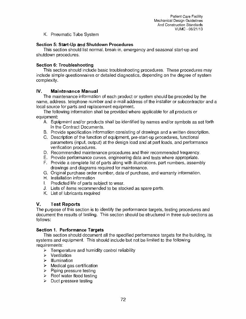
Patient Care FacilityMechanical Design Guidelines
And Construction StandardsVUMC 06/21/13
K. Pneumatic Tube System
Section 5: Start-Up and Shutdown ProceduresThis section should list normal, break-in, emergency and seasonal start-up and
shutdown procedures.
Section 6: TroubleshootingThis section should include basic troubleshooting procedures. These procedures may
include simple questionnaires or detailed diagnostics, depending on the degree of systemcomplexity.
IV. Maintenance ManualThe maintenance information of each product or system should be preceded by the
name, address, telephone number and e-mail address of the installer or subcontractor and alocal source for parts and replacement equipment.
The following information shall be provided where applicable for all products orequipment:
A. Equipment and/or products shall be identified by names and/or symbols as set forthin the Contract Documents.
B. Provide specification information consisting of drawings and a written description.C. Description of the function of equipment, pre-start-up procedures, functional
parameters (input, output) at the design load and at part loads, and performanceverification procedures.
D. Recommended maintenance procedures and their recommended frequency.E. Provide performance curves, engineering data and tests where appropriate.F. Provide a complete list of parts along with illustrations, part numbers, assembly
drawings and diagrams required for maintenance.G. Original purchase order number, date of purchase, and warranty information.H. Installation informationI. Predicted life of parts subject to wear.J. Lists of items recommended to be stocked as spare parts.K. List of lubricants required
V. Test ReportsThe purpose of this section is to identify the performance targets, testing procedures anddocument the results of testing. This section should be structured in three sub-sections asfollows:
Section 1. Performance TargetsThis section should document all the specified performance targets for the building, its
systems and equipment. This should include but not be limited to the followingrequirements:
> Temperature and humidity control reliability> Ventilation> Illumination> Medical gas certification> Piping pressure testing> Roof water flood testing> Duct pressure testing
72

Patient Care FacilityMechanical Design Guidelines
And Construction StandardsVUMC 06/21/13
> Chiller efficiency and capacity testing> Vibration isolation testing> Motor Control Centers> Switchgear> Emergency Generators> Radiation Shielding> Fire Pump Flow Testing
Section 2. Testing ProceduresThis section should contain testing procedures for all tests that were performed. This
information should be located in the specifications, from which it should be copied andshown here for convenience.
Section 3. Test ResultsThis part of the document should, for each system and/or piece of equipment as
applicable, catalog in chronological order the results of the tests performed in the factoryand on site. It should also allow for inclusion of additional test results performed throughoutthe service life of the facility.
VI. Construction DocumentsThis segment consists of six (6) elements containing the following documents:
Section 1: Record DrawingsSection 2: Final specifications with all addendaSection 3: Approved product data and shop drawingsSection 4: Warranty CertificatesSection 5: Inspection CertificatesSection 6: Final Commissioning Report
73

Appendix
A
Patient Care FacilityMechanical Design Guidelines
And Construction StandardsVUMC 06/21/13
Mechanical and Plumbing Details
74

PROVIDE MANUAL CHSAIR VENT ATHIGH POINT OFRETURN LINE.
CONTROL VALVE(2-WAY OR3-WAY). SEECONTROLDRAWINGS.
BALANCING VALVE(TYPICAL)
CHRUNION AND REMOVEABLE SECTIONS TO ALLOWTEMPORARY FLUSHING CONNECTIONS AT VALVES.
BUTTERFLY VALVE (TYPICAL). BALLVALVES ON SMALLER SIZES. (SEE SPECS. )
THERMOMETER (TYPICAL)
GAGE& COCK
CONN. SIZE OR MIN. 1/2 BALLVALVE AIR VENT (TYPICAL)
STAINLESSPETE'S TEST STEELPLUG ( TYP. ) COIL
FRAME
COOLINGCOIL
GAGE COCK(TYP. )
LOCATE VENTVALVES OUTSIDEUNIT HOUSING
COMPANIONFLANGES(TYPICAL)
LINE SIZEDIRT LEG(TYPICAL)
COOLINGCOIL
FULL CONN, SIZEON COOLING COIL.(TYPICAL)
3/4 HOSE ENDGATE VALVE(TYPICAL)
CONNECTION SIZE 1/2 ' MIN. DRAINVALVE. PIPE TO FLOOR DRAIN.LOCATE VALVE OUTSIDE UNIT HOUSING
N 0 T E
1. WATER SHALL ENTER COIL ONAIR LEAVING SIDE OFFSET PIPINGAS SHOWN TO ALLOW FOR COILPULL WITHOUT DISMANTLINGVERTICAL RISERS.
CHILLED WATER PIPI\GAT vULTIPLE COOLING COILS v-1

PROVIDE MANUAL AIR VENT ATHIGH POINT OF RETURN LINE.
BALANCINGVALVE (TYP)
CHS1
CHR BUTTERFLY VALVE (TYPICAL).j_ BALL VALVES ON SMALLER
SIZES. (SEE SPECS.)
UNION & REMOVEABLE SECTIONS TO ALLOWTEMPORARY FLUSHING CONNECTIONS AT VALVES.
THERMOMETER (TYPICAL)
GAUGE & GAUGE COCK
OFFSET PIPING AS SHOWN TOALLOW COIL PULL WITHOUTDISMANTLING VERTICAL RISERS.
1 1/2 ' BALLVALVE AIRVENT. LOCATE VALVEOUTSIDE UNITHOUSING.
CONTROL VALVE(2-WAY OR3-WAY). SEECONTROLDRAWINGS.
WATER SHALL
COMPANIONFLANGES(TYPICAL)
ENTER COILON AIR LEAVINGSIDE.
LINE SIZEDIRT LEG
/L, 3/4 ' HOSEGATE VALVES
STAINLESS STEELFRAME
CONNECTION SIZE 1/2 ' MIN. DRAINVALVE. PIPE TO FLOOR DRAIN.LOCATE VALVE OUTSIDE UNIT HOUSING.
USE LARGER OF SIZE SHOWN ON DRAWINGOR COIL CONN. SIZE (TYPICAL)
CHILLED WATER PIPI\GAT SI\GLE COOLI\G COIL V 2

CONDENSER OR CHILLEDWATER PIPE
BUTTERFLY VALVE. MOUNTAS HIGH AS POSSIBLE TOMAXIMIZE THE SIZE OF THEBREAKOUT SPOOL ON SUPPLYAND RETURN. (LOCATE NO LESSTHAN 12" ABOVE CHILLER)
PROVIDE SPOOL PIECEBETWEEN VALVES.
PROVIDE THERMOMETERAND PRESSURE GAUGE ONSUPPLY AND RETURN LINES.THERMOMETER SHALL BE 12" CASEINDUSTRIAL, ADJUSTABLE ANGLE,SCALE RANGE 0 TO 100 r"
TYPICAL-ONETHUS FORCHILLER ANDCONDENSERSHELLS
C>"
M
FLUSHING LOOPSEE NOTE BELOW
AUTOMATIC CONTROL VALVEWHERE CALLED FOR ONCONTROL DRAWINGS. SUPPLIEDBY CONTROL CONTRACTOR.
191w w 61_,V)IPE FROM THIS POINT SHALLBE REMOVABLE WITHOUT DRAININGPIPE AHEAD OF BUTTERFLY VALVEON SUPPLY AND RETURN LINES.
CONR SIZE,3/4
llorzAIR VENT
GLYCERN FILLED 4 1/2 " SIZEGAGE, 1/2% ACCURACY.MOUNT GAGES ON SUPPLY& RETURN LINES AT SAMEELEVATION.
REFRIGERATIONMACHINE
4' CONCRETEBASE
E
E
zFLANGEDCONNECTION
GAGE COCK
PETE'S PLUG
FLOW SWITCH
LONG RADIUS ELL
OFFSET PIPING TOALLOW FOR TUBE PULL.MAKE DISCONNECTABLE
ALL PIPES SHALL HAVEFLOOR SUPPORTS. ALLOWNO PIPING WEIGHT TOREST ON CHILLER.
ON ROTARY SCREW CHILLERSPROVIDE FLANGED FLEXIBLENEOPRENE ISOLATION CONNECTERSHERE.
CONR SIZE, 3/4 "MIN. DRAIN VALVE W/THREADED HOSE CONR
NOTES:TEMPORARY FLUSHING LOOP, CONNECTION ONE SIZESMALLER THAN LINE SIZE OR 6" (WHICHEVER IS SMALLER),REMOVE AND CAP WHEN SYSTEM IS PROVEN CLEAN FROM FLUSHING.
ALL GUAGES TO BE OF SAME PRESSURE RANGE.
CHILLED A\D CO\DE\SER WATER PIPI\GAT REFRIGERATIO\ VArk-IT\F ( FOUR PER MACHINE)
V 3

NOTEVENT TUBE SHALL EXTEND INTOTANK 2/3 OF TANK DIAMETER.
CITY WATER MAKE -UP. SEE SCHEDULEFOR SIZE. PROVIDE REDUCED PRESSUREBACKFLOW PREVENTER FOR THIS LINE.
/-GAUGE & GAUGECOCK W/ SNUBBER
GAUGEGLASSLASS
(TYPICAL
EXPANSIONTANK
(LOCATED AT TOP OF SYSTEM)
6'r*1DRAIN
LINESIZE
SYSTEM TANKFITTING W/AIRVENT, SEE NOTE
GLOBEVALVE
LINE SIZE QUICKFILL/BYPASS
P. R. V. SEESCHEDULEFOR SETTING
LINE SIZE CONN. TO SYSTEMSEE SYSTEM SCHEMATIC FORTIE-IN AT PUMP SUCTION
BALL VALVE(TYPICAL)
CONN.SIZE
TO FLOORDRAIN
TRI-LEVERRELIEF VALVESEE SCHEDULEFOR SETTING
TANK SCHEDULE
SYSTEM TANK SIZE(GALLONS)
P. R. V.
INLET PRESS.(P. S. I. )
P. R. V.
OUTLET PRESS.(P. S. I, )
(P. S. I. )INITIALCHARGE
RELIEF VALVE
SETTING (PSI)
PIPING'LINE SIZE'
PIPI\G AT PLAI\STEEL EXPA \SILI TA\K
V 4

3/8 " BALLVALVEAIR VENT
PETE'SPLUG
UNION(TYPICAL)
BALL VALVE(TYPICAL)
NOTES:
2-WAY CONTROL VALVE(3-WAY CONTROL VALVEWHERE SHOWN ON PLANS).PROVIDED BY CONTROLCONTRACTOR
REFER TO BOXSCHEDULE FORRUNOUT PIPESIZES.
BALL VALVE(TYPICAL)
ilk?
B & G CIRCUITCONTROL
L PIPING SAME FOR HEATING COIL IN HOT WATER REHEATTERMINAL BOXES AND FOR DUCT MOUNTED HOT WATERHEATING COILS.
V:5
PIPI\G AT TERVI \AL REHEAT (BOX OR COIL)

THERMOMETER(TYPICAL)
HOT WATER RETURNFROM SYSTEM
(1
GAUGE COCK
\(TYPICAL)
CONTROL VALVE(PROVIDED BY)CONTROL CONTRACTOR)
(SEE STEAM PIPINGAT CONVERTORDETAIL. )
ARRANGE PIPING AS SHOWNTO ALLOW FOR TUBE BUNDLEREMOVAL. LOCATE AND MOUNTCONVERTOR TO PROVIDESUFFICIENT CLEAR SPACETO ALLOW TUBE REMOVAL.
CONVERTOR
ISOLATION VALVESCONTROL VALVE(PROVIDED BY)CONTROL CONTRACTOR)
FLANGED CONNECTION (TYPICAL)-'
RELIEF VALVE SIZED EQUALTO CONVERTOR CAPACITY
HOT WATER SUPPLYTO SYSTEM
TYPICAL BUTTERFLY VALVE(BALL VALVE SMALLER PIPE).SEE SPECIFICATIONS,
NOTE:
VUMC REQUIRES TWOCONVERTORS IN PARALLELFOR HEATING SYSTEMS.
TO EXPANSIONTANK. (SEEDETAIL. )
AIR SEPARATOR
CONN, SIZE DRAINVALVE. PIPE TOFLOOR DRAIN.
3/4 ' BALL VALVEMANUAL AIR VENT
TO/FROM PUMP (TYPICAL).SEE PUMP DETAIL.
HOT WATER PIPI\G AT CO\VERTOR V 6
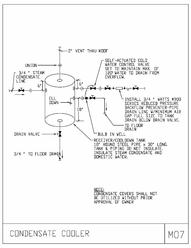
UNION1-7-2'
VENT THRU ROOF
SELF-ACTUATED COLDWATER CONTROL VALVESET TO MAINTAIN MAX. OF
3/4 ' STEAM 12MWATER TO DRAIN FROMCONDENSATE OVERFLOW,LINE
DRAIN VALVE
3/4 ' TO FLOOR DR
INSTALL 3/4 ' WATTS #900SERIES REDUCED PRESSUREBACKFLOW PREVENTER-PIPEDRAIN LINE W/MINIMUM AIRGAP FULL SIZE TO TANKDRAIN BELOW DRAIN VALVE.
TO FLOORDRAIN
BULB IN WELL
RECEIVER/COOLDOWN TANK10' ROUND STEEL PIPE x 30' LONG,TANK & PIPING DO NOT INSULATE.INSULATE STEAM CONDENSATE ANDDOMESTIC WATER.
NOTE:CONDENSATE COVERS SHALL NOTBE UTILIZED WITHOUT PRIORAPPROVAL OF OWNER
CO\DE\SATE COOLER vN_I 7

HIGH PRESSURE
STEAM SUPPLY
LOW PRESSURE
STEAM SUPPLY Q
GAUGE AND
COCK
TYPICAL STRAINER &
BLOW DOWN VALVE,
SEE NOTE.
BYPASS LINE SIZE TO BE
ONE SIZE SMALLER THAN
\LARGER P. R. V.
SIZE
LINE SIZE
DIRT LEG
FROM
FLASH
I-
TANK
BUCKET
TRAP
IloT
4
GLOBE VALVE
-\
SIZE 'C/
DRIP PAN ELL
LINE SIZE VENT
UP THRU ROOF
TO ATMOSPHERE
(NOTE 2)
RELIEF
VALVE
MJcs,
MEDIUM PRESSURE
STEAM SUPPLY
PIPE TO
NEAREST
FLOOR DRAIN
SIZE 'D'
GAUGE AND
COCK
11-14h4fil-1
SIZE 'B'
1I
I 1
ii--44.4-1
\-SIZE 'A'
-IV PRESSURE
PRESSURE
REDUCING
REDUCING
VALVE #1
VALVE #2
4,,e-RELIEF VALVE
TITO HIGH PRESS.
FLASH TANK.
SEE DETAIL.
U
GAUGE AND
COCK
PIPE TO
NEAREST
FLOOR DRAIN
3/4 '
F.
TRAP
T 1
I
UNOTES1
SIZE 'D'
LOCK AND
SHIELD VALVE
(TYP. )
10'-0' MIN.
LENGTH (TYP.)
SIZE'F=7
GLOBE VALVE (TYP.)
TO FLOOR DRAIN
19sci_
SIZE 'E'
SIZE 'F'
PRESSURE
REDUCING
VALVE #2
1.
INSTALL'Y' STRAINERS WITH BASKETS
HORIZONTALLY, POINTING OUT NOT DOWN.
2.
VENT LINES MAY BE GANGED
IF VENT LINE IS INCREASED
ONE LINE SIZE.
\N_
3/4 '
TO COND.
PUMP
1.4.1
II
SIZE 'C'
PRESSURE
REDUCING
VALVE #1
TO LOW PRESS.
FLASH TANK.
SEE DETAIL.
IBS
07-SIZE
'A'
I
BUCKET
TRAP
LINE SIZE VENT
THRU ROOF (NOTE 2)
DRIP PAN ELL
BYPASS LINE SIZE
TO BE ONE SIZE
SMALLER THAN
LARGER P. R. V.
SIZE
LINE SIZE
DIRT LEG
U
PRESSURE
REDUCING
VALVE
SCHEDULE
STA.
NO.
MFR.
&MODEL
P. R. V.
NO.
VALVEP,
SIZE
S. I
IN
LBS. /
HR.
SIZESIZESIZE
' A"B"
C'
NO.
OF
VALVESP. S. I,SIZESIZESIZE
OUT
D'
'-
' F
' F '
RELIEF
VALVE
SETTINGSERVICE
1212
TWO STAGE PRESSURE REDUCING STATION
M08

'LINE SIZE'CITY WATER MAKE -UP. PROVIDE REDUCEDPRESSURE BACKFLOW PREVENTER FOR THISLINE, SEE PLUMBING DRAWING FOR CON-TINUATION
GAUGE & GAUGECOCK W/SNUBBER
GLOBEVALVE
Q LINE SIZE QUICKFILL/BYPASS
BALL VALVE
UNION CAL)-'
CHECK VALVE
11---INI----10-111V1-1"05
N 0 T E :
INSTALL AUTO AIR VENT ATHIGH POINT OF SYSTEM,
AUTOMATICAIR VENT TOFLOOR DRAIN
P. R. V.
(SEE SCHEDULEFOR SETTING)
LINE SIZE CONN, TO SYSTEMSEE SYSTEM SCHEMATIC FORTIE-IN AT PUMP SECTION
AIRCHARGINGVALVE
PRESSURE RELIEFVALVE, ROUTE PIPINGTO FLOOR DRAIN
BLADDER TYPECOMPRESSION TANKSUSPENDED FROMSTRUCTURE
NOTE:LOCATE TANK NEAR THETOP OF THE SYSTEM
GAUGE & GAUGECOCK W/SNUBBER
3/4 ' TANK DRAITO FLOOR DRAIN
TANK SCHEDULE
SYSTEM TANK SIZE(GALLONS)
P. R. V.
INLET PRESS.(P. S. I,)
P. R. V.
OUTLET PRESS.(P. S. I,)
(P. S. I. )INITIALCHARGE
RELIEF VALVE
SETTING (PSI)
PIPING'LINE SIZE'
ACCEPTANCE
VOLUME
PIPI G AT BLADDER EXPA SID\ TA\K V -9
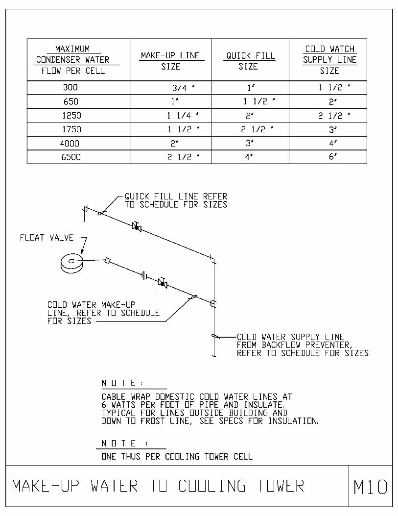
MAXIMUMMAKE-UP LINE QUICK FILL
COLD WATCH
CONDENSER WATER SUPPLY LINESIZE SIZE
FLOW PER CELL SIZE
300 3/4 " 1" 1 1/2 "
650 1" 1 1/2 " 2"
1250 1 1/4 " 2" 2 1/2 "
1750 1 1/2 " 2 1/2 " 3"
4000 2" 3" 4"
6500 2 1/2 " 4" 6"
QUICK FILL LINE REFERTO SCHEDULE FOR SIZES
FLOAT VALVE
COLD WATER MAKE-UPLINE, REFER TO SCHEDULEFOR SIZES
N O T E :
COLD WATER SUPPLY LINEFROM BACKFLOW PREVENTER,REFER TO SCHEDULE FOR SIZES
CABLE WRAP DOMESTIC COLD WATER LINES AT6 WATTS PER FOOT OF PIPE AND INSULATE.TYPICAL FOR LINES OUTSIDE BUILDING ANDDOWN TO FROST LINE, SEE SPECS FOR INSULATION.
N 0 T E
ONE THUS PER COOLING TOWER CELL
VAKE -UP WATER TO COOLI\G TOWER v1:

120-1-60 PWRSUPPLY TOBLEED VALVE
CONTROL PANEL(WALL MOUNTED)
COOLING WATERSENSOR PIPING
120-1-60POWER
3/4 ' CHEMICALFEED PIPING
UNION
CHECKVALVES
IN
OUT
CHEMICALFEEDPUMPS
0
CHEMICAL SPILLPALLET
55 GALLONCHEMICAL DRUM(TYPICAL)
NOTE:PROVIDE FEED PUMP FOR EACH COOLING TOWER
COOLI\G TOWER CHEVICAL FEED PUVP X11

INCREASE VENT LINEONE SIZE FOR EACHRELIEF VENT GANGEDTOGETHER
TERMINATE 6'ABOVE ROOF
f
STRUCTURE
DO NOT REDUCE PIPESIZE FROM DRIP PANELL CONN. SIZE
RELIEF VALVESIZE PERASME CODE
VALVEBODYDRAIN
//./l' PIPE TOFLOOR DRAIN
f
DISCHARGE PIPEMIN. ONE PIPE SIZELARGER THAN RELIEFVALVE OUTLET
INDIRECT CONNECTION,RELIEF VALVE SHALLBEAR NO PIPING WEIGHT
3/4 ' DRAIN
UNIONTYPICAL
STEAV RELIEF VALVE V12
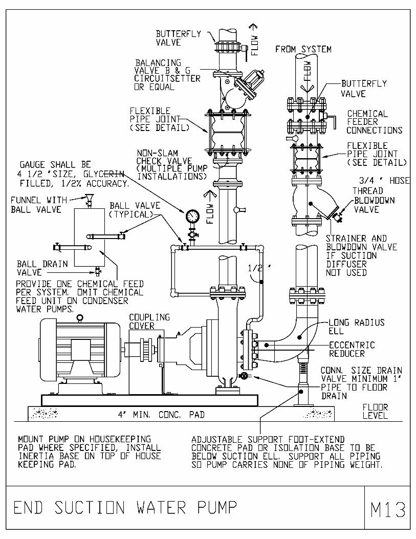
GAUGE SHALL BE4 1/2 "SIZE, GLYCFILLED, 1/2% ACCURACY.
FUNNEL WITHBALL VALVE
BUTTERFLY m\VALVE
BALANCINGVALVE B & GCIRCUITSETTEROR EQUAL
FLEXIBLEPIPE JOIN(SEE DETAIL)
NON-SLAMCHECK VALVE(MULTIPLE PUMPINSTALLATIONS)
WWWWFmU-
N
FROM SYSTEM
IIMIMN:q1
-1001urpr-vi
BUTTERFLYVALVE
CHEMICALFEEDERCONNECTIONS
FLEXIBLEPIPE JOINT(SEE DETAIL)
BALL VALVE(TYPICAL)
U_
BALL DRAINVALVE
PROVIDE ONE CHEMICAL FEEDPER SYSTEM. OMIT CHEMICALFEED UNIT ON CONDENSERWATER PUMPS.
COUPLINGCOVER
MIN. CONC. PAD
MOUNT PUMP ON HOUSEKEEPINGPAD WHERE SPECIFIED, INSTALLINERTIA BASE ON TOP OF HOUSEKEEPING PAD.
3/4 ' HOSETHREADBLOWDOWNVALVE
STRAINER ANDBLOWDOWN VALVEIF SUCTIONDIFFUSERNOT USED
LONG RADIUSELL
ECCENTRICREDUCER
CONN. SIZE DRAINVALVE MINIMUM 1'PIPE TO FLOORDRAIN
FLOORLEVEL
ADJUSTABLE SUPPORT FOOT-EXTENDCONCRETE PAD OR ISOLATION BASE TO BEBELOW SUCTION ELL. SUPPORT ALL PIPINGSO PUMP CARRIES NONE OF PIPING WEIGHT.
E\ D SUCTIU\ WATER PUVP X13
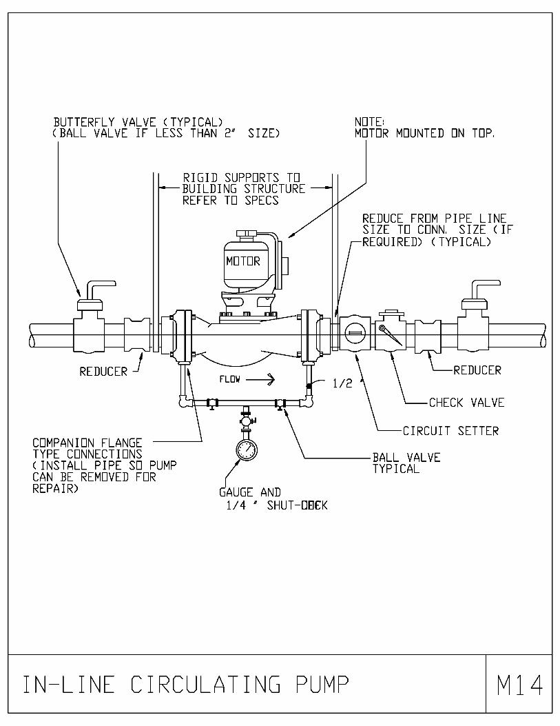
BUTTERFLY VALVE (TYPICAL) NOTE:(BALL VALVE IF LESS THAN 2' SIZE) MOTOR MOUNTED ON TOP.
_1 L
REDUCER
RIGID SUPPORTS TOBUILDING STRUCTURE -REFER TO SPECS
COMPANION FLANGETYPE CONNECTIONS(INSTALL PIPE SO PUMPCAN BE REMOVED FORREPAIR)
FLOW .-
ci F5
REDUCE FROM PIPE LINESIZE TO CONg SIZE (IFREQUIRED) (TYPICAL)
GAUGE AND1/4 ' SHUT-OECK
1 L
\--REDUCER
CHECK VALVE
CIRCUIT SETTER
BALL VALVETYPICAL
I\LI\E CIRCULATI\G PUMP X14

N O T EINLET STRAINER & SHUTOFF VALVE ARE SHOWN.(REPLACE WITH SUCTION DIFFUSER IF INDICATED.)
BUTTERFLYVALVE
Qtr n
11
SPOOLPIECE
PIPE JOINT/FLEXIBLE
(SEE DETAIL)
II II
vBALL VALVE
\e low
STRAINER &BLOWDOWNVALVE, SEENOTE ABOVE
DRAINVALVE
PROVIDE ONE CHEMICAL FEEDERPER SYSTEM. OMIT CHEMICALFEEDER ON CONDENSER WATERPUMPS.
BUTTERFLYFUNNEL VALVE
BALL VALVE II
1=1
U-
BALANCINGVALVE B & GCIRCUITSETTEROR EQUAL
PRESSURE GAUGETAP FLANGES &1/4" GAUGE COCK.FOR PRESSURE GAUGE SHALL BEFORGE 41/2" SIZE, GLYCERI
FILLED, 1/2 ZBALL U ACCURACY.VALVE AIR VENTTYPICAL\ COCK
4:41111t
3/4 HTHREADBLOWDOWNVALVE
LONGRADIUSELL
FLEXIBLEPIPEJOINT(SEEDETAIL)
1/
NONSLAMCHECK VALVE(MULTIPLE PUMPINSTALLATIONS)
ADJUSTABLEPIPE SUPPORTTYPICAL
ECCENTRICREDUCER CONCENTRIC
REDUCER
MIN. CONCPADCONRVALVE MIR
SIZE DRAIN1' PIPE PIPE GLAND MOUNT PUMP ON HOUSEKEEPING PAD
DRAIN TO BASE WHERE SPECIFIED, INSTALL INERTIA BASETO NEARESTFLOOR DRAIN ( CONR SIZE ) ON TOP OF HOUSEKEEPING PAD.
PPE SUPPORTS SHALL CARRY ALL OF THE PIPING WEIGHT, SO THATNONE OF IT RESTS ON THE PUMP. IF ISOLATION BLOCK IS USED,THESE SUPPORTS SHALL REST ON THE ISOLATION BLOCK.
LONGRADIUSELL
PIPE DRIP LIPCONR SIZE TOFLOOR DRAIN
DRIP LIP BASE FLOOR LEVEL
DOUBLE SUCTIO\( WITH Y-STRAI\
WATER PUVPER)
X15

N O T EINLET STRAINER & SHUTOFF VALVE ARE SHOWN.(REPLACE WITH SUCTION DIFFUSER IF INDICATED.)
SPOOLPIECE
1=1
U_
r n
BUTTERFLYVALVE
BALL VALVE
FUNNEL
FLEXIBLEPIPE JOIN(SEE DETAIL)
THIS CONN. SIZESHALL BE SAMESIZE AS PIPE SIZE.
COMBINATIONINLET ELL &STRAINER.SIZE FOR MAX.1 PSI P.
STRAINERBASKETPULL AREAKEEP CLEAR
DRAINVALVE
TAP FLANGESFOR PRESSUREGAUGE
BALLVALVETYPICAL\
PROVIDE ONE CHEMICAL FEEDERPER SYSTEM. OMIT CHEMICALFEEDER ON CONDENSER WATERPUMPS, OT
BUTTERFLYVALVE
BALL VALVE
BALANCINGVALVE B & GCIRCUITSETTEROR EQUAL
PRESSURE GAUGE&1/4' GAUGE COCK.GAUGE SHALL BE41/2' SIZE, GLYCERIFILLED, 1/2 ZACCURACY.
AIR VENTCOCK
NON-SLAMCHECK VALVE(MULTIPLE PUMPINSTALLATIONS)
U_
FLEX-IBLEPIPEJOINT(SEEDETAIL)
CONCENTRICREDUCER
ADJUSTABLEPIPE SUPPORTTYPICAL
4' MIN. CONCPADCONK SIZE DRAINVALVE MIN. 1' PIPE PIPE GLAND
TO NEAREST DRAIN TO BASEFLOOR DRAIN ( CONN. SIZE )
PPE SUPPORTS SHALL CARRY ALL OF THE PIPING WEIGHT, SO THATNONE OF IT RESTS ON THE PUMP. IF ISOLATION BLOCK IS USED,THESE SUPPORTS SHALL REST ON THE ISOLATION BLOCK.
DRIP LIP BASE
LONGRADIUSELL
PIPE DRIP LIPSIZE TO
FLOOR DRAIN
FLOOR LEVEL
MOUNT PUMP ON HOUSEKEEPING PADWHERE SPECIFIED, INSTALL INERTIA BASEON TOP OF HOUSEKEEPING PAD.
DOUBLE SUCTION WATER PUMP(WITH SUCTION DIFFUSER) 16

GATE VALVE AND
STRAINER IN HORIZONTAL
BRANCH PIPING CONNECTED
TO TOP OF STEAM MAIN
2 WAY CONTROL VALVE TO
CLOSE WHEN AHU
USES MECHANICAL
COOLING.
INSULATE ALL EXPOSED
PIPING PER SPECIFICATIONS
TO CONDENSATE
COOLER, CONDENSATE
MAIN, OR CONDENSATE
RETURN UNITCONTROL VALVE
BY HUMIDIFIER
MFR.
CHECK VALVE
(TYP.)
MINN
IVB TRAP
F&T TRAP
pIr
bi--
IF STEAM MAIN
1.1
ENDS AT A/C, PROVIDE-'''L)
END-OF-MAIN
DRIP
STEAM MAIN
111111
o
1
00
000
°AIR FLOW
1111
o
*---LINE SIZE
DIRT LEG
A/C CASING
PENETRATION
3/4 ' CONDENSATE
PIPING
20 GA.
GALVANIZED SHEETMETAL
BLANK-OFF TO A/C CASING.
HUMIDIFIER UNIT SHALL EXTEND
TO WITHIN 3' OF TOP AND SIDES
OF A/C CASING.
INSTALL DISPERSION TUBES TO DISCHARGE
UPSTREAM INTO AIR FLOW
MOUNT HEADER MIN,
6' ABOVE
A/C UNIT FLOOR,
CONDENSATE PIPING
SHALL BE ALL WELDED INSIDE A/C CASING.
INSULATE STEAM HEADER AND CONDENSATE
PIPING PER SPECS FOR INSULATION OF
PIPING.
PROVIDE 20 GA.
GALVANIZED
SHEETMETAL BLANK-OFF TO A/C
CASING SIDES AND BOTTOM UPSTREAM
OF HEADER] BLANK-OF TO BE
REMOVEABLE WITH SCREWS,
A/C UNIT MOUNTED HUMIDIFIER
M17

AUTOMATIC CONTROLVALVE ASSEMBLY(SEE DETAIL)
STEAMSUPPLY
CONVERTORSEE SCHEDULEFOR SELECTION
F & T TRAPS
MATCH TRAP RATEDW. P. TO PRESSURE OFSTEAM ENTERINGCONTROL VALVE. REFERTO SCHEDULE FORNUMBER AND SIZE.
UNION(TYR )-7
STRAINER(TYPICAL)
DIRT LEG
REMOVE CAP DURINGSTART UP TO BLOWOUT STEAM LINES
LOCATE CONVERTOR SO THAT TUBE BUNDLECAN BE REMOVED WITHOUT INTERFERENCE
CONDENSATERETURN
STEAv PIPI\G AT CO\VERTOR X18

N 0 T E :
PROVIDE CONTROL VALVE #2 ONLY WHERECALLED FOR ON PLANS, OTHERWISE OMIT IT.
BYPASS LINESAME SIZE LINEAS LARGERCONTROL VALVE
CONTROL VALVE #2
PROVIDE
I(-
CONTROL VALVEIMMEDIATELYAFTER 90
COCKCK( TYP.)
UNION( TYR )
CONCENTRICREDUCER (TYP.)
-OMIT ON SINGLECONTROL VALVEASSEMBLIES
N 0 T E :
ECCENTRICREDUCER (TYR.)
CONTROL VALVE #1
SIZE ONE CONTROL VALVE FOR /3 FLOW AND ONEFOR 73 FLOW, PIPE SIZE TO EACH VALVE SHALLBE BASED ON SAME PRESSURE DROP AND VELOCITYAS IN THE MAIN SUPPLYING BOTH VALVES.
STEAMSUPPLY
GATE VALVE(TYP. )
STRAINER &BLOWDOWNVALVE (TYP. )
AUTOASS(
VATIC STEAV CO\TROL VALVEVBLY (PARALLEL CO\TROL VALVES) X19

AUTOMATIC STEAMCONTROL VALVEASSEMBLY
( SEE DETAIL )
45°/90°ELL
1/2' CHECK VALVEVACUUM BREAKER
( PREHEAT COIL ONLY )
PROVIDE TRAP & DIRT LEGIF DROP EXCEEDS 36'
STEAM MAIN
* UNION
STRAINER PROVIDE MIN. 12'
DIRT LEG ONPREHEAT COILS
LINE SIZEDIRT LEG
F & T TRAP REFER TOSCHEDULE FOR SIZES
F&T TRAPS
REMOVE CAP DURINGSTART-UP TO BLOWOUT STEAM LINES.
MATCH TRAP RATED W. P.TO PRESSURE OF STEAMENTERING CONTROL VALVE.
TO CONDENSATE RETURN.DO NOT LIFT CONDENSATE PIPINGSLOPE DOWN WITH FLOW.
* PROVIDE FLANGE CONNECTIONS ONPIPE SIZES 1 1/2' AND ABOVE,PIPE SIZES SMALLER THAN 1 1/2'MAY USE UNIONS.
STEAv PIPI\G AT HEATING COIL V

F&T TRAPS
MATCH TRAP RATED W. P.TO PRESSURE OF STEAMENTERING CONTROL VALVE,
AUTOMATIC STEAMCONTROL VALVE w COMPANIONASSEMBLY (SEE DETAIL) FLANGE
(TYPICAL)
* PROVIDE FLANGECONNECTIONS FOR PIPESIZES 1 1/2' AND ABOVE,PIPE SIZES SMALLERTHAN 1 1/2" MAY USEUNIONS,
45° OR
90°ELL
STEAM MAIN
PROVIDE MIN. 12"
DIRT LEG ONPREHEAT COILS
STRAINER(TYPICAL)
1/2 ' CHECK VALVEVACUUM BREAKER(PREHEAT COIL ONLY)
PROVIDE ONLY ONSTACKED COILSSERVED FROM ABOVE----7
1/2"VACUUM
REMOVE CAP DURINGSTARTUP TO BLOWOUT STEAM LINES.
TO CONDENSATE RETURN.DO NOT LIFT CONDENSATE PIPINGSLOPE DOWN WITH FLOW.
UNION(TYPICAL)
F&T TRAPREFER TO SCHEDULEFOR SIZE AND QUANTITY
STEAv PIPI\G AT HORIZO\TALvULTIPLE HEATI\G COILS
X21

AUTOMATIC STEAMCONTROL VALVEASSEMBLY
( SEE DETAIL )
45°/90°ELL
1/2' CHECK VALVEVACUUM BREAKER
( PREHEAT COIL ONLY )
PROVIDE TRAP & DIRT LEGIF DROP EXCEEDS 36'
STEAM MAIN
* UNION
STRAINER PROVIDE MIN. 12'
DIRT LEG ONPREHEAT COILS
LINE SIZEDIRT LEG
F & T TRAP REFER TOSCHEDULE FOR SIZES
F&T TRAPS
REMOVE CAP DURINGSTART-UP TO BLOWOUT STEAM LINES.
MATCH TRAP RATED W. P.TO PRESSURE OF STEAMENTERING CONTROL VALVE.
TO CONDENSATE RETURN.DO NOT LIFT CONDENSATE PIPINGSLOPE DOWN WITH FLOW.
* PROVIDE FLANGE CONNECTIONS ONPIPE SIZES 1 1/2' AND ABOVE,PIPE SIZES SMALLER THAN 1 1/2'MAY USE UNIONS.
STEAv PIPI\G AT HEATING COIL V22
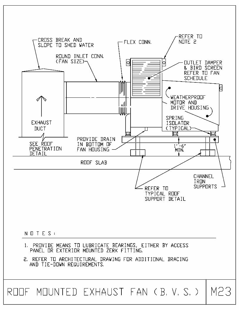
CROSS BREAK ANDSLOPE TO SHED WATER
ROUND INLET CONN.(FAN SIZE)
IEXHAUSTDUCT
FLEX CONN.
0
SEE ROOFPENETRATIONDETAIL
PROVIDE DRAININ BOTTOM OFFAN HOUSING
ROOF SLAB
REFER TONOTE 2
OUTLET DAMPER& BIRD SCREENREFER TO FANSCHEDULE
(-WEATHERPROOFMOTOR ANDDRIVE
H
SPRINGISOLATOR
NOTES:
Ittl' -6'MIN.
i
REFER TOTYPICAL ROOFSUPPORT DETAIL
CHANNELIRONSUPPORTS
1, PROVIDE MEANS TO LUBRICATE BEARINGS, EITHER BY ACCESSPANEL OR EXTERIOR MOUNTED ZERK FITTING.
2. REFER TO ARCHITECTURAL DRAWING FOR ADDITIONAL BRACINGAND TIE-DOWN REQUIREMENTS.
ROOF vOU\TED EXHAUST FA\ ( B, V, S, ) v23
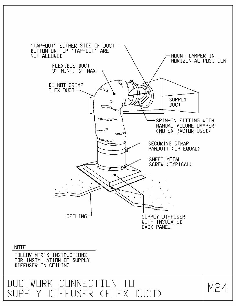
"TAP-OUT" EITHER SIDE OF DUCT.BOTTOM OR TOP "TAP-OUT" ARENOT ALLOWED
FLEXIBLE DUCT3' MIN., 6' MAX.
DO NOT CRIMPFLEX DUCT
MOUNT DAMPER INHORIZONTAL POSITION
SUPPLYDUCT
SPIN-IN FITTING WITHMANUAL VOLUME DAMPER(NO EXTRACTOR USED)
SECURING STRAP., PANDUIT (OR EQUAL)
SHEET METALSCREW (TYPICAL)
CEILIN
NOTE
FOLLOW MFR'S INSTRUCTIONSFOR INSTALLATION OF SUPPLYDIFFUSER IN CEILING
SUPPLY DIFFUSERWITH INSULATEDBACK PANEL
DUCTWORK CON\ECTIO\ TOSUPPLY DIFFUSER (FLEX DUCT)
v 24
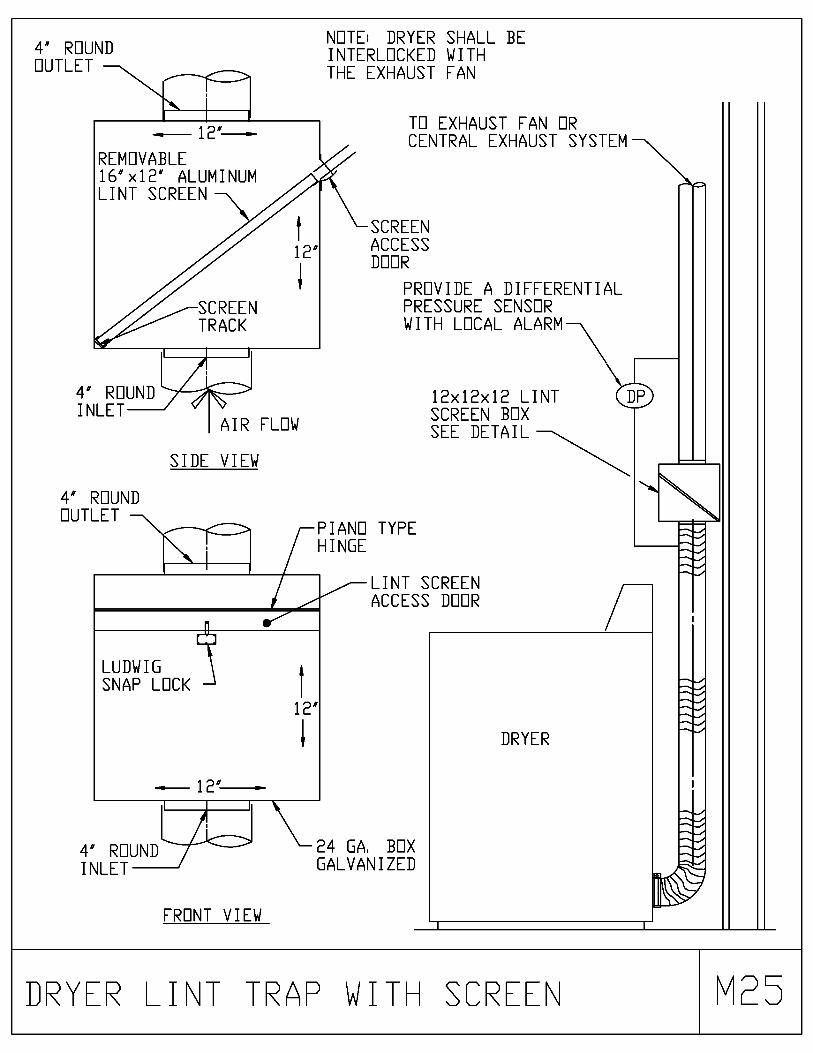
4' ROUNDOUTLET >
NOTE: DRYER SHALL BEINTERLOCKED WITHTHE EXHAUST FAN
REMOVABLE16'x12' ALUMINUMLINT SCREEN
4' ROUNDINLET
4' ROUNDOUTLET
AIR FLOW
SIDE VIEW
TO EXHAUST FAN ORCENTRAL EXHAUST SYSTEM
SCREENACCESSDOOR
PROVIDE A DIFFERENTIALPRESSURE SENSORWITH LOCAL ALARM
PIANO TYPEHINGE
LUDWIG IA
SNAP LOCK
12'
1
12'
4' ROUNDINLET
FRONT VIEW
12x12x12 LINTSCREEN BOXSEE DETAIL
LINT SCREENACCESS DOOR
24 GA. BOXGALVANIZED
DP
DRYER
DRYER LI\T TRAP WITH SCREE\ X25

NOTE:DISCHARGE SHALL BE LOCATEDA MIN. OF 10' ABOVE ROOFLEVEL AND 100' FROM THENEAREST OUTSIDE AIR INTAKE
FLASH SLEEVE INTOROOF WATERTIGHT
ROOF
FLAPPER
COUNTER FLASHCOLLAR WELDEDTO PIPE
EXHAUST PIPE& INSULATION
SLEEVE, MIN. 4' LARGER THAN 0. D.OF INSULATED GENERATOR PIPE,SHALL EXTEND 12' ABOVE ROOF
EVERGE \CY GE\ERATORvUFFLER EXHAUST PIPE v26
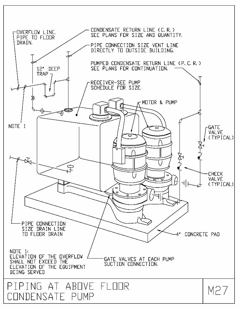
OVERFLOW LINE.PIPE TO FLOORDRAIN.
CONDENSATE RETURN LINE (C. R. )SEE PLANS FOR SIZE AND QUANTITY.
PIPE CONNECTION SIZE VENT LINEDIRECTLY TO OUTSIDE BUILDING.
PUMPED CONDENSATE RETURN LINE ( P. C. R. )SEE PLANS FOR CONTINUATION.
RECEIVER-SEE PUMPSCHEDULE FOR SIZE.
MOTOR & PUMP
NOTE 1
VALVE(TYPICAL)
PIPE CONNECTIONSIZE DRAIN LINETO FLOOR DRAIN
NOTE 1:ELEVATION OF THE OVERFLOWSHALL NOT EXCEED THEELEVATION OF THE EQUIPMENTBEING SERVED
GATE VALVES AT EACH PUMPSUCTION CONNECTION.
CHECKVALVE(TYPICAL)
CONCRETE PAD
PIPI\G AT ABOVE FLOORCO\DE\SATE PU'P
V27
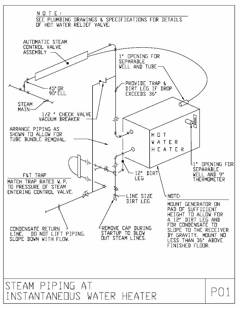
N O T E :
SEE PLUMBING DRAWINGS & SPECIFICATIONS FOR DETAILSOF HOT WATER RELIEF VALVE.
AUTOMATIC STEAMCONTROL VALVEASSEMBLY
45° OR90°ELL
1' OPENING FORSEPARABLEWELL AND TUBE
.----1.----- ,c-PROVIDE TRAP &dr DIRT LEG IF DROP
EXCEEDS 36'
STEAMMAIN
1/2 ' CHECK VALVEVACUUM BREAKER
ARRANGE PIPING ASSHOWN TO ALLOW FORTUBE BUNDLE REMOVAL.
F&T TRAP
H 0 T
WATERHEATER
MATCH TRAP RATED W. P.TO PRESSURE OF STEAMENTERING CONTROL VALVE.
CONDENSATE RETURNLINE. DO NOT LIFT PIPING.SLOPE DOWN WITH FLOW.
12' DIRTLEG
LINE SIZEDIRT LEG
REMOVE CAP DURINGSTARTUP TO BLOWOUT STEAM LINES.
-1' OPENING FORSEPARABLEWELL AND 9'THERMOMETER
NOTE:
MOUNT GENERATOR ONPAD OF SUFFICIENTHEIGHT TO ALLOW FORA 12' DIRT LEG ANDFOR CONDENSATE TOSLOPE TO THE RECEIVERBY GRAVITY. MOUNT NOLESS THAN 36' ABOVEFINISHED FLOOR.
STEAV PIPI\G ATI\STA\TA\EOUS WATER HEATER P:1

BRACE TH MALE RIGID
la I I', S, STAY UPENVALVE
CEILING FERRULE
PULL RED
E, S, E Y, VALVELULLED IN UPENPUSITIUN
SUPPLY PIPE
FLEW SENSURREPORTING TEDELTA (FMS)
CEILING
BARRv R-
]
R
\AI R P OP

PRESSURE
REGULATOR
(TYP)
PRV PIPED TO OUTSIDE
DC BUILDING
REGULATER
(TYP 2)
PRESS,
CAGE
14-
DEMAND
CHECK
(TYP)
PRESSURE SWITCH
CENN,
TO MASTER
ALARM PANEL
NC NC
IN1,1
HIGH PRESSURE HEADER
CYLINDERS NE
1BANK
SHUTOFF VALVE
(TYP)
CHECK VALVE
(TYP)
CYLINDER VALVE
(TYP)
PRESSURE RELIEF
DEVICE (TYP)
SEURCEll
VALVE
50 TO 55 PSI
TO FACILITY
f,z-CHANEEDVER ACTUATING
SWITCH (TYP)
1-6)
HIGH PRESSURE HEADER
1
CYLINDERS NE
2 BANK
VD
CA
L C
AS
VA
\L
DP
03
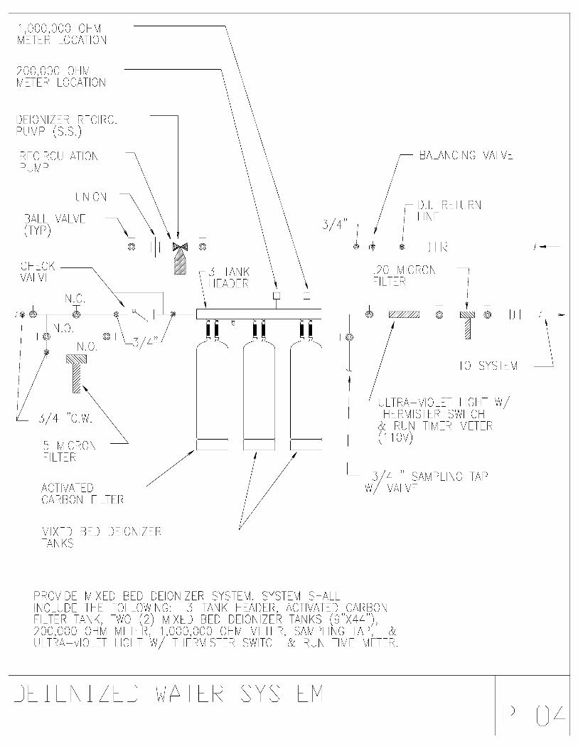
1,000,000 0 VMETER LOCATION
200,000 0 MNETER LOCATION
DEION ZER RECIRC.PUMP (S.S.)
RECPUN
RCULATP
ON
UNION
BALL VALVE(TYP)
C ECKVALVE
N.C.
BALANCING VALVE
D. . RETURNNE
1+1 DIR
3-TANKFADER
.20 MICRONF LTER
5 M CRONF LTER
ACTIVATEDCARBON F LTER
M XED BED DEIONTANKS
ZER
TO SYSTEM
ULTRA-V OLET L 0 TT ERM STER SWITCH& RUN TIMER METER(1 10V)
3/4 SAN/PEW/ VALVE
PROV DE V XED BED DE ON ZER SYSTEM. SYSTEM S ALLINCLUDE T E FOLLOW NG: 3-TANK FADER, ACT VATED CARBONE LTER TANK, TWO (2) M XED BED DE ON ZER TANKS (9"X44"),200,000 0 V METER, 1,000,000 OHM METER, SAVPL NG TAP, &ULTRA-v OLET LC T W/ T ERM STER SW TC & RUN THE METER.
NG TAP
D \ I / D S V S V
P 04

CONNECT AT TOP UP PIPESERVING A PERKING FIXTURETE PREVENT FEREIEN MATERIALFREM ENTERING INTE PRIMER
FLHER DRAIN TRAP PRIMERDISTRIBUTION UNITS. ANC HRTE WALL N SEE FLEER PLANSFER NUMBER HE LINES REQUIRED
PIPINE ROUTEDWITHIN WALL
RUN TE P-TRAPEN FLEDR DRAIN
TRAP PRIMER VALVEANC-ER TEl WALL(SEE SPECIFICATIONS)
EINISFLEER
NNE:TRAP PRIMER N DISTRIBUTIDNUNITS TE BE LEGATED ABOVE ANACCESIBLE CEILING
ED
TRAP PR V D SIR E TP Pi
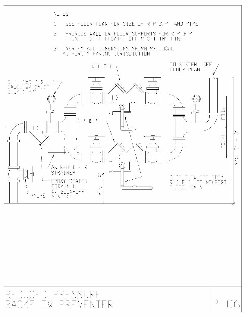
NETES!
1 SEE FLOUR PLAN PER SIZE E R P B P P, AND PIPE,
2, PROVIDE WALL ER FLAIR SUPPORTS FOR R P B P.
IF UNIT IS TE LEDA-TB BELEW CEILING LINE,
3 VERIFY ALL DIMENSIONS S-OWN W/ FECALAUT ORITY HAVING JURISDICTION,
0 TO 150 P. S I G
GAUGE W/ GAUGEGEC< (TYP)
R. P B.TE SYSTEM, SEEFLOOR PLAN
-,....._____.---- -------1
R P B. P
AS REU'D FORSTRAINER
EPDXY COATEDSTRAINERW/ BLEW-EFF
VALVE MIN, 2,
171
l
P
J
----____.----
J
Li
PIPE BLEW-EFF FREMR. P B, P TO NEARESTFLOOR DRAIN
,0
in
R DRA'
\__/ \__/ D PRW P R
s S-v R
\T -R P 06
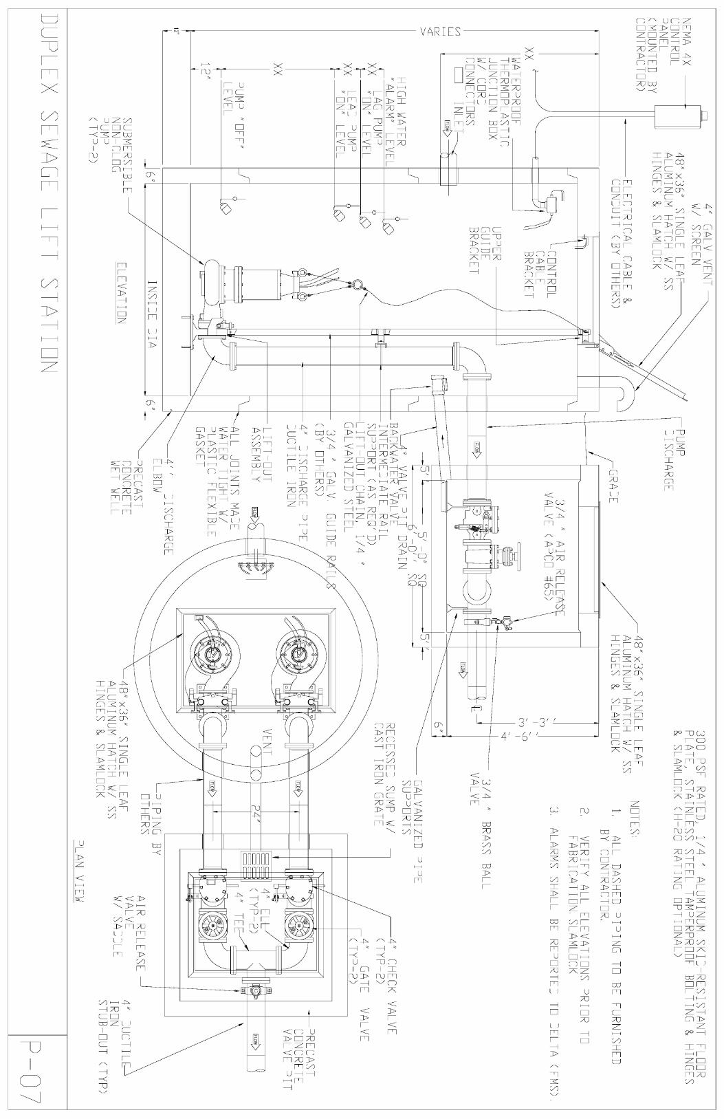
NEMA 4X
CONTROL
PANEL
(MOUNTED BY
CONTRACTOR)
4"
GALV VENT
W/ SCREEN
48"x36" SINGLE LEAF
ALUMINUM -ATC- W/ SS
HINGES U SLAMLEC<
puvp
DISCHARGE
ELECTRICAL CABLE
CENDUIT (BY ET ERS)
=hi
300 PS- RATED,
1/4
"ALUMINUM S<ID-RESISTANT
PLATE, STAINLESS STEEL TAMPERPROOF BELTING
U SLAMLEC< (
-20 RATING OPTIONAL)
48"x36" SINGLE LEAF
ALUMINUM HATCH W/ SS
INGES U SLAMLEC<
[GRADE
XX
1-1
-11
WATERPRJE
T-ERMEPLASTIC
JUNCTION BOX
W/ CURD
CONNECTORS
INLET
b
CONTROL
CABLE
BRAC<ET
UPPER
GUIDE
BRAC<ET
=LEER
INGES
NETES!
1ALL DAS ED PIPING TE BE EURNIS ED
BY CONTRACTOR.
2,
VERIFY ALL ELEVATIONS PRIER TE
FABRICATION, SLAMLEIC<
3ALARMS SHALL BE REPORTED TO DELTA (FMS),
3/4
"BRASS BALL
VALVE
IG
WATER
"ALARM" LEVEL
XX LAG PUMP
ON" LEVEL
xx
LEAD PUMP
ON
LEVEL
XX
12"
PUMP "OFF"
LEVEL
5''
5'
0"
SE
0'
/
SU
4" VALVE PIT DRAIN
BAC<WATER VALVE
INTERMEDIATE RAIL
SUPPORT (AS RETD)
LIFT OUT C-AIN,
1/4
GALVANIZED STEEL
3/4
"GALV
GUIDE
(BY ET-ERS)
4" DISC-AKE PIPE
DUCTILE IREN
LIFT OUT
ASSEMBLY
IFLoi>
GALVANIZED PIPE
SUPPORTS
RECESSED SUMP W/
CAST IRON GRATE
4"
C EC< VALVE
(TYP-2)
4"
GATE
VALVE
(TYP-2)
---PRECAST
CONCRETE
VALVE PIT
ALL JOINTS MADE
WATER TIG-T W/
PLASTIC
LEXIBLE
GAS<ET
12"
SUBMERSIBLE
NON -CLOG
PUMP
(TYP-2)
ELEVATION
4"
DISC
ELBOW
PRECAST
CONCRETE
WET WELL
ARGE
PIPING BY
ETHERS
48"x36" SINGLE LEAF
ALUMINUM -ATC- W/ SS
-INGES U SLAMLEC<
AIR RELEASE
VALVE
W/ SADDLE
PLAN VIEW
4"
DUCTILE
IRON
STUB-PUT (TYP)
PS
WAS
F

SEE ELDERPLAN FURCONTINUATION
IGH WATER ALARM MOUNTEDSN ELEVATOR SHAFT WALL
ELECTRICAL CUTLETSUNDER DIVISION 16 OFSPECIFICATIONS
GATE VALVE
FINIS ED FLEER
x\HIGH WATERLEVEL ALARM
6"
PUMP, SEESC EDULE
I I I
\----RFINFEIRCFDCONCRETEPIT
NETES
1, ALARMS S
C FC VALVE
UNILN,TYPICAL
REINFORCEDCONCRETESUMP PIT
3/16 " AIRBLEED IDLE
ALL BE REPORTED TE DELTA (EMS)
D S vp P VPP OH
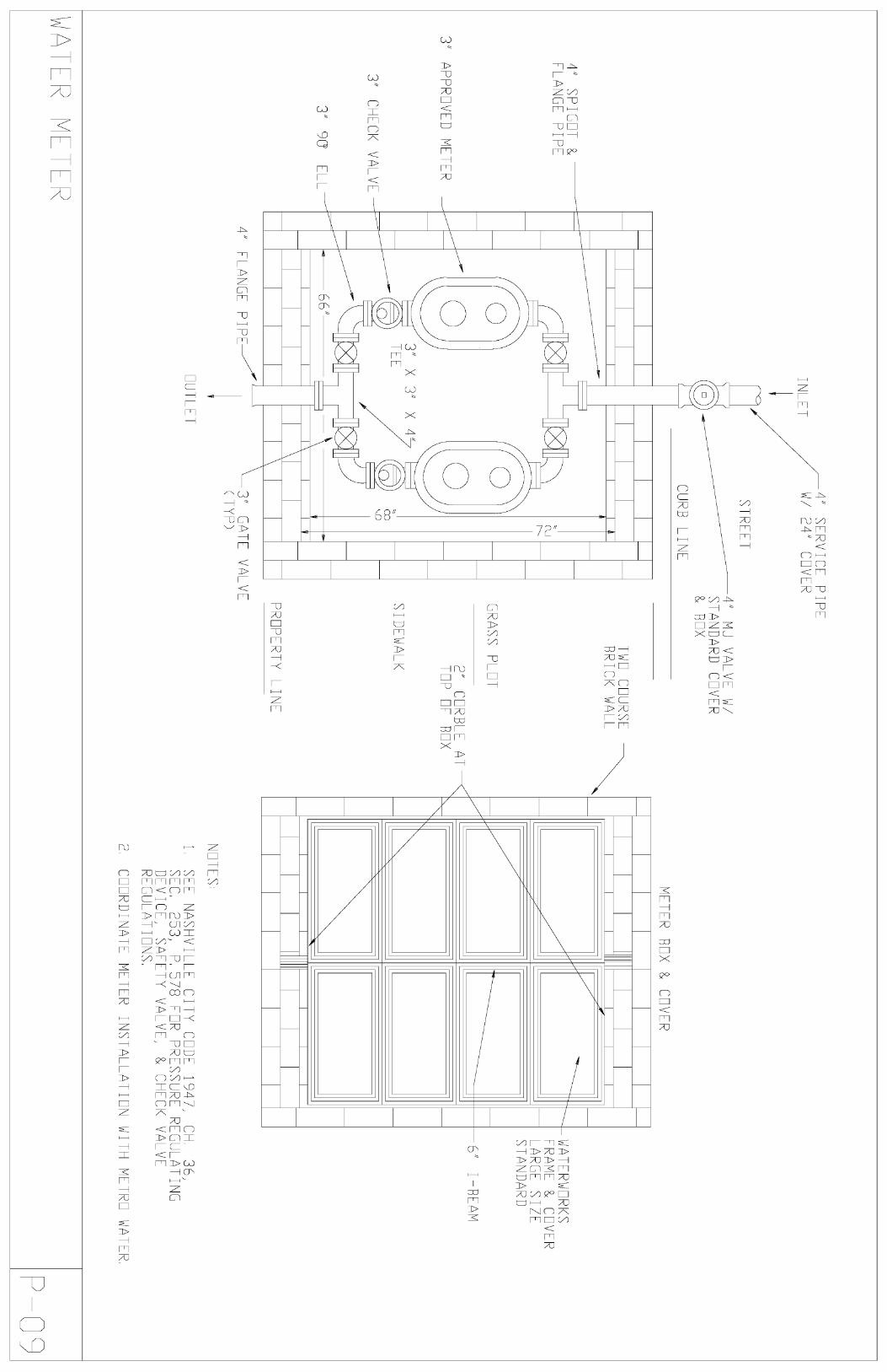
4"
SPIGET
FLANGE PIPE
3" APPROVED METER
3"
CEC< VALVE
3" 9J
ELL
INLET
4"
SERVICE PIPE
W/ 24" LEVER
STREET
CURB LINE
4"
MJ VALVE W/
STANDARD COVER
R BOX
3"
X 3"
X
EDTEE
IRE COURSE
BRIC< WALL
GRASS PVT
2" CURBLE AT
TOP OF BOX
SIDEWAL
PROPERTY LINE
4" FLANGE PIPE--
CUTLET
3"
GATE VALVE
(TYP)
METER BOX E COVER
WATERWER<S
FRAME R LEVER
LARGE SIZE
STANDARD
NETES
6"
I-BEAM
1SEE NAS VILLE CITY CEDE 1947,
C-,
36,
SEC,
253,
P, 578 =ER PRESSURE REGULATING
DEVICE, SAFETY VALVE,
E C ECK VALVE
REGULATIENS.
2,
COORDINATE METER INSTALLATION WIT
METRE WATER
WA
V
P 0

Appendix
B
Patient Care FacilityMechanical Design Guidelines
And Construction StandardsVUMC 06/21/13
BSL-3 Laboratory Design Schematic
75

BS
L-3 DE
SIG
N G
EN
ER
AL N
OT
ES
1.A
LL DE
VIC
ES
, SU
CH
AS
AIR
VA
LVE
S, R
EH
EA
T C
OILS
,V
ALV
ES
, ET
C., T
HA
T R
EQ
UIR
E M
AIN
TE
NA
NC
E S
HA
LL BE
LOC
AT
ED
OU
TS
IDE
OF
TH
E B
SL-3 LA
B A
ND
TH
E A
NT
ER
OO
M.
2.O
NE
PA
IR O
F F
AN
S S
HA
LL BE
PR
OV
IDE
D F
OR
EA
CH
BS
L-3 LAB
.G
AN
GIN
G M
ULT
IPLE
LAB
S O
N C
OM
MO
N F
AN
SIS
NO
T A
CC
EP
TA
BLE
.3.
LAB
EX
HA
US
T A
IR S
HA
LL BE
CO
NS
TA
NT
VO
LUM
E W
ITH
AIR
VA
LVE
S T
O G
AU
RA
NT
EE
PR
OP
ER
FLO
W.
4.E
AC
H LA
B S
HA
LL BE
PR
OV
IDE
D W
ITH
A LA
B A
IRP
RE
SS
UR
E M
ON
ITO
R A
ND
CO
NT
RO
LLER
.T
HE
CO
NT
RO
LLER
SH
ALL M
AIN
TA
IN T
HE
TH
E D
ES
IRE
D P
RE
SS
UR
E D
IFF
ER
EN
TIA
L(-0.075" W
.G. A
DJ.) B
Y M
OD
ULA
TIN
G T
HE
SU
PP
LY A
IRV
ALV
E.
5.P
OS
ITIV
E S
EA
L DA
MP
ER
S S
HA
LL BE
CA
PA
BLE
OF
OP
ER
AT
ING
AT
NO
MO
RE
TH
AN
30 PS
I CO
NT
RO
L AIR
.6.
UN
INT
ER
UP
TIB
LE P
OW
ER
SO
UR
CE
S (U
PS
')S
HA
LL BE
PR
OV
IDE
D O
N A
LL EX
HA
US
T E
QU
IPM
EN
T, B
IOLO
GIC
AL S
AF
ET
YC
AB
INE
TS
, CO
NT
RO
LS D
EV
ICE
S, C
ON
TR
OL P
AN
ELS
, ET
C. T
OIN
SU
RE
TH
AT
EX
HA
US
T A
IR F
LOW
IS N
OT
INT
ER
UP
TE
D B
Y A
LOS
S O
F N
OR
MA
L PO
WE
R.
7.P
OW
ER
FO
R E
AC
H B
SL-3 LA
B S
HA
LL BE
FE
ED
FR
OM
A D
ED
ICA
TE
D E
LEC
TR
ICA
L PA
NE
L.T
HIS
PA
NE
L SH
OU
LD B
ELO
CA
TE
D IN
TH
E A
NT
E R
OO
M.
8.E
XH
AU
ST
FA
NS
SH
ALL D
ISC
HA
RG
E N
O LE
SS
TH
AN
10'-0" AB
OV
E T
HE
RO
OF
LEV
EL A
ND
TH
E S
TA
CK
VE
LOC
ITY
SH
OU
LD B
E N
O LE
SS
TH
AN
4,000 FP
M.
TH
E D
ES
IGN
ER
SH
OU
LD A
CC
OU
NT
FO
R E
XC
ES
SIV
E S
TA
TIC
PR
ES
SU
RE
LOS
SE
S A
SS
OC
IAT
ED
WIT
H T
HIS
HIG
H V
ELO
CIT
Y.
9.T
HE
CLO
SE
-OU
T D
OC
UM
EN
TS
SH
ALL IN
CLU
DE
AS
CH
EM
AT
IC U
TILIT
Y D
IAG
RA
M O
F T
HE
LAB
SY
ST
EM
S.
TH
ISD
OC
UM
EN
T S
HO
ULD
BE
PR
OV
IDE
D T
O T
HE
CO
NS
TR
UC
TIO
NM
AN
AG
ER
BY
TH
E E
NG
INE
ER
OF
RE
CO
RD
.10.
EX
HA
US
T F
AN
ST
AT
US
SH
ALL B
E C
OM
MU
NIC
AT
ED
VIA
ST
AT
US
LIGH
TS
LOC
AT
ED
IN T
HE
BS
L-3 LAB
.11.
A F
AN
FA
ILUR
E S
HA
LL BE
CO
MM
UN
ICA
TE
D V
IA T
HE
CO
NT
RO
LS S
YS
TE
M T
O D
ELT
A A
ND
A V
ISU
AL S
TR
OB
ALA
RM
SH
ALL B
E IN
ITIA
TE
DIN
TH
E B
SL-3 LA
B A
ND
TH
E A
NT
ER
OO
M.
12.C
EILIN
G A
CC
ES
S D
OO
RS
SH
ALL B
E P
OS
ITIV
E S
EA
LG
AS
KE
TE
D T
YP
E D
OO
RS
, SO
TH
AT
CA
ULK
ING
OF
AC
CE
SS
DO
OR
S IS
NO
T R
EQ
UIR
ED
.13.
PR
OV
IDE
A R
UP
TU
RE
DIS
K T
O R
ELE
VE
PR
ES
SU
RE
INT
HE
LAB
SH
OU
LD T
HE
RE
BE
A S
UP
PLY
FA
N F
AILU
RE
,R
AT
HE
R T
HA
N A
TR
AN
SF
ER
GR
ILLE.
14.T
HE
BS
L-3 SU
PP
LY A
IR V
ALV
E S
HA
LL BE
INT
ER
LOC
KE
D T
O E
XH
AU
ST
FA
N E
F-1 A
ND
EF
-2, SU
CH
TH
AT
A F
AN
FA
ILUR
E IM
ME
DIA
TE
LY D
RIV
ES
TH
E S
UP
PLY
AIR
VA
LVE
TO
0% O
PE
N.
15. CO
ND
UIT
S S
HA
LL BE
SE
ALE
D W
ITH
A R
EM
OV
AB
LES
EA
LAN
T.
16.A
LL SU
B-C
ON
TR
OL C
ON
TR
AC
TO
RS
SH
ALL B
E U
ND
ER
TH
EO
VE
RS
IGH
T O
F JO
HN
SO
N C
ON
TR
OLS
.17.
SIN
KS
SH
ALL B
E P
RO
VID
ED
WIT
H H
AN
DS
FR
EE
CO
NT
RO
LS.
18.S
PR
INK
LER
HE
AD
S S
HA
LL NO
T B
E R
EC
ES
SE
D O
RS
EM
I-RE
CE
SS
ED
.19.
PR
OV
IDE
A F
IRE
ALA
RM
EN
UN
CIA
TO
R IN
TH
E B
SL-3 LA
B.
20.P
RO
VID
E A
DE
DIC
AT
ED
CO
NT
RO
L AIR
CO
MP
RE
SS
OR
ON
EM
ER
GE
NC
Y P
OW
ER
FO
R LA
B C
ON
TR
OL C
OM
PO
NE
NT
S.
21.T
HE
LAB
PR
ES
SU
RE
CO
NT
RO
LLER
S S
HA
LL BE
TS
I MO
DE
L8630-C
C-V
U.
SO
UN
D22.
SU
PP
LY A
IR D
IFF
US
ER
S IN
TH
E B
SL-3 LA
B S
HA
LLA
TT
EN
EJA
TO
RB
E P
ER
FO
RA
TE
D T
YP
E.
(TY
P)
23.IF
MU
LTIP
LE B
SC
'S A
RE
CO
NN
EC
TE
D T
O A
CO
MM
ON
EX
HA
US
T S
YS
TE
M, T
HE
N T
HE
INT
ER
NA
L FA
NS
BS
C F
AN
SS
HA
LL BE
INT
ER
LOC
KE
D T
O T
HE
LAB
EX
HA
US
T F
AN
S.
IND
EP
EN
DE
NT
PR
ES
SU
RE
AIR
VA
LVE
ST
AT
IC P
RE
SS
UR
E S
EN
SO
RLO
CA
TE
D 2/3 T
HE
LON
GE
ST
DU
CT
RU
N D
IST
AN
CE
PR
ES
SU
RE
IND
EP
EN
DE
NT
AIR
VA
LVE
SO
UN
DA
TT
EN
UA
TO
R(T
YP
.)
MA
NU
AL V
OLU
ME
DA
MP
ER
LOC
AT
ED
BE
LOW
DR
YW
ALL C
EILIN
G (T
YP
.)
VE
LOC
ITY
SE
NS
OR
PR
ES
SU
RE
IND
EP
EN
DE
NT
AIR
VA
LVE
EX
HA
US
T A
IR
SO
UN
DA
T T
EN
U A
TO
R(T
YP
)
EX
HA
US
T D
UC
TH
AR
D C
ON
NE
CT
ED
TO
BS
C'S
(TY
P)
BIR
DS
CR
EE
N A
ND
BA
CK
DR
AF
T
DA
MP
ER
(TY
P.)
MIN
.10'
AB
OV
E R
OO
F
CU
RR
EN
TS
EN
SIN
G R
ELA
YN
OR
MA
LLY C
LOS
ED
PO
SIT
IVE
SE
AL
DA
MP
ER
NO
RM
ALLY
OP
EN
PO
SIT
IVE
SE
AL
DA
MP
ER
CU
RR
EN
TS
EN
SIN
G R
ELA
Y
VE
LOC
ITY
SE
NS
OR
FM
S (D
ELT
A)
AA
BIO
-SA
FE
TY
CA
BIN
ET
SB
IO-S
AF
ET
Y C
AB
INE
TW
/INT
EG
RA
L HE
PA
FILT
ER
W/IN
TE
CR
AL H
EP
A F
ILTE
R
BS
L-3 LAB
PR
ES
SU
RE
MO
NIT
OR
PR
ES
SU
RE
CO
NT
RO
LLER
RU
PT
UR
E D
ISC
SE
T F
OR
0.5" W.G
.LO
CA
TE
D IN
TH
ET
RA
NS
FE
R D
UC
T
T'S
TA
T
/R
EH
EA
T C
OIL
DE
CO
NT
AM
INA
TIO
NP
US
H B
UT
TO
N
BLA
DD
ER
TY
PE
AIR
VA
LVE
RE
HE
AT
CO
IL
TO
AN
TE
RO
LMG
EN
ER
AL
AN
TE
R M
EX
HA
US
T
BLA
DD
ER
TY
PE
AIR
VA
LVE
SU
PP
LY A
IR
PR
ES
SU
RE
MO
NIT
OR
CO
NT
RO
LLER
PR
ES
SU
RE
@
T'S
TA
T
DE
CO
NT
AM
INA
T O
NP
US
H B
UT
TO
N
YP
CA
L BS
L3S
CV
AIC
SC
ALE
: NO
NE