vamp 265 - testing manual
DESCRIPTION
VAMP 265Transformer, generator and motordifferential protection relayTesting manualTRANSCRIPT

VAMP 265 Transformer, generator and motor
differential protection relay
Testing manual
VAMP 265 Transformer, generator and motor differential protection relay
Testing manual
VAMP Ltd
2 VAMP 24h support phone +358 (0)20 753 3264 VM265TEST.EN001
Table of Contents
1. General ...................................................................................3 1.1. Safety issues ........................................................................3 1.2. Testing equipment .............................................................4
2. Pre-inspection procedures....................................................5 3. Adapting to local frequency and scaling ...........................9 4. Testing of overcurrent protection stages ...........................13
4.1. Overcurrent stage I> (50/51) ......................................... 13 4.1.1. Trip level test ............................................................ 13 4.1.2. Operation time test (definite time) ...................... 14 4.1.3. Operation time test (inverse time) ....................... 15
5. Testing of differential overcurrent protection stages ........20 5.1. Differential overcurrent protection stage ∆I> (87) ..... 20
5.1.1. Detection of connection group........................... 20 5.1.2. Current transformer of differential protection.... 22
5.2. Trip level test..................................................................... 25 5.2.1. Trip level test with single phase testing device .. 26 5.2.2. Trip level test with three phase testing device... 28 5.2.3. Trip level test with six-phase testing device ........ 28
5.3. Operation time test......................................................... 32 6. Earth fault protection stages testing...................................33
6.1. Earth fault stage I0> (50N/51N)..................................... 33 6.1.1. Trip level test ............................................................ 33 6.1.2. Operation time test ................................................ 34
7. Thermal protection stage T> (49)........................................35 7.1. Trip level and operation time test................................. 36
8. Current unbalance protection (46) ....................................38 8.1. Trip level test..................................................................... 38 8.2. Operation time test......................................................... 39
9. Arc fault protection stage ArcI> (50ARC)..........................40 9.1. Operation time test......................................................... 40
10. Reference information.........................................................41 Appendix: Measurement record

VAMP Ltd Transformer, generator and motor differential protection relay
Testing manual
VAMP 265
VM265TEST.EN001 VAMP 24h support phone +358 (0)20 753 3264 3
1. General This guide describes simple procedures to test the protection stages of transformer, generator and motor differential protection relay VAMP 265 with firmware version x.xx. The test personnel must be familiar with general relay practices and safety precautions to avoid personal injuries or equipment damage.
1.1. Safety issues Before testing this or any product please read this chapter carefully. This chapter describes safety precautions recommended when commissioning Vamp protection relays. Before installing and commissioning the product this chapter must be thoroughly read and understood.
Indicates an imminently hazardous situation which will result in death or serious injury if you don’t follow instructions. Indicates a potentially hazardous situation which could result in death or serious injury if you don’t follow instructions.
Indicates a potentially hazardous situation which if not avoided, may result in minor injury or moderate injury if you don’t follow instructions.
Current transformer (CT) circuit Never allow the current transformer (CT) secondary circuit to be opened, while the primary system is alive. Opening the CT secondary circuit will cause dangerously high voltage. Current transformer secondary circuit must be short circuited!
Fibre optic Where fibre optic devices are fitted, these should not be viewed directly. An optical beam when connected could damage the eyes.
Exposed terminals Do not touch the terminals of this equipment while the power is on, as the high voltage generated is dangerous.

VAMP 265 Transformer, generator and motor differential protection relay
Testing manual
VAMP Ltd
4 VAMP 24h support phone +358 (0)20 753 3264 VM265TEST.EN001
Residual voltage Hazardous voltage can be present in the DC circuit just after switching off the DC power supply. It is wise to wait 30 seconds for the voltage to discharge.
1.2. Testing equipment This chapter describes the equipment which is needed to test relay system in a reliable way. The following article shows which equipment is necessary and which equipment is highly recommended.
Necessary equipment: Secondary testing device (single phase, three phase or six
phase device) Digital multimeter (at least one) PC (used in relay setting) Calculator Timer (only when there is no time measurement option in
the testing device) Bright flashlight (only when Arc-option is used)
Highly recommended equipment: Secondary testing device with adjustable phase angle Analog multimeter (used in testing of CT polarity) Normal 5 volt battery (used in testing of CT polarity) Normal switch (used in testing of CT polarity) It is highly recommended that the secondary testing device have a possibility to change the phase angle. This is necessary in testing of differential stages (87). Relay protection stages testing must be always done in AC-current and voltage. The secondary testing devices and meters must be accurate to provide reliable results in commissioning tests.

VAMP Ltd Transformer, generator and motor differential protection relay
Testing manual
VAMP 265
VM265TEST.EN001 VAMP 24h support phone +358 (0)20 753 3264 5
2. Pre-inspection procedures This chapter describes procedures, which are recommended before starting the protection relay commissioning tests. The following procedures must be done to make sure that the relay is mounted and commissioned correctly. The first procedure before starting commissioning tests is to write the basic information of relay into the measurement record which can be done in “calculation program”. The calculation program can also download in Vamp´s website. This measurement record may be attached to the commissioning report. Fill up following data: Customer name and information of substation and
transformer Relay type and serial number Relay software-version and hardware version Information of current transformers
Visual inspection 1. Check the device visually for possible external damage or
loose parts inside the device. Check also that device is clean and that device has no marks of damage etc.
2. Check that device is what expectation: The device model is correct and matches to that ordered. Check that serial number of relay is correct and rated values are correct. The rated values can be found from the serial number sticker.
3. Check that the auxiliary voltage of relay is correct. Auxiliary voltage values can be found from the serial number sticker and also in the 200-series rear panel just above the earthing terminal.
4. Check that the rated values of the CT secondaries comply with those in relay. Check also that the load ability of the outputs is adequate.
5. Check that the relay is earthed by connecting an earthing wire to the relays earthing terminal. Minimum cross section of earthing wire is 2,5 mm2. Check that the cable shields of shielded signal cables are connected to the earth terminal of relay.
When all 5 sections of visual inspection have been checked and found out O.K, mark the visual inspection OK in the measurement record.

VAMP 265 Transformer, generator and motor differential protection relay
Testing manual
VAMP Ltd
6 VAMP 24h support phone +358 (0)20 753 3264 VM265TEST.EN001
Checking of the wiring 1. Check that the relay is wired to the rest of the process
correctly according to the wiring diagrams of the application. This checking must be done very accurately to eliminate possible incorrect wirings, which cause the malfunction of the relay and associated devices!
2. Check all the connections (relay connectors X1, X2, X3 and X6 if Arc-option is used) between the relay and associated devices by using a circuit indicator lamp or digital multimeter buzzer.
3. Check other possible connections by using recognized and reliable working practices. Check all the screw terminals for correct tightness.
4. Check that the electrical connection wires comply with following requirements of maximum dimension: Measuring circuit: Maximum wire dimension 4 mm2,
solid or stranded wire (10-12 AWG)
Aux. voltage, digital inputs, trip contacts, alarm contacts and IF: Maximum wire dimension 2,5 mm2, Phoenix MVSTBW or equivalent (13-14 AWG)
Figure 2-1 The rear panel connections of Vamp 265 (including Arc-protection option connector X6)
When all 4 sections of wiring have been checked and found out O.K, mark the wiring inspection OK in the measurement record.

VAMP Ltd Transformer, generator and motor differential protection relay
Testing manual
VAMP 265
VM265TEST.EN001 VAMP 24h support phone +358 (0)20 753 3264 7
CT inspection
Current transformer secondary circuit must be short circuited! Current transformer inspection is a very important procedure in the relay commissioning. Most of the relay measurement problems can be avoided by proper CT inspection. In CT inspection at least the polarity of transformers, earthing, load, star point and preceding safety issues must be checked. CT polarity can be tested by using following connection. The analog multimeter needle sweeps in the positive direction when the battery is connected and in the negative direction when the battery is disconnected by using switch K.
Figure 2-2 Procedure for checking CT polarity.
In the instrument transformer inspection it is important to supply current to the primaries of transformers to see secondary circuit consistency, correctness of transformation ratio, and possible loose contacts. This same procedure is practical for the inspection of multi-core transformers to see that the measuring core and protection core are connected correctly.

VAMP 265 Transformer, generator and motor differential protection relay
Testing manual
VAMP Ltd
8 VAMP 24h support phone +358 (0)20 753 3264 VM265TEST.EN001
Procedures: 1. Check the CT polarity, earthing, load and star point
connections. 2. Check the instrument and multi-core transformers
secondary circuit consistency, correctness of transformation ratio, and possible loose contacts.
When these 2 procedures are done in a reliable way and found out O.K. mark the CT inspection OK in the measurement record.

VAMP Ltd Transformer, generator and motor differential protection relay
Testing manual
VAMP 265
VM265TEST.EN001 VAMP 24h support phone +358 (0)20 753 3264 9
3. Adapting to local frequency and scaling The VAMP 265 needs to know the local line frequency to be able to use synchronized sampling, where numerical technique is primarily based. The frequency is determined from the signal connected to current input IL1. Adapting the local frequency is done by connecting a current 0,5-1 A of local line frequency into IL1 input of the relay for the time of one minute. Next it is sensible to set correct scaling values to the relay. This setting can be done by using the VAMPSET-relay setting tool. Scaling values depend on what kind of current transformers are used. It is important to set correct scaling values because they affect used testing values in almost every protection stage.
Figure 3-1 Scaling values setting with VAMPSET

VAMP 265 Transformer, generator and motor differential protection relay
Testing manual
VAMP Ltd
10 VAMP 24h support phone +358 (0)20 753 3264 VM265TEST.EN001
Basic connections for testing device Secondary testing device connections depend on what kind of secondary testing device is used. Also a different protection functions have a different kind of connections. It is wise to connect the testing device always to the connection strip. Figure 3-2 shows the basic connection for three-phase secondary testing device.
Figure 3-2 Three-phase basic connection for secondary testing device
Figure 3-3 shows the basic connection for six-phase secondary testing device.
Figure 3-3 Six-phase basic connection for secondary testing device

VAMP Ltd Transformer, generator and motor differential protection relay
Testing manual
VAMP 265
VM265TEST.EN001 VAMP 24h support phone +358 (0)20 753 3264 11
Figure 3-4 shows the basic connection for single-phase secondary testing device.
Figure 3-4 Single-phase basic connection for secondary testing device
Operation time is measured from the output relay used. Normally the output relay used is T1, which is in connector X3 inputs 14 and 15. The timer must be connected so that it starts when a fault current is injected and stops when the relay trips. The testing of protection stages is practical to do one stage at a time. Selecting the active stages is done in the menu “valid protection stages (see Figure 3-5).

VAMP 265 Transformer, generator and motor differential protection relay
Testing manual
VAMP Ltd
12 VAMP 24h support phone +358 (0)20 753 3264 VM265TEST.EN001
Figure 3-5 Selection of valid protection stages

VAMP Ltd Transformer, generator and motor differential protection relay
Testing manual
VAMP 265
VM265TEST.EN001 VAMP 24h support phone +358 (0)20 753 3264 13
4. Testing of overcurrent protection stages This chapter describes methods of testing the Vamp 265 overcurrent protection stages. There are also some pre-calculated values which can be used in the testing.
4.1. Overcurrent stage I> (50/51) Overcurrent settings are usually given by the designer of network. The information from the network designers include the trip levels of each stages (I>, I>>, etc.) and also the operation time if definite time function is used. If network designer information is available it is wise to use these values. But this chapter also includes example values which can be used in the testing. Setting values for relay testing must be marked in measurement record site, setting values for each overcurrent stage I>,I´>, I>> and I´>>. The results of the test must be marked in the measurement record site, results for each overcurrent I> I´>, I>> and I´>> test.
4.1.1. Trip level test When the single phased testing device is used, this test must be done in each phase. Connect the testing device to the relay´s current inputs IL1, IL2, and IL3. When this test is done, connect the testing device to the relay´s current inputs I´L1, I´L2 and I´L3
Remember to close the current supply on the testing device while changing the connection to avoid an electrical shock. Example values for I> and I´> trip level test: relay nominal current IN = 1 A (same as CT secondary
current) stage I>: pick up level 1x IN Increase the current and write down the pick up current for stage I> and I´> in the measurement record. The actual pick up current should be within ±3% of setting values. When example values are used, pick up current should be within 0,97 .. 1,03 A on stages I> and I´>.

VAMP 265 Transformer, generator and motor differential protection relay
Testing manual
VAMP Ltd
14 VAMP 24h support phone +358 (0)20 753 3264 VM265TEST.EN001
This test must be done for each phase (when the single phase testing device is used) and the test must be done in both sides(primary I> and secondary sides I´> ). The results are marked in the measurement record. Example values for I>> and I´>> trip level test: relay nominal current IN = 1 A (same as CT secondary
current) stage I>: pick up level 6x IN Increase the current and write down the pick up current for stage I>> and I´>> in the measurement record. The actual pick up current should be within ±3% of setting values. When example values is used, pick up current should be within 5,82 .. 6,18 A on stages I>> and I´>>. This test must be done for each phase (when the single phase testing device is used) and the test must be done on both sides (primary I>> and secondary sides I´>> ). Results are marked in the measurement record.
4.1.2. Operation time test (definite time) Use the network designer values in this testing if possible. If these values are not available, use the following example values or our own example values. Remember to write down the setting values in the measurement record. Example values for definite operation time test: Definite operation time for stage I>: 0,3 s Test stage I> by supplying 1,5 .. 2 x IN current to each current inputs and measuring the operation time on the output relay by using a timer. The operation time including the inertia of the output relay should be within ±0,03 seconds on setting values. When example values are used operation time should be on stage I> between 0,270 .. 0,330 seconds. This test must be done for each phase (when the single phase testing device is used) and the test must be done on both sides(primary I>,I>> and secondary sides I´>,I´>> ). The results are marked in the measurement record.

VAMP Ltd Transformer, generator and motor differential protection relay
Testing manual
VAMP 265
VM265TEST.EN001 VAMP 24h support phone +358 (0)20 753 3264 15
4.1.3. Operation time test (inverse time) When inverse time function is used, the first thing to do is calculate used inverse time, and mark it to the measurement site: setting values, trip time I> or I´>. There are four types of IEC inverse delay time characteristics: NI = NORMAL INVERSE VI = VERY INVERSE EI = EXTREMELY INVERSE LTI = LONG TIME INVERSE Equations for each type are:
Equation 4.1.3-1 NI
1
14,002,0
SetSec
INJ
NI
I
I
kt
Equation 4.1.3-2 VI
1
5,13
SetSec
INJVI
I
Ik
t
Equation 4.1.3-3 EI
1
802
SetSec
INJ
EI
I
I
kt
Equation 4.1.3-4 LTI
1
120
SetSec
INJLTI
I
Ik
t
where IINJ = injected current to the relay ISetSec = setting value scaled to CT secondary side k = inverse time multiplier (see chapter 2.3.1 in VAMP
265 technical description)

VAMP 265 Transformer, generator and motor differential protection relay
Testing manual
VAMP Ltd
16 VAMP 24h support phone +358 (0)20 753 3264 VM265TEST.EN001
With the following example values inverse the operation time can be tested. The first example is for normal inverse NI, the second example is for very inverse VI, the third example is for extremely inverse EI and finally the fourth example is for long time inverse LTI. Example 1 (values for NI): IINJ = 4 A ISetSec = 1 A k A B
= = =
0,5 0,14 0,02
The operation time tNI according to Equation 4.1.3-1 will be
10,1
0,4
5,0*14,002,0
NIt = 2,5 s
The operation time including the inertia of the output relay should be within ±5%: 2,38 .. 2,63 s. Example 2 (values for VI): IINJ = 8,0 A (twice the current of example 1) ISetSec = 2,0 A k A B
= = =
0,1 13,5 1
The operation time tVI according to Equation 4.1.3-2 will be
10,1
0,81,0*5,13
VIt = 193 ms
The operation time including the inertia of the output relay should be within ±5%: 183 .. 203 ms.

VAMP Ltd Transformer, generator and motor differential protection relay
Testing manual
VAMP 265
VM265TEST.EN001 VAMP 24h support phone +358 (0)20 753 3264 17
Example 3 (values for EI): IINJ = 4,0 A ISetSec = 1,0 A k = 0,5 The operation time tNI according to Equation 4.1.3-3 will be:
10,1
0,4
5,0*802
EIt = 2,67 s
The operation time including the inertia of the output relay should be within ±5%: 2,54 .. 2,80 s. Example 4.(values for LTI): IINJ = 8,0 A (twice the current of example 1) ISetSec = 1,0 A k = 0,1 The operation time tVI according Equation 4.1.3-4 will be
10,1
0,85,0*120
LTIt = 8,57 s
The operation time including the inertia of the output relay should be within ±5%: 8,14 .. 9,00 s. This test must be done for each phase (when the single phase testing device is used) and the test must be done in both sides (primary I> and secondary side I´>). The results are marked in the measurement record. Compare the result with the calculated value and check that it is inside the margin. There are also four different kind of inverse delay characteristics, IEEE, IEEE2, RI and RXIDG. Equations for these inverse delay characteristics are the following.

VAMP 265 Transformer, generator and motor differential protection relay
Testing manual
VAMP Ltd
18 VAMP 24h support phone +358 (0)20 753 3264 VM265TEST.EN001
IEEE:
B
I
I
Akt
C
pickup
1
, where
t = operation delay in seconds k = User’s multiplier I = Measured value Ipickup = User’s pick up setting A,B,C = Constant parameter according Table 4.1.3-1.
Table 4.1.3-1 Constants for IEEE Parameter
Delay type A B C
LTI Long time inverse 0.086 0.185 0.02
LTVI Long time very inverse 28.55 0.712 2
LTEI Long time extremely inverse 64.07 0.250 2
MI Moderately inverse 0.0515 0.1140 0.02
VI Very inverse 19.61 0.491 2
EI Extremely inverse 28.2 0.1217 2
STI Short time inverse 0.16758 0.11858 0.02
STEI Short time extremely inverse 1.281 0.005 2
IEEE2:
CI
I
E
CI
I
D
CI
I
BAkt
pickuppickuppickup
32, where
t = operation delay in seconds k = User’s multiplier I = Measured value Ipickup = User’s pick up setting A,B,C,D,E = Constant parameter according Table 1

VAMP Ltd Transformer, generator and motor differential protection relay
Testing manual
VAMP 265
VM265TEST.EN001 VAMP 24h support phone +358 (0)20 753 3264 19
Table 4.1.3-2 Constants for IEEE2 Parameter
Delay type A B C D E
MI Moderately inverse 0.1735 0.6791 0.8 -0.08 0.1271
NI Normally inverse 0.0274 2.2614 0.3 -.1899 9.1272
VI Very inverse 0.0615 0.7989 0.34 -0.284 4.0505
EI Extremely inverse 0.0399 0.2294 0.5 3.0094 0.7222
RI and RXIDG:
pickup
RI
I
I
kt
236.0339.0
pickupRXIDG kI
It ln35.18.5 , where
T = operation delay in seconds K = User’s multiplier I = Measured value Ipickup = User’s pick up setting For more inverse delay characteristics information, see Chapter 2.13 Inverse time operation in the VAMP 265 manual

VAMP 265 Transformer, generator and motor differential protection relay
Testing manual
VAMP Ltd
20 VAMP 24h support phone +358 (0)20 753 3264 VM265TEST.EN001
5. Testing of differential overcurrent protection stages This chapter describes the methods of testing VAMP 265 differential overcurrent protection stages. These examples are only for the secondary injection testing. There are also some pre-calculated values which can be used in the testing. There is also Excel-program with which the test-points needed in the test can be calculated. This Excel-program is called “calculation program" for the VAMP 265 relay.
5.1. Differential overcurrent protection stage ∆I> (87) Differential overcurrent settings are usually given by the designer of network. The network designer´s information include trip levels of each stages (∆I> and ∆I>> ).
5.1.1. Detection of connection group The transformer connection group must be known before differential overcurrent protection stages are tested. This is very important to know because zero current compensation is made in these parameters. Zero current compensation can be selected individually for IL and I´L side. There is an example for zero compensation for a transformer where the connection group is Yd11. (See table 5.1.1-1) If the protection area is only the generator then the connection group is always Yy0. (See table 5.1.1-2.) As usually, the connection group can be checked by transformer´s symbol plate. Selecting of the active zero current compensation stages are done in menu “Scalings" (see Figure 5.1.1-1).
Figure 5.1.1-1 Transformer settings

VAMP Ltd Transformer, generator and motor differential protection relay
Testing manual
VAMP 265
VM265TEST.EN001 VAMP 24h support phone +358 (0)20 753 3264 21
Table 5.1.1-1 Zero current compensation settings
ConnGpr Yd11
I0Comp ON
I´0Comp OFF
Un High voltage side
U´n Low voltage side
Table 5.1.1-2 Zero current compensation in transformer applications
Transformer Relay settings
Connection group ConnGrp I₀ cmps I´₀ cmps
YNy0 Yy0 ON OFF YNyn0 Yy0 ON ON
Yy0 Yy0 OFF OFF Yyn0 Yy0 OFF ON YNy6 Yy6 ON OFF YNyn6 Yy6 ON ON
Yy6 Yy6 OFF OFF Yyn6 Yy6 OFF ON Yd1 Yd1 OFF OFF
YNd1 Yd1 ON OFF Yd5 Yd5 OFF OFF
YNd5 Yd5 ON OFF Yd7 Yd7 OFF OFF
YNd7 Yd7 ON OFF Yd11 Yd11 OFF OFF
YNd11 Yd11 ON OFF Dy1 Dy1 OFF OFF Dyn1 Dy1 OFF ON Dy5 Dy5 OFF OFF Dyn5 Dy5 OFF ON Dy7 Dy7 OFF OFF Dyn7 Dy7 OFF ON Dy11 Dy11 OFF OFF Dyn11 Dy11 OFF ON
Generator only Relay settings
None earthing Yy0 OFF OFF

VAMP 265 Transformer, generator and motor differential protection relay
Testing manual
VAMP Ltd
22 VAMP 24h support phone +358 (0)20 753 3264 VM265TEST.EN001
5.1.2. Current transformer of differential protection Differential current protection stages are very accurate for the current transformers because they can cause undesired tripping. One ampere secondary current of the current transformer is the best choice because it is sufficiently insensitive to saturation. The VAMP 265 differential relay is very accurate for current transformers mistakes. If current transformers are saturated then an undesired tripping can occur. Current transformers can be connected in two different ways. Figure 5.1.2-1 Differential protection of a Dyn11 transformer using VAMP 265. Primary and secondary current transformers are connected according to subtractive polarity.shows the connection of current transformer where primary and secondary current transformers are connected according to subtractive polarity. Correspondingly Figure 5.1.2-2 shows the connection of transformer where primary and secondary current transformers are connected according to additive polarity. There is also menu ”winding currents” where the checking can be made that the phase angles are correct. When the connections of the currents transformers are correct, the windings look like in Figure 5.1.2-3. If the connections of the currents transformers are wrong then the situation can be as in Figure 5.1.2-4. There is a mistake in connections of the secondary side wirings so there is a polarity error fault in current transformers. This situation can cause current difference and then an undesired tripping can occur.

VAMP Ltd Transformer, generator and motor differential protection relay
Testing manual
VAMP 265
VM265TEST.EN001 VAMP 24h support phone +358 (0)20 753 3264 23
Figure 5.1.2-1 Differential protection of a Dyn11 transformer using VAMP 265. Primary and secondary current transformers are connected according to subtractive polarity.
Figure 5.1.2-2 Differential protection of a Dyn11 transformer using VAMP 265. Primary and secondary current transformers are connected according to additive polarity.

VAMP 265 Transformer, generator and motor differential protection relay
Testing manual
VAMP Ltd
24 VAMP 24h support phone +358 (0)20 753 3264 VM265TEST.EN001
Figure 5.1.2-3 The winding currents when all connections are correct. Figure 5-4 shows that there is no current difference because current vectors are on top of each other.
Figure 5.1.2-4 The winding current when there is a polarity error fault in the secondary side. Figure 5-5 shows that there is the phase angle difference between primary windings and secondary windings and therefore then there is differential current component.

VAMP Ltd Transformer, generator and motor differential protection relay
Testing manual
VAMP 265
VM265TEST.EN001 VAMP 24h support phone +358 (0)20 753 3264 25
5.2. Trip level test The trip level test on differential overcurrent stages are very complicated because total trip level test needs testing devices which has six adjustable channels for current, but some of the transformers can also be tested with a three-phase testing device. This chapter describes the methods of testing with a single-phase testing device and also the methods of total trip level testing (six phase testing device) and testing with a three-phase testing device. The total trip level test means that the whole differential overcurrent characteristic can be tested. This differential overcurrent characteristic is given in Figure 5.2-1. The Characteristic is divided into the four parts which are marked a, b, c and d.
Figure 5.2-1 Example of differential overcurrent characteristic
The trip level test for differential overcurrent stage will be limited to part a and d with the single-phase testing device. Part d is second protection stage ∆I>>. If the three-phase testing device is in use then the test will be the same as with the single-phase test but course it is much more accurate than the single-phase test. Another choice is to use calculation program for the VAMP 265 relay. The obtained test point can use with three phase testing device, but more about this will tell in chapter 5.2.2 “Trip level test with the three-phase testing device”.

VAMP 265 Transformer, generator and motor differential protection relay
Testing manual
VAMP Ltd
26 VAMP 24h support phone +358 (0)20 753 3264 VM265TEST.EN001
5.2.1. Trip level test with single phase testing device When the single-phase testing device is used, this test must be done for each phases. First connect the testing device to relays current inputs IL1 and I´L1. When this is done connect the testing device to current inputs IL2 and I´L2. And finally connect the testing device to current inputs IL3 and I´L3.
Remember to close the current supply on the testing device while changing the connection to avoid electrical shock. Example values for trip level test: relay nominal current IN = 1 A (same as CT secondary
current) stage ∆I>: pick up level 30% x P/IN Protected transformer nominal values: SN= 25000 kVA, UN=115000 V (tap changer position:
centre), U´N=21000 V, IN=125,5 A, I´N=687,3 A CT for HV-side= 150/1A, CT for LV- side= 1000/1A Example value for ∆I>Pickup:
%100
%301
150
5,125
%100
%30A
A
AI
I
II CTSEC
CTHV
NPickup 0,251 A
When example values are used, the pick up current should be within 0,244.. 0,259 A on stage ∆I>. Notice that the √3 must only be in the numerator only if the single-phase testing device is used and the connection of windings are one of the following: Yd or Yy. Example value for ∆I´>Pickup:
%100
%301
1000
3,687
%100
%30´´ A
A
AI
I
II CTSEC
CTLV
NPickup 0,206 A
When example values are used, the pick up current should be within 0,199 .. 0,213 A on stage ∆I´>. Increase the current and write down the pick up current for stage ∆I> to the measurement record. The actual pick up current should be within ±3% of setting values or ±0,5% of rated values.
VAMP Ltd Transformer, generator and motor differential protection relay
Testing manual
VAMP 265
VM265TEST.EN001 VAMP 24h support phone +358 (0)20 753 3264 27
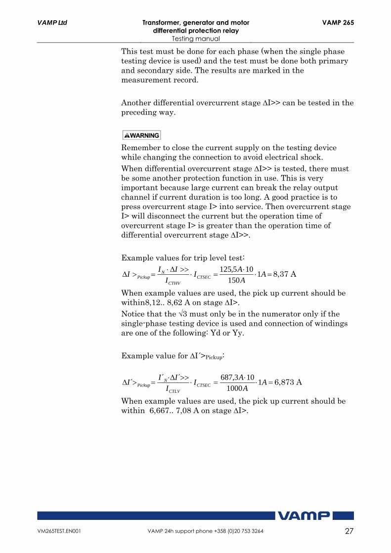
This test must be done for each phase (when the single phase testing device is used) and the test must be done both primary and secondary side. The results are marked in the measurement record. Another differential overcurrent stage ∆I>> can be tested in the preceding way.
Remember to close the current supply on the testing device while changing the connection to avoid electrical shock. When differential overcurrent stage ∆I>> is tested, there must be some another protection function in use. This is very important because large current can break the relay output channel if current duration is too long. A good practice is to press overcurrent stage I> into service. Then overcurrent stage I> will disconnect the current but the operation time of overcurrent stage I> is greater than the operation time of differential overcurrent stage ∆I>>. Example values for trip level test:
AA
AI
I
III CTSEC
CTHV
NPickup 1
150
105,1258,37 A
When example values are used, the pick up current should be within8,12.. 8,62 A on stage ∆I>. Notice that the √3 must only be in the numerator only if the single-phase testing device is used and connection of windings are one of the following: Yd or Yy. Example value for ∆I´>Pickup:
AA
AI
I
III CTSEC
CTLV
NPickup 1
1000
103,687´´´ 6,873 A
When example values are used, the pick up current should be within 6,667.. 7,08 A on stage ∆I>.

VAMP 265 Transformer, generator and motor differential protection relay
Testing manual
VAMP Ltd
28 VAMP 24h support phone +358 (0)20 753 3264 VM265TEST.EN001
5.2.2. Trip level test with three phase testing device When the three phase testing device is in use, the trip level test is done as well as single phase testing device, but now all three current channels can be tested at the same time. First, connect the testing device to the relay´s current inputs IL1, IL2, and IL3. When this test is done, connect the testing device to the relay´s current inputs I´L1, I´L2 and I´L3. If there is possibility to change current angle in the testing device then extreme fault situations can also be tested. The total trip level test can also be made for at least the following connection groups: Yy0, Yy6.
Remember to close the current supply on the testing device while changing the connection to avoid electrical shock.
5.2.3. Trip level test with six-phase testing device The main idea with the six-phase testing device is the same as with the three phase testing device. The difference is that there is a possibility to test the whole differential current protection characteristic. Three of the current channels (current output 1) are connected in the same way as previously. The rest three current channels (e.g current output 2) are connected to the secondary side. Those three current channels will generate load current for the relay. Total trip level test can not be done without load current. The total trip level test needs the bias current to be increased. The currents must be of the same size in both sides. Difference between primary and secondary test currents comes from current transformer scaling. The bias current will be increased at the same time when they ring up currents on both sides. The method gives a possibility to move the test point to the horizontal direction in the characteristic. When this method is used, the test point can be moved on the vertical side for current difference. One way to change the current difference is the possibility to change current angle, because the current on the both sides are almost of the same size. The idea is only to change current angles on the secondary side and increase the current difference in that way. There is also an example of this situation to clarify the situation better. (See Table 5.2.3-1 and Figure 5.2.3-1.) Another method to do the total trip level test is to change primary current so that the current difference is increased and

VAMP Ltd Transformer, generator and motor differential protection relay
Testing manual
VAMP 265
VM265TEST.EN001 VAMP 24h support phone +358 (0)20 753 3264 29
then the relay will trip. The accounting application has been made for this test. First increase currents on both sides so that the currents are of the same value. Then increase the primary current so that the current difference rises and then the relay will trip. The main idea of the test is to establish the following: the relay should trip in test point 1 and the relay should not trip in test point 2. All the test points can be calculated with the calculation program. There is also an example of this situation to clarify the situation better. (See Table 5.2.3-2 and Figure 5.2.3-1). Example for total trip level test: relay nominal current IN = 1 A (same as CT secondary
current) stage ∆I>: pick up level 30% x P/IN, Slope1= 50 %, IBIAS for
start of Slope2= 2 x IN, Slope2= 150%, End of Slope= 5x IN. Protected transformer nominal values: SN= 25000 kVA, UN=115000 V(tap changer position: centre),
U´N=21000 V, IN=125,5 A, I´N=687,3 A CT for HV-side= 150/1A, CT for LV- side= 1000/1A Connection group= YNd11, I0 compensation= YES,
I0´ compensation= NO The settings are used in both methods (method 1 and 2). The total trip level test points are shown in Table 5.2.3-1 and 5.2.3- 2. The method of this test is to change the current angle on the secondary side. There is also Figure 5.2.3-1 which shows calculated test points.

VAMP 265 Transformer, generator and motor differential protection relay
Testing manual
VAMP Ltd
30 VAMP 24h support phone +358 (0)20 753 3264 VM265TEST.EN001
Table 5.2.3-1 Example for trip level test points.(method 1) Test point 1 (Relay should not trip) Test point 5 (Relay should not trip)
IL1 0,84 A 0 deg IL1 2,09 A 0 deg
IL2 0,84 A -120 deg IL2 2,09 A -120 deg
IL3 0,84 A 120 deg IL3 2,09 A 120 deg
I´L1 0,69 A 61 deg I´L1 1,72 A 72 deg
I`L2 0,69 A -59 deg I`L2 1,72 A -48 deg
I`L3 0,69 A 181 deg I`L3 1,72 A 192 deg
Test point 2 (Relay should trip) Test point 6 (Relay should trip)
IL1 0,84 A 0 deg IL1 2,09 A 0 deg
IL2 0,84 A -120 deg IL2 2,09 A -120 deg
IL3 0,84 A 120 deg IL3 2,09 A 120 deg
I´L1 0,69 A 62 deg I´L1 1,72 A 73 deg
I`L2 0,69 A -58 deg I`L2 1,72 A -47 deg
I`L3 0,69 A 182 deg I`L3 1,72 A 193 deg
Test point 3 (Relay should not trip) Test point 7 (Relay should not trip)
IL1 1,51 A 0 deg IL1 3,77 A 0 deg
IL2 1,51 A -120 deg IL2 3,77 A -120 deg
IL3 1,51 A 120 deg IL3 3,77 A 120 deg
I´L1 1,24 A 60 deg I´L1 3,09 A 94 deg
I`L2 1,24 A -60 deg I`L2 3,09 A -26 deg
I`L3 1,24 A 180 deg I`L3 3,09 A 214 deg
Test point 4 (Relay should trip) Test point 8 (Relay should trip)
IL1 1,51 A 0 deg IL1 3,77 A 0 deg
IL2 1,51 A -120 deg IL2 3,77 A -120 deg
IL3 1,51 A 120 deg IL3 3,77 A 120 deg
I´L1 1,24 A 61 deg I´L1 3,09 A 95 deg
I`L2 1,24 A -59 deg I`L2 3,09 A -25 deg
I`L3 1,24 A 181 deg I`L3 3,09 A 215 deg

VAMP Ltd Transformer, generator and motor differential protection relay
Testing manual
VAMP 265
VM265TEST.EN001 VAMP 24h support phone +358 (0)20 753 3264 31
Table 5.2.3-2 Example for trip level test points. (method 2)
Test point 1 (Relay should not trip) Test point 5 (Relay should not trip)
IL1 0,84 A 0 deg IL1 2,09 A 0 deg
IL2 0,84 A -120 deg IL2 2,09 A -120 deg
IL3 0,84 A 120 deg IL3 2,09 A 120 deg
I´L1 0,38 A 30 deg I´L1 1,00 A 30 deg
I`L2 0,38 A -90 deg I`L2 1,00 A -90 deg
I`L3 0,38 A 150 deg I`L3 1,00 A 150 deg
Test point 2 (Relay should trip) Test point 6 (Relay should trip)
IL1 0,84 A 0 deg IL1 2,09 A 0 deg
IL 0,84 A -120 deg IL2 2,09 A -120 deg
IL3 0,84 A 120 deg IL3 2,09 A 120 deg
I´L1 0,37 A 30 deg I´L1 0,99 A 30 deg
I`L2 0,37 A -90 deg I`L2 0,99 A -90 deg
I`L3 0,37 A 150 deg I`L3 0,99 A 150 deg
Test point 3 (Relay should not trip) Test point 7 (Relay should not trip)
IL1 1,51 A 0 deg IL1 3,77 A 0 deg
IL2 1,51 A -120 deg IL2 3,77 A -120 deg
IL3 1,51 A 120 deg IL3 3,77 A 120 deg
I´L1 0,71 A 30 deg I´L1 1,21 A 30 deg
I`L2 0,71 A -90 deg I`L2 1,21 A -90 deg
I`L3 0,71 A 150 deg I`L3 1,21 A 150 deg
Test point 4 (Relay should trip) Test point 8 (Relay should trip)
IL1 1,51 A 0 deg IL1 3,77 A 0 deg
IL2 1,51 A -120 deg IL2 3,77 A -120 deg
IL3 1,51 A 120 deg IL3 3,77 A 120 deg
I´L1 0,70 A 30 deg I´L1 1,20 A 30 deg
I`L2 0,70 A -90 deg I`L2 1,20 A -90 deg
I`L3 0,70 A 150 deg I`L3 1,20 A 150 deg

VAMP 265 Transformer, generator and motor differential protection relay
Testing manual
VAMP Ltd
32 VAMP 24h support phone +358 (0)20 753 3264 VM265TEST.EN001
Figure 5.2.3-1 Testing points for total trip level test.
5.3. Operation time test The methods for the operation time test are the same as in the operation time test of overcurrents stage when single-phase testing device is used. Remember that the operation time is less than the operation time of overcurrent protection stage. Use the network designer values in this testing if possible. If these values are not available, use the following example values or our own example values. Remember to write down the setting values in the measurement record. Test stage ∆I> by supplying 1,5 .. 2 x IN current to each current input and measuring the operation time on output relay by using a timer. When the six-phase testing device is used, the method is the same in the total trip level test, but the test currents needs to be 3,5 x differential current setting. Operation time should be on stage ∆I> and ∆I´>under 60 ms and the operation time should be on stage ∆I>> and ∆I´>> under 40 ms. When the differential current is raised over 3,5x IN then the operation time should be under 50 ms. This test must be done for each phase (when the single-phase testing device is used) and the test must be done on both sides(primary ∆I>,∆I>> and secondary sides ∆I´>,∆I´>> ). The results are marked in the measurement record.
VAMP Ltd Transformer, generator and motor differential protection relay
Testing manual
VAMP 265
VM265TEST.EN001 VAMP 24h support phone +358 (0)20 753 3264 33
6. Earth fault protection stages testing This chapter describes methods of testing the VAMP 265 earth fault protection stages. There are also some pre-calculated values which can be used in the testing.
6.1. Earth fault stage I0> (50N/51N) VAMP 265 has four separate adjustable earth fault stages I0>, I0>>, I0>>> and I0>>>>. The first stage can be configured for definite time (DT) and inverse definite minimum time (IDMT). The function of stages I0>, I0>>, I0>>> and I0>>>> is based on the measured current I01 connected to the input 4 (terminal X1:7-8) and the measured current I02 connected to the input 5 (terminal X1:9-10). This stage is measuring primary earth fault current I01 and secondary earth fault current I02. The setting value of this stage is a per unit (p.u.) value of the residual CT nominal value. If the network designer information is available it is wise to use these values. But this chapter also includes example values which can be used in the testing.
6.1.1. Trip level test Setting values for the relay testing must be marked in the measurement record under, setting values for earth fault stage I0>. The results of the test must be marked in the measurement record site, results for earth fault stage I0> test. Example values for the trip level test: ICToSEC = 5 A
I0SET = 0,05 p.u.
The secondary pick up current will be IINJ = ICToSEC x I0SET = 5 A x 0,05 = 0,25 A The actual pick up current should be within ±5% = 0,237 .. 0,263 A. To find out the actual pick up level, start with current 0,220 A. Then increase current in small steps until the relay picks up. Mark the pick up value in the measurement record.

VAMP 265 Transformer, generator and motor differential protection relay
Testing manual
VAMP Ltd
34 VAMP 24h support phone +358 (0)20 753 3264 VM265TEST.EN001
6.1.2. Operation time test Use the network designer values in this testing if possible. If these values are not available, use the following example values or our own example values. Remember to write down setting values in the measurement record. The specified operation time accuracy is achieved when the current is >200% of the setting value. Example values for operation time test: t = 0,5 s IINJ = 2,05 x 0,25 A = 0,513 A
Other settings same as in preceding trip level test The operation time including the inertia of the output relay should be within ±30 ms: 0,470 .. 0,530 s. Write down the results in the measurement record.

VAMP Ltd Transformer, generator and motor differential protection relay
Testing manual
VAMP 265
VM265TEST.EN001 VAMP 24h support phone +358 (0)20 753 3264 35
7. Thermal protection stage T> (49) The thermal overload function protects the transformer or protective object against thermal overload. The measuring is based on the RMS (Root Mean Square) value of the phase currents from which the heating of the cable to be protected is calculated. The rms values are calculated using harmonic components up to 15th. Thermal stress can be supervised by means of a thermal image. The thermal image can be calculated from the standard heating expression according to IEC 60255-8:
Equation 6.1-1
22
22
)(ln
alarmIkkI
IIt
N
P
, where
t = Operation time τ = Thermal time constant tau ln natural logarithm I = Measured rms phase current IP = preload current
k = Overload factor
k Θ = Ambient temperature factor
IN = The rated current
Equation 6.1-2
22
2
)(ln
NIkkI
It , where
t = Operation time τ = Thermal time constant tau ln natural logarithm I = Measured rms phase current IP = preload current
k = Overload factor
k Θ = Ambient temperature factor
IN = The rated current
The heating time constant (tau [τ]) and the thermal overload current factor (k) corresponding to the maximum thermal load

VAMP 265 Transformer, generator and motor differential protection relay
Testing manual
VAMP Ltd
36 VAMP 24h support phone +358 (0)20 753 3264 VM265TEST.EN001
are settable. The factor k defines the load current value which, when exceeded, results in a thermal trip. The stage is also provided with a settable alarm function, the setting range of which is from 60 to 99% of the thermal trip level. Connection for the thermal overload test is the same as in the overcurrent protection test. When the single-phase testing device is used, first have to connect the secondary injection to input IL1, IL2 or IL3 and then secondary injection have to connect to input I´L1, I´L2 or I´L3. When three-phased testing device is used connect the secondary injection in all three inputs IL1, IL2, IL3. Accordingly connect the secondary injection in all secondary inputs I´L1, I´L2, I´L3 before primary side test. If the network designer information is available it is wise to use these values. But this chapter also includes example values which can be used in testing.
7.1. Trip level and operation time test Setting values for the relay testing must be marked in the measurement record under, setting values for thermal protection stage T>. The results of the test must be marked in the measurement record under, results for thermal protection stage T> test. First set the injected current to zero amps and force the calculated temperature equal to 0,0%. Example values for operation time test: τ = 30 min I = 2,0 A IP = 0 A
k = 1,03 IN = 1,0 A
kΘ = 1,0 alarm = 60 % Time to the 60% alarm at temperature Θalarm according to Equation 8.3.2 will be:
22
22
)6.01103,1(2
02ln30t = 5,199 min = 311,98 s

VAMP Ltd Transformer, generator and motor differential protection relay
Testing manual
VAMP 265
VM265TEST.EN001 VAMP 24h support phone +358 (0)20 753 3264 37
Operation time to 60% alarm should be within ±5%: 296,38.. 327,58 s. Operation time to 100% trip according to Equation 8.3.1 will be:
))1103,1(2
02ln(30 22
22
t = 9,246 min = 554,74 s
Operation time to 100% trip should be within ±5%: 527,00 .. 528,48 s. Mark the calculated alarm time and calculated operation time down to the measurement record. Check that the measured operation time and alarm time is inside the margin.

VAMP 265 Transformer, generator and motor differential protection relay
Testing manual
VAMP Ltd
38 VAMP 24h support phone +358 (0)20 753 3264 VM265TEST.EN001
8. Current unbalance protection (46) Unbalance protection can be tested only with the three-phase testing device! The operation of the unbalance protection is based on the negative phase sequence component I2 related to the positive phase sequence component I1. This is calculated from the phase currents using the method of symmetrical components. The function requires that the measuring inputs are connected correctly so that the rotation direction of the currents is correct.
Equation 7.1-1
1
22I
IK , where
I1 = IL1 + aIL2 + a2IL3
I2 = IL1 + a2 IL2 + aIL3
2
3
2
11201 ja , a phasor rotating constant
8.1. Trip level test Example values for trip level test: ICTSEC = 5,00 A
pick up setting K2 = 10%
operation time t = 1,0 s
Let’s calculate which phase currents for example exceed the pick up setting.
064,31LI 12000,52LI
12000,53LI When these phase currents are used, K2 according to Equation 8.2.1 is 20 %. The actual pick up current IL1 should be within ±0,05 A: 3,59 .. 3,69 A. To find out the actual pick up level start with the

VAMP Ltd Transformer, generator and motor differential protection relay
Testing manual
VAMP 265
VM265TEST.EN001 VAMP 24h support phone +358 (0)20 753 3264 39
current 3,8 A. Then slowly decrease the current until the stage starts.
8.2. Operation time test Both definite time and inverse time characteristics are available. Only the base frequency components of the phase currents are used to calculate the negative sequence value I2. The inverse delay is based on the following equation. Equation 8.2-1
22
2
1
)( KI
IK
t
N
,where
t = operation delay K1 = Delay multiplier I2 = Measured and calculated negative sequence phase
current or fundamental frequency. IN = Rated current K2 = Pick-up setting I2 in p.u. The maximum allowed
degree of unbalance. Example values for the operation time test: K1 = 15 s I2 = 20%= 0.200 xIN
K2 = 5%= 0.05 xIN
22 05.0)1
229.0(
15
t = 300,4 s.
Operation time will be in this example about five minutes. Setting values same as in the preceding trip level test. Decrease the phase current IL1 fast step for example from 1,0 A to 0,75 A. Mark the setting value of operation time and measured operation time to the measurement record.

VAMP 265 Transformer, generator and motor differential protection relay
Testing manual
VAMP Ltd
40 VAMP 24h support phone +358 (0)20 753 3264 VM265TEST.EN001
9. Arc fault protection stage ArcI> (50ARC) The arc fault protection has been implemented with arc sensor inputs and an extremely fast overcurrent function ArcI> or the earth fault functions ArcI0> and ArcI02>. The arc protection function operates when one of the arc sensors detects an arc fault. The arc protection function operates also when the binary input of the arc option card activates and the fast overcurrent stage ArcI> measures an overcurrent, or the earth fault stage ArcI0> or ArcI02> measures an earth fault at the same time. The arc option testing is simple, inject the overcurrent or earth fault current to the relay and at same time give the bright light to the arc sensor. The relay should trip then if the arc option is enabled. Light to the arc sensor must be bright and long enough. A bright flashlight is possibly the best solution for a light source.
9.1. Operation time test Operation time in Arc-option is very fast 20 ms. One method to test the operation time is to give at first bright light to the Arc-sensor. While light is on, give 4x INOM overcurrent or earth fault current to the relay. Measure the operation time as in the testing of overcurrent stages, from the beginning of injection to the trip. Notice that if the light to the arc-sensor is on over 10 seconds, the self supervision of the relay thinks that the arc-sensor is faulty. So when the light is switched on as in the preceding method, you have to inject the overcurrent or earth fault current to the relay input in under 10 seconds. Operation time in arc-option with 4x INOM overcurrent or earth fault current should be under 22 ms. When the arc option has been tested, mark OK to the measurement record.

VAMP Ltd Transformer, generator and motor differential protection relay
Testing manual
VAMP 265
VM265TEST.EN001 VAMP 24h support phone +358 (0)20 753 3264 41
10. Reference information Manufacturer & Service data: VAMP Ltd P.O.Box 810 FIN-65101 Vaasa, Finland Visiting address: Yrittäjänkatu 15 Phone +358 (0)20 753 3200 Fax. +358 (0)20 753 3200 Email: [email protected] URL: http://www.vamp.fi
24h support phone: Tel . +358 (0)20 753 3200 Email: [email protected]

We reserve the rights to changes without prior notice
VAMP Ltd Street address: Yrittäjatu 15 Phone: +358 20 753 3220 Post address: Fax: +358 20 753 3205 P.O Box 810, FIN 65101 Vaasa, Internet: www.vamp.fi Finland Email: [email protected]
VM255TEST.EN001

Measurement record VAMP 265
Page 1/3
Name: Date:
Address Phonnumber:
Relay type: Relay
order code
Serial HW and
number: SW version:
Substation: Cell: Apparatus:
Relay nominal
current: IN> I₀₁> I₀₂>
Technical Relay nominal Auxliary
voltage: voltage:
data Primary current Secondary current
transformer: transformer:
I₀₁ transformer I₀₂ transformer
primary side: secondary side:
Manufacturer: Year of manutacture:
Nominal Connecting
Protected power [kVA] Group:
Hv side Hv side
target nominal voltage Un: nominal voltage U´n:
Nominal primary Nominal secondary
information current IN(calculated): current IN(calculated):
Tap Changer: Centre position
level [%] of tap changer:
Ibias for start up slope2 End of slope
Testing
devices
Visual inspection Wiring inspection CT inspection
ArcI₀₁>/IN ArcI₀₂>/IN t ArcI₀₂> s
ArcI₀₂>Setting
Time
values
I₀>>/IN
I₀>>> Time I₀>>>>
I₀>>
I₀>>>>/IN
t₀> s
ArcI> Time
ArcI>/IN
ArcI`>
t ArcI> s ArcI`>/IN
ArcI₀₁> Time
t ArcI₀₁> s
Time
t ArcI`> s
t₀>> s
t₀>>>> s
Time
Time
I₂>/IN
I`₂>Time
t₂> s
I₀>>>/IN t₀>>> s
I₀>
I₀>/IN
Time
T>/IN
Time
t> s
T>
I´>
I`>/IN
Time
t`₂> s
I₂>
I>>
I>>/IN
Slope2
%
t>> s
Time
dI>>
xIN
dI>
/ /
%
Customer
and
Location
relay
information
dI> 2harm
%
VAMP 265
/// /
Slope1
%
t´> s
I>
I>/IN
x In
Time
t> s
x In
Time
t´´> s
I`>>
I`>>/IN
I`₂>/IN
Time
//

Measurement record VAMP 265
Page 2/3
Time(relay+swichgear)
stages dt´> s (switchgear operating time)
Block
Block
unbalance
stages
Time
L2
ReleasePhase Pick-up Release
L1
T> A T> A
L2
T> sratio
L2
Current L1
stage
L2
Thermal
overload
I₂> A ratioI₂> A t₂> s
Release Release
Release
ratioI´> A
Phase Pick-up
L2
I´> A
L2
Overcurrent
stages
L2
Pick-up ReleasePhase
L1
I´>> A
Release
ratio t´>> s
L1
L2
Time
I>> A ratio t>> s
Release ReleasePick-up
I>> A
t₂>> s
Pick-up ReleaseTime Release Time
ratio
TimePick-up
I´>> A
Release
I´₂> A I´₂> A
Time
t> s
Time
t´> s
Release
I> A I> A ratio
Differential
Overcurrent
L2
L2
Phase Pick-up Release
dI>> A dt>> s
Time
dt´>> sdI´>> A
Phase Pick-up Time Pick-up
L2
L1
L2
dI> A
Release
dI> A
L1
Release
ratio
Release
Results
Pick-up ReleasePick-up TimeTimePhase
dI´> A dI´> A ratio dt´> sdt> s

Measurement record VAMP 265
Page 3/3
Arc
protection
stage
Commissioner: Customer agent:
Clarification of signature: Clarification of signature:
ArcI´> A
Time Pick-up
fault
stages
Phase
I₀>>> A
I₀₂
I₀₁
Pick-upPhase Release Release
t₀>>>> s
ratio
Earth
ratio
I₀₂
ArcI> A
Pick-up
ArcI> s
Time
I₀₂ I₀₂
Pick-up Time
ArcI₀₂> A ArcI₀₂> A
Phase
ArcI₀₂> A
I₀₁I₀₁
L2
L2
L1
ArcI₀₂> A
Phase
ratioI₀>>>> A
Pick-up Time
I₀>>>> A
TimeRelease
ArcI´> s
Release
Time
Pick-up
I₀>>> A ratio t₀> >>s
I₀> A I₀> A
Results
t₀> s
Release Release Release
I₀>> AI₀>> A
I₀₁
Time
t₀>> s
TimePhase Pick-up Release Pick-up
Signature