vacuum ii - cern
TRANSCRIPT

Vacuum II
G. Franchetti
CAS - Bilbao
30/5/2011 G. Franchetti 1

Index
30/5/2011 G. Franchetti 2
Creating Vacuum (continuation)
Measuring Vacuum
Partial Pressure Measurements

Diffusion Ejector pump
30/5/2011 G. Franchetti 3
Lam
inar
flo
w
Inlet
Outlet
Co
ld s
urf
ace
Boiling oil
Schematic of the pump
operating pressure: 10-3 – 10-8 mbar

30/5/2011 G. Franchetti 4
Lam
inar
flo
wInlet
Outlet
Co
ld s
urf
ace
Boiling oil
Pi
Po
Pump principle:
The vacuum gas diffuses into the jet and gets kicked by the oil molecules imprinting a downward momentum
The oil jets produces a skirt which separate the inlet from the outlet

30/5/2011 G. Franchetti 5
Inlet
Outlet
Diffusion
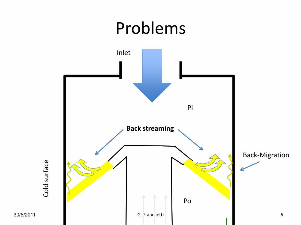
Problems
30/5/2011 G. Franchetti 6
Co
ld s
urf
ace
Pi
Po
Inlet
Back streaming
Back-Migration
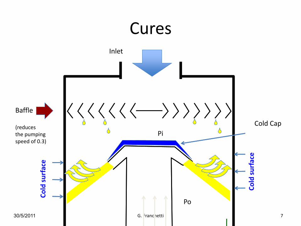
Cures
30/5/2011 G. Franchetti 7
Co
ld s
urf
ace
Pi
Po
Inlet
Baffle
(reduces the pumping speed of 0.3)
Co
ld s
urf
ace
Cold Cap
30/5/2011 G. Franchetti 8
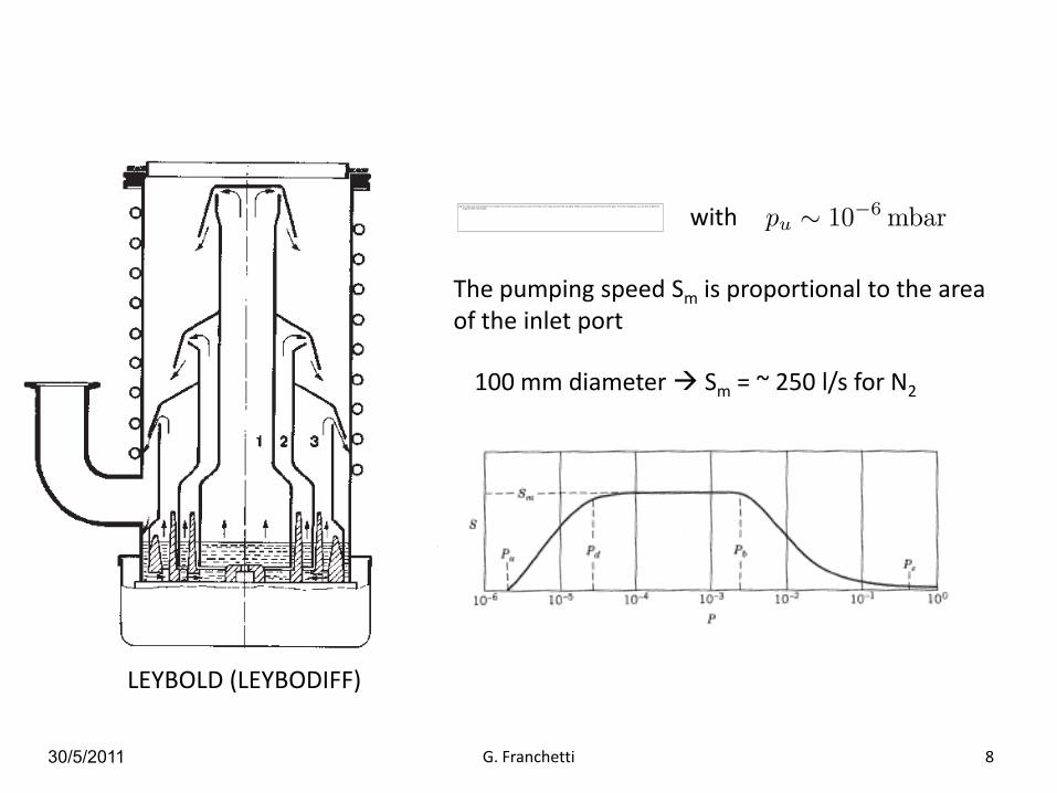
with
The pumping speed Sm is proportional to the area of the inlet port
100 mm diameter Sm = ~ 250 l/s for N2
LEYBOLD (LEYBODIFF)

Capture Vacuum Pumps
30/5/2011 G. Franchetti 9
Getter Pumps(evaporable, non-evaporable)
Sputter ion Pumps
Cryo Pumps
Principle
Capture vacuum pumps are based on the process of capture of vacuum molecules by surfaces

Getter Pumps
30/5/2011 G. Franchetti 10
Solid Bulk
Surface
Gas

11
Heating in vacuum Oxide dissolution -> activation
T = RT
T = Ta
T = RT
NEGs pump most of the gas except rare gases and methane at room temperature
Native oxide layer-> no pumping
Pumping
Getters are materials capable of chemically adsorbing gas molecules. To do so their surface must be clean. For Non-Evaporable Getters a clean surface is obtained by heating to a temperature high enough to dissolve the native oxide layer into the bulk.
Definition of NEG
P. Chiggiato

30/5/2011 G. Franchetti 12
C.Benvenuti, CAS 2007
Sorption Speed and Sorption Capacity

13
energy carrier: noble gas ions
substrate to coat: vacuum chamber
target material: NEG (cathode)
driving force: electrostatic
Choice of the coating technique for thin film: sputtering
Ti
ZrV
NEG composition
The trend in vacuum technology consists in moving the pump progressively closer to the vacuum chamber
wall.
The ultimate step of this process consists of transforming the vacuum chamber from a gas source into a
pump.
One way to do this is by “ex-situ” coating the vacuum chamber with a NEG thin film that will be activated
during the “in situ” bakeout of the vacuum system.

Dipole Coating Facility Quadrupole Coating Facility
30/5/2011 G. Franchetti 14
M.C. Bellachioma (GSI)
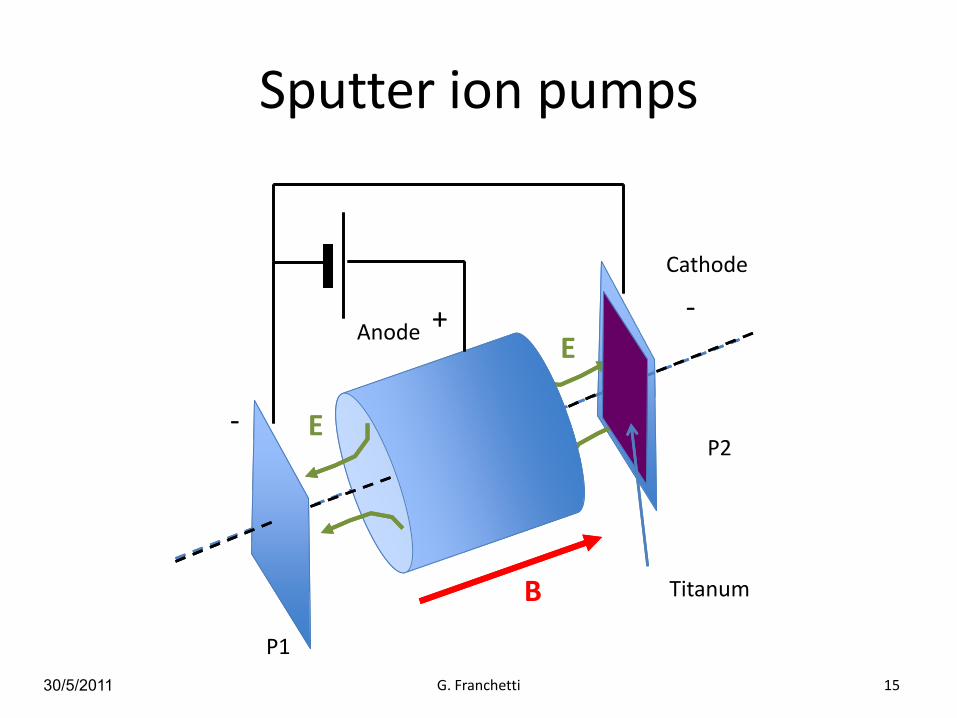
Sputter ion pumps
30/5/2011 G. Franchetti 15
B
-+ -
E
Anode
Cathode
E
P1
P2
Titanum
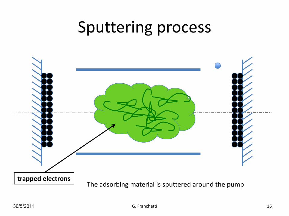
Sputtering process
30/5/2011 G. Franchetti 16
+
The adsorbing material is sputtered around the pumptrapped electrons

30/5/2011 G. Franchetti 17
A glimpse to the complexity
Adsorbed ions
Trapped electronionization process
ion bombardment with sputtering

30/5/2011 G. Franchetti 18
Example of Pumping speed
J.M. Laffterty, Vacuum Science, J. Wiley & Son, 1998

Cryo Pumps
30/5/2011 G. Franchetti 19
m
v1
Stick to the Wall !!
Dispersion forces between molecules and surface are stronger then forces between molecules
Cold Wall

30/5/2011 G. Franchetti 20
cold
Vessel
nw pw
nc pcPump
Pw = pressure warmPc = pressure in the coldIw = flux Vessel PumpIc = flux Pump Vessel
molecules stick to the cold wall
Schematic of a cryo pump

30/5/2011 G. Franchetti 21
Now By using the state equation
In the same way
If no pumping although
Thermal Transpiration
Relation between pressures
30/5/2011 G. Franchetti 22
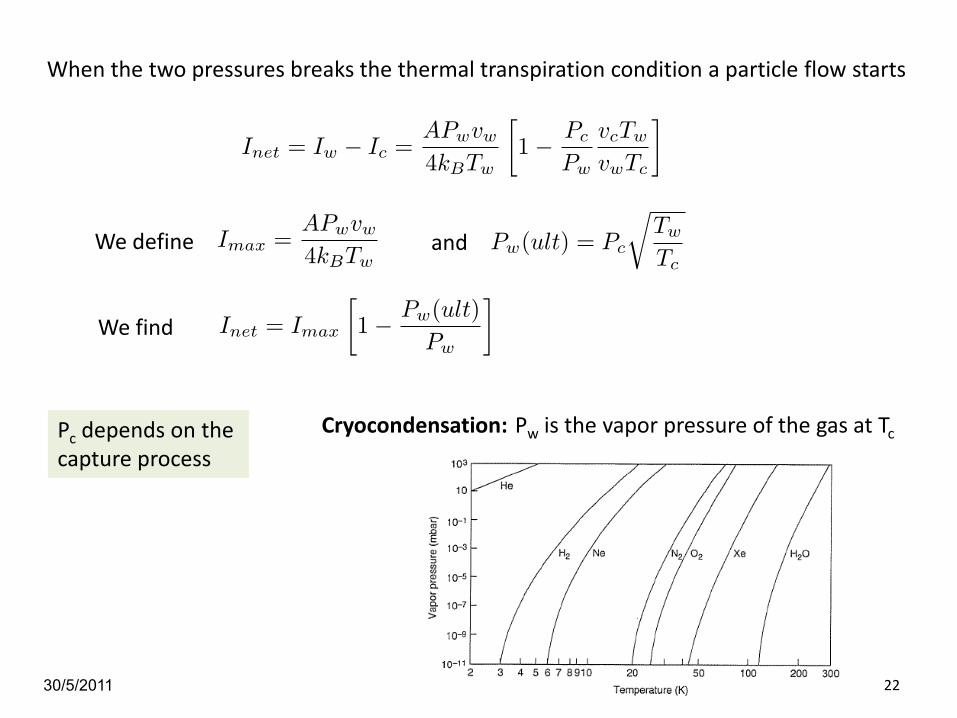
When the two pressures breaks the thermal transpiration condition a particle flow starts
We find
We define and
Pc depends on the capture process
Cryocondensation: Pw is the vapor pressure of the gas at Tc

Summary on Pumps
30/5/2011 G. Franchetti 23
N. Marquardt
Gauges
30/5/2011 G. Franchetti 24
Liquid Manometers
MacLeod Gauges
Viscosity Gauges
Thermal conductivity Gauges
Hot Cathode Gauges
Alpert-Bayard Gauges
Penning Gauges
Liquid Manometers
30/5/2011 G. Franchetti 25
P2
P1 h
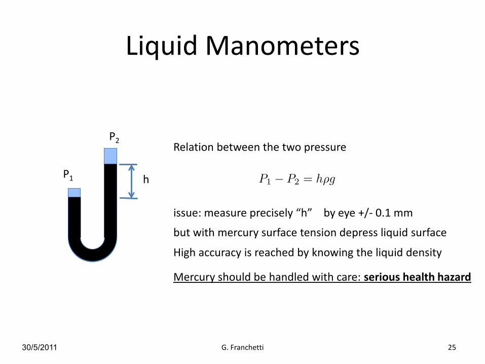
Relation between the two pressure
issue: measure precisely “h” by eye +/- 0.1 mm
High accuracy is reached by knowing the liquid density
but with mercury surface tension depress liquid surface
Mercury should be handled with care: serious health hazard
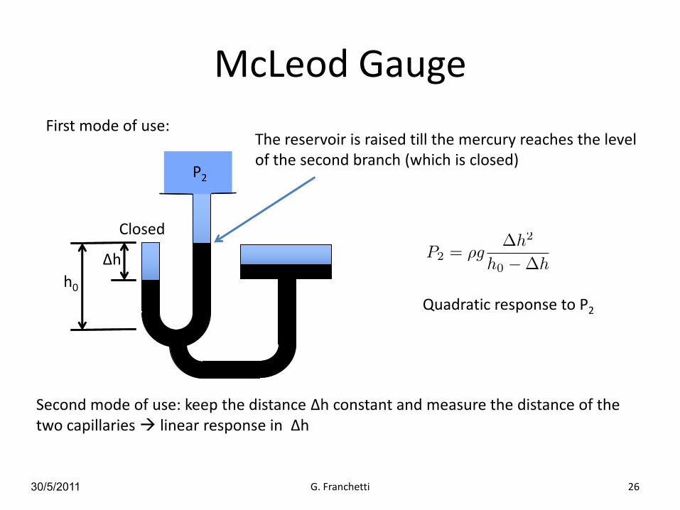
McLeod Gauge
30/5/2011 G. Franchetti 26
Δh
Closed
h0
Quadratic response to P2
First mode of use: The reservoir is raised till the mercury reaches the level of the second branch (which is closed)
P2
Second mode of use: keep the distance Δh constant and measure the distance of the two capillaries linear response in Δh

Viscosity Gauges
30/5/2011 G. Franchetti 27
Gasmolecule
ω
φ
It is based on the principle that gas molecules hitting the sphere surface take away rotational momentum
The angular velocity of the sphere decreases
R
ρ = sphere densityα = coefficient of thermal dilatation
T = temperatureva = thermal velocity

30/5/2011 G. Franchetti 28
(K. Jousten, CAS 2007)
F.J. Redgrave, S.P. Downes, “Some comments on the stability of Spinning Rotor Gauges”, Vacuum, Vol. 38, 839-842

Thermal conductivity Gauges
30/5/2011 G. Franchetti 29
hot wire
A hot wire is cooled by the energy transport operated by the vacuum gas
Accommodation factor
By measuring dE/dt we measure P
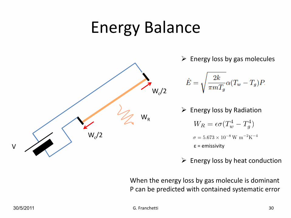
Energy Balance
30/5/2011 G. Franchetti 30
V
Wc/2
Wc/2
WR
Energy loss by gas molecules
Energy loss by Radiation
Energy loss by heat conduction
When the energy loss by gas molecule is dominant P can be predicted with contained systematic error
ε = emissivity

30/5/2011 G. Franchetti 31
The Gauge tube is kept at constant temperature and the current is measured
So that
Through this value E
Pirani Gauge
Example of power dissipated by a Pirani Gauge vs Vacuum pressure
.

Ionization Gauges Principle
30/5/2011 G. Franchetti 32
electrons
accelerating gap
L
V
+

30/5/2011 G. Franchetti 33
V
+
positiveions
new electrons i+ = current proportional
to the ionization rate
E
i-

30/5/2011 G. Franchetti 34
Electrons ionization rate
Sensitivity

Hot Cathode Gauges
30/5/2011 G. Franchetti 35
Grid
Anode
Hot Cathode
30 V
+
180V
+Electric field

Hot Cathode Gauges
30/5/2011 G. Franchetti 36
Grid
Anode
Hot Cathode
30 V
+
180V
+In this region the electrons can ionize vacuum particles
A current between grid and anode is proportional to the vacuum pressure
i+
i+

Limit of use
30/5/2011 G. Franchetti 37
Upper limit: it is roughly the limit of the linear response
Lower limit: X-ray limit
Grid
Anode
new electronX-ray
X-ray
The new electron change the ionization current
P
Pm
X-raylimit
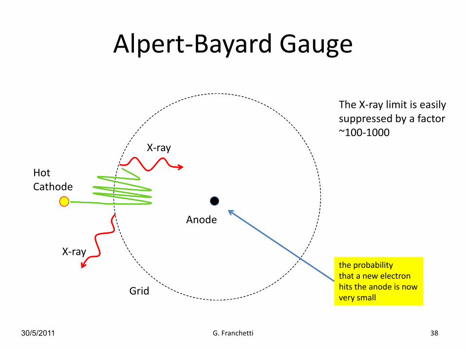
Alpert-Bayard Gauge
30/5/2011 G. Franchetti 38
Grid
Anode
X-ray
X-ray
Hot Cathode
the probability that a new electron hits the anode is now very small
The X-ray limit is easily suppressed by a factor ~100-1000

30/5/2011 G. Franchetti 39
Schematic of the original design (K. Jousten, CAS 2007)

Penning Gauge (cold cathode gauges)
30/5/2011 G. Franchetti 40
B = magnetic field
E = electric field
Electrons motion
anode
cathode

30/5/2011 G. Franchetti 41
+
++ + + + + + +
++ + + + + + +
-
-
-
-
-
-
-
-
-
-
-
-
-
-
-
-
-
-
-
-
One electron is trapped
Under proper condition of (E,B) electrons get trapped in the Penning Gauge

30/5/2011 G. Franchetti 42
+
++ + + + + + +
++ + + + + + +
-
-
-
-
-
-
-
-
-
-
-
-
-
-
-
-
-
-
-
-
One electron is trapped
one vacuumneutral gas enters into the trap

Ionization process
30/5/2011 G. Franchetti 43
Neutral vacuum atom
Electron at ionizationspeed
Before Collision Collision Ionization
Charged vacuum atom
Electron at ionizationspeed
New electron
+-
--

30/5/2011 G. Franchetti 44
+
++ + + + + + +
++ + + + + + +
-
-
-
-
-
-
-
-
-
-
-
-
-
-
-
-
-
-
Ionization
Charged vacuum atom
Electron at ionizationspeed
New electron
+
--
this ion has a too large mass and relatively slow velocity, therefore its motion is dominated by the electric field and not by the magnetic field

30/5/2011 G. Franchetti 45
+
++ + + + + + +
++ + + + + + +
-
-
-
-
-
-
-
-
-
-
-
-
-
-
-
-
-
-
Ionization Charged vacuum atom
New electron
+
--
Motion of stripped ion
30/5/2011 G. Franchetti 46
++ + + + + + +
++ + + + + + +
-
-
-
-
-
-
-
-
-
-
-
-
-
-
-
-
-
-
+
+
+
+
+
+
+
+
+
+
+
+
+
+
+
+
-
- -
-
-
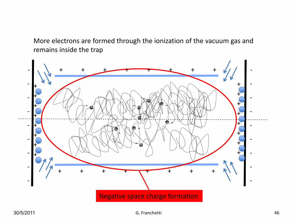
Negative space charge formation
More electrons are formed through the ionization of the vacuum gas and remains inside the trap
30/5/2011 G. Franchetti 47
++ + + + + + +
++ + + + + + +
-
-
-
-
-
-
-
-
-
-
-
-
-
-
-
-
-
-
+
+
+
+
+
+
+
+
+
+
+
+
+
+
+
+
-
- -
-
-
-
-
-
--
-
--
-
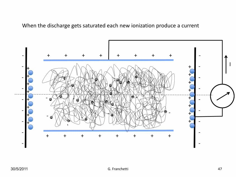
When the discharge gets saturated each new ionization produce a current
I

30/5/2011 G. Franchetti 48
The time necessary for the discharge formation depends upon the level of the vacuum
lower pressure longer time of formation
Sensitivity of a SIP (the same as for the Penning Gauge).
J.M. Lafferty, Vacuum Science,p. 322

Summary on Gauges
30/5/2011 G. Franchetti 49
N. Marquardt
Partial Pressure Measurements
30/5/2011 G. Franchetti 50
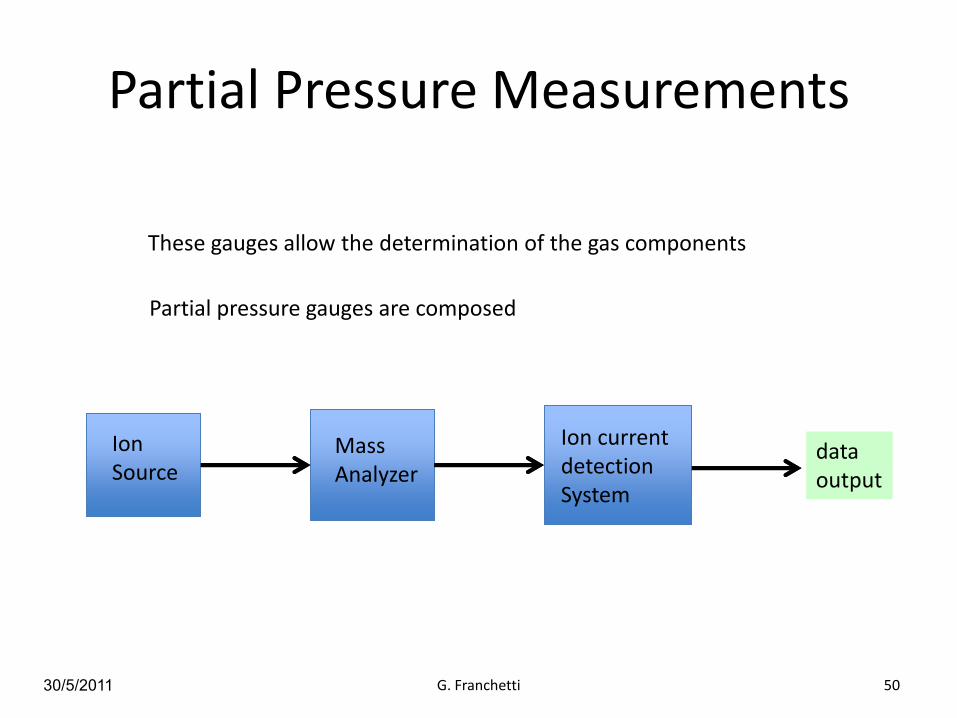
These gauges allow the determination of the gas components
Partial pressure gauges are composed
Ion Source
MassAnalyzer
Ion currentdetection System
dataoutput

Ion Sources
30/5/2011 G. Franchetti 51
Vacuum gas is ionized via electron-impact
the rate of production of ions is proportional to each ion species
Electron-impact ionization process
ev
inelastic scattering: kinetic energy transfer from the electron to the molecule
me
M
Before Impact After impact
e
vme
M+
e
v
me

30/5/2011 G. Franchetti 52
The minimum energy to ionize M is called “appearance potential”
Electronenergy(eV)
15IP = 15 eV M+ + e-
At the appearance potential the production rate is low
appearance potential
A. von Engel, Ionized Gases, AVS Classics Ser., p. 63. AIP Press, 1994

Ion source
30/5/2011 G. Franchetti 53
ionizationregionelectrons
source
acceleration gap
Vf
Vg
electrons
ions
ion collector
+
+
+
E
E
Vc
Open sourceBayard-Alpert gauge
Vg < Vc

30/5/2011 G. Franchetti 54
+
+
+
+
+
+
+
+
A schematic
F = ion transmission factorMass analyzer
Ion Detection

Ion Detection
30/5/2011 G. Franchetti 55
Faraday Cup Secondary electron Multiplier (SEM)
Idea: an ion enters into the tube, and due to the potential is accelerated to the walls. At each collision new electrons are produced in an avalanche process
# electrons output
# ion inputG =
Gain
L
d V0 = applied voltage
V = initial energy of the electron
K = δ Vc
where
δ = secondary emission coefficientVc = collision energyJ.Adams, B.W. Manley IEEE Transactions on Nuclear Science, vol. 13, issue 3, 1966. p. 88

Mass Analyzers
30/5/2011 G. Franchetti 56
Quadrupolar mass spectrometer
x
y s
Ion equation of motion
U, V constant
r0
define:

30/5/2011 G. Franchetti 57
By rescaling of the coordinates the equation of motion becomes
Mathieu Equation
Stability of motion
horizontal vertical
q=0, a>0 unstable stable
q=0, a<0 stable unstable
The presence of the term q, changes the stability condition
Development of stable motion
The ion motion can be stable or unstable
Stable or unstable motion is referred to a channel which is infinitely long, but typically a length correspondent to 100 linear oscillation is considered enough
Example:For N2 at Ek = 10 eV vs = 8301 m/s
For a length of L = 100 mm 100 rf oscillation f = 8.3 MHz
typically f ~ 2 MHz

30/5/2011 G. Franchetti 58
5 10 15
0
5
10
5
10
a
q
Stable in y
5 10 150
5
10
5
10
a
q
Stable in x
Stability Chart of Mathieu equation

30/5/2011 G. Franchetti 59
5 10 15
0
5
10
5
10
a
q
a
Stability region in both planes
q
a
q0=0.706 a0=0.237

30/5/2011 G. Franchetti 60
Stability region in both planes
q
a
(0.706; 0.237)
Given a certain species of mass M1 there are two values U1, V1 so that q=q0 and a=a0
By varying V and keeping the ratio V/U constant, the tip of the stability is crossed and a current is measured at V=V1
V
i+
30/5/2011 G. Franchetti 61
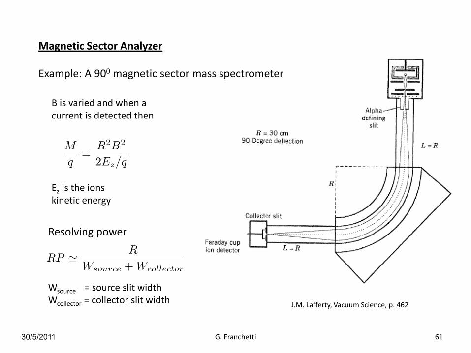
Magnetic Sector Analyzer
Example: A 900 magnetic sector mass spectrometer
B is varied and when a current is detected then
Ez is the ions kinetic energy
Resolving power
Wsource = source slit widthWcollector = collector slit width
J.M. Lafferty, Vacuum Science, p. 462
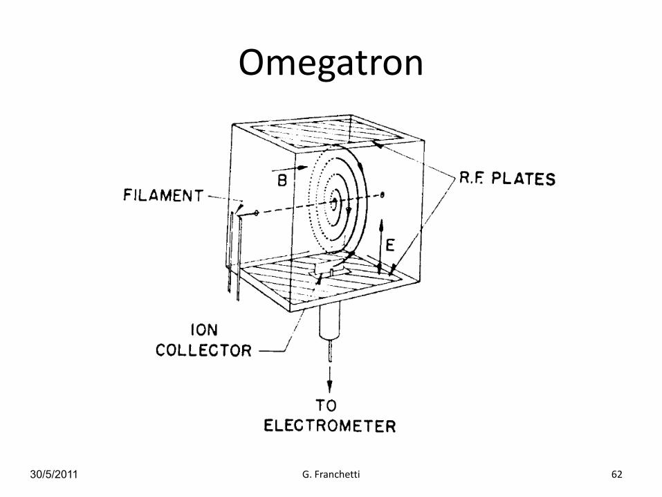
Omegatron
30/5/2011 G. Franchetti 62

30/5/2011 G. Franchetti 63
The revolution time is independent from ion energy
If the frequency of the RF is 1/τa resonant process takes place and particle spiral out
collector
B
E
Resolving power

Conclusion
30/5/2011 G. Franchetti 64
Creating and controlling vacuum will always be a relevant part of any accelerator new development.
These two lectures provides an introduction to the topic, which is very extensive: further reading material is reported in the following bibliography
THANK YOU FOR YOUR ATTENTION

30/5/2011 G. Franchetti 65
Kinetic theory and entropy ,C.H. Collie, Longam Group, 1982
Thermal Physics, Charles Kittel, (John Wiley and Sons, 1969).
Basic Vacuum Technology (2nd Edn), A Chambers, R K Fitch, B S Halliday, IoPPublishing, 1998, ISBN 0-7503-0495-2
Modern Vacuum Physics, A Chambers, Chapman & Hall/CRC, 2004, ISBN 0-8493-2438-6
The Physical Basis of Ultrahigh Vacuum, P. A. Redhead, J. P. Hobson, E. V. Kornelsen, AIP, 1993, ISBN 1-56396-122-9
Foundation of Vacuum Science, J.M. Lafferty, Wiley & Sons, 1998
Vacuum in accelerators, CERN Accelerator School, CERN-2007-003 11 June 2007
Vacuum technology, CERN Accelerator School, CERN 99-05 1999
Acknowledgements: Maria Cristina Bellachioma