vacuum system - cern
TRANSCRIPT

VACUUM
CAS, Small Accelerator course, Zeegse, Netherlands, 24 May 2 June 2005
Vacuum System Oswald Gröbner
1) Introduction and some basics
2) Vacuum pumps and gauges
3) Gas desorption
4) Components and materials Oswald Gröbner, Retired from CERN Vacuum Group. Present Address: Schmiedgasse 5, Innsbruck, AT-6020, Austria e-mail: [email protected], [email protected]
Oswald Gröbner

VACUUM
Literature
Books The Physical Basis of Ultrahigh Vacuum, P.A. Redhead, J.P. Hobson, E.V. Kornelsen, American Vacuum
Society Classics, American Institute of Physics, 1993
Foundations of Vacuum Science and Technology, Ed. J.M. Lafferty, John Wiley & Sons, 1998
Handbook of Accelerator Physics and Engineering, A. W. Chao, M. Tigner, World Scientific, 1998
CAS CERN Accelerator School : Vacuum Technology, Ed. : S. Turner. CERN 99-05, 19 August 1999
Handbuch Vakuumtechnik, M. Wutz et. al, Vieweg, Braunschweig/Wiesbaden, 2000
Journals: VACUUM
Journal of Vacuum Science and Technology (A)
Nuclear Instruments and Methods (Section A)
Oswald Gröbner

VACUUM
Pressure and Molecular Density
Ideal gas law: P V = NNo
R T
P pressure, V volume, T temperature N number of molecules R gas constant = 8.31 kJ kmol-1 K-1, No = 6.02 1026 molecules kmol-1
Molecular density n = NV
Pressure : P = n k T Boltzmann constant k = 1.38 10-23 J/K
Note : R = No k Note: In nearly all cases, it is the gas density rather than the pressure which matters. Units :
Pressure : Pa (N/m2), mbar = 100 Pa, Torr = 133 Pa Gas load : Pa m3 = 7.5 Torr l, mbar l ~ 2.4 1019 molecules at RT Specific outgassing rate : Gas release from the walls Pa m3/s/m2 ~ 7.5 10-4 Torr l/s/cm2
Leak rate : Pa m3/s or W, mbar l/s or Torr l/s
Oswald Gröbner
VACUUM
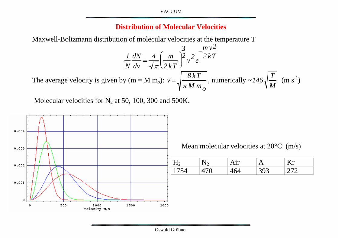
Distribution of Molecular Velocities
Maxwell-Boltzmann distribution of molecular velocities at the temperature T
1N
dNdv
= 4π
m2 kT
⎛
⎝ ⎜ ⎞
⎠ ⎟
32
v2e−m v2
2 kT
The average velocity is given by (m = M mo): v = 8 kTπ M mo
, numerically ~146 TM
(m s-1)
Molecular velocities for N2 at 50, 100, 300 and 500K.
Mean molecular velocities at 20°C (m/s)
H2 N2 Air A Kr1754 470 464 393 272
Oswald Gröbner

VACUUM
Mean Kinetic Energy
The kinetic energy : Ekin
= 12
m v 2 = 12
M mo8kT
π M mo
⎛
⎝ ⎜
⎞
⎠ ⎟ =
4π
kT
M molecular weight, mo = 1.66 10-27 kg does not depend on the molecular mass, M, but only on temperature T. In thermal equilibrium heavy molecules move sufficiently slowly and light molecules move sufficiently fast to carry on average the same kinetic energy.
Total and Partial Pressures
For each gas component n1, n2, n3,… the contribution to the total pressure :Pi = ni kT
The total pressure is the sum of all partial pressures: P = Pii∑ = k T nii
∑
Partial pressures for atmospheric air Gas % Pi (Pa)
N2 78.1 7.9 104
O2 20.5 2.8 103
Ar 0.93 1.2 102
CO2 0.0033 4.4Ne 1.8 10-3 2.4 10-1
He 5.2 10-4 7 10-2
Oswald Gröbner

VACUUM
Wall collisions
Rate of molecular impacts on the walls ν = 14
n v
Mean Free Path
2D
D v
D
D
l = 1
2 π D2 n
D molecular diameter (~3 10-8 m)
Distance traversed per second v Molecule collides with other molecules contained within a cylinder of radius D. Number of collisions: Z ≈ π D2v n
Mean free path l = v Z
= 1
2 π D2 n
It also follows that n l ∝ P l ≈ const. For air n l ≈ const is ~ 2.5 1014 m-2 for N2 at 20 °C and 1 Pa -> l ~ 9 mm
Oswald Gröbner

VACUUM
Molecular Flow Conditions
Knudsen relation: gas flow Q ∝ ∆P applies if the mean free path >> relevant dimensions of system Molecular flow conductance c =
43
v HA2 dl
0
L∫
(m3/s)
L length of the element (L >> transverse dimensions). H perimeter, A cross section of the element.
The conductance is proportional to the mean molecular velocity, i.e. to TM .
A cylindrical duct with uniform section and radius r : c= 43 v r3
L⎛
⎝
⎜ ⎜
⎞
⎠ ⎟ ⎟ ~ 306 ⋅ r3
L⎛
⎝
⎜ ⎜
⎞
⎠ ⎟ ⎟
TM .
An orifice (pumping orifice, L~0) : c= 14 v A ~ 36.5 ⋅A T
M .
Conductance of elements in series or in parallel add the same as for electric circuits 1Series : c = 1
c1
+ 1c2
and parallel: c = c1 +c2
For complicated geometries it is often necessary to use Monte Carlo calculations for the molecular flow.
Oswald Gröbner
VACUUM
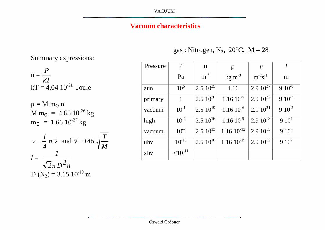
Vacuum characteristics
gas : Nitrogen, N2, 20°C, M = 28 Summary expressions: Pressure P
Pa
n
m-3
ρ
kg m-3
ν
m-2s-1
l
m
atm 105 2.5 1025 1.16 2.9 1027 9 10-8
primary
vacuum
1
10-1
2.5 1020
2.5 1019
1.16 10-5
1.16 10-6
2.9 1022
2.9 1021
9 10-3
9 10-2
high
vacuum
10-4
10-7
2.5 1016
2.5 1013
1.16 10-9
1.16 10-12
2.9 1018
2.9 1015
9 101
9 104
uhv 10-10 2.5 1010 1.16 10-15 2.9 1012 9 107
xhv <10-11
n = PkT
kT = 4.04 10-21 Joule ρ = M mo n M mo = 4.65 10-26 kg mo = 1.66 10-27 kg
ν = 14
n v and v = 146 TM
l = 1
2π D2n
D (N2) = 3.15 10-10 m
Oswald Gröbner

VACUUM
Thermal Conductivity
Thermal conductivity of a gas is independent of the pressure when the pressure is well above the molecular flow regime. In the transition regime, the heat transfer is proportional to the pressure and to the temperature difference. Principle of pressure measurement with a Pirani gauge.
10-3 Torr < P < 10 Torr
At very low pressures, the heat transfer by conduction is is negligible : vacuum for thermal insulation in cryogenics.
LHC Cryodipole
Oswald Gröbner
VACUUM
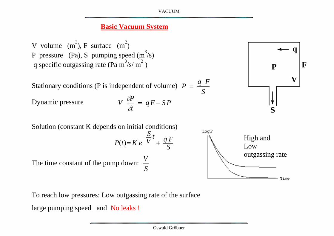
Basic Vacuum System V volume (m3), F surface (m2) P pressure (Pa), S pumping speed (m3/s) q specific outgassing rate (Pa m3/s/ m2 ) Stationary conditions (P is independent of volume)
P = q F
S
S
V
High and Low outgassing rate
FP
q
Dynamic pressure V ∂P∂t
= q F − S P
Solution (constant K depends on initial conditions)
P(t)= K e
− SV
t+ q F
S
The time constant of the pump down: VS
To reach low pressures: Low outgassing rate of the surface
large pumping speed and No leaks !
Oswald Gröbner

VACUUM
Rotary Pumps
To Atmosphere
From Vacuum
Single stage and double stage pumps Oil sealed moving pistons Typical end pressure : 10-2 to ~10-3 mbar Typical pumping speed : 4 to ~ 40 m3/h Adequate for systems with small volume Filter for oil vapour is required. Dry pumps, without oil, are available but rather expensive!
Oswald Gröbner
VACUUM
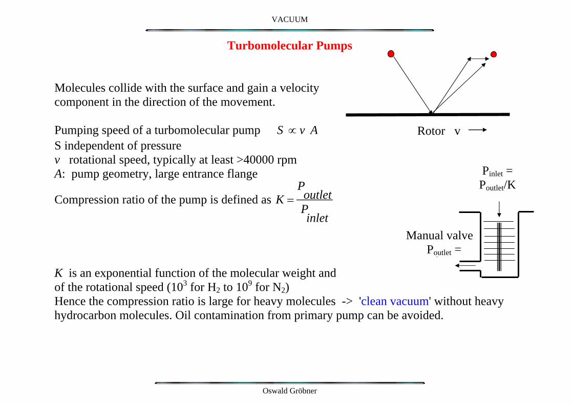
Turbomolecular Pumps
Rotor v
Molecules collide with the surface and gain a velocity component in the direction of the movement. Pumping speed of a turbomolecular pump S ∝ v A S independent of pressure v rotational speed, typically at least >40000 rpm
Pinlet = Poutlet/K
A: pump geometry, large entrance flange
Compression ratio of the pump is defined as K =PoutletPinlet
Manual valvePoutlet =
3
K is an exponential function of the molecular weight and of the rotational speed (103 for H2 to 109 for N2) Hence the compression ratio is large for heavy molecules -> 'clean vacuum' without heavy hydrocarbon molecules. Oil contamination from primary pump can be avoided.
Oswald Gröbner

VACUUM
Mobile pumping unit for LEP vacuum system External pumps required for initial pump down only.
Manual valveDisconnect flange
Automatic valve
Pressure gauges
Separation valve
Turbo pump
Rotary pump
Leak detector
Venting
Venting
Oil mist filter To atmosphere
Beam line
During operation of the accelerator, the manual separation valve is closed. The mobile pumps can be removed from the tunnel for maintenance and to avoid radiation damage.
Oswald Gröbner

VACUUM
Sputter-Ion-Pump
Configuration of a parallel electric and magnetic field produces a self-maintained discharge plasma. -> Penning configuration Ionised residual gas molecules are accelerated towards the Ti cathode and ‘trapped’ and removed from the gas phase. Sputtering of Ti from cathode produces a clean gettering film. In a particle accelerator, the magnetic field is provided by bending magnets. --> integrated, linear ion-pumps. To increase the pumping speed, arrays of cells are used
Oswald Gröbner
VACUUM
Pumping action
Gettering -> chemisorption of active species H2, CO, N2, O2, CO2 Diffusion of H2 into the Ti- cathode (re-diffusion!) Cracking of inert hydrocarbons into C, H, O which can be pumped (chemisorbed) separately Nobel gases: energetic ions of He, Ne, A by implantation into the cathode: “ion burial” of energetic ions. -> Argon instability after pumping of air. To increase the discharge intensity and thus the pumping speed it is desirable to increase the sputtering rate of the titanium cathode
Triode Sputter-Ion pump with grazing incidence of ions on a grid cathode Note: Molecules are not removed from the vacuum system. Important memory effect of previously pumped gas (Argon).
Oswald Gröbner
VACUUM
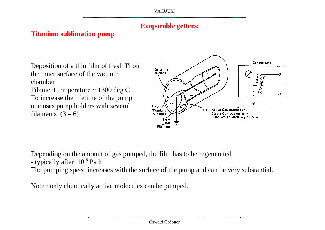
Evaporable getters: Titanium sublimation pump
Deposition of a thin film of fresh Ti on the inner surface of the vacuum chamber Filament temperature ~ 1300 deg C To increase the lifetime of the pump one uses pump holders with several filaments (3 – 6) Depending on the amount of gas pumped, the film has to be regenerated - typically after 10-6 Pa h The pumping speed increases with the surface of the pump and can be very substantial. Note : only chemically active molecules can be pumped.
Oswald Gröbner
VACUUM
Non-Evaporable Getters or Bulk getters (NEG) : Getter material ( e.g. Ti, Zr, V) produced in the form of an alloy e.g. with Al and used as a bulk material. For LEP : metal ribbon coated with a thin layer of getter powder has been used. Clean, active gettering surface is produced by heating under vacuum. Gas adsorbed on the surface diffuses into the bulk and a ‘clean’ surface can be obtained. Activation requires heating from 350 °C up to 700°C for one hour depending on the specific getter. A new development consisting of a combination of evaporable getters and of bulk getters is under development at CERN -> sputter deposited getter films (few µm only) coated directly onto the inner surface of vacuum chambers. First use in insertion chambers (ESRF) and for LHC vacuum (CERN).
Note: Getters have a limited total pumping capacity and a memory effect of the gas previously pumped.
Getters pump only chemically active gas i.e. nobel gases and hydrocarbons (methane, …) are NOT pumped. Combination with ion pumps is required.
Oswald Gröbner
VACUUM
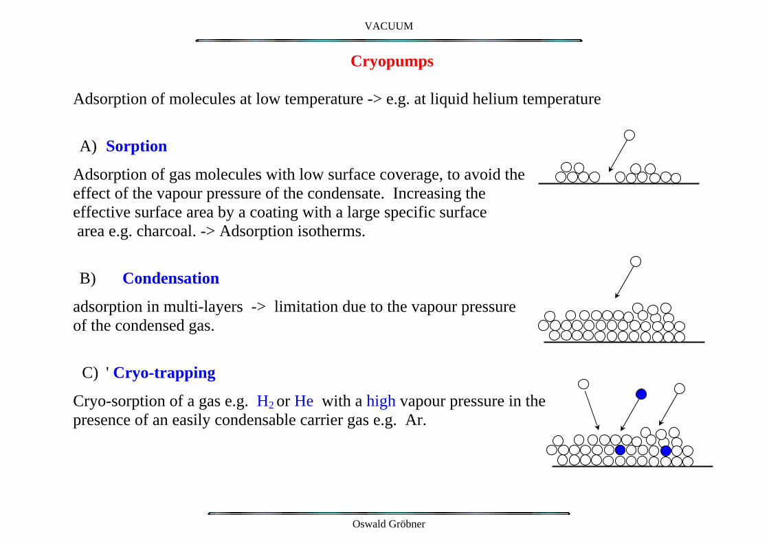
Cryopumps
Adsorption of molecules at low temperature -> e.g. at liquid helium temperature
A) Sorption
Adsorption of gas molecules with low surface coverage, to avoid the effect of the vapour pressure of the condensate. Increasing the effective surface area by a coating with a large specific surface area e.g. charcoal. -> Adsorption isotherms.
B) Condensation
adsorption in multi-layers -> limitation due to the vapour pressure of the condensed gas.
C) ' Cryo-trapping
Cryo-sorption of a gas e.g. H2 or He with a high vapour pressure in the presence of an easily condensable carrier gas e.g. Ar.
Oswald Gröbner
VACUUM
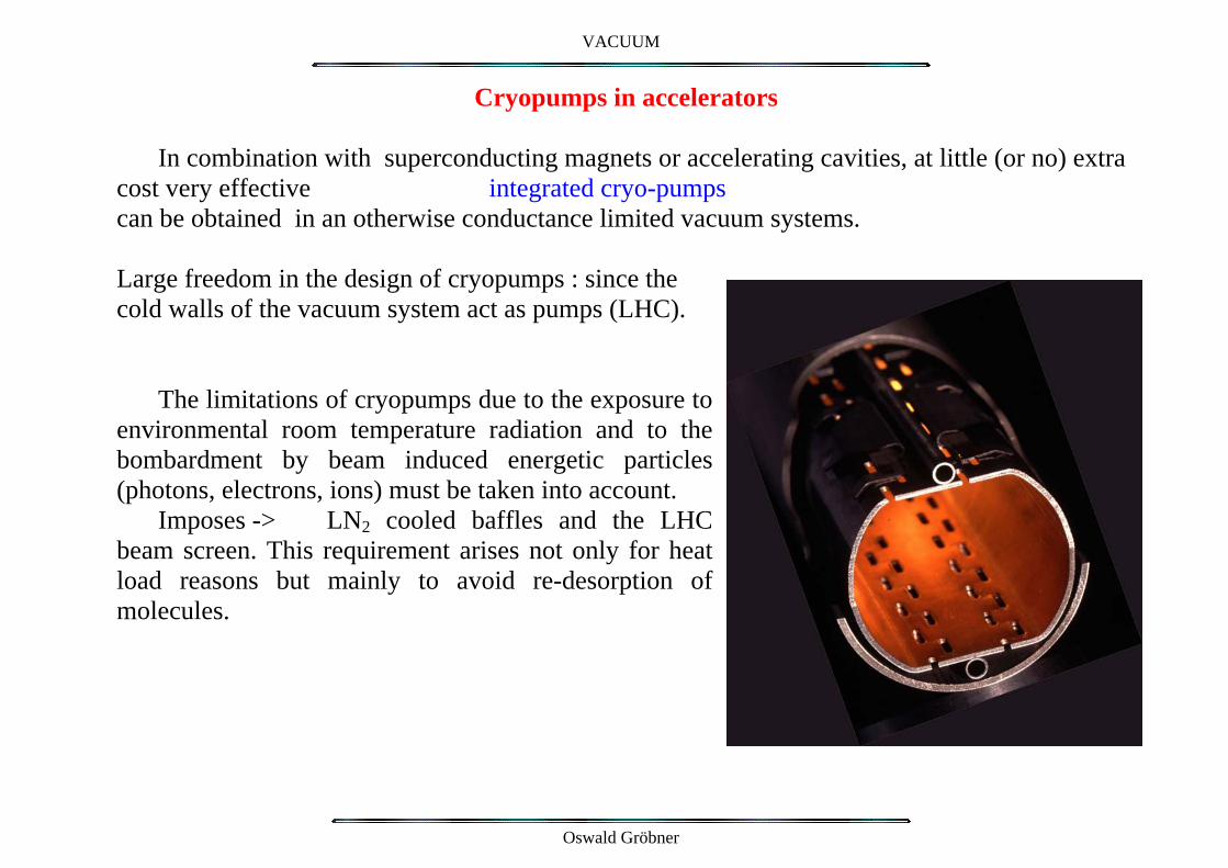
Cryopumps in accelerators In combination with superconducting magnets or accelerating cavities, at little (or no) extra
cost very effective integrated cryo-pumps can be obtained in an otherwise conductance limited vacuum systems. Large freedom in the design of cryopumps : since the cold walls of the vacuum system act as pumps (LHC).
The limitations of cryopumps due to the exposure to environmental room temperature radiation and to the bombardment by beam induced energetic particles (photons, electrons, ions) must be taken into account.
Imposes -> LN2 cooled baffles and the LHC beam screen. This requirement arises not only for heat load reasons but mainly to avoid re-desorption of molecules.
Oswald Gröbner
VACUUM
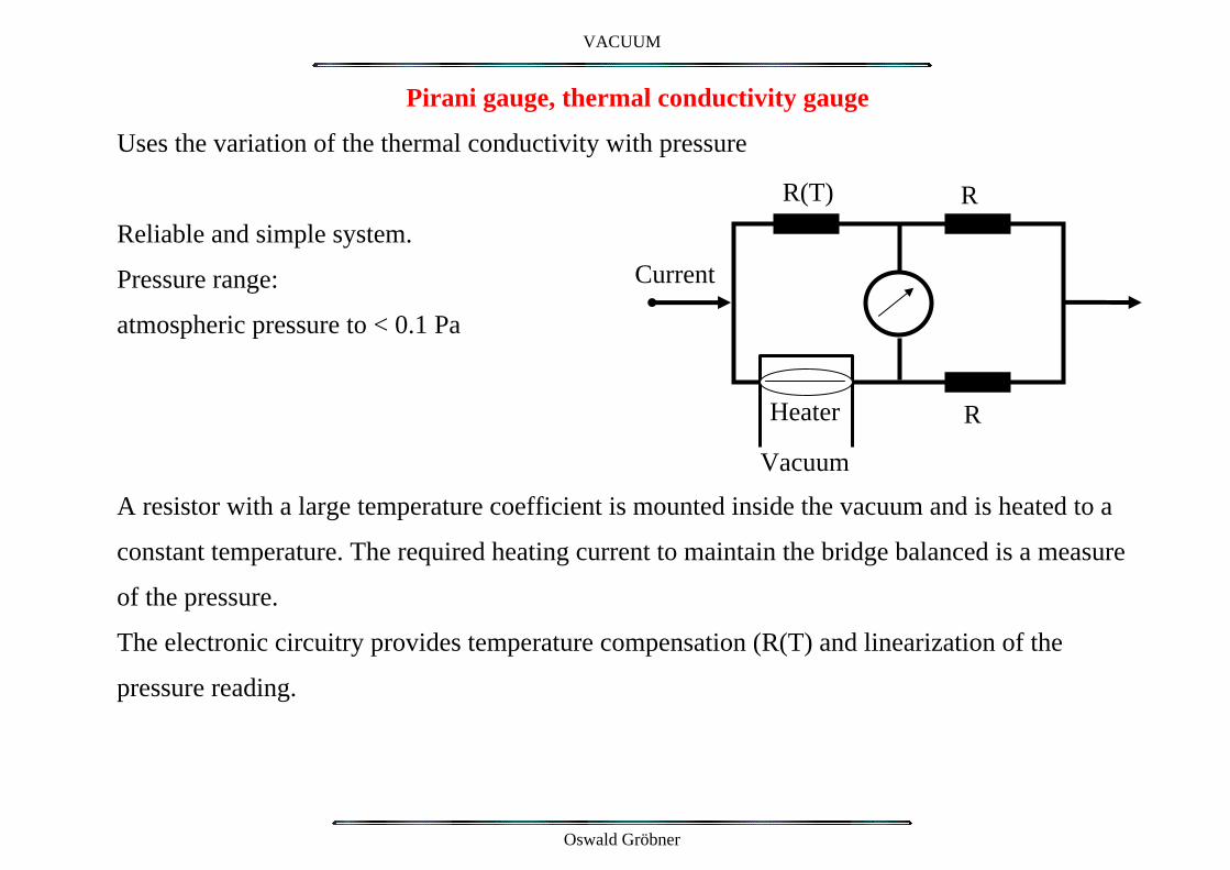
Pirani gauge, thermal conductivity gauge
Uses the variation of the thermal conductivity with pressure
Heater Vacuum
Current
R
RR(T) Reliable and simple system.
Pressure range:
atmospheric pressure to < 0.1 Pa
A resistor with a large temperature coefficient is mounted inside the vacuum and is heated to a
constant temperature. The required heating current to maintain the bridge balanced is a measure
of the pressure.
The electronic circuitry provides temperature compensation (R(T) and linearization of the
pressure reading.
Oswald Gröbner

VACUUM
Cold Cathode Ionisation Gauge, Penning Gauge
Based on the operating principle of an ion pump: Vacuum
Discharge current is ~proportional to pressure. Ground + 1kV
Useful pressure range: 10-2 to 10-7 Pa Ions Electrons
At high pressure the discharge is unstable (arcing)
At low pressure the discharge extinguishes -> zero
pressure reading
SNLeakage current in the cables and in the gauge can
simulate a higher pressure.
Contamination of the gauge may change the calibration.
Extended operation at high pressure will ‘contaminate’ the gauge -> required demounting and
cleaning of the gauge.
Improved version for low pressures on the market: Inverted magnetron gauge
Oswald Gröbner

VACUUM
Hot Filament ionization Gauge
Operating principle : Residual gas molecules are ionized by the electrons emitted from a hot filament. Ions are collected by a "collector electrode". This ion current is proportional to the gas density, n, and hence to the pressure, P. The ionization probability Pi (number of ion–electron pairs produced per m and per Pa) depends on the type of molecule and on the kinetic energy of the electrons. Ion collector current : I+ = Ie Pi L P Where : Ie emission current of the filament
L path length of the electrons P pressure
Oswald Gröbner

VACUUM
Gauge Sensitivity
[Pa-1] S = Pi L
Obtained by calibration with a known pressure (N2) Nitrogen equivalent pressure N2.
To measure a pressure for another gas, the relative gauge sensitivity for this particular gas with respect to nitrogen must be known.
Si/SN2 must be known for different gas species.
For H2, one finds typically SH2/SN2 ~ 0.38
Oswald Gröbner

VACUUM
Helium leak detector
Mass spectrometer tuned to Helium, which is commonly used as the ‘tracer gas’. Purpose of the LN2 filled cold trap is to remove oil vapours of the diffusion pump as well as water vapour from the spectrometer cell
Oswald Gröbner
VACUUM
Leaks and leak detection Common leaks to atmospheric pressure: Gaskets
Porosities in the materials Cracks and porosities in welds Virtual leaks: are not found by a conventional leak check Porosities, a dead volume enclosed inside the system Example of a virtual leak: The volume enclosed by a bolt in a threaded hole. Solution: bolts have to be drilled with a central hole or a separate hole must be drilled to pump the dead volume. In a large vacuum system, leak checks of all sub-components are mandatory. A global leak check after complete assembly should only concern those joints, which have been made during the final installation phase in the accelerator.
Oswald Gröbner
VACUUM
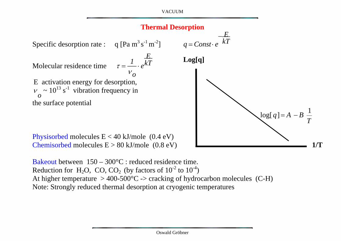
Thermal Desorption
Specific desorption rate : q [Pa m3 s-1 m-2] q = Const ⋅ e− E
kT
Molecular residence time τ = 1ν o
⋅ eEkT
Log[q]
E activation energy for desorption, ν
o ~ 1013 s-1 vibration frequency in
the surface potential
log[ q] = A − B 1T
Physisorbed molecules E < 40 kJ/mole (0.4 eV)
1/T Chemisorbed molecules E > 80 kJ/mole (0.8 eV) Bakeout between 150 – 300°C : reduced residence time. Reduction for H2O, CO, CO2 (by factors of 10-2 to 10-4) At higher temperature > 400-500°C -> cracking of hydrocarbon molecules (C-H) Note: Strongly reduced thermal desorption at cryogenic temperatures
Oswald Gröbner
VACUUM
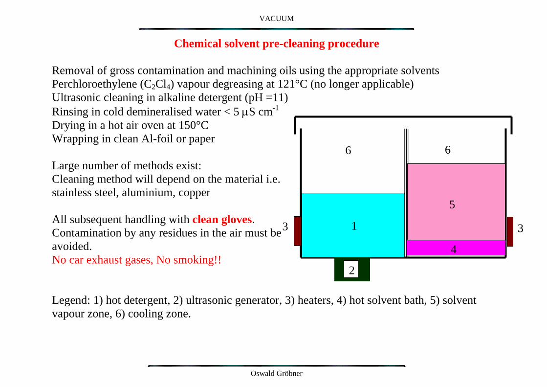
Chemical solvent pre-cleaning procedure
Removal of gross contamination and machining oils using the appropriate solvents Perchloroethylene (C2Cl4) vapour degreasing at 121°C (no longer applicable) Ultrasonic cleaning in alkaline detergent (pH =11) Rinsing in cold demineralised water < 5 µS cm-1
Drying in a hot air oven at 150°C Wrapping in clean Al-foil or paper
66 Large number of methods exist: Cleaning method will depend on the material i.e. stainless steel, aluminium, copper
5 All subsequent handling with clean gloves. 13 3 Contamination by any residues in the air must be avoided. 4No car exhaust gases, No smoking!!
2 Legend: 1) hot detergent, 2) ultrasonic generator, 3) heaters, 4) hot solvent bath, 5) solvent vapour zone, 6) cooling zone.
Oswald Gröbner

VACUUM
Glow-Discharge Cleaning
Vacuum chamber
+ 300V
Ar+
Discharge gas
Electrode Cleaning of the surface by energetic ion bombardment (Usually Argon or some other inert gas) Dose approx. 1018 -1019 ions/cm2
Argon pressure between 10-1 – 10-2 Pa for optimum conditions Desorption of chemisorbed, strongly bound molecules corresponding to a high activation energy. Effective cleaning by removing the top layer of the surface by sputtering. -> Tokamak vacuum systems
Oswald Gröbner

VACUUM
Vacuum firing at high temperature
High temperature baking in a vacuum oven at ~950 deg C Cracking of hydrocarbons and organic compounds. Reduction of the surface oxide layer. After the high temperature treatment, cool down in a clean gas to generate a controlled oxide layer
Oswald Gröbner

VACUUM
Thermal outgassing rates of some materials
Comparison of organic materials and of metals Unbaked samples (usually H2O dominates) Baked samples (24 hours at 150°C to 300 °C) Typical values after 50 hours of pumping : (units : Torr l s-1 cm-2)
Gas Al, Stainless steel H2 5 10-13
CH4 5 10-15
CO 1 10-14
CO2 1 10-14
Oswald Gröbner
VACUUM
Criteria influencing the choice of materials Low outgassing rate Low vapour pressure Temperature resistant -> bakeout Thermal and electrical conductivity -> beam interaction Corrosion resistance -> leaks Low induced radioactivity -> handling High mechanical strength -> 1dN/cm2 external pressure! Machining, welding, mounting/demounting requirement Low cost
Common choices: Stainless steel Aluminium Copper Ceramics for electric insulation
Low porosity -> leaks Brazing to metal -> leaks
For particular applications Organic materials (e.g. as composite materials (carbon-fiber & epoxy), polymers to be used in small quantities
Oswald Gröbner

VACUUM
Flanges and gaskets for primary vacuum and for high vacuum applications
Flange with clamp and elastomer seal for high vacuum systems
‘ConFlat’ flange for uhv systems
Copper gasket for ‘all metal’ vacuum system
Oswald Gröbner
VACUUM
Reminder
Special CAS for Vacuum Technology is on the program
Oswald Gröbner