v2s.p.a. - autogate systems · la nuova serie di attuatori vulcan, è stata studiata per...
TRANSCRIPT
VULCANIL n.245EDIZ. 08/07/2010
V2 S.p.A.Corso Principi di Piemonte, 65/67 - 12035 RACCONIGI (CN) ITALY
tel. +39 01 72 81 24 11 fax +39 01 72 84 050
[email protected] www.v2home.com
ATTUATORE ELETTROMECCANICO IRREVERSIBILE PERCANCELLI A BATTENTE (MONTAGGIO INTERRATO).ISTRUZIONI D'USO E INSTALLAZIONE
IRREVERSIBLE ELECTROMECHANICAL ACTUATOR(UNDERGROUND INSTALLATION) FOR LEAF GATESOPERATING AND INSTALLATION INSTRUCTIONS
OPERATEUR ELECTROMECANIQUE IRREVERSIBLE (MONTAGEENTERRE) POUR PORTAILS À BATTANT NOTICES D’EMPLOI ETD’INSTALLATION
OPERADOR ELECTROMECANICO IRREVERSIBLE (MONTAJEENTERRADO) PARA CANCELAS BATIENTES INSTRUCCIONESDE USO E INSTALACION
MOTORREDUTOR ELECTROMECÂNICO IRREVERSÍVEL PARAPORTÕES DE BATENTE (MONTAGEM ENTERRADA).INSTRUÇÕES DE UTILIZAÇÃO E INSTALAÇÃO
NICHT UMKEHRBARER ELEKTROMECHANISCHER ANTRIEB(UNTERFLURMONTAGE) FÜR FLÜGELTOREBEDIENUNGSANLEITUNGEN UND INSTALLATION
ELEKTROMECHANISCHE ONOMKEERBARE ACTUATOR VOORSCHARNIERHEKKEN (ONDERGRONDSE MONTAGE).INSTRUCTIES VOOR GEBRUIK EN INSTALLATIE
I
GB
F
E
P
D
NL
I
AVVERTENZE IMPORTANTI..................................................1
DICHIARAZIONE DI CONFORMITÁ ......................................1
CARATTERISTICHE TECNICHE .............................................2
OPERAZIONI PRELIMINARI ..................................................2
POSIZIONAMENTO DELLA CASSA DI FONDAZIONE
E DEL SISTEMA LEVE COMANDO E SBLOCCO....................3
INSTALLAZIONE DEL MOTORIDUTTORE VULCAN ................4
INSTALLAZIONE DEI FERMI FINECORSA...............................5
COLLEGAMENTI ELETTRICI .................................................5
SCHEMA DI INSTALLAZIONE ...............................................6
SBLOCCO DI EMERGENZA..................................................6
GB
IMPORTANT REMARKS .......................................................7
DECLARATION OF CONFORMITY........................................7
TECHNICAL DATA...............................................................8
PREPARATORY STEPS..........................................................8
POSITIONING THE FOUNDATION BOX AND
THE LEVER CONTROL AND BLOCKING SYSTEM..................9
INSTALLING THE VULCAN MOTOR REDUCER GEAR UNIT ...10
INSTALLATION OF THE STOP LIMIT SWITCHES ....................11
ELECTRICAL CONNECTIONS ...............................................11
INSTALLATION LAYOUT ......................................................12
EMERGENCY UNBLOCKING ...............................................12
E
ADVERTENCIAS IMPORTANTES...........................................19
DECLARACIONES DE CONFORMIDAD ................................19
DATOS TÉCNICOS ..............................................................20
OPERACIONES PRELIMINARES ............................................20
UBICACIÓN DE LA CAJA DE CIMENTACIÓN Y DEL
SISTEMA DE PALANCA DE MANDO Y DESBLOQUEO..........21
INSTALACIÓN DEL MOTORREDUCTOR VULCAN .................22
INSTALACIÓN DE LOS TOPES DE DETENCIÓN .....................23
CONEXIONES ELÉCTRICAS .................................................23
ESQUEMA DE INSTALACIÓN...............................................24
DESBLOQUEO DE EMERGENCIA .........................................24
P
AVISOS IMPORTANTES........................................................25
CONFORMIDADE COM AS NORMAS .................................25
CARACTERÍSTICAS TÉCNICAS ............................................26
OPERAÇÕES PRELIMINARES ...............................................26
POSICIONAMENTO DA CAIXA DE FUNDAÇÃO
E DO SISTEMA DE ALAVANCAS DE COMANDO
E DESBLOQUEIO.................................................................27
INSTALAÇÃO DO MOTORREDUTOR VULCAN .....................28
INSTALAÇÃO DOS TRAVÕES DE FIM DE CURSO.................29
LIGAÇÕES ELÉCTRICAS ......................................................29
ESQUEMA DE INSTALAÇÃO ...............................................30
DESBLOQUEIO DE EMERGÊNCIA ........................................30
D
WICHTIGE HINWEISE FÜR DEN INSTALLATEUR....................31
KONFORMITÄTSERKLÄRUNG ..............................................31
TECHNISCHE DATEN...........................................................32
VORBEREITNDE ARBEITSSCHRITTE ......................................32
POSITIONIERUNG DES FUNDAMENTKASTENS UND DES
HEBELSYSTEMS FÜR STEUERUNG UND FREIGABE...............33
INSTALLATION DES GETRIEBEMOTORS ...............................34
INSTALLATION DER FESTSTELLER AM ENDANSCHLAG ........34
ELEKTRISCHE ANSCHLÜSSE................................................35
INSTALLATIONSPLAN ..........................................................36
NOTFALLFREIGABE .............................................................36
NL
BELANGRIJKE WAARSCHUWINGEN....................................37
OVEREENKOMST MET DE NORMEN ...................................37
TECHNISCHE KENMERKEN .................................................38
HANDELINGEN VOORAF.....................................................38
POSITIONERING VAN FUNDERINGSKAST EN SYSTEEM MET
HENDELS VOOR BEDIENING EN DEBLOKKERING.................39
INSTALLATIE VAN DE REDUCTIEMOTOR..............................40
INSTALLATIE VAN DE STOPPEN VAN DE
EINDSCHAKELAARS............................................................40
ELEKTRISCHE AANSLUITINGEN ...........................................41
AANSLUITING VAN DE ENCODER .......................................41
INSTALLATIESCHEMA .........................................................42
NOODDEBLOKKERING........................................................42
F
CONSEILS IMPORTANTS......................................................13
DECLARATION DE CONFORMITÉ ........................................13
CARACTERISTIQUES TECHNIQUES......................................14
OPÉRATIONS PRÉLIMINAIRES ..............................................14
POSITIONNEMENT DE LA CAISSE DE FONDATION ET DU
SYSTÈME DE LEVIERS DE COMMANDE ET DÉBLOCAGE .....15
MISE EN PLACE DU MOTORÉDUCTEUR VULCAN ...............16
MISE EN PLACE DES ARRÊTS DE FIN DE CORSE ..................17
CONNEXIONS ÉLECTRIQUES...............................................17
SCHÉMA D’INSTALLATION..................................................18
DÉVERROUILLAGE D'URGENCE ..........................................18


ITALIA
NO
1
AVVERTENZE IMPORTANTIPer chiarimenti tecnici o problemi di installazioneV2 S.p.A. dispone di un servizio di assistenza clienti attivodurante le ore di ufficio TEL. (+39) 01 72 81 24 11
V2 S.p.A. si riserva il diritto di apportare eventualimodifiche al prodotto senza preavviso; inoltre declina ogniresponsabilità per danni a persone o cose dovuti ad un usoimproprio o ad un’errata installazione.
� Leggere attentamente il seguente manuale diistruzioni prima di procedere con l'installazione.
• Il presente manuale di istruzioni è destinato solamente apersonale tecnico qualificato nel campo delle installazioni diautomazioni.
• Nessuna delle informazioni contenute all'interno delmanuale può essere interessante o utile per l'utilizzatorefinale.
• Qualsiasi operazione di manutenzione o di programmazionedeve essere eseguita esclusiavamente da personalequalificato.
L’AUTOMAZIONE DEVE ESSERE REALIZZATA INCONFORMITÀ VIGENTI NORMATIVE EUROPEE:EN 60204–1 (Sicurezza del macchinario, equipaggiamento
elettrico delle macchine, parte 1: regole generali).EN 12445 (Sicurezza nell'uso di chiusure automatizzate,
metodi di prova).EN 12453 (Sicurezza nell'uso di chiusure automatizzate,
requisiti).
• L'installatore deve provvedere all'installazione di undispositivo (es. interruttore magnetotermico) che assicuri ilsezionamento onnipolare del sistema dalla rete dialimentazione. La normativa richiede una separazione deicontatti di almeno 3 mm in ciascun polo (EN 60335-1).
• Per la connessione di tubi rigidi e flessibili o passacaviutilizzare raccordi conformi al grado di protezione IP44 osuperiore.
• L’installazione richiede competenze in campo elettrico emeccanico; deve essere eseguita solamente da personalequalificato in grado di rilasciare la dichiarazione di conformitàdi tipo A sull’installazione completa (Direttiva macchine98/37/EEC, allegato IIA).
• E’ obbligo attenersi alle seguenti norme per chiusureveicolari automatizzate: EN 12453, EN 12445, EN 12978ed alle eventuali prescrizioni nazionali.
• Anche l’impianto elettrico a monte dell’automazione deverispondere alle vigenti normative ed essere eseguito aregola d’arte.
• La regolazione della forza di spinta dell’anta deve esseremisurata con apposito strumento e regolata in accordo aivalori massimi ammessi dalla normativa EN 12453.
• Consigliamo di utilizzare un pulsante di emergenza dainstallare nei pressi dell’automazione (collegato all’ingressoSTOP della scheda di comando) in modo che sia possibilel’arresto immediato del cancello in caso di pericolo.
• L’apparecchiatura non deve essere utilizzata da bambini opersone con disabilità fisiche o psichiche, senza la dovutaconoscenza o supervisione da parte di una personacompetente.
• Controllare i bambini in modo che non giochino conl’apparecchiatura.
• Per una corretta messa in servizio del sistema consigliamodi seguire attentamente le indicazioni rilasciatedall’associazione UNAC reperibili al seguente indirizzo web:www.v2home.com
DICHIARAZIONE DI INCORPORAZIONE PER LEQUASI MACCHINE (Direttiva 2006/42/CE, Allegato II-B)
Il fabbricante V2 S.p.A., con sede inCorso Principi di Piemonte 65, 12035, Racconigi (CN), Italia
Dichiara sotto la propria responsabilità che:l’automatismo modello:VULCAN-230V, VULCAN-120V, VULCAN-24V
Matricola e anno di costruzione: posti sulla targa datiDescrizione: Attuatore elettromeccanico per cancelli
• è destinato ad essere incorporato in una cancello percostituire una macchina ai sensi della Direttiva 2006/42/CE.Tale macchina non potrà essere messa in servizio prima diessere dichiarata conforme alle disposizioni della direttiva2006/42/CE (Allegato II-A)
• è conforme ai requisiti essenziali applicabili delle Direttive:Direttiva Macchine 2006/42/CE (Allegato I, Capitolo 1)Direttiva bassa tensione 2006/95/CEDirettiva compatibilità elettromagnetica 2004/108/CE
La documentazione tecnica è a disposizione dell’autoritàcompetente su motivata richiesta presso:V2 S.p.A., Corso Principi di Piemonte 65,12035, Racconigi (CN), Italia
La persona autorizzata a firmare la presente dichiarazione diincorporazione e a fornire la documentazione tecnica:Cosimo De FalcoRappresentante legale di V2 S.p.A.Racconigi, il 11/01/2010
ITALIANO
OPERAZIONI PRELIMINARI
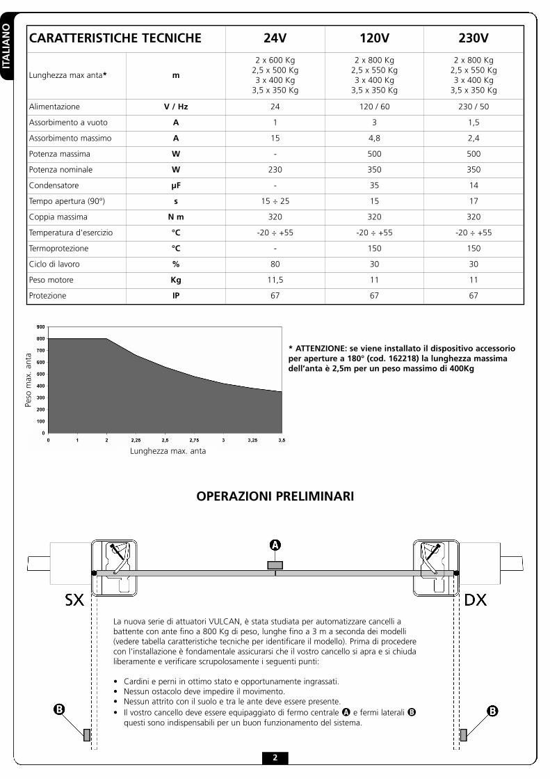
La nuova serie di attuatori VULCAN, è stata studiata per automatizzare cancelli abattente con ante fino a 800 Kg di peso, lunghe fino a 3 m a seconda dei modelli(vedere tabella caratteristiche tecniche per identificare il modello). Prima di procederecon l’installazione è fondamentale assicurarsi che il vostro cancello si apra e si chiudaliberamente e verificare scrupolosamente i seguenti punti:
• Cardini e perni in ottimo stato e opportunamente ingrassati.• Nessun ostacolo deve impedire il movimento.• Nessun attrito con il suolo e tra le ante deve essere presente.• Il vostro cancello deve essere equipaggiato di fermo centrale � e fermi laterali �
questi sono indispensabili per un buon funzionamento del sistema.
CARATTERISTICHE TECNICHE 24V 120V 230V
Lunghezza max anta* m
2 x 600 Kg2,5 x 500 Kg3 x 400 Kg
3,5 x 350 Kg
2 x 800 Kg2,5 x 550 Kg3 x 400 Kg
3,5 x 350 Kg
2 x 800 Kg2,5 x 550 Kg3 x 400 Kg
3,5 x 350 Kg
Alimentazione V / Hz 24 120 / 60 230 / 50
Assorbimento a vuoto A 1 3 1,5
Assorbimento massimo A 15 4,8 2,4
Potenza massima W - 500 500
Potenza nominale W 230 350 350
Condensatore µF - 35 14
Tempo apertura (90°) s 15 ÷ 25 15 17
Coppia massima N m 320 320 320
Temperatura d'esercizio °C -20 ÷ +55 -20 ÷ +55 -20 ÷ +55
Termoprotezione °C - 150 150
Ciclo di lavoro % 80 30 30
Peso motore Kg 11,5 11 11
Protezione IP 67 67 67
Lunghezza max. anta
Peso
max
.an
ta
* ATTENZIONE: se viene installato il dispositivo accessorioper aperture a 180° (cod. 162218) la lunghezza massimadell’anta è 2,5m per un peso massimo di 400Kg
2

ITALIA
NO
3
1. Eseguire in base alle dimensioni d’ingombro, uno scavo difondazione (si consiglia di prevedere un buon drenaggio inmodo da evitare il ristagno dell’acqua).
2. Collocare la cassa all’interno dello scavo, con il pernoallineato all’asse della cerniera.
3. Prevedere un condotto per i cavi elettrici ed uno per ildrenaggio.
4. Annegare nel calcestruzzo la cassa di fondazione, curandonela messa in bolla ed il livello.
ATTENZIONE: prima di procedere con i seguenti puntirispettare i tempi di maturazione del calcestruzzo utilizzato.
5. Inserire sul perno della cassa B la staffa di comando A.
6. Inserire la sfera E nell’apposito foro (solo nel modello 162221)dopo averla ingrassata
7. Fissare con saldatura robusta l’anta del cancello sulla leva disblocco C, quindi posizionare il tutto sulla staffa di comandoA in corrispondenza del foro
8. Ingrassare mediante apposito ugello ingrassatore D.
POSIZIONAMENTO DELLA CASSA DI FONDAZIONE E DEL SISTEMA LEVECOMANDO E SBLOCCO

ITALIANO
4
INSTALLAZIONE DEL MOTORIDUTTORE
1. Collocare il motoriduttore all’interno della cassa difondazione.
2. Fissare il motoriduttore alla cassa di fondazione serrando i4 dadi.
3. Montare la biella motore sull’albero motore e fissare la vitecon il relativo dado autobloccante.
4. Collegare la biella motore alla staffa di comando tramite laleva piegata.
5. Collegare il motore alla centrale di comando seguendo leindicazioni riportate nel seguente paragrafo.
INSTALLAZIONE DEI FERMI FINECORSA
1. Portare il cancello in posizione di massima chiusura, quindimontare la vite finecorsa come riportato in figura.
2. Portare il cancello in posizione di massima apertura, quindimontare il dado finecorsa come riportato in figura e serrarela vite.

ITALIA
NO
COLLEGAMENTI ELETTRICI
VULCAN-230V / VULCAN-120V
� ATTENZIONE: Collegare sempre il cavo di terra alsistema di terra della rete di alimentazione. Utilizzarel’apposito fastom indicato in figura e un cavo con sezioneminima di 2,5 mm2
VULCAN-24V
Cavo motoreMorsetto centrale di comando
Motore DX Motore SX
GIALLO - VERDE GND GND
BLU COMUNE COMUNE
NERO APERTURA CHIUSURA
MARRONE CHIUSURA APERTURA
Cavo motoreMorsetto centrale di comando
Motore DX Motore SX
BLU + -
MARRONE - +
5
Collegamento dell’ENCODER
� ATTENZIONE: Per il funzionamento degli encoder èindispensabile che entrambe le ante in posizione di chiusura siappoggino a un fermo meccanico.
Di seguito le indicazioni da seguire per collegare i cavidell’encoder alla centrale di comando:
� ATTENZIONE: eventuali prolunghe del cablaggiodevono essere eseguite solo con un cavo 4x0,22 schermatocon guaina in polietilene.
� ATTENZIONE: collegare la calza al comune alimentazioneaccessori [COM (-)]. Verificare che la massa dell’alimentazioneaccessori sia collegata al comune accessori
Cavo ENCODERMorsetto centrale di comando
Motore DX Motore SX
MOTORE1
� ROSSO + 24 Vdc + 24 Vdc
� NERO COM (-) COM (-)
� BLU FCA2 FCC2
� BIANCO FCC2 FCA2
MOTORE2
� ROSSO + 24 Vdc + 24 Vdc
� NERO COM (-) COM (-)
� BLU FCA1 FCC1
� BIANCO FCC1 FCA1

ITALIANO
6
SBLOCCO DI EMERGENZA
In caso di mancanza di corrente elettrica, il cancello può esseresbloccato meccanicamente agendo sul motore.Inserire la leva di sblocco in dotazione con la maniglia rivoltaverso il centro del cancello e ruotare di 180° in senso antiorario.Il ripristino dell’automazione avverrà automaticamente al primoazionamento del motore.
SCHEMA DI INSTALLAZIONE
� Attuatore VULCAN cavo 4 x 1 mm2
� Lampeggiante cavo 2 x 1,5 mm2
� Antenna cavo RG-58
� Selettore chiave o digitale cavo 2 x 1 mm2
� Costa di sicurezza (EN 12978) -
� Fotocellule internecavo 4 x 1 mm2 (RX)
cavo 2 x 1 mm2 (TX)
� Fotocellule esternecavo 4 x 1 mm2 (RX)
cavo 2 x 1 mm2 (TX)
Centrale di comando cavo 3 x 1,5 mm2

ENGLISH
7
IMPORTANT REMARKSFor any installation problems please contactV2 S.p.A. TEL. (+39) 01 72 81 24 11
V2 S.p.A. has the right to modify the product withoutprevious notice; it also declines any responsibility todamage or injury to people or things caused by improperuse or wrong installation.
� Please read this instruction manual very carefullybefore installing and programming your control unit.
• This instruction manual is only for qualified technicians, whospecialize in installations and automations.
• The contents of this instruction manual do not concern theend user.
• Every programming and/or every maintenance serviceshould be done only by qualified technicians.
AUTOMATION MUST BE IMPLEMENTED IN COMPLIANCEWITH THE EUROPEAN REGULATIONS IN FORCE:
EN 60204-1 (Machinery safety. electrical equipment ofmachines, part 1: general rules)
EN 12445 (Safe use of automated locking devices, testmethods)
EN 12453 (Safe use of automated locking devices,requirements)
• The installer must provide for a device (es. magnetotermicalswitch) ensuring the omnipolar sectioning of the equipmentfrom the power supply.The standards require a separation of the contacts of atleast 3 mm in each pole (EN 60335-1).
• The plastic case has an IP55 insulation; to connect flexibleor rigid pipes, use pipefittings having the same insulationlevel.
• Installation requires mechanical and electrical skills,therefore it shall be carried out by qualified personnel only,who can issue the Compliance Certificate concerning thewhole installation (Machine Directive 98/37/EEC, Annex IIA).
• The automated vehicular gates shall comply with thefollowing rules: EN 12453, EN 12445, EN 12978 as well asany local rule in force.
• Also the automation upstream electric system shall complywith the laws and rules in force and be carried outworkmanlike.
• The door thrust force adjustment shall be measured bymeans of a proper tool and adjusted according to the max.limits, which EN 12453 allows.
• We recommend to make use of an emergency button, to beinstalled by the automation (connected to the control unitSTOP input) so that the gate may be immediately stoppedin case of danger.
• The appliance is not to be used by children or persons withreduced physical, sensory or mental capabilities, or lack ofexperience and knowledge, unless they have been givensupervision or instruction.
• Children being supervised do not play with the appliance.
• For correct installation of the system, we recommendfollowing the instructions issued by UNAC very carefully,which can be consulted at the following web site:www.v2home.com
EC DECLARATION OF INCORPORATION FORPARTLY COMPLETED MACHINERY(Directive 2006/42/EC, Annex II-B)
The manufacturer V2 S.p.A., headquarters inCorso Principi di Piemonte 65, 12035, Racconigi (CN), Italy
Under its sole responsibility hereby declares that:
the partly completed machinery model(s):VULCAN-230V, VULCAN-120V, VULCAN-24V
Identification number and year of manufacturing:typed on nameplateDescription: electromechanical actuator for gates
- is intended to be installed on gates, to create a machineaccording to the provisions of the Directive 2006/42/EC.The machinery must not be put into service until the finalmachinery into which it has to be incorporated has beendeclared in conformity with the provisions of the Directive2006/42/EC (annex II-A).
- is compliant with the applicable essential safety requirementsof the following Directives:Machinery Directive 2006/42/EC (annex I, chapter 1)Low Voltage Directive 2006/95/EC.Electromagnetic Compatibility Directive 2004/108/EC.
The relevant technical documentation is available at the nationalauthorities’ request after justifiable request to:V2 S.p.A., Corso Principi di Piemonte 65,12035, Racconigi (CN), Italy
The person empowered to draw up the declaration and toprovide the technical documentation:Cosimo De FalcoLegal representative of V2 S.p.A.Racconigi, 11th January 2010

ENGLISH
Max. leaf lenght
Max
.le
afw
eigh
t
* WARNING: if it is installed the accessory device foropening up to 180° (code 162218), the maximum length ofthe wing is 2,5m for a maximum weight of 400Kg
PREPARATORY STEPS
The new series of actuadors VULCAN, has been devised to serve gates up to 800 Kgwith leaf up to 3 meters wide (look at the table technical data). Before proceeding withthe installation, please make sure that your gate opens and closes freely, and that:
• Hinges and pins are in optimum condition and properly greased.• No obstacles are within the moving area.• There is no friction with the ground or between the leaves.• Your gate shall be equipped with central � and side � stops, which are
fundamental for the good system operation.
8
TECHNICAL DATA 24V 120V 230V
Max. leaf lenght* m
2 x 600 Kg2,5 x 500 Kg3 x 400 Kg
3,5 x 350 Kg
2 x 800 Kg2,5 x 550 Kg3 x 400 Kg
3,5 x 350 Kg
2 x 800 Kg2,5 x 550 Kg3 x 400 Kg
3,5 x 350 Kg
Power supply V / Hz 24 120 / 60 230 / 50
Idling current A 1 3 1,5
Maximum current absorption A 15 4,8 2,4
Maximum power W - 500 500
Nominal power W 230 350 350
Capacitor µF - 35 14
Opening time (90°) s 15 ÷ 25 15 17
Maximum torque N m 320 320 320
Working temperature °C -20 ÷ +55 -20 ÷ +55 -20 ÷ +55
Thermal protection °C - 150 150
Working cycle % 80 30 30
Motor weight Kg 11,5 11 11
Protection IP 67 67 67

ENGLISH
9
1. Depending on the dimensions, dig a suitably sizedfoundation ditch (it is recommended to provide adequatedrainage in order to avoid water pooling).
2. Place the foundation box inside the trench, with the supportpivot aligned with the hinge axis.
3. Install a conduit for the electrical cables, and another fordrainage.
4. Embed the foundation box in concrete, ensuring it is leveland plumb.
WARNING: ensure that the concrete used is properly curedprior to proceeding with the following steps.
5. Insert the control rod A over the foundation box supportingpivot B.
6. Insert the ball E into the special hole (only for model 162221)after having greased it
7. Fix with a strong welding the wing of the gate on the releaselever C, then put everything on the driving bracket A incorrespondence of the hole
8. Grease the mechanism using the appropriate grease nipple D.
POSITIONING THE FOUNDATION BOX AND THE LEVER CONTROLAND BLOCKING SYSTEM

ENGLISH
INSTALLING THE MOTOR REDUCER
1. Place the motor reducer gear unit inside the foundation box.
2. Fix the motor reducer in place inside the foundation box bytightening the 4 nuts.
3. Mount the motor connecting rod on the motor drive shaft andfix the screw in place using the corresponding self-locking nut.
4. Connect the motor connecting rod to the control rod bymeans of the elbow lever.
5. Connect the motor to the control unit, following theinstructions in the following paragraph.
INSTALLATION OF THE STOP LIMITSWITCHES
1. Place the gate in the maximum closed position, and thenattach the limit switch screw as shown in the figure.
2. Place the gate in the maximum open position, and thenattach the limit switch nut as shown in the figure, andtighten the screw.
10
ENGLISH
11
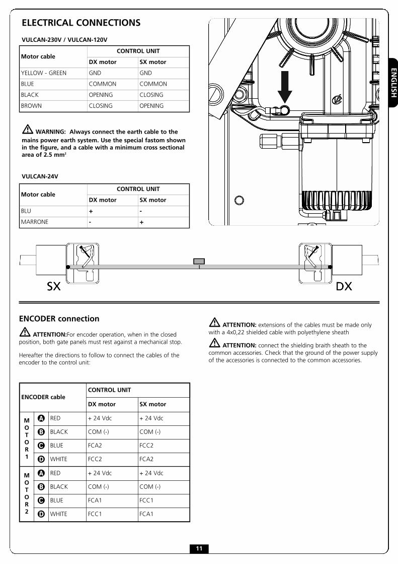
ELECTRICAL CONNECTIONS
VULCAN-230V / VULCAN-120V
� WARNING: Always connect the earth cable to themains power earth system. Use the special fastom shownin the figure, and a cable with a minimum cross sectionalarea of 2.5 mm2
VULCAN-24V
Motor cableCONTROL UNIT
DX motor SX motor
YELLOW - GREEN GND GND
BLUE COMMON COMMON
BLACK OPENING CLOSING
BROWN CLOSING OPENING
Motor cableCONTROL UNIT
DX motor SX motor
BLU + -
MARRONE - +
ENCODER connection
� ATTENTION:For encoder operation, when in the closedposition, both gate panels must rest against a mechanical stop.
Hereafter the directions to follow to connect the cables of theencoder to the control unit:
� ATTENTION: extensions of the cables must be made onlywith a 4x0,22 shielded cable with polyethylene sheath
� ATTENTION: connect the shielding braith sheath to thecommon accessories. Check that the ground of the power supplyof the accessories is connected to the common accessories.
ENCODER cableCONTROL UNIT
DX motor SX motor
MOTOR1
� RED + 24 Vdc + 24 Vdc
� BLACK COM (-) COM (-)
� BLUE FCA2 FCC2
� WHITE FCC2 FCA2
MOTOR2
� RED + 24 Vdc + 24 Vdc
� BLACK COM (-) COM (-)
� BLUE FCA1 FCC1
� WHITE FCC1 FCA1

ENGLISH
12
EMERGENCY UNBLOCKING
In the case of a power failure, the gate can be unblockedmechanically by operating the motor.
Insert the supplied unblocking lever and rotate 180° clockwise.Automation will be automatically restored the first time themotor is operated.
INSTALLATION LAYOUT
� VULCAN actuator cable 4 x 1 mm2
� Blinker cable 2 x 1,5 mm2
� Aerial cable RG-58
� Key or digital selector cable 2 x 1 mm2
� Safety edge (EN 12978) -
� Internal photocellscable 4 x 1 mm2 (RX)
cable 2 x 1 mm2 (TX)
� External photocellscable 4 x 1 mm2 (RX)
cable 2 x 1 mm2 (TX)
Control unit cable 3 x 1,5 mm2
FRANÇAIS
13
CONSEILS IMPORTANTSPour tout précision technique ou problème d’installationV2 S.p.A. dispose d’un service d’assistance clients actif pendantles horaires de bureau TEL. (+39) 01 72 81 24 11.
V2 S.p.A. se réserve le droit d’apporter d’éventuellesmodifications au produit sans préavis; elle décline en outretoute responsabilité pour tous types de dommages auxpersonnes ou aux choses dus à une utilisation imporopreou à une mauvaise installation.
� Avant de proceder avec l'installation et laprogarmmation, lire attentivement les notices.
• Ce manuel d'instruction est destiné à des techniciensqualifiés dans le domain des automatismes.
• Aucune des informations contenues dans ce livret pourraêtre utile pour le particulier.
• Tous operations de maintenance ou programation doiventêtre faites à travers de techniciens qualifiés.
L’AUTOMATION DOIT ÊTRE RÉALISÉE CONFORMÉMENT AUXDISPOSITIFS NORMATIFS EUROPÉENS EN VIGUEUR:
EN 60204-1 (Sécutité de la machinerie. Équipementélectriquedes machines, partie 1: régles générales).
EN 12445 (Sécutité dans lìutilisation de fermeturesautomatisées, méthodes d'essai).
EN 12453 (Sécurité dans l'utilisation de fermeturesautomatisées, conditions requises).
• L'installateur doit pourvoir à l'installation d'un dispositif(ex. interrupteur magnétothermique) qui assure la coupureomnipolaire de l'équipement du réseau d'alimentation.La norme requiert une séparation des contacts d'au moins3 mm pour chaque pôle (EN 60335-1).
• L'enveloppe en plastique de la carte possède uneprotection IP55, pour la connexion de tubes rigides ouflexibles utiliser des raccordements possédant le mêmeniveau de protection.
• L’installation requiert des compétences en matièred’électricité et mécaniques; doit être faite exclusivement partechniciens qualifiés en mesure de délivrer l’attestation deconformité pour l’installation (Directive 98/37/EEC, - IIA).
• Il est obligatoire se conformer aux normes suivantes pourfermetures véhiculaires automatisées: EN 12453,EN 12445, EN 12978 et à toutes éventuelles prescriptionsnationales.
• Même l’installation électrique ou on branche l’automatismedoit répondre aux normesen vigueur et être fait à règles del’art.
• La régulation de la force de poussée du vantail doit êtremesurée avec outil spécial et réglée selon les valeurs maxiadmis par la norme EN 12453.
• Nous conseillons d’utiliser un poussoir d’urgence à installerprès de l’automatisme (branché à l’entrée STOP del’armoire de commande de façon qui soit possible l’arrêtimmédiat du portail en cas de danger.
• L'appareillage ne doit pas être utilisé par des enfants oudes personnes affectés d'handicaps physiques et/oupsychiques, sans la nécessaire connaissance ousupervision de la part d'une personne compétente.
• Veillez à ce que les enfants ne puissent jouer avecl'appareillage.
• Pour une correcte mise en service du système nousconseillons de suivre attentivement les indications fourniespar l'association UNAC trouvables dans le site web suivant :www.v2home.com
DÉCLARATION D'INCORPORATION POUR LESQUASI-MACHINES (Directive 2006/42/CE, Annexe II-B)
Le fabricant V2 S.p.A., ayant son siège social a:Corso Principi di Piemonte 65, 12035, Racconigi (CN), Italie
Déclare sous sa propre responsabilité que:l’automatisme modèle:VULCAN-230V, VULCAN-120V, VULCAN-24V
Numéro de fabrication et année de construction:positionnés sur la plaque de donnéesDescription: actionneur électromécanique pour portails
• a été conçu pour être incorporé dans un portail garage envue de former une machine conformément à la Directive2006/42/CE.Cette machine ne pourra pas être mise en service avantd'être déclarée conforme aux dispositions de la directive2006/42/CE (Annexe II-A)
• est conforme exigences essentielles applicables des Directives:Directive Machines 2006/42/CE (Annexe I, Chapitre 1)Directive basse tension 2006/95/CEDirective compatibilité électromagnétique 2004/108/CE
La documentation technique est à disposition de l'autoritécompétente sur demande motivée à l'adresse suivante:V2 S.p.A., Corso Principi di Piemonte 65,12035, Racconigi (CN), Italie
La personne autorisée à signer la présente déclarationd'incorporation et à fournir la documentation technique est :Cosimo De FalcoReprésentant légal de V2 S.p.A.Racconigi, le 11/01/2010

FRANÇAIS
Longuer maxi du battant
Poid
sm
axid
uba
ttan
t
* ATTENTION: si on installe le dispositif accessoire pourouverture jusqu’à 180° (code 162218) la longueur maxi duvantail est de 2,5m pour un poids maxi de 400Kg
OPÉRATIONS PRÉLIMINAIRES
Ce nouvelle série des opérateurs électromécaniques VULCAN, a été crée pourautomatiser portails à battant jusqu’à 800 Kg de poids et vantail de 3m selon lesmodels (voir tableau caractéristiques techniques). Avant de procéder à l'installation il estfondamental de s'assurer que votre portail s'ouvre et se referme sans problème et devérifier scrupuleusement les points suivants:
• Gonds et tourillons en très bon état et graissés opportunément.• Aucune entrave ne doit empêcher le mouvement.• Aucun frottement contre le sol et entre les vantaux.• Votre portail doit être équipé d'arrêts central � et latéraux �: ceux-ci sont
indispensables pour un bon fonctionnement du système.
14
CARACTERISTIQUES TECHNIQUES 24V 120V 230V
Longuer maxi du battant* m
2 x 600 Kg2,5 x 500 Kg3 x 400 Kg
3,5 x 350 Kg
2 x 800 Kg2,5 x 550 Kg3 x 400 Kg
3,5 x 350 Kg
2 x 800 Kg2,5 x 550 Kg3 x 400 Kg
3,5 x 350 Kg
Alimentation V / Hz 24 120 / 60 230 / 50
Absorption à vide A 1 3 1,5
Absorption maximum A 15 4,8 2,4
Puissance maximum W - 500 500
Puissance nominale W 230 350 350
Condensateur µF - 35 14
Durée ouverture (90°) s 15 ÷ 25 15 17
Couple maximum N m 320 320 320
Température de service °C -20 ÷ +55 -20 ÷ +55 -20 ÷ +55
Protection thermique °C - 150 150
Cycle de travail % 80 30 30
Poids moteur Kg 11,5 11 11
Protection IP 67 67 67

FRANÇAIS
15
1. Effectuer, suivant les mesures d'encombrement, un trou defondation en ayant soin de prévoir un drainage efficace demanière à éviter la stagnation d'eau.
2. Placer la caisse à l'intérieur du trou, avec le pivot dans l'axede la charnière du portail.
3. Prévoir un conduit pour les câbles électriques et un pour ledrainage.
4. Couler le ciment sur la caisse de fondation en veillant à lacorrecte mise à niveau.
ATTENTION: avant de procéder avec les points suivantsrespecter les temps de prise du béton utilisé
5. Insérer sur le pivot de la caisse B la bride de commande A
6. Insérer la bille E dans le spécial trou (seulement dans le modèle162221) après l’avoir graissée
7. Fixer avec une soudure forte le vantail du portail sur le levierde déverrouillage C, ensuite positionner tout sur l’étrier decommande A en correspondance du trou
8. Graisser au moyen d'un bec graisseur D prévu à cet effet
POSITIONNEMENT DE LA CAISSE DE FONDATION ET DU SYSTÈMEDE LEVIERS DE COMMANDE ET DÉBLOCAGE
FRANÇAIS
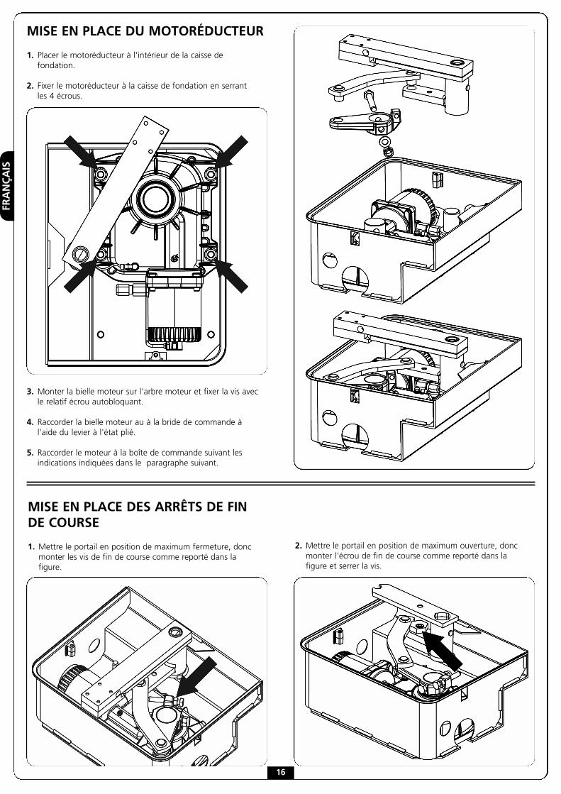
MISE EN PLACE DU MOTORÉDUCTEUR
1. Placer le motoréducteur à l'intérieur de la caisse defondation.
2. Fixer le motoréducteur à la caisse de fondation en serrantles 4 écrous.
3. Monter la bielle moteur sur l'arbre moteur et fixer la vis avecle relatif écrou autobloquant.
4. Raccorder la bielle moteur au à la bride de commande àl'aide du levier à l'état plié.
5. Raccorder le moteur à la boîte de commande suivant lesindications indiquées dans le paragraphe suivant.
MISE EN PLACE DES ARRÊTS DE FINDE COURSE
1. Mettre le portail en position de maximum fermeture, doncmonter les vis de fin de course comme reporté dans lafigure.
2. Mettre le portail en position de maximum ouverture, doncmonter l'écrou de fin de course comme reporté dans lafigure et serrer la vis.
16
FRANÇAIS
17
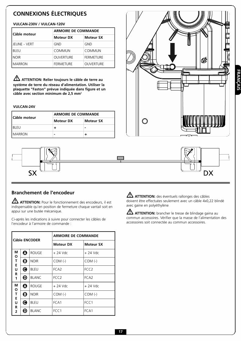
CONNEXIONS ÉLECTRIQUES
VULCAN-230V / VULCAN-120V
� ATTENTION: Relier toujours le câble de terre ausystème de terre du réseau d'alimentation. Utiliser laplaquette "Faston" prévue indiquée dans figure et uncâble avec section minimum de 2,5 mm2
VULCAN-24V
Câble moteurARMOIRE DE COMMANDE
Moteur DX Moteur SX
JEUNE - VERT GND GND
BLEU COMMUN COMMUN
NOIR OUVERTURE FERMETURE
MARRON FERMETURE OUVERTURE
Câble moteurARMOIRE DE COMMANDE
Moteur DX Moteur SX
BLEU + -
MARRON - +
Branchement de l’encodeur
� ATTENTION: Pour le fonctionnement des encodeurs, il estindispensable qu'en position de fermeture chaque vantail soit enappui sur une butée mécanique.
Ci-après les indications à suivre pour connecter les câbles del’encodeur à l’armoire de commande :
� ATTENTION: des éventuels rallonges des câblesdoivent être effectuées seulement avec un câble 4x0,22 blindéavec gaine en polyéthylène
� ATTENTION: brancher le tresse de blindage gaina aucommun accessoires. Vérifier que la masse de l’alimentation desaccessoires soit connectée au commun accessoires.
Câble ENCODERARMOIRE DE COMMANDE
Moteur DX Moteur SX
MOTEUR1
� ROUGE + 24 Vdc + 24 Vdc
� NOIR COM (-) COM (-)
� BLEU FCA2 FCC2
� BLANC FCC2 FCA2
MOTEUR2
� ROUGE + 24 Vdc + 24 Vdc
� NOIR COM (-) COM (-)
� BLEU FCA1 FCC1
� BLANC FCC1 FCA1
FRANÇAIS
18
DÉVERROUILLAGE D'URGENCE
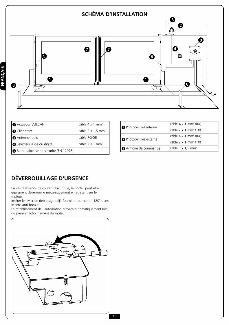
En cas d'absence de courant électrique, le portail peut êtreégalement déverrouillé mécaniquement en agissant sur lemoteur.Insérer le levier de déblocage déjà fourni et tourner de 180° dansle sens anti-horaire.Le rétablissement de l'automation arrivera automatiquement lorsdu premier actionnement du moteur.
SCHÉMA D’INSTALLATION
� Actuador VULCAN câble 4 x 1 mm2
� Clignotant câble 2 x 1,5 mm2
� Antenne radio câble RG-58
� Selecteur à clé ou digital câble 2 x 1 mm2
� Barre palpeuse de sécurité (EN 12978) -
� Photocellules internecâble 4 x 1 mm2 (RX)
câble 2 x 1 mm2 (TX)
� Photocellules externecâble 4 x 1 mm2 (RX)
câble 2 x 1 mm2 (TX)
Armoire de commande câble 3 x 1,5 mm2

ESPAÑOL
ADVERTENCIAS IMPORTANTESPor cualquier problema técnico ponerse en contacto con elservicio asistencia V2 S.p.A. TEL. (+39) 01 72 81 24 11
La V2 S.p.A. se reserva el derecho de aportareventuales modificaciones al producto sin previo aviso;además, no se hace responsable de daños a personas ocosas debidos a un uso impropio o a una instalaciónerrónea.
� Antes de proceder a la instalación y programaciónes aconsejable leer bien las instrucciones.
• Dicho manual está destinado exclusivamente a técnicoscalificados en las instalaciones de automatismos.
• Ninguna de las informacciones contenidas en dicho manualpuede ser de utilidad para el usuario final.
• Cualquier operación de mantenimiento y programacióntendrá que ser hecha por técnicos calificados en lasinstalaciones de automatismos.
LA AUTOMATIZACION DEBE SER REALIZADA ENCONFORMIDAD A LAS VIGENTES NORMATIVAS EUROPEAS:
EN 60204-1 (Seguridad de la maquinaria. Equipamientoeléctrico de las máquinas, partes 1: reglasgenerales).
EN 12445 (Seguridad en el uso de cierres automatizados,metodos de prueba)
EN 12453 (Seguridad en el uso de cierres automatizados,requisitos)
• El instalador debe proveer la instalación de un dispositivo(ej. interruptor magnetotérmico) que asegure elseccionamiento omnipolar del aparato de la red dealimentación. La normativa requiere una separación de loscontactos de mínimo 3 mm en cada polo (EN 60335-1).
• Para la conexión de tubos rígidos o flexibles y pasacables,utilizar manguitos conformes al grado de protección IP55como la caja de plástico que contiene la placa.
• La instalación requiere competencias en el campo eléctricoy mecánico; debe ser realizada únicamente por personalcualificado en grado de expedir la declaración deconformidad en la instalación (Directiva máquinas98/37/EEC, anexo IIA).
• Es obligatorio atenerse a las siguientes normas para cierresautomatizados con paso de vehículos: EN 12453,EN 12445, EN 12978 y a las eventuales prescripcionesnacionales.
• Incluso la instalación eléctrica antes de la automatizacióndebe responder a las vigentes normativas y estar realizadacorrectamente.
• La regulación de la fuerza de empuje de la hoja debemedirse con un instrumento adecuado y regulada deacuerdo con los valores máximos admitidos por lanormativa EN 12453.
• El equipo no debe ser utilizado por infantes o personas condiscapacidades físicas o psíquicas, sin el debidoconocimiento o supervisión por parte de una personacompetente.
• Vigile a los niños de modo que no jueguen con el equipo.
19
• Para una correcta puesta en servicio del sistemarecomendamos seguir cuidadosamente las indicacionesexpedidas por la asociación UNAC disponibles en lasiguiente dirección de Internet: www.v2home.com
DECLARACIÓN DE INCORPORACIÓN PARA LASCASI MÁQUINAS (Directiva 2006/42/CE, Anexo II-B)
El fabricante V2 S.p.A., con sede enCorso Principi di Piemonte 65, 12035, Racconigi (CN), Italia
Declara bajo su propia responsabilidad que:el automatismo modelo:VULCAN-230V, VULCAN-120V, VULCAN-24V
Matrícula y año de construcción: puestos en la placa deidentificación de datosDescripción: Servomotor electromecánico para cancelas
• está destinado a ser incorporado en una cancela paraconstituir una máquina conforme a la Directiva 2006/42/CE.Dicha máquina no podrá ser puesta en servicio antes de serdeclarada conforme con las disposiciones de la directiva2006/42/CE (Anexo II-A)
• es conforme con los requisitos esenciales aplicables de lasDirectivas:Directiva de Máquinas 2006/42/CE (Anexo I, Capítulo 1)Directiva de baja tensión 2006/95/CEDirectiva de compatibilidad electromagnética 2004/108/CE
La documentación técnica está a disposición de la autoridadcompetente bajo petición fundada en:V2 S.p.A., Corso Principi di Piemonte 65,12035, Racconigi (CN), Italia
La persona autorizada para firmar la presente declaración deincorporación y a proporcionar la documentación técnica:Cosimo De FalcoRepresentante legal de V2 S.p.A.Racconigi, a 11/01/2010

ESPAÑOL
Longitud máx. hoja
Peso
máx
.ho
ja
* ATENCION : si se instala el dispositivo accesorio paraapertura hasta 180° (código 162218) la longitud máxima dela hoja es de 2,5m por un peso máximo de 400Kg
OPERACIONES PRELIMINARES
La nueva serie de operadores VULCAN ha sido estudiada para automatizar cancelasbatientes pesadas hasta 800 Kg, con longitud de hoja hasta 3m según las versiones (vertabla características técnicas).Antes de proceder con la instalación, es fundamental asegurarse de que vuestra cancelaabra y cierre libremente y verificar los siguientes puntos:
• Bisagras y pernios en estado óptimo y oportunamente lubricados.• Ningún obstáculo debe impedir el movimiento.• Ningún roce entre el suelo y las hojas.• Su cancela ha de estar equipada de topes centrales � y laterales �:
estos son indispensables para un buen funcionamiento del sistema.
20
DATOS TÉCNICOS 24V 120V 230V
Longitud máx. hoja m
2 x 600 Kg2,5 x 500 Kg3 x 400 Kg
3,5 x 350 Kg
2 x 800 Kg2,5 x 550 Kg3 x 400 Kg
3,5 x 350 Kg
2 x 800 Kg2,5 x 550 Kg3 x 400 Kg
3,5 x 350 Kg
Alimentacion V / Hz 24 120 / 60 230 / 50
Absorcion en vacio A 1 3 1,5
Absorción máxima A 15 4,8 2,4
Potencia máxima W - 500 500
Potencia nominal W 230 350 350
Condensator µF - 35 14
Tiempo de apertura (90°) s 15 ÷ 25 15 17
Par máximo N m 320 320 320
Temperatura de servicio °C -20 ÷ +55 -20 ÷ +55 -20 ÷ +55
Termoproteccion °C - 150 150
Ciclo de trabajo % 80 30 30
Peso operador Kg 11,5 11 11
Protección IP 67 67 67
ESPAÑOL
21
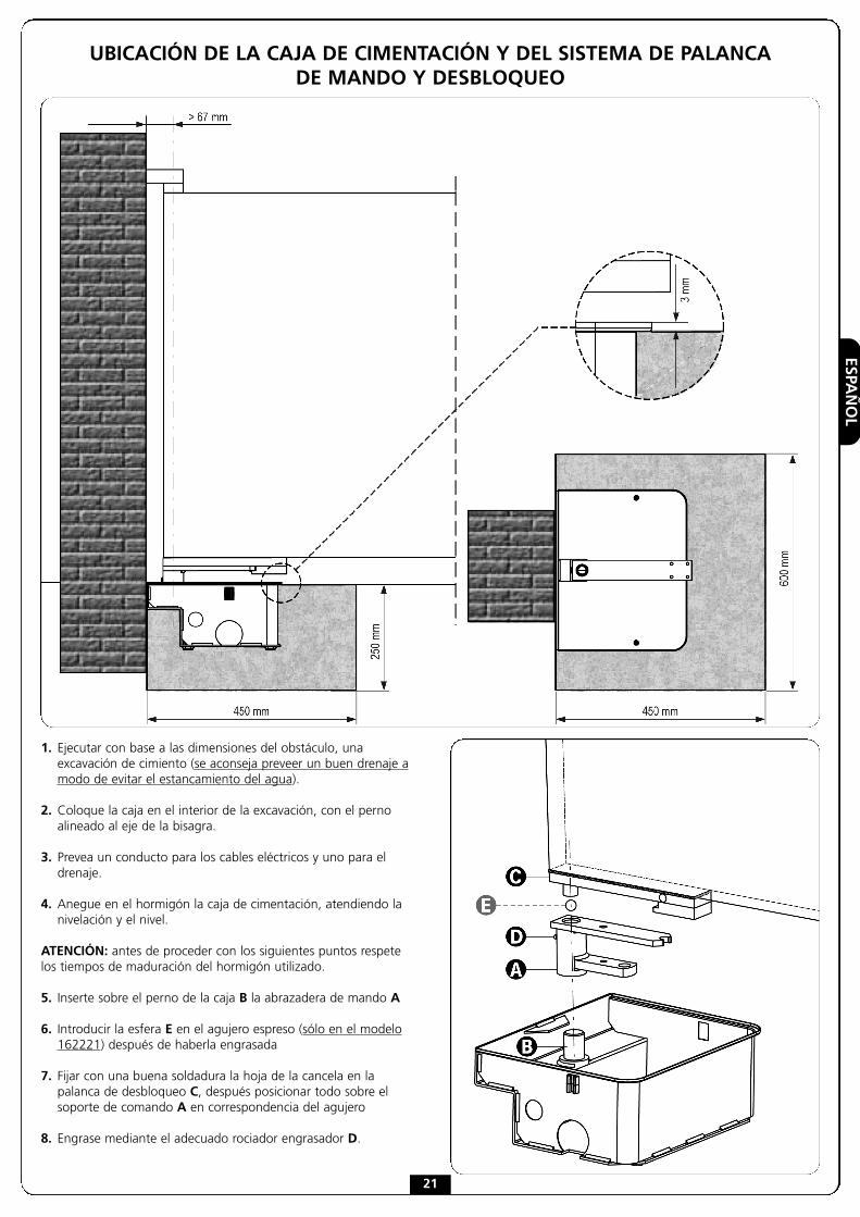
1. Ejecutar con base a las dimensiones del obstáculo, unaexcavación de cimiento (se aconseja preveer un buen drenaje amodo de evitar el estancamiento del agua).
2. Coloque la caja en el interior de la excavación, con el pernoalineado al eje de la bisagra.
3. Prevea un conducto para los cables eléctricos y uno para eldrenaje.
4. Anegue en el hormigón la caja de cimentación, atendiendo lanivelación y el nivel.
ATENCIÓN: antes de proceder con los siguientes puntos respetelos tiempos de maduración del hormigón utilizado.
5. Inserte sobre el perno de la caja B la abrazadera de mando A
6. Introducir la esfera E en el agujero espreso (sólo en el modelo162221) después de haberla engrasada
7. Fijar con una buena soldadura la hoja de la cancela en lapalanca de desbloqueo C, después posicionar todo sobre elsoporte de comando A en correspondencia del agujero
8. Engrase mediante el adecuado rociador engrasador D.
UBICACIÓN DE LA CAJA DE CIMENTACIÓN Y DEL SISTEMA DE PALANCADE MANDO Y DESBLOQUEO
ESPAÑOL
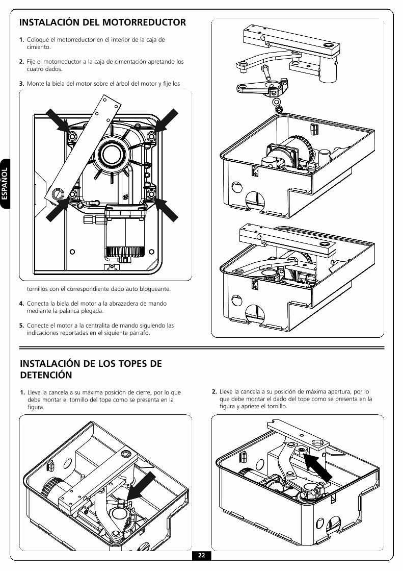
INSTALACIÓN DEL MOTORREDUCTOR
1. Coloque el motorreductor en el interior de la caja decimiento.
2. Fije el motorreductor a la caja de cimentación apretando loscuatro dados.
3. Monte la biela del motor sobre el árbol del motor y fije los
tornillos con el correspondiente dado auto bloqueante.
4. Conecta la biela del motor a la abrazadera de mandomediante la palanca plegada.
5. Conecte el motor a la centralita de mando siguiendo lasindicaciones reportadas en el siguiente párrafo.
INSTALACIÓN DE LOS TOPES DEDETENCIÓN
1. Lleve la cancela a su máxima posición de cierre, por lo quedebe montar el tornillo del tope como se presenta en lafigura.
2. Lleve la cancela a su posición de máxima apertura, por loque debe montar el dado del tope como se presenta en lafigura y apriete el tornillo.
22
ESPAÑOL
23
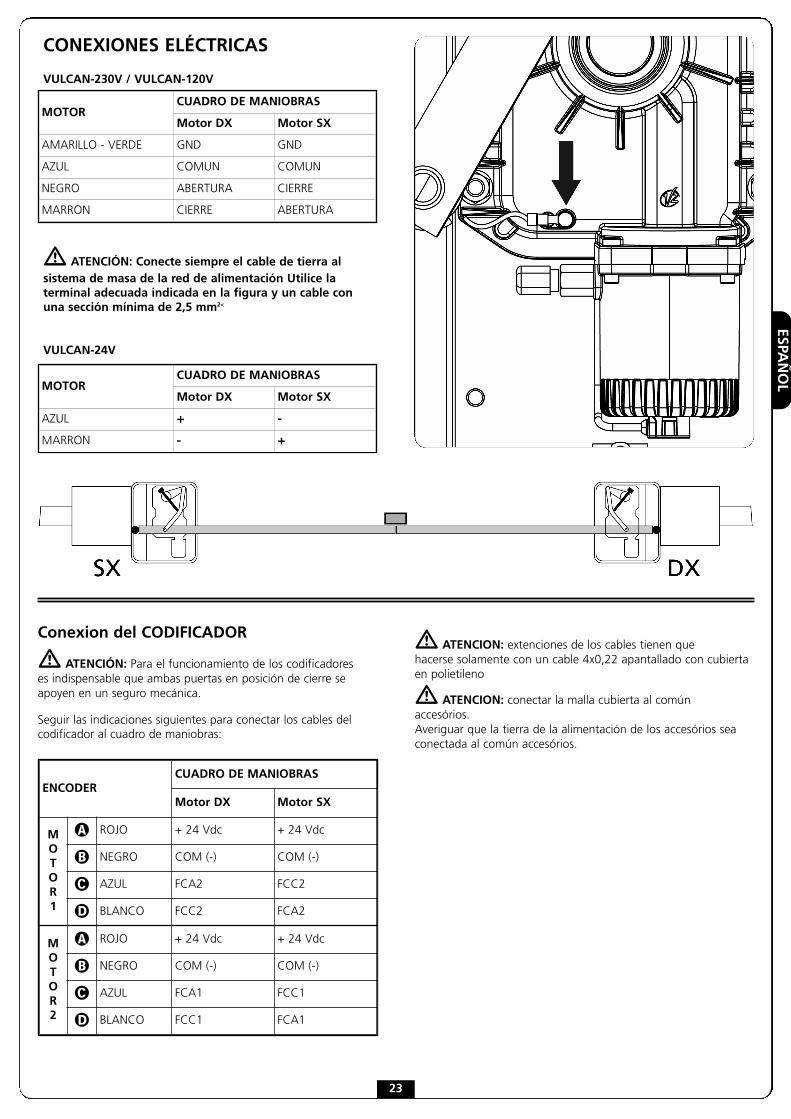
CONEXIONES ELÉCTRICAS
VULCAN-230V / VULCAN-120V
� ATENCIÓN: Conecte siempre el cable de tierra alsistema de masa de la red de alimentación Utilice laterminal adecuada indicada en la figura y un cable conuna sección mínima de 2,5 mm2<
VULCAN-24V
MOTORCUADRO DE MANIOBRAS
Motor DX Motor SX
AMARILLO - VERDE GND GND
AZUL COMUN COMUN
NEGRO ABERTURA CIERRE
MARRON CIERRE ABERTURA
MOTORCUADRO DE MANIOBRAS
Motor DX Motor SX
AZUL + -
MARRON - +
Conexion del CODIFICADOR
� ATENCIÓN: Para el funcionamiento de los codificadoreses indispensable que ambas puertas en posición de cierre seapoyen en un seguro mecánica.
Seguir las indicaciones siguientes para conectar los cables delcodificador al cuadro de maniobras:
� ATENCION: extenciones de los cables tienen quehacerse solamente con un cable 4x0,22 apantallado con cubiertaen polietileno
� ATENCION: conectar la malla cubierta al comúnaccesórios.Averiguar que la tierra de la alimentación de los accesórios seaconectada al común accesórios.
ENCODERCUADRO DE MANIOBRAS
Motor DX Motor SX
MOTOR1
� ROJO + 24 Vdc + 24 Vdc
� NEGRO COM (-) COM (-)
� AZUL FCA2 FCC2
� BLANCO FCC2 FCA2
MOTOR2
� ROJO + 24 Vdc + 24 Vdc
� NEGRO COM (-) COM (-)
� AZUL FCA1 FCC1
� BLANCO FCC1 FCA1

ESPAÑOL
24
DESBLOQUEO DE EMERGENCIA
En caso de ausencia de la corriente eléctrica, la cancela se puededesbloquear mecánicamente actuando sobre el motor.Inserte la palanca de desbloqueo incluido y gírela 180° ensentido contrario a las manecillas del reloj.El restablecimiento de la automatización ocurriráautomáticamente con el primer impulso del motor.
ESQUEMA DE INSTALACIÓN
� Actuador VULCAN cable 4 x 1 mm2
� Lámpara de señalización cable 2 x 1,5 mm2
� Antena cable RG-58
� Selector a llave o digital cable 2 x 1 mm2
� Banda de seguridad (EN 12978) -
� Fotocélulas internascable 4 x 1 mm2 (RX)
cable 2 x 1 mm2 (TX)
� Fotocélulas externascable 4 x 1 mm2 (RX)
cable 2 x 1 mm2 (TX)
Cuadro de maniobras cable 3 x 1,5 mm2

PORTUGUÊS
25
AVISOS IMPORTANTESPara esclarecimentos técnicos ou problemas de instalação a V2dispõe de um serviço de assistência clientes activo em horário deabertura. TEL. (+39) 01 72 81 24 11
V2 reserva-se o direito de efectuar eventuais alterações aoproduto sem aviso prévio; declina ainda qualquerresponsabilidade pelos danos a pessoas ou coisasoriginados por uso impróprio ou instalação errada.
� LER ATENTAMENTE O SEGUINTE MANUAL DE
INSTRUÇÕES ANTES DE PROCEDER À INSTALAÇÃO.
• O presente manual de instruções destina-se exclusivamenteao pessoal técnico qualificado no sector das instalações deautomações.
• Nenhuma das informações contidas no manual pode serinteressante o útil ao utilizador final.
• Qualquer operação de manutenção ou de programaçãodeve ser realizada exclusivamente por pessoal qualificado.
A AUTOMAÇÃO DEVE SER REALIZADA EM CONFORMIDADECOM AS NORMAS EUROPEIAS VIGENTES:EN 60204-1 (Segurança das máquinas, equipamento
eléctrico das máquinas, parte 1: regras gerais).EN 12445 (Segurança nos cerramentos automatizados,
métodos de teste).EN 12453 (Segurança no uso de cerramentos
automatizados, requisitos).
• O instalador deve instalar um dispositivo (ex. interruptortérmico magnético), que assegure o seccionamento detodos os pólos do sistema da rede de alimentação.As normas exigem uma separação dos contactos de pelomenos 3 mm em cada polo (EN 60335-1).
• Para a conexão dos tubos rijos e flexíveis ou passador decabos, utilizar junções conformes ao grau de protecção IP55ou superior.
• A instalação requer competências no sector eléctrico emecânico; só deve ser efectuada por pessoal qualificadohabilitado a passar a declaração de conformidade de tipo Apara a instalação completa (Directriz máquinas 98/37/EEC,apenso IIA).
• É obrigatório respeitar as seguintes normas paracerramentos veiculares automatizados: EN 12453,EN 12445, EN 12978 e as eventuais prescrições nacionais.
• A instalação a montante da automação também deverespeitar as normas vigentes e ser realizadas conforme asregras da arte.
• A regulação da força de impulso da folha deve medir-secom ferramenta própria e ser regulada conforme os valoresmáximos admitidos pela norma EN 12453.
• Aconselhamos utilizar um botão de emergência, a serinstalado nas proximidades da automação, (conectado coma entrada STOP da placa de comando) de maneira que sejapossível parar imediatamente o portão no caso de perigo.
• A aparelhagem não deve ser utilizada por crianças oupessoas com deficiências físicas ou psíquicas sem o devidoconhecimento ou supervisão de pessoa competente.
• Não deixe as crianças brincarem com a aparelhagem.
• Se o cabo de alimentação estiver danificado, a suasubstituição deverá ser feita pelo fabricante, pelo seuserviço de assistência ou, em todo caso, por pessoa comqualificação similar, de maneira a prevenir qualquer risco.
• Para uma correta colocação em serviço do sistemarecomendamos observar cuidadosamente as indicaçõesfornecidas pela associação UNAC e disponibilizadas noseguinte endereço Internet: www.v2home.com
DECLARAÇÃO DE INCORPORAÇÃO PARA ASQUASE-MÁQUINAS (Directiva 2006/42/CE, Anexo II-B)
O fabricante V2 S.p.A., com sede emCorso Principi di Piemonte 65, 12035, Racconigi (CN), Italia
Declara sob a própria responsabilidade que:O automatismo modelo:VULCAN-230V, VULCAN-120V, VULCAN-24V
Matrícula e ano de fabricação : referidos na chapa de dadosDescrição: Actuador electromecânico para portões
- Destina-se a ser incorporada em portão para constituir umamáquina nos termos da Directiva 2006/42/CE.A máquina não pode entrar em exercício antes de serdeclarada conforme às disposições da directiva 2006/42/CE(Anexo II-A)
- É conforme aos requisitos essenciais aplicáveis das Directivas :Directiva Máquinas 2006/42/CE (Anexo I, Capítulo 1)Directiva baixa tensão 2006/95/CEDirectiva compatibilidade electromagnética 2004/108/CE
A documentação técnica está à disposição da autoridadecompetente a pedido motivado junto à:V2 S.p.A., Corso Principi di Piemonte 65,12035, Racconigi (CN), Italia
A pessoa autorizada a assinar a presente declaração deincorporação e a fornecer a documentação técnica:Cosimo De FalcoRepresentante legal de V2 S.p.A.Racconigi, il 11/01/2010
PORTUGUÊS
26
Comprimento máximo da folha
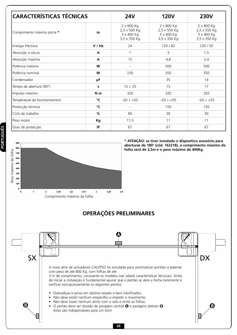
* ATENÇÃO: se tiver instalado o dispositivo acessório paraaberturas de 180° (cód. 162218), o comprimento máximo dafolha será de 2,5m e o peso máximo de 400Kg.
Peso
máx
imo
dafo
lha
OPERAÇÕES PRELIMINARES
A nova série de actuadores CALYPSO foi estudada para automatizar portões a batentecom peso de até 800 Kg, com folhas de até3 m de comprimento, consoante os modelos (ver tabela características técnicas). Antesde iniciar a instalação é fundamental apurar que o portão se abre e fecha livremente everificar escrupulosamente os seguintes pontos:
• Dobradiças e pinos em óptimo estado e bem lubrificados.• Não deve existir nenhum empecilho a impedir o movimento.• Não deve haver nenhum atrito com o solo e entre as folhas.• O portão deve ser dotado de paragem central � e paragens laterais �:
estas são indispensáveis para um bom
CARACTERÍSTICAS TÉCNICAS 24V 120V 230V
Comprimento máximo porta * m
2 x 600 Kg2,5 x 500 Kg3 x 400 Kg
3,5 x 350 Kg
2 x 800 Kg2,5 x 550 Kg3 x 400 Kg
3,5 x 350 Kg
2 x 800 Kg2,5 x 550 Kg3 x 400 Kg
3,5 x 350 Kg
Energia Eléctrica V / Hz 24 120 / 60 230 / 50
Absorção a vácuo A 1 3 1,5
Absorção máxima A 15 4,8 2,4
Potência máxima W - 500 500
Potência nominal W 230 350 350
Condensador µF - 35 14
Tempo de abertura (90°) s 15 ÷ 25 15 17
Impulso máximo N m 320 320 320
Température de fonctionnement °C -20 ÷ +55 -20 ÷ +55 -20 ÷ +55
Protecção térmica °C - 150 150
Ciclo de trabalho % 80 30 30
Peso motor Kg 11,5 11 11
Grau de protecção IP 67 67 67

PORTUGUÊS
27
1. Fazer uma escavação de acordo com as medidas da caixa(recomenda-se uma boa drenagem de forma a evitar aestagnação da água).
2. Colocar a caixa dentro da escavação realizada, de forma a queo perno fique alinhado com o eixo da dobradiça.
3. Instalar uma conduta para os cabos eléctricos e uma para adrenagem.
4. Mergulhar a caixa de fundação no betão, verificando o prumoe o nível.
ATENÇÃO: antes de dar seguimento às etapas seguintes,respeitar a fase de endurecimento do betão.
5. Introduzir o perno B da caixa no estribo de comando A.
6. Após ter lubrificado a esfera E, inseri-la no orifício apropriado(apenas no modelo 162221).
7. Soldar bem a folha do portão na alavanca de desbloqueio C,em seguida posicionar todas as peças no estribo de comandoA no orifício correspondente.
8. Lubrificar o mecanismo utilizando o respectivo bocallubrificante D.
POSICIONAMENTO DA CAIXA DE FUNDAÇÃO E DO SISTEMADE ALAVANCAS DE COMANDO E DESBLOQUEIO
PORTUGUÊS
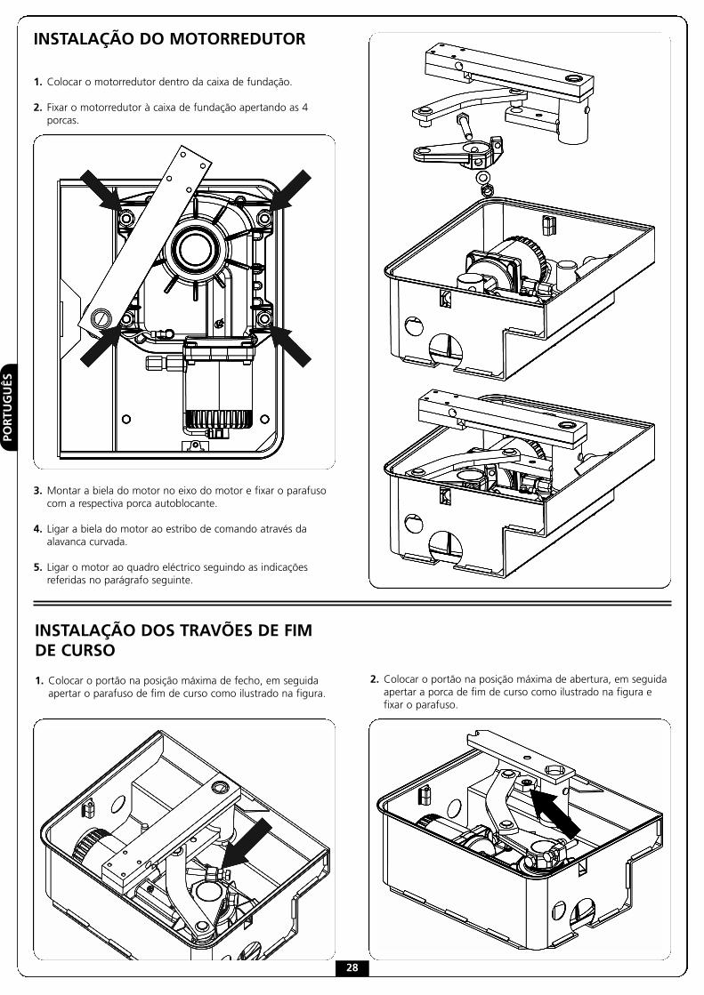
INSTALAÇÃO DO MOTORREDUTOR
1. Colocar o motorredutor dentro da caixa de fundação.
2. Fixar o motorredutor à caixa de fundação apertando as 4porcas.
3. Montar a biela do motor no eixo do motor e fixar o parafusocom a respectiva porca autoblocante.
4. Ligar a biela do motor ao estribo de comando através daalavanca curvada.
5. Ligar o motor ao quadro eléctrico seguindo as indicaçõesreferidas no parágrafo seguinte.
INSTALAÇÃO DOS TRAVÕES DE FIMDE CURSO
1. Colocar o portão na posição máxima de fecho, em seguidaapertar o parafuso de fim de curso como ilustrado na figura.
2. Colocar o portão na posição máxima de abertura, em seguidaapertar a porca de fim de curso como ilustrado na figura efixar o parafuso.
28

PORTUGUÊS
29
LIGAÇÕES ELÉCTRICAS
VULCAN-230V / VULCAN-120V
� ATENÇÃO: Ligar sempre o cabo de terra ao sistemada rede de alimentação. Utilizar o respectivo terminal detipo faston indicado na figura e um cabo com secçãomínima de 2,5 mm2
VULCAN-24V
MOTORQUADRO ELÉCTRICO
Motor DX Motor SX
AMARELO - VERDE GND GND
AZUL COMUM COMUM
PRETO ABERTURA FECHO
CASTANHO FECHO ABERTURA
MOTORQUADRO ELÉCTRICO
Motor DX Motor SX
AZUL + -
CASTANHO - +
Ligações do ENCODER
� ATENÇÃO: Para o funcionamento dos codificadores éindispensável que as duas folhas na posição de fechaduraencostem numa paragem mecânica.
Abaixo as indicações a seguir para ligar os cabos do codificadorao quadro eléctrico:
� ATENÇÃO: Eventuais extensões dos cabos devem serapenas efectuadas com um cabo blindado 4x0,22 comrevestimento em polietileno.
� ATENÇÃO: ligar o cabo de protecção ao comum dosacessórios. Verificar se a massa de alimentação dos acessóriosestá ligada ao comum dos acessórios.
ENCODERQUADRO ELÉCTRICO
Motor DX Motor SX
MOTOR1
� VERMELHO + 24 Vdc + 24 Vdc
� PRETO COM (-) COM (-)
� AZUL FCA2 FCC2
� BRANCO FCC2 FCA2
MOTOR2
� VERMELHO + 24 Vdc + 24 Vdc
� PRETO COM (-) COM (-)
� AZUL FCA1 FCC1
� BRANCO FCC1 FCA1

PORTUGUÊS
30
DESBLOQUEIO DE EMERGÊNCIA
Em caso de falta de energia eléctrica, o portão pode serdesbloqueado mecanicamente actuando no motor.Introduzir a alavanca de desbloqueio fornecida e rodá-la 180° nosentido contrário aos ponteiros do relógio.A automação será automaticamente restabelecida no primeiroarranque do motor.
ESQUEMA DE INSTALAÇÃO
� Actuador VULCAN cabo 4 x 1 mm2
� Intermitência cabo 2 x 1,5 mm2
� Antena cabo RG-58
� Selector com chave ou digital cabo 2 x 1 mm2
� Banda sensível de segurança (EN 12978) -
� Células fotoeléctricasinternas
cabo 4 x 1 mm2 (RX)cabo 2 x 1 mm2 (TX)
� Células fotoeléctricasexternas
cabo 4 x 1 mm2 (RX)cabo 2 x 1 mm2 (TX)
Quadro de comando cabo 3 x 1,5 mm2

DEUTSC
H
31
WICHTIGE HINWEISE FÜR DENINSTALLATEURFür tecnische Erläuterungen oder Installtionsprobleme verfügt dieFirma V2 S.p.A. über einen Kundendienst, der zu Bürozeitenunter der Telefonnummer (+39) 01 72 81 24 11 erreicht werdenkann.
Die Firma V2 S.p.A. behält sich das Recht vor, das Produktohne vorherige Ankündigungen abzuändern; dieÜbernahme der Haftung für Schäden an Personen oderSachen, die auf einen unsachgemäßen Gebrauch oder einefehlerhafte Installation zurückzuführen sind, wirdabgelehnt.
� Um die Steuerung fehlerfrei zu installieren und
programmieren zu können, lesen Sie bitte dieseBedienungsanleitung sehr aufmerksam durch.
• Diese Bedienungsanleitung ist nur für Fachtechniker, die aufInstallationen und Automationen von Toren.
• Keine Information dieser Bedienungsanleitung ist für denEndbenutzer nützlich.
• Jede Programmierung und/oder jede Wartung sollte nur vongeschulten Technikern vorgenommen werden.
DIE AUTOMATISIERUNG MUSS IN ÜBEREINSTIMMUNG MITDEN GELTENDEN EUROPÄISCHEN NORMEN ERFOLGEN:EN 60204-1 (Sicherheit der Maschine elektrische
Ausrüstungen von Maschinen, Teil 1: allgemeineAnforderungen)
EN 12445 (Nutzungssicherheit kraftbetätigter Torerüfverfahren)
EN 12453 (Nutzungssicherheit kraftbetätigter ToreAnforderungen)
• Der Installateur muss eine Vorrichtung (z.B. thermomagn.Schalter) anbringen, die Trennung aller Pole des Geräts zumVersorgungsnetz garantiert. Die Norm verlangt eine Trennungder Kontakte von mindestens 3 mm an jedem Pol (EN 60335-1).
• Die Installation erfordert Kenntnisse auf den Gebieten derElektrik und Mechanik; sie darf ausschließlich vonkompetentem Personal durchgeführt werden, welchesberechtigt ist, eine vollständige Konformitätserklärung vomTyp A auszustellen (Maschinenrichtlinie 98/37/EEC, Anlage IIA).
• Auch die elektrische Anlage der Automatik muss dengeltenden Normen genügen, und fachgerecht installiertwerden.
• Die Überprüfung der Schubkraft und der Umkehrzeiten mussim Fall einer Hinderniserkennung seitens des Flügels den inder Norm EN 12453 aufgeführten Mindestanforderungenentsprechen.
• Kinder und Behinderten (körperlich oder geistig) sollendieses Gerät nicht benutzen, au_er wenn eine erwachseneund bewanderte Person dabei ist.
• Erlauben Sie nicht Ihren Kindern, mit diesem Gerät zuspielen.
• Wenn der Versogungkabel beschädigt ist, soll er von derHerstellerfirma oder jedenfalls von einem Fachmann ersetzetwerden, um eventuelle Gefahren zu vermeiden.
• Zur korrekten Inbetriebnahme des Systems empfehlen wir,aufmerksam die von der Vereinigung UNAC auf der Webseitewww.v2home.com aufgeführten Hinweise zu berücksichtigen.
INKORPORATIONSERKLÄRUNG FÜRUNVOLLSTÄNDIGE MASCHINEN(Richtlinie 2006/42/EG, Anhang II-B)
Der Hersteller V2 S.p.A., mit Sitz inCorso Principi di Piemonte 65, 12035, Racconigi (CN), Italien
Erklärt unter eigener Haftung, dass:der Automatismus Modell:VULCAN-230V, VULCAN-120V, VULCAN-24V
Seriennummer und Baujahr: auf dem TypenschildBeschreibung: Elektromechanisches Stellglied für Tore
- für die Inkorporation in ein/e Tor bestimmt ist und eineMaschine darstellt gemäß Richtlinie 2006/42/EG.Diese Maschine darf nicht in Betrieb genommen werdenbevor sie nicht als den Bestimmungen der Richtlinie2006/42/EG (Anhang II-A) konform erklärt wird
- konform mit den wesentlichen anwendbaren Bestimmungender Richtlinien ist:Maschinenrichtlinie 2006/42/EG (Anhang I, Kapitel 1)Niederspannungsrichtlinie 2006/95/EGRichtlinie über elektromagnetische Verträglichkeit 2004/108/EG
Die technische Dokumentation steht den zuständigen Behördenauf begründete Anfrage zur Verfügung bei:V2 S.p.A., Corso Principi di Piemonte 65,12035, Racconigi (CN), Italien
Folgende Person ist autorisiert, die Inkorporationserklärung zuunterzeichnen und die technische Dokumentation zur Verfügungzu stellen:Cosimo De FalcoGesetzlicher Vertreter von V2 S.p.A.Racconigi, den 11/01/2010

DEUTSCH
32
VORBEREITNDE ARBEITSSCHRITTE
Die neue Serie von Antrieben VULCAN ist „geboren“ um Flügeltore bis 800 Kg und mitTor-Flügeln bis 3 Meter Länge zu führen. (Bitte sehen Sie in die Tafel mit den technischenDaten). Vor der Installation muss sichergestellt werden, dass sich das Tor hindernisfreiöffnen und schließen lässt, ferner ist es auf folgendeVoraussetzungen zu prüfen:
• Angeln und Stifte müssen sich in einwandfreiem Zustand befinden und hinreichendgeschmiert sein.
• Kein Hindernis darf die Bewegung beeinträchtigen.• Es darf keine Reibung zwischen den Torflügeln und dem Grund bestehen.• Ihr Tor muss mit zentralen � und seitlichen � Stoppern ausgerüstet sein: Diese sind
für die korrekte Funktion des Systems unentbehrlich.
Max. Torflügelweite
Max
.To
rflü
gelg
ewic
ht
* Achtung: wenn wird diesem Anrtrieb fuer 180 ° installiert(cod 162218) die maximale Laenge ist 2,5 mt fuer einGewicht von 400 kg.
TECHNISCHE DATEN 24V 120V 230V
Max. Torflügelweite * m
2 x 600 Kg2,5 x 500 Kg3 x 400 Kg
3,5 x 350 Kg
2 x 800 Kg2,5 x 550 Kg3 x 400 Kg
3,5 x 350 Kg
2 x 800 Kg2,5 x 550 Kg3 x 400 Kg
3,5 x 350 Kg
Versongung V / Hz 24 120 / 60 230 / 50
Stromaufnahme ohne Belastung A 1 3 1,5
Maximale Stromaufnahme A 15 4,8 2,4
Maximale Leistung W - 500 500
Nominale Leistung W 230 350 350
Kondensator µF - 35 14
Öffnungszeit (90°) s 15 ÷ 25 15 17
Maximales Moment N m 320 320 320
Betriebstemperatur °C -20 ÷ +55 -20 ÷ +55 -20 ÷ +55
Wärmeschutz °C - 150 150
Arbeitszyklus % 80 30 30
Motorgewicht Kg 11,5 11 11
Schutzart IP 67 67 67
DEUTSC
H
33
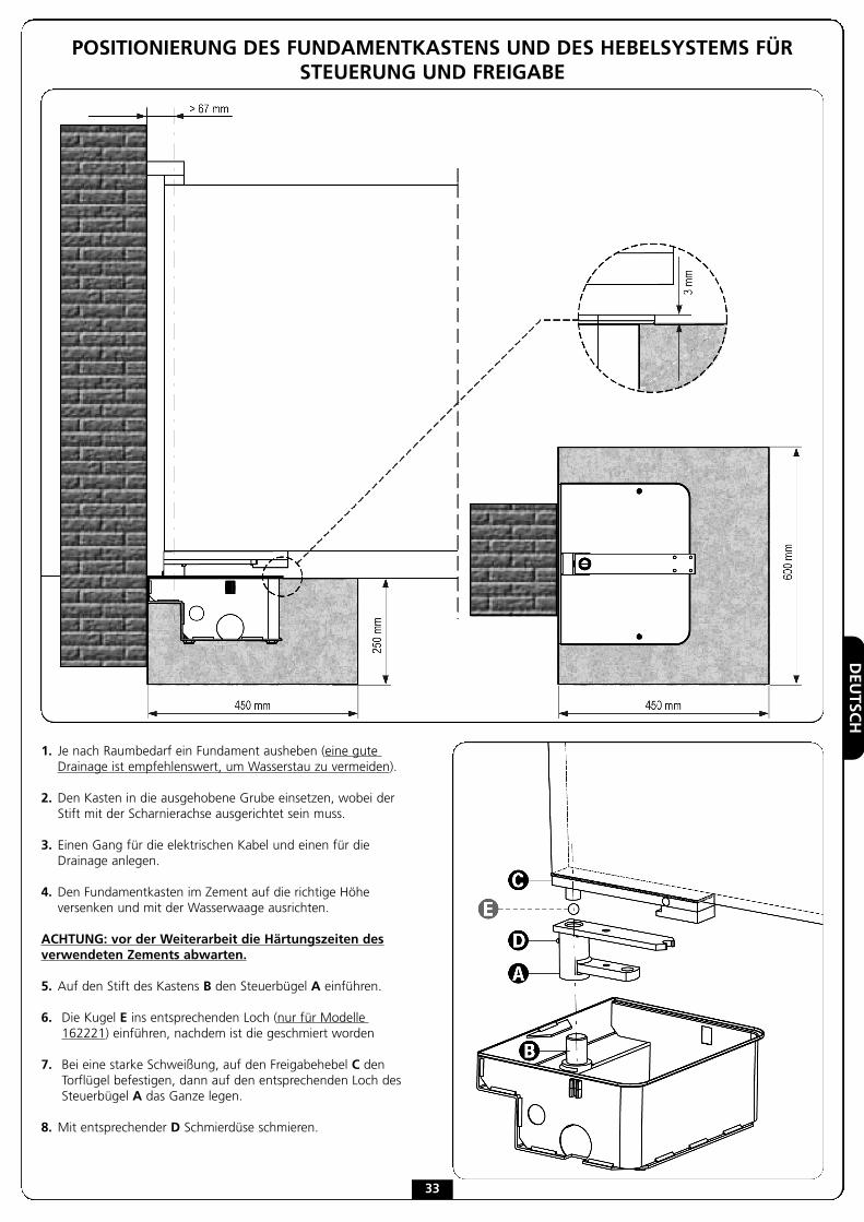
1. Je nach Raumbedarf ein Fundament ausheben (eine guteDrainage ist empfehlenswert, um Wasserstau zu vermeiden).
2. Den Kasten in die ausgehobene Grube einsetzen, wobei derStift mit der Scharnierachse ausgerichtet sein muss.
3. Einen Gang für die elektrischen Kabel und einen für dieDrainage anlegen.
4. Den Fundamentkasten im Zement auf die richtige Höheversenken und mit der Wasserwaage ausrichten.
ACHTUNG: vor der Weiterarbeit die Härtungszeiten desverwendeten Zements abwarten.
5. Auf den Stift des Kastens B den Steuerbügel A einführen.
6. Die Kugel E ins entsprechenden Loch (nur für Modelle162221) einführen, nachdem ist die geschmiert worden
7. Bei eine starke Schweißung, auf den Freigabehebel C denTorflügel befestigen, dann auf den entsprechenden Loch desSteuerbügel A das Ganze legen.
8. Mit entsprechender D Schmierdüse schmieren.
POSITIONIERUNG DES FUNDAMENTKASTENS UND DES HEBELSYSTEMS FÜRSTEUERUNG UND FREIGABE

DEUTSCH
34
INSTALLATION DES GETRIEBEMOTORS
1. Getriebemotor im Inneren des Fundamentkastenspositionieren.
2. Getriebemotor am Fundamentkasten durch Anziehen der4 Muttern befestigen.
3. Die Pleuelstange des Motors an die Motorwelle montierenund die Schraube mit der selbstblockierenden Mutterfestziehen.
4. Die Pleuelstange des Motors mit dem Steuerbügel durchBiegen des Hebels verbinden.
5. Den Motor unter Befolgung der in nachfolgendem Abschnittaufgeführten Hinweise an die Steuerung anschließen.
2. Tor auf maximale Öffnungsposition stellen, dann dieEndanschlagsmutter wie in der Abbildung aufgeführtmontieren und die Schraube festziehen.
INSTALLATION DER FESTSTELLER AMENDANSCHLAG
1. Tor auf maximale Schließposition stellen, dann dieEndanschlagsschraube wie in der Abbildung aufgeführtmontieren.
DEUTSC
H
35
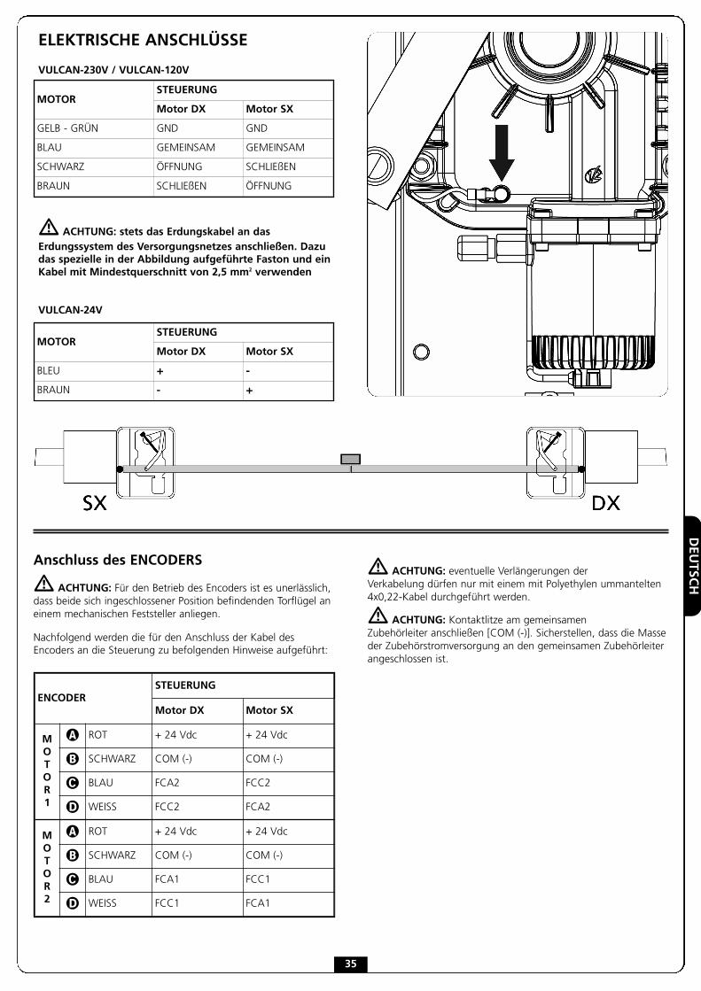
ELEKTRISCHE ANSCHLÜSSE
VULCAN-230V / VULCAN-120V
� ACHTUNG: stets das Erdungskabel an dasErdungssystem des Versorgungsnetzes anschließen. Dazudas spezielle in der Abbildung aufgeführte Faston und einKabel mit Mindestquerschnitt von 2,5 mm2 verwenden
VULCAN-24V
MOTORSTEUERUNG
Motor DX Motor SX
GELB - GRÜN GND GND
BLAU GEMEINSAM GEMEINSAM
SCHWARZ ÖFFNUNG SCHLIEßEN
BRAUN SCHLIEßEN ÖFFNUNG
MOTORSTEUERUNG
Motor DX Motor SX
BLEU + -
BRAUN - +
Anschluss des ENCODERS
� ACHTUNG: Für den Betrieb des Encoders ist es unerlässlich,dass beide sich ingeschlossener Position befindenden Torflügel aneinem mechanischen Feststeller anliegen.
Nachfolgend werden die für den Anschluss der Kabel desEncoders an die Steuerung zu befolgenden Hinweise aufgeführt:
� ACHTUNG: eventuelle Verlängerungen derVerkabelung dürfen nur mit einem mit Polyethylen ummantelten4x0,22-Kabel durchgeführt werden.
� ACHTUNG: Kontaktlitze am gemeinsamenZubehörleiter anschließen [COM (-)]. Sicherstellen, dass die Masseder Zubehörstromversorgung an den gemeinsamen Zubehörleiterangeschlossen ist.
ENCODERSTEUERUNG
Motor DX Motor SX
MOTOR1
� ROT + 24 Vdc + 24 Vdc
� SCHWARZ COM (-) COM (-)
� BLAU FCA2 FCC2
� WEISS FCC2 FCA2
MOTOR2
� ROT + 24 Vdc + 24 Vdc
� SCHWARZ COM (-) COM (-)
� BLAU FCA1 FCC1
� WEISS FCC1 FCA1
DEUTSCH
36
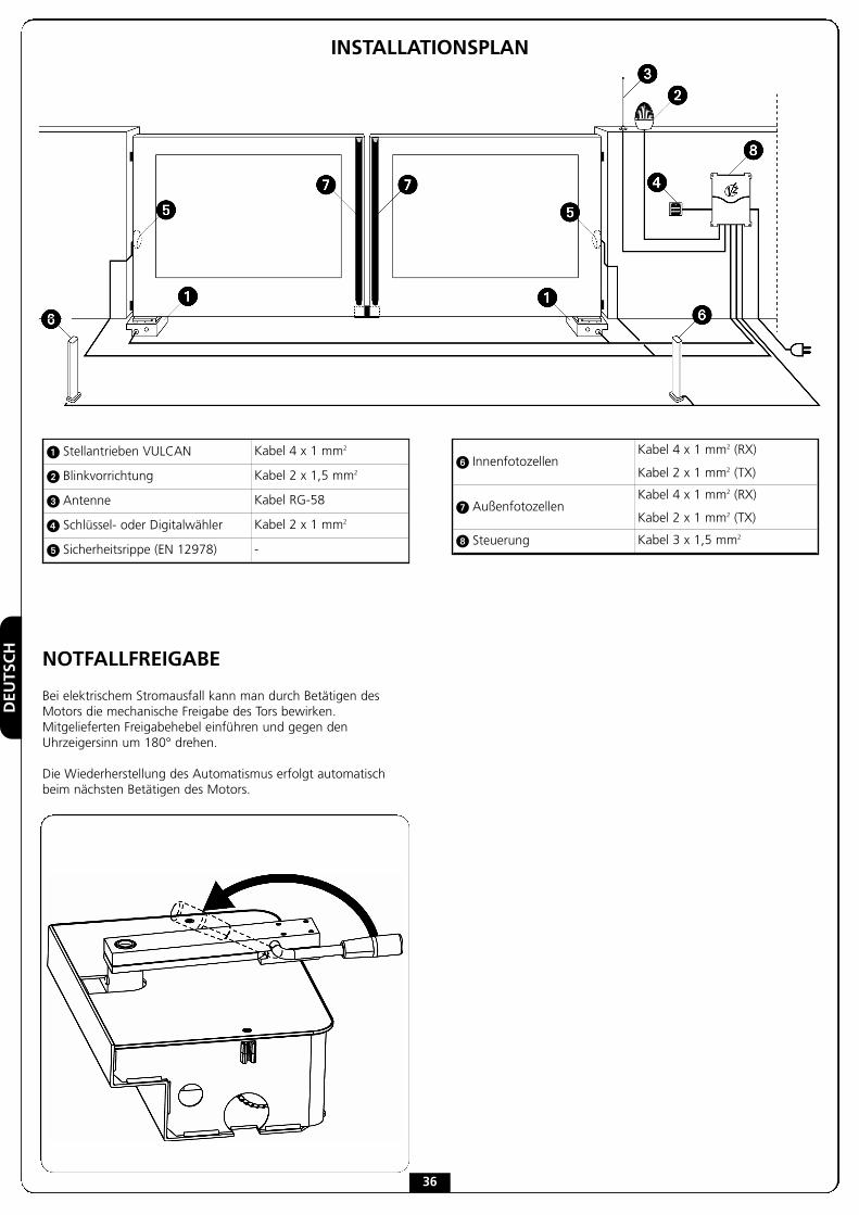
NOTFALLFREIGABE
Bei elektrischem Stromausfall kann man durch Betätigen desMotors die mechanische Freigabe des Tors bewirken.Mitgelieferten Freigabehebel einführen und gegen denUhrzeigersinn um 180° drehen.
Die Wiederherstellung des Automatismus erfolgt automatischbeim nächsten Betätigen des Motors.
INSTALLATIONSPLAN
� Stellantrieben VULCAN Kabel 4 x 1 mm2
� Blinkvorrichtung Kabel 2 x 1,5 mm2
� Antenne Kabel RG-58
� Schlüssel- oder Digitalwähler Kabel 2 x 1 mm2
� Sicherheitsrippe (EN 12978) -
� InnenfotozellenKabel 4 x 1 mm2 (RX)
Kabel 2 x 1 mm2 (TX)
� AußenfotozellenKabel 4 x 1 mm2 (RX)
Kabel 2 x 1 mm2 (TX)
Steuerung Kabel 3 x 1,5 mm2
NEDERLANDS
37
BELANGRIJKE WAARSCHUWINGENVoor technische ophelderingen of installatieproblemen beschiktV2 SPA over een assistentiedienst voor klanten die actief is tijdenskantooruren TEL. (+32) 93 80 40 20
V2 SPA behoudt zich het recht voor om zonder voorgaandekennisgeving eventuele wijzigingen aan het product aan tebrengen; het wijst bovendien elke vorm vanaansprakelijkheid af voor persoonlijk letsel of materiëleschade wegens een oneigenlijk gebruik of een foutieveinstallatie.
� Lees met aandacht de volgende handleiding met
instructies voordat u tot de installatie overgaat.
• Deze handleiding met instructies is uitsluitend bestemd voortechnisch personeel dat gekwalificeerd is op het gebied vaninstallaties van automatische systemen.
• In deze handleiding staat geen informatie die interessant ofnuttig kan zijn voor de eindgebruiker.
• Alle werkzaamheden met betrekking tot het onderhoud of deprogrammering moet uitsluitend uitgevoerd worden doorgekwalificeerd personeel.
DE AUTOMATISERING DIENT GEREALISEERD TE WORDEN INOVEREENSTEMMING MET DE HEERSENDE EUROPESENORMEN:
EN 60204-1 (Veiligheid van de machines, de elektrischeuitrusting van de machines, deel 1, algemeneregels).
EN 12445 (Veiligheid bij het gebruik van geautomatiseerdeafsluitingen, testmethodes).
EN 12453 (Veiligheid bij het gebruik van geautomatiseerdeafsluitingen, vereisten).
• De installateur moet voor de installatie van een inrichtingzorgen (bv. thermomagnetische schakelaar) die deafscheiding van alle polen van het systeem van hetvoedingsnet verzekert. De norm vereist een scheiding van decontacten van minstens 3 mm in elke pool (EN 60335-1).
• Voor de verbinding van stijve en buigzame leidingen ofkabeldoorgangen gebruikt u verbindingen die conform zijnaan beschermingsklasse IP55 of hoger.
• De installatie vereist bekwaamheden op elektrisch enmechanisch gebied en mag alleen door gekwalificeerdpersoneel uitgevoerd worden dat in staat is een verklaringvan overeenkomst van type A af te geven over de volledigeinstallatie (Machinerichtlijn 98/37/EEG, bijlage IIA).
• Men is verplicht zich aan de volgende normen inzakegeautomatiseerde afsluitingen voor voertuigen te houden:EN 12453, EN 12445, EN 12978 en eventuele nationalevoorschriften.
• Ook de elektrische installatie vóór de automatisering moetvoldoen aan de heersende normen en uitgevoerd zijnvolgens de regels van het vak.
• De instelling van de duwkracht van het hek moet gemetenworden met een daarvoor bestemd instrument in afgesteldworden in overeenstemming met de maximum waarden dietoegelaten worden door de norm EN 12453.
• Het wordt geadviseerd gebruik te maken van eennoodstopknop die geïnstalleerd wordt in de nabijheid van deautomatisering (aangesloten op de STOP-ingang van debesturingskaart) zodat het mogelijk is het hek onmiddellijk testoppen in geval van gevaar.
• De apparatuur mag niet gebruikt worden door kinderen ofdoor personen met lichamelijke of geestelijke handicapszonder dat deze over de passende kennis beschikken ofzonder toezicht door een competent persoon.
• Controleer of kinderen niet met de apparatuur spelen.
VERKLARING VAN INCORPORATIE VOORMACHINES DIE BIJNA MACHINES ZIJN(Richtlijn 2006/42/EG, Bijlage II-B)
De fabrikant V2 S.p.A., gevestigd inCorso Principi di Piemonte 65, 12035 - Racconigi (CN), Italië
verklaart op eigen verantwoording dat:
het automatisme model:VULCAN-230V, VULCAN-120V, VULCAN-24V
Serienummer en bouwjaar: die op het gegevensplaatje staanBeschrijving: Elektromechanische actuator voor hekken
- bestemd is om te worden opgenomen in een hekken, om eenmachine te vormen krachtens Richtlijn 2006/42/EG.Deze machine mag niet in dienst gesteld worden voordat zijconform verklaard is met de bepalingen van richtlijn2006/42/EG (Bijlage II-A)
- conform is met de toepasselijke essentiële vereisten van deRichtlijnen:Machinerichtlijn 2006/42/EG (Bijlage I, Hoofdstuk 1)Richtlijn laagspanning 2006/95/EGRichtlijn elektromagnetische compatibiliteit 2004/108/EG
De technische documentatie staat ter beschikking van de competenteautoriteit in navolging van een gemotiveerd verzoek dat ingediendwordt bij:V2 S.p.A., Corso Principi di Piemonte 65,12035 - Racconigi (CN), Italië.
Degene die geautoriseerd is tot het ondertekenen van deze verklaringvan incorporatie en tot het verstrekken van de technischedocumentatie is:Cosimo De FalcoRechtsgeldig vertegenwoordiger van V2 S.p.A.Racconigi, 11/01/2010

NEDERLANDS
38
HANDELINGEN VOORAF
De nieuwe serie actuatoren VULCAN is bestudeerd voor de automatische werking vanzware hekdeuren tot 800 kg met vleugels tot een lengte van 3m, afhankelijk van demodellen (zie de tabel met technische kenmerken). Voordat u tot installatie overgaat, ishet van fundamenteel belang dat uw hek vrij open en dicht gaat en moeten devolgende punten nauwkeurig gecontroleerd worden:
• Scharnieren en pennen verkeren in uitstekende staat en zijn naar behoren gesmeerd.• De beweging wordt door geen enkel obstakel belemmerd.• Er mag geen enkele wrijving met de bodem en tussen de hekvleugels geconstateerd
worden.• Uw hek moet zowel in het midden als aan de zijkanten voorzien zijn van
hekblokkeringen: deze zijn noodzakelijk voor de goede werking van het systeem.
Max.lengte hekvleugel
Max
.gew
icht
hekv
leug
el
* LET OP: indien het accessoire voor de opening van 180°(cod. 162218) geïnstalleerd wordt, is de maximumlengtevan de hekvleugel 2,5 m. bij een maximumgewicht van400 kg.
TECHNISCHE KENMERKEN 24V 120V 230V
Max.lengte hekvleugel* m
2 x 600 Kg2,5 x 500 Kg3 x 400 Kg
3,5 x 350 Kg
2 x 800 Kg2,5 x 550 Kg3 x 400 Kg
3,5 x 350 Kg
2 x 800 Kg2,5 x 550 Kg3 x 400 Kg
3,5 x 350 Kg
Voeding V / Hz 24 120 / 60 230 / 50
Absorptie bij nullast A 1 3 1,5
Maximumabsorptie A 15 4,8 2,4
Maximumvermogen W - 500 500
Nominale vermogen W 230 350 350
Condensor µF - 35 14
Openingstijd (90°) s 15 ÷ 25 15 17
Maximumkoppel N m 320 320 320
Bedrijfstemperatuur °C -20 ÷ +55 -20 ÷ +55 -20 ÷ +55
Thermische bescherming °C - 150 150
Werkcyclus % 80 30 30
Gewicht motor Kg 11,5 11 11
Beveiligingsgraad IP 67 67 67
NEDERLANDS
39
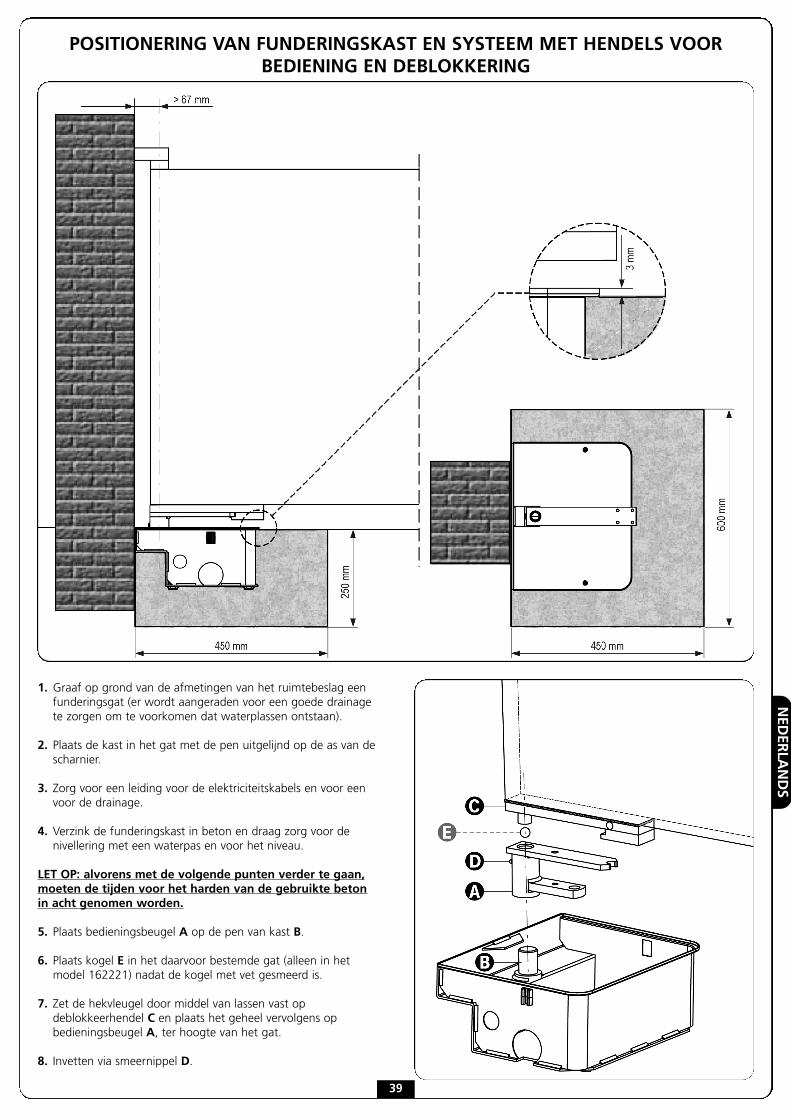
1. Graaf op grond van de afmetingen van het ruimtebeslag eenfunderingsgat (er wordt aangeraden voor een goede drainagete zorgen om te voorkomen dat waterplassen ontstaan).
2. Plaats de kast in het gat met de pen uitgelijnd op de as van descharnier.
3. Zorg voor een leiding voor de elektriciteitskabels en voor eenvoor de drainage.
4. Verzink de funderingskast in beton en draag zorg voor denivellering met een waterpas en voor het niveau.
LET OP: alvorens met de volgende punten verder te gaan,moeten de tijden voor het harden van de gebruikte betonin acht genomen worden.
5. Plaats bedieningsbeugel A op de pen van kast B.
6. Plaats kogel E in het daarvoor bestemde gat (alleen in hetmodel 162221) nadat de kogel met vet gesmeerd is.
7. Zet de hekvleugel door middel van lassen vast opdeblokkeerhendel C en plaats het geheel vervolgens opbedieningsbeugel A, ter hoogte van het gat.
8. Invetten via smeernippel D.
POSITIONERING VAN FUNDERINGSKAST EN SYSTEEM MET HENDELS VOORBEDIENING EN DEBLOKKERING

NEDERLANDS
40
INSTALLATIE VAN DE REDUCTIEMOTOR
1. Plaats de reductiemotor in de funderingskast.
2. Zet de reductiemotor vast in de funderingskast door de 4moeren vast te draaien.
3. Monteer de drijfstang van de motor op de motoras en zet deschroef vat met de bijbehorende zelfblokkerende moer.
4. Sluit de drijfstang van de motor aan op de bedieningsbeugeldoor middel van de gebogen hendel.
5. Sluit de motor aan op de stuurcentrale door de aanwijzingente volgen die in de volgende paragraaf staan.
2. Zet het hek in de stand van maximale opening, monteer deschroef van de eindschakelaar zoals de afbeelding toont enspan de schroef.
INSTALLATIE VAN DE STOPPEN VANDE EINDSCHAKELAARS
1. Zet het hek in de stand van maximale sluiting en monteer deschroef van de eindschakelaar zoals de afbeelding toont.
NEDERLANDS
41
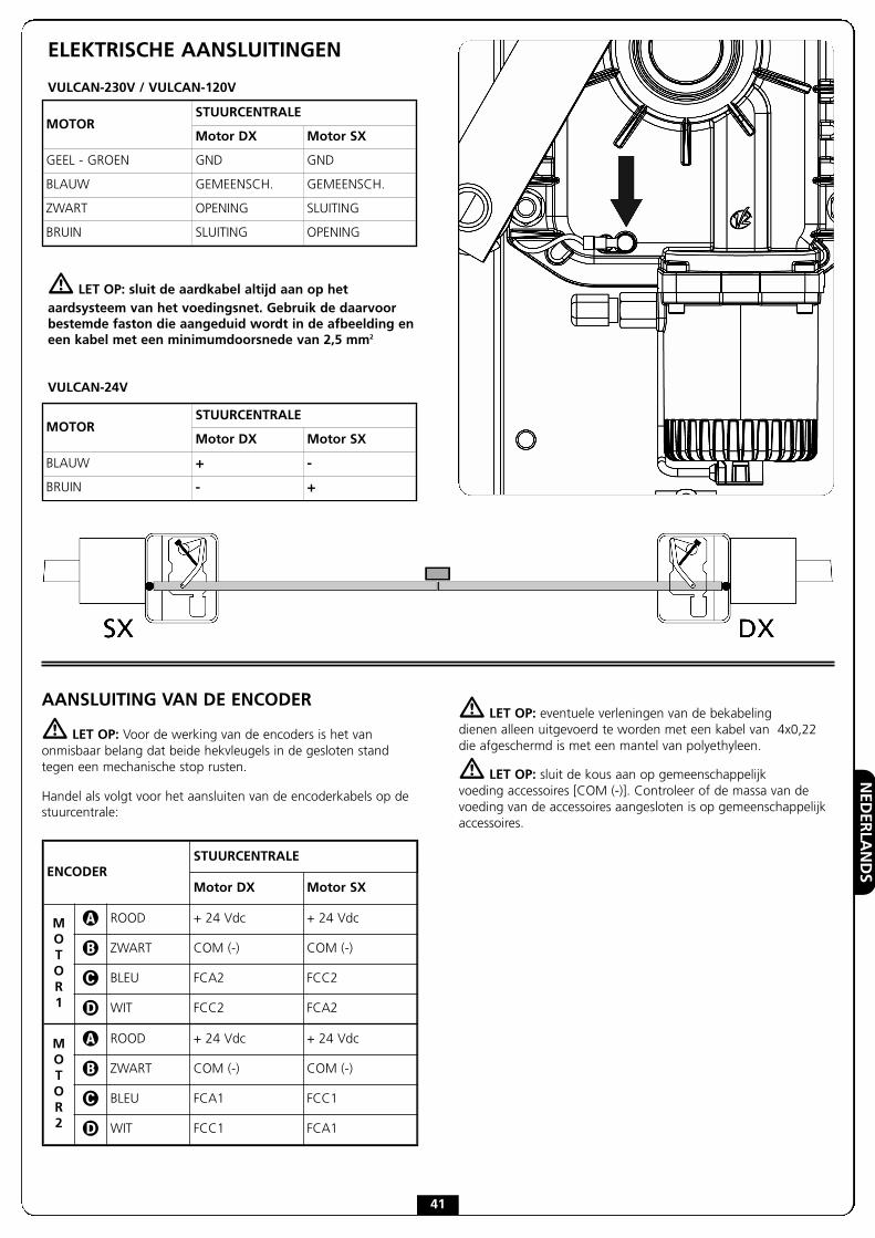
ELEKTRISCHE AANSLUITINGEN
VULCAN-230V / VULCAN-120V
� LET OP: sluit de aardkabel altijd aan op hetaardsysteem van het voedingsnet. Gebruik de daarvoorbestemde faston die aangeduid wordt in de afbeelding eneen kabel met een minimumdoorsnede van 2,5 mm2
VULCAN-24V
MOTORSTUURCENTRALE
Motor DX Motor SX
GEEL - GROEN GND GND
BLAUW GEMEENSCH. GEMEENSCH.
ZWART OPENING SLUITING
BRUIN SLUITING OPENING
MOTORSTUURCENTRALE
Motor DX Motor SX
BLAUW + -
BRUIN - +
AANSLUITING VAN DE ENCODER
� LET OP: Voor de werking van de encoders is het vanonmisbaar belang dat beide hekvleugels in de gesloten standtegen een mechanische stop rusten.
Handel als volgt voor het aansluiten van de encoderkabels op destuurcentrale:
� LET OP: eventuele verleningen van de bekabelingdienen alleen uitgevoerd te worden met een kabel van 4x0,22die afgeschermd is met een mantel van polyethyleen.
� LET OP: sluit de kous aan op gemeenschappelijkvoeding accessoires [COM (-)]. Controleer of de massa van devoeding van de accessoires aangesloten is op gemeenschappelijkaccessoires.
ENCODERSTUURCENTRALE
Motor DX Motor SX
MOTOR1
� ROOD + 24 Vdc + 24 Vdc
� ZWART COM (-) COM (-)
� BLEU FCA2 FCC2
� WIT FCC2 FCA2
MOTOR2
� ROOD + 24 Vdc + 24 Vdc
� ZWART COM (-) COM (-)
� BLEU FCA1 FCC1
� WIT FCC1 FCA1
NEDERLANDS
42
NOODDEBLOKKERING
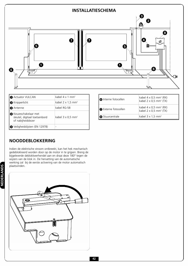
Indien de elektrische stroom ontbreekt, kan het hek mechanischgedeblokkeerd worden door op de motor in te grijpen. Breng debijgeleverde deblokkeerhendel aan en draai deze 180° tegen dewijzers van de klok in. De hervatting van de automatischewerking zal bij de eerste activering van de motor automatischplaatsvinden.
INSTALLATIESCHEMA
� Actuator VULCAN kabel 4 x 1 mm2
� Knipperlicht kabel 2 x 1,5 mm2
� Antenne kabel RG-58
� Keuzeschakelaar metsleutel, digitaal toetsenbordof nabijheidslezer
kabel 3 x 0,5 mm2
� Veiligheidslijsten (EN 12978) -
� Interne fotocellenkabel 4 x 0,5 mm2 (RX)kabel 2 x 0,5 mm2 (TX)
� Externe fotocellenkabel 4 x 0,5 mm2 (RX)kabel 2 x 0,5 mm2 (TX)
Stuurcentrale kabel 3 x 1,5 mm2


V2 S.p.A.Corso Principi di Piemonte, 65/67 - 12035 RACCONIGI (CN) ITALY
tel. +39 01 72 81 24 11 fax +39 01 72 84 050
[email protected] www.v2home.com