v 2 0001-0050 - ligeti.com 928 factory manual - volume 2.pdf · 928 table of contents volume ii 0...
TRANSCRIPT

Workshop Manual
DR. ING. h. c. F. PORSCHE Aktiengesellschaft

The Workshop Manual is only for the internal use of the Porsche Dealer Organization.
@ 1977 Dr. Ing. h.c. F. Porsche Aktiengesellschaft Sales, D-7140 Ludwigsburg
All rights reserved - Printed in Germany XX, 1988
WKD 481 621
Print No. W 42-608-126-l

List of Repair Groups
General
Repair Groups
Engine
Transmission
Chassis
BdY
Heating, Ventilation, Air Condition
Electrics
Technical Data
Maintenance, Selfdlagnosis
Engine, Crankcase Engine, Crankshaft, Pistons Engine, Cylinder Head and Valve Drive Engine, Lubrication Engine, Cooling Fuel Supply Air Flow Controlled Fuel Injection Exhaust System/Emission Controls Starter. Power Supply, Cruise Control Ignition System
Clutch, Contrds Torque Converter Manual Transmission, Controls, Case Manual Transmission, Gears, Shafts Automatic Transmission, Controls, Case Automatic Transmission, Gears, Valve Body Differential, Transaxle System
Front Wheel Suspension Rear Wheel Suspension, Axle Shaft Wheels, Tires, Alignment Antiblock System Brakes, Mechanical Brakes, Hydraulics Steering
Body-Front Section Body-Center Section Body-Rear Section LiiS Doors Hardtop Bumpers Glasses, Window Control Exterior Equipment Interior Equipment seats Seat Covers
Heater Ventilation Air Conditioner
Instruments, Fuel Gauge, Alarm System Radio Windshield Wipers and Washer Exterior Lights, lamps, Switches Interior Lights Wiring
Page 0.1
Group
03
10 13 15 17 19 20 24 26 27 28
30 32 34 35 37 38 39
40 42 44 45 46 47 48
50 51 53 55 57 61 63 64 66 68 72 74
80 85 87
90 91 92 94 96 97
Printed in Germany - XX, 1~87

928 Table of contents Volume II
0
Clutch, Controls
Technical data ................................. Torque specifications for manual transmission, gear shift, central tube Technical data ................................. Technical data (transmission type A 28.01) ................. Torque specifications ............................. Technical data ................................. Technical data (transmission type A 28.01) ................. Checking clutch play ............................. Clutch operation. ............................... Adjusting clutch spring ............................ Checking wear of clutch discs ........................ Bleeding clutch ................................ Removing and installing clutch pedal ........ ........... Removing and installing clutch spring .................... Removing and installing clutch ........................ Remvoing and installing clutch, single-disk clutch, ‘87 models onward Disassemblingandassemblingclutch (diameter-centered) ........ Disassembling and assembling clutch (dowel pin-centered) ........ Disassembling and assembling clutch (diamenter and dowel pin centered) Clutch linkage versions ............................ Ball stud versions ............................... Replacing ball stud .............................. Removing and installing clutch housing ................... Checking clutch discs ............................ Checking clutch pressure plate ....................... Checking clutch intermediate plate ..................... Overhauling clutch slave cylinder ...................... Checking clutch disc for wear ........................
Torque converter
Removing and installing torque converter 32-1
Manual transmission / controls, case
Changing transmission oil Removing and installing transmission Adjusting transmission suspension Disassembling and assembling shift linkage Disassembling and assembling transmission Disassembling and assembling upper case cover with reverse gear lock
Page
30-01 30-03 30-05 30-08 30-09 30-013 30-014 30-l 30-I 30-l 30-2 30.2a 20.2b 30-29 30-3 30-6b 30-7 30-10 30-17 30-20 30-21 30-21 30-22 30-23 30-24 30-24 30-25 30-27
34-l 34-3 34-8a 34-8~ 34-9 34-19
Table of contents Printed in Germany-XXIX, 1992
1
Volume II Table of contents 928
Manual transmission 1 Gears and shafts
Disassembling and assembling input shaft Disassembling and assembling pinion shaft Determining shim thidtness “X” Determining shim thickness “Y” Measuring Distance ‘2” between input shaft and pinion shaft Disassembling and assembling synchronizers Disassembling and assembling countershaff Hub/Gears
Automatic transmission / Controls, Case
Removing and installing transmission ..................... Removing and installing selector cable .................... Removing and installing selector lever cover frame ............. Adjusting selector cable ............................ Cable and backup light switch operation ................... Removing and installing accelerator cable .................. Adjusting throttle pressure cable ....................... NeutraVpark starting swtich .......................... Disassembling and assembling front converter housing ........... Removing and installing final drive housing ................. Removing and installing rear transmission case and rear converter housing Disassembling and assembling rear converter housing ........... Disassembling and assembling final drive housing .............. Disassemlbing and assembling transmission ................. Disassembling and assembling transmission case .............. Installing automatic transmission section ...................
Automatic Transmission / Gears, Valve Body
Checking transmission operation Troubleshooting Removing and installing valve body Replacing ATF and filter Flushing ATF cooler and lines Disassembling and assembling centrifugal governor Disassembling and assembling gear assembly Disassembling and assembling clutch K 1 Disassembling and assembling clutch K 2
Page
35-l 35-5 35-11 35-13 35-15 35-17 35-21
37-1 37-9 37-1 Oa 37-11 37-12 37-13 37-14 37-15 37-17 37-21 37.26a 37-27 37-31 37-35 37-45 37-53
38-1 38-11 38-21 38-25 38-28 38-29 38-33 38-41 38-47
2 Table of contents Printed in Germany-XXIX, 1992

928 Table of contents Volume II
0
Page
0
Differential / Transaxle System
Removing and installing differential ........................ 39-1 Disassembling and assembling differential ..................... 39-5 Adjusting pinion and ring gear ........................... 39-11 Removing and installing final drive for automatic transmission .......... 39-21 Disassembling and assembling bearing assembly for automatic transmission 39-25 Determining thickness of shims for bearing assembly ............... 39-29 Adjusting pinion and ring gear (automatic transmission) .............. 39-31 Removing and installing central tube (automatic transmission) .......... 39-41 Checking drive shaft (automatic transmission) ................... 39-49 Disassembling and assembling limited slip differential ............... 39-55 Removing and installing central tube (manual transmission) ........... 39-61 Disassembling and assembling central tube (manual transmission) ........ 39-63 Checking drive shaft (manual transmission) .................... 39-65
General
5 speed manual transmission type G 28 30-0201
Technical data 30-0203 Torque specifications 30-0205
Manual Transmission / Controls, Case
Disassembling and assembling transmission 34-201 Disassembling and assembling manual transmission (‘87 models onward) 34.214a Adjusting shift forks 34-215 Adjusting shifts 34-217 Adjusting gearshift (‘86 models onward) 34-218a Adjusting gearshift (‘87 models onward) 34-218~ Disassembling and assembling upper transmission cover with reverse gear arresi 34-219 Disassembling and assembling upper transmission cover (‘87 models onward) 34-220 Dismantling and assembling housing cover with oil pump 34-221 Replacing O-ring for spray tube (type G28/57) 34-223
Manual Transmission / Gears and Shafts
Disassembling and assembling drive shaft. .................... 35-201 Disassembling and assembling drive pinion .................... 35-205 Disassembling and assembling countershaft. ................... 35-215 Disassembling and assembling layshaff (‘87 models onward) ........... 35-219
Table of contents
Printed in Germany - XXXV, 1996
3

Volume II Table of contents 928
Differential / Transaxle System Page
Removing and installing differential . . 39-201 Measuring the plate wear on the proportional-slip differential 39-206a Removing and installing the proportional-slip differential 39-206c Bleeding hydraulics of Porsche controlled slip differential (PSD) 39-2061 Disassembling and assembling differential 39-207 Limited-slip differential, disassembling and assembling (40% lock-up) 39.212a Dismantling and assembling the proportional-slip differential 39.212i Dismantling and assembling lim. slip. differential with Valeo friction discs 39-212s Adjusting pinion and ring gear. 39-213 Determining thickness of shim S5 39-215 Drive shafi and ring gear, adjusting 39-217 Adjusting and drive pinion and ring gear 39-219 Adjusting drive pinion and ring gear. 39-221 Adjusting drive pinion and ring gear. 39-225
PSD diagnosis /Troubleshooting: beginning with supplement 35, pages see voume Ill.
4 Table of contents
Printed In Germany - XXXV, 1996
928 General 30
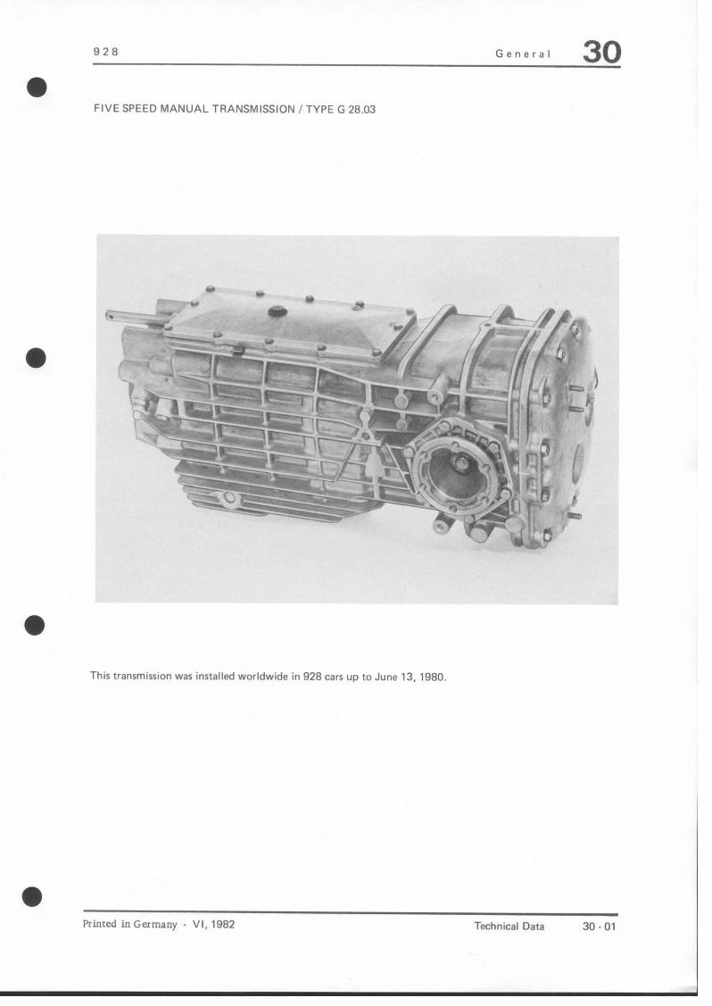
a FIVE SPEED MANUAL TRANSMISSION /TYPE G 28.03
a
a
This transmission was installed worldwide in 928 cars UP to June 13, 1980
a
Primed in Germany VI, 1982 Technical Data 30.01

30 General 928
a
FIVE SPEED MANUAL TRANSMISSION /TYPE G 28.05
Installed in 928 cars beginning with 1981 models (June 1980)
This transmission is similar in design and repairing procedures to transmission type G 28.03, but has the following modifications.
1. Transmission moved forward by 30 mm.
2. Drive shaft longer.
3. Transmission case with modified ribs and hexagon head bolts instead of studs for the rear transmission cover.
4. Split needle bearings for loose gears.
5. Light alloy selector forks.
6. Modified pinion/ring gear (R = 70.70 mm).
30.02 Technical Data Printed in Germany

928 General 30
FIVE SPEED MANUAL TRANSMISSION /TYPE G 28.08
i L .’
a
t 3 C’ $ C
a
Transmission Type Installed In
G 28.08 928 S - 1983 Model
This transmission is similar in design and repairing procedures to transmission type G 28.05, but the ratios are different (see page 30 - 06).
Printed in Germany VII, 1983

928 General 30 a
TORQUE SPECIFICATIONS FOR MANUAL TRANSMISSION, GEAR SHIFT, CENTRAL TUBE
Location Description Threads/Pitch Material Torque Nm (ftlb)
Central tube/transmission
Pinion bearing assembly
Bearing cap/ transmission case
Bolt M 10x 1.5 10.9 58 (42)
Nut M 42 x 1.5 15CrN i6 280 (202)
Bolt MEx1.25 10.9 30 (22)
Plug/locks
Upper covert transmission case
Reverse gear deflector/ upper cwer
Plug M 12x 1.5 5.8 19 (14)
Bolt M6xl 8.8 9 (7) 12.9 16 (12)
Bolt M6xl 8.8 9 (7)
Ring gear Bolt M 12 x 1.25 12.9 165 (119)
Side covert Bolt M8x 1.25 8.8 22 (16) transmission case
Rear cover/ Nut MEx1.25 8.8 22 (161 transmission case
Oil filler and drain plugs
Clamping sleeve/ drive shaft
Backup light switch
Joint flange/ transmission outlet
Plug
Bolt
Switch
Bolt
M24x1.5 22 (16)
M 10x 1.5 8.8 48 (35) 12.9 80 (58)
MlEx1.5 22 (16)
MlOx1.5 8.8 43 (31)
Bearing/internal selector rod
Bolt MEx1.25 8.8 15 (11)
Transmission mount/ Bolt MlZx1.5 8.8 85 (61) transmission case
a
Printed in Germany VI, 1982 Tightening Torques 30.03

30 General 928
Location Description Threads/Pitch Material Torque Nm (ftlb)
Central tube/ clutch housing
Bolt M 10x 1.5 8.8 43 (31)
Selector rod/ bearing any. Iselector rod coupling)
Bolt M 8 x 1.25 25 (18)
Ball socket/ guide tube
Nut BM 10 25 I181
Guide tube bracket to body or central tube
Nut M6xl 9 (7)
a
a
a
a
30 04 Tightening Torques Printed in Germany

a
928 General 30
General data Manual transmission type G 28.03 and 28.05
countershaft
Ratios *
2nd gear
3rd gear
5th gear
Reserve gear
Final drive
Final drive ratio
Transmission oil
Drive pinion without hypold offset
12 : 33 i = 2.7500 up to Jan. 13, 1981 11 :30 i = 2.7272 since Jan. 14, 1981
Multigrade gear lube SAE 75 W 90 API Classification GL 5 (or MIL-L-2105 B)
Oil capacity approx. 3.8 liters
* 21 = Number of teeth on first gear meshed for selected gear
22 = Number of teeth on second gear meshed for selected gear
:z = Gear ratio
‘VW = Countershaft ratio
a Printed in Germany VII, ,983 Technical Data 30.05

30 General
General Data Manual Transmission Type G 28.08
Design I Darect transmission with countershaft
Ratios * Z1
1st gear 17
2nd gear 22 38 1.7272 1.650 2.8498
3rd gear 26 32 1.2307 1.650 2.0306
4th gear 29 27 0.9310 1.650 1.5361
5th gear / direct direct 1 .oooo direct
Reverse gear
44
(30, 50
‘2 z* :z,
‘vor 33 : 20
b ivor
2.5882 1.650 4.2705
2.2727 1.650
1 .oooo
3.7499
Final drive Drive pinion without hypoid offset
-
Final drive ratio
Transmission oil
15:34 i=2.2666
Multigrade gear lube SAE 75 W 90 API Classification GL 5 (or MIL-L 2105 BI
Oil capacity approx. 3.8 liters
I
- z, = Number of teeth on first gear meshed for selected gear
Z2 = Number of teeth on second gear meshed for selected geal
5 = Gear ratio
iVor = Countershaft ratio
a
a
a
a
30 06 Technical Data VII, 1983 Printed in Germany

928 General 30
General Data
Design
Pressure plate 197811979 models
from 1980 models
Spring pressure 197811979 models from 1980 models from 1984 models
Clutch disc (flywheel end)
Clutch disc (clutch end)
TORQUE SPECIFICATIONS FOR CLUTCH
Location Description Threads Material
Starter ringiinterm. plate Bolt M7xl 8.8
Guide tube/clutch housing Bolt M6xl 8.8
Clutch slave cylinder Bolt MEx1.25 8.8
Clamp/input shafts Bolt M 10x 1.5 8.8
12.9
Clutch housing/central tube Bolt M 10x 1.5 8.8
Engine/clutch housing Bolt M 12 x 1.5
Clutch housing/cover Bolt M8x 1.25
Clutch/flywheel Bolt MEx1.25
8.8
8.8
8.8
Ball stud/clutch housing Ball stud
Flywheel/crankshaft Bolt
M6 ME
M 10 x 1.25
Clutch
Double disc, dry clutch with diaphragm springs, pulled version. engine end arrangement. hydraulically operated
MFZ Z/215 KS ph (200 mm dia.; as spare part after depletion of stocks) MFZ Z/ZOO KS ph
5000to5700 N U124to1281 lb) 5400 to 5900 N (1214 to 1326 lb) 5600 to 6200 N 200 mm dia.
200 mm dia.
Torque Nm (ftlbl
,6:5)
22 116)
48 (35) 80
(58)
,Z,
77 (56)
22 116)
10 (7) 23 (17)
90+5 (70 + 4)
a
Printed in Germany VIII, 1984 Technical Data 30 -06a

928 General 30
THREE SPEED AUTOMATIC TRANSMISSION
3 21
1 - Front converter housing 2 - Rear converter housing 3 -Automatic transmission 4 - Rear transmission case 5 - Final drive
Transm. TWX 1 Installed In
A 22.01 928 -from 1980 models
A 22.02 928 - 19780979 models
Printed in Germany Vi, 1982 Technical Data 30.07

30 General 928
FOUR SPEED AUTOMATICTRANSMISSION
1 - Front converter housing
2 -Automatic transmission
3 - Final drive
Transmission Type I Installed In
A 28.01 928 S - standard from 1983 models
30.08 Technical Data (Transmission Type A 28.01)
VII, 1983 Printed in Germany
928 General 30
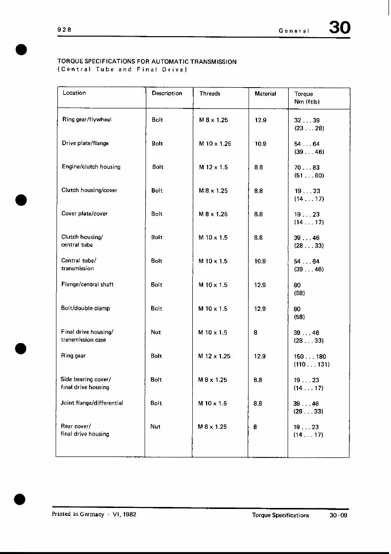
TORQUE SPECIFICATIONS FOR AUTOMATIC TRANSMISSION (Central Tube and Final Drive)
Location Description Threads Material Torque Nm (ftlb)
Ring gear/flywheel Bolt M8x 1.25 12.9 32 .39 (23.. .28)
Drive plate/flange Bolt M 10x 1.25 10.9 54...64 (39 ,461
Engine/clutch housing Bolt M 12x 1.5 8.8 70 .83 (51 .60)
Clutch housing/cover Bolt M8x1.25 8.8 19. 23 (14.. .17)
Cover plate/cover Bolt M8x1.25 8.8 19...23 (14.. .17)
Clutch housing/ Bolt MlOxl.5 8.8 39 .46
central tube (28 33)
Central tube/ Bolt M 10x 1.5 10.9 54 .64 transmission (39...461
Flange/central shaft Bolt M 10x 1.5 12.9 80
(58)
Bolt/double clamp Bolt M 10x 1.5 12.9 80
(58)
Final drive housing/ Nut MlOx1.5 8 39...46 transmission case (28 .33)
Ring gear Bolt M 12x 1.25 12.9 150...180 (110.. 131)
Side bearing cover/ final drive housing
Joint flange/differential
Bolt M8x 1.25 8.8 19...23 (14...17)
Bolt M 10x 1.5 8.8 39 .46 (28...33)
Rear cowl Nut MEx1.25 8 19...23 final drive housing (14.. .17)
Printed in Germany VI, 1982 Torque Specifications 30-09

30 General 928
TORQUE SPECIFICATIONS FOR AUTOMATIC TRANSMISSION (Central Tube and Final Drive)
Location Description Threads Material Torque Nm (ftlb)
Bearing assembly/ rear transmission case
Pinion/output shaft Transmission without fixed governor (see page 39 .24 a)
Bolt M8x1.25 10.9 27...32 (20 . ..23)
Nut M 26 x 1.5 L 35 v 200 . ..240 (145.. ,174)
Pinion/output shaft Transmission with fixed governor (see page 39 24 a)
Nut M 26 x 1.5 L 35 v 280 (202)
30.010 Torque Specifications Printed In Germany

928 General 30
General Data
Design
Ratios
1st gear 2nd gear 3rd gear (D) Reverse (RI
Final drive
Final drive ratio
Stall speed
Automatic Transmission Type A 22.01 and A 22.02
Fully automatic, 3.speed, planetary gear transmission
2.306 1.460 1.000 1.836
Pinion without hypoid offset
1 Z/33 2.750
2350 + 200 rpm - 197811979 mod. 2470 + 200 rpm -from 1980 models
Converter ratio
Final drive oil capacity
2.00
Approx. 2 liters/Z.1 US qt of hypoid gear lube API classification GL 5 (MIL-L 2105 B) SAE 90
Automatic transmission and converter oil capacity
Approx. 6 litersl6.3 US qt total oil capacity. Approx. 5.5 litersl5.8 US qt oil change capacity including converter; ATF Dexron B
l Printed in Germany VI, 1982 Technical Data 30.013

30 I General 928
General data
Design
Ratios:
1st gear 3.6760 2nd gear 2.4120 3rd gear 1.4360 4th gear 1 .oooo
Reverse geal 5.1390
Final drive
Final drive ratio
Stall speed
Converter ratio
Oil capacity - final drive
Oil capacity -automatic transmission + converter
Automatic transmission Type A 28.01
Fully automatic four speed planetary gear transmission
Drive pinion without hypoid offset
15:33 i = 2.2000
2200. 2600 rpm
i = 2.12
approx. 3 liters of hypoid gear lube SAE 90 APL Classification GL 5 (MIL-L-2105 B)
approx. 8 liters total initial amount; approx. 6.2 liters for change including torque converter; ATF Dexron B sperm whale oil free
a 30.014 Technical Data VII. 1983 Printed in Germany
(Transmission Type A 28.01 I

928 Clutch, Controls 30
Clutch operation
Checking clutch free travel Adjusting the clutch spring
Due to the fact that the clutch is fitted with an automatic hydraulic adjuster, the clutch free travel cannot be checked at the clutch pedal. To ensure proper operation of the clutch. how- ever, the pushrod must be adjusted correctly,
Adjusting the pushrod
Adjust for zero clearance with the pushrod (1) disengaged to allow the pushrod to be pushed over the pin (2) without any load being present. Then preload the pushrod by rotating by one turn and lock with nut (3).
To boost foot pressure, a boost spring is fitted to reduce the pedal force required. To achieve this effect, the boost spring must be preloaded sufficiently. When measuring from the inside of the spring cup to the center of the mounting pin, dimen- sion A must be 43 mm for vehicles up to MY ‘91 and 21 mm for vehicles as of MY ‘92 with the clutch engaged (clutch pedal at end stop). If required, correct setting by rotating the wing nut or the hexagon nut, respectively.
Clutch operation
Printed in Germany - XXVII, 1991
30 - 1

30 Clutch/Controls 928
CHECKING WEAR OF CLUTCH DISCS
The amount of clutch disc wear will not be indicated at the clutch pedal because of the automatic hydraulic clutch adjustment.
Check for wear according to the following procedures.
1. Remove plug from inspection hole.
2. Visually inspect position of release lever. The wear limit has been reached for cars up to and including 1982 models when front edge of lever just appears in inspec- tion hole. Beginning with 1983 models there were changes in starter installation and inspection hole location. The wear limit has been reached when front edge of lever reaches end of inspection hole.
A = Wear travel of clutch 17.4 mm B = Operating travel 17.4 mm
0 30 2 Checking Wear of Clutch Discs VIII, 1984 Printed in Germanv
928 Clutch. Controls 30 0
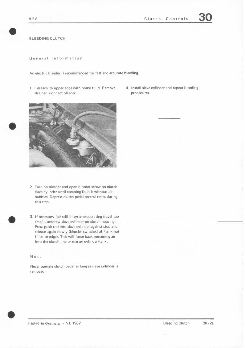
BLEEDING CLUTCH
General Information
An electric bleeder is recommended for fast and accurate bleeding
1. Fill tank to upper edge with brake fluid. Remove 4. Install slave cylinder and repeat bleeding strainer. Connect bleeder. procedures.
I r
2. Turn on bleeder and open bleeder screw on clutch slave cylinder until escaping fluid is without air bubbles. Depress clutch pedal several times during this step.
3. If necessary (air still in system/operating travel too
Press push rod into slave cylinder against stop and release again slowly (bleeder switched off/tank not filled to edge). This will force back remaining air into the clutch line or master cylinder/tank.
Note
Never operate clutch pedal as long as slave cylinder is removed.
a Printed in Germany VI. 1982 Bleeding Clutch 30.2a
30 Clutch, Controls 928
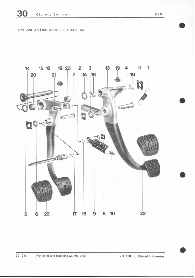
REMOVING AND INSTALLING CLUTCH PEDAL
2F :’ %.;, ’ ‘\.
‘..
3 13 19 1 11 1
16
30.2b Removing and Installing Clutch Pedal VII. 1983 Printed in Germanv

928 Clutch, Controls 30
Note When: Special NO. Description Qty. Removing Installing Instructions
1 Return spring 1 Position correctly The return spring (from 1982 models on) can also be used in older cars
2 Retainer 1 Replace if necessary
3 Washer 1
4 Shaft 1 Coat with multi- purpose grease
5 Retainer 1 Replace if necessary
6 Washer 1
7 Shaft 1 Coat with multi- purpose grease
8 Retainer 1 Replace if “MXSSXy
9 Washer 1
10 Guide rod/ 1 Insert assembly clutch power spring wire (see page assy. 30.2.~)
11 Retainer 1 Replace if necessary
12 Bearing shaft 1 Install with multi-purpose grease. Can only be pushed in fully when surfaces on bearing shaft and console are aligned.
13 Brake pedal 1 Spacers (pedal adjurtmentl are available
Printed in Germany VII, 1983 Removing and Installing Clutch Pedal 30.2~

30 Clutch, Controls 928
Note When : Special NO. Description Qty. Removing Installing Instructions
14 Washer 2 In cars with one 1 mm thick 2 mm thick washer LHD cars after 1982 between two models (altered clutch pedals) two 1 mm pedal) thick washers may
be installed (see Washer (11 page 30 .2 bl 2 mm thick between two pedals
15 Clutch pedal 1 Spacers (pedal adjustment) are available
16 Bushing 2 Replace if necessary
17 Bushing 1 Replace if “MXSSXy
18 Bushing 1 Replace if necessary
19 Stop (pad1 2 Replace if necessary
20 Needle bearing 2 Press in flush, pack with all- purpose grease
21 Shaft 1 Press out, Press in against using a suitable stop sleeve for support
22 Pedal rubber cover 2 Replace if necessary
a
30.2d Removing and Installing Clutch Pedal Printed in Germany
928 Clutch, Controls 30
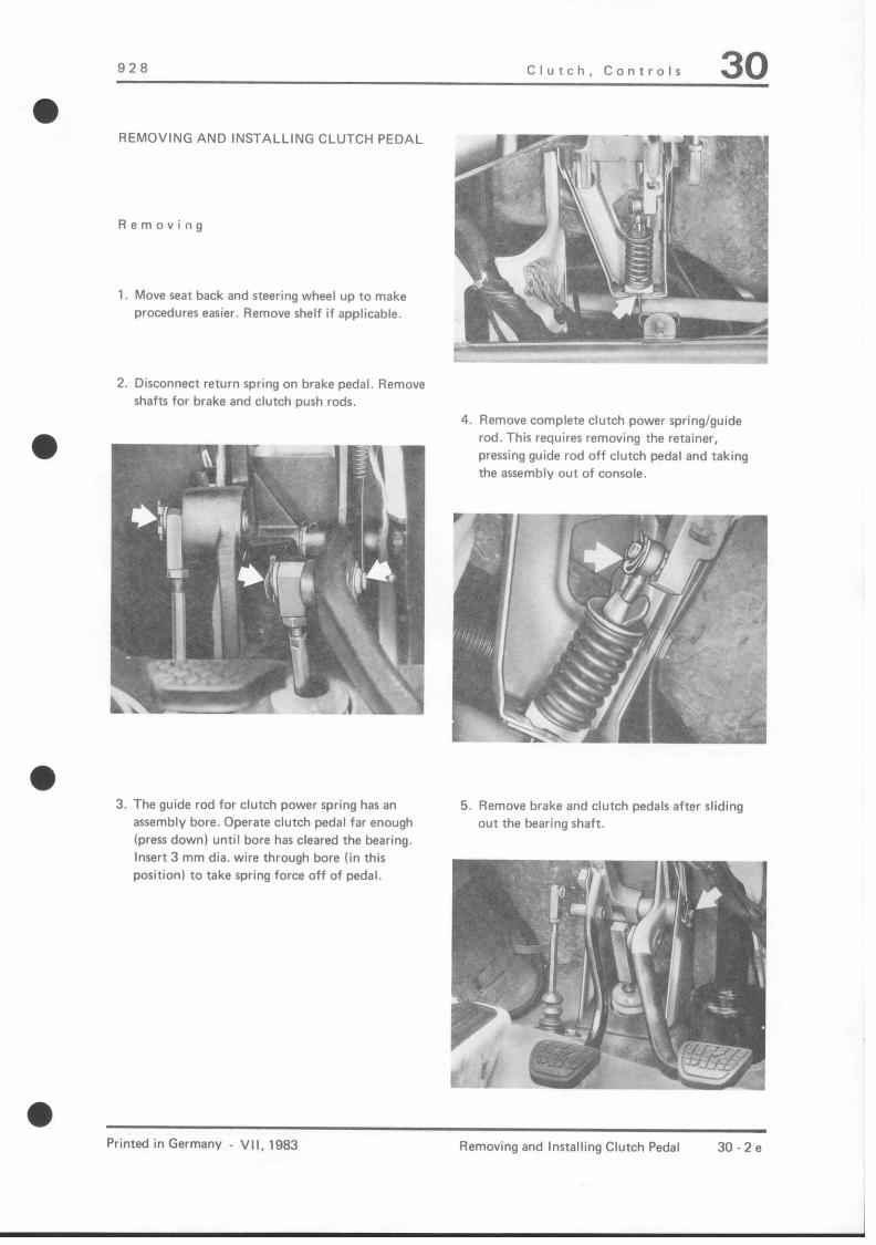
REMOVING AND INSTALLING CLUTCH PEDAL
Removing
1. Move seat back and steering wheel up to make procedures easier. Remove shelf if applicable.
2. Disconnect return spring on brake pedal. Remove shafts for brake and clutch push rods.
mp -w-y 7 ‘, ,._.: ‘”
3. The guide rod for clutch power spring has an assembly bore. Operate clutch pedal far enough (press down) until bore has cleared the bearing. Insert 3 mm dia. wire through bore (in this positionl to take spring force off of pedal.
4. Remove complete clutch power spring/guide rod. This requires removing the retainer, pressing guide rod off clutch pedal and taking the assembly out of console.
5. Remove brake and clutch pedals after sliding out the bearing shaft.
a Printed in Germany VII, 1983 Removing and Installing Clutch Pedal 30.2e

30 Clutch, Controls 928
Installing
1. Check needle bearing, bearing shaft, retainers, stops, all sleeves and shafts, replacing if necessary. Coat all bearing and sliding surfaces with a multi- purpose grease.
2. Install pedals
Note:
Bearing shaft can only be pushed in fully, if surfaces on bearing shaft and console are aligned
3. Place complete clutch power spring/guide rod in console and mount on clutch lever.
4. Take assembly wire out of guide rod and move clutch pedal to final stop.
5. Mount clutch and brake push rod on pedals. Connect return spring for brake pedal. Check push rod play, correcting if necessary. See pages 30 1 and 46 9.
l 30.2f Removing and Installing Clutch Pedal Printed in Germany

928 Clutch, Controls 30
REMOVING AND INSTALLING CLUTCH SPRING
Removing
1. Move seat back and steering wheel up to make procedures easier. Remove tray if applicable.
2. Remove shaft for clutch push rod
3. The guide rod for clutch power spring has an assembly bore. Operate clutch pedal enough (press down) until bore has cleared the bearing. Insert 3 mm dia. wire through bore in this position.
4. Remove complete clutch power spring/guide rod. This requires removing the retainer. pressing guide rod off of clutch pedal and taking out of COnSOle.
5. Release clutch power spring by turning winged nut as far as possible.
6. Remove piece of wire and take parts off of guide rod.
0 Printed in Germany - VII, 1983 Removing and Installing Clutch Spring 30-29

30 Clutch, Controls 928
Installing
1. Slide clutch power spring and pertinent parts on to guide rod. Insert piece of wire.
4543 ?
l 6 1 KLl, efl’
L I.4
A Assembly bore
1 Bearing
2 Clutch power spring
1
3. Install adjusted complete part in car and mount on clutch pedal.
4. Take piece of wire out of guide rod and ad- just clutch pedal to final position.
5. Mount clutch push rod on pedal. Check push rod adjustment and correct if required.
3 Spring retainer
4 Washer
5 Winged nut
6 Guide rod
7 Bearing sleeve
2. Adjust clutch power spring. Distance A be- tween inside of spring retainer and center of bearing shafl should be 43 mm*. If neces- sary, correct by turning the winged nut.
* As of MY ‘92. dimension A is 21 mm. At the same time, the parts listed under #em 1 have been modified.
30 - 2h Removing and installing Clutch Spring Printed in Germany - XXVII, 1991
928 Clutch/Controls 30 l
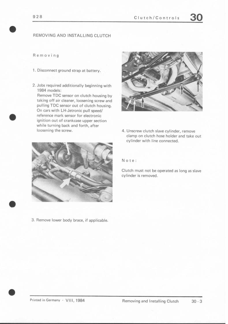
REMOVING AND INSTALLING CLUTCH
Removing
1. Disconnect ground strap at battery.
2. Jobs required additionally beginning with 1984 models: Remove TDC sensor on clutch housing by taking off air cleaner, loosening screw and pulling TDC sensor out of clutch housing, On cars with LH-Jetronic pull speed/ reference mark sensor for electronic ignition out of crankcase upper section while turning back and forth, after loosening the screw.
3. Remove lower body brace, if applicable.
4. Unscrew clutch slave cylinder, remove clamp on clutch hose holder and take out cylinder with line connected.
Note:
Clutch must not be operated as long as slave cylinder is removed.
Printed in Germany - VIII, 1984 Removing and Installing Clutch 30 - 3

30 Clutch/Controls 928
5. a) Before 1983 Models Remove cover for clutch housing with starter and suspend from stabilizer. If applrcable, also remove converter (modified shaoe).
v- WE “fl’
!
%p.gj$r~~ --
\ ./’ /“t \\ .
5. b) Since 1983 Models (Modified Starter Installation) Remove starter or loosen starter and suspend it from car. Take off clutch housing cover. If applicable, also remove catalytic converter.
6. Remove coupling screws and push back coupling on central shaft II. In case of long coupling, remove plug from central tube to unscrew rear bolt.
7. Remove release bearing sleeve mounting bolts and push sleeve toward flywheel.
8. Mark position of pressure plate, inter- mediate plate and flywheel in relation to each other for installation later. For dowel pin centered clutches drive the cylindrical pins in direction of pressure plate with a punch far enough so that they are beyond the centering bore of the flywheel. Check visually at opening of intermediate plate (arrow).
Beginning with 1984 models one of the three centering pins is stepped (6 mm dia. in area of intermediate ring/pressure plate and 8 mm dia. in flywheel). Consequently the intermediate ring can only be installed in a certain position to the flywheel (see intermediate ring on page30-16a). Remove stepped centering pin (large bore in flywheel) completely. This is only possible in direction of the flywheel. Drive the other two centering pins in direction of pressure plate as described above, until they are beyond the centering bore of the flywheel (do not remove completely).
0 30-4 Removing and Installing Clutch Printed in Germanv

928 Clutch/Controls 30 a
a Beginning with 1984 models
‘“9, _,
removal will be easier by using 4 mm thick wire brackets (locally made) underneath the bolt heads before loosening the mounting bolts (less force required/brackets bevelled). In addition, it will not be necessary to unscrew the mounting bolts in steps of 1 to 1 l/2 turns. Also refer to point 6 on page 30 - 6 and point 2 on page 30 - 17.
10. Push back entire clutch (pressure plate, intermediate ring with starter gear ring, both clutch discs, release lever, release bearing sleeve, central shaft I) and remove downward.
9. Unscrew the clutch mounting bolts one after the other by 1 to 1 l/2 turns until pressure is removed from the pressure plate. Disconnect release lever at ball stud, by pushing the release lever down toward the flywheel. Now remove the mounting bolts.
2. Prior to installation push intermediate ring at the three adjusting elements in direction of the release bearing. If applicable, pre-load clutch pressure plate (see page 30 - 17).
Printed in Germany - VI I I, 1984 Removing and Installing Clutch 30 - 5
Installing
1. Check and, if necessary, replace clutch parts prior to installation. Also refer to “Disassembling and Assembling Clutch”, “Clutch Control Ball Stud Versions” and “Checking Discs, Pressure Plate and Intermediate Plate”.

30 Clutch/Controls 928
3. Assemble clutch (hubs of discs face release bearing, correct location of centering pins from intermediate ring for dowel pin centered clutches - see page 30 - 18). Guide clutch into clutch housing and center discs with drive shaft in grooved ball bearings of crankshaft.
Note:
The discs are different. Disc I (sometimes marked with white paint dot) is between flywheel and intermediate ring. Disc II (larger liner springs or longer hub) is between pressure plate and intermediate ring (see page 30 14). When installing discs on short central shaft make sure residual unbalance sides (yellow arrow/black side) are offset 180” opposite each other.
4. Note marks when installing pressure plate, intermediate ring and flywheel. Guide centering pins of a dowel pin centered clutch into the flywheel. Beginning with 1984 models guide in far enough that correct position of inter- mediate ring (missing centering pin) to flywheel (large bore) is given. Insert mounting bolts.
5. On cars from 1984 models on align stepped centering pin with centering bore in intermediate ring and drive it in from the flywheel side.
6. Screw in clutch mounting bolts uniformly until the clutch is held tight. Make sure that central shaft I moves easily. Then remove the clips from underneath the pressure plate bolt heads. If applicable (since 1984 models), drive stepped centering pin further against stop.
a
30 - 6 Removing and Installing Clutch Printed in Germany
928 Clutch/Controls 30
Note:
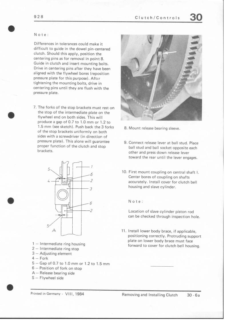
Differences in tolerances could make it difficult to guide in the dowel pin-centered clutch. Should this apply, position the centering pins as for removal in point 8. Guide in clutch and insert mounting bolts. Drive in centering pins after they have been aligned with the flywheel bores (reposition pressure plate for this purpose). After tightening the mounting bolts, drive in centering pins until they are flush with the pressure plate.
7. The forks of the stop brackets must rest on the stop of the intermediate plate on the flywheel end on both sides. This will produce a gap of 0.7 to 1 .O mm or 1.2 to 1.5 mm (see sketch). Push back the 3 forks of the stop brackets uniformly on both sides with a screwdriver (in direction of pressure plate). This alone will guarantee proper function of the clutch and stop brackets.
1 - Intermediate ring housing 2 - Intermediate ring stop 3 - Adjusting element 4 - Fork 5 - Gap of 0.7 to 1 .O mm or 1.2 to 1.5 mm 6 - Position of fork on stop A - Release bearing side S - Flywheel side
8. Mount release bearing sleeve.
9. Connect release lever at ball stud. Place ball stud and ball socket opposite each other and press down release lever toward the rear until the lever engages.
10. First mount coupling on central shaft I, Center bores of coupling on shafts accurately. Install cover for clutch bell housing and slave cylinder.
Note:
Location of slave cylinder piston rod can be checked through inspection hole.
11. Install lower body brace, if applicable, positioning correctly. Protruding support plate on lower body brace must face forward to cover for clutch bell housing.
Printed in Germany VI I I, 1984 Removing and Installing Clutch 30.6a

30 Clutch, Controls 928
REMOVING AND INSTALLING SINGLE-DISK CLUTCH
'87 MODELS ONWARD
ENGINE TYPE M 28 .41
Removing
l.Detach ground lead from battery.
Z.Remove complete lower engine guard.
3.Unbolt clutch actuating cylinder, disconnect clutch hose holder from oil pan and allow cylinder to dangle with line connected.
Note:
Never depress the clutch with actuating cylinder disconnected.
4.Unbolt starter motor, withdraw and leave on bracket.
5.Unbolt exhaust flanges on left and right manifolds and detach air injector.
6.Remove cover from clutch housing.
7.Remove clamping sleeve cap screws and push sleeve back along central shaft II. If long clamping sleeve is fitted, remove plug in central tube to permit removal of the rear screw.
8.Remove securing screws for guide tube and push guide tube toward flywheel.
9.Disengage release lever from ball joint by pressing lever down toward flywheel.
lO.Fabricate three sheet-metal angles (2 tmn thick), if no angles are installed.
Note:
These improvised angles are used to tension and position the genuine Porsche spare parts.
30 - 6b Removing and Installing Clutch, Single-Disk Clutch,'87 Models Onward
Printed in Germany - XVI,1987

Clutch, ODeration
0 11 Insert angle in notch of pressure plate and
slacken mounting boits. Drive centering pins out of flywheel toward pressure plate.
c. -- -
1
1
12. Remove mounting bolts unifonly one after the other and remove pressure plate from bottom, complete with release lever, guide tube, driven plate and central shaft 1.
Note
1. The straight pins for the TDC sensor must point downward to permit removal of the complete clutch (risk of damage).
2. Lubricant “Optimoly HT’ has been replaced by “Optimoly Olista Longtime 3EP”. To be used on clamping sleeve, drive shaft, clutch release lever, guide tube and clutch release bearing.
3. As of Model ‘93, engine type M 28.49.928 GTS, the clutch release bear- ing is fitted with a plastic guide sleeve. Guide tube and guide sleeve are fitted with- out grease and must not be greased
elther when repairs are made in this area.
Installing
1. Install pre-loaded pressure plate with driven plate in clutch housing, center drive plate with central shaft 1 in deep-groove ball bear ing of crankshafl and tighten mounting bolts 1 to i/2 turns.
2. Fii guide tube. Make sure that the guide tube is seated correctly in the correspon- ding cutout in the clutch bell housing and that the entire contact surface of guide tube and clutch bell housing is in contact.
3. Engage release lever by placing ball and socket opposite each other and pressing re- lease lever down and back until t is feit to engage.
4. Attach calmping sleeve to central shaft 1 first. Align holes of clamping sleeve on shafts.
5. Uniformly tighten mounting bolts of presure plate. Tightening torque 22 Nm (16 fflb) remove angles (3 of).
0 Rem. and lntalllng clutch single-plate clutch as of MY’87 30 - 6c Printed in Germany - XXXI, 1993

30 Clutch, Operation 928
6. Check centering pins. Using a depth gauge, measure from the rear of the flywheel (en- gine side) through the bore to the centering pin (approx. 4 mm).
7. Insert slave cylinder into clutch bell housing and tighten cover. Then fit slave cylinder into place.
30-66 Removing and installing clutch, single-plate clutch ae of MY ‘87 Printed in Germany - XXXI, 1993

928 Clutch, Controls 30
iii:
~
Ar
‘,I \
Printed inGermany - IV. lq80 Disassembling and Assembling Clutch (Diameter-Centered)
30 - I

30 Clutch. Controls 928
.-
I -
X
x
L
Note When: Special
\lo. Description Qty. Removing Installing Instructions
1 Bolt 2 Tighten to specified torque
2 Washer 2 Replace if necessary
3 Guide tube 1 Coat sliding surface for release bearing with MoS,
4 Short drive shaft 1 Thin coat oi page 30 9 Optimoly HT on splines (use hard brush)
5 Bolt 6 Loosen one after Screw in uniformly the other by 1 to to specified torque. 1 112 turns Then remove
assembly clip
6 Washer 6 Replace if necessary
,7 Pressure plate 1 See note Check for wear. Lubricate pre-load washer in area no. 12 and no. 15 with Optimoly HT
8 Clutch disc II 1 Inspect; thin coat of Hub length: (spring-loaded. Optimoly HT on 20 mm 0.85 1 .15 mm) splines ,watch posi-
tion to no. 10 page 30 9
:9 Intermediate ring 1 See note Prior to installing push on 3 adjusting elements toward release bearing
10 Clutch disc 1 1 Inspect; thin coat of Hub length: (not spring-loaded/ Optimoly HT on 20 mm or slight spring load, splines; watch posi- 0 0.4 mm) tion to no. 8
page 30 9
11 Snap ring 1 Important! Install snap ring so that gap is between retainer (turning lock) on release bearing or offset to groove in new version release bearing
I
30 8 Disassembling and Assembling Clutch (Diameter Centered) VI I I, 1984 - Printed in Germany
928 Clutch, Controlr 30
l
Note When: Special NO. Description QW. Removing Installing Instructions
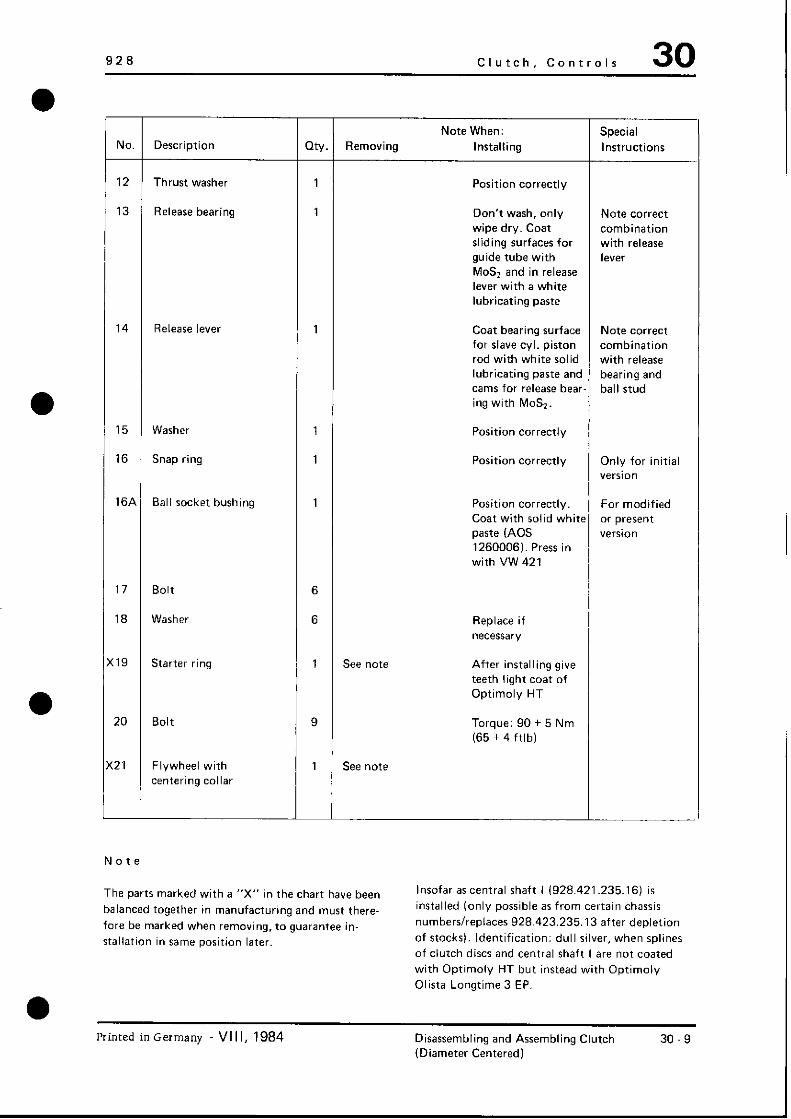
12 Thrust washer 1 Position correctly
13 Release bearing 1 Don’t wash, only Note correct wipe dry. Coat combination sliding surfaces for with release guide tube with level MO& and in release lever with a white lubricating paste
14 Release lever 1 Coat bearing surface Nate correct for slave cyl. piston combination rod with white solid with release lubricating paste and bearing and cams for release bear- ball stud ing with MO&.
15 Washer 1 Position correctly
16 Snap ring 1 Position correctly Only for initial version
16A Ball socket bushing 1 Position correctly. For modified Coat with solid white or present paste (AOS version 1260006). Press in with VW 421
17 Bolt 6
18 Washer 6 Replace if necessary
19 Starter ring 1 See note After installing give teeth light coat of Optimoly HT
20 Bolt 9 Torque: 90 + 5 Nm (65 + 4 ftlb)
:21 Flywheel with 1 See note centering collar
Note
The parts marked with a “X” in the chart have been balanced together in manufacturing and must there- fore be marked when removing, to guarantee in- stallation in same position later.
Insofar as central shaft I (928.421.235.16) is installed (only possible as from certain chassis numbers/replaces 928.423.235.13 after depletion of stocks). Identification: dull silver, when splines of clutch discs and central shaft I are not coated with Optimoly HT but instead with Optimolv Olista Longtime 3 EP.
Printed in Germany VI I I, 1984 Disassembling and Assembling Clutch (Diameter Centered)
30 9

30 Clutch/Conrrols
30 - 10 Disassembling and Assembling Printed in Germany Clutch (Dowel Pin-Centered)

928 Clutch/Controls 30
1
IX
)
No. Description cay. Note When: Special Removing Installing Instructions
1 Bolt 2 Tighten to specified torque
2 Washer 2 Replace if necessary
3 Guide tube 1 Coat sliding See page surface for release 30 13 bearing with MoS,
4 Central shaft I 1 Lubricate splines See page with grease 30.13and depending on 30 - 16a version
5 Bolt 6 Loosen one Screw in after the other uniformly and and by 1 to tighten to spe- 1 l/2 turns cified torque.
Then remove clip
6 Washer 6 Replace if necessary
,7 ; Pressure plate with 1 See note Check for wear. , three centering bores Give preload
washer light coat of Optimoly HT in area of no. 12 and no. 15
8 Clutch disc I I 1 (spring-loaded)
Inspect. Lubricate See page splines acccentral 30 13 and shaft I. Watch 30.16a position to no. 10
(9 Intermediate ring 1 See note Prior to installa- See page with riveted starter tion push three 30-13 ring adjusting elements
toward release bearing. Thin coat of Optimoly HT on spline of starter ring after installation
0 Clutch disc I 1 Inspect. Lubricate See page (spring-loaded) splines acccentral 30 13 and
shaft I. Watch 30-16a position to no. 8
Printed in Germany VI I I, 1984 Disassembling and Assembling Clutch 30-11 (Dowel Pin Centered)

30 Clutch, COntrOlS 928
Note When: Special
NO. Description Qty. Removing Installing Instructions
11 Snap ring 1 Important! Install snap ring EO that gap is between retainer (turning lock) on release bearing or on new release bearings offset to groove in release bearing
12 Thrust washer 1 Position correctly
13 Release bearing 1 Don’t wash, only wipe dry. Coat sliding surfaces for guide tube with MO& and sliding surface in release lever with solid white paste
14 Release lever 1 Coat bearing surface Coat contact for slave cylinder areas for piston rod with release bearing solid white paste with MO&
15 Washer 1 Position correctly
16 Ball socket bushing 1 Position correctly. Coat with solid white paste (AOS 1260006l. Press in with VW 421
17 Centering pin 3 Straighten or replace damaged pins. Protrusion beyond bearing surface of intermediate ring on flywheel 3.5 - 0.5 mm. Must have tight fit
18 Bolt 9 Torque: 90 + 5 Nm (65 + 4 ftlb)
:19 Flywheel with 1 centering bores
Note
Parts in table marked with “X” were balanced together in manufacturing and must therefore be marked prior to removing for installation in same position later (also refer to procedures).
30-12 Disassembling and Assembling Clutch (Dowel Pin Centered)
Printed in Germany

928 Clutch/Controls 30
CHANGES ON CLUTCH/ INSTRUCTIONS FOR REPLACEMENTS
Clutch discs with symmetric liner springs and a longer hub were introduced as from December, 1980 in standard production to improve engaging behavior. In conjunction with this changes were also necessary on the clutch intermediate ring, central shaft I and release bearing tube. From 1984 models on cars have a separate test connection to check the ignition timing. This changed the dowel pin centering of the clutch in such a manner that the intermediate ring can now only be installed in correct position to the flywheel.
Survey of Changed Parts
Description Up to Dec., 1980
Clutch disc I (front) 928.116.011.23
Clutch disc II (rear) 928.116.011.24
Intermediate ring 928.116.033.17
Central shaft 928.421.235.12
Release bearing tube 928.116.087.11 928.116.087.13
Changed/Presently
928.1 16.011.27 or 928.116.011.33
928.116.011.28 or 928.116.011.34
928.116.033.22 since 1984 mod. 928.116.033.26
928.421.235.13 or 928.421.235.16
Printed inGermany VIII, 1984 Disassembling and Assembling Clutch 30-13 (Dowel Pin Centered)
30 Clutch, Controls 928
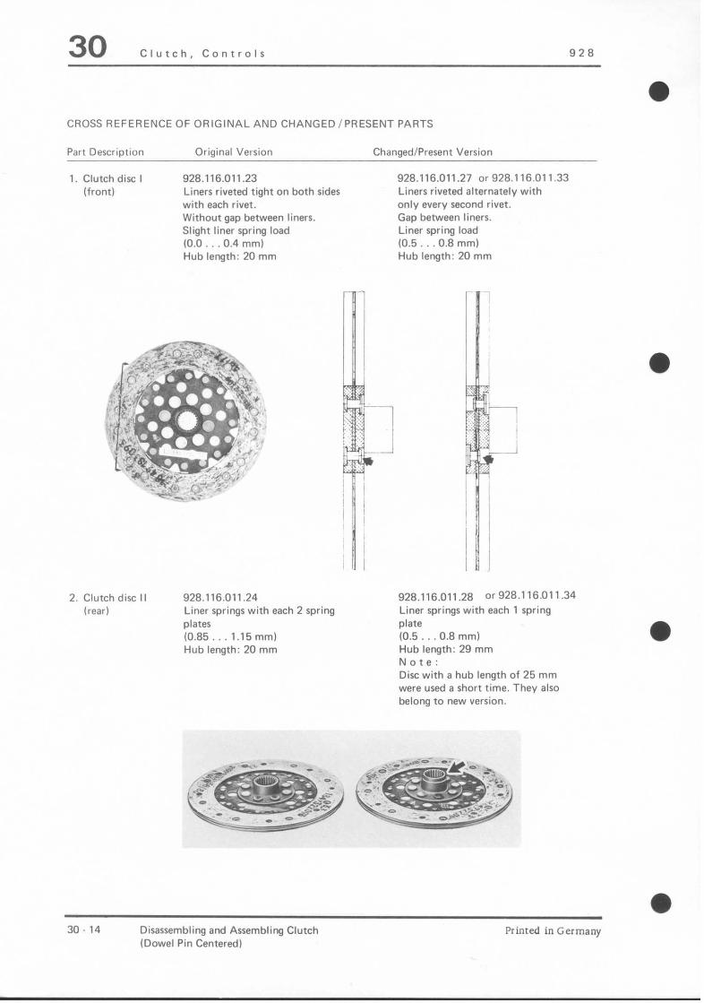
a CROSS REFERENCE OF ORIGINAL AND CHANGED/PRESENT PARTS
Part Description Original Version Changed/Present Version
1. Clutch disc I (front)
928.116.011.23 Liners riveted tight on both sides with each rivet. Without gap between liners. Slight liner spring load IO.0 0.4 mm) Hub length: 20 mm
2. Clutch disc II (I-Z?tW)
928.116.011.24 Liner springs with each 2 spring plates (0.85 1.15 mm) Hub length: 20 mm
928.116.011.27 or 928.116.011.33 Liners riveted alternately with only every second rivet. Gap between liners. Liner spring load (0.5 0.8 mml Hub length: 20 mm
928.116.011.28 or928.116.011.34 Liner springs with each 1 spring plate (0.5 0.8 mm) Hub length: 29 mm Note: Disc with a hub length of 25 mm were used a short time. They also belong to new version.
30-14 Disassembling and Assembling Clutch (Dowel Pin Centered1
Printed in Germany

928 Clutch, Controls 30
a
+%tDew*m ori@mi ver+n Changedii%sem Version
3. Intermediate ring 928.116.033.17 928.1 16.033.22 Travel: 0.7 1.0 mm Travel: 1.2 1.5 mm Label 3059 008 001 Label 3059 008 101
since ‘84 models 928.116.033.26
Note: (modified dowel pin centering, page 30 16 a)
If the label is missing, the travel could be determined as follows.
Press down clutch ring from starter ring side against stop. Determine gap distance on guide with a feeler gauge blade
New version - at least 1.2 mm Old version - at least 1 .O mm
4. Short drive shaft 928.421.235.12 Tooth distance “A” 51 mm
5. Guide tube 928.116.087.11 928.116.087.13 Total length distance “X” Total length distance “X” 50 mm 49 mm
928.421.235.13 (grayiblackl or 928.421.235.16 (dull silver) Spline distance “A” 56 mm
Primed in Germany VIII, 1984 Disassembling and Assembling Clutch 30.15 (Dowel Pin Centered)

30 Clutch/Controls 928
Replacement Procedures:
Intermediate ring, central shaft and release bearing tube are no longer available in the original version.
Clutch discs I and II are still available in original version for the diameter and dowel pin centered clutch.
Parts of the modified/present and original version may not be installed together in one car. See remarks for exceptions. Check chart below when repairing clutches with modified/present clutch parts (dowel pin centered clutch).
Part Description Part Number Version
Clutch disc I
Intermediate ring
928.116.011.27 or 928.116.011.33
928.116.033.22 or 928.116.033.26
Clutch disc I I 928.116.011.28 or 928.116.011.34
Central shaft I (928.421.235.12) 928.421.235.13 or 928.421.235.16
Release bearing tube 928.116.087.13 or 928.116.087.11 modified
Modified (see remarks) Present
Modified Since 1984 models (see remarks)
Modified (see remarks) Present
Original version Modified version Present version (see remarks)
Modified/present
Original version (see remarks)
Remarks:
Clutch Discs I and Ii Modified clutch discs I, 928.116.011.27. and II, 928.116.011.28, were replaced with clutch discs, 928.116.011.33 and 928.116.011.34 (different liner grade). Identification: color of liners. Clutch discs 928.116.011.27 and 928.116.011.28 will not be available after depletion of stocks. Clutch discs with different type liners should not be installed together in one car.
a 30-16 Disassembling and Assembling Clutch Printed in Germany
(Dowel Pin Centered)

-
a
928 Clutch/Controls 30
Intermediate Ring
Beginning with 1984 models there is a separate test connection, which is connected with a TDC sensor, for checking the ignition timing. The TDC sensor signal is triggered by two cylindrical pins which are pressed in the gear ring of the clutch intermediate ring. This makes precise positioning between the intermediate ring and flywheel necessary. This position is guaranteed, in that one of the three centering pins in the intermediate ring has two different diameters on each end, namely 6 mm and 8 mm. A centering bore in the flywheel now has a 8 mm diameter. Consequently the intermediate ring can only be mounted in one position.
Central Shaft I
The first version of central shaft 928.421.235.12 (no longer available) was sometimes installed together with new clutch parts. The modified central shaft 928.421.235.13 was replaced with central shaft 928.421.235.16 (hard nicle-plated/same size) as from June of 1983. Central shaft 928.421.235.13 will no longer be available after depletion of stocks. Axial movement of clutch discs on central shaft I is better after long operating time when using the hard nickle-plated version in conjunction with the specified lubricant.
Identification: 928.421.235.13 gray/black 928.421.235.16 dull silver
Lubricant specifications for splines (central shaft I and clutch discs):
928.423.235.12 and 928.423.235.13 very thin coat of Optimoly HT
928.423.235.16 coat of Optimoly Olista Longtime 3 EP (Part No. 000.043.024.00)
Release Bearing Sleeve
When repairing clutch, the old release bearing sleeve 928.116.087.11 with a total length of 50 mm can be ground off to a length of 49 mm.
Printed in Germany - VIII, 1984 Disassembling and Assembling Clutch 30.16a (Dowel Pin Centered)

928 Clutch, Controls 30
DISASSEMBLING AND ASSEMBLING CLUTCH
Differences in tolerances could make it necessary to
preload the clutch to be able to install the release
bearing and release lever.
Disassembling
3. Place pressure plate and release lever on a work-
bench. Press down on thrust washer and remove
snap ring of release bearing. Bent section of
release lever should project over workbench so
that pressure plate and thrust washer can move
downward and make the snap ring accessible.
1. Pry the pressure plate off of the intermediate plate
uniformly (if a dowel pin-centered clutch).
2. Place pressure plate in a press so that, when pre-
loading. the release lever can be moved out down-
ward without interference. Preload pressure plate
carefully until 4 mm thick locally made wire tool
can be slid underneath heads of mounting bolts.
1 r -9 E
,‘-1,
c t
ca.32 “l”,
Assembling
1. Install diameter-centered or dowel pin-centered
pressure plates and intermediate plates only
with the matching flywheel.
See page 30 7 for flywheel of diameter.
centered clutch.
See page 30 - 10 for flywheel of dowel pin-
centered clutch.
2. Inspect parts of clutch and. if necessary. replace
(also refer to page 30.23124). Also slide 4 mm
thick locally made wire tool underneath bolt
heads of new version pressure plate. Place this
pressure plate on a level plate in a press for
preloading. Bearing surface on pressure plate
must not scrape on pressure plate housing while
pressing together.
Printed in Germany VI, 1982 Disassembling and Assembling Clutch 30.17 (Diameter and Dowel Pin Centered)

30 Clutch, Controls 928
Note
Don’t forget to remove wire clip after installation of
clutch.
_~~ -@T -
- P
5. Check position of centering pins of a dowel pin.
centered clutch. correcting if necessary.
Protrusion of pins over bearing surface of inter-
mediate plate on flywheel: 3.5 - 0.5 mm
(distance A).’
-*.-A b? . . ‘7&-.-*y- 2 ” 8: 1
3. Inspect ball socket bushing (snap ring) in release
lever. If necessary, install a new ball socket bushing
and press in against stop with Special Tool VW 421
Vent hole in release lever must not be covered,
otherwise ball socket bushing would spring back
when air can’t escape.
4. Lubricate bearing surface of release bearing in
release lever as well as both sides of preload washer
for pressure plate in area of release bearing with
Optimolv HT. Mount release bearing with washer
and release lever on pressure plate. Gap of circlip
should be between retainer on release bearing or
offset to groove in release bearing when bearing has
an opening.
* Only applicable for the two 6 mm diameter
centering pins of cars beginning with 1984
models, since the stepped 6/B mm diameter pin
is removed for installation and removal.
Distance A could also not be reached.
6. Push intermediate plate in direction of .elease
bearing on the three adjusting elements.
7. Assemble clutch, observing the following points:
a) Yellow arrows on discs are mounted 180”
opposite (residual unbalance).
bl White mark on disc (without spring-loaded
liner) faces flywheel.
cl Hubs of discs face release bearing.
a 30.18 Disassembling and Assembling Clutch
(Diameter and Dowel Pin Centered) VIII, 1984 -Printed in Germany

928 Clutch, Controls 30
d) Transfer residual unbalance mark of discs
(yellow arrows) to engine side of same
(facilitates assembly work).
4 Mark pressure plate before installing; drive
pressure plate of dowel pin centered clutch on
to centering pins or into intermediate plate
witi, a plastic hammer far enough, so that the
drive plate located between both can still be
moved with short drive shaft (central shaft I).
fl Pressure plate and intermediate plate are also
marked with dots of white paint (residual
unbalance/heavy side), which are mounted
offset 180’ (opposite). This must be con-
sidered when replacing one or both parts.
g) Recheck protrusion of centering pins on fly-
wheel (3.5 - 0.5 mm), correcting if necessary.
h) Lubricate parts to specifications (see table);
however lubricate the starter ring after
installation of the clutch. Don’t forget to
lubricate guide tube for the release bearing.
-
a Printed in Germany - VI, 1982 Disassembling and Assembling Clutch 30.19
(Diameter and Dowel Pin Centered)
30 Clutch, Controls 928
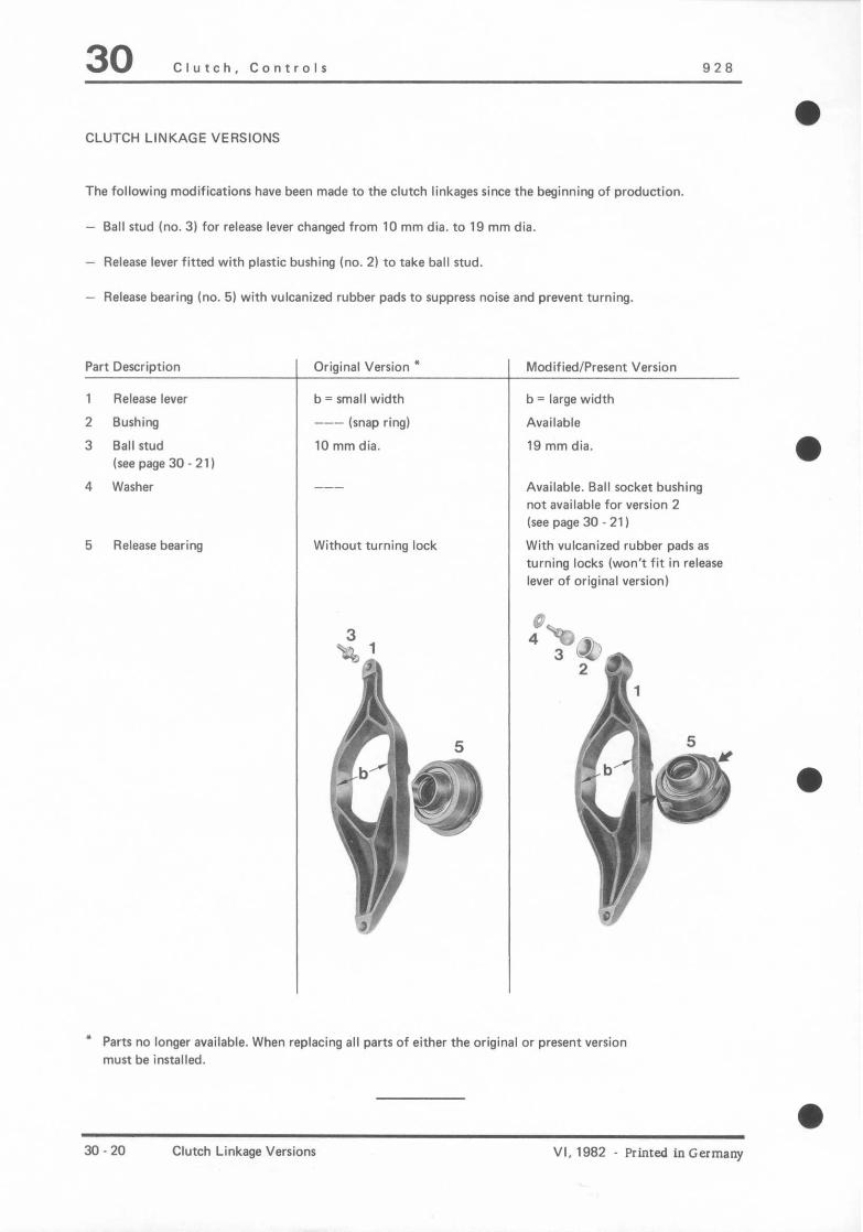
a CLUTCH LINKAGE VERSIONS
The following modifications have been made to the clutch linkages since the beginning of production.
- Ball stud (no. 3) for release lever changed from 10 mm dia. to 19 mm dia.
- Release lever fitted with plastic bushing (no. 2) to take ball stud.
- Release bearing (no. 5) with vulcanized rubber pads to suppress noise and prevent turning.
Part Description
1 Release lever
2 Bushing
3 Ball stud
(see page 30 - 21)
4 Washer
5 Release bearing
Original Version *
b = small width
--- (snap ring)
10 mm dia.
Without turning lock
b = large width
Available
19 mm dia.
Available. Ball socket bushing
not available for version 2
(see page 30 - 21)
With vulcanized rubber pads as
turning locks (won’t fit in release
lever of original version)
l Parts no longer available. When replacing all parts of either the original or present version
must be installed.
30.20 Clutch Linkage Versions VI, 1982 - Printed in Germany

928 Clutch, Controlr 30
BALL STUD VERSIONS
1 - Original version with 10 mm ball diameter. M 6 threads (originally this version was without threads. also refer to “Replacing Ball Stud”).
2 - Modified version, 19 mm ball diameter, M 6 threads without washer (was used briefly in standard production).
3 - Modified version, 19 mm ball diameter,
l M 6 threads with washer.
4 - Present version, 19 mm ball diameter, M 8 threads with washer.
REPLACING BALL STUD
1. Unscrew ball stud after removing clutch (air cleaner removed).
Note
Ball studs are locked with Loctite so that removal must be done carefully and perhaps turning back and forth several times will be necessary. Heat a removed clutch housing (up to about 250 “C/480 OF) to facilitate removal of the ball stud.
2. Clean threads with, for example, Loctite Cleaner 0706 prior to screwing in a new ball stud (19 mm dia. instead of 10 mm dia.). Spread a thin coat of Loctite 270 on thread flanks. Screw ball stud version 3 with washer in clutch housing. After depletion of stocks version 3 will no longer be available. Then use ball stud version 4 with washer (tap M 8 threads in clutch housing).
The ball stud in cars prior to Chassis Number
9288200491
is not screwed, but pressed in. On these cars the replacement of the ball stud will require installing a M 6 - hnw, p ” H-lwm
For ball stud version 4 (after depletion of version 3 stocks) the clutch housing has 8 mm threads (without a threaded insert).
Printed in Germany - VI, 1982 Ball Stud Versions Replacing Ball Stud
30.21

30 Clutch, Controls 928
These jobs can only be performed after removal of REMOVING AND INSTALLING CLUTCH
the clutch housing. HOUSING
Removing
1. Remove front exhaust lines.
2. With clutch removed unscrew mounting bolts
for central tube to clutch housing and clutch
housing to engine.
3. Remove both mounting bolts of transmission
mounts on rear axle cross member.
Tl * 7
4. Apply tire iron con transmission and rear axle
cross member. Push back transmission and
central tube far enough so that the clutch
housing can be removed.
30.22 Replacing Ball Stud
Removing and Installing Clutch Housing
Printed in Germany

928 Clutch, Controls 30 l
Installing CHECKING CLUTCH DISCS
Installation in reverse order.
Watch specified torque.
1. Inspect splines. Clutch discs must slide easily on
short drive shaft. Slight radial play is designed
in and is not important.
2. Inspect rivets. Replace clutch disc when in
doubt.
3. Inspect clutch linings. If clutch linings are
covered with oil, burnt, damaged or worn
locally, install a new clutch discs.
4. Check lining thickness of clutch discs. Measure
distance from lining to highest point (rivet) on
all four linings. Replace clutch discs when less
than 0.3 mm.
Note:
See page 30. 14 for former version clutch discs.
Since clutch discs will be subject to different
degrees of wear in operation. the lining thickness
will vary. On unsprung disc the flywheel end lining
between the flywheel and intermediate plate (white
dot of paint) will be considerably thinner.
5. Check clutch discs with lining for lateral runout.
Max. permissible lateral runout at 190 mm dia.:
0.4 mm.
l Printed in Germany - VI, 1982 Removing and Installing Clutch Housing
Checking Clutch Discs 30.23

30 Clutch, Controls 928
CHECKING CLUTCH PRESSURE PLATE
Clutch pressure plates have not been designed to
permit overhauling or repairing. Checking is limited to
dry cleaning and removing of dust with compressed
air and emery cloth as well as a thorough visual
inspection.
1. Clean clutch. Clean bearing surface of pressure
plate with emery cloth, if necessary. Then blow
out entire mechanism thoroughly with compressed
air.
2. Check tips of diaphragm springs for traces of wear
from clutch release bearing. Scoring to a depth of
0.3 mm is not significant.
3. Inspect bearing surface of pressure plate for
cracks, burnt spots and wear. Check deflection
with a steel ruler. Pressure plates with up to
0.3 mm deflection inward (measured with a feeler
gauge blade1 can still be used.
4. Inspect spring connections between pressure plate
and cover for cracks. Check tightness of rivets.
Replace pressure plates with damaged or loose
rivets.
CHECKING CLUTCH INTERMEDIATE PLATE
Clutch intermediate plates have not been designed
to permit overhauling or repairing. Checking is
limited to dry cleaning and removing of dust with
compressed air and emery cloth as well as a
thorough visual inspection.
1. Clean intermediate plate. Clean bearing surfaces
with emery cloth when necessary. Polish out
burnt spots. Blow out entire mechanism with
compressed air.
2. Check bearing surfaces for cracks, burnt spots
and wear. Check deflection with a steel ruler.
Intermediate plates with up to 0.3 mm
deflection inward (measured with a feeler
gauge blade) can still be used.
3. Inspect spring connection between intermediate
plate and intermediate plate housing for cracks.
Inspect rivets for tight fit and adjusting elements
for damage, replacing intermediate plate if
necessary.
4. Check tight fit of centering pins in intermediate
plate of dowel pin centered clutch. Straighten
or replace bent or damaged centering pins.
30-24 Checking Clutch Pressure Plate Printed in Germany Checking Clutch Intermediate Plate

928 Clutch, Controls 30 a
OVERHAULING CLUTCH SLAVE CYLINDER
a
Printed in Germany - VI, 1982 Overhauling Clutch Slave Cylinder 30-25

30 Clutch, Controls 928
NO. -
1
2
3
4
5
6
7
8
9
10
-
Description
Circlip
Push rod
Rubber cover
Retaining ring
Piston
Dust cover
Spring
Dust cap
Bleeder screw
Clutch slave cylinder
-
Qty
1
1
1
1
1
1
1
1
1
1
-
Removing
Note When:
Installing
Replace, concave
side faces in, make
sure of proper fit
Replace, coat very
slightly with brake
cylinder paste
Position correctly
Special
Instructions
Clean thoroughly
with gasoline. Apply
a very thin coat of
brake cylinder paste
to cylinder bore
30-26 Overhauling Clutch Slave Cylinder Printed in Germany

928 Clutch, Operation 30
Checking clutch disc for wear
Clutch disc is removed
Checking:
Using a depth gauge, check thickness of lining to rivet head (dimension X).
Note
Measure only on flared riied head side.
1 - Lining 2 - Clutch disc/lining spring
Dimension X is approx. 1.4 mm for new
clutch discs. If dimension X is down to 0.3 mm, the clutch
disc is worn and must be replaced. Please note that lining wear is not linear over the entire lie of the clutch. Wear decreases considerably as the clutch
mileage increases.
a Checking clutch disc for wear 30 - 27
Primed I” osrmsny - XXIX, 1992

928 Torque Converter 32
e TOOLS
Ilo. Description Special Tool Remarks
1 Transmission holder ‘9162
2 Deprh gauge __. Sandaid roul
3 Grip plare 9301
‘I Mandrel !I310
e Printed in Germany - 111, 1”‘!1 Removing and Installing Converter 37. - 1
32 Torque Converter 928
K P
PI
-_i NY P
-,T a;
m :,+iglz.m -lL;L -“I
,, > a3 -
co
32 - 2 Removing and Installing Converter Printed in Germany

l
928 Torque converter 32
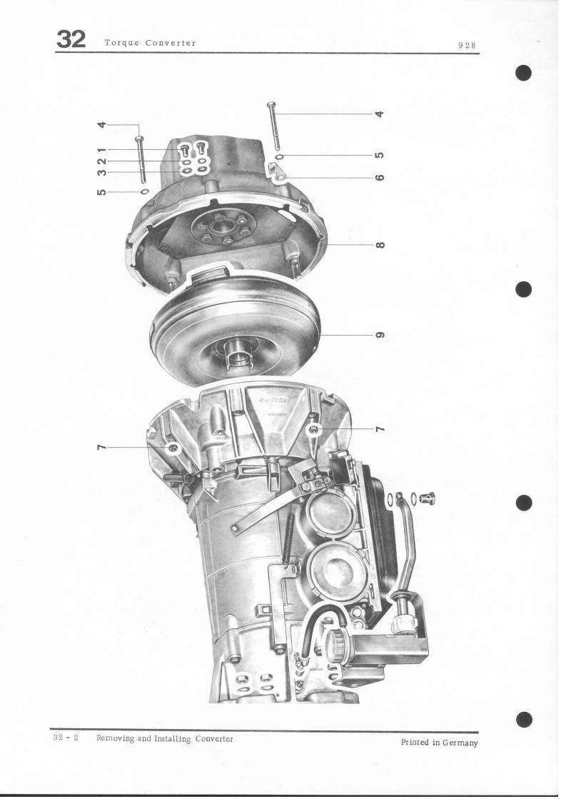
No. Description
1 BOlC
Qty. Note When Special
Removing Installing insrrucrions
6 Tighten 1” specified torque
2 Washer 6
3 Washer 6
4 Bolt a Tighten to specified rorque
5 Washer a
6 Vacuum line holder 1
7 Nut 8
8 Front converter housing 1
3 Torque converter 1 Remove upward Replace when wear
carefully with is excessive “I ATF Special Tool 9301 has meral parricks.
Lubricate input flange and shaft/bearing journals wirh a mulri- purpose grease con- taining M”SZ. Place rransmission uprlght and run in carefully with Special Tool 9301.
l Printed inGermany _ 11, 1979 Removing and Installing Torque Convener 32 - 3
32 Torque Converter
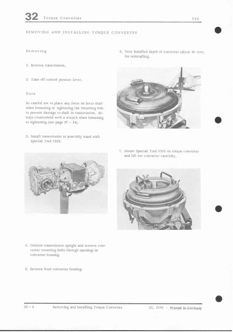
REMOVING AND INSTALLING TORQUE CONVERTEQ
Removing
1. Remove rransmission.
2. Take off conrrol pressure lever.
Note
Be careful not IO place any force on lever shafr when loosening or tighrening the mounring bolt. to prevent damage to shafr in transmission. Al- ways counterhold with a wrench when loosening or tightening (see page 31 - 14).
6. Note installed depth of conwrier iabout 4’1 mm) for reinstalling.
II
a,’
i-.*Jyi--
rs- .. _ \
-.:’
~,K- *
* y:-,: $g&l l 3. Install lransmission in assembly stand wirh
Special Tool 0162.
I. Mounr Special Tool 9301 on torque convener and lifr OUI converter carefully.
4. Position transmission upright and remove con- vertex mounring bolts through openings in converter housing.
5. Remove front converter housing,
32 - 4 Removing and installing Toro.ue Converter
0 111. 11180 - Printed inGermany

‘128 Torque Converler 32 Installing
%b r 4, 7 ‘L _
&. c 7;. .
PJore *
If ATF contains clutch plare/brake band facing particles, clean inside of torque converwx with Special Tool 9310 (flushing mandrel). Fill con- vertex with about 1 lirer/quarr of kerosene. insrall flushing mandrel and turn same with a drill running at slow speed. Repeal these procedures twice and ler the fluid drain through rhe drain
Plug.
If there are metal panicles in oil rump of trans mission. rorque converter will have 1” be re- placed.
4. Run in conveyer carefully. turning it back and forth slighrly. Also be careful nor I” damage seal while running in converter.
1. Mount Special Tool 9301 on converter.
2. Lubricate input flange and bearing journal of converter with a multi-purpose grease con- raining MoS2 additives.
5. Measure installed depth (about 49 mm) of con- vener. I” make sure that converrer is positioned correctly. Install from converter housing.
3. Place transmission upright. Position drive dog on convener input flange opposite impeller for engagement.
Primed inGermany - ill, 1930 Removing and Insralling Torque Converrer 32 - 5

928 Manual Transmission/Controls, Case 34 CHANGING TRANSMISSION OIL
Filling capacity approx. 3.8 liters/E US pints of hypoid oil SAE 90, MIL-L-2105 B; API Classifi- cation GL 5
2. Clean filler plug. drain plug for manual trans- mission and also magnetic drain plug for differential, and tighten them to torque of 1.9 to 2.3 mkg (14 to 17 ft lb).
I. Drain oil when transmission has reached operating temperature. Oil has to be drained from transmission and differential separately.
3. Add transmission oil with car on level surface until oil flows out of filler plug opening cap- prox. 3.8 l/8 US pints).
1 Drain plug
” hlagnvtic drain plug
I: rillcr plug
Primed in Germany C hanging Trianilnission Oil R‘l 1

92E Manual Transmission/Controls. Cake 34
TOOLS
.).‘, i , p
2
_ -
3s 3
: i
,’ i
Description
Transmission support US 618
Support bracket US 618/Z
Support bracket US 618/4
Special Tool Remarks
Printed inGermany - Iv. 1980 Removing and Installing Trammission 34 - 3
928 Manual Transmission/Controls. Case 34 REMOVING AND INSTALLING TRANSMISSION
Removing 5. Remove battery (only for cars with bolted bat- tery console).
1. Disconnect ground strap at battery.
2. Loosen rear wheels. Engage 5rh gear.
6. Turn one rear wheel (holding wheel on opposite side) to position coupling bolt between input shaft and drive shaft, and remove bolt.
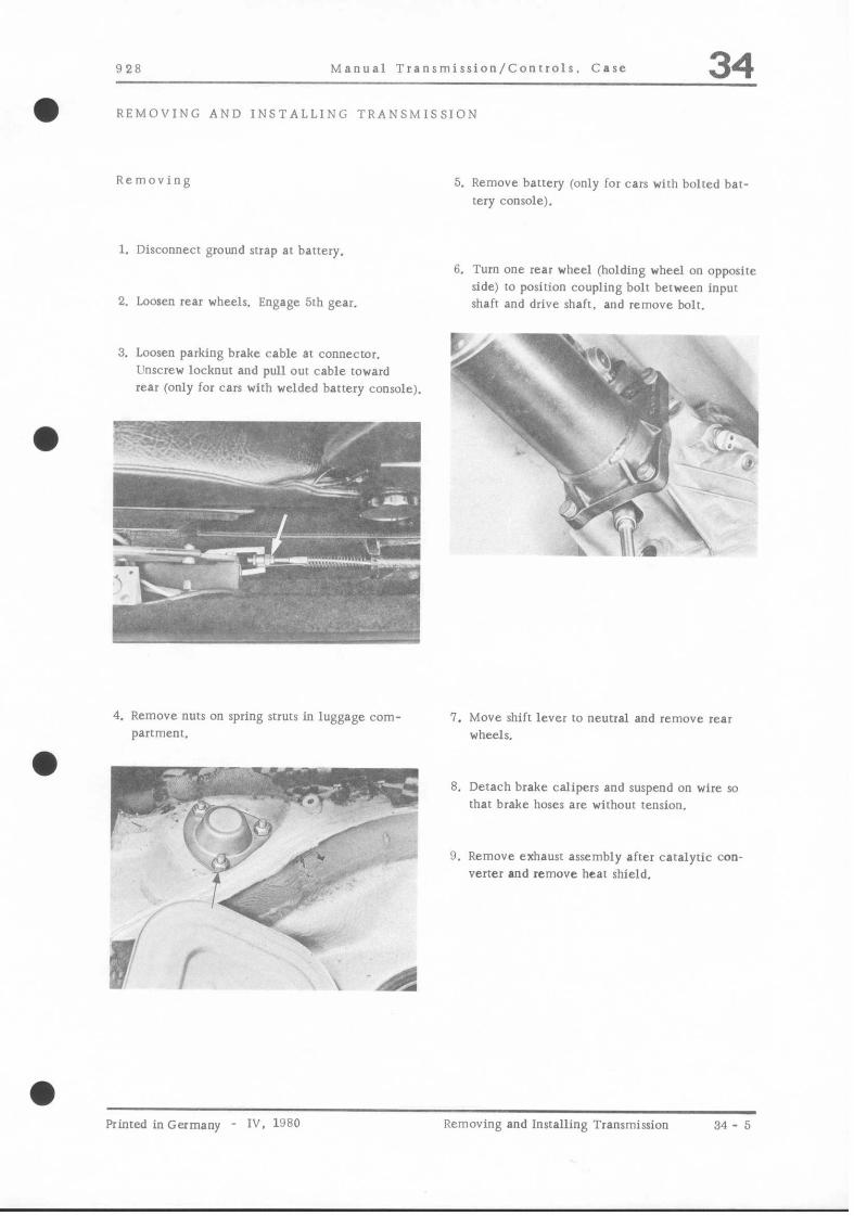
3. Loosen parking brake cable at connecror. Unscrew locknut and pull out cable toward rear (only for cars with welded battery console).
1
.-
r
4. Remove nuts on spring struts in luggage com- parrment.
7. Move shift lever IO neutral and remove rear wheels.
8. Detach brake calipers and suspend on wire so that brake hoses are without tension.
9, Remove exhaust assembly after catalytic con- verter and remove hear shield.
Printed inGermany - IV. 1980 Removing and lnsralling Transmission 34- 5
34 Manual Transmission/Controls. Case 928
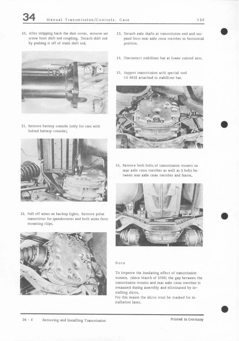
10. After stripping back the dust cover. remove set scw# from shift rod coupling. Detach shift rod by pushing it off of main shift rod.
11. Remove battery console (only for cars with bolted battery console).
12. Pull off wires on backup lights. Remove pulse transmitter for speedometer and both wires from mounting clips,
.: $
13. Detach axle shafts ar transmission end and sus- pend from rear axle cross member in horizontal position.
14. Disconnecr srabilizer bar at lower control arm.
15. Support transmission with special tool US 8031 attached to stabilizer bar.
mv!B!!we ,,~&-L?~‘~ ‘T- , d J;.‘; ‘._ ,
16. Remove both bolts of transmission mounts on rear axle cross member as well as 2 bolts be- tween rear axle cross member and frame.
To improve the insulating effect of transmission mounts, (since March of 1980) rhe gap between the transmission mounts and rear axle cross member is measured during assembly and eliminated by in- stalling shims. For this reason the shims must be marked for in- stallation later.
34 6 Removing and Installing Transmission Printed in Germany

!I 28 Manual Transmisrion/Conrrolr. Case 34 17. Place floor crane underneath rear axle cross
member. Mark poririon of rear axle cross member. Remove last 4 bolts on rear axle cross member. Tilt real axle carefully. making sure that spring strms or conrrol a,ms do nor twist. Support rear axle in tilted posirion m keep rhe entire weight off of the lower control arm link pins.
Note
Entire rear axle assembly of cars with a welded battery console must be removed. Mark roe eccen- tric for installation later and remove eccentric bolts.
18. Mount transmission supporl/bracker on wanr mission. Remove 6 bolts between central tube and transmission. as well as Special Tool US 802!!. Pull back rransmission IO one side and lower.
Installing
1. Install the marked spacers or spacers of derer- mined thickness between the transmission mounts and rear axle cross member (see page 34 8 a).
2. Watch marks of toe eccentric and cross member IO body when insralling rhe rear axle.
3. Adjust parking brake (see page 46 8).
4. Observe the specified torque values.
Printed inGermany IV. 1980 Removing and Installing Transmission 34 - 7

928 Manual Transmission/Controls. Care 34 ADJUSTING TRANSMISSION SUSPENSION
a
To prevent stress in transmission suspension and to provide good insulation. transmission mounts have to be adjusted.
1. Install transmission and rear axle. Tighten trans- mission mount to transmission case bolts to spe- cified torque.
2. Screw in cross member to transmission mount bolts several turm.
3. Lift transmission at center of case enough so that there is a gap between both transmission mounts and the cross member. Measure this gap
on both sides and take up difference with shims.
9
.., 8I.Y.
I& nq;,,; I,,,, .; -;,
1
,. - ~., , I,’ - /
,..:I., ./I .f s+>,.. ‘^’ “%z,+$JL ; .;#-\ ,+-
. .*z& (~., +;$t,,
* ;:;:..:
r :qy “,.
“a,-
‘.: ‘a
;.. 1, ” : ‘. ,;<, “,,,Q 4 Lo-
4. Place shims of determined thickness between the transmission mount and cross member, low- er transmission and tighten transmission mount to cross member bolts to specified torque.
Note
There must he at least 1 mm clearance between transmission case and side stop an transmission mount after tightening the mounting bolts.
a
Printed in Germany - IV. 1980 Adjusting Transmission Suspension 34-8a

928 Manual Transmission/Controls, Care 34
a
Printed in Germany - Iv. 1980 Disassembling and Assembling Shift Linkage 34 - 8 c
34 Manual Transmission/Controls, Case 928
I
Note When: Special
NO. Description Qty. Removing Installing Instructions
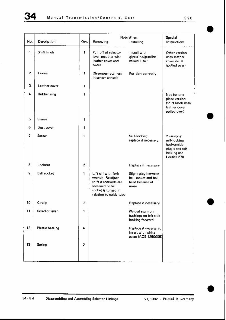
1 Shift knob 1 Pull off of selector Install with Other version
lever together with glycerine/gasoline with leather leather cover and mixed 1 to 1 Cwer no. 3 frame (pulled over)
2 Frame 1 Disengage retainers Position correctly in center console
3 Leather cover 1
4 Rubber ring 1 Not for one piece version
(shift knob with leather cover pulled over)
5 Sleeve 1
6 Dust cover 1
7 SW&V 1 Self-locking, 2 versions:
replace if necessary self-locking (polyamide plug); not self- locking use Loctite 270
a Locknut 2 Replace if necessary
9 Ball socket 1 Lift off with fork Slight play between wrench. Readjust ball socket and ball shift if locknuts are head because of loosened or ball noise
socket is turned in relation to guide tube
10 Circlip 2 Replace if necessary
11 Selector lever 1 Welded seam on
bushings on left side looking forward
12 Plastic bearing 4 Replace if necessary. Insert with white paste (AOS 1260006)
13 Spring 2
34.8d Disassembling and Assembling Selector Linkage VI, 1962 Printed inGermany

928 Manual Transmission/Controls. Case
Note When
NO. Description my. Special Instruc
Removing Installing tions
14 Friction plate 1 Lubricate with while paste (AOS 1260006)
15 Guide rod 1 In neutral shift lever must be inclined toward rear by 2.5 i 2’. Adjust by turning ball socket. Lubricate all bushings with white paste (AOS 1260006)
16 Shift rod 1
17 Nut 1 First adjust shift lever lateral angle and then tighten nut to specified torque.
18 Lockwasher 1 Replace, if necessary
19 Bolt 1
20 Shift rod coupling 1 Push in shift rod flush. Adjust shift lever cross angle.
21 Nut 1 Align ball socket and shift lever prior to tightening
22 Guide rod bracket 1 Mounted to hoc a 0” central tube
23 Insulation 1 Held on central tube with tape. Use tire
paste, e.g. Contifix. to facilitate.
14 Washer 2 Replace. if necessary
Printed in Germany - IV, 1980 Disassembling and Assembling Shift Linkage 34 - 8 e

34 Manual Transmission/Controls, Case 928
DISASSEMBLING AND ASSEMBLING SELECTOR LINKAGE
Disassembling
Pry ball socket off of ball head. Disconnect bracket,
in so far as it is mounted on the frame tunnel, to
remove the central tube (see “Removing and
Installing Central Tube”).
2. Mount bearing unit (selector rod coupling) on
interior selector rod of transmission with
tapered bolt. If applicable, use Loctite No. 270
(see page 34 .8 dl.
3. Assemble guide tube with bracket (guide tube
bearing) and ball socket. Assemble selector
lever, selector rod and guide tube, lubricating
all bearing surfaces with white paste
(AOS 1260006). Don’t tighten locknut for
ball socket or selector rod to bearing unit
(selector rod coupling) mounting bolt at this
point.
Assembling
1. Place transmission on a workbench and apply a
piece of wood underneath rear end so that
transmission is approximately horizontal. Bolt on
central tube with 2 bolts and support from
underneath with an universal transmission lift.
34.8f Disassembling and Assembling Selector Linkage VI, 1982 - Printed in Germany

928 Manual TransmirsionlControls, Case 34
4. Adjust shift to guarantee correct shift travel.
Keep to the order of selector lever axial and then
lateral inclination.
The adjustment differs according to the mounting
of the bracket. It is bolted on the central tube or
body.
cl Adjust selector lever lateral inclination. With
transmission in neutral position turn bearing
unit anticlockwise against stop and hold.
Turn selector rod with selector lever until the
selector lever is inclined to the left by 2 to 3”.
Clamp selector rod flush with the bearing unit
in this position (arrow = forward direction).
Bracket Mounted on Central Tube
(Present Version1
a a) Place insulation sheet on central tube and mount
bracket (guide tube mount) on the central tube.
a b) With transmission in neutral position push selector
rod on to bearing unit (selector rod coupling)
against the stop.
,‘T. \
---$--J&v&‘r’ @s i’ + +&, -: _I.
[ x-.; ;-. -jr;
Printed in Germany VI, 1982 Disassembling and Assembling Selector Linkage 34.89
34 Manual Transmission/Controls. Case 928
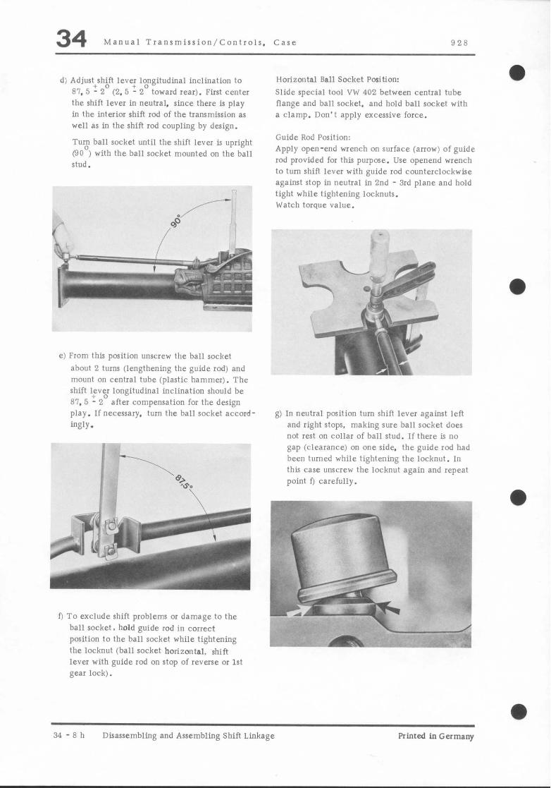
d) Adjust+sh;ft leve: 1;ngitudinal inclination to 81. 5 - 2 (2. 5 - 2 toward rear). First center the shift lever in neutral. since there is play in the interior shift rod of the transmission as well as in the shift rod coupling by design.
Tur$ ball socket until the shift lever is upright (90 ) with the ball socket mounted on the ball stud.
e) From this position unscrew the ball socket
about 2 turns (lengthening the guide rod) and mount on central tube (plastic hammer). The shift Fv;r longitudinal inclination should be 81. 5 - 2 after compensation for the design play. If necersary. turn the ball socket accord-
ingly.
0 To exclude shift problems or damage to the
ball socket. hold guide rod in correct position to the ball socket while tightening the lockout (ball socket horizontal, shift lever with guide rod on rtop of reverse or 1st gear lock).
Horizontal Ball Socket Position:
Slide special tool VW 402 between central tube flange and ball socket, and hold ball socket with a clamp. Don’t apply excessive force.
Guide Rod Position: Apply open-end wrench on surface (arrow) of guide rod provided for this purpose. Use openend wrench to turn shift lever with guide rod counterclockwise against stop in neutral in 2nd - 3rd plane and hold tight while tightening locknuts. Watch torque value.
t& 3- e-...:; *g-T+
..* i A
g.* ‘. 4 ’ -4 ”
g) In neutral position turn shift lever against left and right stops, making sure ball socket does not rest a” collar of ball stud. If there ti no gap (clearance) on one side, the guide rod had been turned while tightening the locknut. In this case unscrew the locknut again and repeat point 0 carefully.
34-8h Disassembling and Assembling Shift Linkage Printed in Germany

928 Manual Transmission/Controls. Case 34
Guide Rod Bracket Mounted on Hodv
a) Adjusting procedures are identical with those for bracket version mounted on the central tube except for the following points.
e) Place insulation sheet on central tube after adjusting.
b) Point a) omitted.
c) After point b) separate special tool VW 40-204 or 40-204 A due to missing mounting of guide rod bracket and apply section of special tool without pin close to the shift lever with the radius on the central tube.
Some other support could also be used. Requirement: shift rod approximately parallel to central tube. This is equal to a distance of about 25 to 30 mm.
dl Leave support underneath the shift rod during the entire adjusting procedures. Due to the missing bracket hold the shift linkage to keep it from sliding off of the support. It could be necessary to center out the shift linkage more often.
Printed in Germany - IV. 1980 Disassembling and Assembling Shift Linkaer 34 F i

928 Manual Transmission/Controls, Case 34 a
TOOLS
NO. Description Special Tool Remarks
1 support 9149
2 Extractor 9148
3 Spindle US 1078
4 Operating lever 9155
5 Press tool P 263
8 Holder 9144
7 Coupling spare part
8 Arbor US 8050/9
9 Pin US 8050
10 Puller, input shaft 9140
11 Slide hammer VW 771
Printed in Germany - VI, 1982 Disassembling and Assembling Transmission 34.9

34 Manual Transmission/Controls. Case 928
a -I
Q-L 3l 29
.- r
R , :\
27. 42-
43-
34-10 Disassembling and Assembling Transmission Printed in Germany

-
928 Manual Transmission/Controls, Case 34
Note When: Special
NO. Description Qfy. Removing Installing Instructions
1 Plug (magnetic) 1 Torque:
22 Nm (16 ftlb)
2 Bolt 12
MBxZZ-8.8 Torque:
9 Nm (7 ftlb)
M6x22-12.9 Torque:
16 Nm (12 ftlbl
3 Washer 12 Plain washers are used in- stead of these washers for tranrm. with reverse gear lock
4 Case cover 1
5 Gasket 1
6 Vent 1
7 Roll pin 1 Engage 5th gear and drive out
8 Split pin 1 First drive out roll pin no. 7
9 Internal selector rod 1 Position correctly. depression for set screw “lust face left
10 Spring Only for tranrm. with reverse gear lock
11 Shift finger 1
12 U-spring 1 Convex side faces
down
13 Lockout spring 1
14 Backup light switch 1
15 Plunger 1 Stepped end faces switch
16 Plug 1 Torque:
19 Nm (14 ftlbl
17 Seal 1 Replace
hinted inGermany. “1, 19B2 Disassembling and Assembling Transmission 34-11
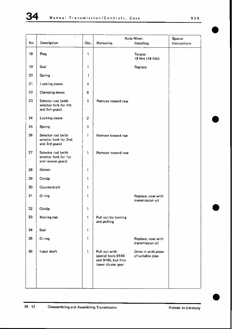
34 Manual Transmission/Controls, Case 926
Note When: Special NO. Description my. Removing Installing Instructions
18 Plug 1 Torque:
19 Nm (14 ftlb)
19 Seal 1 RdG?
20 Spring 1
21 Locking sleeve 1
22 Clamping sleeve 6
23 Selector rod (with 1 Remove toward rear selector fork for 4th and 5th gears)
24 Locking sleeve 2
25 Spring 1
26 Selector rod (with 1 Remove toward rear Selector fork for 2nd and 3rd gears)
27 Selector rod (with 1 Remove toward rear selector fork for 1st and reverse gears)
28 Detent 1
29 Circlip 1
30 Countershaft 1
31 O-ring 1 Replace, coat with transmission oil
32 Circlip 1
33 Bearing cap 1 Pull out by turning and pulling
34 Seal 1
35 O-ring 1 Replace, coat with transmission oil
36 Input shaft 1 Pull out with Drive in with piece special tools 9140 of suitable pipe and 9148, but first lower cluster gear
3‘. 12 Disassembling and Assembling Transmission Printed in Germany

928 Manual Transmission/Controls, Case 34
-
NO.
37
38
39
40
41
42
43
44
45
46
17
18
49
-
Description
Bolt
Lock washer
Reverse shaft
Pinion shaft assy.
Shim
Needle cage
Thrust washer
Reverse gear wheel
Cluster gear
Needle cage
JVasher
Thrust washer
Gal
QW
7
7’
1
1
X
2
1
1
1
2
1
1
1
-
Removing
Note When:
Installing
Torque:
30 Nm (22 ftlb)
Hollow side feces
bearing cover
Turn and remove
bearing unit with
VW 771
Press out with
9148 and P 263
Insert with 9144
Note quantity and If necessary,
thickness for determine again.
installation later Position correctly
Special
Instructions
Torsional lock
faces case opening,
stick on case With a
little grease
Drive in with
special tool
us 8050/9
Printed in Germany VI, 1982 Disassembling and Assembling Transmission 34.13

34 Manual Transmission/Controls, Case 928
DISASSEMBLING AND ASSEMBLING MANUALTRANSMISSION
Disassembling
1. Mount transmission on assembly stand with special
fool 9149 and drain transmission oil.
5. Remove circlip for countershaft and take out countershaft.
6. Remove circlip for input shaft.
2. Remove differential (see page 39 I).
3. Engage 5th gear. drive out roll pin IA1 for shift
finger and only then (when spring is relaxed) split
pin (B) for spring support.
Disassembling order is important, since otherwise
the accelerated split pin IB) could cause injury.
4. Drive out split pins for selector forks and remove
selector rods toward rear (toward differential).
7. Remove bearing cover by turning and pulling.
Remove O-ring and pull out input shaft with
special tools 9140 and 9148.
Note
Always first remove the countershaft and lower
cluster gear to bottom of transmission.
34.14 Disassembling and Assembling Transmission Printed in Germany

928 Manual Transmission/Controls, Case 34
8. Remove pinion shaft mounting bolts, mount special
tool 9144 on the bearing unit and turn this unit
until reverse shaft can be removed with special tool
VW 771.
~~dJ.Jf~?J
c -1
Note
Reverse shafts without threads are driven out from
the inside with a suitable mandrel after removal of
the pinion shaft.
9. Press out pinion shaft with special tools 9148 and
P 263.
A-US1078or40.19
Assembling
1. Stick thrust washer for cluster gear on case with
a little grease.
2. Place assembled cluster gear in case.
3. Drive in assembled input shaft without
synchromesh parts over outer race of grooved
ball bearing against stop with a suitable piece
of pipe or mandrel, applied alternately.
4. Insert O-ring for bearing cover and lubricate
lightly with oil.
5. Install bearing cover and circlip.
6. Swing transmission on assembly stand so that
input shaft faces down.
7. Insert needle cage and thrust washer in input
shaft.
8. Place synchromesh parts for 5th gear on clutch
unit.
a
Printed in Germany - VI, 1982 Disassembling and Assembling Transmission 34.15

34 Manual Transmission/Controls. Case 928
9. Place reverse gear wheel in case as shown in figure.
10. Screw centering pins (locally made) for installation
of pinion shaft in case and install shims S, of
determined thickness and quantity.
11. Mount special tool 9144 on pinion shaft bearing
cover and guide in pinion shaft carefully. Watch
out especially for the 5th gear synchromesh parts
and reverse gear wheel.
Note:
Engage 4th gear to prevent operating sleeve for
4th and 5th gears from slipping.
12. Position reverse gear wheel correctly with a
suitable screwdriver, unscrew centering pins
for bearing unit and turn latter together
with the shims until the reverse shaft can be
installed.
13
14
15.
Turn bearing unit with shims S3 to installed
position, remove special tool 9144 and torque
mounting bolts to 30 Nm (22 ftlb).
Measure distance “2” between input shaft
and pinion shaft (see page 35 15).
Move countershaft to installed position and
install shaft with O-ring, which is given a light
coat of oil. Install snap ring.
A - Centering pins &xally made)
34.16 Disassembling and Assembling Transmission Printed in Germany

928 Manual Transmission/Controls, Case 34
Note:
Assembly can be made easier by turning transmission
in the assembly stand until the cluster gear falls into
its installed position under its own weight.
16. Drive in seal for internal selector rod with
Special Tool US 8050/g.
17. Engage neutral.
18. Install selector rods, selector forks and shift
interlock components.
1 -Plug
2 -Selector rod, 4th and 5th gear
3 - Detent plunger
4 -Spring
5 -Spring
6 - Detent plunger
7 - Selector rod, 1 st and reverse gear
8 - Interlock pin
9 -Selector rod, 2nd and 3rd gear
Printed in Germany - VI, 1982 Disassembling and Assembling Manual Transmission 34.17

34 Manual Transmission/Controls, Case 928
19. Install internal selector rod with shift finger and
springs as shown in figure. Concave surface of
spring faces down to selector rod.
20. Turn internal selector rod 180° with Special
Tool 9155 and install pin for shift finger. The
torsion spring will be under tension in this
position and cavity for pointed screw in internal
selector rod faces left (looking forwardl.
A - Spring (concave surface faces down)
I3 -Spring (only for transmissions with reverse
gear shift lock)
21. Check by shifting through all gears with Special
Tool 9155.
34-18 Disassembling and Assembling Manual Transmission Printed in Germany

928 Manual Transmission/Controls, Case 34 a
6 1
1 -
Note When: Special NO. Description my. Removing Installing Instructions
1 Vent 1
2 Bolt 2 Torque: 9 Nm
3 Washer 2
4 Gear lock 1 Check locking
paw1 for easy
m0”eme”t
5 Leaf spring 1 Position correctly
6 Case cover 1
hinted in Germany - VI. 1982 Disassembling end Assembling Upper Case Cover 34.19 with Reverse Gear Lock

-
a
a
0 -
92x hlanual Tran~nlisrion/C;earr and Shafts 35
TOOLS
NO. Description
Support rail
Mandrel
Special Tool
VW451
VW401
Printed in Germany Disassembling and Assembling Input Shaft 35 - 1

35 Manual Transmission/Gears and Shafts !, 28
a
b /
,i$yY ~-- co .F /
& ~‘ y
‘\ I \ ;i
‘“r P” -.-
a Q,
K I. y- $2,. ,*-, ,g?--
.-;_’ ,“?. ,
RS- 2 Disarsemblinp, and Assembling Input Shaft Printed in Germany
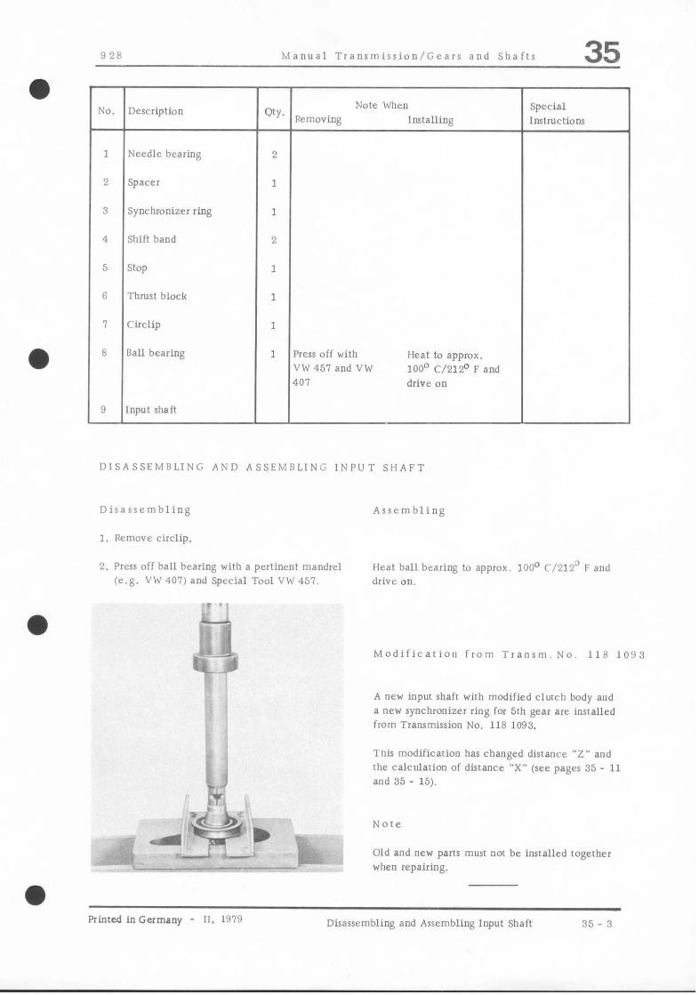
Manual Transmission/Gears and Shafts 35
DISASSEMBLING AND ASSEMBLING INPUT SHAFT
Disassembling
1. Remove circlip.
Assembling
2. Press off ball bearing with a pertinent mandrel (e.g. VW 401) and Special Tool VW 457.
‘. 11
--
Heat ball bearing to approx. 100° C/212” F and drive on.
Modification from Tranrm. No. 118 LO!13
A new input shair with modified clutch body and a new synchronizer ring for 5th gear are installed from Transmission No. 118 1093.
This modification has changed distance “Z” and the calculation of distance “X” (see pages 35 - 11 and 35 - 15).
Old and new parts must nor be installed rogerher when repairing.
a Printed inGermany - 11. 1979 Disassembling and Assembling Input Shaft 35 - 3

928 Manual Transmission/Gears and Shafts 35
TOOLS
1% - b, i. \ x ,
\. ,I
*.* ::,_ ,’ _’
i -“b
-1
; ,g ; ,#?
*
7 f I h ,, ,.
Y, -
1’ I! 1% <.
2 3
r
NO. Description Special Tool Remarks
1 Retainer 9142
2 Support rail VW 457
3 separator us 1103
4 Wrench 9143
a hinted in Germany - VI, 1982 Disassembling and Assembling Pinion Shaft 35 - 5
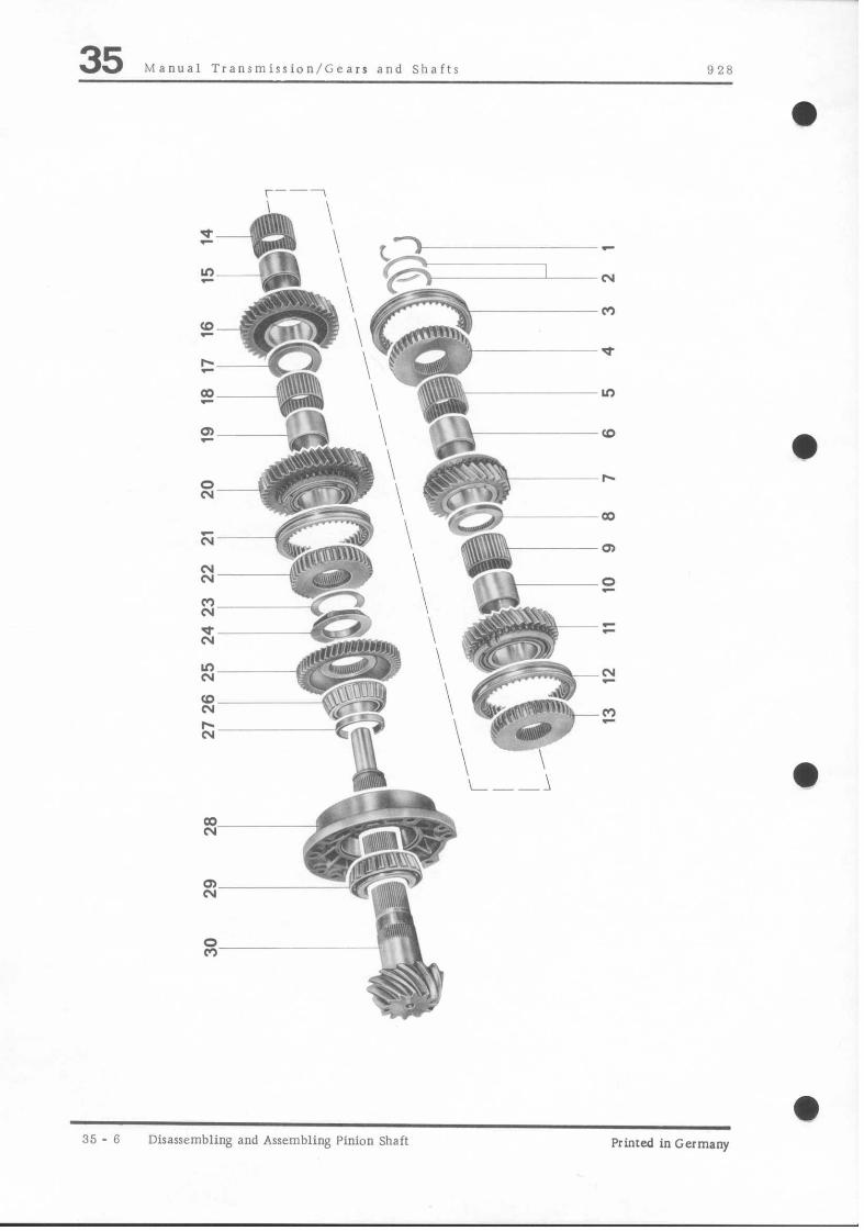
35 Manual Transmission/Gears and Shafts 928
s \ I’ ,,,t“ ’ -
s :.-I$ \ m ,*\,,$!;5;,
it ‘- 7,” ‘<
Ki */ , $
\
\
v;.* \ \
-+*+ L--l - 1*;4\r,. 5; ,, -1 &2 :.
z - g-7 ‘,, , * G,\,V,’
i-s “I c*$$J >’ ,. ‘z
35 - 6 Disassembling and Assembling Pinion Shaft Printed in Germany
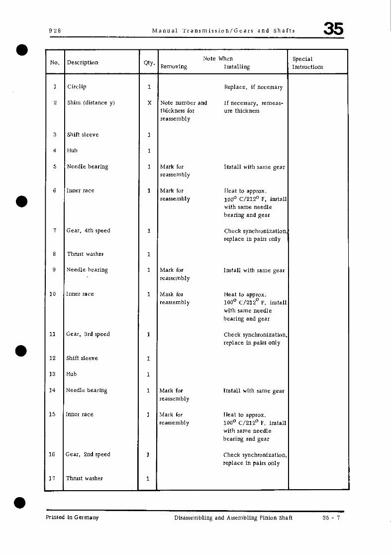
928 Manual Transmission/Gears and Shafts 35
NO. Description Qty. Note When Special
Removing Installing Instructions
1 Circlip 1 Replace, if necessary
2 Shim (distance y) X Note number and If necessary. remeas- thickness for ure thickness reassembly
3 Shift sleeve 1
4 Hub 1
5 Needle bearing 1 Mark for Install with same gear reassembly
6 Inner race 1 Mark for Heat to appmx. reassembly loo“ C/212’ F, install
with same needle bearing and gear
7 Gear, 4th speed 1 Check synchronization. replace in pairs only
8 Thrust washer 1
9 Needle bearing 1 Mark for Install with same gear reassembly
.O Inner race 1 Mark for Heat to approx. reassembly 100’ C/ZIZ” F. install
with same needle bearing and gear
.l Gear. 3rd speed 1 Check synchronization. replace in pairs only
~2 Shift sleeve 1
3 Hub 1
4 Needle bearing 1 Mark for Install with same gear reassembly
5 Inner race 1 Mark for Heat to approx. reassembly 100’ C/212’ F, install
with same needle bearing and gear
6 Gear, 2nd speed 1 Check synchronization. replace in pairs only
7 Thrust washer 1
Printed in Germany Disassembling and Assembling Pinion Shaft 35 ^ 7

35 Manual Transmission/Gears and Shafts 928
Note When: Special
NO. Description QW. Removing Installing Instructions
18 Needle cage 1 Mark for reassembly Install with same
gear
19 Inner race 1 Mark for reassembly Heat to approx.
100 “C/212 “F,
install with same
needle bearing and
gear
20 Gear, 1 St speed 1 Check rynchroniza-
don. replace in pairs
0llly
21 Shift sleeve 1
22 Guide sleeve 1 Flat surface on
side flank faces 1st
gear
23 Shim (distance XI X Note quantity and If necessary,
thickness for remeasure thickness
reassembly
24 Lock nut 1 Tighten to specified
torque, lock by
staking
25 Reverse gear 1 Cavity faces lock
nut
26 Tapered roller bearing 1 Press off together Heat to approx.
inner race with bearing cover 100 “C/212 OF and
drive on
27 Shim 1
28 Bearing cover 1 Press off Replace only
complete with
tapered roller
bearing and shim
29 Tapered roller bearing 1 Press off with a Heat to approx.
inner race suitable separator 100 “Cl212 “F and
drive on
30 Pinion shaft 1 Adjust if necessary.
Note pair number
35 .8 Disassembling and Assembling Pinion Shaft VI, 1982 Printed in Germany

928 Manual Transmission/Gears and Shafts 35
DISASSEMBLING AND ASSEMBLING PINION SHAFT
Disassembling
1. Press gears and inner races off of pinion shaft with
special tool VW 457 and a suitable support.
: :-~ , “Iv,,
I. :N”‘;
,,,.(.
.+...,.. -.1 .~<,~rll.n i
%-. d
A *bp..d I
\ /~
A -Standard U-steel (U 200) approx. 260 mm long
2. Unscrew lock nut with special tools 9142 and 9143.
’ $$e:. -,*. Pi
, $ ,’
i .; I\
& i, ++A ,-j$ _ ;
-a. ! i’
( _i- -.. I.%. ‘+ t ;f’
..+ ,/4 +
3. Press off bearing cover with a suitable press tool.
P ’
I f--1 ;“I
$&$q ~,, M -ai --1L>- ._I-& --
4. Press off large tapered roller bearing inner race with a suitable sewrator.
Printed in Germany - VI, 1982 Disassembling and Assembling Pinion Shaft

35 Manual Transmission/Gears and Shafts 928
Assembling
1. Tighten lock nut to specified torque with Special Tools 9142 and 9143.
2. Lock lock nut by staking collar
3. Press assembled gear set together with an appropriate piece of pipe (e.g. VW 519). Approx. 5 tons of pressure.
35 - 10 Disassembling and Assembling Pinion Shaft Primed in Germany
F s . : ..‘.$ 5’ -‘._ ( p i ;
,*I& zlr!%
y&y
$\K :t

928 Manual Transmission/Gears and Shafts 35
DETERMINING SHIM THICKNESS “X” OF PINION SHAFT LO& NUT
N.ote
To guarantee perfect running of spur gears from pinion shaft and countershaft. shims must be used
on the pinion shaft.
A - Distance from pinion head to bearing surface of lock nut
B - Distance A + r (pinion shaft deviation)
r -Pinion shaft deviation (e. g, N 12)
1 - Design specification
Transmission Type G 28.03 108.85 mm up to transm. no. 118 1092
108.70 mm from transm. no. 118 1093
Transmission Type G 28.05 110.70 mm from transm. no. 110 5001
Printed in Germany VI, 1982 Determining Shim Thickness “X” 35.11

35 Manual Transmission/Gears and Shafts 928
Measuring Procedures
1. Measure distance “A” with a sliding calipers.
2. Work out distance “B” B=A+r
3. Work out distance “X” (Type G 28.03 up to Transm. No. 118 1092) X = 108.85 - 8
4. Work out distance “X” (Type G 28.03 from Tranrm. No. 118 1093) X = 108.70 - 8
5. Work out distance “X” (Type G 28.05 from Transm. No. 110 50011 x=110.70--B
Example (Type G 28.03 up to Transm. No. 118 1092)
Distance “A” = 106.90 Distance’%” = A+ r
A = 106.90mm +r = 0.12 mm
107.02 mm
Distance “X” = 108.85 - 9
108.85 mm - 107.02 mm
1.83 mm
a
35-12 Determining Shim Thickness “X” Printed in Germany

Manual Transmission/Gears and Shafts 35
DETERMINING SHIM THICKNESS “Y” AT GEAP SET END
Note 3. Install a shim with maximum thickness “Y” to
take up all play. Since a circlip on the pinion shaft prevents axial
movement. gear set must be adjusted to take up all play between gear set and circlip.
I
1. Press assembled gear set together with an
appropriate piece of pipe (e.g. VW 519). Approx. 5 tons of pressure.
2. install new circlip in groove
Primed in Germany Determining Shim Thickncsr “Y” 35 - 13

Manual Transmission/Gears and Shafts 35 MEASURING DISTANCE “Z” BETWEEN INPUT SHAFT AND PlNlON SHAF’I
Since the new Porsche synchronizing system does not employ circlips, ir is important to make sure that distance “2” is maintained between end face of inpur shaft and 4rh/5rh speed hub on pinion shaft,
Dirrance “Z” 0.2 to 0.3 mm up to transm. no. 118 1092 0.4 to 0. 6 mm from rransm. no. 118 lo!13
1. Measure distance ‘7” between input shaft and Note hub with a feeler gage.
Do not measure distance between synchronizer ring and shift sleeve or clutch body and shift sleeve.
2. If distance “2” is nor 0. 2 IO 0. 3 mm or 0.4 to 0. 6 mm. disassemble pinion shaft again and correcI shim thickness “X”. Of course, it will also be necessary to redeter- mine shim thickness ‘7’” on end of pinion
shaft.
hinted in Germany - Il. 1919 Measuring Distance “Z” Between Input Shaft and Pinion Shaft
35 - 15

928 Manual Transmission/Gears and Shafts 35 DISASSEhlBLING AND ASSEMBLING SYNCHRONIZERS
The transmission of the 9’28 is equipped with modified Porsche synchronization for all forward speeds. One of the changes is the “mission of circlips. which previously were used to keep the synchronizing ring thrust blocks and shift bands from moving axially. In the new system this is accomplished by a shift sleeve with beveled flanks.
1st Gear
Synchronizer ring: Thrust block: Shift band:
stop:
Installation Note:
, \ , \ ! \ “,
2nd Gear
Synchronizer ring: Thrust block: Shift band: stop:
Installation Note:
3rd Gear
Synchronizer ring: Thrust block:
Shift band: stop:
1 groove on face 2 bevelled flanks
Asymmetrical shift band
Two straight flanks
Short side of shift band must be to right of thrust block
2 grooves on face or red dot 2 bevelled flanks Symmetrical shift band 1 straight. 1 bevelled flank
Bevelled side of stop must face to right as seen from top view
2 grooves on face or red dot 2 bevelled flanks
2 separate shift bands Bevelled flanks
Printed in Germany Disassembling and Assembling Synchronizers 35 - 17

35 Manual Transmission/Gears and Shafts 928
4th Gear:
Synchronizer ring: No grooves
Thrust block: 2 bevelled flanks
Shift band: 2 separate shift bands
stop: Bevelled flanks
Note: See below
5th Gear:
Synchronizer ring: No grooves
Thrust block: 2 bevelled flanks
Shift band: 2 separate shift bands stop: Bevelled flanks
Note: See below
Fifth gear synchronizer ring is identical with fourth Fifth gear synchronizer ring cannot be used on 4th
gear synchronizer ring up to Transmission No. 118 1092. gear wheel beginning with Transmission No. 118 1093,
35-18 Disassembling and Assembling Synchronizers VII. 1983 Printed in Germany
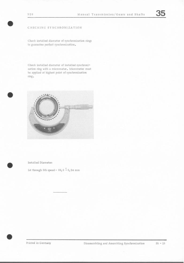
92X Manual Transmission/Gears and Shafts 35 a
CIIECKING SYNCHRONIZATION
Check installed diameter of synchronization rings to gilarantee perfect synchronization.
Check installed diameter of installed synchroni- zation ring with a micrometer. Micrometer must be applied at highest point of synchronization ring.
a Installed Diameter:
1st through 5th speed = 86.0 t_ 0.24 mm
a Printed in Germany Disassembling and Assembling Synchronization 35 - 19

35 Manual Transmission/Gears and Shafts 928
a
a
a
a 35 - 2” Disassembling and Assembling Synchronization Printed in Germany

928 Manual Transmission/Gears and Shafts 35 a
TOOLS
1 support rail
2 Mandrel
Special Tool Remarks
VW 451
VW 407
a Printed in Germany Disassembling and Assembling Countershaft Hub/Gears 35 - 21

35 Manual Transmission/Gears and \I!..!I, 928 .-__
a 35 - 22 Disassembling and Assembling Countershaft Hub/Gears IV. 1980 - Primed inGermany

Manual Transmission/Gears and Shafts 35
No. Description Qv. Nore When Special
Removing Insralling lnstrucrions
1 Needle bearing 2
2 Washer 1 Only for rransm. type 28.05
3 Circlip 1
4 Circlip 1
5 5th gear 1 Press off with Replace only in pairs VW 401 and (with input shaft), VW 457 large shoulder faces
spacer
6 spacer 1
7 4th gear 1 Press off with Replace only in pairs. VW 407 and large shoulder faces VW 457 3rd gear
8 3rd gear 1 Press off with Replace only in pairs. VW 407 and small shoulder faces VW 451 stop
9 Countershaft hub 1
DlSASSEMBLING AND ASSEMBLING COUNTERSHAFT HUB/GEARS
Disassembling
1. Remove circlip,
2. Press off gears (3rd. 4th and 5th) with a suitable mandrel (e.g. VW 407) and Special Tool VW 457
Assembling
Heat gear to approx. 100” C/212” F and install to correct position.
‘I -
Printed inGermany - IV, 1980 Disassembling and Assembling Countershaft Rub/Gears
35 - 23

928 Automatic Transmission / Controls. Case 37
TOOLS
. ,
,/‘ T
r I I ,_- z ---
No. Description Special Too1 Remarks
1 Removal plate 9163
2 Chain 9164
Primed in Germany - I. 1978 Removing and Installing Transmission 37 - 1
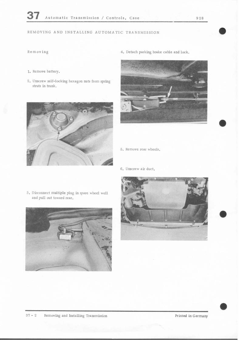
37 Automatic Transmission / Controls. Case 928
REMOVING AND INSTALLING AUTOMATIC TRANSMISSION
Removing
I. Remove battery.
2. Unscrew self-locking hexagon nuts from spring struts in trunk.
3. Disconnect multiple plug in spare wheel well
and pull o”t toward rear.
4. Detach parking brake cable and lock.
b. ~, ,., “‘.
n 7: -- -.,
pf, c’ ‘+.@$g &q
: ,~frr;“r‘~~,.*~,. 7.1 .
)..-, ,__ _. .. i-“’ ‘- ..-;;‘::,$ ~~:~
F”, / ’̂ ! .
5. Remove rear wheels.
6. Unscrew air duct.
31 - 2 Removing and Installing Transmission Printed in Germany
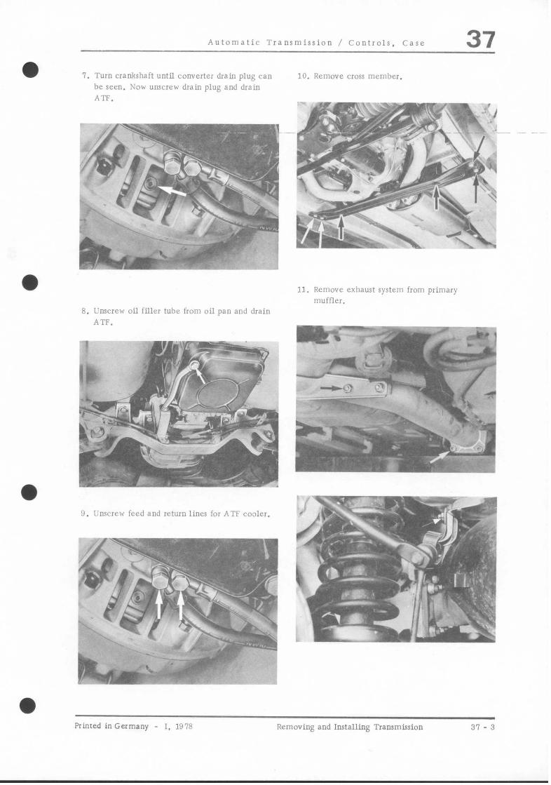
Automatic Transmission / Controls. Case 37 7. Turn crankshaft until converter drain plug can
be seen. Now unscrew drain plug and drain ATF.
8. Unscrew oil filler tube iron1 oil pan and drain ATF.
/
f
u :
i ..-FY~, i i’ i , . . *‘it.- ,_.
4:
~ . .?t .’ : ‘. ‘\ ; -;&- ,
-.‘T
;~fp ‘~ -;&:-:I
. I;.;. ‘G.. !
9. L~nscrew feed and stun Iincs for ATF conler.
10. Remove CIOSS member.
.- i”
;dmF$!~~~, ‘1 . ;fl I . - L .R-- lm b rc -.<.. d” ’ ,&y
.-&.gy, ,-, ‘G, I I. “,‘;-- : ..,., 7% -. \ -a 1 11. Remove exhaust system from primary
lmyir-m,,~ -rj .e,.. _~
zmF= -,
1 I “c”“-* ‘x
-, --. .i. I
4
!
Printed inGermany - 1. 1978 Removing and Installing Transmission 31 - 3
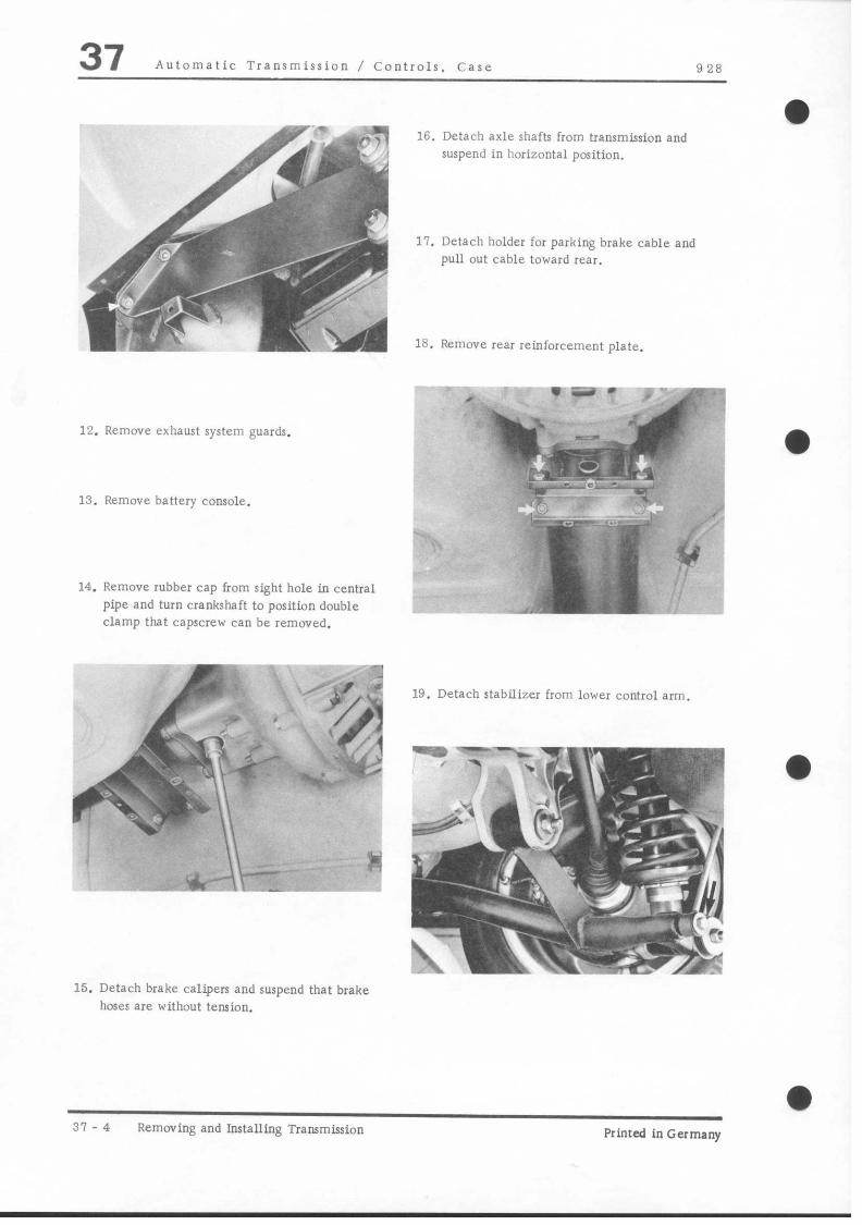
37 Automatic Transmission / Controls. Case 928
12. Remove exhaust system guards.
13. Remove battery console.
14. Remove rubber cap from sight hole in central pipe and turn crankshaft to position double clamp that capscrew can be removed.
15. Detach brake calipers and suspend that brake
hoses are without tension.
16. Detach axle shafts from transmission and suspend in horizontal position.
Il. Detach holder for parking brake cable and pull out cable toward rear.
18. Remove rear reinforcement plate.
1 -I
.
_ . wEI-
a % .- -
_r- .: ~_ 4
$ .$
19. Detach stabilizer from lower control arm.
31- 4 Removing and Installing Transmission Printed 1” Germany
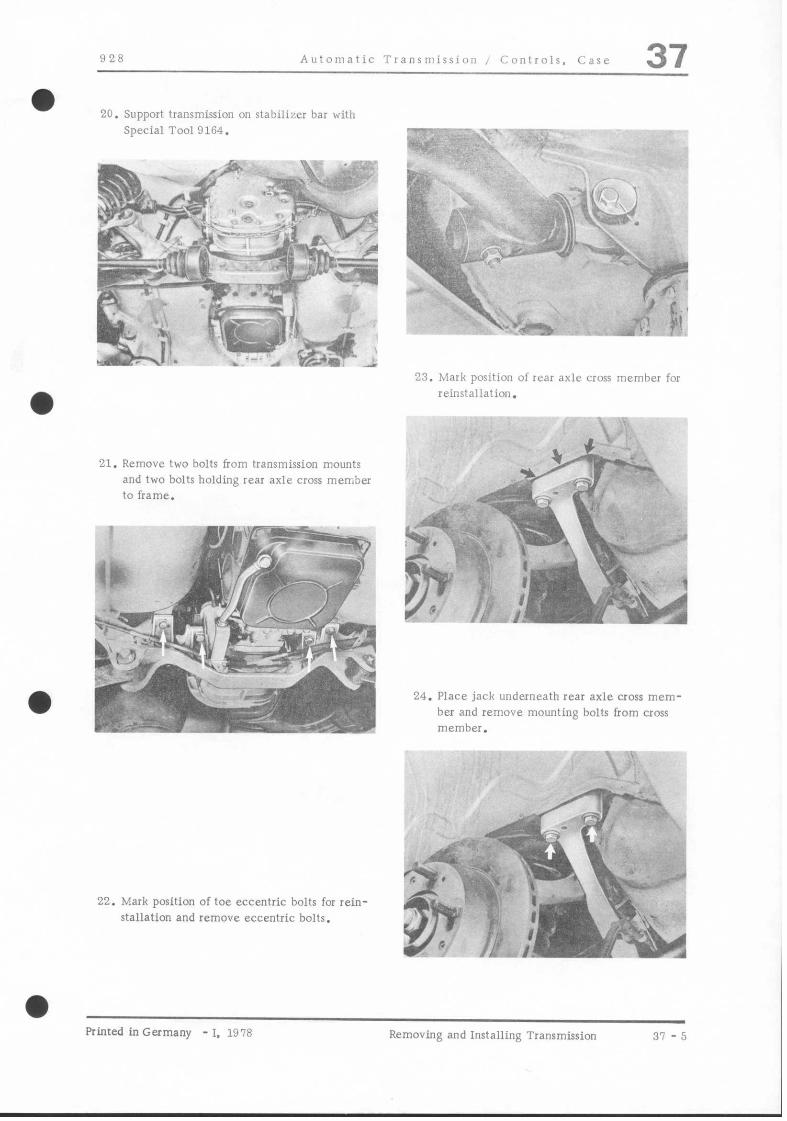
928 Automatic Transmissim , ~;onlroir, Care 37
20. Support trammission on stabilizer bar with Special Tool 9164.
21. Remove two bolts from transmission mounts and two bolts holding rear axle cross member to frame.
e-.,9-. . -.“~=I
23. Mark position of fear axle cross member for reinstallation.
24. Place jack underneath rear axle cross mem- ber and remove mounting bolts from cross
22. Mark position of toe eccentric bolts for rein- stallation and remove eccentric bolts.
hinted in Germany - I, 1978 Removing and Installing Transmission 37 -5

37 Auromaric Transmission / Controls, Case 0 28
25. LOVE, rear axle carelully and be careful ihar spring IITUIS, cross member and hearing hrackers do rnor tilt.
NOiC
A second person is required for removal of
rear axle.
26. Mounr Special Tool 9163 on universal tram- lnission lift and place underneath transmis- sion.
27. Lift transmission and detach Special Tool 9164.
28. Lower rransmission a lirrle, detach selector lever cable and disconnect cable sleeve.
:O. Rctnove six bolls of central robe This re- quires lowering rransmission as fas a* possible
,*-F ,.I”
When lowering rransmission. be careful tha: check valve for air injection does nor damage brake line.
29. ml1 off vacuum line from vacuum modula- to1 and press our of holders. Detach transmis- sion cable and remove holder for guide tube.
31. Pull transmission out of coupling splines and lower carefully.
37 - 6 Removing and Installing Transmission ~1, um Primed inGermany

928 Auromaric Transmission / Conrrols. Case 37 FRONT CONVERTER HOI!SING. EXCHANGING
Before installing new automatic transmission/final drive assembly inro vehicle. front convener housings mu1 be exchanged berween new and old units. This is to maintain factory adjustmenr between drive shafr coupling and transmission input shaft.
Perform following sLeps:
1. Loosen 6 bolts (2) attaching drive plate IO rorque converter (1) through opening (arrow).
2. Remove 8 bolts holding front convener housing
(A).
3. Exchange front converter housings only.
4. Tighten converter housing bolts to 1.9 - 2. 3 mkg (14 - 17 fr lb).
5. Tighten drive plate bolts to 3. 2 - 3.9 mkg
(23 - 28 ft lb).
Printed in Germany - II, 1979 Exchanging Front Converter Housing 37-6a
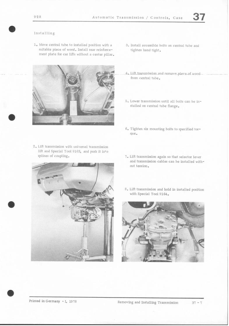
-
a
928 Automatic Transmission / Controls. Case 37
Installing
1. hlove central tube to installed position with a suitable piece of wood. Install rear reinforce- ment plate for car lifts witbout a center pillar.
2. Lift transmission with universal transmission lift and Special Tool 9163. and posh it in’o splines of coupling.
-7
---m
11 - xe * p-&-:-~ ~.p4’“‘
i _li -.=,- _ ?&I$ \-.:\: 0 ‘\-~..b ‘,.& .J <- :“ ‘_ , I. I’ a’,,, 1 ._r __ 5, * .- b-
I ! i, I ;? : _ ‘. I~ d ‘--- ,J
3. Install accessible bolts on central illbe and tighten hand tight.
-1,~Lift~transmission~aod re.move..pieceof rend from central tube.
5. Lower transmission until all lbolts can ibc in- stalled on central tube flange.
G. Tighten six mounting bolts to specified tor-
que.
1. Lift transmission again so that selector lever and transmission cables can be installed with- out tension.
8. Lift transmission and hold in installed position with Special Tool 9164.
a Printed in Germany - 1. 1978 Removing and Installing Transmission 37 - 7

37 Automatic Transmission / Controls. Case 928
9. Push up wire harness through opening in spare wheel well and install rubber pmm~i.
13. Mount transmission on cross member and tighten all bolts to specified torque.
10. Lower universal transmission lift. Note: Watch marks for correct reins+allation.
11. Position rear axle and tighten all bolts except for the two transmission mount bolts.
A second person is required to install rear axle.
12. Lift transmission and detach Special Toot
9164.
a
37 - 8 Removing and Installing Transmission II, 1970 - Printed in Germany
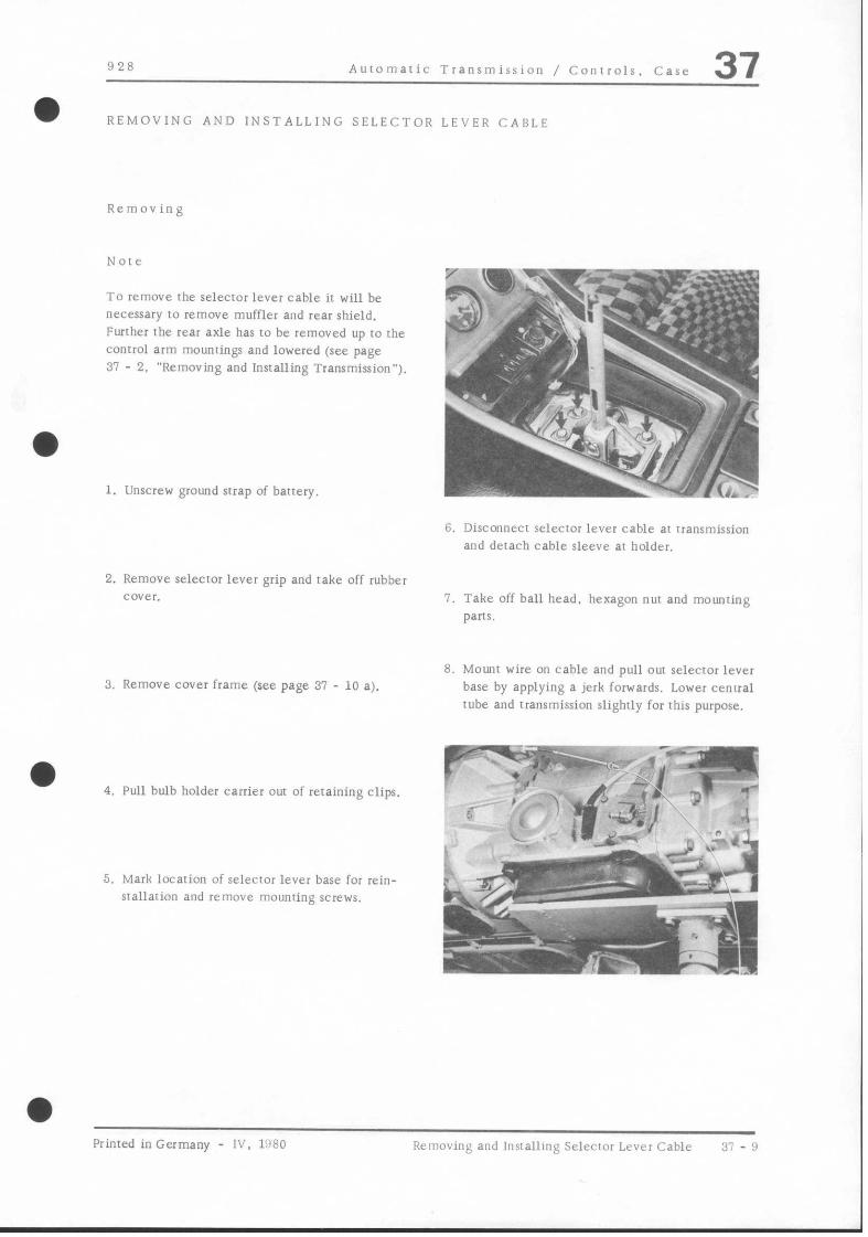
828 Automatic Transmission / Controls. Case 37 a REMOVING AND INSTALLING SELECTOR LEVER CABLE
Removing
Norc
To remove the selector lever cable it will be necessary to remove muffler and rear shield. Further rhe rear axle has IO be removed up IO the control arm mounrings and lowered (see page 31 - 2. “Removing and Installing Transmission”).
1. Unscrew ground strap of battery.
6. DisconnecI selccror lever cable ar transmission and derach cable sleeve ar holder.
2. Remove selector lever grip and rake off rubber cover.
3. Remove cover frame (see page 31 - 10 a).
4. Pull bulb holder carrier out of retaining clips.
5. Mark locarion of selector lever base for rein- srallaiion and remove mounting screws.
I. Take off ball head. hexagon nur and mounting part*.
8. Mow wire on cable and pull out selecror lever base by applying a jerk forwards. Lower cenual tube and transmission slighrly for this purpose.
Printed in Germany - IV, 1’180 Removing and lnsralling Selector Lever Cable 37 - !$

37 Auromaric Transmission / Controls. Case 928
w--v . _ ‘.I :r; .‘a & -i’ .,,- 1 y&
.I “ix ,_ ,i . ., .>
5. lnsrall cover frame and place seleaor lever at “N”.
If light opening of gate and letter “N” are nor exacrly opposite each other in cover frame. remove cover frame again and reposition selector lever base in slots.
24 :’ ii “$ )’
p. ,, ,pq&;yi’~ F
9. Remove cable circlip from selecror lever and detach cable sleeve at selector lever base.
6. Adjust selector lever cable and check adjust- menI (see pages 31 - 11 EO 31 - 12).
lnslalling
1. Arrach cable sleeve on selecror lever base, tightening the hexagon nut carefully.
2. Push cable on 10 selector lever pin and insrall circlip.
3. Mount wire. pulled forward during removal, on cable and pull cable roward rear.
Selector lever cable musk be routed underneath a meral tab, which is mounted on convener
housing with a hexagon screw.
4. lnsrall selector lever base (warching mark) and tighten the mounring screws.
31 - 10 Removing and lnsralling Selecror Lever Cable Primed in Germany

928 Automatic Transmission / Conrrols. Case 37 a REMOVING AND INSTALLING SELECTOR LEVER COVER FRAME
a
At the beginning of standard production covet frames without locks were used. These frames can be pried out of the center console wirh a suitable screwdriver.
Removal of the new version with locks, on rhe other hand, requires unlocking both locking bars
1 -
a 2-
ATIAYb?--.
1 2
c_ n f.
,.'.
*
pm: -- I,,, bc:+-
. '
Jl p. , .-. ,/ .2'
/ ., ,r
\
_-y: ~ .
L
Cover frame without lock (old version) Cover frame wirh lock (new version)
3. Move selector lever to position “R”. disconnect gate and push forward as far as possible,
4. Push front locking bar forward against stop with a suitable tool (e. g. scribe).
5. Move selector lever to position “P” and press out cover frame carefully with a suirable screw- driver applied at the left rear comer.
Removing
1. Remove selector lever handle and rake off rubber cover.
2. Move selector lever to position “1” and push rear locking bar forward against stop with a suitable tool (e.g. scribe).
hinted in Germany - IV, 1980 Removing and Installing Selectot Lever Cover Frame
37 - 10 a

37 Automatic Transmission / Conrrols, Case 928
6. Move selector lever 10 position “N” and remove frame inclined toward rear.
Installing
1. Move selector lever to position “2”.
2. Push gate in frame forward all the way.
3. Install cover frame in correct position and
move selector lever to position “P”.
4. Push rover frame forward and move right side to correct installed position (this is done by lifting left rear comer slightly and pushing down on right side).
5. Push down on left rear comer until frame firs
in center console correctly.
6. Move selector lever between “R” and “P”, connect gate on selector lever and push for- ward.
1. Push front locking bar toward rear until ir engages.
8. Move selector lever to position “2” and push rcar~‘~king-~mriuward~rear umii ir engages.
A - Locked B - Unlocked
9. Attach gate in selector lever. install rubber cover in correct position and install selector lever handle.
10. Move selector lever in and out of all positions and make sure that cover frame fits correctly.
37 - 10 b Removing and Installing Selector Lever cover Frame
Printed in Germany

928 Automatic Transmission / Controls. Case 37
ADJUSTING SELECTOR CABLE
b cd
1. Place selector lever in & 4. Adjust cable so that ball socket attaches to operating lever without tension.
2. Detach cable from operating lever (on trans.).
3. Place selector operating lever (on trans.) in position.
Printed inGermany - 11. 1979 Adjusting Selector Cable 37 - 11

37 Automatic Transmission / Controls. Case 928
CHECKING SELECTOR CABLE AND BACKUP LlGHT SWITCH OPERATION
Note 7. Move lever to p-Turn off engine. Correct adjustment of selector lever and selector
cable is absolutely necessary for proper ope- ration of transmission.
8. Adjust selector cable if necessary.
1. Place selector lever in J& Apply parking and foot brakes. Start engine and idle at about 1000 - 1200 rpm.
2. Move lever to& Engine speed must drop as gear engages. Backup lights must light.
3. Move lever top- Engine speed should increase as reverse gear disengages.
4. Move lever to&Engine speed must drop as gear engages.
5. Move lever to i& Engine speed should in. crease as reverse gear disengages.
6. Move lever to & Engine speed should drop as gear engages.
31 - 12 Checking Selector Cable and Backup Light Switch Operation
Printed in Germany

928 Auromatic Transmission / Controls. Case 37
REMOVING AND INSTALLING ACCELERATOR CABLE
Removing
1. Detach cable at transmission lever. Unscrew ball socket and locknur. Pull off rubber grommer.
2. Detach cable at throttle valve lever.
3. Remove circlip for cable sleeve and pull cable WI forward. being careful nor IO bend cable.
Ad 4 >iS> i. fy’ :I
lnsralling
Adjust cable (see page 37 - 14).
Printed in Germany - 11. 1979 Removing and Installing Accelerator Cable 37 - 13

37 Auromaric Transmission / Controls. Case 928
ADJUSTING THROTTLE PRESSURE CABLE
1. Detach cable ar trans. lever.
2. Adjust lever with adjusting bolt A after loosening clamping bolt B so rhz cable can be attached wirhour tens& or free play.
Caurion
If clamping bolt B is loosened for adjurrmenrs.
under no circumstances should bolt be tightened againsr stop inside transmission (damager opera- ting lever). Use second wrench.
A - adjusring bolt B - clamping bolt
Ball socket of cable musr be screwed on threads
approx. 6 mm (l/4 in.).
When cable is adjusted correcrly. trans. lever wave1 will be approx. 33 mm (1 5/16 in.) as accelerator pedal is depressed from idle IO full throrrle (not kickdown).
37 - 14 Adjusting Throttle Pressure Cable Printed in Germany

-
a
a
9 28 Auromaric ‘Transmission I Conrrols, Case 37
CHECKING NEUTRAL/PARK STARTING REM01 ING NELlTRAL/PARK STARTING
SWITCH SWITCH
Starter should only operate in P or _N posirions with - properly adjusted swirch.
1. Place selector lever in N position
2. Disconnecr electrical plug
ADJUSTING NEUTRAL/PARK STARTING 3. Remove clamping bolrz and pull operaring SWITCH lever 1 (wirh attached driving dog) off shafr 5
1. Move selector lever [o posirion N. 4. Remove swirch mounting bolts and withdraw
switch.
2. Loosen adjusting screw.
INSTALLING NEUTRAL/PARK STARTING 3. Inserr 4 mm dia. pin from I!S 8030 tool set SWITCH
through drive dog into locaring hole in case.
1. lnsrall switch and mounting bolts for same.
2. Place operating leveri (with attached driving dog) onto shaft 5.
3. Inseri lugs of driving dog into swirch.
4. lnserr clamping bolr 3 inro operating lever 1 and righten nur.
1 = operating lever 2 = adjusringscrew
3 = clamping bolt 4 = locaring pin (from US 8030 rool set) 5 = shaft
5. Connect elecrrical plug.
6. Adjust switch.
4. Tighten adjusting screw. Remove locating pin
5. Check wherher engine can be started with selector lever in N 01 P positions. - -
Printed inGermany - II. 1919 Neurral/Park Srarring Swircii 37 - ,5
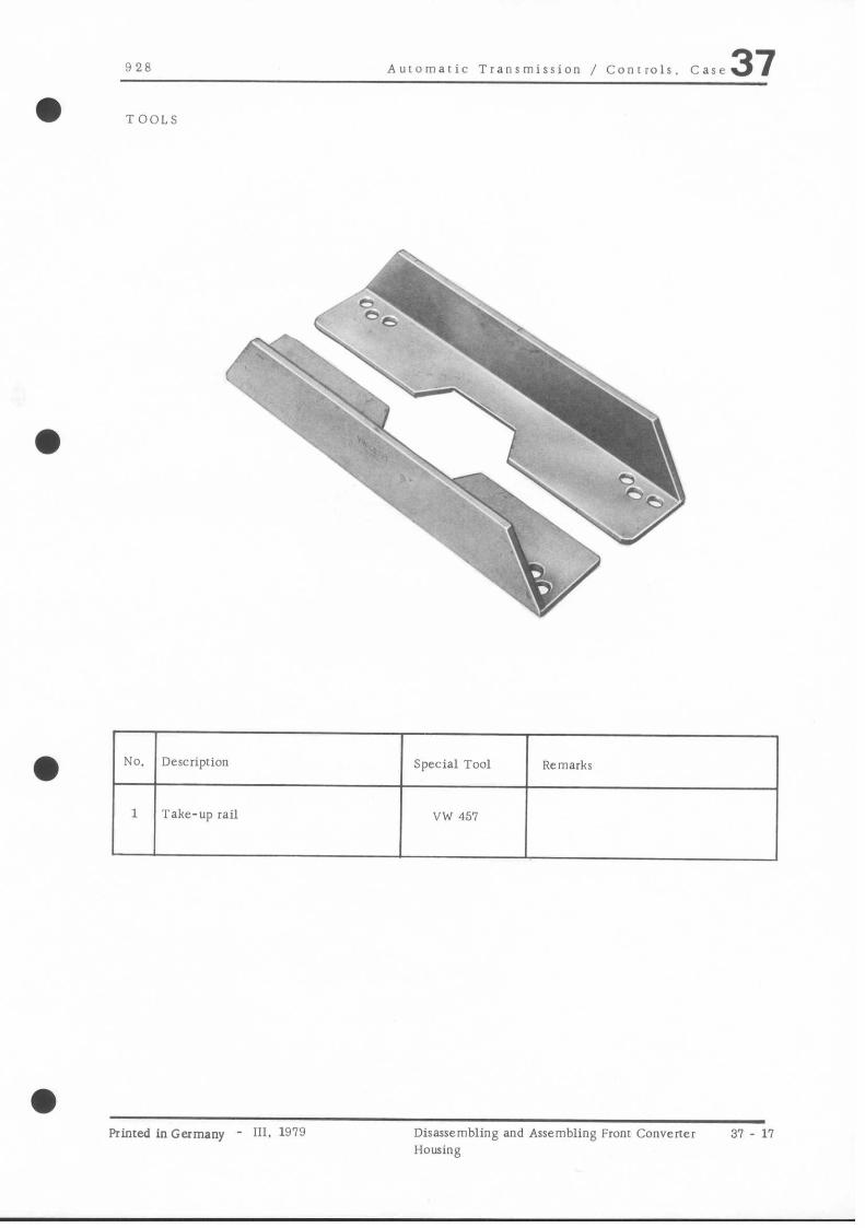
928 Auromaric Transmission / Conrrolr. Case 37
TOOLS
l No. Description Special Tool Remarks
1 Take-up rail VW 451
Printed inGermany - 111. 1979 Disassembling and Assembling From Converter 31 - 11
Housing
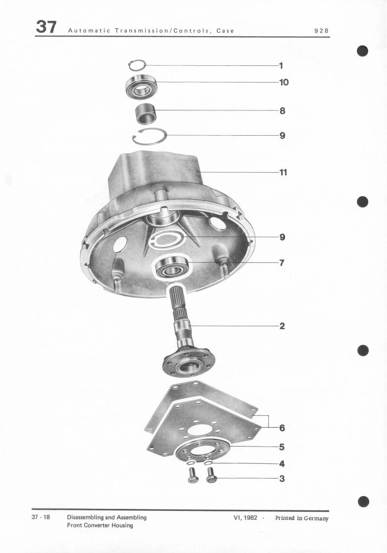
37 Automatic Transmission/Controls. Case 928
37 - 18 Disassembling and Assembling Front Converter Housing
VI, 1982 - Printed in Germany
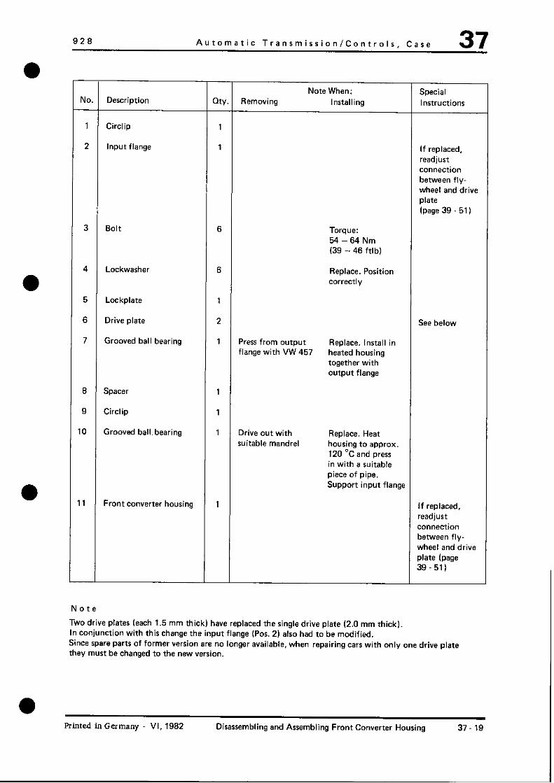
928 Automatic Transmission/Controls, Care 37
Note When: Special NO. Description Qfy. Removing Installing Instructions
1 Circlip 1
2 Input flange 1 If replaced, readjust connection between fly- wheel and drive plate (page 39 .51)
3 Bolt 6 Torque: M-64Nm (39 - 46 ftlb)
4 Lockwasher 6 Replace. Position correctly
5 Lockplate 1
8 Drive plate 2 See below
7 Grooved ball bearing 1 Press from output Replace. Install in flange with VW 457 heated housing
together with output flange
8 Spacer 1
9 Circlip 1
0 Grooved balls bearing 1 Drive out with Replace. Heat suitable mandrel housing to approx.
120 ‘C and press in with a suitable piece of pipe. Support input flange
11 Front converter housing 1 If replaced, readjust connection between fly- wheel and drive plate (page 39-51)
Note
Two drive plates (each 1.5 mm thick) have replaced the single drive plate (2.0 mm thick). In conjunction with this change the input flange (Pas. 2) also had to be modified. Since spare parts of former version are no longer available, when repairing cars with only one drive plate they must be changed to the new version.
Printed in Germany VI, 1982 Disassembling and Assembling Front Converter Housing 37-19
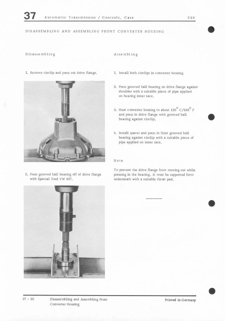
37 Automatic Transmission / Controls, Case 928
DISASSEMBLING AND ASSEMBLING FRONT CONVERTER HOUSING
Disassembling Assembling
1. Remove circlip and press WI drive flange.
9 i .B q$i@ 1
! . .
2. Press grooved ball bearing off of drive flange with Special Tool VW 457.
1. lnstall both circlips in converter housing.
2. Press grooved ball bearing on drive flange against shoulder with a suitable piece of pipe applied on bearing inner race.
3. Hear converter housing to about 120’ C/240’ F and press in drive flange with grooved ball bearing against circlip.
4. lnstall spacer and press in front grooved ball bearing against circlip with a suitable piece of pipe applied on inner race.
To prevent the drive flange from moving out while pressing in rhe bearing, it must be supported from underneath with a suitable thrlsr pad.
31 - 20 Disassembling and Assembling Front
Converter Housing Printed in Germany

9 2 8 Automatic Transmission / Conrrols. Case 37
TOOLS
P-zry Ik -2 ,s ,,.’ .I
I ?
NO. Description Special Tool Remarks
I Knurled head bolt 9303
a
Printed inGermany - 111. 1979 Removing and Insralling Final Drive Housing and Rear Converter Housing
37 - 21

37 Automatic Transmission / Controls. Care 128
/,q; -‘ ‘D
$’ lr ;;r\
0
Lh rl+
‘j i 6’1.- 1’
6
L&$gzz&;51; 2
ty& I--F -- ;yv# ‘-3.g : _’ 0- Q
-fZ~fpFgi&: +y- \-; ‘L-i 0?7- I- .--
37 - 22 Removing and lnntalling Final Drive Housing and Rear Converter Housing
Printed in Germany

928 Auiomatic Transmission / Conrrols. Case 37
Jo. Descripliou
1 Vacuum box
Xute When my.
Special Removing Installing Insrructionr
1 Check leq+h of pressure pin wilt1 ‘3303 install with Omnifir Rapid Red M. Coat threads with Hyloma
2 BOli 10 Tighten to specified rorque
3 washer 10
4 Race I Pull out with 2 approx. 60 mm long bnlrs
5 Final drive housing 1
6 Piston 1
7 Spring 1
8 O-ring 1 Replace. Coat with ATF
Y Cenrrifugal gavernor 1
10 Bolt 2 Tighten to specified rorqw
11 Washer 2
12 Screw 1 Tighten to specified rorque
13 Washer 1
14 Modulation pressure 1 Do not loosen 01 Check valve for
valve housing maladjust adjusting easy nmvement
screw for bimetal afrer righrening
spring mounring screws
Primed inGermany - 111. 1979 Removing and hwalling Final Drive Housing
and Rear Converter Housing 37 23
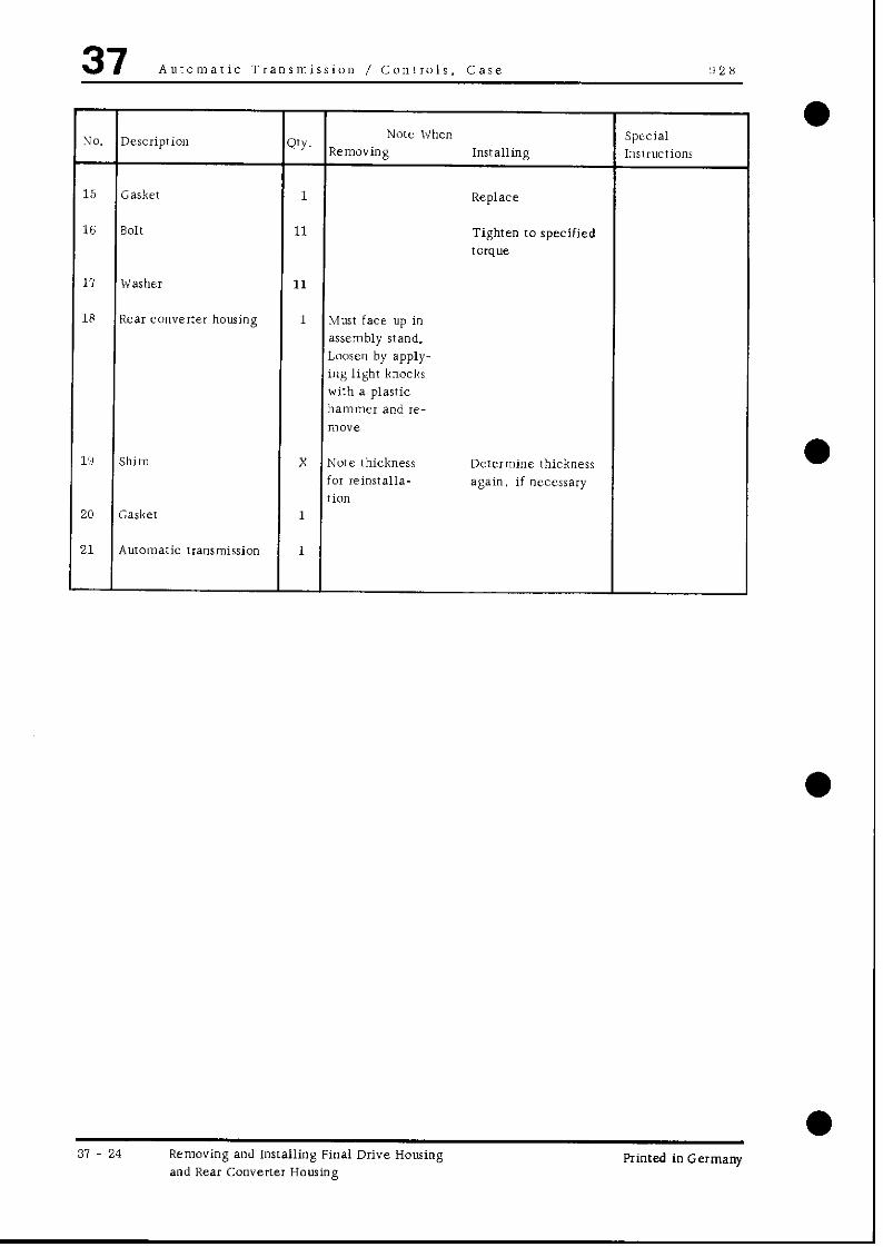
37 Automatic Transmission / Conirols. Case ‘11 2 8
vo. Descriprion WY. Note When Special
Removing Installing Insuuctions
15 Gasker 1 Replace
16 SOIt 11 Tighten IO specified torque
17 Washer 11
18 Rear converter housing 1 Must face up in assembly stand. Loosen by apply- ing light knocks wirh a plastic hammer and re- mOYe
.‘S Shitn X Nore thickness DeEermine thickness for reinstalla- again. if necessary tion
!O Gasket 1
11 Automatic rransmission 1
37 24 Removing and Installing Final Drive Housing and Rear Converter Housing
Printed in Germany

0
928 Auromaric Transmission / Controls. Case 37 REMOVING AND INSTALLING FINAL DRIVE HOLISING AND REAR CONVERTER HOLISING
Removing
1. Pull ou[ race wirh two approx. 60 mm long bolrs and rake off final drive housing.
2. Screw IWO sraybolrs in rransmission case and install gasket.
A Staybolrs
2. Turn transmission in assembly stand until con- vener housing faces up.
3. Remove converter housing moonring bolls and take off housing by applying light knocks wirh a plastic hammer.
Installing
1. Install rhe number of shims noted while removing or the shims calculared for the axial play on rhe input shaft.
3. Align piston ring on input shaft that its gap is flush with rhe groove.
4. Install convener housing and righren mounting bolts IO the specified torque.
Note
l’se a sealanr (e. g. Hylomar SQ 32 M) on the lower seven bolls. This sealanr remains permanenrly elastic within a high remperarure range. Ir is available from Marsron iilchemie GmbH in 5352 ZUlpich.
Printed in Germany - III. 1979 Removing and Installing Final Drive Housing and Rear Converter Housing
37 - 25

37 Automatic Transmission / Conrrols. Case !, 28
5. Determine pressure pin for vacuum box by screwing Special Tool !I303 in housing and tightening slighrly. Insert pressure pin and press it in against srop. Pressure pin should he flush with face of special tool. If nor. insrall a different pressure pin. For this reason pressure pins are available in three differenr lengths. which are idenrified by colors.
6. Install the determined pressure pin in rhe vacuum box with Omnifir Rapid Red M.
31 - 26 Removing and Installing Final Drive Housing and Rear Converter Housing
Printed in Germany

928 Automatic TransmisrionlControls Case 37
a
t-2
N :I
(D ‘p /
i&?&=+ii .._A--
0 VI d
Printed in Germany VI. 1982 Removing and Installing Rear Transmission Case and Rear Converter Housing
37 - 26a

37 Automatic TransmirrionlControlr. Case 928
Note When: Special
uo. Description oty. Removing Installing Instructions
1 Vacuum modulator 1 Check length of pressure pin with special tool 9303 and paste with Omnifit Rapid Red M. Coat threads with non-hardening Sealant
2 Bolt 10 Torque: 27 to 32 Nm (20 to 23 ftlb)
3 Washer 10
4 Thrust ring 1 Pull out with two approx. 60 mm long bdts
5 O-ring 1 Replace, coat with ATF
6 Rear transm. case 1
7 Piston 1
8 Spring 1
9 Support ring 1
10 Diaphragm spring 1 Concave side faces centrifugal governor
11 spacer 1
12 Centrifugal governor 1
13 Bolt 2 Torque: 7.0 Nm (5 ftlbj
14 Washer 2
15 Bolt 1 Torque: 7.0 Nm (5 ftlb)
16 Washer 1
37 - 26b Removing and Installing Rear Transmission Case and Rear Converter Housing
Rimed in Germany

928 Automatic Transmission/Controls, Case 37
Note When: Special NO. Description Qty. Removing Installing Instructions
17 Modulation pressure 1 Bimetal spring Check valve for valve housing adjusting wew easy mcl”ement after
must not be tightening mounting unscrewed or bolts maladjusted
18 Gasket 1
19 Bolt 11 Torque: 27 to 32 Nm (20 to 23 ftlb)
20 Washer 11
21 Rear converter housing 1 Must face up in assembly stand. Loosen with light taps from a plastic hammer and remove
22 Shims X Note thickness for Redetermine installation later thickness if
necersary
23 Gasket 1 Replace
24 Automatic 1 transmission
Refer to pages 37 25126 for instructions on removing and installing.
Printed inGerma"y - VI.1982 Removing and Installing Rear Transmission Care 37.26~ and Rear Converter Housing

Y28 Auromaric Transmission / Conrrols, Case 37 a -
a
Primed in Germany - Ill. 1980 Disassembling and Assembling Rear Converter Housing
37 27

37 Aurorrraric Transmission / Conrrols. Cast !I 28
,- Ij, - 2a ~isasrcmbling and Assembling Rear
Converter Ilousing Printed in Germany

928 Automaric Transmission / Conrrols, Case 37 DISASSEMBLING AND ASSEMBLING REAR CONVERTER HOUSING
Disassembling Assembling
1. Remove ATF pump mounting bolts, lnserr ATF pump in converter housing carefully and tighten mounting bolts to specified torque.
A - Suds
2. Screw in IWO approx. 50 mm long bolts opposite each other and drive out pump by lightly tapping on bolrs.
Screw two studs in pump housing IO facilirare insralla- rion.
Printed in Germany - Iii. InRO Disassembling and Assembling Rear Converrer Housing
37 - 2’1

928 Auromatic Transmission / Conrrols. Case 37 a TOOLS
a No. Descriprion Special Tool Remarks
1 Thrust tool 9180 Consisrinp, of thrust pad and rhrusr sleeve
2 Mandrel P 254
Printed in Germany - 111. Wl(1 Disassembling and Assembling Final Drive 31 - 31
Housing

37 Automatic Transmission / Controls, Care 028
6
a
96 69 2 1 3
31 - 32 Disassembling and Assembling Final Drive Housing
a Printed in Germany

928 Automatic Transmission / Controls. Case 37
JO. I Description
a Printed inGermany - 111, 1979 Disassembling and Assembling Final Drive
Housing
37 - 33

37 Auromaric Transmission / Conrrols. Case 928
DISASSEMBLING AND ASSEMBLING FINAL DRIVE HOUSING
Disassembling
Drive out seals from inside 10 outside with a suitable screwdriver.
Assembling
1. Drive in inner seal to correct position with Special Tools 9180 and P 254.
m .B s”
‘1%’ . c ,9* l ,r?’ ” .i “2,
”
j ,-* . 9 j ‘?
’ &%&+q;>~
<* >
e m.. ‘.
2. Drive in outer seal to couect position with Special Tool !9180.
$5 y-i. c K’ v ;$,
? r/ d Jcb *,, ‘,
/i ‘..><> -4
Note Nore
Install seal that its sealing lip faces tlie auro- lnsrall seal rhar its sealing lip faces rhe final
maric rransmission. drive.
a 31 - 34 Disassembling and Assembling Final Drive
I-lousing Printed in Germany

928 Auromaric Transmission / Controls. Case 37 a TOOLS
NO.
a l 1 2
Descriprion Special Tool Remarks
Assembly sleeve 0305
Assembly 1001 9304
a Printed inGermany - 111. 1979 Disassembling and Assembling Transmission 31 - 35

37 Automatic Transmission / Conrrols. Case 928
a
I r!
) '* * \ '\ /b
L-J 0 vi kR9 c
31 - 36 Disassembling and Assembling Tranrmission
a Printed in Germany

!I 28 Auromaric Transmission / Cun~ruls. Case 37
Yore When 0. Descnprion WY.
Special , ,+cmoving Installing Instructions
1 Parking lock gear 1
2 Bolt 4 Tighten to specified tOKl”e
3 Lockplare 4
1 Oil pan 1
j Gasket 1 Replace, if necessary
5 Screw and washer 2 Tighten to specified torque
1 Oil Filter 1 Replace. every 40. 000 kmj25. 000 aili.
N
I
, 1
11
1:
1:
1:
1‘
li
I
I
1
1
z
3 Sp.CXI 2
1 Bolt 11 Tighten IO specified torque
3 Valvi: body housing 1 Page 38 21
1 Kickdown solenoid 1
2 Seal 1 Replace
3 Housing 1
4 O-ring 1 Replace
5 O-ring 1 Replace
.6 O-ring 1 Replace
.I Snap ring 1
.8 cover 1
3 O-ring 1 Replace, apply light COaI or ATF
!O Guide 1
Printed in Germany - 111. 1980 Disassembling and Assembling Transmission 37 37

37 Automaric Transmission / Controls, Care 928
31 - 38 Disassembling and Assembling Transmission Printed in Germany

cl-28 Automatic Transmission / Controls. Case 37 a DISASSEMRLING AND ASSEMBLING TRANSMlSSION
Disassembling 7. Remove snap ring for cover of brake band ” 2 piston and take off cover.
Absolute cleanliness is very importanr when working on an open transmission. Perfect rransmission funcrion 8. lnsrall Special Tool 9305 and mess out oisrnn requires that rhere be no dirt on transmission parts. command valves 01 in oil circuirs. Conrequenuly disassembled parrs must be washed thoroughly. oil bores flusbed and dried. Never use gasoline to wash rubber seals. which would be damaged. Only we alcohol for cleaning.
Also make sure that wool rags are nor used on parts because even minure confaminarion (e.g. linl) could lead 10 disturbances.
1. Detach final drive and remove hearmg assembl) wirb drive pinion (see page 30 - 22).
2. Remove final drive housing. cenrrifugal gover- nor and inodular~on pressure valve Ihousing (see page 37 - 21).
II is cssenrial 10 first rake off the vacuum bon for modularion pressure prior to removing the final drive housing.
3. Pull parking lock gear off of ourpur shafr
4. Remove front converter housing and rorque con- verter (see page 32 - 1).
5. Remove valve body (see page 38 - 21)
6. Remove solenoid valve.
carefully.
(1. Attach Special Tool !I304 for cover of Ibrake hand B 1 pisron. Preload piston and remove wap ring
1 I
‘:~. Cc - r: r-3 ,, -. >
10. Release and unscrew sperial rool.
11. Remove cover. piston and springs 01 Ibrake hand B 1.
Printed in Germany 111. lOI! Disassembling and Asselnbling Transmission 31 - 39

37 Automaric Transmission / Controls, Case 928
12. Remove pressure pins for B 1 and 8 2.
Mark pressure pins for reinsrallation
Ld
14. Remove adjusting screw B 3 and take out both l pressure pins.
15. Remove brake band B 3 forward
16. Pull input shaft out of gear assembly
A - Pressure pins
13. Swing transmission in assembly stand to horizonral position.
17. Hold brake band B 1 on the drum with a snap ring from cover of brake band B 2 piston and remove gear assembly with brake bands.
-*I- .- .---w- -
18. Drive out outpur shaft with a plastic hammer.
37 - 40 Disassembling and Assembling Transmission Printed in Germany

928 Automatic Transmission / Conrrols. Case 37 Assembling
Use specified ATF on bearings and moving parts when assembling the transmission.
1. Install ourput shaft wirh ball bearings in rrans- mission case and drive in wirh a plastic hammel
2. lnsrall parking lock gear.
3. Arrach final drive housing with cenrrifugal
governor. modulation pressure valve housing and pressure piston (see page 37 21).
4. Install the shims (either those noted while dis- assembling or those of redetermined rhickness) with the bearing assembly and righten drive pinion nur to specified torque (see pages 39 - 23 and 39 - 29).
5. lnsrall brake band B 2 (steel band with radial groove liner) and brake band guide in tram- mission case.
F,, ~GTi,;. -‘““1 _ D J.. / ‘,:-*’ * r,--v%!p, ‘&-I ;
-
-c" h, a
_.
,‘I
.-. 1 ”
7.4
6. Lubricare and install radial bearing.
1. Hold brake band B 1 (sreel band with smoorh liner) on brake band drum wirh the snap ring for piston of brake band 8 2.
8. Install gear assembly wirh brake band B 1. guiding the supporr lever for the oil distribution sleeve inro groove of transmission case
When guiding gear assembly into the transmission case. make sure that segment spline of sun gear on the output shafr meshes correctly in drum of brake band B 2.
9. Install input shaft in gear assembly.
10. Install brake band B 3 (chick steel band with radial groove liner) in transmission care from from. lnserr both pressure pins in brake band and screw new adjuring screw coated with a sealant in rransmission case so far. until brake band is held
Primed in Germany - 111. 1919 Disassembling and Assembling Transmission 31 - 41

37 Automatic Transmission / Controls. Case 028
11. Turn transmission until inpur shaft faces up
12. Measure axial play of gear assembly. It should be0.4to0.6mm.
insrall fear converrer housing with gasket and tighten four mounting bolts to specified torque.
Check distance from upper edge of input shaft to upper edge of stator shaft with a deprh gauge. This distance is “A”.
Pull up input shaft against the stop and repeat measurement. This dwance is “B”.
Axial play will be the dlfference between ‘.A” a”d “B,‘,
Adjust axial play to 0. 4.. 0. 6 mm by using shims of pertinent thickness on rhe input shafr
Prior to checking the axial play of the gear assembly ir will be essential co adjust the bearing assembly and tighten rhe dnve pinion nut IO specified rorque.
13. Arrach rear converter housing (see page 37 - 21).
14. Install pressure pins for B 1 and B 2
a
a
a A - Pressure pins
a 37 - 42 Disassembling and Assembling Transmission Printed in Germany

928 Auromaric Transmission / Controls. Case 37 15. Install piston of brake band B 2 by guiding
brake band piston into transmission case with Special Tool 9305 and making sure that the pressure pin has proper fit in bore of brake band B 2.
16. Use a new O-ring on cover of B 2 brake Land piston and insrall with a spring.
Note
Apply a light coat of ATF on C-ring.
11. Install snap ring for cover.
18. install piston and cover of brake band 8 I with Special Tool 9304.
! ,,?~~~- -cx’~‘_~ ,,\ !?!5
+ :.*I”‘
.>a*; . - = ~:y-s c .-y
d- -. 1
--c”“4b: c,. s,,; ;; .’ -.
.z2:,. in, ;; ?; +. *. 71
A
19. Measure disrance of dead travel for pisrons of brake bands B 1 and B 2. This is done by moving piston of brake band B 2 into lifr position wirh
air pressure supplied through lift pressure bore and checking distance “b”. Then move rhe brake band piston inro shill posirion with air pressure supplied rhrough the shifr pressure bore and recheck distance “b”. The difference of both distances is dead travel “L”.
F
_’ /: i-l,, .y
- p--2
i’
I . 1’. , ~Tqyy:?-L,! ;
,-P,
F” $.I 1 1; -: -,&
:- :,
’
,~ ?&III - ‘7 q
r’ .‘t ,-3* p,iF\, 8_’ -- _
0
1 - Lifr pressure - bore B 2 2 - Shift pressure - bore B 2
Check distance “a*’ while springs hold rhe piston of brake band B 1 in lift position. Then move this piston IO shift position with air pressure supplied through shift pressure bore B 1 and re- check distance “a”. The difference will be dead travel “L”.
pn
3 - Shifr pressure - bore B 1
0 Printed in Germany- 111, 1979 Disassembling and Assembling Transmission 37 - 43
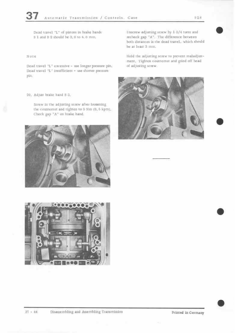
37 Automatic Transmission / Controls. Case 97.8
Dead rravel “L” of pistons in brake bands B 1 and B 2 should be 3.0 to 4. 0 mm.
Unscrew adjusring SCEW by 1 3/4 turns and recheck gap “A”. The difference berween both disrances is the dead travel. which should be ai least 3 mm.
Nore
Dead travel “L” excessive - use longer pressure pin. Dead travel “L” insufficient - use shorter pressure
Hold the adjusting screw to prevenr maladjust- men,. Tighten COUD~~~~UI and grind off head of adjusting screw.
v ‘-I-y J,.iy..~y*ea 20. Adjust brake band B 3.
Screw in rhe adjuring screw after loosening rhe counrernur and righren 10 5 Nm (0.5 kpm).
f i, / . . ,
Check gap “A” on brake band.
Y -TJp~~ “” Jjjmt 1 ,i k,*/, -!., 4
\ . . . I C.S. -
‘< \ I \ ..( K4w
--./ ? I
ly ? , ‘/_ ., $# , ,, \
*
31 - 44 Disassembling and Assembling Transmission Printed in Germany

!I28 Auromaric Transmission / Conrrols. Case 37
0 9 I i
i iL , --“, ” \ Q\
CT- L 2’ * \ 9 /
i? ggg (DWJ
Primed inGermany - III. 1879 Disassembling and Assembling Transmission Case 37 - 45

37 Automatic Transmission / Conrrols. Case 028
40. Description Nore When
WY. Special
Removing lnsralling lnsrrucrionr
1 Paw1 1
2 Spring 1
3 Pin 1
4 Circlip 1
5 R”1C 2 Tighten to specified rorquc
6 Washer 2
7 Anri-rertarr and 1 Adjust Page 37 - 15
backup light swirch
8 Bolt 1 Tighten to specified C”Iq”t!
9 Washer 1
LO Holder 1 Remove together with leaf spring and roller running on needle bearing
11 Leaf spring 1
12 Yeedle x
13 Roller 1
14 washer 1
15 Pin 1
16 Lockwasher 1
11 Linkage 1
18 Roller 1
19 Washer 1
31 - 46 Disassembling and Assembling Transmission Case Printed in Germany

928 Auromaric Transmission / Controls. Case 37
-
a
No. Descriprioli WY. Now When Special
Removing Installing lnstiuctions
20 screw 1 Tighten 10 specified 1orque
21 Washer 1
22 Shafr 1
23 Catch plate 1
24 S&31 1 Lever out with Drive in with suirable
suitable screw- 1001 driver
25 Plug 1 Tighien spe,cified LO 1orque
26 Seal 1 Replace
27 St21 1 Drive out with Drive in to correct suitable screw- position wirh suitable driver 1001; lip faces out
28 Snap ring 1
29 Cover 1
30 Seal 1 Replace, coat with ATF
31 Piston 1 Coar seal wirh ATF
32 Spring 1
33 Fast charging valve 1
for ie”erSe gear
34 Seal 1 Replace
35 sea.1 1 Replace, coat with ATF
36 Circlip 1
31 Washer 1
38 Lever 1
Primed in Germany - 111. ~7’3 Disassembling and Assembling I‘ransmission Case 37 47

37 Auromaric Transmission / Controls. Case 928
NO. Description Note When
Q~Y. Special
Removing Installing Instructions
39 Seal 1 Replace, coax with ATF and position COI- rectly
40 Spring retainer 1
41 Pressure unil 8 2 1 Do nor mix up wirh pressure unit B 1
42 Pressure unit B 1 1 Do nor mix up with
(identified by a groove pressure unit B 2
all around)
43 Seal 1 Replace, coat with ATF
44 Seal 1 Replace. coat with
ATF
45 Spring 1
46 Pin 1 Remove down- ward
47 Lever 1
48 Brake band guide 1
49 care 1
3: 48 Disassembling and Assembling Transmission Case Printed in Germany

928 Automatic Transmission / Conrrols. Case 37 DISASSEMBLING AND ASSEMBLING TRANSMlSSlON CASE
Disassembling
1. Unscrew holder and rcmwe with leaf spring and roller running on needles.
2. Remove lock for pressure units I3 I and B 2. and remove both ~resswe unirs.
1 - Pressure unir B 1 2 - Pressure unit 6 2
3. Pull our spring for bearing pin fror lever of brake band B 3 and drive OUI pin downward.
/-m -. w ,?pJ- 1
Assembling
1. Install catch plate in housing Guide shaft into spline of carch plate and tighren holding screw to specified rorque.
“IIIcyr: k e- -/~- / f. I. f-4
1 i/I. ‘y 1 ) ‘SF ““3 .; pi d i?
“\ i A. d
Primed in Germany - III. 1079 Disassembling and Assembling Transmission Case 37 - 03

37 Automatic Transmission / Controls. Case 928
2. Tnsrall linkage with washer and roller.
1 - Linkage 2 - Washer 3 - Roller 4 - Leaf spring 5 - Roller on needles
3. Install leaf spring and roller running on needles.
4. Install holder and tighten bolr to specified rorque.
5. Push spring on to bearing pin and attach in trans- mission case. Tension spring wirh a scribe or suitable wire hook and slide on the parking lock
37 - 50 Disassembling and Assembling Transmission Case Printed in Germany

-
928 Automatic Transmission / Controls. Case 37 6. Install pressure units B 1 and B 2 in ccnrecI
position and secure with lock. Note
A rubber insert is installed as from May 7. 1979 m eliminate hydraulic noise in the lubricating circuit. This rubber insert can be service insralled in rrans- mission without one.
I y- p” ‘^slb -1$’ ’ +@L _, /_I~ .,<- .Ji ‘t ’ ;‘;,\” ‘j
1 - Pressure unit B 1 2 - Pressure unir 6 2 A - Rubber inserr
Pressure unirs B 1 and B 2 have different designs and therefore musr not be mixed up. For idenri- ficarion B 1 pressure unit has a groove running all around.
Printed in Germany - 111. 1979 Disassembling and Assembling Transmission Case 37 - 51

928 Automatic TranrmisrionlControls, Case 37 a
INSTALLING AUTOMATICTRANSMISSION SECTION
If transmission (A) section is installed, the following parts must be transferred from the defective transmission to the new transmission.
1 - Front converter housing with mounting parts
2 -Torque converter 3 - ATF tank 4 - Bearing assembly with drive pinion and
mounting parts (replace O.ring) 5 - Final drive 6 - Adjusting nut
I I 3 6
hinted in Germany . VI, 1982 Installing Automatic Transmission Section 37-53

37 Automatic Transmission/Controls. Case 928
1. Take transmission section out of crate and remove protective caps.
\ :=--
/+;q -.*,,” .i’” ,R
y.+ 1 r~~;~fGj&g~ 1 ‘a\
i- ( ,d,yJ $-
Note:
The outer seal between the transmission case and final drive is missing on transmission section for manufacturing reasons.
2. Drive in outer seal to correct position with Special Tool 9180 (also refer to page 37 - 34).
Note:
The outer seal must be installed so that its sealing lip and spring supporting the sealing lip face the final drive.
Installing Automatic Transmission Section Printed in Germany

928 Automatic Transmission/Controls, Case 37
3. install torque converter and front converter housing (see page 32 1 I.
4. Redetermine thickness of shims for bearing assembly and install bearing assembly (see pages 39 24 and 39 - 29).
5. Adjust drive pinion and ring gear (ree page 39.311.
Printed in Germany - VI, 1982 Installing Automatic Transmission Section, 37 55

928 Automatic Transmission / Gears. Valve Body 38 a TOOLS
NO. Description Special Tool Remarks
1 Gauge ser us 1090
2 Gauge and coupling VW 1318 or P 318
3 Hose, adapters and bracket us 8030
hinted in Germany- 11, 1979 Checking Transmission Operarion 38- 1

38 Automatic Transmission / Gears. Valve Body 928
CHECKING TRANSMISSION OPERATION
Prior 10 making repairs on an automatic trans- mission. rrouhleshoor rransmission as insrrucied below and with help from rhr following tests.
A - General Checks
B - Transmission Fluid Level
C - Stall Test
D - Test Drive
E - Pressure Tesl
1mpurtant
All jobs, which require that engine runs, should only be carried out with selector lever in “N” or “P” and parking brake applied.
Exceptions: Tests, which require briefly a different selector lever position.
A - General Checks
Following jobs musr be performed prior to any resting of rransmission, and if defects are found. they must be eliminated before continuing with other work on transmission.
1. Check engine tuning (ignition timing, idle and tI.ansirion).
2. Check for external damage, e.g. leaks on transmission (ATF) or final drive (hypoid oil) and missing or loose mounting bolts.
B - Transmission Fluid Level
The specified fluid level is extremely importanr for proper operation of automatic transmission, so rbar following rest musk be canied out wirh great care.
Checking ATF Level
Also check appearance and odor of ATF. Buint friction linings cause a burnt odor. Contaminated oil could cause failure in valve body.
In this case transmission must be removed and repaired or replaced.
Test is carried out at engine idle speed, parking brake applied and selecror lever at “N“. Car must be on level surface.
Let engine run at idle speed 1 to 2 minutes before checking fluid level, so rhar torque conversed will be full.
ATF level can be checked o” a cold 01 warm transmission. However, the level will be more accurate on a cold rransmission (20’ - 30°C/ 66’ - 86’ F ATF temperature). An ATF temperarue of 80’ C/116’ F can only be guessrimated.
38 2 Checking Transmission Operation Printed in Germany

9 28 Automaric Transmission / Gears, Valve Body 38 ATF level in transmission will change wirh iluid remperarure. Max. and min. marks on rrannparenr tank are in reference to an ATF temperature of 80” C/116” F. When ATF temperarure is 20 I” 3@” C/68 - 86” F, the ATF level will be 30 mm/ 1 3/16 in. below minimum mark (see figure). The amount of ATF berween min. and max. marks is 0. 2 liters/C;. 1.5 fluid ounces.
, i. “‘TFj. ,,., >.. t -I
,”
I = max. at 80” C/116’ F ATF temperarure 2 = min. ar 80” C/116” F ATF remperature 3 = max. at 20 to 30’ C/68 - 86’ F ATF-
temperature
After correcting ATF level to specifications,
“perare brake pedal, leave selector lever in each posirion (R - N - D - N - R) several seconds and then return ir LO “N”. IO that working pistons of power pans are filled with ATF. Recheck and. if necessary. correct ATF level.
C - Stall Speed
This check provides informarion on operation of engine. converter and rransmission. It is applied. when rap speed cannot be reached or acceleration is insufficienr.
During this check all the engine power is convened into heat in the converter. which is why this check must nor last longer than 5 seconds.
Rear wheels mu%! not be permitted to turn for rhis check.
Also engine must be at operating remperarure and develop its full power.
Add ATF to correct level. Cleanliness is essential!
If ATF level is to” low, oil pump will draw in air, which can be heard. ATF will foam and cause incorrecr readings when checking ATF level. Stop engine unril ATF foam disappears (approx. 2 minutes). Add ATF and recheck ATF level.
Excessive ATF must be drained or drawn off. since orherwise traxmission componenrs would splash excessively and raise the remperarure to” much, until finally foamed oil is forced out through vent. This condition could damage transmission on a longterm basis.
Extra equipment. e. g. compressor for air condi- tioning, musk be turned off.
Check musr nor be made wirh car’s tachometer.
1. Connect tachometer thar ir can be read from driver’s sear.
2. Run engine at about 2000 rpm approx. 2 minutes prior to resring.
3. Apply parking brake all the way and depress brake pedal with left foot.
Printed inGermany - 11, 1979 Checking Transmission Operation 38 - 3

38 Auromaric Transmission / Gears, Valve Body 928
4. Position selector lever al “D”. floor acceleraror pedal wirh rigbr foor and check whether speci- fied srall speed is reached.
Stall speed must be 2400 + 200 rpm.
Note
If srall speed drops by approx. 400 to 700 rpm below specified value. one-way clutch in torque convener is slipping.
11~ srall speed is faster than specified value by about 300 rpm. slip is in transmission.
If srall speed is correcr alltl lop speed is still nor reached, one-way clurcl, is locking in both direc- Cons or has seized. This ‘xi!1 usually be noticed during fast highway driving by ATF leaking rhrougli the vent.
The srall speed will drop by app~ox. 125 rprn for each 1000 merers/3900 feer alrirude above sea level because of a drop in engine power.
Even excessively high outside lemperarures could cause stall speed to drop slightly below rhe mini- mum value.
38 - 4 Checking Transmission Operation Printed in Germany

AiltoniaIic ‘Tranjlliission / Gears, Valve Body 38 IL) Test Drlvr
Vehicle should be driven in all gear ranges and under all possible road condirioni. Do nor resr drlvc if lhere is obvious mechanical damage.
Shift poinrs in km/h (mph)
Seiecroi lever position “D”
Acceleraror pedal posilion
Llpsbiir
km/h (mph)
Par, 1hrott1e l-2-1 26 - 33 (16 - 21)
2-3-2 42 - 48 (26 - 30)
-
1. Kinte shift poilirr and compare 10 char above. Shifts should be smooth. Shifts should take place quickly and wirhout lag in power trans- mxsion.
2. Listen toi any sign of engine speedup between shifts. Speedup between shifts indicates slipping brake bands OI clutches.
3. After road WSI check transmission for fluid leaks.
All specified speeds are approximate
km/h (mph)
16 - 23 (10 - 14) 32 37 (20 - 23)
46 - 52 (28 - 32) 5: - 85 (35 - 53)
57 78 (36 48) 122 - 133 (76 - 83)
Printed inGermany II, 1979 Checking Transmission Operaion 38 - 5

38 Automatic Transmission / Gears, Valve Body 928
a E - Pressure Test
This tar will locate defects in ATF circuir (internal leakage, wear. sticking conrrol valves. dirt in ATF system).
a = main pressure b = governor pressure c = modulator pressure
69 PI i’ 1
.x.
:7
i
I A
..p i
‘I? c
Y -f 1, ”
ki’ -.
* I
Gauge and coupling from VW 1318 plus brackei and pars from US 8030.
Note
After removing gauges. install plugs with new seals.
Hose adapters for pressure gauges (from US 8030) Third gauge setup with US 1090
a
a 38 - 6 Checking Transmission Operarion Printed in Germany
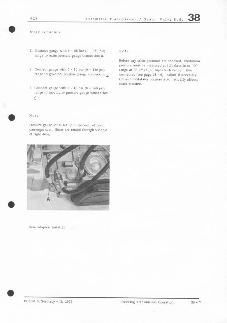
a
928 Auromatic Transmission / Gears. Valve Body 38 Work sequence
1. Connect gauge with 0 - 25 bar (0 - 350 psi)
range to main pressure gauge connection a.
2. Connect gauge with 0 - 10 bar (0 - 140 psi) range to governor pressure gauge connecrion 1.
Note
Before any other pressures are checked, modulator pressure must be measured at full throttle in “D” range ar 88 km/h (55 mph) with vacuum line connected (see page 38 - 9). Adjust if necessary. Correct modulator pressure automarically affects main pressure.
3. Connecr gauge with 0 - 10 bar (0 - 140 psi) range IO modulator pressure gauge connecrion c.
Note
Pressure gauge set is set up in footwell of front passenger seat. Hoses are routed through window of right door.
Hose adapters installed
a Printed in Germany - II, 1979 Checking Transmission Operation 38 - 1

38 Automatic Transmission / Gears, Valve Body !1 28
Checking Modulator Pressure
1. Compress circlip (arrow) and remove cover.
2. If inside of cover is wet with ATF. replace modulator.
3. Adjust if necessary.
Checking Main Pressure Note
Not adjustable. modularor pressure auromarically affects main pressure.
Changing modulator pressure also changes shifr points.
Checking Governor Pressure
Not adjustable.
Adjusting Modulator Pressure
1. Compress circlip and remove vacuum modulator cw/er.
2. Slightly pull adjuring key out and turn screw
3. After adjusring. push key into nearest slot. One turn of setting screw results in 0. 2 ba.1 (2.8 psi) pressure change.
Replacing Vacuum Modulator
1. Pull off vacuum hose.
2. Compress circlip and remove cover.
3. Remove modularor using 22 mm open end wrench.
4. When installing. apply non-hardening sealing compound to threads.
3R - 8 Checking Transmission Operation Printed in Germany

928 Auromatic Transmission/Gears. Valve Body 38
.o u g ; z .. E “= lo 22
CD
=’ g 3
ou3 d ,s
aI T 5 -5 & % c j z WY z 2 x e 2% ,; u SE .e Z” 95 z; 2 > y1 z :- e-2?
t
; g
1 N* n’ r‘
-
i-n 6 : j “0 0’ m_
F 2 r 2 &z ^NcoOdLc ?A&&iLA r-NcoO - - ---s cop-NY)(lrl d A N’ d ti 6 AuiAAAA d 2 c-i c-i n’ n’
qzi,^,^m^ ^NC)rn-Q”Lc S$&$$ . ..----- Coc-Ncom~ d 2 N’ N’ m’ d AuiAAAA d ?i c.i cd m‘ m‘
-I I
Printed inGermany IV. 1980 Checking Transmission Operation 38 - 9

928 Automatic Transmission / Gears, Valve Body 38
TROUBLESHOOTING AUTOMATIC TRANSMISSION
Note: If transmission oil is black and smells burnt or there is an unusual large amount of metal burrs in oil pan. either repair 01 replace transmission.
Conditions and Correctinn
Condition: Transmission slips in all selector lever positions
Correction: 1. Check modulating pressure, adjusting if necessary. If not adjustable, check movement of modulating pressure control valve. Clean modulating pressure safety valve in shift valve housing uppcr section.
2. Check whether vacuum line from intake branch to vacuum box is plugged. If yes, replace.
3. Check operating pressure. If too low or not available:
a) Disassemble and clan shift valve housing. and service operating pressure contrul valve.
b) Remove and inspect primary pump, replacing if necessary
Condition: Transmission grabs 01 car vibrates when moving off
Correction: 1. Check modulating pressure, adjusting if necessary.
2. Pull off vacuum line from vacuum box, checking whether ATF or fuel escapes.
a) lf ATF, replace vacuum box
b) If fuel, check fuel injection system and repair,
Primed in Germany - I, 1978 Troubleshooting 38 11

38 Automatic Transmission / Gears, Valve Body 928
Condition: 1st gear slips
Correction: 1. Check easy movement of cuntrul valve 8 1. replacing shift valve housing if necessary.
2. Remove and install brake band piston B 1. check seal and replace if necessary.
3. Replace brake band B 1 and pressure part for tl 1. Check easy movement of vent valves in support flange K 1. replacing support flange if necessary.
Condition: Transmission slips during Ist/Znd shift or in 2nd and 3rd gear
Correction: 1. Check modulating and operating pressures. adjusting if necessary.
2. Replace shift valve housing, also replacing sealing bushings on plug tubes.
3. Repair clutches K 1 and K 2 depending on findings. Visually inspect oil distribution sleeve, replacing if necessary.
Condition: Transmission slips in 3rd gear
Correction: 1. Remove shift valve housing, check sealing bushings on plug tubes and replace same if necessary.
2, Repair clutch K 2 depending on findings. Visually inspect oil distribution sleeve, replacing if necessary.
38 - 12 Troubleshooting Printed in Germany
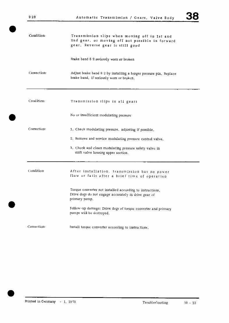
928 Automatic Transmission / Gears, Valve Body 38
Condition: Transmission slips when moving off in 1st and 2nd gear, OI moving off not possible in forward gear. Reverse gear is still good
Brake band 8 2 seriously worn or broken
Correction: Adjust brake band B 2 by installing a longer pressure pin. Replace brake band, if seriously worn or broken.
Condition: Transmission slips in all gears
Correction:
No or insufficient modulating pressure
1. Check modulating pressure. adjusting if possible.
2. Remove and service modulating pressure control valve.
3. Check and clean modulating pressure safety valve in shift valve housing upper section.
Condition: After installation, transmission has no power flow or fails after a brief time of operation
Torque converter not installed according to instructions. Drive dogs do not engage accuralcly in drive gear of primary pump.
Follow-up damage: Drive dogs oi torque converter and primary pumps will be destroyed.
Install torque converter according to instructions,
Printed inGermany - 1. 1978 Troubleshooting 38 13
38 Automatic Transmission / Gears, Valve Body 928
Condition: No power flow in all selector lever positions for a brief period immediately after starting engine (especially when car had not been used for a while)
Torque converter drains partially via leaky OI defective lubricating ring or valve in input shaft.
Correction: 1. Check lubricating ring on input shaft, replacing if necessary.
2. Checking ball valve in input shaft, replacing input shaft if necessary.
3. Check and clean lubricating pressure valve in shift valve housing.
Condition: No power flow in reverse gear
Correction: 1. Remove shift valve housing, check brake band B 3 and adjustment.
2. Remove brake band piston B 3 and check seal.
3. Replace one-way clutch in gear set.
Jondition: Strong jolt when engaging selector Lever in “D”
:orrection: 1. Adjust idle speed and CO level to specifications
2. Check modulating and operating pressures. correcting modulating pressure if necessary.
3. Check vacuum lint and connections for leaks.
Note:
4. Check whether pressure acceptance piston in rear transmission case moves easily and is installed correctly.
5. Check whether feed bore for pressure acceptance piston in rear transmission case is plugged.
If there is a hard engagement jolt when quickly shifting back and forth between “N” and “D” several times, there is no fault. The pressure pick-up requires a running time of approx. 2 seconds. If this time is given, the engagement jolt will also be correct.
38 - 14 Troubleshooting Printed in Germany

9 28 Automatic Transmission / Gears, Valve Rody 38
Condition: Strong jolts whtln changing gears
Correction: I. Check modulating and operating prcrrurcs. adjusting modulating pressure if n~crsaary. If operating pressure is too high, replace shift valve housing.
2. Check vacuum liilc and connections for leaks.
3. Scrvicc control valve for converter adaptation.
Condition Strong jolt in downshift from 3rd to 2nd gear
Correction: 1. Replace seal on release end of 8 2.
2. Replace brake band piston B 2.
Condition: No upshifts
Correction: 1. Check govemor pressure. If there is no govrrnur pressure reading, continue with point 1. If governor pressure is correct, continue with point 2.
2. Disassemble, clean and service centrifugal guvernor.
3. Disassemble and clean shift valve housing. replacing if necessary (use new sealing bushings on plug tuba).
Conditiun: No upshift on cold transmission. uprbifts okay nftcr short dirtancc
Correction: 1. Replace shift valve housing (use new sealing bushings on plug tubes).
Primed in Germany - I. 1978 Troublerhwting 38 15

38 Automatic Transmission / Gears, Valve Body 928
Condition: Upshifts only in upper speed range of gears
Correction: 1. Check and adjust control pressure cable.
2. Check governor pressure and replace centrifugal governor. if governor pressure is too low.
3. Service control prrssure valve.
Condition: Upshifts only in lower speed range of gears
Correction: 1. Tighten bolt for control pressure lever an transmission. Then check control pressure cable, adjusting if necessary.
2. Check full throttle stop. Move accelerator pedal to kickdown and check whether throttle is against full throttle stop, adjusting if necessary.
3. Check governor pressure and replace centrifugal governor. if governor pressure is too high.
Condition: No kickdown downshifts
Correction: 1. Check voltage at solenoid valve. If necessary. check wire connections against current flow diagram.
2. Remove solenoid valve. Connwt removed valve to power supply and check function. replacing if necessary.
3. Tighten control pressure lever bolt on transmission. Then check control pressure, adjusting if necessary.
4. Check movement of kickdown control valve in shift valve housing upper section, replacing shift valve housing if “CXeSSaIy.
38 - 16 Troubleshooting Printed in Germany

928 Automatic Transmission / Gears, Valve Body 38
Condition: Nu brake shifts from 3rd to 2nd and 2nd tu 1st
Correction: 1. Adjust control pressure cable,
2. Service brake shift piston, replacing shift valve tiousing if necessary.
Condition: Automatic, unwanted downshifts outside of partial throttle downshift range, without operation of kickdown switch
Correction:
l 1. Remove kickdown solenoid valve.
Check O-ring on solenoid valve for damage
2. Check whether kickdown switch sticks in pressed position, re- placing if necessary.
3. Check whether solenoid valve sticks in open position. re- placing solenoid valve if necessary.
4. Check movement of control pressure valve, cleaning shift valve housing and servicing valve if necessary, or re- placing shift valve housing.
Condition: Poor acceleration when moving off
Correction: 1. Check stall speed.
2. If stall speed drops below specified value by approx. 400 to ‘700 rpm. one-way clutch in converter is slipping. i?e- place torque collverter.
Condition: Transmission does not make upshifts
Correction: 1. Check governor pressure and when not correct, clean and service centrifugal governor. If correct. continue with point 2.
2. Service master valve in shift valve housing. replacing shift valve housing if necessary.
Printed inGermany I. 1978 Troubleshooting 38 17
38 Automatic Transmission / Gears, Valve nody 928
Condition: Parking lock does not engage
Correction: Check adjustment of selector lever cable. correcting if necessary.
Condition: Selector lever cannot be engaged in “H” and *P
a) With engine running b) With engine stopped
Correction: 1. a) Disassemble, clean and service centrifugal governor.
2. b) Service blocking piston in rear transmission case.
Condition: Engine cannot be started with selector lever in “P” or “N”
Correction: 1. Adjust selector lever cable and starter interlock switch.
2. Replace starter interlock and backup light switch.
Condition: Invisible oil loss (leak cannot be seen on outside)
Diaphragm in vacuum box defective. ATF drawn in by engine via vacuum line.
Correction: Replace vacuum box
Condition: Sudden thick smoke caused by defective vacuum box
Correction: Replace vacuum box
38 _ 18 Troubleshooting Printed in Germany

928 Automatic Transmission / Gear, Valve Body 38
Condition ATF lost between torque converter and primary
pump
Correction: 1. Install and tighten drain plug for torque converter, using a new seal. Coat threads with Hyiorna. If still leaking ATF, continue with points 2 and 3.
2. Replace radial seal and O-ring of primary pump. checking O-ring groove in primary pump for porous spots. Heplace primary pump, ifs nccrssary.
3. Apply a good coat of iiyloma tn threads of hottom mounting bolts.
Condition: Oil leak behind starter interlock and backup light switch
Coircction: Replace O-ring on pressure part li 2.
Condition: 2nd gear loud
Correction: Replace rear planet gear set.
Condition Whining noise only when changing gears with full load
C:orrrction: Replace: oil filter
c:undition Whining noise. which increases in loudness as engine spvcd rises
Correction: Check primary pump. replacing if necessary
Printed in Germany I, 197~ Troubleshooting (8 19

Y?i‘ Automatic Transmission / Gears. Valve Body 38
REMOVING AND INSTALLING SllIFT VALVE IHOUS,N(;
RL moving
I. hlilve selector lever to “P”.
2. Llnrrrew nil rill+3 tube lronl oil pan and let ATF drain.
.
? ,:: *
A., ‘; ‘.
_
’ /
2. llnscrcw oil filler tube coupling and turn out filler tube.
i
4. L’nscrew oil pan mounting bolts and remove
oil pan with gasket.
Note: Ii ATF smells burnt and there is metal abrasion
in oil pan. sludge or an unusual large amount of burrs. it is not sufficient to only replare shift valve housing. The entire transmission and torque converter will have to be replaced. Further oil lines and oil cooler will have to bc flushed clean thoroughly.
5. Remove oil filter
1 Mounting bolts 2 - spacer
3 Oil filter
Primed in Germany I, 1gq Removing and Installing Shift Valve Ilousing
18 - 21

38 Automatic Transmission / Gears, Valve Body 928
6. Unscrew mounting bolts of shift valve housing
and remove shift valve housing. 2. Install locating pin (suitable punch) for control
pressure valve in shift valve housing.
7. Remove plug tubes with sealing bushings and
pull off sealing husbings from plug tubes. 3. Guide in shift valve housing carefully. Make SUE in particular that range valve engages
correctly in catch plate.
Installing
1. Fit new sealing bushings on both ends of plug tuber and install tubes in transmission. Screw two locally made centering pint in trans- mission case.
4. Install mounting bolts with spring washers and tighten to specified torque.
A Centering pins
38 - 22 Removing and Installing Shift Valve Housing
Printed in Germany

928 Automatic Transmission / Gears. Valve Body 38
5. Remove locating pin for control pressure valve.
6. Install oil filter.
7. Install oil pan with gasket and tighten mounting bolts to specified torque.
8. Screw oil filler tube on oil pan and tighten coupling nut.
9. Add ATF as specified
As from May I. 1979 a rubber insen is insraIled IO eliminate hydraulic noise in rhe lubricating circuir. Rubber inserra can be service installed in a trans- mission without one.
M j ;;i:: ~: m
,: ,
a , I?
_ .* ~-a CY h ‘.{“i
*-$ i .\-2’: , - *
)pji--- .- ~~*_ -
,. =
--rJf?$<p:qTG$;
IO. Check shifts during test drive.
11. Check ATF level while warm. A - Rubber insert
12. Tighten bolts on oil pan to specified torque.
l Printed in Germany - III, 1979 Removing and Installing Shift Valve
1 lousing
3R - 23

38 Automatic Transmission / Gears, Valve Rodv 928
MODIFICATIONS ON SHIFT VALVE HOL’SING
The shift valve housing has an additional plastic brake band holder from rransmission numbers
16:) 0626 A 22.01 Europe. Resr of World and 169 3254 A 22.02 USA, Japan.
The cast brake band holders have been omirred on these housings.
y
-* .$!.
* ,, .s s i
-:., _ , , US
j -y. -I.-‘<. -’
. . I .!’
1 - Old version with cast brake band holders (arrow)
2 - New version (install only with plastic brake band holder)
a
Only the new version will be available afrer de- pletion of old version shift valve housing stocks. Old and new version shift valve housings are inrer- changeable. however rhe new version (without casr brake band holders) will always require in- stallation of rhe plastic brake band holders.
38 - 24 Removing and Insralling Shift Valve Housing I”, l!JKo -Printed in Germany

928 Automatic Transmission/Gears, Valve Body 38 a
TOOLS
a : ‘1 .,i ;i 9 .:I ‘$ .I
d ri .A
,# I ; i
NO. Description Special Tool Remarks
Filler Standard, e.g. Dresser-Wayne Model 3009
hinted in Germany -VI, 1982 Replacing ATF and Filter 38 - 25

38 Automatic Transmission/Gears, Valve Body 928
REPLACING ATF AND FILTER
ATF Capacity:
Initial filling: approx. 6.0 liters/6.3 US.qt ATF change: approx. 5.5 liters/5.7 US.qt
Type of ATF:
ATF Derron @ or Dexron II @
ATF and filter must be replaced every 48,000 km/30,000 miles.
Note:
ATF (not filter) should be replaced more often. if car is subjected to severe operating conditions (trailer hauling etc.).
Car must be on level surface when replacing ATF. Also have transmission at operating temperature and engine stopped.
Unscrew oil filler tube from oil pan and let ATF drain.
Unscrew filler tube coupling nut and turn out filler tube.
Turn crankshaft until converter drain plug can be seen and removed.
Remove transmission oil pan and replace oil filter when ATF stops draining from transmission and torque converter.
38.26 Replacing ATF and Filter VI, 1982 hinted in Germally
a
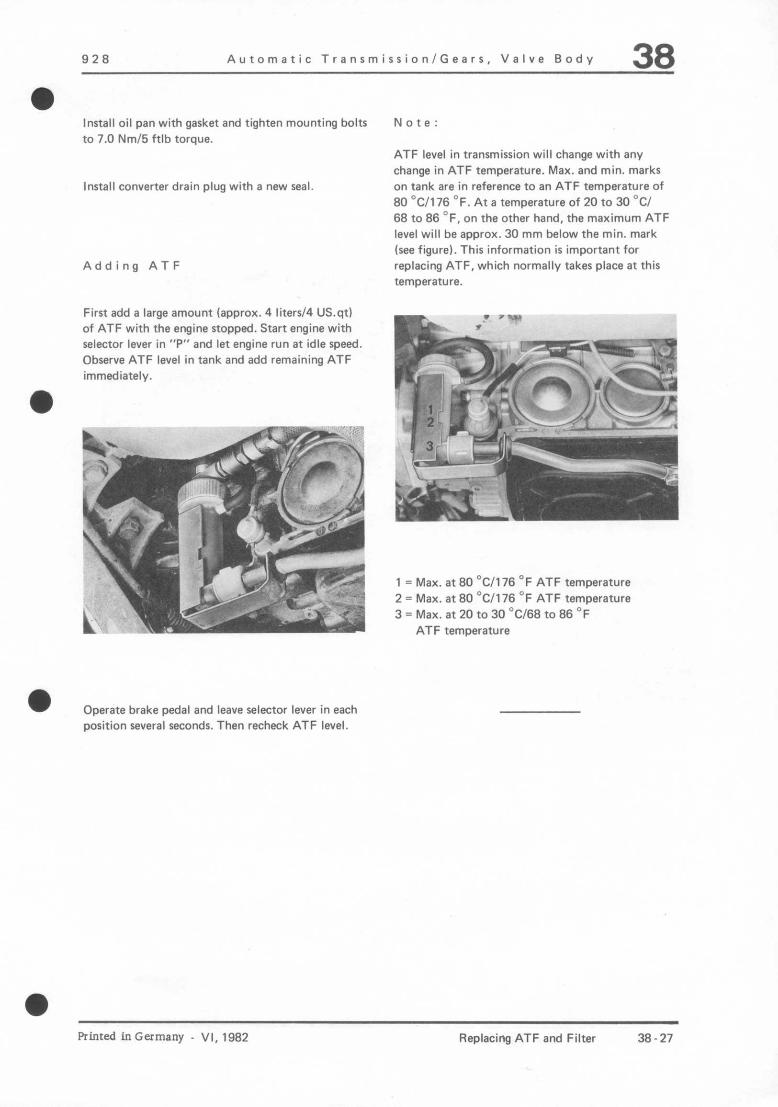
Automatic Transmission/Gears, Valve Body 38
Install oil pan with gasket and tighten mounting bolts to 7.0 Nm/5 ftlb torque.
Install converter drain plug with a new seal.
Adding ATF
First add a large amount lapprox. 4 liters/4 US.qt) of ATF with the engine stopped. Start engine with selector lever in “P” and let engine run at idle speed. Observe ATF level in tank and add remaining ATF immediately.
Operate brake pedal and leave selector lever in each position several seconds. Then recheck ATF level.
Note:
ATF level in transmission will change with any change in ATF temperature. Max. and min. marks on tank are in reference to an ATF temperature of 80 “Cl1 76 OF. At a temperature of 20 to 30 “Cl 68 to 86 OF, on the other hand, the maximum ATF level will be approx. 30 mm below the min. mark (see figurel. This information is important for replacing ATF, which normally takes place at this twnDerat”re.
1 = Max. at 80 ‘Cl176 =‘F ATF temperature 2 = Max. at 80 “Cl176 OF ATF temperature 3 = Max. at 20 to 30 “C/68 to 86 “F
ATF terrmerature
Printed inGermany - VI, 1982 Replacing ATF and Filter 38-27

38 Automatic Transmission/Gears and Valve Body 928
FLUSHING ATF COOLER AND LINES
Note 2. Attach extra hose from ATF charger (see Work- shop Equipment Group of Special Tool Catalog)
If ATF smells burnt and there are metal particles or sludge in oil pan, it is not sufficient to only replace the valve body or transmission. The ATF cooler and lines will also have to be flushed with ATF.
on return line and flush cooler as well as lines with the charger.
1. Detach feed and return lines at converter housing and take off short hose from return line.
A -To cooler inlet (bottom connection) B - From cooler outlet (top connection)
38.28 Flushing ATF Cooler and Lines Printed in Germany

928 Auromaric Transmission / Gears. Valve Body 38
16
17 kz’ (---Jr’8
115 I.1
9 MT2 P B 8
~~~$q-l”o
‘1
~*&)f ‘I It Bm
6
Printed in Germany - 111. 1979 Disassembling and Assembling Centrifugal Governor 38 - 29
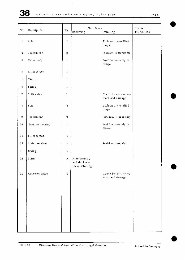
38 Auromatic Transmission / Gears, Valve Body 928
JO. Descriprion Now When
WY. Special
Removing Installing lnsrrucrions
1 HOlK 2 Tighren to specified torque
2 Lockwasher 2 Replace. if necessary
3 Valve body 1 Posirion correctly on flange
4 Filler ScIern 1
5 Circlip 1
6 Spring 1
7 Shift valve 1 Check for easy move- ment and damage
8 no1r 2 Tighten to specified COrq”t?
9 Luckwasher 2 Replace, if necessary
LO Governor housing 1 Position correcrly on
flange
11 Filter screen 1
L2 Spring rerainer 1 Position correctly
13 Spring 1
14 Shim X Nore quanriry and thickness for reinstalling
15 Governor valve 1 Check fur easy move- menr and damage
38 30 Disassembling and Assembling Centrifugal Governor Printed in Germany
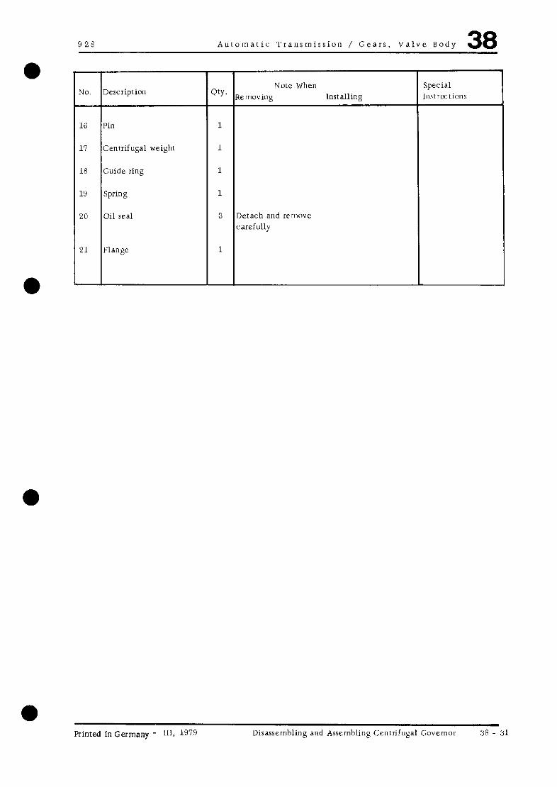
Autoroaric Transmission / Gears, Valve Body 38
a Printed in Germany - III. 1Wg Dirassernbling and Assernhlirig Centrifugal Governor 38 31

38 Auromaric Transmission / Gears. Valve Bodv 92x
DISASSEMBLING AND ASSEMBLING CENTRIFUGAL GOVERNOR
Disassembling
1. Unscrew bolts and remove valve body as well as governor housing from flange.
h- ,jzqq ;~
?:’ ’ 7 ‘1 “~y2 ~
..-~ rn~ _’ f -\
Be careful noi 10 damage filter screen in flange when taking off housing.
2. Press off spring retainer. Remove cenrrifugal weight with valve and springs.
I
Assembling
Clean all pars in clean gasoline thoroughly. Check shift valve and governor valve for damage and easy movement in their bores.
1. Place filler screen in seat provided for this pur- pose in oil bore and install valve body on flange [hat oil outler slot faces oil seals and oil bores align.
A
ri 63 -a
\
q$,,-., 1 L
.* *i
\I ,=!2 Q, fi,
\$’ \,’ .’
s-f
-1
A
A - Gil bores
2. Place filler screen in seat provided for this pur- pose in oil bore and install governor housing rhar oil outlet slot faces oil seals and oil bores al@;.
A - Oil bores
38 - 32 Disassembling and Assembling Centrifugal Governor Printed in Germany

928 Automatic Transmission / Gears. Valve Body 38 0 TOOLS
NO. Description
1 Assembly tool
Special Tool
9307 I Remarks
Printed in Germany - III. 1979 Disassembling and Assembling Gear Assembly 38 - 33

38 Automatic Transmission/Gears, Valve Body 928
r-.-.--7
I \
p&g. \ 14
1% zq >c 2 c1 \- \
cl . . . 4
\ L \ ,3&IQ$&g ‘i
,* L---- i
11 -"
10 \
g p&j m \
a 24
25 . . : *"‘.,
,,~\\-j .? 28 tic-.
,I ill , 0 '- 27 c-,"ip 28
7 r/f,
!g! \\i
21-f
"'-I&*p
46
-'; m' #Ill.
(g‘p % 9
77 ,
1 *\ 1 :
I\ i;)
:!I
2dL1;
3'
j ilk- 22
il.
#!p$yj \%_ ,
1 'ii, 23 21
20
,,f ‘T’,( .nlTm 18
38-34 Disassembling and Assembling Gear Assembly VI,1982 - Printed in Germany

928 Automatic Transmission / Gears, Valve Body 38
Note When IO. Description Qty.
Special Removing Installing Instructions
1 Input shaft 1
2 Shim X Note quantity Redetermine thickness, and thickness if necessary for reinstalling
l
l
a
l -
3 Lubricating pressure ring 1
4 Radial bearing 1
5 Planer carrier gear 1
6 Axial bearing 1
I Shim x Note quanrity Redetermine thickness, and thickness if necessary
for reinsralling
8 Axial bearing 1
9 sun gear 1
0 Radial bearing 1
1 Circlip 1
2 Shim X Note quantity Redetermine rhickness. and thickness if necessary for reinstalling
,3 Clutch K 1 1
.4 Oil distribution sleeve 1 Position correcrly
.5 Clutch K 2 1
,6 Hollow shaft 1
.7 Radial bearing 1
.8 Radial bearing 1
.9 Thrust washer 1
10 Intermediate shaft 1
hinted inGermany - III. 1g7g Disassembling and Assembling Gear Assembly 38 - 35

38 Automatic Transmission/Gears, Valve Body 928
Note When uo. Description Qty.
especial Removing Installing Instructions
!l Radial bearing 1
!2 Output shaft 1
!3 Thrust washer 1 An aramide plastic washer without turning lock is installed instead of metal thrust washer betw. rear pla- net set and in- termediate shaft for transm type A 22.04 as well as for type 22.01 from 1981 models
!4 Ball bearing 1
!5 Thrust washer 1
!6 Sun gear 1
!7 Split needle bearing 1
!8 Axial bearing 1
38-36 Disassembling and Assembling Gear Assembly VI, 1982 Printed in Germany

92R Automatic Transmission / Gears, Valve Body 38
a DISASSEMBLING AND ASSEMBLING GEAR ASSEMBLY
Disassembling Assembling
1. Slide Special Tool 9301 on LO the ourput shaft and position rhe entire gear assembly upright carefully.
a
1. Lubricate and install axial bearing and split needle bearing.
illi
I I;
-;--i h F
-- . . .
-- _(_ - ‘II . . .
b$
i -9s
fi!#,la;$Ty
:,! ( ~, ::,’ ;, ., ,” f -) ;
‘I I-,, ‘;) ji
‘++xiihm- ” -r”/
c .,.
2. Inrrall sun gear and rhrw washer.
Coared side oi thrust washer faces sun gear.
3. Heat ball bearing to about 120’ C and press on with a suitable piece of pipe.
4. lnsrall hollow shaft in one-way clutch that shaft
l 2. Remove snap ring and rake off clutch K 1 and turns in direcrion of arrow shims.
a Printed in Germany - III, 1979 Disassembling and Assembling Gear Assembly 38 - 37
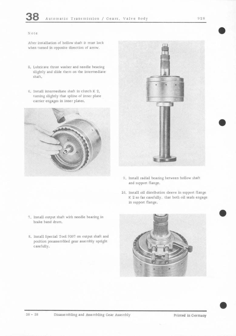
38 Automatic Transmission / Gears. Valve Body !JZR
After installation of hollow shaft it must lock when turned in opposite direction of arrow.
5. Lubricate rhrusi washer and needle bearing slightly and slide them on rhe inrermediare shaft.
6. lnsrall intermediate shaft in clutch K 2, turning slightly that spline of inner plate carrier engages in inner plates.
i i, =a-- -* w
w ,. s. -7
9. install radial bearing berween hollow shaft
and supporr flange.
10. Insrall oil distribution sleeve in support flange K 2 so far carefully. rhar borh oil seals engage in support flange.
7. Insrall output shaft with needle bearing in brake band drum.
8. Install Special Tool 9307 on output shaft and posirion preassembled gear assembly upright carefully.
yrm
38 - 38 Disassembling and Assembling Gear Assembly Printed in Germany

Y28 Automatic Transmission / Gears. Valve Body 38
0 11. Install clurch K 1 carefully. making sure rhat oil seals engage properly.
1-T c P’
/xc i.>
12. Check axial play of hollow shafr. ---
Install circlip wilhout shims and check play with a feeler gauge
&S&k&$& ~&++ ;iF “kq\.; ,- p*.
a ‘\“, . \- “’ i: -- P I. ,.~ y //-
Measure distance “b” from face of inner plate carrier to shoulder of planet gear carrier.
WT. ,.fl
, ,’
f/^
--%\
&fF i 1 a?’
:, ‘.I
+?y
.‘\ j
1, ‘* -.. - ::~
_- *’ f
Insrall shims to adjust play IO specified value of 0.3 IO 0.4 mm.
13. Check axial play of sun gear. Measure distance “d” from face of intermediare shaft IO shoulder of inrermediare shaft.
Lubricate and install axial bearing in planer gear Carrlel.
Measure distance “a” fmm face of inner plate carrier to roller of axial bearing with a deprh gauge.
a Printed inGermany - III. 1019 Disassembling and Assembling Gear Assembly 38 - 3’)

38 Automatic Transmission / Gears. Valve Body 928
Install sun gear and needle bearing.
Measure disrance “e” from face of intermediate shaft IO face of sun gear.
Calculate play: Dis[ance “a” _ “b” = I’c,’ Disran,-e “d” _ ,‘e” = “f”
Distance “c” - “f” = play
Adjust play 10 specified value of 0. 2 IO 0. 3 mm by installing shims underneath rhe axial bearing.
14. Install planer gear carrier, turning ir back and forth IO have inner plate carrier engage in spline of plates.
15. lnsrall radial bearing and input shafr
16. lnsrall and attach Iuhricating pressure ring in groove of input shafr.
a 38 - 40 Disassembling and Assembling Gear Assembly Printed in Germany

Auromaric Transmission / Gears. Valve Body 38
TOOLS
-
N@.
1
2
-
Description
Assembly sleeve
Assembly tool
;pecial Tool Remarks I
9308
9309
Printed inGermany - III, 1979 Disassembling and Assembling Clutch K 1 38 - 41

38 Automatic Transmission / Gears. Valve Body Ii 2 8
a
0
\T---
c-
0)
+LA.LA
fF
,@a**e, ” p
“a”
: 7. ,\%,
-.~L kp” .-,_mC.. h
a
a
a 38 - 42 Disassembling and Assembling Clutch K 1 Printed in Germany

-
a
928 AurorriaLic Transmission / Gears, Valve Body 38
UO. uescrlprlon
a Printed inGermany - III, 199 Disassembling and Assembling Clutch K 1 38 - 43
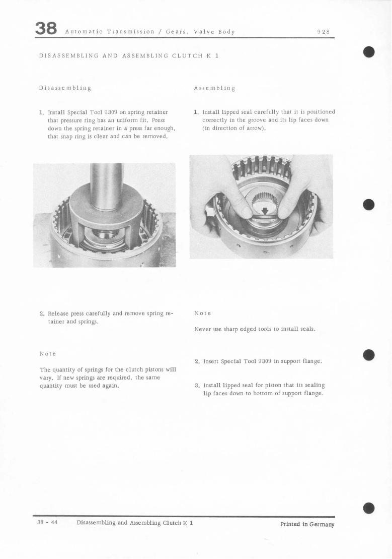
38 Automatic Transmission / Gears. Valve Body 0 28
DISASSEMBLING AND ASSEMBLING CLUTCH K 1
Disassembling Assembling
1. Install Special Tool 9309 on spring retainer rhar pressure ring has an uniform fit. Press down rhe spring retainer in a press far enough, that snap ring is clear and can be removed.
1. Install lipped seal carefully that ir is positioned correctly in the groove and its lip faces down (in direction of arrow).
2. Release press carefully and remove spring re- rainer and springs.
Note
Never use sharp edged rools [a install seals.
Note
The quantity of springs for the clutch pistons will vary. If new springs are required. rhe same quantity must be used again.
2. loser1 Special Tool 9309 in support flange.
3, Install lipped seal for piston that its sealing lip faces down to borrom of support flange.
a 38 - 44 Disassembling and Assembling Clutch K 1 Printed in Germany
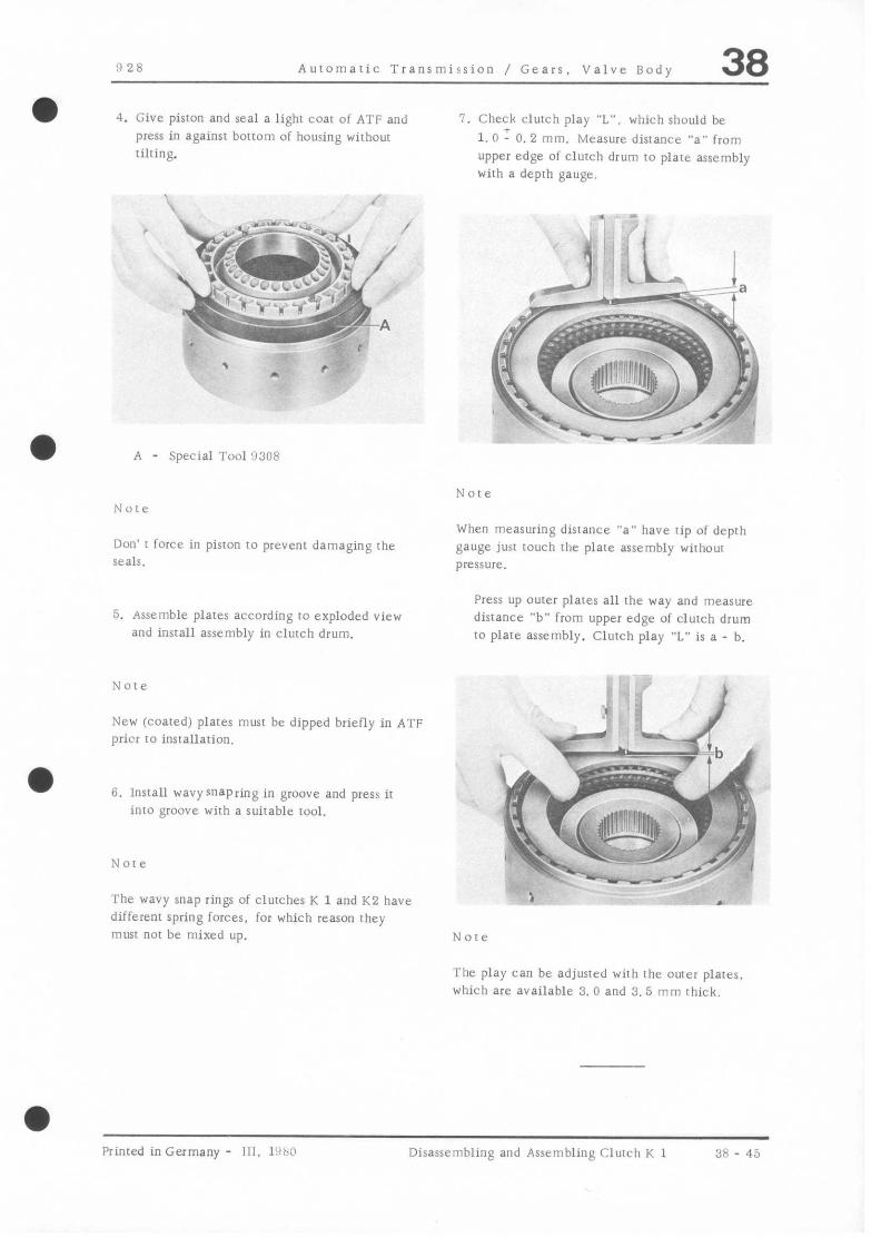
!I 28 Automalic Transmission ,I Gears. Valve Body 38
4. Give pisron and seal a lighr coat of ATF and press in againsr bottom of housing without tilting.
1. Check clutch play “L”. which should be
1. 0 T 0. 2 mm. Measure distance “a” from upper edge of clutch drum to plate assembly wilh a deprh gauge.
A - Special Tool !I308
Note Note
Don’ I force in piston to prevent damaging rhe Seals.
When measuring distance “a” have tip of depth gauge just touch rhe plate assembly wirhou! pressure.
5. Assemble plates according co exploded view and install assembly in clutch drum.
Press up outer plares all rhe way and measure disrance “b” from upper edge of clulch drum to plate assembly. Clutch play “L” is a - b.
New (coaled) plares must be dipped briefly in ATF prier I0 insrallation.
8. lnsrall wavysnapring in groove and press if into groove wirh a suitable tool.
The wavy snap rings of clutches K 1 and K2 have ; .
different spring forces. for which reason rhey must not be mixed up. Note
The play can be adjusred wirh rhe ouler plater, which are available 3. 0 and 3. 5 mm thick.
Primed in Germany - 111. 1’1~13 Disassembling and Assembling Church K 1 38 - 45

‘1 2;; Automatic Transmission / Gears. Valve Body 38
e-@- $!
-!.! z >’ if2 5 ‘. \
fg$p- (0
,$$.$ ~~ ~;;.~\~~;, ‘j)’ ,‘lT\
-.r*
L3v* r-c / ?/A
$!
p,/=>,
0
j---T--
” ;.&
‘+0-$
c v/&+-- g
qz.q ul ygj$ *
. -” --I 4qjsJL;
tfgg$--- CJ--
Printed in Germany - 111. 1970 Disassembling and Assembling Clutch K 2 38 - 41
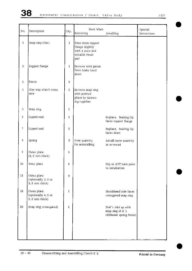
38 Automatic 1‘ransmissi”n / Gears. Valve Body !I 28
9”. Descriprion CRY. Note When Special
Removing lilsralling Insrrucrions
1 Snap ring fflat) 1 Press down support flange slightly with a press arid suirable thrust
w’
2 Support flange 1 Rcn~vve with piston from brake band drum
3 Pisron 1
1 One-way clutch outer 1 Remove snap ring race wirb poimed
pliers by squeez- ing rogether
5 Snap ring 1
6 Lipped seal 1 Replace. Sealing lip faces supporr flange
7 Lipped seal 1 Replace. Sealing lip faces down
8 Spring X Note quantity Install same quanriry for reinsralling as removed
9 ourer plate 1
(2. 0 mm thick)
10 inner plate 6 Dip in ATF baih prior 10 insrallation
11 outer plate 4
(optionally 3. 0 01 3. 5 mm thick)
12 outer p1are 1 Shuuldered side faces (oprionally 4. 5 or corrugared snap ring
5. 0 mm thick)
13 Snap ring (corrugated) 1 Don’ I mix up with snap ring of K 1 (different spring force)
38 - 48 Disassembling and Assembling Clutch K 2 Printed in Germany

928 Auromatic Transmission / Gears. Valve Body 38
No. Description Q’y. Uote When Special
Removing Installing lnsiructions
14 oute1 plate 1 Shouldered side faces (5. 0 mm thick) corrugated snap ring
15 Guide ring 1
16 Brake band drum 1
DISASSEMBLING AND ASSEMBLING CLIITCH K 2
a Disassembling 3. Remove all springs and plares from rhe brake band drum.
1. Remove flar snap ring wirh a suirable tool. while pressing the supporr flange down slightly in a Note press wirb a suitable thrust pad (e.g. VW 511).
The quantity of springs for clutch pistons will vary. If new springs are required, rhe same quantity as removed must be installed.
4. Remove corrugated snap ring and outer plate as well as guide ring for springs.
6. Squeeze snap ring together with a pointed pliers and remove one-way clutch oura race.
2. Take support flange and piston out of brake band drum.
Note
Supporr flange and piston must be held together IO prevent the piston from falling OIX.
Printed in Germany - III, 19’i9 Disassembling and Assembling Clutch K 2 38 - 49
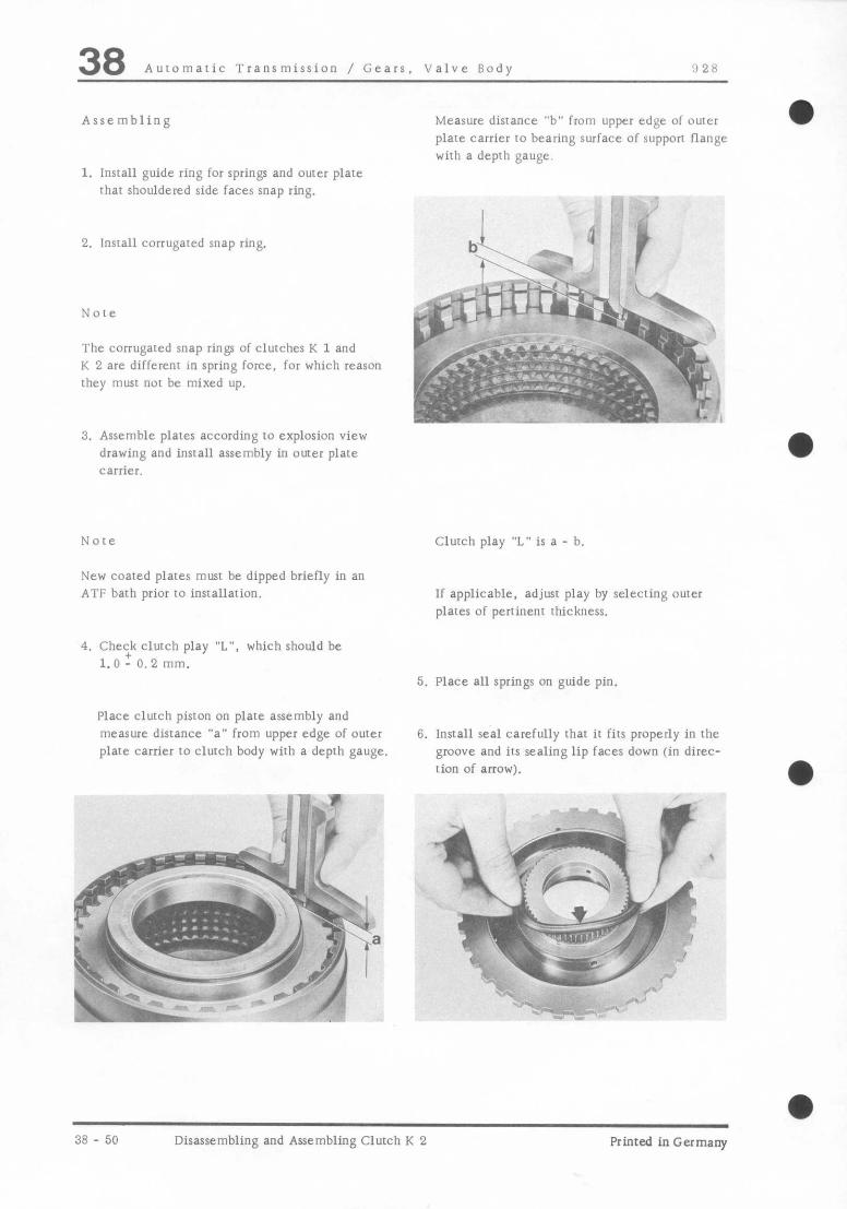
38 Auromatic Transmission / Gears. Valve Body !I 28
Assembling
1. Install guide ring for springs and outer plate rhar shouldered side faces snap ring.
2. lnsrall corrugated snap ring.
Note
The corrugated snap rings of clutches K 1 and K 2 are different in spring force, for which reason they must not be mixed up.
3. Assemble plares according to explosion view drawing and install assembly in outer plare carrier.
New coated plares must be dipped briefly in an ATF bath prior to installation.
Measure distance “b” from upper edge of outer 0
plare carrier to bearing surface of support Lange with a depth gauge.
Clurch play ‘7” is a - b
If applicable, adjust play by selecting ouwr plates of pertinent thickness.
4. Che:k clurch play “L”. which should be l.O-0.2mm.
5. Place all springs on guide pin.
Place clutch piston on plate assembly and measure distance “a” from upper edge of ouer plate carrier 10 clurch body wirh a deprh gauge.
6. Install seal carefully that it fits properly in the groove and its sealing lip faces down (in direc- rion of arrow).
,
3.8 - 50 Disassembling and Assembling Clutch K 2 Printed in Germany

928 Auromatic Transmission / Gears. Valve Body 38
Never use sharp edged rools to install seals.
7. Install seal for piston so that its sealing lip faces down.
6. Apply a light coat of ATF IO seals and insrall piston in support flange, pressing rhe sealing lip into [he supporr flange with a pencil OI ball point pen and moving in the piston care- fully withour Ming.
9. lnsrall snap ring in groove of supporr flange, squeeze rogether with a needle-nose pliers and insert one-way clutch outer race.
hinted inGermany - 111. 1980 Disassembling and Assembling Clutch K 2 3x - 51

!I 28 Differential/Tr.lnsaxle Syrtcm --.
NO. Description
1 Mandred US SOSO/lO
2 Pin
Sprcial Tool
Printed in Germany Removing and Installing Differential 39 - 1

39 Dlfferential/Transaxle System 928
(I) 77 e”! $yBq!?.. “;”
l#yF9 ~
~<.~,i;yqg$t+ ~ ! \ _ % +, _ “>,
6 --f
j ?2z?g N
P
-
a 39 - 2 Removiq and Installing Differential Printed in Germany

928 ~iffcrential/Transaxle System 39 -
No
-
1
2
:A
4
5
u
7
8
9
10
11
12
13
14
1s
16
-
Description
Nut
iz’asher
Holder
Rear cove1
Gasket
ROB
Axle flange
fiolt
Washer
Side cover
Shim
O-Ring
ail seal
Tapered roller bearing outer race
Differential
cast
-
ZY. -
12
12
1
1
1
2
2
12
12
2
x
2
2
2
1
1
-
Removing
Note When Special
Installing Instructions
Mark for Must be installed on reassembly same side
Note number and
thickness for reassembly on each side
Determine again. if necessary
Prrss out with suitable screw- driver
Mark for reassembly
Tighten to specified
torque
Replace if necessary
Replace
Tighten to specified torque
Tighten to specified torque
Replace if necessary
Replace. coat slightly with trans- mission oil
Drive in with us 8050/10
Install in same side cover, heat side COVeI to appion 100° C/212O F and drive in with a suitable mandrel
Adjust, il necessary
Printed in Germany Remwing and Installing Diffcrcntial 39 - n

39 Differential/Transaxle System 928
REMOVING AND lNSTAI.l.lNG DIFFERENTIAL 0
Removing
1. Drain transmission oil. Note
2. Unrcrciv axle Ilange bolt and remove axle flaqx.
Prcload of the tapered roller bearings could cause
tension on the case when tightening bolts for the side covers, which later could impair installation of the rear cover. consequently the rear cover should be installed before tightening the bolts.
Installing
Drive in axle flan&e real with US 8050/10.
79 - 4 Removing and Installing Differential Printed in Germany

928 Differential/Transaxle System 39 a
TOOLS
0
! No. Description Special Tool Remarks
1 Mandrel P 263
2 Extractor US 1018
3 Drift P 264 b
Primed in Germany Disassembling and Assembling Differential 39 - 5

39 Dlfierential/Transanle System 928
.Y “‘f-
p--’ ‘: 17 eu t-
f-l <J
m am-.
‘I
~
..,=-;F
*, I’ \ i.-id \ i \\\
co \ fJ c ._s \
‘L ‘,, c \, a.9 \ \ - . . .~ \ ,,
0 ‘- ‘L-
‘y. /,’ r ?’ ~, -1
39 - 6 Disassembling and Assembling Differential Printed in Germany

928 Diffeiential/TranraxIc System 39
NO. Description Qty. x”le When Special
Removing Installing Instructions
1 Tapered ruller bearing 2 Pull off with Drive on with inner race US 1078 and P 264 b
P 263
2 Circlip 1
3 Magnet carrier plate 1
4 Luckplate 6 Replace
5 Bolt 1‘2 Threads must be dry and greaseless. Tighten to specified torque
6 Ring gear 1 Heat to approx. 100’ C/212’ F. Tapped holes for ring gear bolts must be dry and greaseless. Note pair number. Adjust if necessary
I Roll pin 1
8 Differential gear shaft 1
9 Small differential gear 2 Coat thrust surface with MoS2 paste. Replace only in pairs
10 Large differential gear 2 Coat thrust surface with MoS2 paste. Replace only in PtlirS
11 Axle flange nut 2
12 Split pin 1
13 Differential housing 1
Printed in Germany Disassembling and Assembling Differential 39 7

39 Differential/Transanle System 928
DISASSEMBLING AND ASSEMBLING DIFFERENTIAL a
Disassembling
1. Pull off tapered roller bearing inner race with an extractor US 1078 and Special Tool P 263.
2. Drive ring gear from housing with a suitable mandrel.
,- ,’
6” - I.... !
/- ‘ ---v --+ l C
Claws of both legs might have to be machined.
-. ,l id c ,’ ).‘>.- _ . -,*: ,
, ,
yrc -SC m-n- -.
1
Assembling
1. Heat ring gear to approx. 100” C/212” F and install. Use local manufactured centering pins as guides.
A - Centering pins (local manufacture)
2. Tighten ring gear bolts to specified torque. Slide lockplate into bolt head groove. Squeeze lockplate ends together with pliers. Bend lock- plate ends down over side of bolt head.
39 - 8 Disassembling and Assembling Differential Printed in Germany

‘1 2 4 Differential/Transaxle System 39 3. Coat oval surface of differential gears with
hlOSz paste.
4. Install large differential gears with press-fit
threaded plates through opening in differential case and hold with joint flanges.
e* , -.
b
5. Install small differential gears between large differential gears and turn. until bores of gears are aligned with bores in case.
6. Drive on tapei roller hearing inner race with P 264 h.
Printed in Germany Disassembling and Assembling Differential 39 -9
39 Differential/Tranraxle System 928
39 -10 Disassembling and Assembling Differential Printed in Germany

928 Differential/Transaxle System 39
TOOLS
-,
l-
-, -,- -n
8-
‘lo.
1
2
3
4
5
'i
s
9
LO
.l
.2
.3
4
-
y . ,, -,:_ , _ . _.~_.-..
2
f+
1
I - d I
N
,e A. 55
/ 34
n-
6: Llq+LJ r, ” t I I j -.- Y--Aj 14 k!, -,
F L i- -
10 r 13 12
Description
Universal gauge
Centering discs
Gauge plunger
Dial gauge extension (20 mm)
Dial gauge
Gauge plate
Master gauge
Feeler gauge
Clamphg sleeve
Adjusting device
Adjustable lever
Universal dial gauge holder
Holder
Dial gauge
Special Tool
VW 385/l
VW 355/4
VW 385/14
9150
VW 385/11
V\zi 385/30
9145
VW 521/4
VW 388
VW 381
-
Remarks
Standard. 3 mm range
Standard. 0.05 - 1.0 mm
Local manufactire
Standard -
Printed in Germany - IV, 1980 Adjusting Drive Pinion and Ring Gear -3 -11
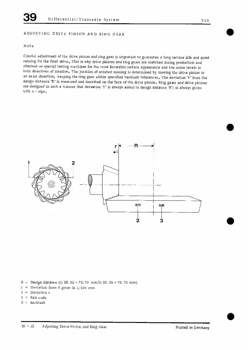
39 Differential/Transaxle System (128
ADJUSTING DRIVE PINION AND RING GEAR
Note
Carelul adjustment of the drive pinion and ring gear is important to guarantee a long service life and quiet running for the final drive. This is why drive pinions and ring gears are matched during production and checked on special testing machines for the most favorable surface appearance and low noise levels in both directions of rotation. The position of quietest running is determined by moving the drive pinion in an axial direction, keeping the ring gear within specified backlash tolerances. The deviation ‘t” from the design dislance ‘R’ is measured and inscribed on the face of the drive pinion. Ring gears and drive pinions are designed in such a manna that deviation “I” is always added to design distance ‘Y; is always given with 3 + sign.
R = Design distance (G 28. 03 = 12.70 mm/G 28.05 = 70.10 mm)
I = Deviation from R given in 1,100 mm 1 = Deviation I
2 z Pair code 3 = Backlash
39 - 12 Adjusting Drive Pinion and Ring Gear Printed in Germany

928 Differential/Transaxle System 39
Recommended Sequence of Adjusting Drive Pinion and Ring Gear
When it becomes necessary to adjust the drive pinion and ring gear. it would be in the interest of econo- mical procedures to keep to the following sequence.
1. Determine the total shim thickness ‘SM.” bearing/differential.
(Sl plus S2) for the specified pre-load of the taper roller
2. Determine shim thickness ‘S “. 3
3. Divide total shim thickness ‘5 tot.” in Sl and S2 so that there is the specified amount of backlash between the ring gear and drive pinion.
The goal of adjustments is to relocate the point of optimal quiet running as was determined in the special testing machine during production.
Perfect results require absolute care and cleanliness during all assembly and measuring operations.
Location of Shims
Sl = Shim for ring gear S2 = Shim for ring gear S3 = Shim for drive pinion
Printed in Germany Adjusting Drive Pinion and Ring Gear 39 -13
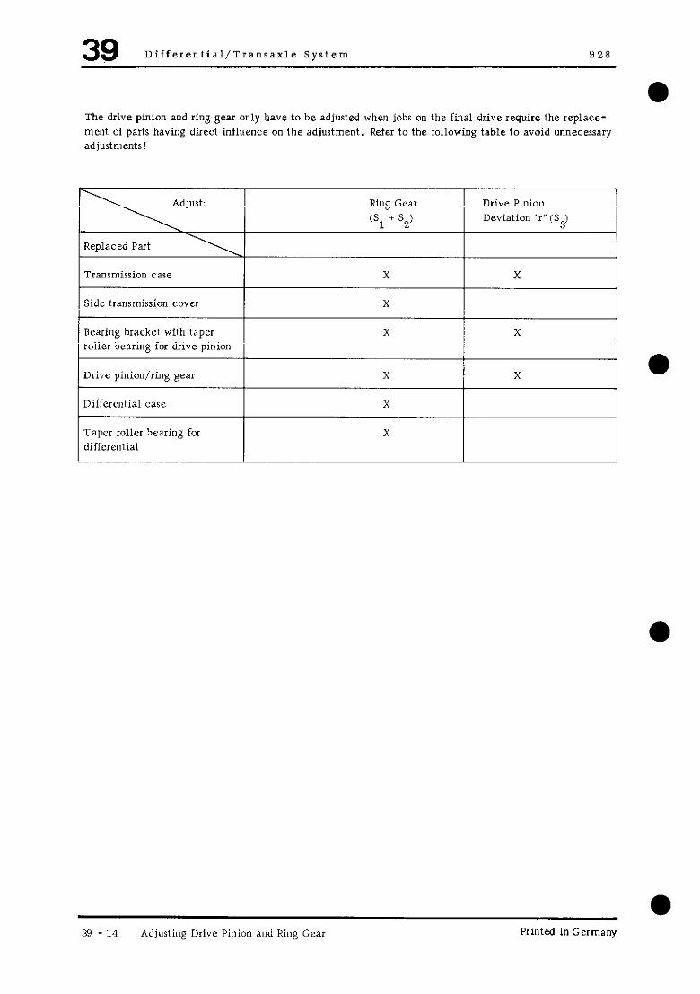
39 Dlfferential/Transaxle System
The drive pinion and ring gear only have to he adjusted when jobs on the final drive require the replace- ment of parts having direct influence on the adjustment. Refer to the following table to avoid unnecessary adjustments!
Transmission case I X
1 Side transmission cover ) x
Bearing bracket with taper roller bearing for drive pinion
X
Drive pinion/ring gear x
Differential case X
Taper roller bearing for
I
x differential
Drive Pinion Deviation “r” (S-)
X
X
X a
39 -14 Adjusting Drive Pinion and Ring Gear Printed in Germany
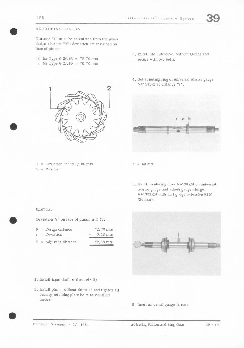
928 ~~lllc,cl,t‘al/TranaaxIc system 39 ADJUSTING PINION
Distance “E” must be calculated from rhe given design disrance “R”+ deviation “r” inscribed on face of pinion.
“R” for Type G 28.03 = 12.70 mm “R” for Type G 28.05 = 70.70 mm
3. Install one side cova without O-ring and
secure with two bolts.
4. Set adjusting ring of universal master gauge VW 385/l at distance ‘“a”
1 2
- a b
- “g=PERaR-
1 = Deviation “r” in l/100 mm 2 = Pair code
a
5.
Example:
Deviation ‘Y on face of pinion is N 18.
R = Design distance 72.70 mm
I = Deviation + 0.18 mm
E = Adjusting distance 72.88 mm
: 6Omm
Install centering discs VW 385/4 on universal master gauge and attach gauge plunger VW 385/14 with dial gauge extension9150
(20 mm).
1. Install input shaft. v&hour circlip.
2. Install pinion without shims S3 and tighten all
hearing retaining plate bolts to specified torque.
6. Insert universal gauge in case.
a Printed in Germany IV. 1980 Adjusting Pinion and Ring Gear 39 - 15

39 Dlfferential/Transaxle System 928
7. Install second side cover without O-ring and ware with two bolts.
8. Use spindle to move centering disc of universal gauge out so that the universal gauge can just barely be turned by hand.
9. Set master gauge VW 385/30 at adjusting distance E (E = R + I)
Example: R = 72.70 mm
I = + 0.18 mm
E = 72.88 mm (adjustment of master gauge)
10. Install master gauge and set dial gauge (3 mm range) at zero with 1 mm pre-load.
0
, 4
* -.
:: u’: I’L Bmr’
&I k.& :-I -*- F”o
11. Install gauge plate VW 385/17 on pinion head.
12. Turn universal gauge carefully until dial gauge extension is perpendicular to face of pinion head. At this moment dial gauge needle will reach its point of reversal and dial gauge should be read.
,-. . c
a
39 - 16 Adjusting Pinion and Ring Gear Printed in Germany
? ;g&,, ;.‘&.? /
j 1; %j I t t wh, ‘,
1 .& .,,, l;;\&- ; : ; ,!
I 4% r

928 Differential / Transaxle System 39
The measured value will always deviate from rhe set distance “E” counterclockwise (small dial gauge) needle positioned between 0 and 1). i. e. when dial gauge is set wirh 1 mm pre-load rhc value deviating from 1 musr be used as shim rhickness s3.
For this measurement the dial gauge I~USI be read anriclockwise (red range).
13. insert a shim wirh thickness ~3 equalling the determined deviation between rhe bearing cap and lransmission case. Round off to the nearerr 0.05 mm (e.g. 0.22 mm becomes 0.25 mm).
14. After installation of shims with the determined thickness,recheck adjusting disrance “E”.
Note
In the interest of economical procedures the coun- tershafr should be insralled in the case before assembly of the drive pinion with determined shims 33.
a Printed in Germany _ 1”. 1980 Adjusring Drive Pinion and Ring Gear 39 - 17

39 Dlfferential/Transaxle System 928
ADJUSTING RING GEAR (Stat.)
The drive pinion must not be installed for this adiustment.
5. Calculate shim thickness Xot.“.
Stat. = gap - 0.30 mm (bearing pre-load)
Example:
Gap 1.25 mm Bearing pre- lOad - 0.30 mm
1. Install differential with ring gear in case. sm. 0.95 mm _----------.
2. Install ride transmission cover (ring gear end) without shims and tighten all bolts to specified torque.
3. Guide in second side transmission cover withouj shims carefully.
4. Check gap between transmission case and side transmission cover with a feeler gauge.
39 - 18 Adjusting Drive Pinion and Ring Gear Printed in Germany

928 Differential/Transaxle System 39
ADJUSTING BACKLASH
1. Install pinion with shims Sg determined for pinion adjustment and tighten bearing re- taining plate bolts to specified torque.
6. Engine 5th and reverse gears. and hold pinion with local manufactured tool on reverse gear. This is done by tightening a screw with a ground point between two teeth.
2. Place differential in case.
3. Install side cover. placing determined shim I m,
““91
“Stotal” on ring gear end. and tighten all bolts to specified torque.
4. Turn differential in both directions several times to settle tapered roller bearings.
5. Install gauges, setting adjustable lever VW 388 to distance “a” 7 SO mm.
1 - Screw M 8 x 80 (ground point) 2 - Flat iron 60 x 20 x 6 mm
Note
when shift rods are installed the engagement of two gears will require removal of detent plunge1 for 1st and reverse gear shift rod.
I. Turn ring gear to stop by hand and set dial gauge at zero.
8. Turn back ring gear and read amount of back- lash (e.g. 0.88 mm).
Printed in Germany Adjusting Pinion and Ring Gear 39 - 19

39 Differe”tial/Transaxle System 928
DETERMINING THICKNESS OF SHIMS S1 AND S2
Note
The measured backlash m”rt be brought to the value specified by the pinion/ring gear ma”“- facturer by dividing “Stotal”.
S 2 = stata - s1
,Example:
Specifications: Getrag pinion/ring gear = 0.15 to 0.20 mm Hurth pinion/ring gear = 0.20 to 0.25 mm
stata
Sl s2 =
a
0.95 mm - 0.16 mm
0.77 mm
The specified backlash is inscribed on the ring
gear. 1. Remove side cover and divide shims “Stotal”
to give the shim thicknesses determined for SI and S2.
% = stat=1 - measured backlash + specified backlash (inscribed on ring gear) X 0.66 (lift consrant)
Note
In the interest of economical procedures the shift rods and shift forks should be installed prior to the assembly of the differential with determined shims S1 and S2.
stata - measured backlash
+ specified backlash (e.g. 0.20 “ml)
X (lift consranr) Sl =
0.20 mm
0.21mm
0.66 0.18 mm
2. Measure backlash and. if necessary. change shims S1 and S2 again until specified backlash is reached.
3. Check backlash at four places by turning ring gear 90’ each time. The four measurements must not deviate from each other by more than 0.05 mm.
a
39 - 20 Adjusting Pinion and Ring Gear II. I979 - Printed InGermany

928 Differential / Transaxle System 39 a TOOLS
a
-. . . ‘.
-_ Y. 1_
3’ 42 -,
, -. pw ,\,
” ‘5
No. Description Special Tool Remarks
1 Transmission holder ‘1162
2 Puller V’s 1018
3 Depth gauge ___ Standard
4 Cenrering pins -__ Made locally
5 Installer --- Made locally (steel pipe 45 x 5 x 40 mm with welded cover and 11 mm dia. bore)
Printed inGermany - 11, 1979 Removing and Installing Final Drive for Automatic Transmission
39 - 21

39 Differential / Tranoaxle System 9 2 R
Jj.~f~$$*---- ,,pz-x- - --.Lq~~‘-x-’
c/“-j, .#qFJ-$-= (I .#I, l
m
co
in
39 - 22 Removing and Installing Final Drive for Printed in Germany

928 Differential, Transaxle System 39
Note When: Special NO. Description QfY. Removing Installing Instructions
1 Nut 12 Torque: 39...46Nm (26 .33 ftlb)
2 Washer 12
3 Final drive 1
4 Shim Se X Note quantity and Redetermine thickness of shims thickness if for installation later “WXSS3ry
5 Nut 1 Engage parking lock Engage parking lock See page 39 -24a and tighten to specified torque. Lock collar of nut
6 Bolt 6 Torque: 27.. 32 Nm (20 23 ftlb)
7 Circlip 6 Position correctly. Hollow ride faces flange
8 Bearing assembly 1 Pull out with a Press in with locally with drive pinion suitable puller made tool
9 Shim X Note quantity and Redetermine thickness of shims thickness if for installation later “NXSXV
10 O-ring 1 Replace, coat with ATF. Make sure that fit is correct when installing final drive
Printed in Germany VI, 1982 Removing and Installing Final Drive for Automatic Transmission
39.23
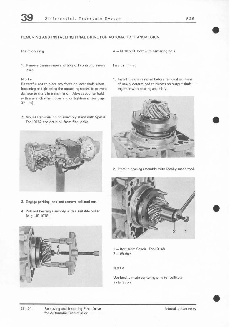
39 Differential, Transaxle System 928
REMOVING AND INSTALLING FINAL DRIVE FOR AUTOMATIC TRANSMISSION
Removing
1. Remove transmission and take off control pressure lever.
Note Be careful not to place any force on lever shaft when loosening or tightening the mounting screw, to prevent damage to shaft in transmission. Always counterhold with a wrench when loosening or tightening (see page 37 - 141.
2. Mount transmission on assembly stand with Special Tool 9162 and drain oil from final drive.
j .‘-. +,r - ,JyqpZ; ,
‘.\, ,;: ~c ? , i .I? 1’ ;?@yj-=q; , *i;. f$ ’ ;” I$-* - .
_. .’ ; +a@-
3. Engage parking lock and remove collared nut.
4. Pull out bearing assembly with a suitable pullel k. g. US 1078).
A - M 10 x 30 bolt with centering hole
Installing
1. Install the shims noted before removal or shims of newly determined thickness on output shaft together with bearing assembly.
2. Press in bearing assembly with locally made tool.
1 -Bolt from Special Tool 9148 2 -Washer
Note
Use locally made centering pins to facilitate installation.
39-24 Removing and Installing Final Drive Printed in Germany for Automatic Transmission
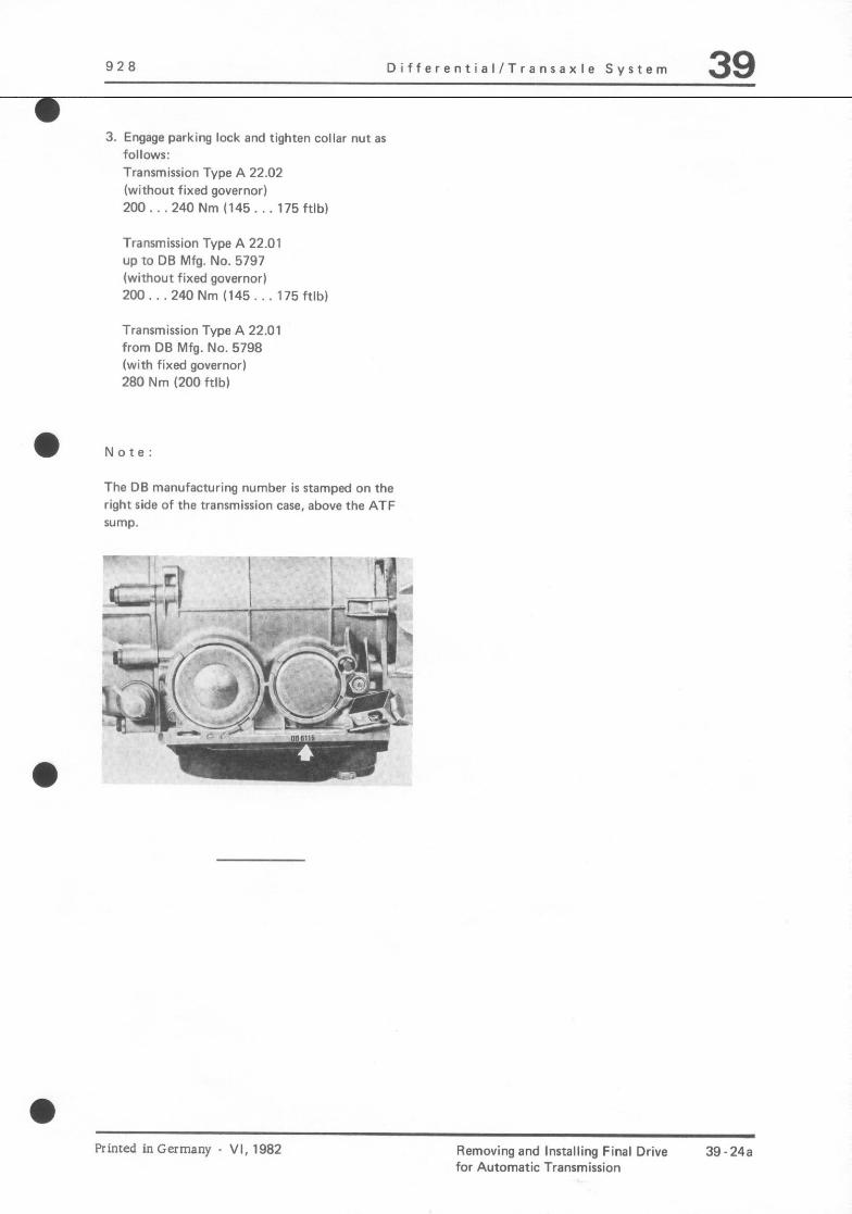
926 DifferentiallTransarle System 39
3. Engage parking lock and tighten collar nut as follows: Transmission Type A 22.02 (without fixed governor)
200...240Nm(145...175ftlb)
Transmission Type A 22.01 up fo DB Mfg. No. 5797 (without fixed governor) 200.. ,240 Nm (145.. 175 ftlb)
Transmission Type A 22.01 from DB Mfg. No. 5796 (with fixed governor) 280 Nm (200 ftlb)
l Note: The DE manufacturing number is stamped on the right side of the transmission case, above the ATF S”lllP.
Printed inGermany - VI, 1982 Removing and Installing Final Drive 39.24a for Automatic Transmission

928 Diflerential / Transaxle System 39 a TOOLS
NO. Description
l 1 separaror
2 Depth gauge
Special Tool
us 1103
___
Remarks
Standard
Printed inGermany _ 11, 1979 Disassembling and Assembling Bearing Assembly 39 25 for Automatic Transmission

39 Dlfferenrial / Trannaxle System 928
31 - 26 Disassembling and Assembling Bearing Assembly Printed in Germany
for Automatic Transmission

928 Differential / Transaxle System 39
NO. Descriprian WY. Nute When Special
Removing Installing Insrrucrionr
1 Bearing flange, 1 For replacemenu only available as complete part (positions 1. 4)
2 Bearing inner race 1 Heat to approx. 120’ C/248’ F and drive on
3 Adjusting ring X
4 Bearing inner race 1 Heat ro appror. 100’ C/212’ F and drive on
5 Pinion 1 Press out with Note pair number V\Y 516
Printed inGermany _ 11, 197,~ Disassembling and Assembling Bearing Assembly 3’1 - 27
for Auromatic Transmission

39 Dlfferenrial / Transaxle SVslem 928
DlSASSEMBLlNG AND ASSEMBLING BEARING ASSEMBLY FOR AUTOMATIC
TRANSMISSION
Disassembling Assembling
1. Press OUI pinion with VW 516.
U- ‘~7-:
-
w---e
Note
Bearing flange is only available as a complere unit (with rapered roller bearings and adjusting ring) for replacements.
1. Hear tapered roller bearing inner race to -
:, approx. 100’ C/212’ F and drive on.
2. Press on assembled bearing with VW 415 a. approx. 5 Kl”S force.
2. Press off tapered roller bearing inner race with a special rool separator US 1103.
3. If necessary. determine rbickness of shims for bearing assembly.
30 - 28 Disassembling and Assembling Bearing Assembly Printed in Germany
for Automatic Transmission
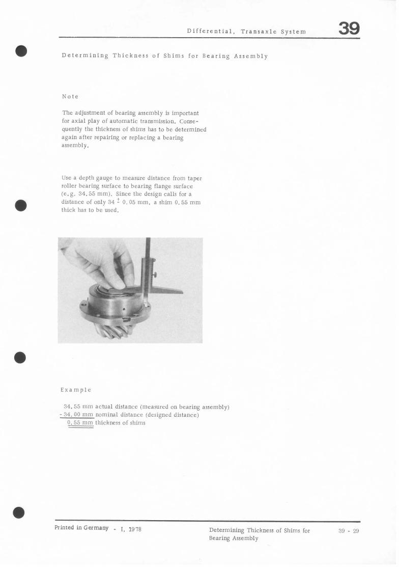
a
a
Differential. Transaxle System 39
Determining Thickness of Shims for Bearing Assembly
Note
The adjustment of bearing assembly is important for axial play of automatic trammission. Conse- quently the thickness of shims has to be determined again after repairing or replacing a bearing assembly.
Use a depth gauge to measure distance from taper roller bearing surface to bearing flange surface (e.g. 34.55 mm). Since the design calls for a distance of only 34 1. 0.05 mm, a shim 0.55 mm thick has to be used.
c . . 1 z i’k’l ‘P
,)
\ E 1 .) b
Examule
34.55 mm actual distance (measured on bearing assembly) - 34. 00 mm nominal distance (designed distance)
0.55 mm thickness of shims
Printed inGermany _ 1, 1978 Determining Thickness of Shims for Bearing Assembly
39 - 29

a
928 Differenrial / TransaxLe System 39 TOOLS
Measuring bar
Xnrering rings
Plunger
Dial gauge extension (25 mm)
Maser micromerer
IO. I
? I I
2 (
3
4
5 1
6
7
8
'I
10
11
12
13
Dial gauge
Dial gauge Standard. 10 mm range
Feeler gauge
Sleeve
Clamping arbor
Adjustable lever
Dial gauge holder
Lever Made locally
Special Tool Remarks
VW 385/l
VW 385/4
VW 385/14
1168
VW 385/30
9145
VW 521/4
VW 388
VW 381
Standard. 3 mnl range
Srandard. 0.05 IO 1.0 mm
a Printed in Germany _ 11, 1979 Adjusting Pinion and Ring Gear
(Auromatic Transmission)
30 - 31

39 Ulfferenlial / Transaxle System
ADJUSTING PINION AND RING GEAR
General Informarion
Accurate adjustments of rbe pinion and ring gear are immensely importanr for the service life and smooth running of rhc final drive. This is why pinions and ring gears are paired during manufacture and checked in special machines for tooth pa!tern and quietness in borh diret:iions of rotation. The position of smoothes1 running is derermined by moving the pinion in an axial direction. whereby the ring gear is lifled out of the no-play meshing poritiou far enough so that the backlash will be kept within specified rolerances. Deviaion “I” from the designed distance “R” in measured and recorded on face of pinion. Ring gears and pinions are designed so rhal deviation “r” is always added to ‘7”. i.e. is preceded by a + sign.
r R----ci +*
!l$-l.
‘.I..
-t ..A I ,
R = Design distance 12.70 mm I = Deviation from R in l/100 mm 1 : Deviarion I 2 = Pair number 3 = Backlash
a 39 - 32 Adjuring Pinion and Ring Gear Printed in Germany
(Automatic Transmission)

928 Differential. Transaxle System 39 a Recommended Sequence for Adjustment of Pinion/Ring Gear
If drive pinion and ring gear have to be adjuted,the following sequence of procedures would be most economical.
1. Determine total shim thickness “Sges” (Sl plus S2) for specified preload of taper roller bcaring/diffcrential.
2. Determine shim thickness “S3”.
3. Divide total shim thickness “Sges” into Sl and S2. so that specified backlash is between ring gear and drive pinion,
Objective of adjustments must be to regain the maximum degree of quiet running, as had been determined by the special testing machine in manufacturing.
a Absolute cleanliness is essential for all assembly jobs and testing procedures to guarantee perfect results.
After working on the final drive it will only be necessary to adjust the pinion and ring gear, if parts had been replaced which have direct influence on said adjustment. The following chart
will help in avoiding unnecessary adjustmentn!
Ring Gear (S1 + S2) Drive Pinion
tomatic) or rear
a Printed inGermany _ 1, 1978 Adjusting Drive Pinion and Ring Gear
(Automatic Transmission) 39 _ 33

39 Differential. Transaxle System 9 28
ADJUSTING PINION
Adjusting distance “E” is calculated from known design distance “R” = 12.10 mm + deviation “I”, which is located on face of drive pinion.
1. Install bearing assembly with shims and tighten collared nut to specified torque.
2. Install final drive case (without shims) and tighten all hexagon nuts to specified torque.
3. Install one side bearing cover without O-ring and secure with two bolts.
4. Adjust setring of Special Tool VW 385/l to distance “a”.
1 = Deviation “1” in l/100 mm 2 = Pair number
Note
The design of the drive pinion will not allow use of the 5 mm thick Special Tool VW 385/17. normally applied for adjustments.
a = 41 mm
Since Special Tool VW 385/30 includes this 5 mm distance, it is important to add 5 mm to adjusting distance “E”.
5. Slide Special Tools VW 385/4 on to 385/l. Install Special Tool VW 385/14 with (25 mm) dial gauge extension 9168.
Example:
N 18 Is the deviation “I” on face of pinion.
R = design distance 12.70 mm r = deviation + 0.18 mm E = adjusting distance 12.88 mm Missing special tool + 5.00 mm Adjustment of master gauge 71.88 mm
-!-q+L~~-*e. -* Ii
a
39 - 34 Adjusting Drive Pinion and Ring Gear Printed in Germany (Automatic Transmission)

9 2 8 Differenrial / Transaxle System 39
6. Turn pinion so that surface of pinion nut is 11. lnsiall measuring bar and set (3 mm range)
vertical. dial gauge ar zero wirh 1 mm preload.
1. lnserr measuring bar into case.
6. lnsrall second side cove1 withoui O-ring and secure with two bolts.
9. Pull out centering ring of measuring bar wirh the spindle so that measuring bar can still just be turned by hand.
10. Set Special Tool VW 385/30 to adjusting distance “E” + 5 mm (for missing Special Tool VW 385/11).
Example:
12. Turn measuring bar carrfully until dial gauge
exrension is vertical I” face of pinion head, At rhis moment dial gauge needle will reach in point of reverse direction, when dial gauge must be read.
3 = 12.70 mm
I= + 0.18 mm
E = 12.88 mm
+ 5.00 mm
11. 88 mm adjustment of
measuring bar
The measured value will always deviate from the set distance in clockwise direction (small needle of dial gauge will be between 1 and 2). i.e. when adjusting the dial gauge with 1 mm preload the value deviating from 1 is added an shim thickness
S3.
hinted inGermany - II. 1979 Adjusting Pinion and Ring Gear (Automaric Transmission)
30 - 35

39 Dlfferenrial 1 Transaxle System
Example:
If small needle of dial gauge is between 1 and 2. and large needle points to 0.40 mm, use 0.40 mm as shim thickness S3 (with 1 mm dial gauge pre- load).
13. Install the determined shim lhickness S between transmission case and final dri?e housing.
14. Recheck disrance after installation of shims v&h determined thickness. A deviation of f 0. 03 mm is permissible.
39 - 36 Adjusring Pinion and Ring Gear Printed in Germany
(Auromaric Transmission)

028 Differential / Transaxle System 39
ADlUSTING RING GEAR (S,,,,l)
1. Clamp final drive housing in a vise, using a suitable fixture.
5. Check gap between transmission case and side cover with a feeler gauge.
A - angle iron bar 6. Calculate shim thickness Stota,
Storal = gap - 0. 30 mm (bearing preload)
2. Install differential with ring gear in housing. Example:
G=P Bearing preload
1.25 mm - 0.30 mm
0.95 mm 3. Install side cover (ring gear end) without shims
and righten all bolts ~0 specified torque.
4. Guide in second side cove1 wirhour shims carefully.
Printed inGermany - II. 1!319 Adjuring Pinion and Ring Gear (Auromatic Transmission)
39 - 37
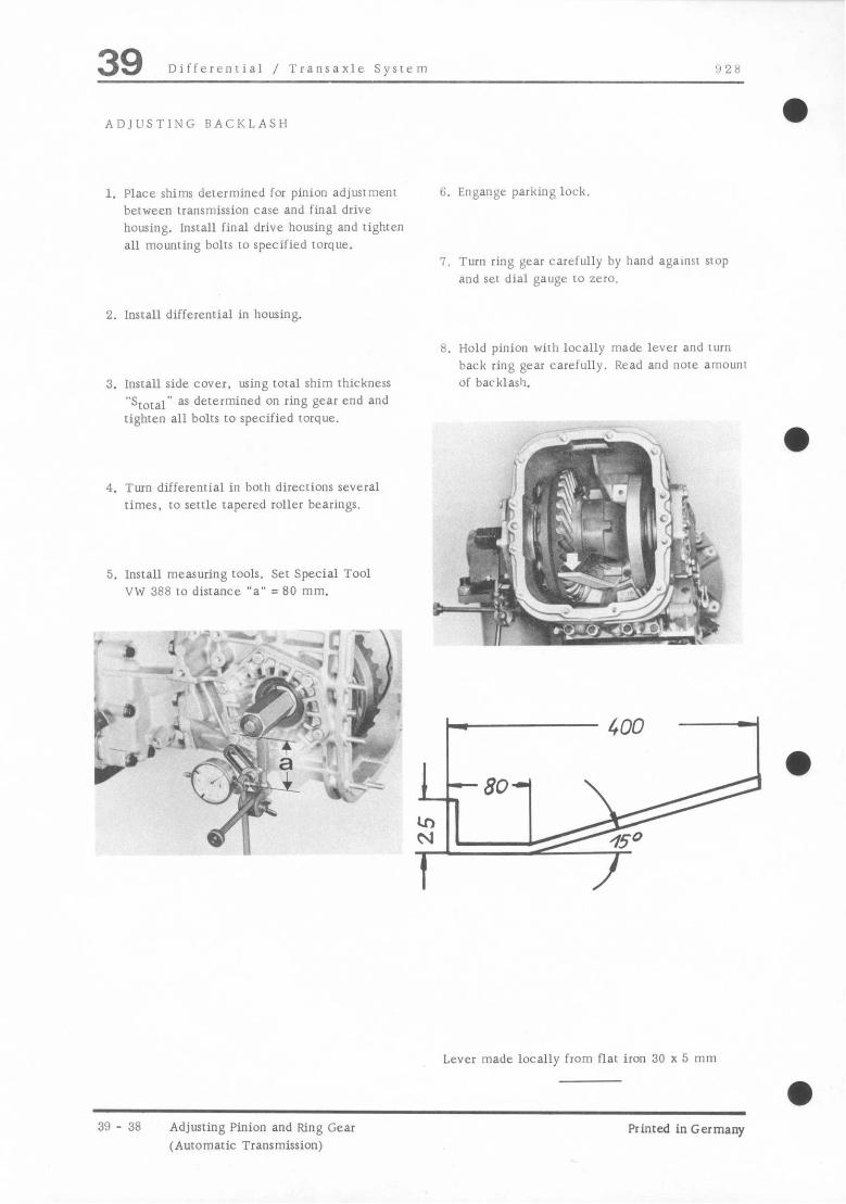
39 Dtfferential / ‘Transaxle System 0 28
ADlUSTlNG BACKLASH 0
1. Place shims determined for pinion adjustment between transmission case and final drive housing. Install final drive housing and tighten all mounting bolts to specified torque.
6. Engange parking lock.
7. Turn ring gear carefully by hand against stop and set dial gauge to zero.
2. Install differenrial in housing.
3. Install side cover. using total shim thickness “S,,tal” as determined on ring gear end and tighten all bolts to specified torque.
8. Hold pinion with locally made lever and turn back ring gear carefully. Read and note amounl of backlash.
4. Turn differential in both directions several times, to settle tapered roller bearings.
5. Install measuring tools. Set Special Tool VW 388 to distance “a” =80 mm.
_ ,, 11-4~ -“: < d : -‘, “,, >’ 1 -,
* - p :
) ‘+F& ; ,t[. i: ‘;$I y+*;,, .$+
i j j. * _ $ --g . - v
r L
‘. J &+c_ 1’ - “43 “S
d
Lever made locally from flat iron 30 x 5 mm
39 - 38 Adjuring Pinion and Ring Gear Printed in Germany (Automatic Transmission)

928 Differential. Tranraxle System 39
DETERMINATION OF SHIMS S1 AND S2
Measured backlash must he brought to value specified by manufacturer of pinion/ring gear by splitting total shim thickness Sges.
Determining Shim Thicknrss S2 (Opposite Ring Gear)
s2 = sqes s1
Specified Value: Getiag pinion/ring gear = 0.15 to 0.20 mm flurth pinion/ring gear : 0. 20 to 0. 2.5 mm
Example:
a Backlash is stamped on ring gear.
sges 0.05 mm
3 - 0.21 mm
0.68 mm
Note
Determining Shim Thickness S1 [Ring Gear End)
The change in backlash by splitting shims Sl and Sz is only an example and doer not have to he made strict according to procedures.
S1 = Sges (total shim thickness) -measured backlash
a
+ backlash inscribed on ring gear
Example:
sgen - measured backlash
t inscribed backlash (e.g. 0.20 mm)
%
1. Remove side transmission cover and split total
shim thickness Sges, that it given the determined
shim thicknesses Sl and S2.
O.D5 mm 0.88 mm Note 0.01 mm
0. 20 mm 0.27 mm
When tightening nuts for side transmission covers. always remember that there is a certain amount of backlash. Never let the drive pinion and ring gear clamp.
Printed in Germany _ 1, 1y78 Adjusting Drive Pinion and Ring Gear (Automatic Transmission)
xl - 39

39 Dlfferrntial. Trantaxle System
2. Measure backlash and, if necessary. change shims S1 and S2 again until specified play is reached.
3. Check backlash at four places on periphery, turning ring gear by 90’ each time. Measare- ments must not deviate from each other by more than 0. 05 mm.
39 - 40 Adjusting Drive Pinion and Ring Gear Printed in Germany
(Automatic Transmission)

928 Differential / Transaxle System 39
fl
hi+
&-- .y+&-
,’ “-i ~. *ii I\. . $$ ;g$*
L :m‘ ,’ I_
<c-” - -p%&
:- -
1 = Automatic transmission 2 = Central tube 3 = Drive plate housing
Printed in Germany- II, 1974 Removing and Insralling Central Tube
(Automaric Transmission)
39 41

39 .. Dlfterentlal / Transaxle Syrrem 928
l REMOVING AND INSTALLING CENTRAL TUBE (AUTOMATIC TRANSMISSION)
Removing
1. Remove battery ground strap.
2. Remove self-locking nuts from spring struts in trunk.
3. Disconnect multiple plugs in spare wheel well and pull out downward.
4. Detach parking brake cable ar fasrener.
5. Remove air cleaner
6. Remove upper mounting screw of drive plate housing.
---- --.- -- ,-
39 - 42 Removing and Installing Cenrral Tube (Auromatic Transmission)
Printed in Germany

!! 28 Diiterentiai 1 I ransazie Sys~t~n 39
a 7. Rrnmvr splarl~ slticld.
?$#f#&& -‘---’ “*-yy-s p __ ‘:” rcT “-$P P ‘* ’ ’ *
p .\
2F
-7 n_ . I.zm I
i % ) ‘,,
_“-. /
-- ’ ’ “.
-I,
I-“’ *,. 2 li
1 44
i- 8 ~-.
..~ tic ‘Q -
44‘“.
--.7 * .---*
P 8, Re,r,uvr lower body IhIXE
-+-Q 1
‘I. Rrnmve enrirc cxhaus~ sysiem. hy wowing bolts 011 cxhausi rmailllold and holder. and ,I,?” pulling exhaust nys~cni WI of ml~hc~ holder.
I
TWO people will he required 10 rerim”~ and install a cornplere cxhausr system
Printed in Germany II, I!Y!, Removing and Installing Central Tube
(Auromaric Transmission) 3!1 - 43

39 Dlfferenrial / Transaxle Sysrcnl 0 28
10. Remove exhaust system hear shields.
11. rkrmve cover for drive plate housing togerher with STBII~ and detach stabilizer bar.
: ..’
13. Mark locarion uf roe eccentric bolls and l rear axle C~OES member for reinstallation
12. Derach feed and rerun lines for ATF cooler and plug bores in COIIV~~IP~ housing.
A - To cooler inlet (bottom connection) B - From cooler ourler (Cop connection)
14. Support transmission on srabilizcr bar with chain ilS 8031 and remove rear axle.
l 39 - 44 Removing and lnsralling Central Tube
~*utomaric Transmission)
Printed in Germany

928 Differenrial. Transaxle System 39
1.5 Remove rear reinforcemenr plare.
1
- _
I
2
^W_’ -. 1
16. Bolt rransmission plate 9163 on universal transmission jack and place underneath rransmusion.
11. Lift transmission and derach holding chain.
Note
When lowering transmission, iI is imporrallr IO he careful rhar the engine check valve for air injection does noi damage rhe brake line.
18. Lower transmission only so far. char selecro% lever cable and cable sleeve on holder can he detached,
19. Detach conrrol pressure cable. Unscrew hall head and locknut. Pull off ruhher grommer and pull out cable irom engine comparrm~nr Be careful not to bend cable.
Printed inGermany - 11. 1978 Removing and lnsralling Central Tube (Auromaric Transmission)
39 - 45
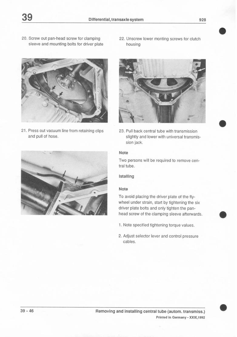
39 DlfferentiaI,transaxlesystem 926
20. Screw out pan-head screw for clamping sleeve and mounting bolts for driver plate
22. Unscrew lower monting screws for clutch housing
21. Press out vacuum line from retaining clips and pull of hose.
23. Pull back central tube with transmission slightly and lower with universal transmis- sion jack.
Note
Two persons will be required to remove can- tral tube.
Note
To avoid placing the driver plate of the fly- wheel under strain, start by tightening the six driver plate bolts and only tighten the pan- head screw of the clamping sleeve afterwards.
1. Note specified tightening torque values.
2. Adjust selector lever and control pressure cables.
39 - 46 Removing and installlng central tube (autom. transmiss.) a
Printed in Germany - XXIX,1992
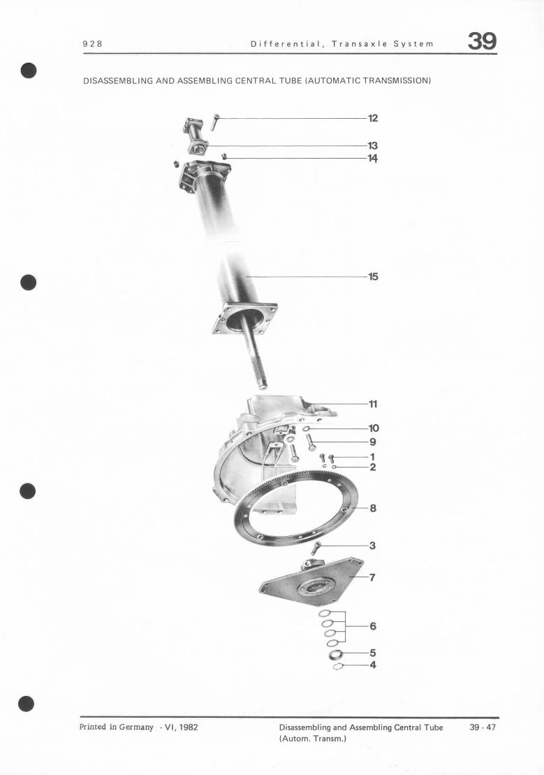
-
928 Differential, Transaxle System 39
DISASSEMBLING AND ASSEMBLING CENTRAL TUBE (AUTOMATIC TRANSMISSION)
,e 7’* a> “$a 13
*gT
14
*\
15
Rimed in Germany -Vi, 1982 Disassembling and Assembling Central Tube (Autom. Transm.)
39 47

39 Dlfferentlal, transaxle system 928
No. Description
1 Bolt
2 Lockwasher
3 Pan head screw
4 Circlip’
5 Bushing’
6 Shim*
7 Driver plate
8 Starter ring gear
9 Bolt
10 Washer
11 Drive plate housing
12 Pan head screw
13 Coupling
14 Dowel sleeve
15 Central tube
Note when Cny. Removing Installing
9 Torque: 32...39 Nm (24 ftlb...29 ftlb)
9 Replace
1 Torque: 80 Nm (59 ftlb)
1 Replace if necessary
1
X
1
1
4 Torque: 39...46 Nm (29 ftlb...34 ftlb)
4
1
1 Torque: Nm 80 (59 ftlb)
1
2
1 Check, replacing if necessary
Note
Parts are deleted as of MY ‘85. Adjustment of the driver plate is no longer required (also refer to page 39 - 138, Vol. Ill).
The ring gear can only be replaced if the central tube has been removed.
39 - 48 Removlng and installing central tube (autom. transmlss.) a
Printed in Germany - XXIX.1992

928 Differenrial / Transanle System 39 a
Checking Drive Shaft
Since the position of the drive shafl is important LO proper operation. the coupling musk protrude by 36 * 0.5 mm.
A = 36+0.5mm
The amount of prorrusion can be corrected by rapping wirb a plastic hammer against face of drive shaft.
Check for easy movcmen~ of drive shaft bearings by ruming shaft by hand. Shaft must turn easily and without binding ar any poinr.
If bearings or shaft are damaged, replace enrire central rube with shaft and bearings. There are no plans for replacement of individual pans.
Printed inGermany - Iv, 1980 Checking Drive Shaft (Automatic Transmission)
39 49
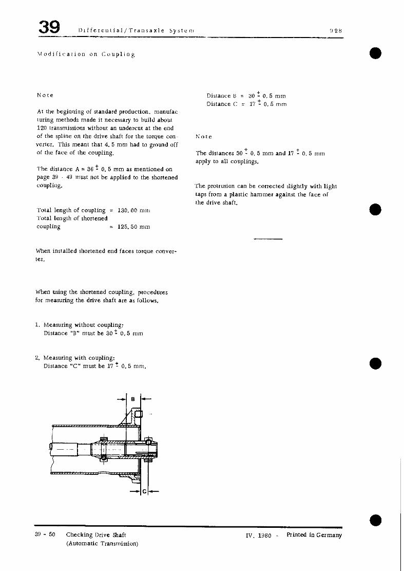
39 I)lfferential/TrailsaxIe systcn !, 28 l__-
hlodiiirarion on Craupling
At the beginning of srandard production, manufac turing methods made ir necessary to build about 120 transmissions without an undercur at the end of the spline on the drive shaft for the torque con- vener. This meant that 4. 5 mm had to ground off of the face of the coupling.
The distance A = 36 r 0.5 mm as mentioned on page 3Y 49 musr not be applied m the shortened coupling.
Total length of coupling = 130. 00 mm Total length of shortened coupling = 125.50 mm
When installed shortened end faces torque convw ter.
When using the shortened coupling, procedures for measuring the drive shaft are as follows.
1. Measuring without coupling: Distance “B” must be 30 i 0.5 mm
2. Measuring with coupling: Distance “C” mutt be 11 + 0.5 mm.
Disrallce B = 30 2 0.5 mm Distance C = 17 t 0.5 mm
ivote
The distances 30 + 0. 5 mm and 11 + 0. 5 mm
apply to all couplings.
The protrusion can be corrected slightly with light raps from a plastic hammer against the face of the drive shaft.
l I 39 - 50 Checking Drive shaft I”, 1980 Printed in Germany
(Automatic Transmission)

928 Differential / Transaxle System 39
Adjusting Drive Plare
To prevent axial loads on crankshaft and consequently addirional loads on crankshaft thrust bearings, the connections between flywheel and drive plate (distance X) must be checked and adjusted after replace- mem of engine. central tube, coupling, front converter housing or drive shaft for converwr.
1 = C&lip 2 = Bushing 3 = Coupling flange 4 = Drive plate 5 = Drive shaft 6 = Engine flywheel 7 = Pre-load 0. 3 + 0.2 mm A = Distance A, engine flange/flywheel mating surface X = Shim thickness (must be determined again)
Printed inGermany _ Iv. 198O Adjusting Drive Plate fAutomatic Transmission)
39 - 51

39 Dtfferenrial / Transaxle System 928 -..
Determining Distance X
1. Crankshaft musr contact thrusr beating in direcrion of transmission. Pry flywheel with a lever until end play of crankshaft is elimmated.
I
I
2. Determine distance A, by using a ruler and measuring distance from engine flange 10 flywheel mating surface.
i 3
Note
Remember thickness of ruler when measuring.
Example,
Measured value 6.1 mm Ruler thickness + 5.5mm
Disrance A 12.2 mm
3. Push coupling on to drive shaft and mount transmission on central tube. Tighten bolts to specified totque.
4. screw in coupling screws by hand (finger tight).
5. Push drive flange with bushing, bur wirhour shims, on to drive shaft and insrall circlip.
6. Use a suitable lever and push drive shaft on drive flange far enough forward so that drive shaft tests on screws on shaft groove.
I. Tighten screw for coupling to specified torque.
39 - 52 Adjusting Drive Plate Printed in Germany
(Auromaric Transmission)
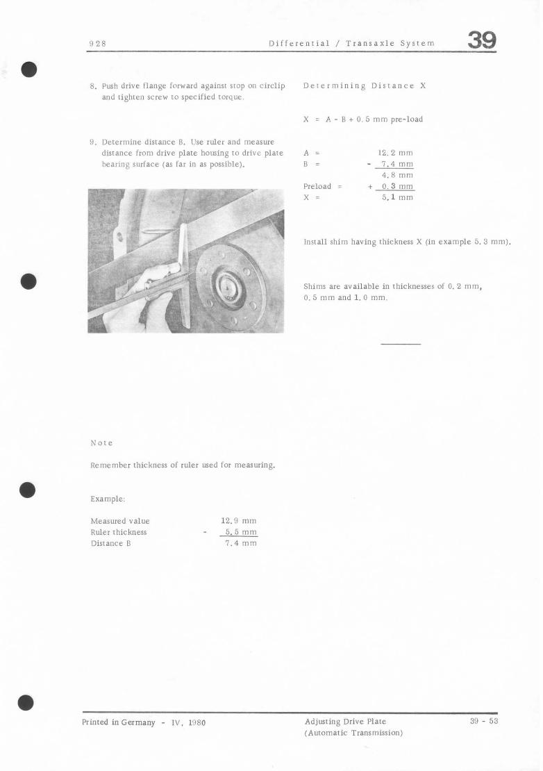
?I28 Differential / Transaxle System 39
8. Push drive flange forward against stop on circlip and tighten screw to specified torque
9. Ikrermine disrance R. Use ruler and measure distance from drive plate housing to drive plate lbeann$ surface (as far in as possible).
Note
Remember thickness of ruler used for measuring.
a Example:
Measured value Ruler thickness Distance B
12.9 mm 5.5 mm 7.4 mm
Determining Distance X
X = A - B + 0. 5 mm pre-load
A = 1%. 2 mm
B = - 7.4 mm 4.8 mm
Preload = )( =
+ 0. 3 mm 5.1 mm
Install shim having thickness X (in example 5. 3 mm).
Shims are available in thicknesses 01 0. 2 mm, 0.5 mm and 1.0 mm.
Printed inGermany - Iv. I!180 Adjusting Drive Plate (Automatic Transmission)
39 - 53

928 Differential I Transaxle System 39 a TOOLS
a
!
No. Description Special Tool Remarks
1 COnlleCtOr __- Local manufacture. Connecror of joint flange can be made of 30 x 15 x 120 mm flat steel and mw have a l/2” square opening in the middle.
Printed in Germany - 111. 1919 Disassembling and Assembling Limited Slip Differential (Locking Ratio 40 70)
39 - 55
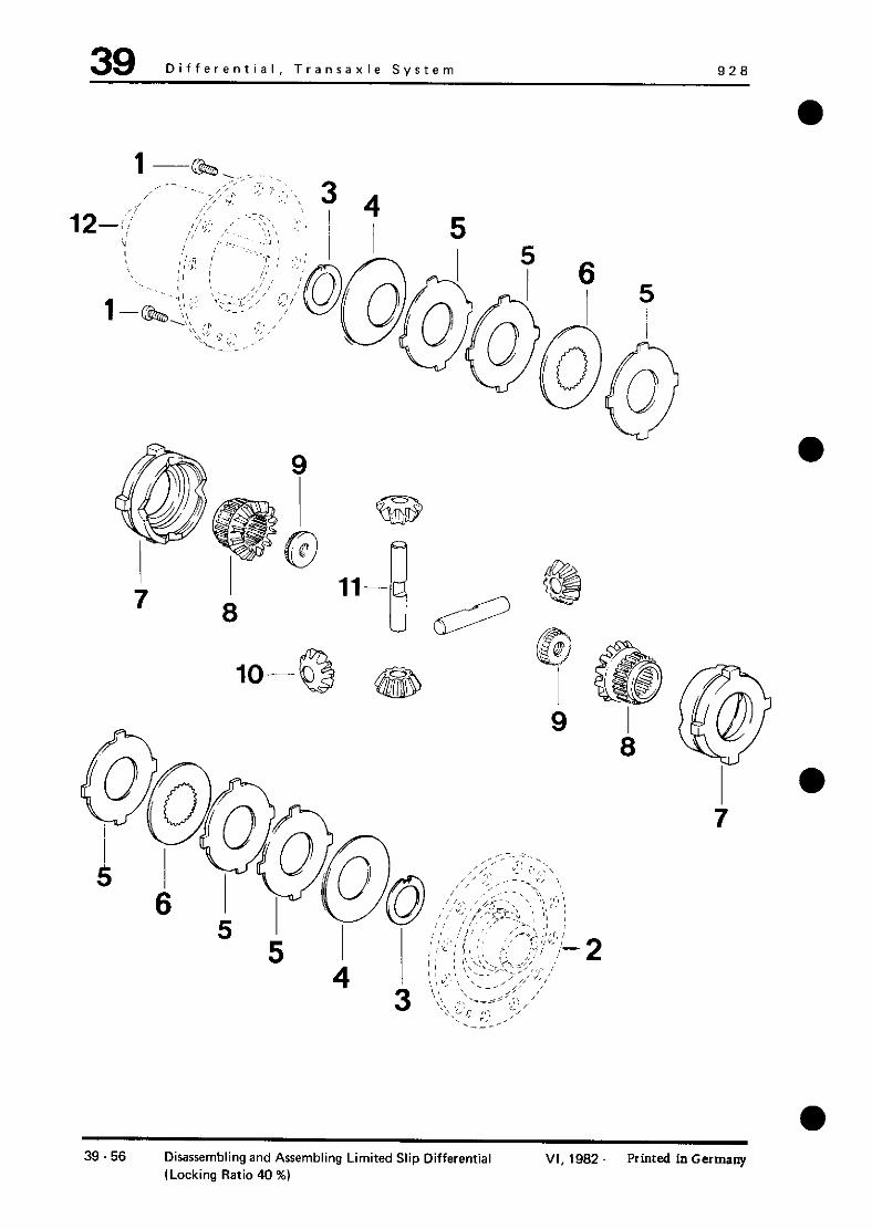
39 Differential, Transaxle System 926
fg$
ll-
II 69 0 ‘“@
9 I 8
39.56 Disassembling and Assembling Limited Slip Differential (Locking Ratio 40 %)
VI, 1962. Printed in Germany

928 Differential, Transaxle System 39
Note When: Special NO. Description Qty. Removing Installing Instructions
1 Bolt 2 Torque: 14 Nm (10 ftlbl
2 Housing cover 1
3 Thrust washer 2 Position correctly
4 Spring retainer 2 Position correctly
5 outer plate 6
6 Inner plate 2 Imolybdenum coated)
7 Thrust ring 2
8 Differential gear 2
9 Splined nut 2 Press O”t of Press in to correct differential fear position
10 Differential pinion 4
11 Differential shaft 2
12 Differential housing 1
hinted in Germany VI, 1982 Disassembling and Assembling Limited Slip Differential (Locking Ratio 40 %)
39.57

39 Differential / Transaxle Sysrem 92R
DISASSEMBLING AND ASSEMBLING LIMITED SLIP DIFFERENTIAL
Disassembling
1. Take off ring gear.
b) Thrusr rings: Guide tabs and bearing surfaces row no! be worn seriously or scored. lo addition. they must move easily in differenrial housing.
c) Differential gears:
2. Loosen screws on housing flange and remove cover.
Bearing surfaces for thrust washers roux not be worn and inner plates must move easily on splines of differential gears.
d) Plater: Check inner and outer platen for wear. Guide tabs of ourer plales and splines of inner plates musk DOI be seriously worn.
2. Lubricate all sliding surfaces of plares. thrust rings and differential shafrs with SAE 90 hypoid gear lube prior 10 insrallarion.
3. Remove all inner parts.
Note
3. Install rhrusr washers so rhar holding tabs engage in bore of housing or housing cover. Applying grease IO [he washers to hold them in position will facilitare insrallarion.
Now order of insralled plates in order LO have same locking ratio when reassembled.
4. lnsrall orher pans as shown in exploded drawing.
Assembling
1. Check all parts for wear or damage and replace, if necessary.
a) Differential housing: Check guide grooves for outer plates and thrust rings for wear.
39 - 58 Disassembling and Assembling Limited Slip Differenrial
Primed in Germany

928 Differential, Transaxle System 39
It is essential that plates be installed in correct order and position to reach the same locking ratio.
Note
Note
If the specified torque cannot be reached, a change can be made by installing pertinent outer plates. Outer plates are available in thicknesses of 1.9, 2.0 and ‘2.1 mm.
Diaphragm springs must be installed so that concave sides face in toward plate assembly.
If the thickest outer plates are installed and the specified torque is still not reached. all plates are worn and must be replaced.
5. Check torque slip with one differential gear held tight and one driven. This requires clamping a flange with two bolts in a vise and installing the differential. Install a second flange with the local manufactured connector and turn the differential with a torque wrench. A torque of 5 to 20 Nm I4 to 14 ftlb) must be reached.
hinted in Germany - VI, 1982 Disassembling and Assembling Limited Slip Differential (Locking Ratio 40 %)
39.59

928 Differential, Transaxle System 39 a REMOVING AND INSTALLING CENTRAL TUBE (Manual Transmission)
REMOVING AND INSTALLING INSTRUCTIONS
Removing 1. Remove front and rear reinforcement plarer.
1. Remove exhaust assembly with hear shields.
2. Remove rear axle.
Note
Let fear axle of can with a bolted battery console hang down on the trailing links and supporr same
(tie up).
3. Remove transmission (see page 34 - 3).
4. Remove clutch (see page 30 - 3).
5. Remove shift lever.
6. Remove ashtray and unscrew guide tube mount from body (only for cars manufactured up IO August 7,1978).
Printed in Germany - IV, 1980 Removing and Installing Central Tube (Manual Transmission)
39 - 61
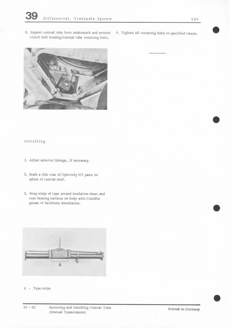
39 Differential, Transaxle System 928
6. Supporr central tube from underneath and remove 4. Tighten a11 mounting bolts to specified torque.
clutch be11 housing/central tube mounting bolts.
Installing
1. Adjust selecror linkage. if necessary.
2. Brush a thin coat of Optimoly HT paste on spline of central shaft.
3. Wrap strips of rape around insularion sheet and coat bearing surfaces on body with Contifix grease t-2 facilitate insrallation.
a
A - Tape strips
a
39 - 62 Removing and Installing Central Tube (Manual Transmission)
Printed in Germany
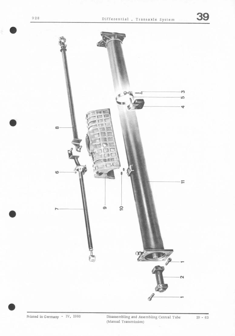
928 Differential , Trannaxle System 39
,&!$7 I,/ \~-’ r- .i
k ,‘.‘yF.,, ‘\ - ,-- I.” \ ) 4 \ \
“>> * -* : : -- : ,- ‘I ‘O
q-; ‘e;yg~;:;~ \ ‘I,, ‘. ?: \ :-
/ -“my . .-- _ p-- e
r hl
‘,, ’ fly w m --
a
Printed inGermany - IV. 1980 Disassembling and Assembiing Central Tube (Manual Transmission)
39 - 63

39 Differential. Transaxle System 928
io. Description WY. Nore When Special
Removing InsraIling Instrucrions
1 Bolt 2 Tighlen to 80 Nm (8. 0 kpm)
2 Double clamp 1
3 Bolt 1
4 Hook with rubber mourn I.
5 strap 1 Mark position for insralling later
6 NM 2 Not for cars pro- duced up to 7. 8.7t
7 Guide tube wirh mount 1 Pry off ailgle joint Coat ball shell and On cars produced and angle joint with suitable ball head of ball up to 7. 8.78 mou
open-end wrench joint while lube paste of guide tube is on and drive on carefully body
8 Selector rod 1
9 Insularion sheet 1 Wrap strips of tape around and coat bearing surfaces to body with Contifix grease
0 Rubber washer 2 Not for cars pro- duced up to 7, 8.7 I
1 Central tube 1 Check, replacing if necessary
a
39 - 64 Disassembling and Assembling Central Tube (Manual Transmission)
Printed in Germany
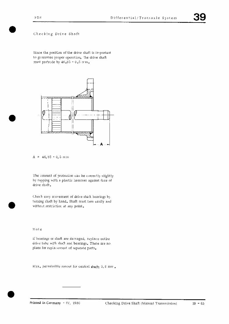
928 Differeniial/Trallsanle System 39
Checking Drive Shaft
Since, the position of the drive shaft is important to guarantee proper ope,ralion. the drive shaft must protrude by 46.85 - 0.5 mm.
* = 46. 8.5 - 0, 5 “,I,~,
The amount of protrusion can be correctly slightly by tapping with a plartic hammer against face of drive rh:ift.
Check easy movement of drive shaft bearings by tlirning shaft by hand. Shaft mu9 turn easily and without restriction at any point.
If bearings or shaft are damaged, replace entire drive tuhc wilb shaft and bearings. There are no plans for replai.ement of separate parts.
Max. permissible runout for cer~tral shaft: 0, E mm.
a Primed in Germany IV. I980 Checking Drive Shaft (Manual Transmissiou) 3 - 65
928 Marker Sheet 39
The procedures described for repairing the 5-speed manual transmission
Type G 28 '85 models onward
are arranged by repair groups and ZOO-series page numbers.
To keep the documents in correct order, please file all pages with ZOO-series page numbers behind the yellow Marker Sheet.
For example: 30 - OZOl....................
34 - ZOl.....................
35 - ZOl.....................
39 - ZOl.....................
Printed in Germany - XVI,1987 39 - 200 A

928 General Data 30
5speed manual gearbox type G 28
.
Tyw Key number Equlpment installed In model
G28llO - 5 Speed 928 S Eur./R.o.W. 1985186
G28Iff - 5 Speed 928 S USA 1985186
G 28112 - 5 Speed 928 S 4 Eur.1R.o.W. 1987166
G 28113 - 5 Speed 926 S 4 USA/Japan 1987188
G 28155’ - 5 Speed 928 S 4 Clubsport i 988 928 54.928 GT i 989/90/9i (worldwide)
G 28l57 - 5 Speed 928 GTS (worldwide)
1992/93
Model ‘88 I89 standard with limited slip differential (40%). As of Model ‘90 standard with controlled limited slip differential (PSD).
B-speed manual gearbox type G 25 Printed in Germany - XXX& 1993
30 - 0201

928 General 30
General Data
Design
Manual transmission Type G 28/10/12/55
Direct transmission with layshaft
Ratios* ihay 32:22
1 st gear 17 ,44 2,5882 1,4545 3,7645
2nd gear 22 38 1,7272 1,4545 2,5122
3rd gear 26 32 ‘1,2307 1,4545 1,790O
4th gear 1 29 127 IO,9310 /1,4545 ! 1,3541
5th gear / direct ~I,0000 !direct 1 1,0000
Reverse gear ~ ;lo) 13) i.2727 ; ,4545 1 3,3056
Final drive I ” Drive pinton without hypoid displacement
Manual transmission Type G 28/l 1 /13
Zl 4 iz ihay iz x ihay 2221 33:21
17 144 12,5882 1,5714 4,0672
22 38 1.7272 ‘1,5714 ‘2,7142
26 32 1,2307 1.5714 1.9339
29 27 0,931O 1,5714 1,4629
Final drive ratio ! 11:30 i = 2,7272 (G28/10/55) ~ 11:29 i = 2,6363 (G28/12)
15:33 i = 2,200
Transmission oil Multigrade gear lube SAE 75 W 90 API - Classification GL 5 (or MIL L 2105 B)
Oil capacities 85 models and earlier = approx. 3,8 liters ! 86 models onward = approx. 4.5 liters
* ZI = Number of teeth on first gear wheel in the load path of the gear concerned
Zz = Number of teeth on second gear in the load path of the gear concerned
iz = Gear ratio
iky = Layshaft ratio
Technical Data Printed in Germany - XX, 1988
30 - 0203
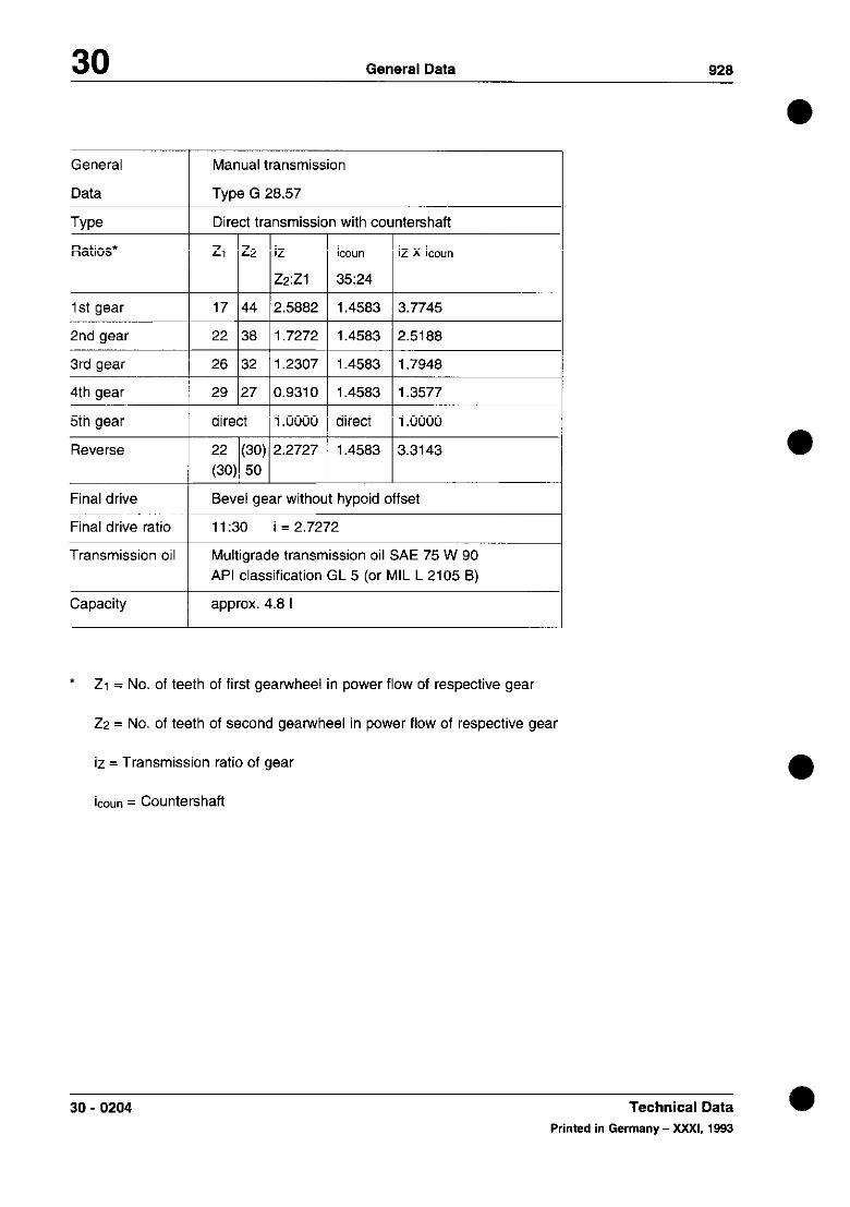
30 General Data 928
General
Data
Type Ratios*
1 st gear
2nd gear
3rd gear
4th gear
5th gear
Reverse
Manual transmission
Type G 26.57
Direct transmissil
ZI 22 iz
Z2:Zl
17 44 2.5882
22 38 1.7272
26 32 1.2307
29 27 0.9310
direct 1 .oooo
22 (30) 2.2727 (30) 50
iC0Un 12 x ihun
3524
i .45a3 I i .3577
direct 1 1 .OOOO
Final drive
Final drive ratio
Transmission oil
Bevel gear without hypoid offset
11:30 i = 2.7272
Multigrade transmission oil SAE 75 W 90 API classification GL 5 (or MIL L 2105 8)
Capacity approx. 4.8 I
* 21 = No. of teeth of first gearwheel in power flow of respective gear
22 = No. of teeth of second gearwheel in power flow of respective gear
iz = Transmission ratio of gear
iCOUn = Countershaft
30 - 0204 Technical Data a Printed in Germany - XXXI, 19%3

928 General Data 30
TORQUE SPECIFICATIONS FOR MANUAL TRANSMISSION G28.10/11
l
Location
Oil filler and drain plug
Transmission output flange
End cover to transmission housing
Side cover to transmission housing
Top cover to transmission housing
Reverse gear stop to top cover
Guide sleeve transmission housing
Back-up light switch to housing
Plug to transmission housing
Selector fork to selector rod
Designation
*Threaded
plug
Hex bolt
Hex bolt
Hex bolt
Hex bolt
Hex bolt
Hex bolt
Back-up light switch
Plug
Hex bolt
Thread/ lead
M 24 x 1.5 M 22 x 1.5
M 10 x 1,5
M 8 x 1,25
M 8 x 1,25
f-1 6 x 1
M6xl
M6xl
M 18 x 1.5
M 12 x I.5
M 8 x 1,25
*Bolts with sealing rings from 86 models onward
Material
8.8
8.8
8.8
8.8
8.8
8.8
5.8
8.8
Torque (Nm)
22
43
22
22
9
9
10
22
19
25
a Printed in Germany - XX, 1988 Torque Specifications 30 - 0205

30 General 928
Torque specification for manual transmission
Location
Cap and hexagon nut on stud for preselector spring
Drive pinion bearing uniU transmission case
Lock nut on drive Dinion
Ring gear/ differential housing
Description
Nut
Bolt-
Nut-
Bolt-
Threads/ Pitch
M14xl
M6x1,25
M 32 x 1,5
M 12 x 1,25
class
10.9
12.9
Torque Nm (ftlb)
50 (36)
30 (22)
300 (217)
165 (119)
30 -0206 Torque specification for manual transmission a
Printed in Germany - XX, 1988

928 Manual Transmission/Controls, Case 34 a
TOOLS
No. Description Special Tool Remarks
1 Holding plate 9149
2 Bracket 9144
3 Impact tool VW 771
4 Extractor 9148
5 Extractor 9140
6 Clamping sleeve Spare part
7 Driver 9223
a Operating lever 9155
9 Centering pins 9321
IO Spring scale Standard, 0...50 N
Printed in Germany . X, ,984 Disassembling and Assemblinq 34 - 201

34 Manual Transmission/Controls, Case 928
DISASSEMBLING AND ASSEMBLING TRANSMISSION
-ir; - 1
\
_ I 3
‘\-----* 4
41- B _\ in _t -=..Y 5 I .
\ II I” -4 n ‘“$4 l3 ‘* - ?spE ,
7 69 68 58
.s”LIL” 80 ,YJ l9 $&I j :’ 1, {i’. 4 \ . / b-f 1;7 .- ” ~I’l-~ l-;p
T T
61 47 ‘1 62 60 6359 40
34 202 Disassembling and Assembling Printed in Germany Transmission
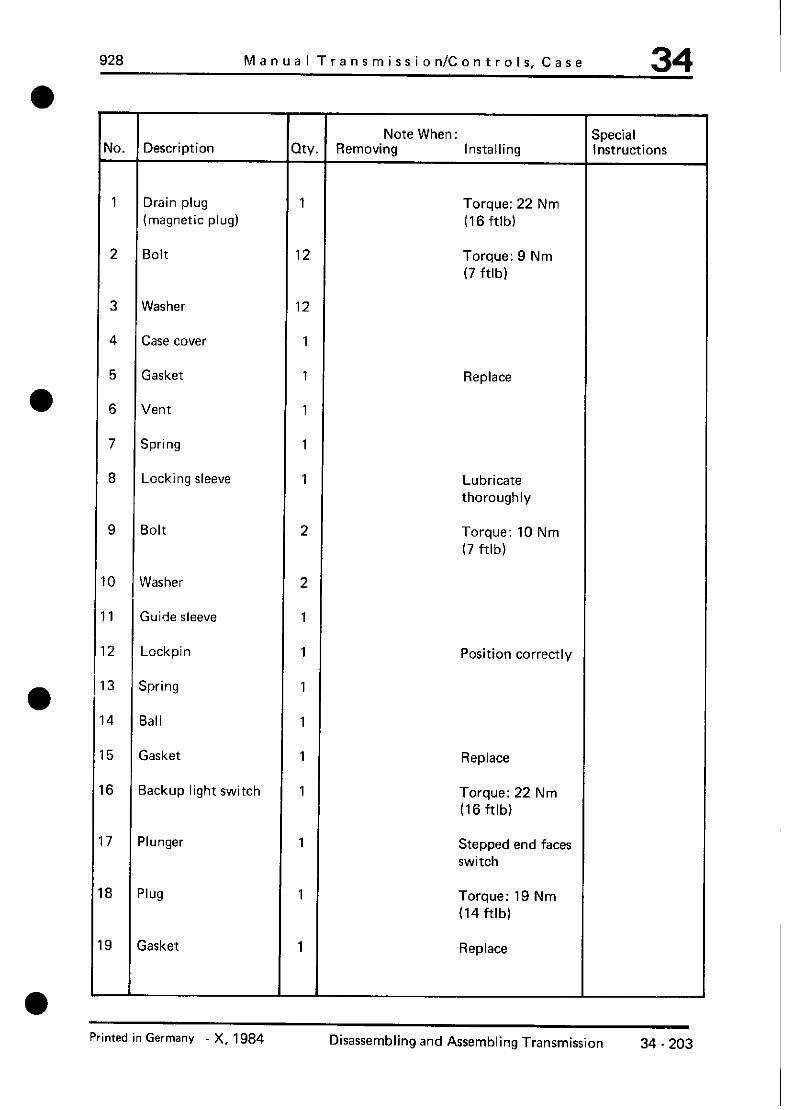
a
a
a
a
928 Manual Transmission/Controls, Case 34
Note When : Special rlo. Description Qty. Removing Installing Instructions
1 Drain plug 1 Torque: 22 Nm (magnetic plug) (16 ftlb)
2 Bolt 12 Torque: 9 Nm (7 ftlb)
3 Washer 12
4 Case cover 1
5 Gasket 1 Replace
6 Vent 1
7 Spring 1
8 Locking sleeve 1 Lubricate thoroughly
9 Bolt 2 Torque: 10 Nm (7 ftlb)
0 Washer 2
1 Guide sleeve 1
2 Lockpin 1 Position correctly
3 Spring 1
4 Ball 1
5 Gasket 1 Replace
6 Backup light switch 1 Torque: 22 Nm (16 ftlb)
7 Plunger 1 Stepped end faces switch
8 Plug 1 Torque: 19 Nm (14 ftlb)
9 Gasket 1 Replace
Printed in Germany X, 1984 Disassembling and Assembling Transmission 34 - 203

34 Manual Transmission/Controls, Case 928
3 Gasket
4 Spring
15 Locking sleeve
I\
2
2
2
2,
2,
2
2
2
2
2!
31
3’
3:
!6 Pin
8 Interior shift rod
9 Shift arm
3 Preselector lever
1 Shift cam
2 Bolt
Qw
1
1
' 1
1
1
1
Note When Special
Removing Installing Instructions
Lubricate thoroughly
Torque: 19 Nm (14 ftlb)
Engage 5th gear and drive out, counterholding shift rod with suitable tool.
Engage 4th gear and drive out, counterholding shift rod with suitable tool.
Replace
Lubricate thoroughly
Counterhold shift rod with suitable tool.
Counterhold shift rod with suitable tool.
Position correctly, cavity for pointed screw must face left.
Torque: 25 Nm (18 ftlb)
a
a
a
34 - 204 Disassembling and Assembling Transmission Printed in Germany
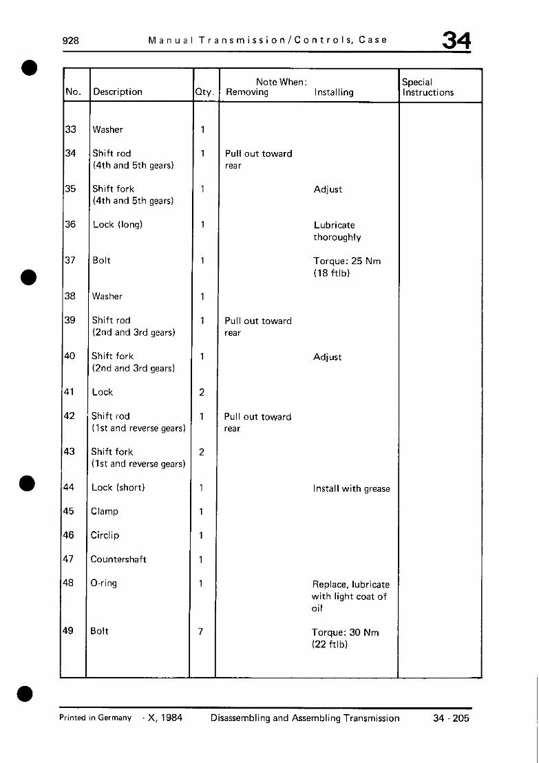
928 Manual Transmission/Controls, Case 34
No. Description Note When: Special
Qty. Removing Installing Instructions
33 Washer 1
34 Shift rod 1 Pull out toward (4th and 5th gears) rear
35 Shift fork 1 Adjust (4th and 5th gears)
36 Lock (long) 1 Lubricate thoroughly
37 Bolt 1 Torque: 25 Nm (18 ftlb)
38 Washer 1
39 Shift rod 1 Pull out toward (2nd and 3rd gears) rear
10 Shift fork 1 Adjust (2nd and 3rd gears)
11 Lock 2
12 ’ Shift rod 1 Pull out toward (1st and reverse gears) rear
13 Shift fork 2 (1st and reverse gears)
14 Lock (short) 1 Install with grease
15 Clamp 1
16 Circlip 1
17 Countershaft 1
I8 O-ring 1 Replace, lubricate with light coat of oil
19 Bolt 7 Torque: 30 Nm (22 ftlb)
Printed in Germany -X, 1984 Disassembling and Assembling Transmission 34 205

34 Manual Transmission/Controls, Case 928
No. Description Note When: Special
Qty. Removing Installing Instructions
50 Lock washer 7 Hollow side faces bearing cap
51 Reverse idler shaft 1 Turn bearing assembly and remove with VW 771
52 Drive pinion 1 Remove with Install with
9144 9144
53 Needle cage 2
54 Thrust ring 1
55 Shim X Note number and If necessary, thickness for determine again reassembly
56 Thrust washer 1
57 Needle cage 2
58 Synchromesh rirg 1 Mark for Check for wear; reassembly mount on same
gear
59 Circlip 1
60 Bearing cap 1 Pull out together with input shaft
61 Input shaft 1 Pull out with 9140and9148
34 - 206 Disassembling and Assembling Transmission Printed in Germany

928 Manual Transmission/Controls, Case 34 l
a
l
No. Description Note When: Special
Qty. Removing Installing Instructions
62 0 - ring 1 Replace, lubricate with light coat of oil
63 Sea I 1
64 Countershaft 1
65 Thrust washer 1 Turning lock faces case opening; stick on case with a little grease
66 Needle cage 2
67 Washer 1
68 Cap nut 1 Torque: 50 Nm (36 ftlb)
39 Nut 1 Torque: 50 Nm (36 ftlb)
70 Preselector spring 1 with stud
71 Take-up sleeve 1 Drive in with 9223
72 Bearing 2 Drive out with Drive in with 9223 suitable mandrel
73 Sea I 1 Drive in with 9223
74 Transmission case 1
Printed in Germany X, 1984 Disassembling and Assembling Transmission 34 207

34 Manual Transmission/Controls, Case
DISASSEMBLING AND ASSEMBLING TRANSMISSION
928
a
Disassembling
1. Mount transmission on assembly stand with Special Tool 9149 and drain oil.
J$,c+a L -& -:’ ’ ---% \, -..
~?C ‘: --’ ~-y?- ----y:.. =>&*.’
&&c -~j I:-. ~~~;-‘: 1.. _ ‘.-S , -,-TI’- .~.
2. Remove differential (see page 39 - 201). Note
3. Remove shift rods, shift forks and locks. Always counterhold on interior shift rod with a suitable tool when driving out pins and kevs.
‘: .d
a
a 34 - 208 Disassembling and Assembling
Transmission Printed in Germany

928 Manual Transmission/Controls, Case 34 a
4. Pull out clamp for reverse gear with a suitable pliers.
5. Unscrew drive pinion mounting bolts, mount Special Tool on bearing assembly and turn until reverse gear shaft can be removed with Special Tool VW 771,
6. Remove circlip for input shaft.
7. Pull out input shaft and bearing cap with Special Tools 9140 and 9148
Note
Always first remove countershaft and lower countershaft to bottom of transmission.
$..,\ “‘FJ
I 1
-2 ?4 ,\, ~.,j
\ + $; pFi’. ,_
\’
Assembling
1. Screw in preselector spring with stud from inside to outside.
r I
A = Preselector spring
Printed in Germany -X, 1984 Disassembling and Assembling 34 209 Transmission

34 Manual Transmission/Controls, Case 928
2. Stick thrust washer for countershaft in case with a little grease.
pqy? p yF!p!y..,” ‘L -q r~ P4
B = Thrust washer
3. Place complete countershaft in case.
Wd,
- r=-:zii.k-J /;I,-- _ . . .---- - -M
R
!y+?. p ’
r ;::I,
_- !*\_’ +-#?e-$~]). “,“.,’ ; if:<; IKij -.I T<<‘,
. . :. ._
c . .~- :
- c- _-..-- --
4. Drive in complete input shaft over bearing outer race against stop alternately with a piece of suitable pipe or a mandrel.
5. Insert O-ring for bearing cap and lubricate with a light coat of oil.
6. Mount bearing cap and circlip.
7. Swing transmission on assembly stand to have input shaft face down.
8. Install needle cages and thrust ring in input shaft.
9. Place svnchromesh ring for 5th gear on clutch bodv.
34 - 210 Disassembling and Assembling Printed in Germany
Transmission

928 Manual Transmission/Controls, Case 34
10. Place reverse gear and needle cages in case as shown in the picture.
11. Screw centering pins, Special Tools 9321, in case for installation of drive pinion and install shims S3.
12. Mount Special Tool 9144 on drive pinion bearing cap and move in drive pinion carefully (with 4th gear engaged). Check that reverse gear is positioned correctly.
A = Soecial Tool 9321
Note
When installing the drive pinion make sure that pins of synchromesh ring (5th gear) engage in openings of guide sleeve.
I
: ~~?.~~~ :... “.&‘
;fjj’
ty&_.- _,_ _ A_r! $&
T
’ 1 f [‘irp-: -~- -< CL? * 9:
Printed in Germany _ x, ,994 Disassembling and Assembling Transmission 34 - 211

34 Manual Transmission/Controls, Case 928
13. Move reverse gear to correct installed position with a suitable tool, remove centering pins 9321 for bearing assembly and turn latter together with shims until the reverse gear shaft can be mounted.
.
14. Drive in reverse gear shaft only far enough that thrust washer can be installed. Then drive in reverse gear shaft to correct installed position and install clamp.
1 = Clamp 2 = Thrust washer
15. Turn bearing assembly and shims S3 to installed position, tighten mounting bolts to torque of 30 Nm and remove Special Tool 9144.
16. Move countershaft to correct installed position and install shaft with O-ring (O-ring coated lightly with oil).
Note
Facilitate installation by turning transmission on assembly stand until countershaft falls into correct installed position on its own weight.
34 - 212 Disassembling and Assembling Transmission Printed in Germany

928 Manual Transmission/Controls, Case 34
17. Install circlip
18. Turn on idle.
19. Install shift rods, shift forks and locks.
-l I- --33- u-t> 1 Is-K,
T- ‘r ‘, 7~ iIpy. -“/,r... irn
’ r v .! _, -
) b --- ‘, TT / “. __’ ,?. I-- -a.3 i r^_ ~ i’ .,, ._: ! “I-‘
~gpy7-++~*~~-~~m7- ,, ,,L-. ,~ .-_ 7-~ -r;c
<- ---7 - .I _
1 - Lock (short) 2 -Shift rods (1st and reverse gears) 3 Locking sleeve (long)
4 -Spring (long) 5 -Plug 6 -Shift rod (2nd and 3rd gears) 7 Locking sleeve (short) 8 -Spring 9 - Lock (long)
10 -Shift rod (4th and 5th gears) 11 - Locking sleeve (short) 12 -Spring (short) 13 -Plug
20. Mount interior shift rod with preselector lever and shift arm, counterholding on shift rod with a suitable tool.
A = Pin
B = Kev
Note
Cavity for pointed screw in interior shift rod must face left (in forward direction).
Printed in Germany - X, 1984 Disassembling and Assembling Transmission
34 -213

34 Manual Transmission/Controls, Case 928
a 21. Install lockpin in correct position.
22. Adjust preselector spring and shift forks (see page 34 - 215).
a 34-214 Disassembling and Assembling Printed in Germanv
Transmission
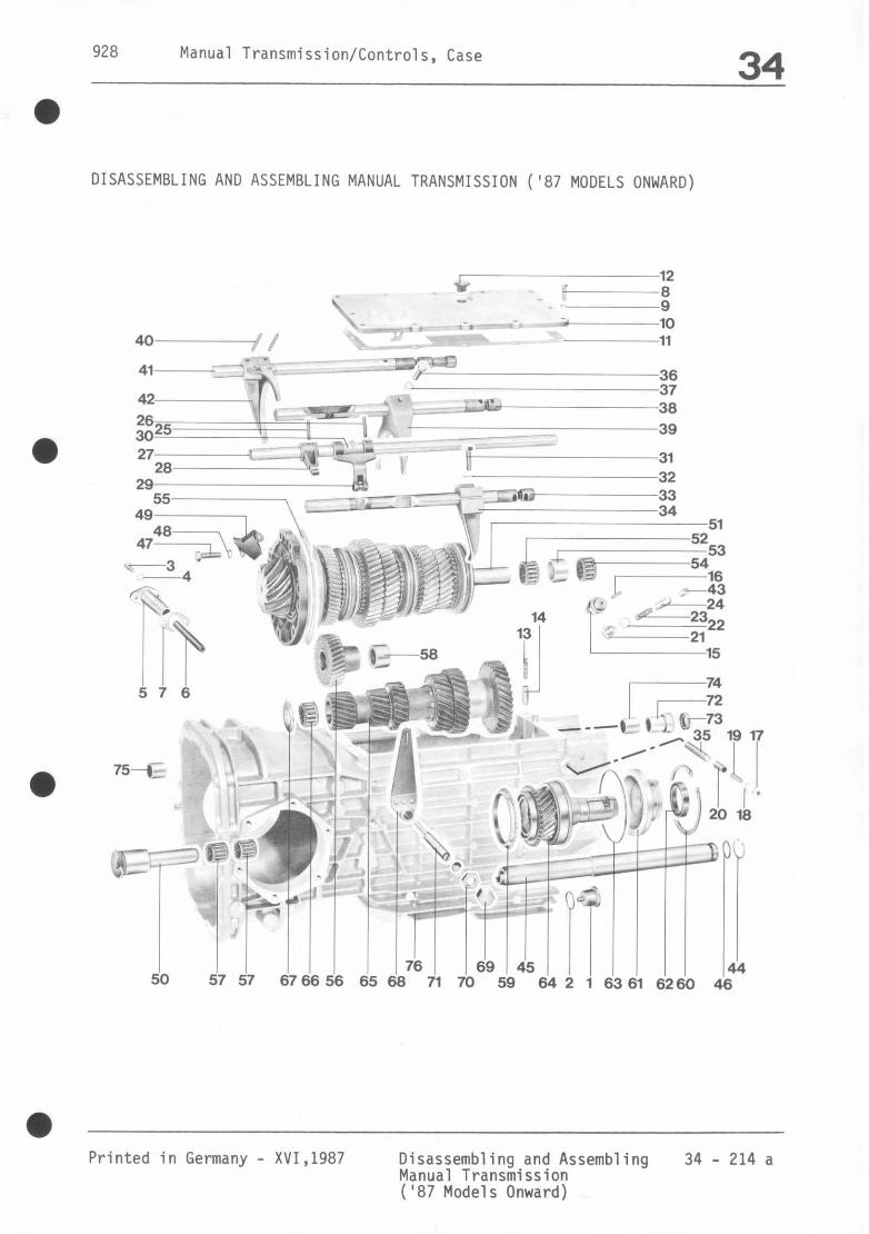
928 Manual Transmission/Controls, Case 34
DISASSEMBLING AND ASSEMBLING MANUAL TRANSMISSION ('87 MODELS ONWARD)
NW I 12
G : x; --* -~~~~ 4 - 1 r 10
40 I P 11
41 in--,_- -~ .:Gc-
36
42 37
g25
27
6260 46
Printed in Germany - XVI,1987 Disassembling and Assembling 34 - 214 a Manual Transmission ('87 Models Onward)

34 Manual Transmission, Operation, Housing 928
No. Description
1
2
3
Threaded plug (with mag-
net)
Sealing ring
Hex bolt
4 Washer
5 Guide sleeve
6 Compression spring
7 Gasket
8 Hex bolt
9 Spring washer
10 Case cover
11 Gasket
12 Breather”
13 Compression spring
14 Locking sleeve
15 Back-up light switch
16 Tappet
17 Threaded plug
18 Sealing ring
19 Compression spring
20 Locking sleeve
3ty.
1
1
2
2
1
1
1
12
12
1
1
1
1
1
1
1
1
1
1
1
l- Note when: Removing nstalling
Clean, tightening torque 22 Nm (16 ftlb)
Replace
Tightening torque:
10 Nm (7 ftlb)
Replace
Tightening torque: 9 Nn
(6.6 ftlb)
Replace
Oil well
Tightening torque:
22 Nm (16ftlb)
Offset side toward
switch
Tightening torque:
19 Nm (13.9 ftlb)
Replace
Oil well
* Transmission housing fitted with new breather as of MY ‘92 (refer to page 34 - 214m)
34 - 214b Dlsassambling and assembling manual transmission (‘87 models onward) a
Prinled in Germany - XXXI, 1993

928 Manual Transmission, Operation, Housing 34
Note
Once the selector rodas are in position, se-
cure the oil funnel at mounding holes “A”.
,-. ;
/# ,<r>yh
_d *
I 4::” -, -
~_,. _ a- 1, I , ‘\,. ,%,; :L
/ ..I,. ; y-b ; :
4 c. ,-,, c ;- 1, 1’ _1 0 I’ :,
:,P i -,_ ‘. . + -yF-; ‘1, I,” ,
.I I-.. _.-- I
Modlflcatlon as of MY ‘92 As of MY ‘92, an oil catcher spray tube is
fitted in addition to the oil catcher cone.
A = Oil catcher cone B = Oil catcher spray tube
14. Place layshaft in installation posfiion and
install axle with O-ring (lightly oil O-Ring).
Note
to faciliatate assembly, turn the transmission
on the support until the weight of the layshaff
causes ist to fall into the installation position.
, --Y” 9 1.
-. c-.
/r r’
,e .*~ 4,E..i,
,.
15. Install circlip.
16. Select neutral.
17. Install preselect spring, selector rods, se-
lector forks and detente.
Schaltgetrlebe zerlegen und zusammenbauen (ab Mod. ‘87) Printed in Germany - XXXI, 1993
34 - 214k

34 Manual Transmission/Controls, Case 928
a
Note:
The blind hole for the tapered bolt in the internal selector arm must face left (as viewed in the forward direction of travel).
19.Adjust preselect spring and selector forks (see Page 34 - 215)
i - Lock, short 2 - Selector rod, 1st and reverse
gear 3- Locking sleeve, long 4 - Compression spring, long 5 - Threaded plug 6 - Selector rod, 2nd and 3rd gear 7 - Locking sleeve, short 8 - Compression spring 9 - Lock, long 10 - Selector rod, 4th and 5th gear 11 - Locking sleeve, short 12 - Compression spring, short 13 - Threaded plug
18.Install internal selector arm with preselect lever and selector finger. Hold selector rod with a suitable tool.
A = Tensioning pin B = Tensioning sleeve
34 - 214 1 Disassembling and Assembling Manual Transmission ('87 Models Onward)
Printed in Germany
a

928 Manual Transmission, Operation, Housing 34
Modifications as of Model Year ‘92
The transmission breather in the upper
transmission cover has been deleted. The
new breather is located in the transmission
housing and is sealed with an O-ring.
A = Breather
B = O-ring (apply a thin coat of transm. oil)
Note
l Observing correct position, push breather into
the housing until it is seated against the stop.
The breather bore must then point forward at
an angle of 45 deg. to the direction of travel.
./-‘- \ 2-x
I
:A @ I he
/
a Dismantling and assembling manual transmission (as of MY ‘87) 34-214m Printed in Germany - XXXI, 1993

928 Manual Transmission/Controls, Case 34
Note When: No.
21
22
23
24
25
26
27
28
29
. ::
32
33
34
35
Description
Threaded plug
Sealing ring
Compression spring
Locking sleeve
Tensioning pin
Tensioning sleeve
Internal selector arm
Selector finge
Preselect 1 ever
Selector cam
Hex bolt
Spring washer
Selector rod (4th and 5th gear)
Selector fork (4th and 5th war)
Lock (long)
Qty.
1
1
1
1
1
1
1
1
1
1
1
1
1
1
1
Removing Installing
Select 5th gear and drive out. Hold selector rod with suitable tool while driving out.
Select 4th gear and drive out. Hold selector rod with suitable tool while driving out.
Tightening torque: 19Nm (13.9 ftlb) replace
Oil well
Hold selector rod with suitable tool.
Hold selector rod with suitable tool.
Blind hole for taper bolt must point to left.
Tightening torque: 25 Nm (18 ftlb)
Withdraw toward rear
Adjust
Oil well
Printed in Germany - XVI,1987 Disassembling and Assembling 34 - 214 c Manual Transmission ('87 Models Onward)

34 Manual Transmission/Controls, Case 928
-
No,
36
Description
Hex bolt
37
38
39
40
41
42
43
44
45
46
Spring washer
Selector rod (2nd and 3rd gear)
Selector fork (2nd and 3rd war)
Tensioning sleeve
Selector rod (1st and reverse gear)
Selector fork (1st and reverse gear)
Lock (short)
Circlip
Layshaft
D-ring
47 Hex bolt
48 Locking washer
49
50
51
-
3il funnel
Reversing shaft
Drive pinion
ty.
1
1
1
1
2
1
1
1
1
1
1
7
7
7
1
1
T Removing
l Note When:
c
Installing
Tightening torque: 25 Nm (18 ftlb)
I Withdraw toward rear
I tdjust
a
I dithdraw toward rear
I 3rease before installing
I ?eplace, oil lightly
Tightening torque: 30 Nm (22 ftlb)
iollow side toward I learing cover
E I qote installation losition
Turn bearing assembly and remove with VW 771
Remove with Special Tool 9144
Install with Special Tool 9144
a
34 - 214 d Disassembling and Assembling Manual Transmission ('87 Models Onward)
Printed in Germany

928 Manual Transmission/Controls, Case 34
No.
52
53
54
55
56
57
60
61
62
63
64 Input shaft
65 Layshaft
66 Needle cage
67 Thrust washer
Description
Needle cage
Thrust ring
Needle bearin'
Shim "S3"
Reverse idler
Needle cage
Spacer
Synchromesh ring
Circlip
Bearing cover
Sealing ring
O-ring
c
9
I
-
NY
i-
1
1
X
1
2
1
1
1
1
1
1
1
1
1
1
-
T Note When: Removing Installing
Note number and thick- ness for reassembly
Mark for reassembly
Withdraw with two flat pliers
Lower layshaft on to base of transmission and withdraw with Special Tools 9140 and 9148
Recalculate if necessary
Check for wear, install with original gear
Oil sealing lip
Replace, oil lightly
Anti-twist lock toward recess in case, hold in place with blob of grease on case.
a
Printed in Germany Disassembling and Assembling 34 - 214 e Manual Transmission ('87 Models Onward)
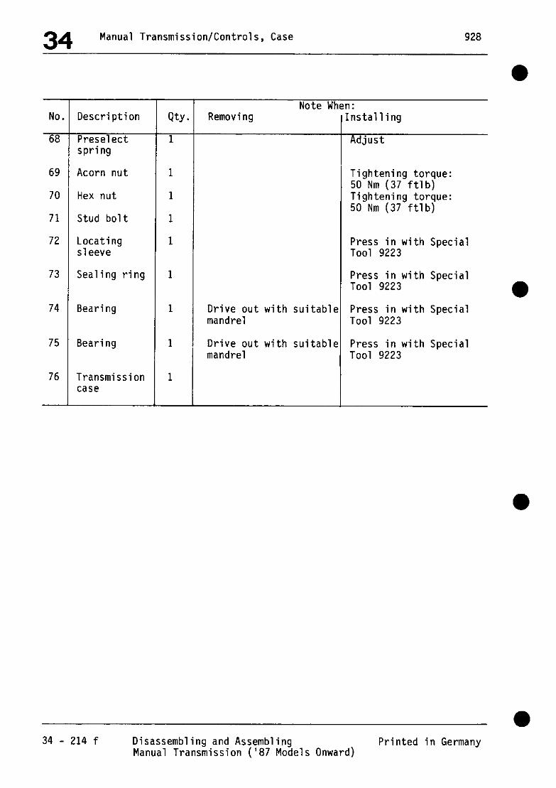
34 Manual Transmission/Controls, Case 928
Note When: No,
xi
69
70
71
72
73
Description
Preselect spring
Acorn nut
Hex nut
Stud bolt
Locating sleeve
Sealing ring
74 Bearing
75 Bearing
76 Transmission case
-
WY,
1
1
1
1
1
1
1
1
1 1
Removing
Drive out with suitable mandrel
Drive out with suitable mandrel
nstalling
Adjust
Tightening torque: 50 Nm (37 ftlb) Tightening torque: 50 Nm (37 ftlb)
Press in with Special Tool 9223
Press in with Special Tool 9223
Press in with Special Tool 9223
Press in with Special Tool 9223
34 - 214 f Disassembling and Assembling Manual Transmission ('87 Models Onward)
Printed in Germany

928 Manual Transmission/Controls, Case 34
NOTES ON ASSEMBLING AND DISASSEMBLING
Disassembling
l.Secure transmission to assembly support with Special Tool 9149 and drain oil.
< Ti / A., .@J “+>- a% ~ -.
. T.-- s ,\ -- _- -~
t;~~-‘.‘ - ..--, ‘.“r . ,.Tr ‘,-’ f ] ‘. _ ; - ::’
Z.Installing differential, see page 39 - 201.
3.Remove selector rods, selector forks and detente.
Printed in Germany - XV1,1987 Disassembling and Assembling 34 - 214 g Manual Transmission ('87 Models Onward)
Note:
When driving out tensioning pin and tensioning sleeve, it is essential to hold internal selector arm with a suitable tool.
F---“-- --‘W /’ ‘/

34 Manual Transmission/Controls, Case 928
4.Remove mounting bolts for drive pinion, secure Special Tool 9144 to bearing assembly and turn the latter with shims "S the reverse idler sh d
' until ft can be
removed with Special Tool VW 771.
. . _
+ $,p: .
C‘.\ P, t
J c. ===B
5.Remove circlip for bearing cover and remove cover with two suitable flat-nosed pliers.
6.Withdraw drive pinion with Special Tools 9140 and 9148.
Note:
It is essential to remove the layshaft axle beforehand and lower layshaft to bottom of transmission.
Assembling:
l.With a blob of grease, fix thrust washer for layshaft to case.
2.Place fully assembled layshaft case.
I
in l
34 - 214 h Disassembling and Assembling Printed in Germany Manual Transmission ('87 Models Onward)

928 Manual Transmission/Controls, Case 34 a
3.Working on each side alternately, use a suitable piece of pipe or a mandrel to drive fully assembled input shaft over bearjng outer race as far as it will go.
9.Place reverse idler with needle cages and spacer in case as illustrated.
0 0 0 1
4.Insert O-ring for bearing cover, oil lightly.
5.Install bearing cover and circlip.
0
\ I
lO.Screw centering pins 9321 for
6.Swivel transmission on support until input shaft points downward.
installation of the drive pinion into case and place shims "S3" in position.
7.Install needle cage and thrust washer in input shaft.
8.Place synchromesh ring for 5th gear on clutch body.
a
Printed in Germany - XVI,1987 Disassembling and Assembling 34 - 214 i Manual Transmission ('87 Models Onward)

34 Manual Transmission/Controls, Case 928
ll.Attach Special Tool 9144 to drive-pinion bearing cover and carefully insert drive
P inion
(with 4th gear selected . Note position of reverse idler.
12.With a suitable tool, move reverse idler to installation position, remove centering pins 9321 for bearing assembly and turn the latter with shims until the reverse idler shaft can be installed.
--pqq ,,
v A+gj;:-+v/ .- “.$ygy?+... ‘;‘;, ,,’ j
; $&@~,!^I ” ‘;::?2 ;, .’ :. b _
A = Special Tool 9321
Note:
When installing drive pinion, it is essential to ensure that the dogs of the synchromesh ring (5th gear) engage the recesses of the guide sleeve.
13.Turn bearing assembly with shims "S " to assembly position, tighten mounting bolts to 30 Nm (22 ftlb) and remove Special Tool 9144.
a
34 - 214 j Disassembling and Assembling Printed in Germany Manual Transmission ('87 Models Onward)

928 Manual Transmission/Controls, Case 34
ADJUSTING SHIFT FORKS
Note
Insert locking sleeve and spring for no-play arrest of 2nd and 3rd gear rod and move to correct installed position with a locally manufactured holder.
c
A = Locally manufactured holder made of 10 x 20 x 45 mm flat steel, with 6.5 mm dia. mounting hole and 2.5 mm chamfer in area of locking sleeve.
1. Adjust operating sleeves with the shift
l forks that they are exactly in the middle between synchromesh rings in neutral
position.
2. Tighten mounting bolts with torque of 25 Nm (18 ftlb).
Note
Deviations in adjustments must be corrected after checking the shifting, since perfect synchronization depends on this.
Printed in Germany . X, 1984 Adjusting Shift Forks 34-215

928 Manual Transmission/Controls, Case 34
ADJUSTING SHIFTS
Note
Insert locking sleeve and spring for no-play arrest of 2nd and 3rd gear shift rod and move to correct installed position with a locally manufactured holder (see page 34 - 215).
34567
1 - 2- 3- 4. 5- 6- J-
Adjusting pin Preselector spring Shift rod, 4th and 5th gears Preselector lever Interior shift rod Shift arm Shift rod, 2nd and 3rd gears
1. Adjust preselector spring (2) with adjusting pin (1) enough that it just barely touches the roller of preselector lever (4). In this position shift arm (5) and preselector lever (4) will engage in openings of 4th and 5th gear shift rod.
2. Measure force of preselector spring. Nominal value: 22 N. Mount Special Tool 9155 on interior shift rod, attach a conventional spring scale (0 . . . . . . . 50 N) below ball, pull interior shift rod and shift arm into 2/3 shift plane and read spring force from spring scale.
3. If necessary, adjust force of preselector spring to 22 N by turning the adjusting pin.
- --dL#
Printed in Germany -X, 1984 Adjusting Shifts 34-217

34 Manual Transmission/Controls, Case 928
4. Move shift arm into 2/3 shift plane and adjust it by turning adjusting pin (approx. l/2 turn clockwise or anticlockwise) that it does not protrude completely into opening of 2nd J 3rd gear shift rod.
r,. i .‘y -ny-
,’ i’ ,.
- ‘9. ~,.==i- I;;
1 _ “:c-, ,,
I’ r- : > ~ .<
.-,, _. AL- ,
,-. ..;-
‘! AH :~ ..-
‘1. L- -2:
5. Check by shifting in and out of all gears carefully with Special Tool 9155 (turning drive pinion if necessary) and note, whether shift arm has access to 4th/5th gear shift rod and lst/reverse gear shift fork in 2/3 shift position as well as access to 2nd13rd gear shift rod in 4/5 shift position
Note
Deviations must be corrected accurately after checking shifts, since perfect shifting depends on correct adjustment.,Turning the adjusting pin (1) will change the force of preselector spring (2). so that turning the adjusting pin for corrections should be kept to a minimum fapprox. l/2 turn clockwise or anticlockwise).
34-218 Adjusting Shift Printed in Germany

928 Manual Transmission/Controls, Case 34
ADJUSTING GEARSHIFT ('86 MODELS ONWARD)
Note:
To lock the 2nd and 3rd gear selector rod in its zero position, install locking sleeve and compression spring and bring to installation position with improvised holder (see page 34 - 215).
3456 7
3456 7
. i ‘.
‘87 models onward
2.Carry out rough adjustment of preselect spring (2). To do so, screw adjustor pin (1) into case until approx. 20 mm project.
'86 Models
1 - Adjusting pin
2 - Preselect spring
3 - Selector.rod, 4th and 5th gear
4 - Preselect lever
5 - Internal selector arm
6 - Selector finger A = approx. 20 mm
0 7 - Selector rod, 2nd and 3rd gear
-
Printed in Germany - XVI.1987 Adjusting Gearshift 34 - 218 a ('86 Models Onward)

34 Manual Transmission/Controls, Case 928
3.Select 3rd gear and with a feeler gage, adjust play s = 0.2 + 0.1 mm between selector finger and 4/5 selector rod. Adjustment is by means of adjuster pin (1).
4.Measure spring force of preselect spring. Specified force 60...SON. To measure, attach Special Tool 9155 to internal selector arm, attach commercially available spring balance (O...lOON) beneath ball, pull internal selector arm with selector finger to l/R shift level and read spring force from spring balance.
'86 models '86 models
'87 models
'87 models onward
a
34 - 218 b Adjusting Gear-shift ('86 Models Onward) Printed in Germany

928 Manual Transmission /Controls, Case 34
5.If necessary, turn adjusting pin to set force of preselect spring to specified value.
Note:
If the spring force is changed, recheck the clearance s = 0.2 + 0.1 mm between selector finger and selector rod and readjust if necessary (see Step 3).
6.As a check, select each gear in turn with Special Tool 9155 (turn drive pinion during this procedure) and ensure that all the gears can be selected in the correct manner.
Printed in Germany - XVI, 1987 Adjusting Gear-shift 34 - 218 c ('87 Models Onward)

928 Manual Transmission/Controls, Case 34
DISASSEMBLING AND ASSEMBLING UPPER TRANSMISSION COVER
6 1
A ~-. ~--
P0' -
I--- /
,q
c
i fL
3 T :I
2
vo. Description Qty. Note When:
Removing Installing Special Instruction:
1 Vent 1
2 Bolt 2 Torque: 9Nm (7 ftlb)
3 Washer 2
4 Gear arrest 1 Check that locking paw1 moves easily
5 Leaf spring 1 Install in correct position
6 Case cover 1
a
Printed in Germany - X, 1984 Disassembling and Assembling Upper 34-219 Transmission Cover with Reverse Gear Arrest

34 Manual Transmission/Controls, Case
DISASSEMBLING AND ASSEMBLING UPPER TRANSMISSION COVER ('87 MODELS ONWARD)
No. Description
1 Air bleed
2 Hex bolt
3 Spring washer
4 Gear lock
5 Leaf spring
6 Circlip
7 Roller lever
8 Case cover
6
- q-9 5 /& 7
6 4 -g!?
a-! I
: ’
-
Qtr
1
2
T Removing
Note When: Note When: Installing Installing
Tightening torque 9 Nm (6.6 ftlb)
a
Check that locking cam moves freely
Install right way round
34 - 220 Disassembling and Assembling Upper Transmission Cover ('87 Models Onward)
XVI,1987 - Printed in Germany

929 Manual Transmission, Operation, Housing 34
l Dismantling and assembling housing cover with oil pump
l
l Dismantling and assembling housing cover with oil pump 34 - 221 Printed in Germany - XXXI, 1993

34 Manual Transmission, Operation, Housing 928 I
I Note:
No. Designation city. Removal installation
1 Hexagon head bolt 1 Tighten to 10 Nm (7 ftlb.)
2 Washer 1
3 Bracket 1
4 Thrust spring 1
5 Valve 1
6 Roll pin 1 Fitting depth 3 * 0.5 mm
7 Adapter sleeve 1 Fitting depth 4 + 0.5 mm
6 Roll pin 1 Press in flush
9 Pan-head screw 3 Tighten to 10 Nm (7 ftlb.)
IO Washer 3
I1 Suction cone with strainer 1
I2 Oil pump 1
I3 Housing cover 1
a
34 - 222 Dismantling and assembling housing cover with oil pump Printed in Germany - XXXI, 1993

929 Manual Transmission, Operation, Housing 34
Replacing O-ring for spray tube (type G28/57)
1. Remove spray tube, undoing hexagon head bolt and pulling out tube.
2. Coat new O-ring with transmission oil and push tube carefully into the housing.
Tighten hexagon head bolt to 10 Nm (7 filb.).
A = O-ring
Replacing O-ring for spray tube (type G28/57) Printed in Germany - XXXI, 1993
34 - 223
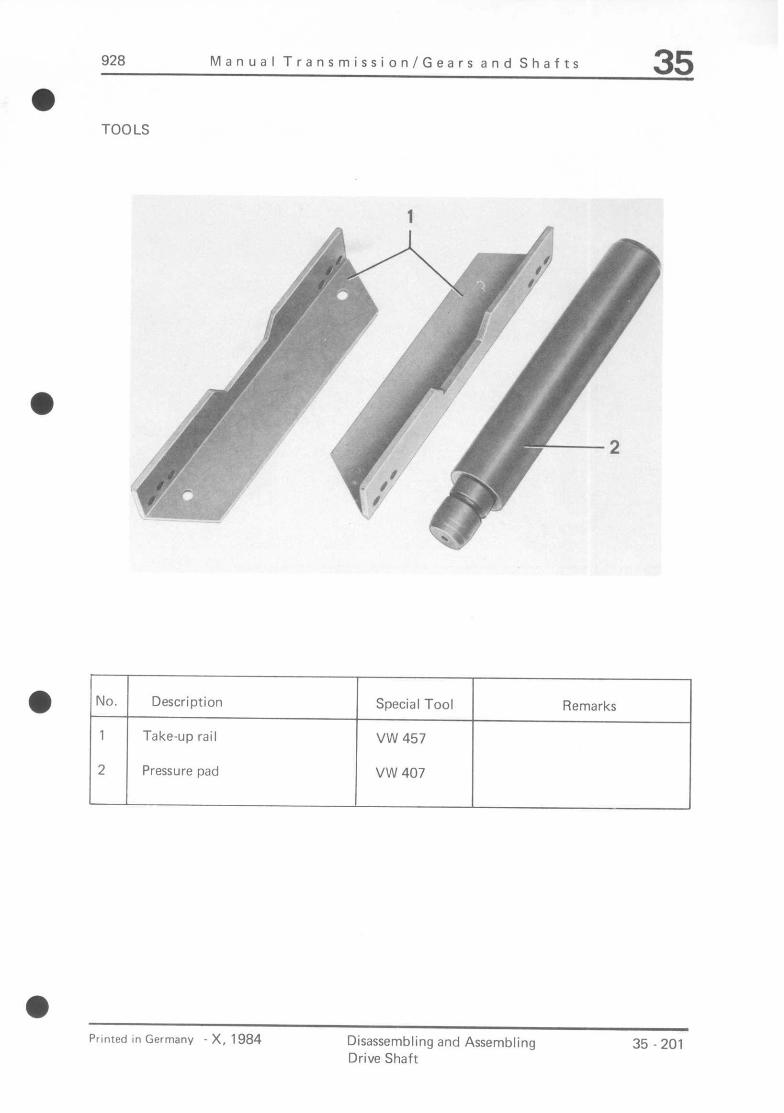
928 Manual Transmission/Gears and Shafts 35 a
TOOLS
@ No. Description
1 Take-up rail
2 Pressure pad
Special Tool
VW 457
VW 407
Remarks
Printed in Germany - X, 1984 Disassembling and Assembling Drive Shaft
35 - 201

35 Manual Transmission/Gears and Shafts 928
DISASSEMBLING AND ASSEMBLING DRIVE SHAFT -
4
1 \Y=y t \ - \\ --~ \, 111
r +w I --%a41 . L .sc .-.-. -.s.w.-.e.e . -.-
I 1’ l / d
I . /’ J
a 35 - 202 Disassembling and Assembling
Printed in Germany Drive Shaft

a
929 Manual Transmission I Gears and Shafts 35
No. Description
1 Needle
2 Thrust ring
3 Synchronizing ring
4 Circlip
5 Grooved ball bearing
6 Drive shaft
Note when:
City. Removing Installing
2 Install with bearing greas
1
1 Mark for reassembly Mount with same gear.
Check for wear
1
1 Press off with VW 457 Heat to approx. 100’ and VW 407 C/21 2’ F and drive on
1
Note
As of MY ‘92, a modified drive shaft with new needle cages and axial retainer is used.
A = Snap Ring
B = Thrust washer
a Dlsassembllng and assembling drive shaft 35 - 203
Printed in Germany - XXXI, 1993

35 Manual Transmission/Gears and Shafts 928
a
DISASSEMBLING AND ASSEMBLING DRIVE SHAFT
Disassembling
1. Remove circlip.
2. Press off grooved ball bearing with a pertinent pressure pad and Special VW 457.
,!Lm.+n, -@J:
/ !
ebA+pJp!nm- p?L7 -..I 6
hi-we. w
Assembling
1. Heat grooved ball bearing to approx. 100° C / 212’ F and drive on.
2. Check synchronizing ring by pressing ring against taper of gear wheel and measure gap “a” with a feeler gage blade.
Installed distance (new) = 0.9 to 1.5 mm Wear limit = 0.6 to 0.7 mm
a
35 - 204 Disassembling and Assembling Drive Shaft
Printed in Germany

928 Manual Transmission/Gears and Shafts 35 m
TOOLS
2 ,.. -. - . ,,P .- ,,I /, ”
,I’ /
CF. f? -p ,-
? i .i
_.- .-- ‘. /
a i ,’ c* i‘
I1 g
i 1’ \
A 3
;’ ‘%
3
/O --q
1”’ 4 i-
VO. Description
1 Holder
2 Wrench socket
3 Holding rail
4 Separator
Special Tool
9219
9218
VW 457
Remarks
Standard
a
Printed in Germany _ X, ,984 Disassembling and Assembling Drive Pinion
35 -205

35 Manual Transmission/Gears and Shafts 928
DISASSEMBLING AND ASSEMBLING DRIVE PINION
44 43 42 41 40 39 38 37 36 35
a 28 27 26 25 24 232Z? :
.-.-.C.- eC.C.L. -.-.---
r i .-Fii 1 p\,,
“:‘J,, \
q&$ , ‘:$ b$F i
je$$;g$ “,
I 1 I 7621
a
a
35 -206 Disassembling and Assembling Printed in Germany
Drive Pinion

928 Manual Transmission/Gears, Shafts 35
No.
1
2
6
a
9
10
l l1
12
13
14
Intercept stop
Compression spring
3uide sleeve
jynchromesh ring
1
I I
I
Description
Locknut
Actuating sleeve
Ball
Free gear, 4th gear
Needle cage
Inner race
Thrust washer ('85/'86 model = 6.0 mm) ('87 models = 10.5 mm)
Free gear, 3rd gear
Synchromesh ring
Needle bearing
RY.
7
1
3
3
3
1
1
1
1
1
1
1
1
1
i-
Removing Note W
Remove with Special Tool 9218 and 9219
Remove together with guide sleeve and synchromesh parts
Mark for reinstallation
Mark for reinstallation
Mark for reinstallation
Mark for reinstallation
Mark for reinstallation
a
'n: Installing
Tightenin (221 ftlb 3
torque 300 Nm and lock by
punching collar
Insert right way round
Check for wear, reinstall with original gear
Reinstall with original gear
Heat to approx. 100°C, install with original gear
Check for wear, install with original gear
Install with original gear
Printed in Germany - XVI,1987 Disassembling and Assembling 35 - 207 Drive Pinion

35 Manual Transmission/Gears, Shafts 928
No.
15
Description
Inner race
16
17
18
19
Ball
20
21
Intercept stop
Compression spring
Guide sleeve
22
Synchromesh ring
Free gear, 2nd gear
23 Needle cage
24 Inner race
25 Thrust washer ( ‘85/‘86 model z = 6 mm) ('87 models = 2.5 mm)
26 Free gear, 1st gear
27 Synchromesh ring
I
ty.
1
1
3
3
3
1
1
1
1
1
1
1
1
Note When: Removing
Mark for reinstallation
Installing
Heat to approx. lOO”C, install with original gear
Remove together with guide sleeve and synchromesh parts
Insert right way round
Mark for reinstallation Check for wear, install with original gear
Mark for reinstallation Install with original gear
Mark for reinstallation Heat to approx. lOD"C, install with original gear
Mark for reinstallation Check for wear, install with original gear
35 - 208 Disassembling and Assembling Drive Pinion Printed in Germany

928 Manual Transmission/Gears, Shafts 35
No.
28
29
30
l ::
33
34
35
36
l 37
38 Inner race
39
40
41
Description
Needle cage
Inner race
Operating sleeve
Ball
Intercept stop
Compression spring
Guide sleeve
Synchromesh ring
Free gear III, reverse gear
Needle bearing
Shim
Taper'roller Searing inner race
Spacer
Qty.
1
1
1
3
3
3
1
1
1
1
1
1
1
1
Note When: ?emoving
4ark for reinstallation
lark for reinstallation
Remove together with guide sleeve and jynchromesh parts
lark for reinstallation
lark for reinstallation
lark for reinstallation
lark for reinstallation
'ress off together with learing cover
Installing
Install with original gear
Heat to approx. lOO”C, install with original gear
'87 models onward, with recess (see page 35 - 213 for installation position)
Insert right way round
Check for wear, insta with original gear ('87 models onward, with modification to tips of teeth, brown for identification).
11
Install with original gear
Re-measure if necessary, heat to approx. 1OO'C (see page 39 - 216)
Calculate thickness if necessary
Heat to approx. 100°C
Printed in Germany - XVI,1987 Disassembling and Assembling 35 - 209 Drive Pinion
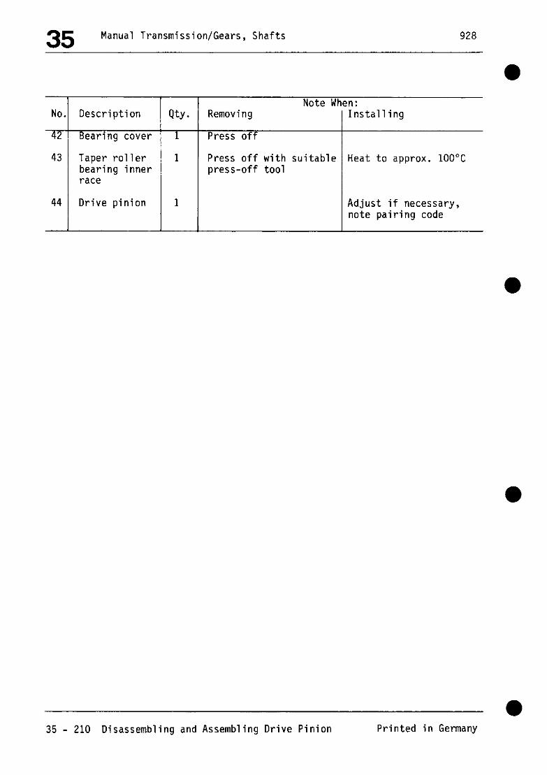
35 Manual Transmission/Gears, Shafts 928
Qty.
1
1
Removing Note When:
Installing
Press off I
Press off with suitable Heat to approx. 100°C press-off tool
Adjust if necessary, note pairing code
l
35 - 210 Disassembling and Assembling Drive Pinion Printed in Germany

928 Manual Transmission/Gears and Shafts 35 a
DIASSEMBLING AND ASSEMBLING DRIVE PINION
Disassembling
1. Remove lock nut for drive pinion with Special Tools 9219 and 9218.
2. Press off gear wheels with Special Tool VW 457 and a pertinent support.
$?F;
- _-.-,,
L ., I..
; -.“.L~.‘;.. (
-FL-
A = Standard U-iron (U 200) approx. 260 mm long.
3. Press off bearing cap with a pertinent pressure pad.
Printed in Germanv X. 1984 Diassembling and Assembling Drive Pinion
35 - 211

35 Manual Transmission/Gears and Shafts 928
4. Press off large taper roller bearing inner race with a pertinent separator.
2. Mount bearing assembly on drive pinion and apply initial pressure of 20 kN (2 tons).
3. Mount drives for synchronization in correct position (domed side facing sliding sleeve).
4. Check synchronizing rings by pressing rings against tapers of gear wheels and measuring gaps “A” with a feeler gage blade.
Assembling
Note Installed distance (new) = 0.9 to 1.5 mm Wear limit = 0.6 to 0.7 mm
If drive pinion has to be adjusted, it must only be assembled after completion of adjustments (see “Adjusting Drive Pinion” on page 39 - 215).
1. Inner races of needle bearings as well as bearing surfaces on guiding sleeves and thrust washers must be cleaned of oil.
Lubricate needle cages, bores and bearing surfaces on both sides of gear wheels with oil thoroughly.
35 - 212 Diassembling and Assembling Printed in Germany
Drive Pinion

928 Manual Transmission/Gears, Shafts 35
5.Apply approx. 60 kN (6t) to press assembled drive pinion into position over hub of guide sleeve.
:-- ,
i +. & ;2
?“ -‘- ‘.. ., h .liiT:.,lil -w.1/_-
~. “‘.+e+r. ,
6.Tighten locknut to 300 Nm (221 ftlb) and lock by punching collar.
--_. ‘1 i _ ----.(
wry: * &@& . . . ..~q
‘, J fi;1” L\ / ; ‘_‘,‘, 1 j T
. ..>..i\ . _. ,i
d.J$:I- _ ‘;y (( ;i ;- : .;;? ,\
* -.?Nf’ -’ j <‘- ’ *I, *I
i
i:! :d
‘h* 4
Modification, '87 models onward
The tips of the teeth of the 1st and reverse-gear operating sleeve have been modified. Note installation position, the recess (arrowed) must face the reverse free gear.
1 = Free gear, reverse gear 2 = Free gear, 1st gear 3 = Operating sleeve lst/reverse
gear
Printed in Germany - XVI,1987 Disassembly and Assembly 35 - 213 Drive Pinion

928 Manual Transmission/Gears and Shafts 35
a TOOLS
/ -
b
Remarks

35 Manual Transmission/Gears and Shafts 928
DISASSEMBLING AND ASSEMBLING COUNTERSHAFT
Jr+-. ---\
li-zi
P-w ,~ - f ‘)---Ta.~ :\\ 1 _
q gg, +%>’ ~ \a;, ‘;r”Z
Y?-- ~Lp.~-
r
9
35-216 Disassembling and Assembling Countershaft Printed in Germany
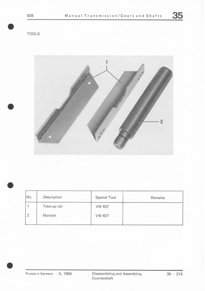
928 Manual Transmission/Gears and Shafts 35 0
TOOLS
No. Description Special Tool Remarks
1 Take-up rail VW 457
2 Mandrel VW 407
Printed in Germany - X, 1984 Disassembling and Assembling 35 - 215 Countershaft

35 Manual Transmission/Gears and Shafts 928
DISASSEMBLING AND ASSEMBLING COUNTERSHAFT
1
- !y- , -
wa -- 9s
, ,* '$G
. --..-I ~.2-"c-"
a 'A~\-"-
4 5 6
35 -216 Disassembling and Assembling Countershaft Printed in Germany

928 Manual Transmission/Gears and Shafts 35 0
30. 1 Description
Printed in Germany X, 1984 Disassembling and Assembling Countershaft
35-217

35 Manual Transmission/Gears and Shafts 928
DISASSEMBLING AND ASSEMBLING COUNTERSHAFT
Disassembling
1. Remove circlip.
2. Press off gear wheels with a suitable mandrel and Special Tool VW 457.
rnLE-m .-r ? 7- - -
Assembling
Heat gear wheels to approx. 100° C / 212O F and install to correct position
35-218 Disassembling and Assembling Printed in Germanv
Countershaft

928 Manual Transmission/Gears, Shafts 35 a
DISASSEMBLING AND ASSEMBLING LAYSHAFT (87 MODELS ONWARD)
I. . . .
7
:@q$$ f3 -z?- ,,a ‘y*
‘1.
8
Printed in Germany - XVI, 1987 Disassembling and Assemblin 3
35 - 219 Layshaft ('87 Models Onward

35 Manual Transmission/Gears, Shafts 928
No
-
1
Description
Needle cage
2 Circlip
3 Needle bearing
4 Circlip
5 Fixed gear
6 Spacer
7 Fixed gear, 4th gear
8 Fixed gear, 3rd gear
9 Layshaft
Note When: Removing
Press off with VW 407 and VW 457
Press of with VW 407 and VW 457
Press of VW 407 and VW 457
Installing
Always replace as a pair, collar toward a
spacer
Rlways replace as a pair, collar toward spacer
Always replace as a pair, collar toward stop
35 - 220 Disassembling and Assemblin Layshaft ('87 Models Onward 3
Printed in Germany

928 DifferentiaI/Transaxle System 39 l
TOOLS
NO. Description Special Tool Remarks
1 Pressure pad 9147
2 Rod From P 254
a Printed in Germany - X, 1984 Removing and Installing Differential 39 - 201
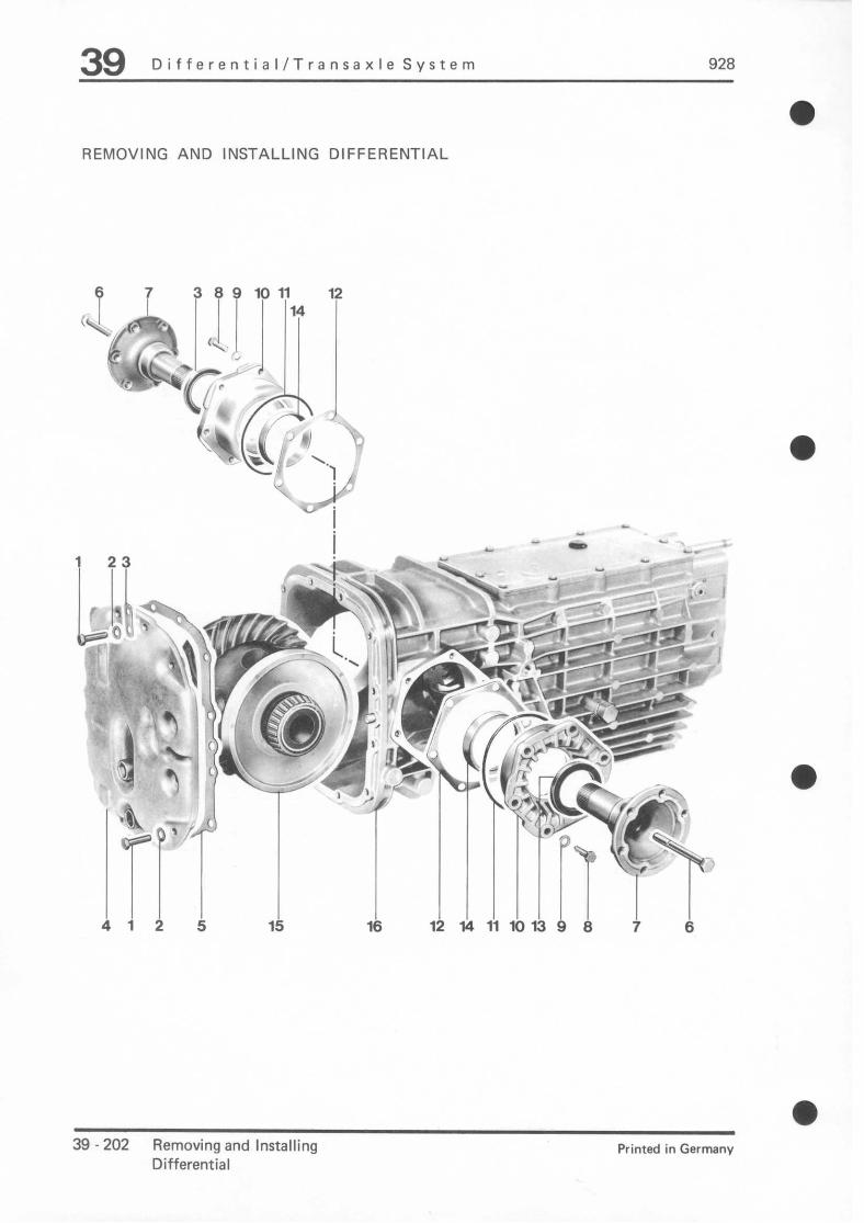
39 Dlfferential/Transaxle System 928
REMOVING AND INSTALLING DIFFERENTIAL
.7 i 7 7 7 ‘P ‘L4 ‘f cyf-t 1 (L.1, / 1 1 1 * , F-’
-. : I u-0 CI - :. -zz;- , <:- -I- ’ A
. - . . . . . - 1398 7 a
39 - 202 Removing and Installing Printed in Germany
Differential

928 Differential/Transa.xle System 39 a
No. Description Note When: Special
Qty. Removing Installing Instructions
1 Bolt 12 Torque: 22 Nm (16 ftlb)
2 Washer 12
3 Holder 1
4 Case cover 1
5 Gasket 1 Replace
6 Bolt 2 Torque: 43 Nm (31 ftlb)
7 Joint flange 2
8 Bolt 12 Torque: 22 Nm (16 ftlb)
9 Washer 12
10 Bearing cap 2 Mark for Must be installed reassembly on same side
11 O-ring 2 Replace, coat with transmission oil
12 Shim X Note number and Determine again, thickness on if necessary each side for reassembly
Printed in Germany - X, 1964 Removing and Installing Differential 39 - 203
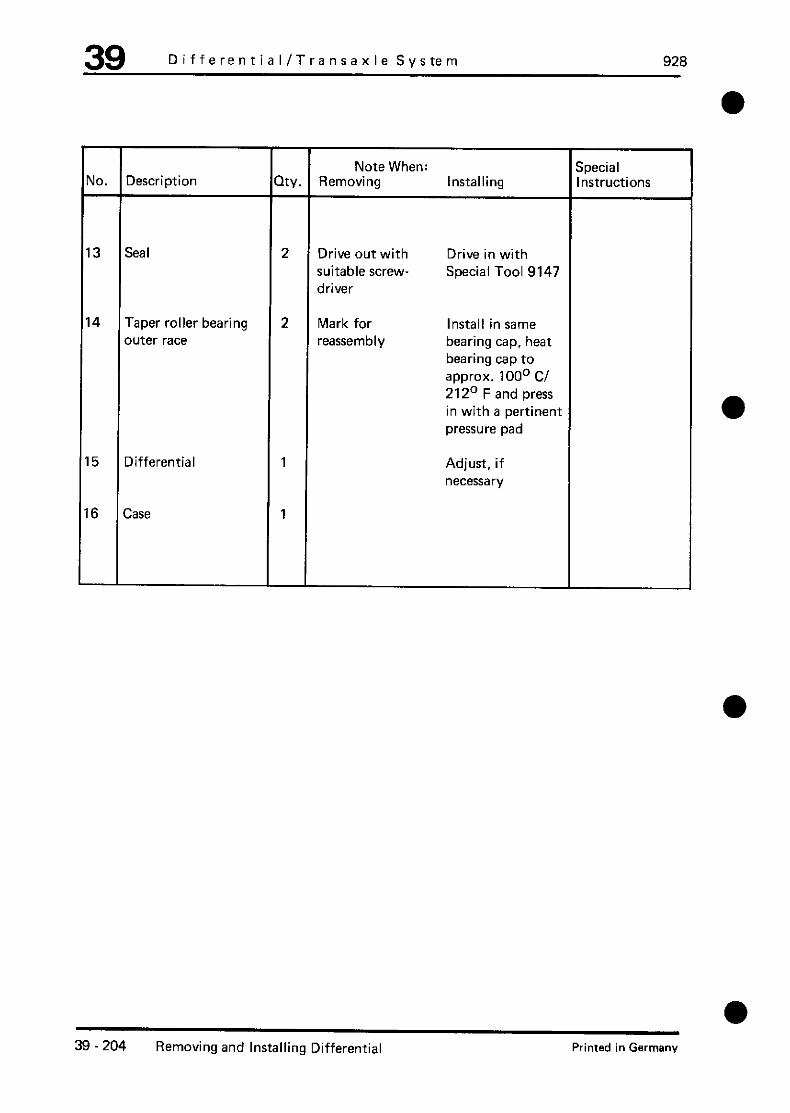
39 DifferentiaI/Transaxle System 928
Vo. Description Note When: Special
Qty. Removing Installing Instructions
I3 Seal 2 Drive out with Drive in with suitable screw- Special Tool 9147 driver
I4 Taper roller bearing 2 Mark for Install in same
outer race reassembly bearing cap, heat bearing cap to approx. 100° Cl 212’ F and press in with a pertinent pressure pad
I5 Differential 1 Adjust, if necessary
16 Case 1
39 - 204 Removing and Installing Differential Printed in Germany

928 DifferentiaI/Transaxle System 39
REMOVING AND INSTALLING DIFFERENTIAL
Removing Note
1. Drain transmission oil.
2. Unscrew joint flange bolt and remove joint flange.
Preload of the taper roller bearings could cause tension on the case when tightening bolts for the side case covers, which later could impair installation of the rear case cover. Consequently the rear case cover should be installed before tightening the bolts.
Installing
Drive in joint flange seal with Special Tool 9147.
a Printed in Germany - X, 1984 Removing and Installing
Differential 39 - 205

928 Differenttal. Traneaxle Svstem 39
Measuring the plate wear on the proportional-slip differential
The wear dimension can be determined only
by means of the measuring cylinder - special
tool 9514.
1. Remove output cylinder.
In order to avoid venting of the differential sys-
tem, the pressure line at the output cylinder
must not be disconnected when the gearbox
is installed. In this case, unflange the output cylinder with pressure line from the housing.
2. Back off the adjustlng screw of the measur- ing cylinder as far as possible (facilitates as- sembly of the cylinder).
3. Mount the measuring cylinder on the gear- box and tighten the knurled nut.
Note
If the gearbox is installed, it is recommended to use two studs M 8 x 45 wfth continuous
thread to secure the measuring cylinder.
4. Screw in the adjusting screw at the maasur-
ing cylinder until there is no longer any axial play at the spacer tappet. Read off the wear
dimension In this position.
New dimension = 34.5 mm Wear dimension = 45.0 mm
357.39
LS = Measuring range for longitudinal lock
911 Carrera 4
QS = Measuring range for transverse lock 928 S 4, 928 GT and 911 Carrera 4
1 - Spacer tappet
2 -Adjusting screw 2a - Measuring groove on adjusting screw
3 -Knurled nut
Note
When the wear dimension has been reached,
the plates of the lock must be replaced. Do
not correct the wear dimension at the thrust bearing under any circumstances.
l Measuring the plate wear on the proportional-slip differential 39 - 206a
Printed in Germany - XXN, 1989

928 Differential, Tranaaxle System 39
Removing and installing the proportional-slip differential
Tool
l Z Zaswing cylinder
Sonderwerkzeug Bestellnummer Erhterung
9147 000.721.914.70
from P254
9514 000.721.951.40 -
a
Removing and installing the proportional-slip differential 39 - 206c Printed in Germany - XXIV, 1989

Differential, Transaxle System 929
Removing and installing the proportional-slip dlfferentlal
39 - 2066 Removing and installing the proportional-slip differential Printed in Germany - XXN, 1989
a

a
928 Differentiil. Tranaaxle Svatem 39
No.
iexagon screw
Masher
qetaining plate
iousing cover
SeaI
iexagon screw
7 F Texible flange
a t iexagon screw
9 v Vasher
IO F letaining plate
I1 F letaining plate
I2 E Searing cap
13 ( I-ring
14 s Shim
15 Sealing ring
16 ‘aper roller bearing outer
aceway
17
I6
F ‘orsche limited-slip differ-
f mtial
E Ingaging lever
3Y.
12
12
1
1
1
2
2
12
12
1
1
2
2
X
2
2
1
1
T Note when
3lock flexible flange with
suitable mandrel
dentify for red-installation
Uote number and thick-
less for re-installation per
side
Renew, coat with gear
Determine anew if net
=v
Irive out with a suitable Drive in with special tc icrewdrtver 9147
Hark for re-installation Install in the same bei ing cap, heat bearing
cap up to approx. 100 “C and press in with SI
table thrust piece.
f
nstalling
Tighten with 22 Nm
Renew
Tighten with 43 Nm
Tighten with 22 Nm
Must be fitted on the
same side
oi
:es
)Ol
tr-
ui-
Readjust if necessary
Fii in the correct posit ion
1
a Removing and installing the proportional-slip difkrentiil 39 - 206e Printed in Germany - XXN, 1989

39 Dlfferantlal,TransaxlaSyatem 928
No. Description
19 Thrust bearing
Note when: Oty. Removing Installing
1 Onty adjust or remove if Readjust ff necessary. the plates of the lock are Screw in with Loctite removed or determine in- 222 and lock with hexa- stallation position for re-in- gon nut stallation
20 Hexagon nut 1 Tighten with 85 Nm
21 Sealing ring* 1 Renew
22 Bellows 1 Oil slightly and press in home with a suitable pipe piece (e.g VW 41Sa)
23 Gearbox 1
l Deleted as of MY ‘92. Sealing is done with Loctite 222.
39 - 206f Removing and InstallIng the proportlonal-sllp dlfferentlal l Printed in Germany-XXXI, 1993

Differential, Transaxle System
Assembly instructions for removal and installation
Note Note
Before the limited-slip differential is removed,
determine the wear condition of the plates
under all circumstances (refer to Page 39- 206a).
If the worn plates are reused, the thrust bear- ing (No. 19) must not be adjusted. If adjust- ment or removal of the thrust bearlng should
be necesssary (e.g. in the event of leaks), measure the Installation position of the thrust bearing for re-installation under all circum- stances.
Always renew the output cylinder as well if the bellows (No. 22) leaks.
1. Adjusting the thrust bearing: (required only tf the plates were renewed)
- The locking torque and driie set must be
adjusted.
- The bellows (No. 22) must be installed Screw in the thrust bearing by only a few
turns. Pay attention to the installation position of
the engaging fork.
- Back off the adjusting screw of the measur- ing cylinder as far as possible (facilitates as-
sembly of the cylinder).
Removing and installing the proportional-slip differential Printed in Germany - XXN, 1989
39 - 2069

Differential, Tranaaxle System 928
- Fit the measuring cylinder special tool 9514 - on the gear and tighten the knurled nut.
- Set a setting dimension of 34.5 mm (in the
transverse lock measuring range) with the adjusting screw on the measuring cylinder.
LS = Measuring range for longitudinal lock
911 Carrera 4
QS = Measuring range for tranverse lock
928 S 4, 926 GT and 911 Carrera 4
1 Spacer tappet 2 - Adjusting screw
2a Measuring groove on adjusting screw
3 - Knurled nut 4 - Thurst bearing
5 - Hexagon nut
6 - Sealing ring
- Screw in the thrust bearing until there is no longer any axial play at the spacer tappet
of the measuring cylinder. Lock the thrust bearing with the hexagon nut in this posi- tion (tightening torque 65 Nm)
39 - 206h Removing and installing the proportional-slip differential Printed in Germany - Mlv. 1989

928 Differential, Transaxle System 39
Bleeding hydraulics of Porsche controlled slip differential (PSD)
. Remove rear Ml inner fender
l Connect bleeding device to PSD hydraulic reservoir
. Disconnect vent line
l Build up bleed pressure (approx. 1.5 2.0 bar)
1. Bleeding the pressure reservoir
To charge the pressure reservoir, the ignition must be switched on. When the pressure reservoir has been charged, the pump cuts out; reservoir pressure is then ap-
prox. 180 bar.
l Connecting the bleed cylinder.
. Switch off the ignition.
. Carefully open the bleed connection and allow the pressure level to drop gradually. While this is being done, the ignition must remain switched off, to ensure that pressure is completely reduced and air expelled from the reservoir.
. Repeat this procedure several times, making sure that the ignition is switched on or off a1 the appropriate stages in the procedure.
2. Bleeding the valve block and the locking line to the lock slave cylinder
.
.
.
l : . . . . . . .
Connect the 9288 system tester
Switch the ignition “ON”
Connect the bleed cylinder to the bleed screw on the slave cylinder
Open the bleed screw on the slave cylinder
Select “Start PSD Bleeding” and actuate repeatedly until no further air emerges
The bleeding device must remain switched on, because the reservoir volume is used up rapidly,
After this, close the bleed screw on the slave cylinder
Select “Stop Bleeding” and “Start Pressure Reduction” at the system tester
Switch off the bleeding device and disconnect it
Screw on the reservoir cover
Open the vent line at the reservoir again
Check level in reservoir. The liquid must be approx. 1 cm above the step in the reservoir body
(with the pressure reservoir charged)
a Bleeding hydraulics of Porsche controlled slip differential (PSD) 39 - 206i Printed in Germany - XXV, 1990

DifferentiaI/TransaxIe Svstem 32
a TOOLS
2 $
f-$ ,/- . ..--- ----- . L. \.._ I /
a
3- ? 1 ~‘2,’ ~ .,‘. I i 1
- b-q a ,_’
) .*
: ; p-- -1
No. Description Special Tool Remarks
1 Pressure pad P 263
2 Extractor Standard
3 Pressure pad P 264 b
a Printed in Germany - X. 1984 Disassembling and Assembling 38 - 207
Differential

39 Differential I Transaxle System 928
a DISASSEMBLING AND ASSEMBLING DIFFERENTIAL
1 15 '1 '1 8 14 8 3
9% / 1:
12 13 lb1113 12
Y‘i i"
L: / 3 sti ->
a 39 - 208 Disassembling and Assembling Printed in Germany
Differential
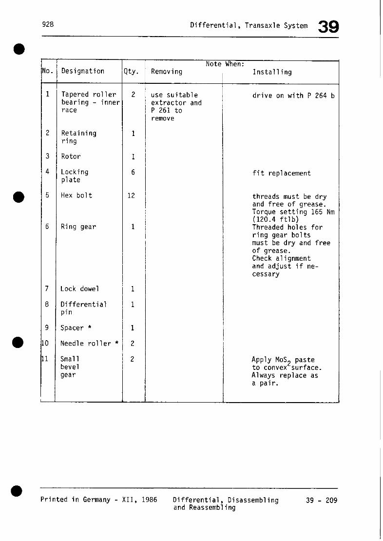
928 Differential, Transaxle System 39
No.
1
2
3
4
5
6
7
8
9
10
11
L
Designation
Tapered roller bearing - inner race
Retaining ring
Rotor
Locking plate
Hex bolt
Ring gear
Lock dowel
Differential pin
Spacer *
Needle roller *
Small bevel gear
ty. -
2
1
1
6
12
1
1
1
1
2
2
-
T Note When: Removing
use suitable extractor and P 261 to remove
Installing
drive on with P 264 b
fit replacement
threads must be dry and free of arease. Torque setting 165 Nm (120.4 ftlb) Threaded holes for ring gear bolts must be dry and free of grease. Check alignment and adjust if ne- cessary
Apply MoS2 paste to convex surface. Always replace as a pair.
1
Printed in Germany - XII, 1986 Differential, Disassembling 39 - 209 and Reassembling

39 Differential, Transaxle System 928
15
Designation
Large bevel gear
Threaded rod
Dowel pin
Differential housing
Qty. Note when:
Removing Installing
Apply MoS vex surfa e. ?
to con- Only
replace as a pair.
*Needle bearing changed from 86 models onward. The new needle bearings mean that the spacer need no longer be fitted. The new needle bearings are not interchangeable with the earlier version.
39 - 210 Differential, Disassembling and XII, 1986 Printed in Germany Reassembling

928 DifferentiaI/Transaxle System 39
DIASSEMBLING AND ASSEMBLING DIFFERENTIAL
Diassembling
1. Pull off taper roller bearing inner race
P 263.
2. Coat oval surface of differential gears ._, I mMm2 paste.
3. Install large differential gears with press-fit threaded plates through large opening in differential case and hold with joint flanges.
‘4. Lr:s pm,- - ;;, e. -
--..A.Ed- ‘k:,
“1 .?:
m
Assembling
1. Place ring gear on case and tighten ring gear bolts to torque of 165 Nm (119 ftlb). Slide lockplate into groove of bolts, squeeze together at front with a pliers (to unite lockplate with bolt) and bend down over a hexagon surface to lock.
Printed in Germany - X. 1984 Disassembling and Assembling Differential
39-211

39 DifferentiaI/TransaxIe System 928
a
4. Install small differential gears between large differential gears and turn, until bores of gears are aligned with bores in case.
6. Drive in differential shaft in correct position and lock with pin.
- ._I
F -.r;- “1 A.
&i------ :.i
s#qQ b3& r-. y+y.pj.y” f ; I\;* ’ ,, /’ I I,: ; ’ ,.I :i .
&--- -_- -- sl&mw:;~2
5. Install needle cages and spacer.
--
,-_ _I, “i h WA’ --7$ If- -‘Y b ,, 1’ -4 I,” e /,j $1 7 , :x t - xx *e, .- ;..\,1. 3 ./+.< 9. US * s/ +, --y _ -- _
l ‘_*
.--ax -2
7. Drive on taper roller bearing inner race with P 254 b.
39 -212 Disassembling and Assembling Printed in Germany
Differential

928 Differential, Transaxle System 39 '
l TOOL
* 130 t
t s --.
+
No. Designation Special tool Remarks
1 Connector --- Improvised tool The connector for the flexible flange may be fabricated from a 6 x 18 piece of flat steel.
l Printed in Germany - XII, 1986 Limited-Slip Differential, 39 - 212a
Disassembling and Assembling (40% Lock-up)

39 Differential, Transaxle System 928
DISASSEMBLING AND REASSEMBLING LIMITED-SLIP DIFFERENTIAL 0
6 7
9’ / r Y$fi;, . I
r .-.- .-.- .-. -.-.-. J .
i lo-$y~ 1;1 ? 1p ty
i *m - -‘#p?, P “=az..- -- I 1-1 1 gi& 1
c 1 I ’ I-= I x4.*
r .-.- .-.-.-.-.- .-. .
a
m 39 - 212 b Limited-Slip Differential (40% Lock-up)
- Printed in Germany
Disassembling and Reassembling

a
a
a
928 Differential, Transaxle System 39
No. Designation KY. removing
1 Flat-head screw
2 Housing cover
3 Take-up disk
4 Disk spring
5 Outer plate
6 Inner plate (molybedenum coating)
7 Pressure ring
8
9
10
11
12
Axial bevel gear
Screw disk
Bevel pinion
Differential axle
Differential housing
2
1
2
2
2
2
2
2
2
4
2
1
Note when
ush out of axial install in cor- eve1 gear corect oosition
Installing
torque down to 10 Nm (7.3 ftlb)
install in correct position
install right way round
a Printed in Germany - XII, 1986 Limited-Slip Differential 39 - 212 c
(40% Lock-up) Disassembling and Reassembling

39 Differential, Transaxle System 928
DISASSEMBLING AND REASSEMBLING LIMITED-SLIP DIFFERENTIAL (40% LOCK-UP)
Disassembling
l.Unscrew flat-head screw from housing cover and remove cover.
*, 7 f- __, c_ ‘I‘-AP :4?
2.Remove all internals.
Reassembly
l.Check all parts for wear or damage and replace as neces- sary.
a)Differential housing: Check guide grooves for outer plates and pressure rings for wear.
b)Pressure rings: Check for signs of heavy wear or ridging on the guide dogs and con- tact surfaces. The rings must move easily in the differential housing.
c)Axle bevel gears: The contact surfaces for the take- up plates should not be worn and the inner plates must move easily on the splines.
d)Plates: Check inner and outer plates for wear. There should be no signs of excessive wear on the guide dogs of the outer plates or the teeth of the inner plates.
2.Apply transmission oil to all slide faces of plates, pressure rings and differential axles prior to re- assembly.
3.Insert take-up disks so that the dog engages the hole in the housing or cover. As an aid to assembly, apply enough grease to the disks to hold them in place.
a 39 - 212 d Limited-Slip Differential (40% Lock-up)
Disassembling and Reassembling Printed in Germany

a
928 Differential, Transaxle System 39
4.Install remaining components as shown in the exploded drawing.
Note
The disk springs must be installed with the convex side pointing in to- ward the plate package.
r--1/////1 Imti
1. .Use a depth gage to measure depth of housing "a". Example: a = 110.80 mm
2.Measure the cover at "b". Example: b = 29.20 tmn
1 - Disk spring
2 - Outer plate
3 - Inner plate
4 - Take-up disk
Reestablishing the thickness of the plate package; if new parts have been installed, the thickness of the plate package must be reestablished.
J.Calculate clearance "c" inside housing. c = a - b
Example:
a = 110.80 m-n b = 29.20 mm
a Printed in Germany - XII, 1986 Limited-Slip Differential 39 - 212 e
(40% Lock-up) Disassembling and Reassembling

39 Differential, Transaxle System 928
4.To measure the thickness "d" of the plate package (with 2.0 mm thick outer plates, but without disk springs), hold the plate pack- age lightly in a vise and measure "d" with a micrometer.
Example: d = 76.40 mm.
I ~14 pill+--T-c----.--
--dL- ‘I:-ji- \I, L ‘w’ ‘-‘1
I
5.To determine "e" (must be equal to 5.20 mm) e = c - d
Example:
c = 81.60 mm d = 76.40 mm
e = 5.20 mm
a
e2 + e2 = e = 5.2 mm
Note
If "e" is greater than or less than specified, install thicker or thinner outer plates.
"e" less than 5.20 mm - install thinner plates
"e" greater than 5.20 mn - install thicker plates
-------- --------
Outer plates of thicknesses 1.9 mn, 2.0 mn and 2.1 mm are available.
6.After assembly, measure the slip torque with drive applied to one axial bevel gear and the other fixed. Clamp a flange with two screws in the vise and place dif- ferential in position. Locate second flange with improvised connector and turn differential with a torque wrench. A torque of 10 . ..35 Nm (7.3... 25 ftlb) must be attained.
39 - 212 f Limited-Slip Differential (40% Lock-up) Printed in Germany Disassembling and Reassembling

a
928 Differential, Transaxle System 39
A = Connector (improvised)
Note
If the specified torque is not at- tained with the thickest outer plates, all the plates are worn and require replacement.
Printed in Germany - XII, 1986 Limited-Slip Differential (40% Lock-up) Disassembling and Rea~~emb:f~gg

928 Differential, Transaxle System 39
Dismantling and assembling the proportional-slip differential
Tool
2
r-n
l No. 1 Description ~~~’ Special Tools Order Number Remarks
“,” - 105 ~..~_,
Sickle spanner
Thrust piece
Thrust piece
Measuring fixture
Connection piece
P263
P264b
9508/i
000.721.263.00
000.721.264.20
000.721.950.81
commercially available
2 parts
Self-manufacture (flat
steel 10 x 20)
a Dismantling and assembling the proportional-slip differential 39 - 212i Printed in Germany - WV. 1989

928
Dismantling and assembling the proportional-slip differential
39 - 212j Dismantling and assembling the proportional-slip differential a
Printed in Germany - XXN, 1989
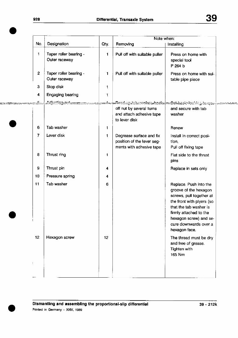
92s Differential. Transaxle Svstem 39
NO.
1
2
3
4
6
7
6
9
IO
I1
12
Designation
Taper roller bearing Outer raceway
Taper roller bearing -
Outer raceway
Stop disk
Engaging bearing
Tab washer
Lever disk
Thrust ring 1
Thrust pin 4
Pressure spring 4
Tab washer 6
Hexagon screw 12
City.
1
T Note when: Removina
Pull off with suitable pullet
1 Pull off with suitable pullet
1
1
. ~-~~*~~, rasT~4-:~:- ~-c~:ltlL~~- L-J illume ::%&r*~qex ;iii;<::e~ ~*:_;
off nut by several turns
and attach adhesive tape to lever disk
Degrease surface and fix
position of the fever seg-
ments with adhesive tape
I nstalling
Press on home with
special toot
P264b
Press on home with sui- table pipe piece
~~~cYe* c __ : _~ I~_; II. &___.~
and secure with tab washer
Renew
Install in correct posi- tion,
Pull off fixing tape
Flat side to the thrust
pins
Replace in sets only
Replace. Push into the
groove of the hexagon screws, pull together at
the front with plyers (so that the tab washer is
firmly attached to the
hexagon screw) and se-
cure downwards over a hexagon face.
The thread must be dry and free of grease. Tighten with
165 Nm
Dismantling and assembling the proportional-slip differential Printed in Germany - XXIV, 1989
39 - 212k
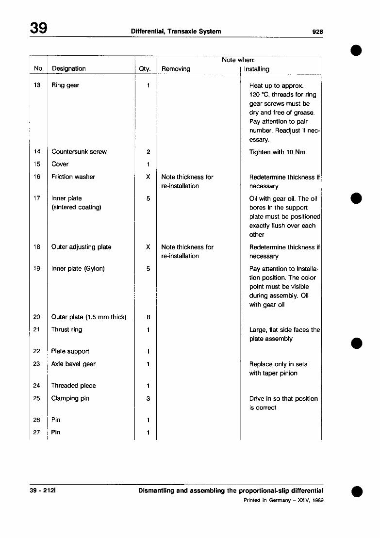
39 Differential, Transaxle System 928
No.
13
Designation -
Ring gear
14 Countersunk screw
15 Cover
16 Friction washer
17 Inner plate (sintered coating)
18 Outer adjusting plate
19 Inner plate (Gyfon)
20 Outer plate (1.5 mm thick)
21 Thrust ring
22 Plate support
23 Axle bevel gear
24 Threaded piece
25 Clamping pin
26
27
Pin
Pin
QtY.
1
2
1
X
5
X
5
8
1
1
1
1
3
1
1
r Note when: Removing nstalling
Note thickness for re-installation
Note thickness for re-installation
Heat up to approx. 120 “C, threads for ring
gear screws must be
dry and free of grease. Pay attention to pair
number. Readjust if net
essafy.
Tighten with 10 Nm
Redetermine thickness i necessary
Oil with gear oil. The oil bores In the support
plate must be positioner
exactly flush over each other
Redetermine thickness i
necessary
Pay attention to installa-
tion position. The color point must be visible
during assembly. Oil with gear oil
Large, flat side faces thr
plate assembly
Replace only in sets wfth taper pinion
Drive in so that position
is correct
39 - 2121 Dismantling and assembling the proportional-slip differential 0
Printed in Germany - XXIV. 1989

928
No. Designation
28 Pin
29 Cross-piece
30 Taper pinion
31 Axle bevel gear
32 Threaded piece
33 Friction washer
34 Housing
Note when:
QtY. Removing Installing
1
1
4 Replace only In sets with axle bevel gears
1 Replace only in sets with taper pinion
1
X Note thickness for Redetermine thickness i
re-installation necessary
1
a Dismantling and assembling the proportional-slip differential 39 - 212m PriMed in Germany - XXIV, 1989

Differential, Transaxle System 928
Assembly and dismantling instructions
Dismantling
Relieve the lever disk (No. 7) by undoing the
adjusting nut (No. 5). Degrease the lever disk and fix the segments for re-installation with adhesive tape.
A = Adhesive tape
Assembly
295-38
1. Determine the axial play of the axle bevel
gears and adjust to 0.05-0.15 mm by insert. ing the corresponding friction washers (No.
16/33).
Note
If parts (e.g. differential housing or bevel
gears) are replaced, the finished friction wash-
ers must be installed for measurement.
2. Drive in the clamping pins for the taper pin- ion shafts in the correct position,
ItA4
297.39
39 - 212n Dismantling and assembling the proportional-slip differential a
Printed in Germany - XXIV, 1989
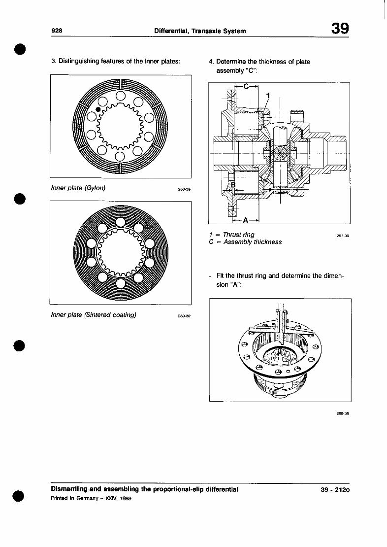
928 Differential, Transaxle System 39
3. Distinguishing features of the inner plates:
Inner plate (Gylon)
her plate (Sinrefed coating)
4. Determine the thickness of plate
assembly “c”:
= Thrust ring = Assembly thickness
- Fit the thrust ring and determine the dimen- sion “A”:
a Dismantling and assembling the proportional-slip differential 39 - 2120 Printed in Germany - XXIV, 1989

Differential, Transaxle System 929
- Determine the dimension “B”
- Determine the clear distance “c” (assembly thickness) in the housing.
Assemble the complete plate assembly in ac- cordance with the exploded drawing and measure wfth special tool 9508/l.
“c” = “A” _ “B” Example
A= 38.90 mm B= - 3.6Omm
C= 35.30 mm
Measurement result: 115.30 mm
Height of the special
tool* - 81.50 mm
Package thickness
* marked on toot
33.80 mm
- Adjust the thickness of the plate assembly to the calculated value “c” L? 0.1 mm by
means of the outer adjusting plate (No. 18).
5. Installation position of Gylon inner plates Fit Gyton inner plates so that the cdor point
is visible during assembly and so that the
spiral groove for the oil supply runs from in- side to outside in clockwise direction when
looking at the plate assembly (assembly direction) (refer to simplified diagram).
39 - 212p Dismantling and assembling the proportional-slip differential a Printed in Germany - XXIV, 198!3

929 Differential, Transaxle System 39
In addition, the oil bores in the supply plate of
the inner plates must lie exactly flush over each other. A missing tooth on the support
plate facilitates assembly.
A = Missing tooth
B = Spiral groove C = Oil bore D = Cdor point
6. Installation position of the lever disk.
L
7. Setting the basic locking torque
- Limited-slip differential completely as-
sembled (with engaging bearing and taper roller bearing inner raceways)
- Measure the cranking torque with one fixed and one driven axle bevel gear. For this pur-
pose, clamp one flange in the vice with two screws and measure the torque at the other
flange.
A = Connection piece
Dismantling and assembling the proportional-slip differential Printed In Germany - XXIV, 1989
39 - 212q

39 Differential, Tranaaxle System 928
- Adjust the cranking torque to 100 Nm by turning the adjusting nut with the sickle spanner. Then back off the adjusting nut to the locking groove at which the torque is
just below the cranking torque of 20 Nm.
Secure the adjusting nut with a tab washer.
A = Tab washer B = Adjosring nut
287.39
39 - 212r Dismantling and assembling the proportional-slip differential a
Printed in Germany - XXIV. 1989

926 Differential, Transaxle System 39
Dismantling and ass. controlled lim. slip differential with Valeo friction discs
Dismantling and ass. controlled lim. slip differential with Valeo friction discs Printed in Germany - XXXI. 1993
39 - 212s

39 Differential, Transaxle System 928
- 4 No. Designation
Thrust ring
Inner disc (Valeo)
Outer disc (1.5 mm)
Outer disc (Adjusting disc)
cny.
1
Removal
- Note:
1 Installation
Large, flat side faces disc pack
39 - 212t Dismantling and ass. controlled lim. slip differential with Valeo friction discs Printed in Germany - XXXI, 1993

928 Differential. Transaxle Svstem 39
a Dismantling and assembly notes
Note
Following fitting of the Valeo friction discs,
stacking and adjustment of the disc pack
have been modified.
1. Differences between the types of inner
discs used:
288-39
New Valeo inner disc
2. Determine thickness of disc pack
Pack thickness (new) = 35.2 - 0.2 mm Wear limit = 33.8 mm
Measure complete disc pack without thrust ring using Special Tool 9508/i.
Inner disc (Gylon)
Inner disc (sintered bellows)
Dismantling and assembling limited slip differential with Valeo friction discs Printed in Germany - XXXI, 1993
39 - 212u
39 Differential, Transaxle System 928
Example
Measurement result Special tool height*
Pack thickness
115.20 mm - 81.50 mm
33.70 mm
* Engraved on Special Tool
Note
If the wear dimension has been reached, all
inner discs must be replaced. To adjust the
discs to the specified pack thickness, use the
outer adjusting disc (No. 4).
3. Oil discs with transmission oil before fitting,
4. The oil bores in the carrier plate of the inner
disc must line up exactly.
39 - 212v Dismantling and assembling limited slip differential with Valeo friction discs Printed in Germany - XXXI, 1993

928 DifferentiaI/Transaxle System 39
TOOLS
,, 13 - ,_ -' - *'r -? -6
5’ t*Tcc
<;'"' 2 .'" ‘a
7 /;2 5.J li
,f)%
< eT4 Y
c:F
No. Description Special Tool Remarks
1 Universal gage VW 385/l 2 Centering discs VW 38514 3 Gage plunger VW 385/l 4 4 Dial extension gage 9150 5 Dial gage Standard, 3 mn
6 range
Gage plate VW 385/l 7 7 Master gage VW 385130 8 Feeler gage Standard, 0.05
to1 mm 9 Bushing 9145
10 Locking sleeve VW 52114 11 Adjustable lever VW 388 12 Gage plunger 9196 13 Gage bolt Standard 14 Dial holder gage VW 387 15 Pipe 9238 16 Dial gage Standard 17 Dial extension gage VW 0 382/l 18 Lever Local
manufacture
Printed in Germany - X, 1984 Adjusting Pinion and Ring Gear 39-213

928 Differential, Transaxle System 39
DETERMINING THICKNESS OF SHIM S5 ON DRIVE SHAFT
Note
The thickness of the shim determines the position of the idlers and reverse gear relevant to the housing and to the selector rods/selector forks.
Size "a" = Specified size determined by design factors (68.65 mm) Size "b" = Flange area bearing cover to end of drive-fit tapered roller
bearing Size "c" = Length of needle bearing - inner race
s3 = Shim S3
To calculate the thickness of the shim
S5 = 68.65 - b - c + S3
b, c and S3 are measured values
Printed in Germany - XII, 1986 Determining Thickness of Shim S5 39 - 215

39 Differential,TransaxleSystem 928
Measurlng Procedure:
1. Determine thickness of shim 53 (see page 39 - 221).
2. Apply 20 kN (21) to the bearing assembly,
pressing it on to drive shaft.
3. Measure%” (e.g. 44.20 mm)
Note
Shims from 2.20 mm to 3.30 mm are available in 0.1 mm graduations.
plll~r ’ “1
” -i ,~ff$~~~2& --%
d 8’. k I)
--.-i. em-+-- “ 4. Measure “c” (e.g. 22.18 mm).
5. Calculate Ss
S5 = 68.65 - b - c + S3
Ss = 68.65 - 44.20 - 22.18 + 0.45
Ss = 2.72
39 - 216 Determinlng thickness of shim 55 Printed in Germany - XXXI. 1993

928 DifferentiaI/Transaxle System 39 0
Note
For manufacturing reasons at the beginning of standard production transmissions of
Type G 28.10 from Transm. No. 11 F 00070 to 11 F 00451 and Type G 28.11 from Transm. No. 11 F 05069 to 11 F 05322
had been assembled with bearing assemblies, for which the following adjustment has to be made to determine the thickness of shim S5.
S5=112.00-b-c+S3-0.5
Old and new bearing assemblies differ as shown below.
Old Version New Version
a S5=112.00-b-c+S3-0.5 S5 = 112.00 - b c + S3
Printed in Germany X. 1984 Determining Thickness of Shim S5 39-217

39 DifferentiallTransaxle System 928
Recommended Sequence of Adjusting Drive Pinion and
Ring Gear
When it becomes necessary to adjust the drive pinion and ring gear, it would be in the interest of economical procedures to keep to the following sequence.
1. Determine the total shim thickness “Stot” (S1 plus S2) for the specified pre-load of the taper roller bearing/differential.
2. Determine shim thickness “S3”.
3. Determine shim thickness “SS”.
4. Divide total shim thickness “Stot” in SJ and S2 so that there is the specified amount of backlash between the ring gear and drive pinion.
The goal of adjustments is to relocate the point of optimal quiet running as was determined in the special testing machine during production.
Perfect results require absolute care and cleanliness during all assembly measuring operations.
Location of Shims
SJ = Shim for ring gear S2 = Shim for ring gear
S3 = Shim for ring gear SS = Shim for pinion/ring gear
39 - 218 Adjusting Drive Pinion and Ring Gear
Printed in Germany
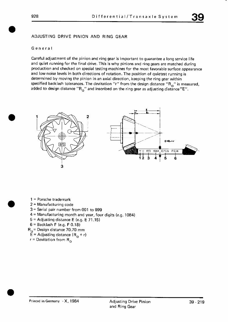
928 DifferentiaI/Transaxle System 39
ADJUSTING DRIVE PINION AND RING GEAR
General
Careful adjustment of the pinion and ring gear is important to guarantee a long service life and quiet running for the final drive. This is why pinions and ring gears are matched during production and checked on special testing machines for the most favorable surface appearance and low noise levels in both directions of rotation. The position of quietest running is determined by moving the pinion in an axial direction, keeping the ring gear within specified backlash tolerances. The devitation “r” from the design distance “R,” is measured, added to design distance “R,” and inscribed on the ring gear as adjusting distance”E”.
1 = Porsche trademark 2 = Manufacturing code 3 = Serial pair number from 001 to 999 4 = Manufacturing month and year, four digits (e.g. 1084) 5 = Adjusting distance E (e.g. E 71.15) 6 = Backlash F (e.g. F 0.18)
R,= Design distance 70.70 mm E = Adjusting distance (R, + r) r = Devitation from R,
Printed in Germany -X, 1984 Adjusting Drive Pinion and Ring Gear
39-219
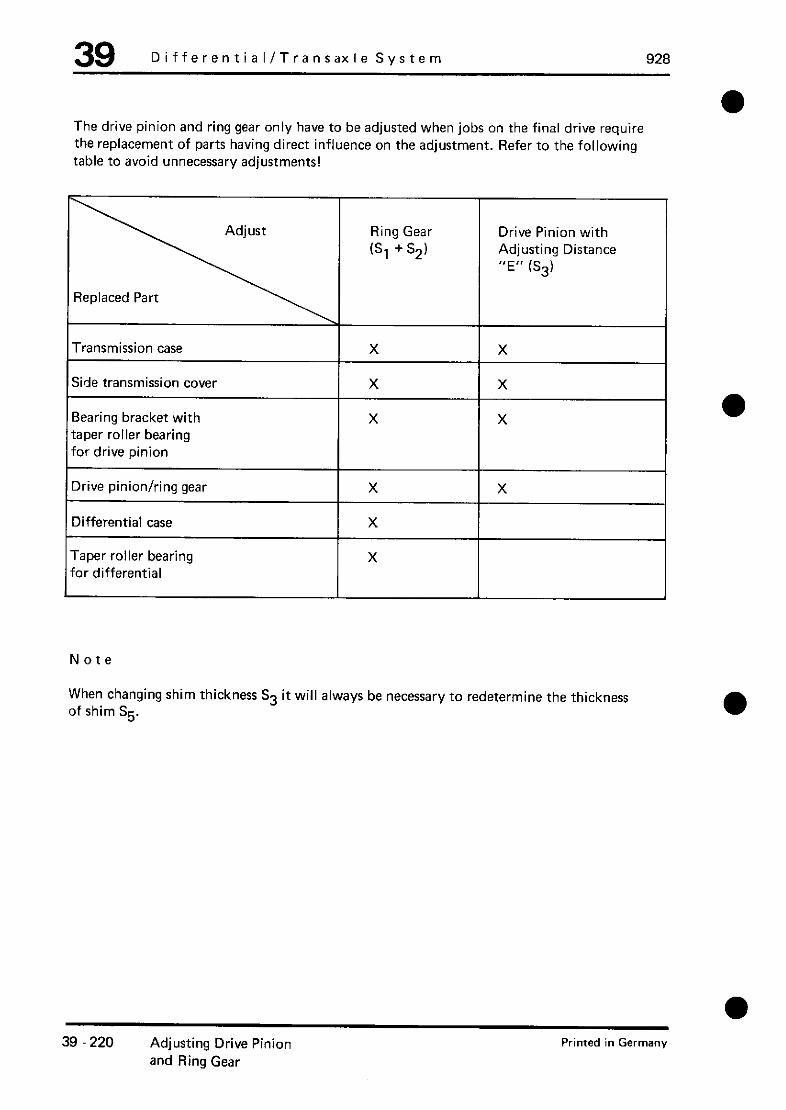
39 Differential/Transaxle System 928
a The drive pinion and ring gear only have to be adjusted when jobs on the final drive require the replacement of parts having direct influence on the adjustment. Refer to the following table to avoid unnecessary adjustments!
Replaced Part
Transmission case
/ ;;vvIdhi; gear
Ring Gear
6, + S.2)
Drive Pinion with Adjusting Distance “E” (SS)
X I x
X X
X X
X X X X
X X X X
X X
X
Note
When changing shim thickness SS it will always be necessary to redetermine the thickness of shim S5.
39 220 Adjusting Drive Pinion and Ring Gear
Printed in Germany

a
928 Differential / Transaxle System 39
Adjusting Pinion
Note
There are different marks and codes for adjustment of the drive pinion/ring gear from 1985 models on.
1 = Pcrsche trademark 2 = Manufacturing code 3 = Serial pair number from 001 to 999 4 = Manufacturing month and year, four digits (e.g. 1084) 5 = Adjusting distance E (e.g. E 71 ,151 6 = Backlash F (e.g. F 0.18) R,= Design distance 70.70 mm E = Adjusting distance (R, + r) r = Deviation from R,
With the new system (e.g. E 71.15) it is no longer necessary to look for the corresponding design distance R. E, the adjusting distance, can be applied direct on the master gage without calculations.
Note
In older model manual transmissions the complete drive pinion had been installed before adjusting the pinion in the case. This is no longer possible from 1985 models on (Transm. Type G 28/10 and G 28/l I), since shim thickness S5 can only after determining the pinion position (shim thickness S3).
Printed in Germany - X, 1984 Adjusting Drive Pinion and Ring Gear
39 - 221

Dlfferentlal.TransaxleSvstem 928
1. Mount bearing assembly on drive pinion and
preload with 20 kN (2 tons).
2. Slide Special Tool 9236 with shim “Ss” on
drive pinion in place of gear set, install 4th
and 5th gear guiding sleeve and tighten col-
lar nut to torque of 300 Nm (217 ftb). Use
Special Tools 9218 and 9219 for this oper- ation.
1
3. Install drive shaft.
4. Install drive pinion without shim S3 and
tighten all bearing cap bolts to torque of 30 Nm (22 ftlb).
5. Install one side bearing cap without an O-
Ring and bolt down with two hexagon head
bolts.
6. Set adjusting ring of universal gage VW
38511 to distance “a”.
7. Slide centering discs VW 385/4 on to univer-
sal gage and screw in gage plunger VW 385/14 with a 20 mm dial gage extension
9150.
8. Insert universal gage in case.
9. Install second side bearing cap wlthout an O-
ring and bolt down with two hexagon head bolts.
IO. Pull out centering discs of universal gage
with the spindle far enough, that the univer
sal page can still be just turned by hand.
-aa ~---,7+~r~ LJ
11. Set master gage VW 385/30 to adjusting distance E (e.g. 71.15 mm).
a = approx. 80 mm
39 - 222 Determlnlng thickness of shim S5 a
Printed in Germany - XXX& 1993
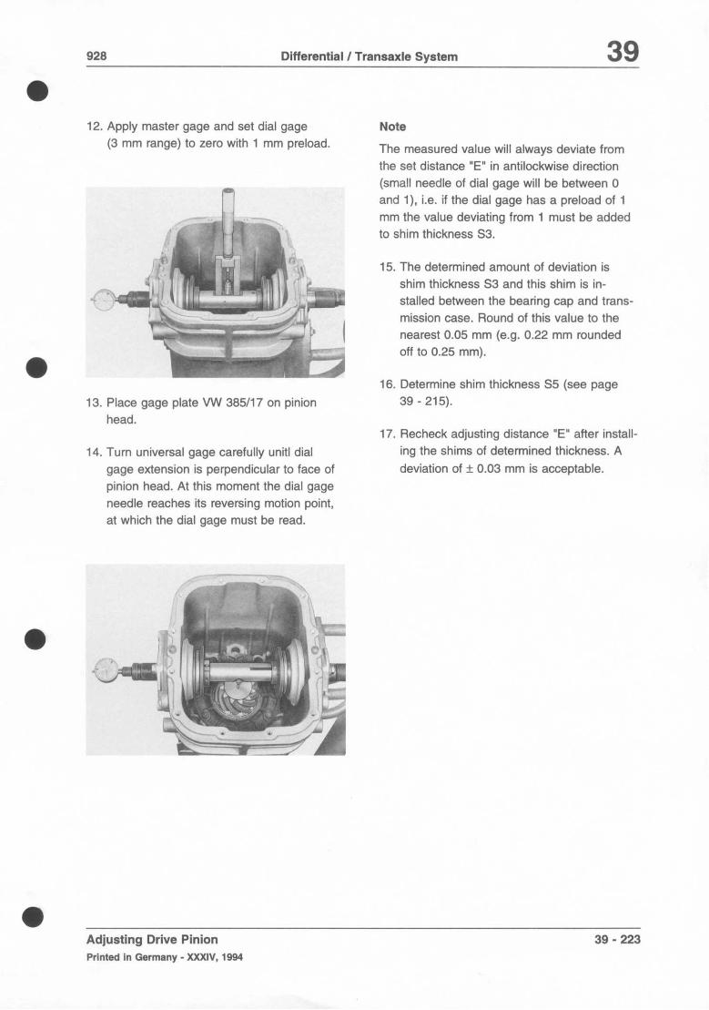
928 Differential / Transaxle System 39
a 12. Apply master gage and set dial gage
(3 mm range) to zero with 1 mm preload.
a
13. Place gage plate VW 365117 on pinion
head.
14. Turn universal gage carefully unit1 dial
gage extension is perpendicular to face of
pinion head. At this moment the dial gage
needle reaches its reversing motion point,
at which the dial gage must be read.
..,i .“.,- . .+I
::!“ .3/‘,., j ;i-/ : ” ,,q ,“p-
--.;a& ; I ,p
k ;-.
il t . g
Note
The measured value will always deviate from
the set distance “E” in antilockwise direction
(small needle of dial gage will be between 0
and i), i.e. if the dial gage has a preload of 1
mm the value deviating from 1 must be added
to shim thickness 53.
15. The determined amount of deviation is
shim thickness S3 and this shim is in-
stalled between the bearing cap and trans-
mission case. Round of this value to the
nearest 0.05 mm (e.g. 0.22 mm rounded
off to 0.25 mm).
16. Determine shim thickness S5 (see page
39 - 215).
17. Recheck adjusting distance “E” after install-
ing the shims of determined thickness. A
deviation of + 0.03 mm is acceptable.
a Adjusting Drive Pinion 39 - 223
Printed In Germany - XXXIV, 1994

928 Differential/Transaxle System 39
ADJUSTING RING GEAR (Stotal)
Note
The drive pinion must not be installed for this adiustment.
1. Install differential with ring gear in case.
2. Install side transmission cover (ring gear end) without shims and tighten all bolts to torque of 22 Nm (16 ftlb).
3. Guide in second side transmission cover without shims carefully.
4. Check gap between transmission case and side transmission cover with a feeler gage.
..- -- N
5. Calculate total shim thickness “Stot”.
Stot = Gap - 0.03 mm (bearing preload)
Example:
Gap Bearing preload
stat
1.25 mm 0.30 mm . . . . .__. _.. . .
g!;:p:~,:
Printed in Germany - X, 1984 Adjusting Drive Pinion 39 - 225 and Ring Gear

928 DifferentiaI/Transaxle System 39
ADJUSTING BACKLASH
1. Install drive pinion with shims S3 determined for drive pinion adjustment and tighten all bearing cap bolts to torque of 30 Nm (22 ftlb).
2. Place differential in case.
.3. Install side transmission covers, placing determined shim “Stot” on ring gear end and tightening all bolts to torque of 22 Nm (16 ftlb).
4. Turn differential in both directions
m several times to settle taper roller bearings.
6. Turn ring gear carefully to stop by hand and set dial gage to zero.
7. Hold drive pinion with locally manufactured hooks and turn back rings gear carefully. Read and note amount of backlash.
-f,m +y ,!i \ fz ,,: ! ‘..
’ i <I. .\’ r\e x I&. ~ j- J il_l< ,,p c-d :
5. Install gages, setting gage plunger VW 388 to distance “a” = 80 mm.
I’ 7 ’ )h:r e-q% A.< 3
Hooks manufactured locally of 30 x 5 mm flat steel.
Printed in Germany - X, 1984 Adjusting Drive Pinion and Ring Gear
39 - 227
928 Differential/Transaxle System 39
DETERMINING THICKNESS OF SHIMS S, AND S2
The measured backlash must be brought to the value specified by the drive pinion/ring gear manufacturer by way of dividing “Stot”.
The specified backlash is inscribed on the rinq gear. Deviations of up to - 0.05 mm are acceptable. The specified backlash must never be exceeded.
Determining Shim Thickness
St (Ring Gear End)
St = Stot (total shim thickness) measured backlash
+ specified backlash (inscribed on ring gear)
Example:
stat -measured backlash
+ specified backlash (e.g. 0.20 mm)
Sl
0.95 mm Q,8&mg.
0.07 mm
s!:amm 0.27 mm
Determining Shim Thickness S2 (Opposite Ring Gear)
s2 = stat -s,
Example:
Stot 0.95 mm
Sl .0.2Z.mm.
S2 :Q,%:am,,
Note
Experience with these drive pinions/ring gears has shown that shims S2 (opposite ring gear) can be selected approx. 10 to 15 % thinner in favour of shims S., (ring gear end).
1. Remove side transmission covers and divide shims “Stot” to give the shim thickness determined for St and S2.
Note
Make sure of a certain amount of backlash when tightening nuts for the side transmission covers. The drive pinion and and ring gear must never be brought to seize.
Printed in Germany X, 1984 Adjusting Drive Pinion 39 - 229 and Ring Gear

39 Drfferential/Transaxle System 928
2. Check backlash and, if necessary, change shims St and S2 again until specified backlash is reached.
3. Check backlash on periphery four times by turning ring gear 90’ each time. The four measurements must not deviate from each other by more than 0.05 mm.
39 - 230 Adjusting Drive Pinion Printed in Germany
and Ring Gear