utilizing chemical looping combustion instead of...
TRANSCRIPT

50 Journal of Gas Technology . JGT
Utilizing Chemical Looping Combustion instead ofFired-Furnace in a Steam Methane Reforming for Enhancement of Hydrogen Production in a Multi Tubular Reactor
Received: May 18, 2015/ Revised: Apr 1, 2017 / Accepted: May 7, 2017
ـــــــــــــــــــ
Abstract
A novel thermally coupled reactor containing steam methane reforming in the endothermic
side and chemical looping combustion as an exothermic side has been investigated in this study.
In this innovative configuration, huge fired furnace of conventional steam reforming process is
substituted by chemical looping combustion in a recuperative coupled reactor. This reactor has three
concentric tubes where the steam methane reforming is supposed to occur in the middle tube and
the inner and outer tubes are considered to be air and fuel reactors of chemical looping combustion,
respectively. Copper is selected as solid oxygen carrier in the chemical looping combustion process.
Both oxidation and reduction of Cu in the air and fuel reactor are exothermic and used as heat
sources for endothermic steam methane reforming. A steady state heterogeneous model of fixed
bed for steam reformer and a moving bed for chemical looping combustion reactor predict the
performance of this new configuration. The counter-current mode is investigated and simulation
results are compared with corresponding predictions of the conventional steam reformer. The
results prove that synthesis gas production is increased in thermally coupled reactor in comparison
with conventional steam reformer.
Keywords: Hydrogen production; Steam reforming of methane; Thermally coupled reactor; Chemical looping combustion; Cu- based oxygen carrier.

51Volume 2 / Issue 1 / May 2017
ــــــــــــــــــــــــــــــــ
I. Introduction
Nowadays, there has been an enormous increase in energy demands due to fast growing of industrial development and population of the world. The shortage of fossil fuels as a main energy sources has brought energy crisis. In order to eliminate fossil fuels dependence, comprehensive research has been carried out on searching alternatives energy resources. Hydrogen is an excellent candidate due to its high potential energy.
1.1. Hydrogen
Hydrogen, the most common element in the earth, has been considered as an attractive energy carrier to support energy consumption. Hydrogen is an environmentally friendly, efficient, safe and sustainable energy source (Lokurlu et al., 2003; Heinzel et al., 2002). The products of hydrogen combustion are water and tiny amount of NO
x which can be reduced
by proper methods. The use of hydrogen in energy sector enhances the security of energy supply and improves economic competitiveness (Muller-Langer et al., 2007). Except the nuclear fuels, hydrogen has the highest calorific value among fuels. A fuel contains higher proportion of hydrogen provides more energy (Sun et al., 2012). Therefore, pure hydrogen would be the leading fuel which can satisfy the increasing demand asked by many processes such as: methanol, electricity, ammonia, aniline, oil refining, fuel cell, vehicle engines, power plants, etc (F.Brown, 2001; Itoh et al., 2008). In fact, hydrogen is a secondary energy produced from traditional processes like: natural gas reforming, gasification of coal, electrolyses water, biomass gasification, catalytic steam reforming of natural gas, dehydrogenation of cyclic hydrocarbons, etc (Sun et al., 2012). It must be noted that hydrogen production must be low in CO
2 emissions and other pollutants.
Among all mentioned technologies, catalytic steam reforming of natural gas is widely used for hydrogen production, 80-85% of the world’s total hydrogen production is provided by this method (Simpson and Lutz, 2007).
1.2. Steam reforming Steam reforming technology is the most
commercial method for synthesis gas (CO, H2)
production, the hydrogen cost is less than hydrogen produced by using renewable energy sources or from gasification of solid fossil fuel (Rostrup-Nielsen, 1993; Tugnoli et al., 2008). Steam reforming may involve several catalytic steps: desulfurization of the fuel, steam reforming of methane, a water gas shift reactor and purification of hydrogen using PSA unit .This method is suitable for light hydrocarbons such as natural gas (mainly CH
4), naphtha,
liquefied petroleum gas (Ryden and Lyngfelt, 2006). Three main catalytic reactions involved in steam reformer reactor are steam reforming of methane (SRM) and the water-gas shift reaction.
Conventional steam reformer consists of vertical tubes packed with Ni-based catalyst located inside huge furnace. The required heat for endothermic reforming reaction is provided by direct combustion of fuel in the furnace. Therefore, the reformer tubes are under very high thermal stress (F.Brown, 2001). In order to solve this issue, the recuperative coupled reactor has been suggested.
1.3. Coupled reactorsRecently, Coupling exothermic and
endothermic reactions are more interested in order to improve the thermal efficiency of process and consequently enhance the production. This type of reactors aims to use energy released by exothermic reaction for proceeding endothermic reaction. In general, the coupled reactors exist into three main classes: direct coupling, recuperative coupling and finally regenerative coupling. At present, recuperative coupling has attracted the most attention of many researchers (Song et al. 2003). Hunter and McGuire (1980) were pioneers in

52 Journal of Gas Technology . JGT
coupling endothermic and exothermic reactions without direct heat transfer. A review on the process intensification for methane steam reforming in a thermally coupled membrane separation technology was studied by Bhat and Sadhukhan (2009). Patel and Sunol (2007) suggested a thermally coupled membrane reactor that is composed of three channels for methane steam reforming. A numerical model for natural gas steam reforming and coupling with a furnace was developed by Ventura and Azevedo (2010). In an interesting idea, Ryden and Lyngfelt (2006) studied steam methane reforming coupled with chemical looping combustion reactor in order to enhance H
2
production with CO2 capture. In their suggested
configuration, reformer tubes are located inside the fuel reactor of chemical looping combustion. A disadvantage of their innovative configuration is erosion of reformer tubes due to harsh environment of the fuel reactor. This issue can be solved by using thermally coupled multitubular reactor which is the main goal of this study.
1.4. Chemical looping combustionChemical looping combustion (CLC) is a high-
quality candidate which has a good potential to become an efficient technique for separating CO
2. It is easy to produce clean energy from
fossil fuel by using this novel method which separates CO
2 inherently (Villa et al., 2003;
Hossain and de Lasa, 2008; Zhang et al., 2009). In chemical looping combustion, a gaseous fuel like natural gas or synthesis gas is burnt with oxygen carrier which is usually a metal oxide and used to transfer oxygen from the combustion air to the fuel. Therefore fuel and combustion air never mixed and combustion products (CO
2,
H2O) do not become diluted with N
2; thus pure
CO2 is obtained after condensation of water.
The process consists of two separate reactors (a fuel and an air reactor) and solid oxygen carrier transports oxygen between them, see Fig. 1 (Anheden and Svedberg, 1998; Ishida et al., 1987
Figure 1. A schematic view of chemical looping combustion
CO2 and H
2O exit from the fuel reactor while
the outlet gas from the air reactor consists of N2
and unused O2. The oxygen carrier is reduced
with fuel which occurs in the fuel reactor
according to:)4)
Where MexO
y is the common abbreviation
for metal oxide in chemical looping combustion and Me
xO
y-1 stands for the reduced oxide which
is then circulated to the air reactor and oxidized according to:
1 21(2 ) (2 )2x y x yn m Me O O n m Me O−+ + ↔ + )5)
Reaction (5) is always exothermic while the amount of energy released or required in reaction (4) depended on choice of oxygen carrier. The net energy in the reactor is equal to the amount of heat released from normal combustion. That is apparent because summation of reaction (4) and (5) yields reaction (6); the conventional complete combustion of fuel.
)6)
The pressure and the temperature of air and fuel reactors are 105Pa and 800-1200OC, respectively. Up to now, researchers suggest various designs for chemical looping combustion including: moving bed, fluidized bed, packed bed and dense membrane reactor but circulating fluidized beds is common to use (Nalbandian et al., 2011; Fan et al., 2008; Son and Kim, 2006; Noorman et al., 2007). Richter and Knoche, (1983) proposed the principle of CLC process to increase the thermal efficiency in fossil fuel fired power plants for the first
2 1 2 2(2 ) (2 )x y n m x yn m Me O C H n m Me O mH O nCO−+ + ↔ + + +
2 1 2 2(2 ) (2 )x y n m x yn m Me O C H n m Me O mH O nCO−+ + ↔ + + +

53Volume 2 / Issue 1 / May 2017
time. Some years later, Lyngfelt and Leckner (1999), successfully ran a 10kW CLC prototype at Chalmers University of Technology. Choice of oxygen carriers is one of the critical steps in CLC and numbers of studies have been done on this course. An appropriate oxygen carrier has the following properties:
1) Have suitable rate of reaction both reduction and oxidation.
2) Be thermodynamically suitable to convert fully the fuel to CO
2 and H
2O.
3) Have good strength so that resistance to attrition and breakage.
4) Does not tend to agglomeration.5) Be cheap and healthy. 6) Have high melting point.7) Have low tendency to become deactivate
with carbon and sulphur.Based on above properties, some metal oxides
like Ni, Cu, Fe, Mn could be probable oxygen carriers (Cho, 2005; Johansson, 2007; Adanez et al., 2004). In this work, Cu is used as solid particle. An advantage of chemical looping combustion compared with ordinary combustion would be the inherent capture of CO
2 from the rest of
the flue gas without spending energy. (Ryden et al., 2009). Also, since indirect combustion in chemical looping combustion does not involve high temperature flame, the formation of NO
x is
avoided.
1.5 Literature reviewMany efforts have been done for improvement
of steam methane reforming. Arab Aboosadi et al. (2011a) have considered a novel integrated thermally coupled configuration for methane steam reforming. In their simulated reactor, hydrogenation of nitrobenzene to aniline in the exothermic side is used as a heat source for endothermic reaction of steam methane reforming. The exothermic reaction takes place in the shell side and endothermic reaction occurs in the tube side. Moreover, Arab Aboosadi et al. (2011b) simulated and optimized tri-reformer (TRM) reactor for producing synthesis gas using differential evolution (DE) method. In TRM process, steam reforming, CO
2 reforming and
partial oxidation of methane occurred in a single reactor. Finally, methane steam reforming and hydrogenation of nitrobenzene in hydrogen
perm-selective membrane thermally coupled reactor has been optimized using differential evolution (DE) method by Rahimpour et al. (2012). Recently, Rahimpour et al. (2013) have simulated methane steam reforming technology coupled with fluidized bed chemical looping combustion using Fe- based as oxygen carrier. From previous studies, it is found that there is no modeling information available in the literature about using chemical looping combustion as a heat source for steam methane reforming in order to increase H
2 production. Therefore, it
was decided to first study on this system.
1.6. ObjectivesThe main goal of this study is enhancement
of hydrogen production theoretically in a thermally coupled steam reformer (TCSR). The endothermic and exothermic reactions are chosen the steam methane reforming and indirect combustion of methane in a chemical looping combustion process, respectively. The motivation is to combine the energy efficient concept of coupling exothermic and endothermic reactions and enhancement of hydrogen production. A steady state 1-D heterogeneous model of the thermally coupled multitubular reactor is used to estimate the performance of the proposed reactor. Ultimately, the simulation results of the TCSR were compared with the ones in conventional steam methane reforming.
ــــــــــــــــــــــــــــــــــــــــــــــــــــــــــ
2. Process description
2.1. Conventional steam reformerFig. 2 represents the schematic diagram of
a conventional Lurgi-steam methane reformer (CR) to produce syngas for methanol synthesis process. This reactor has vertical tubes which are located inside a huge fired furnace. Natural gas is mixed with steam and entered to the steam reformer tubes as feed. Vertical tubes is packed with Ni- based catalyst, the generated heat related to natural gas combustion in burners of furnace transfers to reformer tubes (Methanol documents of Lurgi in Assaluyeh-Iran.). Table 1 shows the specification of reactor and operating conditions of the CR

54 Journal of Gas Technology . JGT
Figure 2. A schematic diagram of conventional steam methane reforming
Table 1: The specification of reactor and operating couditions
UnitValueParameter
mol% Feed composition
[-]1.72CO2
[-]0.02CO
[-]5.89H2
[-]32.59CH4
[-]1.52N2
[-]58.26H2O
ºK793 Inlet temperature
bar a40 Inlet pressure
Kmol/h9129.6Total feed gas flow
[-]184Number of tubes(in 4 rows)
mm125 Inside diameter
m12Heated length
m327.8Catalyst volume filled in (total)
bar g41Design pressure
ºK1063 Design temperature
Catalyst properties
HOLE 10rings
Catalyst shape
mm19 ×16 Particle size
0.4Void fraction
Kcal/m2h68,730 Heat load on(tube(100% design case
GJ/h248.2 Reformer duty (100%(design case
Shell side
Combustion air
ºK603Temperature
bar1Pressure
sm3/h114,313Flow rate
(Feed gas(fuel
ºK307Temperature
bar3Pressure
sm3/h29,608Flow rate
2.2. Thermally coupled steam reformer (TCSR)A conceptual schematic diagram of TCSR is
shown in Fig .3. Chemical looping combustion of methane is used as exothermic reaction instead of normal combustion of natural gas in conventional steam reformer. This reactor is consisted of three concentric tubes, the inner tube is used as air reactor of CLC and the outer tube is assumed to be fuel reactor. Endothermic reaction of steam methane reforming takes place on the Ni-based catalyst counter currently in the middle tube. Air fed to the air reactor from the bottom of the reactor and natural gas combined with steam is fed to steam reformer from top of the middle reactor. A small part of steam reformer product stream recycled and combined with CH
4 to use as feed for fuel
reactor. Cu as an oxygen carrier enters into air reactor of CLC from top of the reactor, moves down ward and after oxidation exits in the form of CuO from bottom of reactor. Then, copper oxide circulates in a loop and after regeneration transfers to fuel reactor and reduced with CH
4.The specific properties and operational
conditions of TCSR are tabulated in Table 2. Table 1 (excluding data in the shell side) is also used for endothermic side of thermally coupled steam reformer.

55Volume 2 / Issue 1 / May 2017
Figure 3. A conceptual schematic diagram of thermally coupled steam reformer
Table 2. The specific properties and operational conditions of TCSR
Value Parameter
793Inlet temperature of endothermic side (*K)
101.325Inlet pressure of air reactor (kPa)
101.325Inlet pressure of fuel reactor (kPa)
0.1Inner tube or air reactor diameter (m)
0.1601Middle tube or steam reformer diameter (m)
0.1887Outer tube or fuel reactor diameter (m)
12Length of the reactor (m)
Feed composition
Air reactor (composition mol %)
20.94O2
78.08 N2
0.98Ar
Oxygen carrier properties (CuO/Al
2O
3)
0.1-0.3Particle size (mm)*
0.57*Porosity
1800*(Apparent density (kg m-3
80402*(Molar density of CuO (molm-3
140252*(Molar density of Cu (molm-3
0.01(Flow rate(kg/s
Obtained from (García-Labiano *(et al., 2004
ـــــــــــــــــــــــــــــــــــــــــــــــــــــــــــــــــــــــــــــــــــــــ
3. Reaction scheme and kinetics
3.1. Steam methane reforming (endothermic side)
Three main reaction reactions occurred in steam reformer are steam reforming of methane and the water-gas shift reaction (Equations 1–3). The reaction rates of CR reactions proposed by Xu and Froment are as follows (Xu and Froment, 1989; Xu et al., 2002):
2
3
5.21
11)( 2
24
2ϕ
×−=I
COHOHCH
H KPP
PPPkR )7)
2
42
5.32
21)( 22
24
2ϕ
×−=II
COHOHCH
H KPP
PPPkR )8)
23
31)( 2
2
2ϕ
×−=III
COHOHCO
H KPP
PPPkR )9)
2
2244221
H
OHOHCHCHHHCOCO P
PKPKPKPK ++++=ϕ )10)
The reaction equilibrium constants and Arrhenius kinetic parameters are listed in Table 3. Table 4 shows the Van’t Hoff parameters for species adsorption
3.2. Chemical looping combustion (exothermic sides)
In general, metal oxides are used as oxygen carrier in chemical looping combustion. The focus of the literature is on Ni, Cu, Fe and Mn that each one has specific advantage. In this work, Cu is selected as oxygen carrier because reduction of Cu is exothermic while for most other materials, it is endothermic.
Additionally, it is environmentally benign and reactive (Jerndal et al., 2006). The reduction and
Table 2. Continued...

56 Journal of Gas Technology . JGT
Equilibrium constant
Re
acti
on
, j
24010015 0.51.17 10 ( )bar×226830exp 30.114 ( )Is
K barT
−= +
1
24390014 0.52.83 10 ( )bar×)( 2barKKK IIIIII ⋅=2
671305 15.43 10 ( )bar −×3 )036.44400exp( −=
sIII T
K
Table 3. The reaction equilibrium constants and Arrhenius kinetic parameters for steam reforming reactions
Table 4. The Van’t Hoff parameters for species adsorption
ΔHiK0i
(bar-1)Components
-3828010-4×6.65CH4
-7065010-5×8.23CO
-8290010-9×6.12H2
88680105×1.77H2O
oxidation reaction of Cu in fuel and air reactor are as follows:
)11)
01073 202.5 /H kJ mol∆ = − )12)
One of the main drawbacks of this material is its low melting point (1085ºC). This makes necessary to perform at temperatures lower than its melting point in order to avoid agglomeration and loss of activity (Noorman et al. 2010). In order
to describe the kinetics of metal oxide reduction and oxidation, many efforts have been done. In this way, two general types of models can be found in the literature for chemical looping combustion: one is nucleation growth model referred to as Avrami Erofeev models and the other is shrinking core models which are common method (Levenspiel, 1998; Koga and Harrison, 1984). The following equations described the unreacted shrinking core model for gas- solid reactions:
57Volume 2 / Issue 1 / May 2017
)13)
Where ,m iρ is the molar density of
reactive material in the oxygen carrier, iL is
the layer thickness of reacting solid, jb is the stoichiometric factor in reaction j (j=oxidation,
reduction), jk is the chemical reaction rate constant in reaction j. The rate of oxidation and reduction can be calculated by following equation:
)14)
In this study, the kinetics data for the reduction and oxidation of CuO/Al
2O
3 with methane and
air were used (García-Labiano et al., 2004). Table 5 shows these kinetics parameters for both oxidation and reduction reactions
Table 5. The kinetics parameters of reactions in exothermic side for Cu based oxygen carrier
Air reactorFuel reactor Kinetic
parameters
10.4n
15±260±3 E
4.7 ×10-64.5×10-4K0(mol-nm3n-2s-1)
ـــــــــــــــــــــــــــــــــــــــــــــــــــــــــــــــ
4. Mathematical model
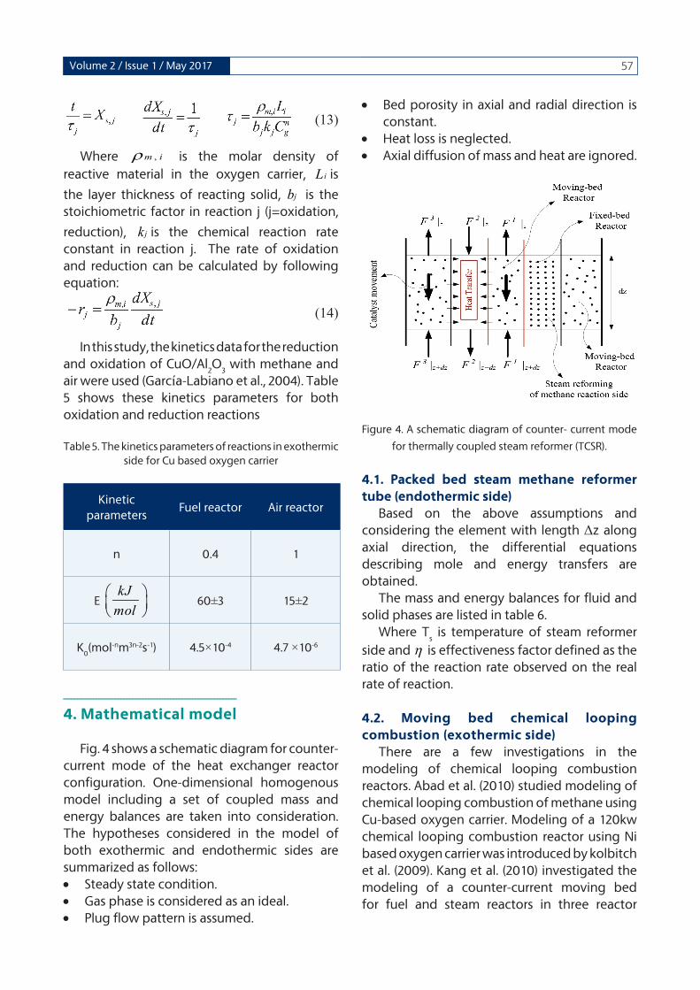
Fig. 4 shows a schematic diagram for counter-current mode of the heat exchanger reactor configuration. One-dimensional homogenous model including a set of coupled mass and energy balances are taken into consideration. The hypotheses considered in the model of both exothermic and endothermic sides are summarized as follows:• Steady state condition.• Gas phase is considered as an ideal.• Plug flow pattern is assumed.
• Bed porosity in axial and radial direction is constant.
• Heat loss is neglected.• Axial diffusion of mass and heat are ignored.
Figure 4. A schematic diagram of counter- current mode
for thermally coupled steam reformer (TCSR).
4.1. Packed bed steam methane reformer tube (endothermic side)
Based on the above assumptions and considering the element with length Δz along axial direction, the differential equations describing mole and energy transfers are obtained.
The mass and energy balances for fluid and solid phases are listed in table 6.
Where Ts is temperature of steam reformer
side and η is effectiveness factor defined as the ratio of the reaction rate observed on the real rate of reaction.
4.2. Moving bed chemical looping combustion (exothermic side)
There are a few investigations in the modeling of chemical looping combustion reactors. Abad et al. (2010) studied modeling of chemical looping combustion of methane using Cu-based oxygen carrier. Modeling of a 120kw chemical looping combustion reactor using Ni based oxygen carrier was introduced by kolbitch et al. (2009). Kang et al. (2010) investigated the modeling of a counter-current moving bed for fuel and steam reactors in three reactor
kJmol

58 Journal of Gas Technology . JGT
Table 6. Mass and energy balance and boundary conditions for solid and fluid phases in packed bed steam methane reformer tube (endothermic side).
ValueParameter
)16)
)17)
( ) 0g g si bv i i ia ck y y r ρ− + =
( ) ( ) ( ) ( ) 0p
g gi is gt
v f s s f s f a s a
c d FT D Da h T T U T T U T TA dz A A
π π− + − − − − − =
1( ) ( ) 0
Ng s
v f b i fis si
a h T T r Hρ=
− + ∆ =∑
Mass and energy balancefor solid phase
)18)( )1 ( ) 0gii
gt s g
v i ia
d F ya ck y y
A dz− + − =
Mass andenergy balancefor fluid phase
)19)g0j
gj PP = ,,0,
gji
gji yy = ,TT g
0jgj = ,0=z Boundary
condition
chemical looping (TRCL). Their results show that the heat transfer from oxygen carrier to gas phase is fast so that the temperature of gas and solid phases become equal along the reactor. Kang et al., 2012 suggested that a counter-current moving bed is expected to obtain high CO
2 selectivity in comparison with fluidized bed
reactor. To obtain mass and energy balances in fuel and air reactor, an element with length Δz was considered. Table 7 shows the equations of mass and energy balances for fluid and solid phases for both air and fuel reactor.
Where spC
(J/Kg.K) is the heat capacity of
the solids, sF (kg/s) is the solid loading.
4.3 Auxiliary correlationsIn order to complete the mentioned
simulation equations, auxiliary correlations containing physical properties of components, mass and heat transfer coefficients should be added, see table 8.
ـــــــــــــــــــــــــــــــــــــــــــــــــــــــــ
5. Numerical solution
A governing equations of this model consists of a set of differential algebraic equations
including mass balances for all sides with given boundary conditions incorporate the reaction rates as well as basic assumptions. In order to solve the set of equations, back-ward finite difference approximation was used. The reactor length is then divided into 100 separate sections and the Gauss-Newton method in MATLAB programming environment was used to solve the non-linear algebraic equations in each section. All parameters of chemical looping combustion reactors like inlet fuel reactor compositions and flow rates are determined by using trial and error method.
ــــــــــــــــــــــــــــــــــــــــــــــــــــــــــــــــــــ
6. Results and Discussion
Model validation was carried out by comparing the simulated results of steam reforming side of TCSR with the observed experimental data of the industrial tubular fixed bed steam reformer reactor which is shown in Table 9. According to this table, this simulation results is in good agreement with experimental data. The simulation results of the reactor in the exothermic side are not compared with any reference case .
)15)

59Volume 2 / Issue 1 / May 2017
Table 7. Mass and energy balance and boundary conditions for solid and fluid phases in moving bed chemical looping combustion
ValueParameter
(20)
(21)
( )1 0b
s sj
j
d F yr b
A dzρ− + =
( )( ) ( ) 0
s sst j g s
v f j j j Rxn
d F Tcp a h T T br HA dz
ρ− + − + −∆ =∑
Mass and energybalance
for solid phase
(22)
(23)
)(1 0g
j
b
g
j
d F yr
A dzρ+ =
( )( ) ( ) 0
g ggt j s g g gi
v f j j s j
d F T Dcp a h T T U T TA dz A
π+ − + − =
Mass and energybalance
for fluid phase
(24)00; , 0,g g s g gi iout i ioutz y y y T T= = = = Boundary
condition
Table 8. Auxiliary correlations.
Parameter Equation Number
component heat capacity(25)
mixture heat capacity(26)
viscosity(27)
overall heat transfer coefficient (28)
heat transfer coefficient between gas phase and reactor
wall(29)
Pressure drop (30)
243
C1
TC
TC1
TC 2
++=µ
oo
i
w
ioi
i hAA
LKDDA
hU1
2)ln(11++=
π

60 Journal of Gas Technology . JGT
Table 9. Comparison between model prediction and
plant data.
CRPlantParameter
720.5710Temperature (ºK)
CRPlantComposition (mol %)
5.705.71CO2
3.183.15CO
31.4531.39H2
20.3720.41CH4
1.301.29N2
38.0138.05H2O
26.626.5Methane conversion (%)
In this section, predicted mole fraction, pressure drop and temperature profiles in the counter current coupled reactor are presented. The results are shown in the following figures. One definition is introduced to examine the methane conversion through the reactor length:
)31)
6.1.1. Thermal behaviorFig. 5(a) shows the axial temperature profiles
in conventional steam reformer reactor (CR) as well as the endothermic side of thermally coupled steam reformer (TCSR). As seen, the temperature profile of CR is linear while it has a curvy profile in the TCSR. Although the initial temperature of both configurations is the same, the temperature profile of TCSR is higher than that of CR as a result of distribution of solid oxygen carriers in the exothermic side which improves overall heat transfer coefficient. Since the rates of endothermic reactions are increased as temperature increases, hydrogen production is improved in TCSR. In order to make a driving force for heat transfer from exothermic side
to endothermic side, the temperature of endothermic side must always lower than that of exothermic side. Fig. 5(b) represents the temperature profile of exothermic side of fuel reactor. In general, the highest temperature in thermally couple reactors is related to exothermic side where heat generation is occurring. Part of generated heat from air and fuel reactors is used for driving endothermic reaction and the rest is used to heat the reaction mixtures in three sides of TCSR. Although steam reforming is an endothermic process, its temperature increased along the reactor; it happens because the generated heat in exothermic side is so higher than consumed heat in endothermic side. The most heat transfer is occurring at the beginning of the reactor because of high temperature difference between endothermic side and exothermic sides. It is understood from Fig. 5(b) that the variation of temperature of fuel reactor is 70 K and the outlet temperature is 1160 K; fortunately, this temperature is lower than melting point of copper so that no agglomeration and loss of activity occur in the chemical looping combustion.
Figure 5(a). Variation of temperature for endothermic side of TCSR and CR.
6.1.2. Molar behaviorThe total molar flow rate of endothermic
side in CR and TCSR are compared in Fig. 6. The total molar flow rate of TCSR is higher than that of CR. The temperature profile of endothermic

61Volume 2 / Issue 1 / May 2017
side and total molar flow rate have the same trend, because these two parameters are proportional to each other (see fig 5(a)). As total molar flow rate increases, the residence time and conversion decreases.
00.10.20.30.40.50.60.70.80.911090
1100
1110
1120
1130
1140
1150
1160
1170
Dimensionless length
Tem
pera
ture
(K)
Fuel reactor
Figure 5(b). Variation of temperature for exothermic side of fuel reactor
0 0.1 0.2 0.3 0.4 0.5 0.6 0.7 0.8 0.9 113
14
15
16
17
18
19
Dimensionless length
Tota
l mol
ar fl
ow ra
te (m
ole/
s)
Endothermic side
CRTCSR
Figure 6. Comparison of total molar flow rate between endothermic sides of TCSR and CR.
Fig.7 (a)-(d) presents the comparison of mole fraction of components in endothermic side of TCSR and CR. Fig.7 (a) and (b) illustrate the mole fraction of hydrogen and carbon monoxide (CO) along the reactor at steady state. Hydrogen and CO are the most desirable products of steam reforming and fortunately their mole fractions increase in the coupled configuration in comparison with CR, because thermal effect of coupled reactor provides a good condition for heat transfer and consequently more
production. The CH4 mole fraction is depicted
in Fig. 7 (c). As can be seen, the consumption rate of CH
4 as a main reactant in steam methane
reforming process increases in coupled configuration. According to this figure, CH
4
conversion reaches to 52.6 % in TCSR while 26% methane conversion occurs in CR. The difference between CH
4 mole fraction profiles in CR and
TCSR is owing to the temperature increase in endothermic side which causes the increase in reaction rate and CH
4 consumption. CO
2 mole
fraction as an undesired product in TCSR is compared with the one in CR in Fig.7 (d). At the reactor entrance, the CO
2 mole fraction in TCSR
is higher than the one in the CR configuration but at the end of reactor it becomes lower.
0 0.1 0.2 0.3 0.4 0.5 0.6 0.7 0.8 0.9 10.05
0.1
0.15
0.2
0.25
0.3
0.35
0.4
0.45
0.5
Dimensionless length
H2 m
ole
fract
ion
CRTCSR
Figure 7(a). Comparison of H2 mole fraction along the
reactor axis between endothermic side of TCSR and CR.
0 0.1 0.2 0.3 0.4 0.5 0.6 0.7 0.8 0.9 10
0.01
0.02
0.03
0.04
0.05
0.06
0.07
0.08
0.09
Dimensionless length
CO
mol
e fra
ctio
n
CRTCSR
Figure 7(b). Comparison of CO mole fraction along the reactor axis between endothermic side of TCSR and CR.

62 Journal of Gas Technology . JGT
Fig. 8 (a)-(c) demonstrates the mole fractions of components in exothermic side of fuel reactor. As the reaction scheme in fuel reactor shows, the mole fraction of CH
4, as reactant,
decreases linearly along the fuel reactor; it is shown in Fig. 8 (a). H
2O and CO
2 are the main
products of reduction reaction in fuel reactor and their mole fraction increases (see Fig 8(b) and (c)) and it can be said that all component behaviors are normal
0 0.1 0.2 0.3 0.4 0.5 0.6 0.7 0.8 0.9 10.1
0.15
0.2
0.25
0.3
0.35
Dimensionless length
CH
4 mol
e fra
ctio
n
CRTCSR
Figure 7(c). Comparison of CH4 mole fraction along the
reactor axis between endothermic side of TCSR and CR.
0 0.1 0.2 0.3 0.4 0.5 0.6 0.7 0.8 0.9 10.015
0.02
0.025
0.03
0.035
0.04
0.045
0.05
0.055
0.06
Dimensionless length
CO
2 mol
e fra
ctio
n
CRTCSR
Figure 7(d). Comparison of CO2 mole fraction along the
reactor axis between endothermic side of TCSR and CR.
00.10.20.30.40.50.60.70.80.910.118
0.12
0.122
0.124
0.126
0.128
0.13
0.132
Dimensionless length
CH 4 m
ole
fract
ion
Fuel Reactor
Figure 8(a). Profile of CH4 mole fraction along the reactor
axis in the fuel reactor of exothermic side in TCSR
00.10.20.30.40.50.60.70.80.91
0.286
0.288
0.29
0.292
0.294
0.296
0.298
0.3
Dimensionless length
H2O
mol
e fra
ctio
nFuel reactor
Figure 8(b). Profile of H2O mole fraction along the reactor
axis in the fuel reactor of exothermic side in TCSR
00.10.20.30.40.50.60.70.80.910.053
0.054
0.055
0.056
0.057
0.058
0.059
0.06
0.061
0.062
Dimensionless length
CO
2 mol
e fra
ctio
n
Fuel Reactor
Figure 8(c). Profiles of CO2 mole fraction along the
reactor axis in the fuel reactor of exothermic side in TCSR
63Volume 2 / Issue 1 / May 2017
6.1.3. Pressure dropFig. 9 shows the pressure along steam
methane reforming for both conventional and thermally coupled steam reformer. The Ergun Equation (which is equation (23)) usually used to calculate pressure drop through catalytic packed bed.
Since total molar flow rate and temperature profile of thermally coupled steam reformer is higher than temperature profile of conventional steam reformer, the density of gas phase and consequently the velocity and related viscose losses of TCSR become higher. As a result, pressure drop profile through this reactor is higher than conventional steam reformer.
0 0.1 0.2 0.3 0.4 0.5 0.6 0.7 0.8 0.9 130
31
32
33
34
35
36
37
38
39
40
Dimensionless length
Pre
ssur
e (b
ar)
CRTCSR
Figure 9. Pressure drop along the endothermic side CR and TCSR.
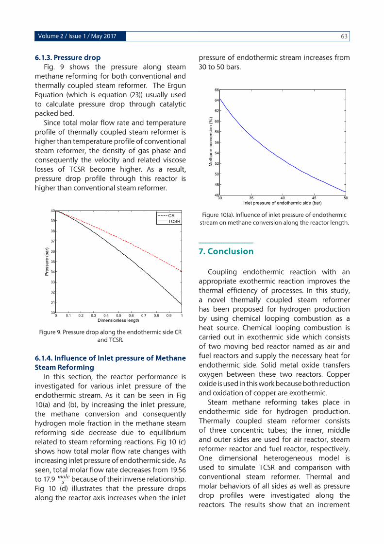
6.1.4. Influence of Inlet pressure of Methane Steam Reforming
In this section, the reactor performance is investigated for various inlet pressure of the endothermic stream. As it can be seen in Fig 10(a) and (b), by increasing the inlet pressure, the methane conversion and consequently hydrogen mole fraction in the methane steam reforming side decrease due to equilibrium related to steam reforming reactions. Fig 10 (c) shows how total molar flow rate changes with increasing inlet pressure of endothermic side. As seen, total molar flow rate decreases from 19.56 to 17.9 because of their inverse relationship. Fig 10 (d) illustrates that the pressure drops along the reactor axis increases when the inlet
pressure of endothermic stream increases from 30 to 50 bars.
30 35 40 45 5046
48
50
52
54
56
58
60
62
64
66
Inlet pressure of endothermic side (bar)M
etha
ne c
onve
rsio
n (%
)Figure 10(a). Influence of inlet pressure of endothermic
stream on methane conversion along the reactor length.
ـــــــــــــــــــــــــــــــ
7. Conclusion
Coupling endothermic reaction with an appropriate exothermic reaction improves the thermal efficiency of processes. In this study, a novel thermally coupled steam reformer has been proposed for hydrogen production by using chemical looping combustion as a heat source. Chemical looping combustion is carried out in exothermic side which consists of two moving bed reactor named as air and fuel reactors and supply the necessary heat for endothermic side. Solid metal oxide transfers oxygen between these two reactors. Copper oxide is used in this work because both reduction and oxidation of copper are exothermic.
Steam methane reforming takes place in endothermic side for hydrogen production. Thermally coupled steam reformer consists of three concentric tubes; the inner, middle and outer sides are used for air reactor, steam reformer reactor and fuel reactor, respectively. One dimensional heterogeneous model is used to simulate TCSR and comparison with conventional steam reformer. Thermal and molar behaviors of all sides as well as pressure drop profiles were investigated along the reactors. The results show that an increment
smole
smole
smole

64 Journal of Gas Technology . JGT
about 47% occurs in hydrogen mole fraction in TCSR compared with conventional steam reformer. In addition, the methane conversion in steam reforming reaches to 52.6%. Finally, these preliminary simulation results demonstrate that substitution of huge fired-furnace of conventional steam reformer with chemical looping combustion process is highly efficient for synthesis gas production.
ـــــــــــــــــــــــــــــــــ
Nomenclature
Aa Cross section area of each tube (m2)
av specific surface area of catalyst pellet( m2 /m_3)
b Stochiometric factor for reaction in CLC
Cg Gas concentration (mol m-3)
cpg Specific heat of the gas at constant pressure (j mol-1)
cps Heat capacity of oxygen carrier in CLC (j kg-1 k-1)
Di Inside diameter of steam reformer (m)
Ft Total flow rate per each reaction side (mol s-1)
K1 Reaction rate constant for 1st rate equation of steam reforming(mol kg-1s-1)
K2 Reaction rate constant for 2nd rate equation of steam reforming (mol kg-1s-1)
K3 Reaction rate constant for 3rd rate equation of steam reforming (mol kg-1s-1)
Kj Chemical reaction constant of j reaction (j=oxidation, reduction)(mol1-nm3n-2s-1)
Li Layer thickness of the reacting solid (m)
N Number of components
n Reaction order
R1 First rate of reaction for steam reforming of CH
4 (reaction 4) (mol kg-1 s-1)
R2 Second rate of reaction for steam reforming of CH
4(reaction 5) (mol kg-1 s-1)
R3 Water gas shift reactor (reaction 6)(mol kg-1 s-1)
rj Rate of reaction occurs in chemical looping combustion based on gas phase (mol m-3 s-1)
t Reaction time (s)
Ts Bulk gas phase temperature related to steam reformer (k)
Ta Temperature of air reactor (k)
Tf Temperature of fuel reactor (k)
Uf Overall heat transfer coefficient between fuel and steam reforming reactors (W m-2k-1)
Ua Overall heat transfer coefficient between air and steam reforming reactors (W m-2k-1)
Xs Solid conversion in the chemical looping reactor
Subscripts
0 Inlet condition
a Air reactor
f Fuel reactor
g Gas phase
i Chemical species
j Oxidation, reduction
s Solid phase
Greek letters
ΔHfi Enthalpy of formation of component (J mol-1)
ΔHRXn Enthalpy of reaction (J mol-1)
pb Density of catalyst bed (kg m-3)
ρmi Molar density of reactive material in the oxygen carrier (mol m-3)
ƞ Effectiveness factor used for the intra particle transport limitation
ــــــــــــــــــــــــReferences
1. Abad, A., Adánez, J., Garcı´a-Labiano, F., F. de Diego, L., Gayán, P., 2010. Modeling of the chemical-looping combustion of methane using a Cu-based oxygen-carrier. Combust Flame. 157, 602-15.
2. Adanez, J., F.de Diego, L., Garcia-Labiano, F., Gayan, P., Abad, A., 2004. Selection of oxygen carriers for chemical looping combustion.
65Volume 2 / Issue 1 / May 2017
Energy. Fuels. 18, 371-377. 3. (3)Anheden, M., Svedberg, G., 1998. Exergy
analysis of chemical looping combustion systems. Energy. Convers. Manage. 39, 1967-1980.
4. Arab Aboosadi, Z., Rahimpour, M.R., Jahanmiri, A., 2011a. A novel integrated thermally coupled configuration for methane-steam reforming and hydrogenation of nitrobenzene to aniline. Int. J. Hydrogen. Energy. 36, 2960-2968.
5. Arab Aboosadi, Z., Jahanmiri, A.H., Rahimpour, M.R., 2011b. Optimization of tri-reformer reactor to produce synthesis gas for methanol production using differential evolution (DE) method. Appl. Energy. 88, 2691-2701.
6. Bhat, S.A., Sadhukhan, J. 2009. Process intensification aspects for steam methane reforming: an overview. AIChE J. 55,408-422.
7. Cho, P., 2005. Development and characterization of oxygen-carrier materials for chemical looping combustion. Doctoral thesis, Chalmers University of Technology, Goteborg, Sweden.
8. Fan, L., Li, F., Ramkumar, S., 2008. Utilization of chemical looping strategy in coal gasification processes. Particuology. 6, 131-142.
9. F. Brown, L., 2001. A comparative study of fuels for on-board hydrogen production for fuel-cell-powered automobiles. Int. J. Hydrogen. Energy. 26, 381-397.
10. García-Labiano, F., F.de Diego, L., Adánez, J., Abad, A., Gayán, P., 2004. Reduction and oxidation kinetics of a copper-based oxygen carrier prepared by impregnation for chemical-looping combustion. Ind. Eng. Chem .Res. 43, 8168-8177.
11. Gosiewski, K., Bartmann, U., Moszczynski, M., Mleczko, L., 1999. Effect of intraparticle transport limitations on temperature profiles and catalytic performance of the reverse-flow reactor for the partial oxidation of methane to synthesis gas. Chem. Eng. Sci. 54, 4589–602.
12. Heinzel, A., Vogel, B., Hubner, P., 2002. Reforming of natural gas-hydrogen generation for small scale stationary fuel cell systems. J. Power. Sources. 105(2), 202-7.
13. Hossain, M.M., L.de Lasa, H., 2008. Chemical looping combustion (CLC) for inherent CO2 separations- a review. Chem. Eng. Sci. 63, 4433-51.
14. Hunter, J.B., McGuire, G., 1980. Method and apparatus for catalytic heat-exchange. US Patent, 4 214 867.
15. Ishida, M., Zheng, D., Akehata, T., 1987. Evaluation of a chemical looping combustion power- generation system by graphic exergy analysis. Energy. 12, 147-154.
16. Itoh, N., Watanabe, S., Kawasoe, K., Sato, T., Tsuji, T., 2008. A membrane reactor for hydrogen storage and transport system using cyclohexane-methycyclohexane mixtures. Desalination. 234, 261-269.
17. Jerndal, E., Mattisson, T., Lyngfelt, A., 2006. Thermal analysis of chemical-looping combustion. Chem. Eng. Res. Des. 84, 795-806.
18. Johansson, M., 2007. Screening of oxygen-carrier particles based on iron-, manganese-, copper-, nickel oxides for use in chemical looping technologies. Doctoral thesis, Chalmers University of Technology, Goteborg, Sweden.
19. Kang K.S., Kim C.H., Bae K.K., Cho W.C., Jeong, S.U., Kim, S.H., Park, C.S., 2012. Modeling a counter-current moving bed for fuel and steam reactors in the TRCL process. Int. J. Hydrogen. Energy. 37, 3251-3260.
20. Kang K.S., Kim C.H., Bae K.K, Cho W.C, Kim S.H, Park C.S., 2010. Oxygen-carrier selection and thermal analysis of the chemical-looping process for hydrogen production. Int. J. Hydrogen. Energy. 35, 12246-54.
21. Koga, Y., Harrison, L.G., 1984. In: Bamford C.H, Tipper C.F.H, Compton R.G. (Eds.), Comprehensive chemical kinetics. Elsevier, Amsterdam. 21, 120.
22. Kolbitsch, P., Pröll, T., Hofbauer, H., 2009. Modeling of a 120 kW chemical looping combustion reactor system using a Ni-based oxygen carrier. Chem. Eng. Sci. 64, 99 –108.
23. Levenspiel, O., 1998. Chemical reaction engineering. John wiley and sons, New York.
24. Lokurlu, A., Grube, T., Hohlein, B., Stolten, D., 2003. Fuel cells for mobile and stationary applications- cost analysis for combined heat and power stations on the basis of fuel cells. Int. J. Hydrogen. Energy. 28(7), 703-11.
25. Lyngfelt, A., Leckner, B., 1999. Technologies for CO
2 separation. In minisymposium on CO
2
capture and storage. Goteborg: Chalmers University of Technology and University of

66 Journal of Gas Technology . JGT
Gothenburge.26. Muller-Langer, F., Tzimas, E., Kaltschmidtt,
M., Peteves, S., 2007. Techno-economic assessment of hydrogen production processes for the hydrogen economy for the short and medium term. Int. J. Hydrogen. Energy. 32, 3797-810.
27. Nalbandian, L., Evdou, A., Zaspalis, V., 2011. La1-x Srx MyFe1-yO3-s perovskites as oxygen-carrier materials for chemical-looping reforming. Int. J. Hydrogen. Energy. 36, 6657-6670.
28. Noorman, S., van Sint Annaland, M., Kuipers, H, 2007. Packed bed reactor technology for chemical-looping combustion. Ind. Eng. Chem. Res. 46, 4212-4220.
29. Noorman, S., van Sint Annaland, M., Kuipers, J.A.M., 2010. Experimental validation of paced bed chemical-looping combustion. Chem. Eng. Sci. 65, 92-97.
30. Patel, K.S., Sunol, A.K., 2007. Modeling and simulation of methane steam reforming in a thermally coupled membrane reactor. Int. J. Hydrogen. Energy.32, 2344-58.
31. Rahimpour, M.R., Arab Aboosadi, Z., Jahanmiri, A.H., 2012. Differential evolution (DE) strategy for optimization of methane steam reforming and hydrogenation of nitrobenzene in a hydrogen perm-selective membrane thermally coupled reactor. Int. J. Energy. Res. DOI: 10.1002/er.2887.
32. rahimpour, m.r., hesami, m., saidi, m., jahanmiri a., farniaei m., abbasi m., 2013. methane steam reforming thermally coupled with fuel combustion: application of chemical looping concept as a novel technology. energy & fuel. 27, 2351-2362.
33. Richter, H.J., Knoche, K.F., 1983. Reversibility of combustion process. In: Gaggioli R.A, editor. Efficiency and costing, second law analysis of process. ACS Symposium Series. Washington DC. pp.71-85
34. Rostrup-Nielsen J.R., 1993. Production of synthesis gas. Catal. Today. 18,305-324.
35. Ryden, M., Cleverstam, E., Lyngfelt, A., Mattisson, T., 2009. Waste products from the steel industry with NiO as additive as oxygen carrier for chemical looping combustion. Int. J. Greenhouse. Gas. Control. 3, 693-703.
36. Ryden, M., Lyngfelt, A., 2006. Using steam
reforming to produce hydrogen with carbon dioxide capture by chemical-looping combustion. Int. J. Hydrogen. Energy. 31, 1271-1283.
37. Ryden, M., Lyngfelt, A., Mattisson, T., 2006. Two
novel approaches for hydrogen production;
chemical-looping reforming and steam
reforming with carbon dioxide capture by
chemical looping combustion. WHEC. 16, 13-16.
38. Simpson, A.P., Lutz A.E., 2007. Exergy analysis of hydrogen production via steam methane reforming. Int. J. Hydrogen. Energy. 32, 4811-20.
39. Song, K.S., Seo Y.S., Yoon, H.Y., Cho, S.J., 2003. Characteristics of the NiO/Hexaaluminate for chemical looping combustion. Korean. J. Chem. Eng. 20, 471-5.
40. Son, S.R., Kim, S.D., 2006. Chemical looping combustion with NiO and Fe
2O
3 in a thermo
balance and circulating fluidized bed reactor with double loops. Ind. Eng. Chem. Res. 45(8), 2689-2696.
41. Sun, Z., Liu, F., Lin, X., Sun, B., Sun, D., 2012. Research and development of hydrogen fueled engines in china. Int. J. Hydrogen. Energy. 37, 664-681.
42. Tugnoli, A., Landucci, G., Cozzani, V., 2008. Sustainability assessment of hydrogen production by steam reforming. Int. J. Hydrogen. Energy. 33, 4345-57.
43. Villa, R., Cristiani, C., Groppi, G., Lietti, L., Forzatti, P., Cornaro, U., Rossini, S., 2003. Ni based mixed oxide materials for CH4 oxidation under redox cycle conditions. J. Mol. Catal. A: Chem. 204-205, 637–646.
44. Ventura, C., Azevedo, J.L.T. 2010. Development of a numerical model for natural gas steam reforming and coupling with a furnace model. Int. J. Hydrogen. Energy. 35,9776-87.
45. Xu, G., Li, P., Rodrigues, A., 2002. Sorption enhanced reaction process with reactive regeneration. Chem. Eng. Sci. 57, 3893-908.
46. Xu, J., Froment, G., 1989. Methane steam reforming, methanation and water gas shift: I. Intrinsic kinetics. AIChE. J. 35, 88-96.
47. Zhang, X., Han, W., Hong, H., Jin, H., 2009. A chemical intercooling gas turbine cycle with chemical-looping combustion. Energy. 34,
2131-2136.

76 Journal of Gas Technology . JGT
جایگزینی چرخه شیمیایی احتراق به جای کوره در فرآیند تبدیل بخار با استفاده از کاتالیست مس
ـــــــــــــــــــــــ
چکیــــده
این مقاله، به بررسی مدل سازی راکتور کوپلینگ حرارتی دو واکنش کاتالیستی ریفرمینگ متان با بخارآب و چرخه شیمیایی احتراق جهت بهبود میزان تولید هیدروژن می پردازد. کوپلینگ حرارتی دو واکنش گرماگیر و گرماده باعث بهبود بازده حرارتی و در نتیجه افزایش میزان تولید میشود. ریفرمینگ متان با بخارآب فرآیندی گرماگیر است که گرمای آن توسط یک کوره فراهم می شود. در این حالت، لوله های ریفرمرتحت تنش حرارتی باالیی قرار دارند. با جایگزینی این کوره با چرخه شیمیایی احتراق برانیم تا عالوه بر حل این مشکل تولید هیدروژن را در یک فرآیند کوپلینگ افزایش دهیم. چرخه شیمیایی احتراق نوعی احتراق غیر مستقیم است که از دو راکتور هوا و سوخت تشکیل شده است. در این فرآیند از تماس مستقیم سوخت با اکسیژن جلوگیری می شود و شرایط برای واکنش سوخت با یک اکسید فلز فراهم می شود. کوپل این دو واکنش کاتالیستی در یک راکتور سه لوله هم مرکز انجام می شود. راکتور درونی و بیرونی به ترتیب به عنوان راکتورهای هوا و سوخت چرخه شیمیایی احتراق و راکتور میانی راکتور ریفرمینگ متان منظور می شود. راکتور چرخه شیمیایی احتراق بستر متحرک است که مس در آن کاتالیست متحرک است. راکتور ریفرمینگ متان بستر ثابت است که از کاتالیست نیکل پر شده است. شبیه سازی فرآیند با استفاده از یک مدل یک بعدی هتروژن انجام شد. صحت مدل انجام شده با داده های راکتورریفرمینگ متان پاالیشگاه گاز زاگرس عسلویه بررسی شد. نتایج حاصل با موارد مشابه در راکتور معمولی ریفرمینگ متان مقایسه شد که افزایش چشمگیر میزان
هیدروژن مشاهده شد.
واژگان کلیدی: تولید هیدروژن، ریفرمینگ متان با بخارآب، چرخه شیمیایی احتراق ، کاتالیست نیکل و مس