uterus – biomechanical modeling of uterus. application to
TRANSCRIPT

HAL Id: hal-01486956https://hal.archives-ouvertes.fr/hal-01486956
Submitted on 12 Apr 2017
HAL is a multi-disciplinary open accessarchive for the deposit and dissemination of sci-entific research documents, whether they are pub-lished or not. The documents may come fromteaching and research institutions in France orabroad, or from public or private research centers.
L’archive ouverte pluridisciplinaire HAL, estdestinée au dépôt et à la diffusion de documentsscientifiques de niveau recherche, publiés ou non,émanant des établissements d’enseignement et derecherche français ou étrangers, des laboratoirespublics ou privés.
Uterus – Biomechanical modeling of uterus. Applicationto a childbirth simulation
Florence Zara, Olivier Dupuis
To cite this version:Florence Zara, Olivier Dupuis. Uterus – Biomechanical modeling of uterus. Application to a childbirthsimulation. Yohan Payan; Jacques Ohayon. Biomechanics of Living Organs: Hyperelastic ConstitutiveLaws for Finite Element Modeling, Elsevier, pp.325-346, 2017, 9780128040096. �hal-01486956�

Chap 15: Uterus - Biomechanical modeling of uterus.Application to a childbirth simulation
Florence Zaraa, Olivier Dupuisb
aUniversite de Lyon, CNRS, Universite Lyon 1, LIRIS, SAARA team, UMR5205, F-69622,Villeurbanne, France
bUniversite de Lyon, Maternite CHU Lyon Sud, F-69310, Pierre Benite, France
Abstract
This chapter focuses on the uterus, a major organ of the female reproductive tract.The uterus is a complex organ due to the evolution of its mechanical propertiesduring the life. These modifications are due to the age, the hormonal changes,the number of pregnancies, and the fact that during any gestation, the size of theuterus is multiplied by more than four. The route of delivery (i.e. vaginal deliveryversus cesarean section) may also impact the uterus mechanical properties. Allthese modifications make that the same woman will have different wombs duringher life. Thus, the mechanical properties of the uterus are complex which involvessome difficulties to propose an accurate simulation of its mechanical behavior.
In this context, we present in this chapter some researches made to simulate themechanical behavior of the uterus. One of the interest of simulating its mechanicalbehavior is to improve the knowledge of its attachment system (i.e. ligamentsbinding the uterus to the pelvis wall). In particular, in this case, the goal is toevaluate damages that could occur during vaginal delivery in order to prevent or toimprove treatment of uterine prolapse. The simulation of the mechanical behaviorof the uterus could also lead to preventive strategies in order to prevent pretermbirth caused by a short cervix. In this case, we have to understand which kind ofanatomical changes lead to a cervical shortening.
We present two approaches to realize such a numerical simulation of the uterus:the first approach focuses only on the uterus (without considering others organs);the second approach simulates in real-time a vaginal delivery. This latter tech-nique considers all the organs interacting during a childbirth but with a lot of
Email addresses: [email protected] (Florence Zara),[email protected] (Olivier Dupuis)
Preprint submitted to Biomechanics of Living Organs: Hyperelastic Constitutive Laws for Finite Element Modeling April 12, 2017

simplifications. The aim is to obtain a correct global behavior and not necessarilyan accurate simulation of each organ involved. These two approaches are comple-mentary to achieve realist simulations and to understand the role of each tissue inthe pelvic system.
Keywords: Uterus, vaginal delivery, 3D reconstruction, measurements ofmechanical properties, Finite Element model, biomechanical simulation.
1. Introduction
In this chapter, we focus on the uterus which is a major organ of the female re-productive tract. In the literature, work has been presented to improve the knowl-edge of its anatomy and mechanical properties. In particular, the aim is to studythe ligaments which bind the uterus into the pelvis. The idea is to evaluate theirdamages during vaginal delivery in order to prevent uterine prolapse or to pro-pose adequate medical treatments if necessary. An other interest is to preventpreterm birth by a better understanding of the causes and the consequences of cer-vical shortening. One of the main difficulty remains the fact that the mechanicalproperties of the uterus vary according to age, hormonal changes, number of preg-nancies and the fact that during any gestation the size of the uterus is multipliedby more than four. The route of delivery (i.e. vaginal delivery versus cesareansection) may also impact the uterus mechanical properties.
In the following, we will present two approaches to model and simulate themechanical behavior of the uterus.
• To obtain an accurate simulation of the uterus behavior, some work [1, 2, 3]focused only on the uterus without considering the organs around it.
• We also present our work about a biomechanical simulation of a real-timechildbirth delivery. In this work, the aim is to couple a numerical simu-lation to a physical interface in order to propose a complete simulator formedical training. Thus, our numerical simulation concerns the principal or-gans involved in a childbirth including naturally the uterus, organs of thereproductive tract and the fetus. The numerical simulation includes somesimplifications in the modeling of each organ to obtain a realist global be-havior that could be used to teach vaginal instrumental delivery.
These two approaches of work seem completely opposite, but they are com-plementary to obtain a realist simulation and for evaluating the pertinence of each
2

part of the model (for example to evaluate the role of each ligament connected tothe uterus). In both case, the usual pipeline is used to realize such a biomechan-ical simulation. First of all, we have to extract the organ from medical imagesto create its geometrical representation (for example a mesh). We also have tomeasure its mechanical properties (like stiffness parameters) and to determine itsconstitutive law using experimentations. Then, a more or less complex physicalmodel (usually based on the Finite Element method) is defined to reproduce itsmechanical behavior according to experimental results obtained and determinedboundary conditions.
For the following of this chapter, section 2 presents the anatomical and func-tional description of the uterus. Section 3 presents previous work proposed: (i) toreconstruct a geometrical model of the uterus from medical images, (ii) to mea-sure its mechanical properties, and (iii) to simulate its mechanical behavior andconnections to ligaments. We also present in this section some work performedto improve laparoscopic uterine surgery by adding on the laparoscopic images thehidden structures. Section 4 focuses on our work to simulate the descent of the fe-tus during a childbirth delivery in real-time. Then, to finish this chapter, section 5gives a conclusion about the work proposed in the study of the uterus.
2. Anatomical and functional description of the uterus
Fig. 1 illustrates the position of the uterus: it is inside the pelvis, dorsal of theurinary bladder, and ventral of the rectum.
Figure 1: Structures present around the human uterus and relating to the human uterus [4].
3

Anatomical description of the uterus. The uterus is a fibro-muscular organ of thefemale reproductive system. It can be seen as a thin closed membrane in whichthe fetus develops during pregnancy. It is pear-shaped and it is about 7.6 cm long,4.5 cm broad (side to side) and 3.0 cm thick. During the pregnancy, the size ofthe uterus will increase from 8 cm long to 35 cm. The uterus can be anatomicallydivided into two parts: the corpus or body and the cervix. The two opposite partsof the uterus are connected to the others organs: the cervix opens into the vagina,while the other part of the uterus is connected to the Fallopian tubes.
A complex structure of ligaments to fix the uterus to the pelvis. The uterus is amobile organ which moves posteriorly under the pressure of a full bladder, oranteriorly under the pressure of a full rectum. The mobility is conferred to itby musculo-fibrous apparatus that consists of suspensory and sustentacular part.The ligaments that attach the uterus to the pelvic wall is a complex structure.The fundus is attached on each side (right and left) to a tripod structure: namelyfrom anterior to posterior the round ligament, the Fallopian tube and the uteroovarian ligament. From a mechanical point of view, the Fallopian tube is a mobilestructure and does not seem to interact significantly. The two others ligaments,round ligament and utero ovarian ligament, play a significant mechanical role.
When one follows the side of the uterus fundus, we find the peritoneal flapthat does not seem to play any significant role. Lower, we find on each sidethe Mackenrodt ligament that goes around the uterine artery and the ureter. Thisligament is a complex 3D structure. By going deeper in the pelvis one reaches thecervix and finds posteriorly the utero sacral ligament and anteriorly the vaginalcuff. Finally, the vaginal cuff is itself attached to the pelvic wall by the levator animuscles and perineal floor muscles.
Modification of the uterus during pregnancy. Before pregnancy and during thefirst trimester of the pregnancy, the uterus is a two segments organ: the lowerpart being the cervix and the higher part being the uterine body. Both part areseparated by a virtual border named the uterine ”isthmus”. Then, at 32 weeks ofpregnancy the lower segment appears. This segment is between the cervix and theuterine body. At term, it will be a 10 cm high new part of the uterus. Thus, at theend of the pregnancy, the uterus will no longer be a two parts organ but a threeparts organ (with the uterine body, the lower segment and the cervix).
4
3. The previous work published in the literature about the uterus
Several studies have been proposed to study the uterus during these last years [5,6, 7, 8]. The final aims of these studies are not necessary the same, but it can beinteresting to combine them to achieve a more accurate simulation of the mechan-ical behavior of the uterus. To discuss this previous work, we follow the classicalpipeline which permits to create a biomechanical simulation. We also point outin this section, specific work performed to add hidden structures on laparoscopicimages for assisting and improving laparoscopic uterine surgery.
3.1. Generation of the geometrical modelsThe first step to realize a biomechanical simulation is to construct the geomet-
rical models for the considered organs.
Extraction from MRI data. Classically, the meshes of the organs are obtained afterthe segmentation of MRI (Magnetic Resonance Imaging) images. Then, as someimportant discontinuities can appear due to the resolution of medical images, thesurface meshes need to be smoothed to obtain regular meshes which are neededfor the computation of the numerical simulations. These two steps are performedusing appropriate softwares.
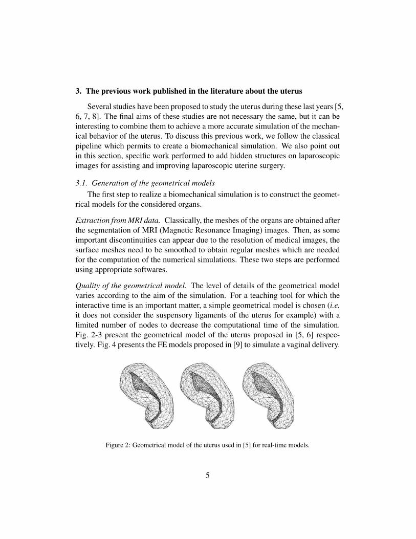
Quality of the geometrical model. The level of details of the geometrical modelvaries according to the aim of the simulation. For a teaching tool for which theinteractive time is an important matter, a simple geometrical model is chosen (i.e.it does not consider the suspensory ligaments of the uterus for example) with alimited number of nodes to decrease the computational time of the simulation.Fig. 2-3 present the geometrical model of the uterus proposed in [5, 6] respec-tively. Fig. 4 presents the FE models proposed in [9] to simulate a vaginal delivery.
4.3. Mechanical tissue properties
A typical set of loading-relaxation curves is shown in Fig. 3.Tissue samples were taken from different locations of the uterus(see legend). Again, an enormous variability manifests itself evenin samples which were taken from the same anatomical type oftissue.
4.4. Finite element model
A model of the uterus is shown in Fig. 4 exhibiting the stage atfull hydrometra. The pressure–cavum relation follows closely asample curve (Fig. 2, bottom). As mentioned above, the excessiveexecution time prevents the application of the model in a simulatorwhere real-time capabilities are required.
4.5. Extended statistical model
The left image in Fig. 5 presents an example uterine shapesynthesized with the discussed method. Deformations resultingfrom increasing hydrometra are shown to the right. Note that thesegeometries are not calculated but derived automatically with thestatistical model.
4.6. Visual representation
The triangular surfaces of the uterine cavity are the basis of theinteractive visualization. In order to increase the realism of the
Fig. 3. Exemplary stress-relaxation curves of various uterine samples tested inuniaxial compression as described in the text. Enormous variability was againfound. The ‘‘myoma’’ sample was recovered from a uterus exhibiting a large myoma.The constitutive parameters associated with a weakly compressible, non-linear,isotropic and viscoelastic law were determined by inverse FE fitting. The ‘‘myoma’’and ‘‘corpus’’ curves are located at the bottom and coincide with on of the ‘‘fundus’’curves. The figure is reproduced with permission from Weiss et al. [26].
Fig. 4. FE model of uterus with some 20,000 elements. Reduced variants (less degreesof freedom) were used in the development of the real-time models (Figs. 5 and 6).
Fig. 5. Triangle meshes synthesized with the extended statistical model. The uterinecavity is deformed according to increasing distension fluid pressures (left to right).
Fig. 6. Hydrometra deformation states as shown in the simulator, resulting from increasing pressure settings of the distension fluid (left to right).
P. Niederer et al. / European Journal of Obstetrics & Gynecology and Reproductive Biology 144S (2009) S90–S95S94
Figure 2: Geometrical model of the uterus used in [5] for real-time models.
5

Fig. 1. Left: Uterus with labeled vertices. Middle: Corresponding surface oftetrahedra mesh. Right: uterus with hydrometra. In all cases the frontal sur-face has been rendered in wireframe mode to visualize the inner cavity.
Fig. 2. Left: Visualization of the flow in the uterine cavity under limited pressure.Middle: Flow pathlines in a fully distended state. Right: Effect of additionalvortices on the flow field.
Fig. 3. Left: Low hydrometra in a cavity with a myoma. Middle: Same sceneunder maximal distension. Right: Scene with blood streams under the influenceof both inflow and vortices.
6 Conclusion and Future Work
In this paper we have presented the methods developed for the full simulationof hydrometra during hysteroscopy. Both the organ’s deformation and the fluidflow in the cavity are modeled with highest possible realism while still meetingthe real-time requirements of a simulator.
The fluid simulation will be further validated. We plan to perform an accurateflow simulation with exactly the same boundary conditions with an availablecommercial packages offline and quantitatively compare to our own results. Theincreased computational power of future hardware can be used to enhance the
Figure 3: Geometrical model of the uterus proposed in [6].
Figure 4: FE model of a vaginal delivery at different steps of the simulation. Images from [9].
For a simulation which focuses on the role of the different structures of thepelvic floor (in particular to investigate the role of the different structures on pelvicstatics dysfunctions), a more complete anatomical model including all the struc-tures is naturally requested. Fig. 5 presents the pelvic floor proposed in [10].
WIREs Systems Biology and Medicine Modeling childbirth
In this review, we first give a brief overviewof the history of childbirth studies, addressing thevarious techniques used to gain insights into thiscomplex process. We then discuss recent developmentsin computational models of childbirth, comparingthe results and the modeling frameworks. Lastly, wedescribe some of the main challenges in this field andpropose possible solutions for further improvements.
HISTORY OF CHILDBIRTH STUDIESThe mechanism of labor was first described by obste-tricians early in the eighteenth century, and much ofour understanding of the process is due to these earlypioneers. In particular, William Smellie (1697–1763)documented that the primary considerations for vagi-nal delivery were the size and shape of the pelvis andthe fetal head. He measured fetal skull diameters andpelvic diameters, and described the process of internalrotation of the fetal head. These were subsequentlypublished in a set of anatomical tables in 1793.17
Many of the early observations made by Smelliewere confirmed by Borell and Fernstrom in 1950sand 1960s in their published studies on childbirthand the mechanism of labor.18–22 By observing themovements of the fetal head with respect to thebony pelvis through a series of X-ray images,18–22
they suggested that the shape of the bony pelvishad the most influence on the motion of the fetalhead. In addition, they emphasized the importanceof the LA in the labor process. Their investigationsinitiated a new era in childbirth studies using imagingtechniques. However, such studies are unlikely to berepeated because of ethical restrictions.23
Ultrasound and MRI are the standard imagingmodalities in modern obstetrics and gynecology.5,24–27
They are considered superior to X-ray or computedtomography (CT), which expose subjects to harmfulradiation during the imaging process. Ultrasound ismore commonly employed because of its low cost,
portability, and ease of use. However, ultrasoundimages suffer from poor signal-to-noise ratio and sig-nificant geometric distortions, making this modalityless suitable for the creation of mathematical models.In contrast, MRI can be readily transformed into com-puter models for mechanical analysis (Figure 1).28–31
Such techniques have significantly enhanced therepresentation of pelvic floor structures. However,the limiting factor with MRI is the relatively lowspatial resolution, which fails to give a reasonablerepresentation of detailed pelvic floor structures suchas muscle fibers and connective tissues.
In order to address this issue, Janda et al.32
carried out a study on the morphological parametersof the pelvic floor using an embalmed female cadaver.The study quantified in detail the muscle fiber length,fiber directions, sarcomere length, and cross-sectionalarea. However, before these data can be used in anindividual-specific finite element (FE) model, someadjustments need to be applied to these descriptionsin order to compensate for the loss of muscle toneprior to the embalming process.
MODELS OF CHILDBIRTHWith the advance in computational technology, theability to study complex biomechanical processes,such as childbirth, can now be achieved on conven-tional commodity computers. Several research groupshave developed childbirth models in recent years.Table 1 provides a brief summary of their work withhighlights of their models.
First stage of laborThere have been very few studies involving compu-tational models of the first stage of labor. Early FEstudies investigated the material properties of thefetal head, and simulated fetal head deformation byapplying pressure boundary conditions.33–36 Lapeer
Vagina Rectum Uterus Perineal body
Bulbospongiosus
Transverse perineae
Bony pelvis
Obturator internusBladder Levator ani
Coccyx External anal sphincter
Internal anal sphincter
FIGURE 1 | Models of the female pelvic floor structures in anterior (left) and inferior (right) views.
Volume 2, Ju ly /August 2010 © 2009 John Wi ley & Sons, Inc. 461
Figure 5: The pelvic floor model presented in [10] to simulate vaginal delivery.
For a numerical simulation that only focuses on the uterus, we need a completegeometrical model of the uterus with a high number of nodes. Fig. 6 presents aFE model of the uterus proposed in [5]. It has 20,000 elements.
6

4.3. Mechanical tissue properties
A typical set of loading-relaxation curves is shown in Fig. 3.Tissue samples were taken from different locations of the uterus(see legend). Again, an enormous variability manifests itself evenin samples which were taken from the same anatomical type oftissue.
4.4. Finite element model
A model of the uterus is shown in Fig. 4 exhibiting the stage atfull hydrometra. The pressure–cavum relation follows closely asample curve (Fig. 2, bottom). As mentioned above, the excessiveexecution time prevents the application of the model in a simulatorwhere real-time capabilities are required.
4.5. Extended statistical model
The left image in Fig. 5 presents an example uterine shapesynthesized with the discussed method. Deformations resultingfrom increasing hydrometra are shown to the right. Note that thesegeometries are not calculated but derived automatically with thestatistical model.
4.6. Visual representation
The triangular surfaces of the uterine cavity are the basis of theinteractive visualization. In order to increase the realism of the
Fig. 3. Exemplary stress-relaxation curves of various uterine samples tested inuniaxial compression as described in the text. Enormous variability was againfound. The ‘‘myoma’’ sample was recovered from a uterus exhibiting a large myoma.The constitutive parameters associated with a weakly compressible, non-linear,isotropic and viscoelastic law were determined by inverse FE fitting. The ‘‘myoma’’and ‘‘corpus’’ curves are located at the bottom and coincide with on of the ‘‘fundus’’curves. The figure is reproduced with permission from Weiss et al. [26].
Fig. 4. FE model of uterus with some 20,000 elements. Reduced variants (less degreesof freedom) were used in the development of the real-time models (Figs. 5 and 6).
Fig. 5. Triangle meshes synthesized with the extended statistical model. The uterinecavity is deformed according to increasing distension fluid pressures (left to right).
Fig. 6. Hydrometra deformation states as shown in the simulator, resulting from increasing pressure settings of the distension fluid (left to right).
P. Niederer et al. / European Journal of Obstetrics & Gynecology and Reproductive Biology 144S (2009) S90–S95S94
Figure 6: FE model of the uterus with 20,000 elements. It has been proposed in [5].
Manual reconstruction. The segmentation of the MRI data is still difficult for thepelvic system and it remains hard to extract all the details such as the ligamentsconnected to the uterus. In this case, the partial segmentations obtained fromMRI data have to be completed using a manual reconstruction [11]. This step isperformed according to anatomical descriptions. It concerns the vagina, the pelvicfloor, floor muscles, ligaments (with some difficulties for some ligaments wherethere is no consensus) and the cervix (according to the considering dilatation stepin the case of the realization of a childbirth simulation).
Variable anatomical models. The use of solid models to generate geometricalmeshes facilitates the addition of elements (like ligaments) into these models. Thisis an important issue when all the structures are not visible in the medical images,or when we want to adjust the models according to educational criteria for a train-ing simulator, or to better understand the role of each structure of the female pelvicsystem (which is illustrated in Fig. 1). For example, House [7] constructed geo-metrical models of the uterine fundus and cervix (which are presented in Fig. 7)to understand the deformation mechanisms which lead to cervical shortening dur-ing pregnancy. The construction of the geometrical models was performed in twosteps. Firstly, solid models have been generated from MRI data using a solid mod-eling software. Secondly, the numerical models (appropriate for the simulation)have been generated by exporting the solid models in a finite element software. A3D ultrasound technique applied on pregnant volunteer patients was also used toobtain imaging volumes.
7

were used. By combining MRI and 3D ultrasounddata, we developed anatomical models with goodcorrelation to in 3D anatomy in vivo.
Clearly, cervical shortening is a complex functionof tissue properties, loading conditions, and anatomi-cal geometry. Less clear is how a short cervix relatesto the pathogenesis of preterm birth. In patientswith cervical insufficiency, a short cervix likelyrelates to weakened tissue properties of the cervicalstroma. However, in the setting of placental abrupt-ion (Weiner et al., 2005) or intrauterine infection(Vaisbuch et al., 2010), a short cervix is caused by apathology unrelated to cervical tissue. Many patientsshow elements of multiple pathologies and discover-ing the cause of preterm birth in these patients ischallenging. There is a strong need in the field toclarify how cervical shortening relates to pathogene-sis of preterm birth. This need prompted the studiesdiscussed in this review.
A novel feature of the current studies is the gener-ation of anatomically accurate numerical modelsfrom ultrasound imaging during pregnancy. Therewere significant challenges in converting ultrasounddata to numerical models. Ultrasound data are com-plicated by multiple artifacts such as unclear boun-daries, signal attenuation, speckle, shadows, anddropout (Nobel and Boukerroui, 2006). Automaticmethods for selecting the anatomy of interest fromthe image were not successful. Clinical experience
was essential to detect the anatomy of interest. Themost significant limitation of our approach was itrequired several days to convert ultrasound data intoa usable numerical model.
Through a combination of in vivo imaging,mechanical characterization of cervical tissue andnumerical simulation, we examined the key factorsthat affect the cervical function and dysfunction dur-ing pregnancy. An improved understanding of thesefactors will aid efforts to develop rational therapiesthat aim to improve cervical function and delaypreterm birth.
REFERENCES
Institute of Medicine. 2006. Preterm Birth: Causes, Consequences,and Prevention. Washington D.C.: National Academies Press.
Fonseca EB, Celik E, Parra M, Singh M, Nicolaides KH; Fetal Medi-cine Foundation: Second Trimester Screening Group. 2007. Pro-gesterone and the risk of preterm birth among women with ashort cervix. N Engl J Med 357:462–469.
Goya M, Pratcorona L, Merced C, Rodo C, Valle L, Romero A, JuanM, Rodriguez A, Munoz B, Santacruz B, Bello-Munoz JC, LlurbaE, Higueras T, Cabero L, Carreras E; Pesario Cervical para EvitarPrematuridad (PECEP) Trial Group. 2012. Cervical pessary inpregnant women with a short cervix (PECEP): An open-labelrandomised controlled trial. Lancet 379:1800–1806.
Hassan SS, Romero R, Vidyadhari D, Fusey S, Baxter JK, Khan-delwal M, Vijayaraghavan J, Trivedi Y, Soma-Pillay P, Sambarey
Fig. 4. Numerical simulations of cervical function. The top simulation captures the well-known progression(TYVU) of cervical funneling. The middle row shows uterine growth from 22 weeks (green) to 36 weeks (pink) asseen on MRI. The simulation is able to capture both the increase in uterine size but also the development of thelower uterine segment. In the bottom row, the ultrasound response to fundal pressure is compared to a simulatedresponse. Note that only when the correct properties of the cervix are used is the simulation able to capture theanatomical changes seen on ultrasound. This technique gives an estimate of the tissue properties of the cervix invivo. [Color figure can be viewed in the online issue, which is available at wileyonlinelibrary.com.]
103Three-dimensional Anatomy of the Cervix During Pregnancy
Figure 7: FE models proposed in [7] for numerical simulations of cervical function.
In the context of the development of a medical training simulator, an otherchallenge is to propose a wide variety of scenarios. These scenarios are basedon models for healthy organs or pathological organs. For this purpose, in orderto realize a training hysteroscopic simulator (which permits to visualize the innersurface of the uterus), Sierra presented a framework to generate variable modelsof the uterus anatomy [12, 13]. The method was based on a statistical description.The parameters of the geometrical model of the uterus concerned for example thedimension of the fundus, the dimension of the cervix and the length of the corpus(see Fig. 8). This work was completed by a method to generate pathologies foundin the uterine cavity (such as leiomyomas and polyps) and a method to incorporatethese pathologies into the model of the healthy uterus [14, 15].
5. Results and discussion
Based on the method described above, an interactivetool has been developed for the intuitive derivation ofnew instances of the uterus. Fig. 2 depicts the GUI of thetool based on the statistical analysis of the database, pre-senting the mean shape and the widget with seven sliders.The user can now manually adjust each slider indepen-dently to modify the value of the corresponding predictor.Along with each slider two values are presented, first thespecified and second the measured length of the predictor.These values will only diverge if the algorithm is not able togenerate a uterus based on the given predictors, in whichcase the last generated shape is kept. The range of possiblevalues can be set independently for each predictor througha configuration file. The Newton–Raphson optimization isa second order scheme and thus converges relatively fast,i.e., the number of correct digits is doubled in every itera-tion. In general, for the present implementation less thansix iterations are required. Hence, new shapes can be eval-uated in real time as the user moves the sliders. Even theunderlying statistical analysis including the transformationof the shapes into a common coordinate system, which isperformed offline as a preprocessing step, can be computedin a few seconds on a standard 3 GHz PC.
The variation of the mean shape induced by the ‘fundusdepth’ predictor is illustrated in the upper row in Fig. 3.The values for the presented images range from 26 to49 mm, covering about 1.5 times the standard deviationfound in the present database. The measured values forall other predictors, i.e., the distances between the otherlandmarks, did not change after the deformation, as
requested. The lower row of Fig. 3 depicts uteri with vary-ing the overall length ranging from 57 to 75 mm. Obvi-ously, the flexion of the uterus cannot be extendedfurther. The uterus length would exceed the sum of fundusand cervix length, an impossible constraint that preventsthe convergence of the Newton–Raphson algorithm.
As the shapes were not normalized to a standard size, alldatasets can be integrated into one common database todirectly predict new instances based on the providedparameters. While size normalization could in principleimprove the prediction of the shapes, we observed no qual-itative difference for the given uteri. The ‘cervix width’ and‘fundus width’ predictors are most sensitive to perturba-tions. Larger changes of these values would make theadjustment of the remaining predictors also necessary toavoid unnatural shapes. These findings may indicate thatthe width is correlated to the remaining predictors. How-ever, it has to be noted that the segmentation of the lateralwalls of the uterus is relatively difficult and error prone, asthe arteria uterina follows exactly this landmark andstrongly blurs the MRI scans. It is therefore not trivial toassign the different behavior of the predictors to a singlesource. To assess the results of the presented framework,a systematic analysis of the prediction performance hasbeen carried out.
In the following, three properties of the statistical frame-work are discussed (Davies, 2002). First, the model shouldbe able to represent unseen instances of the object class.i.e., it should generalize the main characteristics of theshapes based on the given set of objects. Second, the com-pactness of the model can be assessed, i.e., its ability to rep-resent an object by as few parameters as possible. Third,
Fig. 2. Graphical user interface for derivation of new uteri based on seven predictors.
Fig. 3. Upper row: variation of the uterus for different values of the ‘fundus depth’ predictor. Lower row: different cervix–fundus angles induced by thevariation of the overall uterine length predictor.
280 R. Sierra et al. / Medical Image Analysis 10 (2006) 275–285
Figure 8: Generation of variable anatomical models proposed in [13].
3.2. Study of the uterus in laparoscopic imagesIn recent years, searchers have developed software for assisting and improv-
ing laparoscopic uterine surgery [16, 17, 18, 19]. The goal is to provide real-timeAugmented Reality (AR), which allows the surgeon to see where important hidden
8

structures are located, such as the uterine canal, major blood vessels and myomas(see Fig. 9). This works by aligning (or registering) a pre-operative radiologi-cal image such as MRI or CT with the real-time laparoscopic video. Once done,anatomical structures from the pre-operative image are overlaid with the laparo-scopic video in real-time. Currently AR has been developed for the treatment ofmyomas (also called uterine fibroids) using pre-operative T2 weighted MRI im-ages [17]. A preliminary study of the clinical impact was published in [20]. Toachieve this AR, three technical challenges were solved.
����
����
����
��� �� �� ���� �� ���� �� ����� ��
� ����������� ����
��� ������� �� ��� ������� ��
��� ������� �������
Figure 9: (a) Registration error vs. number of views. (b) Number of iterations vs. number of views. (c) Mean surface registration error for 2,4 and15 views.
Figure 10: Registration between the uterus in a pre-operative MRI to intra-operative laparoscopic images, and visual augmentation of two hiddenmyomas. The top row shows M (the mesh model of the uterus from the MRI ) overlaid in each image. The red contours denote the silhouetteboundaries of M in each image. The bottom row shows the augmented myomas. Best Viewed in colour.
complementary cues involving natural anatomical landmarks, theuterus’ boundary contour and feature correspondences.
This is the first work which registers a pre-operative MRI of theuterus to laparoscopic images. In our ongoing research we will per-form a deeper quantitative evaluation, test other deformable models,and test the system’s performance on live videos. Our solution isnot limited to visualising myomas. Any anatomical structure thatis visible in the MRI can be visualised in the laparoscopic images,such as the cervix and uterine cavity. We expect that augmentingthis information may also help the surgeon perform myomectomiesand other uterine surgery, improve safety and reduce time in theoperating room.
REFERENCES
[1] AgiSoft LLC. PhotoScan, http://www.agisoft.ru/products/photoscan.[2] H. O. Altamar, R. E. Ong, C. L. Glisson, D. P. Viprakasit, M. I. Miga,
S. D. Herrell, and R. L. Galloway. Kidney deformation and intrapro-cedural registration: A study of elements of image-guided kidneysurgery. Endourology, 2010.
[3] A. Amir-Khalili, M. S. Nosrati, J.-M. Peyrat, G. Hamarneh, andR. Abugharbieh. Uncertainty-encoded augmented reality for robot-assisted partial nephrectomy: A phantom study. In AECAI@MICCAI,2013.
[4] A. Bartoli, T. Collins, N. Bourdel, and M. Canis. Computer assistedminimally invasive surgery: Is medical computer vision the answer toimproving laparosurgery? Medical Hypotheses, 2012.
[5] D. Cohen, E. Mayer, D. Chen, A. Anstee, J. Vale, G.-Z. Yang,A. Darzi, and P. J. Edwards. Augmented reality image guidance inminimally invasive prostatectomy. In Prostate Cancer Imaging, pages101–110, 2010.
[6] T. Collins, D. Pizarro, A. Bartoli, M. Canis, and N. Bourdel. Realtimewide-baseline registration of the uterus in laparoscopic videos usingmultiple texture maps. In MIAR@MICCAI. 2013.
[7] M. Garland and P. S. Heckbert. Surface simplification using quadricerror metrics. In SIGGRAPH, 1997.
[8] G. Hamarneh, A. Amir-Khalili, M. Nosrati, I. Figueroa, J. Kawa-hara, O. Al-Alao, J.-M. Peyrat, J. Abi-Nahed, A. Al-Ansari, andR. Abugharbieh. Towards multi-modal image-guided tumour iden-tification in robot-assisted partial nephrectomy. In MECBME, 2014.
[9] N. Haouchine, J. Dequidt, I. Peterlık, E. Kerrien, M.-O. Berger, andS. Cotin. Image-guided simulation of heterogeneous tissue deforma-tion for augmented reality during hepatic surgery. In ISMAR, 2013.
[10] S. Ilic, M. Salzmann, and P. Fua. Implicit meshes for effective silhou-ette handling. International Journal of Computer Vision, 2006.
[11] E. Kruijff, J. E. Swan, and S. Feiner. Perceptual issues in augmentedreality revisited. In ISMAR, 2010.
[12] T. Mertzanidou, J. H. Hipwell, M. J. Cardoso, X. Zhang, C. Tan-ner, S. Ourselin, U. Bick, H. J. Huisman, N. Karssemeijer, and D. J.Hawkes. MRI to X-ray mammography registration using a volume-preserving affine transformation. Medical Image Analysis, 2012.
[13] D. J. Mirota, M. Ishii, and G. D. Hager. Vision-based navigation inimage-guided interventions. Annual Review of Biomedical Engineer-ing, 13, 2011.
[14] G. Pearsall and V. Roberts. Passive mechanical properties of uterinemuscle (myometrium) tested in vitro. Journal of Biomechanics, 1978.
[15] G. Puerto-Souza, J. A. Cadeddu, and G. Mariottini. Toward long-termand accurate augmented-reality for monocular endoscopic videos.Biomedical Engineering, 2014.
[16] T. Simpfendorfer, M. Baumhauer, M. Muller, C. N. Gutt, H.-P.Meinzer, J. J. Rassweiler, S. Guven, and D. Teber. Augmented realityvisualization during laparoscopic radical prostatectomy. Endourology,25(12):1841–1845, 2011.
[17] D. Stoyanov, M. V. Scarzanella, P. Pratt, and G.-Z. Yang. Real-time stereo reconstruction in robotically assisted minimally invasivesurgery. In MICCAI, pages 275–282, 2010.
[18] L.-M. Su, B. P. Vagvolgyi, R. Agarwal, C. E. Reiley, R. H. Taylor, andG. D. Hager. Augmented reality during robot-assisted laparoscopicpartial nephrectomy: toward real-time 3D-CT to stereoscopic videoregistration. Urology, 73(4):896–900, 2009.
[19] I. Wolf, M. Vetter, I. Wegner, M. Nolden, T. Bottger, M. Hastenteufel,M. Schobinger, T. Kunert, and H.-P. Meinzer. The medical imaginginteraction toolkit (MITK), http://www.mitk.org/.
Figure 9: Registration between the uterus in a pre-operative MRI to intra-operative laparoscopicimages (top), and visual augmentation (bottom) of two hidden myomas. Images from [17].
Reconstruction of the 3D model. The first challenge is to reconstruct a 3D modelof the uterus and myomas from the MRI data (commonly known as segmentationor delineation). Because the pre-operative image is taken before surgery (typicallyseveral weeks before), this process does not need to be solved in real-time, andwas performed semi-automatically with the aid of a human operator using open-source segmentation software [21].
Initial registration. The second challenge is to determine the change of shape ofthe uterus between the uterus in the pre-operative image and at the start of surgery(referred to as the initial registration). This is necessary to correctly register thepre-operative models with the laparoscopic video to account for soft-tissue defor-mation. For non-pregnant patients, soft-tissue deformation is caused by a numberof factors including the patient’s lying position and rate of abdominal insufflation.The initial registration was solved as follows. We record a short laparoscopicvideo of the uterus from different angles (the exploratory video), by having a sur-gical assistant move the uterus with a cannula. From the exploratory video, the
9

3D shape of the uterus was reconstructed using a process called Structure-from-Motion. The registration was achieved using three complementary visual cues.The first cue was the 3D reconstruction: specifically, that the surface of the visibleregion of the pre-operative uterus model should align closely to the 3D reconstruc-tion. The second cue was manually-annotated registration landmarks. A ”registra-tion landmark” is a point on the uterus that can be found in both the pre-operativeMRI and the laparoscopic images. The junctions between the Fallopian tubes andthe fundus were used, as these could be clearly found in both modalities. The thirdcue was the boundary contours of the uterus. Specifically, the uterus’ boundarywas manually annotated in the exploratory video, and the registration was madeto align the pre-operative model’s boundaries with the manually-annotated bound-aries. Registration was achieved with a so-called energy minimisation approach.This involves encoding the registration cues as energy terms, and numericallyminimizing the energy to obtain the correct registration. To achieve this, a modelof deformation must be used. Here an approximate model was used (a 3D affinemodel), which is not a complex deformation model. However, a compromise hadto be made between using a more complex model and being able to determinethe model’s parameters. The affine model was shown to provide a good approx-imation and its parameters could be determined reliably. Note that research hascontinued to make the initial registration fully automatic. In [19] a method toautomatically detect the uterus and the Fallopian tube junctions in laparoscopicimages was proposed. In [18] a method to automatically segment the uterus in la-paroscopic images was proposed. The segmentation gives the boundary contoursof the uterus, which saves considerable time for a human annotator.
Alignment of the pre-operative images with the laparoscopic video. The thirdtechnical challenge to achieve AR is to update the initial registration for eachnew laparoscopic image and to overlay the myomas onto the laparoscopic image.Unlike the first and second challenges, this one needs to be real-time. A simpli-fying assumption was made, which was that the update could be modeled with a3D rigid transform. This transform can account for changes of the laparoscopesposition and global changes of the uterus’ position, but it cannot account for sig-nificant soft tissue deformation. This was acceptable by instructing the surgeonsto not significantly deform the uterus with surgical tools whilst AR was active. Arobust, automatic solution was found that worked reliably for long durations (5minutes or more) [16]. This operated at approximately 20 frames per second ona standard workstation PC and could handle occlusions from instruments and theuterus going out of the field-of-view. For each laparoscopic image, the registration
10

was used to give the 3D position of the myomas in the laparoscopes field-of-view.The myomas surfaces were then rendered from the laparoscope’s viewpoint, andthe render was blended with the real laparoscopic image. The blend was done togive the impression that the uterus was semi-transparent and the myomas couldbe seen inside. Fig. 10 presents the registered models obtained in [16].
does not correspond to anything physical, but rather the region on the uterusfor which SfM could reconstruct shape.
U
U
U
Fig. 3: Column 1: the dense 3D models built in Phase 1. Column 2: thecoagulation markers. Columns 3&4: the registered models using WBMTR.
5 Conclusion and Future Work
We have presented a reliable and fast way to register the uterus in monocularlaparoscopy using a novel two-phase approach. The approach di↵ers to SLAMby decoupling 3D mapping and segmentation (done in Phase 1) from liveregistration (done in Phase 2). Phase 2 is achieved in realtime at approximately26fps using standard hardware, and does not depend on successful registrationin previous frames. It is thus simpler than EKF-SLAM and PTAM because itdoes not require switching between tracking and re-localisation. We have shownthat our approach significantly outperforms EKF-SLAM for this problem. Inthe future we aim to enlarge our evaluation dataset and to explore the newopportunities that our method opens up for AR-assisted resection planning inuterine laparosurgery.
References
1. Agisoft: Photoscan, http://www.agisoft.ru/products/photoscan2. Bay, H., Ess, A., Tuytelaars, T., Van Gool, L.: Speeded-up robust features (SURF).
Comput. Vis. Image Underst. 110(3) (Jun 2008)3. Collins, T., Bartoli, A.: Towards live monocular 3D laparoscopy using shading and
specularity information. In: IPCAI. pp. 11–21 (2012)4. Davison, A.J., Reid, I.D., Molton, N.D., Stasse, O.: MonoSLAM: Real-time single
camera SLAM. PAMI 29(6), 1052–1067 (2007)5. Fischler, M.A., Bolles, R.C.: Random sample consensus. Commun. ACM (1981)6. Grasa, O.G., Civera, J., Guemes, A., Muoz, V., Montiel, J.M.M.: EKF monocular
SLAM 3D modeling, measuring and augmented reality from endoscope imagesequences. In: AEMI-ARCAI (2009)
7. Grasa, O.G., Civera, J., Montiel, J.M.M.: EKF monocular SLAM withrelocalization for laparoscopic sequences. In: ICRA (2011)
Figure 10: The registered models obtained using WBMTR (Wide-Baseline Multi-TexturemapRegistration). Images from [16].
The several techniques proposed in these papers may be used in the context ofMRI data of pregnant patients to improve the extraction and the reconstruction ofthe uterus and the others tissues around it.
3.3. Assessment of the biomechanical properties of the uterusTo simulate the mechanical behavior of an organ, we also have to perform
some experiments in vivo or in vitro on the tissues to determine its stress-strainrelationship, that is a specific force per unit area (stress) versus a specific dis-placement from initial length (strain). This relation is the constitutive law of theorgan. It characterizes the mechanical behavior of the deformable object. Thismechanical behavior can be linear, non linear, isotropic, anisotropic, heteroge-neous, viscoelastic or viscoplastic. We also need to determine the mechanicalparameters associated to the constitutive law. Their exact values are extremelydifficult to determine and they may vary by one or several order of magnitude,depending on the protocol used for their estimation. Moreover, the values ob-tained in vitro are usually inappropriate, and it is often difficult to perform theexperiments in vivo.
Several techniques to perform the measurements. In 2014, Mazza [8] presenteda review on research made to characterize the biomechanical and microstructuralproperties of the cervix during pregnancy. This kind of research is made in orderto prevent preterm delivery, with an established correlation between the stiffnessof the cervix and the risk of preterm delivery. Three methods were privileged forthese measurements. The first method, called elastography, consists to assess thedeformation of the organ by measuring its displacement when a force is applied
11

on it. The corresponding displacement of the organ is quantified by tracking theposition of a large number of points of the organ during the motion. We obtain anelastogram corresponding to a color map indicating the difference between soft re-gions (i.e. with large displacements of the points) and hard regions (i.e. with verysmall displacements of the points) of the deformed organ. The second methodconsists to compress the tissue using ultrasound until no further deformation canbe observed to determine its ”maximum deformability”. The third method con-sists to use an aspiration device to determine in vivo the stress-strain curve of thetissue.
Impact of the protocol used. In 2008, Myers [22] proposed a study to establisha stringent protocol to collect data in order to measure the mechanical proper-ties of cervical tissue under different loading modes (for example, in tension,confined compression, unconfined compression). The study was performed fornon-pregnant and pregnant patients. To briefly sum up, a non linear behavior wasobserved for the cervical stroma. Moreover, one of the interest of this paper is todraw attention on the large discrepancies in the results presented in the literature.Thus, a lot of precautions are necessary to ensure the repeatability of the measure-ments performed on a tissue to obtain useful values for the numerical simulationand to characterize with accuracy the mechanical properties of the tissue.
Results obtained from an aspiration device. In 2006, Mazza [23] presented astudy performed with an aspiration device to characterize the mechanical prop-erties of the human uterine cervix in vivo. The average values of the stiffness pa-rameter vary from 0.095 to 0.24 bar/mm. The experiments have been performedon eight patients, aged from 47 to 69 years and having had 1 to 4 births. Asduring the pregnancy, the uterus undergoes significant changes [24], Bauer [25]presented another study in 2009 performed with the same device but on pregnantwomen (between 21 and 36 weeks’ gestation). Stiffness values varied between0.013 and 0.068 bar/mm. We can note that the tissue of non-pregnant patient issignificantly stiffer than tissue of pregnant women. These results remained thesame for both tension and compression experiments. In 2013, Badir [26] pre-sented a novel procedure for the realization of measurement on the cervix duringgestation. This procedure was also based on the pipette aspiration technique. Asthe measurement is fast and it does not caused any pain, it can be used as routinecontrol during the pregnancy. Thus, it permits to obtain a large amount of mea-surements and it permits to follow the evolution of the biomechanical propertiesduring the gestation.
12

To sum up, a lot of studies have been performed on the cervix biomechanicalproperties. Obviously, this part of the uterus was studied because of the estimatedrelation between cervical stiffness and the risk of preterm. The technics and pro-tocols of measurement used are more and more precise and aim to ensure therepeatability of the measurements. But it seems still difficult to assess with highaccuracy the biomechanical properties of the tissues. Indeed, the measurementsnaturally depend on many parameters such as localization of the assessment, de-gree of cervix lubrification, type of protocol used to move the tissue (mainly byapplying a force on it), maternal age, number of pregnancies, or term of pregnan-cies.
3.4. The Finite Element models proposed to simulate the behavior of the uterusOnce the geometrical models of the organs created and their mechanical prop-
erties studied, we can create the corresponding physical model in order to performthe numerical simulation. This physical model is more or less complex accord-ing to the aim of the numerical simulation. To achieve an accurate simulation,a Finite Element model is generally chosen with a constitutive law in agreementwith that of the organ (classically hyper-elastic and anisotropic for tissues). Toreduce the computational time, a simpler law can be selected but at the expense ofprecision. We also have to define the boundary conditions of the organs involvedin the simulation as well as their interactions.
Electrophysiological and molecular mechanism of uterus. Sharp [27] proposed areview on the computer models published to study the uterine activation duringlabor. The models were divided in three categories: (i) models of uterine electro-physiology and propagation, (ii) models of the molecular mechanisms that initiatethe labor, (iii) and biomechanical models of labor. Then, the review focused onlyon electrophysiological and molecular mechanisms activating labor. This kind ofresearch seems distant from work on biomechanics models but it can be interest-ing to follow the results obtained with this approach.
Modeling of the uterine pressure. In 2010, Li [28] proposed a review on finiteelement models developed to simulate mechanics of vaginal delivery. The de-scribed models concerned in particular the modeling of the pelvic floor (includingthe levator ani muscles) and the fetal head. The aim is to be able to simulate boththe deformation of the head and the pelvic floor. The most challenging aspect ofchildbirth modeling is to take into account all the forces applied on the organs: theexpelling forces induced by the uterus and the abdominal muscles Those forces
13
were approximated by applying kinematic boundary constraints on the fetal head.This strategy avoids to explicitly simulate the complex mechanism of the uteruswhich is not the primary aim of those simulations.
Finite Element models of a pregnant woman. Some papers focused on the mod-eling of the pregnant woman to study injury mechanisms in car crashes [29, 30].The aim is to propose a specific safety system to decrease the risk of fetal loss.A simulation based on a Finite Element model was performed. The geometricalmodel of the uterus was extracted from MRI data of a pregnant woman at ninemonth of pregnancy. Then, the gravid uterus has been incorporated into the HU-MOS (HUman MOdel For Safety) model which is a Finite Element model of acomplete human body in driving position. The mechanical behavior of the uteruswas modeled as a hyper-elastic Ogden material and the amniotic fluid was repre-sented using a Euler model. Thus, the anisotropic behavior of the uterus was notconsidered in this study. For the validation of the simulations, the PMHS (PostMortem Human Subjects) approach has been improved by inserting an artificialuterus made in silicon into a woman body. Four belt loading tests were real-ized and compared to the numerical response of the model in similar conditions.Preliminary results obtained were in agreement with the experimental curves. Inthese tests of car crash, the uterus did not sustain high strain.
Recently, a biomechanical model of the pregnant pelvic system has been pro-posed in [11]. The aim was to study the constraints applied on the pelvic com-ponents during childbirth to improve the knowledge about uterine prolapse. Thepelvic system proposed (see Fig. 11) included the muscles, ligaments and pelvicorgans. The geometrical models have been constructed from MRI data with amanual reconstruction of non visible structures. These manual reconstructionshave been made according to anatomical descriptions. The ligaments were alsoadded to the geometrical models with some difficulties for ones for which no con-sensus is established. Moreover, several models of the fetal head and uterus havebeen used to simulate the vaginal delivery. Thus, the volume of the geometricalmodels have been changed in order to measure their corresponding impacts on theligaments. The properties of the tissues were based on previous work performedby the same team [31, 32, 33, 34] and the tissues were modeled with an elasticlinear behavior using the shell finite elements. As boundary conditions, the pelvicbone and uterine fundus were fixed; the muscle floor was fixed to the pelvic bone.Then, the simulation of childbirth was performed by imposing a trajectory of thefetal head during its descent. The simulations enabled to measure the deforma-tion of the uterosacral ligaments during the vaginal delivery. Some improvements
14

have to be made in order to consider the hyper-elastic and anisotropic behavior ofthe tissues. Nevertheless, we can note that this pregnant pelvic system is the mostcomplete proposed in the literature. Thus, we can hope that, once the improve-ments performed, this pelvic system (which includes the ligaments connecting theuterus to the pelvis) could improve our knowledge of damages sustained during avaginal delivery.
textbooks [5]. Figure 3 shows the main steps of this trajectory,imposed in the most frequent variety (left anterior occipito-iliac engagement, occipito-pubic expulsion). Simulationswere realised with the finite elements software “SOFA” de-veloped by INRIA and largely used for biomedical simula-tions [20]. Simulations were done with varying the size of thefetal head.
Results
We obtained a pelvic model of the pregnant woman at termwhich allows us to simulate delivery. Figure 4 shows thepelvic system at different steps of the fetal head descent(engagement, deflexion, expulsion) and the range of associat-ed displacements. Displacement is maximal on the pelvicfloor muscle, vagina and uterosacral ligaments.
It becomes possible to evaluate the potentially damagedareas during childbirth, and especially the potential damage ofthe suspension system. Placed as they are, round and largeligaments mainly suffer compression and will not be dam-aged. But uterosacral ligaments will be submitted to tractionwhen the head reaches the inferior uterine segment. For amedium-sized fetal head (50th percentile for 41 WA),uterosacral ligaments undergo a deformation near 30 %(Fig. 5).
This first modelling shows the displacements of uterosacralligaments whose important role in pelvic statics is well known[10]. It becomes possible to vary the delivery scenario, simu-lating different situations, function of gestational age or fetaltrophicity, by varying volumes of fetal head and uterus andanalysing potential damages in those cases. Figure 5, forexample, shows the deformation of the uterosacral ligamentswhen the head is inferior to the 10th percentile in the case ofpremature birth or fetal hypotrophy at 41 WA.
Pelvic tissues have a visco-hyperelastic behaviour and canbe damaged. In 2008, Rubod et al. showed the strain–stresscurves realised by cyclic trials with deformations at growinglevels. Behaviour of the pelvic soft tissues is, classically, oneof a synthetic elastomeric material and shows that the damagevaries with the maximal deformation of the tissue. When thesize of the fetal head grows, more distortion is generated inuterosacral ligaments and therefore potentially causing greaterdamage that may alter pelvic statics.We did not at this stage ofthe study assess quantitative damage of delivery on the pelvicfloor muscle (levator ani) and on the vagina.
Discussion
Recapitulation of results
We wanted to study the constraints and deformations of pelvicstructures during childbirth to evaluate the risk of urogenitalprolapse. We built an anatomical and functional model of thepelvic system of the pregnant woman. We had to deal withmany numerical challenges to successfully realise a first real-istic passage of the fetal head through the system “uterus-vagina-pelvic floor”. Uterosacral ligaments are submitted toan important traction during the passage of the fetal head atthe lower uterine segment, and their deformation is important,around 30 %. Previous research of our team on functional
Fig. 2 Complete geometric model of pelvic system of the pregnantwoman
Table 1 Mechanical properties of pelvic tissues of the nonpregnantwoman already determined by our team [10] were adapted to pregnancyusing literature data [18, 19]
Object Young’s modulus (MPa) Thickness ordiameter (mm)
Nonpregnant Pregnant
Rectum 0.54 0.09 3
Vagina 0.67 0.11 4
Bladder 0.24 0.04 3
Uterosacral ligament 0.78 0.13 8
Round ligament 1.32 0.22 4
Large ligament 1.32 0.22 4
Muscle floora 0.4 0.06 10
Uterusa 1.5 0.25 30
aQualitative data
Int Urogynecol J
Figure 11: The geometrical model of pelvic system (proposed in [11]) of a pregnant woman.
Finite Element models of the uterus. In 1975, Mizrahi and Karni [1] have pre-sented a mechanical model of the uterus. As the thickness of the uterus is small incomparison to its two others dimensions, they modeled the uterus as a thin closedshell. They also treated the constraints involved by the ligaments attachments andthe cervix. For the definition of the shell model, they considered that the uterinemuscle has no rigidity in bending and that the single stiffener is the cervix actingas a tensile anchoring ring. Moreover, the displacements of the cervix have beenput to zero for a single contraction and constant during the second stage of la-bor when the cervix is fully dilated. They also assumed that the volume boundedby the uterus is constant during the deformation due to the incompressibility ofthe inter-uterine fluid. In [2], they presented a study to improve the anisotropicbehavior of the uterine muscle. It is difficult to evaluate the results obtained asthere is no comparison between the results obtained by simulations and real invivo experimentations.
More recently, an other Finite Element model (FEM) of the uterus was pro-posed in [3] to reproduce realistic mechanical and physiologic behaviors of hys-teroscopy. The corresponding surgical procedure consists to distend the uterus
15

with the accumulation of watery fluid in order to easily access and to well visual-ize the uterine cavity and faloppian tube. The volumetric mesh used for the hys-teroscopic simulations was composed of tetrahedra with a total of 56,000 nodes.The mechanical behavior defined was based on a polynomial strain-energy func-tion proposed by Kauer [35]. Moreover, as boundary conditions, the cervix wasfixed at the beginning of the hysteroscopy. Then, a pressure of 20 kPa was appliedinto the uterine cavity. But due to a lack of experimental data, it was difficult toprove the accuracy of the model for various loading situations. We can note thatthese simulations required about 17 hours of CPU time.
Real-time simulations of the uterus. Some work focused on the implementationof mechanical models of the uterus that run in real-time [36, 37, 38, 12, 6, 5]. Theidea is to propose training simulators for hysteroscopic or laparoscopic surgery.The challenge is to make adequate simplifications of mechanical models to de-velop pertinent simulators reproducing realistic simulations. In this context ofreal-time simulation, the accurate FEM proposed in [3] was combined to a Free-Forme Deformation (FFD) technique [6]. The idea is to register accurate re-sponses of the tissue model to different fluid pressures in order to use these resultsduring the real-time simulation. For this, some hypothesis were made to simplifythe model: the interactions made on the uterus with the simulator were restrictedto the fundus of the uterus; the boundary conditions of the uterus did not changeduring the intervention; the cavity of the uterus should not endure extreme mod-ifications (i.e. the topology of the uterus was supposed not to change). Thus,the FEM [3] was first executed as precomputations. Then, during the use of thesimulator, the results of the FEM simulation were loaded and used to compute inreal-time the response of the tissue according to the interaction applied. For thispurpose, a simple linear interpolation was performed to compute the new posi-tions of the mesh. Furthermore, a fluid simulation (based on the Navier-Stokesequations) was also performed to simulate the fluid flow in the cavity in order toincrease the simulator realism. In future work, the authors will plan to use theGPU to simulate the fluid with an higher accuracy. Moreover, the FEM simula-tion used for the computations will be improved to simulate the non-linear andanisotropic behavior of the myometrium.
4. Our childbirth simulation in real-time
Our work focused on a childbirth simulator for training of medical gesturesduring vaginal delivery. In this context, we proposed a biomechanical simulation
16

of the descent of the fetus during the second step of the labor. The challenge was toobtain a real-time simulation. This was achieved by making a lot of simplificationsin the modeling of each organ involved, since it is not possible to combine anaccurate simulation of each organ. Thus, our aim was to obtain a realist trajectoryof the fetus induced by the interaction of each organ despite their simplifications.All the details of this work can be found in [9].
The simulation was composed of the fetus, uterus, pelvis and abdomen of theparturient woman. During the childbirth process, the uterus is one of the mostimportant organs of the pelvic system since it supports all the efforts applied byothers organs. Thus, the uterine contractions associated to the voluntary efforts ofthe parturient woman induce a pressure on the fetus, pushing it into the birth canal.Throughout the descent of the fetus, the inner walls of the uterus are flattenedagainst the fetal body, decreasing the uterine volume progressively. The heightof the uterus at the end of the childbirth process is approximately one third of itsheight before the beginning of the labor.
4.1. Generation of the geometrical modelsThe geometrical models of the organs have been generated from MRI data for
soft tissues and CT-scan data for the bony parts of the parturient. For this, theITK SNAP software has been used for the segmentation of the medical images.Then, the ReMESH software has been used to simplify the dense mesh of eachorgan obtained after the segmentation. Finally, the volume mesh of each organ hasbeen generated by importing the surface mesh in the Abaqus Finite Element soft-ware. The 3D mesh has been generated thanks to the use of the tetrahedralizationalgorithm based on the Delaunay technique.
Fig. 12 presents the geometrical model of the uterus used in the simulation.At the left, the figure presents the initial model obtained from MRI data. It wascomposed of 42,811 nodes. At the middle and the right, we can see the final3D model of the uterus obtained after smoothing the initial model. It includesthe uterus body, the cervix and the vaginal canal. The cervix has been manuallyconstructed from anatomical description. This final 3D model of the uterus wascomposed of 7,489 tetrahedra.
17

Figure 12: The geometrical model of the uterus. At the left, the data (with 42,811 nodes) generatedfrom MRI data. At the middle and the right, the 3D model (with 7,489 tetrahedra) generated aftersmoothing. The cervix has been manually constructed.
4.2. Biomechanical modeling of the uterus and forcesFE model of the uterus. For the biomechanical modeling of the uterus, the work ofMizrahi [2] showed that the behavior of uterine muscles changes during the child-birth, with an isotropic behavior in the early stages of childbirth and an anisotropicbehavior at the end of the labor. To simplify our model, we considered only ananisotropic behavior for the uterine membrane and we modeled the uterus as aNeo-Hookean material. The strain energy per unit of reference volume is thendefined by:
W = C10 (I1 − 3),
with C10 = G/2 where G = E/ (2 (1 + ν)) is the shear modulus, E is the Youngmodulus, ν the Poisson ratio, and I1 the first deviatoric strain invariant defined asI1 = λ1
2+ λ2
2+ λ3
2with λi the deviatoric stretches defined by λi = J−
13λi, where
J is the total volume ratio and λi are the principal stretches. For our model, wechose a density of 950 kg/m3 and C10 = 30 kPa [23, 25].
Modeling of the uterine contractions and expulsion forces. Instead of modelingthe muscle behavior of the uterus, we modeled its consequences which are theuterine contractions. These forces are applied on the uterus during labor and areinvoluntary. They occur 3 or 4 times every ten minutes (which corresponds toone period). The average duration of a contraction is 90 seconds and its amplitudevaries between the ”base tonus” (pressure prevailing in the uterus caused by strongdeformation) and the intensity of the uterine contractions. The difference betweenthese two amplitudes (called ”true intensity”) corresponds to the effective thrustforces of the uterine contractions applied on the uterus during the delivery [39].Fig. 13 illustrates these uterine contraction forces.
18

Figure 13: Uterine contraction forces (mmHg) versus time.
This thrust is insufficient to make the fetal delivery by deleting the effect ofthe pelvic muscles which retain the fetus. Therefore, during the second stage oflabor, the parturient woman must voluntarily produce a series of significant ab-dominal thrusts (called ”expulsion forces”). These expulsion forces are caused bythe contraction of the abdominal muscles (which are normally located in the lowerabdomen, but lifted by the presence of the fetus) and the diaphragm. Although,these expulsion forces are about 4 times higher than the uterine contractions, theyhave to be synchronized with the uterine contractions. Fig. 14 illustrates this fact:to exceed the threshold necessary to overcome pelvic floor resistance the additionof these two forces are necessary.
0
50
100
150
200
250
300
0 50 100 150 200 250
Inte
nsity (
N/m
m2
)
Time (s)
UCABD+diaph
UC+ABD+diaphthreshold
0
50
100
150
200
250
300
0 50 100 150 200 250
Inte
nsity (
N/m
m2
)
Time (s)
UCABD+diaph
UC+ABD+diaphthreshold
Figure 14: Evolution of the uterine forces: synchronized forces (left) and unsynchronized forces(right). The line corresponds to the threshold for the expulsion of the fetus. UC: uterine contrac-tion; ABD: abdominal forces; diaph: diaphragm forces.
Thus, the combination of the uterine forces and the expulsion forces applied
19

on the uterus shrink the uterine walls. This fact causes a force that expels the fetusinto the vaginal canal. Consequently, in our simulation, we applied periodicallythe uterine contraction forces and the expulsion forces on the uterus to simulatethis behavior.
For the boundary conditions of the uterus, we limited the displacements ofthe vaginal canal in the transverse plane (allowing the opening and closing ofthe vaginal canal while avoiding the descent of the organs) and we connectedthe displacement field in the lower part of the uterus to the pelvis (instead ofmodeling all the ligaments connected the uterus to the pelvis). Fig. 15 presentsan illustration of the boundary conditions and the parts of the uterus where wereapplied the forces: in gray, the part of the uterus on which the uterine contractionswere applied; in green, the part of the uterus on which the uterine contractions andthe maternal expulsion forces were applied; in red the part of the uterus fixed tothe pelvis.
Figure 15: The parts of the uterus where were applied the forces and the boundary conditionsused for the simulation: the uterine contractions (green); the uterine contractions and expulsionmaternal forces (gray); the part of the uterus fixed to the pelvis (red).
4.3. Contacts between the uterus and the others organs involved in the simulationIn our simulation, the uterus is the interface between the maternal abdomen
and the fetus. Consequently, the thrust and the fetal movement were performedthrough the uterus. To model the contacts between the uterus and the others organsinvolved, we considered as a frictionless contact, the interactions between theuterus and the fetus (due to the fact that the amniotic fluid has lubricated theinternal walls of the uterus). We also considered as a frictionless contact, theinteractions between the uterus and the maternal abdomen (due to the viscouscontact provided by the peritoneal fluid between all the organs within the great
20

peritoneal cavity). Fig. 16 presents the boundary conditions of the organs modeledin our simulation of vaginal delivery.
Figure 16: The modeled organs and their boundary conditions. ABD: abdominal forces.
4.4. Mechanical behavior of the uterus during the simulationThe simulation was performed by using the Abaqus FE software developed by
Dassault Systems. We used the Euler explicit scheme, with 250 time steps. Theduration of our birth simulation was 32 minutes, requiring 8 contractions to expelthe fetus (with an average fetal head velocity of 0.09 mm/s). The execution timewas 45 minutes on on a Intel PC Core duo, 2.4GHz, 6 GB RAM.
Figure 17: Behavior of the uterus at different stages during the simulation of the fetus’ descent.
21

Fig. 17 presents some pictures made at different stages of the simulation.These pictures show the evolution of the shape of the uterus during the simulationof the descent of the fetus. We can see the decreasing size of the uterus duringthe simulation. To evaluate this reduction, we tracked the front-sagittal trajectoryof a point at the top of the uterus (noted upt1
i ). We compared this point to a pointon the lower part of the uterus (noted upt2
i ). As shown in Fig. 18, the distancebetween these two points was 230 mm at the beginning of the labor phase and itwas 80 mm at the fetus delivery. Consequently, the size of the uterus has beendecreased of about 2/3 which is consistent with reality.
Figure 18: Evolution during the simulation of the trajectory of a front-sagittal point of the uterus.
We also followed two points chosen in the transversal plane of the uterus.Fig. 19 shows the movement of these points along the coronal/transversal axis.
-30
-20
-10
0
10
20
30
40
50
0 5 10 15 20 25 30 35 40
Dis
pla
cem
ent (m
m)
Time (min)
deviationpoint 1point 2
Figure 19: Displacement of two points chosen in the transversal plane of the uterus.
22

As expected, their displacements followed opposite directions, as the behaviorof the uterus corresponds to the periodic behavior of the uterine contractions.
4.5. Discussion about our real-time simulation of vaginal deliveryWe managed to simulate the descent of the fetus during the vaginal childbirth.
The trajectory of the fetus was only induced by the interactions between the con-sidered organs in the simulation and the expulsion forces applied on the uterus.The uterus was simulated with an anisotropic behavior. In agreement with reality,its size decreased during the vaginal delivery. In the future, we will consider amore precise simulation of the mechanical behavior of the uterus in order to in-crease the simulation accuracy of the cervix during the vaginal delivery. But thechallenge will remain, i.e. a compromise between the precision of the simulationand its computational time, in order to couple our simulation to a haptic device.
5. Conclusion
We presented in this chapter, researches that focused on the study of the uterus.This work was mainly performed to improve the knowledge about this organ. Toanalyse this work, we followed the classical pipeline which enables to realize abiomechanical simulation of an organ.
It is still difficult to directly extract from medical MRI images all details of theuterus anatomy and geometry in particular all the ligaments that connect the uterusto the pelvis. Thus, a manual reconstruction of unseen structures is still required.We also reviewed advances that were made to measure organs mechanical prop-erties (in particular performed on the cervix due to its direct impact into the riskof preterm childbirth). Recent procedures and protocols improve the measuresrepeatability and enable to better understand their limitations. Then, we provideda presentation of some finite element models used to simulate the mechanical be-havior of the uterus for pregnant or non-pregnant uterus. These models are moreor less accurate according to their purpose.
More specific research dealing with Augmented Reality used during laparo-scopic uterine surgery are presented. This work can be used in the context ofbiomechanical simulation of the uterus and pelvic system.
Finally, we presented our work on real-time simulation of the fetus descent, inorder to develop a training simulator of medical gestures performed during vaginaldelivery. Despite the simplifications performed to obtain a real-time simulation,the deformation of the uterus is in agreement with the reality, with a decrease of
23

its size during the childbirth.
The next challenge is to propose a patient specific simulation, which integratesthe measurement of the mechanical properties of the cervix performed on thepatient. The idea is to be able to quantify the risk of preterm of the patient orto prevent the uterine prolapse by quantifying the damages induced by a vaginaldelivery onto the ligaments of the patients.
Acknowledgements
The realization of the childbirth simulation has been performed during the Ph.D.thesis of R. Buttin under the supervision of F. Zara, B. Shariat (LIRIS, UniversiteLyon 1) and T. Redarce (laboratoire Ampere, INSA de Lyon). This work waspartly financed by grants from GMCAO and SIMED projects of the ISLE clusterof the French Rhone-Alpes region, and supported by French state funds managedby the ANR within the SAGA project (ANR-12-MONU-0006). The medical im-ages used have been provided by Pr C. Adamsbaum of the St Vincent de PaulHospital (AP-HP), Paris. The segmentation of these medical data has been per-formed by Jeremie Anquez (TELECOM ParisTech, CNRS, UMR-5141, LTCI).
Reference
[1] J. Mizrahi, Z. Karni, A mechanical model for uterine muscle activity during laborand delivery, Israel Journal of Technology 13 (1975) 185–191.
[2] J. Mizrahi, Z. Karni, W. Polishuk, Isotropy and anisotropy of uterine muscle duringlabor contraction, Journal of Biomechanics 13 (3) (1980) 211–218.
[3] S. Weiss, M. Bajka, A. Nava, E. Mazza, P. Niederer, A finite element model for thesimulation of hydrometra, Technology and Health Care 12 (3) (2004) 259–267.
[4] Anatomy & physiology, connexions web site.URL http://cnx.org/content/col11496/1.6
[5] P. Niederer, S. Weiss, R. Caduff, M. Bajka, G. Szekely, M. Harders, Uterus modelsfor use in virtual reality hysteroscopy simulators, European Journal of Obstetricsand Gynecology and Reproductive Biology 144 (2009) S90–S95.
[6] R. Sierra, J. Zatonyi, M. Bajka, G. Szekely, M. Harders, Hydrometra simulation forvr-based hysteroscopy training, in: J. S. Duncan, G. Gerig (Eds.), Medical ImageComputing and Computer-Assisted Intervention – MICCAI 2005: 8th International
24

Conference, Palm Springs, CA, USA, October 26-29, 2005, Proceedings, Part II,Springer Berlin Heidelberg, Berlin, Heidelberg, 2005, pp. 575–582.
[7] M. House, R. McCabe, S. Socrate, Using imaging-based, three-dimensional modelsof the cervix and uterus for studies of cervical changes during pregnancy, ClinicalAnatomy 26 (1) (2013) 97–104.
[8] E. Mazza, M. Parra-Saavedra, M. Bajka, E. Gratacos, K. Nicolaides, J. Deprest, Invivo assessment of the biomechanical properties of the uterine cervix in pregnancy,Prenatal Diagnosis 34 (1) (2014) 33–41.
[9] R. Buttin, F. Zara, B. Shariat, T. Redarce, G. Grange, Biomechanical simulationof the fetal descent without imposed theoretical trajectory, Computer Methods andPrograms in Biomedicine 111 (2) (2013) 389–401.
[10] X. Li, J. A. Kruger, J.-H. Chung, M. P. Nash, P. M. F. Nielsen, Modelling the pelvicfloor for investigating difficulties during childbirth, Vol. 6916, 2008, pp. 69160V–69160V–10.
[11] J. Lepage, C. Jawosi, P. Lecomte-Grosbras, M. Brieu, C. Duriez, M. Cosson, C. Ru-bod, Biomechanical pregnant pelvic system model and numerical simulation ofchildbirth: impact of delivery on the uterosacral ligaments, preliminary results, In-ternational Urogynecology Journal 26 (4) (2015) 497–504.
[12] R. Sierra, Variable anatomical models for surgical training simulators, Ph.D. thesis,Swiss Federal Institute of Technology Zurich (2004).
[13] R. Sierra, G. Zsemlye, G. Szekely, M. Bajka, Generation of variable anatomicalmodels for surgical training simulators, Medical image analysis 10 (2) (2006) 275–285.
[14] R. Sierra, M. Bajka, G. Szkely, Pathology design for surgical training simulators,in: International Symposium on Surgery Simulation and Soft Tissue Modeling, Vol.2673, Springer Verlag Heidelberg, 2003, pp. 375–384.
[15] R. Sierra, M. Bajka, G. Szekely, Pathology growth model based on particles, in:Medical image computing and computer-assisted intervention, Vol. 2878 of Lecturenotes in computer science, Springer, Berlin, 2003, pp. 25–32.
[16] T. Collins, D. Pizarro, A. Bartoli, M. Canis, N. Bourdel, Realtime wide-baselineregistration of the uterus in laparoscopic videos using multiple texture maps, in:H. Liao, C. A. Linte, K. Masamune, T. M. Peters, G. Zheng (Eds.), AugmentedReality Environments for Medical Imaging and Computer-Assisted Interventions:
25

6th International Workshop, MIAR 2013 and 8th International Workshop, AE-CAI2013, Held in Conjunction with MICCAI 2013, Nagoya, Japan, September 22, 2013.Proceedings, Springer Berlin Heidelberg, Berlin, Heidelberg, 2013, pp. 162–171.
[17] T. Collins, D. Pizarro, A. Bartoli, M. Canis, N. Bourdel, Computer-assisted laparo-scopic myomectomy by augmenting the uterus with pre-operative MRI data, in: In-ternational Symposium on Mixed and Augmented Reality (ISMAR), IEEE, IEEE,Munich, Germany, 2014.
[18] T. Collins, A. Bartoli, N. Bourdel, M. Canis, Segmenting the uterus in monocular la-paroscopic images without manual input, in: N. Navab, J. Hornegger, M. W. Wells,F. A. Frangi (Eds.), Medical Image Computing and Computer-Assisted Interven-tion – MICCAI 2015: 18th International Conference, Munich, Germany, October5-9, 2015, Proceedings, Part III, Springer International Publishing, Cham, 2015, pp.181–189.
[19] Automatic Detection of the Uterus and Fallopian Tube Junctions in LaparoscopicImages.
[20] N. Bourdel, T. Collins, D. Pizarro, A. Bartoli, D. Da Ines, B. Pereira, M. Canis,Augmented reality in gynecologic surgery: Evaluation of potential benefits for my-omectomy, Surgical Endoscopy.
[21] I. Wolf, M. Vetter, I. Wegner, M. Nolden, T. Bttger, M. Hastenteufel, M. Schbinger,T. Kunert, H. peter Meinzer, D. Krebsforschungszentrum, The medical imaging in-teraction toolkit (mitk) a toolkit facilitating the creation of interactive software byextending VTK and ITK.
[22] K. M. Myers, A. Paskaleva, M. House, S. Socrate, Mechanical and biochemicalproperties of human cervical tissue, Acta biomaterialia 4 (1) (2008) 104–116.
[23] E. Mazza, A. Nava, M. Bauer, R. Winter, M. Bajka, G. Holzapfel, Mechanical prop-erties of the human uterine cervix: an in vivo study, Medical Image Analysis 10 (2)(2006) 125–136.
[24] Y. Fung, Biomechanics. Mechanical properties of living tissues, 2nd Edition,Springer, 1993.
[25] M. Bauer, E. Mazza, M. Jabareen, L. Sultan, M. Bajka, U. Lang, R. Zimmermann,G. Holzapfel, Assessment of the in vivo biomechanical properties of the humanuterine cervix in pregnancy using the aspiration test: A feasibility study, EuropeanJournal of Obstetrics & Gynecology and Reproductive Biology 144 (2009) S77–S81.
26

[26] S. Badir, M. Bajka, E. Mazza, A novel procedure for the mechanical char-acterization of the uterine cervix during pregnancy, Journal of the Me-chanical Behavior of Biomedical Materials 27 (Complete) (2013) 143–153.doi:10.1016/j.jmbbm.2012.11.020.
[27] G. C. Sharp, P. T. Saunders, J. E. Norman, Computer models to study uterine acti-vation at labour, Molecular human reproduction 19 (11) (2013) 711–717.
[28] X. Li, J. A. Kruger, P. Nash, M. Nielsen, Modeling childbirth: elucidating the mech-anisms of labor, Wiley Interdisciplinary Reviews: Systems Biology and Medicine2 (4) (2010) 460–470.
[29] J. Delotte, M. Behr, L. Thollon, P. Arnoux, P. Baque, A. Bongain, C. Brunet, Preg-nant woman and road safety: a numerical approach. application to a restrained thirdtrimester pregnant woman in frontal impact, Journal de Gynecologie, Obstetrique etBiologie de la Reproduction 36 (6) (2007) 577–581.
[30] J. Prs, M. Behr, L. Thollon, A pregnant woman model to study injury mechanismsin car crashes, in: 8th European LS-DYNA Conference, 2011.
[31] C. Rubob, M. Boukerrou, M. Brieu, P. Dubois, M. Cosson, Vers une modelisationde la cavite pelvienne, 18eme congres francais de Mecanique.
[32] C. Rubod, M. Boukerrou, M. Brieu, P. Dubois, M. Cosson, Biomechanical proper-ties of vaginal tissue. part 1: New experimental protocol, The Journal of Urology178 (1) (2007) 320–325.
[33] C. Rubod, M. Boukerrou, M. Brieu, J.-C. Clay, P. Dubois, M. Cosson, Biomechan-ical properties of vaginal tissue: preliminary results, international UrogynecologyJournal.
[34] M. Brieu, P. Chantereau, J. Gillibert, L. de Landsheere, P. Lecomte, M. Cosson, Anonlinear-elastic constitutive model for soft connective tissue based on a histologicdescription: Application to female pelvic soft tissue, Journal of the Mechanical Be-havior of Biomedical Materials.
[35] M. Kauer, inverse finite element characterization of soft tissues with aspiration ex-periments, Ph.D. thesis, Swiss Federal Institute of Technology (2001).
[36] G. Szekely, C. Brechbuhler, R. Hutter, A. Rhomberg, N. Ironmonger, P. Schmid,Modelling of soft tissue deformation for laparoscopic surgery simulation, MedicalImage Analysis 4 (1) (2000) 57–66. doi:10.1016/S1361-8415(00)00002-5.
27

[37] U. Khnapfel, H. akmak, H. Maa, Endoscopic surgery training using virtual realityand deformable tissue simulation, Computers & Graphics 24 (5) (2000) 671 – 682,dynamic Medical Visualization (special topic).
[38] K. Montgomery, W. L. Heinrichs, C. Bruyns, S. Wildermuth, C. J. Hasser,S. Ozenne, D. Bailey, Surgical simulator for hysteroscopy: A case study of visu-alization in surgical training, in: IEEE Visualization 2001, October 24-26, 2001,San Diego, CA, USA, Proceedings, 2001, pp. 449–452.
[39] J.-P. Schaal, D. Riethmuller, R. Maillet, M. Uzan, Mecanique et TechniqueObstetricales, 3rd Edition, sauramps medical, 2007.
28