using design languages for conceptual modelling: the uml … · assumptions are used to derive...
TRANSCRIPT

USING DESIGN LANGUAGES FOR CONCEPTUAL MODELLING: THE UML CASE
by
JOERG MAGNUS EVERMANN
Diplom Wirtschafts-Informatik
Westfalische Wilhelms Universitat Munster, 1998
A THESIS SUBMITTED IN PARTIAL FULFILMENT OF
THE REQUIREMENTS FOR THE DEGREE OF
DOCTOR OF PHILOSOPHY
in
THE FACULTY OF GRADUATE STUDIES
(Management Information Systems)
We accept this thesis as conforming
to the required standard
...................................
...................................
...................................
THE UNIVERSITY OF BRITISH COLUMBIA
November 2003
(c) Joerg Magnus Evermann, 2003

Abstract
Information systems are representations of and situated in the business andorganization. In order to develop effective information systems (IS), the firststep must be to understand and describe this real world domain. Systemanalysis is this first step, the final result of which is the conceptual model, aformal description of the business and organizational domain. It serves as thecommunication medium to further common domain understanding. Systemdesign, the second step in IS development, builds on this understanding,together with other requirements regarding e.g. functionality, performance,quality, usability, to design the software system. The conceptual modelserves as input to this phase.
Every model must be expressed in a language. However, there exists nowidely accepted language for conceptual modelling of the business or theorganization. On the other hand, recent years have seen the emergence andwide acceptance of object-oriented languages in general, and the UnifiedModelling Language (UML) specifically, for IS design.
This study examines the suitability of using such design languages forconceptual modelling. In order for a language to be usable for modellingbusiness and organizational domains, the language constructs must possessreal-world semantics, i.e. it must be clear what they refer to in the realworld, not only in the software domain. Based on ontology, the branch ofphilosophy that deals with what exists in the real world, this study assignssuch meaning to UML constructs. Based on these semantics, ontologicalassumptions are used to derive modelling rules for UML when UML is usedfor conceptual modelling. These rules are formalized using the UML meta-model.
A case study is conducted which applies the proposed rules in a mediumsize IS development project and notes their beneficial effects on the analysisprocess and the final conceptual model. An experimental study is conductedto show specific benefits to domain understanding, induced by models whichconform to the proposed rules.
The chosen method of analysis of languages is applicable not only toUML, chosen as an example here, but is generalizable to other languagesas well. The results derived in this study, other than the formalization bymeans of the specific language meta-model, are therefore generalizable toother object-oriented languages.
ii

Contents
Abstract . . . . . . . . . . . . . . . . . . . . . . . . . . . . . . ii
Table of Contents . . . . . . . . . . . . . . . . . . . . . . . . . iii
List of Figures . . . . . . . . . . . . . . . . . . . . . . . . . . ix
List of Tables . . . . . . . . . . . . . . . . . . . . . . . . . . . xiv
Acknowledgements . . . . . . . . . . . . . . . . . . . . . . . . xv
1 Introduction 1
2 Methodology 9
2.1 Ontological Foundations . . . . . . . . . . . . . . . . . . . . . 10
2.2 The BWW-Ontology . . . . . . . . . . . . . . . . . . . . . . . 12
2.3 Concepts of the BWW-Ontology . . . . . . . . . . . . . . . . 14
2.4 Assigning Real-World Semantics . . . . . . . . . . . . . . . . 20
2.5 Derivation of Modelling Rules . . . . . . . . . . . . . . . . . . 22
2.6 Use of Meta-Models . . . . . . . . . . . . . . . . . . . . . . . 28
2.7 Scope of Mappings . . . . . . . . . . . . . . . . . . . . . . . . 31
3 Prior Research 33
3.1 Domain Analysis . . . . . . . . . . . . . . . . . . . . . . . . . 33
3.2 UML Semantics . . . . . . . . . . . . . . . . . . . . . . . . . . 35
3.3 Ontological Analysis . . . . . . . . . . . . . . . . . . . . . . . 36
iii

4 Static Structure 42
4.1 Representation Mapping . . . . . . . . . . . . . . . . . . . . . 42
4.1.1 Things . . . . . . . . . . . . . . . . . . . . . . . . . . . 43
4.1.2 Properties . . . . . . . . . . . . . . . . . . . . . . . . . 43
4.1.3 Composition and Aggregation . . . . . . . . . . . . . . 55
4.2 Interpretation Mapping . . . . . . . . . . . . . . . . . . . . . 57
4.2.1 Class . . . . . . . . . . . . . . . . . . . . . . . . . . . . 57
4.2.2 Object Identity . . . . . . . . . . . . . . . . . . . . . . 58
4.2.3 Multiplicities . . . . . . . . . . . . . . . . . . . . . . . 59
4.2.4 Object Creation & Destruction . . . . . . . . . . . . . 66
4.2.5 Class Attributes . . . . . . . . . . . . . . . . . . . . . 68
4.2.6 Abstract Classes & Generalization . . . . . . . . . . . 69
4.2.7 Associations . . . . . . . . . . . . . . . . . . . . . . . . 71
4.3 Summary . . . . . . . . . . . . . . . . . . . . . . . . . . . . . 73
5 Change 76
5.1 Representation Mapping . . . . . . . . . . . . . . . . . . . . . 76
5.1.1 States and State Transitions . . . . . . . . . . . . . . . 76
5.2 Interpretation Mapping . . . . . . . . . . . . . . . . . . . . . 82
5.2.1 Substates . . . . . . . . . . . . . . . . . . . . . . . . . 82
5.2.2 Guard conditions . . . . . . . . . . . . . . . . . . . . . 86
5.2.3 Action States . . . . . . . . . . . . . . . . . . . . . . . 88
5.2.4 Partitions . . . . . . . . . . . . . . . . . . . . . . . . . 91
5.2.5 Operations . . . . . . . . . . . . . . . . . . . . . . . . 92
5.2.6 Methods . . . . . . . . . . . . . . . . . . . . . . . . . . 99
5.2.7 Signal Reception . . . . . . . . . . . . . . . . . . . . . 104
5.2.8 Specialization and Changes of Class . . . . . . . . . . 106
5.3 Summary . . . . . . . . . . . . . . . . . . . . . . . . . . . . . 114
iv

6 Interaction 116
6.1 Representation Mapping . . . . . . . . . . . . . . . . . . . . . 116
6.1.1 Interaction & Laws . . . . . . . . . . . . . . . . . . . . 116
6.2 Interpretation Mapping . . . . . . . . . . . . . . . . . . . . . 122
6.2.1 Message Passing . . . . . . . . . . . . . . . . . . . . . 122
6.2.2 Stimuli, Actions & Events . . . . . . . . . . . . . . . . 124
6.2.3 Signal Events and Send Actions . . . . . . . . . . . . . 127
6.2.4 Call Events and Call Actions . . . . . . . . . . . . . . 129
6.2.5 Get and Set Messages . . . . . . . . . . . . . . . . . . 130
6.2.6 Synchronous and Asynchronous Communication . . . 131
6.3 Summary . . . . . . . . . . . . . . . . . . . . . . . . . . . . . 135
7 The Object Paradigm 137
8 Generalizability 143
9 Examples 153
9.1 Example 1 . . . . . . . . . . . . . . . . . . . . . . . . . . . . . 153
9.2 Example 2 . . . . . . . . . . . . . . . . . . . . . . . . . . . . . 162
9.3 Discussion . . . . . . . . . . . . . . . . . . . . . . . . . . . . . 166
10 Case Study 170
10.1 Organizational Setting . . . . . . . . . . . . . . . . . . . . . . 170
10.2 Procedure . . . . . . . . . . . . . . . . . . . . . . . . . . . . . 171
10.3 Discussion . . . . . . . . . . . . . . . . . . . . . . . . . . . . . 172
11 Experimental Corroboration 182
11.1 Theoretical Model and Hypotheses . . . . . . . . . . . . . . . 183
11.2 Prior Research . . . . . . . . . . . . . . . . . . . . . . . . . . 185
11.3 Experimental Design . . . . . . . . . . . . . . . . . . . . . . . 188
v

11.3.1 Independent Variables . . . . . . . . . . . . . . . . . . 189
11.3.2 Dependent Variables . . . . . . . . . . . . . . . . . . . 189
11.3.3 Control Variables . . . . . . . . . . . . . . . . . . . . . 190
11.4 Instrument Development . . . . . . . . . . . . . . . . . . . . . 192
11.5 Pilot Test . . . . . . . . . . . . . . . . . . . . . . . . . . . . . 201
11.6 Subjects . . . . . . . . . . . . . . . . . . . . . . . . . . . . . . 203
11.7 Design and Procedure . . . . . . . . . . . . . . . . . . . . . . 204
11.8 Results . . . . . . . . . . . . . . . . . . . . . . . . . . . . . . . 205
11.8.1 Scale Reliabilities . . . . . . . . . . . . . . . . . . . . . 205
11.8.2 Interrater Reliabilities . . . . . . . . . . . . . . . . . . 205
11.8.3 Convergent and Discriminant Validity . . . . . . . . . 206
11.8.4 Hypothesis Testing . . . . . . . . . . . . . . . . . . . . 209
11.9 Discussion . . . . . . . . . . . . . . . . . . . . . . . . . . . . . 219
11.10Potential Limitations . . . . . . . . . . . . . . . . . . . . . . . 222
12 Contributions 223
13 Future Extensions 227
14 Conclusion 230
A The Object Constraint Language 246
B Auxilliary OCL Functions 251
C List of Rules and Corollaries 262
D Example 2, Alternative Interpretation 269
E Case Study Interviews 272
E.1 Lead Analyst Interview (LF) . . . . . . . . . . . . . . . . . . 272
vi

E.2 Admissions Officer (RP) . . . . . . . . . . . . . . . . . . . . . 275
E.3 Student Recruiter (AMJ) . . . . . . . . . . . . . . . . . . . . 278
E.4 Students . . . . . . . . . . . . . . . . . . . . . . . . . . . . . . 279
E.5 Discussion with Project Lead (LF) . . . . . . . . . . . . . . . 281
E.6 Discussion with Lead Developer (CH) . . . . . . . . . . . . . 283
F Case Study Analysis 287
F.1 Static Structure and Interactions . . . . . . . . . . . . . . . . 287
F.2 Interactions and Operations . . . . . . . . . . . . . . . . . . . 314
G Post-Test Questionnaire 324
G.1 UML Knowledge . . . . . . . . . . . . . . . . . . . . . . . . . 324
G.2 Ease of Interpretation, Usefulness and Information Content . 328
G.3 Domain Familiarity . . . . . . . . . . . . . . . . . . . . . . . . 329
H Diagram Comprehension Questions 331
I Problem Solving Questions 333
J Experimental Results (Extended Analysis) 335
J.1 ANCOVA (Step-wise Inclusion of Variables) . . . . . . . . . . 335
J.2 Linear Mixed Effects Modelling (Analysis of Results) . . . . . 338
J.3 Verification of Assumptions . . . . . . . . . . . . . . . . . . . 341
J.4 Equivalence of Diagrams . . . . . . . . . . . . . . . . . . . . . 346
K Scripts for Statistical Analysis 354
K.1 Card sorting, Round 2, Initial . . . . . . . . . . . . . . . . . . 354
K.2 Card sorting, Round 2, After refinement . . . . . . . . . . . . 356
K.3 Pilot Test . . . . . . . . . . . . . . . . . . . . . . . . . . . . . 358
K.4 Interrater Reliabilities . . . . . . . . . . . . . . . . . . . . . . 361
vii

K.5 Scale Reliabilities . . . . . . . . . . . . . . . . . . . . . . . . . 363
K.6 Descriptive Statistics . . . . . . . . . . . . . . . . . . . . . . . 367
K.7 Hypothesis Testing . . . . . . . . . . . . . . . . . . . . . . . . 368
K.8 Diagram Properties . . . . . . . . . . . . . . . . . . . . . . . . 376
viii

List of Figures
2.1 Construct deficit . . . . . . . . . . . . . . . . . . . . . . . . . 20
2.2 Construct redundancy . . . . . . . . . . . . . . . . . . . . . . 20
2.3 Construct excess . . . . . . . . . . . . . . . . . . . . . . . . . 21
2.4 Construct overload . . . . . . . . . . . . . . . . . . . . . . . . 21
2.5 Rule derivation step 1 . . . . . . . . . . . . . . . . . . . . . . 23
2.6 Rule derivation step 2 . . . . . . . . . . . . . . . . . . . . . . 24
2.7 Rule derivation step 3 . . . . . . . . . . . . . . . . . . . . . . 25
2.8 Rule derivation step 4 . . . . . . . . . . . . . . . . . . . . . . 26
4.1 Example UML class diagram without ontological semantics(Fowler and Kendall, 2000) . . . . . . . . . . . . . . . . . . . 44
4.2 A substantial association class in UML . . . . . . . . . . . . . 47
4.3 A reinterpreted substantial association class . . . . . . . . . . 48
4.4 An association class represents a composite . . . . . . . . . . 48
4.5 Reinterpreting an association class as a composite . . . . . . 49
4.6 A conceptual association class in UML . . . . . . . . . . . . . 50
4.7 Association class and operations in UML . . . . . . . . . . . . 53
4.8 Multiplicity of Attributes . . . . . . . . . . . . . . . . . . . . 61
4.9 Optional properties and re-classification . . . . . . . . . . . . 63
4.10 Example aggregation . . . . . . . . . . . . . . . . . . . . . . . 65
4.11 Class attributes . . . . . . . . . . . . . . . . . . . . . . . . . . 69
ix

5.1 States and objects in the current meta-model . . . . . . . . . 78
5.2 States and objects in the meta-model (proposed) . . . . . . . 79
5.3 Composite states and sub-states in UML . . . . . . . . . . . . 84
5.4 State chart with guard conditions . . . . . . . . . . . . . . . . 87
5.5 Reinterpreted State chart . . . . . . . . . . . . . . . . . . . . 87
5.6 Action states as submachine states . . . . . . . . . . . . . . . 89
5.7 Action states as super-states . . . . . . . . . . . . . . . . . . 90
5.8 Operations and state transitions in the meta-model . . . . . . 93
5.9 Class definition and state chart . . . . . . . . . . . . . . . . . 97
5.10 Meta model linking signal reception to operations . . . . . . . 104
5.11 Relationships between behavioural constructs in UML . . . . 106
5.12 Behaviour specialization: States of A . . . . . . . . . . . . . . 107
5.13 Behaviour specialization: Class definition A . . . . . . . . . . 107
5.14 Behaviour specialization: Class definition B . . . . . . . . . . 108
5.15 Behaviour specialization: Possible state chart of B . . . . . . 108
5.16 Behaviour specialization: Possible state chart of B . . . . . . 108
5.17 Behaviour specialization: Possible state chart of B . . . . . . 109
5.18 Example specialization . . . . . . . . . . . . . . . . . . . . . . 111
5.19 Example specialization: State chart . . . . . . . . . . . . . . . 112
5.20 Example specialization: Derived state chart . . . . . . . . . . 112
5.21 Example specialization: Student state charts . . . . . . . . . 113
5.22 Example specialization: Undergraduate student state charts . 114
6.1 Signals are associated with operations . . . . . . . . . . . . . 128
6.2 Synchronous communication . . . . . . . . . . . . . . . . . . . 131
9.1 Car rental example class diagram, from (Miller, 2002) . . . . 154
9.2 Car rental example: Class diagram, reserving a car . . . . . . 156
9.3 Car rental example: Class diagram, scheduling and pick-up . 158
x
9.4 Car rental example: Class diagram, returning a car . . . . . . 159
9.5 Car rental example: Class diagram, billing the customer . . . 160
9.6 Car rental example: Class diagram, purchasing a car . . . . . 161
9.7 Example UML class diagram without ontological semantics(Fowler and Kendall, 2000) . . . . . . . . . . . . . . . . . . . 162
9.8 Order, incorrect model . . . . . . . . . . . . . . . . . . . . . . 164
9.9 Order, correct model . . . . . . . . . . . . . . . . . . . . . . . 164
9.10 Product types . . . . . . . . . . . . . . . . . . . . . . . . . . . 165
9.11 Customers and employees . . . . . . . . . . . . . . . . . . . . 166
9.12 Final order processing class diagram . . . . . . . . . . . . . . 167
10.1 Class diagram developed by project team . . . . . . . . . . . 173
11.1 Experimental model . . . . . . . . . . . . . . . . . . . . . . . 192
11.2 Third experimental condition, order processing domain . . . . 194
11.3 Third experimental condition, car rental domain . . . . . . . 195
11.4 Scatterplots by group and domain . . . . . . . . . . . . . . . 210
11.5 Box plots showing main effects of Rules, Domain, Group . . . 214
11.6 Interaction effects of Rules and Domain . . . . . . . . . . . . 215
11.7 Interaction effects of Rules and Domain . . . . . . . . . . . . 216
A.1 Example class diagram . . . . . . . . . . . . . . . . . . . . . . 249
D.1 Example class diagram with ontological semantics . . . . . . 270
F.1 Student and teacher classes . . . . . . . . . . . . . . . . . . . 288
F.2 Student and teacher interaction . . . . . . . . . . . . . . . . . 289
F.3 Applicant and university classes . . . . . . . . . . . . . . . . . 290
F.4 Applying to the university . . . . . . . . . . . . . . . . . . . . 291
F.5 Ministry of Education class . . . . . . . . . . . . . . . . . . . 292
xi
F.6 Writing provincial examinations . . . . . . . . . . . . . . . . . 293
F.7 Submitting grades . . . . . . . . . . . . . . . . . . . . . . . . 295
F.8 Submitted transcripts . . . . . . . . . . . . . . . . . . . . . . 297
F.9 Submitted provincial grades . . . . . . . . . . . . . . . . . . . 298
F.10 Self-reported grades . . . . . . . . . . . . . . . . . . . . . . . 299
F.11 Faculties . . . . . . . . . . . . . . . . . . . . . . . . . . . . . . 299
F.12 States of an applicant, incorrect . . . . . . . . . . . . . . . . . 300
F.13 States of the university . . . . . . . . . . . . . . . . . . . . . . 302
F.14 Acceptance and rejection notices . . . . . . . . . . . . . . . . 304
F.15 Accepted and rejected applicants . . . . . . . . . . . . . . . . 306
F.16 Faculties with BBA Requirements . . . . . . . . . . . . . . . 307
F.17 Faculties with BBA requirements, sequence diagram . . . . . 308
F.18 SAT scores and US applicants . . . . . . . . . . . . . . . . . . 310
F.19 US applicants interaction . . . . . . . . . . . . . . . . . . . . 311
F.20 International applicants interactions . . . . . . . . . . . . . . 313
F.21 International applicants . . . . . . . . . . . . . . . . . . . . . 315
F.22 Generalization of applicants . . . . . . . . . . . . . . . . . . . 316
F.23 US Applicants . . . . . . . . . . . . . . . . . . . . . . . . . . 317
F.24 In-Province Applicants . . . . . . . . . . . . . . . . . . . . . . 318
F.25 International Applicants . . . . . . . . . . . . . . . . . . . . . 319
F.26 Accepted Applicants . . . . . . . . . . . . . . . . . . . . . . . 320
F.27 Operations of students, the university and the MoE . . . . . 321
F.28 Operations of the university . . . . . . . . . . . . . . . . . . . 321
F.29 Operations of student counsellors and admission officers . . . 322
F.30 Operations of the university and ETS . . . . . . . . . . . . . 323
J.1 Box plot of residuals of LME fit . . . . . . . . . . . . . . . . . 342
J.2 Residuals against fitted values by group . . . . . . . . . . . . 343
xii

J.3 Residuals against fitted values by domain . . . . . . . . . . . 344
J.4 Residuals against fitted values by type of diagram . . . . . . 345
J.5 Fitted values against observed values . . . . . . . . . . . . . . 347
J.6 Residuals against standard normal . . . . . . . . . . . . . . . 348
J.7 Residuals against standard normal by group . . . . . . . . . . 349
J.8 Residuals against standard normal by domain . . . . . . . . . 350
J.9 Residuals against standard normal by type of diagram . . . . 351
J.10 Random effects against standard normal . . . . . . . . . . . . 352
xiii

List of Tables
2.1 Concepts of the BWW-Ontology . . . . . . . . . . . . . . . . 15
4.1 Summary of Static Structure Interpretations . . . . . . . . . . 74
5.1 Summary of Interpretations Related to Change . . . . . . . . 115
6.1 Summary of Interpretations Related to Interaction . . . . . . 136
8.1 Generalizable Rules (Static Structure) . . . . . . . . . . . . . 145
8.2 Generalizable Rules (Change) . . . . . . . . . . . . . . . . . . 147
8.3 Generalizable Rules (Interaction) . . . . . . . . . . . . . . . . 150
11.1 Item categorization after second round of cardsorting . . . . . 201
11.2 Scale reliabilities determined by Pilot-Test (Cronbach α) . . . 201
11.3 Rotated factor loadings, pilot-test . . . . . . . . . . . . . . . . 203
11.4 Scale reliabilities determined by Pilot-Test (Cronbach α) . . . 206
11.5 Rotated factor loadings, car rental domain . . . . . . . . . . . 207
11.6 Rotated factor loadings, order processing domain . . . . . . . 208
11.7 Main effects of rule conformance, domain and subject group . 212
xiv

Acknowledgements
I would like to acknowledge the invaluable support and advice of my super-visor, Dr. Yair Wand, as well as that of my thesis committee members, Dr.Gail Murphy and Dr. Carson Woo, for this research and the preparationof this thesis. Many thanks go to the university and external examiners fortheir suggestions.
I am indebted to the Open Source Software community for providing theexcellent tools without which this thesis could not have been written. Itwas prepared using Linux, LATEX, Ghostscript, Joe, XFig, TCM, R, andArgoUML among others.
This thesis would not have been possible without the unending support andunderstanding of my wife Elizabeth throughout the many months that thisresearch was in the making. A very special thank you for the sacrifices shemade.
Besonderen Dank an meine Eltern, Josef und Ida, fur deren Unterstutzungund Verstandnis in den letzten vier Jahren, ohne welches diese Arbeit nichtmoglich gewesen ware.
xv

Chapter 1
Introduction
Information systems (IS) are representations of a business or organizationaldomain: The software and database structures of an inventory IS should re-flect the layout of the warehouses with their aisles, shelves and bins. Changesin the data managed by the inventory IS should mirror actual changes ofinventory in the warehouse. The structures of a production planning andcontrol (PPC) system should reflect the type of equipment and material onthe factory floor. Changes in the data in the PPC system should mirroractual changes of work items and equipment.
Information systems are also situated in and affect the real world do-main. The inventory system is used for making decisions about stock levels,purchasing, etc. It is embedded in and affects the business. The productionplanning and control system is used to make decisions about productionschedules, equipment changes, etc. It also is embedded in and affects thebusiness.
For these reasons it is essential that any IS project begin by examin-ing the real-world domain represented and affected by the IS. Hence, thefirst task in IS development, the analysis phase, is concerned with describ-ing this real world domain through conceptual models. These models aredescriptions of the real-world independent of any information systems orinformation technology aspect: ”Conceptual modeling is the activity of for-mally describing some aspects of the physical and social world around us forpurposes of understanding and communication” (Mylopoulos, 1992). Thepurpose of conceptual models is twofold: (1) To serve as communicationmedium for understanding of the domain, and (2) to serve as a guide for IS
1

design (Kung and Solvberg, 1986).
The description of an information system that is developed in the sub-sequent design phase differs from the initial description of the real world inthe analysis phase because the context is increasingly shaped by technicalconsiderations as we progress along the development process. For the IS de-sign phase, the use of object-oriented techniques is well accepted. A numberof languages have been proposed (e.g. Booch (1994); Coleman et al. (1994);Jacobson (1992)). Several such languages were combined to form the UnifiedModeling Language UML (Bezivin and Muller, 1999; OMG, 2001). It hasbecome widely used as a way to describe software elements of an informationsystem during the design phase.
While the difference between analysis and design models, or betweenbusiness and software models, is widely recognized, the lack of languagesspecific to conceptual modelling combined with the availability of widelyused IS design languages has a number of detrimental effects: (1) ManyIS development projects begin without explicitly modelling the real worldand developers hold implicit assumptions. (2) Even when the real worldis explicated, the use of IS design languages for this task without specificguidance leads developers to confuse aspects of the IS and the real world.For example, an analyst may talk about jobs in the organization as objects,with the already implicit understanding that they will be represented bya specific class in the object-oriented software system. (3) The translationbetween conceptual and design models is not explicated. This lack of ex-plicit translation can again lead to hidden assumptions made by differentstakeholders and developers.
Besides the lack of a widely accepted language, there are other problemspotentially affecting IS development. The transition from analysis to designin the system development introduces the following challenges:
• The object of modelling changes, from a real world business domainto the information system artifact.
• The model must increasingly take technical considerations into ac-count.
• The language of description may change.
Clearly, the use of object-oriented languages for both analysis and de-sign, or for conceptual real-world modelling and software modelling, can
2

solve a number of problems. It can provide a language for conceptual mod-elling that is already familiar to software designers and so can also be usedin the downstream phase of IS design. Thus, no change in language is re-quired, alleviating potential translation problems, inconsistencies and errorsintroduced by changes in modelling languages. Because of these potentialbenefits, the central question addressed by this research is:
Can object-oriented approaches and languages, specifically UML,be used for conceptual modelling and in what way should theybe used?
As there is no commonly agreed on language for describing the realworld, recent research (Green and Rosemann, 2000; Opdahl and Henderson-Sellers, 1999; Opdahl and Sindre, 1993; Opdahl et al., 1999; Opdahl andHenderson-Sellers, 2001; Parsons and Wand, 1997; Wand and Weber, 1989;Wand et al., 1999) has already investigated the feasibility of extending theuse of object-oriented IS design languages in general or specific languagessuch as OML or UML for this purpose. The main problem to overcome isthe lack of clear business or organizational meanings for language constructssuch as ’object’, ’class’, ’attribute’, ’operation’.
In order to employ a language for the purpose of describing real-worldbusiness and organizational domains, we must attach or incorporate real-world semantics. It must be clear which elements of the real world a par-ticular language construct can or cannot refer to. Ontology is the branchof philosophy that deals with what exists in the world (Angeles, 1981) andhas been proposed as a baseline against which to evaluate languages forconceptual modelling (Green and Rosemann, 2000; Opdahl and Henderson-Sellers, 1999; Opdahl and Sindre, 1993; Opdahl et al., 1999; Opdahl andHenderson-Sellers, 2001; Parsons and Wand, 1997; Wand and Weber, 1989,1993; Wand et al., 1999). It can be used to give business meaning, or realworld semantics, to a language.
To assign real world semantics to a language, we map ontological con-cepts to the constructs of the language and vice versa. Besides providingmeaning to language elements, these mappings also allow the identificationof deficiencies in the language, instances where the mapping is not bijectiveor ontologically clear. For the meaning of a language and its constructs tobe clearest, each language construct should be mapped to exactly one realworld concept and vice versa. Thus, a mapping provides maximum ontolog-ical clarity if it is bijective (Wand and Weber, 1993). To achieve such clarity,
3

it may be necessary to map language constructs to ontological concepts onlyif they appear in a particular context: Suppose that a language provides aconstruct which, depending on the context in which it is used, expressestwo different real-world situations. Ontological clarity can be achieved byproposing appropriate modelling rules which map that construct, when usedin the first context to the one ontological concept and map it, when used inthe second context, to the other ontological concept.
Once the ontological semantics are assigned and language constructsare mapped to ontological concepts, the mappings can be used to transferontological assumptions to the language. An ontology may suggest thatcertain situations are possible in the real world while others are not. Byvirtue of the mappings, some combinations of language elements thereforedescribe possible real world situations while others describe impossible ones.Formal constraints on the language elements can restrict the set of possiblemodels to allow only the modelling of possible real world situations. Theseconstraints formalize real-world modelling rules in the syntax of a language;they govern the way in which language constructs may be combined to formontologically valid models.
In summary, thesis is a bottom-up approach that it investigates howobject-oriented software design languages can be extended to include con-ceptual modelling.
UML We propose to use UML and formal meta-models in this research.UML serves as an example for object-oriented modelling languages in gen-eral. It is used to demonstrate the feasibility and validity of the researchapproach. UML is chosen for the following reasons:
• UML is the most prominent and widely accepted IS design language.As such, many developers are familiar with it and its graphical lan-guage constructs.
• UML is an evolving language. Hence, any research can have practicalinfluences on the evolution of the language standard.
• UML is a language with a well defined syntax and a formal meta-model. Thus, it is unambiguous and it enables the formalization ofany research results in terms of this meta-model.
• UML has been developed for modelling software and software com-ponents. However, it is not specifically limited to this. Therefore,
4

it appears possible to extend the application area of UML to includebusiness modelling.
While the Unified Modelling Language has not been developed or in-tended to be used for the modelling of business and organizations, the ad-vantages of being able to use UML also for conceptual modelling, as well asfor software design are manifold. It provides a much-needed formal languagefor conceptual modelling. It thereby helps alleviate the problems due to lackof language discussed above. Furthermore, a common language can ease thetransition from the system analysis stage of the IS development process tothe software design stage. As the intended models are valid models in stan-dard UML, they can be understood by system designers. Hence, analystscan use these models not only for communicating amongst themselves forpurposes of understanding, but also to communicate with software designersto convey information about the software requirements.
The widespread adoption of UML further enhances the usefulness of thelanguage as a common form of communication among analysts and develop-ers. It makes models immediately understandable to both groups and canthus serve to eliminate costly and error prone translations between two lan-guages. Such translations can be fraught with difficulties as the languagesmay not be equally expressive or the translation may be very complex andthus errorprone.
The rules and guidelines developed in this thesis are intended to maintainthe capacity of the resultant models to serve as the starting points for soft-ware design, without requiring elaborate transformation efforts1. Hence, theresulting diagrams should be directly translatable to software and program-ming statements. However, some transformations may possibly be appliedto the conceptual model. This may be done for a variety of reasons, forexample to increase the computational efficiency of the derived software,to adapt to certain database technologies, to ease the programming effortnecessary or to adapt to specificities of the programming language or soft-ware framework. However, such implementation driven transformations arebeyond the scope of this thesis and must be taken up by further research.
Meta-Models Meta-models are models of a model, they describe the el-ements used in a model and their relationships. Meta-models thus describeand define the modelling language. Meta-models and formal constraints
1This will be examined in Chapters 7 and 10.
5

on them for incorporating ontological semantics into languages are usedfor four reasons. First, computer aided software engineering (CASE) toolsand their model repositories are based on language meta-models. Usinga language meta-model in assigning ontological semantics and expressingmodelling rules as constraints on meta-model elements facilitates the incor-poration of such rules into CASE tools. This in turn enables automatic orsemi-automatic enforcement of real-world semantics for conceptual models.
Second, object-oriented languages, especially UML, are evolving lan-guages. The evolution of such languages should be informed by theory.This work is aimed at providing such a theoretical basis. The languagemeta-model forms the ideal foundation on which to carry out the evoluationof a language, as it is well defined and unambiguous. On the other hand,graphical notations by themselves tend to be less well defined and more am-biguous. Hence, we employ the UML meta-model for purposes of informingthe language evolution.
We suggest that ontological semantics should be incorporated into thelanguage standard as long as this is not detrimental to the use of the languagefor IS design, which remains the main purpose of UML. Thus, the formalrules and constraints must not hinder the application of UML for IS design.Furthermore, the essence of the language must remain intact, i.e. object-oriented languages must retain support for e.g. encapsulation, classification,identification, generalization, message passing and other major concepts ofthe object-oriented paradigm.
Third, language meta-models are familiar to most users of the languageas they define the use of a language. Thus, ontological semantics, whenexpressed in terms of the meta-model and constraints thereon, are immedi-ately accessible to both the research and practitioner communities and canbe put to immediate use.
Fourth, UML is a modelling technique incorporating many different di-agrams or perspectives, which are unified by a common underlying meta-model. By mapping UML constructs into a coherent ontology by means ofthis meta-model, we can generate inter-diagram integrity rules to guide theconstruction of well integrated conceptual models.
Context This thesis will examine object-oriented design languages, andUML in particular, from the perspective of their suitability for generatingconceptual models. The rules and ontological semantics derived serve to
6

enhance the quality of the models for the task of representing the businessand organizational domain.
This must be put into the broader context of model and modellingquality. The frameworks by (Krogstie et al., 1995; Lindland et al., 1994),(Moody and Shanks, 1994, 1998; Moody, 1998) and by (Becker and Schutte,1995, 1996; Rosemann and Schutte, 1997; Schutte, 1998; Schutte and Rot-thowe, 1998; Rosemann, 1995; Schutte, 1999) provide some criteria for modeland modelling quality, the adequacy of the language for the modelling task(Schutte, 1999) is but one of them.
Other important factors include the modelling cost (economic efficiencyin (Schutte, 1999)), pragmatic quality with respect to the interpreter, socialquality with repsect to a group of interpreters (Krogstie et al., 1995), flexi-bility, simplicity, implementability (Moody and Shanks, 1994), correctness,comparability, clarity and relevance Becker and Schutte (1996).
These important dimensions of model quality are outside the scope ofthis dissertation. For example, the ontological semantics and rules are notintended to enhance the comparability or simplicity of models. However,as quality criteria are generally not independent, there may well be side-effects of the rules on these quality criteria. Two empirical studies, a casestudy 10 and an experimental study 11 are conducted, the results of whichmay address some of these questions. However, neither of these empiricalstudies are specifically intended to address these wider quality dimensions.Specifically, trade-offs between model cost and benefits of modelling as wellas the efficiency of the model and modelling process are outside the scopeof this thesis.
The remainder of this thesis proceeds as follows. The next chapter(Chap. 2) further describes the proposed methodology. As part of thischapter, section 2.3 introduces the concepts of the chosen ontology. Thisis followed by a review of previous work in the area of ontological semantics,formalization of UML, and domain analysis (Chap. 3). Our analysis of UMLis done in three main parts. We examine fundamental static structure con-structs first (Chap. 4), followed by constructs related to change (Chap. 5)and finally constructs related to interaction (Chap. 6), thereby covering allrelevant aspects of the language.
Following the main theoretical analysis, Chap. 7 examines the proposedrules to ensure the rules do not violate fundamental object-oriented princi-ples. This is followed in Chap. 8 by a generalization of the results to other
7

object-oriented languages. Chapter 9 provides two examples showing theeffects which the proposed rules can have on conceptual models.
The second main part of this thesis is the empirical corroboration of thetheoretical results, by a case study (Chap. 10) and an experimental study(Chap. 11). They serve to show the practical applicability and the specificbenefits of the theoretical results. This thesis closes by pointing out thecontributions to the knowledge of the field (Chap. 12) and future potentialfor extensions (Chap. 13) of this research.
8

Chapter 2
Methodology
It is clear to the software designer or programmer what any particular object-oriented language construct means in terms of the programming statementsand code that ultimately results; these constructs possess implementationrelated semantics. However, it is much less clear to the business analyst whatany particular object-oriented language construct means in terms of thebusiness or organizational domain being analyzed; these constructs possessno real-world semantics.
In order to assign real-world semantics to a language, we must specifywhat exists in this world. Ontology is ”that branch of philosophy whichdeals with the order and structure of reality in the broadest sense possible”(Angeles, 1981). A specific ontology makes assumptions about what existsand how things behave.
In this research, we propose to examine the usability of UML as a lan-guage for describing the real world by mapping its constructs to a set ofreal-world concepts, that is, to an ontology. This mapping will providereal-world semantics to UML constructs originally introduced to model ISelements. Our theoretical analysis rests on the following foundations:
1. Ontology : A philosophical commitment to existence
2. The BWW-Ontology: A specific set of ontological concepts and as-sumptions.
3. Ontological evaluation and assignment of real-world semantics.
4. Transfer of ontological assumptions and derivation of modelling rules.
9

5. Use of the UML meta-model to formally describe the derived rules.
The following subsections describe each of these foundations in more detail.
2.1 Ontological Foundations
Research into knowledge engineering, knowledge management and concep-tual and domain modelling deals with representing the reality of the businessor organization and has used ontologies for a number years. However, twodifferent understandings of the word ’ontology’ have evolved.
Research in conceptual modelling uses the term ’ontology’ in its orig-inal philosophical sense, understood as meta-physics or the philosophy ofexistence (Angeles, 1981). Here, an ontology is a fundamental philosophicalposition, it is a commitment to the belief in the existence of certain entitiesin external reality. Research in conceptual modelling in IS has mainly drawnon philosophy and adopted a specific, well-developed, philosophical ontology(Bunge, 1977, 1979), although other ontologies (e.g. Chisholm, 1996) havebeen suggested as a basis for research. Once an ontological position hasbeen adopted, it can only be cast in doubt by a gross inability to explainand predict observed phenomena (Kuhn, 1996). With the argument thatknowledge representation languages should closely reflect external reality,ontology in this tradition has been used for analysis and evaluation of mod-elling languages (Evermann and Wand, 2001b,a; Gemino, 1999; Green andRosemann, 2000; Opdahl and Henderson-Sellers, 2001, 2002; Parsons andWand, 1991; Wand and Weber, 1989, 1993; Wand et al., 1999). Empiricalresults are taken to confirm the commitment to this ontological foundationto be sensible, reasonable and adequate (Bodart et al., 2001; Cockroft andRowles, 2003; Gemino, 1999). Other research based on this foundation ex-amines reference models (Fettke and Loos, 2003), provides a meta-modelfor the ontology (Rosemann and Green, 2002) and examines issues of dataquality (Wand and Wang, 1995).
A specific ontology is a set of asssumptions about what exists in reality.Adopting an ontology is a fundamental philosphical choice that is necessarilyprior to any science. As such, it cannot be justified or debated a-priori. Asany philosophy, it is the framework that enables one to carry out scienceand research (Kuhn, 1996) and can only be assessed based on the resultsof that research. It should be noted that an ontology is not a language,
10

though it has to be expressed using a language. An ontology is a set of a-priori assumptions and commitments about the existence of entities that alanguage does not make. Ontology is universal. There exists only on world.The world, or an ontology, can be described by many different languagesand using many different interpretations, but there exists only one world.
This philosphical understanding of ontology is distinct from the under-standing of ontology in artificial intelligence (AI), knowledge engineering(KE) and computer science research, e.g. (Uschold and Gruninger, 1996;Noy and Hafner, 1997). In the AI tradition, the term ontology has cometo signify a language or dictionary, a set of constructs to describe specificdomains (e.g. medical, legal, manufacturing, etc.). Here, an ontology doesnot imply a firm commitment to the existence of a particular set of entitiesin reality, the connection to the real world have been severed: ”Most of AIchose not to consider the work of the much older overlapping field of philo-sophical ontology, preferring instead to use the term ’ontology’ as an exoticname for what they’d been doing all along in knowledge engineering . . . Itbecame correspondingly more remote from anything which might stand ina direct relation to existence or reality.” (Smith and Welty, 2001, p. v).As such, AI-related ontology research does not make existence claims on afundamental philosphical level.
Ontologies are understood as dictionaries, taxonomies, categorizationschemata or modelling languages. AI research constructs its ontologiesas needed. They are, after all, collections of words, a vocabulary or lex-icon without commitment to any real, metaphysical existence in the world.The modeller or knowledge engineer is free to design or engineer ontologies(Gruninger and Lee, 2002; Holsaple and Joshi, 2002) to fit a particular prob-lem or problem domain. Ontology is interpreted to signify a language thatis specific to an arbitrarily broad or narrow set of users and an arbitrarilybroad or narrow domain. Just like different languages may be employedto describe reality, in this research tradition, different ontologies may beemployed to describe the domain knowledge. Consequently, in AI research,ontologies can be changed, adapted and customized to fit a specific purposeor domain (Gruninger and Lee, 2002). Hence, there is a need to evaluate on-tologies (Guarino and Welty, 2002) to ensure their suitability for a particularpurpose.
A return to philosophical ontology has been argued for e.g. by Guarinoand Welty (2002, p. 61): ”The computer science use of the term ’ontology’. . . is taken as nearly synonymous with knowledge engineering in AI, con-
11

ceptual modeling in databases, and domain modeling in OO design. Webelieve it is important . . . to maintain that ’ontology’ is not simply a newword for something computer scientists have been doing for 20–30 years; on-tology is hundreds, if not thousands, of years old, and there are many lessonslearned in those centuries that we may borrow from philosophy along withthe terms”.
In the final instance, both interpretations of the word ’ontology’ suggestthat it is a set of concepts which can be used to describe what exists in theworld. Work in the philosophical tradition treats the ontology as objectivelygiven, while work in the AI and KE tradition treats ontology as constructed.This distinction is important, but has no bearing on the methodology thatis described in the subsequent sections.
It is perfectly valid to employ the present methodology with an under-standing of ontology and a specific set of concepts taken from AI relatedresearch. However, this would weaken the ties to external reality and wouldlessen the philosophical foundations of the work. It would furthermore beunclear whether an AI-style ontology should be substituted on the ontologyside of the present research, as it is argued to be an ontology, or on thelanguage side, as it is used as a language. When interpreting and examiningAI-style ontologies as languages, the present methodology can be valuablefor comparing the expressiveness of languages and deriving language trans-lation rules. Thus, in the final analysis, besides the difference of whetherthe world (the ontology) is given (philophical ontology) or constructed (AIontology), the distinction may simply be one of terminology.
However, this research takes up the call for a return to philsophical on-tology and, in contrast to the AI research tradition, ontology is consideredas a metaphysical philosophical commitment. While an ontology can bedescribed by diffferent languages, some more suitable than others, the po-sition taken in this thesis is that there exists only one ontology, one realworld. This real world is objectively given and exists independently, it isnot chosen, engineered or constructed by the modeller.
2.2 The BWW-Ontology
The specific ontology chosen for our purposes is based on Bunge’s work(Bunge, 1977, 1979) as applied in a number of studies related to modellingin IS (e.g Wand and Weber, 1989, 1990, 1993; Wand et al., 1999). We will
12

refer to this ontology as the BWW-ontology. Although other ontologies havebeen proposed as the basis for IS development 1 we choose Bunge’s ontologyas the basis for our work for a number of pragmatic reasons. As argued in theprevious section, there can be no a-priori theoretical reasons for the choiceof one ontology over another. In the end, the experience, observations andexperimental results of science based on an ontology justifies the choice ofthat ontology. In this case, the successful application of the BWW-ontologyand useful results from that research2 justify our adoption of it.
• It is rooted in the ontological work done over a long period in the past:”Our work is in line with an old and noble if maligned tradition: thatof pre-Socratic philosophers, Aristotle, Thomas Aquinas, Descartes, ...Peierce, Russell, and Whitehead” (Bunge, 1977).
• It is well formalized in terms of set theory and an axiomatic system.
• It has not been developed specifically for use in information systemsanalysis and design, but instead based on ”the ontological presupposi-tions of contemporary scientific research, topped with new hypothesiscompatible with the science of the day” (Bunge, 1977).
• It has been successfully adapted to information systems modelling andshown to provide a good benchmark for the evaluation of modellinglanguages and methods (Dussart et al., 2002; Fettke and Loos, 2003;Green and Rosemann, 2000; Opdahl and Sindre, 1993; Opdahl andHenderson-Sellers, 1999; Opdahl et al., 1999; Opdahl and Henderson-Sellers, 2001, 2002; Parsons and Wand, 1997; Wand and Weber, 1989,1993; Wand et al., 1999, e.g.).
• It has been used to suggest an ontological meaning to object concepts(Wand, 1989).
• It has been empirically shown to lead to useful outcomes by Bodartand Weber (1996); Bodart et al. (2001); Cockroft and Rowles (2003);Gemino (1999); Weber and Zhang (1996).
1Milton and Kazmierczak (1999) have used Chisholms ontology (Chisholm, 1996) asthe basis of their investigation. Opdahl and Sindre (1993) suggest a number of conceptsthey argue are fundamental. However, the latter work is based on and limited to thesemantics of data flow diagrams.
2See also Chap. 3.
13

These reasons are pragmatic in nature but provide a level of support,especially empirical support, that goes beyond that of other ontologies, andontologies developed in the artificial intelligence and knowledge engineeringresearch traditions. Thus, the adoption of the BWW-ontology as a truedescription of externally given and objectively perceived reality is justified.
2.3 Concepts of the BWW-Ontology
This subsection introduces the relevant ontological concepts, based on Bunge’swork (Bunge, 1977, 1979), summarized in table 2.1.
The world is made up of substantial things that exist physically in theworld. Therefore, entities3 such as ”addresses” and ”jobs” are not things.Things can combine to form a composite thing. Composite things can bedecomposed into parts that are in turn things. There exist basic things thatcannot be decomposed (Bunge, 1977, Def. 1.1). Moreover, things cannot becreated or destroyed, merely combined or broken up (Bunge, 1977, pp. 34f).
A thing possesses (substantial) properties. Properties in general are thosepossessed by a set of things, e.g. ”color”, ”speed”, ”salary”, etc. An indi-vidual property is one is representable as the value of a property in general,such as ”blue in color”, ”speed of 100mph” or ”salary of $2000” (Bunge,1977, p. 63).
Properties can be either intrinsic or mutual. Intrinsic properties areones that a thing possesses by itself, e.g. ”color”, whereas mutual propertiesexist between two or more things, e.g. ”distance” (Bunge, 1977, p. 65). Theco-domain of a property is some set. Hence, properties may be multi-valuedif that set is a powerset. As an example, the salary of an employee of acompany is a mutual property with a co-domain of a set of values specifyinge.g. base pay, overtime pay and Sunday pay. Note that every powersetalso includes the empty set. Moreover, no two things have exactly the sameproperties. Thus, properties can be used to identify things (Bunge, 1977,
3In this thesis everything that exists in the world will be called an entity. This is toavoid confusion with the notation of individuals and things in the ontology on the onehand and the notion of objects in UML on the other hand. When any of the latter arementioned, the context is assumed to be the ontology or UML respectively. In cases whereit is not clear from the context whether the ontology or the UML is referred to, the itemwill be prefixed, e.g. BWW-kind or UML-class. For the same reason a property of anentity shall be referred to as a feature as the terms ’property’ and ’attribute’ have a veryspecific meaning in either or both the UML and the ontology.
14

Ontological Concept Explanation
Thing Fundamental concept, the worldconsists of things.
Property Things have properties.
Intrinsic Property Property of one thing.
Mutual Property Property of two or more things.
Law Restriction on or relation ofproperties.
Composition Things can be composed to formcomposite things.
Emergent Property Property of a composite thing notpossessed by parts.
Functional Schema Set of state functions describingthings.
State Defined by values of statefunctions of schema.
Natural Kind Set of things adhering to samelaws.
Event Pair of initial and final states.
Lawful transformation Path in state space.
Process Ordered set of events involving asingle thing.
Interaction State history is function of anotherthing.
System Composite of interacting things.
Table 2.1: Concepts of the BWW-Ontology
15

Post. 2.5).
A law is any restriction on the property values of a single thing (Bunge,1977, Def. 3.10). Specifically, law statements cannot relate the propertiesof different things. Law statements may be specified in different forms.Common forms of law statements relate the value of one property to thoseof other properties. Every substantial property must be lawfully related tosome other (Bunge, 1977, Post. 2.7). Hence, there can be no propertieswhich are independent (in the sense that they can change independently)of all others. Moreover, this also implies that a property must occur in atleast one law statement (Bunge, 1977, Crit. 2.1).
Properties of composites may be either resultant (hereditary) or emer-gent (gestalt) properties (Bunge, 1977, Def. 2.16). Resultant properties areproperties of at least one part of a composite whereas emergent propertiesare not possessed by any of the parts of a composite. Emergent propertiescan be explained in terms of or derived from properties of parts but arenot reducible to them. Hence, emergent properties cannot be attributed toany of the parts by themselves. Some substantial properties of all compos-ites are emergent properties. Hence, every composite must possess at leastone emergent property not inherited from any of the parts (Bunge, 1977,Post. 2.9). For example, a computer composed of memory and processorpossesses processing power, not possessed by any individual component.
Any thing can be characterized by a set of state functions. These func-tions correspond to properties of the thing (Bunge, 1977, Def. 3.9). Theyare usually functions of time indicating the value of the properties of a thingat a particular point in time (although other frames of reference are possi-ble). Such a set of state functions is called a functional schema or model.Any thing can be described by more than one such schema (Bunge, 1977,Def. 3.6, Post. 3.4). For example a person may be described by functionsindicating height and weight for one purpose, or described by location andorganizational unit for another purpose. The state of a thing is defined asthe set of values of all state functions (given a particular model) (Bunge,1977, Def. 3.9). Specifically, states cannot be defined using a subset of statefunctions of a given model.
The lawful state space is defined by constraining the co-domains of thestate functions to those values consistent with the laws that the thing ad-heres to (Bunge, 1977, Def. 3.11). A thing is always in a lawful state, i.e. astate within the lawful state space (even though that state may not alwaysbe desirable by an observer).
16

A set of things is called a natural kind iff there exists a set of laws thatall the things in the set adhere to. Hence, for the definition of a naturalkind the properties of things are irrelevant (Bunge, 1977, Def. 3.21). Itis important to note that natural kinds are defined over an existing set ofthings. In this sense, the thing is the primary concept, not the natural kind.From this follows that there can be no natural kind without members. Sincelaws determine behaviour, a natural kind is the set of things that exhibitlike behaviour.
Change may be quantitative, in which case the values of one or moreproperties is changed, or it may be qualitative (also called deep change),in which case properties are acquired or lost. The acquisition or loss ofbehaviour is generally concurrent with loss or acquisition of properties thatchangge in that behaviour. Change always involves the change of state ofsome thing. Since all things are changeable, it follows that the every lawfulstate space (recall there may exist different models) for a thing contains atleast two distinct states (Bunge, 1977, Def. 5.1, Cor. 5.1). Then, change isdefined as follows:
”A thing undergoes a qualitative change iff [the lawful statespace] equals the union of at least two subspaces, each of which isspanned by a different projection of [the set of state functions].Otherwise (i.e. if none of the components can be ignored duringany stretch of the process), the thing undergoes only a qualitativechange.”(Bunge, 1977, Def. 5.3)
This means that the quantitative changes in the two subspaces (for qualita-tive change) are independent of each other.
Rather than assigning things a new name on every change of a property,Bunge advocates keeping the name of a thing until it changes it’s naturalkind (principle of nominal invariance):
”A thing, if named, shall keep its name throughout its historyas long as the latter does not include changes in natural kind –changes which call for changes in name.”(Bunge, 1977, Princ. 5.1)
Change may be represented either through a description of events asordered pairs of states or through a description of processes. An event isany pair of states that are part of a state space of some thing (Bunge,
17

1977, Def. 5.4). Note that events are defined as pairs of states of the samestate space. Hence, qualitative change cannot be described in this form.Moreover, an event is defined for the state space of a single thing. Hence,an event cannot involve two or more things. It is of course possible thata change in one thing leads to a change in another, but this is interactionconsisting of two distinct events in the two things. Events can compose toform a complex event if the final state of the first event is the initial state ofthe second event. Such a complex event is called a process. Many differentprocesses can have the same initial and final state (Bunge, 1977, Def. 5.6).
If the state space is non-denumerable, e.g. because one or more statefunctions are defined with a co-domain of real values, there exist infinitelymany intermediate states between an initial and a final state. In this casechange is represented by a triple (si, sf , g) representing the initial state thefinal state and a function g which represents the path in the state space thething traverses (Bunge, 1977, Def. 5.8, Princ. 5.3). The lawful transforma-tion g is a function from the lawful state space into the lawful state space.Hence, it is compatible with the laws that a thing adheres to and can itselfbe thought of as a law or set of laws (transition laws).
A process is an ordered set of events that involve a single thing. Thesimplest type of process is serial change, i.e. a chain of events in a thing. Ingeneral, a process may not be a chain but can be ”envisaged as a directedtree [...] in some event space” (Bunge, 1977, p. 243). Thus, processes may bediverging or converging series of events. Processes have a defined beginningand end (Bunge, 1977, Post. 5.8).
Interaction is defined through the state history of a thing: If the wayattributes of one thing change depends on the presence of another, thenthe second is said to act on the first (Bunge, 1977, Def. 5.29). Thingsinteract, if and only if each acts upon the other (Bunge, 1977, Def. 5.30)and every thing acts on, and is acted on by other things (Bunge, 1977,Post. 5.10). Finally, every thing undergoes some spontaneous changes andsome externally induced ones (Bunge, 1977, Post. 5.11).
A link between two things is any relation between two things, e.g. ”thingA is behind thing B”, ”thing A is older than thing B” whereas a connectionor a coupling makes a difference to the things, i.e. two things are connected(coupled, linked, bonded) if at least one of them acts on the other (Bunge,1979, p. 6). A system is defined as a composite whose parts are bonded, i.e.there exists interaction among all the parts (Bunge, 1979, Def. 1.1). Everysystem is acted on by its environment and acts on its environment (Bunge,
18

1979, Post. 1.1, 1.2). Systems are assembled from parts (i.e. the parts begininteracting) and every such assembly is accompanied by the emergence ofsome properties and loss of others (Bunge, 1979, Post. 1.4, 1.5).
Remarks There are a number of noteworthy things to mention. First,the BWW-ontology makes no claim to a mechanism of interaction. Inter-action of things is defined in phenomenological terms and Bunge (1977)only postulates a criterion for recognizing when interaction has occurred.Note however, that all possible change must be in accordance with laws andchange happens as a result of laws. If two properties are lawfully related andone changes, then the other may also change. Moreover, laws relate proper-ties of one thing only. Hence for a thing A to act on a thing B as the resultof laws, there must exist either a mutual property of A and B or an emergentproperty of the system composed of parts A and B. Properties of A and Bmust be lawfully related to the mutual property or the emergent property.Note that while the existence of such a property is a consequence of theontological assumptions, it does not constitute a mechanism of interaction.
Second, interaction may give rise to properties, either emergent or mu-tual ones (e.g. a student enrolls at a university ⇒ ”tuition fee balance”).Hence, there exist some properties that must necessarily exist prior to in-teraction and some that may exist post interaction.
Generally, most interactions will give rise to some mutual properties.Moreover, since these mutual properties will not generally disappear, thisinteraction history may be represented by the mutual properties acquiredby a set of things during the course of their interaction.
Since behaviour is governed by the laws that things adhere to, the sameset of laws leads in principle to the same (potential) behaviour. Of course,different initial conditions may also play a role. Nonetheless, we suggestthat since a natural kind is defined in terms of its laws, a natural kind mayalso be characterized as the set of things that exhibit in principle the same(potential) behaviour.
Third, while the BWW-ontology appears very materialistic and physical,it has enough descriptive power to give interpretation to what might becalled ’conceptual constructs’ that are not physically existent in the world.For example, a customer’s order of a product from a supplier is not a thing,but rather an event, an interaction between the supplier and the customer.As such, an order history is a set of events.
19

OntologicalConstructs
LanguageConstructs
Figure 2.1: Construct deficit
OntologicalConstructs
LanguageConstructs
Figure 2.2: Construct redundancy
2.4 Assigning Real-World Semantics
Assigning ontological meaning to a language amounts to answering two ques-tions (Wand and Weber, 1993):
1. How can an element of the real-world domain (ontological concept) berepresented in the chosen language?
To answer this question we propose a representation mapping from theset of ontological concepts into the set of language constructs whichassigns each ontological concept a language construct with which to
20
OntologicalConstructs
LanguageConstructs
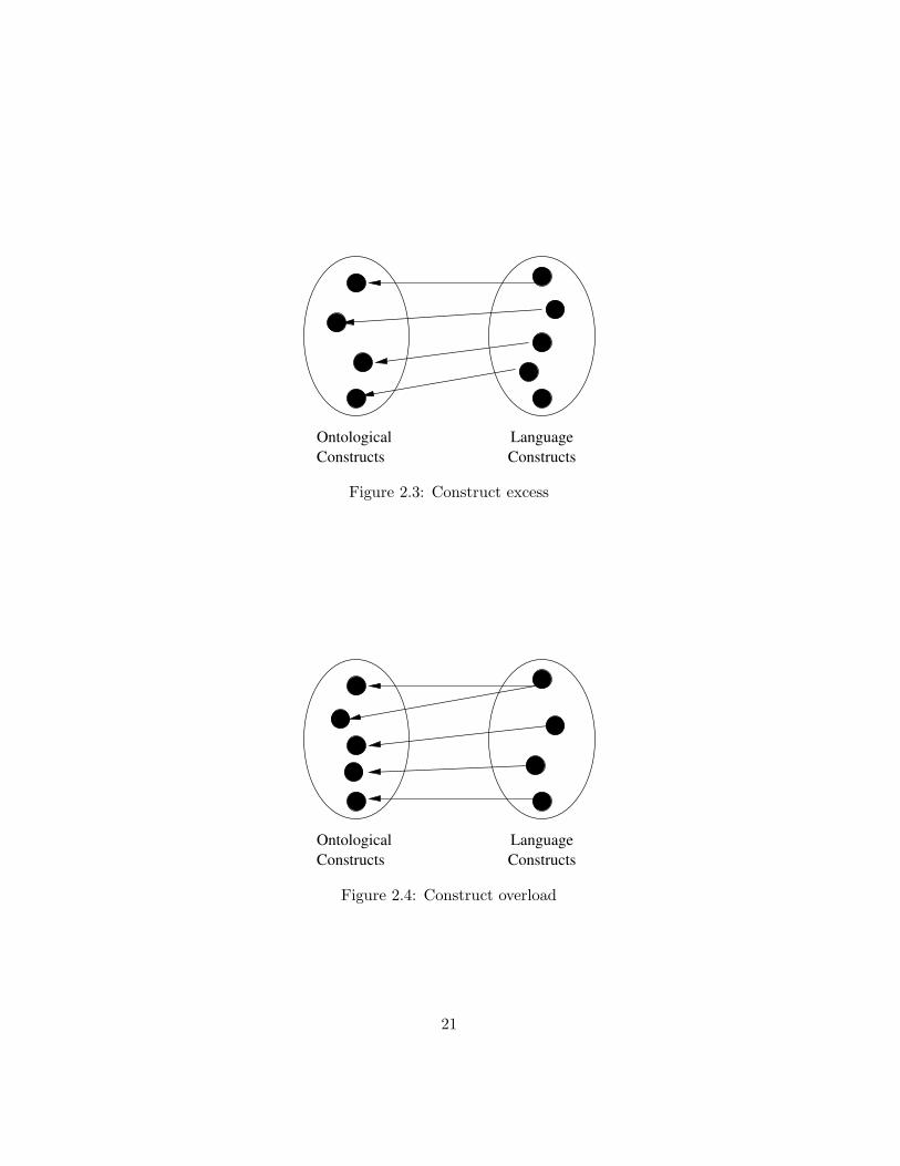
Figure 2.3: Construct excess
OntologicalConstructs
LanguageConstructs
Figure 2.4: Construct overload
21

represent it.
Analysis of the representation mapping can identify construct deficits(Fig. 2.1), situations where the modelling language does not providea construct to represent an ontologically relevant aspect of the realworld. This may lead to incomplete models when the language isused for conceptual modelling. A second potential defect is constructredundancy (Fig. 2.2), where an ontological concept can conceivablybe mapped to two different language constructs. This may lead toconfusion as the modeller has no guidelines on which construct to use.
2. How can a construct of the language be interpreted in terms of thereal-world domain (ontologically)?
To answer this question we propose an interpretation mapping fromthe set of language constructs into the set of ontological concepts whichassigns each language construct an ontological interpretation.
Analysis of this mapping can identify language constructs that haveno ontological interpretation (construct excess, Fig. 2.3) or have mul-tiple ontological interpretations (construct overload, Fig. 2.4). Use ofa construct without ontological interpretation may lead to an ontolog-ically meaningless model. Construct overload can lead to ambiguousmodels as it is unclear which interpretation to chose. This can leadto misunderstandings and misinterpretations during the analysis anddesign process and result in a faulty information system.
Together, these mappings assign real-world, ontological semantics to amodelling language. A mapping provides maximum ontological clarity (aminimal number of defects) if it is bijective (Wand and Weber, 1993), i.e. aone-to-one mapping that maps all elements.
Our analysis will propose representation and interpretation mappingsand analyzes the mapping for defects. Specifically, construct deficits canbe alleviated by suggesting new language constructs. Other defects do notrequire additions to the set of language constructs, but can be solved byproviding appropriate modelling rules, described presently.
2.5 Derivation of Modelling Rules
There are two reasons to introduce modelling rules. First, relationships be-tween ontological concepts should be reflected in the language. Second, the
22

Ontology UMLFigure 2.5: Step 1: Identify ontological concepts and language constructs
23

Ontology UMLFigure 2.6: Step 2: Map ontological concepts to language constructs
24

Ontology UMLFigure 2.7: Step 3: Identify ontological assumptions, relationships and con-straints between concepts
25

Ontology UMLFigure 2.8: Step 4: Transfer ontological relationships by virtue of mappings,thereby deriving modelling rules
26

representation and interpretation mappings should exhibit minimal ontolog-ical defects.
Transfer of Assumptions Once the ontological semantics are assignedand language constructs are mapped to ontological concepts, the mappingscan be used to transfer ontological assumptions to the language. An ontologymay suggest that certain situations are possible in the real world whileothers are not. By virtue of the mappings, some combinations of languageelements may therefore describe possible real world situations while othersmay describe impossible ones. Thus, if there are rules or constraints thatrelate ontological concepts, then by virtue of the mapping, these same rulesor constraints must also hold between the mapped language constructs, inorder to allow only models of possible real-world situations. Hence, theontological mapping can lead to modelling rules on how to use the languagefor conceptual modelling.
Figures 2.5 through 2.8 show this process. First, the relevant ontologicalconcepts and language constructs are identified (Fig. 2.5). In a second step,both representation and interpretation mappings are proposed (Fig. 2.6,Sec. 2.4). Third, relationships between ontological concepts are analysed(Fig. 2.7). Fourth and last, these relationships are then transferred to thoselanguage constructs that are mapped to the ontological concepts (Fig. 2.8),thereby generating modelling rules. These rules constrain the use of thelanguage in such a way as to allow only the modelling of possible real-worldsituations.
For languages with a well-formalized syntax such as UML, the properusage of language elements can be enforced by proposing constraints on themeta-model elements. The constraints restrict the set of possible models toallow only the modelling of possible real world situations. These meta-modelconstraints formalize real-world modelling rules in the syntax of a language;they govern the way in which language constructs may be combined to formontologically valid models.
Ensuring Ontological Clarity A mapping provides maximum ontolog-ical clarity if it is bijective, i.e. a one-to-one mapping that maps all el-ements. Mappings which are not bijective exhibit undesirable ontologicaldefects (Wand and Weber, 1993).
To achieve a bijective mapping, it may be necessary to map language
27

constructs to ontological concepts only if they appear in a particular con-text: Suppose that a language provides a construct which, depending onthe context in which it is used, expresses two different real-world situations.Ontological clarity can be achieved by proposing appropriate modelling ruleswhich map that construct, when used in the first context to the one ontolog-ical concept and map it, when in the second context, to the other ontologicalconcept. Such rules can be enforced by placing constraints on the meta-model.
There are two important things to note about this method. First, whilethe derived rules may be appropriate for conceptual modelling, they mightnot be obvious or applicable when the language is used for IS design purposesonly. It is not the purpose of this work to show modelling rules for ISdesign. Instead, we intend to extend the use of design languages into real-world organizational and business modelling. Second, such rules do notnecessarily guide us in how to perceive the world. Thus, we might suggestrules on how to model objects and classes, but not on how to identify them.
2.6 Use of Meta-Models
A meta-model is a description of the language elements and the languagesyntax in the same or another language. The UML meta-model is specifiedin UML itself, with the help of the object constraint language OCL, which isofficially a part of UML. OCL is used in the specification of UML to restrictthe possible combinations of model elements. The UML specification OMG(2001) makes extensive use of this mechanism. As the UML meta-modelitself is a UML model, this research also makes use of OCL to formallydescribe constraints on UML model elements.
The lack of a meta-model and a widely known language for the BWW-ontology has been partially addressed by Rosemann and Green (2000, 2002)who propose a model based on entity relationship (ER) diagrams. This metamodel could serve as the basis for comparing modelling languages or method-ologies (Davies et al., 2003; Rosemann and Green, 2002; Rosemann and zurMuhlen, 1998). However, their model omits central elements of the BWWontology such as states and state transitions. Also, the UML meta-model isformalized in UML itself, not ER diagrams. These two reasons prohibit theuse of a formal meta-model based approach, e.g. schema matching (Batiniand Lenzerini, 1986; Rahm and Bernstein, 2001), for the time being. This
28

last point is also recognized as a hindrance by Davies et al. (2003) who en-courage the use of meta-models for comparing ontologies and languages andsuggest that such kinds of analyses can benefit from meta-models by beingforced to be comprehensive.
Any proposed changes to the meta-model stem from three sources:
• Construct deficits:
Problems of missing constructs to express ontological concepts can besolved by introducing new language elements. These new elements areadditions to the meta-model.
• Lack of ontological clarity:
When a naive mapping, a mapping that does not consider relation-ships among language constructs or among ontological concepts, leadsto ontological defects such a construct overload, modelling rules canbe proposed to limit the mapping to certain contexts in which the lan-guage construct is used. These limitations may be expressed by OCLconstraints on UML meta-model elements.
• Transfer of ontological assumptions:
Relationships and constraints that exist between ontological conceptscan be transferred to the language by virtue of an ontologically clearmapping. If a relationship ro exists between two ontological conceptsO1 and O2 which are mapped to language constructs L1 and L2 re-spectively, we can propose a relationship rl in the language betweenconstructs L1 and L2.
Such relationships are constraints on possible real-world situations.Language elements should be usable in only such a way as to allowmodels of possible real-world situations and deny modelling impossiblereal-world situations. In simple cases such relationships or constraintsmay be expressed by adding a relationship or modifying an existingrelationship. More complex cases may additionally involve OCL con-straints.
The three sources of changes can lead to two types of changes:
• Additions or changes to the UML meta model elements:
29

Additions or changes to the UML meta-model elements can take anumber of forms, e.g. changes in association multiplicities, additionof associations between formerly unrelated meta-model elements, oradditions of classes of language elements4.
We attempt to restrict changes to the UML meta-model to a mini-mum and instead prefer to employ OCL. Our aim is not to propose ameta-model of the BWW-ontology in UML, nor do we want to pro-pose changes to the UML meta-model which would lead to an exactmatch with the BWW-concepts and assumptions. UML should re-main an object-oriented language whose primary use is for IS design.We aim to find an ontological interpretation which requires the leastreinterpretation and preserves the original language elements and theirvalid combinations as much as possible. We wish to preserve as muchas possible the constructs and syntax necessary to support IS designand all object-oriented principles such as encapsulation, classification,message passing, etc.
As a consequence, we refrain from changing aspects such as the useof composition or aggregation instead of ordinary associations. Anexample of this is the definition of an ”Instance” in the meta-model asa composite of zero or more ”AttributeLinks” (values of attributes).While this is correct for a description of a software design, instancesin the real world are of course described by, not composed of, one ormore attribute values. Hence, this should be modelled by an ordinaryassociation. There exist a multitude of similar cases in the UML meta-model but we refrain from suggesting changes to these. Instead, we relyon the reader of a model to interpret the semantics of these associationswith respect to the real world.
• Specification of constraints in OCL:
Often the ontological assumptions can be expressed using the elementsof the existing meta-model or the suggested alterations to the meta-model. In these cases changes to the meta-model elements are notrequired and instead we rely on OCL to specify our proposed rulesformally.
4All additions to the meta-model and OCL expressions are based on version 1.4 of theUML meta-model OMG (2001). A full discussion of the meta-model is beyond the scopeof this paper, the reader is assumed to be familiar with the model. Hence, additions tothe meta-model are often suggested without depicting the larger context in which theseare embedded.
30

The changes to the UML meta-model are syntactic in nature and bythemselves do not affect the semantics of UML vis-a-vis the real world.These semantics are determined by the ontological mappings that we assign,not by the meta-model.
2.7 Scope of Mappings
Chapter 1 outlined our motivation for incorporating ontological semanticsinto language meta-models. Besides facilitating CASE tool support, meta-model level work allows inter-diagram considerations and modelling rules.UML as a graphical language comprises nine distinct diagrams: use casediagram, class and object diagrams, sequence and collaboration diagrams,statechart and activity diagrams, component and deployment diagrams. Notall of these are necessary for every purpose. In fact, the last two in this listare considered implementation diagrams, concerned with the physical pack-aging and distribution of software to hardware components. However, theUML meta-model provides the underlying integration of these diagrams byproviding relationships between language constructs used in different dia-grams. Thus, a meta-model analysis allows a comprehensive and integratedanalysis of all UML diagrams.
Such a comprehensive approach is important. Any assignment of se-mantics to language constructs should not be done individually for eachconstruct. Instead, it must be done before the background of the whole lan-guage as an interconnected set of constructs, not as a set of independent sym-bols. Furthermore, the interpretation and representation mappings shouldattempt to preserve the relationships among language constructs, whetherthey are formal syntactic constraints or only exhibited in common usage.
As an example, consider the UML-construct ”object”. UML suggeststhat each object may have a UML-construct ”state” associated with it. Anymapping of ”object” and ”state” should attempt to preserve this relationshipbetween the concepts to which ”object” and ”state” are mapped in theontology. If necessary, different mapping must be suggested for ”objects”and ”states” in different contexts.
The alternative, individual mapping of constructs and disregarding anyrelationships between them, may lead to simpler representation and inter-pretation mappings. However, these may turn out to contradict ontologicalassumptions. For example, mapping action states to ontological states will
31

contradict the ontological assumptions that state transitions occur withina single entity. When that is the case, either the ontological assumptionsmust be dropped, or the existing language meta-model must be discarded.To do the first is impossible, as the ontology is externally given, while thesecond suggestion may significantly alter the language.
Despite this argument for a comprehensive approach, this thesis does notconsider the language constructs used in the two implementation diagrams,component and deployment diagrams, nor those in use case diagrams. Thesethree diagrams explicitly contain the information system or parts thereof asmodel elements. As this thesis is concerned with conceptual modelling of thebusiness and organization, not the software, these diagrams are not relevantto the purpose of this thesis.
Furthermore, these three diagrams model the information system in thecontext of entities such as organizational actors, hardware, etc. which areexternal to the IS, e.g. actors interacting with a use case, packages beingdistributed to hardware nodes. As the IS is a representation of the real word,these IS-external entities must consequently be representations of thingsexternal to the real world. This is clearly not possible. Hence for the purposeof assigning business semantics to UML for conceptual modelling, thesediagrams are not relevant. The IS-external entities in these diagrams cannotbe mapped to any ontological concept, as there exists no such concept thatis external to the real world. Consequently, for the purpose of conceptualmodelling, they are ontologically excessive.
32

Chapter 3
Prior Research
Research focussing on the analysis of domains for IS design has a long tradi-tion in software engineering under the name of domain analysis. Similarly,research to formalize UML is not new and ontologies have been used for theanalysis of IS modelling languages before. These three streams of researchhave had little contact with one another and different aims and goals. Thischapter examines the relevant work and points out weaknesses and differ-ences to the current work.
3.1 Domain Analysis
In the area of software engineering or software design, it has been recognizedthat, for effective reuse of software artifacts, an understanding of the appli-cation domain is necessary. Within that research area, the term domainanalysis has come to signify the attempt to understand the area of appli-cation of a software system. Domain analysis attempts to abstract fromthe specifics of a particular IS and attempts to model the features of theapplication domain in order to build artifacts that enable reuse.
Most of this research views domain analysis not necessarily as the anal-ysis of the real-world but rather as the first step in the development of areusable and expandable software architecture or framework (Arango, 1989;Morandin et al., 1998; Philippow and Riebisch, 2001; Jayase et al., 2001).Thus, a domain model is not necessarily a faithful representation of the realworld. Domain analysis then is the identification and documentation of com-
33

monalities and differences that can occur across different implementationsof a domain framework or domain architecture.
Object-oriented techniques have been proposed for domain analysis asthose techniques became increasingly popular with software engineering (Go-maa, 1992). The focus of this early use of object-oriented techniques hasbeen the identification of variability in a domain, following the promise ofmore flexible software design by OO proponents. Therefore, domain anal-ysis using object-oriented techniques is able to explicitly support reuse ofsoftware components (Cohen and Northrop, 1998) and the domain modelsinclude representation not only of the physical world, but also elements ofdata abstraction, control and algorithms (Gomaa, 1992).
This focus on software reuse is also evident in (Galfione et al., 2000):”[domain analysis is] a methodology to support the identification, collectionand organization or the artefacts used in software development”. Only toa secondary degree is domain modelling concerned with real-world models.Instead, it should specifically take into account IS considerations such asreuse and software configuration issues (Cohen and Northrop, 1998).
The general process of object-oriented domain analysis begins with do-main exploration and modelling followed by specification of systems andarchitectures which include ’hot spots’, points of variability that must beconfigured to yield concrete models (Morandin et al., 1998). With the in-creasing calls for object-oriented techniques for domain analysis (Cohen andNorthrop, 1998; Gomaa, 1992), the use of UML has also been suggested.However, UML cannot express variability required for domain models toadapt to various similar domains and needs to be expanded to include con-structs for instantiating concrete models (Morisio et al., 2000; Philippow andRiebisch, 2001). In this sense, domain analysis is closely related to referencemodels, which have also been examined ontologically. However, a differentmethodology than the one proposed here must be used for this (Fettke andLoos, 2003).
Domain analysis embraces object-oriented techniques for the purposeof constructing models for software reuse. This contrasts with our under-standing of conceptual modelling which specifically excludes any softwareconsiderations. Consequently, proposals to extend UML for domain anal-ysis focus on expressing variability, not on real-world semantics. Domainanalysis does not distinguish between the real world and the real world asviewed for the purposes of IS design. Moreover, real-world semantics forUML are implicitly assumed and taken for granted. In contrast, this re-
34

search does not accept the suitability of object-oriented languages a-priori.Instead the primary objective of this research is to assign semantics to en-sure this suitability. In this way, the results of this research can further thegoals of domain analysis.
3.2 UML Semantics
Another related stream of research is the formalization of UML. This re-search has taken UML from a purely graphical language with few rules toa language based on a rigorous meta-model that governs the applicationof language constructs. An important result of the precise UML (pUML)1
group and the drive for formalization has been the UML meta-model (Evansand Kent, 1999; Evans et al., 1999a) which has been described in UML itselfwith the help of the object constraint language OCL. This meta-model hasbeen adopted into the language standard (OMG, 2001) and is used as oneof the foundations of this work.
This section briefly describes recent efforts at assigning not only formalsyntax but also formal semantics to UML.
Breu et al. (1997, 1998b) motivate the formalization effort by arguingthat a formal semantics provides advantages for modellers and tool develop-ers. They recognize that UML models consist of different diagrams express-ing various views or perspectives which must be integrated. Hence, UMLconstructs are mapped to various mathematical and logical models such asSYSLAB and Z (Breu et al., 1998a; Bruel and France, 1999).
The pUML group works towards a semantics for UML by formalization inlogic. This kind of semantics is concerned either with internal consistency(and is thus a coherentist view of semantics) or defines semantics of anIS as the input/output relationship or transformation rules (and is thus aprocedural semantics). Evans et al. (1999b) propose a formalization of UMLby specifying it in the formal language Z, arguing that Z better supportslogical inferences and proof than the OCL language which is part of UML.Evans (1998); Evans and Clark (1998) show how UML class diagrams canbe formalized in Z. Lano and Evans (1999) relate UML diagram elements toa first order set theoretic model called RAL (Real-time Action Logic) anddemonstrate how this can lead to transformation rules that can take UMLmodels from analysis to design.
1http://www.cs.york.ac.uk/puml
35

Various other works claim to assign formal semantics to UML. Lanoand Bicarregui (1999) use formalization as a tool to derive transformationrules for UML models, Lilius and Paltor (1999) provide a formalizationof UML state machines and Overgaard (1999); Overgaard and Palmkvist(1999); Knapp (1999) suggest a formal treatment of interaction, especiallycollaborations and use cases.
However, all of this research relates to internal consistency and the for-malization of UML in logic and mathematics, not to its relationship to thereal world. Specifically, these kinds of semantics are not correspondence se-mantics, i.e. the meaning of constructs is not determined by their relationsto extra-linguistic elements, such as real-world elements. By not relating thelanguage to extra-linguistic entities they fail to impart real-world meaning toUML constructs. Thus, none of these approaches make clear the meaning ofUML constructs in the business or organizational domain. They answer thequestion of what a particular UML construct means e.g. in the Z language,but this simply moves the problem to the real-world semantics of Z.
3.3 Ontological Analysis
This section describes research on how ontology and specific ontologies havebeen used for the analysis of IS modelling languages. While the researchdiscussed in the last section lacked this element, most of the work discussedin this section lacks the formal aspect that is common to research discussedin that section.
The use of ontology in IS research dates back to the work by Wand (1989)who introduces the main concepts of Bunge’s ontology to the IS field andexamines five principles of object-oriented concepts. He goes on to suggestontological semantics for very general object-oriented concepts without ex-amining a specific language. Early work (Wand and Weber, 1989) identifiesimplementation related languages and constructs that are distinct from rep-resentation related constructs. Only the latter are deemed suitable for rep-resenting real-world domains, while the former relate to software artifacts.Among such implementation related constructs are messages and messagepassing concepts (Parsons and Wand, 1991, 1997). This finding reflects theheritage of the object-oriented approach from software engineering (Opdahland Henderson-Sellers, 2001).
Only later is the notion of ontological evaluation developed and applied
36

to data flow diagrams (Wand and Weber, 1993). Next to classification theory(e.g. Lakoff, 1987) and speech act theory (Austin, 1962; Searle, 1969; Aura-maki et al., 1988, e.g.), ontology is proposed as a third basis for evaluatingmodels and modelling languages.
Parsons and Wand (1997) describe the applications of ontology in gen-eral, and the BWW ontology in particular, to the evaluation of systemsmodelling techniques and use it to the clarification of the notion of object insystems analysis. Specific focus on object-oriented techniques has led to aproposed modelling process (Wand and Woo, 1999) for object-oriented lan-guages that extends from real-world conceptual modelling to high level ISdesign (Wand et al., 2000). The modelling rules and process are generic andnot specific to a particular language. Wand and Woo (1999) do not providedetailed syntactic rules. As such, the present research is complementary totheir process.
Recent work has focussed on specific languages and even specific lan-guage constructs such as the relationship construct in entity relationship(ER) diagrams (Wand et al., 1999). As object-oriented techniques gainedpopularity in IS design, various studies have examined the OPEN ModellingLanguage (OML). OML is an experimental variant of UML and, when ana-lyzed using the BWW ontology, exhibits a number of overloaded, excessiveor redundant language constructs as well as construct deficits (Opdahl andHenderson-Sellers, 1999; Opdahl et al., 1999; Opdahl and Henderson-Sellers,2001). However, no modelling rules have been proposed.
Ontological analysis has also been successfully applied to more tradi-tional, non object-oriented languages. The ARIS language (Scheer, 1999) isa combination of four distinct and slightly overlapping languages. Ontologi-cal analysis indicates that even as a combination of languages, ARIS exhibitsontological constructs deficit and cannot express the BWW-ontology com-pletely (Green and Rosemann, 2000).
On a more critical note, Rosemann and Green (1999) suggest that on-tological analyses neglect the purpose of the model and characteristics ofthe user or modeller. Thus, they argue, the deficiencies identified throughontological analysis may not be relevant to practical modelling situations.They demonstrate this using examples of activity based costing and workflowmodelling and suggest that the ontologies used should be either amendedor restricted to fit the purpose and user. However, as argued above, anontology is a most fundamental philosophical position and as such is nottied to a specific purpose. It should be departed from only if the results of
37

research based on that position obviously violate accepted truth. Moreover,some languages are not intended to completely express the BWW ontol-ogy (Opdahl and Henderson-Sellers, 2002; Parsons and Wand, 1991, 1997),and changes to the BWW-ontology to accomodate e.g. software specificconstructs should not be considered.
Analysis of UML Two other research groups have used the BWW-ontology to analyze the UML language (Opdahl and Henderson-Sellers,2002; Dussart et al., 2002), the former being more comprehensive than thelatter. Both works stop short of suggesting modelling rules to be incorpo-rated into the meta-model, but instead analyze the language for ontologicaldeficiencies. This chapter reviews the different choices those authors madein mapping ontological concepts to UML language elements. Since a fulldiscussion of the research is beyond the scope of this thesis, the mappings ofthe most fundamental constructs and concepts will be discussed. The endof this section draws some general conclusions from this discussion.
Both (Opdahl and Henderson-Sellers, 2002) and (Dussart et al., 2002)map UML-objects to BWW-things, but in order for UML-objects not tobe overloaded, this interpretation mapping needs to be restricted to thoseobjects which are substantial. Other UML-objects must be mapped to e.g.BWW-properties, and the modeller must be given a rule for this mapping.The representation mapping from BWW-things into objects is not problem-atic. Dussart et al. (2002) map a BWW-thing also to a swimlane, or moreformally, a partition in UML. However, this leads to state transitions be-tween two objects, which, when mapped back to BWW-things, should notbe possible.
Opdahl and Henderson-Sellers (2002) as well as Dussart et al. (2002)map BWW-classes to UML-classes. However, this neglects the fact that aUML class is a specification, not a collection of things like a BWW-class.Collections of things are modelled as aggregates and composites in UML.
BWW-properties are mapped to UML attributes (intrinsic properties)and associations (mutual properties) by Opdahl and Henderson-Sellers (2002)while (Dussart et al., 2002) make the unorthodox mapping of BWW-propertiesto UML-activities and UML-partitions. The first mapping has to con-tend with the fact that properties are mapped to two very different UML-elements, while the second mapping brings with it the problem that parti-tions are not features of UML-objects, so that the BWW-properties mappedto them are not actually features of UML-objects. This mapping also over-
38

loads the partition construct to represent both things and properties.
Both Opdahl and Henderson-Sellers (2002) and Dussart et al. (2002)map BWW-states to UML-states and both attempt to find a mapping forthe BWW-state history of a thing, the collection of states through time ofa thing. Dussart et al. (2002) map the history to the UML-shallow historyconstruct, which does not fully capture the meaning of the BWW-historyconcept. Opdahl and Henderson-Sellers (2002) on the other hand map theBWW-history to a UML-object lifeline, which, while often shown in sequencediagrams, is not a formal UML element defined in the meta-model. Whilethis captures some sense of a thing’s history, it does not, or only indirectlyby tracing messages to state transitions, reflect the series of states that athing has gone through.
Interestingly, Dussart et al. (2002) map the conceivable state space of athing to a UML-state machine and the lawful state space to the set of sub-states, recognizing that a state machine contains states just like a state spacecontains states. Opdahl and Henderson-Sellers (2002) find no counterpartin UML corresponding to the conceivable or lawful state spaces. The map-ping to UML-state machines however requires that these are state machineswhich are associated with a classifier, i.e. those which specify the behaviourof instances or objects, not those which specify the behaviour of methods.This must be ensured by an appropriate modelling rule. While this is a steptowards capturing the meaning of the conceivable state space, one wouldalso need to include states and sub-states of all state machines which de-fine behavioural features of UML-objects. With this extended reading, themapping by Dussart et al. (2002) is a good interpretation mapping.
Opdahl and Henderson-Sellers (2002) map ontological stable states toUML-final states and vice versa. This neglects the fact that BWW-stablestates are defined through interaction, a concept which should be mapped toUML-events or actions. Hence intermediate states may also be consideredstable, if state transitions from such states are caused by external interac-tion.
Opdahl and Henderson-Sellers (2002) propose an interpretation mappingwhich maps most interaction related constructs such as transitions, guardconditions, actions, etc. to BWW-laws. On the other hand, a BWW-law isnot mapped to the obvious equivalent of a UML-constraint. This mappingis problematic without clear guidelines to the modeller as it shows a lot ofambiguity with respect to the representation of BWW-laws in UML.
39

There are a number of important things to note. First, in Dussart et al.(2002) it is unclear whether the mappings given are interpretation or rep-resentation mapping or both. Also, their research is restricted to UML ele-ments used mainly in activity charts and concerned with interaction. BothOpdahl and Henderson-Sellers (2002) and Dussart et al. (2002) suggest map-pings that clearly show ontological deficiencies such as overloaded languageconstructs or construct redundancy. This is the result of trying to map theelements without restricting the applicability of the mappings to make themappings less problematic. Their conclusions, that the languages are defi-cient, is a direct result of this. On the other hand, our research attemptsto find rules by not only transferring ontological assumptions to the UML-language but also, and perhaps more importantly, suggesting ways in whichto enhance the ontological clarity of the mapping and reduce the ontolog-ical deficiencies. For example, we restrict the mapping of UML-objects toBWW-things to substantial objects only, thus reducing ontological deficien-cies and providing a clear modelling rule.
Second, there exist elements in the UML-meta-model which have no se-mantic role to play. These are not mapped to BWW-elements in the presentresearch and no modelling rules need to be derived. Other UML-constructssuch as sync states, focus of control, timing mark, etc. that are mappedby Opdahl and Henderson-Sellers (2002) are not mapped in this thesis dueto the following reasons. First, we believe that these are very UML spe-cific constructs that have no general object-oriented counterpart or mean-ing. Second, these constructs are specifically related to IS implementation.Third, these constructs, if they were mapped, would result in ontological de-ficiencies in the mapping, such as construct overload. In contrast to Opdahland Henderson-Sellers (2002) we have therefore decided not to map suchUML-constructs.
To summarize, previous work has concentrated on ontological evaluationof languages. In contrast, our present aim is to employ ontology in a moreprescriptive way and assign ontological semantics to a language. The presentwork builds on earlier work (Evermann and Wand, 2001a,b) to use the BWWontology not only as the basis to determine ontological deficiencies, but alsoin a constructive way: Through the interpretation or representation map-ping we can assign real-world meaning (ontological semantics) to languageelements. Hence, this tells us not only whether to use such languages tomodel the real world, but also how to use them. This work also builds onthe formal syntax and formal semantics of the UML meta-model and theobject constraint language, attempting to bridge the two diverse streams
40

of research. It is the first study to employ formal descriptions of the rulesresulting from an ontological analysis.
41

Chapter 4
Static Structure
Our world consists of a static structure of things with their properties,changes in things and interactions of things. Hence, this is the order ofthe following discussion. Each of the following chapters first employs a rep-resentation mapping, followed by an interpretation mapping. From thesemappings a number of modelling rules follow as consequences. These arefirst stated informally and then formalized using the UML meta-model andOCL. As stated in Sec. 2.5, the derived modelling rules are intended forconceptual modelling of real-world domains. They are not applicable foruse of UML in software design and software modelling.
4.1 Representation Mapping
The representation mapping is intended to find a first UML representationof the basic ontological notions. The basic building blocks of the worldare things, which possess intrinsic and mutual properties. Things can beclassified into classes or natural kinds. This section attempts to map theseontological concepts to UML constructs. By doing this we narrow the possi-ble uses of UML constructs. This is reflected in the derived rules. We beginour discussion with the most basic concept, that of a thing.
42

4.1.1 Things
A primary concern of every modelling endeavour is the identification of thebasic structure of the domain. In UML, the modeller needs to decide whatto model as an object and what not to model as an object. Questions suchas ”is an employee an object?” or ”are skills or transactions objects?” areof fundamental importance.
Because every BWW-thing is an entity in the world, we propose that aBWW-thing is equivalent to a UML-object. The inverse is not necessarilytrue: Not every UML-object is equivalent to a BWW-thing. Entities such as”location”, ”jobs”, ”orders” 1 are not things in the ontological sense but arestill often modelled by UML-objects. If we want to assign the ontologicalsemantics of a thing to a UML-object, we must follow rule 1:
Rule 1 Only substantial entities in the world are modelled as objects.
Fig. 4.1 is an example UML class diagram to show the implications ofour rule. The model is taken from (Fowler and Kendall, 2000) and describedas an anlysis level model, not a design model. It depicts a situation typ-ically found in object-oriented models. Note that according to rule 1 theUML objects ”Order” and ”OrderLine” should not be modelled here as theyhave no substantial counterpart in the real-world. Hence, we must find analternative description for entities such as ”Job”, ”Order”, etc.
4.1.2 Properties
Having identified what to model as an object, and what not to, we findthat many of the items that we rejected as objects are properties of things.For while an employee should be modelled as an object, skills of employeesshould not, nor should addresses of employees as these are not substantialthings. Instead, they are BWW-properties of things and we suggest theyshould be modelled as UML-attributes.
In ontology, every thing possesses properties, which may be either in-trinsic, possessed by the thing alone, or mutual, joint properties of two ormore different things. We propose that all properties find their equivalent
1We are not interested in the physical manifestations, such as an order form. Theseare merely descriptions of an order.
43

Order
dateReceivedisPrepaidnumber:Stringprice:Money
dispatch()close()
Customer
nameaddress
creditRating():string
CorporateCustomer
contactNamecreditRatingcreditLimit
remind()billForMonth(Integer)
PersonalCustomer
creditCard#
Employee
Order Line
quantity:Integerprice:MoneyisSatisfied:Boolean
0..1
*
sales rep
*
1
lineitems
Product* 1
* 1
Figure 4.1: Example UML class diagram without ontological semantics(Fowler and Kendall, 2000)
44

in UML-attributes. The following paragraphs examine intrinsic and mutualproperties.
Intrinsic Properties
We propose that BWW-properties of things are equivalent to UML-attributesof an object. Thus, when using UML for conceptual modelling, we suggestfollowing rule 2:
Rule 2 Ontological properties of things must be modeled as UML-attributes.
One implication of this rule is a clear distinction between attributesand objects which reflects the clear distinction between BWW-propertiesand substantial things (see also Wand et al., 1999). For example, whilean address is a property of a person, it is not part of a person. The entity”Person” in the information system is a representation of a real person and assuch can be compositionally associated in the IS with another representation,”Address”. In the real world, a person is the physical entity but an addressis a conceptual construct and they cannot be compositionally associated.Rules 1 and 2 together lead us to propose the following:
Corollary 1 Attributes in a UML-description of the real world cannot referto substantial entities.
Consider for example a person that has a language skill. Because a skillis a conceptual entity, i.e. it is not substantial, it cannot be modeled as anobject but must be an attribute of the person 2. Ontologically, a skill is aproperty of a person.
The above rules relate model elements to elements of the real world andcan therefore not be formally expressed in the meta-model or in OCL.
Mutual Properties
The results regarding the representation of properties as attributes are notrestricted to intrinsic properties but should be applicable to all properties.
2Note that in IS design, a skill is often modelled as an object or entity, but this mustbe the second step in the IS analysis and design process, after the description of the realworld.
45

Hence, mutual properties must also be represented by UML-attributes. Thissection will discuss mutual properties in detail.
The BWW-ontology distinguishes intrinsic properties from mutual prop-erties. The former are possessed by a thing alone while the latter are prop-erties of two or more things. Since all properties must be represented byattributes (rule 2), we propose that attributes of ’ordinary’ UML-classesrepresent intrinsic properties while attributes of association classes repre-sent mutual properties. Recall that mutual properties are properties thatare shared between two things, e.g. the salary of an employee of a companyor the tuition fee of a student of a university. These properties can only beattributed to two or more things jointly, not to a single thing.
A special case of an attribute in UML is an attribute of an associationclass. At this point we are not concerned with associations themselves anddefer that topic for later discussion (Sec. 4.2.7). It suffices to introduceassociations as some kind of ’connection’ between classes, i.e. an associationrepresents some semantic relationship between the objects of the associatedclasses.
We propose that association classes represent bundles of mutual prop-erties, each association class attribute represents a mutual property. E.g.the property ”Order volume” represents a mutual property between a sup-plier and a customer, the property ”Salary” represents a mutual propertybetween an employer and an employee. Note that we specifically do notmake any interpretation of the association construct itself yet.
Rule 3 Sets of mutual properties must be represented as attributes modelledwith association classes.
With this interpretation of a bundle of mutual properties, an associationclass cannot represent or describe substantial entities because in that caseits attributes would be intrinsic ones of a substantial thing.
Corollary 2 An association class cannot represent substantial entities orcomposites of substantial entities.
In the following we show that this is not a limitation. We examine threedifferent semantics of association classes as they are commonly found inobject-oriented models. Based on the above ontological mapping we suggestrules for how these three cases must be treated to conform to our proposedontological semantics. These rules follow from rule 3 and corollary 2.
46

Computer Robot
Controller
Serial#ManufacturerModel
TurnOnTurnOff
controls
Figure 4.2: A substantial association class in UML
1. The association class is intended to represent a substantial entity.
Figure 4.2 illustrates this case. A computer controls a robot via a con-troller device. This device has attributes and operations. In this case,the intended instances of the UML-association class are substantialentities and can thus be described as regular classes. The associationclass attributes are intrinsic properties of the controller device andshould be modelled as such. This motivates the following rule:
Corollary 3 If an association class of an n-ary association is in-tended to represent substantial things, the association should insteadbe modelled as one with arity (n+1).
Fig. 4.3 shows this transformation using the above example. The con-troller association class is reinterpreted as a participant of the nowternary association. It has intrinsic attributes.
2. The intended interpretation of the association class can be identifiedas a composite or aggregate.
Sometimes an association class represents emergent properties of acomposite. When this is the case, the UML model should reflect thiscomposition by showing an aggregation relationship. Figure 4.4 shows
47

Computer Robot
Controller
Serial#ManufacturerModel
TurnOnTurnOff
controls
Figure 4.3: A reinterpreted substantial association class
Processor Memory
Computation
ComputationPower
Figure 4.4: An association class represents a composite
48

Processor Memory
Computer
ComputationPower
Figure 4.5: Reinterpreting an association class as a composite
an example. A processor and memory are associated to perform com-putations. This association has an attribute of computing power. Thisshould instead be modelled properly as a composite with emergentproperties, as depicted in Fig. 4.5.
Corollary 4 An association class representing a composite must in-stead be modelled as a composite with attributes representing emergentintrinsic properties.
3. The association class is intended to represent a set of mutual proper-ties.
Consider the situation depicted in Fig. 4.6. This third case reflects theontological mapping that we have proposed above. A ”Job” is not asubstantial thing and hence cannot be modelled as a class. However,the attributes of the association class ”Job” are mutual attributes ofthe company and the employee. They could be rewritten as a set ofbinary mutual properties:
{ JobTitle(Company, Worker)
Salary(Company, Worker)
StartDate(Company, Worker) }
Additional laws are required to ensure that these properties occurtogether.
49

Company Employee
Job
JobTitleSalaryStartDate
RaiseSalaryTerminate
employs
Figure 4.6: A conceptual association class in UML
Of the three possible intended meanings of an association class one al-ready conforms to our ontological and the other two should not be modelledas association classes because their attributes represent either intrinsic prop-erties or emergent intrinsic properties of composites.
Consequences and Characteristics of Association Classes Recallthat in UML, an association class possesses all the characteristics of a classas well as that of an association. This means that in UML an associationclass can be generalized, participate in further associations, and define op-erations and methods. The next paragraphs will examine whether thesecharacteristics are still attributable to UML association classes with ourontological interpretation.
Ontologically, all change is tied to things. There can be no change with-out a thing that changes. In light of the fact that association classes donot represent substantial things, we propose that an association class as aset of mutual properties cannot possess methods or operations nor can it beassociated with a state machine specifying any behaviour.
Corollary 5 An association class cannot possess methods or operations.
We can express this in OCL as follows:
50

(4.1)context AssociationClass inv:self.feature
->select(f | f.oclIsTypeOf(BehaviouralFeature))
->size()=0
Corollary 6 An association class cannot be associated with a state ma-chine.
(4.2)context AssocationClass inv:self.behaviour->Size() = 0
Moreover, since an association class attribute represents a mutual prop-erty, every association class must possess at least one attribute. While anempty set of mutual properties is still a set and thus technically satisfiescorollary 3, it is ontologically meaningless. Hence we propose rule 7:
Corollary 7 An association class must possess at least one attribute.
(4.3)context AssociationClass inv:self.feature
->select(f : feature | f.oclIsKindOf(Attribute))
->size() > 0
Furthermore, as properties in ontology cannot themselves possess mutualproperties with other properties or things, an association class in UML mustnot be associated with any other class.
Corollary 8 An association class must not be associated with another class.
51
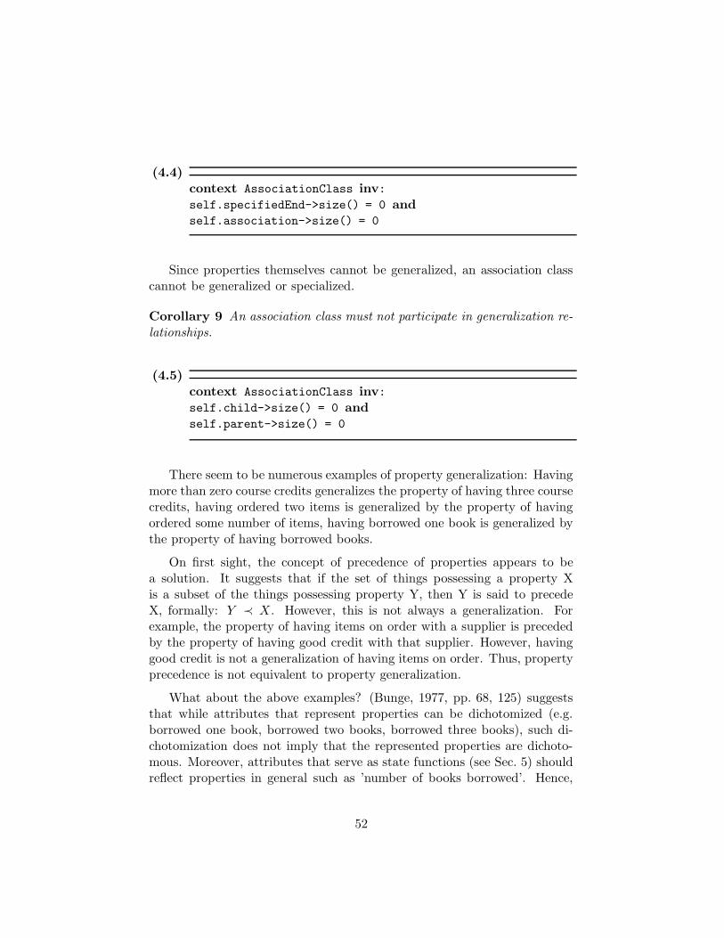
(4.4)context AssociationClass inv:self.specifiedEnd->size() = 0 andself.association->size() = 0
Since properties themselves cannot be generalized, an association classcannot be generalized or specialized.
Corollary 9 An association class must not participate in generalization re-lationships.
(4.5)context AssociationClass inv:self.child->size() = 0 andself.parent->size() = 0
There seem to be numerous examples of property generalization: Havingmore than zero course credits generalizes the property of having three coursecredits, having ordered two items is generalized by the property of havingordered some number of items, having borrowed one book is generalized bythe property of having borrowed books.
On first sight, the concept of precedence of properties appears to bea solution. It suggests that if the set of things possessing a property Xis a subset of the things possessing property Y, then Y is said to precedeX, formally: Y ≺ X. However, this is not always a generalization. Forexample, the property of having items on order with a supplier is precededby the property of having good credit with that supplier. However, havinggood credit is not a generalization of having items on order. Thus, propertyprecedence is not equivalent to property generalization.
What about the above examples? (Bunge, 1977, pp. 68, 125) suggeststhat while attributes that represent properties can be dichotomized (e.g.borrowed one book, borrowed two books, borrowed three books), such di-chotomization does not imply that the represented properties are dichoto-mous. Moreover, attributes that serve as state functions (see Sec. 5) shouldreflect properties in general such as ’number of books borrowed’. Hence,
52

Job
JobTitleSalaryStartDate
Company
RaiseSalaryTerminate
Employee
Terminate
Figure 4.7: Association class and operations in UML
UML-attributes that represent properties should not be dichotomized un-necessarily or artificially.
What about properties such as ’can move’ and ’can fly’? Clearly flyingis a special way of moving. These attributes do not represent propertiesbut potential change in things. Both, moving and flying are activities, notproperties. Thus, they will need to be examined in our section on change(Sec. 5). Abilities should not be modelled as attributes.
In general, precedence of properties in the BWW-ontology is a law. Wewill later see that law statements are represented by UML constraints (seeSec. 6.1.1). Thus, we suggest to use UML-constraints to express generalproperty precedence.
Recall that corollary 5 proscribes that association classes be assignedoperations or methods. How then do mutual properties change?
Given that properties represented in association classes are mutual tothe participants of the association, they may be changed when the thingsrepresented by the participant classes themselves undergo changes. Hence,we propose that methods and operations intended for association classesshould be modelled with the participant classes. In the example of Fig. 4.6,the operation ”RaiseSalary” should be modelled with the company and theoperation ”Terminate” may be modelled with either the company or theemployee or both, depending on the real-world situation. Fig. 4.7 shows
53

this interpretation.
Rule 4 If mutual properties can change quantitatively, methods and oper-ations that change the values of attributes of the association class must bemodelled for one or more of the classes participating in the association, ob-jects of which can effect the change, not for the associations class.
Mutual properties usually occur together. For example, some mutualproperties arise out of interaction, e.g. after a customer and a car rentalcompany interact, there exist a number of mutual properties such as ’Date-Out’, ’DateDue’, ’BalanceDue’, ’DepositPaid’ etc. We suggest that sets ofmutual properties that arise out of one interaction be modelled in a singleassociation class. On the other hand, there exist situations in which unre-lated sets of mutual properties exist. We suggest that each association classexpresses related concurrent properties and that different association classesbe used if sets of properties are not concurrent:
Rule 5 An association class represents a set of mutual properties arisingout of the same interaction.
As a result, different association classes should be used for sets of mutualproperties that arise out of different interaction. Consequently, two classesmay be linked by more than one association. For example, the interactionof a customer ordering an item that gives rise to mutual properties such as’Payment Balance’, ’Expected Delivery Date’, etc. between the customerand the supplier. Consider another interaction when the customer returns adefective product for warranty. Mutual properties such as ’Return Merchan-dise Number’, ’Fault Description’ etc. arise. These two sets of propertiesshould in UML be modelled as two separate association classes between thecompany and the supplier. We suggest further that in cases where the in-teraction is modelled in other parts of the model (see Sec. 6) that the nameof the association class refer to this interaction.
Mutual properties and scope of model It is often the case that mutualproperties are properties of two or more things, some of which are beyondthe scope of the model. In the simple case, a mutual property of two things,one of which is beyond the scope of the model, must then be modelled as anintrinsic property of the other thing. In doing so, the set of other things thatthe property is mutual with becomes part of the co-domain of the intrinsicproperty.
54

As an example, a student that has earned different degrees from dif-ferent universities, e.g. a ’BSc’ from UBC, a ’MSc’ from UofA, a ’MBA’from UToronto and a ’PhD’ from UVic. If the other schools form part ofthe model, an association class should be modelled with an attribute ’De-greeEarned’. However, if the other schools are beyond the scope of themodel, but the degrees earned are not, we must instead model an intrinsicproperty by two attributes, ’DegreeEarned’ and ’School’ (or a single multi-valued attribute).
For the remainder of the discussion, the properties of any thing arerepresented by the union of attributes defined for a class and the attributesof association classes which that class participates in. Expression (B.4)defines this in OCL. As we discuss aggregation in subsection 4.1.3, expression(B.4) in Appendix B already includes as properties all properties of parts ofaggregates.
4.1.3 Composition and Aggregation
Often, the modeller is confronted with the fact that different things arecombined in some way to yield other things. However, not every combinationof things is meaningful. This section will examine composition of things anddevelop guidelines to help ensure ontologically meaningful models.
The composition relationship in the BWW-ontology defines compositethings as being made up of parts. In contrast to UML, it makes no assump-tions as to any ownership or any restrictions on these part/whole relation-ships.
UML distinguishes between composition and aggregation. These differalong two semantic dimensions: In a composition relationship, the parts ofthe composite are existentially dependent on the composite and also cannotbe part of any other composite. In an aggregation, the parts can exist inde-pendently of the aggregate and can also, at the same time, be parts of multi-ple aggregates. The aggregation semantics are equivalent to the ontologicalnotion of composition, whereas the more restrictive UML-composition hasno ontological counterpart.
Rule 6 A composition relation must not be modelled.
This can be expressed in OCL by proscribing the value ”composite” asattribute of an AssociationEnd:
55

(4.6)context AssociationEnd inv:self.aggregation <> "composite"
In some cases it may the case that individuals change behaviour or loseor acquire properties if they become part of an aggregate. These changesmay occur when they become part of the aggregate. Examples of this are thebehaviour of team members as part of teams, employees as part of companiesetc. Once could reasonably argue that team members ’disappear’ once theyleave the team. However, on closer examination, the team members do notdisappear or get destroyed: Changes in properties or behaviour lead to sub-classification, a topic that will be examined closer in Sec. 4.2.3 in connectionwith multiplicities of associations.
Our ontology distinguishes between hereditary and emergent propertiesof composites. The former are properties of some part that the compositealso exhibits, while the latter are properties of the composite that none ofthe parts exhibit. Emergent properties are defined over properties of partsand are thus a function of the properties of the parts. Take for example acomposite of two parts, A and B, each with one property, e.g. u1 and u2.We can define the emergent property k as a function of the properties of theparts:
u1 = 0 u1 = 1
u2 = 0 k = 0 k = 2
u2 = 1 k = 1
The property k is a function of the properties of the components A andB of the composite and can be reduced to these, but it is not exhibited byeither component alone.
In the BWW-ontology, a composite must possess at least one emergentproperty, otherwise there exists not a composite but only a set of things(parts). In other words, a composite things must be more than simply the’sum’ of its parts. This leads us to propose rule 7 as a specific version ofrule 8 below for composites:
Rule 7 Every UML-aggregate must possess at least one attribute which isnot an attribute of its parts or participate in an association with associationclass.
56

Note that under attributes we understand attributes that represent bothintrinsic and mutual properties, as defined in expression (B.4). Hence, wecan formally express the above rule by the following OCL expressions, mak-ing use of expression (B.3) in Appendix B:
(4.7)context Class inv:self.association->exists(a | a.aggregation="aggregate")
impliesself.allNonPartProperties->IsEmpty() = false
Consider again the example depicted in Fig. 4.4 of the processor and thememory. Only the fact that together the processor and memory give rise toa property makes the composition meaningful. Otherwise, the processor andthe memory would simply be two things that happened to be close together.Our rules ensure that only meaningful compositions of things are modelledas an aggregate in UML.
4.2 Interpretation Mapping
The previous section examined the basic ontological concepts of the staticstructure of the real world: Things, properties and composition of things.This section will examine UML and object-oriented concepts and constructs.With the previously made representation mapping in mind we identify theirontological interpretation and explore the consequences of the representationmapping.
4.2.1 Class
In UML, a class is defined as a description of a set of objects which sharethe same attributes and operations. The role of classes in UML as primaryconstruct is that of templates or ’object factories’. Objects depend on classesand cannot exist without them. Objects are created from class templates,i.e. an object as a class instance possesses all methods and attributes definedfor its class. A UML-class is a description of a number of objects.
A BWW-natural kind is the set of things that adhere to the same set of
57

laws and in turn exhibit the same type of behaviour. A natural kind is a setof things, not a description or a template of or for a set of things. Sets differsemantically from classes in that they are defined over pre-existing thingsand do not exist without the things that comprise them.
Thus, UML-classes and BWW-natural kinds are fundamentally different,hence we refrain from mapping them onto each other. However, the BWW-ontology provides the concept of a functional schema. Such a schema is adescription of the properties of a thing or a set of things with like properties.We propose that a UML-class is equivalent to a functional schema describingthe entities that form the corresponding BWW-natural kind.
Because all things possess properties and adhere to some laws, the func-tional schema must reflect this and so we suggest the following rule:
Rule 8 All UML-classes must possess at least one attribute or participatein an association.
It is however possible that things possess attributes inherited from theirparts. They are then defined as aggregate classes which participate in ag-gregations. In that case, rule 7 is applicable, which in turns yields rule8.
The following OCL expression is an invariant on the Class construct whichformalizes this rule:
(4.8)context Class inv:self.allProperties->IsEmpty() = false
Another important aspect of classes in object-oriented approaches is thatof an ’object factory’, i.e. classes serve to ’instantiate’ or create objectsaccording to the class template. Since in the BWW-ontology things cannotbe created or destroyed, this aspect of a class has no ontological equivalent(but see Sec. 4.2.4).
4.2.2 Object Identity
Object identity, while not explicitly modelled in UML, is an important as-pect in object-oriented techniques. In our ontology, things are identified
58
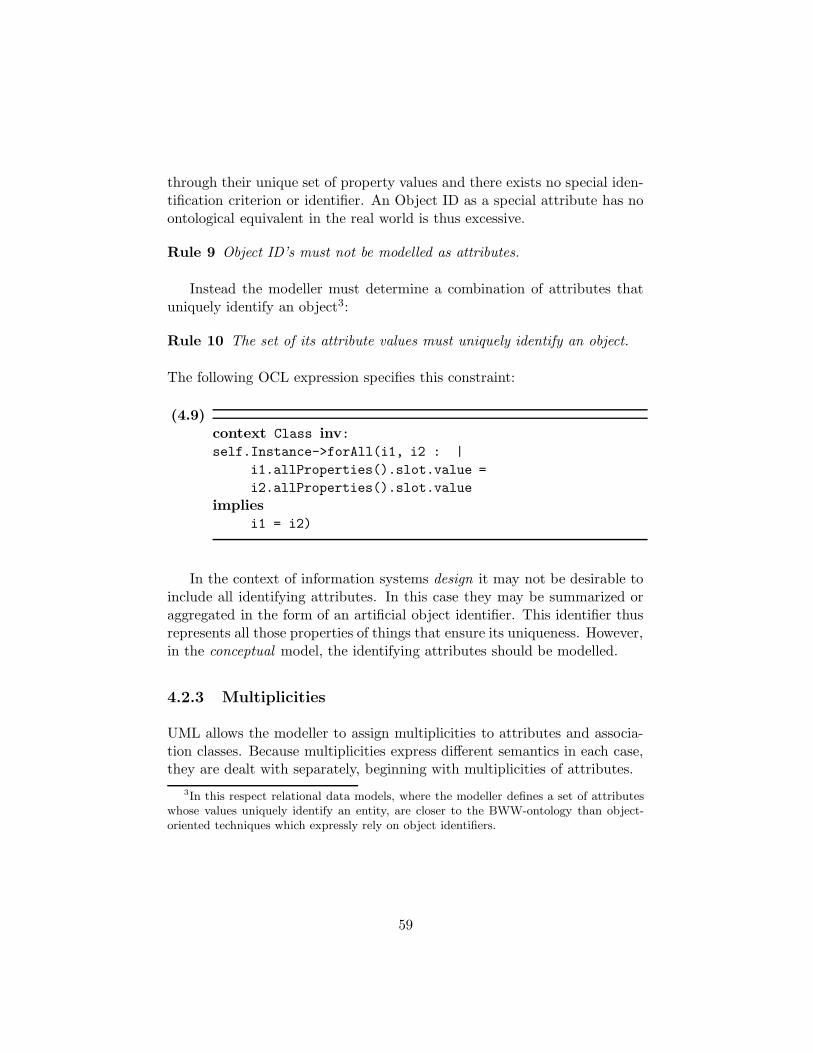
through their unique set of property values and there exists no special iden-tification criterion or identifier. An Object ID as a special attribute has noontological equivalent in the real world is thus excessive.
Rule 9 Object ID’s must not be modelled as attributes.
Instead the modeller must determine a combination of attributes thatuniquely identify an object3:
Rule 10 The set of its attribute values must uniquely identify an object.
The following OCL expression specifies this constraint:
(4.9)context Class inv:self.Instance->forAll(i1, i2 : |
i1.allProperties().slot.value =
i2.allProperties().slot.value
impliesi1 = i2)
In the context of information systems design it may not be desirable toinclude all identifying attributes. In this case they may be summarized oraggregated in the form of an artificial object identifier. This identifier thusrepresents all those properties of things that ensure its uniqueness. However,in the conceptual model, the identifying attributes should be modelled.
4.2.3 Multiplicities
UML allows the modeller to assign multiplicities to attributes and associa-tion classes. Because multiplicities express different semantics in each case,they are dealt with separately, beginning with multiplicities of attributes.
3In this respect relational data models, where the modeller defines a set of attributeswhose values uniquely identify an entity, are closer to the BWW-ontology than object-oriented techniques which expressly rely on object identifiers.
59

Attributes
We begin with an important observation: Since attributes represent prop-erties by being assigned some value at some time, these values reflect aproperty (Bunge, 1977, p. 119f). Hence, every attribute must have a value:
Rule 11 Every attribute has a value.
(4.10)context Attribute inv:self.AttributeLink->isEmpty() = false
Special values such as ’NULL’, ’NIL’ or ’void’ are sometimes used toindicate the lack of a value. This contradicts rule 11. Moreover, thesespecial values are not elements of the co-doamin of any real world property.Hence we proscribe their use as an attribute value in any model4.
If there is no multiplicity assigned to an attribute it represents a simpleproperty with implicit multiplicity of one, the domain of which is a set ofvalues. In general, the co-domain of any property is a set. In the mostgeneral case, this set is an element of the powerset P of another set. Tech-nically, the empty set ε is also a member of any powerset. We suggest thatattributes with a declared multiplicity of k can take for a value all elementsof P which consist of k element. It is of course meaningless to assign amultiplicity of zero to an attribute, as that attribute would only be able totake the empty set for a value. Not only is this ontologically meaningless,but it would also imply that the represented property is unable to change.This contradicts the BWW-ontology5 .
Attributes must correspond to substantial properties of a thing. Thus,while in theory attributes may be multi-valued or take as value the emptyset, this may not correspond to the real-world situation. Furthermore, themodeller must take care to identify the meaning of the attributes in termsof the underlying properties. Consider the example depicted in Fig. 4.8.While the position in (A) is modelled with a multiplicity of two, this doesnot represent the true real-world situation. On closer inspection we findthat the two values are not freely interchangeable, but that instead they
4See also (Wand et al., 1999)5Note also that the empty set ε is not equivalent to a ’NULL’ value.
60

Aircraft
Position[2]
(A)
Aircraft
LatitudeLongitude
(B)
Figure 4.8: Multiplicity of Attributes
possess different meanings and should therefore be modelled as shown in(B). Thus, one criterion for when unary attributes are combinable into amulti-valued attribute is that the order or position is semantically irrelevant.This conforms to our set-oriented interpretation above, since a set too is bydefinition unordered.
Corollary 10 Attribute multiplicities greater than one imply that the orderof the different individual attribute value components is semantically irrele-vant.
Attributes may also be assigned multiplicities in the form of a rangespecifying lower and upper bound to express set-valued properties. Theupper range can be unlimited, expressed by the ’*’ symbol. With our aboveinterpretation and discussion, we suggest that such attributes can take valuesof a powerset that contain a variable number of values. Again, it mustbe noted that while the empty set ε is a member of any powerset it maynot necessarily have an ontological interpretation in any given situation.Furthermore, corollary 10 applies to this case as well, suggesting the modellermust carefully analyze the represented properties.
For example, the declaration of a variable a with multiplicity three suchas a[3] while allowing ’NULL’ values may seem to be equivalent to declaringa[0..3] while not allowing ’NULL’ values. In both cases, the attribute a canrepresent either zero, one, two or three values. However, we argue that thesecond representation better expresses the ontological real-world semantics,as it does not require use of special ’NULL’ values. Still, it possibly violatesrule 11 if it allows for value to be present and hence must not be modelled.
61
Note that the arguments in this section regarding multiplicities of at-tributes are valid for attributes of ordinary classes as well as for attributesof association classes, since both represent BWW-properties.
Association Classes
The semantics of multiplicities of associations, esp. association classes, aredifferent than those of attributes. In contrast to attribute multiplicities,multiplicities assigned to association classes express the number of otherthings or objects a particular thing or object shares mutual properties with.Specifically, they do not express set valued attributes so that the argumentsmade above for UML-attributes are not applicable. Instead, multiplicitiesfor association classes serve to support the acquisition of properties or lossof properties, as discussed in the following paragraphs.
Wand et al. (1999) argue that a distinction should be made whethera thing possesses mutual properties or not. Using an example of a bookand a student which may borrow it, they argue that instead of associatinga student with zero or more books that she borrowed, the student shouldbe specialized into a ’Borrower’ which borrows one or more books whilethe more general ’Student’ has not borrowed any books (Fig. 4.9). Theirargument for this is that the model in Fig. 4.9(A) shows mutual properties(DateOut, DateDue) for the student, even if none are existent in the casewhere a student has not borrowed any books.
While this argument is sound for this example, it does not show themore general case. It could be argued for the above example that a simi-lar distinction should be made between a borrower that has borrowed onebook and a borrower that has borrowed two books, leading to yet anotherspecialization relationship in the class diagram. This argument leads to aninfinite number of classes to be modelled.
The fundamental reason why the distinction between possessing mutualproperties with zero or one other things is generally considered more impor-tant than the distinction between possessing mutual properties with one ortwo things is that the acquisition of the first set of mutual properties (withthe first other thing) also defines new behaviour for the class of things thatacquire this first set of properties. Moreover, this additional behaviour issubstantially identical for the subsequently acquired sets of mutual prop-erties. In our example, the ’Borrower’ can return a book, extend its loanperiod and exhibit other related behaviour. She can take the same actions
62

Student Book
Borrower BorrowedBook
Student Book
1..* 1
DateOutDateDue
0..* 0..1
DateOutDateDue
(A)
(B)
Figure 4.9: Optional properties and re-classification
63

for the second, third and any subsequent book that she borrows. The stu-dent who has not borrowed any books does not exhibit this behaviour. Thisdistinction by behaviour is consistent with our interpretation of classes asfunctional schema of natural kinds, which are also characterized by the po-tential behaviour of their members (Sec. 2.3, also Sec. 4.2.1). This implies asa consequence that in certain domains it may be necessary to make furtherdistinctions than the ”zero” vs. ”one or more” distinction usually made.
To summarize, a thing that either exhibits relevant additional mutualproperties6 or exhibits additional behaviour should be modelled as an objectof a more specialized class. We therefore propose the following rules:
Rule 12 Classes of objects that exhibit additional behaviour, additional at-tributes or additional association classes with respect to other objects of thesame class, must be modelled as specialized sub-classes.
Changes in natural kind of a thing correspond to changes in class mem-bership of an object. UML does not provide a construct to express this. Inthis respect it is ontologically deficient. To complement rule 12, we suggesta mechanism for re-classification that employs the UML semantics of objectcreation and destruction7:
Corollary 11 An object acquiring additional behaviour or properties mustbe destroyed as instance of the general class and created as instance of thespecialized class that is modelled with the relevant operations or associationclasses.
This rule leads the modeller to show the creation and destruction insequence diagrams, which allow a time ordered view of object behaviour.More on object creation and destruction in Sec. 4.2.4.
Not every interaction leads to the acquisition of new behaviour. Hence,not every interaction is accompanied by changes in natural kind and thusnot every interaction between two objects leads to specialization as describedabove.
Since all things possess at least one common property (Bunge, 1977,Post. 5.3), an important implication of the previous rule is that re-
6Relevance is subjective and depends on the purpose of the model.7The fact that the object identifier change during destruction and subsequent creation
is consistent with our ontology. If interpreted as an object’s ”name”, the change agreeswith Bunge’s principle of nominal invariance (Sec. 4.2.4).
64

AdultTraveller
TourGroup
0..*
TourGuide
GuidedTourGroup
Itinerary
1..*
ChildTraveller
0..*
Figure 4.10: Example aggregation
classification, i.e. deep change, can only occur within a given generalizationor specialization hierarchy. If the modeller identifies a need for qualitativechange that does not fit a given hierarchy, she must search for and identifya common super-class to form such a hierarchy:
Corollary 12 Re-classification occurs only within a generalization / spe-cialization hierarchy.
Aggregation Relationships
An even stronger argument concerning multiplicities and re-classificationcan be made for the case of UML-aggregation which models the ontologicalnotion of composition. A thing cannot be a composite thing if it does notcomprise at least two parts. Thus, we formulate the following rule:
Rule 13 Every UML-aggregate object must consist of at least two parts.
If the parts are homogeneous, this implies that the lower bound on themultiplicity must be two. If the parts are heterogeneous, no lower bound oneach of the aggregation relationships can be inferred. Note in this contextalso rule 7 above, that requires aggregates to possess emergent properties.
As discussed above, the acquisition of properties can be through assem-bly, in which case the acquired properties may be emergent, i.e. an intrinsicproperty of the composite or aggregate. The example in Fig. 4.10 illustratesthis. A tour group consists of at least two travellers. A guided tour groupadds to this one or more tour guides. Note that in this case rule 13 does not
65

lead to a specific lower bound on any of the aggregation relationships, asthe tour group and also the guided tour group are heterogeneous aggregates,consisting of adult travellers, child travellers and tour guides.
In analogy to re-classification in connection with acquisition of mutualproperties, the acquisition of additional parts does not necessarily lead tore-classification of instances and specialization of classes. However, the ac-quisition of emergent properties must be modelled by specialization sinceproperty acquisition leads to different or additional possible behaviour ofthings (see above, also (Wand et al., 1999)). Consider a tour group com-posed of five adults. Adding five children to the same tour group will notlead to a re-classification of the tour group. This is because no emergentattribute is acquired through the addition of the five children, whereas theaddition of one or more tour guides leads to the acquisition of e.g. an’itinerary’ property and thus to a re-classification of the tour group as aguided tour group because a guided tour group can e.g. change its itinerary.We therefore propose the following rule, a special case of rule 12.
Rule 14 An instance of a class that by virtue of additional aggregation rela-tionships acquires emergent properties or emergent behaviour must be mod-elled as an instance of a specialized class which declares the correspondingattributes and operations.
While the earlier rule 12 was derived based on acquisition of mutualproperties and behaviour through interaction, rule 14 refers to acquisitionof emergent intrinsic properties arising out of aggregation relationships. Themechanism suggested above to express re-classification using object destruc-tion is also applicable in this case. More on object creation and destructionpresently.
4.2.4 Object Creation & Destruction
Object creation and destruction have no direct equivalent in the BWW-ontology as things cannot be created or destroyed. Instead we relate thesenotions to Bunge’s principle of nominal invariance (Bunge, 1977):
”A thing, if named, shall keep its name throughout its historyas long as the latter does not include changes in natural kind -changes which call for changes of name.”(Bunge, 1977, Princ. 5.1)
66

Consistent with this principle, object creation and destruction have beenrelated to changes in classification (see Sec. 4.2.3). This principle supportsour interpretation of changes in classification through object destructionand creation. Changes in classification occur through acquisition or loss ofa property. Two cases are common for property acquisition, correspondingto the two instances discussed for sub-classification above (rules 12 and 14).
1. The acquisition of the property is by composition or assembly and theacquired property is an emergent one.
2. The acquisition of the property is by interaction and the acquiredproperty is a mutual one.
By analogy, object destruction occurs when an object loses a propertywhich is necessary for membership in a certain class or kind. In Sec. 4.2.3object creation and destruction were discussed with respect to changes inclassification. A special case is the classification of an object as instance of aclass when before it was an instance of a class that is not part of the model.In this case there is no object destruction being modelled that correspondsto the object construction. The following examples illustrate these ideas.
A set of bricks combined into a house ’creates’ the new thing ’house’ withthe emergent property of ’NumberOfBedrooms’. This is object creation bycomposition. Altering the way the bricks are combined makes the houseinto an office building. It undergoes a qualitative change, losing the prop-erty ’NumberOfBedrooms’ and acquiring the property ’NumberOfOffices’.A broken machine being fixed so that its parts start interacting again is anexample of the second case. If we now assume that the house but not thebricks are part of our description of the world, then it would appear to usthat a house had been created. Similarly, if we assume that ’house’ but not’office building’ is part of our description, it would appear as if a ’house’ hadbeen destroyed. These examples motivate rule 15:
Rule 15 Object creation occurs when an entity acquires a property so thatit becomes a member of a different class.
Corollary 13 Object destruction occurs when an entity loses a propertythat is necessary for membership in a particular class.
As discussed above, object creation and destruction usually occur to-gether to suggest reclassification of an instance within the model, exceptwhen the ’source’ class or the ’target’ class is outside the scope of the model.
67

This interpretation of object creation and destruction is for purposesof conceptual modelling. In IS design, the interpretation and the rules forobject creation and destruction may be different. For example, in the realworld, a customer is not created, rather a person becomes a customer, onceshe acquires the property of having bought an item. In the IS we can howevercreate a new customer record.
4.2.5 Class Attributes
UML allows the modeller to attach attributes to classes or, technically, de-clare the scope of an attribute to be the class. Thus, a class attribute is anattribute of the class of objects, not of an instance. The functional schemathat we have mapped to UML-classes in Sec. 4.2.1 is not a substantial thingand hence cannot possess properties representable by attributes. Thus, wecannot ascribe attributes to it that would represent properties.
Instead, we propose to interpret a class attribute as representing a prop-erty of the composition of things that form the extension of the natural kindwhich is in turn described by the functional schema corresponding to theUML-class. Thus, the property is an emergent one and we suggest that thecomposition be modelled explicitly:
Rule 16 Attributes with class scope should instead be modelled as attributesof an aggregate representing the objects of the class.
No OCL expression can be given for this rule as it does not relate dif-ferent meta-model elements. The rule instructs the modeller which of twomodelling alternatives to use, both of which are consistent with the UMLmeta-model.
A typical example is the property ”Number of Instances”, that is oftenascribed to a UML-class. This is a property of the collection or composite ofall the things that are in the extension of the corresponding BWW-naturalkind. A specific example is shown in Fig. 4.11. Whereas UML allows us tomodel a number of aircraft as in situation (A), ontologically we require thatthe class be made explicit by using composition as shown in situation (B).
Some object-oriented approaches argue that classes themselves are non-composite objects (see e.g. Opdahl and Henderson-Sellers, 2001). Thisallows the treatment of class attributes and class operations, such as the”new()” operation to create an instance, on the same footing as attributes
68

Aircraft
Number {class attribute}
Aircraft Fleet
Number
Aircraft
(A) (B)
Figure 4.11: Class attributes
and operations of regular objects. However, such ’class objects’ would not becreating things, instead they may assemble things or cause changes of clas-sification through modification of things. This assembly interaction shouldbe modelled independently and separately from the class in its role as de-scription and templace of instances, e.g. by explicitly including a factoryobject or class in the model.
4.2.6 Abstract Classes & Generalization
In UML, generalization is realized by attribute and operation inheritanceand method specialization. It describes a relationship between two UML-classes where a specific subclass has all the features of a more general su-perclass and may possess additional features. In the BWW-ontology theconcept of generalization is very similar although generalization is not de-fined by inheritance but rather through the scope of properties or laws.Thus, a natural class defined using the same and additional laws as anothernatural kind can be considered as a specialized natural kind.
While more general classes in UML are often declared to be ’abstract’,i.e. with no instances, the discussion of the BWW-ontology in section 2.2
69

showed that there are no empty natural kinds in ontology. There are noproperties without things possessing them and there are no laws withoutthings adhering to them.
Therefore, the declaration of an abstract class that is specialized impliesthat there exist no members of the more general class that are not membersof one of the specialized classes. Hence, declaring a specialized class asabstract is equivalent to declaring the specialization as complete.
Rule 17 If a class that is specialized is declared as abstract, the specializa-tion must be declared to be ’complete’.
The UML reference manual (OMG, 2001) also recognizes this connectionbetween completeness of a specialization and abstract super-classes.
On the other hand, if a class is not specialized, there exist no sub-classesthat its instances could be members of. Hence, all the instances are membersof that class itself. Hence, it cannot be declared abstract:
Rule 18 A class that is not specialized cannot be declared abstract.
In OCL:
(4.11)context Class inv:self.isLeaf() implies not self.isAbstract
Acquisition of properties occurs when either emergent or mutual prop-erties are gained. Hence, we require that specialized classes define moreproperties or more behaviour than the general ones:
Rule 19 A specialized class must define more attributes, more operationsor participate in more associations than the general class.
70

(4.12)context Class inv:self.parent-exists()
impliesself.allPartProperties->IsEmpty() = falseorself.feature
->select(f | f.oclIsTypeOf(BehaviouralFeature))
->size() > 0
This rule is related to rules 12 and 14 which state that if a class definesmore operations or properties (represented as attributes or attributes ofassociation classes), then it must be specialized. These three rules togethernow specify necessary and sufficient conditions for specialization.
With rule 19, we are also in a position to summarize specialization ofclasses. Any class that is a special class of a more general super-class, mustdeclare any of the following:
• Non-inherited operations (representing intrinsic, emergent behaviour),
• Non-inherited attributes (representing intrinsic, emergent properties),
• Non-inherited participation in an association class (representing emer-gent mutual properties).
• Non-inherited participation in an aggregation relationship (which inturn requires non-inherited attributes, see rule 7).
4.2.7 Associations
There exist three kinds of associations in UML, of which only the ’ordinaryassociation’ is of interest here. Composition and aggregation associationsare discussed in Sec. 4.1.3.
Section 4.1.2 provided an interpretation of association classes and theirattributes while deferring treatment of associations. In UML an associa-tion class is a subtype or specialization of both a UML-association and aUML-class, i.e. an association class is an association. For the ontological
71

interpretation of UML-associations we need to briefly introduce the mainresults of the discussion on interaction, following below in Sec. 6.2.1.
Associations are employed in UML to enable message passing. Our dis-cussion in Sec. 6.2.1 below will show that a stimulus, the instance of amessage, travels along a link, the instance of an association. Hence, associa-tions are necessary for interaction to occur in the message-passing paradigm.However, since message passing is a design related concept and there existsno equivalent in the BWW-ontology, we propose that associations are on-tologically excessive (see Sec. 6.2.1). Hence, they should not be employedfor conceptual modelling. Instead their use should be deferred until the ISdesign phase. We express this using the following rule:
Rule 20 Every ordinary association must be an association class.
(4.13)context Association inv:self.oclIsTypeOf(Association) and notself->forall(ae : AssocationEnd | ae.aggregation
= "aggregate")
impliesself.oclIsKindOf(AssociationClass)
One can argue that boolean mutual properties, ones that either existor do not, should be modelled by associations. However, such a suggestionwould lead to ambiguities since the same ontological concept, mutual prop-erties, would be mapped to two different UML constructs, attributes andassociations. In the interest of ontological clarity this should be avoided.Hence, even boolean mutual properties should be expressed using associa-tion class attributes.
This interpretation proscribes modelling any concept not related to mu-tual properties or interaction as an association. Specifically, mutual proper-ties should not be modelled as associations but as attributes of associationclasses (see rule 3). As an example, the mutual property of ’being employed’should not be modelled as an association between an Person and a Com-pany. Instead, an association class should be used with attributes such as’Job Title’, ’Salary’, etc.
The following two examples, taken from (Wand et al., 1999) demonstrate
72
our interpretation. Both of them are interpreted as associations by Wandet al. (1999).
A student attends a university
Ontologically, this is an example of interaction giving rise to mutualproperties. Hence, it must be modelled as an association class that repre-sents properties arising out of the interaction of enrollment. Examples ofsuch properties are ’CreditsOnFile’, ’Academic Standing’ or ’Tuition Bal-ance Owing’. It may be that the interaction is outside the scope of themodelled domain, i.e. in the past, so that the re-classification of e.g. aperson as a student, is not modelled. If the interaction is part of the model,there must exist a class ’Person’ of which ’Student’ is a subclass. Only thestudents share mutual properties with the university and upon the enroll-ment interaction taking place, an instance of class ’Person’ must be destroyedand re-created as instance of class ’Student’ with the requisite mutual prop-erties being modelled as attributes of an instance of the association class.Furthermore, the interaction itself must be modelled and is subject to therules developed in Sec. 6.1.1.
A customer orders a product with product number XYZ
This is again an example of interaction giving rise to mutual propertiesbetween a customer and a supplier. It gives rise to mutual properties suchas ’Quantity Ordered’, ’Quantity Delivered’ or ’Balance Owing’. Similar tothe first example, the model may be different depending on whether theinteraction itself is part of the modelled domain.
4.3 Summary
This section began by examining the central ontological concepts and mappedthem to UML constructs. These include things, properties and composition.With this representation mappings in mind, we have interpreted object-oriented concepts such as classes, object identity, attribute and associationmultiplicities, object creation, class attributes and generalization / special-ization. Table 4.1 shows a summary of the mappings.
The table shows that most of the basic ontological concepts have a UMLequivalent and this mapping is a one-to-one relation or has been made so by
73

OntologicalConcept
UML Construct Remarks
Thing Object
Property Attribute
Intrinsic Property Attribute of ’ordinary’class
Mutual Property Attribute ofassociation class
Emergent Property Class attribute
Functional Schema Class
Natural Kind Aggregate object Described by class
Composition Aggregation
Composition
Property inheritance Attribute inheritance
Re-classification Explained by objectcreation and destruction
Object Creation Employed to expressre-classification
Object Destruction dto.
Object Identifier Property valuesdetermine identity
Association
Table 4.1: Summary of Static Structure Interpretations
74

our proposed rules. On the other hand, there exist some UML constructsand concepts that have no direct equivalent in ontology. Some are exam-ples of construct excess, such as object identifiers or composition, others canbe explained in ontological terms without having a direct ontological coun-terpart, such as object creation and destruction. There also exist cases ofconstruct deficits, such as the lack of a construct to describe changing classmembership of objects. For these, we have found alternative expressionsusing existing UML elements, e.g. processes involving object creation anddestruction.
75

Chapter 5
Change
The previous chapter examined the static structure of the world and laidthe foundation for the present discussion of change. The BWW-ontologypostulates that everything changes and that change is manifested in statetransitions. As with the previous chapter on static structure, this chap-ter begins with the representation mapping followed by the interpretationmapping.
5.1 Representation Mapping
The central concept related to any change in the BWW-ontology is that of astate. Change is manifested through changes in the state of things. Hence,the representation mapping identifies the UML constructs corresponding tothis ontological notion.
5.1.1 States and State Transitions
In the BWW-ontology, states are intricately tied to values of attributes. Astate is the complete assignment of values to the state functions, i.e. a vectorof the values of all attributes. There exist no states which are independentof attributes because properties express all the characteristics of a things.A state transition changes the state that a thing is in.
UML provides states and the semantics of state machines to specify dis-crete dynamic behavior. The UML manual (OMG, 2001) defines a state
76
loosely by some invariant condition, i.e. a condition that holds while theobject is an that state 1. State semantics are based on Harel state charts(Harel, 1988; Harel and Gery, 1996). However, states in UML are inde-pendent of attributes or properties and UML provides no mechanism withwhich to specify any such connection2.
We propose that BWW-states are mapped to UML-states and conse-quently that BWW-state transitions are mapped to UML-state transitions.This mapping allows us to transfer the relationship between states and prop-erties in the BWW ontology to UML by proposing the following rule:
Rule 21 A UML-state represents a specific assignment of values to the at-tributes and attribute of association classes of the objects for which the stateis defined.
This rule may be used by the modeller to ensure inter-diagram consis-tency between state charts and class diagrams.
In the UML meta-model, an excerpt of which is presented in Fig. 5.1,there exists no explicit relationship between states and attributes or at-tribute links 3 4. Instead, objects in the current meta-model are instancesthat are modelled as being composed of such assignments. While this maybe true in software design, for real-world considerations such a model con-founds an object (instance), i.e. the thing existing in the world, with itsstate. We propose (Fig. 5.2) that this distinction be made and states beexplicitly tied to attributes 5. For this, we suggest that a class, a subtype ofmodel element, has a number of state machines (at least one) specifying it’sbehaviour, depending on the model or functional schema used to describe
1While UML allows the association of a state machine and states with other classifierssuch as use cases, it unclear in such cases what the states are states of.
2While previous authors have noted the connection between attributes and states(Booch, 1994; Coad and Yourdon, 1990; Jacobson, 1992; Rumbaugh et al., 1991), none pro-vide explicit rules or constructs for specifying this connection and UML does not supportthis connection.
3An attribute link is an instance of an attribute which has a value. A value in turn isan instance.
4Note that a state machine only contains a single state, the top state. Other statesare contained recursively as sub-states. This is why the meta-model also allows states notto belong to any state machine; the association of states to state machines indicates onlydirect containment.
5Chapter 3 mentioned that Rosemann and Green (2000, 2002) developed a meta modelthat could serve to compare UML with the BWW-ontology. However, their model doesnot include states and state transitions.
77

Classifier
Class Object
Instance
1..* *
+classifierFeature
StructuralFeature
BehavioralFeature
Attribute
* 0..1
+feature +owner
AttributeLink
0..*
1
+slot
1 *
+attribute
State
StateMachineModelElement
1
0..1
+top
*0..1+behaviour +context
CompositeState
StateVertex
+subvertex
+container
Figure 5.1: States and objects in the current meta-model
78

Classifier
Class Object
State
1..* *
+classifierFeature
StructuralFeature
BehavioralFeature
Attribute
* 0..1
+feature +owner
AttributeLink
1..*
1
+slot
1 *
+attribute
ModelElement
Instance
StateMachine
1
0..1
+top
+machine
StateVertex
CompositeState
0..*
0..1
+subvertex
+conainer
1..*
1
+currentState
*0..1
+behavior +context
Figure 5.2: States and objects in the meta-model (proposed)
79

the behaviour:
(5.1)
context Class inv:self.behavior->Size() > 0
OCL expression (5.1) augments (OMG, 2001, Sec. 2.12.3.5.1), which requiresthat a state machine be associated with either a classifier or a behaviouralfeature. We return to behavioural features in Sec. 5.2.5 below.
In our proposed meta-model, states are defined by a set of AttributeLinks.An AttributeLink is an assignment of a value to an attribute. The discus-sion in Chap. 4 showed that object attributes corresponding to propertiesof a thing are those that are defined for the object itself, inherited fromsuper-classes as well as those defined for its parts (Sec. 4.1.2 and expression(B.4) in Appendix B). These properties therefore span the state space of athing. Consequently, the corresponding attributes must be used to definethe state of an object in UML:
(5.2)context State inv:self.Machine().context.allProperties()
->inludesAll(self.slot.attribute)
UML offers the construct of sub-states. These are states that are embed-ded in composite states in a single state machine. Hence, sub-states, whenmapped back to ontology, must be states of the same state space. Hence,sub-states must be defined by the same set of attributes as their super-state.
80

(5.3)context State inv:self.oclIsTypeOf(CompositeState)
impliesself.subvertex
->select(sv | sv.oclIsTypeOf(State))
->forall(sv1, sv2 |
sv1.slot.attribute = sv2.slot.attribute)
In the BWW-ontology, things can be in more than one state, dependingon the model that is used to describe them. A thing is in one particularstate at a point in time in each model. This ontological relationship mustbe mapped to UML. The proposed meta-model suggests that there existsmore than one current state for an object (Fig. 5.2). In order to make surethat these correspond to different models in the ontology, these states mustbe defined by a different set of attributes, hence be part of a different statespace:
(5.4)context Instance inv:self.currentstate->forall(cs1, cs2 : currentstate |
cs1->attributeLink.attribute <>
cs2->attributeLink.attribute)
An important ontological assumption is that state transitions are de-fined only within a single thing. This implies for UML that, because of themappings made, state transitions can only occur between states of the sameobject:
(5.5)context Transition inv:self.source.Machine() = self.target.Machine()
In ontology, state transitions express changes in properties. Conse-quently, changes in properties may result in the change of a state, but all
81

changes of state are caused by changes to properties. Based on the mappingof states and properties, this ontological assumption can be transferred toUML and motivates the following rule:
Corollary 14 A UML-transition must change the value of at least one at-tribute used to define the state space.
Using the proposed meta-model (Fig. 5.2) this is specified in OCL ex-pression (5.6):
(5.6)
context Transition inv:self.source.slot.value <>
self.target.slot.value
To summarize, this section examined the ontological concepts of statesand state transitions and mapped them to UML-states and UML-state tran-sitions. In order for this mapping to hold, UML-states and UML-statetransitions must obey the same principles as BWW-states and BWW-statetransitions. The proposed mappings were used to transfer these ontologi-cal principles to UML and resulted in a number of modelling rules, whichare formally represented by a change to the UML meta-model and a set ofconstraints expressed in OCL.
5.2 Interpretation Mapping
With the UML representation of ontological states and state transitionsestablished in the previous section, this section proceeds to examine UMLconstructs that are closely related to state charts. The discussion begins byinterpreting sub-states.
5.2.1 Substates
It is possible in UML to define a hierarchy of states. A composite stateor submachine state may be refined as a state machine comprising sub-states and transitions among sub-states. A state may be refined into one or
82

more concurrently operating state machines, specified as orthogonal regions.Each orthogonal region in turn is a sub-state. The notion of orthogonalityand concurrency is independent of that of composition or aggregation: ”Or-thogonality in statecharts is not intended for specifying components thatcorrespond to different sub-objects.” (Harel and Gery, 1996, p. 252).
The BWW-ontology does not contain the notion of sub-states. Instead, itrequires the complete assignment of values to state functions for specificationof a state. Hence, state functions and functional schema must be used tointerpret sub-states. We will show by example that we can provide thesame level of detail ontologically as found in UML state charts. From ourdiscussion of the BWW-ontology in section 2.3 we know that a thing can bedescribed by multiple different models or functional schemata, dependingon which properties one is interested in. Consider the situation shown inthe UML-diagram of Fig. 5.3. It depicts a state C refined using an initialpseudostate6 and four sub-states. The system under consideration can bein state C and at the same time in different sub-states that leave the super-state C invariant. We can describe the same situation ontologically using acombination of functional schemata.
Assume that the composite state C is described by assignment of valuesto a state function SC , e.g. SC = A. A is an element of the co-domain of thestate function SC , e.g. some numeric value. The single state function SC
defines model M1. The sub-states 0 and 3 and the unnamed sub-state com-posed of two orthogonal regions can be described by complete assignment ofvalues to the two state functions SC and S03, e.g. < SC = A,S03 = X > forsub-state 0, < SC = A,S03 = Y > for sub-state 3 and < SC = A,S03 = Z >
for the state composed of orthogonal regions. The two state functions SC
and S03 define model M2. Since sub-states 1 and 2 are at the same levelof abstraction and are concurrent we describe them by two different sets ofstate functions SC , S03 and S1 (model M3) for sub-state 1 and SC , S03, andS2 (model M4) for sub-state 2, e.g. < SC = A,S03 = Z, S1 = H > forsub-state 1 and < SC = A,S03 = Z, S2 = I > for sub-state 2. In total wehave described this situation ontologically using four different models, M1
through M4.
In general, states can be described by sets of state functions and theirassignment. Thus SC , S03, S1 and S2 may be thought of as sets of state
6An initial pseudostate is the sub-state the system is in, when the super-state of thatsub-state is entered. Pseudostates are constructs with a purely syntactic purpose andwithout ontological meaning.
83

Substate 0 Substate 3
Substate 2
Substate 1
Initial (pseudo)
Composite State C
Pseudostate (join)Transient
Pseudostate (fork)Transient
Figure 5.3: Composite states and sub-states in UML
functions, with the assigned values being vectors.
Our suggested addition to the UML meta-model (Fig. 5.2) incorporatesthese semantics by allowing that each model element such as a class has morethan one state machine associated with it and that these include differentstates spanned by different sets of attributes.
The above example shows that whenever we encounter sub-states, theset of attributes used to describe them must be extended from the set usedto describe the super-state. Whenever we move among sub-states on thesame level, a set of attributes changes their values. From this discussion wecan formulate the following rules:
Rule 22 For every level of refinement of a state C, there must be an addi-tional set of attributes in the class description or in participating associationclasses that change as the object transitions among the sub-states.
This applies only if there are more than two sub-states of any such state.This is expressed formally in the following OCL expression which requiresof any state that is a composite state that its definition include and extendthe set of attributes that define the sub-states.
84

(5.7)context State inv:self.oclIsTypeOf(CompositeState) andself.subvertex
->select(sv | sv.oclIsType(State))->size() > 1
impliesself.subvertex->select(sv | sv.oclIstypeOf(State))
.slot.attribute
->includesAll(self.slot.attribute)
andself.subvertex->select(sv | sv.oclIsTypeOf(State))
.slot.attribute
->exists(a | self.slot.attribute->excludes(a))
Corollary 15 For all immediate substates of a super-state, the values as-signed to attributes describing the super-state are invariant and are equal tothose defining the super-state.
To express this in OCL we require that for all sub-states the attribute linkvalues of those attribute links referring to attributes also found in the sub-state must be the same as the attribute link values of the latter attributes.
(5.8)context State inv:self->oclIsTypeOf(CompositeState)
impliesself
.subvertex
->select(sv | sv.oclIsTypeOf(State))
.attributeLink
->select(al | self.attributeLink.attribute
->includes(al.attribute))
->forall(al | al.value = self.attributeLink.value andal.attribute = self.attributeLink.attribute)
Hence, in the above example, the values assigned to < SC > when insub-states 0 or 3 must be the same. Furthermore, by corollaries 22 and 15
85

concurrent sub-states require additional attributes which can concurrentlytake on different values, hence must be mutually disjunct:
Corollary 16 Concurrent sub-states require mutually disjunct sets of ad-ditional attributes in the class description or in participating associationclasses.
In OCL we ensure that the intersection of the attribute sets spanning theconcurrent regions, excluding those defined for the containing state, is empty:
(5.9)context CompositeState inv:self.isConcurrent = true
impliesself.subvertex->select(s | s.isRegion=true)
->forall(s1, s2 |
s1.slot.Attribute
->reject(a | self.slot.attribute->includes(a))
->intersect(
s2.slot.Attribute
->reject(a | self.slot.attribute->includes(a)))
->isEmpty()
In conclusion, we have shown that we can benefit from linking the staticstructure description of a system to the dynamic concept of states withoutcompromising the level of detail description that UML state charts provide.The proposed rules can help the modeller to ensure that class diagramswhich define the attributes of objects are sufficiently detailed to support thedesired behavioural characteristics in state charts.
5.2.2 Guard conditions
A common element of UML state charts are guard conditions. These areconditions on a state transition which have to be fulfilled in order for theobject to transition between two states. The BWW-ontology does not con-tain the notion of guard conditions but allows the description of a statespace and the possible events (transitions) in that state space. Hence, theseontological concepts must be used to interpret guard conditions.
86
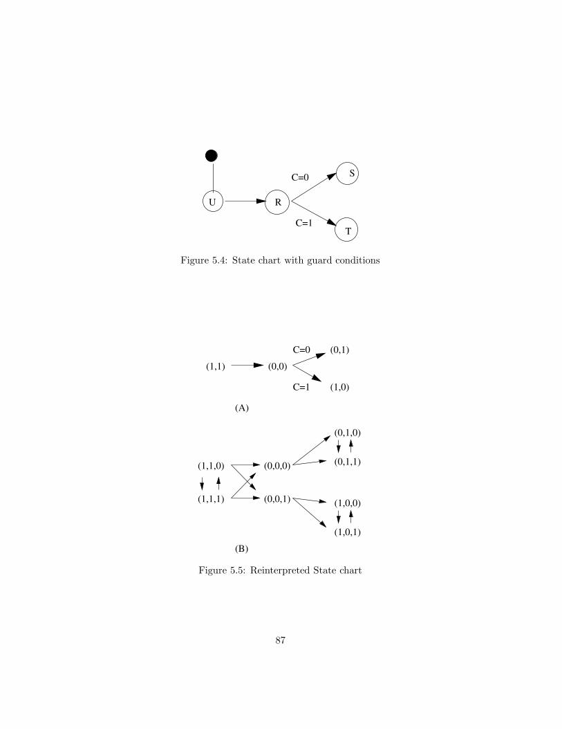
U
S
T
R
C=0
C=1
Figure 5.4: State chart with guard conditions
(1,1) (0,0)
(0,1)
(1,0)C=1
C=0
(0,1,0)
(0,1,1)(1,1,0)
(1,1,1) (0,0,1)
(0,0,0)
(1,0,0)
(1,0,1)
(A)
(B)
Figure 5.5: Reinterpreted State chart
87

Without loss of generality, assume an object with two binary attributesA,B. These span a state space of four states, namely R = (0, 0), S =(0, 1), T = (1, 0), U = (1, 1) (Fig. 5.4). Note that the guard conditions on thestate transitions (R,S) and (R, T ) introduce an attribute C. Since the statespace is spanned by all attributes of a particular model, this expands theconceivable state space to eight states: R0, R1, S0, S1, T0, T1, U0, U1 wherethe subscript denotes the values of attribute C. We can then transformFig. 5.4 to explicitly include the expanded state space as depicted in Fig. 5.5.Fig. 5.5 (A) shows the initial state chart, equivalent to Fig. 5.4, whereasFig. 5.5 (B) shows the transformed state chart. For demonstration purposes,we have written out the attribute assignments in this figure.
The resultant state chart does not contain an explicit guard condition.Instead the semantics of the guard condition are now modelled by the al-lowed state transitions.
Ontologically, a thing can be in only one current state in any givenmodel. Guard conditions are employed to specify the conditional transitionof an object from one state to exactly one of a number of others. Hence, werequire that the guard conditions for all state transitions beginning with thesame state and ending in non-concurrent region states be mutually exclusive,i.e. under no circumstances can two or more of them evaluate to true. Onlythen can it be guaranteed that the object representing the thing is not intwo states at the same time, without these explicitly being concurrent sub-states. We propose the following rule to express this. Since the elementsof guard conditions are not described in the UML meta-model, no OCLdescription can be given for this rule.
Rule 23 Guard conditions on transitions from the same state to non-concurrent sub-states must be mutually disjunct.
If this is not the case, the analyst must identify whether the two or moretarget states are actually concurrent regions of a single super-state. If that isthe case, they should be modelled accordingly and rule 22 and corollaries 15and 16 become applicable.
5.2.3 Action States
Action states in UML are states of an object during which the object un-dergoes a change. This is incompatible with the ontological notion that a
88

SubmachineStateActionState
Figure 5.6: Action states as submachine states
state is an assignment of values to attributes at a specific instance in time.However, for an ontological interpretation of action states we can build onthe interpretation for sub-states (Sec. 5.2.1). If there is change occurringwhile a thing is in a certain state, there must exist a state variable not em-ployed for the state definition and that state variable may change. Hence,this can be represented in UML in the form of sub-states. We suggest tofollow rule 24 when modelling action states.
Rule 24 Action states are super-states of a set of sub-states. The objecttransitions among these while in the action state. State charts must reflectthis fact.
Fig. 5.6 proposes a change to the UML meta-model which reflects thisinterpretation. In the current meta-model, action states are a specializationof simple states. We propose that they instead be interpreted as sub-typesof submachine states and thus composite states.
UML further allows an action construct to be associated with states.These actions are intended to represent the activity that is ongoing whilean object is in that state. Based on the above discussion, there appears noneed to assign such an action. Any activity can be described by the set ofsub-states and the transitions among them.
Corollary 17 States must not be associated with any actions. Sub-statescorresponding to different models should be used instead.
This translates to OCL as follows:
89

On Shelf
In Packing System
On Loading Dock
On Truck
Being shipped
(A)
(B)
Being shipped
Figure 5.7: Action states as super-states
(5.10)context State inv:self.entry->Size()=0 andself.exit->Size()=0 andself.doActivity->Size()=0
An example of this interpretation is shown in Fig. 5.7. The situationin (A) is equivalent to that in (B). An item that is in the action state of”being shipped” undergoes state transitions while being in that state, e.g.from state ”on shelf” to a new state ”in packing system” etc. Since action
90

states often appear in activity diagrams, this rule ensures inter-diagramconsistency between these and state charts. Because of the sub-classing ofaction states as submachine states, corollaries 15 and 16 are also applicableto action states.
5.2.4 Partitions
Partitions (”swimlanes”) are employed in UML activity diagrams to groupstates or action states together. These partitions have no further semanticsin UML, but are often featured prominently in activity diagrams. It istherefore important to examine them ontologically.
In UML, an activity diagram is a state machine and state machines de-scribe the behaviour of the objects of a single class or the implementation ofan operation (see Sec. 5.2.5 below). The elements of a partition are there-fore interpreted ontologically as states and state transitions between states.Ontologically, states are defined for a given thing and state transitions aredefined only between states of the same thing (see also Sec. 5.1.1). Giventhis ontological constraint, partitions cannot represent objects or classes ofobjects. Otherwise, state transitions that cross partitions would representstate transitions between different objects. This leads us to propose thefollowing rule:
Corollary 18 All states in an activity diagram must be states of the sameobject.
No OCL expression needs to be given, as the meta-model ensures thisrule through the specialization of StateMachine to ActivityGraph. We statethis rule for the benefit of visually modelling activity graphs.
Recall that the attributes of an object include those of its parts. Ifstates of what may appear to be different objects are included, the mod-eller or analyst must examine whether these different objects are not partsof a composite. For example, activity graphs are often used for businessprocess representations Dussart et al. (2002). State transitions between twopartitions, e.g. ”Marketing Department” and ”Production Scheduling De-partment” can be interpreted as state transitions within the single compositeobject ”Company” or ”Plant”. In that case, this composite object must beexplicitly modelling in a class diagram.
91

Corollary 19 If the partitions of an activity diagram represent differentobjects, they must be part of a composite which is shown in the class diagram.
5.2.5 Operations
The BWW-ontology provides no construct that is equivalent to methodsor operations and it has been suggested that these are an implementationrelated construct, i.e. without relevance for real-world models (Parsons andWand, 1991, 1997) and thus need not be interpreted ontologically. However,as they feature prominently in class diagrams, it is important that they begiven some ontological explanation.
Whereas operations specify behaviour only in abstract terms withoutsuggesting an implementation, a method provides just this implementationof an operation. As dynamics are expressed ontologically through statesand state transitions, these concepts must be used to interpret methods andoperations ontologically. We begin by examining the operation constructwhich is followed by a discussion of methods in Sec. 5.2.6.
Both state semantics and operations are related to the same ontologi-cal notion of change and so we require agreement between the two types ofdescription. We begin the mapping with the observation that in the objectapproach, the entire range of behaviour is determined by the set of opera-tions. Ontologically, all (quantitative) changes of a thing are describable bya series of state transitions among stable states. We therefore propose thefollowing rules:
Rule 25 The quantitative object behaviour (for each model) is entirely de-scribable by top-level state chart (SC0)
We will see below, that this top-level state chart specifies the objectbehaviour with respect to external events (see corollary 22). In terms of theUML meta-model, this rule implies that for every class there must exist atleast one top-level state chart that expresses the possible behaviour of theobjects of that class. OCL expression (5.1) already requires the state chart.We must now ensure that this is a top-level state machine, i.e. not containedin others as a sub-state.
92

Classifier
Operation
BehvaioralFeature
Feature
StateMachine
Transition
ModelElement
0..1 0..*
+realization
* 0..1
+feature +owner
*
0..1
+behavior
+context
Figure 5.8: Operations and state transitions in the meta-model
(5.11)
context StateMachine inv:self.context.oclIsTypeOf(Class)
impliesself.top.container->size()=0
Since the behaviour of objects is limited to the operations defined on theobject, and the top-level state charts of objects describe this behaviour, wepropose rule 26:
Rule 26 All UML-transitions in SC0 must correspond to an operation ofthe object which SC0 is associated with.
We propose that this rule be formalized as an addition to the UMLmeta-model (Fig. 5.8). An operation is the realization of one or more statetransition. This allows a single operation to realize state transitions intwo different models of the object. Conversely, a state transition may berealized by an operation of the object. The meta-model changes allows statetransitions not to be realized by operations. This is necessary for example
93

when the state transition is not a state transition of a top-level state chart.The discussion below will show that methods themselves can be specifiedusing state transitions and these method-internal state transitions need notthemselves be realized by operations. Otherwise, this would lead to aninfinite regress. We therefore express rule 26 in OCL as follows, making useof expression (B.11) in Appendix B:
(5.12)context Transition inv:if
self.isTopLevel()
thenself.realization->size()=1 andself.realization.owner=self.Machine().context
elseself.realization->size()=0
endif
This specifies that if a transition is a transition of a top-level state chartspecifying class behaviour, then there exists an operation that realizes itand this operation must be an operation of the same class that the statemachine is specifying the behaviour of. Note that the OCL expression (B.11)in Appendix B defines also those transitions as top-level transitions that arecontained in sub-states of a state machine specifying class behaviour.
We have suggested that the operations defined for an object express theentire range of possible behaviour. Since in our ontology everything must beable to change (either quantitatively or qualitatively), we propose rule 20:
Corollary 20 Every object must have at least one operation.
(5.13)context Object inv:self.classifier.feature
->exists(f : feature | f.oclIsTypeOf(Operation))
The BWW-ontology distinguishes among stable and unstable states.
94

Stable states are those states that are not left without some external interac-tion while unstable states are intermediate states that an object can transi-tion out of by itself. In UML, an object remains in a particular state until anoperation is invoked by some other object. As operations are realizations oftop-level state transitions, this implies that top-level state transitions orig-inate with stable states. Since all top-level state transitions originate fromtop-level states, we propose the following rule:
Corollary 21 States in SC0 are stable.
The question then becomes how to represent the notion of stability inUML. UML contains no reference to stability or instability of states. Addingsub-classes to states in the meta-model is unsatisfactory, as this cannot ex-press the semantics of external interaction through which stability is defined.However, it is possible to make use of the UML event construct.
In UML, external interaction is indicated through the event construct(see Sec. 6.2.2 below). An event may be associated with a state transitionas the trigger of that transition7. This corresponds well with the ontologicalidea that some changes, i.e. state transitions, are externally induced andothers are spontaneous. In the BWW-ontology, this is used to mark thedifference between stable and unstable states. We can transfer the notionof stability to UML by noting that with our interpretation mapping UML-events serve as indicators of external action. It is therefore possible toidentify those state transitions which are externally induced. An object isin a stable state, if all possible transitions out of that state have an associatedUML event. If there exists at least one transition out of that state that doesnot have an associated event, the state is unstable as the object can undergospontaneous, i.e. not externally induced, changes. OCL expression (5.14)defines a function that indicates whether a state is stable.
7UML models this as an aggregation. Ontologically, a transition does not consist oftriggering events.
95

(5.14)
context State::IsStable() : Boolean
result =
if self.outgoing->forAll(t : Transition |
t.trigger->Size()=1)
thentrue
elsefalse
endif
We can now express corollary 21 in OCL as follows, making use of expression(B.12) in Appendix B:
(5.15)context State inv:self.isTopLevel()
impliesself.IsStable()
Because all the states in the top-level state chart are stable, the transi-tions must be associated with events:
Corollary 22 All UML-transitions in SC0 must be associated with a UML-event.
Using expressions (5.14) and (B.11) in Appendix B we can express corol-lary 22 in expression (5.16):
96

Car
SpeedRPMGear
StartStopForwardHalt
Forward
RunningStoppedStart
Stop
HaltForward
(A) (B)
Figure 5.9: Class definition and state chart
(5.16)
context Transition inv:if
self.isTopLevel()
thenself.trigger->size()=1
endif
The above rules and corollaries allow the modeller to identify operationsthat may have been missed in constructing the class diagram or identifyoperations for which there are no corresponding state transition. Such op-erations are redundant. Fig. 5.9 shows an example. Consider a car that canbe in three states, stopped, (engine) running and going forward. Assumethat the states of a car are defined as follows:
Stopped (Speed = 0, RPM = 0)
Running (Speed = 0, RPM = 1000, Gear = 0)
Forward (Speed = 50, RPM = 3000, Gear = 1)
The class definition (A) is consistent with the top-level state chart SC0
depicted in (B).
97

In addition to these rules, we remind the reader of rules 4 and 5 in thecontext of association classes that are applicable to operations as well.
The benefit of explicitly modelling the link between operations and statetransition is to give the method designer some way of ensuring that thefull state description of a system is realized. It also helps ensure that themethods and operations do not implement any change beyond that containedin the state description. Such additional behaviour could cause a faultyinformation system.
To summarize, both operations and state charts are linked to the sameontological concept of change and can be linked through state semantics. Weconclude this section with an examination of the implications of qualitativechange.
Operations and Qualitative Change
The complete behaviour of an object is defined by its operations and this be-haviour must express the total possible change of the represented thing. Bycorollary 12 we know that qualitative change occurs within a generalizationhierarchy. In other words, in order for qualitative change to occur, theremust exist a super- or sub-class. However, since qualitative change involvestwo distinct state spaces or models, it cannot be described by state transi-tions (Sec. 5.2.8). Hence, in the case when a super- or sub-class of particularclass exists, and qualitative change is possible for a thing represented by anobject of said class, an object must possess additional operations that ex-press qualitative change. These operations are not included in those definedto satisfy rule 25. That rule is applicable only to quantitative change.
Rule 27 An object must exhibit additional operations expressing qualitativechanges, if a super- or sub-class is defined and instances can undergo changesof class to the super- or sub-class.
The discussion in Secs. 4.2.3 and 5.2.8 shows that qualitative change ischaracterized primarily by loss or acquisition of behaviour, represented byoperations and state charts. In OCL, this leads us to require that if and onlyif there exists a super- or sub-class there must exist at least one operationnot associated with a state transition expressing re-classification. At most,there exists one such operation for every sub- and super-class. We say ”atmost” because it may not be possible for a thing to loose properties once ithas acquired them.
98

(5.17)context Class inv:if self.child->size() + self.parent->size() > 0
thenself.feature
->select(f | f.oclIsTypeOf(Operation) andf.realization->isEmpty())
->size() > 0
andself.feature
->select(f | f.oclIsTypeOf(Operation) andf.realization->isEmpty())
->size() =< self.child->size() + self.parent->size()
endif
5.2.6 Methods
Operations are not the atomic units of behaviour in UML, but are realizedby methods. Section 2.3 discussed the concept of a lawful transformation asa ’path’ in state space between an initial and a final state and noted thatthere may exist many such lawful transformations for each pair of initial andfinal states. With the interpretation of UML operations as state transitions,this leads to the mapping of methods to lawful transformations. Hence, amethod describes a lawful ’path’ through state space. This path begins inthe source state of the state transition represented by the operation whichthe method implements.
Methods themselves can be described by state charts. The UML meta-model allows the modeller to associate state machines with behavioural fea-tures, which are either a method or an operation 8:
Rule 28 Methods may be described by state charts other than top-level statecharts.
A lawful transformation may or may not be expressible by a series of state
8Here and in many other places, the UML meta-model specifies an aggregation asso-ciation, which is ontologically incorrect. For reasons outlined in Sec. 2.6 above we refrainfrom changing this.
99

transitions. If the transformation represents change of a continuous variable,as is often the case, a series of state transitions can only approximate thepath in state space. However, if the change is discrete and there does exista state chart describing the corresponding method, this state chart mustfollow some rules, developed presently.
We can think of methods as representing lawful transformations which’implement’, i.e. describe in greater detail, a state transition representedby an operation. As such, the beginning and end of the path in state spacerepresented by a method must match the initial and final states of that statetransition. We therefore propose rule 23:
Corollary 23 A state chart describing a method must begin and end withthose states in SC0 which the operation that the method implements is arealization of.
To state this in OCL, we make use of initial pseudostates and the factthat final states of a state machine are an explicit subclass of states. Thecorresponding OCL expression to the above rule then reads as follows:
(5.18)context StateMachine inv:self.context.oclIsTypeOf(method)
impliesself.top.subvertex->select(sv :
sv.oclIsTypeOf(State)
andsv.incoming.source.oclIsTypeOf(Pseudostate)
andsv.incoming.source.kind="initial")
= self.context.specification.transition.from
andself.top.subvertex->select(sv :
sv.oclIsTypeOf(FinalState))
= self.context.specification.transition.to
Moreover, since a method is a more detailed description of an operation,it must be true that it is caused by the same event that causes the operation.This motivates the following corollary:
100

Corollary 24 State transitions out of the initial state of a method realizingan operation must be associated with the same event that is associated withthe transition in SC0 which represents that operation.
(5.19)context Operation inv:self.method->forall(m : method |
m.behaviour->exists()
impliesm.behaviour.top.internalTransition
->select(tr : tr.source.incoming.source
.oclIsTypeOf(PseudoState)
andtr.source.incoming.source
.kind="initial")
.trigger
= self.realization.trigger)
endif
Since the UML meta-model allows the association of one model elementwith any state machine, we suggest that this model element is either aclass, in which case the state machine describes the top-level behaviour, ora method, in which case the state machine describes the method. If a statemachine is not associated with any model element, it describes a compositestate contained which defines sub-states.
Corollary 25 A state chart either expresses the external behaviour of anobject (SC0), a method, a signal reception or is a composite state containedin another state machine.
101

(5.20)
context StateMachine inv:if notself.context->isEmpty()
thenself.context.oclIsTypeOf(class) orself.context.oclIsTypeOf(method) orself.context.oclIsTypeOf(reception)
elseself.SubMachineState->isEmpty() = false
This specifically precludes the association of operations with state-machines. If an operation is implemented by a method then this methodmay be associated with a state machine. If the method defines continuouschange between two states, it cannot be described by a discrete state ma-chine. In that case, the state transition that is realized by the operation isan adequate description of change and no state machine is necessary. Wetherefore suggest the following rule and corollary:
Rule 29 An operation is not directly specified by state machines. Instead,the methods that implement operations are specified by state machines.
(5.21)context Operation inv:self.behaviour->size()=0
Furthermore, we propose that state machines which express the be-haviour of objects or of methods must not be contained is composite sub-states in other state machines. The following corollary and OCL expressionensures this:
Corollary 26 A state machine that specifies the behaviour of a class or amethod is not contained in other state machines.
102

(5.22)context StateMachine inv:self.context.isEmpty() = falseimpliesself.SubmachineState
->forall(sms : SubmachineState |
sms.Container->size() = 0)
Rule 28 and corollaries 23, 24 allow the modeller to identify incompleteor redundant state charts and methods: If a method is not associated with astate chart, it may be redundant or it represents a form of continuous changenot expressible using discrete change concepts. If a state chart describing amethod does not begin and end with the proper states, it may be incomplete.
The BWW-ontology requires that each state transition must change thevalue of at least one attribute (see Sec. 2.2). This motivates the followingrules:
Corollary 27 The method corresponding to a state chart must modify theattribute values of the object corresponding to the values defined for the initialand final state of the method.
The adoption of this rule will help to design and specify methods thatconform to the state description by ensuring the modeller or designer isprovided with exact specifications of the pre- and post-conditions of anymethod. With the help of the meta-model we can determine the attributevalues before and after the execution of a method.
(5.23)context Method:
let preAttributes
= self.specification.transition.source.slot.value
let postAttributes
= self.specification.transition.target.slot.value
103

OperationReception10..1
Figure 5.10: Meta model linking signal reception to operations
5.2.7 Signal Reception
This section examines the UML reception construct in terms of ontologicalconcepts. UML provides the construct of a signal reception to specify whichUML-signals objects of a certain class can receive and react to. A receptionis a behavioural feature like operations and methods.
All behavioural description in UML must be mapped to states and statetransitions of the BWW-ontology. UML behaviour already mapped includestate charts as well as operations and methods. Receptions form yet anotherway to express externally induced behaviour and must also be mapped tostate transitions. However, receptions do not provide anything that couldnot be expressed before. Both operations and state transitions can be as-sociated with events which trigger them. For these reasons, the receptionconstruct is redundant in UML.
If receptions are being used by the modeller, there must exist modellingrules which ensure consistency in their use. We suggest that every signalreception correspond to exactly one operation. This is shown in the proposedaddition to the meta-model in Fig. 5.10 and made explicit in the followingrule:
Rule 30 An operation must be associated with the declaration of signal re-ception.
Since a signal reception and the operation specify the same ontologicalbehaviour, they must be triggered by the same external event. We thereforepropose:
Rule 31 The event associated with an operation must be identical to theevent associated with the signal associated with the reception.
104

(5.24)context Reception inv:self.operation.transition->forall(t : transition |
t.trigger = self.signal.occurrence)
Moreover, an operation is specified or implemented by a method. Themethod in turn may be associated with a state machine which providesdetails about it. On the other hand, a reception can also be associatedwith a state machine. Operation and signal reception specify the sameabstract behaviour, i.e. both specify the same initial and final state, but notnecessarily the same path in state space. Thus, instead of requiring that anoperation and a reception be associated with the same state machine, wemake a weaker requirement:
Corollary 28 The state machines associated with a reception and with amethod specifying the implementation of an operation which is in turn asso-ciated with that reception, must possess the same initial and final states.
We can formalize this using OCL expressions (B.18) and (B.19) in Ap-pendix B to propose the following invariant on signal receptions:
(5.25)context Reception inv:self.signal.event->forall(e : Event |
e.transition->forall(t : transition |
self.behaviour.allInitialStates()
->includes(t.source)
andself.behaviour.allFinalStates()
->includes(t.target)))
Methods, operations and declarations of signal reception are behaviouralfeatures. All of them may be associated with a state machine that describestheir behaviour. Additionally, an operation is implemented by a method anda signal may also trigger a state transition. Fig. 5.11 shows the relationshipsamong these constructs. Thus, UML provides three different ways to expressdynamic behaviour, while the BWW-ontology provides only one way.
105

State Chart
Method
Signal ReceptionOperation
describes
implements
describes
proposed
Figure 5.11: Relationships between behavioural constructs in UML
The rules developed in this section give the modeller some guidelines inhow to design operations and methods that correspond to behaviour speci-fied in state machines or state charts. Thus, they help ensure correct systemspecification and system behaviour.
5.2.8 Specialization and Changes of Class
A major problem with specialization is the question of how behaviour, i.e.state machines are specialized. The fact that every instance of the specialclass is also an instance of the super-class implies that any instance of asubclass may be behaviourally substituted for an instance of the super-class.It must exhibit the same behaviour as an instance of the super-class. Whatdoes ’the same behaviour’ mean in this context? Prior research (Lakos andLewis, 2000; Harel and Kupferman, 2000; Schrefl and Stumptner, 2002) hasexamined this question and proposed rules or guidelines to this effect.
However, none of the past studies considered the integration of behaviourwith static structure as exhibited in the BWW-ontology through the def-inition of states as vectors of attribute values. This integration allows usto identify two criteria for behaviour specialization. The first criterion fo-cuses on substitutability of a sub-class instance with respect to a single statetransition:
1. State definitions in terms of attribute values may be interpreted aspre- and post-conditions for state transitions. Hence, state transitions
106

S1 S2X1:
X2:
X1:
X2:
Figure 5.12: Behaviour specialization: States of A
A
a
X1X2
Figure 5.13: Behaviour specialization: Class definition A
in derived sub-classes must conform to these conditions.
Condition (1) is necessary but not sufficient for proper specialization,since it does not guarantee substitutability for sequences of state tran-sitions. We therefore add the following condition (2):
2. Behavioural substitutability means that a derived sub-class can un-dergo the same sequences of top-level state transitions as the baseclass. Equivalently, the derived sub-class can undergo the same seriesof operations than the base class.
Consider a class A defined with attribute a and two operations, x1 andx2. Let two states be defined for instances of A: s1 =< a = 1 > ands2 =< a = 2 >. This is shown in Fig. 5.12 and Fig. 5.13 respectively. Thetwo operations are associated with state transitions between s1 and s2. Thestate definitions serve as pre- and post-conditions for the operations.
Consider now a specialization of class A by sub-class B, defined inFig. 5.14. The specialized behaviour, i.e. the top-level state chart of B
must conform to the two criteria outlined above. Figs. 5.15, 5.16 and 5.17show some state charts that fulfill these criteria. In order to simplify thediagrams, we have named the states so as to show their definition in termsof attribute values.
107

A
a
X1X2
B
b
Figure 5.14: Behaviour specialization: Class definition B
a=1, b=1
a=2, b=2 a=1, b=2
a=2, b=1
X1:
X2:
X1:
X2:
X1:
X2:
X2:
X1:
Figure 5.15: Behaviour specialization: Possible state chart of B
a=1 a=2
b=1 b=2
x1:
x2:
y1:
y2:
x1:
x2:
y1:
y2:
Figure 5.16: Behaviour specialization: Possible state chart of B
108

a=1 a=2
b=1
b=2
b=1
b=2
x1:
x2:
y1: y2: y1:
x1:
x2:
y1: y2: y1:
Figure 5.17: Behaviour specialization: Possible state chart of B
Note that in the state chart in Fig. 5.15 the methods x1 and x2 are eachassigned to two state transitions. Depending on the value of attribute b,these methods have different effects. This may be expressed in the methoddescription e.g. through guard conditions and may require overloading theinherited method in an IS implementation. On the other hand, the methodmay only modify the values of attribute a.
The diagrams in Fig. 5.16 and 5.17 introduce new state transitions whichmust be realized by an operation. Hence, two new operations, y1 and y2are required in the definition of class B which are not defined in the modelof Fig. 5.14.
As a more concrete example, consider a customer whose relevant statesare defined in terms of an attribute ’OrderVolume’. Assume two relevantstates A and B, defined by ’OrderV olume < $100’ and ’OrderV olume ≥$100’ respectively. Further assume a possible state transition between thesestates. The two state definitions are now invariant constraints which mustbe satisfied by all customers that undergo this state transition.
Now assume a special kind of customer, e.g. ’VIP Customer’. In order tobe behaviourally substitutable, a ’VIP Customer’ must be able to undergothe same state transitions, i.e. changes in the value of ’OrderVolume’ mustsatisfy the same conditions. However, assume that the ’VIP Customer’ pos-sesses another attribute expressing the ’Volume Discount Rate’ and let thisbe dependent on the ’OrderVolume’. Then a state transition from a stateC defined by ’OrderV olume < $100’ and ’Volume Discount Rate = 10%’
109

to state D defined by ’OrderV olume < $200’ and ’Volume Discount Rate= 20%’ is considered behaviourally substitutable as it does not violate theconstraints given by the state definitions. Beyond this redefined transition,the ’VIP Customer’ may of course exhibit additional behaviour in the formof additional state transition that she can undergo.
Research by Schrefl and Stumptner (2002); LeGrand (1998) argues alongsimilar lines of reasoning. Schrefl and Stumptner (2002) focus primarily onbehavioural substitutability in the sense of our criterion (2) above, whereasLeGrand (1998) also considers the fact that states are linked to static struc-ture attributes and their values. The three example state charts shownabove conform to results derived in LeGrand (1998). This agreement of anontological argument with prior research lends further support to both theontological semantics and the prior research.
Acquisition of Properties The BWW-ontology suggests that additionalproperties appear as a result of interaction of a thing with other things. Thisleads to specialization of things in terms of structure (the additional acquiredproperties) and behaviour (the state changes now possible). There exist twogeneral cases of property acquisition, depending on the relationship of theacquired attributes to the existing ones.
1. Acquisition of independent properties
Harel (1988) introduces orthogonal regions in state charts as contain-ing concurrent sub-states, i.e. a thing is in two states at the same time.Sec. 5.2.1 shows that concurrent sub-states require mutually disjunctsets of attributes which span the orthogonal regions of the state space.Harel (1988) advocates the use of such orthogonal regions in order tomitigate the problem of exponential growth of the number of statesthat is experienced in state transition diagrams when state variablesare added.
In the case of independent properties, the additional properties span anindependent (orthogonal) subspace of a things state space. Thus, it ispossible to employ the construct of orthogonal regions of state chartsto support this type of property acquisition. We therefore proposerule 32 which reflects this:
Rule 32 Acquisition (loss) of independent properties leads to expan-sion (contraction) of a thing’s top-level state space SC0 by an orthog-onal region.
110

A
a
x1x2
B
b
C
c
Figure 5.18: Example specialization
If the acquired properties are independent of existing ones, then bycorollary 16 (orthogonal regions defined by disjunct attribute sets) it isthese and only these that span the new orthogonal region. This agreeswith the two criteria regarding behavioural substitutability set forthabove: Sub-classes that exhibit independent additional properties arebehaviourally substitutable, as the new behaviour is independent ofthe existing behaviour.
2. Acquisition of non-independent properties
In the case of acquisition of new properties that are not independent,the existing state-space is redefined and generally the entire state ma-chine description of the object must be re-developed ab initio.
This may not be necessary in certain cases and it may be possible todevelop the derived state machine based on the state machine descrip-tion for the more general class.
Consider the situation depicted in Fig. 5.18 showing a general classA with attribute a and two operations x1 and x2. There exist twospecialized sub-classes B and C which inherit attribute a and defineadditional attributes b and c. Assume that the domain of a is the set{B,C} and that for instances of B, a = B and for instances of C,a = C. The value of attribute a then determines not only the state ofthe instance, but also the sub-class of the instance.
111

a=B a=Cx1:
x2:
x1:
x2:
Figure 5.19: Example specialization: State chart
a=B a=C
b=1
b=2
c=1
c=2
Figure 5.20: Example specialization: Derived state chart
Assume that the state description of instances of A is as shown inFig. 5.19. Then, according to the above criteria for substitutability,only a state machine description like the one in Fig. 5.20 will be valid.Notice that the attribute b is only present when a = B. This inturn implies that the state chart of instances of B will be a sub-statemachine contained in state a = B. Similarly, the state machine forinstances of C will be a sub-state machine contained in a = C. Thus,in the case where a change in an attribute (or a change in state) isalso a change in sub-class, the state machine descriptions of the sub-classes need not be completely be re-defined but are merely a sub-statemachine within a more general state description.
An example for this kind of specialization is that of a set of studentsattending a university. On the level of the students, there exists a prop-erty ’ProgramEnrolledIn’ which can take on the values ’Undergrad’,’Grad’, etc. Depending on the value of the attribute representing thisproperty, the students can be sub-classed into the classes ’Undergrad-Student’, ’GradStudent’ etc. which in turn possess different attributes
112

Undergrad Graduate
Alumnus
Figure 5.21: Example specialization: Student state charts
such as ’Major’ and ’Minor’ for undergraduate students, ’NameOf-Supervisor’ for graduate students etc. while all students may possessproperties such as ’TuitionBalance’, ’CreditsAccumulated’, etc. In thiscase, the properties ’Major’ and ’Minor’ are only present in instancesfor which ’ProgramEnrolledIn’ is equal to ’Undergrad’. Thus, statesthat depend on the values of ’Major’ and ’Minor’ are only defined forundergraduate students and can therefore only be substates of studentstates for which ’ProgramEnrolledIn=Undergrad’.
For practical modelling we suggest that the state chart for each sub-class includes the relevant states of the general class and show thestate refinement for that particular sub-class of instances. Figs. 5.21,5.22 demonstrates this for the student example.
With this discussion of qualitative change, we are now in a position tofurther formalize the conditions of changeability imposed on UML by themapping of BWW concepts. The BWW-ontology requires that every thingmust be able to change. This implies that either it can undergo a quantita-tive change or a qualitative change. In order to undergo qualitative change,by rule 12 which states that qualitative change occurs within generalizationhierarchies, a class must either possess a more general super- or specializingsub-class. This motivates the following rule, expressing this:
Corollary 29 Every object must be capable of at least one state transitionor be able to undergo change of class to a super- or sub-class.
With the help of expression (B.13) in Appendix B we can state thisrequirement in OCL:
113

Undergrad
Graduate
Alumnus
Full Time Part Time
Figure 5.22: Example specialization: Undergraduate student state charts
(5.26)context Class inv:self.child->size() > 0 orself.parent->size() > 0 orself.behavior
->exists(sm : StateMachine | sm->OneTransition())
5.3 Summary
This chapter examined the notion of change both from the ontological per-spective (representation mapping) and, with that mapping in mind, fromthe perspective of UML (interpretation mapping). We have mapped BWW-states and BWW-state transitions directly to corresponding UML constructs.Other UML constructs have required a more elaborate interpretation. Ta-ble 5.1 shows the ontological interpretations of the concepts and constructsdiscussed in this section.
The table shows that the basic ontological concepts have direct UMLequivalents and this mapping relation is again made bijective by the pro-posed rules constraining the use of the UML constructs. We have noted thatthe description of change in UML through the use of methods and, at the
114

OntologicalConcept
UML Construct Remarks
State State Connection withattribute made
State State Machine UML allows nestedsub-states
State Sub-state dto.
State Action State Action states aresuper-states
Transition Transition
Transition Operation
Lawful transformation Method
Law Guard condition
Partition
Reception
Table 5.1: Summary of Interpretations Related to Change
same time the use of state charts, may be ontologically redundant as it mustbe mapped to the same ontological concepts. This allowed us to proposesome rules to keep these two concepts of change consistent. Similarly, thediscussion of signal receptions has shown that these may be ontologically re-dundant. Again, if used, the modeller must obey rules to ensure the model’soverall consistency.
115

Chapter 6
Interaction
In previous chapters we have discussed static structure (Chap. 4) and changewithin a thing or object (Chap. 5). This section is now concerned withthe interaction of two or more things. We will discuss this first from theontological perspective and then from the UML point of view.
6.1 Representation Mapping
The BWW-ontology does not provide constructs or concepts specifically forthe description of interaction. Instead, interaction is defined through statetransitions which have already been discussed in Chapter 5. Two or moreobjects are said to interact, if and only if the state transitions that eachobject undergoes depend on the existence of the other object. The possiblestates and transitions are constrained by laws and hence, interactions canin theory be derived from the knowledge of the laws1.
6.1.1 Interaction & Laws
This section will examine how interactions are caused by laws and how,depending on the laws, a particular state transition may give rise to inter-action, i.e. be mapped to a UML-event or UML-action.
1We say ’in theory’ because for practical purposes this requires methods such as con-straint solving (Mackworth, 1977) or constraint programming (Van Hentenryck, 1989)which are not generally applicable and, except for special cases, not computationally effi-cient, i.e. not of polynomial computational complexity.
116

Ontologically, interaction is described by state histories. When the statehistory of one thing depends on the existence of another, there exists inter-action. This is not a mechanism of interaction. Interaction arises becausethings adhere to laws that must be satisfied at all times: When an event inthing A changes a property which is lawfully related to a property of thingB, the property of thing B must adjust so that the law remains satisfied2.Thus, interaction is a primary concept in UML and the object approach (inthe sense that it is directly specified, not derived), it is derivative in ontol-ogy: Interaction can be deduced from properties and the laws that relatethem to one another.
Object-oriented approaches express interaction through message-passing.However, any given message passing pattern is simply one specific way ofsatisfying the laws and there may be
1. other mechanisms beside messages passing or
2. other patterns of messages that also satisfy the laws.
The ontological nature of message passing is discussed in Sec. 6.2.1 belowas part of the interpretation mapping.
In general, it is the system designer’s task to ensure that the modelledmessage-passing pattern satisfies all laws. Hence, message-passing and themodelling of message-passing is a design oriented task. It is often the casethat such laws are not explicitly stated, but only implicitly understood bythe analysts. Our ontological evaluation can help by explicating the exis-tence of laws or constraints and suggesting possible ways to use message-passing to satisfy the laws. In sum, the BWW ontology supports a de-scriptive and declarative style of modelling whereas the object-oriented ap-proach is more prescriptive and procedural. This is not surprising as earlyobject-oriented approaches were rooted in procedural programming. Earlyobject-oriented programming systems were pre-processors that would trans-late object language code, e.g. C++, into corresponding procedural code,e.g. in C. Methods were realized by implementing pointers to function inthe same structure as variables (attributes of objects).
We use the remainder of this section to examine when and how interac-tion should be modelled. We do this before the background of the message
2Note also that an information system (or any artificial system) is always in a lawful
state. However, this state may be undesirable to the IS designer and so is a symptom ofa design fault.
117

passing paradigm that is prevalent in object-oriented approaches and UML.Specific UML constructs will be discussed in the following interpretationmapping.
In the discussion of the BWW-ontology in section 2.3 we remarked thatsince laws constrain the state variables of only a single thing, changes amongtwo things must happen by virtue of mutual properties. If the two things areparts of the same composite, changes among them may happen by virtue ofemergent properties. Thus, a change in one thing not only leads to a changein another thing but is a change in another thing. Only one property ischanged by a state transition in one thing and this change is a change of thesame property in the other thing and thus is a state transition in the otherthing.
With the mapping of mutual properties to association class attributes,this discussion leads us to propose the following rule for modelling interac-tion in UML:
Rule 33 For every two classes of objects between which message passing isdeclared, there exists an association class or the two classes are parts of thesame aggregate.
In OCL, making use of expressions (B.6) and (B.7) defined in Appendix B:
(6.1)context Message inv:self.sender.base.allProperties()
->exists(p : attribute |
p.owner.oclIsTypeOf(AssociationClass)
andself.receiver.base
.allProperties()->includes(p))
orself.sender.base.partOf()->intersect(
self.receiver.base.partOf())
->isEmpty() = false
This rule is helpful for the modeller to identify which messages need tobe shown in a model and between which two object an association classneeds to be identified.
118

There are some situations when this rule may need to be relaxed in prac-tice. It is not always possible nor desirable to model intermediate objectssuch as communication systems. Instead, these are often taken for grantedas they are outside the scope of the system. For example, a telephone linebetween two people possesses mutual properties with both the speaker andthe listener. It is these mutual properties and the properties of the phoneline (voltage, waveform, etc.) which undergo change. In practice, the tele-phone line and it’s properties will not be included in the model and insteadbe assumed implicitly.
Bunge (1977) proposes that every thing acts on and is acted upon byother things. This means that there must exist some interaction originatingand terminating in any particular thing:
Rule 34 Every object must be the receiver and sender of some message.
While this is a very strong requirement, it shows the need to criticallyexamine the interactions or information flows. One could argue that thingsin a system’s environment may only send but not receive messages, e.g. acustomer ordering a product, a student registering for a course, etc. Buteven for these examples, the actions of ordering and registering are pointlessunless the customer and the student also receive messages. This could beorder acknowledgements or shipping details for the customer. For the stu-dent, the messages may involve tuition fee billing or text book requirementmessages. In other words, neither the customer nor the student will onlysend messages without receiving any. Note also that messages in UML aremore general than information, but represent the change of mutual prop-erties. Thus, the customer receiving the shipment and the student beinginvoiced the tuition fees is also represented by messages.
Often, a thing is an aggregation of parts. In such cases, it is sufficientif the aggregate or any of its parts receive and send some message. The re-ceiving and sending must not necessarily be done by the same part. Assumethere exists an aggregate a with parts p1 and p2. If p1 receives messagesbut does not send any and p2 sends messages but does not receive any, weconsider rule 34 to be satisfied, as the aggregate a both receives and sendsmessages. With this, the above rule 34 can be expressed in OCL as follows,making use of expressions (B.5) and (B.7) defined in Appendix B:
119

(6.2)context Class inv:self.allParts()
->union(self.partOf())->exists(cls : Class |
cls.ClassifierRole->exists(clr : ClassifierRole |
clr.sender->size() > 0)) andself.allParts()
->union(self.partOf())->exists(cls : Class |
cls.ClassifierRole->exists(clr : ClassifierRole |
clr.receiver->size() > 0 ))
This OCL expression specifies that some part of a class or some aggregateof which the class is part of (or their generalized super-classes from whichthey inherit) plays the role of sender of a message and some other part of aclass or some other aggregate of which the class is part of plays the role ofreceiver of a message.
This implies by rule 33, that there exist mutual properties or emergentproperties of common aggregates that relate any one thing to some otherthing. Moreover, these must exist before the message is passed. In mostpractical situations, these are mutual properties of intermediate objects thatmay be omitted, such as the telephone line in the example above.
As association classes are interpreted as representing bundles of mu-tual properties, not substantial things, they can be part of interaction onlyby being changed as part of change in the objects of participating classes.They represent the things possessing the mutual properties undergoing thatchange. Association classes do not represent things that are capable ofchange. Furthermore, rule 4 suggests that behaviour should be modelledwith the participating classes. This leads us to propose the following rule:
Corollary 30 An association class cannot be the sender or receiver of amessage.
Hence, association class instances cannot interact with other instances,reflecting the fact that in ontology mutual properties do not interact, thatit is the things possessing them that interact. As an example, consider themutual property of a salary of an employee with a company. While theemployee and company are substantial things that can interact, the salary
120

is a property that cannot interact, even though it may be changed as partof changes in either the employee or the company (e.g. when the companypromotes the employee and raises the salary). In OCL:
(6.3)context Message inv:not self.sender.base.oclIsKindOf(AssocationClass) andnot self.receiver.base.oclIsKindOf(AssociationClasse)
Laws
UML provides the construct of a constraint. A constraint relates two ormore elements of a model and restricts their value. We propose to map aconstraint to a BWW-law. For this to be a valid mapping, we must restrictUML-constraints to relating attributes of the same object, i.e. declaredwithin the same class. Rule 35 ensures this:
Rule 35 A constraint relates attributes of a single class or attributes ofassociation classes the class participates in.
In OCL this is described by the following OCL expression (6.4), makinguse of expression (B.14):
(6.4)
context Constraint inv:self.constrainedElement->forall(c1, c2 :
c1 <> c2 andc1.oclIsKindOf(Attribute) andc2.oclIsKindOf(Attribute) and( c1.propertyOf()->includes(c2.propertyOf()) orc2.propertyOf()->includes(c1.propertyOf()) )
121
6.2 Interpretation Mapping
This section examines the UML constructs and concepts that are related tointeraction, while keeping in mind that these must be interpreted in terms ofstate transitions and laws. The central concept of object-oriented interactionis that of message passing. We begin this section by examining the languageconstructs that UML provides to support this interaction paradigm.
The discussion of the BWW-ontology in section 2.3 showed that all prop-erties are lawfully related to others. We therefore propose the following rule:
Rule 36 For every attribute there exists a constraint which relates this at-tribute to some other attribute.
For example, the throughput of a machine is constrained by its possibleinput, by the production schedule, by the material of the parts it works on.Similarly, the expected quarterly profit is constrained by economic expecta-tions of the management team, the number and productivity of the groupof employees comprising the company and many other factors. In general,there exists no property that can be freely changed without affecting orbeing affected by constraints that relate it to other properties.
As constraint conditions are not decomposable in the UML meta-model, thisrule cannot be expressed in OCL.
6.2.1 Message Passing
Message passing is one of the core concepts of the object-oriented approach.Message passing is the mechanism by which object interaction and objectcommunication is realized. UML supports message passing through a num-ber of constructs. Stimuli (instances of messages) are passed along links (in-stances of associations) between objects (instances of classes). The stimulusspecifies the nature of the communication, i.e. which operation to invoke orwhich signal to raise. A stimulus is created and sent by an action. Receiptof a stimulus is an event. Different actions may create different stimuli. TheUML meta-model does not explicitly sub-class the stimulus construct. Theclass of stimulus is determined by the associated action that created it:
• Call action – Synchronous or asynchronous method invocation
• Send action – Results in the (asynchronous) sending of a signal
122

• Create action – Creation of an instance of some class
• Destroy action – Destruction of the target object
• Return action – Returning a value to the sender of the call action
• Terminate action – Results in the self-destruction of an object
• Uninterpreted action – Any other action which has no interpretationin the UML meta-model
The first four of these actions create a stimulus for inter-object com-munication. While the create action does generate a stimulus, UML doesnot associate a target object with a create action. The last three do notcreate a stimulus. In the UML meta-model a stimulus is associated with theaction that dispatches it. Hence, there is no need to explicitly associate astimulus with a signal (of which it may be a carrier) or an operation (whoseinvocation it may signify), as the sub-class of the dispatching action deter-mines what effect the stimulus will have. Since objects, with the ontologicalinterpretation of things, cannot be destroyed or created, there is no creatingor destroying thing that a stimulus could be sent to. Hence, only the firsttwo of these actions are relevant to the interpretation of message-passing.
Stimuli can be interpreted in two ways, depending on the ontologicalstatus we ascribe to them:
• Stimuli are not things in the world. They are abstract concepts thatserve as descriptions, illustrations, abstractions or representations ofinteraction.
• Stimuli are substantive things in the world. They are ontologicallyreal.
There are two main arguments against the second interpretation. First,consider messages or stimuli such as:
• The machine sends a message to a part to change its location.
• The general ledger sends a message to an office desk to depreciate itsvalue.
• A truck sends a message to the crate asking it to load itself onto theloading dock.
123

Such messages among objects have not been observed in the real world.Instead, we find that machines interact with parts to change their location,rather than sending a message. General ledgers do not send messages, butcompanies depreciate the value property of inventory and forklift operatorsinteract with forklifts and crates and thus change the latter’s location. Nomessages are sent in this case either. In special circumstances, we maysee message passing in the real world, e.g. between two human actors orbetween interconnected machines or information systems. This is messagepassing in a much more special sense than the message passing in the objectparadigm, which is used to describe any kind of interaction. This argumentconfirms indications that messages may be a construct related more to ISdesign than the real world, as suggested by Wand (1989); Parsons and Wand(1991); Wand and Weber (1993).
Second, if stimuli were real things in the world, then instead of two ob-jects interacting directly, one object would have to interact with a stimulus,which in turn would need to interact with the second object. This onlydefers the problem to the interaction of a stimulus thing with another thinginstead of the two original things.
This discussion showed two reasons against interpreting stimuli as onto-logically real and we therefore consider stimuli as conceptual abstractions ofinteraction, not as things.
6.2.2 Stimuli, Actions & Events
With the ontological status of message-passing in mind, the following para-graphs examine various UML constructs related to message-passing. Webegin the discussion by interpreting stimuli, actions and events before pro-ceeding to the special cases related to signaling or method calling.
Stimulus
A stimulus is an instance of a message that is sent between two objects, i.e.it has a sender and receiver. It is dispatched by an action and travels alonga link. It forms the mechanism of interaction.
The BWW ontology does not specify any mechanism for interaction, al-though all laws must be satisfied at all times3. Given the above discussion,
3While there exist techniques in IS design and implementation that allow the same (e.g.
124

we propose that stimuli have no equivalent in ontology and hence are onto-logically excessive. Since a stimulus is not ontologically real, there is alsono ontological equivalent to a message, the specification of a stimulus.
Actions
A UML-action is the creation and dispatch of a stimulus. Since the previousparagraphs interpret stimuli not as ontologically real but as an abstractdescription of interaction, a UML-action is similarly interpreted as changein one object that brings about a change in another object. In the BWW-ontology this kind of interaction occurs when a BWW-state transition inone thing changes a mutual property of two things, thus also being a changein the other thing, since mutual properties span the state space of both4.
Hence, we map a UML-action to the ontological concept of a BWW-state transition, specifically a state transition in the acting thing. With theinterpretation of mutual properties as association classes (Sec. 4 we can thenformulate the following rule, which is limited to quantitative change:
Corollary 31 A UML-state transition associated with an action must mod-ify an association class attribute’s value or an emergent property of an ag-gregate.
With the help of OCL expressions (B.16) and (B.17) in Appendix B wecan define the following OCL expression to formalize rule 31:
(6.5)context Transition inv:self.action->exists() and notself.isTopLevel()
impliesself.changesMutualProperties() orself.changesEmergentProperties()
constraint programming, constraint solving techniques (e.g. Mackworth, 1977; Van Hen-tenryck, 1989)) in most object-oriented techniques the designer is responsible for specifyinga suitable mechanism for ensuring the satisfaction of all laws at all times.
4See also Sec. 6.1.1
125

We restrict this rule to UML-state transitions in method descriptions,i.e. we exclude those in top-level state charts, because operations may leavethe object in the same state or in a state in which at least the mutual oremergent properties possess the same values. This however cannot be thecase in the more detailed decomposition of such a top-level state transitionin a method.
Events
Section 5.2.5 mapped UML-events to the ontological concept of a state tran-sition. Given that the dispatching UML-action of a stimulus is mapped to astate transition in the acting thing, we propose that a UML-event signifyingreception of the stimulus be mapped to a BWW-state transition in the thingacted upon. It is that state transition in the acted upon object which corre-sponds to the changes in the mutual property caused by the correspondingUML-action.
With this interpretation, the following corollary relates interactions tothe state charts of the interacting objects:
Corollary 32 For every interaction between UML-objects, there must exista corresponding UML-state transition in both interacting UML-objects.
Like corollary 31, corollary 32 is applicable to quantitative change only.Separating the interaction into action and event, we can formulate the fol-lowing rules in OCL:
(6.6)context Action inv:self.transition->size()=1
(6.7)context Event inv:self.transition->size()=1
This rule helps the modeller with the identification of state transitionsand methods, since the latter are related to top-level state transitions by
126
way of the operations which they implement. From the observation of in-teraction, the modeller can thus derive an initial list of state transitions andmethods of objects.
Analogous to the justification for corollary 31 we propose that everytransition which is externally induced, i.e. associated with an event, mustmodify the values of some mutual or emergent properties, the former repre-sented as association class attributes.
Corollary 33 A state transition associated with an event must modify anassociation class attribute’s value.
(6.8)context Transition inv:self.event->exists() and notself.isTopLevel()
impliesself.changesMutualProperties() orself.changesEmergentProperties()
Similar to the argument for rule 31 we also restrict the scope of this ruleto transitions not part of the top-level description of object behaviour.
With this interpretation a UML-event is distinct from the ontologicalnotion of an event. In the BWW-ontology, any state transition is an event.In contrast, a UML-event corresponds to an ontological event iff the statetransition was externally induced, i.e. resulting two things being related bylaw or a mutual property. The proposed modelling rules in this and theprevious chapter support this distinction.
Having interpreted the general case of actions and events, we now pro-ceed to investigate the two special cases of object interaction, sending signalsand invoking operations.
6.2.3 Signal Events and Send Actions
For the same reasons for which we interpret a stimulus as not ontologicallyexistent, we decide against interpreting a signal, carried by a stimulus, as on-tologically real. Instead, it too, serves as an abstraction of object interaction
127

Signal Operation
0..* 1
Figure 6.1: Signals are associated with operations
which we have mapped to state transitions. Together with the discussion inSec. 6.2.2 this leads us to conclude that it is ontologically excessive.
Signal events, as events, may be associated with state transitions inthe receiving object. In Sec. 5.2.5 we proposed that state transitions thatare associated with an event must be realized by an operation. Since theyoriginate by definition from a stable state, they are top-level transitions. Wepropose to make this relationship explicit through the additional associationin the UML meta-model shown in Fig. 6.1. In addition we require thefollowing OCL invariant to maintain consistency. It states that for everysignal, all associated signal events are associated with transitions that arerealizations of the operation which the signal is associated with.
(6.9)context Signal inv:self.signalEvent->forall(se : SignalEvent |
se.transition.realization=self.operation)
This interpretation of a signal event implies that signal events can onlybe associated with state transitions in top-level state charts (state chartsthat are associated with classes), as those state transitions correspond tooperations being performed (executed). This leads to the following rule:
Corollary 34 A signal event may only be associated with a transition ina top-level state chart and the initial transition of a method implementingthis.
In OCL expression (6.10) we ensure that either there exists a combina-tion of two associated transitions satisfying rule 34 or, in case no methodimplementation is given in terms of a state chart, the signal is only assignedto top-level transitions.
128

(6.10)
context SignalEvent inv:self.transition->exists(t1, t2 |
t1.isTopLevel() andt2.source=t1.source)
orself.transition.isTopLevel()
Next we look at the second mode of inter-object communication, that ofmethod calling.
6.2.4 Call Events and Call Actions
In Sec. 5.2.5 we have mapped operations to state transitions in top-levelstate charts. Similar to our arguments for stimuli and signals we proposethat the call action corresponds to a state transition in the calling thing,while the call event is mapped to a state transition in the called thing (thusrendering either the operation or the call event ontologically redundant).Analogous to the rule restricting signal events to top-level transitions, wedefine the same restriction for call events:
Corollary 35 A call event may only be associated with a transition in atop-level state chart or the initial transition of a method implementing this.
The corresponding OCL expression (6.11) is analogous to expression(6.10):
(6.11)
context CallEvent inv:self.transition->exists(t1, t2 |
t1.isTopLevel() andt2.source=t1.source)
orself.transition.isTopLevel()
129

In the UML meta-model, the call action and call event are associatedwith the operation that is invoked. Because top-level state transitions arealso associated with operations, the operation specified for the call actionand call event must be the same as the operation specified as the realizationof the state transition that is triggered by the call event:
(6.12)context CallEvent inv:self.transition.realization=self.operation
6.2.5 Get and Set Messages
Object-oriented models often include ’Get’ and ’Set’ messages specifyingcorresponding stimuli and invoking corresponding operations. These are adirect consequence of the idea of encapsulation which is central to the object-oriented approach: No other thing can set or get a value of an attribute thatbelongs to a particular thing but through such messages. The purpose ofsuch messages is thus for the object to either influence or be influenced bysome other object’s state. Hence, Get and Set methods or messages specifya mechanism for interaction.
In the BWW-ontology, the principle of encapsulation does not hold.Mutual properties, by which interaction occurs, are exactly that: mutual.They are shared properties of two or more things. Thus, interaction can bedescribed without artificially separating the interacting things. ’Get’ and’Set’ messages are an implementation driven constructs.
’Set’ operations may be interpreted as any other operation, correspond-ing to a top-level state transition. Like all other state changes, they mustbe a result of the laws governing the things and reflected in state charts.
The ’Get’ operations are ontologically excessive: If an object A sendsa ’Get’ stimulus to object B, it means that some state information aboutobject B is or should be shared with object A. In contrast, ontologically,interaction is described through mutual properties spanning state spaces oftwo or more things, and therefore the explicit exchange of state informationis not necessary. Rather, to conform with the BWW-ontology, such stateinformation can only be information about mutual properties. Hence, themodeller must identify these mutual properties and model them as associa-
130

A
OM N...
C
K
B
Lca
uses
caus
es
Thing X:
Thing Y:
Figure 6.2: Synchronous communication
tion class attributes.
Instead of a ’Get’ operation, the model must properly express interactionso that the association class attributes which represent the mutual proper-ties, are updated to reflect the current state. In other words, a ’Get’ messageindicates that the modeller missed some mutual properties which changedduring interaction that occurred prior to the Get operation.
6.2.6 Synchronous and Asynchronous Communication
Object interaction can be synchronous, in which case the acting object waitsfor a response from the object acted upon, or asynchronous, in which casethe acting object does not wait for a response or a response is not required.Ontologically, this difference can be described using appropriate sets of al-lowable state transitions.
Suppose an object X communicates synchronously with an object Y andY returns a result. This is interpreted ontologically as thing X causing achange in Y , thereby putting thing Y into an unstable state and starting aninternal process. While thing Y goes through the series of unstable states,thing X is in a stable state that can only be changed by changing a mutualproperty of X and Y by Y : X acts on Y and then Y acts on X to relaythe result. An example of this is shown in Fig. 6.2 where the first objecttransitions from state A to state B, causing a state transition in the secondobject from K to L, thus beginning an internal process. At the end of thatprocess, the state transition from N to O causes the first object to transitionout of stable state B to state C, indicating some result. This discussion leadsus to propose the following rule:
131

Corollary 36 Synchronous communication of objects implies transition toa state which cannot be left except through a state transition associated withthe return signal.
This rule allows the modeller to keep state diagrams and interactiondiagrams such as sequence diagrams consistent with one another.
When the object communicates asynchronously with the other object,the restrictions of corollary 36 on the occurrence of other transitions out ofB are not applicable. We can distinguish two cases:
• Asynchronous communication without reply
• Asynchronous communication with reply
The first case is trivial. Since no reply is necessary or expected by theacting object, no additional restrictions are placed on the actions of eitherobject.
The second case implies that the acting object must eventually enter astate in which the response from the object acted upon can be received.In other words, at least one state that the acting thing can enter aftertransition from B must allow for at least one state transition caused by thelast transition in the object acted upon, i.e. that from state N to state O,indicating the response. This leads us to propose the following rule:
Corollary 37 Asynchronous communication of objects with expected re-sponse implies the existence of at least one state transition caused by theobject acted upon, signifying the return interaction after the state transitionsignifying the original communication.
Communication by signals is always asynchronous (OMG, 2001) and noresult is implied. Hence corollaries 36 and 37 do not apply and no furtherrestrictions are placed on the states and state transitions of either object.
Communication by method invocation through call events and call ac-tions may be either asynchronous or synchronous, in both cases requiringa response interaction5. Hence, depending on the call action, either of theabove corollaries 36 and 37 apply. Since UML provides the construct of a”Return action” without an associated ”Return event”, the formalization of
5If no response is required or expected, send actions using signals should be employed.
132
corollary 36 in OCL is problematic. However, we can ensure that every finalstate transition of every state chart describing every method implementationof an operation called by a call action is associated with a return action:
Corollary 38 The final state transitions of any method implementing anoperation that may be invoked through a call action must cause a returnaction.
This is ensured formally in OCL by the following expression:
(6.13)context Transition inv:self.effect.oclIsTypeOf(CallAction) andself.effect.isAsynchronous=false
impliesself.effect.operation.method->forall(m |
m.behaviour.top.internalTransition->forall(t |
t.target.oclKindOf(FinalState)
impliest.effect->size()=1
andt.effect.oclIsKindOf(ReturnAction)))
)
In OCL, we can ensure that if a transition causes an asynchronous callaction then there exists another transition within that super-state which iscaused by an event resulting from an action by the target of the originalsend action:
133

(6.14)context Transition inv:self.effect.oclIsTypeOf(CallAction) andself.effect.isAsynchronous=true
impliesself.state.internalTransition->exists(tr : transition |
tr <> self andtr.event->size()=1 andtr.event.signal.sendAction->exists(sa : CallAction |
sa.target=self.Machine().context))
With this ontological interpretation of the two types of object commu-nication, both sending of signals and calling of methods are mapped to thesame ontological concepts. Ontologically the main difference is not that onerelates to behaviour by methods while the other relates to behaviour bystate changes, as is the case in the UML description, but rather that onetype requires a response whereas the other does not. In ontological terms,while a send action represents action, a call action represents interaction.
This discussion also shows that for any state transition’s effect to be areturn action, that particular method must have been invoked first by a callaction. This leads us to propose the following rule:
Corollary 39 For the state machine of a method to contain a state transi-tion whose effect is a return action, there must exist a corresponding statetransition in a state machine of some other object whose effect is a corre-sponding call action.
We can express this in OCL as an invariant on the return action con-struct:
134

(6.15)context ReturnAction inv:self.transition.Machine().context
.specification.callAction->Size() > 0
andself.transition.Machine().context
.specification.callAction->exists(ca |
ca.target =
self.transition.Machine().context.owner)
6.3 Summary
Earlier work by Wand (1989); Parsons and Wand (1991); Wand and We-ber (1993) argues that messages are an implementation related constructand may be ill-suited for conceptual modelling of the real-world. Our inter-pretation of stimuli and signals as ontologically not existent confirms theirconclusions. In the real world, object interaction is a result of laws thatmust be satisfied, no mechanism is needed. Message-passing is an abstrac-tion that may serve purposes of software design and implementation or asa metaphor for illustrating certain software mechanisms. The modeller be-comes responsible for finding ’correct’ patterns or sequences of interaction.
To summarize, in this section we have examined interaction from theperspective of the message-passing paradigm prevailing in object-orientedapproaches. We have examined the UML constructs provided to supportthis paradigm and have interpreted them in terms of BWW-state transitionsand laws. Table 6.1 shows the ontological mappings that we have made.
This summary table shows that while the message-passing paradigmand the associated constructs are related to IS design and implementation,most of them can be interpreted in terms of the standard BWW-conceptsrelated to interaction. When these mappings are made, it leads to constructredundancy and care must be taken to ensure consistency. The proposedrules can help the modeller with this task.
135

OntologicalConcept
UML Construct Remarks
Stimulus Not ontologically real
Message dto.
Signal dto.
Transition Event Of the thing acted on
Transition Action Of the acting thing
Transition Call Event
Transition Call Action
Transition Signal Event
Transition Send Action
Law Constraint
’Get’ message Indicates priorinteraction
Transition ’Set’ message Interpreted like otheractions
Table 6.1: Summary of Interpretations Related to Interaction
136

Chapter 7
The Object Paradigm
In Chapters 1 and 2 we have argued for a careful and cautious process inassigning semantics to UML. The discussion in those chapters recognized thedanger of re-defining a language beyond recognition and re-defining it so farthat it fails to be the language familiar to IS designers. This is a majorconcern when re-interpreting any language and proposing rules that alterthe admissible construct combinations. The question whether the essenceof the language remains must be explored.
In the case of this research we need to examine whether the suggestedguidelines and changes to the meta-model maintain the object-oriented char-acteristics and features of the language. In other words: Have our changesredefined UML beyond recognition or is it still essentially an object-orientedlanguage?
To answer this question, we examine the commonly accepted funda-mental principles that define the object-oriented paradigm. While there isno unique list of generally principles of the object-oriented approach to ISdevelopment, there is some convergence among researchers. For example,Parsons and Wand (1997) have compiled a set of characteristics and suggestthe following principles:
• Identity
• Encapsulation
• Persistence
• Homogeneity
• Classification and Instantiation
• Specialization and Inheritance
• Composition
137

• Communication and Interac-tion through message-passing
• Relationships
• Polymorphism
• Dynamic Binding
• Concurrency
where Barker et al. (1993) examine the object-oriented paradigm andsuggest the following general characteristics:
• Objects and Encapsulation
• Message Passing
• Classification and Instantiation
• Subclassification and Inheri-tance
• Polymorphism
Korson and McGregor (1990) suggest the following essential character-istics of the object-oriented approach to IS development:
• Objects and Encapsulation
• Classification
• Inheritance
• Polymorphism
• Dynamic Binding
Other feature compilations (Capretz, 2003; Fil, 1999; Kirstensen andOsterbye, 1996; Wegner, 2003) provide similar feature sets as defining forobject-oriented modelling languages. Our critical assessment of the proposedchanges focuses on the following six principles. These six criteria form thecommon core of the research referenced above and are generally accepts asthe main constituents and principles of the object-oriented paradigm.
Encapsulation This principle suggests that objects consist of structureand behaviour. While the structure part of objects, the attributes, mapmore or less directly to ontological properties of things, the behaviouralaspect, operations and methods require a more complicated mapping.
Our suggested rules do not violate the principle of encapsulation exceptin one case. We do not allow the modelling of behavioural features for as-sociation classes. As association classes serve only as a ’container’ for theirattributes and do not correspond to substantial things, the correspondingbehavioural features must be ascribed to the classes and objects partici-pating in the association. Hence, the attributes of an association class,
138

representing mutual properties, are accessible by the participating classes.
On the other hand, our approach retains encapsulation in the sense thatonly mutual properties represented by association class attributes are acces-sible. Intrinsic attributes of regular classes are by their very definition notpublically accessible and therefore adhere to the principle of encapsulation.They are changed only by internal processes.
Classification Objects of similar structure and behaviour form classes.Given that object-oriented modelling languages derive from programminglanguages, a class is not considered a collection of objects but a specificationof objects.
In ontology, we define classes as sets of things with similar properties.Bunge (1977) suggests that laws of a thing are a kind of property, whereproperty is used in a wider sense. As laws determine the behaviour ofthings, ontological classes and kinds are thus formed by things of similarstructure (properties in the narrow sense) and behaviour (properties in thewider sense).
Our rules do not prohibit the formation of classes. On the contrary, therules suggest what should or should not be modelled as an object and cantherefore be classified. UML association classes are one instance where ourrules do prohibit the classification of an entity that is classifiable in regularUML. The attributes of association classes correspond to mutual propertieswhich are properties of their respective things, not a third ’intermediate’thing. However, our suggested rules do allow the modelling of a class evenin this case, but we place a number of constraints on such an associationclass.
A slight difference is our focus on behaviour for determining when sub-classification should occur. In UML any additional feature, regardless ofwhether this is a static or behavioural feature, leads to sub-classification.In our proposal, it is primarily additional behaviour which necessitates sub-classification. However, this additional behaviour is generally concomitantwith additional properties.
Inheritance Inheritance allows objects of a sub-class to inherit the fea-tures of the superclass. Objects of sub-classes can also possess additionalfeatures and re-define inherited behavioural features. Sub-classification andinheritance are orthogonal features. In other words, inheritance may be
139

used for sub-classification, but need not be employed for this (Meyer, 1996;Tailvalsaari, 1996).
As the semantics of classification is slightly different in ontology than itis in UML and other object-oriented design languages, so are the semanticsof sub-classes and therefore inheritance. Classes in UML are merely descrip-tions of objects, not collections. Therefore, defining a sub-class and usinginheritance is a descriptive technique, it operates on the syntactic level toaid reuse of specifications.
On the other hand, the semantics of a class in ontology is that of a set(of things sharing properties or behaviour). Hence, a sub-class is a sub-setof some set. Hence, the elements of the subset quite naturally possess thefeatures they share with the elements of the complement of the sub-set.Therefore, there is no need in ontology for the notion of inheritance, as it isnot concerned with the description or specification of things.
The rules that we suggest for UML do not prohibit the kind of inheritanceexpressed or expressible in UML. On the contrary, it is a helpful tool fordescribing what exists in a domain. Our rules and semantics are compatiblewith the notion of inheritance in object-oriented languages. This is evidentfrom the OCL expressions, a number of which make heavy use of inheritanceof features and work well within the inheritance hierarchies provided by themeta-model.
Polymorphism Polymorphism is the ability of objects to interact withother objects without being aware of their exact class. In other words, aslong as a particular object that is acted on can exhibit a certain behaviour,it is irrelevant to which class this object belongs. In common object-orientedlanguages, polymorphism is generally restricted to objects of sub-classes ofcommon super-classes.
While the BWW-ontology does not employ message-passing and inter-action is a primary, derivative concept, there are analogs to polymorphismin the BWW-ontology. Interaction is described through changes in mutualproperties. As such, interaction is not specific to any particular class orkind of thing that exhibits this property. Hence, the BWW-ontology ex-hibits polymorphism in this particular way. In contrast to object-orientedapproaches, this kind of polymorphism is not restricted to sub-classes of acommon super-class.
Polymorphism is a natural aspect of the BWW-ontology. This is not
140

surprising given that the BWW-ontology is primarily instance based, ratherthan class-based. Things with their properties and behaviour are primary.Classes are defined on top of sets of things. Thus, it is irrelevant for athing which class it is an element of. What matters in the ontology are theproperties and behaviour of a specific thing.
Moreover, we have examined behavioural substitutability which is animportant aspect of polymorphism. The two criteria that were developed arein agreement with other research (Schrefl and Stumptner, 2002; LeGrand,1998) that suggests conditions for polymorphism interpreted as behaviouralsubstitutability. Hence, our ontological semantics does not preclude thenotion of polymorphism in interaction and is compatible with the generalnotion of polymorphism in UML and other object-oriented approaches.
Message-Passing Message-passing is one of the central principles of object-oriented approaches and specifies the interaction mechanism by which ob-jects communicate. As discussed in the previous chapters, the BWW-ontology makes no claim to such a mechanism and we found some of theconstructs involved in message-passing to be excessive.
However, we have attempted to interpret message passing as an abstrac-tion of interaction. As a result, we were able to suggest a mapping of someof the language constructs that implement message-passing to ontologicalconcepts. Our suggestion is that message passing be used to describe in-teraction, but that modellers keep in mind that interaction is describedthrough changes in mutual properties, expressed as changes of associationclass attributes.
Thus, while use of the message construct is permissible and encouragede.g. in sequence diagrams or collaboration diagrams to indicate the interac-tion pattern of objects, this must lead, by virtue of our rules, to the speci-fication of appropriate association classes and state charts in other parts ofthe model.
Information Hiding/Abstraction As identified in the discussion of en-capsulation, the one instance where our rules violate the principle of in-formation hiding is that of association classes. Because of our mapping,attributes of association classes are modified by operations or methods de-fined for the classes participating in the association. No other rules violatethis principle.
141

To summarize, this examination of six fundamental principles of theobject-oriented approach to systems specification shows that our suggestedsemantics support all of the principles. The only exception to this is the vio-lation of encapsulation for association classes. Encapsulation can be restoredby allowing and introducing ”Get” and ”Set” operations for association classattributes. Thus, if desired for software design and implementation mod-els that must fully conform to the principle of encapsulation, such a simpletransformation will have the desired effect. This transformation should beapplied only after the conceptual model is fully developed.
In summary, the changes to the meta-model and the rules will lead tovalid object-oriented models. UML, with the proposed semantics and withthe proposed rules, remains the object-oriented language that is familiar tosoftware designers.
142

Chapter 8
Generalizability
This chapter will examine the results derived in the previous sections of thisthesis and attempt to draw general conclusions for object-oriented languages,abstracting from the specific language chosen. There exist numerous object-oriented programming and modelling languages, so that a compehensivereview is beyond the scope of this chapter. For an overview of variouslanguages and their respective features see e.g. (Capretz, 2003; Kirstensenand Osterbye, 1996; Wegner, 2003).
Any object-oriented language will exhibit a set of constructs to supportthe core principles, e.g. stimuli, call actions and reception in UML whichsupport the communication by message-passing. However, each languagewill also have specific idiosyncratic constructs that may differ from languageto language. Thus, any generalization of the results to other object-orientedlanguages cannot be focussed on specific constructs but must be orientedalong the main principles of the object-oriented approach as discussed inChap. 7.
The previous chapter has discussed a number of core principles of theobject-oriented approach. These principles underly any object-oriented lan-guage. As our discussion in that section showed, the suggested rules andlanguage changes do not violate these principles. Hence, object-orientedmodelling languages that can express those principles, can be assigned simi-lar ontological semantics. Insofar as the language does not depend on specificidiosyncratic constructs to support those principles, the ontological seman-tics can be transferred from UML to that language.
The formalization of the results in terms of OCL and the meta-model is
143
language-specific. Different languages may or may not provide a formalizedmeta-model in which to attempt formalization. Moreover, the meta-modelsof other languages may itself be expressed in other languages, not necessarilyin UML, e.g. as generative grammars or as Entity Relationship Diagrams.However, the constraint language OCL is flexible enough to be usable inconjunction with such languages, the syntax and semantics of OCL and theusage of UML meta-model elements in OCL are independent of each other.
Tables 8.1 to 8.3 examine each of our proposed rules and corollaries asto whether they are applicable to object-oriented languages in general orwhether they involve constructs that are specific to UML. This allows anassessment to what extent our rules are transferable immediately to otherlanguages. Rules that make use of idiosyncratic language constructs cannotsimply be transferred. Instead, the new language must be re-analyzed inthose parts. Generally, it is not expected that any object-oriented languageneeds to be re-analyzed completely.
Table 8.1 shows that a large part of our interpretation is specific tolanguages that provide association classes as mutual properties are mappedto attributes of these. For object-oriented languages which do not providethis construct, another mapping must be found for mutual properties.
Furthermore, languages must support the modelling of attributes. As therepresentation of state information by attributes is not considered a centralaspect of the object-oriented approach (e.g. Capretz (2003); Kirstensen andOsterbye (1996)) there exist languages which encapsulate state informationand behaviour, without providing constructs that further reduce the stateinformation to attributes. For such languages, another representation forontological properties must be found, with different resultant rules.
As table 8.2 shows, some rules are applicable only to languages that havewell developed state constructs, such as Harel state charts (Harel, 1988)rather than simple state-transition machines such as Moore or Mealy ma-chines which do not provide constructs to express sub-states. As state chartsor state-transition diagrams are not central to the object-oriented approach,there may exist object-oriented languages that do not provide any state con-structs and are limited to descriptions of behaviour in terms of methods andoperations. The mapping that we made in our analysis of UML leads to aset of rules and corollaries which mainly serve to ensure consistency betweenstate charts and class diagrams. When a language does not provide statedescriptions, such consistency constraints are not needed.
144

Table 8.1: Generalizable Rules (Static Structure)(Gen.=GeneralizabilityX=unconditionally generalizable to other object-oriented languages;(X)=generalizable conditional on existence of a particular language construct)
Rule Gen. Comment
Rule 1 (Substantial objects)X The object is the central construct to all OO languages.
Rule 2 (Properties as attributes) (X) The language must provide an attribute construct.
Cor 1 (Attributes are not things) (X) See above rule.
Rule 3 (Mutual properties as assoca-tion classes)
(X) Most OO languages possess association or relationship constructs,although not all languages permit attributes to be modelled for these.
Cor’s 2, 3, 4, 5, 7, 8, 9 (Constraints onassociation classes)
(X) See above rule.
Rules 4, 5 (Mutual properties and in-teractions)
(X) While methods, operations and interactions are central concepts ofthe object paradigm, association classes are not.
Rule 6 (No composition) (X) Not all object-oriented languages make the distinction between ag-gregation and composition.
Rule 7 (Aggregates must have at-tributes)
X
Rule 8 (Classes must have attributes) X
Rule 9 (Object ID’s are not attributes) X While a distinct object identity has not been unanimously proposedas a fundamental principle, it is usually implicitly assumed.
Continued on next page
145

From previous page
Rule Gen. Comment
Rule 10 (Attribute values uniquelyidentify objects)
X
Rule 11 (Attributes have values) (X) The language must provide an attribute construct.
Corollary 10 (Attribute multiplicitiesand the ordering of attribute values)
X
Rule 12 (Additional behaviour or at-tributes lead to specialization)
X Generalization and Inheritance are central principles of the object-oriented approach.
Cor’s 11, 12 (Reclassification of ob-jects)
X See above rule.
Rules 13 (Aggregates must have twoparts), 14 (Emergent properties leadto specialization)
X
Rule 15 (Object creation as change ofclass)
X Object construction is supported in all languages.
Cor 13 (Object destruction as changeof class)
X See above rule.
Rule 16 (No class scope attributes) X
Rules 18, 19 (Abstract classes andgeneralization)
X Generalization and Inheritance are basic principles of OO languages.
Rule 20 (No ordinary associations) (X) Association class construct may not be provided by all OO languages.
146

Table 8.2: Generalizable Rules (Change)(Gen.=GeneralizabilityX=unconditionally generalizable to other object-oriented languages;(X)=generalizable conditional on existence of a particular language construct)
Rule Gen. Comment
Rule 21 (State defined by attributevalues)
X If a language provides both the attribute and state construct, thisrule is applicable.
Cor 14 (Transitions change an at-tribute value)
X See above rule.
Rule 22 (Sub-states require additionalattributes)
(X) Only applicable to OO languages that provide state chart constructs.
Cor’s 15, 16 (Sub-states and concur-rent sub-states)
(X) See above rule.
Rule 24 (Action states are sub-states) The distinction between states and action states is not made by allOO languages.
Cor 17, 18 (States, actions and activ-ity diagrams)
See above rule.
Cor 19 (Partitions as parts of compos-ites)
Partitions are not a fundamental OO construct.
Rule 25 (Quantitative behaviour astop-level state chart)
(X) If a language provides state constructs, this rule is applicable.
Rule 26 (Top-level transitions corre-spond to operations)
(X) If a language provides state constructs, this rule is applicable.
Continued on next page
147

From previous page
Rule Gen. Comment
Cor 20 (Objects have at least one op-eration)
X
Cor 21 (Stable states in top-level statechart)
(X) If a language distinguishes between stable and unstable states, thiscorollary is applicable.
Cor 22 (Top-level transitions associ-ated with events)
(X) If a language provides the event construct, this is applicable.
Rule 27 (Qualitative change requiresoperations)
X
Rule 28 (Methods describe statecharts)
(X) If a language provides state constructs, this is applicable.
Cor 23 (Method state charts initialstates)
(X) See above rule.
Cor 24 (Method state charts andevents)
(X) If a language provides the event construct, this is applicable.
Cor’s 25 (State charts’ relationship toother change constructs), 27 (Methodsand attribute value changes)
(X) If a language provides the state construct, this is applicable.
Cor 28 (Reception and state charts) A reception is a very specific construct that may not be provided byall OO modelling languages.
Rule 29 (State charts implementmethods, not operations)
(X) If a language provides the state construct, this is applicable.
Continued on next page
148

From previous page
Rule Gen. Comment
Rules 30 (Operation associated withreception), 31 (Reception, operationand unique event)
A reception is a very specific construct that may not be provided byall OO modelling languages.
Rule 32 (Qualitative change and or-thogonal regions)
This is specific to Harel state charts.
Cor 29 (Objects are changeable) (X) If the language provides the state construct, this is applicable.
149

Table 8.3: Generalizable Rules (Interaction)(Gen.=GeneralizabilityX=unconditionally generalizable to other object-oriented languages;(X)=generalizable conditional on existence of a particular language construct)
Rule Gen. Comment
Rule 33 (Message passing requires as-sociation classes)
(X) Assumes an association class construct.
Rule 34 (Objects send and receivemessages)
X
Cor 30 (Messages not between associ-ation classes)
(X) Assumes an association class construct.
Rule 35 (Constraints within class) Constraints may not be found in all OO languages.
Cor 31 (State transitions modify asso-ciation class attributes)
Assumes both an association class construct and state transitions.
Cor 32 (Interaction is state transitionin both objects)
(X) Applicable if the language provides states and transitions.
Cor 33 (State transitions modify asso-ciation class attributes)
See Cor 31 above.
Cor’s 34, 35 (Signal and call eventsassociated with top-level state transi-tions)
Different event types are specific to UML.
Continued on next page
150

From previous page
Rule Gen. Comment
Cor’s 36, 37, 39 (Synchronous commu-nication in state charts)
Not all OO modelling languages distinguish synchronous and asyn-chronous communication.
151

The analysis of rules and corollaries related to interaction (Table 8.3)shows that interaction in UML is expressed using a number of very specificconstructs that are likely not generally available in all object-oriented lan-guages. In addition, in our analysis we chose not to interpret messages asontologically real. As a consequence, very few of the rules are generally appli-cable. Of those that are, the majority relate the message-passing interactionto state charts, as interaction is expressed as state changes in the BWW-ontology. This in turn requires not only that the language provides stateand transition constructs but also association classes, as we have mappedmutual properties to attributes of association classes. Mutual properties inturn play a central role in interaction in the BWW-ontology.
To summarize, a substantial number of the guidelines is transferable toother object-oriented languages. Where they are not, the detailed discus-sion in Chapters 4 through 6 may be used as a guide for the re-analysis ofparticular aspects of the target language.
152

Chapter 9
Examples
This section provides two brief examples taken from textbooks on UMLsystems analysis. These examples are intended to demonstrate how modelsdeveloped according to the proposed rules and with an ontological back-ground differ from ’standard’ UML analysis models. Such a demonstrationserves to highlight two important results: (1) It shows a clear difference be-tween two very different types of models. On the one hand, models generatedwith an implicit but not articulated background of IS development. Thesemodels are often termed analysis or conceptual models by their developers,but are produced before the background of IS design and implementation.On the other hand, models developed by specifically excluding any IS con-siderations and critically examining the real world. (2) It shows that theproposed semantics and rules are applicable in practice and that they leadto useful outcomes. Thus, practitioners are able to immediately put thisresearch into practice.
Unfortunately, very few cases using UML are available in the literaturewhich cover static and behavioural elements. The following examples fo-cus therefore on class diagrams. These include operations assigned to classinstances, so that a certain part of behaviour is modelled.
9.1 Example 1
This section will demonstrate the proposed semantics using an exampletaken from the systems analysis textbook by Hoffer et al. (2002) and the
153

Customer
nameaddress
Car
vinmakemodeltypemiles
Auction Sale
sellingPrice
Reservation
pickupDatereturnDatelocationinsurancemilesTraveledcorpCustomer?
createBill()
Invoice
invoiceNumberinvoiceDateinvoiceAmount
* 1..* 1 0..1
1 0..1
Figure 9.1: Car rental example class diagram, from (Miller, 2002)
instructor’s manual (Miller, 2002). The next paragraph provides the de-scription given in (Hoffer et al., 2002), followed by an analysis of the givenmodel vis-a-vis the proposed rules. We then re-analyze the case and derivea diagram which follows the proposed rules.
Description ”An auto rental company wants to develop an automatedsystem that would handle car reservations, customer billing, and car auc-tions. Usually a customer reserves a car, picks it up, and then returns itafter a certain period of time. At the time of pick up, the customer hasthe option to buy or waive collision insurance on the car. When the car isreturned, the customer receives a bill and pays the specified amount. In ad-dition to renting out cars, every six months or so, the auto rental companyauctions the cars that have accumulated over 20,000 miles” (Hoffer et al.,2002). The class diagram, taken from (Miller, 2002), is shown in Fig. 9.1.
Analysis of Rules We begin by evaluating the class diagram accordingto our suggested rules and will then interpret the given real-world situation
154

in order to construct an ontologically meaningful model that conforms tothe proposed rules.
The two classes ’Invoice’ and ’Auction Sale’ violate our rule 1 (substantialobjects). Invoices and auction sales are events or interactions, not objects,even though there may exist documentation about invoices or auction sales.In our case, we are strictly concerned with the events or interactions. Whilethe reservation class is a bundle of mutual properties between two things andthus correctly modelled according to rule 3 (mutual properties as associationclasses), it violates corollaries 5, 8 (associations classes have no operationsand no associations) and the method ’createBill’ should be modelled withthe thing that actually does the invoicing, probably an employee or, moregenerally, the rental company (rule 4, changes of mutual properties). Fromthe fact that the attribute ’corpCustomer?’ is modelled, we assume thatreservations for corporate customers are different from reservations for other,non-corporate, customers. Hence, according to rule 12 (additional behaviourleads to sub-classes) the corporate customers should be modelled explicitly.The associations between ’Auction Sale’ and ’Car’ and between ’Invoice’ and’Reservation’ violate rule 20 (no ordinary associations) because they are notassociation classes.
A number of rules concern elements or relationships between elementsthat are not shown using the graphical UML notation and are only analyz-able in terms of the meta-model elements. Adherence to these rules cannotbe evaluated by examining the diagrams.
Ontological Analysis The original case description in (Hoffer et al.,2002) does not provide much information about the real world situation.We therefore attempt to make reasonable assumptions as we proceed withthe analysis.
The analysis and modelling of this example will be very much driven byexamining the interactions. Rules 2, 3 and 5 (association classes representmutual properties due to interaction) define the nature of mutual propertiesas arising out of interaction. Rule 1 (substantial objects) defines the possibleinteracting things.
In the real world, a customer interacts, by phone, fax, or computer, withsome sales employee or sales clerk of the car rental company. We abstractfrom the medium of this interaction, which, according to rule 33 (messagepassing requires association class), should be included in a complete descrip-
155

* *
Reservation
pickupDatereturnDatepickupLocationreturnLocation
Employee
NameNumber
Take Reservation
Customer
NameAddress
ReserveCar
Figure 9.2: Car rental example: Class diagram, reserving a car
tion. The customer reserves not a specific car, but a type of car for a certainperiod. Thus, the event of reservation gives rise to some mutual propertiesbetween the customer and the car rental company, or more specifically, thesales employee of the car rental company. This is shown in the class dia-gram in Fig. 9.2. By rules 8 (classes possess an attribute) and 10 (attributevalues identify objects) there must exist uniquely identifying attributes ofthe employee and the customer, modelled as name and address or name andemployee number. As all action and interaction that is externally inducedmust be modelled as an operation (rules 26, 27, 30) we identify the actionsthat the customer and employee carry out as reserving a car and taking areservation.
The customer and the employee share a number of mutual properties,i.e. the pickup date requested, the return date requested and the pick up lo-cation. These are mutual properties of the customer and the sales employee,modelled as attributes of an association class. As part of the activities oftaking a reservation, it is now the sales employee’s responsibility to schedulea car and the customer’s responsibility to pick up the scheduled car.
Next, we assume that the employee of the rental company makes somearrangements to schedule a car of the proper type to be at the proper pickuplocation at the requested pickup time. An instance of class car that is sched-uled acquires additional properties with respect to other cars, mutual prop-erties with the employee that scheduled the car. By corollaries 11, 12 (ac-quisition of properties leads to re-classification) and rule 19 (special classes
156
define additional attributes) we must model scheduled cars as instances of asubclass of cars and model an operation to change the class of instances. Inmost cases the pickup date and location of the schedule match the requestedreservation dates and locations by the customer.
The customer next interacts with the same (or some other) sales em-ployee for the car pick up. This is an event which gives again rise to mutualproperties, this time between the customer, the car that she picks up and anemployee of the company. The car has been picked up on a certain date andthe customer has requested of the sales employee certain insurance coveragefor the car (Fig. 9.3). Cars that are picked up form a sub-class of the sched-uled cars which can be returned and for which a mileage count per rental isimportant.
The next interaction occurs when the customer returns the car to therental company. This interaction again gives rise to a number of mutualproperties between the customer, the car and the employee, such as thedate the car was returned, the number of miles travelled, etc. This is shownin Fig. 9.4. Note that a returned car is a special instance of cars and not ofrented cars. This is because that car cannot be returned again, therefore itmust not inherit that operation from the rented car. At this time, we havealso renamed the renting customer to ’RentalCustomer’ in anticipation of apurchasing customer later in the analysis.
The next interaction occurs between the customer and the employee ofthe rental car company. The employee provides an invoice to the customer.This interaction gives rise to mutual properties such as ’amount due’ etc,which are captured by the association class ’Invoice’ as shown in Fig. 9.5.
Cars are also sold at auction to customers. Every such sale gives rise tomutual properties between the car rental company (or an employee thereof),the car and the purchasing customer. This is shown in Fig. 9.6. We havemodelled purchasing customers as a different subclass of customers as theyhave different (mutual) properties. We also include an operation with allcustomers by which change of classification (qualitative change) can occur.Similarly, an operation is included with all cars that expresses the qualitativechange of a car when it is sold.
157

1..n
1..n
Reservation
P\ickupDateReturnDatePickupLocationReturnLocation
1..n
1
CarPickUp
DateLocationInsurance
1..n 1
Schedule
PickupDateReturnDatePickupLocationReturnLocation
Car
VINMakeModelTypeMiles
BeScheduled
Employee
NameNumber
TakeReservation
Customer
NameAddress
ReserveCar
ScheduledCar
BePickedUp
RentedCar
MilesOut
BeReturned
Figure 9.3: Car rental example: Class diagram, scheduling and pick-up
158

1..n
1..n
Reservation
P\ickupDateReturnDatePickupLocationReturnLocation
1..n
1
CarPickUp
DateLocationInsurance
1..n 1
Schedule
PickupDateReturnDatePickupLocationReturnLocation
Car
VINMakeModelTypeMiles
BeScheduled
Employee
NameNumber
TakeReservation
RentalCustomer
NameAddress
ReturnCar
ScheduledCar
BePickedUp
RentedCar
MilesOut
BeReturned
ReturnedCar
MilesIn
CarReturn
DateLocationMilesTravelled
1..n 1
Customer
NameAddress
ReserveCarPickUpCar
Figure 9.4: Car rental example: Class diagram, returning a car
159

1..n
1..n
Reservation
P\ickupDateReturnDatePickupLocationReturnLocation
1..n
1
CarPickUp
DateLocationInsurance
1..n 1
Schedule
PickupDateReturnDatePickupLocationReturnLocation
Car
VINMakeModelTypeMiles
BeScheduled
Employee
NameNumber
TakeReservation
RentalCustomer
NameAddress
ReturnCar
ScheduledCar
BePickedUp
RentedCar
MilesOut
BeReturned
ReturnedCar
MilesIn
CarReturn
DateLocationMilesTravelled
1..n 1
Customer
NameAddress
ReserveCarPickUpCar
1..n
1..n
Invoice
InvoiceNumberInvoiceDateInvoiceAmount
Figure 9.5: Car rental example: Class diagram, billing the customer
160

1..n
1..n
Reservation
P\ickupDateReturnDatePickupLocationReturnLocation
1..n
1
CarPickUp
DateLocationInsurance
1..n 1
Schedule
PickupDateReturnDatePickupLocationReturnLocation
Car
VINMakeModelTypeMiles
BeScheduledBeSold
Employee
NameNumber
TakeReservation
RentalCustomer
NameAddress
ReturnCar
ScheduledCar
BePickedUp
RentedCar
MilesOut
BeReturned
ReturnedCar
MilesIn
CarReturn
DateLocationMilesTravelled
1..n 1
Customer
NameAddress
ReserveCarPickUpCarPurchaseCar
1..n
1..n
Invoice
InvoiceNumberInvoiceDateInvoiceAmount
SoldCar
0..1
P:urchasingCustomer
1..n
AuctionSale
SellingPrice
1..n
Figure 9.6: Car rental example: Class diagram, purchasing a car
161

Order
dateReceivedisPrepaidnumber:Stringprice:Money
dispatch()close()
Customer
nameaddress
creditRating():string
CorporateCustomer
contactNamecreditRatingcreditLimit
remind()billForMonth(Integer)
PersonalCustomer
creditCard#Employee
Order Line
quantity:Integerprice:MoneyisSatisfied:Boolean
0..1 n
sales rep
n
1
lineitems
Productn 1
n 1
Figure 9.7: Example UML class diagram without ontological semantics(Fowler and Kendall, 2000)
9.2 Example 2
This section will demonstrate ontological analysis and the proposed rulesusing another small example, found in the popular UML introduction byFowler and Kendall (2000) (Fig. 9.7). The book provides no case description.We begin again with an analysis of the rule conformance of the model.
Analysis of Rules There are a number of rules that are violated in variousplaces of the model. Both the ’Order’ and the ’Order Line’ objects violaterule 1 (substantial objects) because they are not substantial objects buteither an event (in the case of the order) or information, i.e. propertiesthat arise because of interaction. Thus by 2 (properties as attributes) they
162

should be shown as attributes. Specifically, by rule 3 (mutual propertiesas association class attributes) they should be shown as attributes of anassociation class. Furthermore, by corollary 5 and rule 4 (changes in mutualproperties by operations of regular classes) the operations currently assignedto the ’Operation’ object must be re-assigned to the object that actuallydoes the dispatching and closing of orders. Both the ’Employee’ and the’Product’ classes violate rule 8 (classes possess attributes) as they possessno attributes. Moreover, they are not identifiable as they lack identifyingattribute (rule 10). Note also that ’creditRating’ is not something that thecustomer does, it does not even seem to be an action in the ontological sensethat it changes the value of some property. Instead, the customer possessesa property ’CreditRating’ which should be modelled as an attribute.
In order to address these issues, we need to re-analyze the actual realworld situation that this model is intended to represent. Since only thediagram is given, there is a certain amount of subjective interpretation in-volved. The following sub-section presents one possible interpretation, inwhich a customer orders anonymous things. In another interpretation, thecustomer orders specific product instances. The latter interpretation is de-veloped in appendix D.
Ontological Interpretation A customer orders a product from a com-pany through an employee of the company. Note that in all cases the cus-tomer interacts with an employee, even though for personal customers thisinteraction is not with a dedicated sales representative. We assume thatthe model in Fig. 9.7 does not show the company as a class as employeesare the relevant things. The customer ordering a number of products is anontological event and must therefore not be modelled as an object of a class.Instead, the order event gives rise to a number of different mutual propertiesbetween the customer, the employee (or company) and the products ordered(rule 3, 5). As indicated in Fig. 9.7 these include ’dateReceived’, ’isPrepaid’etc.
A naive first model like the one shown in Fig. 9.8 expresses the factthat a customer can order many products and a product (item) is orderedby exactly one customer. This is incorrect, because in this model there isno way to distinguish multiple orders by the same customer. In the realworld, the customer orders a group of products per order, so the modelshould reflect this. Fig. 9.9 shows the correct model. With this model,each customer can order multiple groups of products, one for each ’Order’
163

Customer Product
Order
1 1..n
Figure 9.8: Order, incorrect model
Customer ProductGroup
Order
1 1..n
Products
2..n
Figure 9.9: Order, correct model
interaction. Notice that because of rule 13 we must express the fact thata single product item can be ordered by modelling the fact that, while aproduct group cannot consist of less than two products, a product may bea product group.
We assume that the purpose of the orderline in the original model(Fig. 9.7) is to summarize the quantities ordered for different kinds of prod-ucts. In other words, while an order refers to e.g. a total of 30 items ofdifferent types, there exists an orderline referring e.g. to 10 product itemsof type foo and another orderline referring to e.g. 20 product items of typebar. Product types are not ontologically substantial and cannot be modelledas classes. However, the 10 product items of a type foo form a compositething which can be modelled as a product type group. We therefore refinethe diagram of Fig. 9.9 into the model of Fig. 9.10.
Notice that just like an order pertains to group of products, each order-line refers to a group of products of a particular type, e.g. 20 items of typefoo.
164

Customer
OrderLine
1
ProductTypeGroup Products2..n1..n
ProductGroup
2..n
1..n
1
Order
Figure 9.10: Product types
The original model in Fig. 9.7 showed the employee participating in anassociation with a corporate customer. Our rules suggest that every associ-ation must be an association class with at least one attribute. We suggestthat sales representatives are specialized kinds of employees which possessmutual properties with corporate customers and therefore must be mod-elled as a sub-class of employees. Mutual properties could be e.g. contactname with the corporate customer, the account volume, account numberetc. This is shown in Fig. 9.11. The diagram in Fig. 9.12 integrates thisinto a final class diagram, conforming to the proposed rules and developedusing ontological analysis of the real world.
We are now in a position to fully integrate the model, together will allattributes and multiplicities. These satisfy the rules developed in Sec. 4.The final model with ontological semantics is shown in Fig. 9.12.
As indicated in Sec. 4.2.3 these indicate how many other things a thingshares mutual properties with. The customer may be involved with manydifferent employees ordering many different product groups. However, theproduct group can only be ordered once (recall that we are talking aboutidentifiable instances). Similarly, the customer can order multiple producttype groups (the items ordered in a single orderline) and the employee canof course sell multiple of these groups. However, in this case too the producttype group, the aggregate of individual products, can only be sold once.
165

Customer
PersonalCustomer
CorporateCustomer
Employee
SalesRepresentative
SalesAccount
Account#AccountVolumeContactName
1 1..n
Figure 9.11: Customers and employees
Analogous to our reasoning in the first interpretation above, the methodshave moved from the order and customer classes to the employee and salesrepresentative classes, as it these that carry out the actions.
9.3 Discussion
This chapter has shown the applicability and the process of applying theproposed rules using two small examples. For both examples, a detailledanalysis of the models showed that they violate a number of fundamentalrules and, because of that, a number of corollaries following from those rules.Specifically, both examples showed that substantial things (e.g. customers)as well as events or interactions (e.g. reservations, orders) were modelled asordinary classes or objects. This violates the proposed ontological mapping.
Both examples had to be re-interpreted as very little domain descrip-tion was available. We have attempted to identify the real-world situationthat they are based on and in the process have made a number of assump-tions. Our proposed ontological semantics have been employed to reducethese ambiguities and to arrive at two ontologically meaningful models, cor-responding to different interpretations of the original diagrams.
166

1..n
1
1..n
1..n1
Order
dateReceivedisPrepaidNumberTotalPrice
Customer
NameAddress
Order
OrderLine
PriceIsSatisfiedDateReceivedOrderNumber
CorporateCustomer
CreditRatingCreditLimit
PersonalCustomer
CreditCard#
SalesRepresentative
RemindBillForMonth
1 1..n
Sales Account
Account#Account VolumeContactName
Employee
NameJobtitleDepartment
DispatchCloseRateCredit
1..n
ProductGroup
QuantityWeightShippingSize
Assemble
ProductTypeGroup
QuantityNumberOfItemsShipping Weight
Assemble
2..n
Product
NameCatalogNumber
2..n
Figure 9.12: Final order processing class diagram
167

Not only are the initial models ambiguous (for the second example,an alternative interpretation is given in appendix D), but a comparisonof the initial and re-interpreted models show that there is generally moredetailled information present in the re-interpreted models. The process ofre-interpretation was begun by an analysis of the real-world things and theirinteractions, as these interactions require and lead to mutual properties andthus association classes in the model. Following specific rules during themodelling process led to information to be included in order for the modelto conform to the proposed semantics. For example, in the car rental ex-ample, this led to the explicit modelling of reserving, picking-up, returningand invoicing, while the original model assumed these steps only implicitlyand cannot provide such a rich description of this. An example of additionaldetail in the order processing example, is the information about product andproduct groupings included in the model. This was implicitly understoodin the initial model but not modelled with rich detail.
Levels of Abstraction Abstraction is the omission of details from amodel or representation which are not relevant to the purpose of modelling.The intention is to ease the cognitive processing necessary for the interpreterof the model.
It is not the intention of the modelling rules or the two examples to in-crease the amount of information shown, even though in these cases that isthe effect of the rules. The models developed in this chapter show more de-tail than the original models, by virtue of following the suggested rules andguidelines. It may be argued that not all of the information is relevant tothe purpose of the model. However, no more specific purpose than a faithfulrepresentation of the real world has been suggested for these models. Thus,it is difficult to argue the relevance of individual model elements. More-over, any abstraction should be made explicit, as a formal transformationof models.
For example, Fig. 9.1 and Fig. 9.6 differ in the way that propertiesrelating to car pickup and car drop-off are modelled. In the original model,these are collapsed into a single class while the redeveloped model showsthem as two distinct association classes. The distinction may be relevant toshow that invoice numbers are only assigned once the car is dropped off. Onthe other hand, it is conceivable that invoice numbers are assigned at thetime of reservation or at the time of pickup, so that this distinction becomesimportant. We therefore suggest that in a subsequent, explicit step, models
168

may be transformed by collapsing association classes between the same setof classes.
As another example, Fig. 9.7 and Fig. 9.12 differ in their treatment ofproducts. The redeveloped model makes a clear distinction between prod-uct instances and groups of products. It shows clearly that an order linerefers to a particular type of products, which the original model does notshow. Again, an explicit model transformation should be used to collapsethe redeveloped model of Fig. 9.12 to the one in Fig. 9.7 once it has beendetermined that, from a business or organizational perspective, it is notnecessary to know that order lines refer to specific types of products.
With respect to the cognitive load on the model interpreter, only anempirical investigation can show which model is easier to understand orinterpret. This will be examined further in chapter 11 below.
To summarize, the experience with these two small examples shows that(1) the rules are applicable in practice, (2) they lead to useful informationbeing included in the model and (3) the rules allow the modeller to questionand explicate assumptions about the real-world and the model. After thesetwo brief examples, the next chapter provides, as a case-study, an analysisof a real project.
169

Chapter 10
Case Study
The aim of the case study is to provide corroboration of the feasibility ofapplying the derived rules and guidelines in practical situations, beyond thescope of small examples such as those in Chapter 9. This section shows thatthe proposed rules are usable for a medium size analysis project. Anotherempirical study, a controlled laboratory experiment, will show the specificbeneficial effect of the rules, an increase in analysts understanding of thedomain (Chapter 11).
10.1 Organizational Setting
The organization under study is a large North American university. The uni-versity is concerned about the image it presents to prospective students andhas undertaken a business process re-engineering (BPR) effort to investigatestreamlining the processes involving current and prospective students. ThisBPR led to a number of requirements for individual processes from whichIS requirements were derived and appropriate projects initiated.
One of the identified projects is the provision of an opportunity forprospective students to assess their likelihood of admittance without havingto initiate the official and lengthy admissions process. This is to be doneby allowing prospective students to enter their educational history into anIS. The IS will then apply the university admission rules to this data andreport the result to the prospective applicant, at which time the applicantmay be allowed for self-admittance to the chosen program.
170

This project was chosen as the basis for the case study for two reasons:(1) It was a project that was nearing completion. The main stakeholdersand informants of the analysis were still available for interviews. Theirinvolvement with the project and the analysis was recent so that rich datacould still be gathered. (2) The project team had used UML for systemanalysis. It was hoped that additional insight could be gained by comparingthe project team’s UML models with those developed as part of this casestudy.
The primary contact person is the co-project manager and lead analyst(LF). LF explained that, for his project staff, it is the first project to useUML. The use of UML in the project is restricted to the analysis and mod-elling of the real world domain using a UML class model. According to LF,this model is intended primarily for clarification and understanding of thereal-world domain and contains the core classes to represent the organiza-tion. Subsequent design and implementation will be done with reference tothe analysis model but without re-using it or using it directly for automaticsoftware design or code generation. When this case study was begun, theproject was almost at the beginning of the coding stage.
10.2 Procedure
As part of this case study, an independent analysis was undertaken in orderto model the domain of student admissions and assessment. Interviewswere conducted with relevant stakeholders and informants (see AppendixE) and UML models (class and sequence diagrams) were constructed. Allinterviews were conducted on-site and were using open-ended questions. Theindependent analysis serves two purposes: (1) It shows the applicability ofthe proposed modelling rules and (2) produces an ontologically meaningfulalternative model which can be compared to the original one.
The proposed rules were used as guidelines to the analysis and the inter-views. For example, rule 1 suggests that the analyst determine all physicalthings involved in the domain, while rule 2 requires the identification of prop-erties of these things. For rule 5, the modeller must identify interactions inthe real world in order to properly model association classes and their at-tributes. Rule 10 suggests that behaviour must change the thing’s states(corollary 14). Thus, the analyst must identify sufficient attributes whichchange, in order to express operations or state transitions (rule 26). Once
171

interaction is identified, the modeller must ensure that association classesare defined according to rule 33 and all objects are involved in interaction(rule 34).
While the rules mentioned in the above paragraph are only a sample ofall proposed rules, they are fundamental rules that can guide the modeller toseek required information about the real world system under consideration.However, this guideline must not be mistaken for a methodology or a pro-cess of object-oriented analysis of real world domains. Research by Wandand Woo (1999) provides such a process which also focusses on interaction.While not strictly followed in this research, it was taken as another guide todiscover the elements of the organizational domain. Wand and Woo (1999)suggest that analysis begin with objects external to the domain and their in-teractions or requests. Such requests in turn lead to other interaction amongobjects within the analysis scope. The sequence of interactions should betraced to discover all relevant objects, behaviour and attributes.
The information offered by different project participants during openended interviews is available in Appendix E. It was used for analysing andmodelling the real-world domain. This is described in Appendix F. Thefollowing section discusses the experiences gained from the case study andcompares the initial model by the project team with the models that adhereto the proposed rules, as developed in Appendix F.
10.3 Discussion
This section discusses and summarizes the findings of the case study. It be-gins by examining the process and the resulting models and then summarizesthe discussion of the resulting models with two of the project team members.Figure 10.1 shows the class diagram developed by the project team. It isshown for comparison of the models and their features. The independentlydeveloped models are shown as part of the analysis in Appendix F.
Model Features The process of analyzing the domain and modelling itaccording to the suggested ontological semantics for UML shows that themodels produced are valid UML models. All produced diagrams are validUML models, and adhere to all regular syntactic rules. The models are nottrivial and do not appear overly complex either. Hence, use of the rules isat least possible in a practical setting.
172

Figure 10.1: Class diagram developed by project team
173

The process of analysis and modelling has shown that at various stagesin the process the rules and proposed semantics lead the modeller to includeinformation in the model that is not necessarily relevant to building an in-formation system, e.g. the interactions in high schools that give rise to thegrades (e.g. Fig. F.1), but that are important to properly understandingthe domain. It may turn out at a later stage, that information about thehigh school teacher becomes data of interest to be included in the informa-tion system. Another example of additional information in the model is thedifferentiation between the actual in-class standing, as defined by the inter-action between teachers and high school students, and submitted grades, asreported by the school or the applicant to the school. This separation allowsexplicitly for the notion of incomplete or erroneous submission or reportingof applicant standing to the university.
As argued in Chap. 9, the inclusion of this additional detail is a by-product, not the intention of the modelling rules. Again, an explicit modeltransformation should be used to abstract from irrelevant model elements,rather than implicit considerations during model construction. For example,the fact that the re-developed model includes information about high schoolteachers and high school counsellors submitting grades to the university, maybe important to not only maintain contact information about them, but alsoallows the university to target teachers and counsellors based on the qualityof past students when promoting the university. If this is not currentlyrelevant, there should be an explicit and justified decision to exclude thisinformation during a subsequent model transformation step.
The inclusion of information about the admissions officer is another ex-ample. It allows the university to capture information for example about theworkload of admission officers or to track information about the admissionofficers sending and receiving correspondence and making decisions aboutapplicants. This type of functionality has been requested by some of theinterviewed staff, but is not part of the current information system or theplans for the next version of the system. This information has been omittedfrom the original model without an explicit and well documented decision.
Another difference is the separation of association classes, e.g. betweenthe applicant and the university. There exist the ”Application” and the ”Ac-knowledgement” assocation class (Fig. F.3). These mirror the interactionsmodelled in the sequence diagram. This specific way of modelling also con-tains additional information: It becomes clear which attributes belong to anApplication and which attributes belong to an acknowledgement. This may
174

be important when only part of the model is relevant for IS developmentor different parts of the domain are to represented by different informationsystems.
With respect to action and interaction, the general absense of detailledstate charts indicates mostly qualitative interactions. Given also the expe-rience from the two short examples in the previous chapter (Chap 9), it canbe surmised that non-technical, human organizational systems, generally in-volve more qualitative than quantitative change. The model shows that anumber of configurations of the applicant are modelled as sub-classes thatallow for qualitative change (e.g. Fig. F.15). This way of modelling intro-duces a large amount of additional information into class diagrams. Onecan almost follow the ”life” of a high school student along the specializationassociations, from student, to applicant, to accepted applicant, etc. Thisinformation is only implicitly contained in the original model. There, it isencoded in attribute values that are not explicitly shown in the model, andthus not obvious to the interpreter.
When quantitative change is modelled, e.g. when the state of an ap-plicant changes due to changes in the admission criteria throughout theadmissions process (Figs. F.12, F.13), application of the rules led to a fun-damental insight into the domain. Instead of assigning states such as ”onhold”, ”pending”, ”admitted”, etc. to the student, these rules lead us toassign such states to the university. Furthermore, for each student, the uni-versity possesses an independent sub-state machine. The student’s statecannot change without interaction, and the changes to admisssion criteriado not affect the student, only the student’s admissability with respect tothe university. Hence, these states must be states of the university. Thisconfirms the notion that in the real-world, it is the university which man-ages the state information of the students and which can change the stateinformation. Thus, modelling the states in this way leads to a much morerealistic model. However, it may not be intuitively obvious to IS designersor programmers.
There are two interesting things to note when examining operations mod-elled for various classes. The initial model by the project team does notprovide any operations. Attributes are either publicly visible and directlychangeable or assumed to be provided with accessor methods (Get/Set).Either approach hides the semantics of the changes inside any method im-plementations. However, these are not part of the conceptual model. Hence,this information is lost to the conceptual modelling and understanding pro-
175

cess, and only implicitly assumed by the IS designer. The independentlydeveloped model shows operations for all object classes. It therefore be-comes clear what an object of a certain class is capable of. Moreover, asthese operations are related to external stimuli, modelled as messages inthe sequence diagrams, the ordering of the changes expressed by methodscan be deduced. This is information lacking in the initial model. Makingthis information explicit in the conceptual model furthers not only under-standing, but also allows critique and assessment of the correctness of theinformation.
Model Assessment The discussion with two project team members, theproject lead (LF) and the lead developer (CH) of the project, confirms theseobservations. They suggested that the alternative, independently developedmodel may indeed contain more information about the real world domainunder study. Both team members commented on the fact that the originalmodel contains many hidden and implicit assumptions. This is exemplifiedby the following quotes:
”We relied a lot on assumptions that were never written downin the model ... yours is more comprehensive.” (CH)
”ours have all sorts of stuff around that is assumed but not mod-elled” (LF)
This was presumably unproblematic in the project as it was a relativelyclose group of analysts and developers, that were co-located and in constantcommunication. As the project lead had been involved in the preceedingBPR project that led to the project and system requirements, he was inti-mately familiar with the business and organizational domain. Furthermore,the project team did not undergo any changes throughout the project.
If the project team had undergone any changes during the developmentprocess, both interviewees felt that the alternative models would providebetter understanding to a new team member or somebody unfamiliar withthe domain.
”yours that you have are arguably better as an initial introduc-tion” (LF)
176

”It shows a better big picture view of how it fits together.” (CH)
This may in part be due to the additional information in the model. Thisis contextual information, i.e. information about the aspects of the domainoutside that which is to represented by the information system. As such,this information would be useful in allowing new members to discover whythe requirements for the information system are defined one way or another,even though they do not themselves form requirements.
The independently developed model was generally felt to be completeand comprehensive, not only with respect to additional information, butalso with real-world aspects that were modelled in the initial model by theproject team:
”Certainly more comprehenssie there [in the areas outside theIS scope], but even in the smaller, there’s a somewhat simpler,more elegant view in a few cases” (CH)
The project lead commented on possible abstractions by sub-classificationand specialization that he identified as missing in the independently devel-oped model:
”there is a more generic, archetypical diagram...” (LF)
This seems to suggest that the analysis either did not identify potentialsub-classes and specializations, or that such abstractions are only possibledue to the lesser amount of information in the initial model of the projectteam. This was the only aspect of the model that was deemed incompleteby the project staff.
In this context it is interesting that specialization and sub-classificationare interpreted as advanced features and not present in the model developedby the project team:
”Inheritance also gets shied away from .. This may be because itis initially confusing to developers, they may not understand itproperly” (CH)
Similarly, more complex associations (of ternary or higher arity) andassociation classes are not always to familiar to developers.
177

”The large diamond sort of throws me off. Don’t know directlywhat we’re implementing there.” (CH)
This may either be due to the inherent complexity of UML in terms ofthe large number of constructs of the language, or, more likely, due to thetraditional database background of the developers:
”the fact that people were familiar with the database structure,this influenced things.” (CH)
”There’s a real danger of seeing object modelling as data mod-elling or relational modelling, as rows and foreign keys.” (LF)
The second important purpose for a conceptual model besides the rep-resentation of a real world domain is the starting point for IS design andsoftware development. The alternative model was not seen as defective inthis way, it could serve this purpose:
”I don’t see any reason why you couldn’t just take these [themodels] and run with them.” (CH)
However, it was commented that it shows complexity and additional ob-jects beyond what is represented in the original model which would make itless suitable for software design. Clearly the original model was less complexand modelled certain entities as attributes rather than object classes whichis easier for software developers to translate to programming code:
”It [the new model] shows a lot of stuff that is not implementationrelated” (CH)
During the discussion with the project lead it also became clear that theuse of UML without any guidelines is a big challenge in the project. Someanalysts are aware of the subtle differences between possible interpretationand models and the difficulties associated with them, exemplified by thefollowing quotations:
”It’s normally difficult to model a course object, because it is arelationship ... What do you mean by a course? The curriculum,the interaction, the grade?” (LF)
178

”... presumably needs more thought to distinguish different kindsof objects.” (LF)
”Modelling of non-substantial objects happens quite easily andnaturally. You don’t have to worry about empirical reality” (LF)
These quotes show the relative difficulty of discerning various features ofthe real-world and translating these features into UML models. In contrast,modelling events and interactions also as UML objects appears to be the easyway out of this difficulty. The project lead and lead developer agree thatmodelling rules are necessary and helpful, both for guiding the modellingprocess and for ensuring model quality and consistency:
”Such rules would have helped in our groups. The rules wouldtell whether a model is good and can help answer some questions.They seemed like a lot of valid questions to ask.” (CH)
”Rules can force the modellers to think deeper about what they’remodelling” (LF)
Another interesting finding is that the extensive use of sequence diagramsand modelling of interactions, which is a central aspect of the proposedontological semantics and rules, is viewed as something that should be donemore often in projects but is not.
”They don’t get done as official project documents. When devel-opers meet, two thirds of them will use inofficial sequence dia-grams ... That makes things much clearer.” (CH)
This suggests that the interaction centered perspective enforced by theproposed guidelines and re-inforced by the chosen approach to modelling(Wand and Woo, 1999), can make a positive contribution to understand-ing. Interaction diagrams appear as inofficial tools, yet interactions are notofficially documented. Explicit modelling of interactions, forced by the useof the proposed rules, can help with understanding of the model and thedomain. This supports the modelling approach used and also confirms theimportance of interactions in analyzing a real-world domain.
179

Model Quality Chapter 1 positioned this research in the wider context ofmodel quality. While this wider issue of model quality is outside the scopeof this thesis, a thorough discussion must be left for further research. How-ever, this section will highlight a few key issues framed by the three promi-nent frameworks of model quality which have been suggested by (Krogstieet al., 1995; Lindland et al., 1994), (Moody and Shanks, 1994, 1998; Moody,1998) and by (Becker and Schutte, 1995, 1996; Rosemann and Schutte, 1997;Schutte, 1998; Schutte and Rotthowe, 1998; Rosemann, 1995; Schutte, 1999).One of these is the adequacy of the language for the modelling task citep-Schuette:99 which is the focus of this study.
During the course of the case study, three specific model quality di-mensions could be assessed. The semantic quality (Krogstie et al., 1995)or correctness (Moody and Shanks, 1994; Becker and Schutte, 1996) of themodel with respect to the domain, appears to have increased. Based onthe interview results, the project participants felt that the models containedmore detail about the domain and thus provide a better picture of it.
The model retains its implementability (Moody and Shanks, 1994) insoftware. While the resulting software may be different in terms of timeor space efficiency and other criteria, the lead developer felt that the modelcould be used for software design and software implementation. Specific andwell- defined transformation step may be helpful at this stage, for exampleto abstract from detail not needed for software implementation, to adapt toa particular software or database framework, or to enhance the efficiency ofthe resultant software system.
Integration citepMoodyShanks:94 or systematic construction (Becker andSchutte, 1996) is increased because the proposed rules are often inter-diagramin their nature. Thus, the resulting models are increasingly well-integratedand coherent.
Possible effects on the cognitive quality dimensions of pragmatic quality(Krogstie et al., 1995), understandability (Moody and Shanks, 1994) or clar-ity (Becker and Schutte, 1996) can be drawn from the interviews with theproject lead and lead developer. It was felt that the models are relativelydifficult to interpret, compared to the original model by the project team,and required some clarification in preparation for discussion. This may bedue to their size and complexity, which is a function of their correctnessviz-a-viz the domain.
Finally the benefits of the model must be discussed with respect to pos-
180

sible costs. These include but are not necessarily limited to learning themodelling rules, applying them in the construction of the model and in-terpreting the resulting models. The large number of rules and corollariesincreased the amount of time necessary for the modelling process. Theadded size and complexity of the models increased the amount of time andeffort needed to fully interpret and comprehend them. More quantitativemeasures of costs and benefits are discussed in Chapter 11 which describesan experimental study.
Conclusions In conclusion, the case study shows clearly that the rulesand semantics are applicable to a practical real world situation. This isshown by the results of the analysis (Appendix F) as well as the discussionwith the project team members in this section.
The resulting model was deemed more comprehensive, more understand-able and more exact with respect to it’s role as representation of the real-world domain. These qualities may make it better suitable also for newteam members to comprehend. This is important as IS development teamsare generally comprised of members from diverse backgrounds and organi-zational units with potentially very little exposure to the particular problemdomain.
The resulting model is also suitable for software development, althoughit is more comprehensive than necessary for this purpose, by reducing theinformation in the conceptual model. It may therefore be worthwhile todevelop intermediate transformations which would facilitate this purpose.Any such transformations should be well defined and explicated.
While the resulting model appeared more comprehensive than the orig-inal one developed by the project team, quantifiable estimates of effort forthe original model could not be obtained, so that a comparison in terms ofmodelling effort or a cost/benefit analysis is not possible.
In summary, the case study supports the use of the proposed rules andguidelines and confirms their usefulness in understanding the domain andcommunicating that understanding through conceptual models.
181

Chapter 11
Experimental Corroboration
Chapters 4, 5 and 6 outlined the development of real-world semantics andrules for using UML for conceptual modelling. Chapters 9 and 10 showedthat the rules can applied and the resultant models are at least sensible. Weshowed how the rules allow the modeller to focus on the real-world aspectsand guide the ontological analysis process of the real-world domain.
However, it must not only be shown that the rules are actually applicableand feasible, but also that the resultant models are better. This chapteroutline our understanding of ’better’ and develops and experimental tests ofthe proposed rules show the improvements in quality of conforming modelsover non-conforming ones.
One of the main purposes of a conceptual model is to serve as a com-munication tool among the participants of the ISAD process (Kung andSolvberg, 1986) to help arrive at a common understanding or agreement onwhat constitutes the problem domain (Schutte and Rotthowe, 1998). Hencecommunication is successful if the receiver of the communicated informationgains the same domain understanding that the sender of the communicatedinformation possesses.
Every communication occurs by some medium. In our case the concep-tual model serves as that medium. The sender encodes the message on themedium, in this case by formulating or building a model using a certainlanguage. The receiver must then decode and interpret the model.
Norman (1986) proposed a theory of action for the user interaction witha technological device such as a computer. This theory suggests that for
182

the user to make sense of readouts of the device, the representation mustbe in a form that corresponds to the user’s mental model. This allows theuser to bridge the gulf of evaluation more easily than in situations wherethe representation does not conform to the user’s mental model. On theother hand, for the user to act on the device, the interface should again bein a form that the user is familiar with. This allows bridging of the gulf ofexecution, i.e. the user plans to execute some action on or using the device,hence must translate from his own conceptual schema to the representationor interface the device presents. Gemino (1999); Gemino and Wand (2001)suggest that Norman’s theory of action (Norman, 1986) is also applicable inthe context of conceptual modelling, by suggesting that the model in thiscase assumes the position of the representation of the device. While thisis a broad interpretation of Norman’s theory, it serves to illustrate the twoaspects involved in modelling.1
A complete test of our theory involves examining the entire ISAD processfrom model construction to model interpretation. However, since examiningboth of these aspects together introduces confounds into the investigation,these tasks must be examined separately (Gemino and Wand, 2001). Thisstudy focuses on model interpretation, leaving model construction for futureresearch.
11.1 Theoretical Model and Hypotheses
We make the assumption that ontology is not only what exists in the world,but moreover, ontology is expressed by what humans agree exists in theworld. We claim that human cognition reflects ontology, we do not makethe inverse claim that human cognitive constructs are our ontology. I.e. wedo not take an idealist position. The true idealist will find the followingparagraph of justification unnecessary.
As realists, we believe that this is a sensible position to take. Beingsituated in the world, human beings are continuous problem solvers (Newelland Simon, 1972) (either everyday tasks or solving scientific problems) andhence require mental models and theories of the world. Thus, over timethe mental model will come to correspond with the real world and ontologybecomes what we believe to exist in the world. There is no need to suggest
1One can of course think of the modelling language of the device. This may especiallybe true in the case of CASE tools.
183

innate ontologies, the notion of feedback suffices for this argument.
A well accepted model of the human memory is that of a semantic net-work(Collins and Quillian, 1969, 1970; Collins and Loftus, 1975) with con-cepts as nodes being connected by associations as edges. Recall from sucha network is by spreading activation (Collins and Loftus, 1975; Andersonand Pirolli, 1984; Anderson, 1995). A semantic network supports reasoningbecause the associations among concepts allow inferences to be drawn2. Aspecific ontology such as Bunge’s then serves as part of the semantic net-work. It defines concepts such as thing and property which are associatedwith one another.
Learning and understanding is the integration of new concepts or newassociations into such a network3 (Anderson, 1995). The interpreter of amodel must incorporate the mental concepts representing the model ele-ments into her mental schema. If the model follows ontological semantics itwill exhibit certain features such as things and properties that correspondto already existing ones in the interpreter’s mental network. Hence, this willfacilitate integration. On the other hand, if the model does not follow suchsemantics it will exhibit model elements that contradict or are incompatiblewith the existing mental network, thus leading to improper or no integrationat all. When the model is well integrated into the existing semantic network,it is possible for the interpreter to use pre-existing associations between con-cepts for reasoning beyond the information contained in the model. If themodel is not integrated into the semantic network, such reasoning will bemore difficult.
Solving problems requires drawing inferences based on existing knowl-edge, i.e. reasoning (Newell and Simon, 1972; Anderson, 1995). Hence, wepropose that problem solving can be used as a way to measure the amountof reasoning that a given mental network supports. It is thus a measure ofdomain understanding (Gemino and Wand, 2001).
To summarize, we believe that interpreting a model based on the sug-
2This model also accounts for a number of observed cognitive phenomena (Hirsh-Paseket al., 1993) and is compatible with new theories of meaning. These are often called”theory” theories as they posit that the meaning of any concept is determined by a theorywhich incorporates this concept (Gopnik, 2001). Such a theory is easily expressed as asemantic network. Moreover, this model is compatible with ideas of coherence theories ofmeanings put forward in the philosophy of language (Quine, 1953). These suggest thata words meaning is determined by the way it fits into a coherently structured system ofrelationships to other words.
3Or the strengthening or weakening of associations.
184

gested semantics leads to better domain understanding as measured by prob-lem solving ability:
Hypothesis 1 Interpreting a diagram conforming to the suggested real-world semantics and rules will lead to better performance on problem solvingtasks than interpretation of non-conforming diagrams.
11.2 Prior Research
In order to build on the strenghts of past research and identify previouslyused instruments, this section reviews empirical research related to assess-ment of the relative performance of modelling languages or modelling tech-niques. Research into both model construction and model interpretation isexamined.
A recent literature survey (Johnson, 2002) reviews a number of empir-ical studies related to object-oriented systems analysis, lamenting a gen-eral lack of theoretical foundations and poor experimental designs combinedwith small sample sizes. This is exemplified by a number of prior studies.Wang (1996) uses 44 student subjects and a representation task to assessadvantages of object-oriented versus data flow (DFD) methodologies. Notheoretical model is provided to indicate why such performance differencesshould arise. Subjects each had three modelling sessions and the modelswere assessed in terms of syntactic correctness and semantic accuracy. Re-sults show that the method had no impact on syntactic correctness butsemantic accuracy was greater for OO than DFD models.
Earlier work by Yadav et al. (1988) compares the construction of DFDand IDEF0 models. DFD and IDEF0 are very similarly in their modellingcapability and method. Yadav et al. (1988) compare the product as wellas the process of modelling, but do not suggest an explanation why thetechniques should differ. There were significant differences in the modellingprocess (learnability, ease of modelling) but no differences in model correct-ness, completeness, consistency and appropriateness.
Batra et al. (1990) examined model correctness versus the original tex-tual representation. The study attempted to rule out possible ambiguitiesby pilot testing the experiment until no ambiguities remained in the prob-lem description of the possible model. It was then possible to assess modelcorrectness as representational accuracy. The study by Vessey and Conger
185

(1994) focuses not on the model or process but instead on the learnabilityof techniques. They employ process tracing techniques to compare JSD,structured analysis and object techniques.
There are two things to note about these early studies. The represen-tational accuracy is a prominent dependent variable, suggesting that thisresearch recognizes the importance for a model to be a good representa-tion. Furthermore, all of the studies recognize that representational accu-racy cannot be objectively assessed, and so expert panels and expert judgesare employed to rate the models.
More recently, Bodart et al. (2001) argue for the use of sub-typing andagainst the use of optional properties. However, their chain of argumentdepends on the selected language feature (in this case optional properties)and is not immediately generalizable to the overall language in terms ofits ontological properties. The important relationship to the present workis their use of conceptual networks and spreading activation to motivatedifferences in language performance. This lends support to our theoreticalbasis discussed above.
A study by Kim et al. (2000) suggests that the integration of multiplediagrams can be facilitated both on the perceptual level and the concep-tual level through appropriate diagrams. The experimental study confirmsthe hypothesis that visual cues and contextual information does indeed im-prove integration of multiple diagrams. This study is particularly relevantas it provides support for the idea that contextual information beyond thediagrams themselves can help diagram integration. The theoretical resultsderived in earlier chapters facilitate the integration of different diagrams in aconceptual whole, by relating them to a single ontological model. One wouldexpect that diagrams conforming to ontological rules can provide better in-tegration of the structures not only within a single diagram but also acrossmultiple diagrams.
Cognitive Fit and the Human Problem Solver One widely used the-oretical foundation for comparing different languages is the theory of cog-nitive fit (e.g Vessey, 1991; Agarwal et al., 1999; Sinha and Vessey, 1992).This model was developed in IS language research beginning with (Vessey,1991) and is based primarily on the arguments of (Newell and Simon, 1972).According to it, better task performance results when the representation ofthe problem solving task matches the representation of the problem. Theproblem solver can use processes that emphasize the same type of informa-
186

tion that is predominant in both the problem representation and the taskand can use these processes to operate on the internal (mental) represen-tations of the task. This has been interpreted as the assumption that a fitbetween the modelling language and the problem description can facilitatemodelling performance.
Accordingly, the work by Sinha and Vessey (1992) tests problem solvingbehaviour given a task and a representation. Comprehension or under-standing are not part of the model. Agarwal et al. (1996) examine modelconstruction within the context of Vessey’s cognitive fit model and later alsoexamine model comprehension (Agarwal et al., 1999). Both of these stud-ies compare procedural with object-oriented techniques. In (Agarwal et al.,1996), modelling performance was operationalized as difference against areference solution prepared by the researchers. Results indicate that sub-jects performed better on the process task given the process tool, but for theobject-oriented task, the tool (whether process oriented or object-oriented)was not a significant factor. Agarwal et al. (1999) test model interpretationby assessing comprehensibility of object-oriented and process models.
However, the model proposed by Vessey (1991) actually differs substan-tial from the proposal by Newell and Simon (1972) and make additional,implicit assumptions that cast doubt on the validity of the model for ISlanguage research.
In (Newell and Simon, 1972) the task (external) environment is the onethat the human problem solver is situated in. The problem space is the spacein which problem solving takes place; it is an abstract space consisting of agoal description and symbols that can be manipulated by operators. ”Theeffectiveness of a problem solving scheme depends wholly on its reflectingaspects of the structure of the task environment” and ”the only aspects ofthe task environment that are relevant to solving a problem in a particularproblem space are those that are reflected in the structure of that space.”(Newell and Simon, 1972, p. 824).
On the other hand, Vessey (1991) introduces the notions of ”problemrepresentation”, ”problem solving task” which are external and an internal”mental representation” corresponding to Newell & Simon’s problem space.Newell & Simon suggest that performance is a function of a match betweenthe internal problem space and external problem space, while Vessey inter-prets this as suggesting that performance is a function of a match betweenthe external problem space and the external goal definition.
187

This interpretation matches that of Newell & Simon only when the inter-nalization of the external problem space is done in a bijective way and thematch between the external space and the external goal remains in the inter-nal representation. However, this is by no means an obvious conclusion asany external stimulus is processed and interpreted when internalized. Newelland Simon (1972) suggest that the problem space structure can be changedduring problem solving, so that the mismatch problem may be solved as partof ordinary problem solving. A study by Kim and Lerch (1997) examinesthis in detail by viewing programming tasks as a search in different problemspaces. Their results support the idea that mental, internal representationsare important in problem solving.
To summarize, the model by Newell and Simon (1972) cannot uncriti-cally be assumed to be appropriate for situations where understanding andintegration with pre-existing memory is of interest or where the interestfocuses on match or mismatch between external problem definition and ex-ternal problem space.
Cognitive fit has another shortcoming with regard to our aims. In thecognitive fit model, the task performance is the dependent variable that isof importance. In our suggested approach, the task performance is merelya measure of the true dependent variable, the domain understanding. Con-sequently, there is no place for ”understanding” in the cognitive fit modelbecause the task may or may not require understanding, i.e. the integrationof the description with pre-existing cognitive structures and the ability toreason about the domain.
This is important since problem solving can be carried out without anyunderstanding. Newell and Simon (1972) base their approach in computerscience (see also Larkin and Simon, 1987) and draw an analogy from a Turingmachine like their General Problem Solver (GPS) to humans. This problemsolver operates directly on the internal representation without a need forunderstanding or integration of domain knowledge. The GPS manipulatessymbols, but does not understand.
11.3 Experimental Design
Both field experiments and laboratory experiments are suitable ways to in-vestigate the research question. A laboratory experiment has the advantageof control of the independent and extraneous variables and may thus rule out
188

many potential threats to internal validity. It does, however raise potentialproblems concerning external validity that a field experiment can addressbetter. This is a trade-off for which a resolution must be found (Benbasat,1989). In this case the most important threat to internal validity comes fromsubjects themselves and the increased control is more important than exter-nal validity. Hence, we employ a laboratory experiment. External validityis gained again through the results of the case study (Chapter 10).
11.3.1 Independent Variables
Since there is a large number of rules and corollaries, empirical verificationof each rule and corollary individually is not feasible. Instead, the effectof different diagrams wich vary in their conformance to the proposed ruleswill be examined. These diagram types include diagrams created withoutsemantic guidance that violate a large number of rules. A second type will bea diagram which adheres completely to the proposed rules. A third diagramtype will violate a small number of specific rules. This set of diagram typescovers a large difference in the rules conformance as well as a small difference.
11.3.2 Dependent Variables
We make use of the experimental procedure developed previously by Gemino(1999). Gemino (1999); Gemino and Wand (2001) use Mayer’s model oflearning (Mayer, 1989). This model suggests that learning outcome is de-termined by the learning processes, which in turn depends on the learn-ing material, the instructional method and the learner characteristics. Thelearning processes are posited to involve encoding of material from short-term memory into long-term memory and the organization of material withinshort-term memory. Mayer (1989) does not detail how the memory is struc-tured or how the encoding is done. His model is complementary to thetheory of conceptual networks and spreading activation and explained bythat theory.
Gemino (1999); Gemino and Wand (2001) propose to measure domainunderstanding as the dependent variable, not recall or comprehension. Thisis in accordance to our understanding of the purpose of conceptual model,the transfer of knowledge, which is achieved once the interpreter has thesame domain understanding as the model constructor. Gemino (1999) op-erationalizes domain understanding and learning performance as the ability
189

to solve problems in the domain. The instrument to measure this consists ofa model and a set of open ended problem solving questions, questions thatcannot be answered with the information given explicitly in the model butrequire deeper domain understanding. This understanding is supposed tobe delivered by the way the domain is modelled. To ensure that subjectsexamine all aspects of the model, the instrument includes a set of diagramcomprehension questions. These are also useful to ensure that the infor-mation content of different diagrams is equal: If there is no difference insubjects’ diagram comprehension across different diagrams, these are con-firmed as informationally equivalent. This operationalization has been em-ployed successfully by Bodart et al. (2001) in the examination of optionalproperties in Entity-Relationship Diagrams.
The present research adopts this instrument and modifies it to fit thespecific domains used here. It is expected that the number of correct an-swers to problem solving questions will be higher (mean) for subjects thatinterpreted diagrams conforming to the suggested rules and semantics thanfor subjects that interpreted diagrams not conforming to the suggested rulesand semantics.
11.3.3 Control Variables
Additional information in one diagram over that in another can be a seriousconfounding variable and mask the effect of the rule conformance of thedifferent diagrams. This is controlled by a set of comprehension questionsas suggested by Gemino (1999) but also by directly measuring subjects’perception of useful information content post-test. A new instrument willbe developed for this.
Information is only relevant if it is useful information. Not all additionalinformation in a diagram is useful for the task and will influence subjects’performance on problem solving tasks. Hence, the perceived usefulness ofthe diagram for the problem solving tasks is assessed post-test. The in-strument developed by Moore and Benbasat (1991) is used and adapted tothe usefulness of models, instead of usefulness of technology. A similarlyadapted usefulness instrument was adopted by Lim and Benbasat (2000) fortheir study of multimedia technologies.
A third possible confound is the ease of interpretation of a diagram.There may be some graphical variations which makes one diagram easier toread than others. In other words, for a model which conforms to ontological
190

rules, it may not be the rules, but the specific graphical representation andsubsequent ease of interpretation which effects the difference in domain un-derstanding. To control for this factor, we adopt the ease of use instrumentitems from Batra et al. (1990) and Moore and Benbasat (1991). The latterare adapted to the ease of interpretation of models as used in (Batra et al.,1990; Gemino and Wand, 2001).
Yet another potential source of confounds and bias is the domain un-der study. It is conceivable that some domains are inherently simpler ormore familiar to subjects. This can potentially obscure the effect of ruleconformance of the diagram and is controlled for in two ways. First wemeasure subjects’ familiarity with the domain as part of the post-test ques-tionnaire. Second, we employ two different domains. This not only controlsfor potential biases but also lends additional external validity to our results.
Finally, the familiarity with and knowledge of UML is a potential con-founding factor. As the diagrams depict UML models of a certain domain, itmay be easier for subjects with better UML knowledge to interpret the dia-grams more easily. However, this reduced effort in interpreting the diagramsshould not result in better understanding, as the speed of interpretation andthe quality of interpretation or learning are different aspects. Nonetheless,this variable is controlled for by using a post-test questionnaire.
Related to the previous influence factor is the effort which subjects ex-pend on the task. It is conceivable that some subjects spend more effort onthe interpretation and understanding of the diagram. This is in part mit-igated by the inclusion of diagram comprehension questions which requirethe subject to at least visually scan all major areas of the diagram. How-ever, the effort spent on the actual problem solving task may still differ. Wecontrol for the effort expended by measuring the time that subjects spendon the different tasks.
The diagram in Fig. 11.1 shows the experimental design with indepen-dent, dependent and control variables. This diagram should not be confusedwith a causal diagram as used in structural equations techniques such as LIS-REL or PLS. It merely shows independent and dependent variables togetherwith potential confounds that will be controlled for.
191

H1
Domain UML Knowledge Domain Familiarity
Perceived Usefulness Information Content
Time
Ease of Interpretation
ProblemSolving
Performance
measuredbyRule
ConformanceDomain
Understanding
controlled for
controlled for
Figure 11.1: Experimental model showing dependent and independent vari-ables with control variables
11.4 Instrument Development
Instrument development is done for the independent, dependent and con-trol variable measurement instruments. For the independent variable, thediagrammatic models to be varied in the problem solving task have to bedeveloped and the manipulation checked to ensure that diagrams do indeeddiffer in their conformance to the proposed rules.
The dependent variable is measured by a set of problem solving questionsabout the domain that is modelled. It must be ensured that these questionscannot be answered given the information in the model but that they aresufficiently close to the model so that variations in the model are relevantto the problem solving task. As there is no pre-determined set of correctanswers, interpretation of the performance scores must be cross-validatedby using multiple raters.
The control variables are assessed using a post-test questionnaire. Itemsfor this questionnaire must be developed to ensure discriminant and conver-gent validity for all three control variables (Churchill, 1979; Hufnagel andConca, 1994; Moore and Benbasat, 1991; Straub, 1989).
192

Independent Variable In this study, we investigate three diagrams whichdiffer in their rule conformance in two domains. The first diagram (factorlevel ”N”) for each domain is taken from textbooks, to ensure that the mod-eller would use UML in a way that reflects current practice. Models areselected that are described by their author as reflecting the domain or asbeing analysis level models. Specifically, these models are not intended bytheir author as products of system or database design. The models selectedare taken from (Fowler and Kendall, 2000) and from (Miller, 2002) andare discussed in Chapter 9 as Figs. 9.1 and 9.7 respectively. These modelsviolate a large number of rules.
The models based on an ontological re-analysis of the two domains(Chapter 9) and constructed according to the proposed rules form the sec-ond experimental condition for each domain (Figs. 9.6, 9.12). These modelsconform to all applicable rules. However, they contain more model elementsand thus their complexity is higher than that of the original models. Thisis factor level ”R” of the independent variable.
While the complexity is not considered a direct influence on problemsolving performance, it can influence ease of interpretation and more com-plex models may require more effort. Even though these influences are beingcontrolled for, a third experimental condition was designed which is intendedto mitigate the effect of complexity further. The models of Figs. 9.6, 9.12 aremodified to violate a specific rule. All association classes are instead mod-elled as regular classes with associations to all classes which participated inthe original association class. This violates rule 3 and as a consequence alsorules 1 and 20. The models are shown in Figs. 11.2, 11.3 and form factorlevel ”R2”.
A manipulation check ensures that the intended variations of the inde-pendent variable have indeed the desired effect and that the experimentaltreatment conditions are different with respect to the independent variable.Three graduate students from computer science and MIS departments withgood knowledge of UML were recruited to judge the models. All had usedUML extensively in practical projects before. They were familiarized withthe proposed rules and asked to assess the first two conditions for each do-main.
The assessments for the initial models (Figs. 9.7, 9.1) (”N”) indicatedbetween 15 and 20 rule violations in each model. Some discrepancies aroseas some judges disregarded repeated violation in their count while othersdid not. Judges were asked to build a list of all violated rules for each model
193

Order
dateReceivedisPrepaidNumberTotalPrice
Customer
NameAddress
Order
OrderLine
PriceIsSatisfiedDateReceivedOrderNumber
CorporateCustomer
CreditRatingCreditLimitAccount#AccountVolumeContactName
PersonalCustomer
CreditCard#
SalesRepresentative
RemindBillForMonth
1 1..n
Employee
NameJobtitleDepartment
DispatchCloseRateCredit
ProductGroup
QuantityWeightShippingSize
Assemble
ProductTypeGroup
QuantityNumberOfItemsShipping Weight
Assemble
2..n
Product
NameCatalogNumber
2..n
n
1
n
1
1 n
1 n
n
11
n
Figure 11.2: Third experimental condition, order processing domain194

Reservation
P\ickupDateReturnDatePickupLocationReturnLocation
Schedule
PickupDateReturnDatePickupLocationReturnLocation
Car
VINMakeModelTypeMiles
BeScheduledBeSold
Employee
NameNumber
TakeReservation
RentalCustomer
NameAddress
ReturnCar
ScheduledCar
BePickedUp
RentedCar
MilesOutPickupDatePickupLocationInsurance
BeReturned
ReturnedCar
MilesInReturnDateReturnLocationMilesTravelled
1..n n
Customer
NameAddress
ReserveCarPickUpCarPurchaseCar
Invoice
InvoiceNumberInvoiceDateInvoiceAmount
SoldCarP:urchasingCustomer AuctionSale
SellingPrice1 n 1 n
1 n n 1
1
n
n
1
n
1
n
1
Figure 11.3: Third experimental condition, car rental domain
195

element. The lists of violations were found to be in good agreement. Aformal analysis using inter-rater measures such as Cohen’s Kappa was notperformed. The main assessment was that the models violate a large numberof rules and clearly did not conform to ontological semantics.
Similarly, the judges provided lists of violations and a count of violationsfor the models in Figs. 9.12 and 9.6 (”R”). The initial assessments showedsome disagreements which were found to be rooted in misunderstandings ofthe model or certain rules. Upon further discussion these misunderstandingswere cleared up and all three judges unanimously agreed that these twomodels conform to the applicable rules.
The final experimental condition was developed by automatically re-placing each association class with a regular class that is associated withthe participants of the original class (”R2”). No validation is necessary, asspecific errors are introduced into each model in a tightly controlled way.
Dependent Variable The dependent variable, domain understanding, isoperationalized as problem solving capability within the domain and mea-sured by a set of open-ended problem solving questions (Bodart et al., 2001;Gemino, 1999; Gemino and Wand, 2001). The problem solving questions(see Appendix I) were developed by using (Gemino, 1999) as a guideline.Care was taken that the questions cannot be answered directly from theinformation provided in any of the models. The questions were validated intwo ways.
First, a graduate student in MIS examined the questions and the modelsto ensure that the information in the model is insufficient to answer thequestions.
Second, a pilot test was conducted using a limited number of subjects(17) from the sample pool. Preliminary versions of the models were used.The task included diagram comprehension as well as problem solving. Awide variety of answers to the problem solving questions was provided bythe subjects. Subjects provided correct as well as incorrect answers. Thenumber of answers for a single question ranged from zero to eight and theanswers given varied widely. Together, this indicates that no one correctanswer can be deduced from the models.
While these techniques serve to validate the instrument to measure thedependent variable, the fact that the problem solving questions are open-ended questions implies the need to have the responses assessed by multiple
196

independent raters and cross-validated. This was done for the pilot-testand is done for the hypothesis testing using the generally accepted Kappameasure (Cohen, 1960) which measures inter-rater agreement of categoricalresponses (Nyerges et al., 1998) (Sec. 11.8) below. The final set of problemsolving questions used for the hypothesis test can be found in Appendix I.
Control Variables All control variables, except time to perform task, aremeasured using a post-test questionnaire. All control variables are measuredby multiple items to ensure convergent validity of the instrument. The post-test items can be found in Appendix G.
To assess subjects’ UML knowledge, they are asked to rate their UMLknowledge on seven point Likert scale and to estimate the number of monthsfor which they have used UML in actual projects, outside of the classroomenvironment (”UML-A”, ”UML-B”). These two items are not unproblem-atic (Hufnagel and Conca, 1994). The first measures subjects’ own percep-tions and interpretation of the extent of their knowledge. The most seriousproblem with this measure is the lack of inter-subject comparability. Twosubjects that received the same kind of training in UML may rate theirknowledge different, despite the fact that both would be able to solve thesame problems. The second item can be fraught with recall problems andinterpretation problems. One subject may interpret part-time experience asfull-time experience. The resulting item scores will again lack inter-subjectcomparability. To address these shortcomings, an objective method is added.A set of 19 binary response (yes/no) and multiple choice questions relatingto UML class diagrams are taken from Test Manager (2001), the test man-ager software to Hoffer et al. (2002), a popular systems analysis textbook(”UML-1” through ”UML-19”). For purposes of analysis, the scores areadded to form the variable ”UML-TTL”.
Domain knowledge or domain familiarity was also measured using amulti-item instrument. Subject’s are asked to rate their self-assessed knowl-edge on a 7-point Likert scale ranging from low to high (”CR-1” for the carrental domain, ”OP-1” for the order processing domain). Subjects were alsoasked whether they had worked in a car-rental company or order processingdepartment (”CR-2”, ”OP-2”) and so might have gained additional insightinto the processes. While it is safe to assume that everyone would haveordered an item at one time or another, not everyone may have rented acar. Therefore we asked subjects whether they had done so previously ornot (”CR-3”), as that can influence their domain familiarity.
197

The development of the instrument for measuring ease of interpretation,usefulness and information content follows the procedure outlined in Mooreand Benbasat (1991). An initial item pool was built in part from exist-ing instruments. The instruments found in (Moore and Benbasat, 1991;Gemino and Wand, 2001; Batra et al., 1990) provided items that reflect theease of interpretation variable. Items that reflect usefulness are taken from(Davis, 1989) as employed in (Lim and Benbasat, 2000). Both instrumentsare reported as highly reliable. An initial set of items reflecting informationcontent was developed from discussions with MIS graduate students, as noprevious instrument could be found in the literature. The set of items islisted in Appendix G.2. Items beginning with EOI are intended to reflectease of interpretation, those beginning with USE are intended to reflect use-fulness and those beginning with INFO are intended to reflect informationcontent. Items ”EOI-4”, ”EOI-6” and ”EOI-9” are reverse coded items.
In order to ensure reliability, discriminant and convergent validity of theinstrument, two rounds of card-sorting were conducted. The first round usedeight MIS graduate students as judges. These were given the initial itemset printed on 5” x 7” index cards and were asked to sort them into cate-gories of items that ”go together” and then provide names for the categoriesthey formed. Judges were instructed not to force items into a category andinstead put it in an ”others” category instead. A researcher was presentto answer any questions about the procedure that the judges might have.It took judges between 10 and 20 minutes to sort the items. The numberof categories formed varied from two to five and seven out of eight judgesincluded a category for miscellaneous items they were unable to sort intoother categories but which they explained were unable to form a categorywith other items that could not be sorted into an existing category either.
The following list is a list of categories that were named by judges. Thefollowing list has been sorted to make the groupings of similar items morevisible and duplicates have been removed.
• Ease of Use
• User friendliness
• Interpretation and understand-ing
• Ease of understanding
• Experience with diagram inter-
pretation
• Ease of use of the diagram
• Perceived diagram comprehen-sibility
• Ease of interpretation and un-derstanding
198

• Diagram interpretation
• Usefulness
• Effect of information on an-swers
• Helpfulness for answering ques-tions
• Effectiveness for answeringquestions
• Usefulness and Utility
• Helpfulness of diagram
• Usefulness of diagram
• How much the interpretationhelps domain understanding
• Ease of interpretation and use-fulness
• Representation of Domain
• Objective measurements
• Information provided
• Diagram properties
• Diagram quality
• Descriptions of the diagram
• Quality of information pro-vided
• Perceived ease of interpretationof diagram
• How faithfully, closely the dia-gram represents the domain
• Problems with the diagram
• Personal perceptions of the di-agram
• Overall evaluation, aesthetics
Moore and Benbasat (1991) recommend assessing inter-rater reliabilitieseven at this stage using Cohen’s Kappa (Cohen, 1960). This is problematicfor two reasons. While it provides a statistical measure of agreement, it maynot reflect content validity. Two judges may group the same items togetherbut these two groups reflect different categories. Only once categories witha common definition exist, does inter-rater reliability capture common un-derstanding and therefore content validity. This is not a serious problem asthe list of categories shows that clearly there exists common understandingas to the domains covered by the instrument. A second reason is the factthat subjects have varying numbers of categories. On examination of theresults, this is the result of splitting the construct into sub-constructs. E.g.one judge provided two categories, ”Helpfulness for answering questions”and ”Effectiveness for answering questions” reflecting the same construct.
Instead of formally assessing inter-rater reliability at this stage, closeexamination of the card sorting results reveals that all eight judges createdcategories reflecting the intended ease of interpretation, the usefulness or
199

helpfulness of the diagram and the information captured in the diagram.Three categories were formed, ”Ease of Interpretation” (EOI, category 1),”Usefulness for Task” (USE, category 2) and ”Information Content” (INFO,category 3). The task relates to the problem solving tasks in the study, thedependent variable.
In the second round of card-sorting, we presented 15 judges with thethree categories and the same initial set of items. These 15 judges includeseven of the original eight judges and eight additional MIS graduate stu-dents. Judges were provided with the category labels and were asked to sortthe items, printed on 5” x 7” index cards, into the categories. Judges wereinstructed not to force items into categories if they felt the item did not fit.Instead, judges were asked to put such items aside. For the following analy-sis of reliabilities, this category was labelled ”Others” (category 4). Pairwiseinter-rater reliabilities were computed using Cohen’s Kappa (Cohen, 1960)using the procedure in (Baron and Li, 2001)4. The average reliability was0.6636 with a minimum of .3857 and a maximum of .9371 (Appendix K.1).Nyerges et al. (1998) give the following interpretation of this parameter:
Kappa Interpretation
< 0.4 poor agreement
0.4 - 0.8 moderate agreement
> 0.8 Good to perfect agreement
Moderate agreement at this stage requires refinement of the items. Twokinds of items were excluded at this stage:
• Items that showed great variability in the categorization among judges.These items are ambiguous with respect to the underlying constructthat they reflect. Different judges interpret these items as reflectingdifferent constructs. Items ”EOI-5”, ”INFO-3”, ”INFO-5” fall intothis class of items.
• Items that were rated as category four, ”others”. These are itemsthat the judges felt did not reflect any of the given constructs. Items”USE-1”, ”EOI-4”, and ”EOI-12” fall into this class of items.
Items that were found to be ambiguous with respect to the construct theyreflect by some judges were also rated as not reflecting any construct by other
4All statistical analyses for this research were conducted using the statistical softwareR (Version 1.70) (Ihaka and Gentleman, 1996).
200
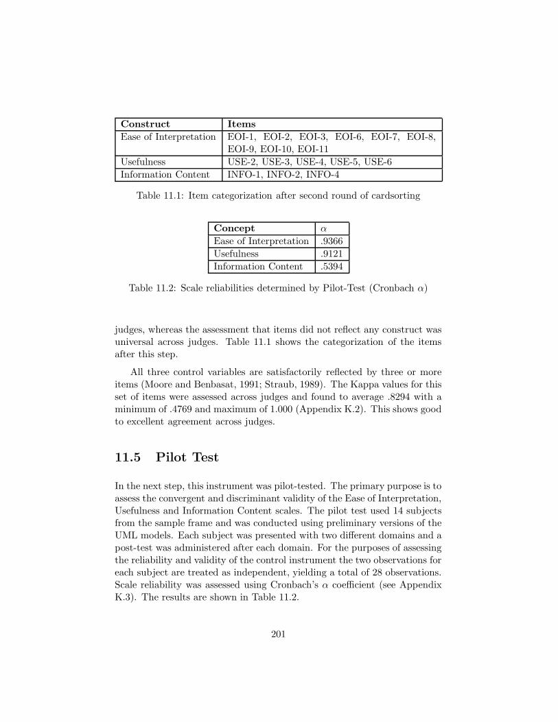
Construct Items
Ease of Interpretation EOI-1, EOI-2, EOI-3, EOI-6, EOI-7, EOI-8,EOI-9, EOI-10, EOI-11
Usefulness USE-2, USE-3, USE-4, USE-5, USE-6
Information Content INFO-1, INFO-2, INFO-4
Table 11.1: Item categorization after second round of cardsorting
Concept α
Ease of Interpretation .9366
Usefulness .9121
Information Content .5394
Table 11.2: Scale reliabilities determined by Pilot-Test (Cronbach α)
judges, whereas the assessment that items did not reflect any construct wasuniversal across judges. Table 11.1 shows the categorization of the itemsafter this step.
All three control variables are satisfactorily reflected by three or moreitems (Moore and Benbasat, 1991; Straub, 1989). The Kappa values for thisset of items were assessed across judges and found to average .8294 with aminimum of .4769 and maximum of 1.000 (Appendix K.2). This shows goodto excellent agreement across judges.
11.5 Pilot Test
In the next step, this instrument was pilot-tested. The primary purpose is toassess the convergent and discriminant validity of the Ease of Interpretation,Usefulness and Information Content scales. The pilot test used 14 subjectsfrom the sample frame and was conducted using preliminary versions of theUML models. Each subject was presented with two different domains and apost-test was administered after each domain. For the purposes of assessingthe reliability and validity of the control instrument the two observations foreach subject are treated as independent, yielding a total of 28 observations.Scale reliability was assessed using Cronbach’s α coefficient (see AppendixK.3). The results are shown in Table 11.2.
201

The reliabilities are excellent for the Ease of Interpretation (α = .9366)and Usefulness (α = .9121) constructs and adequate to good for the In-formation Content construct (α = .5394). The result for the InformationContent is likely caused by the fact that the last construct is measured ona three item scale, which is generally accepted as the lower bound for thenumber of items per construct5.
A confirmatory factor analysis (maximum likelihood extraction withvarimax rotation) was conducted to assess the convergent and discriminantvalidity of the scales (Appendix K.3). Due to the very small sample size,the samples of the two domains were combined to yield n = 28 observa-tions. Hence, the observations are not completely independent, even thoughsubjects responded to two different diagrams. For this reason, and the factthat even n = 28 observations is a small sample size, the following analysiscannot provide firm statistical inferences and are intended to be indicativeonly.
The rotated factor loadings are shown in Table 11.3. The variance ex-plained by all three factors is 0.687. A χ2 test of the number of factorsrequired showed a non-significant p-value of .518 for a test statistic of 86.81with 88 degrees of freedom. Following the procedure of Harman (1976), atwo-factor solution was found to have a p-value of .156 while the single-factorsolution had a p-value of .001. Statistically this would indicate a single fac-tor solution. However, Harman (1976) warns that the χ2 test yields too lowan estimate for the number of factors on small data sets. He also cautionsagainst the sole use of statistical arguments for the number of factors.
Table 11.3 shows clearly the ”usefulness” construct as the first factorwith good convergent validity (high loadings of items on that factor, > .65)and discriminant validity (low cross-loadings of items onto other factors,< .35). The other two constructs are problematic. Items ”EOI-7”, ”EOI-8”and ”EOI-10” form a clear and distinct factors, but items ”EOI-2”, EOI-3”, and ”EOI-6” cross-load heavily onto a third factor. Items ”EOI-1” and”EOI-9” load onto this third factor altogether. This would suggest thatEase of Interpretation is a multi-dimensional construct. Similarly, the itemsintended to reflect Information Content do not clearly form a single factor.
5The α value for the scale reliabilties using the responses for the first domain (the firstset of 14 observations) is .0360 while, when using the responses for the second domain(the second set of 14 observations, from the same subjects), it is .7286. This seems tosuggest differences in the two domains which affect subjects’ interpretation of the post-testquestionnaire items. This effect will be revisited when analyzing the final data.
202

Item Factor1 Factor2 Factor3
USE-2 0.747 0.244 0.142
USE-3 0.634 0.236 0.221
USE-4 0.813 0.164 0.211
USE-5 0.872 0.323
USE-6 0.806 0.281
EOI-7 0.357 0.837 0.130
EOI-8 0.382 0.780 0.403
EOI-10 0.432 0.749 0.397
EOI-3 0.334 0.630 0.649
EOI-2 0.244 0.622 0.690
EOI-6 0.529 0.462
EOI-11 0.481 0.382 0.264
EOI-1 0.406 0.244 0.678
EOI-9 0.220 0.233 0.628
INFO-1 0.505 0.530
INFO-2 0.328 0.720
INFO-4 0.129 -0.598
Table 11.3: Rotated factor loadings, pilot-test (values < .1 omitted)
However, due to the very small sample size, no firm statistical inferencescan be drawn. A final confirmatory factor analysis is performed on the largerdata set from the main study (see Sec. 11.8).
11.6 Subjects
The target population for this study is the set of business analysts partici-pating in the analysis stage of an IS project. These are distinct from systemanalysts in that they attempt to understand the business, not the IS. Typ-ically business analysts will have knowledge both of the business and theinformation systems aspect, although the business knowledge is not usuallyas deep as that of end users nor is the IS knowledge as deep as that of systemanalysts or system designers.
The sample frame for this study comprises undergraduate students intheir fourth year. The subjects were drawn from three groups of students,
203

forming three groups of subjects. This is controlled for by including thisvariable (”Group”) as a factor in the following analysis. One group of sub-jects has been drawn from a course in system analysis offered at the businessschool (factor level ”3”) while the others have been drawn from two sectionsof a system analysis course offered at the department of computer science.The latter two groups were enrolled in the spring section (factor level ”C”)and the summer section (factor level ”C2”) of this course. Both sectionswere taught by the same instructor and subjects from both sections partic-ipated in the study after the same amount of material had been covered ineither section.
All subjects had been exposed to the UML syntax through the systemsanalysis course materials and lectures. Student’s knowledge of UML andexperience in applying UML are two control variables in the following anal-ysis (”UML.TTL”, ”UML.A”). Student’s participation in the study wasvoluntary and entirely anonymous. Students did not receive course creditfor participation nor was credit withheld if students chose not to participate.The rationale for the study, theory and findings were made available to stu-dents after participating in the study. Subjects performed the experimentaltask in small groups of 5 to 6 students each, located in a small conferenceroom to reduce any distractions.
11.7 Design and Procedure
The experimental design included a within-subjects factor as it was feltthat the number of subjects that could be gained would not be very large.The factor ”Domain” with the levels ”CR” (car rental) and ”OP” (orderprocessing) was chosen as the within-subjects factor. This ensures minimalcarry-over and learning effects, which would have been possible had thefactor ”Rules” (rule conformance of diagrams) been chosen as within-factor.
Subjects were randomly assigned to one of three diagram types differ-ing by rule conformance (factor ”Rules” with levels ”N”, ”R”, and ”R2”).Each subject was given a questionnaire which included two diagrams andassociated comprehension and problem solving questions. The two diagramsdepicted the two domains (”Domain”) and the order of the diagrams wasvaried randomly between subjects to control for and exclude potential biasesfrom carry-over or learning effects. Subjects were asked to record the currenttime on various pages on the questionnaire. A wall clock was provided for
204
this purpose. Subjects were instructed not to revisit sections of the ques-tionnaire once they were completed. For each domain, the questionnaireincluded post-test questions measuring the control variables pertaining toeach diagram or domain. At the end of the questionnaire were the questionsmeasuring UML knowledge.
11.8 Results
Once data was collected, the scale reliabilities for the control variables werechecked again (Sec. 11.8.1) and the inter-rater reliability for the coding ofthe problem solving responses was assessed (Sec. 11.8.2). Then, a confir-matory factor analysis was conducted on the items for the control variables(Sec. 11.8.3). Finally, an ANCOVA procedure and a Linear Mixed EffectsModel (LME) was used to test the hypotheses (Sec. 11.8.4).
11.8.1 Scale Reliabilities
The scale reliabilities for the control variables Ease of Interpretation, Useful-ness, and Information Content were assessed using Cronbach’s α measure.Table 11.4 shows the values for the α coefficient, for n = 53 responses foreach domain. The first columns shows the values for the Car-Rental domain,the second column shows the values for the Order-Processing domain. Thisanalysis confirms excellent scale reliabilities for the Ease of Interpretationand Usefulness measures with α measures greater than .9, while the Informa-tion Content measures still show adequate to good reliabilities (alpha ≈ .65).This confirms the reliabilities assessed by the pilot-test (Sec. 11.5). Again,the lower result for the Information Content is likely a result of it being a3-item scale. With this full data set, the values for both domains are verysimilar. Hence, the differences between the two domains exhibited in thepilot test (Sec. 11.5) are likely a consequence of small sample size.
11.8.2 Interrater Reliabilities
The problem solving questions measuring the dependent variable (see Ap-pendix I) were open ended questions; subjects were asked to provide as manyanswers as they could think of. Therefore, no a-priori list of correct answerswas available against which to check the given answers. Two graduate stu-
205

Domain CR OP
Ease of Interpretation .9456 .9234
Usefulness .9176 .9243
Information Content .6297 .6897
Table 11.4: Scale reliabilities determined by Pilot-Test (Cronbach α)
dents with knowledge of the two domains were asked to rate the answers ascorrect or incorrect and to assess the total number of correct answers foreach question for each subject.
Initially, the two raters each received 15 completed questionnaires andwere asked to compile a list of correct answers. These lists were exchangedbetween the two raters who then combined their lists of correct answers.They each revisited the completed questionnaires they had rated to reflectany differences in assessment due to the combination of correct answer sets.They then independently rated the remainder of the questionnaires.
The final inter-rater agreement over all subjects was assessed using Co-hen’s Kappa (Appendix K.4). The agreement was computed for the numberof correct answers that each rater assessed for each problem solving question(typically ranging from 0 to 5)6. The average Kappa value for 0.9138 witha minimum of 0.7872 and a maximum of 1.000 showing excellent agreementbetween the two raters (Nyerges et al. (1998)). For further analysis, theaverage of the two raters’ scores was used (variable ”Prob”).
11.8.3 Convergent and Discriminant Validity
Convergent and discriminant validity was assessed using confirmatory factoranalysis (maximum likelihood extraction with varimax orthogonal rotation)by computing a 3-factor solution. The rotated factor loadings for each do-main are shown in tables 11.5 and 11.6.
For the car rental domain, the variance explained by three factors is .686.The table clearly shows the Usefulness construct as a single factor with verylittle cross-loading of items onto other factors. However, neither the Ease
6A more exact method would rate the assessment of both raters for each answer given,instead of the number of correct answers. While it is possible that by rating the numberof correct answers disagreements between raters could cancel out, the sharing of lists ofcorrect answers ensures adequate agreement.
206

Item Factor1 Factor2 Factor3
CR-EOI-1 0.792 0.213 0.424
CR-EOI-2 0.755 0.279 0.488
CR-EOI-3 0.767 0.174 0.533
CR-EOI-6 0.680 0.101
CR-EOI-7 0.490 0.206 0.765
CR-EOI-8 0.411 0.199 0.692
CR-EOI-9 0.662 0.168
CR-EOI-10 0.632 0.306 0.575
CR-EOI-11 0.613 0.176 0.372
CR-USE-3 0.343 0.796 0.183
CR-USE-4 0.355 0.810
CR-USE-5 0.121 0.726 0.433
CR-USE-6 0.350 0.795 0.108
CR-USE-2 0.315 0.563 0.586
CR-INFO-2 0.168 0.605 0.657
CR-INFO-1 0.360 0.316 0.201
CR-INFO-4 0.164 0.395
Table 11.5: Rotated factor loadings, car rental domain (values < .1 omitted)
of Interpretation nor the Information Content factor is clearly defined. Theitems intended to reflect Ease of Interpretation appear to express two factors,with items ”CR-EOI-7” and ”CR-EOI-8” heavily cross-loading. The itemsintended to reflect Information Content (”CR-INFO-1”, ”CR-INFO-2” and”CR-INFO-4”) do not appear to show any coherent factor structure.
A very similar result is obtained for the order processing domain. Here,the Ease of Information items again load heavily and even more clearlyon two distinct factors (”OP-EOI-7”, ”OP-EOI-8”, ”OP-EOI-10”). TheUsefulness items clearly load on a single factor, again with very little cross-loading, while the Information Content items do not reflect any clear factorstructure.
Generally, the Ease of Interpretation and Usefulness constructs are ad-equately represented by the developed item set. The main problem is thatthe Information Content measure does not show convergent validity. TheEase of Interpretation construct also exhibits item loadings that are indica-tive of two sub-factors, with items EOI-1, EOI-2, EOI-3, EOI-6, EOI-9, and
207

Factor1 Factor2 Factor3
OP-USE-2 0.720 0.206 0.215
OP-USE-3 0.784 0.335 0.295
OP-USE-4 0.764 0.155
OP-USE-5 0.876 0.185 0.201
OP-USE-6 0.894 0.174
OP-INFO-2 0.587 0.336 0.245
OP-INFO-1 0.411 0.266 0.254
OP-INFO-4 0.382
OP-EOI-1 0.154 0.822 0.299
OP-EOI-2 0.258 0.839 0.286
OP-EOI-3 0.208 0.772 0.381
OP-EOI-6 0.547 0.173
OP-EOI-9 0.111 0.600
OP-EOI-11 0.346 0.522 0.389
OP-EOI-7 0.256 0.384 0.885
OP-EOI-8 0.195 0.448 0.653
OP-EOI-10 0.291 0.443 0.657
Table 11.6: Rotated factor loadings, order processing domain (values < .1omitted)
208

EOI-11 forming one factor while items EOI-7, EOI-8, and EOI-10 forminganother factor. Referring to the items making up this factor, it appears pos-sible that there is a difference between the ease of understanding a diagramand the ease of interpreting a diagram.
However, what is of primary interest for this study is to control forusefulness (Sec. 11.9): While additional information may or may not bepresent, it is not relevant if not found useful for the task. Bartlett factorscores are computed for further use of these factors as covariates for the linearmodels used in the next section (variables ”Interpretation”, ”Usefulness”,and ”Information”).
11.8.4 Hypothesis Testing
Different statistical techniques, such as ANOVA or regresseion analysis, canbe brought to bear on the model shown in Fig. 11.1. Due to the variables ruleconformance and group being 3-level factors, a t-test for difference of meanscannot be used. While a regression analysis would allow the estimationand significance tests of the continuous control variables, such as ease ofinterpretation and usefulness, the aim of this study is to identify possibledifferences in problem solving behaviour due to the different levels of ruleconformance. All other variables are considered control variables, and arenot of primary interest in this study. Due to this reason, an analysis ofvariance with continuous co-variates is appropriate. As the experimentalmodel includes a within-subject component, a repeated measures, mixed-effects ANCOVA is appropriate (Shavelson, 1996). The null-hypothesis ofthis study is that the means of problem solving behaviour across all threelevels of rule conformance are identical. Rejection of this hypothesis atthe level of significance generally accepted (.05) then indicates that ruleconformance does indeed lead to differences in problem solving capabilities.Control variables are included in order to explain variance in the data, buttheir parameters are not of interest, so that a regression analysis is notrequired. Further, as the means in Tab. 11.7 clearly show the differences,a Tukey (1977) or Scheffe (1959) post-hoc test for specific means is notnecessary.
While the chosen ANCOVA approach is suitable also for within-subjectexperimental designs as in the present case, the more recent linear mixedeffects (LME) approach (Pinheiro and Bates, 2000) can complement thistechnique. In contrast to ANOVA and ANCOVA techniques, LME does
209

Sub
ject
2118493924322847203350219817304153294272622511623153148114038354361434273437461236459255213151044
1 2 3 4
CR3
OP3
2118493924322847203350219817304153294272622511623153148114038354361434273437461236459255213151044
CRC
OPC
2118493924322847203350219817304153294272622511623153148114038354361434273437461236459255213151044
CRC2
OPC2
1 2 3 4N R R2
Figure 11.4: Scatterplots by group and domain
210

not maximize the explained variance of the model, but instead computesa maximum likelihood estimate of the model parameters, i.e. the groupmeans of the factors and regression coefficients fo the covariates. The LMEapproach provides ultimately the same information as the ANCOVA, butuses a different statistical method. Its use in this research serves to provideadditional validation of the results, a multi-method approach to data analyisintended to increase the robustness of the statistical results.
Further, for models involving a larger number of fixed and random ef-fects, as is the case in the present model, the linear mixed effects modellingtechnique allows more expressive modelling. The advantage of LME mod-elling is the ability to expressly account for random effects such as experi-mental subjects in the present within-subjects design, and to model nestedstructures of such blocks. LME can also help deal with asphericity of data,non-uniformity of errors across factor level, as potential sources of aspheric-ity can be included as random effects. The main text of this thesis providesthe standard ANCOVA approach while the LME approach can be found inAppendix J.3. Post-hoc validation of model assumptions for both ANCOVAand LME can be found in Appendix. J.2.
211

Rule Conformance Domain Subject Group
No
Rules
(N)
Rules
(R)
Partial
Rules
(R2)
Results Car
Rental
(CR)
Order
Proc.
(OP)
Results Business
Stu-
dents
(3)
Comp.
Science
Stu-
dents 1
(C)
Comp.
Science
Stu-
dents 2
(C2)
Results
Means(SD)
Means(SD)
Means(SD)
F(sig.)
Means(SD)
Means(SD)
F(sig.)
Means(SD)
Means(SD)
Means(SD)
F(sig.)
n=16 n=17 n=20 n=53 n=53 n=14 n=26 n=13
Problem
Solving
Perfor-
mance
1.4558(0.6720)
1.8437(1.003)
1.3996(0.6439)
4.0583(.021)
*
1.6019(0.8648)
1.5162(0.7388)
0.4422(.508)
1.9250(0.9406)
1.3313(0.5736)
1.6203(0.9002)
6.687(.002)
**
Table 11.7: Main effects of rule conformance, domain and subject group on problem solving performance, measuredin avg. number of correct answers per question
212

Before any statistical methods are applied, the data is examined visuallyand summarized in Table 11.7. Note that Ease of Interpretation, Usefulnessand Information Content are derived factor scores. These are by definitionzero-centered. Since factor scores were computed independently for eachdomain, there is no difference in the mean of these variables between thetwo domains.
Fig. 11.4 shows all data points plotted against subjects with indicationsof the rule conformance of the diagram (”N”, ”R”, ”R2”). The observa-tions are grouped by domain and subject group. No general tendencies orabnormalities can be visually identified.
An initial plot of the data shows the main effects of and interactioneffects between the major factors of the model. Fig. 11.5 shows box andwhisker plots (Tukey, 1977) of the following main effects. In the top dia-gram, it shows the main effect of rule conformance of the diagram (”Rules”)on problem solving performance; in the center diagram it shows the maineffect of the domain (”CR” = car rental, ”OP” = order processing) on prob-lem solving performance; in the bottom diagram it shows the main effect ofthe group of subjects (”3” = Business undergraduates, ”C”, ”C2” = firstand second group of computer science students) on problem solving perfor-mance. The domain does not appear to have an effect. Fig. 11.6 shows theinteraction effect of rule conformance (”Rules”) and the domain on problemsolving performance, while Fig. 11.7 shows the diagram and group interac-tions.
These plots suggest that the domain may not be relevant in the sta-tistical model as the two domains follow the same pattern with respect toproblem solving performance by rule conformance. The difference in prob-lem solving performance between the two domains is very small, comparedto the effect size of rule conformance. However, the second interaction plot(Fig. 11.7) shows that the first group of computer science subjects did notfollow the general pattern of both the business students and the secondgroup of computer science students. That pattern indicates an increase inproblem solving performance for the diagram which conforms to all rules,while the problem solving performance for the two other types of diagramappears lower.
These visually suggested effects are analyzed statistically by the AN-COVA procedure and Linear Mixed Effects (LME) modelling7. The fol-
7The statistical analysis is done using the R statistics package with the procedure shown
213

N R R2
12
34
CR OP
12
34
3 C C2
12
34
Figure 11.5: Box plots showing main effects of Rules (top), Domain (middle)and Group (bottom) on problem solving performance.
214

1.4
1.5
1.6
1.7
1.8
1.9
Rules
mea
n of
Pro
b
N R R2
Domain
CROP
Figure 11.6: Interaction effects of Rules and Domain on problem solvingperformance
215

1.2
1.4
1.6
1.8
2.0
2.2
2.4
2.6
Rules
mea
n of
Pro
b
N R R2
Group
3CC2
Figure 11.7: Interaction effects of Rules and Group on problem solvingperformance
216

lowing paragraphs show the ANCOVA analysis. The LME analysis can befound in Appendix J.2 and confirms the ANCOVA results.
ANCOVA The ANCOVA model is set up to include the factors ”Rules”,”Group” and ”Domain” as well as their first order interactions and furtherincludes the following control variables as continuous covariates without in-teraction effects:
• UML.TTL: Total score on the UML assessment questions
• UML.A: Self-assessed UML knowledge (7-Point Likert)
• SelfAsssess : Self-assessed domain knowledge (7-point Likert)
• Time: Time taken for problem solving
• Comp: Average comprehension score
• Interpretation: Ease of interpretation factor scores
• Usefulness: Usefulness factor scores
• Information: Information content factor scores
Table 11.7 shows the results of the ANOVA for the main effects of ”Rules”,”Group” and ”Domain”. There is a statistically significant difference in themeans between different levels of rule conformance (p = .21) confirming thevisual identification of the effect. The mean for the fully rule conformingdiagrams was 1.8437 compared to 1.4558 and 1.3996 for the non-conformingand partially conforming diagram. This indicates a statistically significantincrease in problem solving performance. The domain did not have a sta-tistically significant effect, with means of 1.60 and 1.51 for the two domains(p = .51). There was a main effect of group on problem solving performance(p=.002).
The full results below also indicate a highly significant interaction ef-fect of ”Rules” and ”Group” (p=.002), which confirms the effect observedvisually in Fig. 11.7. This will be discussed further below.
Error: Subject
in Appendix K.7.
217

Df Sum Sq Mean Sq
Rules 1 1.3804 1.3804
Error: Within
Df Sum Sq Mean Sq F value Pr(>F)
Rules 2 3.574 1.787 4.0583 0.020819 *
Domain 1 0.195 0.195 0.4422 0.507916
Group 2 5.889 2.944 6.6868 0.002030 **
UML.TTL 1 5.002 5.002 11.3609 0.001140 **
UML.A 1 0.006 0.006 0.0145 0.904564
SelfAssess 1 1.040 1.040 2.3624 0.128095
Time 1 1.035 1.035 2.3507 0.129029
Comp 1 1.215 1.215 2.7591 0.100473
Interpretation 1 0.021 0.021 0.0485 0.826308
Usefulness 1 0.352 0.352 0.8000 0.373691
Information 1 1.054 1.054 2.3934 0.125655
Rules:Domain 2 0.355 0.178 0.4032 0.669475
Rules:Group 4 8.157 2.039 4.6314 0.002004 **
Domain:Group 2 1.646 0.823 1.8692 0.160683
Residuals 83 36.546 0.440
---
Signif. codes: 0 *** 0.001 ** 0.01 * 0.05 . 0.1 1
The goodness of fit of the model is assessed as the ratio of explainedversus total variance. This ratio is R2 = .4582 which suggests that theexplanatory power of the model is adequate8. The data also shows that anumber of covariates do not have any explanatory power (low Sum Sq) andare not statistically significant.
The estimated improvement in problem solving performance for the ruleconforming diagrams is 0.388 (average correct answers per question). Thisrepresents a 26% increase in problem solving performance. The performancefor the similar diagrams violating only one rule decreased by about 0.056(average correct answers per question) but this effect is not statisticallysignificant. While the effect of total UML knowledge (UML.TTL) is sta-tistically significant, the small magnitude of the parameter (.089) makes itdoubtful that it is practically relevant.
8R
2 ranges from 0 to 1. An R2
> .7 is considered excellent.
218

A further, extended, analysis using ANCOVA techniques and LinearMixed Effects Modelling can be found in Appendix J. A more parsimoniousmodel was derived using step-wise inclusion of variables (Appendix J.1. TheLME analysis is shown in Appendix J.2 and confirms the ANCOVA re-sults in this chapter. A linear mixed effects allows more explicit modellingincluding fixed and random factors, such as occur in this within-subjectsdesign. Model assumptions of ANOVA and the LME model are tested inAppendix J.3 and found to hold for the data.
Equivalence of Diagrams One of the main assumptions is that the mod-els must be informationally equivalent with respect to information relevantto the task. Otherwise, the additional information could lead to improvedproblem solving performance. This assumption is assessed by analyzing theeffect of the different model types on the factors Information Content, Use-fulness and Ease of Interpretation. This is done using an ANOVA procedureincluding ”Domain”, ”Group” and ”Rules” together with second order in-teractions as independent variables (Appendix K.8). Detailled results areshown in Appendix J.4.
The results shows that there appears to be an effect of the subject groupon the perceived Information Content. However, this is uncertain due tothe measurement difficulties identified above. In any case, this effect onInformation Content does not appear to have an effect of Usefulness forproblem solving. In fact, none of the three examined factors had any effecton Usefulness. There was a significant effect of rule conformance of Ease ofInterpretation. The Ease of Interpretation for ”R” diagrams (µ = −.4571,σ = 1.103) was significantly less than that for ”N” (µ = .3111, σ = 1.008) or”R2” (µ = .1400, σ = .9517) diagrams. Diagrams conforming to ontologicalsemantics and rules are harder to interpret. However, ease of interpretationdoes not have a significant effect on problem sovling performance. This rulesout an interpretation of Ease of Interpretation as a mediator variable.
In conclusion, the results of the present analysis justify the assumptionof equivalence of the diagrams for the purposes of the problem solving task.
11.9 Discussion
Overall, the results confirm the hypothesis and underline the benefits ofthe ontologically derived modelling rules. Both the ANCOVA and LME
219

analyses identified the same significant influence variables, which are highlysignificant in the ANCOVA analysis and approached significance in the LMEanalysis. The detected effect sizes are not only statistically significant butlarge enough to be practically significant. The effect of modelling withontological rules leads to approximately a 26% increase in problem solvingperformance.
Another important aspect indicated by the results is the lack of anysignificant difference between the performance on diagrams that completelylack ontological rules and diagrams that follow all but a few specific suchrules. While this effect was only shown for the specific set of rules vio-lated in condition R2 in this study (violating the representation of mutualproperties by association class attributes), it can possibly point towards in-dications that the benefit derived from rule conformance may not be a linearphenomenon, i.e. that the benefit may only be realizable by a fully confor-mant model. At the very least, this finding indicates that there may existcertain threshold levels of rule conformance for certain rules or sets of rules.In terms of the underlying cognitive network theory, this implies that theentire model may have to match the mental network in order to be properlyintegrated.
It further appears that UML knowledge, as assessed by the compre-hensive post-test questionnaire (”UML.TTL”) also plays a partial role inexplaining the derived benefits, although the estimated effect size (≈ .09)does not appear to be practically significant. The self-assessed UML knowl-edge (”UML.A”) did not appear to have any impact, which suggests that itdiffers significantly from the objectively measured UML knowledge.
When examining possible differences in the Ease of Interpretation, Use-fulness of the diagrams or the Information Content, only an effect on theEase of Interpretation could be found. It appears that diagrams conformingto rules are easier to interpret than diagrams that do not conform to any ofthe rules. However, there is also a difference between the fully conformantdiagram (”R”) and the one which violates a few rules only (”R2”). This dif-ference may stem from the lack of the ternary association symbol (diamondshape symbol). This reduction in the number of UML constructs used in themodel may have influenced the Ease of Interpretation assessment. However,the original diagrams (”N”) did not make use of this construct either, sothis explanation does not tell the whole story.
Chapters 9 and 10 showed that following the proposed rules and ad-hering to the proposed ontological semantics tends to add information to
220

the model. It is possible, and indeed the analysis has shown, that this in-formation makes the resulting models more difficult to interpret. However,this increased difficulty of interpretation has no impact on the domain un-derstanding. Any claim that the rules should not be followed as they leadto more difficult to interpret models, fails to take into account the purposeof the model, as ultimately it must convey domain understanding, not nec-essarily be easy to interpret. Hence, the empirical results of this chapterconfirm the argument made in Chaps. 9 and 10 that an initial diagramshould be built which fully conforms to the proposed semantics. Only in asecond, explicit, transformation step, may information be removed or rulesviolated to make the model e.g. better suited for database implementation.
The most interesting phenomenon is the interaction of the rule confor-mance of the diagrams with the group that subjects are drawn from. Nooutliers are present in the data which could account for this, suggestingthat a deeper explanation is needed. One could have expected differencesbetween the computer science subjects and business student subjects, be-cause of their different educational history. Instead differences arose betweentwo groups of computer science student subjects. This is all the more sur-prising as they had received the same instructions in UML and were taughtby the same instructor. Subjects were recruited after the same stage intheir UML instruction. Possible explanations are motivational. The secondset of subjects were taken from a summer semester course and may havebeen more motivated to perform in the study. As the university that sub-jects were drawn from does not generally offer summer courses, it is possiblethat these were highly motivated students making use of the offering of thatcourse.
A test for an influence of subject group on time spent on the task sup-ports this explanation (Appendix K.8). Subjects in group ”C” spent about2.5 minutes less on the problems than the average. However, this did nottranslate into a significant effect of time on problem solving performance.
The effect of subject group on UML knowledge was also examined insearch for an explanation. Both computer science student subject groupsactually had significantly lower scores on the UML knowledge instrumentthan the group of business students. However, there was no significant sta-tistical difference between the two, ruling out differences in UML knowledgeas a possible explanation.
221

11.10 Potential Limitations
Generally, potential limitations of an empirical study can arise out of threatsto internal, external or statistical validity. Internal validity may be compro-mised due to factors outside the model influencing the dependent variable.In order to minimize the potential for this, subjects were randomly assignedto a domain. While the study attempted to control for a number of poten-tial factors that could influence the problem solving outcome, the model fit,which is only average, indicates that factors other than those examined heremay play a role.
Another issue is the statistical power of the experiment. (Howell, 1997)suggests that in order to detect a medium effect size at the 0.05 significancelevel requires about 30 subjects. The size of the effect in our study waspractically significant and with 53 subjects clearly detectable, the ANCOVAmodel was clearly significant and the same factors approached significancein the LME model.
A third potential issue is the measurement instrument itself. The in-strument is derived from previous work (Gemino, 1999; Bodart et al., 2001)and has been re-validated. One potential problem may stem from the factthat the convergent and discriminant validity for the Information Contentcontrol variable was marginal. However, the main confounding effect shouldnot have come from different information content between diagrams butfrom differences in the perceived usefulness of the various diagrams. Theusefulness scale on the other hand was derived from Moore and Benbasat(1991) and re-validation showed excellent validity.
External validity may be threatened by a potential lack of generaliz-ability from subjects to target population. As outlined above, the targetpopulation profile roughly matches that of the experimental subjects, butany generalizations beyond this target population should only be made withgreat care. The results also clearly show differences in the way that differentgroups respond to the different diagrams. This is all the more difficult toexplain as the difference was not between computer science students andbusiness students but between the two groups of computer science students.Future research must aim to find a more homogeneous sample set whichis also a better representation of the target population. Subjects shouldbe participants in actual IS development projects in actual organizations.However, the resource demand required for such a study may make thisinfeasible.
222

Chapter 12
Contributions
This thesis has assigned ontological real-world semantics to UML. While itis not the first work to assign semantics to UML, it is the first to do so not bytranslating UML to other, more formal languages. Instead, we have mappedUML elements to elements of the real world, such as found in business andorganizational domains. For example, things have been mapped to objectsand mutual properties to attributes of association classes. Conversely, UML-events have been mapped to state transitions, etc.
This mapping can serve as the first step towards a commonly acceptedmeaning for UML constructs in business and organizational modelling andcan contribute to a better understanding of conceptual models. As UML isan evolving language, this result is relevant from a theoretical perspectiveas it can guide that evolution of the language. For the practitioner, thiscreates a common language that business analysts can employ and withwhich IS and software designers are immediately familiar, helping to bridgethe often wide gulf between the two. This enables all participants of an ISdevelopment project to realize the full potential of conceptual models as acommunication medium in reasoning about the problem domain.
Furthermore, this is not the first study to examine UML from the per-spective of the BWW-ontology. However, it is the first study to do thisconstructively. Previous studies such as (Opdahl and Henderson-Sellers,2002; Dussart et al., 2002) pointed out weaknesses by examining the map-ping. This research goes beyond pointing out the ontological defects andinstead suggests rules and guidelines for the modeller and analyst which al-leviate these problems and enable the use of UML for conceptual modelling
223
of real-world domains. These rules not only show how certain aspects of thereal-world domain are to be modelled in UML, but also guide the modellerto seek out and include additional information in the model. This lattereffect is demonstrated by the two examples in Chap. 9 and the case studyin Chap. 10.
For the academic community, this study shows a way to extend the ideaof ontological evaluation in a more constructive way. It provides solutionsto possible ontological defects found during an evaluation. For example, onecould simply argue that operations and methods are ontologically redundant.Yet, the fact that they play a prominent role in object-oriented techniquesmakes it clear that a consistent way of modelling them must be found.
For the practitioner, the rules and guidelines developed are immediatelyaccessible and can be put to practice. They are operationalizable and specificto enable their use in real modelling and analysis projects. The analysis ofUML and derivation of rules provides a practical and detailed guide to usingUML in business analysis. This is underscored by the fact that the majorityof the developed rules can be expressed by the OCL language. This addssupport for the modeller by reducing any ambiguitites.
The formal aspect of this research answers the call for more meta-modelbased research (Rosemann and Green, 2002; Davies et al., 2003). Formaliza-tion serves to make the results unambiguous and operationalizable in CASEtools, so that automated support can be provided to the conceptual mod-eller. For the practitioner, such tool support may be useful in guiding themodelling process, rather than applying the rules to the final model andanalyzing the result after the process. The case study shows this processs.The initial model by the project team was not known to the researcher andan independent model was developed by following the guidelines providedby the rules. The size and complexity of the models also shows that CASEtool support is useful for such models.
Formalization and the use of OCL therefore furthers the practical rele-vance of this investigation. Potential CASE tools incorporating the proposedsemantics can be used to make this work easily accessible to practitionerswithout having to understand the underlying theory.
For the academic community, it shows the value and the usefulness oflanguage meta-model for ontological analysis and the assignment of seman-tics. Using the meta-model, our results are also able to better guide thedevelopment of the language syntax to encompass conceptual modelling re-
224

quirements. As the official UML standard includes formal constraints inOCL on meta-model elements, it is possible to add the proposed rules andconstraints to this set.
We have shown that the general process of our analysis is applicable toother languages. Rules relating e.g. to objects, attributes, and operationsare generalizable to other object-oriented langauges. Some of the more spe-cific rules and OCL expressions relate to idiosyncrasies of UML, e.g. thetreatment of signal receptions, actions, and events.
However, this clearly shows that other languages cannot only be evalu-ated ontologically, but that prescriptive modelling rules can be derived fromsuch an analysis. The methodology involving the transfer of ontological as-sumptions by virtue of a mapping is universally applicable to all languages.This study is a demonstration using UML as an example, as it is the mostwidely known object-oriented modelling language.
The two examples and the case study provided in this thesis serve todemonstrate the applicability of the results. The two examples show thedifference between models with and without ontological semantics. It showsthat UML models, even though labelled conceptual or analysis model bythe modeller, in fact do not truthfully represent the real world. They carryhidden, implicit assumptions, a prime example of this is the alternativeinterpretation of the order processing example in Chapter 9. The examplesand the case study show that models constructed with the proposed mappingand rules include more information than is needed for the IS design stage.It is this contextual information that can help understanding the domain.Also, both case study and the examples show that the level of detail isincreased by following the proposed rules. For example, the initial model bythe project team collapses a number of different attributes into a single class,while the independently developed model separates these and is thereforeable to indicate semantic relationships between them.
While the difference between analysis and design models is widely ac-knowledged in the research community, the case study can provide an exam-ple of the differences. It also shows that the process of conceptual modellingusing the provided semantics and rules does lead to useful outcomes. Thedeveloped models were of a size and complexity that is neither trivial norbeyond the capability of analysts to comprehend. It is a modelling processthat is practicable and usable in real projects. For the practitioner, the twoexamples and the case study can show how to ’think ontologically’. Theyshow a rigorous exclusion of any IS requirements or implementation concern
225

and focus strictly on real-world phenomena.
Finally, the experimental corroboration of the results cannot prove theproposed theoretical results to be true. It does however lend credibilityto the rules and semantics. The results support the hypothesis that ruleconformance leads to better domain understanding, a critical requirementin any IS project. Rule conformance had a statistically and practicallysignificant effect on problem solving behaviour, which is used as a measureof domain understanding.
The experimental study builds on earlier research by Gemino (1999) whodeveloped the instrument for assessing problem solving behaviour. Thisstudy successfully applied an adapted version of this instrument, therebyproviding further support for the usefulness of this instrument in IS research.This study also employed an instrument developed by and adapted fromMoore and Benbasat (1991). This instrument was revalidated to measurepotential influences such as Ease of Interpretation, Usefulness and Informa-tion Content of the models. It provides further support for the usefulnessof the original instrument.
To the practitioner, the experimental study complements the case studyto demonstrate not only the applicability but also the benefit of the pro-posed rules and semantics. It shows that the purpose of a conceptual model,i.e. furthering domain understanding, is indeed supported by the devel-oped theory. Problem solving performance using a rule conforming dia-gram was about 26% greater than problem solving performance using anon-conforming diagram.
Finally, this work serves as another pragmatic pillar of support for theBWW-ontology. As outlined in Chapter 2, as a fundamental philosophicalassumption, the choice of the BWW-ontology cannot be debated or criticizeda-priori and the end justifies the means. In this case, the end result doesindeed justify the choice of ontology, as the empirical results, both case studyand experimental study, indicate the usefulness and beneficial effects of thetheory developed on the basis of the chosen ontology.
226

Chapter 13
Future Extensions
Future extensions to this work are possible both in theoretical deductiveresearch as well as in the empirical research area. In a first step, the obtainedformal results can be operationalized in an actual CASE tool. This can serveto further demonstrate their immediate applicability. This CASE tool canserve as the object of empirical evaluation. It must be shown how such animplementation of our results can benefit the modeller during the processof analysis and conceptual modelling. The fact that most CASE tools arebased on language meta-models makes should facilitate the inclusion of theresults.
In Chapter 1 the case for the use of UML as exemplar language was mo-tivated by the fact that it would ease the transition from analysis to design.While the models developed according to the suggested rules and guidelinesare valid UML models and therefore tranferrable to software and program-ming code, model transformations may still be necessary for a variety ofreasons. Such transformations may for example increase the computationalefficiency of the resulting softare or adapt the software design to a specificunderlying database technology or programming language. While such im-plementation driven transformations are outside the scope of this thesis,they form an interesting area for further research.
While UML is the most widely accepted language for IS design, thereexist other IS design languages, object-oriented and otherwise. The method-ology of this thesis can be applied to the study of these languages as well.Besides providing real-world semantics to the target language, it would alsosupport the suitability of the proposed method. More constructive analysis
227
of languages such as ER diagrams, OML and ARIS are needed that not onlypoint out the incompatibilities with the BWW-ontology but show how thesecan be avoided.
The meta-model formalization in this work may be used as the startingpoint for a formal analysis. Techniques in the area of schema matching(Batini and Lenzerini, 1986; Rahm and Bernstein, 2001) appear useful toformally compare two meta-models. A meta-model of the BWW-ontologywas developed by Rosemann and Green (2002). A similar, more complete,model can be developed in UML, which makes it comparable to the UMLmeta-model. Schema based techniques from schema matching research canthen be applied. This provides a better basis than the mappings madein this thesis and in prior ontological evaluations. Those mappings, whileintuitive, are based on the researchers understanding and interpretation ofthe language and the ontology. In this research, we have attempted toprovide a comprehensive analysis to ensure that ’all the pieces fit’, which atleast to some degree alleviates this problem.
In the empirical research domain, the results of the experimental studypointed out possible future studies. The generally only adequate fit of themodels with the data shows that there may exist further variables that havenot been investigated. Future research might attempt to be explore thesevariables, their influence on problem solving behaviour and their relationshipto the semantics and rules proposed here.
The intriguing differences between groups of subjects also invites furtherstudy. A replication of this study with a different sample population canshed more light on this phenomenon. A study with practicing systems andbusiness analysts will be the most informative.
This thesis has examined UML and object-oriented design languagesfrom the perspective of their suitability for conceptual modelling. However,this must be put into the broader context of model and modelling quality.Frameworks by (Krogstie et al., 1995; Lindland et al., 1994), (Moody andShanks, 1994, 1998; Moody, 1998) and (Becker and Schutte, 1995, 1996;Rosemann and Schutte, 1997; Schutte, 1998; Schutte and Rotthowe, 1998;Rosemann, 1995; Schutte, 1999) provide some further criteria for model andmodelling quality. The adequacy of the language for the task (Schutte,1999) is but one of them. Likely the most important other criterion is thatof cost and effort of modelling. Cost and effort of modelling arises dueto learning and applying the modelling language and modelling rules, theconstruction of the model and the interpretation and comprehension of the
228

model. While the experimental study did not show any significant differencesin the time to interpret a model, other costs may stem from learning therules or applying the rules during model construction. These costs must beestimated by further research in order to enable a cost/benefit assessmentof the proposed rules and guidelines.
Future research may also want to examine the effect of the modellingrules on other quality dimensions such as pragmatic quality with respectto the interpreter, social quality with respect to the group of interpreters,flexibility, simplicity and completeness. Implementability is a quality crite-rion suggested by Moody and Shanks (1998) and partially addressed by theresults of the case study. The effects on comparability, clarity and relevanceas proposed by Becker and Schutte (1996) also remain to be empiricallyassessed.
229

Chapter 14
Conclusion
This thesis set out to provide a language for conceptual modelling. This lan-guage is intended to be usable both for conceptual and IS design, in order toalleviate potential problems when translating from one language to another.Since object-oriented languages are well accepted for IS design, this led tothe question of whether and how their use can be extended to include con-ceptual modelling of the business and organization. The Unified ModellingLanguage is used as a specific example of object-oriented languages.
This thesis investigated the question from an ontological perspective,first using theoretical deductive methods. This led to real-world semanticsand ontological rules for conceptual modelling. In a second step, empiricalmethods were applied to corroborate the applicability and usefulness of thetheoretical results. We have shown that the rules and semantics are appli-cable as well as beneficial to real-world modelling. They are generalizableto other object-oriented languages and enhance the domain understandingthat is imparted by conceptual models and remain valid starting points forIS design.
The important differences between the BWW-ontology and object-orientedlanguages lie in the areas of message passing, which is a concept related tosoftware design, and in the area of encapsulation, which is incompatible withthe ontological concept of mutual properties. Both of these language areashave been investigated and interpretation and representation mappings havebeen found to provide guidelines to the modeller even in these areas.
In conclusion, based on the results of this research, the answer to theresearch question posed in Chapter 1 is a resounding Yes, object-oriented
230

languages are usable for conceptual modelling and this research providesguidelines on how to use them. This research is an encouraging step inthe process of bridging the gulf between conceptual and design modelling.It provides a well-known language for the conceptual modeller and helpsbridge the gulf between the business analyst and the software designer.
231

Bibliography
Agarwal, R., Sinha, A. P., and Tanniru, M. (1996). Cognitive fit in require-ments modeling: A study of object and process methodologies. Journalof Management Information Systems, 13(2), 137–162.
Agarwal, R., De, P., and Sinha, A. P. (1999). Comprehending object andprocess models: An empirical study. IEEE Transactions of Software En-gineering, 25(4), 541–556.
Anderson, J. and Pirolli, P. (1984). Spread of activation. Journal of Exper-imental Psychology: Learning, Memory, and Cognition, 10, 791–798.
Anderson, J. R. (1995). Cognitive Psychology and its implications. W.H.Freeman and Company, New York, NY., fourth edition.
Angeles, P. (1981). Dictionary of Philosophy. Harper Perennial, New York,NY.
Arango, G. (1989). Domain analysis: From art form to engineering dis-cipline. In Proceedings of the fifth international workshop of softwarespecification and desing, pages 152–159.
Auramaki, E., Lehtinen, E., and Lyytinen, K. (1988). A speech-act-basedoffice modeling approach. ACM Transactions on Office Information Sys-tems, 6(2), 126–152.
Austin, J. (1962). How to do things with words. Harvard University Press,Cambridge, MA.
Barker, H., Grant, P., Jobling, C., and Townsend, P. (1993). The object-oriented paradigm: a means for revolutionising software development.Computing and Control Engineering Journal, pages 10–14.
232

Baron, J. and Li, Y. (2001). Notes on the use of R for psychology experimentsand questionnaires.
Batini, C. and Lenzerini, M. (1986). A comparativve analysis of method-ologies for database schema integration. ACM Computer Surveys, 18(4).
Batra, D., Hoffer, J. A., and Bostrom, R. P. (1990). Comparing represen-tations with relational and EER models. Communications of the ACM,33(2), 126–139.
Becker, J. and Schutte, R. (1995). Grundsatze ordnungsmaßiger Model-lierung. Wirtschaftsinformatik, 5, 435–445.
Becker, J. and Schutte, R. (1996). Handelsinformationssysteme. VerlagModerne Industrie, Landsber/Germany.
Benbasat, I. (1989). Laboratory experiments in informatin systems studieswith a focus on individuals: A critical appraisal. In I. Benbasat, edi-tor, The Information Systems Research Challenge: Experimental ResearchMethods. Harvard Business School, Boston, MA.
Bezivin, J. and Muller, P. (1999). UML: The birth and rise of a standardmodeling notation. In The Unified Modeling Language UML’98: Beyondthe notation, First International Workshop, Mulhouse, France, June 1998.
Bodart, F. and Weber, R. (1996). Optional properties versus subtyping inconceptual modeling: A theory and empirical test. In Proceedings of theInternational Conference on Information Systems, Dec. 16-18, 1996, page450.
Bodart, F., Sim, M., Patel, A., and Weber, R. (2001). Should optionalproperties be used in conceptual modelling? A theory and three empiricaltests. Information Systems Research, 12(4).
Booch, G. (1994). Object Oriented Analysis and Design with Applications.Benjamin/Cummings, Redwood City, CA.
Breu, R., Hinkel, U., Hofmann, C., Klein, C., Paech, B., Rumpe, B., andThurner, V. (1997). Towards a formalization of the unfied modeling lan-guage. In M. Aksit and S. Matsuoka, editors, Proceedings of ECOOP’97- 11th European Conference on Object-Oriented Programming, Jyvaskyla,Finland, June 1997. Springer Verlag.
233

Breu, R., Grosu, R., Hofmann, C., Huber, F., Kruger, I., Rumpe, B.,Schmidt, M., and Schwerin, W. (1998a). Exemplary and complete ob-ject interaction descriptions. Computer Standards and Interfaces, 19,335–345.
Breu, R., Grosu, R., Huber, F., Rumpe, B., and Schwerin, W. (1998b).Systems, views and models of UML. In M. Schader and A. Korthaus, edi-tors, The Unified Modeling Language, Technical Aspects and Applications.Physica Verlag, Heiderberg.
Bruel, J.-M. and France, R. B. (1999). Transforming UML models to formalspecifications. In The Unified Modeling Language UML’98: Beyond thenotation, First International Workshop, Mulhouse, France, June 1998.
Bunge, M. A. (1977). Ontology I: The Furniture of the World, volume 3 ofTreatise On Basic Philosophy. D. Reidel Publishing Company, Dordrecht,Holland.
Bunge, M. A. (1979). Ontology II: A World of Systems, volume 4 of TreatiseOn Basic Philosophy. D. Reidel Publishing Company, Dordrecht, Holland.
Capretz, L. F. (2003). A brief history of the object-oriented approach. Soft-ware Engineering Notes, 28(2).
Chisholm, R. (1996). A Realistic Theory of Categories - An Essay on On-tology. Cambridge University Press, Cambridge.
Churchill, G. (1979). A paradigm for developing better measures of market-ing constructs. Journal of Marketing Research, 16, 64–73.
Coad, P. and Yourdon, E. (1990). Object-Oriented Analysis. Yourdon Press,Englewood Cliffs, NJ.
Cockroft, S. and Rowles, S. (2003). Ontological evaluation of health models:Some early findings. In Proceedings of the 7th Pacific Asia Conference onInformation Systems, 10-13 July, Adelaide, Australia.
Cohen, J. (1960). A coefficient of agreement for nominal scales. Educationaland Psychological Measurement, 20(1), 37–46.
Cohen, S. and Northrop, L. (1998). Object-oriented technology and domainanalysis. In P. Devanbu and J. Poulin, editors, Proceedings of the FifthInternational Conference on Software Reuse, pages 86–93.
234

Coleman, D., Arnold, P., Bodoff, S., Dollin, C., and Gilchrist, H. (1994).Object-Oriented Development: The Fusion Method. Prentice-Hall, Engel-wood Cliffs, NJ.
Collins, A. and Loftus, E. (1975). A spreading activation theory of semanticprocessing. Psychological Review, 82, 407–428.
Collins, A. and Quillian, M. (1969). Retrieval time from semantic memory.Journal of Verbal Learning and Verbal Behavior, 8, 240–248.
Collins, A. and Quillian, M. (1970). Facilitating retrieval from semanticmemory: The effect of repeating part of an inference. Acta Psychologica,33, 304–314.
Davies, I., Green, P., Milton, S., and Rosemann, M. (2003). Using metamodels for the comparison of ontologies. In Proceedings of the 15th Confer-ence on Advanced Information Systems Engineering, CAiSE 2003, Velden,Austria.
Davis (1989). Perceived usefulness, perceived ease of use, and user accep-tance of information technology. MIS Quarterly, 13, 319–340.
Dussart, A., Aubert, B. A., and Patry, M. (2002). An evaluation of inter-organizational workflow modeling formalisms. Working paper, Ecole desHaute Etudes Commercials Montreal.
Evans, A. and Clark, A. (1998). Foundations of the unified modeling lan-guage. In 2nd Northern Formal Methods Workhop, Ilkley, ElectronicWorkshops in Computing. Springer Verlag.
Evans, A. and Kent, S. (1999). Core meta-modelling semantics of UML: thepUML approach. In UML’99 The Unified Modeling Language - Beyondthe Standard: Second International Workshop, Fort Collins, CO, October28-30, 1999, pages 99–115.
Evans, A., Lano, K., France, R., and Rumpe, B. (1999a). Meta-modellingsemantics of UML. In H. Kilov, editor, Behavioural Specifications forBusinesses and Systems. Kluwer.
Evans, A., France, R., Lano, K., and Rumpe, B. (1999b). The UML as aformal modeling notation. In The Unified Modeling Language UML’98:Beyond the notation, First International Workshop, Mulhouse, France,June 1998.
235

Evans, A. S. (1998). Reasoning with UML class diagrams. In Workshop onIndustrial Strength Formal Methods. WIFT’98 Florida. IEEE Press.
Evermann, J. and Wand, Y. (2001a). An ontological examination of objectinteraction in conceptual modeling. In Proceedings of the Workshop onInformation Technologies and Systems WITS’01, New Orleans, December15-16, 2001.
Evermann, J. and Wand, Y. (2001b). Towards ontologically based semanticsfor UML constructs. In H. Kunii, S. Jajodia, and A. Solvberg, editors,Proceedings of the 20th International Conference on Conceptual Modeling,Yokohama, Japan, Nov. 27-30, 2001, ER 2001.
Fettke, P. and Loos, P. (2003). Ontological evaluation of reference modelsusing the Bunge-Wand-Weber model. In Proceedings of the 2003 AmericasConference on Information Systems, August 4-6, Tampa, FL.
Fil, W. G. (1999). Wither object orientation? What is object orientation,anyway? ACM SIGAPL APL Quote Quad, 30(2), 3–6.
Fowler, M. and Kendall, S. (2000). UML Distilled : A Brief guide to thestandard object oriented modelling language. Addison Wesley, Reading,MA.
Galfione, P., Galdiolo, A., Valreio, A., and Cardino, G. (2000). Exploitingenterprise knowledge through domain analysis and frameworks: An ex-perimental work. In A. Tjoa, R. Wagner, and A. Al-Zobaidie, editors,Proceedings of the 11th international Workshop on Database and ExpertSystems Applications, 2000, pages 813–817.
Gemino, A. (1999). Empirical Comparisons of Systems Analysis ModelingTechniques. Ph.D. thesis, University of British Columbia, Canada.
Gemino, A. and Wand, Y. (2001). Comparing object oriented with struc-tured analysis techniques in conceptual modeling. Draft Manuscript.
Gomaa, H. (1992). An object-oriented domain analysis and modelingmethod for software reuse. In V. Milutinovic, B. Shriver, J. Nunamaker,and R. Sprague, editors, Proceedings of the Twenty-Fifth Hawaii Interna-tional Conference of System Sciences, 1992, pages 46–52, Vol. 2.
Gopnik, A. (2001). Theories, language and culture. In M. Bowerman andS. Levinson, editors, Language Acquisition and Conceptual Development,pages 45–69. Cambridge University Press, New York, NY.
236

Green, P. and Rosemann, M. (2000). Ontological analysis of integratedprocess modelling. Information Systems, 25(2).
Gruninger, M. and Lee, J. (2002). Ontology applications and design. Com-munications of the ACM, 45(2), 39–41.
Guarino, N. and Welty, C. (2002). Evaluating ontological decisions withontoclean. Communications of the ACM, 45(2), 61–65.
Harel, D. (1988). On visual formalisms. Communications of the ACM, 31(5),514–530.
Harel, D. and Gery, E. (1996). Executable object modeling with statecharts.In Proceedings of ICSE-18, pages 246–256.
Harel, D. and Kupferman, O. (2000). On the behavioral inheritance ofstate-based objects. In Proceedings of the 34th international conferenceon Technology of Object-Oriented Languages, 2000. TOOLS 34, pages 83–94.
Harman, H. H. (1976). Modern Factor Analysis. The University of ChicagoPress, Chicago, IL, 3rd edition.
Hirsh-Pasek, K., Reeves, L. M., and Golinkoff, R. (1993). Words and mean-ing: From primitives to complex organization. In J. Gleason and N. Rat-ner, editors, Psycholinguistics, pages 133–197. Holt, Rinehart, &Winston,Orlando, FL.
Hoffer, J. A., George, J. F., and Valacich, J. S. (2002). Modern SystemsAnalysis and Design. Prentice Hall, Upper Saddle River, NJ.
Holsaple, C. W. and Joshi, K. (2002). A collaborative approach to ontologydesign. Communications of the ACM, 45(2), 42–47.
Howell, D. (1997). Statistical Methods for Psychology. Duxbury Press, Del-mont, CA.
Hufnagel, E. M. and Conca, C. (1994). User response data: The potentialfor errors and biases. Information Systems Research, 5(1), 48–73.
Ihaka, R. and Gentleman, R. (1996). R: A language for data analysis andgraphics. Journal of Computational and Graphical Statistics, 5(3), 299–314.
237

Jacobson, I. (1992). Object-Oriented Software Engineering: A Use CaseDriven Approach. Addison-Wesley, Wokingham.
Jayase, T., Ikeda, N., and Matsumoto, K. (2001). A three-view model fordeveloping object-oriented frameworks. In Q. Li, R. Riehle, G. Pour,and B. Meyer, editors, 39th international conference and exhibition ontechnology of object-oriented languages and systems, 2001. TOOLS 39,pages 108–119.
Johnson, R. A. (2002). Object-oriented systems development: A review ofempirical research. Communications of the Association for InformationSystems, 8, 65–81.
Kim, J. and Lerch, F. J. (1997). Why is programming (sometimes) so dif-ficult? Programming as scientific discovery in multiple problem spaces.Information Systems Research, 8(1), 25–50.
Kim, J., Hahn, J., and Hahn, H. (2000). How do we understand a systemwith (so) many diagrams? Cognitive integration processes in diagram-matic reasoning. Information Systems Research, 11(3), 284–303.
Kirstensen, B. B. and Osterbye, K. (1996). A conceptual perspective on thecomparison of object-oriented programming languages. ACM SIGPLANNotices, 31(2), 42–54.
Knapp, A. (1999). A formal semantics for UML interactions. In UML’99 TheUnified Modeling Language - Beyond the Standard: Second InternationalWorkshop, Fort Collins, CO, October 28-30, 1999, pages 116–130.
Korson, T. and McGregor, J. D. (1990). Understanding object-oriented: Aunifying paradigm. Communications of the ACM, 33(9), 40–60.
Krogstie, J., Lindland, O. I., and Sindre, G. (1995). Towards a deeperunderstanding of quality in requirements engineering. In Proceedings ofthe CAISE’95 Conference, pages 82–95.
Kuhn, T. (1996). The structure of scientific revolutions. The University ofChicago Press, Chicago, third edition.
Kung, C. and Solvberg, A. (1986). Activity modelling and behaviour mod-elling. In T. Olle, H. Sol, and A. Verrijn-Stuart, editors, InformationSystem Design Methodologies: Improving the Practrice. Addison-WesleyPublishing Co., Amsterdam.
238

Lakoff, G. (1987). Women, Fire, and Dangerious Things – What Categoriesreveal about the Mind. The University of Chicago Press, Chicagor, IL.
Lakos, C. and Lewis, G. (2000). Behaviour inheritance for object lifecy-cles. In Proceedings of the 33rd international conference on Technology ofObject-Oriented Languages, 2000. TOOLS 33, pages 262–273.
Lano, K. and Bicarregui, J. (1999). Semantics and transformations for UMLmodels. In The Unified Modeling Language UML’98: Beyond the notation,First International Workshop, Mulhouse, France, June 1998, pages 107–119.
Lano, K. and Evans, A. (1999). Rigorous development in UML. InETAPS’99, FASE workshop, Lecture Notes on Computer Science.Springer Verlag.
Larkin, J. H. and Simon, H. A. (1987). Why a diagram is (sometimes) worthten thousand words. Cognitive Science, 11, 65–99.
LeGrand, A. (1998). Specialization of object lifecycles. In C. Rolland andG. Grosz, editors, Proceedings of the Internationl Conference on ObjectOriented Information Systems, 9-11 September 1998, Paris., pages 259–275.
Lilius, J. and Paltor, I. (1999). Formalising UML state machines for modelchecking. In UML’99 The Unified Modeling Language - Beyond the Stan-dard: Second International Workshop, Fort Collins, CO, October 28-30,1999, pages 430–445.
Lim, K. H. and Benbasat, I. (2000). The effect of multimedia on perceivedequivocality and perceived usefulness of information systems. MIS Quar-terly, 24(3), 449–471.
Lindland, O. I., Sindre, G., and Solvberg, A. (1994). Understanding qualityin conceptual modeling. IEEE Software, 11(2), 42–49.
Mackworth, A. K. (1977). Consistency in networks of relations. ArtificialIntelligence, pages 99–118.
Mayer, R. E. (1989). Models for understanding. Review of EducationalResearch, 59(1), 43–64.
Meyer, B. (1996). The many faces of inheritance: A taxonomy of taxonomy.IEEE Computer, 29(5), 105–108.
239

Miller, L. (2002). Instructor’s Resource Manual for Modern Systems Anal-ysis and Design. Pearson Education, Upper Saddle River, NJ.
Milton, S. and Kazmierczak, E. (1999). Enriching the ontological founda-tions of modelling in information systems. In Proceedings of the Informa-tion Systems Foundation Workshop. Ontology, Semiotics and Practice,1999.
Moody, D. (1998). Metrics for evaluating the quality of entity relationshipmodels. In Proceedings of the ER’98 Conference, New York, NY. SpringerVerlag.
Moody, D. and Shanks, G. (1994). What makes a good data model? eva-lutating the quality of entity relationship models. In Proceedings of theER’94 Conference, New York, NY. Springer Verlag.
Moody, D. and Shanks, G. (1998). Improving the quality of entity relation-ship models - experience in research and practice. In Proceedings of theER’98 Conference, New York, NY. Springer Verlag.
Moore, G. C. and Benbasat, I. (1991). Development of an instrument tomeasure the perceptions of adopting an information technology innova-tion. Information Systems Research, 2(3), 192–222.
Morandin, E., Stellucci, G., and Baruchelli, F. (1998). A reuse-based soft-ware process based on domain analysis and OO framework. In Proceedingsof the 24th Euromicro Conference, pages 890–897, Vol. 2.
Morisio, M., Travassos, G., and Stark, M. (2000). Extending UML to sup-port domain analysis. In Proceedings of the Fifteenth IEEE InternationalConference on Automated Software Engineering, ASE, pages 321–324.
Mylopoulos, J. (1992). Conceptual modeling and telos. In P. Locuopoulosand R. Zicari, editors, Conceptual Modeling, Databases and Cases. JohnWiley & Sons, Inc, New York et. al.
Newell, A. and Simon, H. A. (1972). Human Problem Solving. Prentice Hall,Englewood Cliffs, NJ.
Norman, D. (1986). Cognitive engineering. In D. Norman and S. Draper,editors, User Centered Design: New Perspectives on Human ComputerInteraction. Lawrence Erlbaum Associates, Hillsdale, NJ.
240

Noy, N. F. and Hafner, C. D. (1997). The state of the art in ontology design:A survey and comparatie review. AI Magazine, 18(3), 53–74.
Nyerges, T., Moore, T., Montejano, R., and Compton, M. (1998). Devel-oping and using interaction coding systems for studying groupware use.Human-Computer Interaction, 13, 127–165.
OMG (2001). The Unified Modelling Language Specification. Version 1.4.OMG.
Opdahl, A. and Henderson-Sellers, B. (1999). Evaluating and im-proving OO modelling languages using the BWW-model. In Pro-ceedings of the Information Systems Foundation Workshop 1999.www.comp.mq.edu.au/isf99/Opdahl.htm.
Opdahl, A. and Henderson-Sellers, B. (2002). Ontological evaluation ofthe UML using the Bunge-Wand-Weber model. Software and SystemsModeling, 1(1), 43–67.
Opdahl, A. and Sindre, G. (1993). Concepts for real-world modelling. InProceedings of Conference on Advanced Information Systems EngineeringCAiSE’93, pages 309–327.
Opdahl, A., Henderson-Sellers, B., and Barbier, F. (1999). An ontologicalevaluation of the OML metamodel. In E. Falkenberg and K. Lyytinen, ed-itors, Information System Concepts: An Integrated Discipline Emerging.IFIP/Kluwer.
Opdahl, A. L. and Henderson-Sellers, B. (2001). Grounding the OML meta-model in ontology. The Journal of Systems and Software, 57(2), 119–143.
Overgaard, G. (1999). A formal approach to collaborations in the unifiedmodeling language. In UML’99 The Unified Modeling Language - Beyondthe Standard: Second International Workshop, Fort Collins, CO, October28-30, 1999, pages 99–115.
Overgaard, G. and Palmkvist, K. (1999). A formal approach to use cases andtheir relationships. In The Unified Modeling Language UML’98: Beyondthe notation, First International Workshop, Mulhouse, France, June 1998,pages 406–418.
Parsons, J. and Wand, Y. (1991). The object paradigm – two for the priceof one? In Proceedings of the Workshop on Information Technology andSystems WITS 1991, pages 308–319.
241

Parsons, J. and Wand, Y. (1997). Using objects for systems analysis. Com-munications of the ACM, 40(12), 104–110.
Philippow, I. and Riebisch, M. (2001). Systematic definition of reusable ar-chitectures. In Proceedings of the Eigth Annual IEEE International Con-ference and Workshop on the Engineering of Computer Based Systems,ECBS, pages 128–135.
Pinheiro, J. and Bates, D. (2000). Mixed-Effects Models in S and S-PLUS.Springer Verlag, New York, NY.
Quine, W. v. O. (1953). Two dogmas of empiricism. In From a Logical Pointof View. Harvard University Press, Cambridge, MA.
Rahm, E. and Bernstein, P. A. (2001). A survey of approaches to automaticschema matching. The VLDB Journal - The International Journal onVery Large Databases, 10(4), 334–350.
Rosemann, M. (1995). Beschreibung und Gestaltung der Produktion auf derBasis der Grundsatze Ordnungsmaßiger Modellierung. Working paper,University of Muenster, Germany.
Rosemann, M. and Green, P. (1999). Enhancing the process of ontologicalanalysis – the who cares dimension. In Proceedings of the InformationSystems Foundation Workshop. Ontology, Semiotics and Practice, 1999.
Rosemann, M. and Green, P. (2000). Developing a meta-model for theBunge-Wand-Weber (BWW) ontological constructs. Technical report, De-partment of Commerce, University of Queensland.
Rosemann, M. and Green, P. (2002). Developing a meta-model for theBunge-Wand-Weber ontological constructs. Information Systems, 27(2),75–91.
Rosemann, M. and Schutte, R. (1997). Grundsatze ordnungsmaßiger Ref-erenzmodellierung. Working paper, University of Muenster, Germany.
Rosemann, M. and zur Muhlen, M. (1998). Evaluation of workflow manage-ment systems – a meta-model approach. Australian Journal of Informa-tion Systems, 6(1), 103–116.
Rumbaugh, J. et al. (1991). Object Oriented Modeling and Design. PrenticeHall, Englewood Cliffs, NJ.
242

Scheer, A.-W. (1999). ARIS – Business Process Modeling. Springer Verlag,Berlin.
Scheffe, H. (1959). Analysis of Variance. Wiley, New York, NY.
Schrefl, M. and Stumptner, M. (2002). Behavior-consistent specializationof object life cycles. ACM Transactions of Software Engieneering andMethodology, 11(1), 92–148.
Schutte, R. (1998). Grundsatze ordnungsmaßiger Referenzmodellierung.Gabler Verlag, Wiesbaden, Germany. Also PhD Dissertation, Universityof Munster, Germany.
Schutte, R. (1999). Architectures for evaluating the quality of informationmodels - a meta and an object level comparison. In Proceedings of theER’99 Conference, New York, NY. Springer Verlag.
Schutte, R. and Rotthowe, T. (1998). The guidelines of modeling - anapproach to enhance the quality in information models. In Proceedings ofthe ER’98 Conference, pages 240–254.
Searle, J. (1969). Speech Acts. Cambridge University Press, Cambridge,UK.
Shavelson, Richard, J. (1996). Statistical Reasoning for the Behavioral Sci-ences. Allyn and Bacon, Needham Heights, MA, 3rd edition.
Sinha, A. P. and Vessey, I. (1992). Cognitive fit: An emprirical study of re-cursion and iteration. IEEE Transactions of Software Engineering, 18(5),368–379.
Smith, B. and Welty, C. (2001). Ontology: Towards a new synthesis. In Pro-ceedings of the Second International Conference on Formal Ontology andInformation Systems, FOIS’01, October 17-19, Qgunquit, Maine, pagesiii–ix.
Straub, D. W. (1989). Validating instruments in MIS research. MIS Quar-terly, 13(2), 147–169.
Tailvalsaari, A. (1996). On the notion of inheritance. ACM ComputingSurveys, 28(3), 438–479.
Test Manager (2001). Prentice Hall Test manager for Hoffer, GeorgeValacich - Modern Systems Analsysis and Design, 3rd edition. PrenticeHall.
243

Tukey, J. (1977). Exploratory Data Analysis. Addison-Wesley, Reading,MA.
Uschold, M. and Gruninger, M. (1996). Ontologies: Principles, methods andapplications. Knowledge Engineering Review, 11(2).
Van Hentenryck, P. (1989). Consistency techniques in logic programming.MIT Press, Cambridge, MA.
Vessey, I. (1991). Cognitive fit: A theory-based analysis of the graphs versustables literature. Decision Sciences, 22(2), 219–240.
Vessey, I. and Conger, S. A. (1994). Requirements specification: Learningobject, process and data methodologies. Communications of the ACM,37(5), 102–113.
Wand, Y. (1989). A proposal for a formal model of objects. In W. Kimand F. Lchovsky, editors, Object-oriented concepts, languages, applica-tions and databases, pages 537–559. ACM Press. Addison-Wesley.
Wand, Y. and Wang, R. (1995). Anchoring data quality dimensions inontological foundations. Communications of the ACM, 39(11), 86–95.
Wand, Y. and Weber, R. (1989). An ontological evaluation of systems anal-ysis and design methods. In E. Falkenberg and P. Lingreen, editors, In-formation System Concepts: An In-Depth Analysis. Elsevier Science Pub-lishers B.V., North-Holland.
Wand, Y. and Weber, R. (1990). Mario Bunge’s ontology as a formal foun-dation for information systems concepts. In P. Weingartner and G. Dorn,editors, Studies on Mario Bunge’s Treatise. Rodopi, Atlanta.
Wand, Y. and Weber, R. (1993). On the ontological expressiveness of in-formation systems analysis and design grammars. Journal of InformationSystems, (3), 217–237.
Wand, Y. and Woo, C. (1999). Ontology-based rules for object-orientedenterprise modelling. Working paper 99-MIS-001, Faculty of Commerceand Business Administration, University of British Columbia.
Wand, Y., Storey, V. C., and Weber, R. (1999). An ontological analysis ofthe relationship construct in conceptual modeling. ACM Transactions onDatabase Systems, 24(4), 494–528.
244

Wand, Y., Woo, C., and Jung, D. (2000). Object-oriented modeling: Fromenterprise model to logical design. In Proceedings of the Tenth AnnualWorkshop on Information Technologies and Systems (WITS’00), Bris-bane.
Wang, S. (1996). Two MIS analysis methods: An experimental comparison.Journal of Education for Business, 71(3), 136–141.
Weber, R. and Zhang, Y. (1996). An analytical evaluation of NIAM’s gram-mar for conceptual schema diagrams. Information Systems Journal, 6(2),147–170.
Wegner, P. (2003). Dimensions of object-based language design. In Interna-tional Conference on Object-Oriented Programming Systems, Languagesand Applications, OOPSLA 87, pages 168–182.
Yadav, S. B., Bravoco, R. R., Chatfield, A. T., and Rajkumar, T. M. (1988).Comparison of analysis techniques for information requirement determi-nation. Communications of the ACM, 31(9), 1090–1097.
245

Appendix A
The Object ConstraintLanguage
The object constraint language is a semi-formal language that allows themodeller to express constraints on the use of other language elements. Itprovides ways of referencing elements of a UML model and is widely usedin the specification of the UML meta-model itself.
Any OCL expression must be associated with a context. This contextis usually a model element which can then be referred to with the key-word self. Within this context, an OCL expression can be used to specifyinvariants, expressed with the keyword inv, functions and pre- and post-conditions1. An invariant is a condition that must always hold for a givencontext. An OCL function returns a result of a specified result type. The re-sult can either be assigned in Pascal like manner by assigning it to a variablewith the name of the function, e.g.
(A.1)context Foo:
Bar(Foo1 : Foo, Foo2 : Foo) : Boolean
...
Bar = ....
This expression declares a function Bar for the type Foo which returns
1Pre- and post-conditions can be used for the specification of methods or operations.
246

a boolean value. Foo is an element declared in a model, such as a classor attribute, etc. The function is declared to take two parameters, Foo1and Foo2 both of type Foo. Another way of expressing this is by using thekeyword result:
(A.2)context Foo:
Bar(Foo1 : Foo, Foo2 : Foo) : Boolean
...
result = ....
OCL provides constructs for conditional evaluation of statements: ’if
... then ... else ... endif’. One key feature of OCL is the built-in type collection and associated operations on collections. Functions ofcollections are referred to using the operator ->, e.g.
(A.3)context Foo inv:
Foo->size() > 1
The following are the main functions defined for any collection in OCL:
collection1->exists(f : Foo | ...logical expression...)
returns true if collection1 contains an element f of type Foo that satisfiesthe logical expression specified. Collection1 must be a collection of elementsof type Foo.
collection1->select(f : Foo | ...logical expression...)
returns the sub-collection of elements f of type Foo that satisfy the logicalexpression and are elements of collection1.
collection1->reject(f : Foo | ...logical expression...)
returns the sub-collection of elements f of type Foo that do not satisfy thelogical expression and are elements of collection1.
247

collection1->forall(f : Foo | ...logical expression...)
returns true if the logical expression holds for all elements f of type Foo
that are elements of collection1.
collection1->includes(f : Foo | ...logical expression...)
returns true if collection1 includes all the elements f of type Foo for whichthe logical expression holds.
collection1->excludes(f : Foo | ...logical expression...)
returns true if collection1 excludes all the elements f of type Foo for whichthe logical expression holds.
collection1->union(collection2)
returns the union of elements of collection1 and collection2 where the ele-ments of the two collections must be of the same type.
collection1->size()
returns the number of elements of collection1.
collection1->isEmpty()
returns true if collection1 does not contain any elements.
Functions can be combined as in the following example:
(A.4)context Foo inv:self->select(b : Bar | ...expression1...)->size() > 0
This specifies an invariant that ensures that there is at least on elementb of the collection Foo of elements of type Bar that satisfies expression1.
248

Customer Order
Total
OrderLine
Currency1 *
Purchase
1 *
VIPCustomer
VIPNumber
Figure A.1: Example class diagram
OCL expressions can refer to UML models and associations betweenmodel elements can be dereferenced by using the ’.’ operator as in thefollowing example that refers to Fig. A.1.
(A.5)context Customer inv:self.purchase.orderline.currency="US$"
Note that for associations with rolenames the opposite element is ref-erenced through the role name (e.g. ’purchase’) whereas for associationswithout rolenames, the opposite element is referenced by its name (e.g. ’or-derLine’). Note also that the references always begin with a lowercase letter.
Consecutive references to collection typed attributes are ’collapsed’. Inthe above example self.purchase.orderline is the set of all orderlines forall purchases by the specific customer (OMG, 2001, 6.6.2.1).
An OCL expression of some element can refer to any feature of thesupertype by using the keyword parent as in the following example, againreferring to Fig. A.1:
249

(A.6)context VIPCustomer inv:self.parent.purchase.total > 1000
Since OCL is a typed language, it provides the following functions fordetermining and recasting the type of any referenced element.
• Bar.oclIsTypeOf(Foo) returns true if Bar is of type Foo or a subtypethereof.
• Bar.oclIsKindOf(Foo) returns true if Bar is of type Foo but willreturn false if Bar is of a subtype of Foo.
• Bar.oclAsKind(Foo) recasts the type of Bar as type Foo.
As an example consider again the class diagram in Fig. A.1. We canthen specify
(A.7)context Customer:
VIPNumber() : Integer
if self.oclIsKindOf(VIPCustomer) thenresult=self.oclAsKind(VIPCustomer).VIPNumber
elseresult=0
endif
250

Appendix B
Auxilliary OCL Functions
This appendix defines some useful OCL expressions that are used in variousplaces in the discussion.
Expression (B.1) defines all those attributes as immediate propertieswhich are defined with a class and with association classes which the classparticipates in.
(B.1)
context Class :
let AllImmediateProperties : Set(Attribute);
AllImmediateProperties =
self.allAttributes()
->union(
self.allAssociations
->select(as | as.oclIsTypeOf(AssociationClass))
.oclAsType(Class).allAttributes())
Expression (B.2) defines all those attributes as PartProperties which are,recursively, defined for all parts of a class that participates as aggregate inan aggregation relationship.
251

(B.2)
context Class :
let PartProperties : Set(Attribute);
if self.association
->select(as | as.aggregation="aggregate"
.association.connection
->reject(conn | conn=self.association)
->exists()
thenPartProperties =
self.AllImmediateProperties
->union(
self.assocation
->select(as | as.aggregation="aggregate")
.asssocation.connection
->reject(conn | conn=self.association)
.participant.allPartProperties)
elsePartProperties =
self.AllImmediateProperties
Expression (B.3) defines all properties of a class to be the union of theproperties of itself, assocation classes it participates in, and the propertiesof direct and indirect parents of generalizations, but not the properties ofits own parts.
252

(B.3)
context Class :
let AllNonPartProperties : Set(Attribute);
if self.parent->exists() thenAllInheritedProperties =
self.allImmediateProperties->union(
self.parent.allInheritedProperties)
elseAllNonPartProperties =
self.allImmediateProperties
Expression (B.4) defines all properties of a class to be the union of theproperties of itself, assocation classes it participated in, all direct and indi-rect parts and the properties of direct and indirect parents of generalizations.The latter in turn includes properties of parts, association classes etc.
(B.4)
context Class :
let AllInheritedProperties : Set(Attribute);
if self.parent->exists() thenAllInheritedProperties =
self.PartProperties->union(
self.parent.allInheritedProperties)
elseAllInheritedProperties =
self.PartProperties
context Class :
let AllProperties : Set(Attribute);
AllProperties =
self.allInheritedProperties
OCL expression (B.5) returns the set of all direct or indirect parts of anaggregate, including the class itself.
253

(B.5)
context Class :
let AllParts : Set(Class);
if self.association
->select(as | as.aggregation="aggregate"
.association.connection
->reject(conn | conn=self.association)
->exists()
thenAllParts = self
->union(
self.assocation
->select(as | as.aggregation="aggregate")
.asssocation.connection
->reject(conn | conn=self.association)
.participant)
elseAllParts = self
The followin OCL expression defines all direct and indirect generaliza-tions that a class inherits from:
(B.6)
context Class:
Let AllParents: set(Class);
self.parent->union(self.parent->allParents())
The following OCL expression defines all direct or indirect aggregatesthat a certain class is part of, including aggregations that are inherited fromparent classes.
254

(B.7)
context Class:
Let PartOf: set(Class);
self.association
->select(as | as.aggregation="aggregate")
.association.connection
->reject(conn | conn=self.association)
->union(self.allParents())
->union(
self.association
->select(as | as.aggregation="aggregate")
.association.connection
->reject(conn | conn=self.association)
->partOf()
->union(self.allParents()->allParts())
The following OCL expressions (B.8) and (B.9) define an operation onstates and state transitions which yields the associated top-most state ma-chine, either directly or recursively up a substate hierarchy.
(B.8)
context State
let Machine() : StateMachine
result =
ifself.container->notEmpty()
thenself.container.Machine()
elseself.StateMachine
endif
255

(B.9)
context Transition
let Machine() : StateMachine
result = self.state.Machine()
Expression (B.10) yields the class that owns the transition, either as atop-level transition or as a transition of some class description.
(B.10)
context Transition
Let Transition::Owner() : Class
Iftransition.Machine().context.oclIsTypeOf(Class)
thenresult=transition.Machine().context
elseresult=transition.Machine().context.owner
endif
Expression (B.11) defines a transition to be a transition of a top-levelstate chart if it is owned, directly or indirectly, by a state machine thatspecifies the behaviour of a class.
256

(B.11)
context Transition:
Let Transition::IsTopLevel() : boolean
Ifself.Machine().context.oclIsTypeOf(Class)
thenresult=true
elseresult=false
endif
Expression (B.12) defines a state to be a state of a top-level state chartif it is owned, directly or indirectly, by a state machine that specifies thebehaviour of a class.
(B.12)
context State:
Let State::IsTopLevel() : boolean
Ifself.Machine().context.oclIsTypeOf(Class)
thenresult=true
elseresult=false
endif
Expression (B.13) define a function that indicates whether a state ma-chine contains (directly or indirectly) a state transition changing the stateof a thing.
257

(B.13)
context StateMachine::OneTransition() : Boolean
result =
if self.top.internalTransition
->exists(t : Transition |
t.source <> t.target and
t.source.oclIsTypeOf(State) and
t.target.oclIsTypeOf(State) )
orself.top.submachine
->exists(sm : StateMachine | sm->OneTransition())
then true
else false
endif
Expression (B.14) defines a function of an attribute that yields the setof owners. If the attribute is owned by a class, this class is the owner. Ifthe attribute is an association class attribute, the owners are the classesparticipating in the association.
(B.14)
context Attribute
Let Attribute::PropertyOf() : Set (Class)
if self.owner.oclIsTypeOf(Class)
thenresult=self.owner
elseresult=self.connection.participant
endif
The following expression (B.15) returns the value of some attribute insome state.
258

(B.15)
context State:
Let State::AttributeValue(a : Attribute) : value
result = self.attributevalue->select(av : av.attribute=a)
The following expression (B.16) defines a function on transitions that in-dicates whether a transition changes attributes of association classes, repre-senting mutual properties. It checks whether the number of those attributesthat do not belong to the owner of the transition (i.e. belong to an associa-tion class) and that possess a different value in the source state than in thetarget state, is greater zero. It makes use of expressions (B.10) and (B.15).
(B.16)
context Transition:
Let Transition::ChangeMutualProperties() : boolean
ifself.target.attributeLink.attribute
->reject(a | a.propertyOf()=self.owner())
->reject(a | self.source.attributeValue(a) =
self.target.attributeValue(a))
->size() > 0
thenresult = true
elseresult = false
endif
259

(B.17)
context Transition:
Let Transition::ChangeEmergentProperties() : boolean
ifself.target.attributeLink.attribute
->reject(a | self.source.attributeValue(a) =
self.target.attributeValue(a))
->reject(a.owner.association
->select(ae | ae.aggregation="aggregate")
->size() > 0 )
->size() > 0
and
thenresult = true
elseresult = false
endif
The following expressions (B.18) and (B.19) compute the set of inital orfinal states of a given state machine.
260

(B.18)
context StateMachine:
Let StateMachine::AllInitialStates() : set (State)
if self.top.oclIsTypeOf(CompositeState) andself.top.isConcurrent
thenresult=self.top.subvertex.subvertex->select(sv |
sv.incoming.source.oclIsKindOf(PseudoState)
andsv.incoming.source.kind="initial")
elseresult=self.top.subvertex->select(sv |
sv.incoming.source.oclIsKindOf(PseudoState)
andsv.incoming.source.kind="initial)
endif
(B.19)
Let StateMachine::AllFinalStates() : set (FinalState)
if self.top.oclIsTypeOf(CompositeState) andself.top.isConcurrent
thenresult=self.top.subvertex.subvertex->select(sv |
sv.oclIsKindOf(FinalState))
elseresult=self.top.subvertex->select(sv |
sv.oclIsKindOf(FinalState))
endif
261

Appendix C
List of Rules and Corollaries
This appendix contains a summary list of the rules and corollaries developedin chapters 4, 5 and 6. The rules are listed in the order in which they arederived in those chapters, to ensure logical continuity.
Rule 1 Only substantial entities in the world are modelled as objects.
Rule 2 Ontological properties of things must be modeled as UML-attributes.
Corollary 1 Attributes in a UML-description of the real world cannot referto substantial entities.
Rule 3 Sets of mutual properties must be represented as attributes of asso-ciation classes.
Corollary 2 An association class cannot represent substantial entities orcomposites of substantial entities.
Corollary 3 If an association class of an n-ary association is intended torepresent substantial things, the association should instead be modelled asone with arity (n+1).
Corollary 4 An association class representing a composite must insteadbe modelled as a composite with attributes representing emergent intrinsicproperties.
Corollary 5 An association class cannot possess methods or operations.
262

Corollary 6 An association class cannot be associated with a state ma-chine.
Corollary 7 An association class must possess at least one attribute.
Corollary 8 An association class must not be associated with another class.
Corollary 9 An association class must not participate in generalization re-lationships.
Rule 4 If mutual properties can change quantitatively, methods and oper-ations that change the values of attributes of the association class must bemodelled for one or more of the classes participating in the association, ob-jects of which can effect the change, not for the associations class.
Rule 5 An association class represents a set of mutual properties arisingout of the same interaction.
Rule 6 A composition relation must not be modelled.
Rule 7 Every UML-aggregate must possess at least one attribute which isnot an attribute of its parts or participate in an association.
Rule 8 All UML-classes must possess at least one attribute or participatein an association.
Rule 9 Object ID’s must not be modelled as attributes.
Rule 10 The set of attribute values (representing mutual and intrinsic prop-erties) must uniquely identify an object.
Rule 11 Every attribute has a value.
Corollary 10 Attribute multiplicities greater than one imply that the orderof the different individual attribute value components is semantically irrele-vant.
Rule 12 Classes of objects that exhibit additional behaviour, additional at-tributes or additional association classes with respect to other objects of thesame class, must be modelled as specialized sub-classes.
263

Corollary 11 An object acquiring additional behaviour or properties mustbe destroyed as instance of the general class and created as instance of thespecialized class that is modelled with the relevant operations or associationclasses.
Corollary 12 Re-classification occurs only within a generalization / spe-cialization hierarchy.
Rule 13 Every UML-aggregate object must consist of at least two parts.
Rule 14 An instance of a class that by virtue of additional aggregation rela-tionships acquires emergent properties or emergent behaviour must be mod-elled as an instance of a specialized class which declares the correspondingattributes and operations.
Rule 15 Object creation occurs when an entity acquires a property so thatit becomes a member of a different class.
Corollary 13 Object destruction occurs when an entity loses a propertythat is necessary for membership in a particular class.
Rule 16 Attributes with class scope should instead be modelled as attributesof an aggregate representing the objects of the class.
Rule 17 If a class that is specialized is declared as abstract, the specializa-tion must be declared to be ’complete’.
Rule 18 A class that is not specialized cannot be declared abstract.
Rule 19 A specialized class must define more attributes, more operationsor participate in more associations than the general class.
Rule 20 Every ordinary association must be an association class.
Rule 21 A UML-state represents a specific assignment of values to the at-tributes and attribute of association classes of the objects for which the stateis defined.
Corollary 14 A UML-transition must change the value of at least one at-tribute used to define the state space.
264

Rule 22 For every level of refinement of a state C, there must be an addi-tional set of attributes in the class description or in participating associationclasses that change as the object transitions among the sub-states.
Corollary 15 For all immediate substates of a super-state, the values as-signed to attributes describing the super-state are invariant and are equal tothose defining the super-state.
Corollary 16 Concurrent sub-states require mutually disjunct sets of ad-ditional attributes in the class description or in participating associationclasses.
Rule 23 Guard conditions on transitions from the same state to non-concurrent sub-states must be mutually disjunct.
Rule 24 Action states are super-states of a set of sub-states. The objecttransitions among these while in the action state. State charts must reflectthis fact.
Corollary 17 States must not be associated with any actions. Sub-statescorresponding to different models should be used instead.
Corollary 18 All states in an activity diagram must be states of the sameobject.
Corollary 19 If the partitions of an activity diagram represent differentobjects, they must be part of a composite which is shown in the class diagram.
Rule 25 The quantitative object behaviour (for each model) is entirely de-scribable by top-level state chart (SC0)
Rule 26 All UML-transitions in SC0 must correspond to an operation ofthe object which SC0 is associated with.
Corollary 20 Every object must have at least one operation.
Corollary 21 States in SC0 are stable.
Corollary 22 All UML-transitions in SC0 must be associated with a UML-event.
265

Rule 27 An object must exhibit additional operations expressing qualitativechanges, if a super- or sub-class is defined and instances can undergo changesof class to the super- or sub-class.
Rule 28 Methods may be described by state charts other than top-level statecharts.
Corollary 23 A state chart describing a method must begin and end withthose states in SC0 which the operation that the method implements is arealization of.
Corollary 24 State transitions out of the first state of a method realizingan operation must be associated with the same event that is associated withthe transition in SC0 which represents that operation.
Corollary 25 A state chart either expresses the external behaviour of anobject (SC0), a method, a signal reception or is a composite state containedin another state machine.
Rule 29 An operation is not directly specified by state machines. Instead,the methods that implement an operation are specified by state machines.
Corollary 26 A state machine that specifies the behaviour of a class or amethod is not contained in other state machines.
Corollary 27 The method corresponding to a state chart must modify theattribute values of the object corresponding to the values defined for the initialand final state of the method.
Rule 30 An operation must be associated with the declaration of signal re-ception.
Rule 31 The event associated with an operation must be identical to theevent associated with the signal associated with the reception.
Corollary 28 The state machines associated with a reception and with amethod specifying the implementation of an operation which is in turn asso-ciated with that reception, must possess the same initial and final states.
Rule 32 Acquisition (loss) of independent properties leads to expansion(contraction) of the things top-level state space SC0 by an orthogonal region.
266

Corollary 29 Every object must be capable of at least one state transitionor be able to undergo change of class to a super- or sub-class.
Rule 33 For every class of objects between which message passing is de-clared, there exists an association class.
Rule 34 Every object must be the receiver and sender of some message.
Rule 35 For every attribute there exists a constraint which relates this at-tribute to some other attribute.
Corollary 30 An association class cannot be sender or receiver of a mes-sage.
Rule 36 A constraint relates attributes of a single class or attributes ofassociation classes the class participates in.
Corollary 31 A UML-state transition associated with an action must mod-ify an association class attribute’s value.
Corollary 32 For every interaction between UML-objects, there must exista corresponding UML-state transition in both interacting UML-objects.
Corollary 33 A state transition associated with an event must modify anassociation class attribute’s value.
Corollary 34 A signal event may only be associated with a transition ina top-level state chart and the initial transition of a method implementingthis.
Corollary 35 A call event may only be associated with a transition in atop-level state chart or the initial transition of a method implementing this.
Corollary 36 Synchronous communication of objects implies transition toa state which cannot be left except through a state transition associated withthe return signal.
Corollary 37 Asynchronous communication of objects with expected re-sponse implies the existence of at least one state transition caused by theobject acted upon, signifying the return interaction after the state transitionsignifying the original communication.
267

Corollary 38 The final state transitions of any method implementing anoperation that may be invoked through a call action must cause a returnaction.
Corollary 39 For the state machine of a method to contain a state transi-tion whose effect is a return action, there must exist a corresponding statetransition in a state machine of some other object whose effect is a corre-sponding call action.
268

Appendix D
Example 2, AlternativeInterpretation
This appendix provides an alternative ontological interpretation for the sec-ond example, discussed in Section 9.2. In this interpretation, the customerorders anonymous parts. The interaction of the customer is assumed tobe with an employee of the company (e.g. a salesperson) rather than withproduct items directly (as e.g. in a supermarket). In this case, the order-ing is an interaction between the customer and the employee. Thus, it isan ontological event in both of them, corresponding to a state transition(which is not shown here). This interaction gives rise to a number of mutualproperties between the customer and the employee. We can express theseby rules 3 and 5 (mutual properties due to interaction as association classattributes) as attributes of an association class. Since the interaction doesnot yet concern identifiable product things, this is a binary association class.Fig. D.1 shows a model that expresses this interpretation.
Note that there is no class representing the products in this model. Thisis because the products are not relevant in this interpretation. The productspossess as yet no mutual properties either with the customer (since sheordered anonymous product types), nor with the employee that received theorder. Thus, details about the quantity and the price of each product type tobe supplied are mutual properties between the employee and the customer.These reflect the agreement that exists between the customer and employeefor the employee to deliver the required quantities at a certain date and thecustomer to pay the agreed upon price.
269

Customer
NameAddressCreditRating
CorporateCustomer
PersonalCustomer
creditCard#
Order
dateReceivedisPrepaidnumberpricequantity[1..*]price[1..*]ProductType[1..*]
Employee
NameEmployeeNumber
RateCreditDispatchClose
SalesRepresentative
RemindBillForMonth
1..*
1..*
ContactNamecreditRatingcreditLimit
Figure D.1: Example class diagram with ontological semantics
270

Note that the operations ’Dispatch’ and ’Close’ are modelled with theemployee, and the operations ’Remind’ and ’BillForMonth’ are with the salesrepresentative. By rule 4 (changes in mutual properties as operations) theseare therefore operations of the employees and the sales representatives, notof the order, as it is they that do the dispatching, the reminding and thebilling.
At a later stage in the order fulfillment process, e.g. when the employeetakes the required products off the shelf to assemble the shipment, the prod-uct items become identifiable. When e.g. the employee interacts with theproduct to assemble the shipment, this interaction gives rise to mutual prop-erties between the products, the employee and the customer. As an example,there exist mutual properties that a particular product item is reserved orassembled or shipped etc.
This situation is somewhat similar to first interpretation in Section 9.2,where we assume that not late in the order-fulfillment process, but imme-diately when ordering, the product items are identifiable, e.g. because thecustomer picks out items in a showroom or reserves specific items throughthe employee for later delivery etc.
271

Appendix E
Case Study Interviews
This chapter contains the transcribed interviews that were conducted aspart of the case study. In the interest of readability, the transcripts havebeen cleaned in the sense that sentence structure was made readable andsentence fragments were joined, etc. The choice of words and the sequenceof expressions remains unchanged. The following sections contain verbatimresponses of the subjects. Notes and questions asked by the interviewer areshown as emphasized to distinguish them from the interviewee responses.
E.1 Lead Analyst Interview (LF)
The main entities in the analysis domain are high school students. A dis-tinction is made between local British Columbia (BC) high school studentsand other high school students. BC high school students are either studentsin grade 10, grade 11 or grade 12. The students attend or have attended BChigh schools. A student takes a number of courses with a BC high schooland receives a mark for each of these courses. The admission rules for theuniversity are based on course mark averages for grade 12 courses, whilesuccessfully completed grade 11 courses are required for admission but themark is not relevant. Students may take the same course more than once,in which case the highest mark is the one relevant for the admission criteria.
The curriculum for BC high schools is defined by the provincial ministryof education. However, some schools also offer courses from the interna-tional baccalaureate (IB) curriculum, which are recognized in the admission
272

requirements. There is a mapping between IB courses and BC courses. Stu-dents must choose one of the programs offered at the university in order torequest an admittance assessment.
How are students identified? What are relevant properties of students?
High school students are assigned a student number and a PIN once theyhave applied to a university program. This occurs during the normal courseof any application, before any decisions regarding admissions are made.
Another method which is currently used is that students interact withthe ministry of education through a web site and provide identifying infor-mation. This information is then forwarded by the ministry to the university,once students express an interest in a program.
The university itself collects identifying information from students, againthrough a website. This is termed prospect tracking. Here, students pro-vide identifying information and choose a login and password which identifiesthem to the university. This system is integrated with another universityidentity system, the campus wide login (CWL) project. It is planned thatthe CWL will eventually supersede the student number as the primary iden-tification.
Who maintains the IB to BC translation table?
Course translation tables are maintained and owned by the admissionscommittee which reports to the senate. For post-secondary institutions,transfer credit is assessed through transfer credit tables. For secondary ed-ucation institutions, this is done through a rule based system. For eachcombination of jurisdiction (e.g. Canadian provinces, Internationally recog-nized programs, etc.) and program there exists a set of rules to determinethe equivalent BC high school course and grade.
What distinguishes grade 10,11,12 students, the number of credits or typeof courses taken?
Regardless of the number of secondary education credits of a student,a student is determined to be grade 10, 11 or 12 depending on the type ofcourses completed successfully.
Who determines the admission requirements for programs?
The admission requirements are established by the admissions commit-tee, reporting to the university senate. However, actual admissions proce-dures are based on a competitive average. Based on the number of positions
273

available, the university selects the best students, once all applications aresubmitted.
How are high schools identified?
High schools are internally identified by numeric codes. However, theactual identifying information is the name and address of the high school.
How are courses identified?
Courses are identified by the province or jurisdiction where the coursewas taken, the course type, a course description and, for IS purposes, anEDI (electronic data interchange) code.
What different states/status can students be in? E.g. interested, applied,accepted, admitted, etc. How are these defined?
In the first phase of the project, the university deals with applicantsonly. It is planned to extend this to also include prospects, i.e. studentsthat have expressed an interest. Prospects may become applicants, which,depending on their grades, may be admissable. Once a student has applied,an admissions officer makes an admissions decision. Thus, the student maybe admitted, refused, found to be not eligible, or not yet evaluated.
How are mixed students handled, students that e.g. receive grade 11 inAlberta and grade 12 in BC? Or grade 11 in BC and grade 12 in Alberta?
Currently, these students are processed manually on a per case basis andit is not planned to apply automatic rule based admissions criteria to thesetypes of students.
What documents are involved? Does documentation (or grades) have astatus? E.g. provisional, final, documented, official, etc?
Grades are entered through the web-site, these grades are un-official. Fordesirable students, the admissions office contacts the high school to confirmthese grades.
For BC, Alberta and Ontario high schools, grades will be electronicallyreceived from the respective ministries of education, while for all other stu-dents, the grades are received as official transcripts sent by the respectiveschools. Since Canadian transcripts are received directly from the Highschools, no certification or other credentials are needed for such grades.
What about TOEFL scores?
For the purpose of collecting TOEFL scores, the university interacts elec-
274

tronically with the TOEFL company. The identifying student informationfor this purpose is the full name and the birth date of a student. TOEFLscores are received electronically.
E.2 Admissions Officer (RP)
For purposes of admissions, three distinct groups of students exist, based ontheir secondary school location: BC high school students, students at highschools in other provinces of Canada and international students. Becauseall three kinds of students have a different background and require differentamounts of time, a different admissions process is required.
The university receives interim (in May) and final (in July) grades ofstudents from BC high schools in an electronic form. Early interim gradescan be reported by the student to the university through the university’sweb site. Students would not receive any immediate response from theuniversity. Formerly, early interim information was reported by studentcounsellors in BC high school to the university by mail or fax. Early interimgrades reported by students are verified by the university by contacting byfax or mail the student counsellors at the corresponding high school. Basedon verified interim grades, the university makes a decision whether to offerthe student early admission to the requested program.
Students in an international baccalaureate (IB) program have their an-ticipated grades forwarded by the IB co-ordinator at their school to theuniversity by mail. Based on these grades, the university makes a decisionwhether to offer the student early admission to the requested program.
For all other Canadian provinces, students can have their schools supplytheir official first term grades by mail. Based on these first term grades, theuniversity may decide to offer admission. Final results, second term grades,are also submitted by mail by the student’s school.
Based on a received application, the university determines what furtherinformation and which reports are needed. These are then ordered from therespective school, which in turn sends them to the university.
TOEFL scores are gathered electronically from the TOEFL company.Every student who undergoes the TOEFL examination can indicate insti-tution codes to which their scores should be made available. The universitygathers student scores according to their institution code. These scores are
275

then manually matched with student application records at the university,as not all students indicating the university as possible recipient also applyto the university. The same process takes place with respect to SAT scores,which may be available from some students of US high schools. Generally,US high school students are considered based on their academic record andthe process is similar to that for students of other Canadian provinces.
Early admission decisions are based on admission criteria for each un-dergraduate program that are expressed as percentage cutoff points. Thegrade scales and cutoff points for admission are determined by the individ-ual faculties offering the programs. These are determined according to thenumber of government funded seats. The same criteria are then appliedto international students as well, even though they do not take up fundedseats. For the evaluation of international students, there exist a numberof publications by different companies and associations which are used todetermine the grade equivalencies. The university uses this information ini-tially, but then, based on past experience, an admissions officer makes thefinal determination of the equivalent grade. International students requiretheir school to supply original documents as well as translations of thosedocuments. These may either be done directly by the school, by anothergovernment body or a certified translator.
When a student submits early interim grades to the university by mailor fax, these are sent to an admissions officer for evaluation. When a stu-dent submits early interim grades to the university by means of a website,this information becomes available to admissions officers in a database. Theadmissions officer then manually selects students from the database to pro-cess. Students at this stage fall into one of three groups, unconditionallyacceptable, conditionally acceptable or on hold.
Students are not rejected based on their early interim information, butrather placed in the hold group if their grades do not satisfy the admissioncriteria for the program applied to. For the students for which their gradesindicate that they are unconditionally or conditionally acceptable, the ad-missions officer then contacts the school by fax to verify the grades reportedby the student. The school sends verification by fax back to the admissionsofficer.
Students are unconditionally acceptable if they have good final gradesor extremely high interim grades. Students are conditionally accepted ifthey possess high interim grades, but the possibility exists that these canslip below the determined admission cutoff point. For these students, an
276

admissions officer checks subsequent grades as they become available fromthe school or the ministry of education. Students who are not condition-ally or unconditionally accepted remain on hold. These are students whosecurrent grades indicate they are below the cutoff point, but where the ad-missions officer determines a possibility that either the grades will increaseor the admissions cutoff will drop to include those students. Students areonly rejected based on final grades once they have formally submitted anapplication. Self-reporting bad grades will not result in that student be-ing rejected. Rejection occurs either based on poor grades or on lackingprerequisite courses for the particular program applied for.
In May, the provincial ministry of education makes grades available inelectronic format to the university. These grades are still interim grades, notfinal grades. The university then calculates the appropriate grade averagebased on the courses required for the program applied for by the student.For students who have previously been unconditionally accepted, the uni-versity determines whether these students become eligible for scholarships.Students who have been admitted conditionally, may either be offered un-conditional acceptance, remain conditionally accepted or be placed on hold.However, this process can vary depending on the faculty that the studentapplied to, as some faculties offer broader based admission (BBA) criteria.These applications are forwarded to a faculty admissions officer who willthen contact the student’s school for more information. The faculty admis-sions officer will then make an admission decision based on the BBA criteriaand communicate this decision to the university admissions officer, who willcommunicate the decision to the student.
Once final grades become available in July from the ministry of educa-tion, students in both the hold group and the conditional acceptance groupare again examined by admissions officers. They will either be offered ac-ceptance or be rejected.
The averages required for admission are based on enrollment and maychange. Generally they drop as students decline offers by the university. Todetermine these admission criteria, the admissions department tracks thenumber of applicants for each program against the number of offers andthe numbers of registrations by students in that program. The aim is toexactly fill the number of funded seats. Above target seats are unfunded bythe government and if the target is not reached, the government will adjustthe number of funded seats for the next academic year downwards. Theadjustment of admission criteria is based on past and current statistics and
277

estimates by the admissions personnel.
E.3 Student Recruiter (AMJ)
The university’s student recruitment activies fall into two categories: Proac-tive recruitment and a reactive recruitment and advising side. The proac-tive side involves student recruiters visiting high schools, colleges and careerfairs. This serves two purposes, to promote and provide information aboutthe university and second, to identify selected students for targeted recruit-ment activities. Student recruiters cover about 85% of BC high schools aswell as high schools in Alberta, Saskatchewan, Manitoba, Ontario, Quebecand Nova Scotia, beginning in September and continuing throughout De-cember. From January to March the focus is on programs on the universitycampus. These are information sessions for high school and college studentsand their parents, faculty days, and a number of other programs.
On the reactive side, student recruiters communicate with students thatwere met during high school visits. Recruiters give out personal contactinformation during these visits and are generally contacted by email andanswer questions related to applications, admissions and housing, amongother areas. Currently the university has no information system for manag-ing or tracking such contacts.
Recruiters also visit local colleges once a month for a full day of studentadvising and recruiting. Emails that are sent to the general student inquiryaddress of the university are also forwarded to student advisors. Emailvolume is from 60 to 80 messages daily to about 200 to 300 per day duringpeak times. Besides email and telephone, recruiters and advisors also offerdrop-in and booked appointments on campus.
The BC secondary school and college liasion program (BCSSCLP) is aprogram that is used by all universities and colleges in BC to co-ordinatetheir high school visits, in such a way that at least three institutions are ata given high-school for a recruitment day. Students attending these eventsare mainly grade 12 students although, depending on the particular highschool, grade 11 students may attend.
Increasingly, the university understands high school counsellors and par-ents as their target audience for recruitment activities. Any high schoolhas generally more than one counsellor. Some schools have counsellors fora specific grade, other schools rotate cousellors so that a counsellor stays
278

with the same group of students from grade 9 through grade 12, yet otherhigh schools assign students to counsellors alphabetically. It may be difficultfor recruiters to find the appropriate counsellor. In those cases, the BCSS-CLP maintains an online database for high school counsellors to self-updatecurrent information about their school for the purposes of that program.Recruiters may also suggest possible dates for visits using this informationsystem. Contact with out-of-province high schools is generally establishedthrough the school’s secretarial staff who then directs the recruiter to theappropriate counsellor(s).
There is no accurate data about applicants by geographical area andby high school to see whether recruiting activities are successful. There isno information available about housing applicants who may need help orreminders. Recruiters also need more accurate information about grades toassess which areas and which individuals to target for scholarships. Theuniversity plans on developing a customer relationship management (CRM)IS that would help channel, manage and co-ordinate all these activities.However, currently all communication with students is done by email whichis not shared or centrally managed in the university.
E.4 Students
The recruiting process begins for high school students in November for thefollowing academic year. At this time, either the student counsellors or theuniversity recruiters coming to high schools make the students aware of theuniversity, it’s programs and the application procedure. Both, counsellorsand recruiters, can provide students with paper forms or direct them to theuniversity’s online application system and other resources at the university,such as student advisors.
High school students have two ways of applying to the university. Thefirst is paper-based, by filling out and sending in the required applicationforms. The second way is through a government web-based service calledPASBC. This site allows the student to provide personal information anduse this information to fill out electronic applications to all post-secondaryinstitutions in the province. For either kind of application, the universitycharges an application fee, which is due at the time of application. Paper-based applications are generally accompanied by cheques or credit-card au-thorizations, while PASBC is able to process credit card payments electron-
279

ically. Unless and until the application fee is received by the university, noprocessing takes place.
Upon applying, the student is requested to arrange for official transcriptsfrom the high school to be sent to the university. However, the universitywill independently request the transcripts from the high school’s studentcounsellor, so that the application process, from the point of view of the ap-plicant, is over. It is the high school’s obligation to keep sending transcriptsas they become available.
Upon application, the applicant is provided with a student number andpassword to enable the use of online services at the university. This infor-mation is sent either by email or by regular mail, depending on the chosenpreference of the student. The applicant can use this information in or-der to apply for housing, scholarships, etc., but also to check the status ofthe application using a web-based service. The status may be either ”pend-ing”, ”conditionally accepted” or ”unconditionally accepted”. A conditionalacceptance is based on interim information that the student’s high schoolcounsellor may have submitted, such as mid-term grades, etc. which areunofficial. The PASBC system does not support any grade submission, thismust be done manually by the high schools. The university online servicesalso provide information about required documents that have not been re-ceived by the university.
The local high school student provides two kinds of grades. The highschool transcripts show information about the standing of students in var-ious courses. Final grades and transcripts for in-class standings becomeavailable in January and in May. In addition to this, high school studentsare required to take province-wide examinations in a number of subjects.These exams are taken in January, May and August and grades becomeavailable in February, June and August. The August examinations are gen-erally only for those students wishing to repeat an exam. The Ministry ofEducation maintains the grades and transmits them to the university.
Depending on the program applied for, a student may be unconditionallyaccepted as early as February, if that program’s entrance requirements arefulfilled by first term courses and first term provincial examinations. Other-wise, students may be unconditionally admitted in May. Due to the natureof a sliding admittance scale based on the grade-point-average (GPA), somestudents may not be admitted or rejected until August, when the GPArequirement has been lowered sufficiently. The admissions process ends inAugust, with the final rejection or unconditional acceptance of all applicants.
280

The university is currently implementing a web-based information sys-tem that allows the applicant to submit their own estimated grades andcheck whether such grades would fulfill the admissions requirements. Forthis, the applicants require the student number and password informationsent as a result of their application. Students have the ability to changeand alter their estimated grades as often as they like and re-check their ad-missability. The estimated grades may be submitted to the university once,after which they cannot be altered. At this point, these grades are availableto the university admissions officers.
E.5 Discussion with Project Lead (LF)
This section details the final interview with the project lead LF. The re-sults of the analysis (Appendix F) were provided to LF with the request toread and assess with respect to specific criteria such as readability, ease ofunderstanding, correctness, completeness and clarity.
LF began the interview with the comment that he found the diagramsinteresting and asked about whether any strict rules were applied to it.The interviewer explained rule 1 and the motivation behind the rule. LFcommented that from personal experience, ”anything is an object, they canbe mathematical objects, syntactic objects, anything”. He commented onthe way that a course was modelled in the class diagrams, as an associationclass: ”right, there is something going on. It’s normally difficult to model acourse object, because it is a relationship”. He commented further that onehas to ask ”what do you mean by a course? The curriculum, the interaction,the grade?”. He agreed that rules may be used to address this problem andforce the modellers to think deeper about what they are modelling.
LF commented that the final exam interaction with the ministry is notaccidental, the course that students take is part of the ministry of educa-tion curriculum. Similarly the international bacccalaurete program has acurriculum and there are international baccalaureate final exams.
How would you model a curriculum?
”There is a calendar which prescribes rules for the courses and which alsoprescribes content of individual courses.” He brought up the example of theuniversity where the senate defines the curriculum but the faculties applythe general guidlines and this then ”becomes the real practical curriculum”.
281

LF commented that ”interesting in the description are the different ap-plicant states. You put in BBA admissable. That brings up the fundamentalquestion: What are admission rules? In practical terms we tend to modelthem as anything else. But presumably needs more thought to distinguishdifferent kinds of objects. A rule is not the same kind of object as a brick.BBA is not a state a state of an applicant but is a requirement or moresupport for the application, e.g. work experience, community work, etc.”As an example, LF mentioned the faculty of medicine where all these otherfactors are also evaluated numerically while for the MBA program this isless formal. In summary, LF suggested that BBA is an extension to the coreset of admission rules.
Which set of object models do you think provides a better introduction tosomebody new to the project?
”Yours that you have are arguably better as an initial introductionwhereas ours have all sorts of stuff around that is assumed but not modelled.Yours presents a much clearer picture for somebody who goes into it as tothe basic relationships. But at what point do you slip from the object tothe programmable model? Your sequence (diagrams) are very good to showwhat actually happens. I would call them conceptual models whereas weuse sequence diagrams to show method calls. Your’re right when you saythat sequence diagrams are bad at showing multiple interaction.”
Which do you think would be better suited for database design?
”Ours is closer but we’ve deliberately avoided data modelling. There’sa real danger seeing object modelling as data modelling or relational mod-elling, as rows and foreign keys.
I find the modelling of the real world gets quite tricky and problematic.Modelling of non-substantial objects happens quite easily and naturally be-cause you don’t have to worry about empirical reality. The real power ofthis (the new models) is the progression from describing your buisness toprogram is quite seamless.
That diagram (old model) is just punched out, almost reverse engi-neered.”
”These are definitely states. Are they states of the applicant or theapplication? Do you see an application as a paper object?”
You would model an application as an object?
”It’s a problematic one for us. It just doesn’t do anything, it’s a state-
282

ment of intention.”
”There is a more generic, archetypical diagram, which should be all aboutevaluating requirements of which all, SAT, TOEFL, BC High school are allspecific examples.
This raises a key issue for moving the project ahead: Do we modelTOEFL and SAT as separate objects? Or do we have a single class ’test’that can be extended by TOEFL and or SAT? Where does one set theboundary to these real world things, objects? Same with BC high schoolstudents, who is an object. This goes back to an early argument in theproject group.”
E.6 Discussion with Lead Developer (CH)
CH is the lead developer of the project. At the time of this interview, hehad been with the organization for three years. He was not involved in theBusiness Process Reegineering (BPR) project that preceded the project understudy, nor was he involved in the organizational analysis of the requirementsof the project. His responsibilities in the project are focussed on design andimplementation aspects, but as lead developer he is aware of the businessand organizational requirements.
CH has extensive UML knowledge and experience from prior projects butnoted that in this project and in this organization, UML has only been intro-duced about a year previous to the time of the interview, about the beginningof the particular project.
”The diagrams show a lot of distinction between different classes of stu-dents, while the project team model employs attributes to make those dis-tinctions, to flag different types of students. The model was developed as ananalysis model, but the modellers may have unconsciously seen the model’spurpose in terms of guidance for IS design, therefore choosing a way ofmodelling which makes implementation easier by requiring less coding.
”Inheritance also gets shied away from in the project team model. Thismay be because it is initially confusing to developers, they may not under-stand it or use it properly.”
What model would be better for comprehension for a new project teammember?
283

”Yours (the independent model) is more comprehensive, for example inthe relationships. It shows a better ”big picture view” of how it fits together.It would undoubtedly have benefits when bringing on different staff. For ourmodel, we relied a lot on assumptions that were never written down in themodel.
It [the independently developed model] shows a lot of stuff that is notimplementation related, e.g. the ministry of education. That is neededbut not we don’t need to do anything with it, we only need to know of itsexistence. ”
Do you think the models could serve as starting points for design?
”There are more requirements needed. Assuming that the operations aremodelled, it would be easy to start coding and start on your developmentprocess, whatever that process is. I don’t see any reason why you couldn’tjust take these and run with them. The sequence diagrams are very use-ful. The class diagram in and by itself does not explain much. One thingthat the tools we use don’t allow is they cannot generate methods from se-quence diagrams. You have the call stack from the sequence diagram andthe messages, you should be able to put them into methods automatically.”
LF suggests that sequence diagrams are very unusual in the analysisphase.
”There are times when we do use them. There was time when we mappedit all out. That included the infrastructure level as part of the design.”
Do you think the sequecne diagrams are helpful in understanding theorganization?
”They don’t get done as official project documents. When developersmeet, two thirds of them will use inofficial sequence diagrams that never getwritten down, especially for the infrastructure aspects. That makes thingsmuch clearer.
One of the reasons why they’re not used for domain modelling in thisproject is the small group size. We’re only four people involved, so everybodywas aware what was happening. If people weren’t deeply involved it wouldbe very helpful for the designers.
The sequence diagram shows what the process is, but it also shows partsthat we do not inherently do, e.g. the admissions officer would not haveto manually send aceptance notices anymore, that is something that we’retrying to automate.”
284

Are there any constructs in the model that are too complex or too com-plicated?
”The large diamond sort of throws me off. Don’t know directly whatwe’re implementing there. That could be a function of the tools that we’reusing, that they’re not implementing the full UML spec.
When you start getting a variety of lines crossing, it becomes tough topackage it up, to really understand the relationships quickly. It then takesa while to understand and pull them apart.”
Your domain model has no association classes and fewer classes withmore attributes.
”That is probably based implicitly on the existing database. Mappingto relational databases is easier with flatter classes, easier than taking apartobject structures.
Our model wasn’t explicitly based on the databasse but the fact thatpeople were familiar with the database structure, this influenced things.The fact that there are not many inherent business rules makes it easy tomodel this as a flat database. Implementation wise it is of course faster,too.
The lack of association classes is probably just a poor use of tool, really.”
Do you think it would have made a difference to model association classesas associations instead?
”Visually, this shows better the association. It gives you a better senseof the relationships.
Your model is a different view on the problem space from that what weimplemented, but there’s no obvious flaw. From a pure OO sense, encapsu-lation point, yours is probably more correct, certainly more comprehensive.”
Is it comprehensive because it contains parts not implemented or is italso comprehensive in the parts that are implemented?
”Certainly more comprehensive there, but even in the smaller, there’s asomewhat simpler, more elegant view in a few cases.
Your class names are clearer, more descriptive.
In our project, the requirements are pretty fluid, so there’s not that muchtime spent on analysis documentation.”
285

The interviewer explained the background of the case study to CH.
”The rules seem to force rigorous design and force you to ask the ques-tions, if not necessarily to follow them. They are certainly the right questionsto ask.
Such rules would hve helped in our group. The rules would tell whethera model is good and can help answer some questions. They seemed like alot of valid questions to ask. ”
286

Appendix F
Case Study Analysis
This appendix provides the details of the business and organizational anal-ysis and conceptual modelling carried out as part of the case study (Chap-ter 10). It begins by developing the static structure model and the interac-tion model. In a second step, operations for the various classes are addedto the model.
F.1 Static Structure and Interactions
As described in Chapter 10, the approach taken is largely based on an anal-ysis of the interactions. Thus, the two main diagram types are sequencediagrams and class diagrams, with supporting state charts when applicable.These diagrams cover both structural and behavioural aspects of the domainand can be compared to the original class diagram developed by the projectteam.
The analysis begins with a focus on local high school students and is thenwidened to include out-of-province students, US students and internationalstudents, followed by an abstraction of common features. We abstract fromcommunication media unless they are relevant to the case. They shouldbe modelled as they are things which interact through mutual propertieswith the communicating things. E.g. a phone line between two people hasproperties with both people and serves as intermediate object. However,neither phone lines, nor email or postal mail is modelled explicitly (see rule33 in Sec. 6.1.1).
287

In−ProvinceStudent
NameDOB
Teacher
Name
High School
Name
Course
NameTypeSemesterStanding
1..*
Figure F.1: Student and teacher classes
Local high school students are substantial things in the ontological senseand should be modelled as objects and represented by a class in the class di-agram. Students interact with teachers of a high school throughout a course.As a result of this interaction, the students acquire mutual properties, theirin-class standing for that particular course. A course is not a substantialthing in the sense of rule 1 and can therefore not be represented by a classin the class diagram. Instead, a course is an interaction (strictly: a set ofinteractions) that gives rise to a bundle of properties (rules 2, 3, 5). Fig-ure F.1 shows the class diagram and figure F.2 shows the sequence diagramdepicting the interaction.
By rules 8 and 10 there must exist uniquely identifying attributes. Forhigh school students, these are the name and date of birth (DOB), whilehigh school teachers are identified by their name and their high school. Highschools in turn are identified by their name. The current class diagram maypossibly violate rule 13, according to which each aggregate must have atleast two parts. As the diagram develops, this will be addressed.
In the next step of the process, students apply to the university. Theuniversity is interpreted as a composite thing, made up of faculties, which inturn are composed of staff etc. Since we are concerned with a single specificuniversity, it is represented as an object instead of a class. As a result of theapplication interaction and the university’s response (either by mail or e-mail), students and the university gain mutual properties represented by an
288

: Student : Teacher
AttendClass
University :University
Apply
AcknowledgeApplication
Figure F.2: Student and teacher interaction
association class. These properties include the program applied to, and alsothe student number and password issued by the university. Importantly,upon application students acquire the property of a fee balance with theuniversity which represents such items as application fees, tuition fees, etc.Since at that point some students will possess these additional propertiesand others will not, rules 12, 11 and 19 suggest that these students shouldbe modelled as a subclass, that of applicants (see Fig. F.3).
Students and applicants also interact with the Ministry of Education(MoE), by writing provincial examinations. This interaction leads to setsof mutual properties of the ministry and the student. We allow for thepossibility that a student takes more than one provincial examination andalso attends more than one course with the same high school teacher. AsUML, in our ontological interpretation, is very limited in providing ways todefine complex data structures, we assume that the i-th subject has beentaken in the i-th semester with the i-th standing. Similarly, the student hastaken the j-th subject provincial examination in the j-th semester with thej-th grade. The interaction and the resulting changes to the class diagramare depicted in Figs. F.5 and F.6. The sequence diagram also indicates thatthe stimuli corresponding to the two messages with actions ”AttendClass”and ”ProvincialExamination” may occur more than once.
289

In−ProvinceStudent
NameDOB
Teacher
Name
High School
Name
Course
NameTypeSemesterStanding
1..*
University
Name
1
*
Application
DateProgramFeeBalance
In−ProvinceApplicant
Acknowledgement
StudentIDPassword
Figure F.3: Applicant and university classes
290

: Student : Teacher
AttendClass
University :University
Apply
AcknowledgeApplication
Figure F.4: Applying to the university
291

In−ProvinceStudent
NameDOB
Teacher
Name
High School
Name
Course
Name[1..n]Type[1..n]Semester[1..n]Standing[1..n]
* *
1..*
University
Name
1
*
Application
DateProgramFeeBalance
In−ProvinceApplicant
Ministry ofEducation
Jurisdiction
*
1Provincial Exam
Standings
Subject[1..n]Semester[1..n]Standing[1..n]
Acknowledgement
StudentIDPassword
Figure F.5: Ministry of Education class
292

: Student : Teacher
*[1..n]:AttendClass
University :University
Apply
: Ministry of Education
*[1..n]ProvincialExaminationAcknowledgeApplication
Figure F.6: Writing provincial examinations
293

The applicants may then request their high school counsellors to sendinterim grades as well as final transcripts to the university. Informationabout provincial examinations is forwarded by the Ministry of Educationto the university automatically, without request. Both interactions lead tomutual properties between the applicant, the university and the studentcounsellor or the Ministry of Education. The resulting properties are repre-sented as attributes of association classes. They represent the grades thatare reported and may, but should not, differ from the grades representedby mutual properties between students and teachers or students and theMinistry of Education. When a high school does not submit transcripts fora student, an admissions officer will request them from the high school’scounsellor. Note that the reported grades are mutual properties also ofthe student. The students should not be represented as attributes becauseof corollary 1, therefore students must be participants in the associations.Three of the described interactions, the submitted transcripts, submittedinterim grades and reported provincial grades, lead to mutual propertiesbetween the student, the university and the high school’s counsellors or theministry. Two others, the request to submit transcripts and the requests tosubmit interim grades, do not lead to such mutual properties. Provincialgrades are submitted up to three times (corresponding to January, May andAugust grades) while transcripts are submitted twice (for the first and sec-ond term). Interim grades may be sent by the high school student counsellormultiple times. When students self-report grades through the online service,the grades become mutual properties of the university and the applicant. Auniversity admissions officer then requests the high school student counsel-lor to verify the grades. The verification message sent by the counsellorgives rise to verified reported grades, which are treated as interim grades,as opposed to final transcripts.
These interactions are shown in the sequence diagram in Fig. F.7. UMLrequires sequence information for both sequence diagrams as well as collab-oration diagrams. Therefore, there exists no way to indicate in the diagramthat the sequence of the messages/stimuli is not relevant and may vary.Hence, Fig. F.7 shows only one possible sequence of messages. Figures F.8,F.9 and F.10 show class diagrams with the associations and classes partici-pating and arising out of the interactions.
294

: Student : Teacher
*[1..n]:AttendClass
University :University
Apply
: Ministry of Education
*[1..n]:ProvincialExamination
: AdmissionsOfficer
: StudentCounsellor
*[1..3]:ReportProvincialGrades
RequestTranscripts
*[2]:SubmitTranscripts*[1..n]:RequestSendingInterimGrades
*[1..n]:SubmitInterimGrades
Self-report GradesVerifyGrades
AcknowledgeApplication
Figure F.7: Submitting grades
295

Once the marks are received and the payment has been received (shownby the value of the outstanding balance, a mutual property of the applicantand the university), the applications are assessed and their status deter-mined. This is done repeatedly by an admissions officer, when new informa-tion becomes available. The admission standards are set by the faculty whichoffers the program and are therefore properties of the particular faculty. Re-quirements are sliding requirements in the sense that they depend on thenumber of available places for a particular program. Thus, initial require-ments are specified by the faculty, but actual requirements are determinedas the admissions process continues, based on the number of applicants, thenumber of accepted offers, the number of withdrawals of applications, etc.The faculties are modelled as a composite object which is part of the uni-versity in Fig. F.11. An applicant’s states change when she is re-evaluatedbased on the current requirements.
It may appear correct to assign a state to students, based on their out-standing balance, their grades etc., e.g (see Fig. F.12)
• Pending (Fee not paid)
• Hold (Incomplete grades, some grades below the requirements)
• Conditionally accepted (Incomplete grades, current grades meeting re-quirements, some required grades not known)
• Unconditionally accepted (Complete grades, all grades meet all re-quirements)
• Not Admissible (Complete grades, some grades below the require-ments)
• BBA Admissible (For faculties with programs with broader based ad-mission requirements)
As a result of rules 21 (states are defined in terms of attributes of theobject), 25 (quantitative behaviour is represented in a state chart), 26 (statetransitions correspond to operations of the object) and corollary 14 (all oper-ations change the value of an attribute or association class attribute), thesestates cannot be states of the applicant. Rule 21 prevents defining thosestates with respect to the admission requirements, which are not propertiesof the applicant. Rules 25 and 26 would require operations of the applicantto change the state. However, it is clear that the applicant does nothing
296
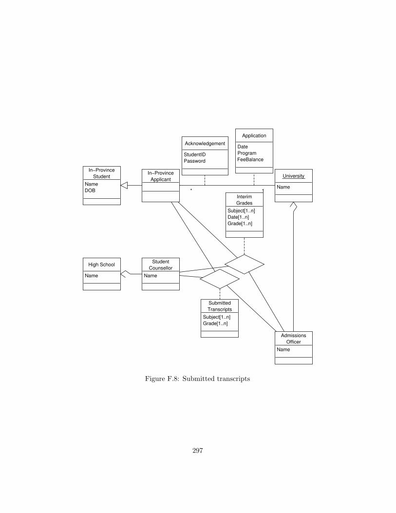
In−ProvinceStudent
NameDOB
High School
Name
University
Name1*
Application
DateProgramFeeBalance
In−ProvinceApplicant
AdmissionsOfficer
Name
StudentCounsellor
Name
SubmittedTranscripts
Subject[1..n]Grade[1..n]
InterimGrades
Subject[1..n]Date[1..n]Grade[1..n]
Acknowledgement
StudentIDPassword
Figure F.8: Submitted transcripts
297

In−ProvinceStudent
NameDOB
Teacher
Name
High School
NameCourse
Name[1..n]Type[1..n]Semester[1..n]Standing[1..n]
*
*
1..*
University
Name
1
*
Application
DateProgramFeeBalance
In−ProvinceApplicant
Ministry ofEducation
Jurisdiction
*
1
Provincial ExamStandings
Subject[1..n]Semester[1..n]Standing[1..n]
ReportedProvincial Grades
Subject[1..n]Semester[1..n]Standing[1..n]
Acknowledgement
StudentIDPassword
Figure F.9: Submitted provincial grades
298

In−ProvinceStudent
NameDOB
High School
Name
AdmissionsOfficer
Name
StudentCounsellor
Name
InterimGrades
Subject[1..n]Date[1..n]Grade[1..n]
University
Name
1..n
In−ProvinceApplicant
SelfReportedGrades
Course[1..n]Semester[1..n]Standing[1..n]Date[1..n]
Figure F.10: Self-reported grades
AdmissionsOfficer
Name
University
Name1..n
Faculty
Program[1..n]Requirements[1..n]Places[1..n]
1..n
Figure F.11: Faculties
299

Hold
UnconditionallyAccepted
Pending
ConditionallyAdmitted
PayFeeNotAdmissable
BBAAddmissable
Figure F.12: States of an applicant, incorrect
300

to change the state, it is the university or parts of the university that takeaction.
Instead, these states are states of the university, or one of its parts. Itis the university (and its parts, the faculties) that possesses all requiredattributes by rule 21 and it is the admissions officers (parts of the univer-sity) that carry out the actions required by rules 25, 26 and corollary 14.Therefore, these states must be modelled as states of the university. More-over, since the states for each applicant to the university are independent ofone another, rule 22 and corollary 16 require that sufficient attributes andassociation-class attributes are defined. This is here trivially the case, asthe university possesses the same independent set of mutual properties witheach applicant. Fig. F.13 shows a state chart depicting this interpretation.
Assuming that state chart Fig. F.13 shows (part of) the top-level statechart implies that by rules 25, 26 and corollaries 21, 22 the states are stableand the state transitions between them must be associated with an externalevent and correspond to an operation of the object/class. In each of theconcurrent regions, the second state is a composite state with four sub-states. In the UML meta-model, this corresponds to an embedded statemachine, so that these sub-states are not directly part of the top-level statechart. Thus, there does not need to be an external event or an operationof the university (or its parts) associated with the state transitions in thatcomposite state. As a consequence, there exists only one state transitionexpressing a quantitative change initiated by an external object: ’PayFee’is an event caused by the student object when the FeeBalance, a mutualproperty, is changed to zero, indicating no outstanding balance. Rules 22and 15 are satisfied as the two outer states are defined based on the attribute’FeeBalance’ while the sub-states are defined based on the attributes of theassociation classes representing transcript grades and exam marks.
Other changes to the student and the university are of qualitative nature,when the student applies and becomes an applicant, the university gains aset of state variables which span another orthogonal region in the top-levelstate chart (rules 22, 32, corollaries 15, 16). Any state transitions thatare not associated with external events must be part of a method whichrealizes an operation which is in turn caused by external events. The methodthat encompasses the state changes within the sub-state machines is theapplication procedure that is carried out by the university and its parts, i.e.the faculties and the admissions officer. It is externally induced when theuniversity receives an application from a student accompanied or followed
301

Hold
UnconditionallyAccepted
Pending
ConditionallyAdmitted
PayFee
NotAdmissable
Hold
UnconditionallyAccepted
Pending
ConditionallyAdmitted
PayFee NotAdmissable
Hold
UnconditionallyAccepted
Pending
ConditionallyAdmitted
PayFee NotAdmissable
etc...
BBAAdmissable
BBAAdmissable
BBAAdmissable
Figure F.13: States of the university302

by fee payment.
Once a student is unconditionally accepted, an admissions officer willsend an offer of acceptance to the applicant. We again suggest sub-classingsuch an applicant, for similar reasons that we sub-classed students: Onlysome of them possess the new properties and only some of them possess newbehavioural possibilities (e.g. accepting or rejecting an offer). Once all finaltranscripts and final provincial ministry grades are received, all applicantson hold and all conditionally accepted students are evaluated and becomeeither unconditionally admissible or must be rejected. In the first case, anadmissions officer sends out offers of acceptance, in the second case, a noticeof rejection is sent. The amended sequence diagram in Fig. F.14 showsthese interactions and Fig. F.15 shows the sub-classification of applicants.Note that rejected applicants are not subclassed, as they possess neitheradditional properties nor additional behaviour.
303

: Student : Teacher
*[1..n]:AttendClass
University :University
Apply
: Ministry of Education
*[1..n]:ProvincialExamination
: AdmissionsOfficer
: StudentCounsellor
*[1..3]:ReportProvincialGrades
RequestTranscripts
*[2]:SubmitTranscripts*[1..n]:RequestSendingInterimGrades
*[1..n]:SubmitInterimGrades
Self-report GradesVerifyGrades
[Student.CurrentState = UnconditionallyAccepted] OfferOfAdmission[Student.CurrentState = NotAdmisssable ] NoticeOfRejection
AcknowledgeApplication
Figure F.14: Acceptance and rejection notices
304

If the applicant cannot be unconditionally accepted, but the faculty andprogram applied to has broader based admission (BBA) requirements, theapplication is referred to faculty admissions officers for evaluations who willthen pass a recommendation to a university admission officer who will inturn notify the applicant. BBA requirements are optional properties forfaculties. However, if a faculty possesses BBA requirements, it must alsohave faculty admissions officers. This suggests a subclassification of facultieswith such properties and parts, as shown in Fig. F.16.
305

In−ProvinceStudent
NameDOB
AdmissionsOfficer
Name
In−ProvinceApplicant
AcceptedApplicant
1 1..n
Offer ofAdmisssion
DateValid UntilProgram
Figure F.15: Accepted and rejected applicants
306
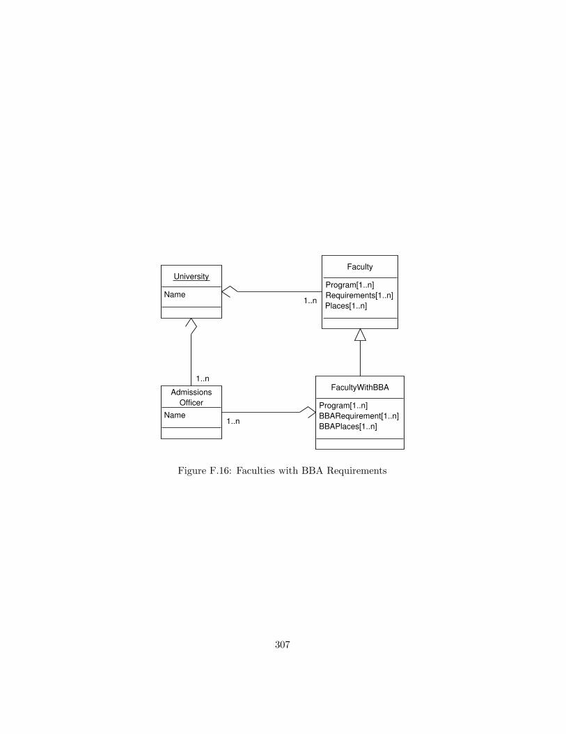
AdmissionsOfficer
Name
University
Name
1..n
Faculty
Program[1..n]Requirements[1..n]Places[1..n]
1..n
FacultyWithBBA
Program[1..n]BBARequirement[1..n]BBAPlaces[1..n]
1..n
Figure F.16: Faculties with BBA Requirements
307

: Student : Teacher*[1..n]:AttendClass
University :University
Apply
: Ministry of Education
*[1..n]:ProvincialExamination
: AdmissionsOfficer
: StudentCounsellor
*[1..3]:ReportProvincialGrades
RequestTranscripts
*[2]:SubmitTranscripts*[1..n]:RequestSendingInterimGrades
*[1..n]:SubmitInterimGrades
Self-report GradesVerifyGrades
[Student.CurrentState = UnconditionallyAccepted] OfferOfAdmission[Student.CurrentState = NotAdmisssable ] NoticeOfRejection
BBAAssessmentReq
BBAAssessmentAdvice
AcknowledgeApplication
Figure F.17: Faculties with BBA requirements, sequence diagram
308

The corresponding interactions are shown in Fig. F.17. An admissionsofficer issues a request to another admissions officer (part of a faculty) andthis officer issues a BBA assessment advice back to the first admissionsofficer.
We next turn to applicants which do not follow the standard processmodelled above. The university has agreements with the Ministries of Ed-ucation of the provinces Ontario and Alberta so that students from theseprovinces may be treated as in-province students for the purpose of applica-tion process. Another group of students are those of the US. These studentsrequire an SAT examination in order to gain admission. This is achievedthrough an interaction with the company administering the SAT tests, ETS,which will electronically transfer the scores to all universities requested bythe examinee. This is depicted in Figs. F.18 and F.19.
309

USApplicant
University
Name
ETS
SAT Scores
Scores[1..n]Universities[1..n]
Reported SATScores
Scores[1..*]
US High School
Name
School Official
Name1..n
Teacher
Name
US Student
NameDOB
[1..n]
1..n
1..n
Course
NameTypeSemesterStanding
1..n
1..n
SubmittedTranscripts
Subject[1..n]Grade[1..n]
Figure F.18: SAT scores and US applicants
310

: USApplicant ETS : ETS
*[1..n]:SAT Exam
University :University
*[1..n]: SubmitSATScoresApply
: SchoolOfficial
SubmitTranscripts
*[1..n]:AttendClass
: Teacher
Figure F.19: US applicants interaction
311

As the university is not able to receive grades in an automated electronicway from the respective ministry of education, the transcripts must be pro-vided directly from the high school, by a high school official. Other aspectsof the process and the steps involved in it are identical to the process forlocal, in-province applicants.
Another group of applicants that is involved in a different set of in-teractions, resulting in a different set of properties, are international ap-plicants. Such applicants must undergo a test of their English languagecapabilities with the company administering the standardized TOEFL test(ETS). Results are automatically forwarded to all universities requested bythe examinee. They must also submit transcripts translated by a recognizedtranslator or translation service. The interactions are shown in sequence di-agram Fig. F.20 and the resulting mutual properties are shown in the classdiagram in Fig. F.21.
312

: InternationalApplicant ETS : ETS
*[1..n]:TOEFL Exam
University :University
*[1..n]: SubmitTOEFLScoresApply
: SchoolOfficial
SubmitTranslatedTranscripts
*[1..n]:AttendClass
: Teacher : Translator
SubmitTranscripts
Figure F.20: International applicants interactions
313

Having defined the three types of applicants separately, we can abstractcommon features. International students, US students and in-province stu-dents are all students which take courses with teachers at high schools. Wetherefore suggest the generalization structure shown in Fig. F.22. Interna-tional students and US students are not distinguished based on their proper-ties. Only after they apply, once they are applicants, do they gain differentproperties, i.e. SAT scores and TOEFL scores etc. As students, all attendhigh schools and take courses leading to course grades. In-province studentson the other hand are different, as they take exams with the Ministry ofEducation.
There exist two more classes of students, out-of-province students andstudents in International Baccalaureate (IB) programs. All of their tran-scripts are submitted by their high school, but they do not require an SATexam like US applicants do. These applicants form the remainder of theclass ’Applicants’ which are not instances of the sub-classes ’in-province ap-plicant’, ’US applicant’ or ’International applicant’. Therefore, no sub-classis necessary to represent these applicants.
Based on this discussion and the generalizations shown in Fig. F.22we can simplify the previous class diagrams by making use of inheritance(Figs. F.23, F.24, F.25, F.26). The state chart in Fig. F.12 is applicable toall applicants (class ’Applicant’).
F.2 Interactions and Operations
The class diagrams developed in the previous paragraphs outline mostly thestatic structure and represent the things and their (mutual) properties, butneglect to show operations and methods of the objects and classes. Mostproperties are mutual properties which arise out of and consequently rep-resent interaction. Most of the changes are qualitative changes, expressedthrough acquisition or loss of properties. As an example, a student becomesan international applicant who becomes an accepted applicant. Only oneclass, the university, has states defined for it (Fig. F.12). These are basedon the values of intrinsic and mutual properties (represented as attributes)and changes of state represent changes to the values of attributes. Thesequantitative changes and all qualitative changes must be expressed by oper-ations of attributes in the object-oriented paradigm (rules 26, 27). Rule 30suggests that externally caused events cause an operation to be performed.
314

InternationalApplicant
University
Name
ETS
TOEFL Scores
Scores[1..n]Universities[1..n]
Reported TOEFLScores
Scores[1..*]
InternationalHigh School
Name
School Official
Name1..n
Teacher
Name
InternationalStudent
NameDOB
[1..n]
1..n
1..n
Course
NameTypeSemesterStanding
1..n
1..n
SubmittedTranscripts
Subject[1..n]Grade[1..n]
Translator
NameLicenseNumber
TranslatedTranscripts
Subject[1..n]Grade[1..n]
Figure F.21: International applicants
315

University
Name
High School
NameLanguageOfInstruction
School Official
Name1..n
Teacher
Name
[1..n]
1..n 1..n
Course
NameTypeSemesterStanding
Student
NameDOB
Applicant
Application
DateProgramFeeBalance
In−ProvinceStudent
In−ProvinceApplicant
US Applicant InternationalApplicant
StudentCounsellor
AdmissionsOfficer
Name
SubmittedTranscripts
Subject[1..n]Grade[1..n]
Acknowledgement
StudentIDPassword
Figure F.22: Generalization of applicants
We can therefore define operations based on external interaction.
A general guidelines that is applicable is based on corollary 5 and rules4 and 5 require that operations are not modelled on association classes butinstead on the participating classes representing the interacting objects.
Some operations and interactions are outside the scope of this analysis,such as the interactions within high schools that lead to the set of propertieslabelled ’Course’.
As there is very little quantitative change in the analysed domain, rules25 and 26, stating that the quantitative changes are expressible in statecharts and that the transitions of a state chart correspond to operationare not applicable. Moreover, Chapter 6 deals with interactions due toquantitative change only and is therefore to a large degree not applicable.Instead, section 4.2.4 provides us with rules 13 and 15, which, togetherwith corollary 11, govern the creation and destruction of objects due tore-classification based on loss or acquisition of (mutual) properties.
The initial interaction is that between a student and the university: Thestudent applies to the university. Once the university has acknowledged the
316

USApplicant
University
NameGradeTranslation[1..n]
ETS
SAT Scores
Scores[1..n]Universities[1..n]
Reported SATScores
Scores[1..*]
Figure F.23: US Applicants
317

In−ProvinceStudent
NameDOB
University
NameGradeTranslation[1..n]
In−ProvinceApplicant
Ministry ofEducation
Jurisdiction
*
1
Provincial ExamStandings
Subject[1..n]Semester[1..n]Standing[1..n]
ReportedProvincial Grades
Subject[1..n]Semester[1..n]Standing[1..n]
Figure F.24: In-Province Applicants
318

InternationalApplicant
University
NameGradeTranslation[1..n]
ETS
TOEFL Scores
Scores[1..n]Universities[1..n]
Reported TOEFLScores
Scores[1..*]
Translator
NameLicenseNumber
TranslatedTranscripts
Subject[1..n]Grade[1..n]
Figure F.25: International Applicants
319

AdmissionsOfficer
Name
ApplicantAcceptedApplicant
1 1..n
Offer ofAdmisssion
DateValid UntilProgram
Figure F.26: Accepted Applicants
application, the student becomes an applicant. Thus, an instance of classstudent needs to be destroyed and an instance of class applicant created withthe requisite mutual properties. The interaction ’apply’ is not caused by anexternal event to the student within the scope of this analysis, there mustnot be an operation. However, the university as receiver of the stimulusmust possess an operation which is caused by the event that is caused byreception of the stimulus. We call this operation ’Process Application’. Asthe changes are of qualitative nature, we do not provide a state chart for amethod implementing this method.
As part of the processing of an application, the university sends a mes-sage to the student with a student ID and password for services. For thestudent, this is an external event, and we provide an operation for it. Asthe student becomes an applicant once all required mutual properties areestablished, we call the operation ’BecomeApplicant’. Any method imple-menting this operation must create an instance of applicants and destroyan instance of student as per rules 15 and 13. Students also initiate, aspart of their school attendance, interaction with the ministry of interaction.For the ministry, this is an external event requiring an operation. We callthis operation ’AdministerExam’. These operations are shown in the classdiagram of Fig. F.27.
As part of an internal or ongoing process, the Ministry provides thegrades to the university (Figs. F.7, F.9). This therefore does not require anoperation for the MoE, but instead must be handled by the university inoperation ’AcceptMinistryGrades’ (Fig. F.28).
The university, as part of the operation ’ProcessApplication’ will also
320

In−ProvinceStudent
NameDOB
BecomeApplicant
University
Name
ProcessApplication1*
Application
DateProgramFeeBalance
In−ProvinceApplicant
Minisry ofEducation
Jurisdiction
AdministerExam*1
Provincial ExamStandings
Subject[1..n]Semester[1..n]Standing[1..n]
Acknowledgement
StudentIDPassword
Figure F.27: Operations of students, the university and the MoE
University
Name
ProcessApplicationAccceptMinistryGradesEvaluate
Ministry ofEducation
Jurisdiction
AdministerExam
ReportedProvincial Grades
Subject[1..n]Semester[1..n]Standing[1..n]
Figure F.28: Operations of the university
321

In−ProvinceApplicant
AdmissionsOfficer
Name
Evaluate
StudentCounsellor
Name
SubmitTranscriptsSubmitInterimGrades
SubmittedTranscripts
Subject[1..n]Grade[1..n]
InterimGrades
Subject[1..n]Date[1..n]Grade[1..n]
Figure F.29: Operations of student counsellors and admission officers
send requests for transcripts to the high school officials. For the latter, thisis an external event and must be processed by an operation, ’SupplyTran-scripts’. Student counsellors may also be asked to provide interim grades,requiring operation ’SupplyInterimGrades’ (Fig. F.29). Finally, the appli-cant and student counsellors can report grades or transcripts to the univer-sity or the admissions officers. In both cases, internal activity is caused,that of evaluating or re-evaluation an applicant with respect to the require-ments. We call these operations of the university and the admissions officers’evaluate’ (Figs. F.28, F.29).
Once the university assesses the admissibility of an applicant and decideswhether to issue an offer or rejection notice, it sends one such message tothe applicant. This is part of the operation of processing an application or
322

University
Name
ProcessApplicationAcceptMinistryGradesEvaluateReceiveSATReceiveTOEFL
ETS
AdministerSATAdministerTOEFL
Figure F.30: Operations of the university and ETS
evaluating an applicant, it is therefore not necessary to provide a method forthis. For the applicant, this is an initial external event leading to a numberof internal changes, such as accepting or rejecting an offer, etc. However,this is outside the scope of the application process under study here, so willnot be modelled.
Internal communication between different parts of the university, e.g.admissions officers of the university and admissions officers of the facultiesfor BBA admissions (see Fig. F.17), are captured by the already definedmethods. An admissions officer requesting a BBA evaluation from a facultyadmissions officer triggers the operation ’evaluate’. Conversely, once a fac-ulty admissions officer has performed the evaluation, that officer will requestan evaluation and notification of the student from the university admissionsofficer, again triggering the operation ’evaluate’.
The class diagram in Fig. F.30 shows the properties required for the uni-versity and ETS to account for external requests from US and internationalapplicants (see sequence diagrams in Figs. F.19 and F.20). Applicants, bytaking a SAT or TOEFL exam, cause an external event in the ETS object,which eventually leads to the sending of a message to the university, caus-ing an external event in that object. This causes the behaviour specified inoperation ’ReceiveSATScores’ and ’ReceiveTOEFLScores’.
323

Appendix G
Post-Test Questionnaire
G.1 UML Knowledge
UML-A
On a scale of 1 (low) to 7 (high) how do you rate yourknowledge of UML?
UML-B
For how many months have you used UML in practice(outside classes or courses)?
UML-1
An aggregation expresses a Part-Of relationship be-tween a component object and an aggregate object.(True/False)
UML-2
A subclasss inherits all the features from its superclass.(True/False)
UML-3
On a class diagram, a ternary relationship is repre-sented by a rounded rectangle. (True/False)
UML-4
Abstracting the common features among multipleclasses, as well as the relationships they participatein, is called generalization. (True/False)
324

UML-5
An object class is a set of objects that share a commonstructure and a common behavior. (True/False)
UML-6
On a class diagram, an exclamation point repre-sents a multiplicity with an infinite upper bound.(True/False)
UML-7
On a class diagram, an asocation is signified by adouple-ended arrow that connects the participatingobject classes. (True/False)
UML-8
An object is an entity that has a well-defined role inthe application domain, and has state, behaviour, andidentity. (True/False)
UML-9
When indicating the multiplicity for a role, an infiniteupper bound is denoted by a
1. Dash
2. Diamond
3. Hollow point arrow
4. Star
UML-10
In UML, a class is represented by
1. A rectangle with three compartments separatedby horizontal lines.
2. A circle in which the activity name is recorded.
3. A double-lined ellipse in which the activity nameis recorded.
4. A diamond in which the activity is recorded.
325

UML-11
Changes in the attributes of an object or in the linksan object has with other objects best defines:
1. Events
2. Operation
3. State Transition
4. Method
UML-12
A function or a service that is provided by all theinstances of class best defines
1. Encapsulation
2. Task Set
3. Operation
4. Multiplicity
UML-13
A relationship among instances of object classes bestdefines
1. Encapsulation
2. Scope
3. Association
4. Composition
UML-14
Which of the following indicates how many objectsparticipate in a given relationship?
1. Assocation role
2. Object count
3. Multiplicity
4. Association class
326

UML-15
The degree of an association relationship can be:
1. Unary
2. Binary
3. Ternary
4. All of the above
UML-16
The end of an association where it connects to a classbest describes:
1. Encapsulation
2. Scope
3. Association role
4. Composition
UML-17
Which of the following encompasses an object’s prop-erties and the values those properties have?
1. Behaviour
2. Class
3. State
4. Encapsulation
UML-18
Which of the following indicates a minimum of 0 anda maximum of 1?
1. 1 . . . 0
2. 0 . . . 1
3. 1 – 0
4. 1:M
327

UML-19
Which of the following is not a true statement?
1. An object’s behaviour depends on its state andthe operation being performed.
2. An object’s state is determined by its attributevalues and links to other objects.
3. An operation is simply an action that one ob-ject performs upon another in order to get a re-sponse.
4. Object class refers to an entity that has a well-defined role in the application domain, and hasstate, behaviour and identity.
G.2 Ease of Interpretation, Usefulness and Infor-mation Content
EOI-1 The class diagram was easy to read.EOI-2 The class diagram was clear and understandable.EOI-3 The class diagram was easy to understand.EOI-4 (R) (*) Interpreting the class diagram was frustrating.EOI-5 (*) The class diagram was simple.
EOI-6 (R)I believe that the class diagram was cumbersome tointerpret.
EOI-7 I feel comfortable with interpreting the class diagram.EOI-8 I believe that it is easy to interpret the class diagram.
EOI-9 (R)Interpreting the class diagram required a lot of mentaleffort.
EOI-10 Overall, I found the class diagram easy to interpret.
EOI-11It was easy for me to understand what the diagramwas trying to model.
EOI-12 (*) Overall, I found the class diagram was easy to use.USE-1 (*) I feel confident that my answers are correct.
USE-2The information in the class diagram was helpful foranswering the questions.
USE-3Interpreting the class diagram increased my effective-ness in answering the questions.
328

USE-4Interpreting the class diagram improved the quality ofmy answers to the questions.
USE-5Understanding the class diagram made answering thequestions easier.
USE-6Interpreting the diagram enhanced the quality of myanswers.
INFO-1I believe the diagram was an accurate representationof order processing1.
INFO-2The class diagram provided all the information re-quired to answer the questions.
INFO-3 (*)Interpreting the class diagram has provided knowledgeabout order processing2.
INFO-4 I believe the diagram showed a lot of detail.INFO-5 (*) The diagram was a good diagram.
Note 1: EOI : Ease of Interpretation; USE : Usefulness; INFO : Informa-tion content
Note 2: (R) indicates reverse coded items.
Note 3: (*) indicates the item was not included in the final instrument.
Note 4: The item names may be prefixed according to whether they referto the order processing domain or the car rental domain, e.g. CR-EOI-1refers to the first item on the Ease of Interpretation scale for the car rentaldomain.
G.3 Domain Familiarity
OP-1On a scale of 1 (low) to 7 (high) how do you rate yourknowledge of order processing procedures?
OP-2Have you ever worked in an order processing depart-ment? (yes/no)
1Car Rental, depending on the domain.2Car Rental, depending on the domain.
329

CR-1On a scale of 1 (low) to 7 (high) how do you rate yourknowledge of car rental procedures?
CR-2 Have you ever rented a car before? (yes/no)
CR-3Have you ever worked for a car rental agency?(yes/no)
330

Appendix H
Diagram ComprehensionQuestions
Order Processing Domain
OPComp-1 Is the corporate customer billed on a monthly basis?OPComp-2 Do all customers have a sales representative ?OPComp-3 Does the order show taxes paid on items?OPComp-4 Can an order contain products of different types?
OPComp-5Is a sales representative responsible for a producttype?
OPComp-6 Can customers pay for their orders by credit card?OPComp-7 Does the order total show discounts?OPComp-8 Do corporate customers receive payment reminders?
OPComp-9Can a customer order the same products multipletimes?
OPComp-10 Can orders be prepaid?
OPComp-11Can a corporate customer have multiple sales repre-sentatives?
Car Rental Domain
CRComp-1Can the pick-up location for cars be different from thedrop-off location?
331

CRComp-2 Can customers reserve multiple cars?
CRComp-3Are the license plate numbers of rented vehiclesrecorded?
CRComp-4 Can a reservation be billed multiple times?
CRComp-5Is there a minimum age for customers to rent a vehi-cle?
CRComp-6Can customers purchase insurance for the vehicle theyrent?
CRComp-7Does the company charge freight and inspection forsold cars?
CRComp-8 Does the invoice show taxes?CRComp-9 Can an invoice be produced without renting a car?
332

Appendix I
Problem Solving Questions
Order Processing Domain
OPProb-1Suppose that an important customer needs to orderproducts urgently? What problems could he/she face?
OPProb-2Suppose that a shipment does not contain all orderedproducts. What could have happened?
OPProb-3Suppose the warehouse has run out of items and anorder cannot be fulfilled. How could this have hap-pened?
OPProb-4Suppose two customer’s orders are mixed up. Whatcould have happened?
OPProb-5Suppose that a customer wants to change their order.What problems could this pose?
OPProb-6Suppose the customer wannts to know the expecteddelivery date of his order? What problems might beexperienced when replying to the customer?
OPProb-7Suppose a customer is not billed for some products.What could have happened?
Car Rental Domain
CRProb-1Suppose that a customer arrives for pick-up but no caris available. What could have happened?
333

CRProb-2Suppose a customer receives two invoices. What couldhave happened?
CRProb-3Suppose a car which is reserved for a customer is beingsold at auction. How could this have happened?
CRProb-4Suppose a customer is not billed for a reservation?What could have happened?
CRProb-5Suppose that a customer wants to extend his rentalperiod. What could go wrong?
334

Appendix J
Experimental Results(Extended Analysis)
J.1 ANCOVA (Step-wise Inclusion of Variables)
In order to arrive at a more parsimonious explanatory model than the fullANCOVA model presented in Section 11.8.4, non-significant factors and co-variates were omitted from the model and interaction effects of UML knowl-edge were considered. This supplementary analysis reveals that only thevariables ”Rules”, ”Group” and ”UML.TTL” need to be considered.
Error: Subject
Df Sum Sq Mean Sq
Rules 1 1.3804 1.3804
Error: Within
Df Sum Sq Mean Sq F value Pr(>F)
Rules 2 3.574 1.787 4.0133 0.0212222 *
Group 2 5.889 2.944 6.6126 0.0020477 **
UML.TTL 1 5.002 5.002 11.2348 0.0011535 **
Rules:Group 4 9.324 2.331 5.2352 0.0007447 ***
Residuals 95 42.299 0.445
---
Signif. codes: 0 ***’ 0.001 **’ 0.01 *’ 0.05 .’ 0.1 ’ 1
335

Overall, the fit of this reduced model is R2 = .3731 which is onlymarginally smaller than the goodness of fit of the complete model, sug-gesting that this more parsimonious model offers as good an explanation forthe observed data.
To further assess the results and confirm the more parsimonious model,it was decided to successively include factors and covariates in the modelwhile the model quality increases. The statistical package R provides aprocedure for doing this, based on the Akaike Information Criterion (AIC)which assesses model fit and is a function of the number of model parametersto be fitted so as to avoid overfitting. With this interpretation, a smaller AICis better (Pinheiro and Bates, 2000). Factors and covariates are included aslong as the AIC of the resulting model can be lowered.
Start: AIC= -45.89
Prob ~ 1
Df Sum of Sq RSS AIC
+ UML.TTL 1 7.215 60.253 -55.878
+ Group 2 6.544 60.924 -52.704
+ Rules 2 4.112 63.356 -48.555
+ UML.A 1 2.517 64.952 -47.919
+ Information 1 2.417 65.051 -47.756
<none> 67.468 -45.889
+ Time 1 0.952 66.516 -45.396
+ Usefulness 1 0.730 66.739 -45.041
+ SelfAssess 1 0.265 67.203 -44.306
+ Domain 1 0.195 67.274 -44.195
+ Comp 1 0.095 67.373 -44.038
+ Interpretation 1 5.326e-05 67.468 -43.889
Step: AIC= -55.88
Prob ~ UML.TTL
Df Sum of Sq RSS AIC
+ Group 2 4.386 55.868 -59.888
+ Rules 2 3.556 56.697 -58.327
+ Time 1 1.342 58.911 -56.265
<none> 60.253 -55.878
+ Information 1 1.066 59.187 -55.770
336

+ Usefulness 1 0.615 59.638 -54.966
+ SelfAssess 1 0.383 59.870 -54.554
+ UML.A 1 0.318 59.935 -54.439
+ Domain 1 0.195 60.058 -54.221
+ Comp 1 0.036 60.217 -53.941
+ Interpretation 1 0.001 60.252 -53.879
- UML.TTL 1 7.215 67.468 -45.889
Step: AIC= -59.89
Prob ~ UML.TTL + Group
Df Sum of Sq RSS AIC
+ Rules 2 4.071 51.797 -63.907
<none> 55.868 -59.888
+ SelfAssess 1 0.709 55.159 -59.242
+ Usefulness 1 0.570 55.297 -58.976
+ Information 1 0.530 55.337 -58.899
+ Time 1 0.455 55.413 -58.754
+ Domain 1 0.195 55.673 -58.258
+ UML.A 1 0.147 55.721 -58.167
+ Interpretation 1 0.070 55.798 -58.021
+ Comp 1 0.008 55.859 -57.904
- Group 2 4.386 60.253 -55.878
- UML.TTL 1 5.056 60.924 -52.704
Step: AIC= -63.91
Prob ~ UML.TTL + Group + Rules
Df Sum of Sq RSS AIC
<none> 51.797 -63.907
+ SelfAssess 1 0.949 50.848 -63.868
+ Comp 1 0.776 51.021 -63.507
+ Time 1 0.663 51.134 -63.273
+ Information 1 0.519 51.278 -62.975
+ Usefulness 1 0.229 51.568 -62.378
+ Domain 1 0.195 51.602 -62.307
+ Interpretation 1 0.063 51.734 -62.036
+ UML.A 1 0.002 51.795 -61.912
- Rules 2 4.071 55.868 -59.888
- Group 2 4.900 56.697 -58.327
337

- UML.TTL 1 4.829 56.626 -56.460
Call:
lm(formula = Prob ~ UML.TTL + Group + Rules, data = gData)
Coefficients:
(Intercept) UML.TTL GroupC GroupC2
0.01521 0.11382 -0.46989 -0.07550
RulesR RulesR2
0.32309 -0.15017
This procedure produces a model with the same factors and covariatesas the reduced model assessed with ANCOVA in Sec. 11.8.4. The algorithmadds that element to the model which increases the model quality (decreasesthe AIC) most. Thus, in the first step, ”UML.TTL” is included, followedby ”Group” and ”Rules”. No interaction effects are considered.
J.2 Linear Mixed Effects Modelling (Analysis ofResults)
Linear mixed effect (LME) models (Pinheiro and Bates, 2000) work by (re-stricted) maximum likelihood fitting of parameters to the data and allowmodelling of nested random and nested fixed effects within the same model.Similar to the ANCOVA methodology employed in Sec. 11.8.4, the analysisbegins with a complete model including all factors and covariates, includ-ing second order factor interaction terms. Goodness of the model is againassessed using the AIC criterion discussed above.
Linear mixed-effects model fit by REML
Data: gData
AIC BIC logLik
271.7827 330.1223 -111.8913
Random effects:
Formula: ~1 | Subject
(Intercept) Residual
StdDev: 0.4966753 0.4682717
338
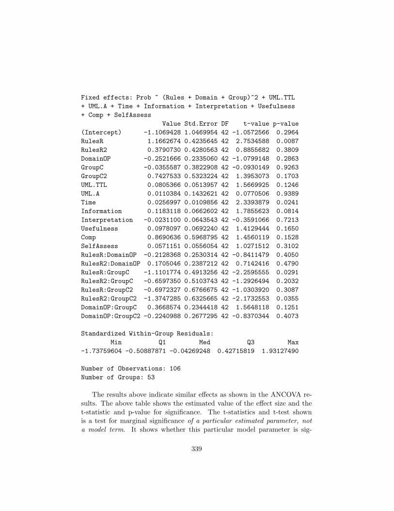
Fixed effects: Prob ~ (Rules + Domain + Group)^2 + UML.TTL
+ UML.A + Time + Information + Interpretation + Usefulness
+ Comp + SelfAssess
Value Std.Error DF t-value p-value
(Intercept) -1.1069428 1.0469954 42 -1.0572566 0.2964
RulesR 1.1662674 0.4235645 42 2.7534588 0.0087
RulesR2 0.3790730 0.4280563 42 0.8855682 0.3809
DomainOP -0.2521666 0.2335060 42 -1.0799148 0.2863
GroupC -0.0355587 0.3822908 42 -0.0930149 0.9263
GroupC2 0.7427533 0.5323224 42 1.3953073 0.1703
UML.TTL 0.0805366 0.0513957 42 1.5669925 0.1246
UML.A 0.0110384 0.1432621 42 0.0770506 0.9389
Time 0.0256997 0.0109856 42 2.3393879 0.0241
Information 0.1183118 0.0662602 42 1.7855623 0.0814
Interpretation -0.0231100 0.0643543 42 -0.3591066 0.7213
Usefulness 0.0978097 0.0692240 42 1.4129444 0.1650
Comp 0.8690636 0.5968795 42 1.4560119 0.1528
SelfAssess 0.0571151 0.0556054 42 1.0271512 0.3102
RulesR:DomainOP -0.2128368 0.2530314 42 -0.8411479 0.4050
RulesR2:DomainOP 0.1705046 0.2387212 42 0.7142416 0.4790
RulesR:GroupC -1.1101774 0.4913256 42 -2.2595555 0.0291
RulesR2:GroupC -0.6597350 0.5103743 42 -1.2926494 0.2032
RulesR:GroupC2 -0.6972327 0.6766675 42 -1.0303920 0.3087
RulesR2:GroupC2 -1.3747285 0.6325665 42 -2.1732553 0.0355
DomainOP:GroupC 0.3668574 0.2344418 42 1.5648118 0.1251
DomainOP:GroupC2 -0.2240988 0.2677295 42 -0.8370344 0.4073
Standardized Within-Group Residuals:
Min Q1 Med Q3 Max
-1.73759604 -0.50887871 -0.04269248 0.42715819 1.93127490
Number of Observations: 106
Number of Groups: 53
The results above indicate similar effects as shown in the ANCOVA re-sults. The above table shows the estimated value of the effect size and thet-statistic and p-value for significance. The t-statistics and t-test shownis a test for marginal significance of a particular estimated parameter, nota model term. It shows whether this particular model parameter is sig-
339

nificantly different than the baseline of the factor. The results show thatdiagrams conforming to rules (”R”) have a significantly (p=.0087) differenteffect on problem solving performance than the other two types of diagrams(”N” and ”R2”). Also, the subjects in group ”C” interpreting diagrams oftype ”R” behave differently (p=.0291) than other combinations of subjectgroups and diagram types. Pinheiro and Bates (2000) suggest that an F-testfor inclusion of model elements provides a better criterion:
numDF denDF F-value p-value
(Intercept) 1 42 361.5242 <.0001
Rules 2 42 2.8853 0.0670
Domain 1 42 0.8879 0.3514
Group 2 42 4.7220 0.0141
UML.TTL 1 42 6.7755 0.0127
UML.A 1 42 0.0032 0.9549
Time 1 42 2.1374 0.1512
Information 1 42 3.0173 0.0897
Interpretation 1 42 0.0335 0.8556
Usefulness 1 42 2.2705 0.1393
Comp 1 42 0.5162 0.4764
SelfAssess 1 42 0.6216 0.4349
Rules:Domain 2 42 0.6873 0.5085
Rules:Group 4 42 2.8122 0.0372
Domain:Group 2 42 3.2396 0.0492
These results indicate that the factor ”Rules” tends towards significancewhile confirming that ”Group” and ”UML.TTL” are significant model ele-ments. Similarly, the domain is not significant but the interaction of Rulesand Group is. These results are in accord with those obtained by the fullANCOVA model in Sec. 11.8.4.
In order to find the most parsimonious model to explain the data, one canfollow a similar procedure as in the ANCOVA based analysis in AppendixJ.1. Model elements can be included and the resulting change in goodnessof fit as per the AIC criterion is assessed. Following this procedure leads tothe same reduced model that was arrived at in the ANCOVA case.
340

J.3 Verification of Assumptions
Pinheiro and Bates (2000) point out two main assumptions for LME models:(1) The within group errors (here: within subject errors) are IID1 with zeromean and are homoscedastic2. They must also be independent of the randomeffects. (2) The random effects are normally distributed and independentfor different groups. These two assumptions must also hold for an ANOVAprocedure to produce valid results. The following paragraphs follow theprocedure outlined in (Pinheiro and Bates, 2000).
The first assumption can be assessed by examining the within-subjectresiduals as they provide surrogates for the error terms. The boxplot inFig. J.1 shows that the residuals are independent for different subjects andappear to be centered around a mean of zero. Figures J.2 through J.4 plotthe residuals against the fitted values for different factor levels of ”Group”,”Domain”, and ”Rules” respectively.
None of these plots indicate different residuals within different sub-samples. Heteroscedasticity is also formally evaluated by comparing dif-ferent models. The base model analyzed above is compared against modelswhich allow for heteroscedasticity between different sample subgroups:
> fitted1a <-
update (fitted1, weights=varIdent(form = ~ 1 | Group))
> anova(fitted1, fitted1a)
Model df AIC logLik Test L.Ratio p-value
fitted1 1 24 271.7827 -111.8914
fitted1a 2 26 270.7511 -109.3756 1 vs 2 5.03157 0.0808
> #
> fitted1b <-
update (fitted1, weights=varIdent(form = ~ 1 | Domain))
> anova(fitted1, fitted1b)
Model df AIC logLik Test L.Ratio p-value
fitted1 1 24 271.7827 -111.8914
fitted1b 2 25 273.4269 -111.7135 1 vs 2 0.3557705 0.5509
> #
> fitted1c <-
update (fitted1, weights=varIdent(form = ~ 1 | Rules))
1Independent and identically distributed.2Equal variance
341

Residuals
Sub
ject
21184939243228472033502
198
17304153294
27262251162315314811403835436
143
427
3437461236459
25521315
1044
−0.5 0 0.5 1
Figure J.1: Box plot of residuals of LME fit
342

Fitted values
Res
idua
ls
−0.5
0
0.5
1
1 2 3
3 C
C2
Figure J.2: Residuals against fitted values by group
343

Fitted values
Res
idua
ls
−0.5
0
0.5
1
1 2 3
CR
−0.5
0
0.5
1OP
Figure J.3: Residuals against fitted values by domain
344

Fitted values
Res
idua
ls
−0.5
0
0.5
1
1 2 3
N R
R2
Figure J.4: Residuals against fitted values by type of diagram
345

> anova(fitted1, fitted1c)
Model df AIC logLik Test L.Ratio p-value
fitted1 1 24 271.7827 -111.8914
fitted1c 2 26 275.0048 -111.5024 1 vs 2 0.7778486 0.6778
None of the differences are statistically significant. While there ap-pear to be indications for different variances between the groups of subjects(p=.0808), the differences in model quality as measured by the AIC crite-rion do not suggest any practical significance of such differences. Overall,the residuals appear small which indicates a good fit of the fitted with theobserved values as shown in Fig. J.5.
Normality of the residuals is assessed by plotting them against the quan-tiles of the normal standard distribution, as shown in Figures J.6 throughJ.9, for the total sample and again for sub-samples by factor levels. Theresulting plots show that the normality assumption is justified, indicatedby the relatively straight and symmetric pattern and clustering towards thecenter.
A similar plot can be done for the random effects of each subject, shownin Fig. J.10. This shows that the normality assumption for random effectsis justified.
J.4 Equivalence of Diagrams
One of the main assumptions was that our models should be informationallyequivalent with respect to information relevant to the task. This is assessedby analyzing the effect of the different model types on the factors InformationContent, Usability and Ease of Interpretation. This is done using a standardANOVA procedure including ”Domain”, ”Group” and ”Rules” together withsecond order interactions as independent variables (Appendix K.8).
• Information Content
Error: Subject
Df Sum Sq Mean Sq
Rules 1 0.85165 0.85165
Error: Within
346

Fitted values
Pro
b
1
2
3
4
1 2 3
Figure J.5: Fitted values against observed values
347

Residuals
Qua
ntile
s of
sta
ndar
d no
rmal
43
8
49
−2
−1
0
1
2
−0.5 0 0.5 1
Figure J.6: Residuals against standard normal
348

Residuals
Qua
ntile
s of
sta
ndar
d no
rmal
8
−2
−1
0
1
2
−0.5 0 0.5 1
3 C
43
49
C2
Figure J.7: Residuals against standard normal by group
349

Residuals
Qua
ntile
s of
sta
ndar
d no
rmal
43
−2
−1
0
1
2
−0.5 0 0.5 1
CR
8
49
−2
−1
0
1
2
OP
Figure J.8: Residuals against standard normal by domain
350

Residuals
Qua
ntile
s of
sta
ndar
d no
rmal
43
−2
−1
0
1
2
−0.5 0 0.5 1
N
8
49
R
R2
Figure J.9: Residuals against standard normal by type of diagram
351
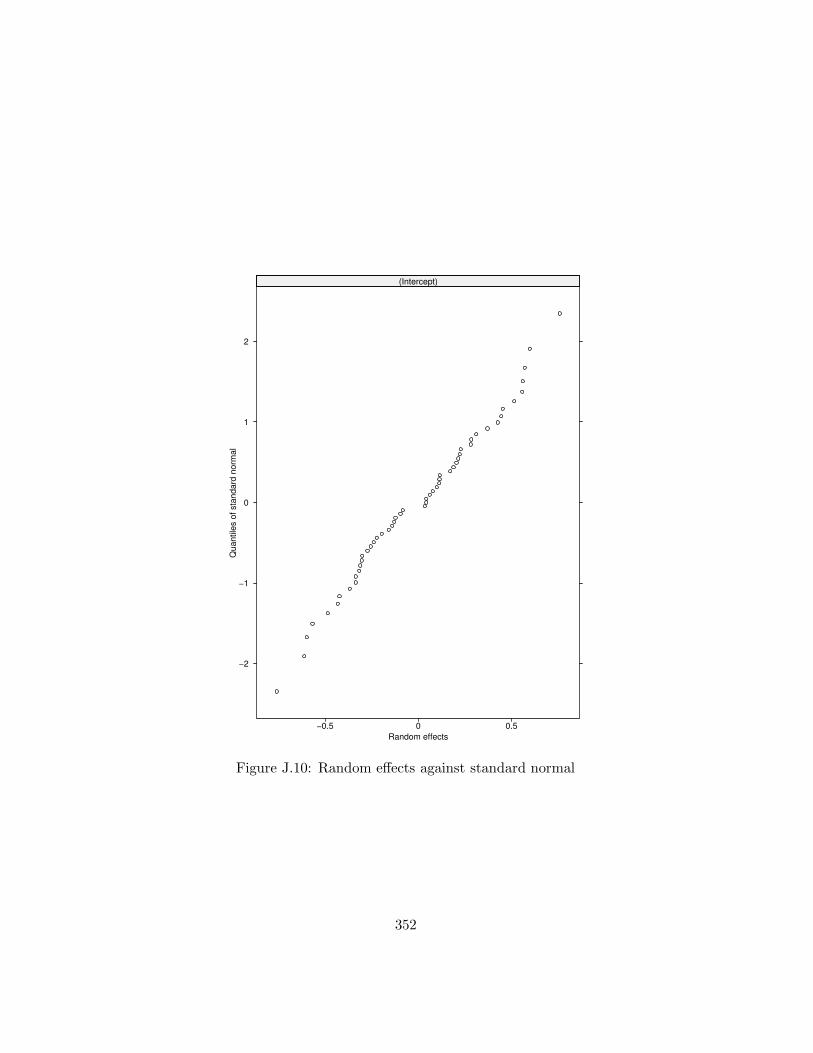
Random effects
Qua
ntile
s of
sta
ndar
d no
rmal
−0.5 0 0.5
−2
−1
0
1
2
(Intercept)
Figure J.10: Random effects against standard normal
352

Df Sum Sq Mean Sq F value Pr(>F)
Rules 2 0.264 0.132 0.1242 0.883324
Domain 1 1.053e-31 1.053e-31 9.923e-32 1.000000
Group 2 10.629 5.315 5.0064 0.008655 **
Rules:Domain 2 0.787 0.394 0.3708 0.691208
Rules:Group 4 6.428 1.607 1.5139 0.204723
Domain:Group 2 0.741 0.370 0.3489 0.706374
Residuals 91 96.604 1.062
• Usefulness
Error: Subject
Df Sum Sq Mean Sq
Rules 1 0.72032 0.72032
Error: Within
Df Sum Sq Mean Sq F value Pr(>F)
Rules 2 2.460 1.230 1.1406 0.3241
Domain 1 9.434e-11 9.434e-11 8.750e-11 1.0000
Group 2 0.414 0.207 0.1921 0.8256
Rules:Domain 2 4.682 2.341 2.1710 0.1199
Rules:Group 4 5.628 1.407 1.3049 0.2742
Domain:Group 2 1.504 0.752 0.6976 0.5004
Residuals 91 98.116 1.078
• Ease of Interpretation
Error: Subject
Df Sum Sq Mean Sq
Rules 1 0.28487 0.28487
Error: Within
Df Sum Sq Mean Sq F value Pr(>F)
Rules 2 10.801 5.400 5.1047 0.007922 **
Domain 1 9.434e-11 9.434e-11 8.917e-11 0.999992
Group 2 2.624 1.312 1.2402 0.294167
Rules:Domain 2 1.675 0.837 0.7915 0.456275
Rules:Group 4 5.840 1.460 1.3801 0.247065
Domain:Group 2 0.500 0.250 0.2362 0.790094
Residuals 91 96.272 1.058
353

Appendix K
Scripts for StatisticalAnalysis
This appendix contains the S-programs (scripts in the S language for use inthe R statistics package) used for the statistical analyses in this thesis.
K.1 Card sorting, Round 2, Initial
# ###############################################
# Joerg Evermann, 2003
#
# S program for cardsorting analysis
# ###############################################
#
# ##########################
# Define the function for Cohen’s Kappa
#
kappaFor2 <- function(r1, r2, na.method = "na.rm")
{
f1 <- ordered(r1)
f2 <- ordered(r2)
levels(f1) <- levels(ordered(c(r1, r2)))
levels(f2) <- levels(ordered(c(r1, r2)))
if (na.method == "na.rm")
na.rm <- T
354

else na.rm <- F
ttab <- xtabs( ~ f1+f2, cbind(r1, r2),
drop.unused.levels=FALSE)
tsum <- sum(ttab, na.rm = na.rm)
ttab <- ttab/tsum
tm1 <- apply(ttab, 1, sum, na.rm = na.rm)
tm2 <- apply(ttab, 2, sum, na.rm = na.rm)
agreeP <- sum(diag(ttab), na.rm = na.rm)
chanceP <- sum(tm1 * tm2, na.rm = na.rm)
kappa2 <- (agreeP - chanceP)/(1 - chanceP)
kappaSE <- 1/((1 - chanceP) * sqrt(tsum))
* sqrt(chanceP + chanceP^2
- sum(tm1 * tm2 * (tm1 + tm2), na.rm = na.rm))
kz <- kappa2/kappaSE
kp <- 2 * (1 - pnorm(kz))
ans <- c(kappa2, kappaSE, kz, kp)
names(ans) <- c("kappa", "S.E.", "z.stat", "p.value")
return(ans)
}
#
# ###########################
# Read the data file
#
data0 <- read.csv("cardsorting_round2.csv",
header=TRUE, row.names=1)
data <- as.matrix(data0[,c(1:23)])
#
kappas <- c(1:105)*0
count <- 1
#
# ###########################
# Compute all pairwise agreements
#
for(i in 1:14){
for(j in (i+1):15){
kappas[count] <- kappaFor2(data[i,], data[j,])
print(kappas[count])
print(c(count, i, j, kappas[count]))
count <- count + 1
}
355

}
#
# ###########################
# Compute max, mean and min of
# the pairwise agreements
#
kappamax <- max(kappas)
kappaavg <- mean(kappas)
kappamin <- min(kappas)
#
print(c(kappamin, kappamax, kappaavg))
K.2 Card sorting, Round 2, After refinement
# ################################################
# Joerg Evermann, 2003
#
# S Program for analysis of second round
# cardsorting data
# ################################################
#
# Define function for Cohen’s Kappa
#
kappaFor2 <- function(r1, r2, na.method = "na.rm")
{
f1 <- ordered(r1)
f2 <- ordered(r2)
levels(f1) <- levels(ordered(c(r1, r2)))
levels(f2) <- levels(ordered(c(r1, r2)))
if (na.method == "na.rm")
na.rm <- T
else na.rm <- F
ttab <- xtabs( ~ f1+f2, cbind(r1, r2),
drop.unused.levels=FALSE)
tsum <- sum(ttab, na.rm = na.rm)
ttab <- ttab/tsum
tm1 <- apply(ttab, 1, sum, na.rm = na.rm)
tm2 <- apply(ttab, 2, sum, na.rm = na.rm)
356

agreeP <- sum(diag(ttab), na.rm = na.rm)
chanceP <- sum(tm1 * tm2, na.rm = na.rm)
kappa2 <- (agreeP - chanceP)/(1 - chanceP)
kappaSE <- 1/((1 - chanceP) * sqrt(tsum))
* sqrt(chanceP + chanceP^2
- sum(tm1 * tm2 * (tm1 + tm2), na.rm = na.rm))
kz <- kappa2/kappaSE
kp <- 2 * (1 - pnorm(kz))
ans <- c(kappa2, kappaSE, kz, kp)
names(ans) <- c("kappa", "S.E.", "z.stat"
, "p.value")
return(ans)
}
#
# #######################
# Read data file
#
data0 <- read.csv("cardsorting_round2.csv",
header=TRUE, row.names=1)
i <- c(1, 2, 4, 5, 7, 9, 10, 11, 13, 14, 15, 16,
17, 19, 20, 21, 23)
data <- as.matrix(data0[,i])
#
# #######################
# Compute all pairwise agreements
#
kappas <- c(1:105)*0
count <- 1
for(i in 1:14){
for(j in (i+1):15){
print(kappas[count])
kappas[count] <- kappaFor2(data[i,], data[j,])
print(c(count, i, j, kappas[count]))
count <- count + 1
}
}
# #######################
# Compute max, mean and min
#
357

kappamax <- max(kappas)
kappaavg <- mean(kappas)
kappamin <- min(kappas)
#
print(c(kappamin, kappamax, kappaavg))
K.3 Pilot Test
# ###############################################
# Joerg Evermann, 2003
#
# Compute scale reliabilities from pilot test data
# ###############################################
#
# Read data from file
#
data0 <- read.csv("results_fall02.csv", header=TRUE,
row.names=1)
#
# ######################
# Select different proposed
# scales, for two diagrams
# separately
#
i1 <- c("Q1.1", "Q1.2", "Q1.4", "Q1.9", "Q1.10",
"Q1.11", "Q1.13", "Q1.14", "Q1.16")
j1 <- c("Q1.15", "Q1.17", "Q1.19", "Q1.21", "Q1.23")
k1 <- c("Q1.5", "Q1.7", "Q1.20")
#
i2 <- c("Q2.1", "Q2.2", "Q2.4", "Q2.9", "Q2.10",
"Q2.11", "Q2.13", "Q2.14", "Q2.16")
j2 <- c("Q2.15", "Q2.17", "Q2.19", "Q2.21", "Q2.23")
k2 <- c("Q2.5", "Q2.7", "Q2.20")
#
# ######################
# Compute reliabilities
# for each of the six
# scales
358

#
data <- as.matrix(data0[,i1])
nv1 <- ncol(data)
alpha <- (nv1/(nv1-1))*(1 - sum(apply(data,2,var))
/var(apply(data,1,sum)))
print(c("Diagram 1, Ease of Interpretation:", alpha))
print(cor(data))
data <- as.matrix(data0[,j1])
nv1 <- ncol(data)
alpha <- (nv1/(nv1-1))*(1 - sum(apply(data,2,var))
/var(apply(data,1,sum)))
print(c("Diagram 1, Usefulness:", alpha))
print(cor(data))
data <- as.matrix(data0[,k1])
nv1 <- ncol(data)
alpha <- (nv1/(nv1-1))*(1 - sum(apply(data,2,var))
/var(apply(data,1,sum)))
print(c("Diagram 1, Information Content:", alpha))
print(cor(data))
data <- as.matrix(data0[,i2])
nv1 <- ncol(data)
alpha <- (nv1/(nv1-1))*(1 - sum(apply(data,2,var))
/var(apply(data,1,sum)))
print(c("Diagram 2, Ease of Interpretation:", alpha))
print(cor(data))
data <- as.matrix(data0[,j2])
nv1 <- ncol(data)
alpha <- (nv1/(nv1-1))*(1 - sum(apply(data,2,var))
/var(apply(data,1,sum)))
print(c("Diagram 2, Usefulness:", alpha))
print(cor(data))
data <- as.matrix(data0[,k2])
nv1 <- ncol(data)
alpha <- (nv1/(nv1-1))*(1 - sum(apply(data,2,var))
/var(apply(data,1,sum)))
359

print(c("Diagram 2, Information Content:", alpha))
print(cor(data))
# ######################
# Combine the data from the two diagrams for
# each scale, then compute reliabilites
# from the combined data set
#
data1 <- as.matrix(data0[, i1])
data2 <- as.matrix(data0[, i2])
nc <- ncol(data1)
nr <- nrow(data1)+nrow(data2)
data3 <- t(array(c(t(data1), t(data2)), dim=c(nc, nr)))
alpha <- (nc/(nc-1))*(1 - sum(apply(data3,2,var))
/var(apply(data3,1,sum)))
print(c("Total, Ease of Interpretation:", alpha))
print(cor(data3))
data1 <- as.matrix(data0[, j1])
data2 <- as.matrix(data0[, j2])
nc <- ncol(data1)
nr <- nrow(data1)+nrow(data2)
data3 <- t(array(c(t(data1), t(data2)), dim=c(nc, nr)))
alpha <- (nc/(nc-1))*(1 - sum(apply(data3,2,var))
/var(apply(data3,1,sum)))
print(c("Total, Usefulness:", alpha))
print(cor(data3))
data1 <- as.matrix(data0[, k1])
data2 <- as.matrix(data0[, k2])
nc <- ncol(data1)
nr <- nrow(data1)+nrow(data2)
data3 <- t(array(c(t(data1), t(data2)), dim=c(nc, nr)))
alpha <- (nc/(nc-1))*(1 - sum(apply(data3,2,var))
/var(apply(data3,1,sum)))
print(c("Total, Information Content:", alpha))
print(cor(data3))
library(mva)
#
360

# ######################
# Arrange data for factor analysis
#
i1 <- c("Q1.1", "Q1.2", "Q1.4", "Q1.9", "Q1.10",
"Q1.11", "Q1.13", "Q1.14", "Q1.16", "Q1.15", "Q1.17",
"Q1.19", "Q1.21", "Q1.23", "Q1.5", "Q1.7", "Q1.20")
i2 <- c("Q2.1", "Q2.2", "Q2.4", "Q2.9", "Q2.10",
"Q2.11", "Q2.13", "Q2.14", "Q2.16", "Q2.15", "Q2.17",
"Q2.19", "Q2.21", "Q2.23", "Q2.5", "Q2.7", "Q2.20")
data1 <- data0[, i1]
data2 <- data0[, i2]
nc <- ncol(data1)
nr <- nrow(data1)+nrow(data2)
data3 <- t(array(c(t(data1), t(data2)), dim=c(nc, nr)))
colnames(data3) <- i1
# ########################
# Perform factor extraction with varimax
# rotation for the data for first and
# second diagram and for the combined
# data set
#
fa <- factanal(data3, factors=1, rotation="varimax")
print.factanal(fa, digits=3, cutoff=.1, sort=TRUE)
fa <- factanal(data3, factors=2, rotation="varimax")
print.factanal(fa, digits=3, cutoff=.1, sort=TRUE)
fa <- factanal(data3, factors=3, rotation="varimax")
print.factanal(fa, digits=3, cutoff=.1, sort=TRUE)
K.4 Interrater Reliabilities
# ################################################
# Joerg Evermann, 2003
#
# Anlysis of interrater agreement for problem
# solving questions
361

# ################################################
#
# Define function for Cohen’s Kappa
#
kappaFor2 <- function(r1, r2, na.method = "na.rm")
{
f1 <- ordered(r1)
f2 <- ordered(r2)
levels(f1) <- levels(ordered(c(r1, r2)))
levels(f2) <- levels(ordered(c(r1, r2)))
if (na.method == "na.rm")
na.rm <- T
else na.rm <- F
ttab <- xtabs( ~ f1+f2, cbind(r1, r2),
drop.unused.levels=FALSE)
tsum <- sum(ttab, na.rm = na.rm)
ttab <- ttab/tsum
tm1 <- apply(ttab, 1, sum, na.rm = na.rm)
tm2 <- apply(ttab, 2, sum, na.rm = na.rm)
agreeP <- sum(diag(ttab), na.rm = na.rm)
chanceP <- sum(tm1 * tm2, na.rm = na.rm)
kappa2 <- (agreeP - chanceP)/(1 - chanceP)
kappaSE <- 1/((1 - chanceP) * sqrt(tsum))
* sqrt(chanceP + chanceP^2
- sum(tm1 * tm2 * (tm1 + tm2), na.rm = na.rm))
kz <- kappa2/kappaSE
kp <- 2 * (1 - pnorm(kz))
ans <- c(kappa2, kappaSE, kz, kp)
names(ans) <- c("kappa", "S.E.", "z.stat",
"p.value")
return(ans)
}
#
# #########################
# Read the data file
#
data0 <- read.csv("results_for_interrater.csv", header=TRUE)
data <- as.matrix(data0)
#
# #########################
362

# Compute kappa for each question
#
kappa1 <- kappaFor2(data[,"CRProb.1.1"], data[,"CRProb.1.2"])
kappa2 <- kappaFor2(data[,"CRProb.2.1"], data[,"CRProb.2.2"])
kappa3 <- kappaFor2(data[,"CRProb.3.1"], data[,"CRProb.3.2"])
kappa4 <- kappaFor2(data[,"CRProb.4.1"], data[,"CRProb.4.2"])
kappa5 <- kappaFor2(data[,"CRProb.5.1"], data[,"CRProb.5.2"])
kappa6 <- kappaFor2(data[,"OPProb.1.1"], data[,"OPProb.1.2"])
kappa7 <- kappaFor2(data[,"OPProb.2.1"], data[,"OPProb.2.2"])
kappa8 <- kappaFor2(data[,"OPProb.3.1"], data[,"OPProb.3.2"])
kappa9 <- kappaFor2(data[,"OPProb.4.1"], data[,"OPProb.4.2"])
kappa10 <- kappaFor2(data[,"OPProb.5.1"], data[,"OPProb.5.2"])
kappa11 <- kappaFor2(data[,"OPProb.6.1"], data[,"OPProb.6.2"])
kappa12 <- kappaFor2(data[,"OPProb.7.1"], data[,"OPProb.7.2"])
#
# ##########################
# Print the kappa values
#
print(kappa1)
print(kappa2)
print(kappa3)
print(kappa4)
print(kappa5)
print(kappa6)
print(kappa7)
print(kappa8)
print(kappa9)
print(kappa10)
print(kappa11)
print(kappa12)
K.5 Scale Reliabilities
labelapp:scales.R
# ################################################
# Joerg Evermann, 2003
#
363

# Scale reliabilities from the final data set
# ################################################
#
# Read data from file and separate the scales
#
data0 <- read.csv("results_for_scales.csv",
header=TRUE)
i1 <- c("CRC.1", "CRC.2", "CRC.4", "CRC.9", "CRC.10",
"CRC.11", "CRC.13", "CRC.14", "CRC.16")
j1 <- c("CRC.15", "CRC.17", "CRC.19", "CRC.21", "CRC.23")
k1 <- c("CRC.5", "CRC.7", "CRC.20")
i2 <- c("OPC.1", "OPC.2", "OPC.4", "OPC.9", "OPC.10",
"OPC.11", "OPC.13", "OPC.14", "OPC.16")
j2 <- c("OPC.15", "OPC.17", "OPC.19", "OPC.21", "OPC.23")
k2 <- c("OPC.5", "OPC.7", "OPC.20")
#
# ########################
# Compute Cronbach’s alpha for the six scales
#
data <- as.matrix(data0[,i1])
nv1 <- ncol(data)
alpha <- (nv1/(nv1-1))*(1 - sum(apply(data,2,var))
/var(apply(data,1,sum)))
print(c("Car Rental, Ease of Interpretation:", alpha))
#
data <- as.matrix(data0[,j1])
nv1 <- ncol(data)
alpha <- (nv1/(nv1-1))*(1 - sum(apply(data,2,var))
/var(apply(data,1,sum)))
print(c("Car Rental, Usefulness:", alpha))
#
data <- as.matrix(data0[,k1])
nv1 <- ncol(data)
alpha <- (nv1/(nv1-1))*(1 - sum(apply(data,2,var))
/var(apply(data,1,sum)))
print(c("Car Rental, Information Content:", alpha))
#
data <- as.matrix(data0[,i2])
nv1 <- ncol(data)
364

alpha <- (nv1/(nv1-1))*(1 - sum(apply(data,2,var))
/var(apply(data,1,sum)))
print(c("Order Processing, Ease of Interpretation:",
alpha))
#
data <- as.matrix(data0[,j2])
nv1 <- ncol(data)
alpha <- (nv1/(nv1-1))*(1 - sum(apply(data,2,var))
/var(apply(data,1,sum)))
print(c("Order Processing, Usefulness:", alpha))
#
data <- as.matrix(data0[,k2])
nv1 <- ncol(data)
alpha <- (nv1/(nv1-1))*(1 - sum(apply(data,2,var))
/var(apply(data,1,sum)))
print(c("Order Processing, Information Content:",
alpha))
#
# #######################
# Combine data across domains
# Compute reliabilities across complete data set
#
data1 <- as.matrix(data0[, i1])
data2 <- as.matrix(data0[, i2])
nc <- ncol(data1)
nr <- nrow(data1)+nrow(data2)
data3 <- t(array(c(t(data1), t(data2)), dim=c(nc, nr)))
alpha <- (nc/(nc-1))*(1 - sum(apply(data3,2,var))
/var(apply(data3,1,sum)))
print(c("Total, Ease of Interpretation:", alpha))
#
data1 <- as.matrix(data0[, j1])
data2 <- as.matrix(data0[, j2])
nc <- ncol(data1)
nr <- nrow(data1)+nrow(data2)
data3 <- t(array(c(t(data1), t(data2)), dim=c(nc, nr)))
alpha <- (nc/(nc-1))*(1 - sum(apply(data3,2,var))
/var(apply(data3,1,sum)))
print(c("Total, Usefulness:", alpha))
#
365

data1 <- as.matrix(data0[, k1])
data2 <- as.matrix(data0[, k2])
nc <- ncol(data1)
nr <- nrow(data1)+nrow(data2)
data3 <- t(array(c(t(data1), t(data2)), dim=c(nc, nr)))
alpha <- (nc/(nc-1))*(1 - sum(apply(data3,2,var))
/var(apply(data3,1,sum)))
print(c("Total, Information Content:", alpha))
#
library(mva)
#
# ###########################
# Combine the item sets from the three scales
# for factor extraction
#
i1 <- c("CRC.1", "CRC.2", "CRC.4", "CRC.9", "CRC.10",
"CRC.11", "CRC.13", "CRC.14", "CRC.16", "CRC.15", "CRC.17",
"CRC.19", "CRC.21", "CRC.23", "CRC.5", "CRC.7", "CRC.20")
i2 <- c("OPC.1", "OPC.2", "OPC.4", "OPC.9", "OPC.10",
"OPC.11", "OPC.13", "OPC.14", "OPC.16", "OPC.15", "OPC.17",
"OPC.19", "OPC.21", "OPC.23", "OPC.5", "OPC.7", "OPC.20")
#
data1 <- data0[, i1]
data2 <- data0[, i2]
nc <- ncol(data1)
nr <- nrow(data1)+nrow(data2)
data3 <- t(array(c(t(data1), t(data2)), dim=c(nc, nr)))
#
colnames(data3) <- i1
#
# ###########################
# Extract the Bartlett factor scores for each domain
#
#
print("Factor Analysis Car Rental")
#
fa <- factanal(data1, factors=3, rotation="varimax",
scores="Bartlett")
print.factanal(fa, digits=3, cutoff=.1, sort=TRUE)
print(fa$scores)
366

#
print ("Factor Analysis Order Processing")
#
fa <- factanal(data2, factors=3, rotation="varimax",
scores="Bartlett")
print.factanal(fa, digits=3, cutoff=.1, sort=TRUE)
print(fa$scores)
#
print ("Factor Analysis Combined")
#
fa <- factanal(data3, factors=3, rotation="varimax",
scores="Bartlett")
print.factanal(fa, digits=3, cutoff=.1, sort=TRUE)
print(fa$scores)
K.6 Descriptive Statistics
# ###############################################
# Joerg Evermann, 2003
#
# S program for factor level means
#
# ###############################################
#
# ######################
# Read the data from file
#
data0 <- read.csv(file="results_for_anova2.csv",
header=TRUE)
attach(data0)
#
# ###############################################
# ANOVA First
#
# #####################
# Some data plots
#
367

tapply(Prob, factor(data0$Rules), mean)
tapply(Prob, factor(data0$Domain), mean)
tapply(Prob, factor(data0$Group), mean)
tapply(Prob, factor(data0$Rules), sd)
tapply(Prob, factor(data0$Domain), sd)
tapply(Prob, factor(data0$Group), sd)
tapply(Comp, factor(data0$Rules), mean)
tapply(Comp, factor(data0$Domain), mean)
tapply(Comp, factor(data0$Group), mean)
tapply(Comp, factor(data0$Rules), sd)
tapply(Comp, factor(data0$Domain), sd)
tapply(Comp, factor(data0$Group), sd)
tapply(Interpretation, factor(data0$Rules), mean)
tapply(Interpretation, factor(data0$Domain), mean)
tapply(Interpretation, factor(data0$Group), mean)
tapply(Interpretation, factor(data0$Rules), sd)
tapply(Interpretation, factor(data0$Domain), sd)
tapply(Interpretation, factor(data0$Group), sd)
tapply(Usefulness, factor(data0$Rules), mean)
tapply(Usefulness, factor(data0$Domain), mean)
tapply(Usefulness, factor(data0$Group), mean)
tapply(Usefulness, factor(data0$Rules), sd)
tapply(Usefulness, factor(data0$Domain), sd)
tapply(Usefulness, factor(data0$Group), sd)
tapply(Information, factor(data0$Rules), mean)
tapply(Information, factor(data0$Domain), mean)
tapply(Information, factor(data0$Group), mean)
tapply(Information, factor(data0$Rules), sd)
tapply(Information, factor(data0$Domain), sd)
tapply(Information, factor(data0$Group), sd)
K.7 Hypothesis Testing
# ###############################################
368

# Joerg Evermann, 2003
#
# S program for hypothesis testing
#
# ###############################################
#
# ######################
# Load NLME library
#
library(nlme)
#
# ######################
# Read the data from file
#
data0 <- read.csv(file="results_for_anova2.csv",
header=TRUE)
attach(data0)
#
# ###############################################
# ANOVA First
#
# #####################
# Some data plots
#
postscript("aov1b.eps", width=6, onefile=FALSE)
par ( mfrow=c(3,1) )
plot.factor(data0$Rules, Prob)
plot.factor(data0$Domain, Prob)
plot.factor(data0$Group, Prob)
par ( mfrow=c(1,1) )
dev.off()
#
# #####################
# Now the model fit
#
fitted.ao1 <- aov(Prob ~ (Rules + Domain + Group)^2 +
UML.TTL + UML.A + SelfAssess + Time + Comp +
Interpretation + Usefulness + Information +
Error(Subject), data0)
#
369

summary(fitted.ao1)
coef(fitted.ao1)
resid(fitted.ao1)
#
# #####################
# Interaction plots
#
postscript("aov1c.eps", width=6, onefile=FALSE)
interaction.plot(Rules, Group, Prob)
dev.off()
postscript("aov1d.eps", width=6, onefile=FALSE)
interaction.plot(Rules, Domain, Prob)
dev.off()
#
#
#
# ###############
# Smaller model
#
fitted.ao2 <- aov(Prob ~ (Rules + Group)^2 +
UML.TTL + Error(Subject), data0)
#
summary(fitted.ao2)
coef(fitted.ao2)
resid(fitted.ao2)
#
#
# ###############################################
# Linear Models
#
# Build the groupedData object
#
gdform = Prob ~ Rules | Subject
outer = ~ UML.A * UML.TTL * Rules * Group
inner = ~ Interpration * Usefulness * Information
* Comp * Time * Domain
gData = groupedData(formula = gdform, data = data0,
outer = outer, inner = inner)
#
# #################################################
370

# Analysis using linear models
#
# #######################
# Plot the data
#
postscript("data1.eps", width=6, onefile=FALSE)
plot(gData)
dev.off()
postscript("data2.eps", width=6, onefile=FALSE)
plot(gData, outer = ~ Domain * Group)
dev.off()
#
# #################################################
# Try a regular linear model first
#
fitted.lm0 <- lm(Prob ~ (Rules + Domain + Group)^2 +
UML.TTL + UML.A + Time + Information +
Interpretation + Usefulness + Comp + SelfAssess, gData)
summary(fitted.lm0)
#
# ######################
# Diagnostic plots
#
par( mfrow=c(3,2) )
postscript("diaglm0.eps", width=6, onefile=FALSE)
plot (fitted.lm0)
dev.off()
#
#
# ####################
# Use the auto step function to add one factor at
# a time until the model does not improve anymore
#
fitted.lm.base <- lm(Prob ~ 1, gData)
#
step(fitted.lm.base, Prob ~ (Rules + Domain + Group)^2
+ UML.TTL + UML.A + Time + Information + Interpretation
+ Usefulness + Comp + SelfAssess)
#
# #####################
371

# Try a smaller model
#
fitted.lm1 <- lm(Prob ~ (Rules + Group)^2 + UML.TTL, gData)
summary(fitted.lm1)
#
par( mfrow=c(3,2) )
postscript("diaglm1.eps", width=6, onefile=FALSE)
plot (fitted.lm1)
dev.off()
#
#
# ################################################
# Fit the model using linear mixed effects modelling
#
fitted1 <- lme(Prob ~ (Rules + Domain + Group)^2
+ UML.TTL + UML.A + Time + Information
+ Interpretation + Usefulness + Comp + SelfAssess,
gData, random = ~ 1 | Subject)
summary(fitted1)
anova(fitted1)
intervals(fitted1)
#
#
# ######################
# Plot diagnositics
#
postscript("observed1.eps", width=6, onefile=FALSE)
plot(fitted1, Prob ~ fitted(.))
dev.off()
postscript("resid1a.eps", width=6, onefile=FALSE)
plot(fitted1, Subject~resid(.), abline= 0)
dev.off()
postscript("resid1b.eps", width=6, onefile=FALSE)
plot(fitted1, resid(.) ~ fitted(.) | Group)
dev.off()
postscript("resid1c.eps", width=6, onefile=FALSE)
plot(fitted1, resid(.) ~ fitted(.) | Domain)
dev.off()
postscript("resdi1d.eps", width=6, onefile=FALSE)
plot(fitted1, resid(.) ~ fitted(.) | Rules)
372

dev.off()
#
#
# ########################
# Test for heteroscedasticity:
#
# Model different error variances between the
# different factor stratums, e.g. Group,
# Domain and Rules
#
# Test with ANOVA Model
#
fitted1a <- update (fitted1,
weights=varIdent(form = ~ 1 | Group))
anova(fitted1, fitted1a)
#
fitted1b <- update (fitted1,
weights=varIdent(form = ~ 1 | Domain))
anova(fitted1, fitted1b)
#
fitted1c <- update (fitted1,
weights=varIdent(form = ~ 1 | Rules))
anova(fitted1, fitted1c)
#
# #########################
# Plot diagnostics for standard errors/residuals
#
postscript("qqnorm1a.eps", width=6, onefile=FALSE)
qqnorm(fitted1, ~resid(.), id = 0.1)
dev.off()
postscript("qqnorm1b.eps", width=6, onefile=FALSE)
qqnorm(fitted1, ~ resid(.) | Group, id = 0.1)
dev.off()
postscript("qqnorm1c.eps", width=6, onefile=FALSE)
qqnorm(fitted1, ~ resid(.) | Domain, id = 0.1)
dev.off()
postscript("qqnorm1d.eps", width=6, onefile=FALSE)
qqnorm(fitted1, ~ resid(.) | Rules, id = 0.1)
dev.off()
#
373

###########################
# Test for independence of random effects
#
# Random effects are normally distributed and
# have zero mean
#
postscript("ranef1.eps", width = 6, onefile=FALSE)
qqnorm(fitted1, ~ranef(.), id = 0.10, cex = 0.7)
dev.off()
#
#
# ##########################
# Try to find the best, most parsimonious model
# by adding in terms
#
# Start with a simple model
#
fitted2 <- lme(Prob ~ (Rules + Group)^2, gData,
random = ~ 1 | Subject)
summary(fitted2)
anova(fitted2)
intervals(fitted2)
#
############################
# Plot diagnostics
#
postscript("observed2.eps", width=6, onefile=FALSE)
plot(fitted2, Prob ~ fitted(.))
dev.off()
#
# ##########################
# Test again for heteroscedasticity:
#
# Model different error variances between the different
# factor stratums, e.g. Group, Domain and Rules
#
# Test with ANOVA Model
#
fitted2a <- update (fitted2,
weights=varIdent(form = ~ 1 | Group))
374

anova(fitted2, fitted2a)
#
fitted2b <- update (fitted2,
weights=varIdent(form = ~ 1 | Rules))
anova(fitted2, fitted2b)
#
#
postscript("resid2a.eps", width=6, onefile=FALSE)
plot(fitted1, Subject~resid(.), abline= 0)
dev.off()
postscript("resid2b.eps", width=6, onefile=FALSE)
plot(fitted1, resid(.) ~ fitted(.) | Group)
dev.off()
postscript("resid2c.eps", width=6, onefile=FALSE)
plot(fitted1, resid(.) ~ fitted(.) | Rules)
dev.off()
#
postscript("qqnorm2a.eps", width=6, onefile=FALSE)
qqnorm(fitted2, ~resid(.))
dev.off()
postscript("qqnorm2b.eps", width=6, onefile=FALSE)
qqnorm(fitted2, ~ resid(.) | Group)
dev.off()
postscript("qqnorm2c.eps", width=6, onefile=FALSE)
qqnorm(fitted2, ~ resid(.) | Rules)
dev.off()
#
# ###########################
# Test again for independence of random effects
#
# Random effects are normally distributed and
# have zero mean
#
postscript("ranef2.eps", width = 6, onefile=FALSE)
qqnorm(fitted2, ~ranef(.), id = 0.10, cex = 0.7)
dev.off()
#
# ###########################
# Add some more variables to see...
#
375

fitted3 <- lme(Prob ~ (Rules + Domain + Group)^2,
gData, random = ~ 1 | Subject)
summary(fitted3)
anova(fitted3)
#
fitted4 <- lme(Prob ~ (Rules + Domain + Group)^2
+ UML.TTL, gData,random = ~ 1 | Subject)
summary(fitted4)
anova(fitted4)
#
fitted5 <- lme(Prob ~ (Rules + Domain + Group)^2
+ UML.TTL + Time, gData, random = ~ 1 | Subject)
summary(fitted5)
anova(fitted5)
#
fitted6 <- lme(Prob ~ (Rules + Domain + Group)^2
+ UML.TTL + Time + Comp, gData, random = ~ 1 | Subject)
summary(fitted6)
anova(fitted6)
#
fitted7 <- lme(Prob ~ (Rules + Domain + Group)^2
+ UML.TTL + Time + Comp + SelfAssess, gData,
random = ~ 1 | Subject)
summary(fitted7)
anova(fitted7)
#
fitted8 <- lme(Prob ~ (Rules + Domain + Group)^2
+ UML.TTL + Time + Comp + SelfAssess + UML.A
+ Information + Usefulness + Interpretation,
gData, random = ~ 1 | Subject)
summary(fitted8)
anova(fitted8)
#
K.8 Diagram Properties
# ##############################################
# Joerg Evermann, 2003
376

#
# Anova procedure for analyzing the effect of
# Rules, Domain and Group on Information content,
# Usefulness and Ease of interpretation
# ##############################################
#
# #######################
# Read the data from file
#
data0 <- read.csv(file="results_for_anova2.csv",
header=TRUE)
attach(data0)
#
# #######################
# ANOVA models for each
# of the perceived control
# variables
#
fitted.me1 <-
aov(Information ~ (Rules + Domain + Group)^2
+ Error(Subject), data0)
fitted.me2 <-
aov(Usefulness ~ (Rules + Domain + Group)^2
+ Error(Subject), data0)
fitted.me3 <-
aov(Interpretation ~ (Rules + Domain + Group)^2
+ Error(Subject), data0)
#
summary(fitted.me1)
tapply(Information, factor(data0$Rules), mean)
tapply(Information, factor(data0$Domain), mean)
tapply(Information, factor(data0$Group), mean)
tapply(Information, factor(data0$Rules), sd)
tapply(Information, factor(data0$Domain), sd)
tapply(Information, factor(data0$Group), sd)
#
summary(fitted.me2)
377

tapply(Usefulness, factor(data0$Rules), mean)
tapply(Usefulness, factor(data0$Domain), mean)
tapply(Usefulness, factor(data0$Group), mean)
tapply(Usefulness, factor(data0$Rules), sd)
tapply(Usefulness, factor(data0$Domain), sd)
tapply(Usefulness, factor(data0$Group), sd)
#
summary(fitted.me3)
tapply(Interpretation, factor(data0$Rules), mean)
tapply(Interpretation, factor(data0$Domain), mean)
tapply(Interpretation, factor(data0$Group), mean)
tapply(Interpretation, factor(data0$Rules), sd)
tapply(Interpretation, factor(data0$Domain), sd)
tapply(Interpretation, factor(data0$Group), sd)
#
# ###########################
# Determine effect of group on time and
# UML knowledge
#
fitted.me4 <- aov(Time ~ Group + Error(Subject),
data0)
summary(fitted.me4)
tapply(Time, factor(data0$Rules), mean)
tapply(Time, factor(data0$Domain), mean)
tapply(Time, factor(data0$Group), mean)
tapply(Time, factor(data0$Rules), sd)
tapply(Time, factor(data0$Domain), sd)
tapply(Time, factor(data0$Group), sd)
#
fitted.me5 <- aov(UML.TTL ~ Group + Error(Subject),
data0)
summary(fitted.me5)
tapply(UML.TTL, factor(data0$Rules), mean)
tapply(UML.TTL, factor(data0$Domain), mean)
378

tapply(UML.TTL, factor(data0$Group), mean)
tapply(UML.TTL, factor(data0$Rules), sd)
tapply(UML.TTL, factor(data0$Domain), sd)
tapply(UML.TTL, factor(data0$Group), sd)
379