user’s manual - amazon s3 · about the user guide ... case study set up ... carefully follow the...
TRANSCRIPT

SONOMED-300M
TRANSCRANIAL DOPPLER SYSTEM
USER’S MANUAL
BKTE 944280.300 UM
Revision 05
SPECTROMED JSC
Leningradskii prospeckt 80, 125190 MOSCOW, RUSSIA
Tel: (+7) 499 9439200 Fax: (+7) 499 1587513


Copyright © 2011 by Spectromed JSC.
All Rights Reserved. No part of this document may be photocopied, reproduced, stored in
a retrieval system, or transmitted, in any form or by any means whether, electronic,
mechanical, or otherwise without the prior written permission of Spectromed.
No warranty of accuracy is given concerning the contents of the information contained in
this publication. To the extent permitted by law no liability (including liability to any
person by reason of negligence) will be accepted by Spectromed, its subsidiaries or
employees for any direct or indirect loss or damage caused by omissions from or
inaccuracies in this document.
Spectromed reserves the right to change details in this publication without notice.


USER'S MANUAL SONOMED-300M
i 2015 04 BKTE 944280.300 UM Revision 05
REVISION HISTORY
Revision Date Reason for change
01 2009 06 Initial version
02 2011 05 Second version
03 2013 08 Third version
04 2014 11 Forth version
05 2015 04 Fifth version
Please verify that you are using the latest revision of this document. If you need to know the latest revision, contact your distributor, local Spectromed Sales
Representative or call the Spectromed Technical Support at +7 499 9439202, or mail to: [email protected].
Contact Information
If additional information or assistance is needed, please contact the local distributor or the appropriate support resource listed below:
SPECTROMED JSC
Leningradskii 80, 125190 MOSCOW, RUSSIA
Tel: (+7) 499 9439200
Fax: (+7) 499 1587513

User’s Manual SONOMED-300M
ii 2015 04 BKTE 944280.300 UM Revision 05
TABLE OF CONTENTS CHAPTER 1. INTRODUCTION .............................................................. 1
ABOUT THE USER GUIDE ............................................................................. 1 CONVENTIONS USED IN THIS USER GUIDE ................................................... 1
ABOUT THE SYSTEM ................................................................................... 1 SONOMED-300M-S (STATIONARY) ................................................................ 2
SYSTEM FRONT VIEW ........................................................................... 2
SONOMED-300M-P (PORTABLE).................................................................... 4
SYSTEM FRONT VIEW ........................................................................... 4
SONOMED-300M-U (USB BOX) ..................................................................... 5
System view ....................................................................................... 5
CHAPTER 2. SAFETY INFORMATION .................................................... 7
ELECTRICAL SAFETY ................................................................................... 7
ENVIRONMENTAL SAFETY ............................................................................ 8
ELECTRO-MAGNETIC COMPATIBILITY ..................................................... 8
ENVIRONMENT CONDITIONS ................................................................ 9
Transporting the System ...................................................................... 9
ULTRASOUND SAFETY ............................................................................... 10
Ultrasound Bioeffects ......................................................................... 10
risks controls .................................................................................... 10
Acoustic Output Controls .................................................................... 11
ALARA PRINCIPLE .............................................................................. 12
BIOCOMPATIBILITY ................................................................................... 12
CHAPTER 3. GETTING STARTED ........................................................ 13
FUNCTION AND INTENDED USES ................................................................ 13
SYSTEM PREPARATION .............................................................................. 14
Site Requirements ............................................................................. 14
Turning System On/Off....................................................................... 15
Connecting and Removing Transduceres ............................................... 16
SYSTEM CONTROLS .................................................................................. 17
Screen Layout ................................................................................... 17
Control panel .................................................................................... 18
Soft Keys toolbar ............................................................................... 19
Soft Keys Status Bar .......................................................................... 26
IMAGE WINDOW CONTROLS ...................................................................... 26
d mode tab controls ........................................................................... 27
D Mode Window Setup ....................................................................... 29
m mode tab controls .......................................................................... 33

User’s Manual SONOMED-300M
BKTE 944280.300 UM Revision 05 2015 04 iii
M Mode Window Setup ....................................................................... 36
BASE TAB ................................................................................................ 37
Setup of the Base Tab ........................................................................ 39
Entering hospital, doctor and Patient Details ......................................... 47
D MODE WINDOW .................................................................................... 55
exam type Setup ............................................................................... 58
CHAPTER 4. TCD EXAMINATIONS ..................................................... 60
BACKGROUND AND PURPOSE ..................................................................... 60
SYSTEM CONFIGURATIONS ........................................................................ 60
Doctor selection ................................................................................ 60
patient selection ................................................................................ 60
ROUTINE EXAMINATIONS .......................................................................... 61
method ............................................................................................ 62
CHAPTER 5. LONG-TERM MONITORING ............................................ 64
BACKGROUND AND PURPOSE ..................................................................... 64
SYSTEM CONFIGURATIONS ........................................................................ 64
Headset components .......................................................................... 65
METHOD .................................................................................................. 65
patient preparation ............................................................................ 65
Case Study Set Up ............................................................................. 66
CHAPTER 6. TECHNICAL DESCRIPTION ............................................ 67
SYSTEM SPECIFICATION ............................................................................ 67
Classification ..................................................................................... 67
Manufacture ...................................................................................... 67
Models ............................................................................................. 67
LABELLING ICONS .................................................................................... 69
Label with the unit‟s identification number ............................................ 69
PROBES ................................................................................................... 70 ACOUSTIC OUTPUT SPECIFICATION ............................................................ 71
SURFACE TEMPERATURE RISE ............................................................. 71
ULTRASOUND INTENSITY OUTPUT .............................................................. 72
The Relevance of Acoustic Output Information ...................................... 72
Acoustic Output Tables ....................................................................... 73
Acoustic measurement precision and uncertainty ................................... 73
CHAPTER 7. CARE & MAINTENANCE .................................................. 75
Keyboard .......................................................................................... 75
Pointing Device (Mouse/TouchPad) ...................................................... 75
TFT Monitor ...................................................................................... 75

User’s Manual SONOMED-300M
iv 2015 04 BKTE 944280.300 UM Revision 05
Printer .............................................................................................. 76
Sonomed-300M Main Unit ................................................................... 76
Touch Screen Monitor (for system with it) ............................................ 76
Cart System ...................................................................................... 76
CARE OF TRANSDUCERS ............................................................................ 76
Cleaning Ultrasound Transducers ......................................................... 76
USER TROUBLESHOOTING ALL SYSTEMS ..................................................... 77
USER TROUBLESHOOTING FOR SONOMED-300M .......................................... 78 ENVIRONMENT PROTECTION ...................................................................... 78 SERVICING THE INSTRUMENT .................................................................... 79
Contacting Info ................................................................................. 79
ANNEX 1. ACOUSTIC OUTPUT REPORTING TABLES ............................ 1

User’s Manual SONOMED-300M
1 2015 04 BKTE 944280.300 UM Revision 05
CHAPTER 1. INTRODUCTION
Please read the information in this user guide before using the Sonomed-300M
Transcranial Doppler System (TCD). It applies to the ultrasound system, and
transducers.
ABOUT THE USER GUIDE
This user guide is a reference for using the ultrasound system. It is designed for a reader
familiar with ultrasound techniques; it does not provide training in sonography or clinical
practices. Before using the system, you must have ultrasound training.
The user guide covers the preparation, use, and maintenance of the ultrasound system,
transducers, and accessories. Refer to the manufacturers‟ instructions for specific
information about peripherals.
The user guide includes a table of contents to help you find the information that you
need.
CONVENTIONS USED IN THIS USER GUIDE
In this Manual, warning is used to intensify attention to certain paragraphs. A warning is accompanied with an identification inscription depending on the precaution level:
WARNING: This is warning of the risky situation that may cause a serious trauma or death if the safety requirements are not observed.
CAUTION: Caution describes precautions necessary to protect the products.
NOTE: The note contains important information requiring special
attention.
When the steps in the operating instructions must be performed in a specific order, the
steps are numbered.
Bulleted lists present information in list format, but they do not imply a sequence.
Be sure that you understand and observe each of the cautions and warnings.
ABOUT THE SYSTEM
The Ultrasound Blood Velocity Analyzer Sonomed-300M is an Active Diagnostic Medical
Product for use on human patients for early diagnostics of pathological changes in
vessels by definition hemodynamic characteristics of a blood flow.
The Sonomed-300M ultrasound system has multiple configurations and feature sets. All
are described in this user guide but not every option may apply to your system. System
features are dependent on your system configuration, transducer, and exam type.
User’s Manual SONOMED-300M
2 2014 11 BKTE 944280.300 UM Revision 04
The system transmits the ultrasound waves into the body tissues and forms images from
the information contained within the received echoes.
belongs to Class IIa according to the MDD 93/42/EEC regulations for use on human
patients.
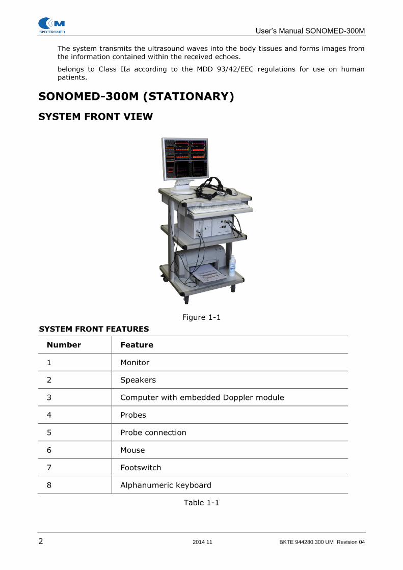
SONOMED-300M (STATIONARY)
SYSTEM FRONT VIEW
Figure 1-1
SYSTEM FRONT FEATURES
Number Feature
1 Monitor
2 Speakers
3 Computer with embedded Doppler module
4 Probes
5 Probe connection
6 Mouse
7 Footswitch
8 Alphanumeric keyboard
Table 1-1

User’s Manual SONOMED-300M
BKTE 944280.300 UM Revision 05 2015 04 3
SYSTEM REAR PANEL
Figure 1-2
SYSTEM REAR FEATURES
Number Feature
1 USB connection
2 Monitor connection
3 LPT connection
4 Footswitch connection
5 Keyboard connection
6 Mouse connection
7 Power cable connection
8 Power ON/OFF button
9 Speaker cable connection
Table 1-2

User’s Manual SONOMED-300M
4 2015 04 BKTE 944280.300 UM Revision 05
SONOMED-300M (PORTABLE)
SYSTEM FRONT VIEW
Figure 1-3
SYSTEM FRONT FEATURES
Number Feature
1 Computer
2 Probe connection
3 Power cable connection
4 Probe
5 Alphanumeric keyboard
Table 1-3
2
5
4
3
1

User’s Manual SONOMED-300M
BKTE 944280.300 UM Revision 05 2015 04 5
SONOMED-300M (USB BOX)
SYSTEM VIEW
FRONT PANEL
1 2 3
5 4
Figure 1-4
SYSTEM FRONT FEATURES
Number Feature
1 2 MHz Probe socket
2 4 MHz Probe socket
3 8 MHz Probe socket
4 Probes indicators
5 USB indicator
Table 1-4
REAR PANEL
2 1
Figure 1-5

User’s Manual SONOMED-300M
6 2015 04 BKTE 944280.300 UM Revision 05
SYSTEM REAR FEATURES
Number Feature
1 USB socket
2 Foot switch socket
Table 1-5

User’s Manual SONOMED-300M
BKTE 944280.300 UM Revision 05 2015 04 7
CHAPTER 2. SAFETY INFORMATION
NOTE: Read this information carefully before you begin operating the Sonomed-300M system.
ELECTRICAL SAFETY
According to IEC Standard 60601-1, Safety of Medical Electrical Equipment, the
Sonomed-300M system is classified as Class I, type BF.
NOTE: The use of ACCESSORY equipment not complying with the
equivalent safety requirements of this equipment may lead to a reduced level of safety of the resulting system. Consideration relating to the choice shall include:
Use of the accessory in the PATIENT VICINITY.
Evidence that the safety certification of the ACCESSORY
has been performed in accordance to the appropriate IEC601-1/IEC950 and/or IEC601-1-1 harmonized national standard.
Observe the following warnings for maximum safety.
WARNINGS: The system must be properly grounded to prevent shock hazards. Protection is provided by grounding the chassis with a
three wire cable and plug; the system must also be powered through a properly grounded receptacle.
Electrical shock hazard. Do not remove the system or the monitor cover. Refer servicing and internal adjustments to
qualified personnel only.
Do not replace the system fuses with types different from the ones specified by the manufacturer.
The equipment is not suitable for use in the presence of a flammable mixture with air, oxygen or nitrous oxide. Explosion
is a hazard under such conditions.
The system is not watertight and provides a class IP(X) 7 degree of protection to liquids; do not expose the system to
rain or moisture. Avoid placing liquid containers on the system.
Remove probes and electrocardiography leads from patient
contact before applying a high voltage defibrillation pulse.
Like any other ultrasound equipment, the Sonomed-300M
system uses high frequency signals which could interfere with
pacemakers. You should be aware of this small potential hazard and immediately turn off the unit if interference in the
pacemaker operation is noted or suspected.
If you drop or strike a probe, do not use it until a measure of the electrical leakage current has demonstrated that the

User’s Manual SONOMED-300M
8 2015 04 BKTE 944280.300 UM Revision 05
electrical safety has not been compromised.
Do not immerse the entire probe in liquids to clean it. The
probe is not watertight and immersion may compromise the electrical safety features of the probe.
Observe these precautions to prevent damage to your system.
CAUTIONS: To prevent further damage to your system and the accessories, power off the unit if it does not start up correctly.
Never expose the probes to gas, heat or liquid sterilization procedures. These methods can permanently damage the probe.
Carefully follow the User's Manual instructions to clean or disinfect a probe.
ENVIRONMENTAL SAFETY
ELECTRO-MAGNETIC COMPATIBILITY
Sonomed-300M system complies with the EN60601-1-2 Electro-Magnetic Compatibility.
It is a class A device.
To make full use of the system performance, install and use the equipment, following the
instructions in this manual.
CAUTIONS: Be sure to use optional items and accessories listed in this
manual. If not listed devices in this manual are used, the requirements of IEC60601-1-2 may not be satisfied. Keep the
length of the following cables that are to be connected to the main unit to 3m or shorter.
• USB cable
• LAN cable
Operation of the equipment may interfere with the operation of
other medical or nonmedical electrical equipment. Investigate the possibility of interference before use.
Keep the cables of the equipment (probe cable, I/O cable, etc) and the main unit well away from cables and main unit of other electrical equipment.
Be sure to use recommended optional equipment. Otherwise it may interfere with the equipment, and other electrical device
that are used in combination with the equipment.
Do not use radio devices such as mobile phones near medical electrical instruments such as this device. Otherwise a
malfunction may occur. Be sure to turn off the power of all the radio devices in a room where medical electrical equipment is
installed.

User’s Manual SONOMED-300M
BKTE 944280.300 UM Revision 05 2015 04 9
ENVIRONMENT CONDITIONS
REQUIREMENTS TO OPERATING:
Temperature: 10С to 40 С
Humidity (PH): 30 % to 85 %
Pressure: 700 hPa to 1060 hPa
REQUIREMENTS TO TRANSPORTATION
Temperature: -25C to +50C
Humidity (PH): Up to 98 % under +25ºC
Pressure: 700 hPa to 1060 hPa
REQUIREMENTS TO ALLOCATION AND INSTALLATION
Requirements to Mains Supply:
Sonomed-300M system must be connected to USB connection of the PC, which must be
connected to a separate mains supply socket designated for (100 – 240) V (50-60) Hz
AC.
Operating Conditions:
When installing the unit at the location of its regular operation, be sure that there is
enough space around the unit for ventilation.
Do not install the unit so that the monitor screen is exposed to direct sunlight. This may
deteriorate the visualization of the ultrasound image.
Interference:
The unit must be installed in premises with wooden, plastered, or concrete walls,
ceilings, and floors. This will diminish the impact of electromagnetic waves.
Do not install the unit close to an electric generator, X-ray equipment, a radio station, or
transmission lines as this may cause interference in the ultrasound image.
TRANSPORTING THE SYSTEM
The Sonomed-300M system is a TCD system, designed for use in a variety of settings.
Certain precautions should be taken when moving the system to reduce the risk of injury
and ensure reliable operation.
NOTE: It is especially important to protect the display screen of the system connected to the Sonomed-300M when transporting
the unit.
TRANSPORTING SONOMED-300M SYSTEM IN A VEHICLE
• Disconnect the probes and store them in a separate packing case.
• Place the system itself securely in a packing case or carrying case.
• Secure the case within the vehicle to prevent it from moving or shifting.
MOVING SONOMED-300M SYSTEM WITHIN A BUILDING
• Make sure that the probes are securely placed in the probes holder.
User’s Manual SONOMED-300M
10 2015 04 BKTE 944280.300 UM Revision 05
• Make sure that all cables are properly secured and that no cables are hanging loose.
ULTRASOUND SAFETY
The system complies with the requirements for the safety of ultrasonic medical diagnostic
and manufacturing equipment as established in European Directive 93/42/EEC and
international standards.
The Sonomed-300M is, therefore, equipped with the Acoustic Output Display feature to
provide the user with real-time, on-line information on the actual acoustic power of the
system.
ULTRASOUND BIOEFFECTS
According to the EN ISO 14971:2012 Medical devices – Application of risk management
to medical devices, the bio effects severity and occurrence have been analyzed to
determine their overall risks and to manage the reduction the risk levels as low as
possible.
Although diagnostic ultrasound has an excellent history of safety, it has been known for a
long time that ultrasound, at certain levels, can alter biological systems.
The relationship of various acoustic output parameters (for example, acoustic intensity,
pressure power, etc.) to biological endpoints is not presently fully understood. Evidence
to date has identified two fundamental mechanisms, thermal and mechanical, by which
ultrasound may induce bioeffects in certain cases alteration or damage to tissue.
The temperature rise and the possibility of cavitation seem to depend on such factors as
the total energy output, the mode, the shape of the ultrasound beam, the position of the
focus, the center frequency, the shape of the waveform, the frame rate, and the duty
factor. The TI and MI indices are designed to take all these factors into account and give
the user instant information about the potential for thermal or mechanical bioeffects.
Because the MI and TI indices reflect instantaneous output conditions, they do not take
into account the cumulative effects (especially heating) of the total examination time.
Thermal bioeffect is the rise in temperature of tissue when exposed to acoustic energy.
The acoustic energy is absorbed by body tissue; absorption is the conversion of this
energy into heat. If the rate of energy deposition in a particular region exceeds the
ability to dissipate the heat, the local temperature will rise. The rise in temperature will
depend on the amount of energy, the volume of exposure, and the thermal
characteristics of the tissue.
RISKS CONTROLS
ON-SCREEN REAL-TIME ACOUSTIC OUTPUT DISPLAY
Information is available through a new feature, named the Acoustic Output Display. The
Output Display provides users with information that can be specifically applied to ALARA.
This makes it possible for the user to get the best image possible while following the
ALARA principle and thus to maximize the benefits/risks ratio.
This Output Display Standard is intended to provide on-screen display of these two
indices, which are related to ultrasound thermal and cavitation mechanisms, to assist the
user in making informed risk (i.e. patient exposure) / benefit (diagnostically useful
information) decisions. Considering the type of exam, patient conditions and the case
study level of difficulty, the system operator decides how much acoustic output to apply
for obtaining diagnostically useful information for the patient; the thermal and
mechanical indices real-time display is intended to provide information to the system

User’s Manual SONOMED-300M
BKTE 944280.300 UM Revision 05 2015 04 11
operator throughout the examination so that exposure of the patient to ultrasound can
be reasonably minimized while maximizing diagnostic information.
THE MECHANICAL INDEX
As far as cavitation is concerned, there is agreement that the potential for biological
effects rises with a rising peak rare factional pressure. There is lesser agreement about
the frequency dependence of the occurrence of cavitation in tissue. Nevertheless, the
Mechanical Index (MI) is intended to give a relative indication of the potential for
mechanical bioeffects such as cavitation.
THE THERMAL INDEX
The Thermal Index(TI) gives a relative indication of the potential for temperature
increase at a specific point along the ultrasound beam. The reason for the term "relative"
is that the assumed conditions for heating in tissue are so complex that any single index
or model cannot be expected to give the actual increase in temperature for all possible
conditions and tissue types. There are currently two Thermal Indices (each based on a
specific Thermal Model) used to estimate temperature rise whether at the surface, within
the tissues, or at the point where the ultrasound is focusing on bone:
• The Cranial Bone Thermal Index provides information on temperature increase
within soft tissue, when the bone is located near the surface of the skin.
• The Soft Tissue Thermal Index provides information on temperature increase
within soft homogeneous tissue.
• The Bone Thermal Index provides information on temperature increase of bone
at or near the focus after the beam has passed through soft tissue
The modelling for predicting TI assumes some cooling by blood perfusion. For
applications where poorly perfused tissues are expected, the TI may underestimate the
possible worst-case temperature rise, and again the TI should be maintained at a lower
value. Conversely, when scanning organs known to be well perfused, such as vascular
structures, the value of TI may overestimate the temperature rise.
The Index values greater than 1 alert the operator to proceed with more caution, but if
values are less than 1 its need only for implementing the ALAPA principle.
If the Index value are below 0.5, its isn‟t need to be displayed.
User’s Manual SONOMED-300M
12 2015 04 BKTE 944280.300 UM Revision 05
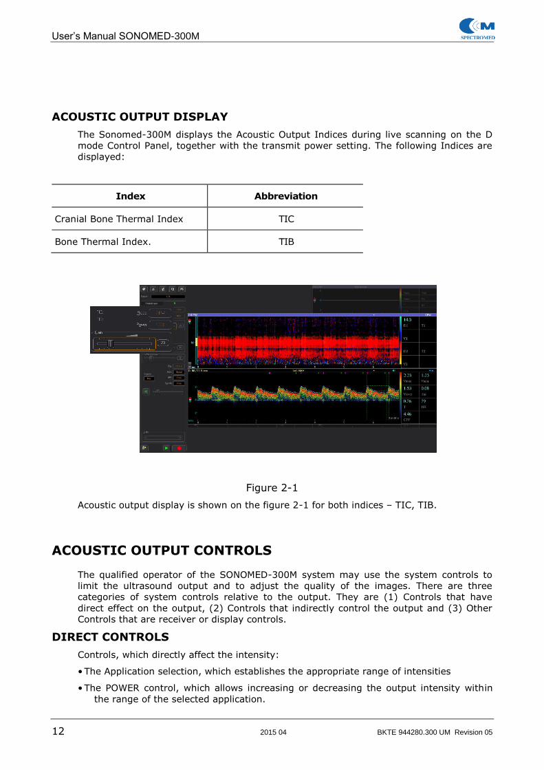
ACOUSTIC OUTPUT DISPLAY
The Sonomed-300M displays the Acoustic Output Indices during live scanning on the D
mode Control Panel, together with the transmit power setting. The following Indices are
displayed:
Index Abbreviation
Cranial Bone Thermal Index TIC
Bone Thermal Index. TIB
Figure 2-1
Acoustic output display is shown on the figure 2-1 for both indices – TIC, TIB.
ACOUSTIC OUTPUT CONTROLS
The qualified operator of the SONOMED-300M system may use the system controls to
limit the ultrasound output and to adjust the quality of the images. There are three
categories of system controls relative to the output. They are (1) Controls that have
direct effect on the output, (2) Controls that indirectly control the output and (3) Other
Controls that are receiver or display controls.
DIRECT CONTROLS
Controls, which directly affect the intensity:
• The Application selection, which establishes the appropriate range of intensities
• The POWER control, which allows increasing or decreasing the output intensity within
the range of the selected application.

User’s Manual SONOMED-300M
BKTE 944280.300 UM Revision 05 2015 04 13
INDIRECT CONTROLS
The controls that indirectly affect acoustic output are many imaging parameters. There
are operating mode and frequency range.
The operating mode determines whether ultrasound beam is scanning or non-scanning.
OTHER CONTROLS
The other controls (for example, gain, sweep speed, high pass filter, etc.) do not affect
ultrasound output. They should be used to adjust or adopt the Doppler signal image
together with controls that directly or indirectly affect output.
ALARA PRINCIPLE
Spectromed recommends the use of the ALARA (As Low As Reasonably Achievable)
principle (see below), which is extensively covered in this Manual.
The ALARA principle is the guideline for prudent use: during an exam, the user should
use for the shortest duration the least amount of acoustic output to obtain the necessary
clinical information for diagnostic purposes.
BIOCOMPATIBILITY
The Sonomed-300M system accessories that get in directly contact with the patient does
not cause allergic reactions or skin irritation and should be placed in contact only with
intact skin surface. No risk of damaging the cells or risks of potential irritation effects.

User’s Manual SONOMED-300M
14 2015 04 BKTE 944280.300 UM Revision 05
CHAPTER 3. GETTING STARTED
FUNCTION AND INTENDED USES
The Sonomed-300M ultrasound unit is intended for use as a diagnostic ultrasound
system:
• For the measurement of extra/intracranial or peripheral arteries blood velocities to
determine the presence of hemodynamically significant deviations from normal
values.
• For determination micro embolic signals (MES) in the arterial blood flow.
The Sonomed-300M is intended for use during:
• Diagnostic examinations
• Surgical manipulations
The device is not intended to replace other means of evaluating vital patient physiological
processes, is not intended to be used in fetal applications, and in not intended to be used
inside the sterile field.
The Sonomed-300M ultrasound unit is an advanced Transcranial Doppler (TCD)
ultrasound system that allow for non-invasive assessment of blood flow velocities
throughout the body. This method of measurement is particularly useful for examining
the major arteries supplying blood to the brain.
The Sonomed-300M is useful for evaluation of numerous neurological vascular problems
such as vasospasm and intracranial stenosis. The Sonomed-300M is also extremely
valuable for intraoperative monitoring to help with detection sudden changes in flow and
potential embolic events. Emboli are small particles of foreign matter (air, clots, etc.)
within the bloodstream that can potentially cause obstructions in various arteries in the
body and the brain. Such obstructions can often lead to stroke.
The Sonomed-300M may be used as for routine vascular examinations as in operating
rooms, intensive care units and emergency departments. The main TCD applications are
listed below:
• Detection and quantification of intra - extracranial stenoses/occlusions
• Detection of vasospasm due to subarachnoid hemorrhage
• Detection of arteriovenous malformations (AVMs)
• Evaluation of intracranial/vertebrobasilar circulations
• Assessment of collateral pathways
• Detection of Patent Foramen Ovale (PFO)
• Detection of embolic events
• Recording trends of blood flow parameters and indices
• Assistance during surgical manipulations and interventional procedures using
immediate feedback
• Implementation of different tests for functional diagnostic of the blood flow system
Intended Operator
The Sonomed-300M is intended for trained and skilled personnel to carry out Doppler
transcranial/peripheral examinations. Spectromed recommends that trained personnel
ONLY use these systems.

User’s Manual SONOMED-300M
BKTE 944280.300 UM Revision 05 2015 04 15
SYSTEM PREPARATION
The Sonomed-300M ultrasound unit must operate within the proper environment and in
accordance with the requirements. Before using the unit, ensure that all these
requirements are met.
SITE REQUIREMENTS
The following site requirements are necessary for the Sonomed-300M ultrasound unit to
function optimally:
POWER REQUIREMENTS
The Sonomed-300M ultrasound unit requires an appropriate power supply depending on
the version (stationary, portable or USB box).
OPERATING ENVIRONMENT
Ensure that there is sufficient airflow around the Sonomed-300M ultrasound unit.
WARNING: DO NOT install the unit in a location where the display screen is
exposed to direct light. Reflections on the screen make it difficult to view images.
ENVIRONMENTAL REQUIREMENTS
The operational environment of the Sonomed-300M ultrasound unit requires constant
maintenance. Different temperature and humidity ranges are specified for operation, storage
and transportation, and are shown in the table below:
Requirement Temperature Humidity Air Pressure
Operational 10 to 40°C 50-70% 700-1060 hPa
Storage -20 to 50° 10-95% 700-1060 hPa
Transport -20 to 50° 10-95% 700-1060 hPa
Table 3-1
ELECTROMAGNETIC INTERFERENCE
Ensure that the following criteria are met to protect the system from electromagnetic
interference:
Operate the unit at least 6 m away from equipment that emits strong electromagnetic
radiation.
Operate the unit in an area enclosed by walls, floors and ceilings comprised of wood,
plaster or concrete, which help prevent electromagnetic interference.
Shield the unit when operating it near radio broadcast equipment.
NOTE: Sonomed-300M TCD unit is approved for use in hospitals, clinics and other environmentally qualified facilities, in terms of the prevention of radio wave interference. Operation of the unit
in an inappropriate environment can cause electronic interference to radios and television sets situated near the
medical equipment.

User’s Manual SONOMED-300M
16 2015 04 BKTE 944280.300 UM Revision 05
TURNING SYSTEM ON/OFF
CAUTION: Verify the hospital supply voltage corresponds to the power supply voltage range.
To turn the system on/off:
Turn on the power button of the main PC unit. After loading OS the Sonomed-300M
software is loaded automatically. If you close the application you can run it again to
click the Sonomed-300M icon on the desktop of PC. Upon power up, the system
goes through its boot-up sequence.
NOTE: Never turn the system OFF when it is in the process of booting-up, as this may cause a fatal error. Always wait until
the software screen appears before turning the system OFF.
When the system is on, the unit undergoes an initialization sequence, which includes the
following steps:
• Loading of the operating system.
• Loading of the system software.
• Quick diagnostics of the unit.
The system goes through its shutdown sequence after power off.

User’s Manual SONOMED-300M
BKTE 944280.300 UM Revision 05 2015 04 17
CONNECTING AND REMOVING TRANSDUCERES
Insert the probe connector gently into one of the receptacles on the front panel of the unit. The probe connector is keyed to allow proper insertion. Turn the lock ring on the probe connector clockwise up to fixation (only for 4 and 8 MHz probes).
Do not force the probe connector into position. If you excessive resistance, remove the connector and try again.
When transporting the system in a vehicle or over any long distance, place the probe securely in a separate packing case.
See Chapter 7 Maintenance, Care and Service on page 7-2 for important information
on probe cleaning and infection control.

User’s Manual SONOMED-300M
18 2015 04 BKTE 944280.300 UM Revision 05
1 22
SYSTEM CONTROLS
SCREEN LAYOUT
Figure 3-1
SCREE LAYOUT FEATURES
Number Feature
1 Control Panel.
2
Image Windows: M-mode(Navigation) windows, D-
mode (Spectral) windows, T – trends window, S-signal window(both only during monitoring).
3 Soft Keys Toolbar.
4 Patient Header. Displays current patient surname.
5 Control panel with Tabs, which show the current state of the control elements for different windows(M, D, T, S)
of the TCD.
6 Blood flow parameters Tables. Displays calculated
parameters and indices of blood flow.
7 Soft Keys Status Bar.
Table 3-2
3
4
5
7
6

User’s Manual SONOMED-300M
BKTE 944280.300 UM Revision 05 2015 04 19
The Sonomed-300M ultrasound unit is operated through a control panel consisting of a
set of soft keys, a Trackball and alphanumeric keyboard or functional keyboard. The
buttons and controls are grouped in areas on the control panel according to their
functions.
The operator controls are used to perform several types of actions:
• Enter patient details.
• Perform an examination and apply different modes. Store static images or sequences (cineloops) for later analysis. Store reports containing patient
information.
• Adjust image quality parameters. Control the printer and other peripherals.
Perform measurements on the images.
CONTROL PANEL
All possible menu options are continuously displayed across the Control Panel. Menu
options are selected by moving the cursor to the desired cell and Left clicking it (the
cursor placed on the control element changes its form as follows). A pop-up menu with
different selections will automatically be displayed. To activate a selection, simply use the
Trackball or mouse to point it and Left click the desired selection.
The Sonomed-300M control panel consists of several sets of keys:
• Pre-examination buttons, such as Patient and Probe, those enable essential details to be entered and tools to be selected.
• Buttons that enable toggling between different modes, performing different
functions within a mode, and various other scan related functions such as reporting, recording, printing, and so on.
• A trackball, together with supplementary buttons that enable navigation around the screen.
• A functional keyboard can also be used to control TCD system.
• Soft keys, whose functions vary according to the current scan mode. The soft keys are grey and are located at the top of the control panel, near the
screen. They are not labeled. An identical set of corresponding soft keys is displayed on the screen. An icon is displayed to indicate the soft key's function in a particular mode and the function of the corresponding soft keys
on the control panel. For further information, refer to the Soft Keys section, page.
• Standard alphanumeric keyboard with designated function keys. The alphanumeric keyboard is used for entering patient information, and/or text annotations, on the screen. For further information, refer to the
Alphanumeric Keyboard section.

User’s Manual SONOMED-300M
20 2015 04 BKTE 944280.300 UM Revision 05
SOFT KEYS TOOLBAR
The soft keys are located at the top and bottom of the control panel and are not labeled.
An identical set of corresponding soft key icons is displayed on the screen for each mode.
A tip label below each soft key on the screen indicates its function (when the cursor is
placed on the key in a few seconds) and that of the soft key on the control panel in that
particular mode. The functions of the soft keys vary according to the mode and/or
module in which the user is working.
Soft key Description
Preset Control key. Displays a dialog box that enables
presets to be created, modified or restored to factory settings by the user.
Printer key. Prints a copy of the displayed image.
Settings key. Configure existing system functionality.
Additional Commands key.
Archive key. Saves all new data(one or a few spectra) into the current Archive.
Table 3-3

User’s Manual SONOMED-300M
BKTE 944280.300 UM Revision 05 2015 04 21
PRESET CONTROL
This tool saves user settings of the system and makes it possible to select which user
program shall be started when a new exam is created. Press the Preset Control key to
access and set up the following functions:
a) b)
Figure 3-2
Preset Controls Description
Preset List Displays the Preset List of the User Programs. The
details of the selected User Program are displayed in the Parameter, Value and Description
windows.
Load On start exam loads the user program selected from
the Preset List of all user programs: Figure 3-2 a).
To load a User Program:
1. Press the Preset Control key to access the
Preset Control on-screen menu.
2. From the list of Preset List select a desired
program, i.e extracranial or intracranial.
3. Press the Load key to confirm selection.
4. Press the Cancel key to exit.
Advanced This tool opens the Advanced options: Figure 3-2 b)
Add This tool saves the new settings of the Image Window with a new label.
To save a new User Program:
1. Press the Add key.
2. Enter a new program label and description using
a keyboard.
3. Press the OK key to confirm.

User’s Manual SONOMED-300M
22 2015 04 BKTE 944280.300 UM Revision 05
Preset Controls Description
Rewrite This tool rewrites a selected User Program with new settings.
Edit This tool saves current settings with a new label and description.
Delete This tool deletes a User Program.
Export This tool saves a User Program in a file with PRS extension.
Import This tool loads a User Programs in the system from a file. The user can restore settings that have become corrupted, as well as transfer user-modified and user-
created presets from one user group to another, or from one machine to another.
SETTINGS
Settings are used to customize the system. Press the Settings key to access and set up
the following system functions:
Figure 3-3
System functions Description
Layout Configure display for user defined number and
arrangement of image windows.

User’s Manual SONOMED-300M
BKTE 944280.300 UM Revision 05 2015 04 23
System functions Description
Indexes Configure system for user defined
measurements.
Print Configure printer settings:
• Printer type.
• Image scale.
• Alignment.
Commands Configure system functions:
• Save Settings:
• To save visible on the screen image only.
• To save visible image with content of memory buffer.
• Start/Stop key Settings:
• Pressing the Start/Stop key automatically opens the Archive Tab.
• Activation of the Image Window automatically opens the D Mode Tab.
Hardware settings Configure hardware settings:
• Sound card output.
• To adjust a sound card.
• To coordinate a spectrum with blood flow direction.
• To connect Foot Switch and Functional Keyboard.
About system Displays system hardware and software versions.
Table 3-4
Layout Setup
The system has advanced image optimization technology that greatly simplifies user
controls. It is also important to select an optimization setting that best matches your
needs.
To achieve the best possible diagnosis quality, it is important to properly adjust the
screen layout to enable toggling between side-by-side and top-bottom layouts when
viewing two modes in parallel.
To set up the number and arrangement of the Image Windows, follow these steps:
Press the Settings key to open the Settings on-screen menu.
Select the Layout item in the Settings on-screen menu.

User’s Manual SONOMED-300M
24 2015 04 BKTE 944280.300 UM Revision 05
Select the desired number and arrangement settings by opening the corresponding M+D
Mode Tab, M+DD Mode Tab or TCD Monitoring Mode Tab.
Indexes
Figure 3-4
Printer
Figure 3-5

User’s Manual SONOMED-300M
BKTE 944280.300 UM Revision 05 2015 04 25
System functions Description
Print type Select the desired printer type by clicking the
Color or Monochrome check box.
Scale Select the desired scale by clicking one of the
following check boxes:
• Small
• Normal
• Middle
• Large
Shift Set the desired Left and Top margins.
Not print CFM window In Not print CFM window, click the check box to restrict printing the window or leave unchecked to allow.
Table 3-5
COMMANDS
Figure 3-6
System functions Description
Store Select the desired storage type by clicking the One screen or Full data buffer check box.
Save CFM data In Save CFM data window, click the check box to allow saving the data or leave unchecked to
restrict.
Cycle view In Cycle view window, click the check box to

User’s Manual SONOMED-300M
26 2015 04 BKTE 944280.300 UM Revision 05
System functions Description
allow cycling view or leave unchecked to restrict.
Remember windows type in layout
In Remember windows type in layout window, click the check box to allow
remembering the data or leave unchecked to restrict.
Auto bookmark mode change
In Auto bookmark mode change window, click the check box to allow auto bookmarking
or leave unchecked to restrict.
Table 3-6
HARDWARE
About program
Figure 3-7
System functions Description
Device Type Displays information about the following hardware modules:
• Doppler
• Digital Doppler
• TCD Monitoring
• A Scanner
The details of the selected module are
displayed in the Parameter and Value windows.
Table 3-7

User’s Manual SONOMED-300M
BKTE 944280.300 UM Revision 05 2015 04 27
SOFT KEYS STATUS BAR
Exit and Turn Off key. Used to exit from any of the applications.
Play/Stop key in the Stop Mode.
Start/Stop key. Used to freeze images in all modes for analysis and for storing for future use.
IMAGE WINDOW CONTROLS
The Sonomed-300M ultrasound system enables the user to split the screen into several
windows, so that exam results can be compared:
The active window is marked with a brighter window frame. Non-active windows are
marked with a hollow frame.
The size of the active window can increased using the F5 key.
The image controls apply only to the active window. When the system is in Start/Stop
Mode, the user can toggle between windows, and modify the selected window without
affecting the settings of the non-active windows.
A cursor is available in the setup of the active window. The cursor allows interaction to
occur using the Trackball and the mouse keys.

User’s Manual SONOMED-300M
28 2015 04 BKTE 944280.300 UM Revision 05
D MODE TAB CONTROLS
Figure 3-8
Controls/Keys Icon/Menu Description
Probe
Left click the field to select the Probe. There are 3 probes
(2/4/8 MHz), which are working in PW – pulse waves mode or CW – continuous wave mode.

User’s Manual SONOMED-300M
BKTE 944280.300 UM Revision 05 2015 04 29
Controls/Keys Icon/Menu Description
Power
Controls the radiated acoustic power by changing the amplitude
of the TX ultrasound signals. Left click the field to select the desired
Power level.
Gain
Slide the Gain bar to the right to increase or left to decrease the amount of gain applied to the
overall image.
Doppler Window
Properties
Opens the Doppler window
Properties on-screen menu.
Right click on the Doppler
Window to open on-screen menu and select the Properties option.
Pressure measurement
Opens Pressure measurement on-screen menu.
Velocity Scale
Left click the BW(Band Width)
field to adjust the blood flow Velocity Scale. Depending on the Scale Units of the flow
velocity, on-screen menu units will be in KHz or cm/s.
Sweep Rate
Left click the Rate field to select the desired sweep rate scale from
the on-screen menu.
High Pass Filter
Left click the High Pass Filter
field to select the desired cut off frequency from the on-screen menu.
Smooth
Left click the Smooth field to select the level of smoothing
which enables radial and lateral smoothing of the color pixels.
Audio Signal
Slide the Loudness bar to the right to increase or left to decrease the sound volume
derived from the PW spectrum.

User’s Manual SONOMED-300M
30 2015 04 BKTE 944280.300 UM Revision 05
Controls/Keys Icon/Menu Description
Cine
On a frozen image, shows individual frames in the Cine
Buffer.
Table 3-8
D MODE WINDOW SETUP
Figure 3-9
Number Description
1 Probe.
To change the Probe:
On the D Mode Control Panel Left click the Probe field to open the drop down menu.
Highlight the desired Probe and Left click to select.
2 Flow Velocity Scale.
At the left side of the window the Flow Velocity Scale with maximum values (in relation the zero line) and the selected
measuring unit are displayed.
To adjust the Flow Velocity Scale:
On the D Mode Control Panel Left click the Band Width(BW) field to open the drop down menu.
Highlight the desired BW and Left click to adjust.
3 Flow Direction Indicator
To change the direction of the Flow Direction Indicator:
Place the cursor on the Flow Direction Indicator.
Left click to toggle the direction.
1 4 9 10 6 2 3 5 7 8

User’s Manual SONOMED-300M
BKTE 944280.300 UM Revision 05 2015 04 31
Number Description
4 Vessel Label
5 Flow Velocity Scale Unit
To change the Scale unit:
- Place the cursor on to the vertical scale axis(Flow Velocity Scale) and double click Right button.
- Open the Properties on-screen menu (see instruction below).
In the Velocity Scale box press the required key to toggle the scale.
6 Zero Baseline
To change the position of the Zero Baseline:
Place the cursor on to the vertical scale axis(Flow Velocity Scale) and Left click to change the Zero Baseline.
7 Sweep Rate Scale
To adjust the Sweep Rate Scale:
On the D Mode Control Panel Left click the Rate field to open the drop down menu. Highlight the desired sweep rate scale and Left click to adjust.
8 Color Map
Direction and velocity are colored-coded in two-color scale:
• Flow toward the probe – Red.
• Flow away from probe – Blue.
Low flow is displayed by dark red or dark blue (depending on the direction). With increasing velocity the color changes from dark red to yellow respectively from dark blue to white
(depending on the direction).
To change the Color Map:
Place the cursor on the Color Map.
Left click to toggle between the available color maps.
Or
Open the Properties on-screen menu (see instruction below).
Select the down-arrow to the right of the Palette field to open
the drop down menu.
Highlight the desired Color Map and Left click to adjust.
9 Sound Indicator.
Indicates, which D Mode Window is active.
10 Doppler Parameter Box

User’s Manual SONOMED-300M
32 2015 04 BKTE 944280.300 UM Revision 05
Table 3-9
To adjust D Mode Window settings, follow these steps:
Place the cursor on the D Mode Window and Left click to activate.
Right click on the active D Mode Window to open on-screen menu.
Highlight and Left click the Properties item to open the Properties on-screen menu.
Select the Indexes Tab to open the following on-screen menu:
Figure 3-10
Set up the required parameters.
Press the OK key to apply settings.
Press the Set Default key to return to the factory settings.
Press the Cancel key to exit.
System functions Description
View box:
Spectrum Enable the check box to show the spectrum.
Maximum Velocity Enable the check box to show the Maximum Velocity Curve.
Velocity Scale box:
kHz or cm/s Blood flow velocity scale unit setup.
Angle CW Setup of the angle between Probe axis and
blood flow direction in the CW Mode.
Angle PW Setup of the angle between Probe axis and
blood flow direction in the PW Mode.

User’s Manual SONOMED-300M
BKTE 944280.300 UM Revision 05 2015 04 33
System functions Description
Palette Select the down-arrow to the right of the
Palette field to open the dropdown menu to select the desired Color Map.
Set default To return settings for this setup page to factory default, select Set default key from the on-screen menu.
OK Confirms settings
Cancel Cancels settings.
Table 3-10

User’s Manual SONOMED-300M
34 2015 04 BKTE 944280.300 UM Revision 05
M MODE TAB CONTROLS
Figure 3-11
Controls/Keys Icon/Menu Description
Probe
Left click the field to select the
Probe. There are 3 probes (2/4/8 MHz), which are working
in PW – pulse waves mode or CW – continuous wave mode.
Power
Controls the radiated acoustic
power by changing the amplitude of the TX ultrasound signals. Left
click the field to select the desired Power level.

User’s Manual SONOMED-300M
BKTE 944280.300 UM Revision 05 2015 04 35
Controls/Keys Icon/Menu Description
Gain
Slide the Gain bar to the right to increase or left to decrease the
amount of gain applied to the overall image.
Turbulence Threshold
Slide the Turbulence Threshold bar to select the required level.
The current selection is displayed in the window.
Power Threshold
Slide the Power Threshold bar to select the required level. The
current selection is displayed in the window.
Doppler Window Properties
Opens the Doppler window Properties on-screen menu.
Or
Right click on the Doppler Window to open on-screen menu
and select the Properties option.
Pressure
measurement
Opens Pressure measurement
on-screen menu.
Band Width
Left click the field BW to adjust the Velocity Range. Depending on
the Scale Units of the flow velocity scale, on-screen menu
units will be in KHz or cm/s.
Sweep Rate
Left click the field Rate to select the desired sweep rate scale from the on-screen menu.
HPF
Left click the High Pass Filter field to select the desired cut off
frequency from the on-screen menu
Smooth
Left click the Smooth field to select the level of smoothing which enables spectrum
smoothing and removing some noises.

User’s Manual SONOMED-300M
36 2015 04 BKTE 944280.300 UM Revision 05
Controls/Keys Icon/Menu Description
Gamma
Left click the Gamma field to select the required level of the M-
mode brightness.
Audio Signal
Slide the Loudness bar to the
right to increase or left to decrease the sound volume of the
Doppler signal.
Cine
On a frozen image, shows
individual frames in the Cine Buffer.
Table 3-11

User’s Manual SONOMED-300M
BKTE 944280.300 UM Revision 05 2015 04 37
M MODE WINDOW SETUP
Figure 3-12
Number Description
1 Probe.
To change the Probe:
On the D Mode Control Panel Left click the Probe field to open the drop down menu.
Highlight the desired Probe and Left click to select.
2 Flow Direction Indicator
To change the direction of the Flow Direction Indicator:
Place the cursor on the Flow Direction Indicator.
Left click to toggle the direction.
3 SV Depth Scale.
To adjust the SV Depth:
Place the cursor on the SV gate.
Left click and keep pressing, move the SV gate to the required
depth. The current depth (54 mm) is displayed in the low left corner of the screen: D 54/13.1 mm.
4 SV gate size
To adjust the SV gate size:
Place the cursor on the SV gate.
Right click and keep pressing, move the cursor up or down to select the required size. The current SV Size (13.1 mm) is
displayed in the low left corner of the screen: D 54/13.1 mm.
1 4
12
7
10
2 3
8 11
6 5
9 13

User’s Manual SONOMED-300M
38 2015 04 BKTE 944280.300 UM Revision 05
Number Description
5 Color Map
To change the Color Map:
Place the cursor on the Color Map.
Left click to toggle between the available color maps.
6 Parameters box
7 Mode Indicator
To select the mode:
Left click the Mode Indicator to open the drop dawn menu.
Highlight the CFM Mode or PD Mode and Left click to select.
8 SV Depth and SV Size current value.
9 Depth Scrollbar
Use the up or down arrow to adjust the Depth Scale.
10 Vessel Label
11 Sweep Rate Scale
To adjust the Sweep Rate Scale:
On the D Mode Control Panel Left click the Rate field to open the drop down menu.
Highlight the desired sweep rate scale and Left click to adjust.
12 Sound Indicator
Indicates, which D Mode Window is active when M+DD
Mode layout is selected.
13 Connectivity Indicator
Indicates the connection between M and D Windows (in M+D or MDD Modes.
Table 3-12

User’s Manual SONOMED-300M
BKTE 944280.300 UM Revision 05 2015 04 39
BASE TAB
Images are saved to the system hard disk. The images in the Patient List are organized
alphabetically by the patient name or in some other order.
The number of images saved to the hard disk varies depending on the storage capacity of
the disk.
Figure 3-13
Controls/Keys Icon/Menu Description
Patient List
Press the Patient List key to open the Patients on-screen menu.
New Patient
Press the New Patient key to open the New Patient form.

User’s Manual SONOMED-300M
40 2015 04 BKTE 944280.300 UM Revision 05
Controls/Keys Icon/Menu Description
Main Menu
Press the Main Menu key to open the drop dawn menu.
Archive Settings
Press the Archive Settings key
to open the Archive Settings on-screen menu.
New Report
Press the New Report key to open the Examination Report.
Doctor Name Doctor Name field
Examinations
Examinations Widow displays the list of examinations for the currently selected patient.
Results/Reports
Press the Renaults/Reports key to compose a report for the
currently selected examination result.
Results
Results Widow displays the list
of examination results for the currently selected patient.
Result Image
Result Image Window displays the image for the currently
selected examination result.
Table 3-13
SETUP OF THE BASE TAB
The Archive tab enables the user to set general parameters related to the Archive
function, including:
• Patient
• Connect to database
• Doctors and Groups
• Hospital
• Address Book
• Service
PATIENT
To setup the Patient parameters, follow these steps:

User’s Manual SONOMED-300M
BKTE 944280.300 UM Revision 05 2015 04 41
Select the Archive Tab.
Press the Main Menu key to open the drop down menu.
Figure 3-14
Select the Patient field to open the dropdown menu.
Select the Edit field.
Use the Alphanumeric Keyboard to enter the patient's details or last name in the Search
enter field. Use the Backspace key or Delete key to correct mistakes.
CONNECT TO DATABASE
To setup the Connect to Database parameters, follow these steps:
Select the Archive Tab.
Press the Main Menu key to open the drop down menu.
Select the Connect to Database field to open the Connect to Database (Connect to
archive) dialog box.
Figure 3-15
Press the Create New Archive key to open the New Doctor dialog box.
Figure 3-16
Use the Alphanumeric Keyboard to enter the doctor's details. Use the Backspace key or
Delete key to correct mistakes and press the OK key to confirm.
To open the Existing Database, follow these steps:
Select the Archive Tab.

User’s Manual SONOMED-300M
42 2015 04 BKTE 944280.300 UM Revision 05
Press the Main Menu key to open the drop down menu.
Figure 3-17
Select the Connect to Database field to open the Connect to Database (Connect to
archive) dialog box.
Press the Open Existing Database key to open the Open dialog box.
Select the desired Database and press the OK key to confirm.
To setup the Database Settings, follow these steps:
Select the Archive Tab.
Press the Main Menu key to open the drop dawn menu.
Select the Connect to Database field to open the Connect to Database (Connect to
archive) dialog box.
Press the Database Settings key to open the Database Settings dialog box.
Figure 3-18
On the Directories tab press the Choose Directory key to to open the Browse for
Folder dialog box.
Select the directory and press the OK key to confirm or Cancel to exit. The current
directory is displayed in the Current Database Directory field.
To export the Database, press the Choose Directory key to to open the Browse for
Folder dialog box.
Select the directory to export and press the OK key to confirm or Cancel to exit. The
current directory is displayed in the Export Directory field.
To import the Database, press the Choose Directory key to to open the Browse for
Folder dialog box.
Select the directory to import and press the OK key to confirm or Cancel to exit. The
current directory is displayed in the Import Directory field.
DOCTORS AND GROUPS

User’s Manual SONOMED-300M
BKTE 944280.300 UM Revision 05 2015 04 43
To setup the Doctor and Groups parameters, follow these steps:
Select the Archive Tab.
Press the Main Menu key to open the drop dawn menu.
Figure 3-19
Highlight the Doctor and Groups item to open the New Doctor on screen menu.
Figure 3-20
Use the Alphanumeric Keyboard to enter the doctor's details.
Press the OK key to confirm or Cancel key to turn off the text entry and exit.
HOSPITAL
To setup the Hospital parameters, follow these steps:
Select the Archive Tab.
Press the Main Menu key to open the drop dawn menu.
Figure 3-21
Highlight the Hospital item to open the New Doctor on screen menu.
Figure 3-22
Use the Alphanumeric Keyboard to enter the hospital's details.
Press the OK key to confirm or Cancel key to turn off the text entry and exit.
ADDRESS BOOK
To setup the Address Book, follow these steps:

User’s Manual SONOMED-300M
44 2015 04 BKTE 944280.300 UM Revision 05
Select the Archive Tab.
Press the Main Menu key to open the drop down menu.
Figure 3-23
Highlight the Address Book item to open the Address Book on screen menu.
Figure 3-24
Press the Add key to open the Organization dialog box.
Figure 3-25
Use the Alphanumeric Keyboard to enter the organization's details.
Press the OK key to confirm Cancel key to turn off text entry and exit.
To edit the Address Book entry, follow these steps:
Highlight the organization to be edited in the Organization List box of the Address
Book on screen menu.
Press the Show key to open the Organization dialog box.
Use the Alphanumeric Keyboard to edit the organization's details.
Press the OK key to confirm or Cancel key to turn off the text entry and exit.
To delete the Address Book entry, follow these steps:
Highlight the organization to be deleted in the Organization List box of the Address
Book on screen menu.
Press the Delete key to delete the organization.
SERVICE

User’s Manual SONOMED-300M
BKTE 944280.300 UM Revision 05 2015 04 45
The Service settings enable the user to set parameters related to the Archive function,
including:
• Export
• Import
• Examination Glossary
• Report Templates
• Address Book
• Technology Map
To setup the Service parameters, follow these steps:
Select the Archive Tab.
Press the Main Menu key to open the drop down menu.
Figure 3-26
Highlight the Service item to open the drop down menu.
Figure 3-27
EXPORT
To export the Service parameters, follow these steps:
Highlight the Export item in the Service drop down menu.
IMPORT
To import the Service parameters, follow these steps:
Highlight the Import item in the Service drop down menu.
EXAMINATION GLOSSARY
To setup the Examination Glossary parameters, follow these steps:
Highlight the Examination Glossary item in the Service drop down menu.
Figure 3-28
Left click the Examination Glossary item or press the Enter key to open the
Examination Glossary dialog box.

User’s Manual SONOMED-300M
46 2015 04 BKTE 944280.300 UM Revision 05
Figure 3-29
To enable an item or sub item in the Glossary box, using the scroll bar, select them and
check in.
In the Template Content box description of the selected glossary item is displayed.
To disable an item or sub item in the Glossary box, using the scroll bar, select them and
check off.
To delete an item or sub item in the Glossary box, press the Delete key to open the
Database dialog box.
Press the OK key to confirm deleting or Cancel to exit.
Figure 3-30
To edit the Examination Glossary item, follow these steps:
Highlight the Examination Glossary item in the Service drop down menu and left click
it or press the Enter key to open the Examination Glossary dialog box.
Press the Edit key to open the edit options.
Figure 3-31

User’s Manual SONOMED-300M
BKTE 944280.300 UM Revision 05 2015 04 47
Fill the Examination Area field and press the Add key.
Fill the Organ field and press the Add key.
Fill the Template field and press the Add key.
To hide the edit options, press the Hide key.
REPORT TEMPLATES
To setup the Report Templates parameters, follow these steps:
Highlight the Report Templates-Conclusions item in the Service drop down menu.
Figure 3-32
Left click the Report Templates-Conclusions item or press the Enter key to open the
Report Conclusion dialog box.
Figure 3-33
Press the New key to open the Template dialog box and fill the Name field.
Figure 3-34
Press the OK key to confirm or Cancel to exit.
Use the Alphanumeric Keyboard to enter the conclusion's text. Use the Backspace key
or Delete key to correct mistakes and press the Save key to confirm.
Press the Cancel key to exit.

User’s Manual SONOMED-300M
48 2015 04 BKTE 944280.300 UM Revision 05
TECHNOLOGY MAP
To setup the Technology Map parameters, follow these steps:
Highlight the Technology Map item in the Service drop down menu.
Figure 3-35
Left click the Technology Map item or press the Enter key to open the Technology
Map dialog box.
Figure 3-36
Select the desired parameters by selecting options from drop down menus, filling the fields and enable/disable check boxes.
Press the OK key to confirm deleting or Cancel to exit.
ENTERING HOSPITAL, DOCTOR AND PATIENT DETAILS
ENTERING HOSPITAL NAME
If this is the first time the SM-300 unit is turned on, the dialog box for entering the
hospital details appears on the screen.
The contents of the Hospital field are displayed in the title bar of the screen in every scan
mode. The remaining fields may appear on printed reports.

User’s Manual SONOMED-300M
BKTE 944280.300 UM Revision 05 2015 04 49
Use the Alphanumeric Keyboard to enter the hospital's details. Use the Backspace key or
Delete key to correct mistakes.
Figure 3-37
To enter the hospital name, follow these steps:
Turn the system on to open the Hospital Name on-screen menu.
Use the Alphanumeric Keyboard to enter, delete, or modify text in the fields.
Press the Backspace key to delete characters to the left of the cursor.
Press the Space key to add spaces between words or replace characters with blank spaces to the right of the cursor.
Press the Arrow keys to move the cursor to the left or right.
Press the Enter key to return the cursor to the beginning of the line of
text.
Press the Delete key to delete characters to the right of the cursor.
Press the OK key to confirm.
Press the Cancel key to turn off text entry.
LOGGING ON TO THE SYSTEM
Doctor and Patient information can be stored in the database, and retrieved when the
patient comes in for subsequent examinations. Doctor and Patient information can be
entered either by defining a new patient, or by retrieving the details of an existing
patient from the database.
If a patient has previously been examined or entered into the database, the Archive Tab
must be activated in order to retrieve his data.
Logging on as part of a group enables user-specific and user-defined settings and presets
to be used. Each time you turn the system on, the following Doctors and Groups on-
screen menu appears on the screen:

User’s Manual SONOMED-300M
50 2015 04 BKTE 944280.300 UM Revision 05
Figure 3-38
To retrieve doctor information, follow these steps:
Start up the Sonomed-300M to open the Doctors and Groups on screen menu.
Highlight a doctor name and press the Select key to start the live imaging.
To add the new doctor or group name, follow these steps:
Start up the Sonomed-300M unit to open the Doctors and Groups on screen menu.
Press the Add key to open the Doctor/Group dialog box.
Highlight the Doctor item to open the New Doctor on screen menu.
Figure 3-39
Use the Alphanumeric Keyboard to enter the doctor's details.
Press the OK key to confirm.
Press the Cancel key to turn off text entry.
To add the new group name, follow these steps:
Start up the Sonomed-300M unit to open the Doctors and Groups on screen menu.
Press the Add key to open the Doctor/Group dialog box.
Highlight the Group item to open the New Group on screen menu.
Figure 3-40
Use the Alphanumeric Keyboard to enter the group name.
Press the OK key to confirm.
Press the Cancel key to turn off text entry.
To restore the deleted Doctor details, follow these steps:

User’s Manual SONOMED-300M
BKTE 944280.300 UM Revision 05 2015 04 51
Start up the Sonomed-300M unit to open the Doctors and Groups on screen menu.
Press the Restore key to open the Restore a Doctor dialog box.
Figure 3-41
In the Deleted Doctors Window select a required doctor name.
Press the Restore key to confirm.
Press the Cancel key to turn off restore procedure.
To edit the Doctor details, follow these steps:
Start up the Sonomed-300M unit to open the Doctors and Groups on screen menu.
Press the Edit key to open the Edit a Doctor dialog box.
Figure 3-42
Use the Alphanumeric Keyboard to edit the doctor details.
Press the OK key to confirm.
Press the Cancel key to turn off text entry.
To retrieve the details of an existing patient, follow these steps:
Select the Archive Tab.
Press the List of Patients key to open the Patients on-screen menu.
Select the Doctor and/or Group Filter.
Select the Search Parameter field.
Use the Alphanumeric Keyboard to enter the patient's details or last name in the Search
enter field. Use the Backspace key or Delete key to correct mistakes.
The Patients table will automatically display the patient's personal details according to
the entered parameters. Once a patient is entered, all saved images will be linked to that
patient.

User’s Manual SONOMED-300M
52 2015 04 BKTE 944280.300 UM Revision 05
Figure 3-43
PATIENTS SCREEN LAYOUT FEATURES
Number Feature
1 Select key
2 New Patient key. Opens a New Patient Form
3 Edit key. During an exam, the user can access the current patient's information and change it, as required.
4 Delete key
5 Exit key
6 Drop down list of Doctor Filter
7 Drop down list of Group Filter
8 Patients table
9 Comments entry box
10 Data Set Up key
11 Expanded Search key
12 Search enter field
13 Search Parameter selection field
Table 3-14
1 2 3 4 5
6 7
8
9
10
11
12
13

User’s Manual SONOMED-300M
BKTE 944280.300 UM Revision 05 2015 04 53
To use Expanded Search mode of an existing patient, follow these steps:
Select the Archive Tab.
Press the of Patients key to open the Patients on-screen menu.
Press Expanded Search key to open the Expanded on-screen menu.
Define the Expanded Search Parameters:
Registration Date check box
Birthdate check box
Age check box
Gender check box
Preliminary Diagnosis check box
Use the Alphanumeric Keyboard to enter the patient's details in the Search enter
field. Use the Backspace key or Delete key to correct mistakes.
Press the Search key to start the search. The Patients table will automatically display
the patient's personal details according to the entered parameters.
Using the Trackball, Left click the desired patient surname to highlight it.
Press the Select key or double left click the highlighted patient surname.
To delete Expanded Search Parameters, press the Cancel key.
Figure 3-44
1
2
3
4

User’s Manual SONOMED-300M
54 2015 04 BKTE 944280.300 UM Revision 05
EXPANDED SEARCH PATIENTS SCREEN LAYOUT FEATURES
Number Feature
1 Expanded Search Parameters check boxes
2 Search enter fields
3 Search key
4 Clear key
Table 3-15
NEW PATIENT REGISTRATION PROCEDURE
The patient information form allows information to be entered into the system for the
patient exam. Information which can be entered includes patient demographics, exam
information, and clinical information. This information is automatically placed on the page
of the patient report. Once a patient is entered, all saved images will be linked to that
patient.
To register a new patient, follow these steps:
Select the Archive Tab.
Press the Patients key to open the Patients on-screen menu.
Press the New Patient key to open a New Patient Form.
Use the Alphanumeric Keyboard to enter the patient's details in the New Patient Form.
The Surname field is obligatory. All other patient details are optional. Use the Backspace
key or Delete key to correct mistakes.
Press the Group key to open the Group Form.
Press the Group key to edit the List of Groups.
Press the Address Book key to select the patient‟s organization.
Press the OK key to register the inputs.
NEW PATIENT FORM

User’s Manual SONOMED-300M
BKTE 944280.300 UM Revision 05 2015 04 55
Figure 3-45
Number Feature
1 Address Book key
2 Group key. Opens the Group Form.
3 Close key. Closes the Group Form
4 Group Dialog Box key
5 List of Groups (Group Form is closed? Group Form is opened)
Table 3-16
D MODE WINDOW
Figure 3-46
1 2 3 4
5 6 7 8

User’s Manual SONOMED-300M
56 2015 04 BKTE 944280.300 UM Revision 05
D MODE LAYOUT FEATURES
Number Feature
1 Current Probe
2 Vessel Label
3 Change Indicator
4 Sound Indicator
5 Blood Flow Direction indicator
6 Zero Baseline. Enables the Doppler Spectrum to be shifted up and down.
7 Color Bar. The Color Bar displays velocity in cm/s.
8 Index Table
Table 3-17
D MODE WINDOW CONTROLS
Spectral Color Palette
This function allows to select different maps for color-coding of the blood flow spectrum.
It can be useful during expert analysis of a long monitoring records or usual routine
examinations and so on.
The color scale is used for evaluation of the Doppler signal intensity and distribution of
the velocities in the flow. The more red blood cells are moving with particular velocity
the higher color from scale is used to draw this point on the spectral line. So dark blue
color shows small part of the blood flow and bright red – main part of it.
To adjust the Spectral Color Palette, follow these steps:
Place the cursor on the Color Bar.
Left click repeatedly to select the desired color map.
Velocity scale
At the left side of the window the Velocity Scale with maximum values (in relation the
zero line) and the selected measuring unit are displayed.
To select the measuring unit of the Velocity Scale, follow these steps:
Place the cursor on the left part of the window.
Double left click to toggle between the measuring units: kHz or cm/s.

User’s Manual SONOMED-300M
BKTE 944280.300 UM Revision 05 2015 04 57
M MODE WINDOW
Figure 3-47
M MODE LAYOUT FEATURES
Number Feature
1 Sample Volume
2 Depth Scale
3 Depth Scale Shift
4 Sample Volume Depth
5 Sample Volume Size
6 Sound Indicator
7 Group Function Indicator
Table 3-18
MODE MANAGEMENT
Spectromed provides a comprehensive set of tools on the Sonomed-300M system that
allows its customers to meet the applicable mode of observation. The system has various
configurations and options. All are described in this user guide and may not apply to your
system. System features are dependent on your configuration, transducer, and exam
type.
There are following modes available:
D Mode Doppler imaging includes a spectrum analysis which describes the
Doppler shift signal from the moving reflectors within a Sample
Volume.
M+D Mode This imaging mode provides information about distribution of blood
flow velocity depending on depth (M Mode) in one window and D Mode
image in another one.
M+DD Mode It‟s a combination of M Mode window and two D Mode windows which
include spectrum analysis‟s within two Sample Volumes from different
Depths.
1
2
3
4
5 6 7

User’s Manual SONOMED-300M
58 2015 04 BKTE 944280.300 UM Revision 05
To select a mode, follow these steps:
Place the cursor over the active window and Right click to activate the Setup Menu.
Place the cursor over the Mode field and Left click to open the Exam Mode on-screen
menu with setup options.
Figure 3-48
In the Exam Mode on-screen menu, select the desired check boxes to set the settings.
Figure 3-49

User’s Manual SONOMED-300M
BKTE 944280.300 UM Revision 05 2015 04 59
EXAM TYPE SETUP
Exam type setup is used to customize the system. Press the Setup key to access
available options and set up the following system functions:
To select a vessel to be observed, follow these steps:
Left click the Image Window to activate it.
Place the cursor over the active window and Left click the Vessel Label field.
In the Vessel list, Left click the desired options.
Press the Select key to confirm. The optimal parameters will be automatically setup for
selected exam type.
Figure 3-50
System functions Description
1 Current vessel exam data
2 List of vessels and controls
Select Select key
Close Close key
Editor Editor key.
3 Close menu on selection a vessel (s) check box
4 Editor controls
Add Add key
Rename Rename key
1
2
3
4
5

User’s Manual SONOMED-300M
60 2015 04 BKTE 944280.300 UM Revision 05
System functions Description
Delete Delete key
Save Save key
5 Vessel (s) parameters controls
Get from the active window
Print Print key
Show Show key
Figure 3-51

User’s Manual SONOMED-300M
BKTE 944280.300 UM Revision 05 2015 04 61
CHAPTER 4. TCD EXAMINATIONS
BACKGROUND AND PURPOSE
Transcranial Doppler has been shown to be effective in every day examinations to
evaluate velocity changes in cerebral circulation post cerebral aneurysm rupture or
neuro-radiologic intervention as an equivalent means of practicing selective shunting
compared with other modalities, namely, EEG monitoring. TCD examination provides a
noninvasive, low-risk assessment tool that can be done at the bedside.
TCD is primarily a technique for measuring main parameters of the flow. The utility of the
technique is now well established for a number of different disease processes.
The doctor can best utilize TCD examination when baseline cerebral blood flow velocities
can be obtained from the patient on admission and serial TCD studies are accomplished
daily. These baseline values can then be compared with trending information. It is vital
that the doctor gathers as much information on the patient's past medical history and the
circumstances leading up to the admission as possible. By determining the approximate
date of the hemorrhage, the location of the aneurysm (if applicable), the size of the
hemorrhage, as well as the other predictors, the doctor can identify those patients who
are at an increased risk for developing vasospasm.
The following are the sequence of actions during the TCD Monitoring procedures. These
procedures can be adapted to different applications.
SYSTEM CONFIGURATIONS
DOCTOR SELECTION
To retrieve doctor information, follow these steps:
Start up the SM-300 unit to open the Doctors and Groups on screen menu. See “Entering
hospital, doctor and Patient Details”.
Highlight a doctor name and press the Select key to start the live imaging.
Figure 4-52
PATIENT SELECTION
To retrieve the details of an existing patient, follow these steps:

User’s Manual SONOMED-300M
62 2015 04 BKTE 944280.300 UM Revision 05
Select the Archive Tab.
Press the List of Patients key to open the Patients on-screen menu.
Select the Patient Filter.
Select the Search Parameter field.
Use the Alphanumeric Keyboard to enter the patient's details or last name in the Search
enter field. Use the Backspace key or Delete key to correct mistakes.
The Patients table will automatically display the patient's personal details according to
the entered parameters.
Highlight a patient name and press the Select key. Once a patient is selected, all saved
images will be linked to that patient.
Figure 4-53
ROUTINE EXAMINATIONS
TCD examinations is performed according to currently accepted medical technique and
consists of a few simple steps that can be performed by trained personnel without the
direct supervision of a physician.
It bases on the Case Study. To better utilize TCD examination, it is important for the
operator to use inbuilt TCD Reference Manual, which helps to speed up examination.
For each Case Study the doctor selects a group of vessels and other parameters of the
observation from the Preset Controls dialog box.
Figure 4-54

User’s Manual SONOMED-300M
BKTE 944280.300 UM Revision 05 2015 04 63
Settings Description
Windows:
List of Settings List of vessels
Rigth two windows Parameters and controls
Keys:
Advanced Press the Advanced key open options window
Load Press the Load key to load selected Case Study
Cancel Press the Cancel key to exit
METHOD
After loading the Case Study settings the examination is started. The most convenient
layout for routine examinations is 12 widows to observe 6 pairs of left/right vessels. This
is very convenient when evaluating the validity of TCD blood flow velocities and allows
for better reproducibility and more accurate results.
When 2 MHz probe is used, next to the spectral windows in D mode, additional M mode
window appears. This allows better navigation during scanning of the TC vessels. The
digital power M-Mode also allows the operator to rapidly find windows and to see the
whole depth in a single view.
Figure 4-55
Display Layout Configure display for user defined number and arrangement of
image windows.
Activate
window
Select the desired window by clicking on it. The window label
turns in a bright red color.
TCD exam Press the Start key to start examination.
M mode
window
The M-Mode allows the operator to rapidly find vessels and to see
the whole depth in a single view and better navigation during

User’s Manual SONOMED-300M
64 2015 04 BKTE 944280.300 UM Revision 05
scanning of the transcranial vessels.
Zoom mode Press the F5 key to zoom the active window. The image is
magnified by a max factor from the center of the screen.
Press the F5 key again to exit zoom.
Apply gel Apply a liberal amount of gel between the transducer and the
body.
Acoustic coupling gel must be used during exams. Although most
gels provide suitable acoustic coupling, some gels are
incompatible with some transducer materials. Spectromed
recommends ® Aquasonic gel and a sample is provided with the
system.
Get Image To achieve the best possible image quality, it is important to
properly adjust the position and angle of the probe.
It is also important to select an optimization setting that best
matches your needs.
100% power provides the best possible penetration.
It‟s easy to get suitable and best sampling frequency for different
patients. Operator can take lower sampling frequency to improve
penetrability for old patients while take higher sampling
frequency to improve the quality of Doppler image for children. It
helps to obtain the best connection point of penetrability and
image quality. Furthermore, it is helpful for distinguishing air-
embolus from solid-embolus.
Save Image Press the Save key to save an image to the TCD memory. The
patient list displays all saved examinations for the current patient.
Patient Report At the end of a vascular exam, press the New Report key in the
Base Tab.

User’s Manual SONOMED-300M
BKTE 944280.300 UM Revision 05 2015 04 65
CHAPTER 5. LONG-TERM MONITORING
BACKGROUND AND PURPOSE
A major advantage of TCD is its suitability for long-term monitoring (LTM) asymptomatic
emboli in patients with a variety of cardiovascular diseases and makes it possible to
continuously monitor high risk patients automatically.
There is increasing evidence that asymptomatic embolic signals, particularly in patients
with carotid artery stenosis, are an independent risk factor for transient ischemic attack
and stroke. LTM may have application in selecting high-risk groups for particular surgical
or pharmacological therapies and as a surrogate marker for evaluating new antiplatelet
and anticoagulant therapies. However, embolization is a dynamic process and may show
marked temporal variability when short recordings of 30 to 60 minutes are performed, as
is usually the case with current equipment. In addition, in many conditions, such as atrial
fibrillation, embolic signals are infrequent and may not occur during recordings periods of
1 hour. Prolonging recordings is likely to increase the yield of embolic signal–positive
patients and reduce variability within patients. By allowing a more reliable estimate of
the presence and frequency of embolization, one might expect an improved correlation
between Doppler embolic signals and clinical outcome.
LTM has been rapidly evolving from a simple noninvasive diagnostic tool to an imaging
modality with a broad spectrum of clinical applications. In acute stroke, LTM can provide
rapid information about vascular stenosis and occlusion, the hemodynamic status of the
cerebral circulation, and real-time monitoring of recanalization. Extended applications
such as vasomotor reactivity testing, emboli monitoring and right-to-left shunt detection
help clinicians ascertain stroke mechanisms at the bedside, plan and monitor treatment,
and determine prognosis. In the neurointensive care unit, LTM is useful for detecting
increased intracranial pressure and confirming cerebral circulatory arrest. LTM is of
established value for screening children with sickle cell disease and detecting and
monitoring vasospasm after spontaneous subarachnoid hemorrhage.
SYSTEM CONFIGURATIONS
For Long-term Monitoring two channel TCD system accepts two monitoring probes
applied to the head. A secure and comfortable, adjustable Headset is available in bilateral
configuration.
Figure 5-56
The Headset is positioned on the patient‟s head with the probes located over the
temporal windows and adjusted to display a blood flow signal from the Cerebral Arteries.

User’s Manual SONOMED-300M
66 2015 04 BKTE 944280.300 UM Revision 05
HEADSET COMPONENTS
Light and comfortable to wear, the Headset consists of the following components:
1. Horizontal Frame with the loosening lock and two probe holders.
2. Vertical Frame with the adjustment adapter.
3. Headset Fixation is used to fit firmly to the head and prevent its slipping.
NOTE: Press the knob of the Fixation Controls for adjustment.
4. Probe Holders with screws on either side. Two-axis probe, azimuth and
lateral control make observation angle and probe position adjustable.
METHOD
Long-term Monitoring starts with the system configuration to customize the system.
The procedure is the same as one, described for TCD Routine Examinations.
After the doctor and patient identification, the patient preparation and selection of the
main monitoring parameters.
LTM PREPARATION
Transcranial LTM is a delightfully simple procedure. However, the success rate of
observation a specific vessel is quite variable. It may be difficult, especially in elderly
persons who have greater calcification, to obtain a good Doppler spectrum. In
approximately 30% of this population, even the experienced operator will not be able to
get an acceptable signal.
The first step in TCD examination is to find temporal windows where the ultrasonic beam
can penetrate with a conventional Doppler Probe. Put the probe on the area of interest
and move it slowly to locate the optimum Doppler signal. The locations of the windows
and the probe positions must be determined and fixed.
Then the Headset is placed and fixed on the patient‟s head. In the Probe Holder of the
Headset the TCD probes are positioned at the locations where the transtemporal
ultrasound windows are found. Once the positions of the probes are attained, than
Doppler spectrum of examined vessels should be found and that tighten the probes lock
screws.
Figure 5-1.

User’s Manual SONOMED-300M
BKTE 944280.300 UM Revision 05 2015 04 67
MONITORING PARAMETERS
Before start of TCD monitoring, all monitoring parameters should be selected:
- number of channels, number of depths, MES options, and so on).
Layout In the Settings window, highlighted Layout, select
TCD Monitoring Tab and choose the Layout icon to
configure Monitoring (number channels and number of
depths).
General Parameters In the Settings window, highlighted TCD Monitoring
and select General Tab to configure some important
parameters for LTM.
Emboli Detection In the Settings window, highlighted TCD Monitoring
and select Embili Tab to define the main parameters
for Emboli detection algorithms.

User’s Manual SONOMED-300M
68 2015 04 BKTE 944280.300 UM Revision 05
Events Event Table is a very important thing for further LTM
analysis. There are different types of events:
automatically generating by software (MES marks,
trend marks) and setting by Operator(some specific
moments during monitoring). In the Settings window,
highlighted TCD Monitoring and select Event Tab to
adjust parameters of Events.
LTM Report In the Settings window, highlighted TCD Monitoring
and select Report Tab. This TAB combines all details
about future LTM Report.
More details about LTM and description LTM step by step can be found in LTM Operation Manual.

User’s Manual SONOMED-300M
BKTE 944280.300 UM Revision 05 2015 04 69
CHAPTER 6. TECHNICAL DESCRIPTION
SYSTEM SPECIFICATION
CLASSIFICATION
The Sonomed-300M system is classified under IEC 60601-1 as:
Class I protection against electrical shock.
For continuous use.
Equipment not suitable for use in the presence of flammable anaesthetic mixture with air or oxygen or nitrous oxide.
Ordinary equipment without protection against ingress of water.
The Sonomed-300M system has one applied part:
The probe is classified as a type BF applied part.
MANUFACTURE
SPECTROMED JSC
Leningradskii 80, Moscow
Russia
MODELS
SONOMED-300M (STATIONARY)
Electrical Power Requirements
Input Voltage: 100 - 240V max 200 ВА
Frequency: 50 - 60Hz
Dimensions of the Main Unit (L x W x H):
320 x 300 x 140 mm
Weight:
Up to 7 kg (without monitor, keyboard, mouse and probes)
SONOMED-300M (PORTABLE)
Electrical Power Requirements
Input Voltage: 100 - 240V max 200 ВА
Frequency: 50 - 60Hz
Dimensions (L x W x H):
430 x 340 x 220 mm
Weight:
Up to 16 kg (without probes)

User’s Manual SONOMED-300M
70 2015 04 BKTE 944280.300 UM Revision 05
SONOMED-300M (USB)
Electrical Power Requirements
USB output of PC: 5V max 2,5 ВА
Dimensions (L x W x H):
190 x 155 x 40 mm
Weight:
Up to 0.5 kg (without probes)

User’s Manual SONOMED-300M
BKTE 944280.300 UM Revision 05 2015 04 71
LABELLING ICONS
A number of icons are used in the labeling of the SM-300 system. These are explained in
Table 5-1.
Icon Meaning Explanation
Type BF Degree of protection from electrical shock
Attention
Alerts personnel to consult accompanying
documentation
Ground Safety grounding
IPX7 Water proofing Code of probe water-proofing
REF
ISO 15223:2008(E) No.
3.15
EN 980:2208(E) No. 4.9
Catalogue Number
SN
ISO 15223:2008(E) No. 3.16
EN 980:2208(E) No. 4.5
Device serial number
EN 980:2208(E) No. 5.2 Manufacturer‟s address
ISO 15223:2008(E) No. 3.13
EN 980:2208(E) No. 4.6
Date of manufacturing
~ EN60417-1:2000 No. 5032
Current type
WEEE The device should not be disposed of in landfill
Table 6-19
LABEL WITH THE UNIT’S IDENTIFICATION NUMBER

User’s Manual SONOMED-300M
72 2015 04 BKTE 944280.300 UM Revision 05
PROBES
Model 2 MHz
Scanning method PW
Application for use Intra/extracranial vessels examinations
Central frequency (MHz) 2
Model 4 MHz
Scanning method PW/CW
Application for use extracranial and peripheral vessels examinations
Central frequency (MHz) 4
Model 8 MHz
Scanning method PW/CW
Application for use extracranial and peripheral vessels examinations
Central frequency (MHz) 8

User’s Manual SONOMED-300M
BKTE 944280.300 UM Revision 05 2015 04 73
ACOUSTIC OUTPUT SPECIFICATION
The following pages provide information on the Ultrasound Intensity Output of the
Sonomed-300M system and Surface Temperature Rise (STR). The data for each
transducer is presented.
SURFACE TEMPERATURE RISE
Surface Temperature Rise is within the defined limits and complies with the requirements
of the temperature rise against still air and clause for all tested probe / mode
combinations.
The uncertainty for temperature rise measurement derived from thermo coupler method
is 0.6 °C.
The following tables show temperature rise according to IEC 60601-2-37/A2:2005.
Temperature Rise in Still Air:
Table 6-20
Temperature Rise in Simulated Use (test method B):
Table 6-21

User’s Manual SONOMED-300M
74 2015 04 BKTE 944280.300 UM Revision 05
ULTRASOUND INTENSITY OUTPUT
THE RELEVANCE OF ACOUSTIC OUTPUT INFORMATION
What Is Acoustic Output Information?
Acoustic output information is normally presented as a set of numeric values for specific
parameters describing the ultrasonic field generated by the equipment, and these provide
an indication of how much ultrasound is emitted by a scanner and transducer
combination.
What Is Acoustic Output Information Used For?
Acoustic output information gives the technical expert information about the ultrasonic
field, which can then be used for assessment of performance. It is therefore relevant to
the specification of equipment performance. It also gives guidance on safety; the higher
the output the greater the theoretical risk.
Why Should You Know Acoustic Output Levels of Sonomed-300M?
A knowledge of output level allows you to make a relative risk assessment of different
modes of operation or of different pieces of equipment. It therefore allows you to satisfy
yourself and your patient that the use of the equipment is "safe".
Are Acoustic Output Levels Really that Important?
New knowledge about the interaction of ultrasound with tissue will in future lead to better
understanding of safety issues and to changes in diagnostic techniques and good clinical
practice.

User’s Manual SONOMED-300M
BKTE 944280.300 UM Revision 05 2015 04 75
ACOUSTIC OUTPUT TABLES
Acoustic Output Tables are presented in Annex I ACOUSTIC OUTPUT REPORTING
TABLES.
GLOBAL MAXIMUM INDEX VALUES
The following values represent worst-case values of the TI and MI for each transducer
and each mode.
Transducer Model Index PW Mode CW Mode
2 MHz
MI 0.3 <0.05
TIC 0.2 <0.05
TIB 0.2 <0.05
TIS 0.1 <0.05
4 MHz
MI <0.05 <0.05
TIC 0.1 0.1
TIB 0.1 0.1
TIS <0.05 0.1
8 MHz
MI 0.1 <0.05
TIC 0.2 0.1
TIB 0.3 0.1
TIS 0.1 0.1
Table 6-22
ACOUSTIC MEASUREMENT PRECISION AND UNCERTAINTY
TI OUTPUT ACCURACY
TI accuracy result for the TI is stated statistically. With 95% confidence, 95% of the
measured TI values will be within +21% to -40% of the displayed MI value, or +0.2 of
the displayed value, whichever value is larger. The values equate to +1dB to -3dB.
A displayed value of 0.0 for TI means that the calculated estimate for the index is less
than 0.05.
UNCERTAINTIES
Uncertainty for distances given in acoustic output tables is 0.5 mm for all values in sound
propagation direction and 0.1 mm in perpendicular direction, resulting from step-ping
width of 0.5 mm and 0.1 mm for the performed field-scans.
Total uncertainties of pressure, intensity and power are given in the table 6-22. This
value is derived from calibration uncertainty for hydrophone equipment based on a
confidence level of 95% and positioning / alignment uncertainties as well as random
uncertainties with the measurement equipment and noise.

User’s Manual SONOMED-300M
76 2015 04 BKTE 944280.300 UM Revision 05
Frequency [MHz] Uncertainty
Pressure Intensity Power
1 – 2 11.8 % 23.5 % 23.5 %
2 – 5 10.8 % 21.6 % 21.6 %
5 – 12 10.8 % 21.6 % 21.6 %
12 – 20 11.5 % 22.9 % 22.9 %
Table 6-23
REFERENCES
1. “Medical electrical equipment-Part 2-37: Particular requirements for the safety of
ultrasonic medical diagnostic and monitoring equipment”, International Electrotechnical
Commission (IEC) Reference number IEC EN 60601-2-37:2008 + A11:2011.
2. "Acoustic Output Measurement Standard for Diagnostic Ultrasound Equipment," NEMA
Standard Publication UD 2-1998, National Electrical Manufacturers Association, 1998.
3. “Standard for Real-Time Display of Thermal and Mechanical Acoustic Output Indices on
Diagnostic Ultrasound Equipment,” NEMA Standard Publication UD 3-1998, National
Electrical Manufacturers Association, 1998.

User’s Manual SONOMED-300M
BKTE 944280.300 UM Revision 05 2015 04 77
CHAPTER 7. CARE & MAINTENANCE
The Sonomed-300M system servicing in the process of operation includes the external
examination, check of connectors and cables setting, removal of contaminations from the
units´ surface using wet fabric.
The maintenance of the Sonomed-300M system includes external inspection of cables
and connectors and cleaning the external surface of the units with a slightly damp cloth.
The maintenance of the items included in the Sonomed-300M system kit must be made
according to the user manual.
It is highly recommended send the device to Neurosoft do Brasil for maintenance every 2
years.
Electrical schemes and circuits are not available because of industrial secrets.
WARNING: Disconnect from the power (mains) supply before cleaning the system.
CAUTION: Care should be taken to allow NO liquid ingress to the unit, the keyboard/touchpad, the TFT monitor or printer.
KEYBOARD
• The keyboard case and keys may be cleaned using a damp, soft, lint free
cloth.
• Do not use any petroleum-based solvents such as ethanol, as this may
damage the plastic components used in the keyboard construction.
• Do not pour or spray cleaning solutions directly onto the keyboard, as this could result in electrical failure of the keyboard.
POINTING DEVICE (MOUSE/TOUCHPAD)
• The ball and underside of the mouse should be regularly cleaned using a soft, lint free cloth and mild detergent.
• Do not use any petroleum-based solvents such as ethanol, as this may
damage the components used in the construction.
• To remove the ball, turn the ball collar anti-clockwise.
• The ball can now be removed by inverting the mouse to allow the ball to fall into the palm of the hand.
• Blow gently into the mouse housing, or wipe out with a soft cloth to remove
any dust, or lint that might have collected. If the mouse remains „sluggish‟, try using a cotton swab to clean the bearings and rubber rollers.
• Refitting is the reverse of removal
TFT MONITOR
• Clean the monitor with a soft cloth moistened with a mild detergent solution.

User’s Manual SONOMED-300M
78 2015 04 BKTE 944280.300 UM Revision 05
• Do not use any type of abrasive pad, scouring powder or solvent.
PRINTER
• Use a soft cloth moistened with water to wipe dust, smudges and stains off the exterior case.
• Do not use any type of abrasive pad, scouring powder or solvent.
SONOMED-300M MAIN UNIT
• Using a soft lint free cloth lightly moistened with a mild detergent solution, gently wipe the exterior surfaces of the base unit. Take great care to allow no
liquid ingress into any of the connectors on the rear panel, or the disk drive, DVD-R/W, connectors and power switch on the front panel.
• Using a soft brush, remove any dust from the fan grilles located on the rear panel.
TOUCH SCREEN MONITOR (FOR SYSTEM WITH IT)
• Wipe the screen lightly with a soft lint-free cloth. If necessary, a small
amount of detergent may be used.
• Do not use any type of abrasive pad, scouring powder or solvent.
CART SYSTEM
• Using a soft lint free cloth moistened with a mild detergent solution, wipe all
of the surfaces to remove any dust, smudges or stains.
CARE OF TRANSDUCERS
Transducers are particularly sensitive. Please observe the following points:
• Do not drop or knock against a hard surface.
• Regularly clean off remains of contact gel.
• Do not immerse in fluids.
• Do not pull on the transducer cable.
WARNING: Always clean the transducers between uses. Cross-
contamination may occur otherwise.
CAUTION: Rough handling of the transducers (probes) can cause severe
damage to the ceramic crystals.
CLEANING ULTRASOUND TRANSDUCERS
The 2 MHz, 4 MHz, and 8 MHz transducers (probes) should be cleaned using the following
procedure:
• Clean the Doppler Transducers (Probes) using a soft, lint free cloth
moistened with a mild cleaning agent. (Isopropyl-alcohol and /or a mild disinfectant solution may also be used to clean these transducers).
• Do not use solvents. Do not immerse the probes or sensors.

User’s Manual SONOMED-300M
BKTE 944280.300 UM Revision 05 2015 04 79
WARNING: Any transducer that shows signs of damage should be replaced
immediately. DO NOT USE transducers with cracked or exposed parts or bare wires. Patient safety will be compromised.
WARNING: The preceding instructions are subject to change without notice. Always follow the specific procedures that accompanied the
parts (e.g., microvascular probes); your institution's guidelines for cleaning, and disinfecting.
CAUTION: Do not heat or autoclave any of the standard transducers(probes).
CAUTION: Use only SPECTROMED approved / supplied transducers. See your SPECTROMED distributor in Brazil. Use of non-approved
transducers might adversely affect the function of your system.
USER TROUBLESHOOTING ALL SYSTEMS
In case of a fault, user troubleshooting is limited to the following:
If the Keyboard does not work
• Ensure that the keyboard connector is properly connected to the Keyboard Socket of the main unit.
If the Pointing Device (Mouse/Touchpad) does not work
• Ensure that the pointing device connector is properly connected to the
Pointing Device Socket. Clean the pointing device, inside and out as described earlier in this chapter.
If there is no sound
• Select „Start/Settings/Control Panel‟ then open „Sounds and Multimedia‟.
Ensure that the Sound Volume option in the Sounds tab is not set hard over to the left.
• Double-click the loudspeaker icon just left of the clock in the taskbar. Ensure
that none of the sliders has a tick mark in the „Mute‟ box.
If the Printer does not work
• Ensure that the printer connector is connected to the USB connector on the system and printer.
• Check that there is enough ink in the cartridges contained in the printer and a paper supply in the printer‟s hopper.

User’s Manual SONOMED-300M
80 2015 04 BKTE 944280.300 UM Revision 05
USER TROUBLESHOOTING FOR SONOMED-300M
If the Sonomed-300M does not ‘Power-Up’
• Check input voltage of the electricity network.
• Check the Power supply transformer works properly and Power supply switch is switched on.
• Check that the Power supply cable of the Main unit is in a good condition and properly connected.
• Check the Power Switch of the Main unit is in the „On‟ position.
WARNING: Fuse replacement is performed by skilled professional when it is necessary.
The type of fuse for replacement: 5 x 20 mm, quick-break, 5 A, 250 V.
The replacement by another fuse type is prohibited.
In all other cases call service center or authorized Spectromed distributor.
If the unit ‘Powers-Up’ but the Monitor is blank
• Check that the Power supply cable of the Monitor unit is in a good condition and properly connected.
• Check the Power Switch of the Monitor is in the „On‟ position.
• Check that the brightness of the Monitor does not turn off at all.
If the Monitor is blank with the yellow ‘Power Saving’ LED lit
• Check that the monitor signal cable (15-way density and a half 'D' connector) is connected to the VGA Monitor Signal Socket on the rear of the unit.
ENVIRONMENT PROTECTION
Do not dispose the Sonomed-300M system in common trash. The Sonomed-300M system
has electronic components that contain small amounts of toxic metals as lead, cadmium
and mercury. The Sonomed-300M system should be discarded as electronic waste,
according to laws.
According to Directives 2002/95/CE, 2002/CE and 2003/108/CE, regarding the use of
dangerous substances in electrical devices, at the end of its life the device should be
disposed separately from common waste.

User’s Manual SONOMED-300M
BKTE 944280.300 UM Revision 05 2015 04 81
SERVICING THE INSTRUMENT
If User Troubleshooting is unable to solve a fault in the instrument then Servicing will be
required. Service must be exclusively carried out by the authorized distributor:
NEUROSOFT DU BRAZIL
Rua Piratininga, 171-A, Vila Mariana, Campo Grande-MS
Tel: +55 679 2611621
Tel: +55 118 9524076
Tel: +55 679 9810063
Or to the manufacturer:
SPECTROMED JSC
Leningradskii pr-kt, 80
Moscow, 125190 Russia
Tel: +7 499 9439200
or persons explicitly authorized by the above.
If unauthorized persons attempt service, then all responsibility passes to the customer
and all warranties become void.
CONTACTING INFO
Email: [email protected]
Tel: +7-499-9439200(Russia only)
Fax: +7-499-1587513
Email: info neurosoftbrasil.com.br(Brazil)
Tel: +55 679 2611621 (Brazil)


User’s Manual SONOMED-300M
1 2015 04 BKTE 944280.300 UM Revision 05
ANNEX 1. ACOUSTIC OUTPUT REPORTING TABLES
Acoustic Output Reporting Table for IEC 60601/A2:2005
Transducer Model: 2 MHz (S/N N/A) Operating Mode: PW
Application (s): 100% Console: Sonomed-300M (S/N 1101)

User’s Manual SONOMED-300M
2 2015 04 BKTE 944280.300 UM Revision 05
Acoustic Output Reporting Table for IEC 60601/A2:2005
Transducer Model: 4 MHz (S/N 14-6960 Operating Mode: CW
Application (s): 100% Console: Sonomed-300M (S/N 1101)

User’s Manual SONOMED-300M
BKTE 944280.300 UM Revision 05 2015 04 3
Acoustic Output Reporting Table for IEC 60601/A2:2005
Transducer Model: 4 MHz (S/N 14-6960 Operating Mode: PW
Application (s): 100% Console: Sonomed-300M (S/N 1101)

User’s Manual SONOMED-300M
4 2015 04 BKTE 944280.300 UM Revision 05
Acoustic Output Reporting Table for IEC 60601/A2:2005
Transducer Model: 8 MHz (S/N 14-1919) Operating Mode: CW
Application (s): 100% Console: Sonomed-300M (S/N 1101)

User’s Manual SONOMED-300M
BKTE 944280.300 UM Revision 05 2015 04 5
Acoustic Output Reporting Table for IEC 60601/A2:2005
Transducer Model: 8 MHz (S/N 14-1919) Operating Mode: PW
Application (s): 100% Console: Sonomed-300M (S/N 1101)