user manual - usa · thank you for choosing siemens tps3 surge protective device ... (rational...
TRANSCRIPT

TPS3 11Surge Protective Device
User Manual - USA

• OnlyqualifiedlicensedelectriciansshouldinstallorserviceSPDs• HazardousvoltagesexistwithinSPDs• SPDsshouldneverbeinstalledorservicedwhenenergized• UseappropriatesafetyprecautionsincludingPersonalProtectionEquipment• Failuretofollowtheseinstructionscanresultindeath,seriousinjury,and/orequipmentdamage.• Thismanualshallbereadinentiretypriortoinstalling
Bonding and Grounding Hazard
VerifythattheneutralconductorintheserviceentranceequipmentisbondedtogroundinaccordancewiththeNationalElectricalCode(NEC®)andallapplicablecodes.
Verifythattheneutralterminal(XO)onthesecondarysideofdistributiontransformersaregroundedtothesystemgroundinaccordancewiththeNEC®andallapplicablecodes.
DuringinstallationintoanelectricalsystemtheSPDmustnotbeenergizeduntiltheelectricalsystemiscompletelyinstalled,inspectedandtested.Allconductorsmustbeconnectedandfunctionalincludingtheneutral(ifrequired).ThevoltageratingoftheSPDandsystemmustbeverifiedbeforeenergizingtheSPD.
FailuretofollowtheseguidelinescanleadtoabnormallyhighvoltagesattheSPD.ThismaycausetheSPDtofail.ThewarrantyisvoidediftheSPDisincorrectlyinstalledand/oriftheneutralconductorintheserviceentranceequipmentordownstreamofseparatelyderivedsystemsisnotbondedtogroundinaccordancewiththeNEC®.
Do Not Hi-Pot Test SPDs
Any factory or on-site testing of power distribution equipment that exceeds normal operating voltage such ashigh-potentialinsulationtesting,oranyothertestswherethesuppressioncomponentswillbesubjectedtohighervoltagethantheirratedMaximumContinuousOperatingVoltage(MCOV)mustbeconductedwiththeSPDdisconnectedfromthepowersource.For4-wiresystems,theneutralconnectionattheSPDmustalsobedisconnectedpriortoperforminghigh-potentialtestingandthenreconnectedaftertestcompletion.
FailuretodisconnectSPDandassociatedcomponentsduringelevatedvoltagetestingwilldamagetheSPDandwillvoidthewarranty.
WARNING - Hazardous Voltage & Shock HazardVFailuretoFollowTheseInstructionsCouldResultinDeathorSeriousInjury

TableofContentsFAIluRe To FolloW THeSe INSTRucTIoNS coulD ReSulT IN DeATH oR SeRIouS INjuRy .............................. 2
DoNotHi-PotTestSPDs............................................................................................................................................................................2
INTRoDucTIoN ................................................................................................................................................... 4WarningandSafetyInformation...............................................................................................................................................................4QualifiedPerson.......................................................................................................................................................................................4Danger.....................................................................................................................................................................................................4Warning...................................................................................................................................................................................................4Caution....................................................................................................................................................................................................4DoNotHi-PotTestSPDs............................................................................................................................................................................4IndustryStandardsChanges-2009..........................................................................................................................................................4SimplifiedExplanationofOperation..........................................................................................................................................................5PartsListandInspection..........................................................................................................................................................................5VoltageRating&Application....................................................................................................................................................................5SPDsonUngroundedSystems..................................................................................................................................................................6OptionalFlushMountInstallationInstructions..........................................................................................................................................6
TPS3 11 INSTAllATIoN INSTRucTIoNS .............................................................................................................. 7CommonProblemstoAvoid.....................................................................................................................................................................7
oPeRATIoN ......................................................................................................................................................... 9DiagnosticIndication................................................................................................................................................................................9PhaseindicatorLEDs(Green)....................................................................................................................................................................9ServiceLED(Red).....................................................................................................................................................................................9AudibleAlarmOption...............................................................................................................................................................................9DryContactOption..................................................................................................................................................................................9RemoteMonitorAccessoryOption............................................................................................................................................................9
MAINTeNANce ................................................................................................................................................. 10Troubleshooting&Service.....................................................................................................................................................................10Pleasecontactusforanyservicerelatedissues......................................................................................................................................10
WARRANTy AND cuSToMeR SeRVIce .............................................................................................................. 10LimitedWarranty....................................................................................................................................................................................10TechnicalSupport...................................................................................................................................................................................10
FiguresFigure1:SPDTypes.................................................................................................................................................................................5Figure2:DIMENSIONSANDWEIGHT........................................................................................................................................................5Figure3:OptionalFlushMountInstallation..............................................................................................................................................6Figure4:ConduitInstallation...................................................................................................................................................................7Figure5:TypicalPanelInstallation...........................................................................................................................................................7Figure6:InstallationWiringDiagrams......................................................................................................................................................8Figure7:DiagnosticDisplay.....................................................................................................................................................................9Figure8:DryContactPinConfiguration...................................................................................................................................................9
TablesTable1:Specifications................................................................................................................................................................................................................5Table2:Modelnumberdecoder...............................................................................................................................................................6

Introduction
ThankyouforchoosingSiemensTPS3SurgeProtectiveDevice(SPD).Thisisahighquality,highenergysurgesuppressordesignedtoprotectsensitiveequipmentfromdamagingtransientovervoltages.
Properinstallationisimportanttomaximizeperformance.Pleasefollowthestepsoutlinedherein.
Thisentireusermanualshouldbereadpriortobeginninginstallation.These instructions are not intended to replace national or localcodes. Follow all applicable electrical codes to ensure compliance.InstallationofthisSPDshouldonlybeperformedbyqualifiedelectricalpersonnel.
AllSiemensSPDsareextensivelytestedinaccordancewithindustrystandards such as ANSI/IEEE C62.41.1, C62.41.2, C62.45, C62.62,C62.72,UL1449,UL1283,IEC61643,etc.
WarningandSafetyInformation
Thisequipmentcontainshazardousvoltages.Death,serious injury,orpropertydamagecanresultifsafetyinstructionsarenotfollowed.Onlyqualifiedpersonnelshouldworkonoraroundthisequipmentafterbecomingthoroughlyfamiliarwithallwarnings,safetynotices,andmaintenanceprocedurescontainedherein.
Thesuccessfulandsafeoperationofthisequipmentisdependentuponproperhandling,installation,operation,andmaintenance.
QualifiedPerson
For the purposes of this manual and product labels, a QUALIFIEDPERSONisonewhoisfamiliarwiththeinstallation,construction,andoperationofthisequipment,andthehazardsinvolved.Inaddition,heorshehasthefollowingqualifications:
(a) Is trained and authorized to energize, de-energize, clear, ground and tag circuits and equipment in accordance with established safety practices.
(b) Is trained in the proper care and use of personal protective equipment (PPE) such as rubber gloves, hard hat, safety glasses or face shields, flash clothing, etc. in accordance with established safety practices.
(c) Is trained in rendering first aid.Danger
Forthepurposesofthismanualandproductlabels,DANGERindicatesanimminentlyhazardoussituation,which,ifnotavoided,willresultindeathorseriousinjury.
Warning
Forthepurposesofthismanualandproductlabels,WARNINGindicatesfailuretofollowingtheseinstructionscanresultindeath,seriousinjury,orequipmentdamage.
Caution
Forthepurposesofthismanualandproductlabels,CAUTIONindicatesapotentiallyhazardoussituationwhich,ifnotavoided,couldresultinminorormoderateinjury.
Theseinstructiondonotpurporttocoveralldetailsorvariationsinequipment,nortoprovideforeverypossiblecontingencytobemet
in connectionwith installation,operationor maintenance.Shouldfurtherinformationberequiredbytheuser,pleasecallSiemensTPSTechSupportat1.888.333.3545forassistance.
Do Not Hi-Pot Test SPDs
Any factory or on-site testing of power distribution equipment that exceeds normal operating voltage such as high-potential insula-tion testing, or any other tests where the suppression components will be subjected to higher voltage than their rated Maximum Continuous Operating Voltage (MCOV) must be conducted with the SPD disconnected from the power source. For 4-wire systems, the neutral connection at the SPD must also be disconnected prior to performing high-potential testing and then reconnected after test completion.
Failure to disconnect SPD and associated components during elevated voltage testing will damage the SPD and will void the warranty.
IndustryStandardsChanges-2009
UL1449ThirdEditionand2008NEC®Article285generatedsubstantialchanges.• ThetermTVSSchangedtoSPD• Types1,2,3&4SPDsarecreated• UL 1449 clamping voltage performance testing changed from
500Ato3,000A• UL1449addednewInominaltesting(In),whichconsistsofmore
rigorousduty-cycletestingThe SPD Type category is important to understand before installing any SPD. Type 1 and 2 SPDs are fully UL Listed devices whereas Type 4 SPDs are UL Recognized devices.
Type 1 – Installed on line or load side of the Main OvercurrentProtection(OCP),similartowhatyouknewasSSA,exceptnowincludesrigoroussafetytesting.IncludesallOCP&safetydisconnectorsinsidetheSPDType 2 –InstalledonloadsideoftheMainOCP,similartowhatyouknowashardwiredSPD,anditmayrequireexternalOCP.Type 3 –PointofUtilization,directplugintypedevices,similartowhatyouknowassurgestrips.Thesesdevicesareintendedforinstallation10metersfromthepanel(rationalbasedonIEEECat.Alocation).Type 4 – Surgesuppressioncomponents,couldbeabasiccomponentoracompletemodule.Type4componentscanbetestedforType1,Type2orType3applications.
Figure1:SPDTypes
2008 Nec Art 285 & ul 1449-3SPDTypes:Types1,2,3,&4
BasedonLocationwithinelectricaldistributionsystem(alsocoincideswithANSI/IEEEC62.41.2-2002CategoriesC,B&A)

For further information, please review latest editions of NEC® Art. 285, UL 1449, contact your local Siemens sales office or contact Siemens TPS Tech Support at 1.888.333.3545.
TheTPS311isaType1SPD.TheTPS311issuitableforusealmostanywhere (notasaplug-inSPD). Type1SPDsareevaluatedmorerigorouslybyUL1449for2008NEC®Article285compliance.Type1SPDsandtheirconnectingleadshavebeenevaluatedforlinesideapplicationswithoutneedforsupplementalovercurrentprotection.Type1SPDsincludeinternalovercurrentprotection.Asageneralization,therearepracticalmaintenancereasonsforinstallingontheloadsideofthemainovercurrentdevice(i.e.Type2installation).Whenconnectedonloadsideofmaindisconnect,werecommendconnectingviaa30Acircuitbreakerdueto10AWGconductors.ThecircuitbreakerservesasadisconnectswitchandprovidesNEC®imposedshortcircuitprotectiontotheconductorsinType2or4applications.SimplifiedExplanationofOperation
SPDssenseovervoltageandcreateamomentaryshortcircuittoredirectharmfulsurgeenergytoearthground.SPD’sarenotaonetimedevice.Theyresetautomaticallyandwaitforthenextsurge.SPDsarecapableofrepeatingthisfunctionthousandsoftimes.
PartsListandInspection
Items included in the package consist of the following:• 1TPS311SPDincluding3’(~1m)conductors• 1User’sManual(thisdocument)
If the Flush Mount Kit was ordered, additional parts are supplied as follows:• 1 Flush Mount Plate• 1 Flush Mount Installation Instructions• 4 Mounting Screws
Carefully inspect each item in the package for signs of damage. If damage is found, please contact Siemens TPS Technical Support: 1.888.333.3545. For more information about this product or other Siemens products, visit www.sea.siemens.com.
Figure2:DIMENSIONSANDWEIGHT
TPS3 11’s have demonstrated 200kA Short Circuit Current Ratings(SCCR) including leads (120/240V Split phase models have 100kASCCRs).SeeULLabelmarkingsonSPDorseeDataSheetforspecs.)SupplementalovercurrentprotectionisnotrequiredtoprotectthisSPD.However,NEC®conventionrequiresthatconnectingconductorshaveovercurrentprotectioninType2or4applications.Followapplicablecodes.
This device features internal overcurrent and overtemperatureprotectionthatwilldisconnecteffectedsurgesuppressioncomponentsattheendoftheirusefullife,butwillmaintainpowertotheload–nowunprotected.Ifthissituationisundesirablefortheapplication,followtheseinstructionsforreplacingthedevice.TPS311isultrasonicallyweldedclosedandcontainsnouserserviceableparts.
Table1:Specifications
Specifications
TemperatureOperating -40oC(-40oF)to60oC(+140oF)
TemperatureStorage -55oC(-67oF)to65oC(+149oF)
WireSize&InstallationTorque 10AWG;18inch-pounds
AppropriateCircuitBreakerbasedonconductorsize
30A(SPDincludesinternalOCP)
NEMA250EnclosureRatingType4Xwithappropriatesealing&sealingcondulets
VoltageRating&Application
BeforeinstallingSPD,verifybynameplatevoltageormodelnumberthatithasthesamevoltageratingasthepowerdistributionsystem.IfunsurecallSiemensTPSTechSupportat1.888.333.3545beforeproceeding.TheSPDs specifieroruser shouldbe familiarwith theconfigurationandarrangementofthepowerdistributionsystem.Thesystemisdefinedbyhowthesecondarywindingsofthetransformersupplying the service entrance main or load are configured. Thisincludeswhetherornotthetransformerwindingsarereferencedtoearthviaagroundingconductor.Thesystemconfigurationisnotbasedonhowanyspecificloadorequipmentisconnectedtoaparticularpowerdistributionsystem.SPDsshouldbeinstalledperthedistributionsystem,notperaloadormotor’swiringconnection.
For example, suppose a 480V three phase motor appears to beconnected as a 480V Delta. In actuality, the serving distributionsystem might be a 480Y/277V grounded Wye, with or without aneutralpulledtothemotororMCC.Thesystemisstilla480Y/277VWye,eventhoughtheloadisconnectedasaDelta.AgroundedWyehasadefinedreferencetoground(i.e.,neutralisbondedtoground).In contrast, some Delta systems are ungrounded, which have noreferencetoground.
Table2:Modelnumberdecoder
ModelVoltage
codeService Voltage
TPS3A11 A 240/120V1Ø,3WPlusGround,TPS3B11 B 240/120V3Ø,4WPlusGroundHighLegDeltaTPS3C11 C 208Y/120V3Ø,4WPlusGroundTPS3D11 D 240v3Ø,3WPlusGroundTPS3E11 E 480Y/277V3Ø,4WPlusGroundTPS3F11 F 480v3Ø,3WPlusGroundTPS3G11 G 600v3Ø,3WPlusGroundTPS3K11 K 380Y/220V3Ø,4WPlusGroundTPS3L11 L 600Y/347V3Ø,4WPlusGroundTPS3S11 S 400Y/230V3Ø,4WPlusGround

SPDsonUngroundedSystems
Caution – Ungrounded systems are inherently unstable and canproduceexcessivelyhighline-to-groundvoltagesduringcertainfaultconditions.Duringthesefaultconditions,anyelectricalequipmentincludinganSPD,maybesubjectedtovoltageswhichexceedtheirdesignedratings.Thisinformationisbeingprovidedtotheusersothataninformeddecisioncanbemadebeforeinstallinganyelectricalequipmentonanungroundedpowersystem.
OptionalFlushMountInstallationInstructions
Caution: The chassis of the TPS3 11 unit can fall into the wall cavity if the four screws attaching the faceplate to the chassis are removed. Use caution not to drop the TPS3 11 unit into the wall during instal-lation or service.
The TPS3 11 unit is approximately 4.0” deep. The unit will not mount flush unless there is at least 3.75” of clearance. The unit is designed to mount flush on a typical “2 x 4” stud wall with drywall.
Depending on the depth of the wall cavity, there are two installation procedures. The preferred installation utilizes Back Flange Mounting. The back flange supports the weight of the TPS3 unit and service procedures are greatly simplified. If this can not be accomplished, an alternate Front Flange Mount is possible. Please note that the front flange installation may create servicing difficulties in the future.
Preferred Installation - Back Flange Mounting: Mount as close as possible to the protected panel. Create a wall opening approximately 6 3/4” tall by 6 1/16” wide. See drawing. (Rotate dimensions 90o as appropriate depending on orientation.) Configure an appropriate backing plate inside the wall cavity 3 7/8” from the wall face such that the unit will be supported from its back. Note the mounting holes on the back flange attachments. Be careful not to drop the unit into the wall. Configure electrical conductor and conduit connection consistent with the installation instructions on page 5. Preplan connections such that they are completed prior to fastening the unit to the backing plate. Install faceplate/cover prior to energizing and testing the unit.
Alternate Installation - Front Flange Mounting: This method is not preferred for installation as servicing is substantially more difficult. Extra care should be taken to NOT DROP the TPS3 unit into the wall. Mount as close as possible to the protected panel. Create a wall open-ing approximately 6 3/4” tall by 6 1/16” wide. See drawing. (Rotate dimensions 90o as appropriate depending on orientation.) Preplan and pre-connect electrical conductor and conduit connections such that they are completed prior to fastening the TPS3 unit to the wall. Note that removing the four screws attaching the front faceplate to the unit chassis will cause the unit to fall inside the wall.
UL1283requiredlanguageconcerningtheinstallationofEMIFilters
a) An insulated grounding conductor that is identical in size and insulation material and thickness to the grounded and ungrounded circuit supply conductors, except that it is green with or without one or more yellow stripes, is to be installed as part of the circuit that supplies the filter. Reference should be made to Table 250-122 of the National Electrical Code regarding the appropriate size of the grounding conductor.
b) The grounding conductor mentioned in item a is to be grounded to earth at the service equipment or other acceptable building earth ground such as the building frame in the case of a high-rise steel-frame structure.
c) Any attachment-plug receptacles in the vicinity of the filter are to be of a grounding type, and the grounding conductors serving these receptacles are to be connected to earth ground at the service equipment or other acceptable building earth ground such as the building frame in the case of a high-rise steel-frame structure.
d) Pressure terminal or pressure splicing connectors and soldering lugs used in the installation of the filter shall be identified as being suitable for the material of the conductors. Conductors of dissimilar metals shall not be intermixed in a terminal or splicing connector where physical contact occurs between dissimilar conductors unless the device is identified for the purpose and conditions of use.
Flush Mount “F Option” (Preferred Installation)Supplemental Installation Instructions
for Deep Wall Mounting(Walls over 4” thick) Using the Enclosed Mounting Feet
Figure3:OptionalFlushMountInstallation
Step 1Prepare Wall and SPD
Step 3Mount the SPD
Step 2Insert into Wall
Step 4Mount the Lid
Wall CutoutFront View
6 1/16”Wide
6 3/4”Tall
SupplementalInstructionsfor
DeepWallMounting(Wallsover4”thick)
UsingtheEnclosedMountingFeet
6

TPS3 11 Installation InstructionsCommonProblemstoAvoid• ConfirmSystemvoltagetoSPDvoltage(120VSPDwillfailinstantly
on240V,277V,etc.)• Locate SPD close so leads are short & straight as possible (or will
seriouslyhurtperformance)• MakesureN-GorXObondingmeetsNEC®(orwillprematurelyfail
SPD)• EnergizeSPDAFTERsystemisstabilized&checked(inadvertentsystem
problemmayfailSPD)• SPDsareregulatedbyNEC®Article285andUL1449• NeverHi-PottestanySPD(willprematurelyfailSPD)
Pre-Planyourinstallation.Youwillneedtoaccomplishthefollowing:• Meet all National and Local codes (NEC® Article 285 addresses
SPDs)• MountSPDasclosetopanelorequipmentaspossibletokeepleads
short• Ensureleadsareasshortandstraightaspossible,includingneutral
andground.ConsiderabreakerpositionthatisclosesttotheSPDandthepanel’sneutral&ground
• Suggestedbreaker&conductorsizeis50A-30Awith8AWG• Makesuresystem isgroundedperNEC®andclearof faultsbefore
energizingSPD.
1. UseavoltmetertocheckallvoltagestoensurecorrectSPD2. IfunithasFlushMountoptionrefertoFlushMountInstallation
Instructionsfollowing3. IfSPDhasDryContactpre-planitsinstallation4. Removepowerforpanel.Confirmpanelisdeenergized.5. IdentifybreakerlocationandSPDlocation6. Removeanappropriatelysizedknockoutfrompanel7. Mount SPD, use appropriate weatherproofing equipment as
needed8. Connectconductorsasappropriate–shortandstraightaspossible
(NotethatHi-LegsarePhaseB)9. Labelormarkconductorsasappropriate(neutral:white,ground:
green,energized:black,hi-leg:orange)10. MakesuresystemisbondedperNEC®andisclearofhazardsor
faultsbeforeenergizing(N-GbondingnotperNEC®willfailSPDs:#1causeofSPDfailures)
11. Energize and confirm proper operation of indicators and/oroptions
AsealingO-ringisprovided.SPDcanbechase-nipplemounted(nutisprovided).
Notethatanyconduitsmustbeinstalledcorrectly.
Figure4:ConduitInstallation
CORRECT INSTALLATION Threaded 6 Full Turns
INCORRECT INSTALLATIONS
OVERTIGHTENEDStresses box, ONLY 6 full turns required
POOR ENGAGEMENTConduit needs to be threaded in farther
A B C
GN
BREAKER
CAUTION
V DANG
ERC
onducting dielectric and/or hi-potential testing w
ill cause internal dam
age to the unit.
Hazardous V
oltage w
ill cause severe injury or death.
Turn off power
before removing
cover.D
o not perform any
tests while installed.
SERVICE
TYPE 1 SURG
E PROTECTIVE D
EVICE
1-8
88
-33
3-3
54
5 W
WW
.SIEMEN
S.COM
Figure5:TypicalPanelInstallation
• UseclosestbreakertoSPD• LocateSPDclosetointended
breaker
• KeepLeadsShortasPossible• AvoidSharpBends
• RotateTPS311suchthatLEDindicatorismostvisible
• Outdoorinstallationrequiresappropriateweathersealingatnipple(o-ring,sealingconduit,etc.)
ToProtectedLoads
CONDUCTING DIELECTRIC AND/OR HI-POTENTIAL TESTING WILL CAUSEINTERNAL DAMAGE TO TPS3 UNIT.Do not perform dielectric or high potential
tests with the TPS3 unit installed.
CAUTIONVHazardous voltage.Will cause death or serious injury.Keep Out.Qualified personnel only.Disconnect and lock off all power before working on this equipment.
V DANGER
7

Figure6:InstallationWiringDiagrams
Hot (BLK)
Hot (BLK)
Neutral (WHT)V
V
}}
Ground (GRN)
SPLIT2 Hots, 1 Neu, 1 Grnd
}
Phase A (BLK)Phase B (BLK)
Neutral (WHT)
Phase C (BLK)
Ground (GRN)
A
C
N
V
B
WYE3 Hots, 1 Neu, 1 Grnd
Phase A (BLK)Phase B (ORNG)
Neutral (WHT)
Phase C (BLK)
Ground (GRN)
}V
HI-LEG DELTA (B High)3 Hots, (B HIGH), 1 Neu, 1 Grnd
Phase A (BLK)
Phase C (BLK)
Phase B (BLK)
Ground (GRN)
}V
DELTA & HRG WYE3 Hots, 1 Grnd
CONTACTS
NO C NC
DRY
SERVICE
A B C
N
A C
G
B
THREE POLE
CONTACTS
NO C NC
DRY
SERVICE
A B C
N
A C
G
B
THREE POLE
N
A C
CONTACTS
NO C NC
DRY
SERVICE G
A C
TWO POLE
CONTACTS
NO C NC
DRY
SERVICE
A B C
N
A C
G
B
THREE POLE
8
Operation
DiagnosticIndication
PhaseindicatorLEDs(Green)
EachphaseisequippedwithaGreenLED.Shouldcompletelossofsurgeprotectionoccuroneachphase,theGreenLEDwillextinguishandtheRedServiceLEDwillflash.Everysuppressionelementismonitored.NotethattheGreenLEDindicatorswilldropoutduetolossofpowerorsevereundervoltage.
ServiceLED(Red)
Flashesintheeventofaproblem.TheRedServiceLEDisslavedtothe Green LEDs via logic and will illuminate when any Green LEDextinguishes.
AudibleAlarmOption
IfequippedwithoptionalDryContactandAudibleAlarm,theseoptionsareslavedvialogictotheGreenLEDs.Intheeventofaproblem,thedrycontactswillchagestateandtheaudiblealarmwillsound.TheaudiblealarmmaybesilencedbydeenergizingtheSPD.
CAUTION V DANGERConducting dielectric and/or hi-potential testing will cause internal damage to the unit.
Hazardous Voltage will cause severe injury or death.
Turn off power before removing cover.
Do not perform any tests while installed.
SERVICE
TYPE 1 SURGE PROTECTIVE DEVICE
1-888-333-3545 WWW.SIEMENS.COM
Figure7:DiagnosticDisplay
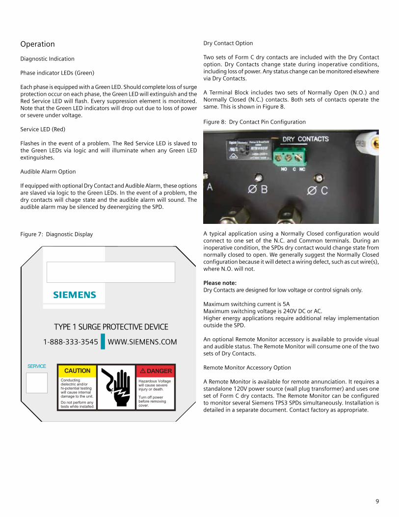
DryContactOption
TwosetsofFormCdrycontactsareincludedwiththeDryContactoption. Dry Contacts change state during inoperative conditions,includinglossofpower.AnystatuschangecanbemonitoredelsewhereviaDryContacts.
A Terminal Block includes two sets of Normally Open (N.O.) andNormallyClosed (N.C.) contacts.Both setsof contactsoperate thesame.ThisisshowninFigure8.
A typical applicationusing a Normally Closed configurationwouldconnect to one set of the N.C. and Common terminals. During aninoperativecondition,theSPDsdrycontactwouldchangestatefromnormallyclosedtoopen.WegenerallysuggesttheNormallyClosedconfigurationbecauseitwilldetectawiringdefect,suchascutwire(s),whereN.O.willnot.
Please note:DryContactsaredesignedforlowvoltageorcontrolsignalsonly.
Maximumswitchingcurrentis5AMaximumswitchingvoltageis240VDCorAC.Higherenergyapplicationsrequireadditionalrelay implementationoutsidetheSPD.
AnoptionalRemoteMonitoraccessoryisavailabletoprovidevisualandaudiblestatus.TheRemoteMonitorwillconsumeoneofthetwosetsofDryContacts.
RemoteMonitorAccessoryOption
ARemoteMonitorisavailableforremoteannunciation.Itrequiresastandalone120Vpowersource(wallplugtransformer)andusesonesetofFormCdrycontacts.TheRemoteMonitorcanbeconfiguredtomonitorseveralSiemensTPS3SPDssimultaneously.Installationisdetailedinaseparatedocument.Contactfactoryasappropriate.
Figure8:DryContactPinConfiguration
9

Maintenance
SPDsrequireminimalmaintenance.Periodicinspectionofdiagnosticindicatorsisrecommendedtoensureproperoperation.
Troubleshooting&Service
Pleasecontactusforanyservicerelatedissues.
Quality SPDs withstand severe duty and attempt to protect theirloaduntil failure. There are electrical anomalies thatSPDs cannotprotect against. These are generally Sustained Overvoltages alsoknownasTemporaryOvervoltages(TOVs).Inthiscontext,SustainedOvervoltages may be only a few cycles. Failed SPDs tend to besymptoms,notrootcauses. AfailedSPD isusuallyasignofotherproblemswithintheelectricaldistributionsystem.Asageneralization,thesinglelargestcauseofSPDfailuresisreferencetogroundissues.IftheSPDshowsproblemsonstartup,thereisreasonablechanceofbonding/grounding/misapplicationissue.Thispermanentlydamagestheunit.Ifnotcorrected,itwillhappenagain.
WarrantyandCustomerService
LimitedWarranty
SiemenswarrantsitsACPanelprotectionproductsagainstdefectiveworkmanshipandmaterialsfor10years.LiabilityislimitedtotherepairorreplacementofthedefectiveproductatSiemens’option.AReturnMaterialAuthorizationnumber(RA#)mustbegivenbythecompanypriortothereturnofanyproduct.Returnedproductsmustbesenttothefactorywiththetransportationchargesprepaid.Inaddition,thecompanyalsowarrantiesunlimitedreplacementofmodularandcomponentpartswithinthewarrantyperiodpreviouslydescribed.
Thecompanyspecificallydisclaimsallotherwarranties,expressedorimplied.Additionally,thecompanyisnotberesponsibleforincidentalorconsequentialdamagesresultingfromanydefectinanyproductorcomponentthereof.
The sales contract contains the entire obligation of Siemens. Thisinstructionmanualshallnotbecomepartoformodifyanypriorexistingagreement,commitmentorrelationship.
TechnicalSupport
1.888.333.3545
Prior to calling Siemens TPS3 Technical Support for assistance ororderingparts,pleasehavethefollowinginformationavailable:
TPS3modelnumber:________________________________Manufacturedate:_________________________________DateofPurchase:___________________________________Yourordernumber:_______________________________
ReturnShipmentAddress:
Siemens-Attn:RA#___________1455058thStreetNorthClearwater,FL33760
CONDUCTING DIELECTRIC AND/OR HI-POTENTIAL TESTING WILL CAUSEINTERNAL DAMAGE TO TPS3 UNIT.Do not perform dielectric or high potential
tests with the TPS3 unit installed.
CAUTIONVHazardous voltage.Will cause death or serious injury.Keep Out.Qualified personnel only.Disconnect and lock off all power before working on this equipment.
V DANGER
10

11

SiemensIndustry,Inc.BuildingTechnologiesDivision5400TriangleParkwayNorcross,[email protected]
8.9.10.al#8174