user manual - soft-blast.com · 4 jksimblast software installation before proceeding: for windows...
TRANSCRIPT

blast simulation evaluation and
management
User Manual


JKSimBlast i
Copyright © JKTech 1998, Soft-Blast 2006All rights reserved.
Both the software and documentation of JKSimBlast,2DBench, 2DRing, 2DFace, JKBMS, 2DView, TimeHEx,Design Importer, StockView and Units are copyright.
JKSimBlast is supplied and supported by:
Soft-Blast Pty LtdABN 38 429 050 791 tel: +61 7 3201 20111 Kynuna Court fax: +61 7 3201 2022Karana Downs email: [email protected], Australia 4306 web: www.soft-blast.com
JKSimBlast is produced by:
JKTechJKMRC Technology TransferUniversity of Queenslandwww.jktech.com.au
UserSupport

ii JKSimBlast
Disclaimer
JKSimBlast is a suite of powerful modular tools for thesimulation and management of blasting data. 2DBench,2DRing, 2DFace, JKBMS, 2DView, TimeHEx, DesignImporter, StockView and Units are stand-alone modules ofJKSimBlast: 2DBench, 2DRing and 2DFace are used forthe design and editing of blasts in mining and relatedapplications; JKBMS is used to organize and display thedata associated with blasting; 2DView and TimeHEx areextended analysis programs for JKSimBlast blasting data;Design Importer imports data from text files directly to theblast databases; StockView is for the storage of thespecifications of explosives and accessories; and Units isfor the management of user-defined systems ofmeasurement. As the program developers do not controldata creation, collection, analysis or interpretation, it is thesole responsibility of the user to verify that input data areaccurate and appropriate, and that all conditions andoutputs are reasonable and comply with any statutoryrequirements.
In no event will Soft-Blast or JKTech be liable for direct,indirect, special, incidental or consequential damagesarising out of the use of or inability to use the software ordocumentation.

JKSimBlast iii

iv JKSimBlast
ContentsI n t r o d u c t i o n . . . . . . . . . . . . . . . . . . . . . . . . . . . . . . . 1
Overview ...............................................................1
Conventions...........................................................2
Equipment Requirements ......................................3
Software Installation ..............................................4
Electronic Security Key ....................................14
License File......................................................14
Fast Program Start...........................................15
J K B M S . . . . . . . . . . . . . . . . . . . . . . . . . . . . . . . . . . . . 1 7
Overview ..........................................................17
Appearance......................................................18
Data Structure..................................................19
Using BMS.......................................................20
Window Size ....................................................21
General Features.................................................22
Menus ..............................................................22
Function Toolbar ..............................................23
Object Toolbar .................................................24

JKSimBlast v
Blast Displays .................................................. 26
Help ................................................................. 27
Program Settings................................................. 28
Options ............................................................28
Tools and Functions ............................................ 31
Edit .................................................................. 31
Recycle Bin...................................................... 32
Searches ......................................................... 33
Reports ............................................................ 34
Utilities............................................................. 37
J K B M S T u t o r i a l . . . . . . . . . . . . . . . . . . . . . . . . . 4 1
Setup...................................................................41
New Database..................................................... 41
Root Object ......................................................... 42
Add Object .......................................................... 43
Add Blasts...........................................................46
Add Blast from 2DBench.................................. 47
Import Blasts from a 2DBench Database ......... 48
Create Blast.....................................................51
Edit the Blast ....................................................... 52

vi JKSimBlast
Analyse the Blast.................................................53
2 D B e n c h . . . . . . . . . . . . . . . . . . . . . . . . . . . . . . . . . . 5 7
Overview .............................................................57
Appearance .........................................................58
Design Modes......................................................59
General Features.................................................59
Toolbar.............................................................59
Cursor ..............................................................60
Selection Box / Mask........................................60
Zoom................................................................60
Blast Parameters..............................................60
Marking ............................................................60
Query (information display) ..............................61
Help .................................................................61
Sample Blasts ..................................................61
Tools & Keys....................................................62
2 D B e n c h T u t o r i a l . . . . . . . . . . . . . . . . . . . . . . 6 5
Creating a Blast Design....................................65
Lines, Polygons and Labels..............................65
Drilling Holes ....................................................65

JKSimBlast vii
Saving the blast ...............................................67
Loading Decks ................................................. 68
Downhole Delays .............................................69
Surface Delays................................................. 69
Detonation Simulation ...................................... 71
Basic Analyses................................................. 72
2 D V i e w . . . . . . . . . . . . . . . . . . . . . . . . . . . . . . . . . . . . 7 5
Overview .............................................................75
Opening a Blast................................................... 77
Open a Blast.................................................... 77
Add a Blast ......................................................78
Viewing a Blast....................................................80
Define View .....................................................80
Scroll Bars ....................................................... 83
Defining a View "Plane" ...................................84
Printing................................................................ 86
Calculation Region ..............................................88
Creating a Calculation Region ......................... 89
Polygon Method............................................... 89
Draw a Region................................................. 90

viii JKSimBlast
Modify Regions ................................................91
Explosive Energy Distribution ..............................94
Starting a Distribution Calculation ....................95
Calculation Parameters....................................96
Displaying Results............................................98
4D Energy Distribution ...................................100
2DContour .........................................................102
Contour Control..............................................103
Contour Scale ................................................106
Adding Custom Contour Values .....................108
T i me H E x . . . . . . . . . . . . . . . . . . . . . . . . . . . . . . . . 1 1 1
Overview ...........................................................111
Maximum Instantaneous Charge .......................112
Design View.......................................................116

JKSimBlast ix

x JKSimBlast

JKSimBlast 1
I n t r o d u c t i o n
OverviewJKSimBlast covers the design, editing, simulation, analysisand management of blasting in mining and relatedoperations. The main modules are 2DBench, 2DRing and2DFace. These are graphical software programs for thedesign and editing of blasts: 2DBench applies to benchblasting in surface mines; 2DRing applies to undergroundring blasting; and 2DFace applies to underground tunnelingand development. The three programs give engineers andblasting personnel the ability to design and optimise thelayout and initiation sequence of almost any type of blastused in mining. Each allows the designer to:
layout a pattern of blastholes
load explosive decks and other materials in the holes
install downhole and surface delays, with primer andconnection details
simulate the detonation on screen
import and export data and print the blast
Individual elements of the blast are defined by the user,including hole dimensions, explosives, delays, connectorsand boosters, and can be combined in a variety of blastscenarios.
The design modules include detailed analysis tools tocalculate blast properties, summarise quantities andconsumables, and interpret blast performance. Othermodules in JKSimBlast provide for extended analysis ofblast layouts and energy (2DView, Energy and 2DContour)and blast timing (TimeHEx). Data management is
Overview

Introduction
2 JKSimBlast
provided by JKBMS (Blast Management System). ThusJKSimBlast is a framework for a suite of programs for datamanagement in blasting, including design and simulation,analysis, data collection and referencing, performanceevaluation, prediction and optimisation. Integration of themodules is achieved through data sharing via MicrosoftAccess databases. The open framework allows for otherthird party applications to be developed and incorporatedinto JKSimBlast, using the same databases for their ownpurposes. This approach provides the user with amechanism to maximise the use of the data.
This manual describes the basic and commonly usedfeatures of the programs. More detail on JKSimBlast andthe modules is contained on the CD and in the varioussections of this manual, and in the on-line help with eachmodule.
Conventions[click] click the left mouse button once
[double click] click the left mouse button twice
[right click] click the right mouse button once
[drag] click and hold the left mouse button, move themouse, then release the left mouse button
[…] press the key, button or tab showndo not press [Shift] unless indicated
[…]+[…] press the keys together
>italic means a menu option
Conventionsused in thismanual

Introduction
JKSimBlast 3
Equipment RequirementsJKSimBlast runs on a personal computer under MicrosoftWindows 98 / NT4 / 2000 / XP. The recommendedminimum requirements for running JKSimBlast are:
16 MB of random access memory (RAM)
CD disk drive (for installation)
hard disk drive with 65 MB of free space, plus 85 MBof temporary free space for installation
SVGA graphics (800 x 600 display)
mouse
The installation program requires about 85 MB of freespace for the temporary installation files, which areremoved when the installation is completed. The full suiteof JKSimBlast program files occupy about 45 MB of diskspace, with a further 20 MB taken up by system files,mostly in the Windows System folder. Some of these filesmay be already present on the computer, so the final diskspace requirement may be less than that stated above.Additional space will be required for blast database filescreated by the user in the operation of the program.
All JKSimBlast modules are designed for SVGA graphics(800 x 600 pixels). Although it will operate in VGA mode(640 x 480), some of the items may be obscured or cut offin the smaller screen area, such as dialog boxes, querywindows and status line messages.
JKSimBlast uses an electronic security key, which must beattached to the computer before each module can run.Additional and replacement keys can be obtained fromSoft-Blast.
EquipmentRequirements

Introduction
4 JKSimBlast
Software InstallationBefore proceeding:
For Windows NT, 2000 or XP, you may needAdministrator privileges for software installation.
JKSimBlast uses an electronic security key and a matchinglicense file as the license control for the software. You willneed both of these items to run the software.
Installing JKSimBlast
The installation program for JKSimBlast is used to installany or all of the modules, plus the drivers for the electronicsecurity key. You have a choice to install either a completesystem for Surface Blasting or Underground Blasting, orindividual components (see the JKSimBlast overview onthe CD for more details).
You will need an appropriate license file to run the mainmodules of JKSimBlast - JKBMS, 2DBench, 2DRing,2DFace, 2DView, Energy, 2DContour and TimeHEx. Thisfile is supplied as part of the purchase of the software.Instructions for installing the license file are at the end ofthe section below. The utility modules StockView, Importand Units do not require a security key or license file inorder to operate.
In the installation instructions, [disk]: refers to the driveletter of your CD drive.
SoftwareInstallation

Introduction
JKSimBlast 5
1. Start the installation programTo install all of the modules in JKSimBlast, you will needabout 150MB of free space on your hard drive. Thisincludes 85MB of temporary space for the install program.Installing only one module, such as 2DBench or 2DRing,requires about 120MB.
To start the installation, run the program
[disk]:\install\JKSimBlast\Setup_JKSimBlast_v2.exeSelect [Open] or [Run from this location] if the programdoes not start by itself. Alternatively, you can copy theinstall program to a hard drive and run it from there.
Once the installation program starts, follow the on-screeninstructions.
2. Wait ...The install program will create a temporary folder on yourhard drive to hold the extracted installation files. This is avery large file, so it could take a few minutes. For example,on a 500MHz computer running Windows 2000, theextraction can take up to 1½ minutes. Please be patient.

Introduction
6 JKSimBlast
3. License Agreement[Click] the button to accept the license agreement andproceed. A copy of the license agreement is on the disk, inthe JKSimBlast install folder.
Introduction
JKSimBlast 7
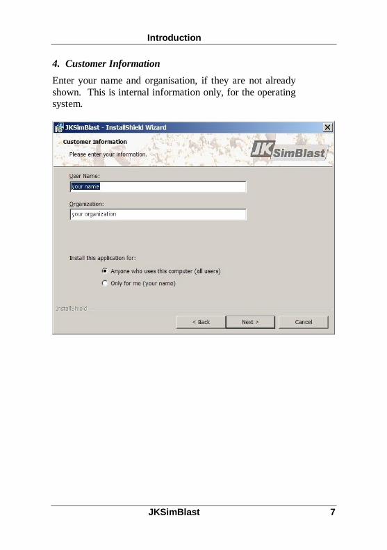
4. Customer InformationEnter your name and organisation, if they are not alreadyshown. This is internal information only, for the operatingsystem.

Introduction
8 JKSimBlast
5. Destination FolderEither accept the default installation folder, or click[Change] to select a new folder.
Introduction
JKSimBlast 9
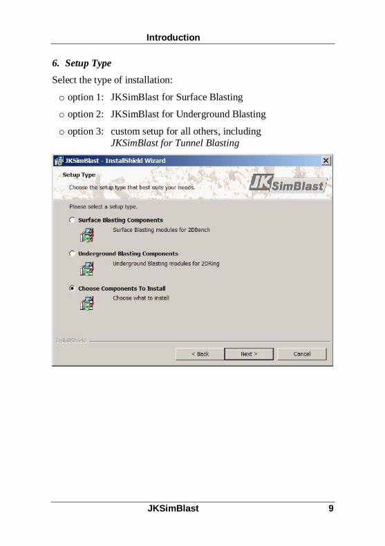
6. Setup TypeSelect the type of installation:
o option 1: JKSimBlast for Surface Blasting
o option 2: JKSimBlast for Underground Blasting
o option 3: custom setup for all others, includingJKSimBlast for Tunnel Blasting

Introduction
10 JKSimBlast
7. Custom SetupUse the Custom Setup to install individual components.Note that the components StockView, Import and Units arealways installed.
To install JKSimBlast for Tunnel Blasting, select thecomponents 2DFace, TimeHEx, 2DView and JKBMS.

Introduction
JKSimBlast 11
Select how and when to install each component - typically,always select the first option ...

Introduction
12 JKSimBlast
For example, to install only 2DBench, the screen shouldlook like this ...

Introduction
JKSimBlast 13
8. Ready to installThe software is now ready to install. Check the details, andclick [Install] to continue.

Introduction
14 JKSimBlast
Electronic Security KeyAll of the main JKSimBlast modules require an electronicsecurity key to operate. The drivers for running either aUSB key or an LPT key (for the parallel printer port) areinstalled with the program.
The Hardlock drivers can also be installed independently, ifrequired, by running the program hldrv32.exe from theHardlock folder on the CD.
License FileTo complete the installation, copy the license filelicense.nfo to the main JKSimBlast folder (typicallyC:\Program Files\JKSimBlast). The license file containsdetails of the modules that are permitted to run witheach electronic security key.
The license file should either be on the CD in theJKSimBlast folder, or supplied by email as an attachment.If you do not have a license file, contact Soft-Blast.Include the name of your organisation, contact person andthe serial number of your electronic security key.
Once the license file is in place, plug in the security keyand start the software.
ElectronicSecurity Key
License File
Introduction
JKSimBlast 15
Fast Program StartThe programs JKBMS, 2DBench, 2DRing and 2DFacemay take a long time to start at the first run, but should startalmost immediately on subsequent runs. At the first run,the programs search internally for details of the electronicsecurity key. These details are then stored in aninitialisation file in the program folder, and are used insubsequent runs to enable faster start-up.
If a program does take a long time to start, a fast start canbe forced by modifying the shortcut to the program. Select>Help >About, and note the code in square brackets at thebottom of the form, e.g. [G123]. [Right click] on anyshortcut for starting the program (including the Startmenu), and select Properties from the pop-up menu. At theend of the Target line, add /local=G123. For example:
"C:\Program Files\JKSim…2DBench.exe" /local=G123Close the Properties, then restart the program from theshortcut. It should start almost immediately.
For a network license, the code is in the form [Nnnn], andthe startup command is /net=Nnnn.
Fast ProgramStart

Introduction
16 JKSimBlast

JKSimBlast 17
JK B M SOverview
The Blast Management System (BMS) allows the user tostore, organise and access information related to drill andblast operations in mines. The information can include pitand blast geometry, geotechnical and blasting domains,drilling parameters, costs, fragmentation distributions,vibration results, specific reports, comments, etc.
The BMS uses an object based approach in a hierarchicaltree structure for the storage and management of blast data.Information attached to an object is stored in a MicrosoftAccess database linked to the program, either as a set ofdata relevant to the object or as a pointer to a separate filewhere the data is stored. This avoids duplication and keepsthe size of the BMS database to a minimum, and ensuresthat other programs can continue to access external datafiles without any limitations imposed by the BMS.
Although the BMS can store production data for drill andblast operations, it is not intended to replace or act as acontinuous production reporting system. Its purpose is toorganise blasting information, in order to facilitate thedesign, modification and analysis of blasts. Often, whiledesigning a new blast or making ongoing modifications toa current blast, an engineer or blaster may need to includespecific parameters or review results from previous blasts.The BMS can provide rapid access to that information in asimple, intuitive format.
The program both complements and extends the use of theJKSimBlast blast modules 2DBench, 2DRing and 2DFace.This manual describes the setup for an open pit database,highlighting its connectivity with the 2DBench module.Apart from minor differences in the types and appearanceof some of the objects and their data, the process is thesame for the other blast modules.
Overview
JKBMS
18 JKSimBlast
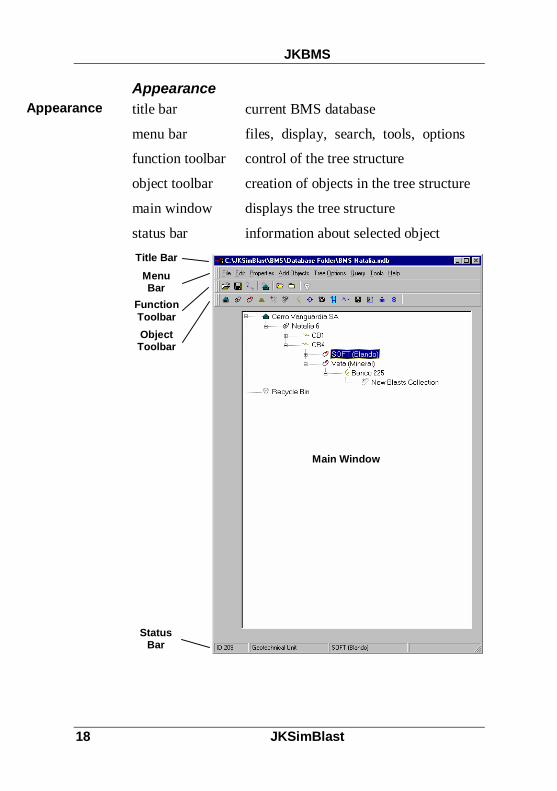
Appearancetitle bar current BMS database
menu bar files, display, search, tools, options
function toolbar control of the tree structure
object toolbar creation of objects in the tree structure
main window displays the tree structure
status bar information about selected object
Appearance
ObjectToolbar
FunctionToolbar
StatusBar
Main Window
Title BarMenuBar

JKBMS
JKSimBlast 19
Data StructureThe BMS uses hierarchical, or parent-child, relationships tobuild a tree structure of the blast data. Each type of dataobject (e.g. pit, bench, blast) is given a uniqueidentification, and can be both a child of one object and aparent to others. A single sequence of parents and childrenis called a branch, with each point in the branch, called anode, holding one object. The starting point for a tree iscalled the root object. A single BMS database can haveseveral root objects, and thus several trees.
Each object in the tree is defined by three properties: itsunique object ID number (shown in the status bar), itsparent’s ID number, and the object type. Each object alsohas a name which can be modified by the user.
Information is added to an object either by [double-click]on the object or [right-click] and select an option from thepop-up menu. Some objects do not accept any furtherinformation (such as open pit or blast collection), and onlyexist to help create a logical tree structure, similar to afolder in Windows Explorer. Other objects hold data aboutthe object or a link to an external data source, or in somecases both. In particular, detailed blast information isstored in the original 2DBench, 2DRing or 2DFace
Data Structure
RootObject
Children
Parent ofDomainObjects

JKBMS
20 JKSimBlast
databases, and the BMS program communicates directlywith these databases.
In general, objects can be added to the tree at any positionthat the user wishes, except for a few particular objectscontrolled by in-built rules. For example, a blast can onlybe added to a blast collection.
Using BMSBMS stores its data in a Microsoft Access database, withthe extension “.bms”. The databases are fully compatiblewith MS Access and can be opened in MS Access. Thisshould be done with care, to prevent accidental changes ordamage to the structure or contents of the database.
Any number of BMS databases can be created, but onlyone can be opened at a time. Databases can be created asnew databases or from a subset of the current database.Several databases can also be merged into one database byinserting in the current database.
It is recommended to create new databases to prevent adecrease in performance of the program caused byexcessively large database files. If this occurs, separate thedatabase into logical units, for example by date, location orapplication.
While the BMS program is in use it remains attached, orbound, to the current database. This means that anychanges made in the program are immediately stored in thedatabase. This is different from the other programs inJKSimBlast, which do not save any changes until Save isselected from the menu.
Using BMS

JKBMS
JKSimBlast 21
When a BMS database is opened, it is locked to preventother users from making changes. However, other userscan view the contents of a locked database in read-onlymode. The program checks at regular intervals for the lockfile (*.ldb), which is removed when the first user closes hiscopy of BMS. A new lock file is then created for the nextuser, and the data tree is rebuilt to include any changesmade by the previous user.
The BMS can also open blast databases from 2DBench,(*.2db), 2DRing (*.2dr) and 2DFace (*.2df). However,only some limited functions can be performed in this mode.
o Use only the options under the pop-up menu ([right-click] on a blast): delete, cut, copy, paste, rename, andproperties.
o Do not use any other functions under the menus, exceptthose listed above. The menus are not disabled, but ifany other items are selected, the program will crash.
Window SizeBMS is primarily designed to work with the blast designand analysis modules of JKSimBlast: 2DBench, 2DRingand 2DFace. To facilitate this, if the BMS window isplaced on either the left or right side of the screen, andreduced to less than 1/3 of the screen width, the designmodules will open automatically in the remaining space.This will allow the user to move easily between the twoprograms. If more than one design module is open, theywill all occupy the same space on the screen.
Window Size

JKBMS
22 JKSimBlast
General Features
MenusTwo menus are available in BMS. The main menu islocated at the top of the screen, immediately below the titlebar. All of the program functions (except some specificblast functions) can be accessed from the main menu.
The menus also show any corresponding keystrokes thatcan activate the same functions.
main menu
A secondary menu can be opened by a [right-click] withthe mouse on any object. Most of the options in this menuare available from the main menu, but some objects willshow additional options: in particular, a blast collectionwill include options for creating and importing blasts, and ablast will include options to create specific reports.
pop-up menu
Menus

JKBMS
JKSimBlast 23
Function Toolbar
The function toolbar includes the main tools to open andsave databases and display the tree structure.
Open Database open an existing database formodification (if not already in use) or displayonly (if in use).Menu option: >File >Open Existing Db
Save As… save the current database under a newname
Create New Database create a new, empty BMSdatabase, from the template file Template.mdb inthe Templates sub-folder
Add New Root Object create a new top-level nodeon the tree. This must be done first for a newdatabase.
Open All Branches expand all branches in the tree,so that all nodes are visible.
Close All Branches shrink all branches in the tree,so that only the root objects are visible.
Show Recycle Bin opens the recycle bin in aseparate window. If the recycle bin contains anyobjects, it will also be visible on the tree.
Clear Search Results clears the list of found objectsfrom the last search.
go directly to found items:first, previous, next, last
FunctionToolbar

JKBMS
24 JKSimBlast
Object ToolbarThe object toolbar and the >Add Objects menu containvarious items that can be added as nodes to the tree.
Object Toolbar

JKBMS
JKSimBlast 25
To add a node, first select the parent node, then [click] anyitem on the object toolbar to create it as a child node.
Objects in the tree have generic and specific properties.Both of these are accessible from the >Properties menu,but only the specific properties appear in the pop-up menu([right-click] on an object in the tree).
In most cases, a [double-click] on an object will display thespecific properties. The major exception is the generic fileobject, which will activate the linked file.
The generic properties include the dates when the objectwas created and last modified, and the name of the userprofile at the time. Descriptions, comments and notes canalso be added to the generic properties.
The specific properties depend on the purpose of the object.
o No properties - the object is only used to help definethe structure of the tree, e.g. open pit
o Description - these describe the object, but are notused for any other purpose, e.g. top andbottom levels for a bench
o Data Store - the object has data stored with it in theBMS database, e.g. surface, graph, joint sets
o Collection - a holder for other, specific objects, e.g.blasts, photos, energy distributions. Onlythese objects can be added to the collections.
o File Link - stores the name and location of an externalfile, e.g. generic, photo and videocollections.
o Blast Link - stores the blast and database name andlocation for blasts created in the JKSimBlastdesign modules.

JKBMS
26 JKSimBlast
Blast DisplaysThere are two types of display for blasts, in 2D or 3D.
All blasts are displayed in 2D with the specific propertiesfor a blast collection. Bench blasts are displayed in plan,and ring and face blasts are projected to a section viewlooking in one of the main orthogonal directions (north,south, east, west, up, down).
Bench blasts can also be displayed in a separate plan viewwindow, by [right-click] and select Plan View from thepop-up menu. This can be done for any node on the tree,and all bench blasts in branches below that node will bedisplayed.
Blast Displays

JKBMS
JKSimBlast 27
The 3D Viewer can display any blast, plus also surfaces,energy distributions and PPV distributions. As for the planview, this can be activated at any node in the tree to displayall relevant data attached to the branch.
HelpOn-line help is accessible from most dialog boxes andforms, either from a [Help] button or by pressing the [F1]key.
Help

JKBMS
28 JKSimBlast
Program Settings
OptionsWhen you first run the JKBMS you can immediately beginto use it to start organising the blasting related data for yourmining operation. However, there are a few options youwill first need to set under the >Tools >Options menu tosave having to set them later on.
The settings are stored in the Windows registry whereJKBMS is installed.
Nodes
Return to Last Node on Start Up: If you want to goback to the last node visited each time you open theprogram, check this option.
Open Tree on Start Up: If this option is leftunchecked then the tree will not appear fully open whenyou start the program. If the previous option is checkedthen the tree will only open up the direct ancestors ofthe last node visited. If it is checked then all nodes willbe shown (i.e. the tree will be fully open) and thecurrent node will be highlighted.
Confirm Addition of New Children: The programwill ask for confirmation each time you add a node.
Confirm Node Deletion: The program will ask forconfirmation each time you delete a node.
Double Click runs file in associated externalprogram: If the node is a generic file object, a [double-click] on the node will open the file in its associatedprogram, as defined in the specific properties for thenode. If the node is a blast, it will open the blast in therelevant JKSimBlast design module.
Options
JKBMS
JKSimBlast 29
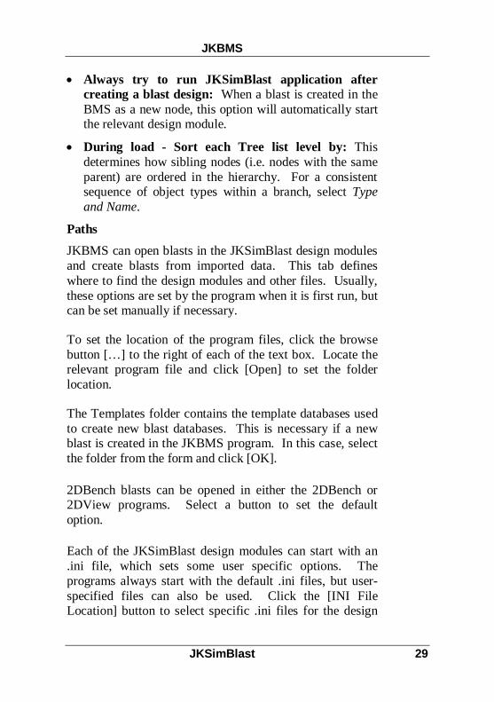
Always try to run JKSimBlast application aftercreating a blast design: When a blast is created in theBMS as a new node, this option will automatically startthe relevant design module.
During load - Sort each Tree list level by: Thisdetermines how sibling nodes (i.e. nodes with the sameparent) are ordered in the hierarchy. For a consistentsequence of object types within a branch, select Typeand Name.
PathsJKBMS can open blasts in the JKSimBlast design modulesand create blasts from imported data. This tab defineswhere to find the design modules and other files. Usually,these options are set by the program when it is first run, butcan be set manually if necessary.
To set the location of the program files, click the browsebutton […] to the right of each of the text box. Locate therelevant program file and click [Open] to set the folderlocation.
The Templates folder contains the template databases usedto create new blast databases. This is necessary if a newblast is created in the JKBMS program. In this case, selectthe folder from the form and click [OK].
2DBench blasts can be opened in either the 2DBench or2DView programs. Select a button to set the defaultoption.
Each of the JKSimBlast design modules can start with an.ini file, which sets some user specific options. Theprograms always start with the default .ini files, but user-specified files can also be used. Click the [INI FileLocation] button to select specific .ini files for the design

JKBMS
30 JKSimBlast
modules. Ensure that the [Use these Ini Files...] checkboxhas been selected.
If you have the Split-Desktop program (image analysis ofphotos of fragmentation), you can also set the path to theprogram. The fragmentation object has an option toactivate the program with the attached photos.
ViewingThese options determine how blasts and other data aredisplayed in the 3D Viewer.
Show Strings with Blasts: Any strings in a blast willbe displayed along with the blast. Turn this off if theperformance of the 3DViewer is being affected.
Show Ties with Blasts: Shows surface delayconnections with the blast.
Show Holes as... Either show blast holes as cylinders(drawn to scale), or only as the centre line of the hole.This will also affect the performance of the viewer.
3DView Far Plane Value: The distance at which therendered objects in the 3D Viewer are clipped. See theon-line help for The Eye and Target Coordinate Displayfor more information.
3DView Default Background Colour: Thebackground colour of the render window in the 3DViewer. [Click] the coloured box to change the colour.
3DView Default Blast Colour: The default colourwhich blasts are shown in. If a colour has been definedin the generic properties of the blast object, then thisoverrides this value. [Click] the coloured box to changethe colour.

JKBMS
JKSimBlast 31
Miscellaneous
The Misc. tab contains options for using stocks (explosivesand accessories) and units in the JKBMS. These optionsare used with Blast Result and Cost objects, and forexporting data for reports.
See the on-line help for more information.
Tools and Functions
EditThere are several tools for modifying objects in the tree.These tools are available from either the pop-up menu orthe >Edit menu.
Note: there is no Undo. Once an editing tool has beencompleted, it is not possible to restore the object to itsprevious condition.
Delete Object
Move an object and all its children to the Recycle Bin.These objects can be restored until the recycle bin isemptied.
Rename ObjectChange the name of an object in the tree. This does notaffect the names of any specific properties or linked data.
Move Object to Root
Moves an object from its current parent to the top-level inthe tree. This can also be done by deleting the object andrestoring from the Recycle Bin as a root object.
Edit

JKBMS
32 JKSimBlast
Cut
Move object to the cut buffer. Note that the cut bufferoperates differently to the normal windows buffer in thatyou can cut several objects and then paste them all to thesame parent. The cut objects are also persistent, i.e. theywill remain in the cut buffer of the database, even if theprogram is closed, until they are pasted.
Copy
Make a copy of an object and insert it as a sibling to theoriginal object, i.e. under the same parent. You have theoption of copying the object specific information as well(i.e. not just the generic properties). To copy to a differentparent, first copy, then cut the copy and paste under adifferent parent.
PastePaste any cut objects as children of the selected node.
Recycle Bin
The JKBMS Recycle Bin operates in much the same wayas the Windows Recycle Bin. Any deleted object goes tothe recycle bin before actually being removed from thedatabase. Any object in the Recycle Bin can be restored aseither a child of the current node, child of its old parent (ifit still exists) or as a root object.
The Recycle Bin appears automatically on the tree if itcontains any objects. To display it, either [double-click] iton the tree, or [click] the [Recycle Bin] button on the maintoolbar.
Recycle Bin

JKBMS
JKSimBlast 33
To empty the Recycle Bin, [right-click] on the Recycle Binnode and select Empty Recycle Bin from the popup menu.
SearchesThere are four search tools provided in JKBMS. In allcases, the search results are placed in a list, and each itemcan be quickly accessed by the Goto buttons on the toolbar.
Found objects are indicated in the tree by a bold font. Ifthe node is not visible, because the branch is closed, theparent node is highlighted. If the Goto buttons are used,the branch will be automatically opened.
go to items in search list:first, previous, next, last
clear the found list. All of the searchesinclude [Reset] buttons to clear the list.Rebuilding the tree will also clear the list.
The four searches are located under >Edit >Find and>Tools> >Query.
Find / Quick QuerySearch the generic properties to find objects by name, typeor date.
Query Builder
A more advanced version of the Quick Query for genericproperties only.. The criteria from this search cannot besaved by in the BMS, but can be copied and pastedbetween the criteria box and another application
Searches

JKBMS
34 JKSimBlast
3D Query
Search for either blasts or survey points by theircoordinates. Enter a single point as the centre of thesearch, and a window range in each direction around thecentre. The search will locate any data points attached toblasts or survey points that fall within the window. Thecriteria for this search can be saved and recalled again forlater use.
Find Blast By ResultSearch Blast Result and Fragmentation objects for a blast.In this case, the parent blast of the successful results isselected. The criteria for this search can be saved to anexternal file.
ReportsJKBMS can generate several Excel reports for blasts.These can be accessed from either the >Tools menu or thepop-up menu for a selected blast. For further informationabout the included Excel reports, consult the on-line help.
There are two other reporting options that export the blastdata as text files.
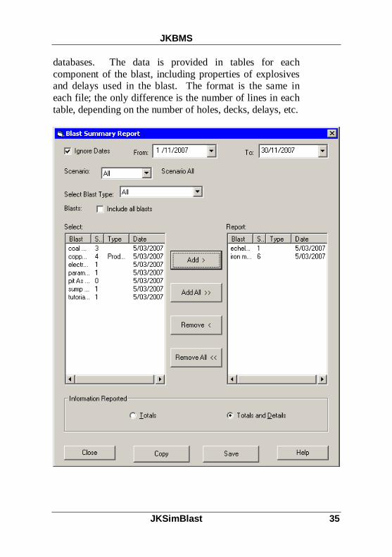
The first output, the Blast Summary Report, creates asummary of the various components of the blast: holes,explosives, and delays. All of the data is exported to asingle file that contains a short summary of the totals foreach blast, and the total for all blasts, followed by thedetails for each blast for each of the blast components.(Note: the Summary Report can only report bench blasts.)
The second output, the Export Report, contains all of theraw data for the selected blasts, with one text file per blast,with the name of the blast as the file name. This is,basically, a download of the data stored in the blast
Reports
JKBMS
JKSimBlast 35
databases. The data is provided in tables for eachcomponent of the blast, including properties of explosivesand delays used in the blast. The format is the same ineach file; the only difference is the number of lines in eachtable, depending on the number of holes, decks, delays, etc.

JKBMS
36 JKSimBlast
The Export Report also includes a bitmap image file foreach blast. The file has the same name as the text file, withthe extension .bmp. In the case of ring blasts, there is onebitmap file per ring.
Both outputs are tab-delimited, which makes them suitablefor opening in a spreadsheet and further formatting andcalculation.

JKBMS
JKSimBlast 37
Both report options operate in a similar fashion. Thedialogs present a list of blasts from which the user canselect for export. The list can be filtered by date, scenarioor blast type. Export Report also includes options for theblast components to include and the details shown in theblast image.
Initially, only blasts below the selected node are shown inthe list. To include all blasts in the current BMS database,select the check box for [Include all blasts].
In Blast Summary Report, click [Copy] to send the outputdirectly to the clipboard, or [Save] to write to a nominatedfile.
In Export Report, click […] to select the folder where theouptput files are to be stored, then [Continue] to producethe files. The files can also be sent directly to anotherapplication for processing, if it is defined in the [Activate]list.
UtilitiesJKBMS includes several utilities for manipulating the treestructure, file links and blast databases. These include:
extracting a subset of the current BMS database (prune);
merging BMS databases (insert database);
display only one branch = hide other branches (prunethis branch);
repair links to external files, e.g. when the files havebeen moved to another folder;
move and copy external files from within BMS;
Utilities

JKBMS
38 JKSimBlast
archive a BMS database and all linked files;
move or copy blasts from one blast database to another.
These utilities are discussed in the on-line help.

JKBMS
JKSimBlast 39

JKBMS
40 JKSimBlast

JKSimBlast 41
JK B M S T u t or i a l
SetupThis tutorial will take you through the basic steps forcreating a BMS database.
A BMS database must contain at least one root object.Further objects are added to the tree to represent thedistribution of the data, either by location or relationship, orboth. As each object is added, specific properties areentered to create records of the blasts. Other files areadded to build a complete history of blasting operations.
The first step is to start the program. Enter a name on thestart screen – this will be the name of the user profile. Thisis used to recall the last settings for that profile.
If this is the first time that the BMS program has been usedafter installation, it should ask you several questions aboutstoring the profile and file associations. If it does not, or ifyou wish to change them, check the options under ProgramSettings.
New DatabaseTo create a new database, [click] the button on the toolbaror select >File >Create New Db.
Setup
New Database
JKBMS Tutorial
42 JKSimBlast
You will be prompted to enter a name for the new database,and select a folder. The BMS database canm be storedanywhere on your computer system.
Alternatively, you can objects to the current BMS database.
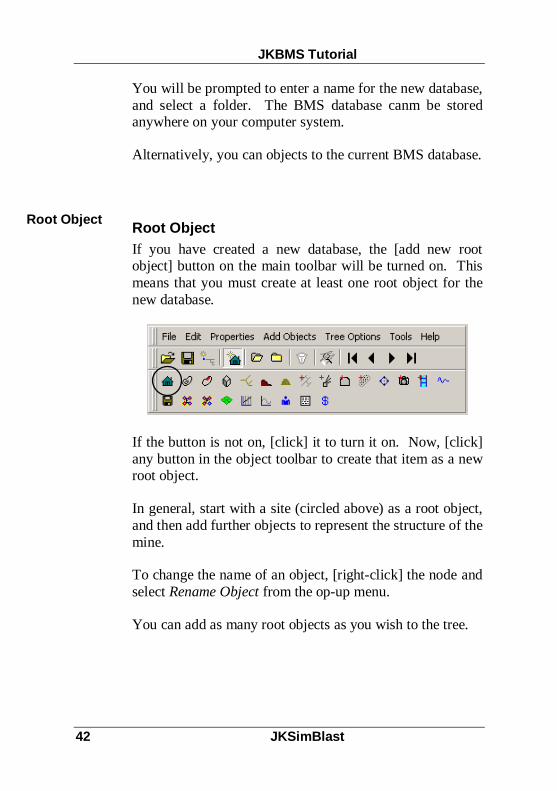
Root ObjectIf you have created a new database, the [add new rootobject] button on the main toolbar will be turned on. Thismeans that you must create at least one root object for thenew database.
If the button is not on, [click] it to turn it on. Now, [click]any button in the object toolbar to create that item as a newroot object.
In general, start with a site (circled above) as a root object,and then add further objects to represent the structure of themine.
To change the name of an object, [right-click] the node andselect Rename Object from the op-up menu.
You can add as many root objects as you wish to the tree.
Root Object

JKBMS Tutorial
JKSimBlast 43
Add ObjectTo add objects as nodes, first select the parent node on thetree by a single [click] on the node. Then, [click] one ofthe icons in the object toolbar to add that as a child nodebelow the selected node.
To add another object as a child to the same node, [click]the desired icon in the object toolbar. You can add as manynodes as you wish at one time, including duplicates of anyobject.
As it is added, each node is assigned a unique ID number inthe BMS database. The ID number, object type and objectname are displayed in the status bar at the bottom of thewindow when the node is selected.
The main concern at this point is to create a reasonablehierarchy for the tree that represents the structure of your
Add Object

JKBMS Tutorial
44 JKSimBlast
mine. This will make it easier to quickly locateinformation in the tree, which could be crucial to thecorrect design and recording of blasts. It is possible tomodify the tree later, but good planning now is a betterapproach.
In this case, the mine has two pits. Two benches have beenidentified within one pit for entry, as well details of a rockmass within the pit. Objects for each of these have beenadded to the tree.
A geotechnical unit is a zone of rock types and joints that istreated as a single domain for blasting. Its purpose is toquickly provide information about the rock mass, forreference only, when you are designing a blast.
When you add a geotechnical unit, also add child nodes forrock types and joint sets. The geotechnical unit displaysspecific properties for the dimensions of the domain, plus asummary of the specific properties from child nodes forrock types and joint sets.
The objects can be added to the tree in almost anysequence. For this example, the geotechnical unit couldhave been placed immediately under the site, if it is largeenough to encompass the entire pit. However, if a pit hasmore than one domain, then the domains could be placedinside the pit. Alternatively, all geotechnical units could beplaced in one branch together, separate from the other data,to reduce clutter in those branches and to make it easier tofind and maintain that data.
If you make a mistake in adding an object, select the nodeand press [Delete]. This will move it to the Recycle Bin.
To add specific properties to a node, [double-click] it orpress [Enter]. Some objects have no specific properties,

JKBMS Tutorial
JKSimBlast 45
such as a site (and are used only toorganize the structure of the tree), whileothers have either data or links toexternal data, or both. An open pit, forexample, has specific properties to helpto identify the location of the bench.
When the initial tree structure iscomplete, select each node in turn, press[F2] or [right-click] and select Rename
Object, and enter the name for each node.
To sort the tree, select >Tree Options >Rebuild. This willsort all objects at each level attached to a node according tothe selection in >Tools >Options. The figure below showsthe result for [Type and Name].

JKBMS Tutorial
46 JKSimBlast
Add BlastsTo add a blast, you must first add a blast collection. Thereare three collection objects, for bench, ring and face blasts.Each type of blast can only be added to its relevantcollection object.
To add a blast collection, select the parent node on the tree,then click the blast collection object on the toolbar.
There are three methods to add a blast:
add from a blast design module, such as 2DBench;
import from a JKSimBlast blast database; or
create the blast as a node.
Add Blasts

JKBMS Tutorial
JKSimBlast 47
Add Blast from 2DBenchFor this method, both 2DBench and JKBMS must berunning at the same time (the same applies for 2DRing and2DFace). Create the blast in 2DBench, and save it to ablast database. After you click the [Save] button in2DBench, and with JKBMS running, this dialog willappear:
Select the blast collection from the list, and click the button[Add Design to selected Blast Collection]. This will createa link, or reference, in the BMS database to the blast in itsblast database.
Otherwise, if you have selected the correct blast collectionnode in JKBMS, you can click the top button, [Add Designto current Blast Collection selected in JKBMS]. If youhave not selected it, you can go to JKBMS and select it

JKBMS Tutorial
48 JKSimBlast
before clicking the button. This is useful if you cannotdetermine the correct collection from the list.
You can click either of the [Add…] buttons to add morereferences to the blast, in any selected blast collection.
Click the [Close] button to close the dialog.
Import Blasts from a 2DBench DatabaseUse this method to add blasts that have been previouslysaved from 2DBench (or 2DRing, 2DFace).
[Right-click] on the blast collection node and select >AddExisting Blasts from the pop-up menu. This dialogappears:

JKBMS Tutorial
JKSimBlast 49
Click the [Open…] button to select a 2DBench database,and the blasts in the database will appear in the list below.Select the blasts to add; click with the [Shift] and [Ctrl]keys for multiple selections, click the [Select All…] for allblasts, or enter some characters in the filter at the bottomand click the [camera] button to select all blasts with thosecharacters.
The check box will limit the list to blasts that do notalready exist in the current BMS database.
Click the [+] button to add the selected blasts to the BMSblast collection. This will create a reference for each blast.

JKBMS Tutorial
50 JKSimBlast
[Double-click] the blast collection to display all of theblasts, with a plan view.

JKBMS Tutorial
JKSimBlast 51
[Right-click] the blast collection node and select >PlanView to show all of the blasts together in a single plan. Theview will show all of the blasts below the node from whereit was activated. Move the mouse over a blast to display itsname.
Create BlastThis option allows you to add a blast to a collection as anode. You can name the blast, and then choose to importthe blast data from a text file, or run the blast designmodule and create the blast there.
Select the blast collection, then [right-click] and select>Create New Blast. You will then be prompted to add theblast to a database – this is similar to saving the blast in thedesign module, but it only creates a location for the blast, itdoes not create any data.

JKBMS Tutorial
52 JKSimBlast
If you select [No] you will have a new blast with noreference. You can [right-click] on the new blast and select>Properties, then [double-click] the blast name to edit theblast details and attach a reference to an existing blast.
If you select [Yes], then you must select a blast databasewhere the blast will be linked. Select the database from thelist of current databases, browse for a different database, orcreate a new database (you will be prompted for a nameand folder).
Depending on your choice, you will then be prompted for aname and scenario number for the blast. If you enter orchoose a blast name that already exists in the database, youwill be prompted to create a reference to the blast. Select[Yes] to continue, or [No] to go back and enter a differentname or scenario.
Next, you will be asked if you wish to run the DesignImporter, to import the blast from a text file. This is thesame process as in the design modules to import a blast.
As the final step, the blast design module will open, andwill open the new blast if it exists, or you can create theblast.
Edit the BlastTo edit a blast in the relevant design module, either[double-click] the blast in the collection (if you haveselected the correct option in the program options), or openthe Properties in BMS (for either the blast or the collection)and click the edit icon in the top left corner of theproperties form.
Edit the Blast

JKBMS Tutorial
JKSimBlast 53
The blast will open in the relevant design module. Anypre-existing data will be lost.
Analyse the BlastJKBMS cannot perform any analyses within the program,but it can store or reference the results of analyses fromother sources, and these can be viewed in JKBMS. Thesecan be added to the blast as child objects, as for any otherobjects.
Some of the useful objects for analyses are:
Photo Collection. Each photo is stored as a link to afile, with individual notes. The photos can beviewed with the internal viewer, or opened in thedefault viewer application.
Video Collection. Each video is stored as a link to afile, with individual notes. The videos can beopened in the default viewer application.
Vibration. Enter the summarised results for variousvibration measurements.
Fragmentation Distribution. Enter the fragmentationdistribution data (as percent passing and size),and display as a graph. Several sets of data canbe entered, or pasted, and displayed together forcomparison.
Graph. Store and display time-based data as a graph.
Energy Distribution. A collection of energydistribution results from a JKSimBlast design
Analyse theBlast

JKBMS Tutorial
54 JKSimBlast
module. The data can be filtered to control thedisplay, and shown in 3D with the blast.
PPV Damage Contours. A collection of PPVcontour results from a JKSimBlast designmodule. The data can be filtered to control thedisplay, and shown in 3D with the blast.
Generic File. Attach any data file with anapplication that can process it. [Double-click] toautomatically run the application.
These objects are designed to make it easy to recall anddisplay other data associated with a blast, with allreferences stored in one location for rapid recall andcomparison. For more information, consult the on-linehelp.

JKBMS Tutorial
JKSimBlast 55

JKBMS Tutorial
56 JKSimBlast

JKSimBlast 57
2D B e n c h
Overview2DBench is a graphical program for the design and analysisof blasts in benching operations, typically for open cutmines and quarries.
The blast is laid out in a 2D plan view, consisting of blastholes, decks, and downhole and surface delays andconnections. The blast area can be further described bylines, polygons and labels (collectively known as strings).Both strings and blast holes can be imported from text files,either as designs or actual data.
Once the blast layout is complete, a detonation simulationcan be run on-screen. Basic analyses include volume,tonnage, powder factor, component and total costs and firstdetonation contours. Advanced analyses include maximuminstantaneous charge, energy distribution, PPV contours,dynamic burden relief, and fragmentation.
Although the blast is viewed in 2D plan, all data is createdand stored with full 3D coordinates (east, north, level) inMicrosoft Access databases. Added to this are componentdetails (hole parameters of dip, bearing, diameter, length,burden, spacing), properties of explosives, detonators,primers and connectors, and Monte Carlo detonation timinginformation.
The data from 2DBench can be further analysed in 2DView(in section and oblique views) for contouring of hole-related data and energy distribution and in TimeHEx (blasttiming vs holes and explosives) for arrival times andcumulative effect. 2DBench blasts and any related data canbe organized and viewed in JKBMS (Blast ManagementSystem).
Overview
2DBench
58 JKSimBlast
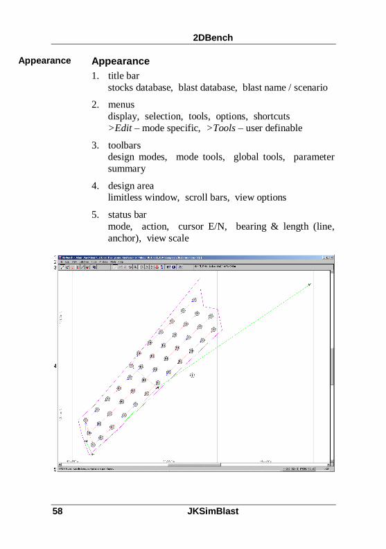
Appearance1. title bar
stocks database, blast database, blast name / scenario
2. menusdisplay, selection, tools, options, shortcuts>Edit – mode specific, >Tools – user definable
3. toolbarsdesign modes, mode tools, global tools, parametersummary
4. design arealimitless window, scroll bars, view options
5. status barmode, action, cursor E/N, bearing & length (line,anchor), view scale
Appearance

2DBench
JKSimBlast 59
Design ModesA blast is divided into five components, created in thevarious modes in the program. Each mode has specifictools and functions, plus there are several other tools forglobal editing, query, input and output functions.
Area draw and edit lines and polygons (called‘strings’), text labels
Drill drill and edit blast holes and nodes
Load insert decks – explosive and inert
Downhole insert down hole delays and boosters
Surface insert delays between holes and nodes
Detonation simulate detonation and analyse timing
General Features
ToolbarThe first group of buttons on the toolbar are the blastmodes: Area (lines, polygons, labels), Drill, Load,Downhole Delays, Surface Delays, and DetonationSimulation. The next button is the global parameter dialog– press this button in any mode to display the parametersdialog for that mode. The remaining buttons are tools forthe selected mode tools and global tools. The last section isa summary of the parameters in the selected mode.
Design Modes
GeneralFeatures

2DBench
60 JKSimBlast
CursorThe mouse can act as a pointer or cursor. To change to thecursor, put the mouse over the Design Area and [click],[Enter] or [spacebar]. To exit, [right-click] or [spacebar].You can move the cursor with the mouse or the arrow keys.Its position is shown by the coordinates on the status bar.
Selection Box / MaskThe selection box is a rectangular box; the selection maskis a multi-sided shape. Either is enabled when the toolbarbutton is “on”. The box and mask are used to mark holesor zoom in on the viewing area. To set the selection box,place the cursor for one corner of the box, then [drag] thecursor to the position of the opposite corner. For the mask,place the cursor and [drag] for the first side, then [click] foreach side – close by crossing the first side or [Esc].
ZoomYou can zoom in by pressing [Z] - zoom out by[Shift]+[Z]. The screen will zoom to the box or mask if itis active, otherwise zoom in or out will double or halve thewindow scale. The scale is shown at the bottom of thescreen. [Double-click] the scale to activate a zoom controlbox.
Blast ParametersBlast parameters (hole and pattern dimensions, type andamount of explosives and delays, etc) are entered via theparameters dialog. Activate the dialog, enter the values,click [Accept], and create the blast. Click [Save] to writethe parameters to an .ini file, and [Recall] to recall theparameters. Click [Close] to close the parameters dialog.
MarkingSelective actions, such as load, copy or delete, areperformed on marked holes and nodes, shown by a small M

2DBench
JKSimBlast 61
in the centre of the hole. Mark or unmark holes via the>Selection menu, [M] / [U] to mark / unmark the nearesthole to the cursor, or [Ctrl]+[M] / [Ctrl]+[U] to mark /unmark all holes. The number of marked and total holes isshown in the summary bar (e.g. mh 45/50).
Query (information display)[Click] the information display button at any time to see alldata for the current mode on the selected object (usually thenearest to the cursor).
HelpHelp is available from the >Help menu, or by clicking the[Help] button on the dialogs.
Sample BlastsSeveral sample blasts are included with the program in asingle 2DBench database, called samples.2db. These blastscan be opened, viewed and modified in the program. Thesample database file is located in the data sub-folder,typically in C:\Program Files\JKSimBlast\2DBench\data.
To open a sample blast, select >File >Open Blast… todisplay the Open dialog. Click the [Browse] button, andselect the samples.2db file from the data folder. Thenselect a blast from the [Name] list, and a scenario numberfrom the [Scenario] list if one is not selected automatically.Click the [Open] button to open the blast in 2DBench.

2DBench
62 JKSimBlast
Tools & Keys[click] = [Enter]
[click] or [Enter] or [space] = enter design area
[right-click] or [space] = exit design area
[right-click] = activate window, no other action
[R] Redraw = refresh screen
[Alt+Bksp] Undo = one step back
[click-click E/N] GoTo absolute, relative, polar, object[Do Action] use at any time
[Home] = move cursor to: nearest point on string, nearesthole, nearest surface delay
[End] = centre all data (changes scale)
[Ctrl+End] = centre screen at cursor (does not changescale)
= [anchor] [right-click] or [space] to exit, [anchor]OR place cursor, then [*]
= [copy picture] set scale, window and view options(also /File /Save Design Region Picture)
[Backspace] = delete nearest object: string, hole, top deckin nearest hole, top D/H delay in nearesthole, surface tie
[Delete] = select objects to delete: decks, D/H delays,surface delays
Tools & Keys

2DBench
JKSimBlast 63

2DBench
64 JKSimBlast

JKSimBlast 65
2 D B e n c h T ut or i a l
Creating a Blast DesignThis tutorial will take you through the basic steps forcreating a blast design in 2DBench.
Generally, you create a blast by working through each ofthe modes, represented by the first six buttons on thetoolbar, from left to right. In each mode, several specifictools are available for creating objects on the screen oranalysing the data associated with the objects. In almost allcases, the actions defined by the tools are implemented byeither [click] on the desired object, or anywhere in thedesign area for global actions.
Lines , Polygons an d Labels
This mode is for creating strings: lines, polygons and pointlabels. These are mainly intended to “draw a picture” ofthe features around a blast, although both lines andpolygons can be used for hole layout, and polygons can be
used to calculate powder factors. Strings can also beimported from text files, via the menu option >File>Import. It is not compulsory to create strings for a blast,so this will be ignored for this tutorial. Consult the on-linehelp for details on how to create or import lines, polygonsand labels.
Drilling Holes
[Click] the Hole Drilling mode button on the toolbar(second from left).
Creating aBlast Design
Lines,Polygons& Labels
Drill Holes

2DBench Tutorial
66 JKSimBlast
There are several drilling methods: single hole, pattern,polygon fill, follow line, and Baseline (from the Toolsmenu). You can also place nodes (dummy holes) forconnecting surface delays where there is no blast hole. Anode is placed in the same manner as a single hole.
For this example, you can use the default parameters todrill holes or patterns; however, if you want to changethem, activate the parameters dialog, enter new values andclick [Accept New Values] then [Close].
1. Select pattern drilling.
2. Place the cursor on the left side of the screen for thelocation of the first hole (row 1, hole 1) and [click].
3. Set the direction of the front row - move the cursor tothe right. The bearing of the row is shown on the statusbar. [Click] to set the direction.
4. Set the burden direction by moving the cursor below thefront row line and [click]. The blast pattern is createdon the screen. (The same technique can be used to setthe pattern from the back row – note the [BurdenDirection] in the parameters.)
5. Press [End] to centre the blast on the screen.
6. Place the cursor near any hole in the pattern, and [click]the query toolbar button [ ?] to show information onthe hole. Move the cursor to display a different hole.
7. Single holes and nodes can be placed anywhere in theblast by placing the cursor and [click]. Nodes have thesame Bench Level as blast holes.
NOTE: by default, drilled holes are Unmarked andimported holes are Marked.

2DBench Tutorial
JKSimBlast 67
Saving t he blast
It is advisable to save the blast regularly. Blasts are savedin a MS Access database. One database can hold multipleblasts.
Select >File > Save Blast in the menu.
Click [Browse] and select a folder for the blast database.Enter a new file name for the database (e.g. “tutorial”) andclick [Open]. Click [Yes] to create a new database called“tutorial.2db”. New databases are created from a templatedatabase stored in the Templates folder.
Enter a name for the blast. Select a pre-defined scenarionumber or accept –(new)- to automatically generate anumber (10 or higher).
Click [Save]. The name of the database file and the blastwill appear in the title bar at the top of the screen. Theblast name includes the scenario number.
Save the Blast

2DBench Tutorial
68 JKSimBlast
Loading Decks
Select Material Loading mode (third button). Materials areexplosives and non-explosives.
Open the parameters dialog, and select a material – in thiscase, an explosive. Click [Show Details] to see theproperties (note: non-explosives have VOD = 0).
Select a quantity method for the amount of explosive toload, and enter an amount. For a deck loaded to x metresfrom the collar, select [Load to a Length From the Collar]and enter the length below.
Click [Accept New Values]. [Close] the parameters dialogif it is obstructing the blast.
Select [Load all holes] on the toolbar.
[Click] anywhere in the design area to load the type andamount of explosive in all of the blast holes.
In the parameters dialog, select a stemming material andamount ([Load to a Length From the Collar] and 0 metres),and [Accept…]. [Close] the parameters dialog.
[Click] again in the design area to load the stemming.
Click [ ?] on the toolbar to display details of the nearesthole. [Click] on the hole again or [Page Up / Page Down]to cycle through the charge details.
>File >Save Blast and [Save]. [Yes] to overwrite theholes.
Load Decks

2DBench Tutorial
JKSimBlast 69
Downhole Delays
Select Downhole Delay mode (fourth button). In thismode, you insert delays, connectors and primers in the blastholes.
Open the parameters dialog, and select a downhole delay(e.g. #20 / 500ms), connector (tube) and primer (any).Click [Show Details] to see the properties.
On the [Delay] tab, enter a distance from the collar or thetoe for the delay – the depth must be set so that the delay isin the explosive deck (e.g. 1 m from toe).
Click [Accept] and [Close] the parameters dialog.
Select [ALL holes] on the toolbar.
[Click] anywhere in the design area to load the delays in allof the blast holes. You should see a coloured triangleinside each hole.
Click [ ?] on the toolbar to query any hole.
>File >Save Blast and [Save]. [Yes] to overwrite the holesand decks.
Surface Delays
Select Surface Delay mode (fifth button). In this mode,you insert delays and connectors between the blast holes.
DownholeDelays
SurfaceDelays

2DBench Tutorial
70 JKSimBlast
For this sample blast, tie a simple pattern along the rowswith a single centre line between the rows.
First, mark all of the holes. In this mode, mark the holesvia the Selection menu, or [Ctrl]+[M] with the cursorinactive.
Open the parameters dialog, and select a detonator andappropriate connector (e.g delay: 17ms; connector: 17).Click [Show Details] to see the properties.
Select bi-directional (for this blast): typically, shock-tubedetonators are uni-directional; cord detonators are bi-directional. With bi-directional mode, it does not matterwhich direction the delays are placed in the blast.
Select Inter-Hole for the delay type (this option allowsinter-hole and inter-row delays to be displayed separately –it does not affect their performance).
[Accept] the values, and close the dialog.
Select [Multiple hole tie up]. The holes must bemarked for this method.
Place the cursor on the first hole in the front row, and[click].
Move the cursor slightly past the last hole in the row. Notethe highlighted holes will be connected. [Click] again toconnect all of the marked holes with inter-hole delays.
[Esc] to disconnect from the last hole (or [click] with thecursor on the hole).
Repeat for the other rows.

2DBench Tutorial
JKSimBlast 71
If you make a mistake, place the cursor near a surface delayand press [Backspace], or mark the relevant holes andselect >Edit >Delete…
Open the parameters dialog and select an inter-row delayand connector (e.g. 42ms). Select Inter-Row for the delaytype. [Accept] and [Close] the dialog.
Select [Hole to Hole delay tie up].
Place the cursor on a hole near the middle of the front rowand [click].
Place the cursor on a hole in the second row, and [click]again to connect the rows.
Repeat for the third row and so on. [Esc] or [click] on thelast hole to disconnect.
Click [ ?] on the toolbar to see the details for a delay.
>File >Save Blast and [Save] – [Yes].
Detonatio n Si mula tion
Select Detonation Simulation mode (sixth button). In thismode, you run the detonation simulation and calculatetimes for all objects in the blast.
You can open the parameters dialog if you wish andmodify any of the values, but the default values will workfine for this example.
DetonationSimulation

2DBench Tutorial
72 JKSimBlast
To run the simulation, place the cursor over the middle holein the first row (where the inter-row delay is connected)and [click]. You will see the surface delays initiating, andthen each hole detonating.
While the simulation is running…[S] = stop[any key] = step[C] = continue[Esc] = end
To slow the simulation, enter a pause value in theparameters. Click [ ?] on the toolbar to query a hole.
[Click] anywhere in the Design Areato run the simulation
again from the initiation hole, or select to run thesimulation from the nearest hole to the cursor.
>File >Save Blast and [Save] – [Yes] to save thedetonation times with the blast.
Basic Analyses
Click to display the first detonation contours.
Click to show a chart of maximum instantaneouscharges (kg per 8ms delay, initial setting). The timewindow can be varied to any value. Click [ ?] on thetoolbar and then [click] any bar in the chart to see thelinked holes. Use the arrow keys to “scroll” through thechart.
To display the detonation times, select >View >DisplayOptions, then [Visibility] – [Downhole Detonation DelayLabels] and [Apply].
BasicAnalyses

2DBench Tutorial
JKSimBlast 73
Select >Analysis >Blast Summary for totals, counts andaverages of drilling, charging and delays used in the blast.The details from these forms can be copied to the clipboardand pasted into almost any application that can accept text.
Select >Analysis >Design Factors for the powder andenergy factors for the blast. First, mark the holes you wishto calculate, then select one of the tabs on the dialog for thedifferent calculation methods. (Note: for the polygonmethod, you need a polygon surrounding the blast toapproximate the area broken, and you must enter thecorrect bench height.) You can enter the rock SG in theform.
Select >File >Print Blast Window to print the blast plan,and set the display via >View >Display Options.

2DBench Tutorial
74 JKSimBlast

JKSimBlast 75
2DV i ew
Overview2DView is an extended analysis module for JKSimBlast. Itcan display a blast as a plan or section, or in an obliqueview, as defined by the user. 2DView has many of thesame functions as the design modules:
open blasts and import data;
print plans and export data tables;
query hole data and run basic blast analyses;
cut/copy/paste objects.
Overview

2DView
76 JKSimBlast
These functions operate in the same way as in the designmodules. However, 2DView cannot graphically edit a blast- a design module, such as 2DBench or 2DRing, isrequired.
2DView is also the viewing platform for two extendedversions of the analyses of JKSimBlast:
Explosive Energy Distribution, which calculatescontours of explosive mass or energy throughout theblast, highlighting high and low concentrations; and
2DContour, which calculates contours for data attachedto blastholes, such as detonation time, mass or energy ofexplosives, hole length, collar level, etc

2DView
JKSimBlast 77
Opening a BlastOpening a blast is similar to the design modules. In2DView, blasts can be opened one a time, or a blast can beadded to the current blast. Data can also be imported fromtext files. Blasts cannot be saved from 2DView.
Open a BlastSelect >File >Open from the menu. From the Opendialog, click the [Browse] button to select a blast database,then select a blast name and scenario from the database.Select [More Info] at any time to see any comments, etc.attached to the blast. To open the blast, click [Open].
It is possible to open only part of a blast, or to combinecomponents from different blasts. To prevent part of ablast from loading, [click] the relevant check box below toremove the check mark. To load a component from adifferent blast, click the relevant tab, then select a databaseand component - all components for that type in thedatabase will be listed. Ensure that the check box for the
Opening aBlast

2DView
78 JKSimBlast
component is checked, then click [Open]. Note that theresulting display can produce peculiar results if the blastcomponents do not match each other.
Add a BlastBlasts can be added to the current blast and viewed oranalysed together. All data is then treated as thoughbelonging to a single blast. This can be useful if reviewingan entire bench, or comparing different blasts forperformance characteristics.
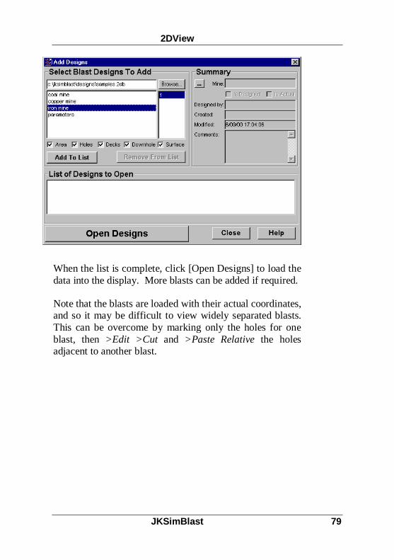
Select >File >Add Designs from the menu. Click the[Browse] button to open a database - other databases can beopened after each blast has been added to the list. Select ablast name from the list below, and then select the scenarioif more than one is available. Blast components within thea blast can be disabled via the check boxes. Summaryinformation from the selected blast is displayed on theright. To add a blast, click the [Add To List] button.Further blasts can be selected and added to the list, orremoved from the list if necessary.
2DView
JKSimBlast 79
When the list is complete, click [Open Designs] to load thedata into the display. More blasts can be added if required.
Note that the blasts are loaded with their actual coordinates,and so it may be difficult to view widely separated blasts.This can be overcome by marking only the holes for oneblast, then >Edit >Cut and >Paste Relative the holesadjacent to another blast.

2DView
80 JKSimBlast
Viewing a Blast2DView can display a blast from any direction. To set thedirection, select >View >Define. Also on the View menuare options to select the display of Marked or UnmarkedHoles, and the Options settings, which control the display(colour, visibility and style) of the blast objects, plus anindicator of the orientation of the grid with respect to thecurrent display (on the [Other] tab). Both the Holes andOptions settings can be activated at any time.
Define ViewDefine shows a dialog box for controlling the orientation ofthe display.
Viewing aBlast
Define View

2DView
JKSimBlast 81
Choose View
Several pre-defined views are provided in plan and section- select one these and then click [Apply]. User DefinedSurface displays the blast on an oblique projection. In allcases, the blast is projected onto a plane whose position andorientation is defined by the values on the tabs below. Planand section views are affected by the values shown on the[Centre] and [View Bounds] tabs; all tabs affect the UserDefined Surface view.
Centre
The centre of the display is defined by the east, north andlevel coordinates. To adjust the centre position:
move the blast by scrolling, Centre Design [End] orGoto;
centre the blast on an object [Home] - before changingthe view; or
enter new [Centre] coordinates.

2DView
82 JKSimBlast
View Bounds
This controls the amount of data that is displayed.Boundary planes are defined at a distance from each side ofthe projection plane - any objects found between theboundary planes are then displayed. The planes can beactivated or deactivated to display all objects by [click] onthe check box.
Angle From Centre
This represents a line from the current view centre to theviewer’s position. It is the opposite of the direction fromthe user to the centre position. Enter the bearing andincline (dip) angles and press [Enter] or [Apply] to changethe view, or [click] the dial arrows to change the angles by10° increments. The bearing will rotate continuouslythrough 360° and incline ranges from +90° to -90°.Changing the angles will also change the View Position.
View Position
This is the coordinate position of the user relative to thedisplay. Changing the coordinates will also change the[Angle From Centre].
Top Direction
This determines the orientation of the data around the[Centre] position. This can be applied automatically,where the program will create an appropriate view, or canbe applied manually. Unless a specific orientation isrequired, it is recommended to set the direction toautomatic.

2DView
JKSimBlast 83
Scroll BarsThe display can also be changed with the scroll bars belowand to the right of the window. In a plan or section view,hold down the [Shift] key and then [click] either end of thehorizontal scroll bar to rotate the display to the next view,or [click] the vertical scroll bar to switch from plan tosection view.
In User Defined Surface view, hold down the [Shift] keyand [click] the scroll bar to rotate the display around thecentre, as though rotating a sphere around its centre point.[Click] either side of a scroll bar to rotate by 45°, and[click] the arrow icon at the end of a scroll bar to rotate by1°; [drag] the scroll bar to change the angle by anintermediate amount.
Scroll Bars

2DView
84 JKSimBlast
Defining a View "Plane"When a view is defined, the data is projected onto thescreen from that orientation, in a plane parallel to thescreen and with the cursor located in the plane. The cursorcan be moved to any coordinate position within the plane.
To draw a region in a particular plane, the view must bedefined and the cursor positioned in that plane. Follow thesteps below to set up a "plane".
For a horizontal plane
in Define View, select a plan view
enter the required level on the [Centre] tab and click[Apply]
For a vertical section on grid (parallel to north-south oreast-west)
in Define View, select a section view
enter the required east or north coordinate in the Centretab and click [Apply]
For an inclined section (off grid)(note: these instructions can be applied to a bench, ring orface blast- alternatively, use a section view and adjust theinputs for Bearing and Incline accordingly)
in Define View, select a plan view
place the cursor at a location in the final plane - useGoTo to set the level, or [Home] to lock onto a holecollar
press [spacebar] to exit from the design area withoutmoving the cursor
turn on the anchor, and press [spacebar] to enter thedesign area
Defining aView “Plane”

2DView
JKSimBlast 85
use the mouse or GoTo (or [Home]) to place the cursorat another point in the plane - the line from the anchor tothe cursor will therefore be in the plane
note the bearing of the line from the anchor to the cursorin the status bar (east, north, level, bearing, dip,distance)
press [spacebar] to exit the Design Area
in Define View, select User Defined Surface
in [Centre], enter the coordinates of the cursor from thestatus bar (DO NOT click [Apply] yet)
select automatic in [Top Direction] (DO NOT click[Apply] yet)
in [Angle from Centre], enter the Bearing from thecursor position to your view position - this is equal tothe bearing from the anchor to the cursor plus or minus90 degrees
enter an Incline for a non-vertical view plane: 0 ishorizontal, 90 degrees is looking up, and -90 degrees islooking down
click [Apply]
The view plane is now parallel to the screen, and the cursorwill move within that plane.

2DView
86 JKSimBlast
PrintingThe display area can be printed as it appears, to scale, onany Windows-compatible printer. Select >File >PrintDesign Window from the menu. The printer can be setupeither from the Print dialog or from the Printer Setupoption. When completed, the configuration values can besaved and recalled for later use. The values are saved inthe file PrnConfigs.ini in the main JKSimBlast folder.
Click [Preview] at any time to view the print output on thescreen. Press [Esc] to return to the program. Displayoptions, such as object visibility or zoom scale, can bechanged while the Print dialog is active - just drag thedialog out of the way and make the changes.
Printing

2DView
JKSimBlast 87
Margin
This sets an extra margin around the page area, in additionto the non-printable area for the printer.
Annotation
This option controls the position of the logo and thecomment box. The size and contents of the comment boxare entered below. Note that the actual text is not savedwith the printer configuration. The logo is a bitmap filePrintLogo.bmp in the AuxFile folder - this can be replacedwith any suitable bitmap file.
Explosive Distribution
This controls the position of the explosive energydistribution scale on the page – [drag] the black rectangleto the required position.
ContourThis control operates in the same manner as the explosivedistribution control above.

2DView
88 JKSimBlast
Calculation RegionA calculation region is a bounded plane used in 2DView todefine a set of grid points for a contour or an explosiveenergy distribution. Values at the points are weighted bythe inverse of the distance from the blast data, such as holelength, detonation timing, explosive mass or energy, cost,etc.
In contouring, the selected value is applied to the entirelength of the hole to calculate the contours in a 2D plane.Therefore, in plan view, the value appears to be assigned tothe hole centre; in section view, the value appears as a linealong the length of the hole.
For an energy distribution, the explosive column is treatedas a series of infinitely small pieces of explosive, each withthe properties of the deck. The "contours" are calculated ina 2D plane but are weighted by the inverse of the square ofthe distance of the grid point in 3D from all explosivessurrounding it. The closer a grid point is to a piece ofexplosive, the higher the value. Therefore, points will havefairly constant values close to and along the length of adeck; and points between a group of holes or near thecentre of the blast will have higher values than pointsaround the outside of a blast.
The representation of a 2D contour is thus different from anenergy distribution, although the results appear to be thesame. For example, for evenly spaced holes in plan view(such as an open cut blast), a contour will appear the samefor calculation regions at the hole collars or toes. Anenergy distribution will be different for each regionbecause the concentration of explosive is higher at the toesthan at the collars, above the stemming.
The distance between points, or resolution of the grid,affects both the smoothness of the resulting contours and
CalculationRegion

2DView
JKSimBlast 89
the speed of calculation. While a higher resolution (morepoints) gives a smoother pattern, it will take longer tocalculate. A resolution between one quarter and one tenthof the distance between the blast holes will give anacceptable result in a short time, depending on the size ofthe blast. The resolution can then be fine tuned for furthercalculations.
Creating a Calculation RegionThere are two methods for creating a calculation region -from an existing polygon, or draw a new region. Thepolygon method is the easiest, and the region can then bemodified to adjust its position. This is most useful forcreating multiple regions parallel to the original designplane in a blast design module - the polygon must becreated in the design module. To create a region in adifferent plane, either draw a polygon in a design module,using GoTo to position the cursor, or set up a User DefinedSurface in 2DView and draw the region on that surface.
Regions used in 2DContour cannot be saved, and must berecreated each time. To save a region for futurecalculations, one solution is to create several polygons in adesign module and save these to separate scenarios - thesecan then be added to the current blast (/File > Add Design).Alternatively, regions used in Explosive EnergyDistribution can be saved to a database and recalled, withthe calculated values, for future display. Regions from anenergy distribution can also be used to calculate anddisplay a contour.
Polygon MethodTo create a region from a polygon, first draw a polygon in adesign module such as 2DBench or 2DRing, and save it ina blast database. Then, open or add the blast in 2DView.An alternative is to create a polygon and save or copy it asa text file of coordinate point values, and then import the
Creating aCalculationRegion
PolygonMethod

2DView
90 JKSimBlast
file as a string file or paste the string. Place the cursor nearthe polygon - use GoTo if it is difficult to select a particularpolygon from several in the blast.
In the Edit menu, select Make Region From NearestPolygon. This will create a region at the same position asthe polygon. A form will be displayed to enter a name forthe region, the separation between points (resolution) andthe specific gravity of the rock. The name can be used toidentify different regions. A resolution of about onequarter of the distance between blast holes will givereasonable results in minimum time, depending on the sizeof the region. The rock density is used in the energydistribution calculation.
The region can be removed at this stage by clicking[Cancel], or any region can be removed by placing thecursor near it and pressing [Backspace].
Multiple regions can be created from a single polygon, andthen modified (see below).
Draw a RegionA region can be drawn in the current view plane (seeDefining a View "Plane"). The drawing method is similarto a polygon, but allows sides to cross over.
To draw a region, [click] on the [Start…] button on thetoolbar. Place the cursor at the start position (note the east,north and level coordinates), [click] or press [Enter] for thefirst vertex, then move the cursor to the other vertices and
Draw a Region

2DView
JKSimBlast 91
[click] or press [Enter] again. GoTo, [Home] and the arrowkeys can be used to move the cursor.
The final step is to close the region form the last to the firstvertices. To close the region, [click] the [Close…] buttonon the toolbar or press [Esc].
After closing the region, in the form enter the name, pointseparation and rock density (see above).
The region can be removed at this stage by clicking[Cancel], or any region can be removed by placing thecursor near it and pressing [Backspace].
Modify RegionsAll of the data associated with a region can be modified.Select Modify Regions from the Edit menu. A formappears showing details of each region: name, pointseparation, rock density (Region Extra data), andcoordinates of each point (Region Points). The nearestregion to the cursor will be automatically selected, but anyregion available can be selected from the drop-down list.
ModifyRegions
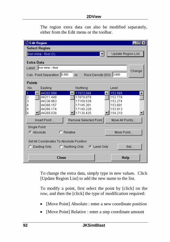
2DView
92 JKSimBlast
The region extra data can also be modified separately,either from the Edit menu or the toolbar.
To change the extra data, simply type in new values. Click[Update Region List] to add the new name to the list.
To modify a point, first select the point by [click] on therow, and then the [click] the type of modification required:
[Move Point] Absolute : enter a new coordinate position
[Move Point] Relative : enter a step coordinate amount

2DView
JKSimBlast 93
[Move All Points] : apply a step coordinate amount toall points simultaneously
[Remove Selected Point] : removes the point from theregion, to a minimum of three points
[Set] : sets all points to an absolute coordinate for east,north or level
Information on a region can be checked by placing thecursor near the region and clicking the [Query] button .The display will show the region name, specific gravity,resolution, perimeter length, area and number of points.

2DView
94 JKSimBlast
Explosive Energy DistributionThe Explosive Energy Distribution (EED) analysisproduces a contour of the concentration of explosive massor energy throughout the blast. The calculation isperformed on a 2D plane, defined by the user, but takinginto account the full three dimensional spread of theexplosives in the blast.
It is possible to calculate the three dimensional distributionof explosive energy around charged blast holes in much thesame way as electric potential fields can be determinedaround charged wires. Each column of charge is treated asa source of energy which spreads out with only geometricattenuation. The equations can be solved in terms ofenergy density or mass density to give results expressed inmegajoules per tonne of rock or the more commonkilograms per tonne of rock. Results are also given inmegajoules and kilograms per cubic metre, and megajoulesper square metre. The resultant contours of explosivedistribution are fully three dimensional and can be used asan effective design tool to determine burden and spacingvalues, to check for anomalous charging in a blast design,or to quantify fragmentation or damage in sections of ablast under local conditions.
It is a simple matter to set or alter any explosive's mass andenergy densities and to alter the rock density to suit everyapplication. The program calculates and displays thecontours in colour in any calculation region which can beinserted in or around the blast. The contour levels can beadjusted as can the resolution with which the final image isproduced. Calculation results can be saved to a databasefor later recall or used in other analyses.
An example of an explosive distribution analysis isprovided in the figures below. These show a wall in an
ExplosiveEnergyDistribution

2DView
JKSimBlast 95
open cut mine after removal of the blasted rock. Note thetraces of the blast holes in the central portion of the photo.The blast holes were charged with 2 metres of bulk ANFOat the bottom, with the remaining top 8 metres charged withdecoupled cartridges to reduce the overall energy. This hasresulted in high energy levels at the base of the blast andundercutting of the wall. Note also the damage in theupper section of the wall, caused by over charging of thetoes of the blast holes in the previous bench, similar to thisblast.
Starting a Distribution CalculationThe first step in starting an EED analysis is to create acalculation region in the required location. Some standardlocations for calculation regions are:
Starting aDistributionCalculation

2DView
96 JKSimBlast
collar, floor, toe or mid-charge level in a bench or faceblast;
in the section plane of the first, middle or last row orring in bench and ring blasts;
at the design location of the walls or new face aroundany type of blast.
The results of the analysis can then be compared visuallywith the blast performance at these locations, to helpquantify fragmentation, damage or overbreak.
Calculation Parameters
Marked / Unmarked Holes
This determines which holes are included in thecalculation. Check both boxes to use all holes in the blast.

2DView
JKSimBlast 97
Regions
Calculate for only the nearest region to the cursor, or for allregions. This is useful if several regions have been definedat different elevations or orientations (such as floor andwall regions).
Energy Distribution Type
3D assumes that all decks contribute equally to all points inthe region (static analysis), with the nearest decks havingthe greatest influence (geometric attenuation). 4D adds atiming effect to the 3D calculation to reduce the influenceof decks that detonate before or after the nearest deck to agrid point. The cooperation time is a characteristic of therock mass properties, and can be approximated to the firstburden movement time. See 4D Energy Distribution(below) for a more detailed explanation.
Store Results
The results of the calculation can be stored in a resultsdatabase or a temporary file, then one result set is recalledfor display. The results are stored more quickly in atemporary file, but a database offers long term storage thatcan be recalled at a later time, plus the results can be usedfor other purposes.
To store to a temporary file, ensure that the box isunchecked, and click [Continue...]. The results will bestored in the file "binary.tmp" in the "Results" folder. Thisfile will be overwritten whenever a new calculation isperformed.
To store in a database, check the box, click the browse [...]button and enter or select a database file, and select or entera new result name for the set of values. If a file nameextension is not specified for a new database, then ".eed"will be automatically added to the file name. Check the

2DView
98 JKSimBlast
[Remove...] box to ignore calculation results less than thevalue shown; this will reduce the amount of space requiredin the database. Click [Continue...] to calculate the values.
The display will show the grid points as their positions aredetermined, then the progress of the energy calculation andstorage (for a database) is shown. When this is completed,choose a result to display, modify model displayparameters if required, and activate the scale dialog tocontrol the range and colours (see below).
Displaying ResultsResults can be displayed in any view and, once saved, canbe recalled at any time, regardless of the current blast.However, only one result set can be displayed at a time.
DisplayingResults

2DView
JKSimBlast 99
Choosing Results
This step is necessary to replace any previous results still inmemory. Initially, the latest result will be automaticallyshown. Check the box to load the results from a database,select a database, and select the result set from thedatabase. If the box is left unchecked, then the results willbe recalled from the temporary file "Results\binary.tmp".Finally, select the initial units to be displayed.
Model ParametersThe model parameters are used to define how results aredisplayed. Usually, zero points should be ignored and datapoints are shown as filled rectangles. The last option is toindicate whether the holes should be redrawn after theresults have been displayed.
ScaleThe Scale dialog defines how the results are displayed.Values can be entered manually in any field, or the rangecan be equalised between the minimum and maximumvalues. Any range can be disabled by clearing the checkbox.
The Relative Area shows the percentage of the calculationarea occupied by each range. These values can be used tocompare results for different regions.
The displayed units can be selected from the list - standardunits are kilograms per tonne (kg/t), kilograms per cubicmetre (kg/m3), megaJoules per tonne (MJ/t), megaJoulesper cubic metre (MJ/m3), and megaJoules per square metre(MJ/m2).
The dialog can be reduced to the scale only, by [right-click]on the dialog and selecting Scale Only from the pop-up
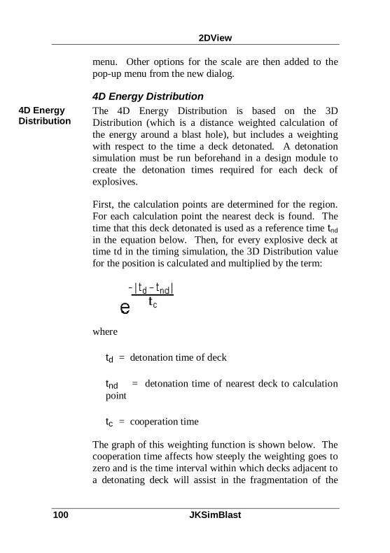
2DView
100 JKSimBlast
menu. Other options for the scale are then added to thepop-up menu from the new dialog.
4D Energy DistributionThe 4D Energy Distribution is based on the 3DDistribution (which is a distance weighted calculation ofthe energy around a blast hole), but includes a weightingwith respect to the time a deck detonated. A detonationsimulation must be run beforehand in a design module tocreate the detonation times required for each deck ofexplosives.
First, the calculation points are determined for the region.For each calculation point the nearest deck is found. Thetime that this deck detonated is used as a reference time tndin the equation below. Then, for every explosive deck attime td in the timing simulation, the 3D Distribution valuefor the position is calculated and multiplied by the term:
where
td = detonation time of deck
tnd = detonation time of nearest deck to calculationpoint
tc = cooperation time
The graph of this weighting function is shown below. Thecooperation time affects how steeply the weighting goes tozero and is the time interval within which decks adjacent toa detonating deck will assist in the fragmentation of the
4D EnergyDistribution

2DView
JKSimBlast 101
rock mass. After this time interval the interaction of decksreduces significantly due to the movement of the rockmass. The time is approximately the time to first burdenmovement and is very dependent on the rock mass.

2DView
102 JKSimBlast
2DContour2DContour is the hole contouring analysis module ofJKSimBlast. It allows the user to create contours of dataattached to blast holes, either as lines or filled regions. Theavailable contours include such values as detonation time,hole length, and total explosive mass and cost.
The program can also calculate contours of other user-defined data for a blasthole added to the blast database,such as drilling time, penetration rate, or water depth.
To create a contour, first load a blast, set the orientation ofthe view, then create a calculation region. Select the datato be contoured and start the calculation. To display theresults, set the scale and type of display.
A calculation region is used to create a set of grid points forcalculation of a contour. Values at the points are inverselyweighted by the distance from the blast data, such as holelength, detonation timing, explosive energy, cost ofdetonators, etc. Therefore, the closer the point is to a blasthole, the closer is its value to that of the blast hole. To
2DContour

2DView
JKSimBlast 103
calculate the contours, the selected value is applied to theentire length of the hole. In plan view, the value appears tobe assigned to the hole centre; in section view, the valueappears as a line along the length of the hole.
The distance between points, or resolution, affects both thesmoothness of the resulting contours and the speed ofcalculation. While a higher resolution (more points) givesa smoother pattern, it will take longer to calculate. Aresolution of about one quarter of the distance between theblast holes will give an acceptable result in a short time -the amount can then be fine tuned for the desired result.
Contour ControlThe contour control is used to select a value for contouringand the extent of influence of the data over the contourcalculation.
ContourControl

2DView
104 JKSimBlast
Contour Position With Value
Select a value from the drop-down list. The standardvalues are shown below. The units for the selected valueare shown on the right.
Grid InterpolationThe user can control which holes are included in thecalculation - tick both marked and unmarked for all holes.Interpolation shadowing is used to exclude holes from thecalculation from the opposite side of holes relative to thegrid points. The influence distance determines how manyholes are included in the calculation of a contour value at agrid point. To reduce the time of calculation, uncheck theinterpolation shadowing and set the influence distance to avalue just greater than the maximum distance from a pointto the surrounding holes (usually the burden or spacingdistance).
Current Contour Extents
This shows the maximum and minimum values for thecontours, based on the range of data values from the blastholes for the selected contour. Click [Reset Scale] toupdate the range if a different contour has been selected.
[Calculate Contour Surface for All Regions] starts thecontour calculation. The display will show the points inthe visible surface surfaces as the calculationprogresses.
[Remove All Contour Surfaces] deletes all contours.Use this if the regions have been modified or newvalues have been selected.
Values
The following standard values for contouring are calculatedfrom the blast data:

2DView
JKSimBlast 105
Actual Downhole Connection Length Used (m)Average Detonation Time (downhole) (ms)Charge Density (average) (kg/m³)Collar Easting (m)Collar Level (m)Collar Northing (m)Cost of Charges ($)Cost of Connections (downhole) ($)Cost of Delays (downhole) ($)Cost of Primers (downhole) ($)Cost of Stemming ($)Delay Actual Time (minimum downhole) (ms)Delay Nominal Time (minimum downhole) (ms)Delay Number (minimum downhole)Energy (total) (MJ)Hole Bearing (°)Hole Detonation OrderHole Detonation Time (minimum) (ms)Hole Diameter (mm)Hole Dip (°)Hole in Row NumberHole Length (m)Length Of Charge (total) (m)Length Of Stemming (total) (m)Mass Of Charge (total) (kg)Mass of Stemming (total) (kg)Nominal Detonation Time (downhole) (ms)RBS (average)Row NumberRWS (average)Stemming Density (average) (kg/m³)Supplied Length Of Connections (downhole) (m)Surface Delay Detonation (minimum) (ms)Toe Easting (m)Toe Level (m)Toe Northing (m)VOD (average) (m/s)

2DView
106 JKSimBlast
Contour ScaleThe contour scale is used to control the appearance of thedisplay - contour ranges, lines or fill, colours, and holes -and also shows the amount of the calculation regioncovered by each range.
The actual value of each contour range can be modified.For filled contours, a colour is assigned to values betweenthe minimum and maximum for each range - these can bechanged by entering a new value directly in the cell. For
Contour Scale

2DView
JKSimBlast 107
line contours, only the minimum value is used to determinethe contour.
To set equal ranges for the entire display, enter a minimumvalue for the first contour and a maximum value for the lastcontour. Click the [Equalise ...] button to set the ranges.The values can be greater than or less than the current blastextents. This can be useful for zooming in and showinggreater detail in a smaller range.
For filled squares, the percentage of the region areacovered by each colour is displayed on the right of thescale. The total area of the region can be shown in the[Query] dialog
To change the colour, place the mouse pointer over thecolour square and [double-click]. Select a new colour fromthe display.
The check next to each range determines whether thecontour is displayed.
Draw Holes After Contours will redisplay the blast holeson top of the contours.
The current contours can also be displayed from theContour menu - select Display All Contours.

2DView
108 JKSimBlast
Adding Custom Contour ValuesThe standard contours are calculated directly from the blastdata. However, other values can be added to the databaseand then displayed in the list of values and contoured. Thevalues must be in the form of a single value per blast hole.For example, the figure below shows the total amount ofsoft rock in each blast hole, where each metre of drillingwas classified as one of four rock types: soft, medium, hardand very hard. For each hole the total amount for each typewas then cumulated, and the four values added to the blastdatabase.
To create a custom contour, MS Access or another programto modify the Access databases is required. The data to becontoured will be added to the Holes table in the blastdatabase, but must also be described in the Extra Hole DataDefinition table. Follow these steps:
1. Open the database containing the blast.
AddingCustomContourValues
2DView
JKSimBlast 109
2. Open the Extra Hole Data Definition table. InMicrosoft Access, select the table and click [Open].Enter a name for each data value under Field Name,and a units of measurement for display under FieldUnits. The ID number will automatically update foreach record (row). The fields can be entered in anyorder.
3. Open the Holes table. In Microsoft Access, select thetable and click [Design]. Add a field (column) for eachof the data values in the Extra… table. The name ofeach field must be exactly the same as that entered inthe Extra… table.
4. Open the Holes table for data entry. In the View menu,select Datasheet. Enter the values for each hole underthe new columns. If the table contains more than oneset of hole data, check the Designs and Options tablesto determine which hole records belong to the relevantblast. The data can be copied and pasted as a columnof data from another application if properly organisedbeforehand, such as Microsoft Excel.
5. Close the Holes table, ensure that it has been saved andexit the program. Open the blast in 2DView, create aregion and check that the new data appears in the list ofvalues on the Contour Control. Select the contourvalue and continue as with standard values.

2DView
110 JKSimBlast

JKSimBlast 111
Ti me HE x
Overview
TimeHEx (Time vs Holes and Explosives) calculates themass of explosive or number of decks detonated within atime interval. As each deck is detonated, any decks afterthat time and within the time interval are cumulated for thatdetonation time. This is repeated for every deck to the endof the blast. The maximum value for the blast, known asthe Maximum Instantaneous Charge (MIC), is often used asa controlling factor when creating a blast design.
TimeHEx main window
The basic functions of TimeHEx are also included in thedesign modules of JKSimBlast, but the program providessome extended analyses. These are an adjustment for thearrival time of the detonation vibrations at a point ofinterest, and a cumulative plot of the bar chart that showsthe rate of explosive consumption in the blast.
Overview

TimeHEx
112 JKSimBlast
Maximum Instantaneous ChargeThe first step is to open a blast from a blast database. Adetonation simulation with a Monte Carlo analysis musthave been performed on the blast.
Open a blast from a JKSimBlast blast database. Select thedatabase, then the blast name and scenario. A detonationsimulation must have been calculated before the blast canbe opened in TimeHEx.
Reload the current blast. This allows the user to makemodifications in a design module and reload for analysiswith one click.
Save the data from the current chart to a text file. The datais formatted in tab separated columns, suitable for openingin a spreadsheet.
Print the current chart. The print layout can be modifiedfrom Print Preview.
Preview the chart for printing and modify the print layout.Note: [click] the Preview button again to return to the maindisplay.
Set the display options: colours, grid lines and hole size.To change a colour option, [double-click] the box. Theoptions can be saved and recalled as a scheme in the fileTimeHEx.ini. Multiple schemes can be created.
MaximumInstantaneousCharge

TimeHEx
JKSimBlast 113
Set the time interval for the current analysis calculation.Either select a time from 0 to 9 ms, or select "other" to dialany time from 0 to 1000 ms.
Show the design view, a plan of the current blast. Theview can optionally show grid lines, strings, text labels andsurface delays. The size and colour of blast holes aredefined in the display options.
Display the chart with charge mass on the vertical axis.
Display the chart with number of decks on the vertical axis.
Displays the bar values as cumulative mass or number ofdecks, with zero time interval. This shows the total amountdetonated up to any time in the blast.
Calculates the gradient (or slope) from the selected bar tothe previous bar. This is equivalent to the detonation rate,expressed as a mass or number of decks per millisecond.
Calculates the average gradient for an area of the chart.[Click] a bar for the start point, then [drag] sideways toselect an area. The result is equivalent to the rate ofaverage consumption for mass or number of decks permillisecond.
Select a point for calculation of the chart relative to a pointof interest. Either select a pre-defined text label, or enterthe coordinates for the point ("other"). The function usesthe detonation time plus the distance from each hole collar

TimeHEx
114 JKSimBlast
to the point of interest divided by the vibration velocitythrough the ground to calculate an arrival time for eachdeck at the point.
travel time (ms) = distance (m) x 1000 ÷ velocity (m/s)
arrival time (ms) = detonation time (ms) + travel time (ms)
The arrival time is then used instead of the detonation timeto recalculate the bar chart. To select a new point,[right-click] the button on the tool bar and [click] on a newpoint.
Set the wave transmission velocity through the rock, tocalculate the arrival time chart.
Enter the parameters for calculation of blast-inducedground vibration and airblast using the scaled-distanceformula. The calculation can be performed at a fixeddistance, or relative to a point of interest - either select apre-defined point (label) or enter the coordinates.
Display the ground vibration and airblast values for aselected bar in the chart. [Drag] to move the text to anotherlocation in the chart.
Query the values and data for a bar in the chart, or for ablast hole in the design view. In the chart, [click] on anybar to show a text box of the data. The arrow keys can thenbe used to move to the next bar, or [click] again to movethe cursor with the mouse.
In the design view, [click] any hole to see all data for thehole and a schematic display of the decks and downhole

TimeHEx
JKSimBlast 115
delays. The data in the text box can be copied and pasted ifrequired ([drag] across the text to select it, then[right-click] for the pop-up menu).
In the chart, find the holes in the design view associatedwith a bar. Place the cursor over a bar to highlight the barand show the linked blast holes. The holes are colouredaccording to their position in the chart relative to thehighlighted bar: holes that have "exploded" are to the leftof (before) the highlighted bar; "exploding" holes arelinked to the highlighted bar; and "unexploded" holes(after) are in the default colour. [Click] on a bar to use thearrow keys to move through the blast. (Note: select 0 mstime window, [click] on the first bar, and use the arrowkeys to "replay" the detonation simulation).
In the design view, find the bar in the chart for a hole. Thiswill be at the detonation time of the hole - note that the barmay include other holes.
Supplier, version and license information.
Activate on-line help.

TimeHEx
116 JKSimBlast
Design ViewThe Design View displays a plan of the current blast. Theview can optionally show grid lines, strings, text labels andsurface delays. The size and colour of objects in the vieware defined in the display options in the main chartwindow. The plan will automatically resize to fit thedesign view window. The status bar shows the coordinatesof the mouse pointer, the selected hole label and recordnumber, and the grid spacing.
Design View

TimeHEx
JKSimBlast 117
Toggle the visibility of grid lines.
Toggle the visibility of strings.
Toggle the visibility of surface delays.
Toggle the visibility of text labels.
Query the data for a blast hole. [Click] any hole to see alldata for the hole and a schematic display of the decks anddownhole delays. The data in the text box can be copiedand pasted if required ([drag] across the text to select it,then [right-click] for the pop-up menu).
Highlight the bar in the chart for a hole, corresponding tothe detonation time of the hole.
Activate on-line help.

TimeHEx
118 JKSimBlast