user guide - microsoft windows for driver release...
TRANSCRIPT

User Guide
ioDrive Product Family User Guide - Microsoft Windows
for Driver Release 3.1.5 English

ioMemory VSL 3.1.5
User Guide for MicrosoftWindows

ioMemory VSL 3.1.5 User Guide for Microsoft Windows | __________________ ___ ___ 2
ioMemory VSL 3.1.5 User Guide for Microsoft Windows . . . . . . . . . . . . . . . . . . . . . . . . . . . . . . . . . . . . . . . . . . . . . . 5
Introduction . . . . . . . . . . . . . . . . . . . . . . . . . . . . . . . . . . . . . . . . . . . . . . . . . . . . . . . . . . . . . . . . . . . . . . . . . . . . . . . . 6
About ioMemory Devices . . . . . . . . . . . . . . . . . . . . . . . . . . . . . . . . . . . . . . . . . . . . . . . . . . . . . . . . . . . . . . . . . . 6
About the ioMemory Virtual Storage Layer (VSL) . . . . . . . . . . . . . . . . . . . . . . . . . . . . . . . . . . . . . . . . . . . . . . 6
About Flashback Protection Technology . . . . . . . . . . . . . . . . . . . . . . . . . . . . . . . . . . . . . . . . . . . . . . . . . . . . . . 7
Software Installation . . . . . . . . . . . . . . . . . . . . . . . . . . . . . . . . . . . . . . . . . . . . . . . . . . . . . . . . . . . . . . . . . . . . . . . . . 8
New ioMemory VSL Installation . . . . . . . . . . . . . . . . . . . . . . . . . . . . . . . . . . . . . . . . . . . . . . . . . . . . . . . . . . . . 9
Existing ioMemory VSL Installation . . . . . . . . . . . . . . . . . . . . . . . . . . . . . . . . . . . . . . . . . . . . . . . . . . . . . . . . . . 10
Silent Install Option . . . . . . . . . . . . . . . . . . . . . . . . . . . . . . . . . . . . . . . . . . . . . . . . . . . . . . . . . . . . . . . . . . . . . . . 11
Outdated Firmware Check . . . . . . . . . . . . . . . . . . . . . . . . . . . . . . . . . . . . . . . . . . . . . . . . . . . . . . . . . . . . . . . . . 12
Enabling PCIe Power . . . . . . . . . . . . . . . . . . . . . . . . . . . . . . . . . . . . . . . . . . . . . . . . . . . . . . . . . . . . . . . . . . . . . 13
Device Naming . . . . . . . . . . . . . . . . . . . . . . . . . . . . . . . . . . . . . . . . . . . . . . . . . . . . . . . . . . . . . . . . . . . . . . . . . . 13
Adding a File System . . . . . . . . . . . . . . . . . . . . . . . . . . . . . . . . . . . . . . . . . . . . . . . . . . . . . . . . . . . . . . . . . . . . . . 14
Creating a RAID Configuration . . . . . . . . . . . . . . . . . . . . . . . . . . . . . . . . . . . . . . . . . . . . . . . . . . . . . . . . . . . . . 15
Using the Device as Swap . . . . . . . . . . . . . . . . . . . . . . . . . . . . . . . . . . . . . . . . . . . . . . . . . . . . . . . . . . . . . . . . . . 15
Understanding TRIM Support . . . . . . . . . . . . . . . . . . . . . . . . . . . . . . . . . . . . . . . . . . . . . . . . . . . . . . . . . . . . . . 16
Maintenance . . . . . . . . . . . . . . . . . . . . . . . . . . . . . . . . . . . . . . . . . . . . . . . . . . . . . . . . . . . . . . . . . . . . . . . . . . . . . . . . 18
Device LED Indicators . . . . . . . . . . . . . . . . . . . . . . . . . . . . . . . . . . . . . . . . . . . . . . . . . . . . . . . . . . . . . . . . . . . . 18
SNMP Support . . . . . . . . . . . . . . . . . . . . . . . . . . . . . . . . . . . . . . . . . . . . . . . . . . . . . . . . . . . . . . . . . . . . . . . . . . . 19
GUI Mangement . . . . . . . . . . . . . . . . . . . . . . . . . . . . . . . . . . . . . . . . . . . . . . . . . . . . . . . . . . . . . . . . . . . . . . . . . 19
Command-line Utilities . . . . . . . . . . . . . . . . . . . . . . . . . . . . . . . . . . . . . . . . . . . . . . . . . . . . . . . . . . . . . . . . . . . . 20
Enabling PCIe Power Override . . . . . . . . . . . . . . . . . . . . . . . . . . . . . . . . . . . . . . . . . . . . . . . . . . . . . . . . . . . . . 20
Uninstalling the ioMemory VSL . . . . . . . . . . . . . . . . . . . . . . . . . . . . . . . . . . . . . . . . . . . . . . . . . . . . . . . . . . . . . 23
Upgrading the ioMemory VSL- Non-RAID Configuration . . . . . . . . . . . . . . . . . . . . . . . . . . . . . . . . . . . . . . . 23
Upgrading the ioMemory VSL with a RAID Configuration . . . . . . . . . . . . . . . . . . . . . . . . . . . . . . . . . . . . . . . 24
Upgrading the Device Firmware . . . . . . . . . . . . . . . . . . . . . . . . . . . . . . . . . . . . . . . . . . . . . . . . . . . . . . . . . . . . . 25
Defragmentation . . . . . . . . . . . . . . . . . . . . . . . . . . . . . . . . . . . . . . . . . . . . . . . . . . . . . . . . . . . . . . . . . . . . . . . . . 26
Unmanaged Shutdown Issues . . . . . . . . . . . . . . . . . . . . . . . . . . . . . . . . . . . . . . . . . . . . . . . . . . . . . . . . . . . . . . . 26
Disabling Auto-Attach . . . . . . . . . . . . . . . . . . . . . . . . . . . . . . . . . . . . . . . . . . . . . . . . . . . . . . . . . . . . . . . . . . . . . 26
Enabling Auto-Attach . . . . . . . . . . . . . . . . . . . . . . . . . . . . . . . . . . . . . . . . . . . . . . . . . . . . . . . . . . . . . . . . . . . . . 27
Performance and Tuning . . . . . . . . . . . . . . . . . . . . . . . . . . . . . . . . . . . . . . . . . . . . . . . . . . . . . . . . . . . . . . . . . . . . . . 28
Disabling DVFS . . . . . . . . . . . . . . . . . . . . . . . . . . . . . . . . . . . . . . . . . . . . . . . . . . . . . . . . . . . . . . . . . . . . . . . . . . 28
Limiting APCI C-States . . . . . . . . . . . . . . . . . . . . . . . . . . . . . . . . . . . . . . . . . . . . . . . . . . . . . . . . . . . . . . . . . . . . 28
Setting NUMA Affinity . . . . . . . . . . . . . . . . . . . . . . . . . . . . . . . . . . . . . . . . . . . . . . . . . . . . . . . . . . . . . . . . . . . . 29
Setting the Interrupt Handler Affinity . . . . . . . . . . . . . . . . . . . . . . . . . . . . . . . . . . . . . . . . . . . . . . . . . . . . . . . . 29
Appendix A- Troubleshooting Event Log Messages . . . . . . . . . . . . . . . . . . . . . . . . . . . . . . . . . . . . . . . . . . . . . . . . 30

ioMemory VSL 3.1.5 User Guide for Microsoft Windows | __________________ ___ ___ 3
Appendix B- Manual Installation . . . . . . . . . . . . . . . . . . . . . . . . . . . . . . . . . . . . . . . . . . . . . . . . . . . . . . . . . . . . . . . 32
Manual Installation on Windows Server 2003 . . . . . . . . . . . . . . . . . . . . . . . . . . . . . . . . . . . . . . . . . . . . . . . . . . 32
Manual Install on Windows Server 2008 . . . . . . . . . . . . . . . . . . . . . . . . . . . . . . . . . . . . . . . . . . . . . . . . . . . . . . 41
Appendix C- Command-line Utilities . . . . . . . . . . . . . . . . . . . . . . . . . . . . . . . . . . . . . . . . . . . . . . . . . . . . . . . . . . . . 44
fio-attach . . . . . . . . . . . . . . . . . . . . . . . . . . . . . . . . . . . . . . . . . . . . . . . . . . . . . . . . . . . . . . . . . . . . . . . . . . . . . . . . 45
fio-beacon . . . . . . . . . . . . . . . . . . . . . . . . . . . . . . . . . . . . . . . . . . . . . . . . . . . . . . . . . . . . . . . . . . . . . . . . . . . . . . . 45
fio-bugreport . . . . . . . . . . . . . . . . . . . . . . . . . . . . . . . . . . . . . . . . . . . . . . . . . . . . . . . . . . . . . . . . . . . . . . . . . . . . 46
fio-config . . . . . . . . . . . . . . . . . . . . . . . . . . . . . . . . . . . . . . . . . . . . . . . . . . . . . . . . . . . . . . . . . . . . . . . . . . . . . . . 47
fio-detach . . . . . . . . . . . . . . . . . . . . . . . . . . . . . . . . . . . . . . . . . . . . . . . . . . . . . . . . . . . . . . . . . . . . . . . . . . . . . . . 49
fio-format . . . . . . . . . . . . . . . . . . . . . . . . . . . . . . . . . . . . . . . . . . . . . . . . . . . . . . . . . . . . . . . . . . . . . . . . . . . . . . . 50
fio-pci-check . . . . . . . . . . . . . . . . . . . . . . . . . . . . . . . . . . . . . . . . . . . . . . . . . . . . . . . . . . . . . . . . . . . . . . . . . . . . . 52
fio-status . . . . . . . . . . . . . . . . . . . . . . . . . . . . . . . . . . . . . . . . . . . . . . . . . . . . . . . . . . . . . . . . . . . . . . . . . . . . . . . . 53
fio-sure-erase . . . . . . . . . . . . . . . . . . . . . . . . . . . . . . . . . . . . . . . . . . . . . . . . . . . . . . . . . . . . . . . . . . . . . . . . . . . . 56
fio-trim-config . . . . . . . . . . . . . . . . . . . . . . . . . . . . . . . . . . . . . . . . . . . . . . . . . . . . . . . . . . . . . . . . . . . . . . . . . . . 58
fio-update-iodrive . . . . . . . . . . . . . . . . . . . . . . . . . . . . . . . . . . . . . . . . . . . . . . . . . . . . . . . . . . . . . . . . . . . . . . . . . 59
Appendix D- TRIM Support . . . . . . . . . . . . . . . . . . . . . . . . . . . . . . . . . . . . . . . . . . . . . . . . . . . . . . . . . . . . . . . . . . . 61
Platforms . . . . . . . . . . . . . . . . . . . . . . . . . . . . . . . . . . . . . . . . . . . . . . . . . . . . . . . . . . . . . . . . . . . . . . . . . . . . . . . 61
Using the TRIM Service . . . . . . . . . . . . . . . . . . . . . . . . . . . . . . . . . . . . . . . . . . . . . . . . . . . . . . . . . . . . . . . . . . . 61
Configurations . . . . . . . . . . . . . . . . . . . . . . . . . . . . . . . . . . . . . . . . . . . . . . . . . . . . . . . . . . . . . . . . . . . . . . . . . . . 63
Appendix E- Monitoring the Health of ioMemory Devices . . . . . . . . . . . . . . . . . . . . . . . . . . . . . . . . . . . . . . . . . . 64
NAND Flash and Component Failure . . . . . . . . . . . . . . . . . . . . . . . . . . . . . . . . . . . . . . . . . . . . . . . . . . . . . . . . 64
Health Metrics . . . . . . . . . . . . . . . . . . . . . . . . . . . . . . . . . . . . . . . . . . . . . . . . . . . . . . . . . . . . . . . . . . . . . . . . . . . 64
Health Monitoring Techniques . . . . . . . . . . . . . . . . . . . . . . . . . . . . . . . . . . . . . . . . . . . . . . . . . . . . . . . . . . . . . . 65
Software RAID and Health Monitoring . . . . . . . . . . . . . . . . . . . . . . . . . . . . . . . . . . . . . . . . . . . . . . . . . . . . . . . 65
Appendix F- Using Windows Page Files with the ioMemory Devices . . . . . . . . . . . . . . . . . . . . . . . . . . . . . . . . . . 67
Configuring Device Paging Support . . . . . . . . . . . . . . . . . . . . . . . . . . . . . . . . . . . . . . . . . . . . . . . . . . . . . . . . . . 67
Windows Page File Management . . . . . . . . . . . . . . . . . . . . . . . . . . . . . . . . . . . . . . . . . . . . . . . . . . . . . . . . . . . . 69
Performance . . . . . . . . . . . . . . . . . . . . . . . . . . . . . . . . . . . . . . . . . . . . . . . . . . . . . . . . . . . . . . . . . . . . . . . . . . . . . 73
Appendix G- SNMP Test Mode and MIB Support . . . . . . . . . . . . . . . . . . . . . . . . . . . . . . . . . . . . . . . . . . . . . . . . . 74
Using Test-Mode Registry Values . . . . . . . . . . . . . . . . . . . . . . . . . . . . . . . . . . . . . . . . . . . . . . . . . . . . . . . . . . . . 74
SNMP MIB Support . . . . . . . . . . . . . . . . . . . . . . . . . . . . . . . . . . . . . . . . . . . . . . . . . . . . . . . . . . . . . . . . . . . . . . 77
Appendix H- SMI-S Interface . . . . . . . . . . . . . . . . . . . . . . . . . . . . . . . . . . . . . . . . . . . . . . . . . . . . . . . . . . . . . . . . . . 79
Installing the SMI-S WMI Provider on Windows . . . . . . . . . . . . . . . . . . . . . . . . . . . . . . . . . . . . . . . . . . . . . . . 80
Verifying SMI-S Installation on Windows . . . . . . . . . . . . . . . . . . . . . . . . . . . . . . . . . . . . . . . . . . . . . . . . . . . . . 80
Description . . . . . . . . . . . . . . . . . . . . . . . . . . . . . . . . . . . . . . . . . . . . . . . . . . . . . . . . . . . . . . . . . . . . . . . . . . . . . . 85
Implementation . . . . . . . . . . . . . . . . . . . . . . . . . . . . . . . . . . . . . . . . . . . . . . . . . . . . . . . . . . . . . . . . . . . . . . . . . . 87

ioMemory VSL 3.1.5 User Guide for Microsoft Windows | __________________ ___ ___ 4
Indications . . . . . . . . . . . . . . . . . . . . . . . . . . . . . . . . . . . . . . . . . . . . . . . . . . . . . . . . . . . . . . . . . . . . . . . . . . . . . . 93
Appendix I- NUMA Configuration . . . . . . . . . . . . . . . . . . . . . . . . . . . . . . . . . . . . . . . . . . . . . . . . . . . . . . . . . . . . . 98
Appendix J- Upgrading Devices from VSL 2.x to 3.x . . . . . . . . . . . . . . . . . . . . . . . . . . . . . . . . . . . . . . . . . . . . . . . 102
Upgrade Procedure . . . . . . . . . . . . . . . . . . . . . . . . . . . . . . . . . . . . . . . . . . . . . . . . . . . . . . . . . . . . . . . . . . . . . . . 102
Appendix K- Documentation Permissions . . . . . . . . . . . . . . . . . . . . . . . . . . . . . . . . . . . . . . . . . . . . . . . . . . . . . . . 106
AVR Bootloader . . . . . . . . . . . . . . . . . . . . . . . . . . . . . . . . . . . . . . . . . . . . . . . . . . . . . . . . . . . . . . . . . . . . . . . . . . 106
tree.h . . . . . . . . . . . . . . . . . . . . . . . . . . . . . . . . . . . . . . . . . . . . . . . . . . . . . . . . . . . . . . . . . . . . . . . . . . . . . . . . . . . 106
Fusion Powered Support . . . . . . . . . . . . . . . . . . . . . . . . . . . . . . . . . . . . . . . . . . . . . . . . . . . . . . . . . . . . . . . . . . . . . . 108

ioMemory VSL 3.1.5 User Guide for Microsoft Windows | __________________ ___ ___ 5
ioMemory VSL 3.1.5 User Guide for Microsoft Windows
Legal Notices
The information contained in this document is subject to change without notice.
Copyright © 2012 Fusion-io, Inc. All rights reserved.
Fusion-io, the Fusion-io logo, ioMemory, Virtual Storage Layer, and ioDrive are registered trademarks, and VSL, ioFX,
Flashback, and Flashback Protection are trademarks of Fusion-io, Inc. in the United States and other countries.
The names of other organizations and products referenced herein are the trademarks or service marks (as applicable)
of their respective owners. Unless otherwise stated herein, no association with any other organization or product
referenced herein is intended or should be inferred.
You may not use the ioMemory VSL software for any competitive benchmarking purpose without prior written
consent from Fusion-io. You may not publish any performance data related to the ioMemory VSL software without
prior written consent from Fusion-io.
Fusion-io
2855 E. Cottonwood Parkway, Box 100
Salt Lake City, UT 84121
USA
(801) 424-5500
Part Number: D0001658-016_2
: June 21, 2012Published

ioMemory VSL 3.1.5 User Guide for Microsoft Windows | __________________ ___ ___ 6
Introduction
Overview
Congratulations on your purchase of a Fusion-io® solid-state storage device. This guide explains how to install,
troubleshoot, and maintain the software for your ioMemory devices.
Throughout this manual, when you see a reference to an , you may substitute your particularioMemory device
device(s), such as an ioDrive2 device, ioFX device, or each of the two ioMemory devices of an ioDrive Duo
device.
Products with Multiple Devices
Some products, such as an ioDrive Duo device, are actually comprised of . If yourmultiple ioMemory devices
product consists of multiple ioMemory devices, you will manage each ioMemory device as an independent device.
For example, if you have an ioDrive Duo device, you can independently attach, detach, and/or format each of the
two ioMemory devices. Each of the two devices will be presented as an individual device to your system.
About ioMemory Devices
Designed around a revolutionary silicon-based storage architecture, ioMemory devices are the world's most advanced
NAND flash storage devices, with performance comparable to DRAM and storage capacity on par with today's hard
disks – giving you the power to improve storage performance by orders of magnitude. ioMemory devices allow every
computer to exceed the I/O performance of an enterprise SAN.
ioMemory devices are data accelerators designed specifically to improve the bandwidth for I/O-bound applications.
They are no-compromise solutions for the toughest computational challenges faced by data centers today, putting
them in a league of their own.
About the ioMemory Virtual Storage Layer (VSL)
More than just a hardware driver, the ioMemory® Virtual Storage Layer® (VSL™) is the "secret sauce" that gives
ioMemory devices their amazing performance. The VSL™ is a hybrid of the RAM virtualization subsystem and the
disk I/O subsystem, combining the best of both worlds. It appears like a disk to interface well with block-based
applications and software. At the same time, it runs like RAM underneath to maximize performance. This provides the
following game-changing benefits:

ioMemory VSL 3.1.5 User Guide for Microsoft Windows | __________________ ___ ___ 7
Performance: The VSL offers direct and parallel access to multiple CPU cores, enabling near-linear
performance scaling, consistent performance across different read/write workloads, and low latency with
minimal interrupts and context switching
Extensibility: The VSL enables flash-optimized software development, making each ioMemory module a
flexible building block for building a flash-optimized data center.
Flash: Not Just Another Disk Drive
Whether on a PCIe card or in a drive bay, other SSD providers besides Fusion-io simply treat flash as another disk
drive, putting it behind RAID controllers. This approach has the following limitations:
Reduced performance and reliability
Increased latency and complexity
Limited potential for software development and optimization around the flash storage medium
With the ioMemory VSL, ioMemory devices avoid this limiting approach and provide a wealth of performance and
optimization possibilities.
About Flashback Protection Technology
Like many other memory devices, NAND flash eventually fails with use. Those failures can be either permanent or
temporary. Fusion's Flashback™ redundancy is designed to address those ioMemory chips that experience permanent
failures, and provides additional protection above and beyond ECC (Error Correction Code) for soft failures.
Flashback technology provides a real-time RAID-like redundancy at the chip-level, without sacrificing user capacity or
performance for fault tolerance. Solutions that use physical RAID schemes for redundancy/protection must in general
either sacrifice capacity (RAID 1), or performance (RAID 5).
Fusion’s Flashback Protection™ technology, with self-healing properties, ensures higher performance, minimal failure,
and longer endurance than all other flash solutions.

ioMemory VSL 3.1.5 User Guide for Microsoft Windows | __________________ ___ ___ 8
1.
2.
1.
2.
Software InstallationBefore continuing with the installation of this software, please read the following:
Ensure that your operating system is included in the list of contained in the supported operating systems
for this release.ioMemory VSL Release Notes
Before installing the ioMemory VSL, make sure you have properly installed the ioMemory device(s). Refer to
the for full details and hardware requirements.ioMemory Hardware Installation Guide
Every ioDrive device in a system running ioMemory VSL 3.1.x or later must be upgraded to the latest version of
the firmware.
For example, if you have a system running ioMemory VSL 2.3.1 with ioDrive devices previously installed, and you
want to install new ioDrive2 devices (that require the latest version of the firmware), then you will need to
upgrade all of the existing devices to the latest firmware version.
Upgrade Previous Devices First
If you have ioDrive devices configured for ioMemory VSL 2.x or earlier, you must upgrade their firmware before
installing new devices in the system. See for the upgradeAppendix J- Upgrading Devices from VSL 2.x to 3.x
instructions.
Installation Overview
If you are installing this version of ioMemory VSL on a system with ioDrive devices configured for VSL 2.x,
you must carefully follow the instructions in the section.Appendix J- Upgrading Devices from VSL 2.x to 3.x
If you do not need to upgrade devices to the firmware for VSL 3.x.x, but your system does have previous
versions of the ioMemory VSL installed, you will need to uninstall the ioMemory VSL software. See the
section for instructions. Once you have uninstalled the software,Existing ioMemory VSL Installation
continue with the instructions on that page.
Install the latest version of the ioMemory VSL.
For information on capturing an installation log for troubleshooting purposes, see the following Microsoft
.KB article

ioMemory VSL 3.1.5 User Guide for Microsoft Windows | __________________ ___ ___ 9
3.
4.
1.
2.
3.
4.
5.
6.
7.
8.
9.
Upgrade the Firmware to the latest version, if needed (recommended). This applies to ioDrive2 devices that
may use a version of the firmware that is earlier than the latest version.
Configure the device(s) by , , etc.Adding a File System Creating a RAID Configuration
New ioMemory VSL Installation
To install the ioMemory VSL software on a new system:
Complete all the installation steps given in the .Hardware Installation Guide
Log into your computer with an account that has Administrative rights.
Download the Windows ioMemory VSL installation program from http://ts.fujitsu.com/support/
and save it to your desktop or another convenient directory.
Run the ioMemory VSL installation program. The installation program presents a custom setup tree-view with
options for installation.
Select a type of install by selecting components from the drop-down menus. If you change your mind later, you
can use the Repair option in Programs and Features, or Add or Remove Programs in the Control Panel.
Click on each component to view its description. The descriptions will appear to the right of the install
tree.
Click .Next
To select a different folder for the installation, browse to the folder and click . The default folder is OK
.C:\Program Files\Fusion-io ioMemory VSL
Follow the onscreen prompts to complete the install.
Choose on the finish screen of the installer.Finish
You should be prompted to reboot your system to complete the installation process. If you are not prompted to
reboot, you should still reboot your system after completing the installation. If Windows does not recognize the
ioMemory device(s) after rebooting, you may need to manually install the ioMemory VSL for the device(s). See
for information on manual installation.Appendix B- Manual Installation
The installation program:
Creates a folder for the software components (the default path is C:\Program Files\Fusion-io).ioMemory VSL
Installs and loads the ioMemory VSL. (This may require a restart.)
Installs support for SNMP (if installed, and if Microsoft SNMP is installed and the SNMP service is running).
Creates a folder for the VSL utilites. The default path is C:\Program Files\Common Files\VSL Utils

ioMemory VSL 3.1.5 User Guide for Microsoft Windows | __________________ ___ ___ 10
1.
2.
3.
4.
5.
6.
When the install program creates the ioMemory VSL folder on the drive, it also creates these sub-folders:
<VSL-version>\Driver —for manual installations using Device Manager
Firmware —contains the latest ioMemory device firmware
SNMP —contains the SNMP components
SMIS and SDK —if selected for installation
ioSphere is a free browser-based software for managing ioMemory devices. It is also available from
http://ts.fujitsu.com/support/ , but is in a different location than the ioMemory VSL packages and documentation.
Proceed to the to continue.Outdated Firmware Check
Existing ioMemory VSL Installation
Do not install new ioDrive2 devices with previously installed ioDrive devices without first completing the
instructions in .Appendix J- Upgrading Devices from VSL 2.x to 3.x
To install the latest ioMemory VSL Windows software on an existing installation,
Review the Release Notes file available for this version of the software for additional steps that may be needed
to complete the install.
Log in as Administrator or have Administrator rights.
Uninstall the existing VSL, utilities, etc., using , or Programs and Features Add or Remove Programs
(depending on your version of Windows), in the .Control Panel
Restart the computer.
The ioMemory VSL installation program will attempt to remove previous versions of the software,
however if it fails and a previous version is removed by the user after the newest version is installed, the
ioMemory VSL will no longer load after a restart. In that case, you need to a) run the Repair option in the
installation program, from (or ) in the ControlPrograms and Features Add or Remove Programs
Panel, and b) restart the computer.
Download the VSL installation program for Windows from http://ts.fujitsu.com/support/ to your desktop or a
convenient directory.
Run the ioMemory VSL installation program. The installation program presents a custom setup tree-view with
options for installation.
ioMemory VSL 3.1.5 User Guide for Microsoft Windows | __________________ ___ ___ 11
7.
8.
9.
10.
11.
Select a type of install by selecting components from the drop-down menus. If you change your mind later, you
can use the Repair option in Programs and Features, or Add or Remove Programs in the Control Panel.
Click on each component to view its description. The descriptions will appear to the right of the install
tree.
Click .Next
To select a different folder for the installation, browse to the folder and click . The default folder is OK
.C:\Program Files\Fusion-io ioMemory VSLThe installer also creates a folder for the VSL utilites. The default path is C:\ProgramFiles\Common Files\VSL Utils
Follow the onscreen prompts to complete the install.
Choose on the finish screen of the installer.Finish
You should be prompted to reboot your system to complete the installation process. If you are not prompted to
reboot, you should still reboot your system after completing the installation. If Windows does not recognize the
ioMemory device(s) after rebooting, you may need to manually install the ioMemory VSL for the device(s). See
for information on manual installation.Appendix B- Manual Installation
ioSphere is a free browser-based software for managing ioMemory devices. It is also available from
http://ts.fujitsu.com/support/, but is in a different location than the ioMemory VSL packages and documentation.
Once the system restarts, proceed to the section to continue.Outdated Firmware Check
Silent Install Option
Uninstall Previous
If the you have a version of the ioMemory VSL previously installed, you must uninstall it first (see the information
on a below). You can must manually reboot the computer after installing the new version withSilent Uninstall
the silent install option. This step must be performed prior using any ioMemory VSL utilities or functionality.
If you are installing remotely or with scripts, you can use the silent install option ( ) when you run the/quietinstallation program in the command-line interface.
In the command-line interface, navigate to the folder that contains the installer file, and run this command:.exe
<installname>.exe /quiet
Where the is the name of the installer file.<installname>.exe

ioMemory VSL 3.1.5 User Guide for Microsoft Windows | __________________ ___ ___ 12
1.
2.
1.
2.
3.
This option installs the ioMemory VSL using its default settings, eliminating the need to "click Next" or select settings
during install.
Installing Components
The default command-line installation installs the ioMemory VSL (including the command-line utilities) and the
firmware file. You can add additional components using the following command:
<installname>.exe /quiet ADDLOCAL=SNMP,SDK,SMIS
Remove any component (and leading/trailing comma) that you do not wish to install.
Silent Uninstall
You may silently uninstall the ioMemory VSL with this command:
<installname>.exe /uninstall /quiet
Outdated Firmware Check
Check Using the Command-line Interface
More information on these command-line utilities is available in .Appendix C- Command-line Utilities
Run and examine the output.fio-statusIf any device is in minimal mode, then the firmware is outdated.
If the firmware listed for any device is a lower number than the latest firmware version as noted in the
Release Notes, then the firmware is old, but not outdated.
If the firmware is old or outdated, update it using the utility.fio-update-iodrive
Check using the Optional GUI Interface
You can use the (optional) ioSphere GUI program to check for outdated firmware.
To check for outdated or old firmware:
Launch the ioSphere and look for any devices that have a warning symbol.
Click on any devices with a warning symbol to ensure that the alert is from outdated firmware.
Select all devices requiring firmware update and use the ioSphere to update the firmware. Refer to the ioSphere
User Guide for details.

ioMemory VSL 3.1.5 User Guide for Microsoft Windows | __________________ ___ ___ 13
1.
2.
3.
To check for old but not outdated firmware:
Find the name of the latest firmware version as noted in the Release Notes.
Use the ioSphere to check each ioMemory device's firmware version against the latest.
Refer to the ioSphere User Guide for instructions on how to update the firmware.
Enabling PCIe Power
If you have installed any dual ioMemory devices, such as the ioDrive2 Duo device, then the device may require
additional power to properly function (beyond the minimum 25W provided by PCIe Gen2 slots).
Additional power may be provided through a power cable (see the ) or through theioMemory Hardware Installation Guide
PCIe slot(s). For instructions on allowing the device to draw additional power from the PCIe slot(s), see Enabling
in the Maintenance section.PCIe Power Override

ioMemory VSL 3.1.5 User Guide for Microsoft Windows | __________________ ___ ___ 14
1.
2.
3.
Device NamingThe ioMemory device receives a name and number as part of the install process for identification. The syntax is fctxwhere x is the number of the PCIe bus where you installed the ioDrive. Use ioManager to view this bus number, or
follow these steps:
Choose > > > > .Start Control Panel System Hardware Device Manager
Select .Fusion ioMemory VSL devices
Click on your ioMemory device in the list. The Properties dialog box appears.
The Location field shows the PCIe bus number for your device ( in this case).fct9
The system manufacturer assigns bus numbers, which can range from 0 on up. These numbers may or may not
reflect the physical location of the bus. (For example, the second slot from the edge of the motherboard may be
Bus 2, but it could also be Bus 16 or another arbitrary number. Checking Device Manager is one way to confirm
the specific bus number for your installation. You can also use ioManager to view this number as well.)

ioMemory VSL 3.1.5 User Guide for Microsoft Windows | __________________ ___ ___ 15
1.
2.
3.
4.
5.
6.
Adding a File System
With ioMemory device(s) and ioMemory VSL installed, you can now use the Windows Disk Management utility to
make your device available to applications. Typically, Windows detects the new device, initializes it, and displays it in
Disk Management. You can then add partitions, format a volume, or create a RAID configuration on your ioMemory
device using the standard Windows procedures (see the documentation for moreWindows Disk Management Utility
details).
If Windows does not initialize the device, you can do so manually. To initialize an ioMemory device,
Select > .Start Control Panel
Click .Administrative Tools
Click .Computer Management
Click in the Storage section of the console tree.Disk Management
Locate and right-click the ioMemory device in the list of storage devices on the right. (If the ioMemory device
does not appear in the list, choose from the Action menu. You may also need to restart yourRescan Disks
computer to display the ioMemory device in the list.)
Click .Initialize Disk
You can now use the Disk Management Utility to add a file system to your ioMemory device.
Creating a RAID Configuration
You can use your ioMemory device as part of a RAID configuration with one or more additional ioMemory devices.
To do so, you must format your ioMemory devices as dynamic volumes. In turn, you can then use these dynamic
volumes to create multi-disk RAID configurations (spanned, striped, mirrored, or RAID 5).
For specific steps to perform a RAID configuration, see the Windows Disk Management Utility documentation for
details.
If you are using RAID1/Mirroring and one device fails, be sure to run a fio-format on the replacement device
(not the remaining good device) before rebuilding the RAID.
Using the Device as Swap
To safely use the ioMemory device as swap space, you need to use the utility to pass a specialfio-configpre-allocation parameter.

ioMemory VSL 3.1.5 User Guide for Microsoft Windows | __________________ ___ ___ 16
For example:
fio-config -p FIO_PREALLOCATE_MEMORY 1072,4997,6710,10345
Where 1072,4997,6710,10345 are device serial numbers obtained from (do not use adapter serialfio-statusnumbers).
A 4K sector size format is required for swap—this reduces the software memory footprint to reasonable levels. See the
utility for information on changing the device sector sizes.fio-format
Be sure to provide the serial numbers for the ioMemory device, not the adapter.
FIO_PREALLOCATE_MEMORY is necessary to have the device usable as swap space. This will ensure the device
is crash-free during operation. See Appendix I- fio-config Options for more information on setting this
parameter.
You must have enough RAM available to enable the ioMemory device with pre-allocation enabled for use as
swap. Attaching an ioMemory device, with pre-allocation enabled, without sufficient RAM may result in the loss
of user processes and system instability.
Consult the for RAM requirements with this version of the ioMemory VSL.Release Notes
The parameter is recognized by the ioMemory VSL at load time, but theFIO_PREALLOCATE_MEMORYrequested memory is not actually allocated until the specified device is attached.
Understanding TRIM Support
With this version of the ioMemory VSL, TRIM (also known as Discard) is enabled by default on many operating
systems.
TRIM addresses an issue unique to solid-state storage. When a user deletes a file, the device does not recognize that it
can reclaim the space. Instead the device assumes the data is valid.
TRIM is a feature on newer operating systems. It informs the device of logical sectors that no longer contain valid user
data. This allows the wear-leveling software to reclaim that space (as reserve) to handle future write operations.
For a complete description of TRIM support on Windows, see the appendix.TRIM Support
Windows does not support TRIM with a RAID 5 configuration.

ioMemory VSL 3.1.5 User Guide for Microsoft Windows | __________________ ___ ___ 17
TRIM on Windows Server 2008 R2
Windows Server 2008 R2 has built-in TRIM support. With this operating system, ioMemory devices work with
Windows TRIM commands by default.
TRIM on Windows Server 2003 and Windows Server 2008 R1
Windows TRIM is not built into Windows Server 2003 or Windows Server 2008 R1. However, the Fusion-io TRIM
service is installed with the Windows ioMemory VSL and it provides the necessary TRIM operations.
The Fusion-io TRIM service is enabled by default, unless it detects an operating system that supports TRIM (such as
Windows Server 2008 R2). You can disable the Fusion-io TRIM service by using the utility. See fio-trim-config for more details.fio-trim-config

ioMemory VSL 3.1.5 User Guide for Microsoft Windows | __________________ ___ ___ 18
MaintenanceThe ioMemory VSL includes software utilities for maintaining the device. You can also install SNMP as a monitoring
option.
Device LED Indicators
The ioMemory device includes three LEDs showing drive activity or error conditions. The LEDs on your device
should be similar to one of these configurations:

ioMemory VSL 3.1.5 User Guide for Microsoft Windows | __________________ ___ ___ 19
This table explains the information that these LEDs convey:
ioFX devices have an additional LED that illuminates the ioFX logo. This LED has no functional significance and
it cannot be turned off.
SNMP Support
The ioMemory VSL Windows Setup program provides the option to install support for SNMP. If you choose this
option, the Setup program installs the components and modifies the Registry for this support. You must also have the
Microsoft Windows SNMP Service installed and running on the computer to receive reports.
Once you run the VSL Windows Setup program, it will stop and start the Windows SNMP Service to recognize the
VSL's agent.
If you did not choose to install the SNMP support at Setup, and want to do so later, rerun the Setup program. Choose
to install only the SNMP support from the list of items. Once the Setup program completes the install, it will stop and
restart the Windows SNMP Service.
For details on using SNMP Test Mode, see .Appendix G- SNMP Test Mode and MIB Support
GUI Mangement
ioSphere is a free browser-based solution for managing ioMemory devices. It is also available from
http://ts.fujitsu.com/support/, but it is located in a different download location along with documentation.
ioMemory VSL 3.1.5 User Guide for Microsoft Windows | __________________ ___ ___ 20
The ioSphere can perform:
Firmware upgrades
Low-level formatting
Attach and detach actions
Device status and performance information
Command-line UtilitiesThe Windows Setup package also includes several command-line utilities for managing your
http://ts.fujitsu.com/support/:
fio-attach
fio-beacon
fio-bugreport
fio-config
fio-detach
fio-format
fio-pci-check
fio-status
fio-sure-erase
fio-trim-config
fio-update-iodrive
Each of these is described in detail in .Appendix C- Command-line Utilities
Enabling PCIe Power Override
If you have installed any products with multiple ioMemory devices, such as the ioDrive Duo device, then the device
may require additional power to properly function (beyond the minimum 25W provided by PCIe Gen2 slots). Even if
additional power is not required for your device, all dual ioMemory devices that receive additional power may benefit
with improved performance.
ioDrive2 Duo devices, have additional power in order to properly function. For more information on whichmust
devices require additional power, see the section on in the Power Cables for Multi-device Products ioMemory Hardware
.Installation Guide

ioMemory VSL 3.1.5 User Guide for Microsoft Windows | __________________ ___ ___ 21
This additional power may be provided in two ways:
External Power Cable: This cable ships with all dual ioMemory devices. See the ioMemory Hardware Installation
for information on installing this cable.Guide
When a power cable is used, all of the power is drawn from the cable and no power is drawn from the
PCIe slot.
Enabling Full Slot Power Draw: Some PCIe slots provide additional power (often up to 75W of power). If
your slot is rated to provide at least 55W, then you may allow the device to draw full power from the PCIe slot
by setting a VSL module parameter. For more information on enabling this override parameter, see the
instructions below in the next section.
This parameter overrides the setting that prevents device(s) from drawing more than 25W from the PCIe
slot. The parameter is enabled per device (using device serial numbers). Once the setting is overridden,
each device may draw up to the full 55W needed for peak performance.
WARNING
If the slot is not capable of providing the needed amount of power, then enabling full power draw from
the PCIe slot may result in malfunction or even damage server hardware. You are responsible for any
damage to equipment due to improper use of this override parameter and Fusion-io expressly disclaims
any liability for any damage arising from such improper use. Contact Fusion-io Customer Support if there
are any questions or concerns about the override parameter use.
Before you enable this override parameter, ensure that each PCIe slot you will use is rated to provide enough power
for all slots, devices, and server accessories. Consult the server documentation, BIOS interface, setup utility, and/or
use to determine the slot power limits.fio-pci-check
Confirm with Server Manufacturer
Contact the server manufacturer to confirm the power limits and capabilities of each slot, as well as the entire
system.

ioMemory VSL 3.1.5 User Guide for Microsoft Windows | __________________ ___ ___ 22
The following are important considerations:
If you are installing more than one dual ioMemory device, and enabling the override parameter for each device,
make sure the motherboard is rated to provide 55W power to each slot used.
For example, some motherboards safely provide up to 75W to any one slot, but run into power
constraints when multiple slots are used to provide that much power. Installing multiple devices in this
situation may also result in server hardware damage. Consult with the manufacturer to determine the total
PCIe slot power available.
The override parameter, if enabled correctly, will persist in the system, and will enable full power draw on an
enabled device even if the device is removed and then placed in a different slot within the same system. If the
device is placed in a slot that is not rated to provide 55W of power, then you may damage your server hardware.
This override parameter is a setting for the ioMemory VSL software per server, and is not stored in the device.
When moved to a new server, the device will default to the 25W power limit until an external power cable is
added or this override parameter is enabled for that device in the new server. Consult with the manufacturer to
determine the total PCIe slot power available for the new server.
Enabling the Override Parameter
Determine Serial Number(s)
Before you enable this parameter, determine the for each device you will put in a compatibleadapter serial number
slot. Use the command-line utility to determine the adapter serial number(s).fio-status
Serial Number Label
You may also inspect the adapter serial number label(s) on the device(s) to determine the serial number(s).
However, as a best practice, confirm that each serial number is an adapter serial number by running
. The adapter serial number label resides on the back of all ioDrive Duo devices and ioDrive2 Duofio-statusdevices. On ioDrive Duo devices, it is on the PCB component that is attached to the PCIe connector.
Using fio-status: Run the command-line utility. Sample output:fio-status
fio-status...Adapter: Dual Controller Adapter Fusion-io ioDrive2 DUO 2.41TB, Product Number:F01-001-2T41-CS-0001, FIOSN:1149D0969 External Power: NOT connected PCIe Power limit threshold: 24.75W Connected ioMemory modules: fct2: SN:1149D0969-1121 fct3: SN:1149D0969-1111

ioMemory VSL 3.1.5 User Guide for Microsoft Windows | __________________ ___ ___ 23
1.
2.
3.
4.
In this example, is the adapter serial number.1149D0969
Using fio-beacon: If you have multiple devices installed, you may use the utility to verify where eachfio-beacondevice is physically located. Consult the utility documentation in the appendix for more information.
Setting the Parameter
Set the module parameter using the command-line utility. For example:fio-config
fio-config -p FIO_EXTERNAL_POWER_OVERRIDE <value>
Where the for this parameter is a comma-separated list of adapter serial numbers. For example: <value>1149D0969,1159E0972,24589
By setting this parameter, you . If you wish to add additional serial numbers to the list,overwrite previous values
you must list the new serial numbers as well as the previously entered numbers. To clear the list, set the parameter
without any values.
The option makes the parameter persistent after reboot. Reboot the system to enable the parameter.-p
You can use the option (enumerate current parameters and values) to see if the serial numbers were properly-eset, or to see what serial numbers are already set before you add additional numbers to the list.
Uninstalling the ioMemory VSLTo uninstall the ioMemory VSL,
Go to > .Start Control Panel
Click .Programs & Files
Select the entry.Fusion-io ioMemory VSL
Click .Uninstall
Windows uninstalls the ioMemory VSL folder along with all files and folders.
The ioMemory VSL Utilities are uninstalled with this procedure. If you are upgrading to a newer version ofnot
the ioMemory VSL, you do not need to manually uninstall these utilities. However, if you are uninstalling the
software completely, or planning on installing an earlier version of the ioMemory VSL, you should manually
remove the following folder and its contents: C:\Program Files\Common Files\VSL Utils

ioMemory VSL 3.1.5 User Guide for Microsoft Windows | __________________ ___ ___ 24
1.
2.
3.
4.
5.
6.
7.
8.
9.
10.
1.
2.
3.
4.
Upgrading the ioMemory VSL- Non-RAID Configuration
Be sure to read the Release Notes document that comes with each new release as well as these installation
instructions to ensure no loss of data when performing upgrades.
To upgrade the ioMemory VSL in a non-RAID configuration:
Follow the steps in earlier.Uninstalling the ioMemory VSL
Download the latest driver from .http://ts.fujitsu.com/support/
Either unzip or run the Windows package to copy the files to a convenient directory.
Go to > .Start Control Panel
Click .Administrative Tools
Click .Computer Management
Click in the console tree at the left.Device Manager
Expand the Fusion-io Devices item. (Select with pre-1.2.2 drivers.)System Devices
Right-click the desired device.
Click . If needed, refer to for details on theUpdate ioMemory VSL Software Appendix B- Manual Installation
remaining steps to install the updated ioMemory VSL.
Windows now detects your ioMemory device(s) with the upgraded ioMemory VSL.
Upgrading the ioMemory VSL with a RAID Configuration
Be sure to read the Release Notes document that comes with each new release as well as these installation
instructions to ensure no loss of data when performing upgrades.
To upgrade the ioMemory VSL with a RAID configuration in place:
Shut down any applications that are accessing the ioMemory devices.
Open the ioMemory VSL Utilities folder. (The default location for this release is C:\Program.)Files\Fusion-io ioMemory VSL\Utils
Double-click the file to add a key to the Windows registry. Your ioMemoryAutoAttachDisable.regdevice now will not automatically attach the next time you restart the computer.
Uninstall the VSL software in .Windows Add/Remove Programs
ioMemory VSL 3.1.5 User Guide for Microsoft Windows | __________________ ___ ___ 25
5.
6.
7.
8.
9.
10.
Restart the computer.
Download the latest ioMemory VSL driver package from http://ts.fujitsu.com/support/.
Unzip and install the ioMemory VSL driver package. While finishing installation, click the "No" button to select
a manual restart.
Open the VSL Utilities folder. (The default location is )C:\Program Files\Common Files\VSL Utils.
Double-click the file to reset the key in the Windows registry. Your ioMemoryAutoAttachEnable.regdevice now will automatically attach the next time you restart the computer.
Update the firmware of the devices. Follow the steps in Upgrading the Device Firmware, which is the next
section.
Restart the computer after the firmware upgrade is complete. The VSL Check Utility will run at next boot.
Windows now detects your devices in the RAID configuration with the upgraded software.
Upgrading the Device Firmware
You should upgrade the firmware only if the reports out-of-date firmware, or if instructed to doSystem Event Log
so by Customer Support or the Release Notes and Errata document.
Viewing the Firmware Version
The firmware version can be found in the Windows Event Log. It is reported by ioManager and the fio-statuscommand-line utility. For more details, see the ioManager User Guide or in fio-status Appendix C-
.Command-line Utilities
Upgrade Path
There is a specific upgrade path that you must take when upgrading ioMemory device. Consult the Release Notes
for this ioMemory VSL release before upgrading ioMemory devices.
Performing the Upgrade
You should back up the data on the device prior to any upgrade as a precaution.
To perform the upgrade, use either ioManager (see the ) or the ioManager User Guide fio-update-iodrivecommand-line utility.
Your ioMemory device may have a minimum firmware label affixed (for example, "MIN FW: XXXXXX"). This label
indicates the minimum version of the firmware that is compatible with your device.

ioMemory VSL 3.1.5 User Guide for Microsoft Windows | __________________ ___ ___ 26
Do not attempt to downgrade the firmware on any ioMemory device.
When installing a new ioMemory device along with existing devices, you must upgrade all of the currently installed
devices to the latest available versions of the firmware and ioMemory VSL before installing the new devices.
Consult the for this ioMemory VSL release for any upgrade considerations.Release Notes
Upgrading VMware Guest OS
If you are using your ioMemory device with a VMware guest OS (using VMDirectPathIO), you must cycle the power
on the host after you upgrade the device(s). Just restarting the virtual machine won't apply the change.
Defragmentation
The ioMemory device does not need to be defragmented. Some versions of Windows, however, run defragmentation
as a scheduled task automatically. If necessary, you should turn off automatic defragmentation.
Unmanaged Shutdown Issues
Unmanaged shutdown due to power loss or other circumstances can force the ioMemory device to perform a
consistency check during restart. This may take several minutes or more to complete and is shown by a progress
percentage during Windows startup.
You can cancel this consistency check by pressing Esc during the first 15 seconds after the "Fusion-io Consistency
Check" message appears at the prompt. If you choose to cancel the check, however, the ioMemory device(s) will
remain unavailable to users until the check is done. (You can perform this check later on using ioManager's Attach
function).
Although data written to the ioMemory device will not be lost due to unmanaged shutdowns, important data structures
may not have been properly committed to the device. This consistency check repairs these data structures.
Disabling Auto-Attach
The ioMemory VSL defaults to automatically attach (auto-attach) all installed ioMemory devices to the operating
system. (If the ioMemory device does not attach, it will not be available to applications or users.) You can disable
auto-attach to assist in troubleshooting or diagnostics.

ioMemory VSL 3.1.5 User Guide for Microsoft Windows | __________________ ___ ___ 27
1.
2.
3.
1.
2.
3.
To disable auto-attach:
Open the ioMemory VSL Utilities folder. (The default location is C:\Program Files\Fusion-io).ioMemory VSL\Utils
Double-click the file.autoattachdisable.reg
If you receive a prompt at this point, confirm that you want to modify the registry.
This creates a new DWORD parameter registry key called in:AutoAttach
HKEY_LOCAL_MACHINE\SYSTEM\CurrentControlSet\Services\fiodrive\Parameters
Once you restart your system, your ioMemory device will no longer automatically attach until you re-enable auto attach
(see )Enabling Auto-Attach
When you finish troubleshooting the ioMemory VSL issue, use ioManager to attach the ioMemory device(s) and make
them available to Windows.
Enabling Auto-AttachTo re-enable auto-attach after disabling it using the method described in :Disabling Auto-Attach
Open the ioMemory VSL Utilities folder. (The default location is C:\Program Files\Fusion-io).ioMemory VSL\Utils
Double-click the file.autoattachenable.reg
If you receive a prompt at this point, confirm that you want to modify the registry.
This resets the AutoAttach parameter in the Registry. The next time you restart your Windows system, your ioMemory
device will automatically attach.

ioMemory VSL 3.1.5 User Guide for Microsoft Windows | __________________ ___ ___ 28
Performance and TuningioMemory devices provide high bandwidth, and high Input/Output per Second (IOPS), and are specifically designed
to achieve low latency.
As ioMemory devices improve in IOPS and low latency, the device performance may be limited by operating system
settings and BIOS configuration. These settings may need to be tuned to take advantage of the revolutionary
performance of ioMemory devices.
While Fusion-io devices generally perform well out of the box, this section describes some of the common areas where
tuning may help achieve optimal performance.
Disabling DVFS
Dynamic Voltage and Frequency Scaling, or DVFS, are power management techniques that adjust the CPU voltage
and/or frequency to reduce power consumption by the CPU. These techniques help conserve power and reduce the
heat generated by the CPU, but they adversely affect performance while the CPU transitions between low-power and
high-performance states.
These power-savings techniques are known to have a negative impact on I/O latency and maximum IOPS. When
tuning for maximum performance, you may benefit from reducing or disabling DVSF completely, even though this
may increase power consumption.
DVFS, if available, should be configurable as part of your operating systems power management features as well as
within your system's BIOS interface. Within the operating system and BIOS, DVFS features are often found under the
Advanced Configuration and Power Interface (ACPI) sections; consult your computer documentation for details.
Limiting APCI C-States
Newer processors have the ability to go into lower power modes when they are not fully utilized. These idle states are
known as ACPI C-states. The state is the normal, full power, operating state. Higher C-states ( , , , etc.) areC0 C1 C2 C3lower power states.
While ACPI C-states save on power, they are known to have a negative impact on I/O latency and maximum IOPS.
With each higher C-state, typically more processor functions are limited to save power, and it takes time to restore the
processor to the state.C0
These power savings techniques are known to have a negative impact on I/O latency and maximum IOPS. When
tuning for maximum performance you may benefit from limiting the C-states or turning them off completely, even
though this may increase power consumption.

ioMemory VSL 3.1.5 User Guide for Microsoft Windows | __________________ ___ ___ 29
If your processor has ACPI C-states available, you can typically limit/disable them in the BIOS interface (sometimes
referred to as a Setup Utility). APCI C-states may be part of of the Advanced Configuration and Power Interface
(ACPI) menu; consult your computer documentation for details.
Setting NUMA Affinity
Servers with a NUMA (Non-Uniform Memory Access) architecture require special installation instructions in order to
maximize ioMemory device performance. These servers include the HP DL580, HP DL980, or the IBM 3850 server.
On servers with NUMA architecture, during system boot, the BIOS on some systems will not distribute PCIe slots
evenly among the NUMA nodes. Each NUMA node contains multiple CPUs. This imbalanced distribution means
that, during high workloads, half or more of the CPUs may remain idle while the the rest are 100% utilized. To prevent
this imbalance, you must manually assign ioMemory devices equally among the available NUMA nodes.
For information on setting NUMA affinity, see .Appendix I- NUMA Configuration
Setting the Interrupt Handler Affinity
Device latency can be affected by placement of interrupts on NUMA systems. Fusion-io recommends placing
interrupts for a given device on the same NUMA socket that the application is issuing I/O from. If the CPUs on this
socket are overwhelmed with user application tasks, in some cases it may benefit performance to move the the
interrupts to a remote socket to help load balance the system.
Many operating systems will attempt to dynamically place interrupts for you and generally make good decisions. Hand
tuning interrupt placement is an advanced option that requires profiling of application performance on any given
hardware. Please see your operating system documentation for information on how to pin interrupts for a given device
to specific CPUs.

ioMemory VSL 3.1.5 User Guide for Microsoft Windows | __________________ ___ ___ 30
1.
2.
3.
4.
5.
6.
1.
2.
3.
Appendix A- Troubleshooting Event Log MessagesThe Windows System Event Log displays the following fiodrive messages concerning the ioMemory device:
Informational, Warnings, and Errors.
Each ioMemory device is numbered from upwards. These numbers reflect the PCIe bus number where you0installed the device. Use the utility or ioManager to view this number for your device.fio-status
To open the Windows Event Viewer,
Click .Start
Click and right-click .Computer Manage
Expand .Diagnostics
Expand .Event Viewer
Expand .Windows Logs
Select .System
Error Messages
The following are common Event Log error messages, along with suggested solutions:
Message Suggested Solution
Error: ioDrive(x)
firmware is too old. The
firmware must be updated.
Use the firmware upgrade instructions in the section to update the firmware.Maintenance
Error: ioDrive initialization
failed with error code
(where 0xerrorcode is a numbererrorcode
that may vary)
Reinstall the Windows ioMemory VSL.
Remove and reseat the ioMemory device.
Remove and insert the ioMemory device in a different PCIe slot
Error: ioDrive was not
attached. Use the
utility tofio-attachrebuild the drive.
This error may appear after an unmanaged shutdown. You can use either the fio-attachcommand-line utility or ioManager to re-attach the device. This attach process may take up to ten
minutes as the utility performs a consistency check on the device(s).

ioMemory VSL 3.1.5 User Guide for Microsoft Windows | __________________ ___ ___ 31
1.
2.
3.
4.
Warning: ioDrive was not
loaded because auto-attach
is disabled.
The ioMemory device must attach to the Windows operating system to be available to users and
applications. (This attach normally occurs at boot time.) As part of this attach process, the
ioMemory VSL checks to see if there is an AutoAttach parameter in the Windows registry. If you
create this Registry parameter to disable auto-attach, the attach operation does not complete.
To attach an unattached device,
Run ioManager.
Select your unattached ioMemory device from the Device Tree.
Click .Attach
Confirm the Attach operation.
Your device now attaches to the Windows operating system. To re-enable Auto-Attach at
boot time, refer to in the Maintenance section.Enabling Auto-Attach
Informational Messages
The following is a common Event Log informational message:
Message Additional Information
Affinity not set for ioMemory VSL device fct119 because either
WIN_DISABLE_ALL_AFFINITY is set to true or "SetWorkerAffinity119"
does not exist in the registry and
WIN_DISABLE_DEFAULT_NUMA_AFFINITY is set to true.
When isWIN_DISABLE_ALL_AFFINITYset to , the driver will enable interrupt and0worker thread affinity in the driver.
When isWIN_DISABLE_ALL_AFFINITYset to . the driver will disable all affinity1settings. This is an override of any other
affinity settings.
Refer to for more informationfio-config
about affinity settings.

ioMemory VSL 3.1.5 User Guide for Microsoft Windows | __________________ ___ ___ 32
1.
2.
Appendix B- Manual InstallationThe Windows Setup program will install ioMemory VSL and software on your Windows operating system. However,
there are some instances where you may need to manually install the software for a particular ioMemory device,
including:
After a software installation (including upgrade), ioMemory devices don't show up in fio-status.
You install new ioMemory devices on a system that has previously installed ioMemory devices and ioMemory
VSL software.
Follow the steps below for Windows Server 2003 or Windows Server 2008. This will ensure that the ioMemory VSL is
installed for a particular device. Repeat the steps for each device, if needed.
Manual Installation on Windows Server 2003
Before you manually install the ioMemory VSL driver, make sure you have downloaded and run the ioMemory VSL
Windows Setup program from http://ts.fujitsu.com/support/. This will install the ioMemory VSL on the system, and
you will now be able to install the ioMemory VSL for each ioMemory device.
The Windows Driver Wizard may automatically detect the new ioMemory device and starts to locate its ioMemory
VSL after you restart the system. If this happens, you may skip to the Installation Wizard procedure below.
Choose > > > > .Start Control Panel Administrative Tools Computer Management Device Manager
Select .Fusion ioMemory VSL devices

ioMemory VSL 3.1.5 User Guide for Microsoft Windows | __________________ ___ ___ 33
3.
a.
b.
4.
5.
6.
Click on your ioMemory device(s) in the list. The Properties dialog box appears.
The device may be titled .Mass Storage Controller
If the reads , then the ioMemory VSL hasDevice Status This device is working properlybeen installed.
If the device is not working correctly, you will need to manually install the software for that device.
Continue with the manual installation.
Close the Properties dialog box.
Right-click on the device and choose .Update Driver
Follow the instructions below.

ioMemory VSL 3.1.5 User Guide for Microsoft Windows | __________________ ___ ___ 34
1.
Installation Wizard
Windows will ask if it is okay to connect to Windows update to find the driver. Select andNo, not this time
choose Next

ioMemory VSL 3.1.5 User Guide for Microsoft Windows | __________________ ___ ___ 35
2. Click . Click . Install from a list or specific location Next

ioMemory VSL 3.1.5 User Guide for Microsoft Windows | __________________ ___ ___ 36
3.
4.
Choose . Click . Don't Search. I will choose the driver to install Next
Click to bring up a browsing dialog.Have Disk

ioMemory VSL 3.1.5 User Guide for Microsoft Windows | __________________ ___ ___ 37
5. Browse to the folder with the ioMemory VSL (the default is C:\Program Files\Fusion-io ioMemory). VSL\<VSL-Version>\Driver

ioMemory VSL 3.1.5 User Guide for Microsoft Windows | __________________ ___ ___ 38
6. Click . OK

ioMemory VSL 3.1.5 User Guide for Microsoft Windows | __________________ ___ ___ 39
7. The driver you selected should now be in the compatible hardware window. Make sure it is selected and choose
. Next
When the ioMemory VSL install completes, Windows displays this message:

ioMemory VSL 3.1.5 User Guide for Microsoft Windows | __________________ ___ ___ 40
Now you can view the ioMemory VSL in device manager.

ioMemory VSL 3.1.5 User Guide for Microsoft Windows | __________________ ___ ___ 41
1.
2.
If you need to update your firmware, review the and Outdated Firmware Check Upgrading the Device Firmware
sections of this guide.
Manual Install on Windows Server 2008
Before you manually install the ioMemory VSL driver, make sure you have downloaded and run the ioMemory VSL
Windows Setup program from http://ts.fujitsu.com/support/. This will install the ioMemory VSL on the system, and
you will now be able to install the ioMemory VSL for each ioMemory device.
The Windows Driver Wizard may automatically detect the new ioMemory device and starts to locate its ioMemory
VSL after you restart the system. If this happens, you may skip to the Installation Wizard procedure below.
Choose > > .Start Control Panel Device Manager
Select .Fusion ioMemory VSL devices

ioMemory VSL 3.1.5 User Guide for Microsoft Windows | __________________ ___ ___ 42
3.
a.
b.
4.
5.
6.
Click on your ioMemory device(s) in the list. The Properties dialog box appears.
The device may be titled .Mass Storage Controller
If the reads , then the ioMemory VSL hasDevice Status This device is working properlybeen installed.
If the device is not working correctly, you will need to manually install the software for that device.
Continue with the manual installation.
Close the Properties dialog box.
Right-click on the device and choose .Update Driver
Follow the instructions below.

ioMemory VSL 3.1.5 User Guide for Microsoft Windows | __________________ ___ ___ 43
1.
2.
3.
4.
5.
6.
7.
Installation Wizard
Windows will ask you to locate the software driver.
Click next to the path field. Windows displays a file dialog.Browse
Select the folder with the ioMemory VSL (the default is C:\Program Files\Fusion-io ioMemory).VSL\<VSL-Version>\Driver\
Click .OK
Click . Next
Windows finds the correct driver and installs the device software. When the driver installation completes,
Restart the computer.
Proceed to the section to continue.Outdated Firmware Check
ioMemory VSL 3.1.5 User Guide for Microsoft Windows | __________________ ___ ___ 44
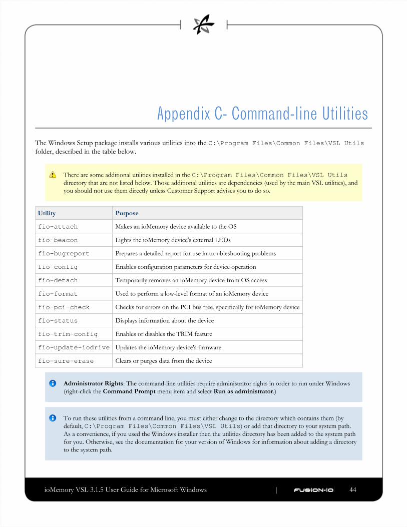
Appendix C- Command-line UtilitiesThe Windows Setup package installs various utilities into the C:\Program Files\Common Files\VSL Utilsfolder, described in the table below.
There are some additional utilities installed in the C:\Program Files\Common Files\VSL Utilsdirectory that are not listed below. Those additional utilities are dependencies (used by the main VSL utilities), and
you should not use them directly unless Customer Support advises you to do so.
Utility Purpose
fio-attach Makes an ioMemory device available to the OS
fio-beacon Lights the ioMemory device's external LEDs
fio-bugreport Prepares a detailed report for use in troubleshooting problems
fio-config Enables configuration parameters for device operation
fio-detach Temporarily removes an ioMemory device from OS access
fio-format Used to perform a low-level format of an ioMemory device
fio-pci-check Checks for errors on the PCI bus tree, specifically for ioMemory device
fio-status Displays information about the device
fio-trim-config Enables or disables the TRIM feature
fio-update-iodrive Updates the ioMemory device's firmware
fio-sure-erase Clears or purges data from the device
Administrator Rights: The command-line utilities require administrator rights in order to run under Windows
(right-click the menu item and select .)Command Prompt Run as administrator
To run these utilities from a command line, you must either change to the directory which contains them (by
default, ) or add that directory to your system path.C:\Program Files\Common Files\VSL UtilsAs a convenience, if you used the Windows installer then the utilities directory has been added to the system path
for you. Otherwise, see the documentation for your version of Windows for information about adding a directory
to the system path.

ioMemory VSL 3.1.5 User Guide for Microsoft Windows | __________________ ___ ___ 45
There are (Help) and (Version) options for all of the utilities. Also, and cause the utility to exit after-h -v -h -vdisplaying the information.
fio-attachDescription
Attaches the ioMemory device and makes it available to Windows. You can then partition the ioMemory device, or set
it up as part of a RAID array, using the Windows Disk Management utility. This command displays a progress bar and
percentage as it completes the attach process.
In most cases, the ioMemory VSL automatically attaches the device on load and does a scan. You only need to
run fio-attach if you ran fio-detach or if you set the ioMemory VSL's auto_attach parameter to 0.
If the ioMemory device is in minimal mode, then auto-attach is disabled until the cause of the device being in
minimal mode is fixed.
Syntax
fio-attach <device> [options]
where is the name given by the ioMemory VSL to your device. This name is , where <device> /dev/fctx x
indicates the PCIe bus number where you installed the ioMemory device. (For example, the name refers/dev/fct4to the ioMemory device installed in PCIe Bus 4 in your Windows system. Use ioManager or to view thisfio-statusbus number.)
You can specify multiple ioMemory devices. For example, indicates the ioMemory devices/dev/fct1 /dev/fct2installed in PCIe Buses 1 and 2 in your Windows system.
Option Description
-c Attach only if clean.
-q Quiet: disables the display of the progress bar and percentage.
fio-beaconDescription
Lights the ioMemory device's three LEDs to locate the device. You should first detach the ioMemory device and then
run .fio-beacon
ioMemory VSL 3.1.5 User Guide for Microsoft Windows | __________________ ___ ___ 46
Syntax
fio-beacon <device> [options]
where is the name given by the ioMemory VSL to your device. This name is , where <device> /dev/fctx x
indicates the device number.
Options Description
-0 Off: (Zero) Turns off the three LEDs
-1 On: Lights the three LEDs
-p Prints the PCI bus ID of the device at <device> to standard output. Usage and error information may be written to
standard output rather than to standard error.
fio-bugreportDescription
Prepares a detailed report of the device for use in troubleshooting problems.
Syntax
fio-bugreport
Notes
This utility captures the current state of the device. When a performance or stability problem occurs with the device,
run the utility and send the output to for assistance in troubleshooting.fio-bugreport [email protected]
fio-bugreport runs several information-gathering utilities and combines the resulting data into a text file. The
results are saved in the directory (default installation path is utils C:\Program Files\Common Files\VSL) in a file that indicates the date and time the utility was run.Utils .cab
You are then prompted to send an e-mail describing the problem to with the bug report [email protected]
attached.

ioMemory VSL 3.1.5 User Guide for Microsoft Windows | __________________ ___ ___ 47
Sample Output
C:\Users\username>"\Program Files\Fusion-io\Utils\fio-bugreport.exe"Generating bug report. Please wait, this may take a while...---------------------------------------------Gathering all Windows Event Logs...DONEGathering Fusion-io Windows Event Logs...DONEGathering System Information...DONERunning fio utilities...DONECompressing to CAB file...DONEBug report has successfully been created:fio-bugreport-20100222_192621.cab.Please e-mail this file to [email protected]
For example, the filename for a bug report file named indicates thefiobugreport-20090921.192621.cabfollowing:
Date (20090921)
Time (192621, or 19:26:21)
fio-configDescription
Sets and gets ioMemory VSL configuration parameters for device operation. For a list of parameters, see Parameters
below.Reference
In order for the parameter value(s) to be enforced, you must either reboot the system or first disable and then
re-enable all ioMemory devices in the . This will reload the ioMemory VSL with the values(s)Device Manager
enabled. Be sure to use the option if you plan to reboot.-p
Syntax
fio-config [options] [<parameter>] [<value>]
where is the ioMemory VSL parameter you wish to set, and is the value you wish to set for<parameter> <value>the parameter.
Options Description
-e Enumerate configuration parameter names and values.
-g<name>
Get the configuration parameter.

ioMemory VSL 3.1.5 User Guide for Microsoft Windows | __________________ ___ ___ 48
-p<name>
Set and make the configuration parameter persistent. Use this option if you want the parameter setting to
.remain after a reboot
-s<name>
Set the configuration parameter in memory only.
-V Print verbose information.
-v Print version information.
Parameters Reference
The following table describes the ioMemory VSL parameters you can set with the utility.fio-config
fio-config options must be entered in uppercase to function properly.
MSI (Message Signaled Interrupts) is enabled by default for this platform, and it cannot be disabled using
.fio-config
Other than and , all options areFIO_PREALLOCATE_MEMORY FIO_EXTERNAL_POWER_OVERRIDE fio-configglobal—they apply to all Fusion-io devices in the computer.
By setting the and parameters, you FIO_PREALLOCATE_MEMORY FIO_EXTERNAL_POWER_OVERRIDE. If you wish to add additional serial numbers to the list, you must list the new serialoverwrite previous values
numbers as well as the previously entered numbers. To clear the list, set the parameter without any values.
Option Default
(min/max)
Description
AUTO_ATTACH 1 (0, 1) Always attach the device on driver load ( ).1
IODRIVE_TINTR_HW_WAIT 0 (0, 255) Interval (microseconds) to wait between hardware interrupts
FIO_EXTERNAL_POWER_OVERRIDE No devices
selected
Allows selected devices to draw full power from the PCIe
slot. Where the for this parameter is a<value>comma-separated list of adapter serial numbers.
Use with care, see Enabling PCIe Power
for more information.Override
FORCE_MINIMAL_MODE 0 (0, 1) Force minimal mode on the device ( ), this parameter is set1to false ( ) by default.0
PARALLEL_ATTACH 0 (0, 1) Enable parallel attach of multiple devices ( ), this parameter1is set to false ( ) by default.0

ioMemory VSL 3.1.5 User Guide for Microsoft Windows | __________________ ___ ___ 49
FIO_PREALLOCATE_MEMORY 0 For the selected device, pre-allocate all memory necessary to
have the drive usable as swap space. For example:
fio-config /dev/fct0 -pFIO_PREALLOCATE_MEMORY ="1234,54321"
where and are serial numbers"1234" "54321"obtained from .fio-status
WIN_DISABLE_ALL_AFFINITY 0 (affinity is
enabled)
When is set to 0, theWIN_DISABLE_ALL_AFFINITYdriver will enable interrupt and worker thread affinity in the
driver. When is set to WIN_DISABLE_ALL_AFFINITY, the driver will disable all affinity settings. This is an1
override of any other affinity settings. The driver must be
reloaded for this parameter to take effect.
WIN_DISABLE_DEFAULT_NUMA_AFFINITY 0 ("default"
NUMA
affinity is
enabled)
When isWIN_DISABLE_DEFAULT_NUMA_AFFINITYset to , during initialization, the driver will query Windows0for the affinity settings assigned to the adapter by the OS.
This is what is known as the "default NUMA affinity". Once
the affinity is queried correctly, the driver sets the affinity of
the adapter's interrupt and associated worker threads to the
default OS setting. This generally has the effect of setting
the affinity of the interrupt and worker threads to all
processors on a single NUMA node in the system. When
is set to WIN_DISABLE_DEFAULT_NUMA_AFFINITY, the driver will ignore the affinity settings assigned to the1
adapter by the OS. The driver must be reloaded for this
parameter to take effect.
FIO_AFFINITY N/A FIO_AFFINITY is a list of <affinity triplets to specify the affinity settingsspecification>
of all adapters in the system. Each item in the triplet is
separated by a comma, and each triplet set is separated by a
semicolon.
For syntax information and examples
showing the use of this parameter, see
.Appendix I- NUMA Configuration

ioMemory VSL 3.1.5 User Guide for Microsoft Windows | __________________ ___ ___ 50
fio-detachDescription
Detaches the ioMemory device and removes the corresponding block device from the OS. The fctx fio-detachutility waits until the device completes all read/write activity before executing the detach operation. By default, the
command also displays a progress bar and percentage as it completes the detach.
Before using this utility, ensure that the device you want to detach is not currently mounted and in use.
Syntax
fio-detach <device> [options]
where is the name given by the ioMemory VSL to your device. This name is , where <device> /dev/fctx x
indicates the device number. (The number reflects the PCIe bus for the ioDrive.) For example, the name /dev/fct4refers to the ioMemory device installed in PCIe Bus 4 in your system. (Use to view this number.)fio-status
You can specify multiple ioMemory devices. For example, indicates the ioDrives installed/dev/fct1 /dev/fct2in PCIe Buses 1 and 2 in your Windows system.
Options Description
-f Force: Causes an immediate detach (does not save metadata).
Although the (force) option causes the ioMemory device to detach, even in a RAID setup, it is-fstrongly recommended to take the drives/volume offline using the Windows Disk Management
plug-in, then perform the detach. Forcing the detach may result in loss of data.
-i Immediate: Causes a forced immediate detach (does not save metadata). This will fail if the device is in use by the
OS.
-q Quiet: Disables the display of the progress bar and percentage.
Notes
Attempting to detach an ioMemory device may fail with an error indicating that the device is busy. This typically may
occur if the device is part of a software RAID (0,1,5) volume. Windows refuses the request to detach the drive
associated with the ioMemory device because it is part of a RAID volume and may cause the volume to fail. This does
not occur with simple volumes (such as a single ioMemory device). To detach in this case, take the volume offline
using the Disk Management MMC plug-in application.

ioMemory VSL 3.1.5 User Guide for Microsoft Windows | __________________ ___ ___ 51
fio-formatDescription
The ioMemory device ships pre-formatted, so is generally not required except to change thefio-formatlogical size or block size of the device, or to erase user data on the device.
Performs a low-level format of the device. By default, displays a progress-percentage indicator as it runs.fio-format
Use this utility with care, as it deletes all user information on the device.
Using a larger block (sector) size, such as 4096 bytes, can significantly reduce worst-case ioMemory VSL host
memory consumption; however, some applications are not compatible with non-512-byte sector sizes.
If you do not include the or options, the device size defaults to the advertised capacity. If used, the and-s -o -s options must include the size or percentage indicators.-o
Syntax
fio-format [options] <device>
where is the name given by the ioMemory VSL to your device. This name is , where <device> /dev/fctx x
indicates the PCIe bus number where you installed the ioMemory device. (For example, the name refers/dev/fct4to the ioMemory device installed in PCIe Bus 4 in your Windows system. Use ioManager or to view thisfio-statusbus number.)
Options Description
-b <sizeB|K>
Set the block (sector) size, in bytes or KiBytes (base 2). The default is 512 bytes. For example: -b 512Bor ( in is optional).-b 4K B 512B
-f Force the format size, bypassing normal checks and warnings. This option may be needed in rare situations
when does not proceed properly. (The "Are you sure?" prompt still appears unless you usefio-formatthe option.)-y
-q Quiet mode: Disable the display of the progress-percentage indicator.

ioMemory VSL 3.1.5 User Guide for Microsoft Windows | __________________ ___ ___ 52
-s <sizeM|G|T|%>
Set the device capacity as a specific size (in TB, GB, or MB) or as a percentage of the advertised capacity:
T Number of terabytes (TB) to format
G Number of gigabytes (GB) to format
M Number of megabytes (MB) to format
% Percentage, such as 70% (the percent sign must be included)
-o <sizeB|K|M|G|T|%>
Over-format the device size (to greater than the advertised capacity), where the maximum size equals the
maximum physical capacity. If a percentage is used, it corresponds to the maximum physical capacity of the
device. (Size is required for the option; see the option above for size indicator descriptions.)-o -s
Before you use this option, please discuss your use case with Customer Support.
-R Disable fast rescan on unclean shutdowns at the cost of some capacity.
-y Auto-answer "yes" to all queries from the application (bypass prompts).
fio-pci-checkDescription
Checks for errors on the PCI bus tree, specifically for ioMemory devices. This utility displays the current status of each
ioMemory device. It also prints the standard PCI Express error information and resets the state.
It is perfectly normal to see a few errors (perhaps as many as five) when fio-pci-check is initially run. Subsequent
runs should reveal only one or two errors during several hours of operation.
The ioMemory VSL be loaded to run this utility. Some PCI errors cannot be reset in Windows.must
Syntax
fio-pci-check [options]
Options Description
-d <value> 1 = Disable the link; 0 = bring the link up
-f Scan every device in the system.
-r Force the link to retrain.
-v Verbose: Print extra data about the hardware.
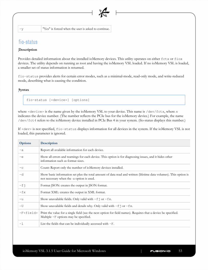
ioMemory VSL 3.1.5 User Guide for Microsoft Windows | __________________ ___ ___ 53
-y "Yes" is forced when the user is asked to continue.
fio-statusDescription
Provides detailed information about the installed ioMemory devices. This utility operates on either or fctx fioxdevices. The utility depends on running as root and having the ioMemory VSL loaded. If no ioMemory VSL is loaded,
a smaller set of status information is returned.
fio-status provides alerts for certain error modes, such as a minimal-mode, read-only mode, and write-reduced
mode, describing what is causing the condition.
Syntax
fio-status [<device>] [options]
where is the name given by the ioMemory VSL to your device. This name is , where <device> /dev/fctx x
indicates the device number. (The number reflects the PCIe bus for the ioMemory device.) For example, the name
refers to the ioMemory device installed in PCIe Bus 4 in your system. (fio-status displays this number.)/dev/fct4
If is not specified, displays information for all devices in the system. If the ioMemory VSL is not<dev> fio-statusloaded, this parameter is ignored.
Options Description
-a Report all available information for each device.
-e Show all errors and warnings for each device. This option is for diagnosing issues, and it hides other
information such as format sizes.
-c Count: Report only the number of ioMemory devices installed.
-d Show basic information set plus the total amount of data read and written (lifetime data volumes). This option is
not necessary when the -a option is used.
-fj Format JSON: creates the output in JSON format.
-fx Format XML: creates the output in XML format.
-u Show unavailable fields. Only valid with or .-fj -fx
-U Show unavailable fields and details why. Only valid with or .-fj -fx
-F<field> Print the value for a single field (see the next option for field names). Requires that a device be specified.
Multiple options may be specified.-F
-l List the fields that can be individually accessed with .-F

ioMemory VSL 3.1.5 User Guide for Microsoft Windows | __________________ ___ ___ 54
Output Change
Starting with version 3.0.0 and later, the standard formatting of ouput has changed. This willfio-statusaffect any custom management tools that used the output of this utility.
Basic Information: If no options are used, reports the following basic information:fio-status
Number and type of cards installed in the system
Software version
Adapter information:
Adapter type
Product number
External Power Supply
PCI power limit threshold (if available)
Connected ioMemory devices
Block device information:
Attach status
Product name
Product number
Serial number
PCIe slot number
Firmware version
Size of the device, out of total capacity
Internal temperature (average and maximum, since ioMemory VSL load) in degrees Centigrade
Health status: healthy, nearing wearout, write-reduced or read-only
Reserve capacity (percentage)
Warning capacity threshold (percentage)
Data Volume Information: If the -d option is used, the following data volume information is reported toin addition
the basic information:
Physical bytes written
Physical bytes read
ioMemory VSL 3.1.5 User Guide for Microsoft Windows | __________________ ___ ___ 55
All Information: If the option is used, all information is printed, which includes the following information -a in
to basic and data volume information:addition
Adapter information:
Manufacturer number
Date of manufacture
Power loss protection status
PCIe bus voltage (avg, min, max)
PCIe bus current (avg, max)
PCIe power limit threshold (watts)
PCIe slot available power (watts)
PCIe negotiated link information (lanes and throughput)
Block device information:
Part number
Manufacturer's code
Manufacturing date
Vendor and sub-vendor information
Size of the device, out of total capacity
Format status and sector information (if device is attached)
FPGA ID and Low-level format GUID
PCIe slot available power
PCIe negotiated link information
Card temperature, in degrees Centigrade
Internal voltage: avg. and max.
Auxiliary voltage: avg. and max.
Percentage of good blocks, data and metadata
Lifetime data volume statistics
Error Mode Information: If the ioMemory VSL is in minimal mode, read-only mode, or write-reduced mode when
is run, the following differences occur in the output:fio-status

ioMemory VSL 3.1.5 User Guide for Microsoft Windows | __________________ ___ ___ 56
1.
2.
Attach status is "Status unknown: Driver is in MINIMAL MODE:"
The reason for the minimal mode state is displayed (such as "Firmware is out of date. Update firmware.")
"Geometry and capacity information not available." is displayed.
No media health information is displayed.
fio-sure-erase
As a best practice, do not use this utility if there are any ioMemory devices installed in the system that you do not
want to clear or purge. First remove any devices that you do not want to accidentally erase. Once the data is
removed with this utility it is gone forever. It is not recoverable.
Before you use this utility, be sure to back up any data that you wish to preserve.
After using , format the device using before using the device again.fio-sure-erase fio-format
If the device is in Read-only mode, perform a format using before running .fio-format fio-sure-eraseIf the device is in Minimal mode, then cannot erase the device. Updating the firmware mayfio-sure-erasetake the device out of Minimal Mode. If the device remains in Minimal mode, contact Customer Support at
for further [email protected]
In order to run , the block device . See the section for morefio-sure-erase must be detached fio-detachinformation.
Description
The is a command-line utility that securely removes data from ioMemory devices. It complies withfio-sure-erasethe "Clear" and "Purge" level of destruction from the following standards:
DOD 5220.22-M – Comply with instructions for Flash EPROM
NIST SP800-88– Comply with instructions for Flash EPROM
See below for more information on Clear and Purge support.
Registry Requirement
On Windows, a registry key must be created to configure the driver for ECC-bypass mode:

ioMemory VSL 3.1.5 User Guide for Microsoft Windows | __________________ ___ ___ 57
1.
2.
3.
Locate the following key:
HKEY_LOCAL_MACHINE\SYSTEM\CurrentControlSet\Services\fiodrive\Parameters
Create a DWORD key underneath it called "BypassECC" and set the value to "1".
Restart the computer before running the utility.
Syntax
fio-sure-erase [options] <device>
Where is the name given by the ioMemory VSL to your device. This name is . For example,<device> /dev/fctxthe name refers to the ioMemory device installed in PCIe Bus 4 in your Windows system. Use /dev/fct4
to view this bus number.fio-status
Products with Multiple Devices
fio-sure-erase works on individual ioMemory devices. For example, if you are planning to purge an
ioDrive Duo device, you will need to perform this operation on each of the product's two ioMemory devices.
Options Description
-p Purge instead of Clear: performs a write followed by an erase. For more information on Purge, see below.
Purging the device may take hours to accomplish, depending on the size of the device that needs to
be purged.
-y No confirmation: do not require a yes/no response to execute the utility.
-q Quiet: do not display the status bar.
If you run with no options, a Clear is performed. For more information, see below.fio-sure-erase
Each block of memory consists of uniform 1 bits or 0 bits.
Clear Support
A "Clear" is the default state of running (with no options), and refers to the act of performing afio-sure-erasefull low-level erase (every cell pushed to "1") of the entire NAND media, including retired erase blocks.
Metadata that is required for operation will not be destroyed (media event log, erase counts, physical bytes
read/written, performance and thermal history), but any user-specific metadata will be destroyed.
The following describes the steps taken in the Clear operation:
ioMemory VSL 3.1.5 User Guide for Microsoft Windows | __________________ ___ ___ 58
1.
2.
3.
4.
1.
2.
3.
4.
5.
Creates a unity map of every addressable block (this allows to address every block,fio-sure-eraseincluding previously unmapped bad blocks).
For each block, performs an erase cycle (every cell is pushed to "1").
Restores the bad block map.
Formats the device (the purpose of this is to make the device usable again, the utility erases all of the headers
during the clear).
Purge Support
A "Purge" is implemented by using the option with . Purge refers to the act of first overwriting-p fio-sure-erasethe entire NAND media (including retired erase blocks) with a single character (every cell written to logical "0"), and
then performing a full chip erase (every cell pushed to "1") across all media (including retired erase blocks).
Metadata that is required for operation will be destroyed (media event log, erase counts, physical bytesnot
read/written, performance and thermal history), but any user-specific metadata will be destroyed.
The following describes the steps taken in the Purge operation:
Creates a unity map of every addressable block (this allows to address every block,fio-sure-eraseincluding previously unmapped bad blocks).
For each block, performs a write cycle (every cell written to "0").
For each block, performs an erase cycle (every cell pushed to "1").
Restores the bad block map.
Formats the drive (the purpose of this is to make the drive usable again, the utility erases all of the headers
during the clear).
fio-trim-configDescription
Enables or disables the TRIM feature (Windows service), which reclaims available space from the file system. It is
generally recommended that TRIM be enabled for best performance. TRIM is enabled by default. Running this utility
with no options displays the current TRIM status.
This utility affects all ioMemory devices in the system. You cannot enable or disable TRIM for only selected
devices. Settings take place immediately, there is no need to reboot the system or the device.
Syntax
fio-trim-config [options]
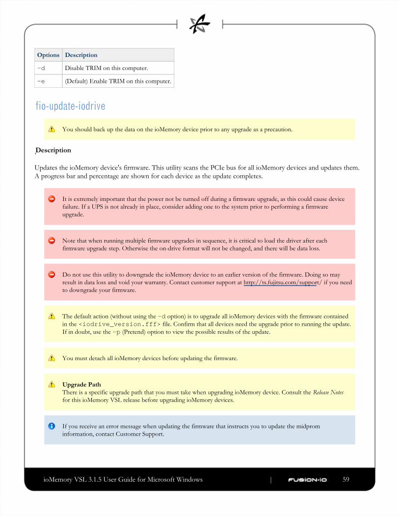
ioMemory VSL 3.1.5 User Guide for Microsoft Windows | __________________ ___ ___ 59
Options Description
-d Disable TRIM on this computer.
-e (Default) Enable TRIM on this computer.
fio-update-iodrive
You should back up the data on the ioMemory device prior to any upgrade as a precaution.
Description
Updates the ioMemory device's firmware. This utility scans the PCIe bus for all ioMemory devices and updates them.
A progress bar and percentage are shown for each device as the update completes.
It is extremely important that the power not be turned off during a firmware upgrade, as this could cause device
failure. If a UPS is not already in place, consider adding one to the system prior to performing a firmware
upgrade.
Note that when running multiple firmware upgrades in sequence, it is critical to load the driver after each
firmware upgrade step. Otherwise the on-drive format will not be changed, and there will be data loss.
Do not use this utility to downgrade the ioMemory device to an earlier version of the firmware. Doing so may
result in data loss and void your warranty. Contact customer support at http://ts.fujitsu.com/support/ if you need
to downgrade your firmware.
The default action (without using the option) is to upgrade all ioMemory devices with the firmware contained-din the file. Confirm that all devices need the upgrade prior to running the update.<iodrive_version.fff>If in doubt, use the (Pretend) option to view the possible results of the update.-p
You must detach all ioMemory devices before updating the firmware.
Upgrade Path
There is a specific upgrade path that you must take when upgrading ioMemory device. Consult the Release Notes
for this ioMemory VSL release before upgrading ioMemory devices.
If you receive an error message when updating the firmware that instructs you to update the midprom
information, contact Customer Support.

ioMemory VSL 3.1.5 User Guide for Microsoft Windows | __________________ ___ ___ 60
Syntax
fio-update-iodrive [options] <iodrive_version.fff>
where is the path and firmware archive file provided by Fusion-io. The default path is <iodrive_version.fff>. This parameter is required.C:\Program Files\Fusion-io ioMemory VSL\Firmware
Options Description
-d Updates the specified devices (by , where is the number of the device shown in ). If thisfctx x fio-statusoption is not specified, all devices are updated.
Use the option with care, as updating the wrong ioMemory device could damage your device.-d
-f Force upgrade (used primarily to downgrade to an earlier firmware version). If the ioMemory VSL is not loaded, this
option also requires the option.-d
Use the -f option with care, as it could damage your card.
-l List the firmware available in the archive.
-c Clears locks placed on a device.
-p Pretend: Shows what updates would be done. However, the actual firmware is not modified.
-q Runs the update process without displaying the progress bar or percentage.
-y Confirm all warning messages.
All three external LED indicators light up during the update process.

ioMemory VSL 3.1.5 User Guide for Microsoft Windows | __________________ ___ ___ 61
Appendix D- TRIM Support
Introduction
TRIM is used to address a unique property of solid-state devices. The problem stems from the fact that when a user
deletes a file, the device that contains the file does not recognize that it can reclaim that space. Instead, the device
assumes the data is valid until the system informs the device it can overwrite that data. This is fine for a normal hard
device, because you can continually write to the same sector of the device without significant degradation. A solid-state
device, on the other hand, writes to different flash memory areas when the same logical sector is written to.
Because of the way flash memory handles writes, having a full SSD can cause significant reduction in write throughput.
Currently available storage stacks and file systems were not designed with this caveat in mind. The SSD software must
assume that all sectors contain valid data, and therefore always treat the device as full. In reality, a file system does not
normally contain a full device's worth of data.
TRIM is an enhancement to existing file systems that informs the SSD software of logical sectors that do not contain
valid user data. TRIM retrieves this information from a file system when a file has been deleted, and it informs the
device that it can reclaim the space held by that file. This allows the wear-leveling software to reclaim that space as
reserve to handle future write operations.
In order for TRIM to do this, it continually runs in the background and monitors the file system(s) being used on
Fusion-io devices. The process is meant to be "lazy" so as not to noticeably impact the performance of the computer.
Platforms
The TRIM feature is available on ioMemory devices for Windows operating systems starting with Windows Server
2003.
TRIM capabilities have been built into Windows 7 and Windows Server 2008 R2 operating systems. ioMemory
devices support Windows 7 TRIM, which means that Fusion-io TRIM is unnecessary under Windows Server 2008
R2, and it will not run when this operating system is present. No system changes are needed. The Fusion-io TRIM
service will automatically shut off if it detects the Windows Server 2008 R2 operating system.
Using the TRIM Service
TRIM runs quietly in the background as a Windows Service a few minutes after the computer is booted, so as not to
slow down the boot process. However, you can fine-tune TRIM by using the configurable settings described below.

ioMemory VSL 3.1.5 User Guide for Microsoft Windows | __________________ ___ ___ 62
1.
2.
1.
2.
3.
Starting and Stopping TRIM
To start or stop the TRIM service through the Windows Services Manager,
Search for "Fusion-io Trim Service".
Click "Start service" or "Stop service".
Note that stopping the service only stops it for that session. Restarting the computer causes TRIM to run again.
Enabling TRIM
To enable the Fusion-io TRIM service,
Open a registry editor.
Navigate to
HKEY_LOCAL_MACHINE\SYSTEM\CurrentControlSet\Services\fiodrive\Parameters
Add the value as a (see the description below).Stop the TRIM service (by either of theTrimEnabled DWORDtwo previously mentioned methods) and restart it; or, restart the computer.
The utility will set the flag for you and does not require a reboot of yourfio-trim-config TrimEnabledsystem or a manual restart of the service for the changes to take effect. This utility is the preferred method of
enabling and disabling TRIM as it prevents the user from having to edit the registry themselves which has the
potential to produce undesired consequences.
TrimEnabled
This registry value controls whether TRIM will run, regardless of the user starting and stopping TRIM through either
of the two previously mentioned methods. If this value is present and set to 1, then TRIM will run as normal (unless
you have stopped the service using the previously mentioned methods). If this value is set to 0 before attempting to
start the Fusion-io TRIM service, the service will not run until the value is changed to 1 (or removed from the registry)
and the service manually restarted. If this value is not present, TRIM assumes it should run unless you stop it. Note
that this value persists across sessions, so if you restart the computer and set this value to 0, TRIM will not run when
the computer starts again.
Controlling TRIM Aggressiveness
You can control how aggressive the TRIM service is. The default settings for TRIM minimize impact on computer
performance while allowing the ioMemory device(s) to perform at their best. However, if a drive is being used with a
write-intensive application, then you may want TRIM to be more aggressive. To do this, you'll need to add a few
registry entries.
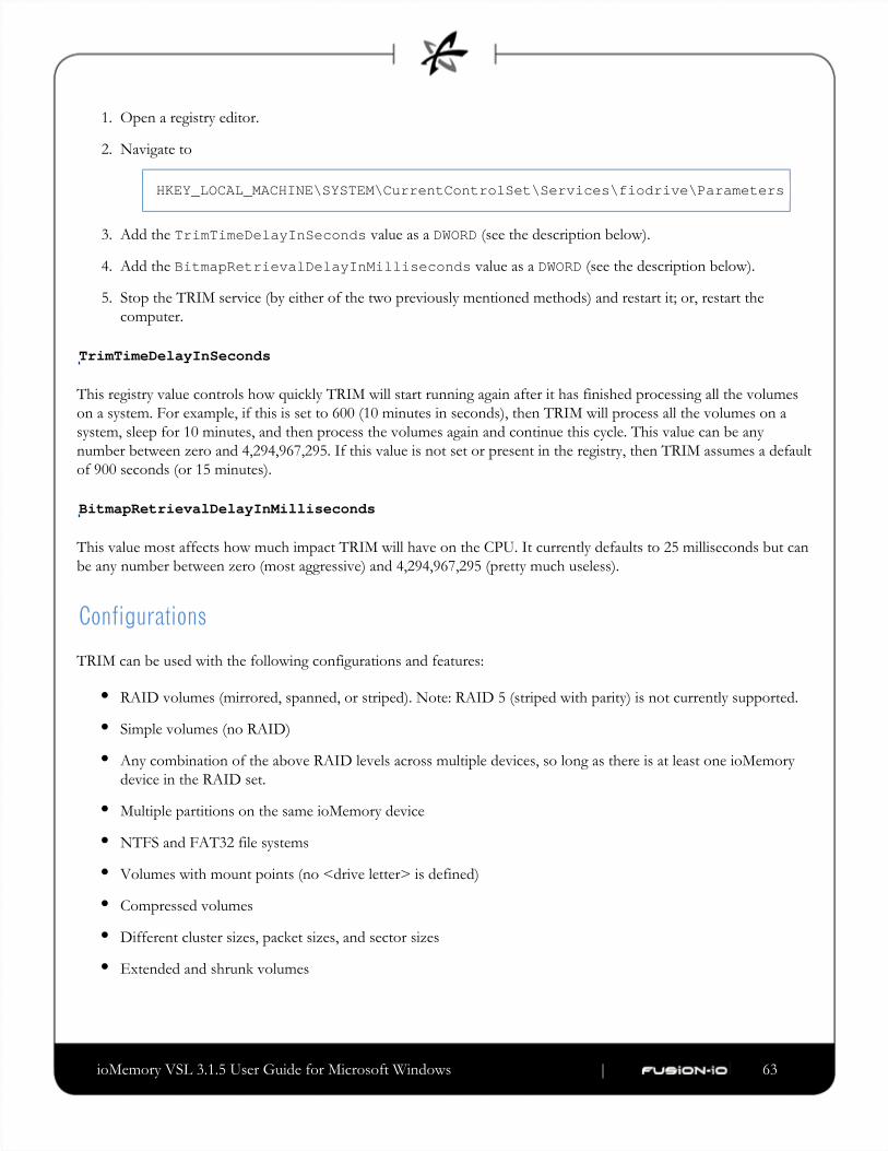
ioMemory VSL 3.1.5 User Guide for Microsoft Windows | __________________ ___ ___ 63
1.
2.
3.
4.
5.
Open a registry editor.
Navigate to
HKEY_LOCAL_MACHINE\SYSTEM\CurrentControlSet\Services\fiodrive\Parameters
Add the value as a (see the description below).TrimTimeDelayInSeconds DWORD
Add the value as a (see the description below).BitmapRetrievalDelayInMilliseconds DWORD
Stop the TRIM service (by either of the two previously mentioned methods) and restart it; or, restart the
computer.
TrimTimeDelayInSeconds
This registry value controls how quickly TRIM will start running again after it has finished processing all the volumes
on a system. For example, if this is set to 600 (10 minutes in seconds), then TRIM will process all the volumes on a
system, sleep for 10 minutes, and then process the volumes again and continue this cycle. This value can be any
number between zero and 4,294,967,295. If this value is not set or present in the registry, then TRIM assumes a default
of 900 seconds (or 15 minutes).
BitmapRetrievalDelayInMilliseconds
This value most affects how much impact TRIM will have on the CPU. It currently defaults to 25 milliseconds but can
be any number between zero (most aggressive) and 4,294,967,295 (pretty much useless).
Configurations
TRIM can be used with the following configurations and features:
RAID volumes (mirrored, spanned, or striped). Note: RAID 5 (striped with parity) is not currently supported.
Simple volumes (no RAID)
Any combination of the above RAID levels across multiple devices, so long as there is at least one ioMemory
device in the RAID set.
Multiple partitions on the same ioMemory device
NTFS and FAT32 file systems
Volumes with mount points (no <drive letter> is defined)
Compressed volumes
Different cluster sizes, packet sizes, and sector sizes
Extended and shrunk volumes

ioMemory VSL 3.1.5 User Guide for Microsoft Windows | __________________ ___ ___ 64
Appendix E- Monitoring the Health of ioMemoryDevices
This section describes how the health of ioMemory devices can be measured and monitored in order to safeguard data
and prolong device lifetime.
NAND Flash and Component Failure
An ioMemory device is a highly fault-tolerant storage subsystem that provides many levels of protection against
component failure and the loss nature of solid-state storage. As in all storage subsystems, component failures may
occur.
By properly selecting NAND flash media for the hosted application and proactively monitoring device age and health,
you can ensure reliable performance over the intended product life.
Health Metrics
The ioMemory VSL manages block retirement using pre-determined retirement thresholds. The ioSphere and the
utilities show a health indicator that starts at 100 and counts down to 0. As certain thresholds arefio-statuscrossed, various actions are taken.
At the 10% healthy threshold, a one-time warning is issued. See the 'monitoring' section below for methods for
capturing this alarm event.
At 0%, the device is considered unhealthy. It enters mode, which somewhat prolongs its lifespan so datawrite-reduced
can be safely migrated off. In this state the ioMemory device behaves normally, except for the reduced write
performance.
After the 0% threshold, the device will soon enter mode – any attempt to write to the ioMemory device causesread-only
an error. Some filesystems may require special mount options in order to mount a read-only block device in addition
to specifying that the mount should be read-only.
For example, under Linux, ext3 requires that " " is used, the " " option tells the filesystem to-o ro,noload noloadnot try and replay the journal.
Read-only mode should be considered a final opportunity to migrate data off the device, as device failure is more likely
with continued use.

ioMemory VSL 3.1.5 User Guide for Microsoft Windows | __________________ ___ ___ 65
The ioMemory device may enter failure mode. In this case, the device is offline and inaccessible. This can be caused by
an internal catastrophic failure, improper firmware upgrade procedures, or device wearout.
For service or warranty-related questions, contact the company from which you purchased the device.
For products with multiple ioMemory devices, these modes are maintained independently for each device.
Health Monitoring Techniques
fio-status: Output from the utility shows the health percentage and device state. These items arefio-statusreferenced as " " in the sample output below.Media status
Found 1 ioDrive in this systemFusion-io driver version: 2.2.3 build 240Adapter: ioDriveFusion-io ioDrive 160GB, Product Number:FS1-002-161-ES...Media status: Healthy; Reserves: 100.00%, warn at 10.00%; Data: 99.12%Lifetime data volumes: Physical bytes written: 6,423,563,326,064 Physical bytes read : 5,509,006,756,312
ioSphere: In the Device Report tab, look for the Reserve Space percentage in the right column. The higher the
percentage, the healthier the drive is likely to be.
SNMP/SMI-S: On Windows or Linux, see the corresponding appendix for details on how to configure SNMP or
SMI-S health indicators.
The following Health Status messages are produced by the utility:fio-status
Healthy
Low metadata
Read-only
Reduced-write
Unknown
ioMemory VSL 3.1.5 User Guide for Microsoft Windows | __________________ ___ ___ 66
Software RAID and Health Monitoring
Software RAID stacks are typically designed to detect and mitigate the failure modes of traditional storage media. The
ioMemory device attempts to fail as gracefully as possible, and these new failure mechanisms are compatible with
existing software RAID stacks. An ioMemory device in a RAID group will fail to receive data at a sufficient rate if a)
the device is in a write-reduced state, and b) it is participating in a write-heavy workload. In this case, the device will be
evicted from the RAID group. A device in read-only mode will be evicted when write I/Os are returned from the
device as failed. Catastrophic failures are detected and handled just as though they are on traditional storage devices.

ioMemory VSL 3.1.5 User Guide for Microsoft Windows | __________________ ___ ___ 67
Appendix F- Using Windows Page Files with theioMemory Devices
Introduction
This appendix describes how to effectively use paging (swap) files on ioMemory devices with Windows.
Using a page file with a traditional disk drive places practical limits on the usable size of the page file and virtual
memory, due to the poor performance of disk drives in relation to RAM. Placing the OS paging file on one or more
ioMemory devices allows much larger page files and usable virtual memory. This is due to the much faster response
times and bandwidth on ioMemory devices versus hard disks.
Configuring Device Paging Support
The ioMemory VSL can be configured to support paging files on one or more ioMemory devices. This requires that
each ioDrive used with a paging file pre-allocates the worst-case amount of memory it may need in any possible I/O
scenario. This is done on a per-adapter (ioDIMM) instance.
Because of the extra host RAM memory use, paging should be enabled only on ioMemory devices that will actually
hold a paging file. It is possible to place a single paging file on more than one ioMemory device. In this case Windows
will stripe paging I/O across all available paging files, possibly providing additional performance to the Virtual
Memory (VM) subsystem.
ioMemory VSL RAM Consumption
The amount of RAM pre-allocated per ioMemory device depends on the device's total size and the sector (block) size
selected when formatting the drive (with ).fio-format
Consult the Release Notes for this version of the software for RAM usage per GB of ioMemory device.
Using a larger sector size significantly reduces the amount of host memory consumption needed for paging support. It
is recommended that a 4K sector size be used because a) that is generally the natural size of a host memory page, and
b) it minimizes overall host memory consumption. In Windows, NTFS will generally use a cluster size of 4K, so
formatting to 512 is not useful except for applications that compatible only with 512-byte sector sizes (such as
Windows XP and Windows 2003).

ioMemory VSL 3.1.5 User Guide for Microsoft Windows | __________________ ___ ___ 68
The indicated amount is needed per ioMemory device that supports paging. You must carefully plan which ioMemory
device(s) will be used to hold a paging file.
Non-paged Memory Pool
Pre-allocated memory for the ioMemory device comes from the Windows kernel non-paged memory pool. This pool
dynamically grows as system components consume additional kernel memory. The maximum size of this pool is
restricted as follows:
Server 2003, 2008 R1/R2 - 75% of RAM up to a maximum of 128GB.
Vista/Windows 7 - 40% of RAM up to a maximum of 128GB.
The amount of in-use, non-paged pool memory should be noted when planning page file usage. This is because the
ioMemory device pre-allocates RAM, and that reduces the available physical non-paged memory. The ioMemory VSL
will fail to load if the total pre-allocated memory plus the in-use, non-paged memory exceeds the maximum non-paged
memory pool.
To determine the total non-paged memory pool use for two ioMemory devices, let's use the following example:
One ioMemory device that requires 850 MB of RAM, and the other requires 1700 MB or RAM.
Consult the for this version of the ioMemory VSL for RAM requirements.Release Notes
Both are formatted with a 4K sector size
Both will support paging files
The current allocated non-paged pool is obtained from Task Manager and, in this example, has a value of 576 MiB.
(Values shown in Task Manager are in MiB [1024x1024 = 1 MiB]). The total RAM on the system is 8000 MB and the
OS is Server 2008 R2.
First, covert the 576 MiB into MB: 576 MiB * (1 MB/1.048576 MiB) = ~549 MB
To calculate the total available non-paged pool, use the following formula:
(8000 MB x 0.75) - 549 - 850 - 1700
which still leaves 2901 MB available for the non-paged pool.
Enabling/Disabling Paging Support
Memory pre-allocation occurs during ioMemory VSL initialization. To enable paging support, you must enable the
configuration item. This can be done using the command-line utility.FIO_PREALLOCATE_MEMORY fio-configThis parameter is assigned a string with a list of decimal serial numbers of the ioMemory devices that will support a
paging file. The ioMemory VSL performs memory pre-allocation for those instances.

ioMemory VSL 3.1.5 User Guide for Microsoft Windows | __________________ ___ ___ 69
1.
2.
3.
Below is an example of using the utility to enable paging and pre-allocation on two ioMemory devicesfio-configwith serial numbers 1234 and 17834. Serial number information can be obtained using the utility.fio-status
fio-config -p FIO_PREALLOCATE_MEMORY "1234,17834"
To disable paging support on all devices, use a value of for :0 FIO_PREALLOCATE_MEMORY
fio-config -p FIO_PREALLOCATE_MEMORY "0"
To query the current value, run this command:
fio-config -g FIO_PREALLOCATE_MEMORY
An alternate method to manage (enable or disable) paging support is to use ioManager.
You must reload the ioMemory VSL for the new pre-allocation setting to take effect. Typically this can be done
by restarting the machine or using disable/enable within Device Manager for each ioMemory device instance.
Also, using the Windows System Properties to change paging file configuration requires a system restart before
the properties are applied. Therefore, you can change both FIO_PREALLOCATE_MEMORY and the system
page file configuration and then apply both with a single restart.
Windows Page File Management
By default, the ioMemory VSL disables support for page files. The previous section described how to enable support
for page files on one or more ioMemory devices. The following describes how to work with the built-in Windows
control panels to configure and set up paging files on ioMemory devices.
Setting Up Paging File(s)
To set up page files in Windows,
Go to and double-click System.Control Panel
Click from the Task pane.Advanced system settings
On the Advanced tab, click . The Performance Options dialog opens.Settings

ioMemory VSL 3.1.5 User Guide for Microsoft Windows | __________________ ___ ___ 70
4.
1.
2.
3.
4.
5.
6.
On the Advanced tab, click . The Virtual Memory dialog opens. Change
Using this dialog, you can configure a page file for each available drive in the system. Selecting the "Automatically
manage paging file size for all drives" checkbox causes Windows to create a single page file on the system drive, which
is the drive the OS is started from. This checkbox should be cleared when using an ioMemory device with a paging
file.
Windows supports up to 16 distinct paging files. To enable a page file on an ioMemory device,
Choose the ioMemory device from the device list.
Select the radio button.Custom size
Provide values in the and fields.Initial size Maximum size
Click to save the setting. Do not omit this step, or your changes will be lost.Set
Click .OK
When prompted to restart, click . This is necessary for the new page file settings to take effect.Yes
To remove a paging file on the drive, follow the steps earlier but select . For performance reasons,No paging file

ioMemory VSL 3.1.5 User Guide for Microsoft Windows | __________________ ___ ___ 71
1.
2.
3.
1.
2.
typically you will remove all paging files on any system hard disk.
The Virtual Memory dialog allows page files to be configured on available ioMemory devices, even if the
ioMemory device has not been configured to support a page file. Even though the dialog allows enabling of the
page file, following the required restart you'll notice that no page file was created on the device. Follow the
directions earlier in this document to properly enable page file support on one or more ioMemory devices.
System Drive Paging File Configuration
By default Windows creates and manages a page file on the system boot drive (typically a hard disk), which is typically
where Windows is installed. Keeping a regular page file on the system hard disk is generally not optimal, because the
hard disk's I/O performance is many orders of magnitude slower than an ioMemory device. To remedy this, you can
eliminate or minimize the size of the system boot drive page file, as explained later. Enabling page files on ioMemory
devices (but not the system drive) improves Virtual Memory (VM) subsystem performance, as the VM manager stripes
I/O across all available page files. Additionally, the ioMemory devices act as a very large memory store, which can
greatly improve memory usage for large applications.
The Windows kernel uses the system disk page file to store crash dumps. Crash dumps may be small (mini-dumps) or
large (full-kernel memory dumps). Typically, running without dump file support or with a small dump file is adequate.
There are several possible system drive page file configurations:
Eliminate all page files on any hard disks, including the system boot drive. Although this maximizes paging I/O
on ioMemory devices, no post-mortem crash dump file will be available if a system crash occurs. However, it
may be possible to re-enable a page file on the system drive and then reproduce the crash scenario.
Create a minimal-size page file on the system boot drive. The recommended minimum size is 16MB, although
Windows may warn that a minimum 400MB page file is needed.
Create a page file large enough for a full-kernel memory dump. This typically requires a page file at least the size
of installed RAM, with some recommending the size equal to RAM x 1.5.
Fusion-io is actively working on adding support for an ioMemory device being a crash dump target.
To view or change the crash dump configuration,
Go to the dialog.System Properties
Click the Advanced tab.

ioMemory VSL 3.1.5 User Guide for Microsoft Windows | __________________ ___ ___ 72
3. In the Startup and Recovery section, click . The Startup and Recovery dialog opens. Settings
In the System Failure section you can change settings to handle the system log, restart, and debugging
information.
Guaranteeing Minimum Committable Memory
If you enable "System managed size" or set a "Custom size" in the Virtual Memory dialog, you should do so with care.
If the initial size is less than the desired amount of committable virtual memory, this can cause an application to have
memory allocation failures if the amount of committed memory exceeds the currently allocated page file size or the
initial size value. When committed memory exceeds the current page file size, a request to allocate additional memory
will fail. The Windows Virtual Memory manager will slowly increase the size of the paging file up to the available size
of its drive or to the "Maximum size" custom setting, whichever is smaller.
If you want to use a large amount of committed virtual memory (more than 1.5 times the amount of RAM) and avoid
application memory allocation errors, the initial and maximum committed memory should be explicitly set for the
expected application committed memory usage. These values should generally be the same.
How Large Should You Make the Paging File?

ioMemory VSL 3.1.5 User Guide for Microsoft Windows | __________________ ___ ___ 73
The following articles explain in great detail how to size the page file appropriately.
Main Article Link: Pushing the Limits of Windows
Specific section that documents virtual memory: Pushing the Limits of Windows: Virtual Memory
Verifying Page File Operation
To verify that a page file is actively placed on an ioMemory device, you can browse for hidden files at the drive's root.
For example, run the following command at a prompt:
dir c: /ah
In the output listing there should be a file called . If no page file is present, then recheck the page filepagefile.sysconfiguration in the Virtual Memory dialog and verify that page file support has been enabled on the queried
ioMemory device.
Performance
Using the ioMemory device as the paging store can improve overall Virtual Memory system performance. Actual
benefits will vary widely with an application's virtual memory usage and with hardware platform/performance.

ioMemory VSL 3.1.5 User Guide for Microsoft Windows | __________________ ___ ___ 74
Appendix G- SNMP Test Mode and MIB Support
Introduction
This document explains how you can set up a test mode with your VSL Windows SNMP agent. This enables you to
set test values in a Windows registry and force SNMP traps without having to create the actual conditions on the
device.
For example, you can use the SNMP test mode to change the non-writeable indicator and generate a trap, or simulate a
change to the physical or logical size of the device, etc.
To use SNMP Test Mode, you must have installed the SNMP option with your ioMemory VSL.
Using Test-Mode Registry Values
The picture below shows the registry entries included for SNMP test values.

ioMemory VSL 3.1.5 User Guide for Microsoft Windows | __________________ ___ ___ 75
Each of these entries is described below. Entries marked by an asterisk (*) generate SNMP traps when set to the
indicated values, and the and variables may befusionIoDimmMIBCondition fusionIoDimmInfoStatus MIBaffected because of the changes.
All entries, except those marked by **, reflect your registry changes immediately. Entries marked by ** require a
restart of the Windows SNMP agent for the changes to take effect.
SNMP Test Registry Entry Description
ioDimmExtnAvailLogCapacityL Lower word of the available logical capacity in bytes
ioDimmExtnAvailLogCapacityU Upper word of the available logical capacity in bytes
ioDimmExtnBytesReadL Lower word of the total number of bytes read since the device was formatted

ioMemory VSL 3.1.5 User Guide for Microsoft Windows | __________________ ___ ___ 76
ioDimmExtnBytesReadU Upper word of the total number of bytes read since the device was formatted
ioDimmExtnLogBytesWrittenL Lower word of the number of user data bytes written
ioDimmExtnLogBytesWrittenU Upper word of the number of user data bytes written
ioDimmExtnPhysBytesWrittenL Lower word of the total physical bytes written
ioDimmExtnPhysBytesWrittenU Upper word of the total physical bytes written
ioDimmExtnTotalLogCapacityL Lower word of the total logical capacity in bytes as formatted
ioDimmExtnTotalLogCapacityU Upper word of the total logical capacity in bytes as formatted
ioDimmExtnTotalPhysCapacityL Lower word of the total logical capacity in bytes as formatted
ioDimmExtnTotalPhysCapacityU Upper word of the total logical capacity in bytes as formatted
ioDimmExtnUsablePhysCapacityL Lower word of the useable physical capacity in bytes. This is space that is
holding valid data, or is erased and ready for writing, or is waiting to be
reclaimed via garbage collection.
ioDimmExtnUsablePhysCapacityU Upper word of the useable physical capacity in bytes. This is space that is
holding valid data, or is erased and ready for writing, or is waiting to be
reclaimed via garbage collection.
*ioDimmInfoInternalTemp Current internal temperature of the device in degrees Celsius. If this value is
set above 78 degrees Celsius for ioDimm cards, a trap is generated. If set
above 90 degrees for HP Mezzanine cards, a trap is generated.
*ioDimmInfoFlashbackIndicator 1 = flashback redundancy is degraded; 2 = false
*ioDimmInfoNonWritableIndicator 1 = device is no longer writable because it has surpassed the read-only
threshold; 2 = false
ioDimmInfoPercentLifeRemaining Upper word of the total logical capacity in bytes as formatted
*ioDimmInfoState(trap generated if state = 4)
Current state of the attached client device:
unknown(0)
detached(1)
attached(2),
minimal(3),
error(4),
detaching(5),
attaching(6),
scanning(7),
formatting(8),
updating(9),
attach(10),
detach(11),
format(12),
update(13)
*ioDimmInfoWearoutIndicator Boolean: True = device has surpassed the wearout threshold
ioDimmTestMode Set test mode on or off

ioMemory VSL 3.1.5 User Guide for Microsoft Windows | __________________ ___ ___ 77
ioDimmTestModeIndex Number indicating the selected Fusion-io
mib Name of the MIB in use
pathname Path to the driver, set at installation
**traps Set trap generation on or off
**updateDelay Number of milliseconds to wait until getting the next value from the
ioMemory VSL to generate a trap
SNMP MIB Support
The following SNMP MIB fields are supported in Windows:
fusionIoDimmMibRevMajor fusionIoDimmInfoAdapterType
fusionIoDimmMibRevMinor fusionIoDimmInfoAdapterPort
fusionIoDimmMIBCondition fusionIoDimmInfoAdapterSerialNumber
fusionIoDimmInfoIndex fusionIoDimmInfoAdapterExtPowerPresent
fusionIoDimmInfoStatus fusionIoDimmInfoPowerlossProtectDisabled
fusionIoDimmInfoName fusionIoDimmInfoInternalTempHigh
fusionIoDimmInfoSerialNumber fusionIoDimmInfoAmbientTemp
fusionIoDimmInfoPartNumber fusionIoDimmInfoPCIBandwidthCompatibility
fusionIoDimmInfoSubVendorPartNumber fusionIoDimmInfoPCIPowerCompatibility
fusionIoDimmInfoSparePartNumber fusionIoDimmInfoActualGoverningLevel
fusionIoDimmInfoAssemblyNumber fusionIoDimmInfoLifespanGoverningLevel
fusionIoDimmInfoFirmwareVersion fusionIoDimmInfoPowerGoverningLevel
fusionIoDimmInfoDriverVersion fusionIoDimmInfoThermalGoverningLevel
fusionIoDimmInfoUID fusionIoDimmInfoLifespanGoverningEnabled
fusionIoDimmInfoState fusionIoDimmInfoLifespanGoverningTgtDate
fusionIoDimmInfoClientDeviceName fusionIoDimmExtnIndex
fusionIoDimmInfoBeacon fusionIoDimmExtnTotalPhysCapacityU
fusionIoDimmInfoPCIAddress fusionIoDimmExtnTotalPhysCapacityL
fusionIoDimmInfoPCIDeviceID fusionIoDimmExtnTotalLogCapacityU
fusionIoDimmInfoPCISubdeviceID fusionIoDimmExtnTotalLogCapacityL
fusionIoDimmInfoPCIVendorID fusionIoDimmExtnBytesReadU

ioMemory VSL 3.1.5 User Guide for Microsoft Windows | __________________ ___ ___ 78
fusionIoDimmInfoPCISubvendorID fusionIoDimmExtnBytesReadL
fusionIoDimmInfoPCISlot fusionIoDimmExtnBytesWrittenU
fusionIoDimmInfoWearoutIndicator fusionIoDimmExtnBytesWrittenL
fusionIoDimmInfoFlashbackIndicator fusionIoDimmExtnFormattedBlockSize
fusionIoDimmInfoWritableIndicator fusionIoDimmExtnCurrentRAMUsageU
fusionIoDimmInfoInternalTemp fusionIoDimmExtnCurrentRAMUsageL
fusionIoDimmInfoHealthPercentage fusionIoDimmExtnPeakRAMUsageU
fusionIoDimmInfoMinimalModeReason fusionIoDimmExtnPeakRAMUsageL
fusionIoDimmInfoReducedWriteReason fusionIoDimmWearoutTrap
fusionIoDimmInfoMilliVolts fusionIoDimmNonWritableTrap
fusionIoDimmInfoMilliVoltsPeak fusionIoDimmFlashbackTrap
fusionIoDimmInfoMilliVoltsMin fusionIoDimmTempHighTrap
fusionIoDimmInfoMilliWatts fusionIoDimmTempOkTrap
fusionIoDimmInfoMilliWattsPeak fusionIoDimmErrorTrap
fusionIoDimmInfoMilliAmps fusionIoDimmPowerlossProtectTrap
fusionIoDimmInfoMilliAmpsPeak

ioMemory VSL 3.1.5 User Guide for Microsoft Windows | __________________ ___ ___ 79
Appendix H- SMI-S Interface
With ioMemory VSL 3.0.0 and later, the SMI-S provider has a new CIM namespace: root/fio
Introduction to the SMI-S Interface
The SMI-S interface is based on Web-Based Enterprise Management (WBEM) and provides a Common Information
Model (CIM) model that represents the ioMemory device and associated software, in accordance with existing
Distributed Management Task Force (DMTF) and Storage Networking Industry Association (SNIA) Storage
Management Initiative Specification (SMI-S) standards. This model permits backward-compatible extension,
accommodating new hardware and software features developed by Fusion-io.
It is assumed that the reader is versed in WBEM, SMI-S, and DMTF standards. This document and associated model
may change at any time as feedback is received.
References
CIM Schema v2.22
http://www.dmtf.org/standards/cim/cim_schema_v2220
DMTF DSP1011, Physical Asset Profile
http://www.dmtf.org/standards/published_documents/DSP1011_1.0.2.pdf
DMTF DSP1023, Software Inventory Profile
http://www.dmtf.org/standards/published_documents/DSP1023_1.0.1.pdf
DMTF DSP1033, Profile Registration Profile
http://www.dmtf.org/standards/published_documents/DSP1033_1.0.0.pdf
DMTF DSP1075 PCI Device Profile
http://www.dmtf.org/standards/published_documents/DSP1075_1.0.0.pdf
DMTF DSP1002, Diagnostics Profile
http://www.dmtf.org/standards/published_documents/DSP1002_2.0.0.pdf
SMI-S v1.4 Architecture
http://www.snia.org/tech_activities/standards/curr_standards/smi/SMI-Sv1.4_Architecture.book.pdf
SMI-S v1.4 Common Profiles
http://www.snia.org/tech_activities/standards/curr_standards/smi/SMI-Sv1.4_CommonProfiles.book.pdf

ioMemory VSL 3.1.5 User Guide for Microsoft Windows | __________________ ___ ___ 80
1.
2.
SMI-S v1.4 Host Profiles
http://www.snia.org/tech_activities/standards/curr_standards/smi/SMI-Sv1.4_Host.book.pdf
SMI-S v1.4 Common Diagnostic Model
http://www.dmtf.org/standards/mgmt/cdm/
Installing the SMI-S WMI Provider on Windows
To install the Fusion-io SMI-S WMI provider on Windows,
Go to > .Control Panel Add & Remove Programs
Right-click and select . Make sure the WMI Windows InstallerManagement and Monitoring Tools Details
Provider is selected.
The SMI-S WMI provider for ioMemory devices will be installed and the WMI service will be restarted automatically.
Expected Warning Message
When you install the WMI provider, a warning will appear in the Windows event log with the following description:
A provider, fio-smis-wmi, has been registered in the Windows ManagementInstrumentation namespace root\fio to use the LocalSystem account. Thisaccount is privileged and the provider may cause a security violation if itdoes not correctly impersonate user requests.
This warning is expected. The WMI provider only interfaces with the ioMemory VSL and does not modify system
data.
Verifying SMI-S Installation on Windows
To verify the Fusion-io SMI-S WMI provider on Windows,

ioMemory VSL 3.1.5 User Guide for Microsoft Windows | __________________ ___ ___ 81
1.
2.
Run the wbemtest.exe program. The WMI Tester window appears.
Click Connect to display the Connect dialog. The CIM provider namespace is root\fio

ioMemory VSL 3.1.5 User Guide for Microsoft Windows | __________________ ___ ___ 82
3.
4.
Type the namespace value shown in the screenshot above and click Connect.
The WMI Tester window appears, with the namespace value filled in.
Click Enum Instances (second button on the first row) to bring up the Class Info dialog.
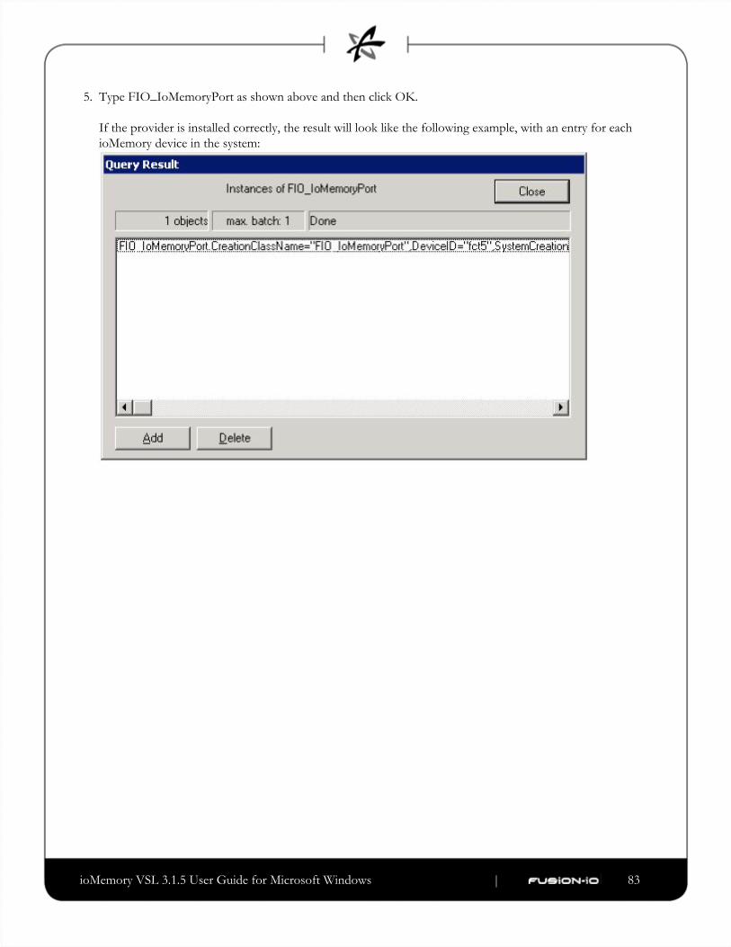
ioMemory VSL 3.1.5 User Guide for Microsoft Windows | __________________ ___ ___ 83
5. Type FIO_IoMemoryPort as shown above and then click OK.
If the provider is installed correctly, the result will look like the following example, with an entry for each
ioMemory device in the system:

ioMemory VSL 3.1.5 User Guide for Microsoft Windows | __________________ ___ ___ 84
6.
1.
2.
3.
Double-click an entry to bring up detailed information, such as in this example:
Manual Registration
If the automatic installation fails to register the provider, follow these steps to manually register it:
Stop the WMI ( ) service via the services tool or the following command line:winmgmt
net stop winmgmt
Browse to the directory using the command-line interface and run theFusion-io\SMIS\cim-schemafollowing:
mofcomp fio-reg-wmi.mof
Browse to directoryFusion-io\SMIS\WMI

ioMemory VSL 3.1.5 User Guide for Microsoft Windows | __________________ ___ ___ 85
4.
5.
Un-register and re-register the using the following commands:fio-smis-wmi.dll
regsvr32 /u fio-smis-wmi.dll
regsvr32 fio-smis-wmi.dll
Start the service via the services toolor the following command line:winmgmt
net start winmgmt
Description
SMI-S is a collection of specifications that traditionally focus on Storage Area Network (SAN) systems based on the
SCSI command set, such as Fibre Channel, iSCSI, and SAS. However, the general pattern used to model these storage
systems can be applied to solid-state, direct-attached storage systems such as those provided by Fusion-io.
ioMemory devices are modeled using the SMI-S patterns established in the Storage HBA, Direct Attached (DA) Ports,
and Host Discovered Resources Profiles. The physical aspects of the ioMemory device and all firmware and ioMemory
VSL software are modeled using published DMTF specifications, including the Physical Asset, Software Inventory,
PCI Device Profiles, and Common Diagnostic Model Profile.
The following chart describes the Fusion-io SMI-S CIM model, with ioMemory devices and their associated firmware
and software. For simplicity, the prefix FIO_ has been removed from the class names.

ioMemory VSL 3.1.5 User Guide for Microsoft Windows | __________________ ___ ___ 86
A: IOMemoryPort Class
The central instance of the model is of the class (A in the figure), a logical representation of theIOMemoryPortioMemory device. It supports the extrinsic methods necessary to provision the drive. An instance of (B)PCIDeviceand exist for each installed ioMemory device, and they are associated with instances of IOMemoryPort
(1). An instance of (C), which contains important performance and capacityConcreteIdentity SSDStatisticsdata for the device, is associated by an association (2) to each . ElementStatisticalData IOMemoryPort
is scoped by an instance of the class. The (3) aggregationIOMemoryPort ComputerSystem SystemDeviceaggregates within the containing .IOMemoryPort ComputerSystem
E: IOMemoryPortController Class
An instance of (E) represents the ioMemory VSL used to control the installedIOMemoryPortControllerioMemory devices. specializes , and it aggregates IOMemoryPortController CIM_PortController
with the (4) aggregation. The software version and vendor information areIoMemoryPort ControlledByrepresented by the (F) instance that is associated to (E) via SoftwareIdentity IOMemoryPortController
(5). The that represents the installed ioMemory VSL softwareElementSoftwareIdentity SoftwareIdentityis associated to the scoping using the association (6).ComputerSystem InstalledSoftwareIdentity
An instance of the class (G) represents both ends of the logical data path between the ProtocolEndpoint and the solid-state storage. This aspect of the model is derived from the pattern in the DA PortsIOMemoryPort
Profile, where the port is both an initiator and target. is associated to the by ProtocolEndpoint IOMemoryPort (7) and to the by (8).DeviceSAPImplementation ComputerSystem HostedAccessPoint

ioMemory VSL 3.1.5 User Guide for Microsoft Windows | __________________ ___ ___ 87
H: LogicalSSD Class (Block Device)
The block device exposed to applications (file systems, database, and logical volume manager) is modeled using an
instance of (H), a subclass of . It is associated with a (J) using the LogicalSSD CIM_DiskDrive StorageExtent association (9), but the will always be present. It is also associated to the MediaPresent StorageExtent
(G) representing the using (10) and to theProtocolEndpoint IOMemoryPort SAPAvailableForElementscoping using (3).ComputerSystem SystemDevice
ioMemory devices, being PCIe devices, are also represented by an instance of the class (B). PCIDevice is an alternate representation of the and its associated control device. It is associated toIOMemoryPort PCIDevice
it by the association.ConcreteIdentity
K: SoftwareIdentity
The ioMemory VSL software is also represented with , which is associated to the SoftwareIdentity PCIDeviceby the association (11). The (firmware) is associated to theElementSoftwareIdentity SoftwareIdentityscoping by the association (12). An instance of ComputerSystem InstalledSoftwareIdentity
(L) is associated with each , which can be used to update deviceSoftwareInstallationService PCIDevicefirmware.
M: Physical Aspects
The physical aspects of ioMemory devices are represented by an instance of the class (M), whichPhysicalPackageis associated to the by Realizes (13) and to the scoping by (14).PCIDevice ComputerSystem SystemPackagingThe temperature sensors on ioMemory devices are represented by an instance of (N) and isTemperatureSensorassociated to the by .PhysicalPackage AssociatedSensor
Implementation
This section describes the arrangement of instances and associations for the Fusion-io device CIM model. Not all class
properties are described in detail. Consult the CIM schema for detailed description of all properties.
A WBEM CIM provider based on this model will be developed in the future. Fusion-io intends to support popular
CIMOMs, including OpenPegasus, OpenWBEM, SFCB, and Windows WMI.
The device health is indicated by the value of the property. Values include: Healthy, Warning, ReducedHealthLevelWrite, and Read Only. These values are mapped to values – OK, Degraded/Warning, andstandardHealthStateCritical Failure – as appropriate.
Extrinsic methods for device provisioning include attach, detach, format, and update. The attach method creates a
block device for the ioMemory device. Detach disables the block device. A format option enables users to specify the
device size in either megabytes or a percentage. The update method allows users to upgrade the firmware on the
device.
Device longevity is indicated by the value of the property. HealthPercentage FlashbackAvailabilityindicates whether or not this feature of the ioMemory device is online.

ioMemory VSL 3.1.5 User Guide for Microsoft Windows | __________________ ___ ___ 88
IOMemoryPorts are aggregated by via the aggregation. Instances ofIOMemoryPortController ControlledBy are associated to their corresponding with the association. The IOMemoryPort PCIDevice ConcreteIdentity is a logical device of the scoping and is indicated as such by the IOMemoryPort ComputerSystem SystemDevice
aggregation.
Products with two or more ioMemory devices, such as the ioDrive Duo device do appear like two separate ioMemory
devices. For products with multiple devices, the class is extended to include information about theIOMemoryPortcarrier card type, serial number, and external power connection for the product as a whole.
IOMemoryPort
One instance of exists for each ioMemory device installed in the .IOMemoryPort ComputerSystem
The property reflects the state of the device indicator beacon (e.g., all LEDs on solid).LocationIndicatorReading the value gives the current state of the indicator. Writing the value with "On" or "Off" turns the indicator on
or off and can be used to determine the device's physical location.
SSDStatistics
One instance of exists for each instance. Properties of this object provideSSDStatistics IOMemoryPortperformance and capacity information. Some of this information is only available when the drive is attached (i.e., the
state of the associated is "Attached").IOMemoryPort
IOMemoryPortController
Only one instance of exists, representing the ioMemory VSL software used to control IOMemoryPortContoller. The specializes the .IOMemoryPorts IOMemoryPortController CIM_PortController
IOMemoryPortController is aggregated to the scoping using the ComputerSystem SystemDeviceaggregation. is associated with a instance representing theIOMemoryPortController SoftwareInventoryioMemory VSL software properties via the association.ElementSoftwareIdentity
ProtocolEndpoint
One instance of exists for each instance of . It is associated to the ProtocolEndpoint IOMemoryPort using and to using .IOMemoryPort DeviceSAPImplementation LogicalSSD SAPAvailableForElement
Because an represents both the initiator and target ports, only one per IOMemoryPort ProtocolEndpoint is needed to model the connection between and .IOMemoryPort IOMemoryPort LogicalSSD
LogicalSSD
One instance of , a subclass of , exists for each block device ( ) exposed byLogicalSSD CIM_DiskDrive /dev/fioXan ioMemory device. Correlatable IDs are used, based on operating system device names. This enables client
applications to associate block devices discovered through this model with resources discovered from other SMI-S
models instrumented on the host system.
ComputerSystem aggregates via . The instances are associated to their LogicalSSDs SystemDevice LogicalSSD via . If the associated to the endpoint is notProtocolEndpoints SAPAvailableForElement IOMemoryPort

ioMemory VSL 3.1.5 User Guide for Microsoft Windows | __________________ ___ ___ 89
attached, then the Availability property is set to "Off Line," and the DeviceID property value is "Unknown."
StorageExtent
One instance of is associated with each and represents the logical storage of theStorageExtent LogicalSSDassociated device.
SoftwareIdentity
One instance of exists to represent the ioMemory VSL software. The firmware is also modeledSoftwareIdentityusing but requires an instance for each ioDrive installed. The property has a valueSoftwareIdentity IsEntityof , indicating that the instance corresponds to a discrete copy of the ioMemory VSLTrue SoftwareIdentitysoftware or firmware. The , , , and propertiesMajorVersion MinorVersion RevisionNumber BuildNumberconvey the driver/firmware version information. The property can be used to identify Fusion-io.Manufacturer
Another option for the firmware is to omit the association with InstalledSoftwareIdentity, because the firmware is not really installed on . This option would depend onComputerSystem ComputerSystem
how users want to model the firmware.
SoftwareInstallationService
An instance of exists for each and can be used to update theSoftwareInstallationService PCIDeviceassociated device's firmware.
PCIDevice
An instance of is instantiated for each ioMemory device (PCIe card) in the computer. Properties are setPCIDeviceas follows:
BusNumber – bus number where the PCIe device exists
DeviceNumber – device number assigned to the PCI device for this bus.
FunctionNumber – set to the function number for the PCI device.
SubsystemID, , , , and are optional but canSubsystemVendorID PCIDeviceID VendorID RevisionIDbe populated if values can be extracted from the configuration registers of the PCI device.
PCIDevice is associated with , its alternate logical representation, using . The IOMemoryPort ConcreteIdentity is also associated with , representing the physical aspects of the ioDrive, via PCIDevice PhysicalPackage
.Realizes
PhysicalPackage
One instance of exists for each discrete, physical ioDrive installed in the computer system. The PhysicalPackage, , , , , and properties can be used to describeManufacturer Model SKU SerialNumber Version PartNumber
these aspects of the physical card. is associated with via and the scopingPhysicalPackage PCIDevice Realizes via .ComputerSystem SystemPackaging

ioMemory VSL 3.1.5 User Guide for Microsoft Windows | __________________ ___ ___ 90
TemperatureSensor
One instance of exists for each . Temperature information for the driveTemperatureSensor PhysicalPackageis stored in the properties of this object.
Diagnostic Test
One instance of will exist. The method will trigger a snapshot of deviceDiagnosticTest RunDiagnostic()status for the specified which must be an instance of . The diagnostic run isManagedElement IoMemoryPortsynchronous and runs instantaneously. The resulting object will associate to the originating ConcreteJob
instance and the respective instance that was specified (see Figure 2). At thisDiagnosticTest IoMemoryPorttime, can only be used with the default provided.RunDiagnostic() DiagnosticSettingData
Each run will add a single entry of and associated DiagnosticSettingDataRecord in the . The property of the DiagnosticCompletionRecord DiagnosticLog RecordData will record critical device status at the time of the run. The format of the DiagnosticCompletionRecord
string can be found in the property.RecordData RecordFormat
The format is a series of status strings, each of which can hold one of the following values delimited by an asterisk (*)
character: "Unknown", "OK", "Warning", or "Error". Currently, seven status values are recorded: , WearoutStatus, , , , and WritabilityStatus FlashbackStatus TemperatureStatus MinimalModeStatus PciStatus
. All of these should report "OK" under normal operating conditions.InternalErrorStatus
WearoutStatus will be set to "Warning" when less than 10% reserve space is left on the device. It will be set to "Error"
when there is no more reserved space.
WritabilityStatus will be set to "Error" whenever the device is write throttling or in read-only mode.
This can happen due to a variety of conditions including device wearout and insufficient power.
FlashbackStatus will report "Warning" if a catastrophic error causes Flashback protection to be degraded.
TemperatureStatus will report "Warning" when the device temperature is nearing the maximum safe
temperature and "Error" when the maximum safe temperature is reached or surpassed.
MinimalModeStatus will report either "Warning" or "Error" whenever the device is in minimal mode.
PciStatus will report "Warning" or "Error" if there are compatibility problems with the host PCIe bus.
InternalErrorStatus will report "Error" if there are any internal problems with the ioMemory VSL.
The property will summarize the results and may be set to Unknown, OK, Warning or Failed. IfCompletionStateany status is in error the state will report as Failed. Otherwise, if there is any warning status the state will report
Warning. The Message property will be set to indicate the appropriate action if there are any warnings or errors.
DiagnosticSetting Data
There will be an instance of associated with the instance (see FigureDiagnosticSettingData DiagnosticTest2). It records the default settings for each call to .RunDiagnostic
ioMemory VSL 3.1.5 User Guide for Microsoft Windows | __________________ ___ ___ 91
DiagnosticServiceCapabilities
There is an instance of associated with the instanceDiagnosticServiceCapabilities DiagnosticTestwhich records the capabilities of the service.DiagnosticTest
DiagnosticLog
An instance of is associated with the instance and will store the results of eachDiagnosticLog DiagnosticTestrun.
DiagnosticSettingRecord
A copy of the default will be stored in a each timeDiagnosticSettingData DiagnosticSettingDataRecorda diagnostic is run and will be associated with an instance of .DiagnosticCompletionRecord
DiagnosticCompletionRecord
An instance of will store the results of each execution. TheDiagnosticCompletionRecord RunDiagnosticdetails are explained in .DiagnosticTest
RegisteredDiskDriveLiteProfile
Only one instance of this class is needed. It resides in the namespace and indicates the/root/interopimplementation of the Disk Drive Lite Profile. The following properties are set as follows:
InstanceID – set to " "SNIA:DiskDriveLiteProfile-1.4.0
RegisteredOrganization – set to " " (SNIA)11
RegisteredName – set to " "DirectAccess Ports Profile
RegisteredVersion – set to " "1.4.0
RegisteredDAPortsProfile
Only one instance of this class is needed. It resides in the namespace and indicates the/root/interopimplementation of the DA Ports Profile. The properties are set as follows:
InstanceID – set to " "SNIA:DAPortsProfile-1.4.0
RegisteredOrganization – set to " " (SNIA)11
RegisteredName – set to " "DirectAccess Ports Profile
RegisteredVersion – set to " "1.4.0

ioMemory VSL 3.1.5 User Guide for Microsoft Windows | __________________ ___ ___ 92
RegisteredStorageHBAProfile
Only one instance of this class is needed. It resides in the namespace and indicates the/root/interopimplementation of the Storage HBA Profile. The properties are set as follows:
InstanceID – set to " "SNIA:StorageHBAProfile-1.4.0
RegisteredOrganization – set to " " (SNIA)11
RegisteredName – set to " "Storage HBA Profile
RegisteredVersion – set to " "1.4.0
RegisteredHostDiscoveredResourcesProfile
Only one instance of this class is needed. It resides in the namespace and indicates the/root/interopimplementation of the Host Discovered Resources Profile. The properties are set as follows:
InstanceID – set to " "SNIA:HostDiscoveredResourcesProfile-1.2.0
RegisteredOrganization – set to " " (SNIA)11
RegisteredName – set to " "Host Discovered Resources Profile
RegisteredVersion – set to " "1.2.0
RegisteredPCIDeviceProfile
Only one instance of this class is needed. It resides in the namespace and indicates the/root/interopimplementation of the PCI Device Profile. The properties are set as follows:
InstanceID – set to " "DMTF:DSP1075-PCIDevice-1.0.0a
RegisteredOrganization – set to " " (DMTF)2
RegisteredName – set to " "PCIDevice Profile
RegisteredVersion – set to " "1.0.0a
RegisteredSoftwareInventoryProfile
Only one instance of this class is needed. It resides in the namespace and indicates the/root/interopimplementation of the Software Inventory Profile. The properties are set as follows:
InstanceID – set to " "DMTF:DSP1023-SoftwareInventory-1.0.1
RegisteredOrganization – set to " " (DMTF)2
RegisteredName – set to " "Software Inventory Profile
RegisteredVersion – set to " "1.0.1

ioMemory VSL 3.1.5 User Guide for Microsoft Windows | __________________ ___ ___ 93
RegisteredSoftwareUpdateProfile
Only one instance of this class is needed. It resides in the namespace and indicates the/root/interopimplementation of the Software Update Profile. The properties are set as follows:
InstanceID – set to " "DMTF:DSP1023-SoftwareUpdate-1.0.0
RegisteredOrganization – set to " " (DMTF)2
RegisteredName – set to " "Software Update Profile
RegisteredVersion – set to " "1.0.0
RegisteredPhysicalAssetProfile
Only one instance of this class is needed. It resides in the namespace and indicates the/root/interopimplementation of the Physical Asset Profile. The properties are set as follows:
InstanceID – set to " "DMTF:PhysicalAssetProfile-1.0.2
RegisteredOrganization – set to " " (DMTF)2
RegisteredName – set to " "PhysicalAsset Profile
RegisteredVersion – set to " "1.0.2
RegisteredSensorsProfile
Only one instance of this class is needed. It resides in the namespace and indicates the/root/interopimplementation of the Sensors Profile. The properties are set as follows:
InstanceID – set to " "SNIA:SensorsProfile-1.0.0
RegisteredOrganization – set to " " (SNIA)11
RegisteredName – set to " "Sensors Profile
RegisteredVersion – set to " "1.0.0
RegisteredCommonDiagnosticProfile
Only one instance of this class is needed. It will reside in the namespace and indicate the/root/interopimplementation of the Common Diagnostic Model Profile. The property will be set to a value of "InstanceID
". The property will be set to a value of " "DMTF:DiagnosticsProfile-2.0.0a RegisteredOrganization 2(DMTF). The property will be set to a value of "Diagnostics Profile". The RegisteredName RegisteredVersionproperty will be set to a value of " ".2.0.0a

ioMemory VSL 3.1.5 User Guide for Microsoft Windows | __________________ ___ ___ 94
Indications
An indication will be generated periodically when a serious condition exists for a particular ioMemory device. The
WBEM provider currently supports six types of indications. They alert users of the SMI-S provider to conditions such
as imminent wearout, degradation of writability, degradation of the flashback feature, higher temperature, and internal
error states.
The indications will be instances of the class which simply specializes the FIO_AlertIndication class.CIM_AlertIndication
The values for the properties of the instances are under development and may change asFIO_AlertIndicationtesting proceeds and feedback is received.

ioMemory VSL 3.1.5 User Guide for Microsoft Windows | __________________ ___ ___ 95
FIO_AlertIndication
Property Value
IndicationIdentifier See below for each type
IndicationTime Timestamp when sent
AlertingManagedElement IoMemoryPort.DeviceID=<device ID>
AlertingElementFormat CIMObjectPath (2)
AlertType Device Alert (5)
PerceivedSeverity See below for each type
ProbableCause See below for each type
SystemCreationClassName "FIO_AlertIndication"
SystemName <hostname>
ProviderName "fiosmis"
CorrelatedIndications Not used
Description Class description
OtherAlertType Not used
OtherSeverity Not used
ProbableCauseDescription Not used
EventID Same as IndicationIdentifier
OwningEntity <vendor>
MessageID TBD
Message TBD
MessageArguments TBD
Reduced Writability Indication
The ioMemory VSL can dramatically reduce write throughput to manage device conditions such as excessive wear,
high temperature, and insufficient power. The reduced writability indication is generated while the drive is in this
mode. If the triggering condition is excessive wear, the health percentage will report 0% health.IoMemoryPort
Property Value
IndicationIdentifier <mfr>":"<hostname>":write"
PerceivedSeverity Degraded/Warning (3)

ioMemory VSL 3.1.5 User Guide for Microsoft Windows | __________________ ___ ___ 96
ProbableCause Threshold Crossed (52)
Temperature Unacceptable (51)
Power Problem (36)
Read-only Indication
When the drive has reached the end-of-life, it can no longer be written to and can only be read from. The read-only
indication will be sent when this occurs. The health percentage will continue to report 0% healthIoMemoryPortwhen this happens.
Property Value
IndicationIdentifier <mfr>":"<hostname>":read_only"
PerceivedSeverity Degraded/Warning (3)
ProbableCause Threshold Crossed (52)
Wearout Indication
As the drive wears out, this indication is generated as a warning when the drive health percentage drops below 10%,
before write throughput is reduced.
Property Value
IndicationIdentifier <mfr>":"<hostname>":wearout"
PerceivedSeverity Degraded/Warning (3)
ProbableCause Threshold Crossed (52)
Flashback Indication
If a catastrophic part failure degrades the effectiveness of the flashback feature, this indication will be sent.
Property Value
IndicationIdentifier <mfr>":"<hostname>":flashback"
PerceivedSeverity Degraded/Warning (3)
ProbableCause Loss of Redundancy (88)
High Temperature Indication
This indication will be sent when the temperature of the card becomes excessive.
Property Value
IndicationIdentifier <mfr>":"<hostname>":temperature"
PerceivedSeverity Critical (6)

ioMemory VSL 3.1.5 User Guide for Microsoft Windows | __________________ ___ ___ 97
ProbableCause Temperature Unacceptable (51)
Error Indication
If the ioMemory VSL is in an error state the error indication will be sent.
Property Value
IndicationIdentifier <mfr>":"<hostname>":error"
PerceivedSeverity Major (6)
ProbableCause Other (1)

ioMemory VSL 3.1.5 User Guide for Microsoft Windows | __________________ ___ ___ 98
Appendix I- NUMA Configuration
About NUMA Architecture
Servers with a NUMA (Non-Uniform Memory Access) architecture require special installation instructions in order to
maximize ioMemory device performance. These servers include the HP DL580, HP DL980, or the IBM 3850 server.
On servers with NUMA architecture, during system boot, the BIOS on some systems will not distribute PCIe slots
evenly among the NUMA nodes. Each NUMA node contains multiple CPUs. This imbalanced distribution means
that, during high workloads, half or more of the CPUs will remain idle while the the rest are 100% utilized. To prevent
this imbalance, you must manually assign ioMemory devices equally among the available NUMA nodes.
The example below shows the final implementation of custom affinity settings. This implementation required an
analysis of the specific system, including the system architecture, type and number of ioMemory devices installed,
and the particular PCIe slots that were used. Your particular circumstances will require a custom analysis of your
set-up. This analysis requires understanding of your system's NUMA architecture compared to your particular
installation.
Your actual settings may be different than the example below, depending on your server configuration. In order to
create the correct settings for your specific system, use to list all of the devices (fct numbers). Next, use fio-status to identify each of the devices in their respective PCIe slots. Then use the example below of the fio-beacon syntax as a template and modify it for your particular system.fio-config
Configuring your ioMemory devices for servers with NUMA architecture requires the use of the FIO_AFFINTIYparameter with the utility.fio-config
FIO_AFFINITY Parameter
The parameter is a list of triplets that specify the affinity settingsFIO_AFFINITY <affinity specification>of all adapters in the system. Each item in the triplet is separated by a comma, and each triplet set is separated by a
semicolon.
Syntax:
fio-config -p FIO_AFFINITY <affinity specification>[;<affinityspecification>...]
Where each has the following syntax:<affinity specification>
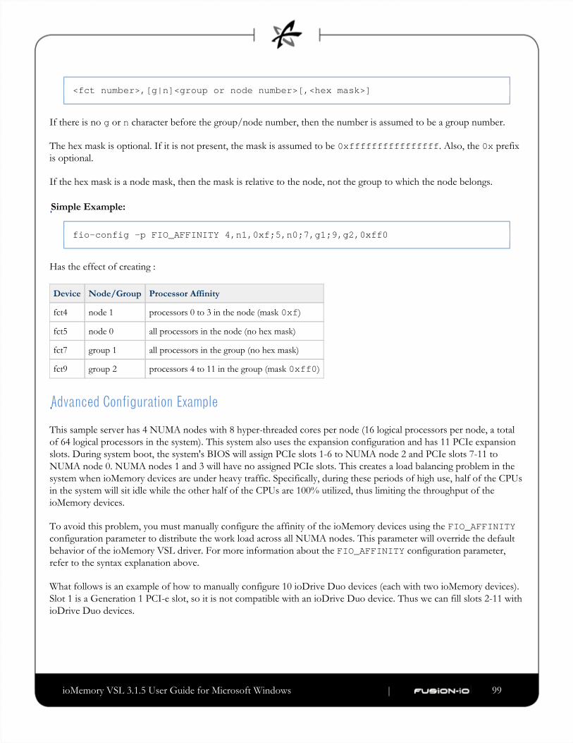
ioMemory VSL 3.1.5 User Guide for Microsoft Windows | __________________ ___ ___ 99
<fct number>,[g|n]<group or node number>[,<hex mask>]
If there is no or character before the group/node number, then the number is assumed to be a group number.g n
The hex mask is optional. If it is not present, the mask is assumed to be . Also, the prefix0xffffffffffffffff 0xis optional.
If the hex mask is a node mask, then the mask is relative to the node, not the group to which the node belongs.
Simple Example:
fio-config -p FIO_AFFINITY 4,n1,0xf;5,n0;7,g1;9,g2,0xff0
Has the effect of creating :
Device Node/Group Processor Affinity
fct4 node 1 processors 0 to 3 in the node (mask )0xf
fct5 node 0 all processors in the node (no hex mask)
fct7 group 1 all processors in the group (no hex mask)
fct9 group 2 processors 4 to 11 in the group (mask )0xff0
Advanced Configuration Example
This sample server has 4 NUMA nodes with 8 hyper-threaded cores per node (16 logical processors per node, a total
of 64 logical processors in the system). This system also uses the expansion configuration and has 11 PCIe expansion
slots. During system boot, the system's BIOS will assign PCIe slots 1-6 to NUMA node 2 and PCIe slots 7-11 to
NUMA node 0. NUMA nodes 1 and 3 will have no assigned PCIe slots. This creates a load balancing problem in the
system when ioMemory devices are under heavy traffic. Specifically, during these periods of high use, half of the CPUs
in the system will sit idle while the other half of the CPUs are 100% utilized, thus limiting the throughput of the
ioMemory devices.
To avoid this problem, you must manually configure the affinity of the ioMemory devices using the FIO_AFFINITYconfiguration parameter to distribute the work load across all NUMA nodes. This parameter will override the default
behavior of the ioMemory VSL driver. For more information about the configuration parameter,FIO_AFFINITYrefer to the syntax explanation above.
What follows is an example of how to manually configure 10 ioDrive Duo devices (each with two ioMemory devices).
Slot 1 is a Generation 1 PCI-e slot, so it is not compatible with an ioDrive Duo device. Thus we can fill slots 2-11 with
ioDrive Duo devices.
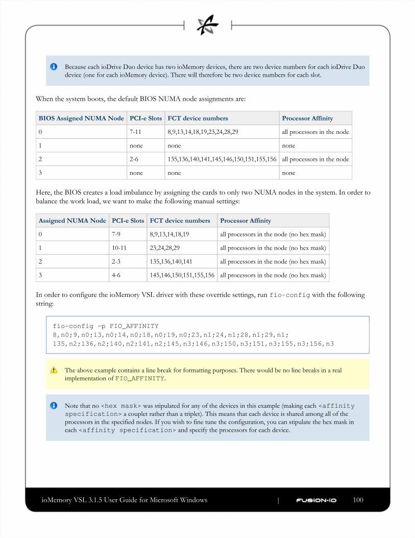
ioMemory VSL 3.1.5 User Guide for Microsoft Windows | __________________ ___ ___ 100
Because each ioDrive Duo device has two ioMemory devices, there are two device numbers for each ioDrive Duo
device (one for each ioMemory device). There will therefore be two device numbers for each slot.
When the system boots, the default BIOS NUMA node assignments are:
BIOS Assigned NUMA Node PCI-e Slots FCT device numbers Processor Affinity
0 7-11 8,9,13,14,18,19,23,24,28,29 all processors in the node
1 none none none
2 2-6 135,136,140,141,145,146,150,151,155,156 all processors in the node
3 none none none
Here, the BIOS creates a load imbalance by assigning the cards to only two NUMA nodes in the system. In order to
balance the work load, we want to make the following manual settings:
Assigned NUMA Node PCI-e Slots FCT device numbers Processor Affinity
0 7-9 8,9,13,14,18,19 all processors in the node (no hex mask)
1 10-11 23,24,28,29 all processors in the node (no hex mask)
2 2-3 135,136,140,141 all processors in the node (no hex mask)
3 4-6 145,146,150,151,155,156 all processors in the node (no hex mask)
In order to configure the ioMemory VSL driver with these override settings, run with the followingfio-configstring:
fio-config -p FIO_AFFINITY8,n0;9,n0;13,n0;14,n0;18,n0;19,n0;23,n1;24,n1;28,n1;29,n1;135,n2;136,n2;140,n2;141,n2;145,n3;146,n3;150,n3;151,n3;155,n3;156,n3
The above example contains a line break for formatting purposes. There would be no line breaks in a real
implementation of .FIO_AFFINITY
Note that no was stipulated for any of the devices in this example (making each <hex mask> <affinity a couplet rather than a triplet). This means that each device is shared among all of thespecification>
processors in the specified nodes. If you wish to fine tune the configuration, you can stipulate the hex mask in
each and specify the processors for each device.<affinity specification>

ioMemory VSL 3.1.5 User Guide for Microsoft Windows | __________________ ___ ___ 101
Checking the Log for Errors
If you enter a configuration that is not valid, then the settings will be disabled and an error will be available in the
system logs.
For example:
fio-config -p FIO_AFFINITY 5,g0,0xf;6,0xf
In this example, the affinity for device is set incorrectly, because there is no group/node number before thefct6mask. The following errors appear in the system log:
2011-09-09T12:22:15.176086800Z - ERROR - FusionEventDriver - FIO_AFFINITY:Invalid group or node number2011-09-09T12:22:15.176086800Z - ERROR - FusionEventDriver - InvalidFIO_AFFINITY parameter syntax at character 13: "5,g0,0xf;6,0x". Manualaffinity settings are disabled!

ioMemory VSL 3.1.5 User Guide for Microsoft Windows | __________________ ___ ___ 102
Appendix J- Upgrading Devices from VSL 2.x to 3.xThis version of the ioMemory VSL supports new features, including the latest generation of ioMemory architecture
and improved Flashback protection. These features require the latest version of the Fusion-io firmware. Every
ioMemory device in a system running 3.1.x or later must be upgraded to the latest version of the firmware.
For example, if you have a system running 2.3.1 ioMemory VSL with ioDrive devices previously installed, and you
want to install new ioDrive2 devices (that require the latest version of the firmware), then you will need to upgrade all
of the existing devices to the latest firmware version.
You cannot revert a device's firmware to an earlier version once you have upgraded the device (without voiding
your warranty). If you experience problems with your upgrade, please contact Customer Support at
Upgrading devices (previously configured for VSL 2.x.x) to work with VSL 3.x.x will require a low-level media
format of the device. No user data will be maintained during the process. Be sure to backup all data as instructed.
Upgrade Path
Depending on the current firmware version of your devices, you may need to upgrade your device's firmware
multiple times in order to preserve internal structures. The following is the minimum upgrade path that must be
followed. Upgrade the ioMemory VSL software on the system (and to the compatibleupgrade the firmware
version for each version of the software) in this order:
1.2.4 -> -> -> -> 1.2.7 2.1.0 2.3.1 3.1.x
For example, if your device is using the firmware for ioMemory VSL version 2.2.0, upgrade to 2.3.1
(both ioMemory VSL ) and then continue on the path. Visit and compatible firmwar
http://ts.fujitsu.com/support/ for all of the required software and firmware versions.
For more information on upgrading from one version to the next, see the (available at ioMemory VSL Release Notes
http://ts.fujitsu.com/support/) for the version you will upgrade the device to. Then follow the upgrade instructions in that ve rsion's user guide for your operating system (including the firmware update instructions).

ioMemory VSL 3.1.5 User Guide for Microsoft Windows | __________________ ___ ___ 103
1.
a.
b.
c.
2.
a.
b.
c.
d.
e.
Upgrade Procedure
Be sure to follow the upgrade path listed above. Make sure that all previously installed ioDrive devices are updated
with the appropriate 2.3.1-compatible firmware.
If you plan to use ioDrive devices and ioDrive2 devices in the same host, perform this upgrade on all existing
ioDrive devices installing the new ioDrive2 devices.before
Prepare each existing ioDrive device for upgrade.
Backup user data on each ioDrive device.
The upgrade process will require a low-level media format of the device. No user data will be
maintained during the process; be sure to make a complete backup.
Use a backup method of your choice. For best results, use software and backup devices that have proven
effective in the past. Do not backup the data onto another ioMemory device on the same system. The
back up must be to a local disk or to an externally attached volume.
Run the command-line utility and save the output. This will capture the devicefio-bugreportinformation for each device in the system. This device information will be useful in troubleshooting any
upgrade issues. Sample command:
fio-bugreport
Detach ioDrive devices, for example:
fio-detach /dev/fct*
For more information, see fio-detach
Uninstall the 2.x ioMemory VSL software
Go to > .Start Control Panel
Click .Programs & Files
Select the ioMemory VSL (Fusion-io) entry.
Click .Uninstall
Restart the computer.

ioMemory VSL 3.1.5 User Guide for Microsoft Windows | __________________ ___ ___ 104
3.
a.
b.
c.
d.
e.
f.
4.
Install the new VSL.
Download the ioMemory VSL installation program for Windows at http://ts.fujitsu.com/support/
Run the ioMemory VSL installation program. The installation program presents a custom setup
tree-view with options for installation.
Mouse over a component in the tree view to see its description.
Click .Next
To select a different folder for the installation, browse to the folder and click . The default folder is OK
.C:\Program Files\Fusion-io ioMemory VSL
The uninstaller file is placed in the root of the Fusion-io ioMemory VSL (default install folder).
Follow the onscreen prompts to complete the install.
Choose on the finish screen of the installer.Reboot Now
For full installation instructions, see .Existing ioMemory VSL Installation
Update the firmware on each device to the latest version using .fio-update-iodrive
Prevent Power Loss
Take measures to prevent power loss during the update, such as a UPS. Power loss during an update may
result in device failure. For all warnings, alerts, and options pertaining to this utility, see the
utility reference in the appendix.fio-update-iodrive
Sample syntax:
fio-update-iodrive <iodrive_version.fff>
Where is the path to the firmware archive (the default file path is <iodrive_version.fff> C:\Program). This command will updateFiles\Fusion-io ioMemory VSL\Firmware\iodrive_<version>.fff
all of the devices to the selected firmware. If you wish to update specific devices, consult the utility reference
for more options.

ioMemory VSL 3.1.5 User Guide for Microsoft Windows | __________________ ___ ___ 105
5.
6.
7.
8.
Reboot the system
If run, will warn that the upgraded devices are missing a lebmap. This is expected, and willfio-statusbe fixed in the next step.
Destructive Step
Running in the next step will erase the entire device, including user data. Once this formatfio-formatis started, the device cannot be downgraded to the 2.x driver without voiding your warranty. If you
experience problems with your upgrade, please contact Customer Support at [email protected]
Format each device using , for example:fio-format
fio-format <device>
You will be prompted to confirm you wish to erase all data on the device.
The format may take an extended period of time, depending on the wear on the device.
Attach all ioDrive devices, for example:
fio-attach /dev/fct*
Check the status of all devices using fio-status, for example:
fio-status -a
Your ioDrive devices have now been successfully upgraded for this version of the ioMemory VSL. You may now
install any ioDrive2 devices.

ioMemory VSL 3.1.5 User Guide for Microsoft Windows | __________________ ___ ___ 106
Appendix K- Documentation PermissionsThe and the file, which ship in binary form with the driver, contain content that have theAVR bootloader tree.hfollowing documentation copyright requirements:
AVR Bootloader
Copyright © 2002, 2003, 2004, 2005, 2006, 2007 Eric B. Weddington
All rights reserved.
Redistribution and use in source and binary forms, with or without modification, are permitted provided that the
following conditions are met:
Redistributions of source code must retain the above copyright notice, this list of conditions and the following
disclaimer.
Redistributions in binary form must reproduce the above copyright notice, this list of conditions and the
following disclaimer in the documentation and/or other materials provided with the distribution.
Neither the name of the copyright holders nor the names of contributors may be used to endorse or promote
products derived from this software without specific prior written permission.
THIS SOFTWARE IS PROVIDED BY THE COPYRIGHT HOLDERS AND CONTRIBUTORS "AS IS" AND
ANY EXPRESS OR IMPLIED WARRANTIES, INCLUDING, BUT NOT LIMITED TO, THE IMPLIED
WARRANTIES OF MERCHANTABILITY AND FITNESS FOR A PARTICULAR PURPOSE ARE
DISCLAIMED. IN NO EVENT SHALL THE COPYRIGHT OWNER OR CONTRIBUTORS BE LIABLE FOR
ANY DIRECT, INDIRECT, INCIDENTAL, SPECIAL, EXEMPLARY, OR CONSEQUENTIAL DAMAGES
(INCLUDING, BUT NOT LIMITED TO, PROCUREMENT OF SUBSTITUTE GOODS OR SERVICES; LOSS
OF USE, DATA, OR PROFITS; OR BUSINESS INTERRUPTION) HOWEVER CAUSED AND ON ANY
THEORY OF LIABILITY, WHETHER IN CONTRACT, STRICT LIABILITY, OR TORT (INCLUDING
NEGLIGENCE OR OTHERWISE) ARISING IN ANY WAY OUT OF THE USE OF THIS SOFTWARE,
EVEN IF ADVISED OF THE POSSIBILITY OF SUCH DAMAGE.
tree.h
Copyright 2002 Niels Provos <[email protected]>
All rights reserved.
Redistribution and use in source and binary forms, with or without modification, are permitted provided that the

ioMemory VSL 3.1.5 User Guide for Microsoft Windows | __________________ ___ ___ 107
1.
2.
following conditions are met:
Redistributions of source code must retain the above copyright notice, this list of conditions and the following
disclaimer.
Redistributions in binary form must reproduce the above copyright notice, this list of conditions and the
following disclaimer in the documentation and/or other materials provided with the distribution.
THIS SOFTWARE IS PROVIDED BY THE AUTHOR "AS IS" AND ANY EXPRESS OR
IMPLIED WARRANTIES, INCLUDING, BUT NOT LIMITED TO, THE IMPLIED WARRANTIES OF
MERCHANTABILITY AND FITNESS FOR A PARTICULAR PURPOSE ARE DISCLAIMED. IN NO EVENT
SHALL THE AUTHOR BE LIABLE FOR ANY DIRECT, INDIRECT, INCIDENTAL, SPECIAL,
EXEMPLARY, OR CONSEQUENTIAL DAMAGES (INCLUDING, BUT NOT LIMITED TO,
PROCUREMENT OF SUBSTITUTE GOODS OR SERVICES; LOSS OF USE, DATA, OR PROFITS; OR
BUSINESS INTERRUPTION) HOWEVER CAUSED AND ON ANY THEORY OF LIABILITY, WHETHER
IN CONTRACT, STRICT LIABILITY, OR TORT (INCLUDING NEGLIGENCE OR OTHERWISE) ARISING
IN ANY WAY OUT OF THE USE OF THIS SOFTWARE, EVEN IF ADVISED OF THE POSSIBILITY OF
SUCH DAMAGE.

ioMemory VSL 3.1.5 User Guide for Microsoft Windows ___________________________
Fusion Powered SupportWe offer ioDrive Customer Support by phone, e-mail and on the Web.
Please use the contact form at:http://support.ts.fujitsu.com/contact/ For the Japanese market, please use the following URL: http://primeserver.fujitsu.com/primergy/support/ Telephone Support
For customer support phone numbers, please refer to the Fujitsu TechnologySolutions service desk at http://ts.fujitsu.com/support/servicedesk.html For the Japanese market, please use the following URL: http://primeserver.fujitsu.com/primergy/support/supportdesk.html
Web
It is recommended to use the latest firmware / driver / BIOS versions on servers and components. Software packages are available for download at : http://support.ts.fujitsu.com > Server > Drivers & Downloads For the Japanese market, please use the following URL: http://primeserver.fujitsu.com/primergy/downloads Corresponding user documentation for servers and optional components can be found online athttp://manuals.ts.fujitsu.com > Industry Standard Servers > Expansion Cards > PCIe SSD Cardsor on the ServerView Suite Documentation DVD. For the Japanese market, please use the following URL: http://primeserver.fujitsu.com/primergy/manual.html