used fuel disposition campaign gap analysis to support
TRANSCRIPT

USED FUEL DISPOSITION CAMPAIGN
Gap Analysis to Support Extended Storage of Used Nuclear Fuel
Rev. 0
Prepared for
U.S. Department of Energy
Used Fuel Disposition Campaign
Brady Hanson (PNNL)
Halim Alsaed (INL)
Christine Stockman (SNL)
David Enos (SNL)
Ryan Meyer (PNNL)
Ken Sorenson (SNL)
January 31, 2012 FCRD-USED-2011-000136 Rev. 0
PNNL-20509

USED FUEL DISPOSITION CAMPAIGN Gap Analysis to Support Extended Storage of Used Nuclear Fuel Rev. 0
ii JANUARY 31, 2012
Disclaimer
This information was prepared as an account of work sponsored by an
agency of the U.S. Government. Neither the U.S. Government nor any
agency thereof, nor any of their employees, makes any warranty, expressed
or implied, or assumes any legal liability or responsibility for the accuracy,
completeness, or usefulness, of any information, apparatus, product, or
process disclosed or represents that its use would not infringe privately
owned rights. References herein to any specific commercial product,
process, or service by trade name, trade mark, manufacturer, or otherwise,
does not necessarily constitute or imply its endorsement, recommendation,
or favoring by the U.S. Government or any agency thereof. The views and
opinions of the authors expressed herein do not necessarily state or reflect
those of the U.S. Government or any agency thereof.

USED FUEL DISPOSITION CAMPAIGN Gap Analysis to Support Extended Storage of Used Nuclear Fuel Rev. 0
January 31, 2012 iii
Reviewed by:
Steven C. Marschman (Idaho National Laboratory)
Technical Reviewer
Ken B. Sorenson (Sandia National Laboratories)
Storage and Transportation Control Account Manager
Submitted by:
Brady Hanson (Pacific Northwest National Laboratory)
R&D Investigations Team Lead

USED FUEL DISPOSITION CAMPAIGN Gap Analysis to Support Extended Storage of Used Nuclear Fuel Rev. 0
iv January 31, 2012
USED FUEL DISPOSITION CAMPAIGN Gap Analysis to Support Extended Storage of Used Nuclear Fuel Rev. 0
January 31, 2012 v
EXECUTIVE SUMMARY
This report fulfills the M1 milestone M11UF041401, “Storage R&D Opportunities Report”
under Work Package Number FTPN11UF0414.
The U.S. Department of Energy Office of Nuclear Energy (DOE-NE), Office of Fuel Cycle
Technology, has established the Used Fuel Disposition Campaign (UFDC) to conduct the
research and development activities related to storage, transportation, and disposal of used
nuclear fuel and high-level radioactive waste. The mission of the UFDC is to identify
alternatives and conduct scientific research and technology development to enable storage,
transportation and disposal of used nuclear fuel (UNF) and wastes generated by existing and
future nuclear fuel cycles. The Storage and Transportation staff within the UFDC are
responsible for addressing issues regarding the extended or long-term storage of UNF and its
subsequent transportation. The near-term objectives of the Storage and Transportation task are
to use a science-based approach to develop the technical bases to support the continued safe and
secure storage of UNF for extended periods, subsequent retrieval, and transportation.
While both wet and dry storage have been shown to be safe options for storing UNF, the focus of
the program is on dry storage at reactor or centralized locations. Although the initial emphasis of
the program is on commercial light-water reactor uranium-oxide fuel, DOE-owned research and
defense used nuclear fuels as well as alternative and advanced fuel concepts being investigated
by the DOE will be addressed later in this program. Because limited information is available on
the properties of high burnup fuel (exceeding 45 gigawatt-days per metric tonne of uranium
[GWd/MTU]), and because much of the fuel currently discharged from today’s reactors exceeds
this burnup threshold, a particular emphasis of this program is on high burnup fuels.
Until a disposition pathway, e.g., recycling or geologic disposal, is chosen and implemented, the
storage periods for UNF will likely be longer than were originally intended. The ability of the
important-to-safety structures, systems, and components (SSCs) to continue to meet safety
functions over extended times must be determined and demonstrated. In addition, the ability of
these SSCs to meet applicable safety functions when the used nuclear fuel is transported must be
ensured. To facilitate all options for disposition and to maintain retrievability and normal back-
end operations, it is considered an important objective of this program to evaluate the likelihood
that the used nuclear fuel remains undamaged after extended storage. This does not preclude
consideration of other options, such as canning of all UNF, from a total systems perspective to
determine overall benefit to nuclear waste management.
This report documents the initial gap analysis performed to identify data and modeling needs to
develop the desired technical bases to enable the extended storage of UNF. For most SSCs
important to safety, additional data are required, often because there are limited data on the new
materials used in more modern fuels or dry storage cask systems or because the effects of high
burnup and extended storage are not fully known. Based upon the importance of the SSC to
licensing a dry storage system or an independent spent fuel storage installation (ISFSI), the
potential effects of extended storage or high burnup on the degradation mechanism, and a
combination of the data needs, regulatory considerations, likelihood of occurrence, the
USED FUEL DISPOSITION CAMPAIGN Gap Analysis to Support Extended Storage of Used Nuclear Fuel Rev. 0
vi January 31, 2012
consequence of degradation, the means to remediate the degradation, and the impact of
degradation on cost, operations, and future waste management strategies, a research and
development (R&D) priority (Low, Medium, or High) is assigned. The R&D priority cannot be
higher than the ranking assigned for importance to licensing; obviously, a structure, system, or
component ranked of Low importance to licensing does not require a Medium or High priority
for R&D. However, a structure, system, or component can be of High importance to licensing,
but the R&D needs can be lower depending on the prioritization criteria.
The degradation mechanisms identified in this report are limited to those during normal dry
storage operations and potential off-normal conditions. Impacts of degradation mechanisms on
demonstrating compliance with design basis accidents including those initiated by natural
phenomena are not discussed in this report. This report is meant to be a living document that
will be updated as additional technical data become available and as policy decisions are
implemented. Future revisions will include formulating the technical bases for consideration of
accidents and natural phenomena during extended dry storage. In addition, future revisions will
compare the gap analysis generated as part of the UFDC with similar analyses developed by the
U.S. Nuclear Waste Technical Review Board, the U.S. Nuclear Regulatory Commission, Electric
Power Research Institute, and international organizations. A similar gap analysis effort is under
way as part of the UFDC to examine the needs to meet transportation requirements. Once the
transportation work is completed, the results will be consolidated in a consistent manner in a
revision to this report to form a single set of gaps and congruous direction for addressing these
gaps to meet applicable storage and transportation requirements.
There are several cross-cutting needs for dry storage. These cross-cutting needs are key to
detecting, understanding, and evaluating the extent of many of the degradation mechanisms, as
well as both determining and validating alternate means of demonstrating compliance with
specific regulatory requirements. Table S-1 provides a summary of cross-cutting needs and the
proposed work to address those needs.

USED FUEL DISPOSITION CAMPAIGN Gap Analysis to Support Extended Storage of Used Nuclear Fuel Rev. 0
January 31, 2012 vii
Table S-1. Summary of Cross-Cutting Needs
Cross-Cutting
Need
Description
Importance
of R&D
Approach to
Closing Gap
Monitoring
Continued efficacy or acceptable performance of
dry storage systems for relatively short-term
storage can be demonstrated through accelerated
tests to validate models and analyses. However,
for extended storage, projection of continued
efficacy or acceptable performance may not be
possible without collecting data to validate the
models developed using data from short-term
tests. To collect the necessary data as part of the
R&D program and engineering-scale
demonstration, more effective monitoring
systems must be developed to detect failures (or
precursors to those failures) and to evaluate
materials property changes that can be correlated
to their structural performance.
High Develop systems
for early detection
of confinement
boundary
degradation,
monitoring cask
environmental
changes, and data
transmission
without
compromising cask
or canister
boundary.
Medium Develop systems
for early detection
of corrosion of
metal
reinforcement.
Temperature
Profiles Most degradation mechanisms are temperature-
dependent with rates generally increasing with
temperature. Current safety analyses are
appropriately based on bounding temperature
profiles, but recent data has shown that high
burn up cladding can become brittle at lower
temperatures due to phenomena such as radial
hydride precipitation. Similarly, recent models
on delayed hydride cracking suggest that this
mechanism may become more prolific at lower
temperatures. For these reasons, the program
recognizes the need to develop realistic
temperature profiles for all dry storage
components as a function of extended storage.
High Calculate
temperature profiles
of SSCs as a
function of time for
representative dry
cask storage
systems.
USED FUEL DISPOSITION CAMPAIGN Gap Analysis to Support Extended Storage of Used Nuclear Fuel Rev. 0
viii January 31, 2012
Table S-1. (contd)
Cross-Cutting
Need
Description
Importance
of R&D
Approach to
Closing Gap
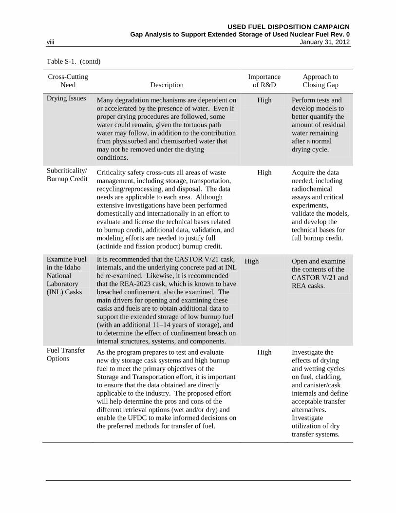
Drying Issues Many degradation mechanisms are dependent on
or accelerated by the presence of water. Even if
proper drying procedures are followed, some
water could remain, given the tortuous path
water may follow, in addition to the contribution
from physisorbed and chemisorbed water that
may not be removed under the drying
conditions.
High Perform tests and
develop models to
better quantify the
amount of residual
water remaining
after a normal
drying cycle.
Subcriticality/
Burnup Credit Criticality safety cross-cuts all areas of waste
management, including storage, transportation,
recycling/reprocessing, and disposal. The data
needs are applicable to each area. Although
extensive investigations have been performed
domestically and internationally in an effort to
evaluate and license the technical bases related
to burnup credit, additional data, validation, and
modeling efforts are needed to justify full
(actinide and fission product) burnup credit.
High Acquire the data
needed, including
radiochemical
assays and critical
experiments,
validate the models,
and develop the
technical bases for
full burnup credit.
Examine Fuel
in the Idaho
National
Laboratory
(INL) Casks
It is recommended that the CASTOR V/21 cask,
internals, and the underlying concrete pad at INL
be re-examined. Likewise, it is recommended
that the REA-2023 cask, which is known to have
breached confinement, also be examined. The
main drivers for opening and examining these
casks and fuels are to obtain additional data to
support the extended storage of low burnup fuel
(with an additional 11–14 years of storage), and
to determine the effect of confinement breach on
internal structures, systems, and components.
High Open and examine
the contents of the
CASTOR V/21 and
REA casks.
Fuel Transfer
Options As the program prepares to test and evaluate
new dry storage cask systems and high burnup
fuel to meet the primary objectives of the
Storage and Transportation effort, it is important
to ensure that the data obtained are directly
applicable to the industry. The proposed effort
will help determine the pros and cons of the
different retrieval options (wet and/or dry) and
enable the UFDC to make informed decisions on
the preferred methods for transfer of fuel.
High Investigate the
effects of drying
and wetting cycles
on fuel, cladding,
and canister/cask
internals and define
acceptable transfer
alternatives.
Investigate
utilization of dry
transfer systems.

USED FUEL DISPOSITION CAMPAIGN Gap Analysis to Support Extended Storage of Used Nuclear Fuel Rev. 0
January 31, 2012 ix
Table S-2 provides a summary of the SSCs important to safety, the degradation mechanisms to
which either a Medium or a High priority for additional R&D were assigned, and the proposed
approach for closing these gaps. Proposed approaches for closing some of the gaps for
degradation mechanisms assigned a Low priority are discussed in this report but are not included
in the summary tables. The gaps assigned a Low priority will be addressed in future years as
resources allow, or if their priority changes as more information becomes available. A future
report will document the details of the proposed testing and modeling to close the identified
gaps. In addition to proposed specific testing and modeling plans, the report will also include the
necessary quality assurance requirements and implementation plans.
A brief discussion on how each of the Medium or High priority gaps may be addressed is
provided in this report. The discussion is meant to be a high-level approach of whether
experimental work, analyses, modeling and simulation, detailed aging management plans, or a
combination of these approaches is needed. Detailed discussions of specific means for
addressing the data gaps and their prioritization of importance to the UFDC will be provided in a
fiscal year 2012 document. It is envisioned that the gaps will be closed by obtaining data
through separate effects tests, modeling and simulation, small scale tests, and in-service
inspections. The predictive models developed through this effort will be validated through a
long-term engineering-scale demonstration of high burnup fuel in full-scale casks/canisters. The
proposed tasks are essential to ensuring timely, cost-effective, and defensible approaches to
consolidating used nuclear fuel that is currently stored at “ISFSI Only” sites and to facilitating
licensing and license extensions of high burnup fuel and associated dry cask storage systems.
Table S-2. Summary of High- and Medium-Priority Degradation Mechanisms That Could Impact
the Performance of Structures, Systems, and Components (SSCs) During Extended Storage
SSC
Degradation
Mechanism
Importance
of R&D
Approach to Closing Gaps
Cladding
Annealing of
radiation damage
Medium Long-term, low temperature annealing will be analyzed
through advanced modeling and simulation with some
experimental work to support the model.
H2 effects:
embrittlement and
reorientation
High A comprehensive experimental and modeling program
to examine the factors that influence hydride
reorientation will be performed, with a focus on new
cladding materials and high burnup fuels. Additional
experimentation and modeling to provide the link
between unirradiated and irradiated cladding
performance will be initiated.
H2 effects: delayed
hydride cracking
High Experimental work combined with modeling will be
initiated.
Oxidation Medium Experimental work to determine the mechanism for the
rapid cladding oxidation observed will be initiated.
Creep Medium Long-term, low-temperature, low-strain creep will be
analyzed through advanced modeling and simulation
with some experimental work to support the model.

USED FUEL DISPOSITION CAMPAIGN Gap Analysis to Support Extended Storage of Used Nuclear Fuel Rev. 0
x January 31, 2012
Table S-2. (contd)
SSC
Degradation
Mechanism
Importance
of R&D
Approach to Closing Gaps
Fuel
Assembly
Hardware
Corrosion (stress
corrosion cracking)
Medium Because the fuel assembly hardware components of
concern are the same or similar to those that also serve
as a cladding, the results of cladding tests and analyses
will be utilized.
Neutron
Poisons
Thermal aging
effects
Medium Development of an accurate source term and radiation
and thermal profiles is needed. Experimental work and
modeling together in collaboration with universities
under the Nuclear Energy University Program (NEUP)
will be initiated.
Creep Medium
Embrittlement and
cracking
Medium
Corrosion
(blistering)
Medium
Container
(Welded
Canister)
Atmospheric
corrosion
(including marine
environment)
High
Analyses of the conditions that will exist on the cask
and canister surfaces will be performed. Collaboration
with the Electric Power Research Institute (EPRI) -led
Extended Storage Collaboration Program (ESCP) and
International Subcommittee, especially the Japanese
Central Research Institute of Electric Power Industry
(CRIEPI) and the German Federal Institute for
Materials Research and Testing (BAM), will be
initiated.
Aqueous corrosion High
Container
(Bolted
Casks)
Thermomechanical
fatigue of seals and
bolts
Medium
Atmospheric
corrosion
(including marine
environment)
High
Aqueous corrosion High
Overpack
Freeze–thaw Medium Development of detailed aging management programs
will be performed. Inspection tasks to provide the
means for early detection will be initiated. Corrosion of
embedded steel
Medium

USED FUEL DISPOSITION CAMPAIGN Gap Analysis to Support Extended Storage of Used Nuclear Fuel Rev. 0
January 31, 2012 xi
The UFDC is actively pursuing collaborations to help address the data gaps in a timely and cost-
effective manner. These collaborations include the various university groups working on these
issues as part of the DOE Nuclear Energy University Program. The UFDC is also an active
participant in the EPRI-led Extended Storage Collaboration Program, which was formed in
November 2009 and consists of industry, regulators, and national laboratories bringing together a
wide range of perspectives and technical expertise to address objectives similar to those of the
Storage and Transportation task. The Extended Storage Collaboration Program also includes an
international subcommittee chaired by the Storage and Transportation manager. The goals of
this subcommittee are to identify the gap analyses in each of the participating countries
(currently the United States, United Kingdom, Spain, Germany, Hungary, Japan, and South
Korea), identify commonalities, and collaborate to address these data gaps.
USED FUEL DISPOSITION CAMPAIGN Gap Analysis to Support Extended Storage of Used Nuclear Fuel Rev. 0
xii January 31, 2012
ACKNOWLEDGMENTS
The authors acknowledge and thank the many people who contributed to this report, both those
named here and any others who have been a part of this effort.
First, we thank our U.S. Department of Energy Office of Nuclear Energy (DOE-NE) sponsors:
Siegfried Stockinger, DOE-NE-53 Technical Lead, Engineered Systems Team; Timothy Gunter,
DOE-NE-53 Lead, Engineered Systems Team; Ned Larson, DOE-NE-53 Lead, Natural Systems
Team; John Orchard, DOE-NE-53 Lead, Transportation; Jeff Williams, DOE-NE-53 Assistant
Director, Office of Used Nuclear Fuel Disposition R&D, and William Boyle, DOE-NE-53
Director, Office of Used Nuclear Fuel Disposition R&D.
We also thank the Used Fuel Disposition Campaign management: Peter Swift, National
Technical Director; Mark Nutt, Deputy National Technical Director; and Ken Sorenson,
Manager, Storage and Transportation.
We thank Steven C. Marschman and INL for the technical review.
Technical contributors to, and reviewers of, this report include all those listed below:
Argonne National Laboratory:
Michael C. Billone
Omesh K. Chopra
James C. Cunnane
Yung Liu
Han-Chung Tsai
Idaho National Laboratory:
Sandra M. Birk
Brett W. Carlsen
Philip Winston
Los Alamos National Laboratory:
Timothy J. Ulrich II
Lawrence Livermore National Laboratory:
Jim Blink
Wayne King
William Halsey
Oak Ridge National Laboratory:
Jeremy T. Busby
David E. Holcombe
Rob L. Howard
John M. Scaglione
John C. Wagner
Yong Yan
Pacific Northwest National Laboratory:
Harold E. Adkins
Carl E. Beyer
James L. Buelt
Judith M. Cuta
Ken J. Geelhood
Charles H. Henager
Curt A. Lavender
Robert O. Montgomery
Pradeep Ramuhalli
Sandia National Laboratories:
Laurence H. Brush
Cathy Ottinger Farnum
Ruth F. Weiner
Savannah River National Laboratory
Natraj Iyer
Ronald Kesterson
Adrian Mendez-Torres
Dennis W. Vinson
We thank the PNNL technical communications specialists Andrea J. Currie and Cornelia Brim
(editing), and Kathy Neiderhiser and Susan Tackett (document production).

USED FUEL DISPOSITION CAMPAIGN Gap Analysis to Support Extended Storage of Used Nuclear Fuel Rev. 0
January 31, 2012 xiii
CONTENTS
EXECUTIVE SUMMARY .......................................................................................................................... v
ACKNOWLEDGMENTS .......................................................................................................................... xii
ACRONYMS ........................................................................................................................................... xviii
1. INTRODUCTION .............................................................................................................................. 1
1.1 Background .............................................................................................................................. 2 1.1.1 Dry Storage History and Regulation ........................................................................... 2 1.1.2 Current Status .............................................................................................................. 4 1.1.3 ISFSI Only Storage Sites ............................................................................................ 7 1.1.4 High Burnup Issue ...................................................................................................... 8 1.1.5 Dry Storage and Transportation Systems Issues ......................................................... 9
1.2 Scope ...................................................................................................................................... 10
2. DRY STORAGE .............................................................................................................................. 13
2.1 Dry Cask Storage Demonstration Projects ............................................................................. 13 2.1.1 Nevada Test Site ....................................................................................................... 13 2.1.2 Surry Power Station .................................................................................................. 13 2.1.3 H.B. Robinson Nuclear Plant .................................................................................... 15 2.1.4 Idaho National Engineering Laboratory .................................................................... 16 2.1.5 Private Fuel Storage .................................................................................................. 19
2.2 Dry Storage Casks .................................................................................................................. 19 2.2.1 Transnuclear, Inc. ...................................................................................................... 23 2.2.2 Holtec International................................................................................................... 25 2.2.3 NAC International, Inc. ............................................................................................. 27
2.3 Regulation and Guidance of UNF Storage ............................................................................. 28 2.3.1 Regulation ................................................................................................................. 28 2.3.2 Review Plans ............................................................................................................. 30 2.3.3 Interim Staff Guidance .............................................................................................. 30 2.3.4 Additional Guidance Documents .............................................................................. 32
2.4 Application of Regulatory Requirements and Guidance ........................................................ 33 2.4.1 Dry Storage Systems SSCs and Safety Functional Areas ......................................... 33 2.4.2 Retrievability (Including Thermal Performance) ...................................................... 34 2.4.3 Confinement .............................................................................................................. 36 2.4.4 Radiation Protection .................................................................................................. 37 2.4.5 Subcriticality ............................................................................................................. 38
3. METHODOLOGY ........................................................................................................................... 41
3.1 Analysis Conditions ............................................................................................................... 41
3.2 Stressors ................................................................................................................................. 44 3.2.1 Thermal Stressors ...................................................................................................... 44 3.2.2 Radiation Stressors .................................................................................................... 44 3.2.3 Chemical Stressors .................................................................................................... 45 3.2.4 Mechanical Stressors................................................................................................. 45
3.3 Data Gap Analysis Approach ................................................................................................. 45

USED FUEL DISPOSITION CAMPAIGN Gap Analysis to Support Extended Storage of Used Nuclear Fuel Rev. 0
xiv January 31, 2012
3.3.1 Basis for Research and Development Priorities ........................................................ 46
4. CROSS-CUTTING NEEDS ............................................................................................................. 49
4.1 Temperature Profiles .............................................................................................................. 49
4.2 Drying Issues.......................................................................................................................... 50
4.3 Subcriticality .......................................................................................................................... 52 4.3.1 Introduction ............................................................................................................... 52 4.3.2 Burnup Credit ............................................................................................................ 53 4.3.3 Moderator Exclusion ................................................................................................. 54
4.4 Examination of the Idaho National Laboratory Casks and Fuel ............................................ 56
4.5 Fuel Transfer Options ............................................................................................................ 57
4.6 Monitoring ............................................................................................................................. 58 4.6.1 Introduction ............................................................................................................... 59 4.6.2 Relevant Aging/Degradation Mechanisms ............................................................... 59 4.6.3 Sensing Systems ........................................................................................................ 62 4.6.4 R&D Priorities for Monitoring ................................................................................. 68
5. GAP ANALYSES ............................................................................................................................ 71
5.1 Fuel ........................................................................................................................................ 72 5.1.1 Introduction ............................................................................................................... 72 5.1.2 Analysis of Safety Functions .................................................................................... 73 5.1.3 Discussion of Selected Fuel Issues ........................................................................... 74 5.1.4 Fuel Summary Table ................................................................................................. 80 5.1.5 Approach to Closing Fuel Gaps ................................................................................ 81
5.2 Cladding ................................................................................................................................. 81 5.2.1 Introduction ............................................................................................................... 81 5.2.2 Analysis of Safety Functions .................................................................................... 83 5.2.3 Discussion of Selected Cladding Issues .................................................................... 84 5.2.4 Cladding Summary Table ....................................................................................... 107 5.2.5 Approach to Closing Cladding Gaps....................................................................... 107
5.3 Assembly Hardware ............................................................................................................. 107 5.3.1 Introduction ............................................................................................................. 107 5.3.2 Analysis of Safety Functions .................................................................................. 108 5.3.3 Discussion of Selected Assembly Hardware Issues ................................................ 110 5.3.4 Hardware Summary Table ...................................................................................... 114 5.3.5 Approach to Closing Assembly Hardware Gaps .................................................... 114
5.4 Fuel Baskets ......................................................................................................................... 115 5.4.1 Introduction ............................................................................................................. 115 5.4.2 Analysis of Safety Functions .................................................................................. 115 5.4.3 Discussion of Selected Basket Issues ...................................................................... 116 5.4.4 Fuel Baskets Summary Table ................................................................................. 119 5.4.5 Approach to Closing Fuel Baskets Gaps ................................................................. 119
5.5 Neutron Poisons ................................................................................................................... 119 5.5.1 Introduction ............................................................................................................. 119 5.5.2 Analysis of Safety Functions .................................................................................. 121 5.5.3 Discussion of Selected Neutron Poison Issues ........................................................ 122 5.5.4 Neutron Poisons Summary Table ........................................................................... 129

USED FUEL DISPOSITION CAMPAIGN Gap Analysis to Support Extended Storage of Used Nuclear Fuel Rev. 0
January 31, 2012 xv
5.5.5 Approach to Closing Neutron Poisons Gaps ........................................................... 130
5.6 Neutron Shields .................................................................................................................... 130 5.6.1 Introduction ............................................................................................................. 130 5.6.2 Analysis of Safety Functions .................................................................................. 131 5.6.3 Discussion of Neutron Shields Issues ..................................................................... 131 5.6.4 Neutron Shields Summary Table ............................................................................ 135 5.6.5 Approach to Closing Neutron Shields Gaps ........................................................... 135
5.7 Container (Base Metal, Closure Welds, Bolts, and Seals) ................................................... 135 5.7.1 Introduction ............................................................................................................. 135 5.7.2 Analysis of Safety Functions .................................................................................. 136 5.7.3 Discussion of Selected Container Issues ................................................................. 137 5.7.4 Container Summary Table ...................................................................................... 148 5.7.5 Approach to Closing Container Gaps ..................................................................... 149
5.8 Overpack/Storage Module for Canistered Fuel .................................................................... 149 5.8.1 Introduction ............................................................................................................. 149 5.8.2 Analysis of Safety Functions .................................................................................. 149 5.8.3 Discussion of Selected Concrete Overpack Issues .................................................. 150 5.8.4 Overpack Summary Table ...................................................................................... 161 5.8.5 Approach to Closing Overpack Gaps ...................................................................... 162
5.9 Pad ........................................................................................................................................ 162 5.9.1 Introduction ............................................................................................................. 162 5.9.2 Analysis of Safety Functions .................................................................................. 162 5.9.3 Discussion of Selected Pad Issues........................................................................... 162 5.9.4 Pad Summary Table ................................................................................................ 163 5.9.5 Approach to Closing Pad Gaps ............................................................................... 163
6. CONCLUSIONS ............................................................................................................................ 165
6.1 Cross-Cutting Needs ............................................................................................................ 165 6.1.1 Monitoring .............................................................................................................. 165 6.1.2 Temperature Profiles ............................................................................................... 167 6.1.3 Drying Issues .......................................................................................................... 167 6.1.4 Subcriticality ........................................................................................................... 167 6.1.5 Examine Fuel in INL Casks .................................................................................... 168 6.1.6 Fuel Retrieval Options ............................................................................................ 168
6.2 High- and Medium-Priority Degradation Mechanisms ........................................................ 168
6.3 Path Forward ........................................................................................................................ 170
7. REFERENCES ............................................................................................................................... 173
APPENDIX A Independent Spent Fuel Storage Installations in the United States by License Date ...... 189
APPENDIX B Dry Cask Storage in the United States by Vendor .......................................................... 195

USED FUEL DISPOSITION CAMPAIGN Gap Analysis to Support Extended Storage of Used Nuclear Fuel Rev. 0
xvi January 31, 2012
FIGURES
1-1. Locations of Operating Commercial Nuclear Power Reactors .............................................. 5
1-2. Historical and Projected Discharges of Used Nuclear Fuel, 1986–2020 ............................... 6
1-3. Locations of Independent Spent Fuel Storage Installations ................................................... 7
1-4. Historical and Projected Average PWR and BWR Discharge Burnups ................................. 9
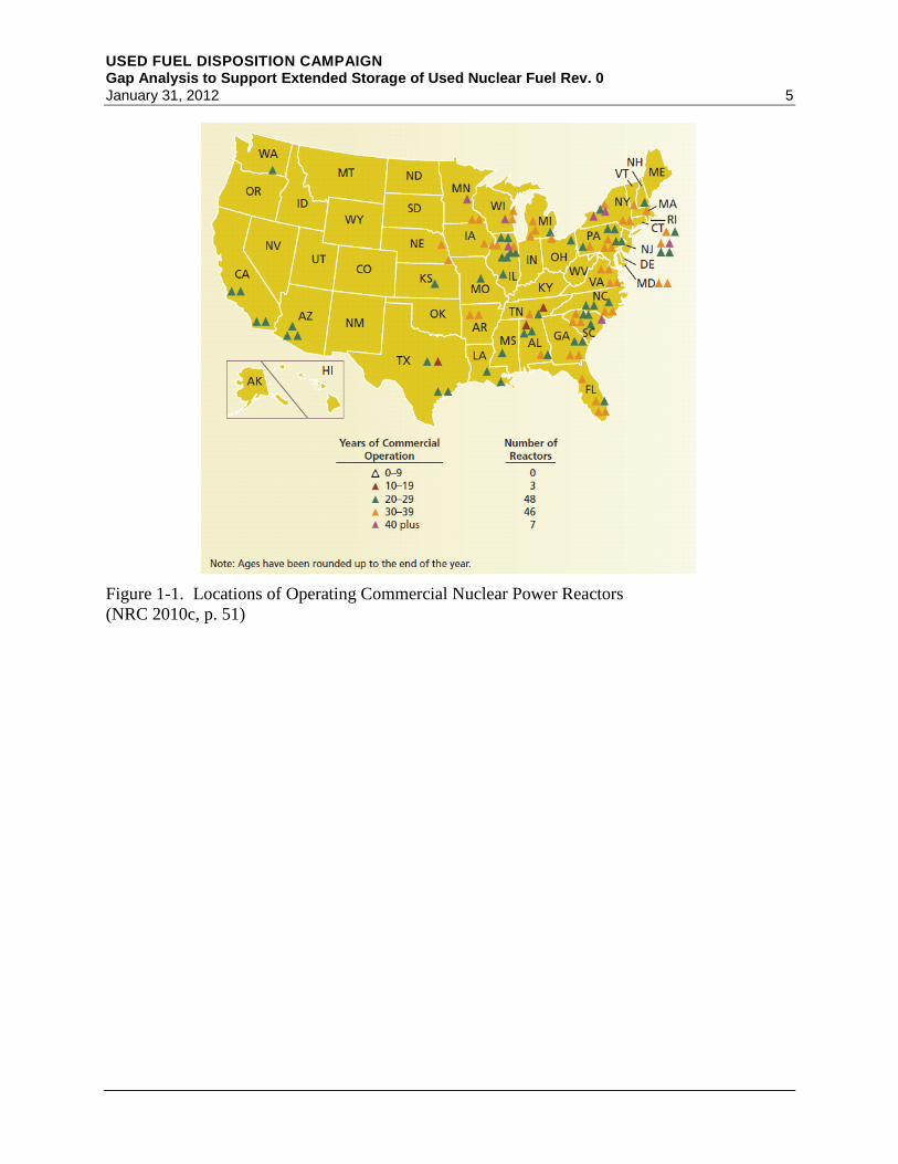
2-1. Sealed Storage Cask Demonstration at E-MAD at NTS ...................................................... 14
2-2. Sealed Storage Cask Thermocouple Instrumentation Locations .......................................... 14
2-3. Cutaway Diagram of the H.B. Robinson NUHOMS............................................................ 16
2-4. Location of Thermocouples in NUHOMS Tests at H.B. Robinson ..................................... 17
2-5. Dry Storage Casks at the Idaho National Laboratory INTEC Site ....................................... 18
2-6. Humboldt Bay Underground HI-STAR Independent Spent Fuel Storage Installation ........ 21
2-7. Transnuclear TN-68 Storage/Transport Cask. Schematic (left) and photo (right) .............. 24
2-8. NUHOMS Dry Storage Cask Being Loaded into the Horizontal Storage Module .............. 25
2-9. NUHOMS Dry Storage Casks Emplaced in Concrete Horizontal Storage Modules at
the Idaho National Laboratory Independent Spent Fuel Storage Installation ...................... 26
2-10. HI-STAR 100 Schematic of Overpack with MPC Partially Inserted (left) and Casks
in Storage (right) ................................................................................................................ 26
2-11. HI-STORM Cask ................................................................................................................ 27
2-12. NAC UMS Basket (left) and Loaded UMS Systems (right) .............................................. 28
2-13. NAC MAGNASTOR Basket Inserted in Canister (upper left); MAGNASTOR
Vertical Concrete Casks (VCCs) (upper right); Schematic of the MAGNASTOR
VCC (bottom) ..................................................................................................................... 29
4-1. Representative Minimum Cooling Times for PWR UNF as a Function of Burnup ............. 49
4-2. Illustration of Subcriticality Bases for Wet Loading and Retrieval Operations ................... 52
4-3. Illustration of Subcriticality Bases for Transportation ......................................................... 53
4-4. Illustration of Transportation Subcriticality Bases after a Period of Dry Storage ................ 55
4-5. CASTOR V/21 as It Is Transported at the Idaho National Laboratory ................................ 56
4-6. REA-2023 Cask as It Is Transported at the Idaho National Laboratory .............................. 57
5-1. Examples of Fuel Pellet Cracking in PWR Fuel with Burnup ~45 GWd/MTU .................. 75
5-2. Hydride Distribution and Morphology in Zry-4 Cladding from a High-Burnup Fuel
Rod Irradiated to 64 GWd/MTU in One of the H.B. Robinson Reactors ............................ 92
5-3. Hydride Distribution and Morphology of ZIRLOTM
Cladding from a High-Burnup
Fuel Rod Irradiated in the North Anna Reactors to 70 GWd/MTU: ................................... 93

USED FUEL DISPOSITION CAMPAIGN Gap Analysis to Support Extended Storage of Used Nuclear Fuel Rev. 0
January 31, 2012 xvii
5-4. Hydride Distribution and Morphology at ≈2960 mm Above Rod Bottom for M5®
Cladding from a High-Burnup Fuel Rod Irradiated in One of the Ringhals Reactors
to 63 GWd/MTU .................................................................................................................. 94
5-5. Post-Drying Radial-Hydride Formation in High-Burnup ZIRLOTM
Cladding (a) with
425-wppm H Subjected to 110-MPa Hoop Stress at 400°C, and (b) with 720-wppm
Subjected to 140-MPa Hoop Stress at 400°C ...................................................................... 95
5-6. Clad Oxidation from the Argonne National Laboratory Tests ........................................... 102
TABLES
S-1. Summary of Cross-Cutting Needs ........................................................................................ vii
S-2. Summary of High- and Medium-Priority Degradation Mechanisms That Could
Impact the Performance of Structures, Systems, and Components (SSCs) During
Extended Storage .................................................................................................................. ix
2-1. Used Nuclear Fuel Dry Storage Designs .............................................................................. 21
2-2. Used Nuclear Fuel Dry Storage Designs Approved for General Use by NRC .................... 22
4-1. Possible Technologies Sensitive to Medium- and High-Priority Degradation
Phenomena for the Fuel Cladding and Container ................................................................ 65
5-1. Degradation Mechanisms That Could Impact the Performance of the Fuel ........................ 80
5-2. Degradation Mechanisms That Could Impact the Performance of the Cladding ............... 107
5-3. Degradation Mechanisms That Could Impact the Performance of the Grid Spacers ......... 114
5-4. Degradation Mechanisms That Could Impact the Performance of Fuel Baskets ............... 119
5-5. Degradation Mechanisms That Could Impact the Performance of Neutron Poisons ......... 129
5-6. Degradation Mechanisms That Could Impact the Performance of Neutron Shields ......... 135
5-7. Degradation Mechanisms That Could Impact the Performance of the Container –
Welded Canister or Bolted Direct-Load Casks .................................................................. 148
5-8. Degradation Mechanisms That Could Impact the Performance of the Concrete
Overpack ............................................................................................................................ 161
6-1. Summary of Cross-Cutting Needs ...................................................................................... 166
6-2. Summary of High- and Medium-Priority Degradation Mechanisms That Could
Impact the Performance of Structures, Systems, and Components During Extended
Storage ............................................................................................................................... 169
A-1. Independent Spent Fuel Storage Installations in the United States by License Date ........ 191
B-1. Dry Cask Storage in the United States by Vendor ............................................................. 197

USED FUEL DISPOSITION CAMPAIGN Gap Analysis to Support Extended Storage of Used Nuclear Fuel Rev. 0
xviii January 31, 2012
ACRONYMS
ACI American Concrete Institute
ADI acoustic daylight imaging
AET acoustic emission testing
ALARA as low as is reasonably achievable
AMP Aging Management Plan or Program
ANL Argonne National Laboratory
ANS American Nuclear Society
ANSI American National Standards Institute
ASME American Society of Mechanical Engineers
ASTM American Society for Testing and Materials
BAM Bundesanstalt für Materialforschung und –prüfung, the German Federal Institute
for Materials Research and Testing
BRC Blue Ribbon Commission on America’s Nuclear Future
BSC Bechtel SAIC Co. LLC
BWR boiling water reactor
CANDU Canada Deuterium Uranium
CFR Code of Federal Regulations
CoC Certificate of Compliance
CRIEPI Central Research Institute of Electric Power Industry, a research institute of the
Japanese nuclear industry
crud A colloquial term for corrosion and wear products (rust particles, etc.) that
become radioactive (i.e., activated) when exposed to radiation.
CWSRA cold-work stress relief annealed
DCSCP Dry Cask Storage Characterization Project
DCSS dry cask storage system
DHC delayed hydride cracking
DOE U.S. Department of Energy
DPC dual-purpose canister/cask
DSC dry shielded canister
E-MAD Engine Maintenance, Assembly and Disassembly
EPRI Electric Power Research Institute
ESCP Extended Storage Collaboration Program
ET eddy current testing
GTCC greater than Class C
GUT guided wave testing
GWd gigawatt-day
GWe gigawatt electric

USED FUEL DISPOSITION CAMPAIGN Gap Analysis to Support Extended Storage of Used Nuclear Fuel Rev. 0
January 31, 2012 xix
HBS high burnup structure
HI-STAR Holtec International Storage, Transport, and Repository
HLW high-level waste
HSM horizontal storage module
IAEA International Atomic Energy Agency
INEEL Idaho National Engineering and Environmental Laboratory
INEL Idaho National Engineering Laboratory
INL Idaho National Laboratory
INTEC Idaho Nuclear Technology and Engineering Center
ISFSI independent spent fuel storage installation
ISG interim staff guidance
ITS important to safety
LANL Los Alamos National Laboratory
LLNL Lawrence Livermore National Laboratory
LWR light water reactor
MAGNASTOR Modular, Advanced Generation, Nuclear All-purpose Storage
MeV mega electron volt(s)
mm millimeter(s)
MOX mixed oxide
MPa megapascal
MPC multipurpose canister/cask
mSv milli Sievert
MTU metric tons (Tonnes) of uranium
N/A not applicable
NAC NAC International, Inc.
NAS National Academy of Sciences
NEI Nuclear Energy Institute
NEUP Nuclear Energy University Program
NEWS nonlinear elastic wave spectroscopy
NRC U.S. Nuclear Regulatory Commission
NTS Nevada Test Site
NUHOMS Nutech horizontal modular storage
NUREG publication prepared by staff of the U.S. Nuclear Regulatory Commission
NUREG/CR technical report prepared by a contractor to the U.S. Nuclear Regulatory
Commission
NWPA Nuclear Waste Policy Act
NWTRB U.S. Nuclear Waste Technical Review Board
PCI pellet–clad interaction
PCMI pellet–clad mechanical interaction
PFS Private Fuel Storage LLC

USED FUEL DISPOSITION CAMPAIGN Gap Analysis to Support Extended Storage of Used Nuclear Fuel Rev. 0
xx January 31, 2012
PNL Pacific Northwest Laboratory
PNNL Pacific Northwest National Laboratory
ppm part(s) per million
pRXA partially recrystallized annealed
psig pounds per square inch gauge
PWR pressurized water reactor
R&D research and development
RBMK reaktor bolshoy moschnosti kanalniy
rem unit of dose: roentgen equivalent man: 1 rem = 0.01 Sv
RI resonance ultrasound inspection
RT room temperature
RXA recrystallized annealed
SAR safety analysis report
SCC stress corrosion cracking
SFST Spent Fuel Storage and Transportation (a division of the NRC)
SNF spent nuclear fuel
SNL Sandia National Laboratories
SRA stress relief annealed
SRNL Savannah River National Laboratory
SSC structure, system, and component
SPP second-phase precipitate
SRA stress relieved annealed
Sv sievert, unit of dose
TAN Test Area North
TMI Three Mile Island
TN Transnuclear, Inc.
UFDC Used Fuel Disposition Campaign
UMS Universal MPC System
UNF used nuclear fuel
U.S. United States (adjective)
VSC ventilated storage cask
wppm weight parts per million
wt% weight percent
YMP Yucca Mountain Project
Zircaloy zirconium alloy
Zr zirconium
Zry-2 Zircaloy-2
Zry-4 Zircaloy-4

USED FUEL DISPOSITION CAMPAIGN Gap Analysis to Support Extended Storage of Used Nuclear Fuel Rev. 0 January 31, 2012 1
USED FUEL DISPOSITION CAMPAIGN Gap Analysis to Support Extended Storage
of Used Nuclear Fuel
1. INTRODUCTION
The U.S. Department of Energy Office of Nuclear Energy (DOE-NE), Office of Fuel Cycle
Technology has established the Used Fuel Disposition Campaign (UFDC) to conduct the
research and development (R&D) activities related to storage, transportation, and disposal of
used nuclear fuel (UNF) and high-level radioactive waste (HLW). The mission of the UFDC is
To identify alternatives and conduct scientific research and technology
development to enable storage, transportation and disposal of used nuclear fuel
and wastes generated by existing and future nuclear fuel cycles.
The recent decision by DOE to no longer fund the development of a geologic repository at Yucca
Mountain, Nevada, for the disposal of spent nuclear fuel (SNF)a necessitates storage of UNF
until a disposition pathway is available. At the direction of the President, the Secretary of
Energy established the Blue Ribbon Commission (BRC) on America’s Nuclear Future to conduct
a comprehensive review of policies for managing the back end of the nuclear fuel cycle,
including all alternatives for the storage, processing, and disposal of civilian and defense UNF,
HLW, and materials derived from nuclear activities. The BRC is to provide advice, evaluate
alternatives, and make recommendations to the Secretary by January 2012.
Within the UFDC, the Storage and Transportation task has been created to address issues of
extended or long-term storage and transportation. The near-term objectives of the Storage and
Transportation task are to use a science-based approach to
Develop the technical bases to support the continued safe and secure storage of UNF for
extended periods.
Develop the technical bases for retrieval of UNF after extended storage.
Develop the technical bases for transport of high burnup fuel; as well as low and high burnup
fuel after dry storage.
Together, these objectives will help formulate the technical bases to support licensing for
extended storage of UNF that will accommodate all disposition options. It is not sufficient for
UNF to simply maintain its integrity during the storage period, it must maintain it in such a way
that it can withstand the physical forces of handling and transportation associated with restaging
a Nuclear fuel discharged from a transmutation system (i.e., reactor or accelerator-driven system) is termed as “used nuclear fuel”
until it is determined that the fuel has no subsequent value and will be disposed of in a geologic repository. At this point, the fuel
is termed as “spent nuclear fuel.” As storage and transportation are currently required no matter the ultimate disposition pathway
chosen, the terminology “used nuclear fuel” or UNF is used throughout this document, except SNF is used when it is part of
historical terminology (e.g., spent fuel pool).

USED FUEL DISPOSITION CAMPAIGN Gap Analysis to Support Extended Storage of Used Nuclear Fuel Rev. 0
2 January 31, 2012
the fuel and moving it to a treatment/recycling facility or geologic repository. While both wet
and dry storage have been shown to be safe options for storing UNF, the program will focus on
dry storage at reactor or centralized locations with storage times exceeding the currently longest
licensed dry storage period. Although the initial emphasis of the program will be on commercial
light-water reactor (LWR) uranium-oxide fuel, DOE-owned research and defense used nuclear
fuels, as well as alternative and advanced fuel concepts being investigated by DOE, will be
addressed later in this program. Because limited information is available on the properties of
high burnup fuel (exceeding 45 gigawatt-days per metric tonne of uranium [GWd/MTU]), and
because much of the fuel currently discharged from today’s reactors exceeds this burnup
threshold, a particular emphasis of this program will be focused on high burnup fuels.
1.1 Background
When fuel is no longer capable of efficiently sustaining a chain reaction, it is removed from the
reactor and is termed UNF or SNF. Because of the high heat load and radioactivity, UNF is
initially stored in water-filled pools to provide both cooling and shielding. Reactors were not
designed or built to store all of the UNF produced over their lifetime of operation. This is
especially true for reactors applying for license extensions of up to 20 years, bringing their total
operating lifetime to 60 years. Most reactors initially addressed this storage shortfall by
reracking their pools to increase the in-pool storage capability by decreasing the spacing between
assemblies. Typically this also requires the use of additional fixed neutron poisons and burnup
credit to provide the required reactivity margin to demonstrate subcriticality. As the pools reach
capacity, it is necessary to remove assemblies to ensure that the pool retains sufficient space to
support refueling operations. Without an operating repository, centralized storage facility, or
reprocessing facility, the only option is to build additional onsite storage, either wet or dry.
Because dry storage systems are designed to allow passive cooling, their overall cost and
maintenance are expected to be less than the cost and maintenance for an additional pool. The
commercial nuclear industry has been actively pursuing dry storage to meet its fuel storage
needs.
1.1.1 Dry Storage History and Regulation
In November 1980, the U.S. Nuclear Regulatory Commission (NRC) issued U.S. Code of
Federal Regulations Title 10, Part 72 (10 CFR 72), Licensing Requirements for the Independent
Storage of Spent Fuel and High-Level Radioactive Waste. Under this regulation, an applicant
could apply for a site-specific license to place fuel in wet or dry storage in an independent spent
fuel storage installation (ISFSI). In 1982, the Nuclear Waste Policy Act (NWPA) was passed by
Congress and enacted January 7, 1983. Under Section 218 of the NWPA, the Secretary of
Energy was directed to “…establish a demonstration program, in cooperation with the private
sector, for the dry storage of spent nuclear fuel at civilian nuclear power reactor sites…” (NWPA
§218(a)) This collaboration was to include “…the establishment of a research and development
program for the dry storage of not more than 300 metric tons of spent nuclear fuel at facilities
owned by the Federal Government… The purpose of such program shall be to collect necessary
data to assist the utilities in the licensing process” (NWPA §218(c)(2)).

USED FUEL DISPOSITION CAMPAIGN Gap Analysis to Support Extended Storage of Used Nuclear Fuel Rev. 0 January 31, 2012 3
DOE, together with the Electric Power Research Institute (EPRI), entered into an agreement with
Virginia Power (now Dominion Generation) to demonstrate a number of dry storage casks (see
Section 2.1.4 for details) at the Idaho National Engineering Laboratory (INEL, now Idaho
National Laboratory, INL). The main purpose of this demonstration was to gain experience in
loading the various casks and to obtain temperature data to validate thermal models and dose
measurements to ensure the shielding functioned as modeled. This research is documented in a
series of reports by EPRI and Pacific Northwest Laboratory (PNL, now Pacific Northwest
National Laboratory, PNNL), and the NRC.
Upon receiving a site-specific license in July 1986, Virginia Power then loaded three different
casks at its Surry plant to store at its ISFSI. DOE continued in cooperative agreements with two
other utilities to demonstrate additional dry storage technologies. These demonstrations
facilitated other licenses, such as at the H.B. Robinson station in August 1986 for the Nutech
horizontal modular storage (NUHOMS) concrete storage system. In 1990, 10 CFR 72 was
revised to allow for dry storage under the general license that an operating reactor holds under
10 CFR 50.
The initial licenses granted under 10 CFR 72.42(a) were limited to up to 20 years, and renewals
could also be for up to 20 years. Thus, the license at Surry was set to expire in 2006. As part of
the license renewal process, the NRC sought data to support the technical basis for extended
storage. This included assurance that there was no significant degradation of the fuel or dry cask
storage system (DCSS) that would prevent the various systems, structures, and components
(SSCs) from continuing to meet the required safety functions (see Section 2.4 for additional
details). The CASTOR V/21 cask that was part of the initial demonstration at INL had been
loaded with fuel from the Surry plant and thus was an applicable analogue for the CASTOR
V/21 cask at Surry. A jointly funded project between NRC, EPRI, and DOE was initiated in
1999 to open the cask at INL (then the Idaho National Engineering and Environmental
Laboratory, INEEL). The project was to obtain data on material performance of the DCSS and
SNF.
As documented in the final project technical report (EPRI 2002a), the conclusions were that
there was no evidence of significant degradation of the important to safety (ITS) SSCs, no
evidence of fuel rod failure, maximum fuel cladding creep of no more than 0.1%, no evidence
for hydride reorientation, and little if any cladding annealing had occurred during the 14 years in
dry storage. In fact, it is often stated that the cask interior and fuel appeared the same as when
they were loaded. Based on these results, the NRC not only granted the extension for the Surry
ISFSI for the additional 20 years as in the regulation but also granted a 40-year extension
(NRC 2005a) under the exemption process. Subsequently, two other sites, H.B. Robinson
(NRC 2005b) and Oconee (NRC 2009a) have been granted 40-year license extensions for their
ISFSIs.
Several aspects of the CASTOR V/21 demonstration at INL could limit its applicability to the
full range of UNF requiring storage. First, the cask was loaded dry and never had any water in it.
Thus, there was no possibility for any of the degradation mechanisms that require water to have
occurred. This lack of water is not prototypic of casks that are loaded at a reactor site in the pool
and then vacuum dried. Second, while the fuel and DCSS did experience large temperature
USED FUEL DISPOSITION CAMPAIGN Gap Analysis to Support Extended Storage of Used Nuclear Fuel Rev. 0
4 January 31, 2012
swings during the thermal testing, it was not necessarily prototypic of the temperatures that occur
during vacuum drying. Third, there was very limited pre-characterization of the fuel; thus the
conclusions for cladding creep and other mechanisms had to be drawn by comparing this fuel to
a similar fuel, thereby introducing some uncertainty. Finally, and most important, the assembly-
average burnup of the Surry fuel was 35.7 GWd/MTU (EPRI 2002a). Given this is the only data
point that the NRC has for behavior of fuel after years in dry storage, this is one reason why the
NRC differentiates between low (≤45 GWd/MTU) and high burnup (>45 GWd/MTU) fuels.
Finally, effective May 17, 2011, 10 CFR 72.42(a) was officially changed to allow an initial
license period of up to 40 years and license extensions of up to 40 years. This is combined with
the NRC Waste Confidence Rule (10 CFR 51.23) that states that the Commission has confidence
that fuel can be stored safely (wet or dry) for at least 60 years beyond the licensed life of the
reactor without significant environmental effects. For a reactor that had an initial operating
license of 40 years and was granted a 20-year extension, this means the NRC has confidence that
fuel can be stored for a total of up to 120 years. In addition, for its Generic Environmental
Impact Statement to support the Waste Confidence Rule, the NRC is analyzing behavior up to
300 years. However, this rulemaking does not grant approval for longer licenses than currently
allowed by 10 CFR 72.42(a). Additional direction to the NRC staff is found in SECY-11-0029
(NRC 2011a).
1.1.2 Current Status
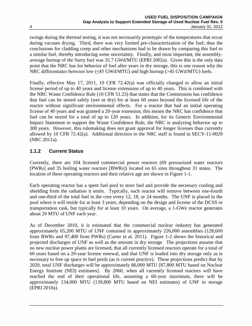
Currently, there are 104 licensed commercial power reactors (69 pressurized water reactors
[PWRs] and 35 boiling water reactors [BWRs]) located on 65 sites throughout 31 states. The
location of these operating reactors and their relative age are shown in Figure 1-1.
Each operating reactor has a spent fuel pool to store fuel and provide the necessary cooling and
shielding from the radiation it emits. Typically, each reactor will remove between one-fourth
and one-third of the total fuel in the core every 12, 18, or 24 months. The UNF is placed in the
pool where it will reside for at least 3 years, depending on the design and license of the DCSS or
transportation cask, but typically for at least 10 years. On average, a 1-GWe reactor generates
about 20 MTU of UNF each year.
As of December 2010, it is estimated that the commercial nuclear industry has generated
approximately 65,200 MTU of UNF contained in approximately 226,000 assemblies (128,600
from BWRs and 97,400 from PWRs) (Carter et al. 2011). Figure 1-2 shows the historical and
projected discharges of UNF as well as the amount in dry storage. The projections assume that
no new nuclear power plants are licensed, that all currently licensed reactors operate for a total of
60 years based on a 20-year license renewal, and that UNF is loaded into dry storage only as is
necessary to free up space in fuel pools (as is current practice). These projections predict that by
2020, total UNF discharges will be approximately 86,000 MTU [87,800 MTU based on Nuclear
Energy Institute (NEI) estimates]. By 2060, when all currently licensed reactors will have
reached the end of their operational life, assuming a 60-year maximum, there will be
approximately 134,000 MTU (139,800 MTU based on NEI estimates) of UNF in storage
(EPRI 2010a).
USED FUEL DISPOSITION CAMPAIGN Gap Analysis to Support Extended Storage of Used Nuclear Fuel Rev. 0 January 31, 2012 5
Figure 1-1. Locations of Operating Commercial Nuclear Power Reactors
(NRC 2010c, p. 51)

USED FUEL DISPOSITION CAMPAIGN Gap Analysis to Support Extended Storage of Used Nuclear Fuel Rev. 0
6 January 31, 2012
Figure 1-2. Historical and Projected Discharges of Used Nuclear Fuel, 1986–2020
(EPRI 2010a, p. 1-3, Figure 1-2; reprinted with permission)
When spent fuel pools get close to capacity, the industry has been turning to dry storage as an
alternative. Since the first dry storage facility was licensed by the NRC in 1986, a total of 63 (as
of November 2010, including 48 general licenses granted under 10 CFR 72) licenses for ISFSIs
have been granted for commercial power plants and three additional licenses granted at DOE
facilities (two at INL and one at Fort St. Vrain). One of the commercial licenses is for the
private fuel storage centralized ISFSI in Utah that has not begun construction because of ongoing
litigation. A detailed listing of the ISFSIs, the year licensed, and the storage technology used is
provided in Appendix A. Figure 1-3 shows the location of the ISFSIs spread across 33 states.
The NEI predicts that by 2020, an additional 34 reactors will require dry storage capability
(NEI 2011). It is estimated that by 2026, all but 3 of the currently operating commercial nuclear
power plants will require dry storage for their UNF.
0
10000
20000
30000
40000
50000
60000
70000
80000
90000
100000
1986 1988 1990 1992 1994 1996 1998 2000 2002 2004 2006 2008 2010 2012 2014 2016 2018 2020
Cu
mu
lati
ve
MT
U D
isc
ha
rge
d
Dry Storage Cumulative Total Inventory

USED FUEL DISPOSITION CAMPAIGN Gap Analysis to Support Extended Storage of Used Nuclear Fuel Rev. 0 January 31, 2012 7
Figure 1-3. Locations of Independent Spent Fuel Storage Installations
(Source: http://www.nrc.gov/waste/spent-fuel-storage/locations.pdf)
1.1.3 ISFSI Only Storage Sites
When a utility shuts down or decommissions a commercial nuclear power plant, it is still
responsible for the storage of the UNF. Because there is no central storage location or repository
available, this fuel remains onsite, even after all of the infrastructure associated with the reactor
and its operation is removed. Utilities are required to maintain active security and monitoring at
these sites, creating a large expense with no income. Most utilities have removal of the UNF
from these sites with no operating reactor as one of their top priorities. An additional issue can
arise when not only is the reactor shut down but the spent fuel pool is decommissioned, thus
limiting the ability to mitigate potential problems with the DCSS. The NRC refers to sites where
the 10 CFR 50 license for the reactor has been terminated, which can occur only when all
facilities including the spent fuel pool have been decommissioned, but fuel still remains in
storage as “ISFSI Only.”
There are 15 commercial light water power reactors that have been permanently shut down
(NEI 2011), not including the Shoreham reactor that only completed low-power testing and has
been fully decommissioned, with the fuel shipped to another utility. Three other non-light water
commercial reactors also have been permanently shut down. Another 10 reactors, either
commercially owned but not considered power reactors or DOE-owned power reactors, also
have been permanently shut down. Of the commercial LWR sites that have been shut down,

USED FUEL DISPOSITION CAMPAIGN Gap Analysis to Support Extended Storage of Used Nuclear Fuel Rev. 0
8 January 31, 2012
6 (Big Rock Point, Connecticut Yankee (Haddam Neck), Maine Yankee, Rancho Seco, Trojan,
and Yankee Rowe) are currently classified as “ISFSI Only” (NRC 2011b). Humboldt Bay is
effectively in that category as well because the pool has been decommissioned, but the license
for the reactor is expected to be terminated in 2015. LaCrosse is expected to transfer all of its
fuel to dry storage in 2011 and then decommission its spent fuel pool. The two units at Zion are
expected to do the same within the next 3 years.
From the information included in Figure 1-1, it is clear that if the current fleet of operating
reactors has their licenses extended by 20 years to allow for 60-year total lifetime operation, then
an additional seven reactors will move toward “ISFSI Only” by 2030. Shortly after 2040, half of
the current fleet will become “ISFSI Only” sites as the reactors and supporting infrastructure are
decommissioned. All but 3 of the current 104 reactors will have their extended licenses expire
within the next 40 years. Thus, one of the main drivers for this program is to determine if all
UNF stored at these sites for extended periods can be transported for ultimate disposition,
preferably without the need to repackage at the ISFSI.
1.1.4 High Burnup Issue
As the burnup of fuel increases, a number of changes occur that may affect the performance of
the fuel, cladding, and assembly hardware in storage and transportation. These changes include
increased cladding corrosion layer thickness, increased cladding hydrogen content, increased
cladding creep strains, increased fission gas release, and the formation of the high burnup
structure (HBS) at the surface of the fuel pellets. Sections 5.1 and 5.2 discuss in more detail
these changes and their possible impact on the condition of the fuel during storage and
transportation. The current maximum rod-averaged burnup is limited by NRC to 62 GWd/MTU
because of these changes and the lack of data at higher burnups, especially under design basis
accident conditions. Newer cladding materials such as ZIRLO™ and M5® were developed to
help reduce these high burnup effects. However, because these materials are relatively new,
there is very limited publicly available data to determine how these materials may perform under
storage and transportation conditions.
The Dry Cask Storage Characterization Project (DCSCP) (EPRI 2002a) demonstrated the
performance of the DCSS and low-burnup UNF after 14 years in storage. As discussed in
Section 1.1.1, the positive results of this demonstration allowed NRC to extend the license
periods for low burnup fuel, which is defined as ≤ 45 GWd/MTU. While NRC does allow high
burnup fuel in properly designed and licensed storage casks, there is no similar data to verify
performance during dry storage. Because these original licenses were granted based on the
ability of the entire system, including the fuel, to meet all safety functions, it is possible that data
for high burnup UNF will be needed to facilitate license extensions. Similarly, high burnup fuel
is allowed by NRC regulations to be transported only on a case-by-case basis until additional
data on its performance are obtained.
Figure 1-4 shows the discharge burnup trend for both PWRs and BWRs. The average discharge
burnup for PWRs is currently approximately 48 GWd/MTU, and for BWRs it is approximately
43 GWd/MTU (EPRI 2010a). By 2020 it is projected that the maximum discharge burnups will
be 58 GWd/MTU and 48 GWd/MTU for PWRs and BWRs, respectively. One of the main

USED FUEL DISPOSITION CAMPAIGN Gap Analysis to Support Extended Storage of Used Nuclear Fuel Rev. 0 January 31, 2012 9
focuses of this program will be to obtain the data on high burnup fuel and the newer cladding
materials and how the storage and transportation systems perform to address the growing
inventory of high burnup fuel.
Figure 1-4. Historical and Projected Average PWR and BWR Discharge Burnups
(EPRI 2010a, p. 2-3, Figure 2-1; reprinted with permission)
As noted in Section 1.1.3, the Maine Yankee PWR has been completely decommissioned and is
defined as “ISFSI Only,” meaning there is no spent fuel pool or supporting reactor infrastructure
on site. This is important, as Maine Yankee was only shut down on December 6, 1996, and thus
produced some high burnup fuel. Maine Yankee has 1434 assemblies in 60 NAC International,
Inc. (NAC) Universal MPC System (UMS) casks (see Section 2.2.3). The NAC UMS was
issued its Certificate of Compliance (CoC) on November 20, 2000, which means that it expires
on November 20, 2020 (EPRI 2010b). Maine Yankee will be the first utility to apply for a dry
storage license extension that will include high burnup fuel.
1.1.5 Dry Storage and Transportation Systems Issues
Dry storage systems include the necessary SSCs to facilitate loading, maintain an inert
environment, ensure eventual retrieval, and, for dual-purpose systems, enable transportation of
used nuclear fuel. Dry storage systems include the following SSCs:
0
10
20
30
40
50
60
70
1999 2003 2007 2011 2015 2019 2023 2027 2031 2035 2039 2043 2047 2051 2055
Av
era
ge
Dis
ch
arg
e B
urn
up
MW
d/M
TU
)
Avg. PWR Avg. BWR

USED FUEL DISPOSITION CAMPAIGN Gap Analysis to Support Extended Storage of Used Nuclear Fuel Rev. 0
10 January 31, 2012
a concrete or metal overpack that provides protection for a welded or bolted confinement
barrier from environmental conditions and natural phenomena – The overpack also provides
radiation shielding.
a welded or bolted confinement barrier that prevents release of radioactive material and
maintains an inert atmosphere
fuel baskets, including fixed neutron poisons, that hold the fuel assemblies in a set geometry
to facilitate loading and retrieval of used nuclear fuel, transfer heat, and maintain
subcriticality.
Dry storage systems were originally licensed for a 20-year period. Although three ISFSIs and
associated dry storage systems were granted license extensions for an additional 40 years, other
ISFSIs and storage systems may not receive similar extensions. Many site-specific factors
including environmental conditions (e.g., marine environments) and natural phenomena (e.g.,
seismicity) could impact the performance of the dry storage systems such that extensions may be
more limited. With extended dry storage beyond 60 years, demonstrating continued efficacy of
the various SSCs of dry storage systems becomes challenging.
Most of the storage systems were designed to serve a dual purpose of storage and transportation.
However, transportation of these systems after a period of storage is required to be licensed
separately to demonstrate compliance with applicable transportation safety requirements. To
meet transportation confinement and subcriticality requirements, the used nuclear fuel, fuel
baskets, neutron poisons, and the confinement barrier for transportable storage casks must
remain intact during normal conditions of transport and hypothetical accident conditions.
Although alternate transportation approaches and safety bases may be pursued to demonstrate
subcriticality, such as moderator exclusion, there are regulatory and technical hurdles that must
be overcome before they can be adopted.
The evaluation documented in this report focuses on both determining the conditions that lead to
failure of dry storage SSCs as well as the material and structural properties of these SSCs as a
function of storage conditions. This includes analysis of their response to mechanical loads
associated with storage design basis accidents and transportation hypothetical accident
conditions. Sections 5.1 through 5.9 discuss in more detail the impact of extended storage on the
various SSCs of dry storage systems and their ability to meet applicable storage and
transportation requirements.
1.2 Scope
The Storage and Transportation task within the UFDC is tasked with developing the technical
bases to support extended storage and transportation of UNF, as well as HLW and other wastes
that may be generated through advanced fuel cycles. There is a pressing need to obtain data
within the next decade to support relicensing efforts, especially for high burnup LWR fuels and
newer cladding types and how they impact the entire DCSS. Thus, the initial focus of the
program is on commercial UNF. Similarly, until a disposition pathway, e.g., recycling or
geologic disposal, is chosen and implemented for UNF, the storage periods will likely be longer

USED FUEL DISPOSITION CAMPAIGN Gap Analysis to Support Extended Storage of Used Nuclear Fuel Rev. 0 January 31, 2012 11
than were originally intended. The ability of the ITS SSCs to continue to meet safety functions
over extended times must be determined. In addition, it needs to be determined if these SSCs
can also meet safety functions when the UNF is transported to its final location. To facilitate all
options for disposition and to maintain retrievability and normal back-end operations, it is
considered an important objective of this program to demonstrate that the UNF remains intact
after extended storage. Other options, such as canning of all UNF, which involves sealing one or
more assemblies in a metal “box” or “can,” are available and must be analyzed from a total
systems perspective to determine overall benefit to the program.
This report documents the initial gap analysis performed to identify data and modeling needs to
develop the desired technical bases. The methodology followed is described in Section 3.
Results of the literature review for each ITS SSC and the potential degradation mechanisms are
presented in Sections 4 and 5. In almost all cases, additional data are required, often because
there is limited data on the new materials used in more modern fuels or DCSS or because the
effects of high burnup and extended storage are not fully known. Based on the criteria outlined
in Section 3.3.1, the importance of obtaining this data is ranked as High, Medium, or Low. The
UFDC will use a science-based approach combining theory, experimental work, and advanced
modeling and simulation to close the data gaps and develop the technical bases for extended
storage and transportation of UNF. Only brief descriptions of how to fill the data gaps are
provided in this report. A future report will document the details of proposed testing and
modeling and assess their priorities based on a set of criteria aimed at closing the identified gaps.
The future report will document how the collected data can be integrated in a system
performance model to evaluate and demonstrate continued safety of extended storage of used
nuclear fuel. In addition to specific testing and modeling plans and associated priorities, the
report will also include the necessary quality assurance requirements and implementation plans.
In fiscal year 2012, testing and modeling of the gaps identified as High priority will begin,
including continuing the cladding ring compression tests at ANL and initiating testing to
establish the link between unirradiated and irradiated cladding.
The degradation mechanisms identified in this report are limited to those during normal
operations and potential off-normal conditions. Impacts of degradation mechanisms on
demonstrating compliance with design basis accidents including those initiated by natural
phenomena are not discussed in this report. This report is meant to be a living document that
will be updated as additional technical data become available and as policy decisions are
implemented. Future revisions will include formulating the technical bases for consideration of
accidents and natural phenomena during long-term storage. In addition, future revisions will
compare the gap analysis generated as part of the UFDC program with similar ones developed by
the U.S. Nuclear Waste Technical Review Board (NWTRB), the NRC, EPRI, and international
organizations. A similar gap analysis effort is under way as part of the UFDC to examine the
needs to meet transportation requirements. Once the transportation gaps have been analyzed, the
results will be consolidated in a consistent manner in a revision to this report to form a single set
of gaps and congruous direction for addressing these gaps to meet applicable storage and
transportation requirements.

USED FUEL DISPOSITION CAMPAIGN Gap Analysis to Support Extended Storage of Used Nuclear Fuel Rev. 0
12 January 31, 2012

USED FUEL DISPOSITION CAMPAIGN Gap Analysis to Support Extended Storage of Used Nuclear Fuel Rev. 0 January 31, 2012 13
2. DRY STORAGE
The need for dry storage of UNF has grown rapidly since the NRC first developed the regulatory
framework for storage of UNF outside of the reactor fuel pools. This section will first review the
various dry storage demonstration projects used to obtain the data to support the initial licensing
and license extensions of low burnup fuel dry storage. Next, a brief description of various dry
cask storage technologies will be presented. Finally, a summary of the regulations and guidance
governing dry storage is given.
2.1 Dry Cask Storage Demonstration Projects
2.1.1 Nevada Test Site
The purpose of the Spent Fuel Handling and Packaging Program Demonstration at the Nevada
Test Site (NTS, now Nevada National Security Site) was to develop the capability to encapsulate
typical commercial spent fuel assemblies in a canister and establish, by testing, the suitability of
one or more surface or near-surface concepts for interim dry storage of spent fuel assemblies.
Early thermal testing of spent or used fuel in dry cask storage to develop thermal models
occurred at the Engine Maintenance, Assembly, and Disassembly facility (E-MAD) at NTS in
1978 with a spent fuel sealed storage cask test (Westinghouse 1980). A PWR spent fuel
assembly was sealed in a stainless steel canister in the E-MAD hot cell, which was then placed in
a carbon steel liner and then in a reinforced concrete shielded cask as shown in Figure 2-1. The
sealed storage cask was then placed on a concrete pad adjacent to the E-MAD. The PWR
assembly selected was characteristic of 25-GWd/MTU fuel assemblies approximately 3 years out
of the reactor with a 1.25-kW thermal power.
Thermocouple instrumentation was placed on the outside of the canister, the outside of the steel
liner, and embedded within the concrete of the sealed storage cask. The instrumentation
locations, excluding those embedded in the concrete, are shown in Figure 2-2.
A thermal model of the sealed storage cask was developed, and good agreement was obtained
between the analyses and the test data for transient and steady-state conditions (Westinghouse
1980). Because the material properties that affect material degradation and material lifetimes
can be dependent upon temperature, thermal modeling continues to be essential for extended dry
storage. This early demonstration was instrumental in regulatory and industry acceptance of dry
storage.
2.1.2 Surry Power Station
With the passage of the NWPA in 1982, DOE was directed to enter into demonstration programs
of spent fuel storage systems at commercial nuclear reactor sites (NWPA §218 (a)). Virginia
Power entered into a cooperative agreement with DOE and EPRI in March 1984. As part of that
agreement, Virginia Power agreed to select and purchase casks to be tested at the federal site
(INEL at the time), select and ship spent fuel assemblies to the federal site, and design, license,
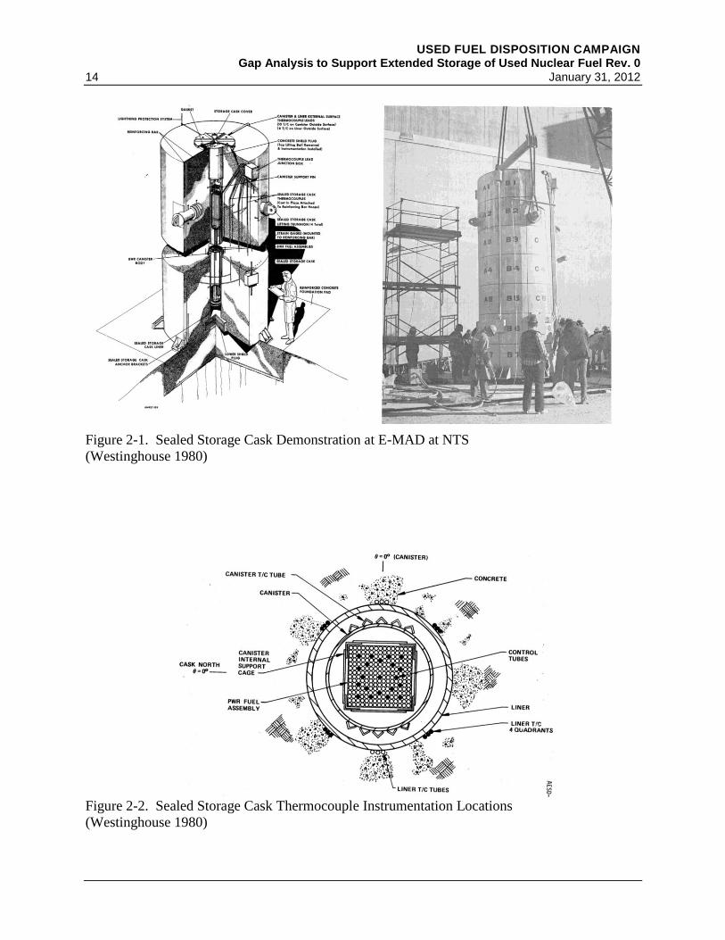
USED FUEL DISPOSITION CAMPAIGN Gap Analysis to Support Extended Storage of Used Nuclear Fuel Rev. 0
14 January 31, 2012
Figure 2-1. Sealed Storage Cask Demonstration at E-MAD at NTS
(Westinghouse 1980)
Figure 2-2. Sealed Storage Cask Thermocouple Instrumentation Locations
(Westinghouse 1980)

USED FUEL DISPOSITION CAMPAIGN Gap Analysis to Support Extended Storage of Used Nuclear Fuel Rev. 0 January 31, 2012 15
and operate a dry cask ISFSI at the Surry Power Station. Virginia Power submitted a site-
specific license application to the NRC in October 1982. The original 20-year license was
granted by the NRC in July 1986, making Virginia Power the first utility to obtain approval from
the NRC for aboveground storage of UNF in dry casks.
Virginia Power initially purchased nine CASTOR V/21 casks from General Nuclear Systems,
Inc., one of which was sent to INEL in December 1984 for use under the cooperative agreement.
The first cask was loaded at Surry in October 1986 with 21 PWR assemblies. The main purpose
of this initial demonstration was to obtain experience and develop comprehensive procedures for
this operation. A number of issues were identified (EPRI 1989) and corrected prior to loading
the next two casks in May and June 1987. As part of the cooperative agreement, more than one
cask type was to be demonstrated at the Surry ISFSI. Under site-specific licenses, the MC-10,
NAC-I28, CASTOR X/33, and TN-32 casks were successfully loaded and are currently stored at
the Surry ISFSI (NUREG-1350; NRC 2010c, Volume 22, Appendix I) (see Appendix B).
2.1.3 H.B. Robinson Nuclear Plant
In March 1984, DOE entered into a cooperative agreement with Carolina Power and Light Co.
(now Progress Energy). This agreement was to demonstrate the NUHOMS horizontal concrete
module design at an ISFSI. The test originally consisted of three concrete modules that each
could house 7 PWR fuel assemblies for a total of 21 assemblies. Five additional modules were
added to bring the total to 56 assemblies. Figure 2-3 shows a cutaway diagram of the original
NUHOMS module at H.B. Robinson. Additional details of NUHOMS systems are found in
Section 2.2.1.
Initial tests were performed in 1988–1989 using electrical heaters and an instrumented dry
shielded canister (DSC) and horizontal storage module (HSM). The first tests were conducted
with the heaters in the DSC placed in the transfer cask to evaluate thermal performance during
loading, vacuum drying, and backfilling with helium. The next set of tests had the DSC in the
HSM. The tests simulated both normal and blocked air flow. Seventy-six thermocouples were
used in the electric heater and in the later fuel tests, as shown in Figure 2-4, with thermocouples
measuring ambient, outlet air, canister, heat shield, and concrete temperatures. Two canisters
were instrumented with thermocouples, both on the outer shell of the canister, end caps, and the
center guide tubes of five of the stored fuel assemblies. The thermocouple leads were routed out
of the canister through a fitting to maintain canister integrity.
After the tests with the electric heaters were complete, the HSMs were loaded with UNF and the
peak basket, heat shield, concrete, and ambient temperatures were measured. The data from both
the electric heater tests and the UNF tests were used to validate the COBRA-SFS (Michener
et al. 1995) and HYDRA thermal hydraulics computer codes at PNL (McKinnon and Deloach
1993). Shielding modeling also was performed (EPRI 1990).

USED FUEL DISPOSITION CAMPAIGN Gap Analysis to Support Extended Storage of Used Nuclear Fuel Rev. 0
16 January 31, 2012
Figure 2-3. Cutaway Diagram of the H.B. Robinson NUHOMS
(McKinnon and Deloach 1993, Figure 5.6)
2.1.4 Idaho National Engineering Laboratory
Two main demonstration tests have been performed at INEL (now INL). The first was a result
of the cooperative agreements with Virginia Power, discussed in Section 2.1.2, and one with
Wisconsin Electric Power Company, DOE, EPRI, and Sierra Nuclear Corporation. This second
agreement was to demonstrate the performance of the VSC-17 cask. The main purpose of these
initial tests was to obtain data to validate thermal and shielding models as well as to document
operational performance. Under the various agreements, CASTOR V/21, Westinghouse MC-10,
NAC-I28, REA-2023, and TN-24P casks were loaded with fuel. The REA-2023 cask was
loaded with BWR UNF; the other casks were loaded with PWR UNF. The VSC-17 and in one
test using the TN-24P, the casks were loaded with consolidatedb fuel. Results of the thermal
testing (in vacuum, He, and N2) and in horizontal and vertical orientations, together with dose
measurements and various lessons learned, are summarized by McKinnon and Deloach (1993).
Overall performance was excellent. It was noted that no failed fuel rods had been loaded in any
of the casks. However, two leaking rods were detected during the performance (thermal) testing
b In this case, consolidation consisted of removing the fuel rods from the structures (i.e., spacer grids and other assembly
hardware) used to maintain the normal square matrix of an assembly and repackaging the rods in a tightly packed square bundle
with the same “footprint” as a normal assembly. This procedure approximately doubles the number of fuel rods that can be
stored in a cask, assuming all other relevant thermal and structural design parameters can be met.

USED FUEL DISPOSITION CAMPAIGN Gap Analysis to Support Extended Storage of Used Nuclear Fuel Rev. 0 January 31, 2012 17
with unconsolidated fuel, one in the REA-2023 cask and one in the TN-24P cask. About
10 additional rods began to leak after the fuel was consolidated and then subjected to additional
thermal tests.
Figure 2-4. Location of Thermocouples in NUHOMS Tests at H.B. Robinson
Left: On DSC; Right top: Center HSM; Right bottom: Side HSM
(EPRI 1990, Figures 3-9, C-2, and C-3; reprinted with permission)
The casks remained at INEL after the thermal tests were complete. Near the time of expiration
of the 20-year license for the CASTOR V/21 cask at the Surry Power Station, the DCSCP was
formed between DOE, EPRI, and NRC. The purpose of the DCSCP was to assess cask internal
and external surfaces, the contents, and concrete pad conditions after a period of dry storage
(EPRI 2002a) to develop the technical basis for license renewal. The CASTOR V/21 cask,
which contained Surry PWR UNF with a maximum average assembly burnup of
35.7 GWd/MTU, was opened after almost 15 years of dry storage on a pad at Test Area North
(TAN) (EPRI 2002a). The CASTOR V/21 cask was not loaded using consolidated fuel, only
intact fuel rods. After examination of the internals and externals of the cask, 12 rods were
removed from one assembly and sent for profilometry scans. Four of the rods were then
punctured to measure the fission gas release. Three of those rods were then sectioned and sent to
Argonne National Laboratory (ANL) for detailed examination including metallographic
examination and creep testing. The cask was resealed, and all of the casks containing UNF have

USED FUEL DISPOSITION CAMPAIGN Gap Analysis to Support Extended Storage of Used Nuclear Fuel Rev. 0
18 January 31, 2012
since been moved to the Idaho Nuclear Technology and Engineering Center (INTEC; Figure 2-5)
(INL 2005). The confinement barrier of the REA-2023 cask was breached in August 2005,
probably when a quick-disconnect valve and pressure transducer were installed as part of the
ongoing gas sampling campaigns. The confinement barriers of all other casks have remained
intact.
Figure 2-5. Dry Storage Casks at the Idaho National Laboratory INTEC Site
Left to right: NAC-I28, CASTOR V/21, REA 2023, MC-10, VSC-17, TN 24P
(Photo courtesy of Idaho National Laboratory)
There had not been detailed fuel inspection prior to the start of the thermal testing, nor prior to
the approximately 15 years of dry storage, so there is no baseline for comparison to determine
changes over time. However, it was known that all fuel rods had been checked for leaks using
ultrasonic examination prior to shipment to INEL, and all rods were intact at that time
(EPRI 2002a). Baseline measurements prior to the start of a dry storage period would have
provided a baseline for changes due to storage. Instead, the fuel dimensions were compared
against fuel from the Turkey Point Reactor that has similar characteristics. Some of the
conclusions of the DCSCP are summarized as follows:
creep – very little thermal creep during 15 years. Due to continual decrease in temperature
from decay heat reduction along with concurrent pressure and stress reduction, creep would
not be expected to increase significantly during additional storage time.
fission gas – no additional fission gas released during storage within measurement
uncertainty
hydride reorientation – no reorientation evidence during storage; hydrogen migration may
have occurred; more data needed.
cladding annealing – little, if any, occurred during testing and 15 years of storage.

USED FUEL DISPOSITION CAMPAIGN Gap Analysis to Support Extended Storage of Used Nuclear Fuel Rev. 0 January 31, 2012 19
In addition, other than one bolt on the cask bottom cover plate that exhibited corrosion, all other
external and internal structures, including the metal O-ring seals, presented no evidence of
degradation. These results are the ones most often cited by utilities when licensing or relicensing
systems for low burnup fuel storage. However, the CASTOR V/21 cask was loaded dry in the
TAN facility, and thus neither the fuel nor the canister went through a prototypic drying cycle.
There would have been no potential for residual water remaining in the cask because no water
ever was used, so there was no potential for any of the degradation mechanisms that require
water to occur. It is this type of data that is needed to facilitate licensing and relicensing DCSS
for high burnup UNF.
2.1.5 Private Fuel Storage
While not a dry cask demonstration project, the Private Fuel Storage facility was an attempt to
store UNF in a centralized storage facility and can provide valuable insights and lessons learned
to the UFDC. Private Fuel Storage LLC (PFS), a consortium of eight nuclear utilities, was
founded in 1995 for the purpose of constructing and managing a dry surface storage facility for
UNF. The eight utilities own 20 nuclear reactors. The facility was to serve as a surface storage
site for UNF from any domestic utility that wished to store fuel there and could meet the PFS
specifications and protocol. The facility was to be located on the Skull Valley Goshute Indian
Reservation in Utah. About 40 potential host communities volunteered sites. The Skull Valley
site was approved by the tribal community, and the Bureau of Indian Affairs signed the PFS
lease agreement (NAS 2005).
The PFS facility was granted a site-specific license by the NRC on February 21, 2006. The
license permits up to 4000 casks. However, the combined opposition of the State of Utah,
members of the Utah Congressional delegation, a variety of activist groups, and a decision by the
U.S. Department of Interior resulted in preventing a right-of-way for transportation of the UNF
to the PFS site, so the site has not been constructed (Huntsman 2006; Matheson 2009). The fate
of the proposed PFS facility illustrates the challenges of siting a centralized or regional storage
facility even when the site is volunteered by the prospective host community.
2.2 Dry Storage Casks
The main objectives of the storage systems are to provide a confinement barrier that prevents
release of radioactive material and maintains the UNF in an inert environment. The system must
also provide radiation shielding, and maintain subcriticality. There are many different dry cask
storage systems, but most fall into two main categories based on how they are loaded. The first
is the bare fuel, or direct-load cask, where the UNF assemblies are loaded directly into a basket
that is integrated into the cask. The second is the canister-based system, in which UNF
assemblies are loaded into a basket inside a relatively thin-walled cylinder (canister) that is
contained within a transfer cask before it is transferred into a storage overpack. A second
characterizing feature is whether the closure system (for confinement barrier) is bolted or
welded. Direct-load casks are generally bolted. For canister-based systems, the canister is
welded but is placed in a concrete or a bolted overpack. Cask systems can also be categorized as
to whether their main shielding is metal or concrete. Bare fuel casks tend to be all metal casks,
USED FUEL DISPOSITION CAMPAIGN Gap Analysis to Support Extended Storage of Used Nuclear Fuel Rev. 0
20 January 31, 2012
other than some low-Z material for neutron shielding, that are stored vertically. Canister-based
systems can have the canister go into either a metal or a concrete overpack. In the case of
NUHOMS, the canisters are stored horizontally in a concrete storage module.
Another means of characterizing dry cask storage systems is whether they are licensed for
storage only or for storage and transportation. Casks licensed for both are generally referred to
as dual-purpose casks, and canisters intended for both storage and transportation are referred to
as dual purpose canisters (DPCs). Some vendors refer to their DPCs as multi-purpose canisters
(MPCs). Under the Yucca Mountain Project (YMP), a true MPC was designed to store,
transport, and dispose of the fuel. Canister-based systems that are considered dual-purpose
usually have different overpacks for loading, storage, and transportation. Throughout this
document, DPC and MPC may refer to both casks and canisters.
Modern cask systems are designed to hold about 10 to 15 MTU of UNF, equivalent to about
32 PWR assemblies or 68 BWR assemblies. As a means of cost savings, the trend has been to
increase the size of casks to hold more fuel. Because a typical assembly is about
12–15 feet long (without considering control components), the dry casks are about 15–19 feet
high and 8 feet in diameter. When fully loaded and dried, casks generally weigh between 100 to
120 tons.
Bare fuel casks are placed into the spent fuel pool for loading. Once loaded, the bare fuel cask is
sealed and lifted out of the pool. Water is removed through a drain tube, the outer surfaces are
decontaminated, and the cask is then transferred to the drying location. For the canister-based
systems, the empty canister is loaded into the transfer cask and the two are lowered into the spent
fuel pool for loading. Once loaded, the canister and cask are removed from the pool and the
water is drained enough to weld the top onto the canister. Like the bare fuel casks, the system is
then drained, decontaminated and dried. Most systems use vacuum drying (e.g., ASTM C1553-
08) in which the decay heat of the fuel is used to help drive off water. Other systems, such as
some of the Holtec International systems, use a flow of dry helium to remove residual water.
The vacuum drying process often produces the highest cladding temperatures experienced during
the dry storage process, and NRC guidance limits the peak clad temperature to 400°C under
normal conditions (NUREG-1536, Rev. 1, Section 8.4.17 [NRC 2010b]) to meet the regulations
in 10 CFR 72.122.
When vacuum drying is complete, the cask is then transported to the storage location. In the
case of a canister system, the canister is transferred from the transfer cask into the storage
overpack. The majority of dry storage modules are above-ground; however, some are designed
for underground storage. An example of this is the Humboldt Bay site, where a normally pad-
sited, above ground HI-STAR overpack is placed below grade in a carbon steel liner as shown in
Figure 2-6, primarily because of the demanding seismic requirements at the site where cask tip-
over could be a potential issue. This is a possible alternative for casks with low heat loading.
Table 2-1 shows the number of casks in each category in use as of April 2010 and then updated
as of May 2011 (StoreFUEL 2010, 2011). These numbers include only commercial UNF and
therefore omit data from the cited references that include casks loaded with greater than Class C
(GTCC) waste. Table 2-1 shows that in the past 13 months, an additional 154 dry cask systems

USED FUEL DISPOSITION CAMPAIGN Gap Analysis to Support Extended Storage of Used Nuclear Fuel Rev. 0 January 31, 2012 21
were loaded. The trend is also toward increasing use of dual-purpose systems. Based on the
2011 data that include casks with GTCC waste, 170, or 12%, of the casks have bolted metal
containers (bare fuel or direct-load casks), whereas 1233, or 88%, have the fuel in a welded
canister. The NUHOMS canister in a horizontal concrete storage module is the most widely
utilized design, with 38% of the total.
Figure 2-6. Humboldt Bay Underground HI-STAR Independent Spent Fuel Storage Installation
(Photo courtesy of Holtec International; reprinted with permission)
Table 2-1. Used Nuclear Fuel Dry Storage Designs
Vendor Cask April 2010 May 2011
Welded Metal Canister in Overpack (88%)
Vertical, Reinforced Concrete Overpack
BNG Fuel Solutions VSC, W150 65 65
NAC UMS, MPC 224 243
NAC MAGNASTOR 0 0
Holtec TranStor*
34 34
Vertical, Bolted Metal Overpack
Holtec HI-STAR 100 12 12
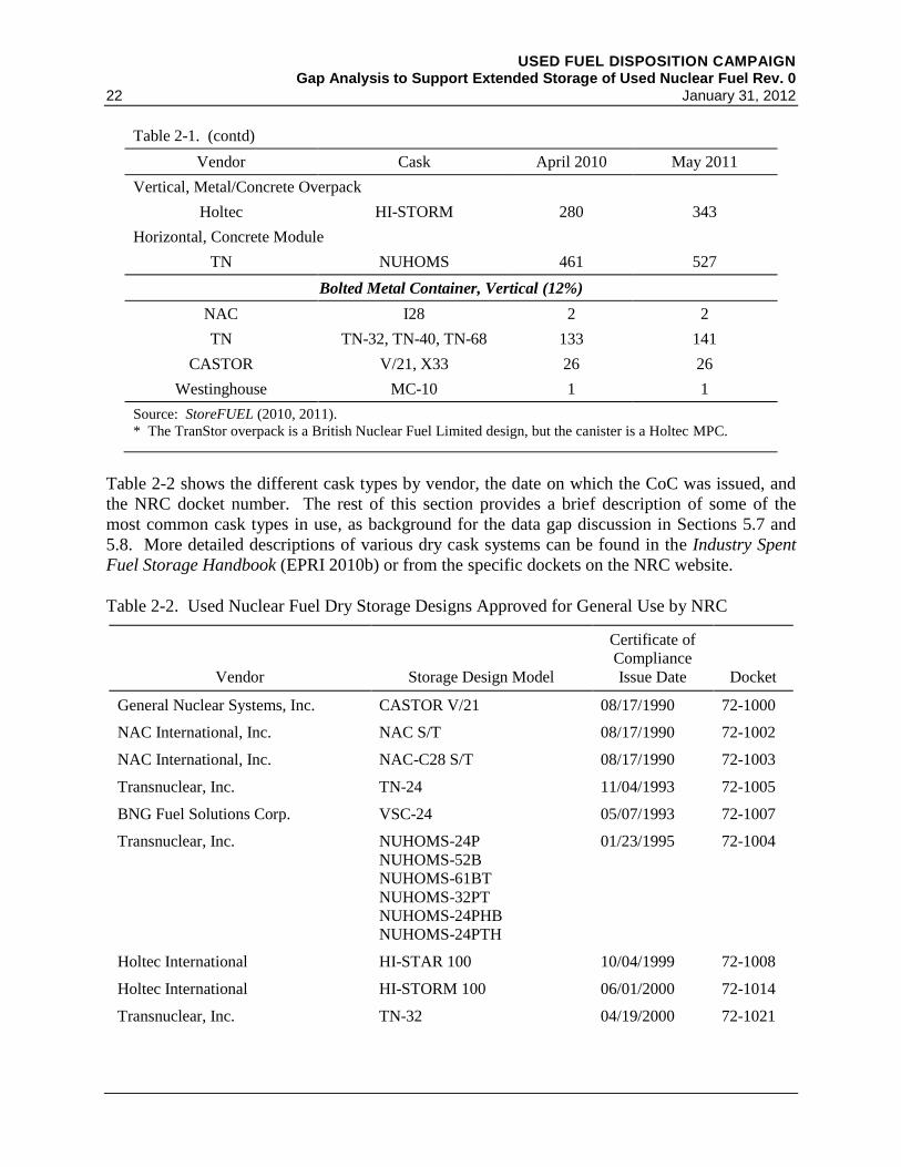
USED FUEL DISPOSITION CAMPAIGN Gap Analysis to Support Extended Storage of Used Nuclear Fuel Rev. 0
22 January 31, 2012
Table 2-1. (contd)
Vendor Cask April 2010 May 2011
Vertical, Metal/Concrete Overpack
Holtec HI-STORM 280 343
Horizontal, Concrete Module
TN NUHOMS 461 527
Bolted Metal Container, Vertical (12%)
NAC I28 2 2
TN TN-32, TN-40, TN-68 133 141
CASTOR V/21, X33 26 26
Westinghouse MC-10 1 1
Source: StoreFUEL (2010, 2011).
* The TranStor overpack is a British Nuclear Fuel Limited design, but the canister is a Holtec MPC.
Table 2-2 shows the different cask types by vendor, the date on which the CoC was issued, and
the NRC docket number. The rest of this section provides a brief description of some of the
most common cask types in use, as background for the data gap discussion in Sections 5.7 and
5.8. More detailed descriptions of various dry cask systems can be found in the Industry Spent
Fuel Storage Handbook (EPRI 2010b) or from the specific dockets on the NRC website.
Table 2-2. Used Nuclear Fuel Dry Storage Designs Approved for General Use by NRC
Vendor Storage Design Model
Certificate of
Compliance
Issue Date Docket
General Nuclear Systems, Inc. CASTOR V/21 08/17/1990 72-1000
NAC International, Inc. NAC S/T 08/17/1990 72-1002
NAC International, Inc. NAC-C28 S/T 08/17/1990 72-1003
Transnuclear, Inc. TN-24 11/04/1993 72-1005
BNG Fuel Solutions Corp. VSC-24 05/07/1993 72-1007
Transnuclear, Inc. NUHOMS-24P
NUHOMS-52B
NUHOMS-61BT
NUHOMS-32PT
NUHOMS-24PHB
NUHOMS-24PTH
01/23/1995 72-1004
Holtec International HI-STAR 100 10/04/1999 72-1008
Holtec International HI-STORM 100 06/01/2000 72-1014
Transnuclear, Inc. TN-32 04/19/2000 72-1021
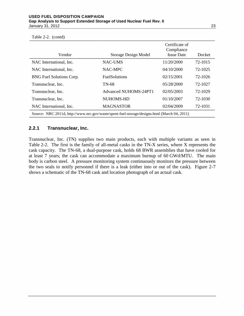
USED FUEL DISPOSITION CAMPAIGN Gap Analysis to Support Extended Storage of Used Nuclear Fuel Rev. 0 January 31, 2012 23
Table 2-2. (contd)
Vendor Storage Design Model
Certificate of
Compliance
Issue Date Docket
NAC International, Inc. NAC-UMS 11/20/2000 72-1015
NAC International, Inc. NAC-MPC 04/10/2000 72-1025
BNG Fuel Solutions Corp. FuelSolutions 02/15/2001 72-1026
Transnuclear, Inc. TN-68 05/28/2000 72-1027
Transnuclear, Inc. Advanced NUHOMS-24PT1 02/05/2003 72-1029
Transnuclear, Inc. NUHOMS-HD 01/10/2007 72-1030
NAC International, Inc. MAGNASTOR 02/04/2009 72-1031
Source: NRC 2011d, http://www.nrc.gov/waste/spent-fuel-storage/designs.html (March 04, 2011)
2.2.1 Transnuclear, Inc.
Transnuclear, Inc. (TN) supplies two main products, each with multiple variants as seen in
Table 2-2. The first is the family of all-metal casks in the TN-X series, where X represents the
cask capacity. The TN-68, a dual-purpose cask, holds 68 BWR assemblies that have cooled for
at least 7 years; the cask can accommodate a maximum burnup of 60 GWd/MTU. The main
body is carbon steel. A pressure monitoring system continuously monitors the pressure between
the two seals to notify personnel if there is a leak (either into or out of the cask). Figure 2-7
shows a schematic of the TN-68 cask and location photograph of an actual cask.

USED FUEL DISPOSITION CAMPAIGN Gap Analysis to Support Extended Storage of Used Nuclear Fuel Rev. 0
24 January 31, 2012
Figure 2-7. Transnuclear TN-68 Storage/Transport Cask. Schematic (left) and photo (right)
(Photos courtesy of Transnuclear, Inc.; reprinted with permission)
The NUHOMS system by TN is the most widely used DCSS in the United States. It consists of
a welded stainless steel DSC with an internal fuel basket and a concrete HSM that provides
radiation shielding and protects the canister from the environment. A transfer cask is used to
move the canister between the fuel handling facility and the HSM. A hydraulic ram is used to
push the canister into the HSM (Figure 2.8). There are multiple NUHOMS dry canister designs,
which can hold up to 24 or 32 PWR assemblies or up to 61 BWR assemblies. Some designs can
accommodate a maximum burnup of 62 GWd/MTU with between 3 and 10 years of cooling time
in the pool prior to being loaded in the canister. Figure 2-9 shows NUHOMS DSCs emplaced in
HSMs.
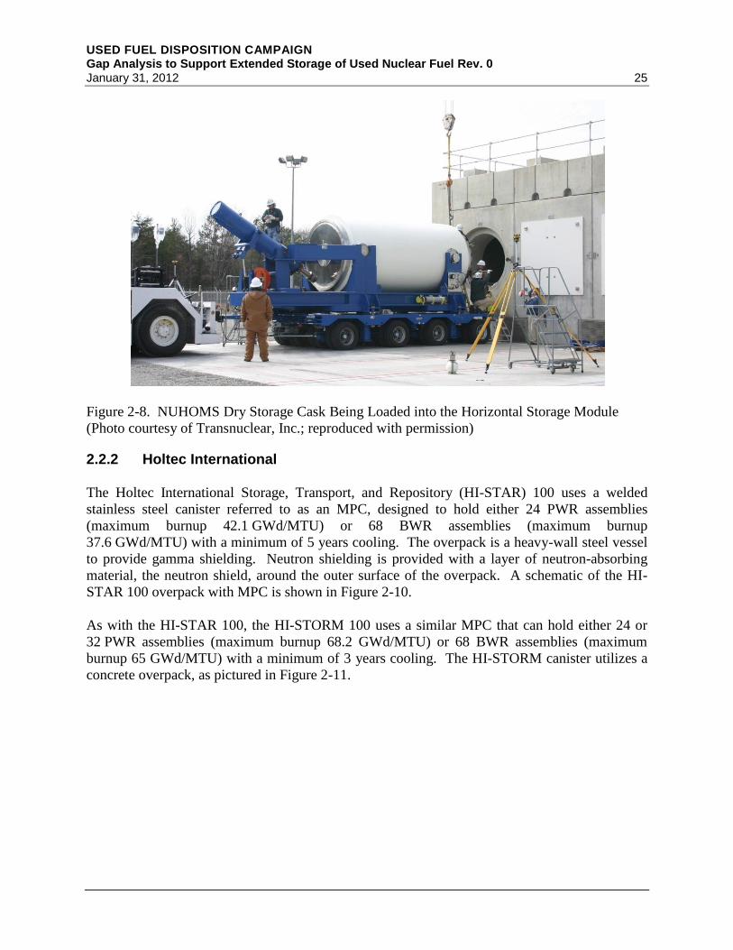
USED FUEL DISPOSITION CAMPAIGN Gap Analysis to Support Extended Storage of Used Nuclear Fuel Rev. 0 January 31, 2012 25
Figure 2-8. NUHOMS Dry Storage Cask Being Loaded into the Horizontal Storage Module
(Photo courtesy of Transnuclear, Inc.; reproduced with permission)
2.2.2 Holtec International
The Holtec International Storage, Transport, and Repository (HI-STAR) 100 uses a welded
stainless steel canister referred to as an MPC, designed to hold either 24 PWR assemblies
(maximum burnup 42.1 GWd/MTU) or 68 BWR assemblies (maximum burnup
37.6 GWd/MTU) with a minimum of 5 years cooling. The overpack is a heavy-wall steel vessel
to provide gamma shielding. Neutron shielding is provided with a layer of neutron-absorbing
material, the neutron shield, around the outer surface of the overpack. A schematic of the HI-
STAR 100 overpack with MPC is shown in Figure 2-10.
As with the HI-STAR 100, the HI-STORM 100 uses a similar MPC that can hold either 24 or
32 PWR assemblies (maximum burnup 68.2 GWd/MTU) or 68 BWR assemblies (maximum
burnup 65 GWd/MTU) with a minimum of 3 years cooling. The HI-STORM canister utilizes a
concrete overpack, as pictured in Figure 2-11.

USED FUEL DISPOSITION CAMPAIGN Gap Analysis to Support Extended Storage of Used Nuclear Fuel Rev. 0
26 January 31, 2012
Figure 2-9. NUHOMS Dry Storage Casks Emplaced in Concrete Horizontal Storage Modules at
the Idaho National Laboratory Independent Spent Fuel Storage Installation
(Photo courtesy of Idaho National Laboratory)
Figure 2-10. HI-STAR 100 Schematic of Overpack with MPC Partially Inserted (left) and Casks
in Storage (right)
(Images courtesy of Holtec International; reprinted with permission)
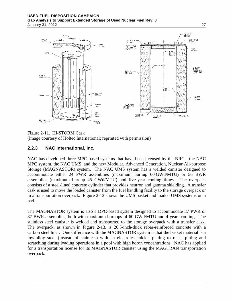
USED FUEL DISPOSITION CAMPAIGN Gap Analysis to Support Extended Storage of Used Nuclear Fuel Rev. 0 January 31, 2012 27
Figure 2-11. HI-STORM Cask
(Image courtesy of Holtec International; reprinted with permission)
2.2.3 NAC International, Inc.
NAC has developed three MPC-based systems that have been licensed by the NRC—the NAC
MPC system, the NAC UMS, and the new Modular, Advanced Generation, Nuclear All-purpose
Storage (MAGNASTOR) system. The NAC UMS system has a welded canister designed to
accommodate either 24 PWR assemblies (maximum burnup 60 GWd/MTU) or 56 BWR
assemblies (maximum burnup 45 GWd/MTU) and five-year cooling times. The overpack
consists of a steel-lined concrete cylinder that provides neutron and gamma shielding. A transfer
cask is used to move the loaded canister from the fuel handling facility to the storage overpack or
to a transportation overpack. Figure 2-12 shows the UMS basket and loaded UMS systems on a
pad.
The MAGNASTOR system is also a DPC-based system designed to accommodate 37 PWR or
87 BWR assemblies, both with maximum burnups of 60 GWd/MTU and 4 years cooling. The
stainless steel canister is welded and transported to the storage overpack with a transfer cask.
The overpack, as shown in Figure 2-13, is 26.5-inch-thick rebar-reinforced concrete with a
carbon steel liner. One difference with the MAGNASTOR system is that the basket material is a
low-alloy steel (instead of stainless) with an electroless nickel plating to resist pitting and
scratching during loading operations in a pool with high boron concentrations. NAC has applied
for a transportation license for its MAGNASTOR canister using the MAGTRAN transportation
overpack.

USED FUEL DISPOSITION CAMPAIGN Gap Analysis to Support Extended Storage of Used Nuclear Fuel Rev. 0
28 January 31, 2012
Figure 2-12. NAC UMS Basket (left) and Loaded UMS Systems (right)
(Photos courtesy of NAC International, Inc.; reprinted with permission)
2.3 Regulation and Guidance of UNF Storage
The regulatory requirements for site-specific and general licenses for storage of used nuclear fuel
are discussed in this section. Also provided is a listing of review plans as well as NRC staff and
industry guidance relevant to extended storage of used nuclear fuel. This NRC document
collection was used extensively as a guide in identification of issues, prioritization of issues, and
final selection of data gaps that are important to licensing.
2.3.1 Regulation
The NRC currently licenses storage of UNF in dry storage systems and in pools (other than
onsite reactor spent nuclear fuel pools) under the regulation of 10 CFR 72. Under Part 72,
applicants can pursue a site-specific license or a general license. The regulations for a site-
specific license govern both at-reactor ISFSIs and away-from-reactor storage facilities. In 1990,
the NRC added provisions for a general license under 10 CFR 72, Subpart K, which authorized
Part 50 licensees to store used nuclear fuel at their reactor sites in NRC-certified storage casks
without filing licensing documents, as would be needed for a site-specific application. As
required in 10 CFR 72.212, to use casks under a general license, the applicant must demonstrate
that the conditions in the casks’ CoCs are met and that the site design, site-specific
environmental conditions, and design basis accidents including natural phenomena are bounded
by the terms of the general license. In cases where the design conditions fall outside the design
envelope of the cask CoC, such as high seismic areas, a site-specific license is needed.

USED FUEL DISPOSITION CAMPAIGN Gap Analysis to Support Extended Storage of Used Nuclear Fuel Rev. 0 January 31, 2012 29
Figure 2-13. NAC MAGNASTOR Basket Inserted in Canister (upper left); MAGNASTOR
Vertical Concrete Casks (VCCs) (upper right); Schematic of the MAGNASTOR VCC (bottom).
(Images courtesy of NAC International, Inc.; reprinted with permission)
There are interfaces between 10 CFR 72 and other rules, such as 10 CFR 50, which governs
some of the operations associated with loading of storage casks, and 10 CFR 71, which governs
transportation operations. Some of the interfaces depend on the type of license (general versus
site-specific) and the type of safety analysis. For example, the criticality safety analyses for dry
storage casks while being loaded in a 10 CFR 50 spent fuel pool are governed by 10 CFR 72.

USED FUEL DISPOSITION CAMPAIGN Gap Analysis to Support Extended Storage of Used Nuclear Fuel Rev. 0
30 January 31, 2012
The initial licenses granted under 10 CFR 72.42 (a) were limited to 20 years. However, effective
May 17, 2011, 10 CFR 72.42(a) was officially changed to allow an initial license period of up to
40 years and license extensions of up to 40 years.
The NRC recently issued an updated Waste Confidence Rule (10 CFR Part 51.23(a)), which
states “Commission finds reasonable assurance that…spent fuel...can be stored safely…for at
least 60 years beyond the licensed life for operation (which may include the term of a revised or
renewed license) of that reactor in a combination of storage in its spent fuel storage basin and
either onsite or offsite independent spent fuel storage installations.” With a 60-year reactor life,
the Waste Confidence Rule states the Commission’s confidence that fuel can be stored for up to
120 years.
2.3.2 Review Plans
The NRC conducts its review of UNF storage applications under two review plans:
NUREG-1536 (NRC 2010b) for dry storage systems and NUREG-1567 (NRC 2000) for storage
facilities. NUREG-1927 (NRC 2011c) is a review plan for renewal of ISFSI licenses and dry
cask storage systems CoCs.
2.3.3 Interim Staff Guidance
NRC guidance regarding UNF storage and transportation is provided in a series of Spent Fuel
Storage and Transportation (SFST) Interim Staff Guidance (ISG) documents. The following is a
listing of select ISGs with brief descriptions relevant to extended dry storage:
SFST-ISG-1, Rev. 2, “Damaged Fuel” provides guidance on used nuclear fuel classification
as intact, undamaged, or damaged prior to placement in dry storage.
SFST-ISG-2, Rev. 1, “Fuel Retrievability” provides clarification on the meaning of fuel
retrieval with normal means.
SFST-ISG-3, Rev. 0, “Post Accident Recovery and Compliance with 10 CFR 72.122”
provides clarification that retrieval with normal means does not apply to design basis
accidents.
SFST-ISG-5, Rev. 1, “Confinement Evaluation” provides guidance on confinement and
monitoring requirements for welded and bolted systems.
SFST-ISG-8, Rev. 2, “Burnup Credit in the Criticality Safety Analyses of PWR Spent Fuel in
Transport and Storage Casks” provides guidance on validation of burnup credit for criticality
safety analyses for storage and transportation applications, including type of data needed to
validate computer models as well as burnup measurement requirements.
SFST-ISG-9, Rev. 1, “Storage of Components Associated With Fuel Assemblies” provides
guidance on the types of components that can be stored with fuel assemblies, such as control
rods or burnable poison rods, as well as the associated required analyses.
USED FUEL DISPOSITION CAMPAIGN Gap Analysis to Support Extended Storage of Used Nuclear Fuel Rev. 0 January 31, 2012 31
SFST-ISG-10, Rev. 1, “Alternatives to the ASME Code” provides guidance on the American
Society of Mechanical Engineers (ASME) Code Section III to the design and fabrication of
dry cask storage systems. It also provides guidance on the required documentation for
application of alternatives to the ASME code for ITS SSCs.
SFST-ISG-11, Rev. 3, “Cladding Considerations for the Transportation and Storage of Spent
Fuel” provides guidance on the required analysis and operational limits for fuel with burnup
exceeding 45 GWd/MTU. It also defines the fuel cladding temperature limits for cask
loading, vacuum drying, transportation, and storage operations.
SFST-ISG-12, Rev. 1, “Buckling of Irradiated Fuel Under Bottom End Drop Conditions”
provides guidance on the analysis methodology as well as material and structural parameters
for fuel assemblies in a cask drop scenario.
SFST-ISG-13, Rev. 0, “Real Individual” clarifies the reference in 10 CFR 72.104 to a real
individual and describes how to perform dose evaluations beyond the controlled area.
SFST-ISG-14, Rev. 0, “Supplemental Shielding” provides guidance on the use of
supplemental shielding that maybe used at ISFSI sites to meet the dose limits for normal
conditions of operation in 10 CFR 72.104(a).
SFST-ISG-15, Rev. 0, “Materials Evaluation” provides guidance for the review of dry
storage systems materials.
SFST-ISG-16, Rev. 0, “Emergency Planning” provides guidance for reviewing emergency
plans for ISFSIs.
SFST-ISG-18, Rev. 1. “The Design and Testing of Lid Welds on Austenitic Stainless Steel
Canisters as the Confinement Boundary for Spent Fuel Storage” provides guidance for the
design and testing of the closure welds of welded stainless steel canisters.
SFST-ISG-19, Rev. 0, “Moderator Exclusion Under Hypothetical Accident Conditions and
Demonstrating Subcriticality of Spent Fuel Under the Requirements of 10 CFR 71.55(e)”
provides guidance for demonstrating subcriticality on the basis of moderator exclusion for
hypothetical accident conditions.
SFST-ISG-21, Draft, “Use of Computational Modeling Software” provides guidance on the
use and validation of computational modeling software in thermal and structural analyses.
SFST-ISG-22, Rev. 0, “Potential Rod Splitting Due to Exposure to an Oxidizing Atmosphere
During Short-Term Cask Loading Operations in LWR or Other Uranium Oxide Based Fuel”
provides guidance on the operating procedures, technical specification, and licensing
documentation to support the analysis for potential cladding splitting if exposed to an
oxidizing environment.
SFST-ISG-23, Rev. 0, “Application of ASTM Standard Practice C1671-07 When Performing
Technical Reviews of Spent Fuel Storage and Transportation Packaging Licensing Actions”
provides guidance on the use of American Society of Testing and Materials (ASTM)
Standard Designation C1671-07 (ASTM C1671-07 2007a) in evaluating licensing actions
that rely upon borated neutron poison materials for maintaining subcriticality in storage and
transportation packages.

USED FUEL DISPOSITION CAMPAIGN Gap Analysis to Support Extended Storage of Used Nuclear Fuel Rev. 0
32 January 31, 2012
SFST-ISG-25, Draft, “Pressure Test and Helium Leakage Test of the Confinement Boundary
for Spent Fuel Storage Canister” provides guidance for confinement boundary helium leak
testing and ASME Code required pressure testing.
2.3.4 Additional Guidance Documents
The following is a list of select regulatory guides, NUREG/CRs, and industry standards that
provide analysis guidance on various topics that pertain to dry storage of used nuclear fuel:
Regulatory Guide 3.48, “Standard Format and Content for the Safety Analysis Report for an
Independent Spent Fuel Storage Installation or Monitored Retrievable Storage Installation
(Dry Storage)”
Regulatory Guide 3.50, “Standard Format and Content for a License Application to Store
Spent Fuel and High-Level Radioactive Waste”
Regulatory Guide 3.53, “Applicability of Existing Regulatory Guides to the Design and
Operation of an Independent Spent Fuel Storage Installation”
Regulatory Guide 3.54, “Spent Fuel Heat Generation in an Independent Spent Fuel Storage
Installation”
Regulatory Guide 3.60, “Design of an Independent Spent Fuel Storage Installation (Dry
Storage)”
Regulatory Guide 3.62, “Standard Format and Content for the Safety Analysis Report for
Onsite Storage of Spent Fuel Storage Casks”
Regulatory Guide 3.72, “Guidance for Implementation of 10 CFR 72.48, Changes, Tests, and
Experiments”
Regulatory Guide 3.73, “Site Evaluations and Design Earthquake Ground Motion for Dry
Cask Independent Spent Fuel Storage and Monitored Retrievable Storage Installations”
NUREG/CR-6361, Criticality Benchmark Guide for Light-Water-Reactor Fuel in
Transportation and Storage Packages, March 1997
NUREG/CR-6700, Nuclide Importance to Criticality Safety, Decay Heating, and Source
Terms Related to Transport and Interim Storage of High-Burnup LWR Fuel, January 2001
NUREG/CR-6701, Review of Technical Issues Related to Predicting Isotopic Compositions
and Source Terms for High-Burnup LWR Fuel, January 2001
NUREG/CR-6716, Recommendations on Fuel Parameters for Standard Technical
Specifications for Spent Fuel Storage Casks, March 2001
NUREG/CR-6759, Parametric Study of the Effect of Control Rods for PWR Burnup Credit,
February 2002
NUREG/CR-6760, Study of the Effect of Integral Burnable Absorbers for PWR Burnup
Credit, March 2002
USED FUEL DISPOSITION CAMPAIGN Gap Analysis to Support Extended Storage of Used Nuclear Fuel Rev. 0 January 31, 2012 33
NUREG/CR-6761, Parametric Study of the Effect of Burnable Poison Rods for PWR Burnup
Credit, March 2002
NUREG/CR-6801, Recommendations for Addressing Axial Burnup in PWR Burnup Credit
Analyses, March 2003
NUREG/CR-6802, Recommendations for Shielding Evaluations for Transport & Storage
Packages, May 2003
NUREG/CR-6835, Effects of Fuel Failure on Criticality Safety and Radiation Dose for Spent
Fuel Casks, September 2003
ANSI/ANS 57.9-1992-R2000, “Design Criteria for an Independent Spent Fuel Storage
Installation (Dry Storage Type).”
2.4 Application of Regulatory Requirements and Guidance
This section summarizes key general regulatory performance requirements as well as associated
guidance in review plans and ISGs for the safety functional areas of dry storage systems and
storage facilities.
2.4.1 Dry Storage Systems SSCs and Safety Functional Areas
10 CFR 72.24(d) requires that a license application safety analysis report (SAR) for an ISFSI
contain “…an analysis and evaluation of the design and performance of structures, systems, and
components important to safety, with the objective of assessing the impact on public health and
safety resulting from operation of the ISFSI.” The list of SSCs is unique to each dry cask storage
system; however, the SSCs are grouped into the following ten categories for purposes of this
report:
1. fuel
2. cladding
3. fuel assembly hardware
4. fuel baskets
5. neutron poisons
6. neutron shields
7. container/canister
8. overpack or storage module
9. pad
10. monitoring systems.
These SSCs are categorized as ITS or non-ITS based on the safety functions they perform for the
ISFSI. The general safety functions of the ISFSI are listed in the definition of ITS SSCs in

USED FUEL DISPOSITION CAMPAIGN Gap Analysis to Support Extended Storage of Used Nuclear Fuel Rev. 0
34 January 31, 2012
10 CFR 72: “(1) To maintain the conditions required to store spent fuel … safely; (2) To prevent
damage to the spent fuel … [and] waste container during handling and storage; or (3) To provide
reasonable assurance that spent fuel … can be received, handled, packaged, stored, and retrieved
without undue risk to the health and safety of the public.” To meet these regulatory
requirements, Section 4.4.3.1 in NUREG-1567 states “The applicant must identify design criteria
and design bases for all SSCs determined to be important to safety. The basic design criteria for
SSCs which are important to safety shall: maintain subcriticality, maintain confinement, ensure
radiation rates and doses for workers and public do not exceed acceptable levels and remain as
low as is reasonably achievable (ALARA), maintain retrievability, and provide for heat removal
(as necessary to meet the above criteria).” Therefore, the key safety functional areas for dry
storage are
1. retrievability
2. thermal performance
3. confinement
4. radiation protection
5. subcriticality.
The following sections discuss in detail the regulatory requirements and associated guidance for
these five safety functional areas.
2.4.2 Retrievability (Including Thermal Performance)
10 CFR 72.122(h)(5) states “The high level radioactive waste and reactor related GTCC waste
must be packaged in a manner that allows handling and retrievability without the release of
radioactive materials to the environment or radiation exposures in excess of Part 20 limits...”
10 CFR 72.122(l) states “Storage systems must be designed to allow ready retrieval of spent fuel,
high-level radioactive waste, and reactor-related GTCC waste for further processing or disposal.”
SFST-ISG-2 (NRC 2010a) defines ready retrieval as “The staff considers a fuel assembly to be
“ready retrievable” if it remains structurally sound (i.e., no gross degradation) and could be
handled by normal means (i.e., does not pose operational safety problems during removal).”
SFST-ISG-2 further defines “normal means” as “the ability to move the fuel assembly and its
contents by the use of the crane and grapple used to move undamaged assemblies at the point of
cask loading. The addition of special tooling or modifications to the assembly to make the
assembly suitable for lifting with crane and grapple does not preclude the handling from being
considered “normal means.””
SFST-ISG-3 (NRC 1998a) clarifies that “10 CFR 72.122(l) applies to normal and off-normal
design conditions and not to accidents.”
To meet the retrievability requirements described above, a SAR must demonstrate that fuel can
be retrievable by preserving the loading analysis bases. Used nuclear fuel must be classified
prior to placement in a storage cask as damaged, undamaged, or intact. Damaged fuel would be
placed in a damaged fuel can. Fuel classified as intact or undamaged must remain undamaged to

USED FUEL DISPOSITION CAMPAIGN Gap Analysis to Support Extended Storage of Used Nuclear Fuel Rev. 0 January 31, 2012 35
continue to meet the loading and retrieval analysis bases. The current basis relied upon to
demonstrate that fuel classification does not change during storage (20–60 years) is by
maintaining the fuel in an inert atmosphere and within the temperature limits recommended in
SFST-ISG-11 (NRC 2003a). The most important limits in SFST-ISG-11 are as follows:
1. For all fuel burnups (low and high), the maximum calculated fuel cladding temperature
should not exceed 400°C (752°F) for normal conditions of storage and short-term loading
operations (e.g., drying, backfilling with inert gas, and transfer of the cask to the storage
pad).
However, for low burnup fuel, a higher short-term temperature limit may be used, if the
applicant can show by calculation that the best estimate cladding hoop stress is equal to or
less than 90 MPa (13,053 psi) for the temperature limit proposed.
2. During loading operations, repeated thermal cycling (repeated heatup/cooldown cycles) may
occur but should be limited to less than 10 cycles, with cladding temperature variations that
are less than 65°C (117°F) each.
3. For off-normal and accident conditions, the maximum cladding temperature should not
exceed 570°C (1058°F).
SFST-ISG-1 (NRC 2007a) provides guidance on UNF classification. The performance-based
definition of damaged SNF provided in this ISG minimizes the quantity of damaged fuel
requiring alternative handling paths while still addressing applicable system-related regulations
concerning criticality control, thermal limitations, structural integrity, confinement, and
shielding. Definitions from SFST-ISG-1 that are relevant to fuel classification are
intact SNF – Any fuel that can fulfill all fuel-specific and system-related functions and that is
not breached. Note that all intact SNF is undamaged, but not all undamaged fuel is intact,
because under most situations, breached spent fuel rods that are not grossly breached will be
considered undamaged.
undamaged SNF – SNF that can meet all fuel-specific and system-related functions.
Undamaged fuel may be breached. Fuel assembly classified as undamaged SNF may have
“assembly defects.”
grossly breached spent fuel rod – A breach in spent fuel cladding that is larger than a pinhole
leak or a hairline crack. An acceptable examination for a gross breach is a visual
examination that has the capability to determine the fuel pellet surface may be seen through
the breached portion of the cladding. Alternatively, review of reactor operating records may
provide evidence of the presence of heavy metal isotopes indicating that a fuel rod is grossly
breached. “Gross breaches should be considered to be any cladding breach greater than
1 millimeter.”
damaged SNF – Any fuel rod or fuel assembly that cannot fulfill its fuel-specific or system-
related functions.
USED FUEL DISPOSITION CAMPAIGN Gap Analysis to Support Extended Storage of Used Nuclear Fuel Rev. 0
36 January 31, 2012
2.4.3 Confinement
Maintaining confinement in dry storage systems for normal operations, off-normal conditions,
and design basis accidents is required in 10 CFR 72.236 (l), which states “The spent fuel storage
cask and its systems important to safety must be evaluated, by appropriate tests or by other
means acceptable to the NRC, to demonstrate that they will reasonably maintain confinement of
radioactive material under normal, off-normal, and credible accident conditions.”
Confinement describes the safety function in NUREG-1536 as “Prevent unacceptable release of
contained radioactive material.” The primary objectives of the confinement requirement are to
provide radiological protection and maintain cladding classification. Confinement systems are
defined in 10 CFR 72.3 as “those systems, including ventilation, that act as barriers between
areas containing radioactive substances and the environment.” The definition of confinement in
NUREG-1536 is “the ability to prevent the release of radioactive substances into the
environment.” From these definitions, it is clear that the container is a confinement barrier in an
ISFSI, but it is not as clear whether the NRC considers cladding to be a confinement barrier.
10 CFR 72.122(h) states “Confinement barriers and systems: (1) The spent fuel cladding must
be protected during storage against degradation that leads to gross ruptures or the fuel must be
otherwise confined such that degradation of the fuel during storage will not pose operational
safety problems with respect to its removal from storage. This may be accomplished by canning
of consolidated fuel rods or unconsolidated assemblies or other means as appropriate.” This
implies that the NRC considers the cladding to be a confinement barrier only so far as it prevents
release of solid radioactive material from gross ruptures; however, NUREG-1536 Section 8.6
defines gross breaches as any cladding breach greater than 1 millimeter so most solid material
will continue to be confined. The NRC does not require that cladding be intact or unbreached.
As discussed in Section 2.4.2, the interim staff guidance on damaged fuel (SFST-ISG-1)
provides clarification by classifying spent nuclear fuel as (1) damaged, (2) undamaged, or
(3) intact.
Because the NRC does not require that cladding be intact or unbreached, it is not a full
confinement barrier for all radionuclides in an ISFSI. Fission gases such as xenon may be
released from the fuel through cladding pin holes. Even intact cladding has radionuclides on the
outside of the fuel rods such as 60
Co that may be released if deposits are knocked off. For this
reason, this report does not treat the cladding as a confinement barrier during dry storage.
However, during retrieval operations, cladding is the primary, if not only, confinement barrier
(see Section 2.4.2). In addition, to meet the retrievability requirements described in
Section 2.4.2, a SAR must demonstrate that fuel can be retrievable by preserving the loading
analysis bases, meaning that if cladding is classified undamaged when loaded into a dry storage
cask, it must remain undamaged throughout the storage period.
Confirming that confinement is maintained through active monitoring is required per 10 CFR
72.122(h)(4), which states “Storage confinement systems must have the capability for continuous
monitoring in a manner such that the licensee will be able to determine when corrective action
needs to be taken to maintain safe storage conditions. For dry spent fuel storage, periodic
monitoring is sufficient provided that periodic monitoring is consistent with the dry spent fuel

USED FUEL DISPOSITION CAMPAIGN Gap Analysis to Support Extended Storage of Used Nuclear Fuel Rev. 0 January 31, 2012 37
storage cask design requirements. The monitoring period must be based upon the spent fuel
storage cask design requirements.”
Based on the gained confidence thus far, the NRC staff clarified that monitoring confinement is
required only for bolted but not for welded closures. SFST-ISG-5 (NRC 1998b) states that the
“NRC staff has found that casks closed entirely by welding do not require monitoring. However,
for casks with bolted closures, the staff has found that a seal monitoring system has been needed
in order to adequately demonstrate that seals can function and maintain a helium atmosphere for
the 20-year license period.” With extended storage beyond 60 years, the monitoring needs
become more important.
2.4.4 Radiation Protection
This section discusses protection from direct exposure to radiation. Confinement and protection
from release of radionuclides are discussed in Section 2.4.3. For onsite occupational radiation
protection, 10 CFR 72.24 states “Each application for a license under this part must include a
Safety Analysis Report describing…(e) The means for controlling and limiting occupational
radiation exposures within the limits given in part 20 of this chapter, and for meeting the
objective of maintaining exposures as low as is reasonably achievable.”
10 CFR 20.1201 provides the annual occupational dose limits for adults as “The total effective
dose equivalent being equal to 5 rems (0.05 Sv)” or “The sum of the deep-dose equivalent and
the committed dose equivalent to any individual organ or tissue other than the lens of the eye
being equal to 50 rems (0.5 Sv).” Licensees demonstrate compliance with these limits with a
significant margin based on several layers of fixed and portable gamma and neutron shielding,
conservative or bounding estimates of source terms, maintaining distance from sources, and
limiting exposure times.
For offsite public radiation protection for normal and off-normal conditions, 10 CFR 72.104(a)
states “During normal operations and anticipated occurrences, the annual dose equivalent to any
real individual who is located beyond the controlled area must not exceed 0.25 mSv (25 mrem)
to the whole body, 0.75 mSv (75 mrem) to the thyroid and 0.25 mSv (25 mrem) to any other
critical organ.” For offsite public radiation protection under design basis accidents, 10 CFR
72.106(b) states that “Any individual located on or beyond the nearest boundary of the controlled
area may not receive from any design basis accident the more limiting of a total effective dose
equivalent of 0.05 Sv (5 rem), or the sum of the deep-dose equivalent and the committed dose
equivalent to any individual organ or tissue (other than the lens of the eye) of 0.5 Sv (50 rem).
The lens dose equivalent may not exceed 0.15 Sv (15 rem) and the shallow dose equivalent to
skin or any extremity may not exceed 0.5 Sv (50 rem). The minimum distance from the spent
fuel, high-level radioactive waste, or reactor-related GTCC waste handling and storage facilities
to the nearest boundary of the controlled area must be at least 100 meters.”
The licensing basis for current ISFSIs is that there are no normal operating conditions, off-
normal conditions, or design basis accidents that result in significant reduction in shielding
(mainly gamma) effectiveness to impact these limits. In addition, because of the distance
between the dry storage casks and the site boundary, direct exposure is an insignificant

USED FUEL DISPOSITION CAMPAIGN Gap Analysis to Support Extended Storage of Used Nuclear Fuel Rev. 0
38 January 31, 2012
contributor to offsite public dose. This may need to be reevaluated as more casks are stored in
current locations.
2.4.5 Subcriticality
10 CFR 72.124 establishes the criteria for subcriticality of used nuclear fuel handling, packaging,
transfer, and storage systems. It requires that before a nuclear criticality accident is possible, at
least two unlikely, independent, and concurrent or sequential changes must occur in the
conditions essential to nuclear criticality safety, which is traditionally known as the double
contingency principle. The four operations/conditions with unique criticality safety bases for dry
storage are
loading operations
drying operations
cask movement and storage conditions
retrieval operations.
Because some casks are intended to be transported without fuel repackaging, subcriticality for
transportation is also discussed. The subcriticality bases for each operation/condition are
discussed in the following sections.
2.4.5.1 Loading Operations
Maintaining subcriticality during loading operations in a spent nuclear fuel pool is governed by
both 10 CFR 50.68 and 10 CFR 72.124. The criteria for maintaining subcriticality while the
assemblies are in the pool storage racks and in transit to a cask are governed by 10 CFR 50.68.
Subcriticality for these operations is generally based on one or a combination of the following:
fixed neutron absorbers in fuel pool racks
separation between fuel assemblies (e.g., flux trap gap)
neutron poison or moderator displacers inserted in the guide tubes (e.g., used burnable poison
rods, used control rods, or dummy rods)
burnup credit by taking credit for the reduction in fuel fissile material concentration and the
presence of actinide and fission product neutron absorbers
soluble boron, which is available only in PWR spent fuel pools – Note that current practice
does not credit both assembly burnup and soluble boron.
Once a fuel assembly has been inserted inside a storage cask, while still in the fuel pool, the
criticality safety basis can be different. 10 CFR 50.68 was revised in 2006 to reflect this
distinction. For example, soluble boron could be credited for demonstrating subcriticality in the
loaded cask with a fresh fuel assumption for assemblies that may have credited burnup to
demonstrate subcriticality in the pool racks.

USED FUEL DISPOSITION CAMPAIGN Gap Analysis to Support Extended Storage of Used Nuclear Fuel Rev. 0 January 31, 2012 39
2.4.5.2 Drying Operations
During drying operations, subcriticality is generally maintained by demonstrating that there is no
credible scenario that would result in availability of water that could enter the unsealed storage
cask. This analysis basis and credited design features are important in particular for those casks
loaded with assemblies that rely on soluble boron for demonstrating subcriticality during loading
operations.
2.4.5.3 Cask Movement Operations and Storage Conditions
Once a cask has been dried and inerted, the basis for subcriticality is moderator exclusion.
Safety Analysis Reports demonstrate that there is no credible scenario during normal operations,
off-normal conditions, and design basis accidents including natural phenomena, that results in
container (or confinement) breach.
2.4.5.4 Retrieval Operations
Subcriticality is ensured for future retrieval operations by demonstrating that the loading
subcriticality bases and design features are not significantly altered during storage. These bases
and design features include
continued neutron absorber efficacy – 10 CFR 72.124 states “For dry spent fuel storage
systems, the continued efficacy may be confirmed by a demonstration or analysis before use,
showing that significant degradation of the neutron absorbing materials cannot occur over the
life of the facility.” This includes demonstrating that the neutron poison density and
distribution are not significantly reduced and that the neutron absorber material remains
intact without developing any cracks.
no changes in fuel classification – If fuel is classified as undamaged for loading operations, it
must be demonstrated that the cladding does not become damaged during storage. Note that
developing holes and cracks, even if larger than pin holes and hairline cracks, may not
impact the subcriticality bases as long as it can be demonstrated that the fuel rods remain
intact. Alternatively, an analysis can be performed for the new fuel condition to demonstrate
that the new configuration is similar or lower in reactivity compared to the initial loading
configuration.
maintenance of minimum required separation between fuel assemblies – Any reduction in
separation between fuel assemblies will increase neutronic coupling and decrease
effectiveness of neutron poisons.
Although current practice is to demonstrate that loading conditions are not sufficiently altered
during storage to change the subcriticality bases, a more risk-based evaluation and/or a retrieval
method that is different from the loading method could alleviate this requirement. For example,
if retrieval is performed in a dry environment or in a pool with a sufficiently high concentration
of soluble boron, demonstrating fixed neutron absorber efficacy, unaltered cladding condition,
and separation between fuel assemblies would not be necessary for demonstrating subcriticality.
USED FUEL DISPOSITION CAMPAIGN Gap Analysis to Support Extended Storage of Used Nuclear Fuel Rev. 0
40 January 31, 2012
2.4.5.5 Transportation
10 CFR 71.55 requires that “…a package used for the shipment of fissile material must be so
designed and constructed and its contents so limited that it would be subcritical if water were to
leak into the containment system, or liquid contents were to leak out of the containment system
so that….maximum reactivity of the fissile material would be attained.” The conditions
contributing to maximum reactivity include “most reactive credible configuration consistent with
the chemical and physical form of the material,” “Moderation by water to the most reactive
credible extent,” and “Close full reflection of the containment system by water on all sides.”
10 CFR 71.55 does allow for demonstrating subcriticality on the basis of moderator exclusion by
demonstrating “…that no single packaging error would permit leakage, and if appropriate
measures are taken before each shipment to ensure that the containment system does not leak.”
SFST-ISG-19 (NRC 2003b) provides guidance for demonstrating subcriticality on the basis of
moderator exclusion for hypothetical accident conditions.
Without moderator exclusion, the transportation subcriticality requirements that a transportable
dry storage cask/canister must meet are those for retrieval as described in Section 2.4.5.4, along
with demonstrating that the structural integrity of the cladding, neutron poisons, and fuel baskets
(i.e., maintaining minimum required separation between fuel assemblies) must be maintained
under normal conditions of transport and hypothetical accident conditions. In addition, for those
casks containing fuel assemblies that relied upon soluble boron credit for loading operations,
sufficient burnup must be credited to offset the level of soluble boron credit. The guidance for
burnup credit is provided in SFST-ISG-8 (NRC 2002).
USED FUEL DISPOSITION CAMPAIGN Gap Analysis to Support Extended Storage of Used Nuclear Fuel Rev. 0 January 31, 2012 41
3. METHODOLOGY
This section discusses the dry storage analysis conditions including those for normal operations
and off-normal conditions, along with the performance criteria for design basis accidents. This
section also discusses the stressors during dry storage and the methodology for identifying dry
storage SSCs degradation mechanisms as influenced by extended storage as well as the basis for
prioritizing additional data needs to evaluate those degradation mechanisms.
3.1 Analysis Conditions
In the license or CoC application, it must be demonstrated that the safety functions are
maintained for all normal, off-normal, and design basis accident conditions during which both
internal and external stressors (thermal, radiation, chemical and mechanical) may act on the dry
storage system. The license applications for ISFSIs, which must provide technical evidence to
the NRC that the safety functions will be maintained, include both time-specific and site-specific
design basis accidents in addition to normal and off-normal conditions. The regulatory safety
requirements may differ for the various analysis conditions as described in Section 2.4.
Normal conditions are defined in NUREG-1536 (NRC 2010b) and NUREG-1567 (NRC 2000) as
“Conditions that are intended operations, planned events, and environmental conditions, that are
known or reasonably expected to occur with high frequency during storage operations. The
maximum level of an event or condition is [sic] that expected to routinely occur. The cask
system is expected to remain fully functional and to experience no temporary or permanent
degradation from normal operations, events and conditions.”
Off-normal conditions are defined in NUREG-1536 and NUREG-1567 as “The maximum level
of an event or condition that although not occurring regularly can be expected to occur with
moderate frequency and for which there is a corresponding maximum specified resistance, limit
of response, or requirement for a given level of continuing capability… An independent spent
fuel storage installation structure, system, or component is expected to experience off-normal
events and conditions without permanent deformation or degradation of capability to perform its
full function (although operations may be suspended or curtailed during off-normal conditions)
over the full license period.” Off-normal conditions include
variations of temperatures beyond normal
failure of 10% of the fuel rods combined with off-normal temperatures
failure of one of the confinement boundaries
partial blockage of air vents
human error
out-of-tolerance equipment performance
equipment failure
USED FUEL DISPOSITION CAMPAIGN Gap Analysis to Support Extended Storage of Used Nuclear Fuel Rev. 0
42 January 31, 2012
instrumentation failure
faulty calibration.
Accident level is defined in NUREG-1536 and NUREG-1567 as “A term used to include both
design basis accidents and design basis natural phenomenon events and conditions.”
NUREG-1567 also defines Non-Mechanistic Events as “An event, such as cask tip-over, that
should be analyzed for acceptable system capability, although a cause for such an event is not
identified in the analyses of off-normal and accident-level events and conditions.” In the
discussion of the performance requirements of ITS SSCs, Section 3.5 of NUREG-1536 states
“This position does not necessarily require that all confinement systems and other structures
important to safety survive all design-basis accidents and extreme natural phenomena without
any permanent deformation or other damage.” It also states that “Structures important to safety
are not required to survive accidents to the extent that they remain suited for use for the life of
the cask system without inspection, repair, or replacement.”
Section 12.4.5 of NUREG-1536 and SFST-ISG-3 clarify that “ready retrieval” applies to normal
and off-normal design conditions and not to accidents. NUREG-1536 states “Post-accident
recovery of damaged fuel may require such systems as overpacks or dry-transfer systems.”
Nonetheless, Chapter 11 of Storage Systems SARs and Chapter 8 of ISFSI SARs demonstrate
that credible design basis accidents do not result in damage to the cladding on the basis that the
cladding will not experience structural loads that would compromise its integrity.
In addition, Section 3.5 of NUREG-1536 states that ITS SSCs should have “…sufficient
structural capability…to withstand the worst-case loads under accident-level events…to
successfully preclude…significant impairment of retrievability or recovery, as applicable, of
stored nuclear materials (the NRC has accepted some degradation of retrievability under accident
conditions and severe natural phenomena events that are treated as design bases events).”
Accident and natural phenomena events include
cask drop
cask tip-over
fire
fuel rod rupture
assembly misload
leakage of the confinement boundary
explosive overpressure
air flow blockage
nearby industrial, transportation, and military facilities (e.g., aircraft crash)
flood
tornados and tornado missiles

USED FUEL DISPOSITION CAMPAIGN Gap Analysis to Support Extended Storage of Used Nuclear Fuel Rev. 0 January 31, 2012 43
earthquake
building and structural failure
burial under debris
lightning
seiche
tsunami
hurricane
volcanism.
Design basis accidents can be grouped into three categories:
mechanistic accidents including handling accidents (e.g., drops), operational errors (e.g.,
assembly misload), nearby industrial, transportation, and military facilities (e.g., aircraft
crash), and fires
natural phenomena (e.g., earthquake, tornado)
non-mechanistic accidents (e.g., rod ruptures).
The likelihood of mechanistic design basis accidents is not expected to change with extended
storage. In fact, with improved reliability of handling systems and restrictions on nearby
facilities, the likelihood of these accidents would likely be lower. Natural phenomena design
basis accidents are, however, more time sensitive. For example, a 50-year seismic event is less
severe than a 200-year seismic event. Therefore, the safety analysis for extended storage could
be impacted in two ways:
The design may no longer satisfy the accident safety requirements. For example, a 200-year
earthquake could result in a cask tip-over.
ITS SSCs (e.g., container) survivability may be impacted due to degradation.
The mechanisms that could degrade the ITS SSCs are identified in Section 5. Therefore, the
questions that must be answered regarding design basis accidents are as follows:
With extended storage, what accidents increase in severity, and what are the R&D needs to
address their impact on extending ISFSI licenses?
In conjunction with degradation of ITS SSCs, what accidents could result in unacceptable
performance, and what are the R&D needs to evaluate or mitigate the accident risks?
The evaluation of design basis accidents would not identify new degradation mechanisms, but it
would aid in establishing success/failure criteria for the identified mechanisms. Time-sensitive
design basis accidents are location-specific and could not be evaluated generically. Therefore,
the focus in this report is on normal operations and off-normal conditions.

USED FUEL DISPOSITION CAMPAIGN Gap Analysis to Support Extended Storage of Used Nuclear Fuel Rev. 0
44 January 31, 2012
3.2 Stressors
3.2.1 Thermal Stressors
For many degradation processes, there is a threshold temperature below which limited
degradation occurs. For these processes, it is the time above the threshold temperature that is
important. The temperatures within an ISFSI are limited by the regulatory guidance
(NRC 2003a), which includes
1. limiting the cladding temperature to 400°C for normal conditions of storage and short-term
loading operations
2. limiting thermal cycling to less than 10 cycles of less than 65°C variation
3. limiting the cladding temperature to 570°C during off-normal and accident conditions.
Thus, ISFSIs are designed for a maximum temperature for the cladding of 400°C or below. The
temperature will decrease with time as the short-lived radionuclides decay away, although the
temperature decrease lags behind the decay heat generation because of the insulating properties
of the overpack. The rate at which the temperature decreases depends primarily on the half-lives
of the radionuclides stored within the container and the initial quantity of radionuclides, which is
a function of burnup and cooling time. Thus, degradation processes that have thresholds below
400°C may be influenced by higher burnup and longer storage times. Some degradation
processes occur only at high temperatures and thus are influenced only by the temperature limit
and not the storage time or fuel burnup. However, one concern is that data from short-term high-
temperature tests may not correctly predict behavior for very long-term low-temperature
conditions, especially if different mechanisms apply to the different temperature regimes.
3.2.2 Radiation Stressors
Radiation stressors can affect SSCs of dry storage systems in two ways: changing of material
properties and depletion of neutron poison materials. Neutron radiation at significant levels
could change the molecular structure of various materials, including metals, ceramics, and
polymers, inducing hardening, reduction in ductility, and embrittlement. In addition, radiation
could cause radiolysis and associated off-gassing. Neutron radiation could also deplete the
neutron poison isotopes needed for criticality safety and shielding. The neutron fluence in a dry
storage canister is many orders of magnitude lower than in a reactor and is dominated by
spontaneous fissions of relatively short-lived actinides. Because the neutron source term inside
storage casks decreases significantly with time, neutron radiation will unlikely cause any of these
material changes, at least not significantly. Gamma radiation has insignificant effects on
material properties of metal but may affect concrete, by breaking the hydrogen bonds of water,
polymers and sensor materials. The effects of alpha radiation are local to the fuel, and can only
impact the fuel and potentially slightly increase helium pressure inside fuel rods. While
radiation stressors during extended storage may not be significant, the effects of radiation
stressors during irradiation in the reactor (e.g., high burnup fuel) may have a significant impact
on cladding and fuel assembly materials behavior and performance during extended storage and
subsequent transportation.

USED FUEL DISPOSITION CAMPAIGN Gap Analysis to Support Extended Storage of Used Nuclear Fuel Rev. 0 January 31, 2012 45
3.2.3 Chemical Stressors
Most chemical degradation processes proceed at higher rates at higher temperatures. One
exception to this rule is when the process requires liquid water to occur. In this case, raising the
temperature above the boiling point may reduce the rate, not enhance it. One chemical stressor
in an ISFSI is water that has not been sufficiently removed from the container during the loading
and drying process. The occurrence of potentially significant amounts of water within the
container is considered an off-normal condition.
Another chemical stressor is oxygen. Oxygen is excluded from within the container to prevent
oxidation reactions with the fuel, cladding, and basket. Therefore, oxidation processes within the
container occur only under off-normal or accident conditions.
Another chemical stressor is hydrogen, which occurs at higher concentrations within cladding of
high burnup fuel. Thus, the processes that hydrogen induces, such as embrittlement of cladding,
are more pronounced in higher-burnup fuel. Additional chemical stressors during normal
extended storage will be minimal inside the DCSS container, but the effects, especially of
hydrogen, of chemical stressors produced during irradiation in the reactor may have a significant
impact on material performance.
The storage environment may add external chemical stressors, such as airborne organic and
inorganic materials (e.g., particulates, salts, pollutants) and possible organic contamination from
access by fauna (e.g., insects, birds, rodents).
3.2.4 Mechanical Stressors
Mechanical stressors include loads that could impact SSCs of dry storage systems either
continually or for short durations. Continuous loads include pressure, such as gas pressure inside
fuel rods, and component weight, such as assembly load on fuel baskets. Short-term loads
include impacts that are the result of off-normal or accident conditions. Additionally, the effects
of mechanical loads during reactor operations such as pressure and hydrodynamic loads must be
taken into account in evaluating the performance of some of the SSCs (i.e., cladding and fuel
assembly hardware) during extended storage. Mechanical stressors could change the structural
properties of SSCs of dry storage systems such that their performance during normal operations
or their response to design basis accidents during storage and potential subsequent transportation
may not be acceptable.
3.3 Data Gap Analysis Approach
A systematic approach is used to identify gaps in the technical bases for extended storage of used
nuclear fuel in ISFSIs. As discussed in Section 2.4.1, dry storage systems are divided into
10 SSCs (fuel, cladding, fuel assembly hardware, fuel baskets, neutron poisons, neutron shields,
container/canister, overpack or storage module, pad, and monitoring systems). The following
methodology is then applied:
USED FUEL DISPOSITION CAMPAIGN Gap Analysis to Support Extended Storage of Used Nuclear Fuel Rev. 0
46 January 31, 2012
1. For each SSC, determine which safety functional areas are directly impacted or supported.
2. For those functional areas for which the SSC failure does not result in a direct impact,
determine whether the SSC’s failure or changes in its chemical or physical properties could
cause changes in other SSCs, which in turn could impact any of the safety functional areas.
3. For the directly or indirectly impacted safety functional areas, define how the SSC and
potential degradation of the SSC affect the safety functions. For example, cladding
degradation for retrievability is defined as gross breach, whereas cladding degradation for
Thermal Performance is defined as reduction in heat transfer characteristics. Based on the
analysis of how the SSC affects the safety functions, assign an importance (Low, Medium,
High) of the SSC to licensing.
4. For each degradation definition, determine the specific degradation modes. For example,
cladding can have pinholes and hairline cracks or can be grossly breached (as defined in
SFST-ISG-1 [NRC 2007a]).
5. For each of the four stressors that contribute to the specific degradation mode identified in
step 4, list the specific degradation mechanisms.
6. For each degradation mechanism–SSC combination (issue), summarize what is known, what
needs to be done, and the importance (Low, Medium, High) of new research for extended dry
storage based on the criteria discussed in Section 3.3.1. The importance of new research and
development cannot be higher than the importance of the SSC to licensing determined in
step 3.
3.3.1 Basis for Research and Development Priorities
Several factors influence the basis for prioritizing research and development to address the data
gaps in evaluating the impact of a specific degradation mechanism on the performance of an SSC
during extended storage. Priorities of the data needs are established based on four primary
criteria:
1. whether existing data are sufficient to evaluate the degradation mechanism and its impact on
an ITS SSC
2. the likelihood of occurrence of the degradation mechanism during extended storage
3. ease of remediation of the degraded SSC such that it continues to provide it safety function
4. the significance of the potential consequences that may result from the degradation
mechanism.
These four criteria draw their relative importance in order to meet the following objectives:
Current Regulatory Compliance: Demonstrate compliance with the current regulation to
extend storage beyond the current licensed duration for both low and high burnup fuel. Although
this report focuses only on storage, it is informed by the need to demonstrate compliance with
current regulation to allow for transporting high burnup fuel as well as both low and high burnup
fuel after a period of dry storage.

USED FUEL DISPOSITION CAMPAIGN Gap Analysis to Support Extended Storage of Used Nuclear Fuel Rev. 0 January 31, 2012 47
Future Regulatory Driver: Although the current regulation for storage and transportation is
mostly prescriptive and deterministic, the current regulatory trend has been to move toward a
risk-informed and potentially risk-based regulation. Improved understanding and ability to
model and evaluate performance of ITS SSCs as a function of a variety of stressors are necessary
steps to allow for a risk-informed or a risk-based evaluation. Collecting the necessary data
would provide the basis and strengthen confidence in migrating to such regulation.
Design and Operational Efficiency: Although degradation of an SSC may not result in failure
to meet a regulatory requirement, it could complicate future UNF handling (e.g., transportation,
repackaging) requiring special designs or onerous operations resulting in undue cost and
radiological risks. For example, assembly hardware degradation may not violate a regulatory
requirement, but it could necessitate the design of a new adapter to remove the assemblies, which
increases cost, complicates operations, and may increase occupational dose.
Future Waste Management Needs: Although some design features could be implemented to
render continued efficacy and performance of an SSC unnecessary to meet the current regulatory
requirements and may not have any design and operational costs, it is prudent to consider any
limitation that the degradation of such an SSC could impose on a future waste management
strategy.
Therefore, the following questions are answered for every degradation mechanism to assign a
priority for additional research and development:
1. Are there sufficient data to evaluate the degradation mechanism and SSC performance?
2. What is the likelihood of occurrence of the degradation mechanism during extended storage?
3. What are the current regulatory considerations that cannot be addressed based on existing
data and can be addressed with additional data?
4. What are the consequences of the degradation mechanism?
5. Can the SSC be remediated or managed in an aging management program (AMP)?
6. Would any costly design and operational difficulties be endured due to the degradation
mechanism?
7. Would the degradation mechanism limit or complicate future waste management strategies?
Based on how the above questions are addressed, a priority of High, Medium, or Low is assigned
for the importance of acquiring additional data through analysis or testing to evaluate the specific
degradation mechanism and its impact on the SSC and associated storage safety functional areas.
These priorities can change as additional data are acquired.

USED FUEL DISPOSITION CAMPAIGN Gap Analysis to Support Extended Storage of Used Nuclear Fuel Rev. 0
48 January 31, 2012

USED FUEL DISPOSITION CAMPAIGN Gap Analysis to Support Extended Storage of Used Nuclear Fuel Rev. 0 January 31, 2012 49
4. CROSS-CUTTING NEEDS
Several data needs are cross-cutting and could affect multiple ITS SSCs. These cross-cutting
needs are important to understanding and evaluating the extent of some of the degradation
mechanisms discussed in Section 5 or providing an alternate means of demonstrating compliance
with specific regulatory requirements. As such, each of these six areas has been given a High
priority for R&D. The need for advanced monitoring and instrumentation capabilities for
utilization in the R&D program and in the long-term engineering-scale demonstration is
considered a High priority in total, but individual needs identified in Section 4.6 may be of Low,
Medium, or High priority.
4.1 Temperature Profiles
Most degradation mechanisms are temperature dependent and, as a general rule, occur faster at
higher temperatures. Initial temperatures in the DCSS are a direct function of the decay heat
load in the cask or canister when it is first placed in dry storage. From the standpoint of thermal
analysis, fuel burnup is significant mainly because it affects the initial heat load of the fuel when
it is first placed in the fuel pool and, consequently, the length of time the assembly must remain
in the pool before it is cool enough to be a candidate for dry storage. The minimum cooling time
is thus a function of burnup and the DCSS design as specified in its CoC. Figure 4-1 is a plot of
the representative minimum cooling times in the fuel pool for a PWR assembly as a function of
burnup. Burnup also affects the temperature as a function of time in dry storage.
Figure 4-1. Representative Minimum Cooling Times for PWR UNF as a Function of Burnup
0.0
0.2
0.4
0.6
0.8
1.0
1.2
1.4
1.6
1.8
2.0
2.2
0 5 10 15 20 25 30 35 40 45 50 55
minimum cooling time in pool (years)
as
se
mb
ly d
ec
ay
he
at
(kW
)
10 GWd/MTU
28 GWd/MTU
36 GWd/MTU
45 GWd/MTU
55 GWd/MTU
62 GWd/MTU
typical initial decay heat in horizontal dry storage
typical maximum decay heat (non-uniform loading) in horizontal dry storage
typical initial decay heat in vertical dry storage
typical maximum decay heat (non-uniform loading) in vertical dry storage

USED FUEL DISPOSITION CAMPAIGN Gap Analysis to Support Extended Storage of Used Nuclear Fuel Rev. 0
50 January 31, 2012
After discharge from the reactor, the temperature of the fuel and cladding decays exponentially,
with a relatively rapid rate of decrease shortly after discharge that slows as time progresses.
Thus, it is often assumed and stated that the period of concern for materials degradation is the
first 20 years when the decay heat and temperatures are the highest (EPRI 1998). Similarly, the
regulations and guidance (SFST-ISG-11 (NRC 2003a)) with respect to temperature (see
Section 2.4.2) specify that the maximum calculated fuel cladding temperature should not exceed
400°C for normal conditions of storage and short-term loading operations. Under all conditions,
the maximum cladding temperature should not exceed 570°C. Because the regulations deal with
maximum temperatures, utilities routinely use very conservative assumptions when calculating
temperature profiles. These conservatisms are used to ensure that peak cladding temperatures,
especially of high burnup fuel during drying/transfer operations, are within regulations.
Recent data from ANL has shown (see Section 5.2.3.5), however, that high burnup cladding can
become brittle at lower temperatures. Similarly, recent models developed to describe delayed
hydride cracking (see Section 5.2.3.6) suggest this mechanism may become more prolific at
lower temperatures. For extended storage, it is possible that when the DCSS internals are cool,
seasonal temperature changes could result in relaxing of seals and bolts of the confinement
systems. Finally, while it may be conservative to calculate corrosion or degradation rates based
on conservatively high temperatures, this may significantly shorten calculated material lifetimes
and result in unnecessary repackaging.
The UFDC recognizes the need to develop realistic or even lower-bound temperature profiles as
part of the fiscal year 2012 modeling and analysis task. This will be accomplished using codes
such as COBRA-SFS (Michener et al. 1995) for vertical casks and STAR-CD (2004) for
horizontal casks. COBRA-SFS was validated for low burnup fuels against the data obtained
from the thermal testing at the INEL (see Section 2.1.4). However, instead of simply assuming
conservative values for properties such as clad emissivity or the contact area between fuel
assemblies and the canister (that affect heat transfer via conduction), more realistic values or
ranges of values will be developed and used in the analysis. Both axial and radial temperature
profiles within the DCSS will be calculated and used to calculate potential degradation rates of
the various materials. A sensitivity analysis will be performed to determine how important
various parameters are on the actual temperatures and the distributions. For example, the clad
emissivity values can be varied in the code inputs and the impact on temperature determined. If
the effect is shown to be small enough, then the need to more accurately determine actual values
of clad emissivity would be greatly diminished (see Section 5.2.3.4).
4.2 Drying Issues
Many degradation mechanisms are dependent on or accelerated by the presence of water.
Because the DCSS is loaded with fuel while in the pool, both for shielding and temperature
control, it is important to remove as much water as possible during the drying process.
NUREG-1536 (NRC 2010b) Section 9.4.1 states “The operating procedure descriptions should
facilitate reducing the amount of water vapor and oxidizing material within the confinement
casks to an acceptable level to protect the SNF cladding against degradation that might otherwise
lead to gross ruptures.” In addition to interaction with the cladding, water, water vapor, or its

USED FUEL DISPOSITION CAMPAIGN Gap Analysis to Support Extended Storage of Used Nuclear Fuel Rev. 0 January 31, 2012 51
decomposition products produced by radiolysis can interact with the fuel, assembly hardware,
baskets, neutron poisons, and canister materials.
There are no specific regulations for the process of fuel drying, and each cask vendor develops
procedures specific to its cask/canister design. However, NUREG-1536 Section 9.5.1 states that
an accepted method is to drain the cask of as much water as practicable and then to evacuate to
less than or equal to 4.0×10⁻⁴
MPa. Acceptable water removal is verified if pressure is
maintained in the cask/canister at this level after isolating the vacuum line and checking for a
pressure rebound. The vendor procedures are also required to address the potential for blockage
or icing of the system, which is usually accomplished by performing a staged or slow vacuum
drawdown. SFST-ISG-11 also limits the peak cladding temperature during the drying process to
help reduce the potential for radial hydride formation causing embrittlement and loss of ductility
(see Section 5.2.3.5).
This type of procedure can remove most of the water from the cask, but it is not physically
possible to remove all water in this way. There will always be some amount of free water
remaining in the cask. The minimum amount of free water remaining can be estimated by
assuming full equilibrium and consulting water vapor pressure tables for the minimum pressure
achieved during drying. However, there could be significantly more water remaining because
the equilibrium assumption ignores potential mechanical holdup due to the tortuous path water
may follow, as well as the contribution from physisorbed and chemisorbed water that may not be
removed under these conditions (ASTM C1553-08). Potential sources of the physisorbed and
chemisorbed water include layers of clad oxide or of crud or as monolayers on the cask internals
(e.g., baskets, canister wall). In addition, as shown in Section 5.2.3.8, even under vacuum and
applied heat, waterlogged rods can continue to outgas water, even through relatively large
breaches, for about 1000 hours at 325°C.
In the commercial field, once a DCSS is loaded and sealed, it is not opened again unless a
problem (e.g., leak) is identified; in such circumstances, it is opened only after immersion in a
pool. Thus, confirmation of how much water remained in the DCSS after the normal drying
process has not been performed. The amount is expected to be very small, as verified by
measurements obtained as part of the initial temperature validation tests performed at the INEL
(see Section 2.1.4), in which gas sampling was performed on the different casks. For the REA-
2023 cask (also known as MSF IV) that had been loaded in water and went through a vacuum
drying process, the concentration of water vapor in the gas sample was no higher than that in the
other casks that had been loaded in air (Knoll and Gilbert 1987), such as the CASTOR V/21.
While there is no direct evidence that the amount of water that remains in a cask after a normal
drying process is of concern, because of the lack of data to validate just how much water remains
and the importance of water in some degradation processes, this program deems it of high
importance to perform a series of tests and modeling efforts to better quantify the amount of
residual water. If the efficacy of the drying process can be verified, a number of degradation
processes for fuel, cladding, assembly hardware, and canister/cask internals can be ruled out.
This was shown by the examination of the CASTOR V/21 cask after approximately 15 years of
storage, where the internals and fuel assemblies appeared the same as they did when the cask
was loaded dry (see Section 2.1.4), so that these mechanisms were not possible.

USED FUEL DISPOSITION CAMPAIGN Gap Analysis to Support Extended Storage of Used Nuclear Fuel Rev. 0
52 January 31, 2012
4.3 Subcriticality
4.3.1 Introduction
10 CFR 72.124 establishes the criteria for subcriticality of used nuclear fuel handling, packaging,
transfer, and storage systems on the basis of the double contingency principle. The
operations/conditions with unique criticality safety bases for dry storage are wet loading and
retrieval operations, dry movement and storage conditions, and because some casks are intended
to be transported without fuel repackaging, transportation requirements.
For wet loading and retrieval operations, storage casks demonstrate subcriticality on the basis of
the presence of neutron poisons, separation between fuel assemblies, fuel condition, and, for
high-density storage casks, soluble boron. Figure 4-2 provides an illustration of the subcriticality
bases for wet loading and retrieval operations.
BWR Casks
Low Density PWR Casks
High Density PWR Casks
Figure 4-2. Illustration of Subcriticality Bases for Wet Loading and Retrieval Operations
For dry movement and storage conditions, storage casks demonstrate subcriticality on the basis
of moderator exclusion. For transportable casks, subcriticality can be demonstrated on the basis
of neutron poisons, separation between fuel assemblies, fuel condition, and, for high-density
storage casks, burnup credit. Alternatively, an exemption can be pursued that would allow for
demonstrating subcriticality for transportation on the basis of moderation exclusion. The extent
of burnup credit and configurations for which moderator exclusion can be granted, as discussed
in the following subsections, can reduce reliance on neutron poisons, fuel basket separation, and
fuel conditions. Figure 4-3 provides an illustration of the subcriticality bases for transportation.
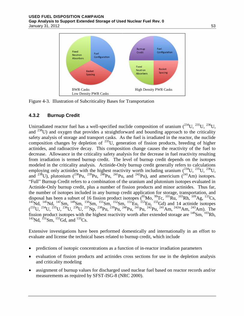
USED FUEL DISPOSITION CAMPAIGN Gap Analysis to Support Extended Storage of Used Nuclear Fuel Rev. 0 January 31, 2012 53
BWR Casks
Low Density PWR Casks
High Density PWR Casks
Figure 4-3. Illustration of Subcriticality Bases for Transportation
4.3.2 Burnup Credit
Unirradiated reactor fuel has a well-specified nuclide composition of uranium (234
U, 235
U, 236
U,
and 238
U) and oxygen that provides a straightforward and bounding approach to the criticality
safety analysis of storage and transport casks. As the fuel is irradiated in the reactor, the nuclide
composition changes by depletion of 235
U, generation of fission products, breeding of higher
actinides, and radioactive decay. This composition change causes the reactivity of the fuel to
decrease. Allowance in the criticality safety analysis for the decrease in fuel reactivity resulting
from irradiation is termed burnup credit. The level of burnup credit depends on the isotopes
modeled in the criticality analysis. Actinide-Only burnup credit generally refers to calculations
employing only actinides with the highest reactivity worth including uranium (234
U, 235
U, 236
U,
and 238
U), plutonium (238
Pu, 239
Pu, 240
Pu, 241
Pu, and 242
Pu), and americium (241
Am) isotopes.
“Full” Burnup Credit refers to a combination of the uranium and plutonium isotopes evaluated in
Actinide-Only burnup credit, plus a number of fission products and minor actinides. Thus far,
the number of isotopes included in any burnup credit application for storage, transportation, and
disposal has been a subset of 16 fission product isotopes (95
Mo, 99
Tc, 101
Ru, 103
Rh, 109
Ag, 133
Cs, 143
Nd, 145
Nd, 147
Sm, 149
Sm, 150
Sm, 151
Sm, 152
Sm, 151
Eu, 153
Eu, 155
Gd) and 14 actinide isotopes
(233
U, 234
U, 235
U, 236
U, 238
U, 237
Np, 238
Pu, 239
Pu, 240
Pu, 241
Pu, 242
Pu, 241
Am, 242m
Am, 243
Am). The
fission product isotopes with the highest reactivity worth after extended storage are 149
Sm, 103
Rh, 143
Nd, 151
Sm, 155
Gd, and 133
Cs.
Extensive investigations have been performed domestically and internationally in an effort to
evaluate and license the technical bases related to burnup credit, which include
predictions of isotopic concentrations as a function of in-reactor irradiation parameters
evaluation of fission products and actinides cross sections for use in the depletion analysis
and criticality modeling
assignment of burnup values for discharged used nuclear fuel based on reactor records and/or
measurements as required by SFST-ISG-8 (NRC 2000).

USED FUEL DISPOSITION CAMPAIGN Gap Analysis to Support Extended Storage of Used Nuclear Fuel Rev. 0
54 January 31, 2012
A technical work plan (Wagner 2007) was developed for the YMP describing a data collection
plan to develop and/or obtain the technical data needed to justify full (actinide and fission
product) burnup credit. Criticality safety cross-cuts all areas of the UFDC, including storage,
transportation, recycling/reprocessing, and disposal, and the data needs are applicable to each
area. The main activities in the technical work plan relate to establishing the specifics of the data
needs, how data are to be used, and implementing programs to procure and/or develop the
needed data. Based on recent developments in modeling and simulation capabilities, and
interactions with the NRC during the YMP licensing process, the technical work plan should be
updated to coordinate and integrate the data collection activities.
4.3.3 Moderator Exclusion
Most storage canisters and some storage casks are designed to serve a dual purpose of storage
and transportation. However, transportation of these systems after a period of storage must be
licensed at the time of transportation to demonstrate compliance with applicable transportation
safety requirements. It is reasonable to assume that the overall safety objectives of radiological
and criticality safety will remain primary transportation requirements, regardless of potential
regulatory evolution. Extended storage would not present significant challenges to meeting
transportation radiological safety requirements as long as the transportation casks are designed
with sufficient shielding and adequate confinement. However, extended storage could present
significant challenges to meeting transportation subcriticality requirements as a result of
potential degradation of fuel cladding, fuel baskets, and neutron poisons. If the geometry of the
fuel or the baskets, including neutron poisons, cannot be demonstrated for normal conditions of
transport and hypothetical accident conditions, moderator exclusion provides an option to
demonstrate subcriticality. Commercial used nuclear fuel, whose enrichment is limited to 5 wt% 235
U, cannot be critical in the absence of moderation (ANSI/ANS-8.1-1998, Table 3).
10 CFR 71.55 (c) states “The Commission may approve exceptions to the requirements of
paragraph (b) of this section if the package incorporates special design features that ensure that
no single packaging error would permit leakage...” However, the NRC staff states in
SECY-07-185 (NRC 2007b) “The requirement that water be assumed within the containment
system is not explicitly tied to the ability of the package to limit water in-leakage under the
regulatory tests and conditions that simulate normal conditions of transport and accident
conditions. Instead, it is a general design requirement that is intended to ensure that no criticality
accident could occur in transportation…”
EPRI (2010c, Section A.1.5.2) states “It is important to note that the requirement for moderator
to be assumed to flood the containment system in the criticality analysis is neither a normal
condition of transport (§71.55(d)) nor a hypothetical accident condition (§71.55(e)) that the
package must be designed to withstand. It is a non-mechanistic assumption required by this
regulation independent of, and in addition to the normal and accident conditions.”
The NRC staff also states in SECY-07-185 (NRC 2007b) “The provisions of 10 CFR 71.55(c)
allow the Commission to approve an exception to the requirement that the package must be
subcritical with water in the containment system. The staff’s long-term practice has been to
consider this exception to be appropriate only for limited shipments and not for general approval

USED FUEL DISPOSITION CAMPAIGN Gap Analysis to Support Extended Storage of Used Nuclear Fuel Rev. 0 January 31, 2012 55
of a design. Using the moderator-exclusion provision of 10 CFR 71.55(c) for the general
approval of a spent fuel cask design has not been considered appropriate in the past, because it
would lead to the routine use of an exception that has important safety implications.”
SECY-07-185 (NRC 2007b) also states “Staff has issued guidance [SFST-ISG-19 (NRC
2003b)], regarding criticality assessments for transportation package designs for commercial
spent fuel, that considers the ability of the cask to prevent water in-leakage under the regulatory
hypothetical-accident conditions (10 CFR 71.55(e))...The guidance was developed to address the
possibility of fuel reconfiguration to a more reactive geometry under accident conditions,
particularly in the case of high-burnup fuel that has unknown cladding strength and ductility.”
It is clear from the above quote that the guidance provided in SFST-ISG-19 is not a general basis
for demonstrating moderator exclusion but applies for only specific conditions to address a very
specific issue. The specific condition is hypothetical accident conditions, and the specific issue
is high burnup fuel. SFST-ISG-19 does not apply to the exemption described in 71.55(c).
Currently, there does not seem to be a general technical or a regulatory path to demonstrating
subcriticality during normal conditions of transport and hypothetical accident conditions after a
period of storage. This issue, which requires further technical research and development as well
as regulatory engagement, is relevant to all used nuclear fuel in dual-purpose dry storage
systems.
The basis for compliance with transportation subcriticality requirements could be a combination
of demonstrating moderator exclusion along with structural integrity of the fuel, baskets, and
neutron poisons, with a validated “full” burnup credit methodology, as illustrated in Figure 4-4.
Figure 4-4. Illustration of Transportation Subcriticality Bases after a Period of Dry Storage
Moderator
Exclusion
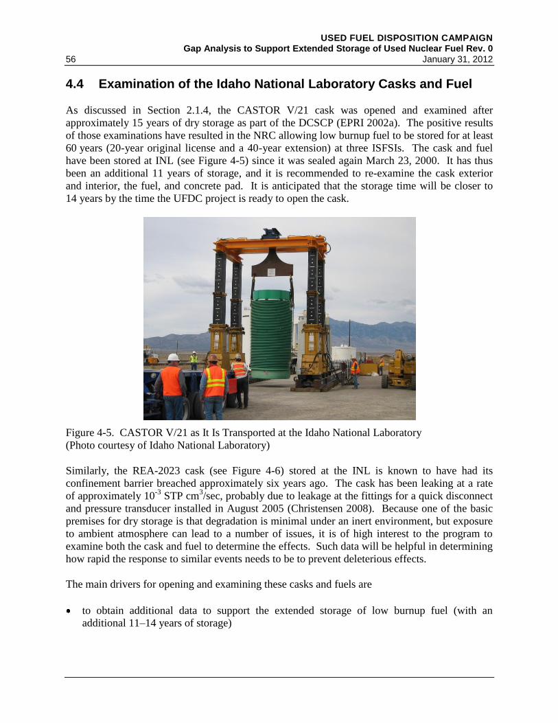
USED FUEL DISPOSITION CAMPAIGN Gap Analysis to Support Extended Storage of Used Nuclear Fuel Rev. 0
56 January 31, 2012
4.4 Examination of the Idaho National Laboratory Casks and Fuel
As discussed in Section 2.1.4, the CASTOR V/21 cask was opened and examined after
approximately 15 years of dry storage as part of the DCSCP (EPRI 2002a). The positive results
of those examinations have resulted in the NRC allowing low burnup fuel to be stored for at least
60 years (20-year original license and a 40-year extension) at three ISFSIs. The cask and fuel
have been stored at INL (see Figure 4-5) since it was sealed again March 23, 2000. It has thus
been an additional 11 years of storage, and it is recommended to re-examine the cask exterior
and interior, the fuel, and concrete pad. It is anticipated that the storage time will be closer to
14 years by the time the UFDC project is ready to open the cask.
Figure 4-5. CASTOR V/21 as It Is Transported at the Idaho National Laboratory
(Photo courtesy of Idaho National Laboratory)
Similarly, the REA-2023 cask (see Figure 4-6) stored at the INL is known to have had its
confinement barrier breached approximately six years ago. The cask has been leaking at a rate
of approximately 10-3
STP cm3/sec, probably due to leakage at the fittings for a quick disconnect
and pressure transducer installed in August 2005 (Christensen 2008). Because one of the basic
premises for dry storage is that degradation is minimal under an inert environment, but exposure
to ambient atmosphere can lead to a number of issues, it is of high interest to the program to
examine both the cask and fuel to determine the effects. Such data will be helpful in determining
how rapid the response to similar events needs to be to prevent deleterious effects.
The main drivers for opening and examining these casks and fuels are
to obtain additional data to support the extended storage of low burnup fuel (with an
additional 11–14 years of storage)
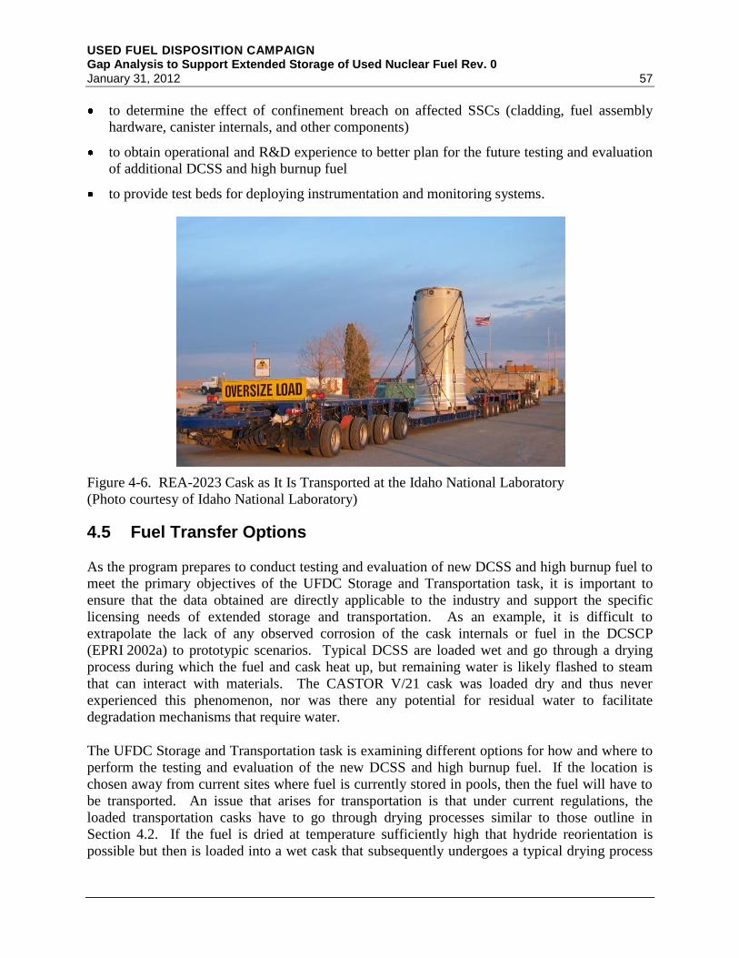
USED FUEL DISPOSITION CAMPAIGN Gap Analysis to Support Extended Storage of Used Nuclear Fuel Rev. 0 January 31, 2012 57
to determine the effect of confinement breach on affected SSCs (cladding, fuel assembly
hardware, canister internals, and other components)
to obtain operational and R&D experience to better plan for the future testing and evaluation
of additional DCSS and high burnup fuel
to provide test beds for deploying instrumentation and monitoring systems.
Figure 4-6. REA-2023 Cask as It Is Transported at the Idaho National Laboratory
(Photo courtesy of Idaho National Laboratory)
4.5 Fuel Transfer Options
As the program prepares to conduct testing and evaluation of new DCSS and high burnup fuel to
meet the primary objectives of the UFDC Storage and Transportation task, it is important to
ensure that the data obtained are directly applicable to the industry and support the specific
licensing needs of extended storage and transportation. As an example, it is difficult to
extrapolate the lack of any observed corrosion of the cask internals or fuel in the DCSCP
(EPRI 2002a) to prototypic scenarios. Typical DCSS are loaded wet and go through a drying
process during which the fuel and cask heat up, but remaining water is likely flashed to steam
that can interact with materials. The CASTOR V/21 cask was loaded dry and thus never
experienced this phenomenon, nor was there any potential for residual water to facilitate
degradation mechanisms that require water.
The UFDC Storage and Transportation task is examining different options for how and where to
perform the testing and evaluation of the new DCSS and high burnup fuel. If the location is
chosen away from current sites where fuel is currently stored in pools, then the fuel will have to
be transported. An issue that arises for transportation is that under current regulations, the
loaded transportation casks have to go through drying processes similar to those outline in
Section 4.2. If the fuel is dried at temperature sufficiently high that hydride reorientation is
possible but then is loaded into a wet cask that subsequently undergoes a typical drying process

USED FUEL DISPOSITION CAMPAIGN Gap Analysis to Support Extended Storage of Used Nuclear Fuel Rev. 0
58 January 31, 2012
as is desired, then the fuel will have been subjected to two drying cycles. This is the likely
scenario for high burnup fuel at short cooling times. Not only is this not prototypic, but it could
result in conclusions that cladding will fail when that may not be the case for typical fuels that
are dried only once.
Similarly, if dried fuel is then rewetted, there is the potential for rapid cooldown and thermal
shock if the process is not carefully controlled. It is also possible that the layers of crud on the
fuel may spall (EPRI 1998). While the possible contamination is an issue, more important is the
fact that the spallation of crud or oxide layers could affect local clad properties in the tests and
give non-prototypic results. Finally, if hot fuel is cooled rapidly (pool temperatures are typically
about 30°C), it is unknown if that will cause additional hydride precipitation, and again skew
results when those fuels are analyzed.
It is thus important to perform a detailed analysis to evaluate the data impacts associated with
two drying cycles, rewetting dried fuel, quenching of phases, crud or oxide spallation, and other
phenomena that may occur under the various transfer scenarios considered. This analysis will
then help determine the pros and cons of the different scenarios and allow the UFDC to make
informed decisions on the preferred methods for transfer of fuel. It should be stressed again that
these tests are key to the relicensing of high burnup fuel currently, or soon to be emplaced, in dry
storage. Fiscal year 2012 efforts to evaluate which degradation mechanisms are affected and to
evaluate alternatives to wet transportation are planned.
Once the testing and evaluation of the new DCSS with high burnup fuel are initiated, it is
preferred, for the reasons outlined above, to keep the fuel and DCSS dry. Keeping the system
dry requires a means to open the DCSS, remove fuel assemblies to allow examination of the fuel
and DCSS internals, remove selected fuel pins for detailed characterization, return the assemblies
and reseal the DCSS, and return the DCSS to the storage pad. For the DCSCP, this was done in
the TAN facility at INL. However, TAN has been decommissioned. To meet these objectives,
the UFDC Storage and Transportation task is re-examining the use of a Dry Transfer System as
was started under an Office of Civilian Radioactive Waste Management program (e.g.,
EPRI 1995, 1999). Similarly, deployable dry transfer systems capable of transferring canisters
from dry storage overpacks to transportation overpacks need to be examined, especially for the
“ISFSI Only” sites where no transfer infrastructure exists.
4.6 Monitoring
In the nuclear industry, monitoring generally refers to a continuous activity, whereas inspection
is a periodic activity that may or may not involve 100% of the SSCs to be inspected. It is
strongly desired to develop capabilities to allow monitoring and inspection using non-destructive
techniques and that do not call for penetrating confinement barriers. The overall need for
advanced monitoring and instrumentation capabilities for utilization in the R&D program and in
the long-term engineering-scale demonstration is considered a High priority, but individual needs
identified may be of Low, Medium, or High priority. In many cases, the need for monitoring
capability will depend on the outcome of closing data gaps identified in Section 5.
USED FUEL DISPOSITION CAMPAIGN Gap Analysis to Support Extended Storage of Used Nuclear Fuel Rev. 0 January 31, 2012 59
4.6.1 Introduction
10 CFR 72.122 requires that “Storage confinement systems must have the capability for
continuous monitoring in a manner such that the licensee will be able to determine when
corrective action needs to be taken to maintain safe storage conditions.” 10 CFR 72.128 requires
“a capability to test and monitor components important to safety.” Section IV.4 of SFST-ISG-5
(NRC 1998b) states “The [NRC] staff has accepted routine surveillance programs and active
instrumentation to meet the continuous monitoring requirements.” SFST-ISG-5 also states
“NRC staff has found that casks closed entirely by welding do not require monitoring. However,
for casks with bolted closures, the staff has found that a seal monitoring system has been needed
in order to adequately demonstrate that seals can function and maintain a helium atmosphere for
the 20-year license period, and “The staff has accepted monitoring systems as not important to
safety… Although [their] function is to monitor confinement seal integrity, failure of the
monitoring system alone does not result in a gross release of radioactive material.”
Continued efficacy or acceptable performance of various components within the DCSSs,
including fuel, cladding, baskets, and neutron poisons, is currently demonstrated through
analysis for relatively short-term (i.e., 60-year) storage license periods. For extended storage,
projection of continued efficacy or acceptable performance of these components may not be
possible without collecting data to validate the models developed using data from short-term
tests. To collect the potentially needed data, various monitoring systems need to be developed.
The purpose of the monitoring systems is not only to detect SSC failures or precursors to those
failures but also to evaluate materials property changes that can be correlated to their structural
performance.
Conditions or degradation mechanisms that could lead to changes in material properties are
summarized in Section 4.6.2 for concrete structures, metallic components, and other components
including fuel and elastomeric gaskets. The degradation mechanisms that result in specific
changes in material and environmental parameters are potential targets for sensing and
instrumentation needs. Several candidate sensing methods are discussed in Section 4.6.3. The
discussion in Section 4.6.3 includes a description of candidate methods and techniques for
sensing approaches for mechanical properties and environmental conditions as well as enabling
technologies facilitating power sources and signal transmission. Finally, Section 4.6.4
summarizes the information and identifies potential R&D needs for long-term monitoring of dry
storage systems components.
4.6.2 Relevant Aging/Degradation Mechanisms
The symptoms associated with degradation mechanisms of concern to extended storage of used
nuclear fuel in dry storage systems are summarized in this section for all SSCs—concrete
structures, metallic components, and other components, including fuel and elastomeric gaskets.
4.6.2.1 Concrete Structures
Degradation mechanisms deemed relevant to concrete structures include corrosion of reinforcing
steel, chloride attack, alkali–silica reactions, sulfate attack, carbonation, freeze–thaw, dry-out,
USED FUEL DISPOSITION CAMPAIGN Gap Analysis to Support Extended Storage of Used Nuclear Fuel Rev. 0
60 January 31, 2012
shrinkage, creep, thermal fatigue, aggregate growth, decomposition of water, and leaching of
calcium. In many cases, deterioration can be accelerated by the simultaneous occurrence of
multiple degradation mechanisms. For instance, the corrosion of reinforcing steel is readily
accelerated in the presence of aggressive chloride attack, carbonation, or cracks formed by other
damage mechanisms. Concrete condition may therefore be assessed indirectly by monitoring
environmental factors relevant to concrete deterioration or by direct measurement of physical
changes in the structure
In most cases, degradation of concrete results in both changes in strength and some visible
expression of damage on the surface. For instance, corrosion of embedded reinforcing steel can
lead to cracking and spalling. In addition, corrosion can result in the debonding of concrete from
the steel members, resulting in a reduction of strength (Shah and Hookham 1998). The corrosion
process is often accompanied by several environmental indicators including moisture level, pH,
and concentrations of several chemical species including chlorides, oxygen, and hydroxyl ions.
A combination of these indicators accompanies most other forms of concrete degradation.
4.6.2.2 Metallic Components
The container and internal components consist mostly of metallic components, with the
exception of the fuel and elastomeric seals. Metal components internal to the container include
the cladding, grid spacers and fuel baskets, and neutron poisons.
Corrosion is a concern for the weld regions and base metal of the container as well as the grid
spacer/fuel basket hardware and the neutron poisons. Corrosion can result in dimensional
changes (thinning) and produce visible signs of damage in the form of discoloration or staining
on the surface. In some cases, corrosion can also lead to the formation of cracks (stress-
corrosion cracking). The threat of corrosion in marine environments is heightened due to the
harsh environmental conditions.
Base metal and weld regions of the container and cladding are considered susceptible to
oxidation. Oxidation of metal components can be expressed as visible discoloration on the
surface of the oxidized component. The oxide layer has a definite thickness that can be
perceived as a dimensional change of the component with precise instrumentation. Isothermal
growth can lead to the buildup of significant stresses within the oxide layer. This stress is
relieved through detectable events such as cracking and spalling of the oxide layer (Walter et al.
1993).
Creep and thermal fatigue have been identified as degradation concerns for all internal
components except the fuel. Creep is expressed primarily through dimensional changes to the
components, while both creep and thermal fatigue can result in changes to the bulk properties of
the material (mechanical/electrical). Severe fatigue may also lead to cracking.
Additional aging concerns specific to the cladding include hydrogen effects, annealing, thermal
fatigue, and thermal/radiation embrittlement. These mechanisms may result in changes to the
bulk electrical and mechanical properties of the material. In some circumstances, hydride
formation/reorientation and hydrogen embrittlement may lead to cracking.
USED FUEL DISPOSITION CAMPAIGN Gap Analysis to Support Extended Storage of Used Nuclear Fuel Rev. 0 January 31, 2012 61
4.6.2.3 Fuel and Elastomeric Gaskets
Swelling, pellet cracking and fragmentation, and oxidation are the primary degradation concerns
of the fuel. These mechanisms could exhibit changes to component dimensions and bulk
material properties. In the case of fragmentation, the creation and release of radioactive particles
and gases is also of concern. The release of gases from damaged fuel pellets could alter the
pressure and gas composition internal to the fuel pin. Oxidation could lead to swelling of the
fuel pellet, perceived as a dimensional change.
A breach in confinement could result from the relaxation or corrosion of the closure bolts or
failure of the metallic gaskets. Relaxation of closure bolts would result from a change in the
length of the bolts or gross deformation including cracking. The condition of the seal integrity
would be evident due to the presence or lack of gas leaks around the seal perimeter. Indications
of seal integrity prior to gas leaking could be expressed through the amount of force coupling the
lid and canister components to the seals. Elastomeric seals could potentially experience
embrittlement due to exposure to thermal or radiation stresses. Embrittlement of elastomeric
materials could be expressed through changes to mechanical properties including increased
hardness and a reduction in tensile strength. It may also result in discoloration (Toman and
Gazdzinski 1996).
4.6.2.4 Environmental Symptoms
The monitoring of several environmental quantities can also be used to indicate degradation or
failure of components in dry storage systems. As indicated earlier, the monitoring of pH or
moisture levels can potentially be used as a proxy for detecting corrosion or other degradation
mechanisms in both concrete and metallic components. Environmental monitoring is
particularly well-suited for detecting degradation in cask internals. Detection of 85
Kr in the
storage cask internal atmosphere is a clear indicator of cladding breach in the stored fuel. If
measuring the composition on a periodic basis, the precise moment of failure will not be known,
but the period in which the release occurred can be identified. Indication of failure, but not
extent of damage, may be determined from the fuel burnup and time out of reactor and the
concentration of 85
Kr seen in the cask atmosphere.
Other key environmental quantities include relative humidity, temperature, oxygen levels, and
pressure. Relative humidity inside the cask is a stressor with a significant impact on the potential
for corrosion. The corrosion process itself leads to the generation of hydrogen gas, which can be
detected in the cask headspace. Temperature monitoring can serve as an important indicator of
cask internal degradation. Abnormalities in the conduction/convection of heat within the cask
internal environment may result from degradation of the cask internals, including loss of inert
atmosphere or oxidation of metal components. Such abnormalities can be expressed by
anomalous temperature readings. Pressure monitoring provides a global indication of boundary
integrity. Loss of cover gas or inert atmosphere due to seal degradation can result in a
measurable change in pressure. Finally, previous studies on small casks (Winston 2007) in dry
storage since 1990 (Einziger et al. 2003) indicate that the presence of oxygen inside the
confinement barrier (in what should be an inert, dry internal environment) will lead to issues
USED FUEL DISPOSITION CAMPAIGN Gap Analysis to Support Extended Storage of Used Nuclear Fuel Rev. 0
62 January 31, 2012
with oxidation of cladding and swelling of the fuel, potentially leading to failure of the cladding
and/or fuel.
4.6.3 Sensing Systems
Several technologies exist for detecting degradation in the materials of concern for the extended
storage of used nuclear fuel in dry storage systems. The technical maturity of potential
techniques can vary considerably, from commercial off-the-shelf technologies that require only
minor or no adaptations before use in dry storage systems monitoring applications to
technologies that will require considerable laboratory development before their field deployment
is feasible. In the following paragraphs, discussions of the potential monitoring technologies are
provided.
4.6.3.1 Assessing Mechanical Integrity
A range of technologies are available for assessing mechanical integrity of concrete, containers
and internals. Changes in the linear and nonlinear elastic properties of concrete due to
degradation such as debonding, corrosion of rebar, cracking and spalling form the basis of
several acoustic measurement techniques, including impact echo, ultrasonic pulse velocity and
attenuation, guided wave and nonlinear elastic wave spectroscopy (NEWS). Degradation
resulting in a change in concrete strength or uniformity may be monitored using impact echo
techniques (using a simple tool such as the Schmidt hammer) and measurements of ultrasonic
pulse velocity and attenuation. The ultrasonic measurements (both linear and nonlinear) are also
sensitive to concrete expansion and cracking caused by alkali–silica reactions (Shah and
Hookham 1998). However, these measurements can be impacted by the presence of reinforcing
steel and the type and amount of aggregate contained in the concrete mixture (Malhotra and
Carino 2004).
The acoustic/ultrasonic techniques described above are active techniques, requiring the
application of an external excitation. Passive acoustic methods such as acoustic emission testing
(AET) and acoustic daylight imaging (ADI) are also sensitive to degradation. AET is sensitive
to only the dynamic nature of flaw formation and growth. ADI, or ambient noise correlation, is
used for continuous monitoring of a structure through the measurement of ambient vibrational
noise in a system (Claerbout 2000; Snieder and Wapenaar 2010). However, the use of AET and
ADI for monitoring concrete degradation is in its infancy.
Several approaches sensitive to the electrical properties of concrete have possible utility for
degradation detection. Electrical potential drop techniques and their variants have been used
successfully for detecting localized cracking as well as corrosion, debonding, and voids. The
half-cell potential method is a passive variant of the potential drop methods, where
measurements are made of the electric potential on the surface of the concrete relative to the
potential of the reinforcing steel. Strong electrical potential gradients indicate sites where
localized anodes have formed and thus provide some indication of the susceptibility of the
reinforcing steel to corrosion (Malhotra and Carino 2004). The linear polarization resistance of
concrete is inversely related to the corrosion current density and can provide an estimate of the
instantaneous rate of corrosion (Malhotra and Carino 2004). Most of these measurements are at

USED FUEL DISPOSITION CAMPAIGN Gap Analysis to Support Extended Storage of Used Nuclear Fuel Rev. 0 January 31, 2012 63
low frequencies (from zero to several hundreds of kilohertz). Electromagnetic measurements at
higher frequencies (radio frequency/microwave frequencies) can be used to determine the
presence of interfaces (such as rebar). The measurement is impacted by changes in the
electromagnetic properties and therefore can be used to also determine changes in dielectric
properties due to degradation. Thus, radio frequency/microwave measurements have been used
to determine moisture content/presence in concrete, rebar corrosion, and chloride
migration/concentration in concrete (Case et al. 2004; Nadakuduti et al. 2006).
In metals, degradation (such as cracking, corrosion, or hydride formation) also results in changes
in the elastic, electric, and magnetic properties. Linear and nonlinear acoustic techniques have
been used successfully for crack and corrosion detection in a variety of metals. Conventional
linear acoustic measurements are commonly used in periodic in-service volumetric inspection of
metallic nuclear power plant components (ASME 2001).
Advanced acoustic measurement techniques such as guided wave testing (GUT), resonance
ultrasound inspection (RI), and NEWS are being investigated for inspection and monitoring of
metals as well. For instance, guided waves have been used to inspect baffle-former bolts in
PWR pressure vessel assemblies (IAEA 2007). GUT is being actively studied as a tool to detect
discontinuities and wall thinning of fuel rod cladding (Kwun et al. 2009) and to inspect buried
and underground piping systems at nuclear power plants (EPRI 2008). GUT concepts have also
been devised for monitoring steam generator (Rose et al. 1994) and heat exchanger tubes
(Vinogradov and Kidd 2006). RI has been applied to determine either the elastic properties of
the material (assuming known geometry) or dimensional changes (assuming known elastic
constants), such as pipe thickness. Nonlinear nondestructive evaluation methods such as NEWS
provide order(s) of magnitude increased sensitivity to the detection (Nagy 1998), localization,
and imaging (Kazakov et al. 2002; Ulrich et al. 2008) of mechanical defects such as cracks, and
have been used to monitor progressive damage in metals and concrete.
Passive acoustic techniques are also applicable to monitoring damage in metals. The efficacy of
AET monitoring with waveguides was demonstrated through field tests conducted on full-scale
reactor vessels at the Tennessee Valley Authority (TVA) Watts Bar Unit 1 reactor (Hutton et al
1984) and the Exelon Limerick Unit 1 reactor (Hutton et al. 1993). Laboratory investigations
have shown that AET is sensitive to damage associated with fatigue (Harris and Dunegan 1974;
Moorthy 1994), corrosion and stress-corrosion cracking (Lenain and Proust 2005; Shaikh 2007),
and creep (Clark 1982). In addition, AET can detect the cracking and spalling of oxide scales
(Walter et al. 1993) and can be used for leak monitoring applications (Kupperman et al. 2004).
Measurement methods sensitive to electrical and magnetic methods are particularly applicable to
detecting degradation in metals. Eddy current testing (ET) is a relatively mature technique that is
used for detecting cracking in conducting materials. ET is limited to the inspection of materials
with “sufficient” electrical conductivity (mostly metals, although materials such as carbon fiber
composites have also been inspected using ET). Its depth of penetration (or skin depth) exhibits
an inverse relationship with respect to frequency, electrical conductivity, and magnetic
permeability. ET can therefore perform volumetric inspections of relatively thin metallic
components, such as the walls of steam generator tubing for which mature ET technology exists
USED FUEL DISPOSITION CAMPAIGN Gap Analysis to Support Extended Storage of Used Nuclear Fuel Rev. 0
64 January 31, 2012
(IAEA 1997; EPRI 1998). ET is also used to inspect the integrity of fuel cladding and measure
oxide thickness (McKinnon and Cunningham 2003; Van Nieuwenhove and Solstad 2010).
Multiple approaches (referred to as potential drop methods) exist that use direct injection of
current into the specimen under test while the potential difference between pairs of electrodes is
monitored. These techniques are sensitive to changes in electrical conductivity. Current leads
are attached to a specimen such that the flow of electrical current is impeded by a growing crack.
The voltage across the crack is monitored and is empirically correlated to crack length. This
method has been applied to assess the response of materials to PWR and BWR environments
using common test specimen geometries (Toloczko and Bruemmer 2009). Efforts to develop an
on-line direct current potential drop monitoring system to assess fuel cladding integrity are under
way at the Halden Reactor Project. In this system, current is injected through plugs on both ends
of the fuel rod. It is estimated that this system can measure oxide thickness with an accuracy of
2 µm (Bennett and Karlsen 2010). Several corrosion monitoring techniques are based on
measurements in resistance changes as a result of metal loss due to corrosion. The electrical
resistance probe simply consists of a thin metallic strip or wire, the resistance of which is
monitored as material corrodes away. This technique does not directly sample the component of
interest but can potentially provide a continuous in situ indication of the probability of corrosion.
Several electrochemical techniques are also being explored for on-line monitoring of fuel
cladding corrosion, but these require the presence of a conducting electrolyte (Bosch and
Bogaerts 2010).
A range of magnetic measurements are also available for inspecting ferromagnetic materials.
Magnetic flux leakage methods rely on measurements of leakage flux due to the presence of
flaws in materials that are magnetized (usually temporarily). These techniques are generally
mature and used commonly for periodic inspection.
Conventional acoustic and electromagnetic techniques are relatively mature from the perspective
of detecting degradation. However, they have been used predominantly for periodic inspections.
Further, these methods (especially low-frequency electromagnetic techniques such as eddy
currents and potential drop methods) are generally spatially localized. Considerable effort in
sensor and instrumentation design for operation in adverse environments and automated data
processing is needed to move these technologies into the online monitoring realm. It is also
likely that, unless a priori knowledge can be utilized to position such sensors at key locations of
high stress, the necessary number of sensors to monitor a complete structure will be large.
Advanced active acoustic techniques (such as guided waves, RI, and NEWS) and
electromagnetic methods (such as Barkhausen noise measurement, and RF/microwave/terahertz
measurement methods) have the potential for online monitoring of structural components
(concrete and/or metals) using relatively few sensors. However, considerable R&D is needed to
address key questions including the sensitivity and detection probabilities of these methods to the
expected degradation mechanisms identified earlier. Passive acoustic techniques such as AET
and ADI are ideally suited for continuous monitoring. However, these techniques have seen
limited application and, as with the advanced acoustic techniques, require additional R&D.

USED FUEL DISPOSITION CAMPAIGN Gap Analysis to Support Extended Storage of Used Nuclear Fuel Rev. 0 January 31, 2012 65
Several other nondestructive approaches to monitoring degradation and strength of concrete and
metals are also available. These range from radiographic techniques to remote visual inspection
and thermal imaging methods. Other methods that are minimally invasive include hardness tests
and dye penetrant tests (particularly for crack detection in metals). These techniques are usually
better suited for periodic inspection instead of online monitoring, and considerable R&D effort is
needed if these are to be transitioned to continuous monitoring.
A summary of possible sensing technologies matched to degradation expressions is presented in
Table 4-1 for fuel cladding and the container. These were the only metallic SSCs with
degradation mechanisms labeled as Medium and High priority (see Tables 5-2 and 5-7 in this
document). In Table 4-1, damage mechanisms corresponding to the appropriate degradation
expressions are provided in parentheses.
Table 4-1. Possible Technologies Sensitive to Medium- and High-Priority Degradation
Phenomena for the Fuel Cladding and Container
4.6.3.2 Assessing Environmental Integrity
Measurement of 85
Kr in a laboratory setting is commonly done via gamma ray spectrometry. A
gas sample is positioned above a high-purity germanium detector in a known geometry. For cask
monitoring purposes, samples can be bled from the vent or purge port and can be sent to a
laboratory for analysis in minimum background controlled conditions. This monitoring practice
is employed on a 2- or 5-year period for the commercial fuel in storage in casks at the INL.
Cracking, Pitting,
Spalling
(corrosion,
oxidation,(a)
H2 effects)
Dimensional
Changes
(corrosion,
oxidation,
creep)
Discoloration/
Staining
(corrosion,
oxidation)
Changes to Bulk
Material
Properties (H2
effects, radiation
annealing, creep)
Conventional ultrasonic X X --- X
Guided ultrasonic wave X X --- ???
Resonance inspection X X --- X
NEWS X --- --- X
Acoustic emission X --- --- ---
ADI X X --- X
Eddy current X X --- X
Electrical potential drop X X --- X
Visual X X X ---
(a) Stresses build up in oxide films as they grow in thickness, potentially leading to cracking and spalling of the
oxide film.
X = NDE technique exhibits some level of sensitivity to degradation expression.
--- = NDE technique is not applicable to the observation of the degradation expression.
??? = Applicability of NDE technique to observing degradation expression is unknown.

USED FUEL DISPOSITION CAMPAIGN Gap Analysis to Support Extended Storage of Used Nuclear Fuel Rev. 0
66 January 31, 2012
The headspace of the storage package can be readily monitored using a commercially available
pressure transducer. These transducers readily convert pressure force to analog signals
(4–20 mA typically) or digital signals. Pressure transducer access can be accommodated through
the vent/purge port.
Thermocouples and resistance temperature detectors are commonly used devices that convert
temperature to an analog electrical voltage or resistance signal. Thermocouples are readily
available that work in high temperature and high radiation conditions. Temperature
measurement including axial profile and rod with highest temperature could be obtained with a
basket design that incorporates thermocouples at the desired radial and axial locations. Infrared
and fiber optic technologies also exist for temperature measurements, but their effectiveness in
DCSSs is limited due to lack of line-of-sight access for infrared detectors and the susceptibility
of fiber optics to damage from gamma radiation exposure.
The potential for corrosion can be monitored with humidity sensors. Hydrogen sensors can be
deployed to detect active corrosion and oxygen sensors can be deployed to detect the potential
for oxidation. Survivability of these sensors within the container has not been determined.
4.6.3.3 Enabling Technologies
The development of enabling technologies is required to meet the following aspects of dry
storage systems monitoring: 1) sensor power transmission/generation, 2) data transmission
3) sensor compatibility, and 4) data management. Confinement boundaries of dry storage
systems are designed to act as a resilient barrier to the exchange of solids, fluids, and radiation.
Therefore, maintaining the integrity of this barrier while assessing DCSS internals is inherently
difficult. Hardwire access could be provided by the addition of access ports or modification of
existing purge and vent ports. The Nuclear Pacific 125B casks that were fabricated for shipping
of the Three Mile Island (TMI) Unit 2 debris are currently in service at the INL as storage
packages. The 125B design incorporates a drain path that could be adapted for use in direct wire
data and power transmission. However, the penetrations required for hardwire access present
opportunities for confinement breach and should be avoided, assuming alternative methods are
available to effectively transmit power and data. The following paragraphs discuss technologies
that could aid in providing power to the internal confinement boundary and transmitting data
signals through the DCSS wall.
Power
Beyond hard-wiring sensors to external power sources, options for providing power to sensors
inside DCSS confinement boundaries include batteries and energy-harvesting devices that can
convert the available thermal or radiation energy into electricity.
Thermoelectric generator modules can generate electricity in the presence of a thermal gradient.
Thermal power available inside a storage cask that could potentially be used for internal
generation is variable, depending on the initial burnup and cooling time and the type of fuel and
number of assemblies stored in each cask. For casks loaded with a nominal 12 MTU, the range
is approximately 30 kW per cask for a 5-year-cooled fuel with a burnup of 45 GWd/MTU and
USED FUEL DISPOSITION CAMPAIGN Gap Analysis to Support Extended Storage of Used Nuclear Fuel Rev. 0 January 31, 2012 67
approximately 2.5 kW per cask for a 110-year-cooled fuel with burnup of 25 GWd/MTU. The
50-year values are approximately 5 kW and 9 kW per cask for the 25- and 45-GWd/MTU
burnups (NRC 1999).
Photovoltaic devices based on CdZnTe, PbTe, SiC, polymeric composites, and other materials
may also be developed to potentially harvest the gamma ray energy inside the canister to power
sensors and transmission gear. Gamma radiation within the package exceeds 3000 rad/hr even
with a fuel that is more than 30 years out of reactor (Winston 2007). Other types of possible
radiation energy harvesting devices include betavoltaic batteries and radioisotope thermoelectric
generators.
Data Transmission
The container consists of a metal wall with several inches of thickness and is impenetrable to
propagating electromagnetic energy unless an access port is provided for the energy exchange.
A sealed, shielded penetration path could be incorporated into the lid system using the existing
vent and purge penetrations or a dedicated new location. Radio communication is
straightforward, and commercially available components can be applied. To eliminate the need
for shielding, the entire functional electronics package could be mounted external to the
container. Data transmission will be by IEEE 802.11 protocol (in use at the INL CPP2707 cask
pad for temperature and pressure data transmission) or conventional radio transmission.
It may be feasible to develop devices based on near-field magnetic induction to communicate
between the inside and outside of a canister. A transmission coil and receiving coil, tightly
coupled, may allow modulated magnetic field containing the sensor signal information to
penetrate through the canister wall and be captured on the outside. For practical dry storage
systems monitoring applications, the communication should be bidirectional.
Ultrasonic communication devices could be employed to transmit internal cask signals through
DCSS confinement barriers. These devices have been proposed for transmitting signals through
thick sections of steel. Efforts to improve efficiency and power transmission capacity are
ongoing (Massie 2008; Murphy 2006).
Sensor Compatibility
Initially, the cask environment will be harsh and challenge the use of many types of sensors due
to high temperature and/or gamma radiation stressors. The development of appropriate sensors
that can tolerate initial cask loading temperatures and radiation levels with minimal functional
degradation, taking into account drift and calibration issues, is necessary. This can be addressed
either through the design or modification of materials to increase resistance to the effects of
radiation and temperature or through limiting exposure of the sensor to the harsh environment
through standoff or remote monitoring techniques.

USED FUEL DISPOSITION CAMPAIGN Gap Analysis to Support Extended Storage of Used Nuclear Fuel Rev. 0
68 January 31, 2012
Data Management
The potential longevity and number of dry storage systems employed for storage of used nuclear
fuel necessitate a deliberate consideration of long-term data management approaches. Necessary
considerations include approaches to ensure archival of data over multiple centuries and data
fusion methods to facilitate decision making based on multiple streams of information. Data
fusion for DSCC diagnostics and prognostics could potentially minimize worker dose
accumulations in addition to automating (to the extent possible) decision making regarding the
presence of degradation.
4.6.4 R&D Priorities for Monitoring
The R&D priorities for monitoring systems for R&D and the engineering-scale demonstration
are established based on several factors including demonstrating compliance with storage safety
requirements, maintaining structural integrity of SSCs, and preventing or limiting significant
material property changes. Monitoring R&D activities will be implemented in a phased
approach starting with a state-of-the-art review and laboratory testing followed by technology
development.
One of the goals for monitoring and instrumentation development is to reduce the number of
times that a cask needs to be opened and examined as part of the proposed engineering-scale
demonstration for high burnup fuel being developed by the UFDC.
4.6.4.1 Confinement Barrier Monitoring: High
Early detection of canister weld and metallic confinement seal degradation is considered of high
priority since a breach in confinement directly violates safety requirements and will have a
significant influence on the extent of degradation of internal SSCs, including fuel cladding,
baskets, and neutron poisons. R&D activities for weld monitoring or inspection should focus on
identifying techniques capable of detecting stress corrosion cracking at early stages or precursors
to stress corrosion cracking. R&D activities for detecting early seal failure should focus on
techniques sensitive to small leaks and techniques capable of sensing the relaxation of sealing
hardware.
4.6.4.2 Environmental Monitoring: High
Monitoring of the internal cask environment is a high priority. The inert He cover gas prevents
corrosion of internal components and the stability of such an environment is an indicator of the
integrity of the confinement barrier. Further, the internal cask environment will be affected by
breaches in fuel rod cladding. Some sensors for environmental monitoring of the internal cask
environment include pressure, temperature, humidity or moisture, 85
Kr sensors, and several gas
composition sensors (He, O2, N2, and H2). R&D activities should focus on optimal deployment
of such sensors for best detection of fuel or canister breaches. Deployment of sensors inside of
the cask will also require means of powering sensors and transferring data without compromising
the integrity of the confinement boundary. Although environmental monitoring is sensitive only

USED FUEL DISPOSITION CAMPAIGN Gap Analysis to Support Extended Storage of Used Nuclear Fuel Rev. 0 January 31, 2012 69
to gross failures of fuel and canister boundaries, R&D activities in this area are likely to have a
significant near-term impact and would play an important role in reducing the number of
intrusive and expensive examinations of the cask(s) that are part of the engineering-scale
demonstration. Monitoring of the external environment is also of high importance, but in most
cases adequate technology already exists.
4.6.4.3 Corrosion Detection of Steel Embedded in Concrete: Medium
Monitoring the corrosion of reinforcing steel in concrete structures is considered a medium
priority. The consequence of concrete failure can vary depending on the mitigating actions
available, and typically with rebar corrosion, by the time the damage is visible, it is so extensive
that corrective actions are, at a minimum, very costly if even possible. R&D activities should
focus on early detection of corrosion of reinforcing steel. Timely detection of corrosion of
reinforcing steel allows for corrective measures to prevent failure of the structure.
4.6.4.4 Mechanical Integrity of Internal SSCs: Low
Direct monitoring of the mechanical integrity of internal cask components is desirable.
However, a better understanding of long-term integrity issues is needed to provide proper
guidance and direction to these activities. As additional data on the degradation mechanisms for
the SSCs identified in Section 5 are obtained, the importance of development of specific
monitoring capabilities will be reevaluated.
Recommended activities are organized into three themes: 1) direct assessments of integrity,
2) indirect assessments of integrity, and 3) enabling technologies. Some cross-cutting issues that
also need to be addressed include the required temporal resolution of measurements for
continuous, in situ monitoring scenarios as well as data management strategies for managing
large volumes of diverse data in a manner that minimizes decision burdens and worker dose
exposures. Generally, the path forward for each R&D theme is a phased approach, with a state-
of-the-art review, laboratory testing, and technology development phases.

USED FUEL DISPOSITION CAMPAIGN Gap Analysis to Support Extended Storage of Used Nuclear Fuel Rev. 0
70 January 31, 2012

USED FUEL DISPOSITION CAMPAIGN Gap Analysis to Support Extended Storage of Used Nuclear Fuel Rev. 0 January 31, 2012 71
5. GAP ANALYSES
The methodology discussed in Section 3 is applied in this section to nine of the ten SSCs
(monitoring was covered in Section 4.6). The organization for each gap analysis is as follows:
1. Introduction. This subsection describes the SSC and its use in various dry storage systems as
well as its design variants and material(s) of construction.
2. Analysis of Safety Functions. This subsection provides a brief analysis of the degradation of
the SSC and the associated impacts on the safety functional areas. This subsection concludes
with a ranking (Low, Medium, or High) of how important the SSC is to providing or
maintaining safety functions and thus its importance to licensing.
3. Discussion of Selected Issues. These subsections examine the various degradation
mechanisms that apply to the SSC. A summary of the literature review for each degradation
mechanism is provided. Based upon the importance of the SSC to licensing, the potential
effects of extended storage or high burnup on the degradation mechanism, and a combination
of the data needs, regulatory considerations, likelihood of occurrence, the consequence of
degradation, the means to remediate the degradation, and the impact of degradation on cost,
operations, and future waste management strategies, an R&D priority (Low, Medium, or
High) is assigned. The R&D priority cannot be higher than the ranking assigned for
importance to licensing as obviously an SSC ranked of Low importance to licensing does not
require a Medium or High priority for R&D. However, an SSC can be of High importance to
licensing, but the R&D needs can be lower depending on the criteria above.
4. Summary Table. A table showing all the degradation mechanisms for the SSC, grouped by
stressor type (see Section 3.2), is presented. The table identifies whether the degradation
mechanism is influenced by extended storage or higher burnup, whether additional data are
needed, and the R&D priority. In almost all cases, additional data are needed in that the data
on many of the newer materials or designs and how mechanisms are impacted by longer
times or higher burnup either do not exist or are not publicly available. The importance for
more data, however, is prioritized using the methodology presented here.
5. Approach to Closing Data Gaps. This subsection briefly discusses how each of the Medium
or High priority gaps may be addressed. The discussion is meant to be a high-level approach
of whether experimental work, analyses, modeling and simulation, detailed aging
management plans (AMPs), or a combination of these approaches are needed. Detailed
discussions of specific means for addressing the data gaps will be provided in a report to be
produced in fiscal year 2012. It is envisioned that the gaps will be closed by obtaining data
through separate effects tests, modeling and simulation, small-scale tests, and in-service
inspections. The predictive models developed through this effort will be validated through a
long-term engineering-scale demonstration of high burnup fuel in full-scale casks/canisters.
The UFDC Storage and Transportation staff is actively pursuing collaborations to help address
the data gaps in a timely and cost effective manner. These collaborations include the various
university groups working on these issues as part of DOE’s Nuclear Energy University Program
(NEUP). The UFDC is also an active participant in the EPRI-led Extended Storage

USED FUEL DISPOSITION CAMPAIGN Gap Analysis to Support Extended Storage of Used Nuclear Fuel Rev. 0
72 January 31, 2012
Collaboration Program (ESCP). The ESCP was formed in November 2009 and consists of
industry, regulators, and government labs bringing together a wide range of perspectives and
technical expertise to address objectives similar to those of the Storage and Transportation task
identified in Section 1. The ESCP also includes an International Subcommittee chaired by the
Storage and Transportation manager. The goals of this subcommittee are to identify the gap
analyses in each of the participating countries (currently the United States, the United Kingdom,
Spain, Germany, Hungary, Japan, and South Korea), identify commonalities, and collaborate to
address these data gaps.
5.1 Fuel
5.1.1 Introduction
A variety of fuels, including oxides, metals, carbides, and nitrides, have been used in nuclear
reactors worldwide. The analyses in this report are limited to zircaloy-cladded UO2 UNF from
domestic commercial LWRs (5 wt% 235
U maximum enrichment). Mixed oxide (MOX) fuel
consisting of a mixture of plutonium and uranium oxides may be used in the near future. The
chemical, mechanical, and physical properties of MOX can be markedly different from UO2 and
would require a separate analysis.
Typical UO2 fuels undergo significant changes during reactor operations. The fission process
generates a myriad of fission products, many of which are soluble in the UO2 matrix. Those
elements that are not soluble in the matrix tend to either diffuse out of the grains to the grain
boundaries and eventually out of the fuel pellet to the fuel–clad gap or they form separate
metallic or oxide phases within the fuel. As a general rule, the quantity of fission gases, such as
Xe and Kr, released from the fuel pellet increases with increasing burnup. In reality, the duty
cycle, which is a combination of parameters such as the operating power level, temperature, and
other factors, has a larger direct effect than burnup. Actinides such a Pu, Am, and Cm are also
generated in the fuel by neutron capture reactions. The quantity of both fission products and
higher actinides increases roughly linearly with burnup.
Other changes that occur with irradiation are an initial densification of the fuel pellet, followed
by swelling that is primarily a result of a buildup of fission products and radiation damage. The
thermal conductivity, which is relatively poor for UO2 and results in very large temperature
gradients across the pellet diameter, decreases with increasing burnup, again as fission products
and radiation damage increase and disrupt the UO2 lattice. The nonuniform heating rates and
large temperature differentials leads to uneven thermal expansion that first results in cracking of
the fuel pellets followed by possible deformation. The thermal expansion and swelling of the
fuel pellet combined with cladding creepdown closes the fuel–clad gap so that the fuel and
cladding are in contact with each other. Local stresses on the cladding, combined with chemical
reactions between the fuel pellet and cladding can result in pellet–clad interaction (PCI) failures.
Another major change occurs when the local pellet burnup reaches about 40 GWd/MTU. At this
burnup, the fuel undergoes a microstructure change with the formation of the HBS or pellet rim
(Lassman et al. 1995). Typical LWR fuel pellets have grain sizes between 7 µm and 14 µm,
whereas the HBS forms subgrains on the order of 0.1 µm to 0.2. µm and a fine network of small

USED FUEL DISPOSITION CAMPAIGN Gap Analysis to Support Extended Storage of Used Nuclear Fuel Rev. 0 January 31, 2012 73
(~1 µm) fission gas bubbles. The HBS is highly porous, yet it still does not release a significant
portion of the fission gases, which remain trapped in the high-pressure bubbles within the fuel
matrix.
5.1.2 Analysis of Safety Functions
Degradation of the fuel affects the five storage safety functional areas, as discussed in
Sections 2.4 and 3.4, as follows:
Retrievability: Degradation of the fuel pellets will have a direct impact on retrievability only if
the degradation is sufficient to split the cladding such that fuel relocation occurs. NUREG-1536
(NRC 2010b, Section 8.6) states that other than for fine powder, a cladding crack width of at
least 2–3 mm is required to release a fragment of the pellet. Using this reasoning, a gross breach
is defined as any cladding breach greater than 1 mm. The fuel degradation mechanisms
examined either cannot occur unless the clad is already breached or they are insufficient to cause
further clad cracking in the absence of an oxidizing environment (which implies an off-normal or
accident condition), and thus fuel degradation mechanisms are considered of low importance
during normal operations.
Thermal Performance: While higher burnup fuel has a lower thermal conductivity and thus
increased fuel centerline temperatures, there is no expected degradation over extended storage
that would alter this thermal performance. Because DCSS designs specify maximum burnup,
minimum cooling times, and maximum heat loads, as long as those criteria are met, the fuel will
have no impact on thermal performance.
Radiological Protection: The fuel is the source term for the radiologic dose. Other than self-
shielding that naturally occurs and the exponential decay of the radioactivity, there is no impact.
However, in performing analyses, the decreasing dose over extended storage periods is
significant and can potentially reduce reliance on other SSCs. However, the decreasing dose
rates can increase the safeguards and security risks, as are being evaluated by the Security team
within the UFDC Storage and Transportation task.
Confinement: Even intact fuel rods can have a source term from crud and oxides on the
cladding, and rods with pinholes or hairline cracks that can permit fission gas and volatile release
are included in the DCSS. The implication is that NRC does not consider the fuel or cladding as
a confinement barrier (see Section 2.4.3). However, in NUREG-1567 (NRC 2000, Section 9),
the NRC requires the applicant to perform a confinement analysis based on the following
assumed fractions available for release under normal and off-normal as well as hypothetical
accident conditions:
fraction of fission gases released due to a cladding breach = 0.3
fraction of volatiles released due to a cladding breach = 2 × 10⁻⁴
mass fraction of fuel released as fines due to cladding breach = 3 × 10⁻⁵

USED FUEL DISPOSITION CAMPAIGN Gap Analysis to Support Extended Storage of Used Nuclear Fuel Rev. 0
74 January 31, 2012
Because all three scenarios assume cladding breach, the importance of fuel to confinement is
Low.
Subcriticality: As long as the fuel maintains its original configuration and cask confinement
continues to prevent moderator intrusion, extended storage poses no greater risk for criticality.
Because maintaining configuration and confinement are dependent on other SSCs, the role of
fuel is Low for this analysis.
Importance of System to Licensing: Because the fuel pellet plays only an indirect role in
providing or maintaining safety functions, unless the cladding is breached, its importance to
licensing is Low.
5.1.3 Discussion of Selected Fuel Issues
Degradation mechanisms for fuel during extended dry storage and additional research and
development needs are discussed and prioritized in this section.
5.1.3.1 Fuel Fragmentation
Literature Search and Degradation Mechanism Analysis
The concern with fuel fragmentation is that under various accident scenarios, such as cask drop
or tip-over, the fuel might fragment or break into small, respirable-size particles and pose both a
retrievability and dose issue (Einziger and Beyer 2007). As seen in Figure 5-1, fuel pellets crack
during reactor operations because of the large temperature gradients across the pellet diameter.
These large cracks reduce the distance that fission gases or volatiles need to travel before being
released to the free volume of the rod. However, the majority of fission gases and other fission
products remain in the fuel.
There are two postulated mechanisms for additional fuel fracture during extended storage. The
first is a result of mechanical force from a cask drop or tip-over, both of which are accident
conditions and not analyzed in this report. The second is from pressurization from fission gases
or by generation of He from α decay (Rondinella 2011). The precipitation of He bubbles on the
grain boundaries could eventually result in decohesion of the grains and reducing the mechanical
strength. However, the production of He even for high burnup fuels over the time frames of
extended storage is minimal. For MOX fuel, however, the quantity of He produced over
300 years by α decay is roughly equal to the quantity of fission gas formed during irradiation and
may affect the long-term cohesion of the fuel (Ferry et al. 2005).
Lorenz et al. (1980) studied the release of fission products from UNF segments. However, these
studies were conducted at high temperatures (500°C to 1200°C) and usually in flowing steam.
Most applicable were the tests in which the segment was pressurized and heated until it burst.
The pressure at the time of burst was between 264 psig and 291 psig. The fuel particulate release
varied between 0.016% and 0.0408%.
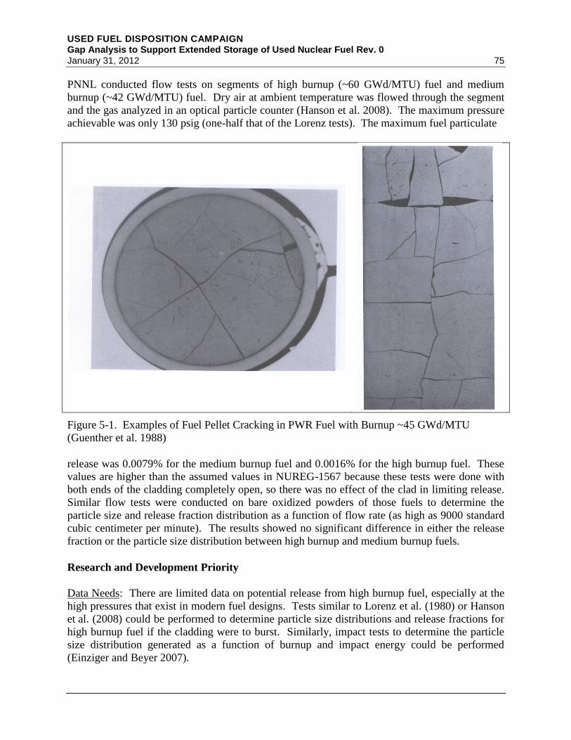
USED FUEL DISPOSITION CAMPAIGN Gap Analysis to Support Extended Storage of Used Nuclear Fuel Rev. 0 January 31, 2012 75
PNNL conducted flow tests on segments of high burnup (~60 GWd/MTU) fuel and medium
burnup (~42 GWd/MTU) fuel. Dry air at ambient temperature was flowed through the segment
and the gas analyzed in an optical particle counter (Hanson et al. 2008). The maximum pressure
achievable was only 130 psig (one-half that of the Lorenz tests). The maximum fuel particulate
Figure 5-1. Examples of Fuel Pellet Cracking in PWR Fuel with Burnup ~45 GWd/MTU
(Guenther et al. 1988)
release was 0.0079% for the medium burnup fuel and 0.0016% for the high burnup fuel. These
values are higher than the assumed values in NUREG-1567 because these tests were done with
both ends of the cladding completely open, so there was no effect of the clad in limiting release.
Similar flow tests were conducted on bare oxidized powders of those fuels to determine the
particle size and release fraction distribution as a function of flow rate (as high as 9000 standard
cubic centimeter per minute). The results showed no significant difference in either the release
fraction or the particle size distribution between high burnup and medium burnup fuels.
Research and Development Priority
Data Needs: There are limited data on potential release from high burnup fuel, especially at the
high pressures that exist in modern fuel designs. Tests similar to Lorenz et al. (1980) or Hanson
et al. (2008) could be performed to determine particle size distributions and release fractions for
high burnup fuel if the cladding were to burst. Similarly, impact tests to determine the particle
size distribution generated as a function of burnup and impact energy could be performed
(Einziger and Beyer 2007).

USED FUEL DISPOSITION CAMPAIGN Gap Analysis to Support Extended Storage of Used Nuclear Fuel Rev. 0
76 January 31, 2012
Regulatory Considerations: The limited data to date agree with the release fractions in
NUREG-1567. However, additional data, especially if it is shown that current release and
respirable size fractions are conservative, could facilitate a more risk-informed approach and
reduce reliance on other ITS SSCs.
Likelihood of Occurrence: No additional fuel fracturing of UO2 fuels is expected under normal
extended storage conditions. More detailed analyses of the forces to which fuel could be
subjected under various conditions (e.g., normal transfer and transportation, cask drop, or tip-
over) are needed to determine how likely fracturing is under off-normal or accident conditions.
Consequences: Release of the fine-grained HBS in high burnup fuels could contribute to a much
larger respirable fraction and complicate fuel retrievability. However, this is possible only under
accident conditions.
Remediation: There is no means of remediating the potential for fuel fracture other than to
reduce the possibility of accidents occurring.
Cost and Operations: Fuel fracture would have no impact under normal conditions. However,
the additional costs for retrieving and decontaminating systems with powdered spent fuel, such
as could be generated as a result of accident conditions, could be significant.
Future Waste Management Strategies: Fuel fracture is not expected to limit or complicate future
waste management strategies under normal conditions.
Therefore, additional research and development for evaluating fuel fracture is assigned a Low
priority.
5.1.3.2 Restructuring/Swelling
Literature Search and Degradation Mechanism Analysis
UO2 fuel pellets initially shrink during reactor operations as the fuel matrix undergoes
densification. At relatively low burnup, the fuel pellet begins to swell, largely as a result of
fission product and radiation damage accumulation. In addition, the cladding tends to creep
during reactor operations due to irradiation creep mechanisms that are not well understood. At
higher burnups, the fuel–clad gap is closed and the fuel is in direct contact with the cladding.
Often, this interaction results in bonding of the fuel pellet and cladding (Lee et al. 2004). In the
past, the fuel swelling and cladding creepdown often resulted in “bambooing” or “hourglassing,”
in which the cladding crept in more at the body of the pellets and less at the pellet–pellet
interfaces and resembled bamboo (Olander 2009). While better designs of both fuel and
cladding have reduced this bambooing effect, the differences in the pellet diameter, especially at
the interfaces with the chamfered edges, lead to local stresses that can result in pellet–clad
mechanical interaction (PCMI) failures. This is especially true during power transients and in
areas of the pellet that have been chipped or damaged (missing pellet surface) (Aleshin et al.
2010). While conditions during extended storage are obviously much less severe than during
reactor power transients, it is unknown if the local areas of hoop stress caused by pellet–clad

USED FUEL DISPOSITION CAMPAIGN Gap Analysis to Support Extended Storage of Used Nuclear Fuel Rev. 0 January 31, 2012 77
bonding can have any long-term effects on mechanisms such as clad creep or stress corrosion
cracking (SCC).
As discussed previously, when the local burnup of a fuel rod exceeds about 40 GWd/MTU, the
microstructure of the fuel pellet changes at the pellet surface, forming the rim or HBS.
Formation of the HBS appears to be a function of both burnup and local temperature. There are
disagreements in the literature of whether the thermal conductivity of the HBS is actually lower
than the rest of the fuel or how the mechanical properties, such as hardness and fracture
toughness, are affected. As the formation of HBS is a function of burnup, there will be no
change or additional restructuring during extended storage.
Research and Development Priority
Data Needs: Additional data to definitively show the effects of HBS on fuel properties such as
thermal conductivity, hardness, and fracture toughness are desired. Modeling and simulation to
calculate local hoop stress from pellet–clad bonding and thermal expansion/contraction at the
temperatures of interest for extended storage should be performed to determine if the stresses are
large enough to cause localized creep or SCC. The effects on clad behavior are considered in
Section 5.2.
Regulatory Considerations: 10 CFR 72.122 (h) requires that unless the rods or assemblies are
canned or otherwise confined, the cladding must be protected against gross ruptures. Most
ISFSIs currently do not can undamaged fuel, so the implication is that gross degradation of
undamaged cladding must not occur during dry storage.
Likelihood of Occurrence: No additional fuel restructuring or swelling is expected under
extended storage conditions.
Consequences: The impacts of fuel swelling alone on clad mechanisms such as creep or PCMI
are not known. Clad failures would be expected to be small, such as pinhole or hairline cracks,
releasing only fission gas. However, in the event of exposure to an oxidizing environment, fuel
oxidation could occur (see Section 5.1.3.4).
Remediation: There is no means of remediating fuel restructuring or swelling during storage.
Cost and Operations: Fuel restructuring or swelling would have no impact under normal
conditions.
Future Waste Management Strategies: Fuel restructuring or swelling is not expected to limit or
complicate future waste management strategies.
Therefore, additional research and development for evaluating fuel restructuring or swelling is
assigned a Low priority.

USED FUEL DISPOSITION CAMPAIGN Gap Analysis to Support Extended Storage of Used Nuclear Fuel Rev. 0
78 January 31, 2012
5.1.3.3 Fission Product Attack on Cladding
Literature Search and Degradation Mechanism Analysis
The phenomenon of pellet-clad interaction (PCI) is fairly well understood. It involves SCC of
the cladding as a result of the combination of an aggressive environment, a tensile stress, and a
susceptible material. In this case, the aggressive environment is caused by the fission products
iodine, cesium, and cadmium that are known to promote SCC. PCI occurs during power ramps
under normal operation (reactor startup or mid-cycle maneuvers) as a result of thermal expansion
of the pellet, closure of the pellet-cladding gap, and the ensuing buildup of cladding tensile
stresses. While PCI failures have occurred in both PWRs and BWRs, they have been more
prevalent in BWRs that use control rod movement to adjust reactor power, whereas PWRs
typically use soluble boron in the reactor coolant water.
To help reduce PCI failures, the industry first reduced local cladding strains by changing the
pellet design to include a chamfer at the edges and dishes at the ends of the pellets. BWR
vendors then introduced liner or barrier fuels in which a thin liner (of pure Zr metal under the
original General Electric design) was included on the fuel side of the cladding. This softer layer
reduces the local stress. Addition of Fe to the Zr liner improves the corrosion resistance, and
Westinghouse now uses a ZrSn liner (Dag et al. 2010). Had it not been for these design changes,
it is highly likely that PCI failures would have increased significantly with higher burnup
because the fission product inventory is higher, the fission gas release (and thus internal rod
pressure) is higher, fuel pellet swelling is greater, and fuel–clad bonding occurs. These factors
would have increased both the aggressive environment and the tensile stress.
The lower fuel temperatures in dry storage, especially at extended times, should not promote an
additional release of I, Cs, or Cd. As the temperatures decrease, so will the rod internal pressure,
alleviating much of the tensile stress. Thus, the driving forces for PCI failure will not increase,
and, in fact, the stress will decrease with extended storage.
Research and Development Priority
Data Needs: There are only limited data on the new clad materials compared to Zircaloy-2 and
Zircaloy-4. However, the newer clad materials tend to incorporate design changes, such as the
liners, reducing the probability of PCI failure. Because the chemical driver for SCC is not
expected to change during dry storage, further degradation of the cladding is covered in
Section 5.2.
Regulatory Considerations: 10 CFR 72.122 (h) requires that unless the rods or assemblies are
canned or otherwise confined, the cladding must be protected against gross ruptures. Most
ISFSIs currently do not can undamaged fuel, so the implication is that gross degradation of
undamaged cladding must not occur during dry storage.
Likelihood of Occurrence: No additional fission product release leading to PCI is expected
under extended storage conditions.
USED FUEL DISPOSITION CAMPAIGN Gap Analysis to Support Extended Storage of Used Nuclear Fuel Rev. 0 January 31, 2012 79
Consequences: PCI failures would be expected to be small, such as pinhole or hairline cracks,
releasing only fission gas. However, in the event of exposure to an oxidizing environment, fuel
oxidation could occur.
Remediation: There is no means of remediating fission product attack on cladding during
storage other than minimizing time at higher temperatures.
Cost and Operations: Fission product attack would have no impact under normal conditions.
Future Waste Management Strategies: Fission product attack is not expected to limit or
complicate future waste management strategies.
Therefore, additional research and development for evaluating fission product attack on cladding
is assigned a Low priority.
5.1.3.4 Fuel Oxidation
Literature Search and Degradation Mechanism Analysis
Oxidation of UO2 is a thermally activated process. As the temperature decreases, the rate of
oxidation also decreases significantly. Oxidation of UNF has also been shown (Hanson 1998) to
be a function of burnup, with higher burnup fuels being significantly more resistant to formation
of oxides with O/M ratios above 2.4. There has been some concern that the highly porous HBS
in high burnup fuels would oxidize rapidly, but the results in Hanson et al. (2008) have shown
that is not the case.
The concern with fuel oxidation is that first the grain boundaries are oxidized, potentially
releasing additional fission gases and the potential production of fine particulate matter as grain
decohesion occurs. Next, if oxidation to form U3O8 occurs, a phase that is 36% less dense than
the starting UO2, the fuel will swell and can result in unzipping (propagation of a crack) of the
cladding which would allow fuel relocation. This could impact retrievability, confinement,
radiation protection, and subcriticality safety functions.
For fuel oxidation to occur, an oxidizing environment must be present. This can occur if the
cask/canister is mistakenly backfilled with air instead of an inert gas. Depending on the size of
the cask, there would still be only enough oxygen present to oxidize one or two rods
(EPRI 1998). An oxidizing environment could also be present if there is a breach in the
cask/canister seal or if too much water was left in the cask after drying. The water could then
undergo radiolysis and form hydrogen, oxygen and highly oxidizing species like H2O2. There
also must be a through-wall failure in the cladding to expose the fuel to the oxidizing
environment. Given that the only occurrences of fuel oxidation can be under off-normal or
accident conditions, and that the decreasing temperatures for extended storage do not facilitate
oxidation to the higher states, this mechanism is of low importance.

USED FUEL DISPOSITION CAMPAIGN Gap Analysis to Support Extended Storage of Used Nuclear Fuel Rev. 0
80 January 31, 2012
Research and Development Priority
Data Needs: Sufficient data exist to model fuel oxidation for extended storage. Very minimal
data exist for the oxidation behavior of the HBS, and additional data are necessary to confirm
that the much smaller grain structure does not accelerate oxidation.
Regulatory Considerations: 10 CFR 72.122 (h) requires that unless the rods or assemblies are
canned or otherwise confined, the cladding must be protected against gross ruptures. Most
ISFSIs currently do not can undamaged fuel, so the implication is that gross degradation of
undamaged cladding must not occur during dry storage.
Likelihood of Occurrence: Fuel oxidation requires both clad failure and the presence of an
oxidizing environment, which is an off-normal or accident condition.
Consequences: During the first 0–20 years when temperatures are high, rapid oxidation to form
U3O8 could occur, provided an oxidizing environment is present. This would have definite
impacts on retrievability and possible impacts on radiation protection, confinement, and
subcriticality.
Remediation: If conditions exist for an oxidizing environment, inerting the cask/canister will
stop the process, and reducing the temperatures would significantly slow the process.
Cost and Operations: Fuel oxidation would have no impact under normal conditions. If it
occurs, it could have significant impact on retrievability because the fuel will be a fine, highly
dispersible powder.
Future Waste Management Strategies: Fuel oxidation is not expected to limit or complicate
future waste management strategies.
Therefore, additional research and development for evaluating fuel oxidation is assigned a Low
priority.
5.1.4 Fuel Summary Table
Table 5-1. Degradation Mechanisms That Could Impact the Performance of the Fuel
Stressor
Degradation
Mechanism
Influenced by
Extended Storage
or Higher Burnup
Additional
Data Needed
Importance of
R&D
Thermal and
Mechanical
Fuel fragmentation Yes Yes Low
Restructuring/swelling Yes Yes Low
Chemical Fission product attack
on cladding
Yes Yes Low
Fuel oxidation Yes Yes Low

USED FUEL DISPOSITION CAMPAIGN Gap Analysis to Support Extended Storage of Used Nuclear Fuel Rev. 0 January 31, 2012 81
5.1.5 Approach to Closing Fuel Gaps
The priority for addressing UO2 fuel data gaps is low; however, that priority will change for
MOX or advanced fuels. One reason for the low priority is the ongoing work being performed
internationally, most notably by Rondinella and others in Germany. The UFDC will continue
collaboration with these international partners to obtain additional data on fuel properties,
especially of the HBS. Modeling and simulation of the fuel are desired so that an accurate
understanding of the fuel and source term at the beginning of dry storage is available. Additional
testing, in collaboration with international partners, to obtain information on the fraction and
particle size distribution of fuel released under various scenarios, especially for rod rupture or
breakage from impact during design basis accidents, would be important in demonstrating the
consequences of various accidents. These data could be especially valuable if other SSC
degradation is significant or if the data are not available and alternative means of meeting
regulatory requirements are necessary.
5.2 Cladding
5.2.1 Introduction
The initial material used for cladding in commercial LWRs was austenitic stainless steel.
However, stainless steel is quite susceptible to SCC under reactor operating conditions, and the
fuel failure rate was high. In addition, the defects themselves were large, often resulting in rod
breakage. Another issue with stainless steel cladding is that Fe, which is obviously the main
component, and Ni have a relatively significant thermal neutron absorption cross section and
thus have an adverse effect on the overall reactor neutron economy. Because of these issues, the
industry began to move to different clad materials by the early 1980s.
To understand the drivers behind the choices for different cladding materials, it is important to
first understand a few of the major differences between PWRs and BWRs. Most obviously, the
coolant in a BWR boils whereas in a PWR it does not. There are thus significant differences at
the clad–water or clad–steam interface that affect corrosion and hydrogen uptake. Second,
PWRs generally operate at slightly higher temperatures, again affecting corrosion rates,
especially in the steam generators of the PWRs, which contribute significantly to the buildup of
crud on the cladding. Because of this, the coolant chemistry is different with PWRs using a
hydrogen overpressure or hydrazine in the coolant to create a reducing environment. The BWR
coolant, on the other hand, is oxidizing. PWRs also use boric acid to control reactor reactivity
and LiOH, both of which affect the coolant pH. Thus, there are significant differences between
PWRs and BWRs and the potential corrosion mechanisms that affect the choice for cladding
material.
Zirconium has a very low neutron cross section, making it ideal for use as a cladding material.
However, pure zirconium does not have the necessary mechanical properties and corrosion
resistance and thus must be alloyed with other materials, giving rise to the term Zircaloy.
Zircaloy-2 (Zry-2) was chosen as the cladding for use in BWRs. Zry-2 contains Fe, Sn, Cr, Ni,
and O to achieve the mechanical and corrosion-resistance properties needed. Zry-2 is still used
almost exclusively in BWRs today. However, to help mitigate the effects of PCI/PCMI, most

USED FUEL DISPOSITION CAMPAIGN Gap Analysis to Support Extended Storage of Used Nuclear Fuel Rev. 0
82 January 31, 2012
BWR fuels now use the “softer” liner or barrier of zirconium with small additions of Fe or Sn
(Dag et al. 2010).
Because both Ni and Sn have been shown to increase uniform corrosion in the hydrogenated
environments typical of PWRs, Zry-4 was chosen as the cladding for use in PWRs. As the
burnup and duty have increased, it was determined that Zry-4 did not exhibit sufficient corrosion
resistance. The first step to address this issue was to reduce the Sn content in Zry-4. ZIRLO™
was introduced by Westinghouse in the early 1990s to provide additional margin for corrosion
and growth compared to Zry-4 (Mitchell et al. 2010). To further reduce corrosion by up to 40%
compared to ZIRLO™ by further reducing the Sn content, Westinghouse introduced Optimized
ZIRLO™ as lead test assemblies in 2003. AREVA, on the other hand, developed the M5® alloy
that is the reference cladding for all AREVA PWR designs (Mardon et al. 2010). M5®
contains
< 100 ppm Sn. ZIRLO™, Optimized ZIRLO™, and M5® all contain about 1.0 wt% Nb.
It is important to stress that each of these alloys is actually a family of alloys. As an example,
ASTM B811-02 specifies the ranges of composition for each element to still be considered that
alloy. The actual composition is something to be agreed upon between the fuel vendor and the
purchasing utility. Chemical composition is not the only difference in the cladding types. The
crystallographic texture and microstructure (such as grain size and orientation) of the cladding all
play a role in the performance (Rudling et al. 2009). For example, Garzarolli et al. (2010) state
that it is known that the creep rates of recrystalized and annealed (RXA) cladding are lower than
that of cold-worked and stress relief annealed (CWSRA) cladding. For this and similar reasons,
most U.S. vendors changed from using CWSRA claddings to RXA claddings for BWRs while
also increasing the wall thickness to account for a lower yield strength. Only AREVA still uses
CWSRA Zry-2 cladding in the United States.
Garzarolli et al. (2010) also conclude that the formation of radial hydrides in RXA cladding at
high burnup is higher than for CWSRA cladding because the grain boundaries in RXA material
are isotropically distributed. Thus, the RXA material has more grain boundaries in the radial
direction than the CWSRA cladding, in which grain boundaries are elongated in the
circumferential plane. Garzarolli et al. present arguments for changing BWR Zry-2 cladding
back to CWSRA. In addition, Westinghouse is developing the AXIOM™ cladding, a
Nb-bearing alloy like ZIRLO™ but with zero Sn, that changes from the stress relief annealed
(SRA) condition to either partially recrystallized (pRXA) or fully RXA (Pan et al. 2010).
Irradiation is known to have a significant impact on the properties and performance of Zircaloy
cladding and structural materials. High-energy neutrons (>1 MeV) are known to produce two
different dislocation loops, the <a> and <c> loops. The size and density of the dislocation loops
alter the mechanical properties, specifically the strength (e.g., hardness, tensile strength, burst
strength) and ductility (e.g., uniform and total elongation strains). Irradiation increases the
cladding strength and decreases the cladding ductility by creating these dislocation loops and by
changing the configuration (amorphization) of the second-phase precipitates (SPPs) such as
Zr(Nb,Fe)2. The processes that lead to dislocation formation or SSP amorphization depend on
the material temperature; as a result, the irradiation temperature has an important effect on the
cladding microstructure and consequently the mechanical properties. Higher irradiation
temperatures result in larger <a> loop dislocations, whereas <c> loops do not form at 77°C

USED FUEL DISPOSITION CAMPAIGN Gap Analysis to Support Extended Storage of Used Nuclear Fuel Rev. 0 January 31, 2012 83
(EPRI 2006). Thermal annealing, such as can occur at the higher clad temperatures during
drying or initial dry storage, can result in a dramatic decrease in hardness and corresponding
increase in ductility.
It is clear that modeling the long-term properties of cladding will be complex and depend on clad
type (alloy), annealed condition (CWSRA vs. pRXA vs. RXA), irradiation history, and thermal
history to account for annealing. Advanced modeling and simulation will play a key role in
understanding these various influences on clad behavior. Advanced modeling and simulation is
of importance also to establishing the link between the vast database available on behavior of
unirradiated cladding to the minimal data available on actual UNF cladding. Establishing this
link through a science-based approach combining theory, experiment, and modeling and
simulation will provide the most cost-effective means in projecting the condition of the clad at
the end of extended storage.
Finally, it cannot be overemphasized that when analyzing cladding behavior, it is not necessary
for an individual mechanism to result in failure during extended storage. Instead, the ability of
the cladding to perform its necessary function for fuel retrievability and confinement for post-
storage transportation and handling at the end location (whether that be a geologic repository or a
reprocessing facility) is important. For example, the cladding may not creep to failure, but if the
cladding creep has resulted in places thin enough to fail because of the stresses of normal
transportation or handling or from design basis accidents, then that must be determined and
accounted for. Similarly, if cladding is desired as a barrier at the end location, then care must be
taken during extended storage to not jeopardize its integrity.
5.2.2 Analysis of Safety Functions
Degradation of the cladding affects the five storage safety functional areas as follows:
Retrievability: Cladding plays a very important role in retrievability. If the cladding remains
intact and undamaged (e.g., limited bowing), then retrieving the fuel for transfer to transportation
casks, waste packages, or to a reprocessing facility is relatively simple. For this reason, 10 CFR
72.122 (l) requires storage system designs to allow ready retrieval. SFST-ISG-2 defines “ready
retrievable” as remaining structurally sound (i.e., no gross degradation) and being able to be
handled by normal means (see Section 2.4.2).
Thermal Performance: To keep the cladding from experiencing gross degradation (defined as a
defect larger than 1 mm), NUREG-1536 and SFST-ISG-11 (NRC 2003a) suggest guidance to
maintain the maximum calculated fuel cladding temperature below 400°C. The decay heat from
the fuel is transferred to the cladding. Ensuring the ability of the cladding to transfer heat to the
DCSS (such as through radiative heat transfer) is important.
Radiological Protection: Cladding can serve as a contributor to radiologic dose because of the
activation products contained within the cladding itself or because of radionuclides trapped in the
external oxide or crud layers. The largest contributor to dose associated with the cladding is 60
Co, with a half-life of about 5.3 years. Thus, it is no longer considered as contributing to dose
after about 53 years (or 10 half-lives).

USED FUEL DISPOSITION CAMPAIGN Gap Analysis to Support Extended Storage of Used Nuclear Fuel Rev. 0
84 January 31, 2012
Confinement: Current regulations allow for breached or damaged UNF to be placed in DCSS
where damaged fuel is placed in a damaged fuel can. The implication is that NRC does not
consider the fuel or cladding as a confinement barrier (see Section 2.4.3). However, in
NUREG-1567 (Section 9.5.2.2), the NRC requires the applicant to perform a confinement
analysis based on assuming that 1% of the rods are broken (through-wall cladding defect) for
normal conditions, 10% for off-normal conditions, and 100% for design basis accident and
extreme natural phenomena. Obviously, if the program is able to show that these values, and
thus source term, are conservatively high, then there can be reduced reliance on other ITS SSCs.
However, as with retrievability, the ability of the cladding to maintain confinement of the fuel
during extended storage is of importance to subsequent transportation and handling at the end
location.
Subcriticality: Cladding plays a role in maintaining the geometric configuration that is important
to subcriticality. If cladding fails and fuel relocates, the ability to maintain subcriticality for
flooded configurations may be compromised. This is more important for wet retrieval and
transportation operations because there is no credible scenario for water in the DCSS for normal,
off-normal, or accident conditions during dry storage.
Importance of System to Licensing: Because cladding has important roles in retrievability and
confinement, and some role in thermal performance and subcriticality, the overall importance of
cladding to licensing is High.
5.2.3 Discussion of Selected Cladding Issues
Degradation mechanisms for cladding during extended dry storage and additional research and
development needs are discussed and prioritized in this section.
5.2.3.1 Annealing of Radiation Damage
Literature Search and Degradation Mechanism Analysis
Radiation damage, typically in the form of dislocation loops that affect the strength and ductility
of the cladding, is a function of the fast neutron fluence and irradiation temperature. Thermal
annealing, or recovery of this radiation damage, also appears to be related to the fast neutron
fluence that caused the damage, the annealing temperature, and the composition of the alloy
(EPRI 2006). One important conclusion of EPRI (2006) is that low-fluence data are not relevant
to the cases of high burnup fuels with fast neutron fluences (E > 1 MeV) sometimes exceeding
100×1020
n/cm2. It was also shown that Nb, such as used in ZIRLO™ and M5
® cladding, affects
the thermal recovery by increasing the onset temperature relative to Zry-2. Zircaloy with low
oxygen content recovered at a lower temperature than normal-oxygen Zircaloy.
The overwhelming majority of annealing studies are performed for very short times (about
1–2 hours) at elevated temperatures (400°C or higher), mostly to simulate in-reactor problems
like reactivity insertion accidents or loss-of-coolant accidents. The data of Ito et al. (2004) are
some of the only data directly applicable to extended storage of UNF. The authors tested both
SRA Zry-4 and RXA Zry-2 and reported the results of micro-Vickers hardness tests as a function
USED FUEL DISPOSITION CAMPAIGN Gap Analysis to Support Extended Storage of Used Nuclear Fuel Rev. 0 January 31, 2012 85
of time at annealing temperature. Hardness continued to recover, albeit quite slowly, at
temperatures as low as 330°C over 8000 hours (0.9 year), and nearly 50% recovery was observed
over the same time at 360°C. Thus, over the many years of extended storage, it is very possible
that thermal annealing will decrease the hardness and increase ductility. This would lessen the
chance of breakage from mechanical shock but could facilitate creep (see Section 5.2.3.9).
Thermal annealing also has the potential to release hydrogen trapped in dislocation loops or with
the SPPs. This could ultimately affect the hydrogen-related phenomena discussed in
Sections 5.2.3.5 and 5.2.3.6.
Research and Development Priority
Data Needs: The results of Ito et al. (2004) demonstrate that low-temperature thermal annealing
is possible. Additional data, especially for the newer alloys such as ZIRLO™ and M5® that
routinely achieve higher burnup, are necessary. EPRI (2006) recommends that sufficient testing
be performed over a range of temperatures, all else constant, to determine if an Arrhenius
relationship (with appropriate activation energies) is applicable. Considering the large number
of variables that may impact the data, including total fast neutron fluence, cladding type,
cladding microstructure, irradiation temperature, and annealing temperature, it is strongly
suggested that advanced modeling and simulation be combined with testing.
Regulatory Considerations: Regulations and guidance imply that if the cladding is classified as
undamaged when loaded into a dry storage cask, it should remain undamaged throughout the
storage period to meet the ready retrieval requirement.
Likelihood of Occurrence: For many years, it was assumed that low-temperature annealing did
not occur. The results of Ito et al. (2004) demonstrate that this mechanism is likely to occur over
extended storage.
Consequences: Thermal annealing will reduce the cladding hardness caused by radiation
damage. It may increase the ductility. There is also the possibility of releasing additional
hydrogen as SPPs anneal. Thermal annealing may actually be beneficial to cladding
performance for subsequent transportation and handling at the end location.
Remediation: Annealing happens faster at higher temperatures. Keeping the temperature low,
either during drying or the initial stages of storage, will result in longer times for annealing.
However, if the low-temperature annealing occurs over the period of extended storage, then no
remediation is possible.
Cost and Operations: Thermal annealing, with the exception of possible additional hydrogen
release, would have positive effects on cladding hardness but no impact on cost or operations
under normal conditions. It may alleviate some problems of handling and be a cost benefit.
Future Waste Management Strategies: No impact.

USED FUEL DISPOSITION CAMPAIGN Gap Analysis to Support Extended Storage of Used Nuclear Fuel Rev. 0
86 January 31, 2012
Therefore, additional research and development for evaluating annealing of radiation damage is
assigned a Medium priority.
5.2.3.2 Metal Fatigue Caused by Temperature Fluctuations
Literature Search and Degradation Mechanism Analysis
NUREG-1536 and SFST-ISG-11 recommend limiting temperature cycling during drying and
loading operations to less than 10 cycles with cladding temperature variations that are less than
65°C each. With extended storage times when the fuel has cooled sufficiently, it is possible that
seasonal temperature fluctuations could cause small thermal cycling of the cladding. There is
also an increased likelihood of extreme weather conditions that could influence the internal
DCSS temperatures. Such temperature variations, if large enough, could result in metal fatigue.
Research and Development Priority
Data Needs: Analyses of temperature profiles (axial and radial) of low and high burnup fuels
over the entire period of dry storage, taking into account normal and off-normal environmental
conditions (see Section 4.1), are needed to determine the extent of metal fatigue caused by
temperature fluctuations.
Regulatory Consideration: Ensuring that cladding fatigue caused by temperature fluctuations
does not occur is important to maintaining fuel configuration for retrievability.
Likelihood of Occurrence: It is unlikely that temperature fluctuations will result in failure or
weakening of cladding.
Consequences: Cladding fatigue to failure is not expected to occur under normal conditions of
extended storage but may become an issue during storage design basis accidents and
transportation hypothetical accident conditions such that the confinement the cladding provides
would be changed and fuel retrievability might be complicated.
Remediation: The effects of cladding fatigue cannot be readily remediated.
Cost and Operations: Cladding fatigue is not expected to have an impact on costs or operations.
Future Waste Management Strategies: Cladding fatigue is not expected to limit or complicate
future waste management strategy.
Therefore, additional research and development for evaluating cladding fatigue caused by
temperature fluctuations is assigned a Low priority.

USED FUEL DISPOSITION CAMPAIGN Gap Analysis to Support Extended Storage of Used Nuclear Fuel Rev. 0 January 31, 2012 87
5.2.3.3 Phase Change
Literature Search and Degradation Mechanism Analysis
A change in phase (e.g., from α to β) can affect the mechanical properties of the cladding. Such
phase changes are dependent on the type of alloy (e.g., Zry-2 or Zry-4) and the microstructure of
the cladding. It is known that this phase change for Zry-2 and Zry-4 is approximately 810°C.
This temperature is much higher than for normal dry storage or off-normal conditions. While the
effects of higher burnup, newer clad alloys with different chemical compositions, and clad
morphology (CWSRA vs. RXA) on phase changes are not known, it is anticipated that any phase
changes would still be at temperatures applicable to only scenarios such as a beyond design basis
fire.
Research and Development Priority
Data Needs: Determining the temperature for deleterious phase changes and amorphization
effects are needed for newer cladding alloys.
Regulatory Considerations: Ensuring that cladding phase change does not occur and affect the
mechanical properties of the cladding is important to maintaining fuel configuration for
retrievability.
Likelihood of Occurrence: Phase changes are unlikely except for beyond design basis accidents.
Consequences: Phase changes in the cladding may affect properties like strength.
Remediation: There is no remediation if phase changes occur under beyond design basis
accidents.
Cost and Operations: Phase change in cladding is not expected to affect cost or operations under
normal conditions.
Future Waste Management Strategies: Cladding phase change is not expected to limit or
complicate future waste management strategy.
Therefore, additional research and development for evaluating cladding phase chance caused by
temperature fluctuations is assigned a Low priority.
5.2.3.4 Emissivity Changes
Literature Search and Degradation Mechanism Analysis
The maximum heat flux (W/m2) for radiative heat transfer is proportional to the surface
temperature raised to the fourth power. The proportionality constant is the Stefan–Boltzman
constant. In real systems, the proportionality constant must be multiplied by the material’s
emissivity. Emissivity, ε, is a radiative property of the surface whose value is in the range 0 ≤ ε
≤1 and indicates how efficiently the material surface emits compared to an ideal radiator. The

USED FUEL DISPOSITION CAMPAIGN Gap Analysis to Support Extended Storage of Used Nuclear Fuel Rev. 0
88 January 31, 2012
value for emissivity is usually chosen to be conservatively low, thus yielding maximum peak
cladding temperatures. Cladding emissivity is dependent on oxide thickness as modeled for the
FRAPCON 3.4 and FRAPTRAN 1.4 codes (Luscher and Geelhood 2010). Most of the data used
to develop this correlation for emissivity are for Zircaloy in steam at high oxide thicknesses
typical of reactor accident conditions. Thus, to calculate more accurate temperature profiles and
cladding temperatures, it would be necessary to determine actual emissivities for UNF cladding
under storage conditions. The result would be in lowering the calculated temperatures, which
could be important in knowing when high burnup cladding might transition to a more brittle
condition (see Section 5.2.3.5). However, an upper bound on emissivity can be used to calculate
what the lowest clad temperatures might be.
During storage, it is possible that crud or oxide layers could spall and change the emissivity.
Under normal conditions (inert environment), there will not be growth of crud or oxide layers, so
the original calculations are bounding. The only other possible change to the clad emissivity
could result from coatings (such as Zn or Ni) from the cask/canister internals vaporizing and
plating out on the cladding.
Research and Development Priority
Data Needs: Determining actual clad emissivities as a function of oxide and crud layer
thicknesses under dry storage conditions is necessary to calculate actual temperature profiles (see
Section 4.1). However, before proceeding with this difficult and expensive task, simple
sensitivity analyses using the COBRA-SFS code (Michener et al. 1995) can be performed to
determine how changing emissivity over a realistic range affects the clad temperatures.
Regulatory Considerations: NUREG-1536 recommends keeping the maximum cladding
temperature below 400°C. By assuming conservative emissivities, the calculations are
conservative and actual temperatures are lower.
Likelihood of Occurrence: Changes in emissivity under normal conditions are low.
Consequences: Emissivity changes could only cause the actual temperatures to be lower than are
already conservatively modeled.
Remediation: There is no remediation for emissivity changes.
Cost and Operations: Emissivity changes are not expected to affect cost or operations.
Future Waste Management Strategies: Emissivity changes are not expected to limit or
complicate future waste management strategy.
Therefore, additional research and development for evaluating cladding emissivity changes is
assigned a Low priority. If the temperature profile modeling (Section 4.1) suggests a very strong
dependence and large temperature differences, then this priority could be raised.

USED FUEL DISPOSITION CAMPAIGN Gap Analysis to Support Extended Storage of Used Nuclear Fuel Rev. 0 January 31, 2012 89
5.2.3.5 Hydrogen Effects: Embrittlement and Reorientation
Literature Search and Degradation Mechanism Analysis
During reactor operations, the cladding undergoes outer surface corrosion as the high-
temperature water reacts with the cladding, producing a zirconium oxide layer. As noted above,
a number of factors, but especially the alloy composition, influences the rate of oxide layer
formation. Hydrogen is released during this chemical reaction, and a fraction of this hydrogen is
absorbed by the Zircaloy (hydrogen pickup). The solubility of hydrogen in zirconium is highly
temperature-dependent, with increased solubility at higher temperatures. When the
concentration of hydrogen exceeds the solubility limit, zirconium hydrides form. Depending on
the size, distribution, and orientation, these hydrides can embrittle the cladding and reduce
ductility. Furthermore, the presence of hydrides can facilitate cracking if the hydrides are
aligned radially, perpendicular to the tensile stress field. Cladding hydrides are typically
observed to be oriented in the circumferential direction but can reorient to the radial direction,
depending on the stress level of the cladding when it is cooled from a higher temperature, such as
will occur following the drying process. Hydrides have also been shown to diffuse to colder
regions of the cladding under a relatively small temperature gradient. The reorientation and
diffusion of hydrides can result in cracking of the cladding. Even if a through-wall crack is not
formed, the extent of cracking needs to be modeled to determine if clad will then fail due to
stresses caused by normal handling or transportation.
High burnup cladding is characterized by a coolant-side corrosion layer (10 to 100 µm thick), a
dense hydride rim (for > 150 weight parts per million [wppm] hydrogen pickup), a radiation-
hardened zirconium-alloy matrix with a low concentration of hydrides (<140 wppm), and a thin
fuel-side oxide layer, which contains fission products and actinides. The hydrides are basically
platelets oriented in the circumferential direction. However, the corrosion-layer thickness,
hydrogen pickup, and distribution of hydrides are highly dependent on cladding alloy and
texture, operating conditions (e.g., coolant temperature and cladding heat flux), and burnup.
Examples of hydride distribution and hydrogen content for high burnup PWR cladding alloys
(Zry-4, ZIRLO™, and M5®) are shown in Figures 5-2 through 5-5. From Figure 5-2, it can be
seen that the corrosion layer and hydrogen content for Zry-4 at 64 GWd/MTU increase
significantly with axial location due to the increase in coolant temperature. Figure 5-3 shows the
hydride morphology and distribution for high-burnup ZIRLO™ cladding at a burnup above the
licensing limit (70 GWd/MTU) and at an axial location where the hydrogen pickup (650 wppm)
is close to the maximum value. At a location 0.7 m lower on the rod, the hydrogen content was
only 300 wppm and the corrosion layer was 26 µm thick. However, the hydride rim was well
developed at 300–750 wppm.
The increase in hydrogen content manifests itself as an increase in hydride rim thickness with
little change to the hydrogen content in the bulk of the cladding below the rim. Both high-
burnup ZIRLOTM
and Zry-4 cladding exhibit the same trends with regard to increase in hydrogen
content with increase in axial position and with regard to hydride distribution across the cladding
wall. Figure 5-4 shows that M5® has low hydrogen pickup (≈100 wppm) and thin corrosion
layer thickness (12 µm) even at high burnup (63 GWd/MTU). In terms of texture, M5® cladding
is RXA, while Zry-4 and ZIRLOTM
are CWSRA materials. BWR cladding consists of RXA
USED FUEL DISPOSITION CAMPAIGN Gap Analysis to Support Extended Storage of Used Nuclear Fuel Rev. 0
90 January 31, 2012
Zircaloy-2 with an inner liner of low-alloy Zr, which accounts for about 10% of the cladding
thickness. Due to the lower coolant temperature, hydrogen contents tend to be in the range of
100–300 wppm at the licensed discharge burnup of 62 GWd/MTU (Tsai and Billone 2003;
Nakatsuka et al. 2004). Aomi et al. (2008) show micrographs of hydride distribution and
morphology in Zr-lined Zry-2. BWR cladding differs from PWR cladding in that it contains a
higher hydrogen concentration near the cladding inner surface due to the liner. The high-burnup
cladding characterizations described above apply to fuel discharged from the reactor and fuel
stored in spent-fuel pools.
The mechanical properties of high-burnup cladding have been studied by subjecting the materials
to longitudinal (axial) tensile tests, ring-stretch tests, ring-compression tests, and biaxial tube
burst tests. At temperatures relevant to extended storage, the corrosion layer and the hydride rim
are brittle. The metal matrix has reduced ductility (compared to as-fabricated cladding) due to
irradiation-induced hardening. Based on axial tensile tests, there is a significant decrease in both
total and uniform elongation due to irradiation-induced hardening. For high-burnup Zry-2 and
Zry-4, mechanical properties can be found in MATPRO (NUREG/CR-6150, Siefken et al. 2001),
Garde (1989), Garde et al. (1996), Daum et al. (2008), and Aomi et al. (2008). Only limited data
are available in the literature for current PWR alloys ZIRLOTM
and M5® because Westinghouse
and AREVA consider such data to be proprietary. For the metal matrix below the hydride rim,
the reduction in ductility is due primarily to irradiation hardening. However, the presence of
brittle-corrosion and hydride-rim layers results in crack initiation at stresses lower than the
ultimate strength of the metal matrix. As toughness also decreases with irradiation, the metal
matrix may exhibit lower ductility due to the presence of the corrosion and hydride-rim layers.
Mechanical properties data for irradiated Zry-2 can be found in Aomi et al. (2008) and Yasuda
et al. (1987).
During the drying-transfer process and during storage, high-burnup cladding is subjected to
elevated temperatures (≤400°C based on SFST-ISG-11, Revision 3) and elevated pressures.
Technical specifications limit the internal pressure for most assemblies to be less than the coolant
pressure during normal operation for BWR (7.17 MPa, 1040 psia) and PWR (15.5 MPa,
2250 psia) fuel rods. For a limited number of rods, the internal pressure is limited to 1.3 times
the coolant pressure: BWR (9.32 MPa, 1350 psia) and PWR (20.2 MPa, 2925 psia). Such
internal gas pressures lead to PWR cladding hoop stresses in the range of 130 ± 20 MPa at 340°C
during drying and initial storage. For modern BWR cladding, the limiting internal gas pressures
lead to cladding hoop stresses in the range of 56 ± 6 MPa at 290°C. At 340°C average gas
temperature, the BWR stresses would be about 60 ± 7 MPa. At 400°C, the solubility of
hydrogen in Zr-based cladding alloys is about 200 wppm (Kearns 1967; Kammenzind et al.
1996). Cooling under conditions of decreasing stress with decreasing temperature may result in
a fraction of the hydrogen in solution precipitating as radial hydrides, which enhances cladding
embrittlement in response to hoop stresses. After cooling to 200°C, only about 15 wppm
hydrogen remains in solution. Thus, the hydride distribution across the cladding wall and the
hydride morphology are essentially fixed after a relatively short storage time at which the
cladding temperature drops below 200°C. The length and distribution of radial hydrides at this
point in storage time depends on the peak drying-storage temperature and internal pressure, the
cladding alloy, and the manufacturing process. High-burnup (45 to 62 GWd/MTU) cladding has
higher decay heat, higher internal pressure, and higher hydrogen content than low burnup

USED FUEL DISPOSITION CAMPAIGN Gap Analysis to Support Extended Storage of Used Nuclear Fuel Rev. 0 January 31, 2012 91
cladding. Therefore, it is more susceptible to radial hydride formation. Nb-bearing cladding
alloys and RXA alloys are more susceptible to radial-hydride precipitation than Sn-bearing
CWSRA alloys (e.g., Zry-4; Aomi et al. 2008; Burtseva et al. 2010).
The radial-hydride embrittlement issue for high-burnup cladding is emphasized in SFST-ISG-11,
Revision 3 (NRC 2003a). Based on data available at that time for pre-hydrided/non-irradiated
cladding materials, the following limits were imposed: 400°C peak cladding temperature during
drying-transfer-storage, less than 10 thermal cycles, and less than 65°C temperature drop during
each thermal cycle. However, data for high-burnup cladding were not available at that time.
Since then, the data generated by Daum et al. (2006, 2008), Aomi et al. (2008), and Burtseva
et al. (2010) strongly indicate that these limits are insufficient to prevent radial-hydride
formation and embrittlement at cladding temperatures < 200°C.
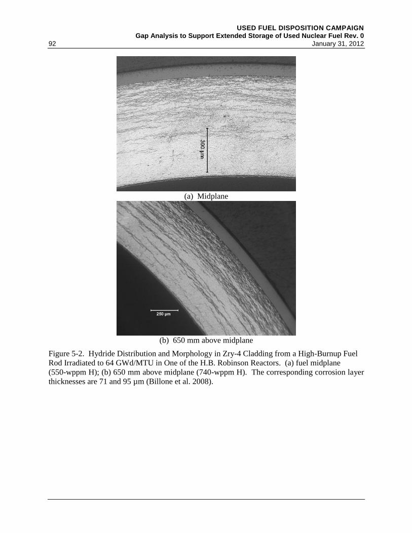
USED FUEL DISPOSITION CAMPAIGN Gap Analysis to Support Extended Storage of Used Nuclear Fuel Rev. 0
92 January 31, 2012
(a) Midplane
(b) 650 mm above midplane
Figure 5-2. Hydride Distribution and Morphology in Zry-4 Cladding from a High-Burnup Fuel
Rod Irradiated to 64 GWd/MTU in One of the H.B. Robinson Reactors . (a) fuel midplane
(550-wppm H); (b) 650 mm above midplane (740-wppm H). The corresponding corrosion layer
thicknesses are 71 and 95 µm (Billone et al. 2008).

USED FUEL DISPOSITION CAMPAIGN Gap Analysis to Support Extended Storage of Used Nuclear Fuel Rev. 0 January 31, 2012 93
(a) Thick hydride rim at ≈2910 mm from rod bottom
(b) Thin hydride rim ≈2910 mm from rod bottom
Figure 5-3. Hydride Distribution and Morphology of ZIRLOTM
Cladding from a High-Burnup
Fuel Rod Irradiated in the North Anna Reactors to 70 GWd/MTU: (a) circumferential region
with thickest (≈70 μm equivalent) hydride rim; and (b) circumferential location with thinnest
(≈40 μm equivalent) hydride rim. The dashed line in the images was used to estimate equivalent
(i.e., dense) thickness. The average hydrogen content at this location was 650 wppm with local
circumferential values from 500–840 wppm. The corresponding corrosion layer was 43-µm
thick (Billone et al. 2008).
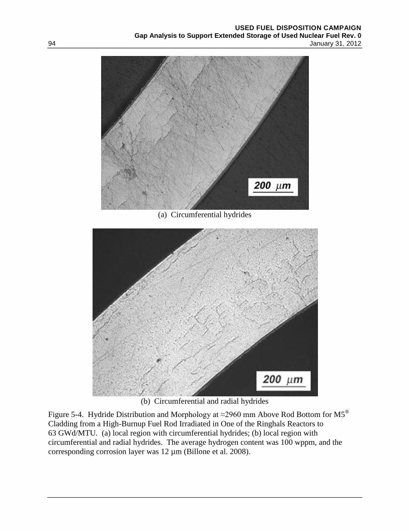
USED FUEL DISPOSITION CAMPAIGN Gap Analysis to Support Extended Storage of Used Nuclear Fuel Rev. 0
94 January 31, 2012
(a) Circumferential hydrides
(b) Circumferential and radial hydrides
Figure 5-4. Hydride Distribution and Morphology at ≈2960 mm Above Rod Bottom for M5®
Cladding from a High-Burnup Fuel Rod Irradiated in One of the Ringhals Reactors to
63 GWd/MTU . (a) local region with circumferential hydrides; (b) local region with
circumferential and radial hydrides. The average hydrogen content was 100 wppm, and the
corresponding corrosion layer was 12 µm (Billone et al. 2008).

USED FUEL DISPOSITION CAMPAIGN Gap Analysis to Support Extended Storage of Used Nuclear Fuel Rev. 0 January 31, 2012 95
(a) High-burnup ZIRLOTM
cladding, 425-wppm H, 110-MPa hoop stress at 400°C
(b) High-burnup ZIRLO
TM cladding, 720-wppm H, 140-MPa hoop stress at 400°C
Figure 5-5. Post-Drying Radial-Hydride Formation in High-Burnup ZIRLOTM
Cladding (a) with
425-wppm H Subjected to 110-MPa Hoop Stress at 400°C, and (b) with 720-wppm Subjected to
140-MPa Hoop Stress at 400°C . The samples were cooled at 5°C/h under decreasing stress
conditions. The average cladding hydrogen content was ≈200 wppm below the rim region
(Burtseva et al. 2010).
USED FUEL DISPOSITION CAMPAIGN Gap Analysis to Support Extended Storage of Used Nuclear Fuel Rev. 0
96 January 31, 2012
Aomi et al. (2008) subjected Zry-2 and Zry-4 to a single drying cycle with peak temperatures in
the range of 250–400°C and cooling rates of 30°C/hr, 3°C/hr, and 0.3°C/hr. They conducted
three types of tests to assess the effects of radial-hydrides on embrittlement: ring compression
tests, ring tensile tests, and longitudinal tensile tests. The ring tests, which impose hoop stress,
indicated significant loss of ductility and embrittlement at room temperature (RT) as peak
temperatures and stresses were increased during the drying cycle. Longitudinal tensile tests
indicated little-to-no effect of radial hydrides on axial tensile properties. Also, RXA Zry-2
appeared to be more susceptible to radial-hydride-induced embrittlement than SRA Zry-4.
Researchers at Argonne performed tests for NRC to determine radial-hydride formation and
embrittlement at the licensing limits: three with high-burnup ZIRLOTM
and two with high-
burnup Zry-4. Samples were pressurized at RT to give cladding hoop stresses of either 110 MPa
or 140 MPa at 400°C, annealed at 400°C for 1 to 24 hr, cooled at 5°C/hr, and subjected to ring
compression tests at 5 mm/s and RT to 200°C. The results of the first two tests with ZIRLOTM
have been documented and are available in NRC ADAMS (Burtseva et al. 2010). These results
show significant radial-hydride formation for peak cladding stresses of 140 MPa and 110 MPa
(see Figure 5-5). The ductile-to-brittle transition temperatures were about 200°C and about
150°C for the 140-MPa and 110-MPa test conditions, respectively. Clearly, the SFST-ISG-11,
Rev. 3 limits do not prevent radial-hydride formation and embrittlement for high-burnup
ZIRLOTM
. The Zry-4 results under the same test conditions indicated that Zry-4 is much less
susceptible to radial hydride formation than Nb-bearing ZIRLOTM
. Ductile-to-brittle transition
temperatures for Zry-4 were more than 100°C lower than for ZIRLOTM
under the same test
conditions.
Research and Development Priority
Data Needs: Significant data are needed to determine the effects of high burnup and different
clad alloys on hydrogen embrittlement and reorientation and their subsequent effect on the
ability of cladding to remain in the same condition it was in when emplaced in dry storage.
More detail is provided for each clad type. EPRI (2006) also recommends that to gain more
understanding of the relationship between radial and circumferential hydrides and hydrogen in
solution that hot-stage metallography be used, instead of room temperature as has been done to
date. They also recommend detailed transmission electron microscope microstructural
examinations.
1. High-Burnup Zircaloy-4 (Zry-4)
Most of the high-burnup PWR cladding in storage pools and dry-casks is Zry-4. The data of
Aomi et al. (2008) are limited to burnups ≤55 GWd/MTU, to RT testing, and to a very slow
ring-compression displacement rate (2 mm/min). The Argonne data (Billone et al. 2008)
included Zry-4 cladding with a burnup of 64 GWd/MTU, ring-compression test temperatures
of RT to 150°C, and a faster ring-compression displacement rate of 5 mm/s. More data are
needed to determine the effects of peak cladding temperature and pressure, the effects
temperature cycling during vacuum drying, and the effects of ring-compression temperature
and displacement rate on radial hydride embrittlement. In particular, the ductile-to-brittle
transition temperature needs to be established as a function of peak drying-storage conditions

USED FUEL DISPOSITION CAMPAIGN Gap Analysis to Support Extended Storage of Used Nuclear Fuel Rev. 0 January 31, 2012 97
to determine post-storage retrieval and transport temperatures for which the cladding retains
ductility and toughness. 150-MPa cladding hoop stress is a reasonable upper bound stress
during drying-storage. Data are needed on the effects of reduced drying-storage
temperatures (e.g., 400°C 350°C) on the ductile-to-brittle transition temperature.
2. High-burnup ZIRLOTM
In PWR reactors designed by Westinghouse, ZIRLOTM
has replaced Zry-4 for 17 × 17 fuel
array designs. The number of high-burnup 17 × 17 ZIRLOTM
assemblies in pool storage
continues to grow. Argonne results (Billone et al. 2008) indicate that Nb-bearing ZIRLOTM
is much more susceptible to radial-hydride-induced embrittlement than Zry-4 for peak
drying-storage temperatures of 400°C at cladding stresses as low as 110 MPa. Data are
needed to establish drying-storage peak temperatures and cycling limitations for which
ZIRLOTM
retains ductility at temperatures at least as low as RT. As these peak temperatures
may be too limiting with regard to cask loading, the ductile-to-brittle transition temperature
needs to be established as a function of drying-storage conditions. The data are needed to
establish post-storage retrieval and transport temperatures for which ZIRLOTM
retains
ductility.
3. High-Burnup M5®
In PWR reactors designed by AREVA, M5® has replaced Zry-4 for 17×17 fuel array designs.
Although the number of high-burnup 17×17 M5®
assemblies in pool storage is less than the
number of high-burnup 17×17 ZIRLOTM
assemblies, the number of high-burnup M5®
assemblies in pool storage continues to increase. No data are available for radial-hydride
formation and embrittlement in high-burnup M5® cladding. Such cladding has relatively low
hydrogen content. However, it may have a greater tendency to form radial hydrides because
it is Nb-bearing and is fabricated to have an RXA texture. Data are needed for this alloy at
peak drying-storage temperature (400°C) and hoop stress (150 MPa). If it does not retain
RT-ductility under these conditions, then additional data would be needed to determine
drying-storage conditions for which M5® retains RT ductility.
4. High-Burnup Zircaloy-2 (Zry-2)
Most of the high-burnup BWR cladding in reactors and in pool storage is Zry-2. The data of
Aomi et al. (2008) is relatively comprehensive for this alloy and show a high susceptibility to
radial-hydride formation and embrittlement. However, the dataset does not include the
effects of temperature cycling during drying and the effects of test temperatures higher than
RT and of higher displacement rates. Additional data are needed for Zry-2, as well as newer
BWR alloys developed by Global Nuclear Fuels (e.g., ZIRON).
Regulatory Considerations: During storage, the regulations and guidance imply that maintaining
the cladding in the same state as it was loaded, including preventing gross degradation, is
important to meeting the retrievability requirement. NRC has not given generic licenses to
transport casks loaded with high-burnup fuel assemblies because of the concern regarding radial-
hydride embrittlement in response to hoop stresses that would be induced during normal
USED FUEL DISPOSITION CAMPAIGN Gap Analysis to Support Extended Storage of Used Nuclear Fuel Rev. 0
98 January 31, 2012
transport conditions (includes 0.3-m drop) and hypothetical accident conditions (includes 9-m
drop).
Likelihood of Occurrence: Based on the recent, limited data presented here, the likelihood of
embrittlement for high burnup cladding is high. Reorientation and diffusion are likely.
Consequences: Brittle cladding is far more likely to break while being handled or transported or
during even design basis seismic events. This could lead to significant relocation of the fuel and
greatly complicate retrievability and even subcriticality during transportation accidents.
Remediation: It may be possible to devise drying processes that keep the cladding temperatures
and internal pressures low enough to prevent reorientation. To prevent the ductile to brittle
transition would require either keeping the fuel above the transition temperature or transporting
before it reaches that temperature.
Cost and Operations: If additional rods fail and break, the cost and complication to operations
would be significant.
Future Waste Management Strategies: Rod failure due to hydride embrittlement would
complicate loading options and remove cladding credit for future waste management strategies.
Therefore, additional research and development for evaluating cladding hydrogen effects from
embrittlement and reorientation is assigned a High priority.
5.2.3.6 Hydrogen Effects: Delayed Hydride Cracking
Literature Search and Degradation Mechanism Analysis
Delayed hydride cracking (DHC) is a time-dependent mechanism traditionally thought of as
diffusion of hydrogen to an incipient crack tip (flaw), followed by nucleation, growth, and
fracture of the hydride at the crack tip. The process continues as long as a sufficient stress to
promote the hydrogen diffusion occurs (Puls 2009, McRae et al. 2010). DHC has traditionally
been ruled out as a possible mechanism for cladding degradation during extended storage
because as the temperatures decrease, the stress decreases and becomes insufficient to promoter
crack propagation (BSC 2004a, EPRI 2002b, Rothman 1984). However, Rothman (1984) noted
that additional data are necessary for larger crack depths (~50% of wall thickness).
The earlier models did not account for the hysteresis in the hydrogen/zirconium solvus, which
has important effects on the temperature dependence of the DHC velocity (Puls 2005). This
hysteresis shows that the hydrogen concentration can be substantially higher on a cooling solvus
line than for a heating solvus line (Kim 2008).
DHC is a known failure mechanism in pressure tubes of Zry-2.5% Nb alloy as used in CANDU
and RBMK reactors (IAEA 2004) as well as in Zry-2 tubing used in the Hanford N-reactor
(Huang and Mills 1991). Simpson and Ells (1974) reported DHC failure of unirradiated
Zry-2.5% Nb specimens at room temperature over periods of four to five weeks to up to

USED FUEL DISPOSITION CAMPAIGN Gap Analysis to Support Extended Storage of Used Nuclear Fuel Rev. 0 January 31, 2012 99
24 months. Huang and Mills reported that cracking only occurred above a critical temperature
(180°C) when specimens were subjected to an over-temperature cycle. Below that temperature,
DHC occurred regardless of whether specimens were heated or cooled to the test temperature
(Huang and Mills 1991). Chao et al. (2008) report that the location of the crack is important in
determining whether or not the cladding will breach, with the greatest chance being when the
crack is located on the outer side of the cladding.
Kim (2009) has proposed a new model for DHC. In this model, creep deformation, prior creep
strain, higher burnup, the solvus hysteresis, and the γ to δ hydride phase transition all play
important roles in DHC. While there is much disagreement (EPRI 2002b; McRae et al. 2010)
with Kim’s model (Kim 2009), if Kim’s hypotheses are correct, then spent fuel will be more
likely to fail by DHC upon cooling below 180°C if there are stress raisers inside the rod such as
the end cap weld region or incipient cracks due to an interaction of fuel and cladding during
reactor operation. This may be one factor in explaining why DHC failure was not observed in
the 15-year demonstration project where the fuel temperature in an open cask (so lower than in
the sealed cask) was measured as 154°C. A second factor is that the fuel was of relatively low
burnup so the hydrogen concentration may have been too low for the mechanism proposed by
Kim to occur. The proposal of Kim that prior plastic deformation of the cladding may be a
preferential site for DHC needs to be examined further.
Nakatsuka et al. (2010) reported that DHC initiates in the metal at oxide cracks at the metal-
oxide interface at the outer diameter of Zr-2 RXA. These DHC tests have been performed at
constant temperature with hoop stress changing with time over a period of several (<25) minutes
using Zry-2 RXA cladding. Oxide cracking occurred at hoop stresses between 100 MPa and
170 MPa with strains of 0.21%. The zirconium hydrides in the metal were observed to begin
cracking between 200 to 350 MPa hoop stress with strains of 0.34%. Holston et al. (2010)
reported that DHC is only present at temperatures below 380°C (653K) in either Zry-2 or Zry-4
at constant temperatures for only a few minutes. This paper noted that for the conditions tested
several parameters had to be satisfied for DHC to be observed: 1) high hydrogen levels near
crack tip, 2) temperatures less than 380°C and 3) sufficient stress levels at crack tip (above
600 MPa) or stress riser (hydride tip).
Research and Development Priority
Data Needs: There is contradictory evidence as to whether DHC occurs at low temperatures,
such as would be expected during extended storage, so further investigation into Kim’s
hypothesis that prior plastic deformation of the cladding may be a preferential site for DHC
needs to be examined further. Also, there are limited data on the potential for DHC in higher
burnup fuels and newer clad alloys. Data over longer periods of time and at different stress and
plastic deformation levels to determine the stress and/or deformation thresholds for DHC are
needed.
Regulatory Considerations: During storage, the regulations and guidance imply that maintaining
the clad in the same state as it was loaded, including preventing gross degradation, is important
to meeting the retrievability requirement. DHC, even if not through-wall, could result in rod
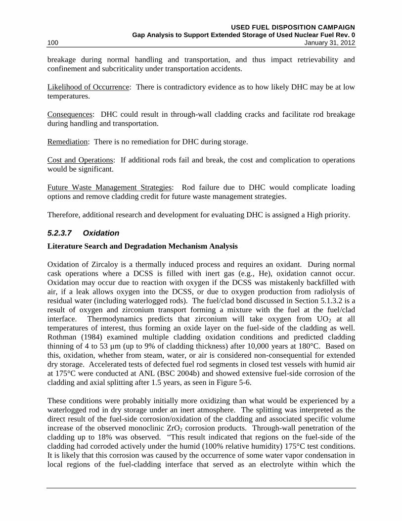
USED FUEL DISPOSITION CAMPAIGN Gap Analysis to Support Extended Storage of Used Nuclear Fuel Rev. 0
100 January 31, 2012
breakage during normal handling and transportation, and thus impact retrievability and
confinement and subcriticality under transportation accidents.
Likelihood of Occurrence: There is contradictory evidence as to how likely DHC may be at low
temperatures.
Consequences: DHC could result in through-wall cladding cracks and facilitate rod breakage
during handling and transportation.
Remediation: There is no remediation for DHC during storage.
Cost and Operations: If additional rods fail and break, the cost and complication to operations
would be significant.
Future Waste Management Strategies: Rod failure due to DHC would complicate loading
options and remove cladding credit for future waste management strategies.
Therefore, additional research and development for evaluating DHC is assigned a High priority.
5.2.3.7 Oxidation
Literature Search and Degradation Mechanism Analysis
Oxidation of Zircaloy is a thermally induced process and requires an oxidant. During normal
cask operations where a DCSS is filled with inert gas (e.g., He), oxidation cannot occur.
Oxidation may occur due to reaction with oxygen if the DCSS was mistakenly backfilled with
air, if a leak allows oxygen into the DCSS, or due to oxygen production from radiolysis of
residual water (including waterlogged rods). The fuel/clad bond discussed in Section 5.1.3.2 is a
result of oxygen and zirconium transport forming a mixture with the fuel at the fuel/clad
interface. Thermodynamics predicts that zirconium will take oxygen from UO2 at all
temperatures of interest, thus forming an oxide layer on the fuel-side of the cladding as well.
Rothman (1984) examined multiple cladding oxidation conditions and predicted cladding
thinning of 4 to 53 µm (up to 9% of cladding thickness) after 10,000 years at 180°C. Based on
this, oxidation, whether from steam, water, or air is considered non-consequential for extended
dry storage. Accelerated tests of defected fuel rod segments in closed test vessels with humid air
at 175°C were conducted at ANL (BSC 2004b) and showed extensive fuel-side corrosion of the
cladding and axial splitting after 1.5 years, as seen in Figure 5-6.
These conditions were probably initially more oxidizing than what would be experienced by a
waterlogged rod in dry storage under an inert atmosphere. The splitting was interpreted as the
direct result of the fuel-side corrosion/oxidation of the cladding and associated specific volume
increase of the observed monoclinic ZrO2 corrosion products. Through-wall penetration of the
cladding up to 18% was observed. “This result indicated that regions on the fuel-side of the
cladding had corroded actively under the humid (100% relative humidity) 175°C test conditions.
It is likely that this corrosion was caused by the occurrence of some water vapor condensation in
local regions of the fuel-cladding interface that served as an electrolyte within which the

USED FUEL DISPOSITION CAMPAIGN Gap Analysis to Support Extended Storage of Used Nuclear Fuel Rev. 0 January 31, 2012 101
corrosion potentials exceeded the Zircaloy repassivation potential or the passive layer breakdown
potential” (BSC 2004b). It is possible that humid air corrosion is much more aggressive than the
dry air or saturated corrosion mechanisms that have been extensively studied. Another
hypothesis is that the rapid oxidation may have been promoted by deliquescent fission product
salts at those regions. Conditions under which breakdown of the Zircaloy passive layer may
occur are described by Pan et al. (2001).
Research and Development Priority
Data Needs: While the conditions of 100% relative humidity and a temperature of 175°C are not
expected to occur during dry storage, and the corrosion observed was fuel-side (requiring a
through-wall defect in the cladding), it still remains that the oxidation rate observed in the ANL
tests is significantly faster than any existing model predicts. It is necessary to determine the
mechanism of this rapid oxidation and then determine if it could ever occur in dry storage.
Regulatory Considerations: During storage, the regulations and guidance imply that maintaining
the clad in the same state as it was loaded, including preventing gross degradation, is important
to meeting the retrievability requirement. Oxidation of the cladding will weaken it, making it
more susceptible to breakage, and the expansion will increase the clad strain and promote axial
cracking. Clad oxidation may change the emissivity, increasing the fuel and cladding
temperature
Likelihood of Occurrence: Because the mechanism by which the rapid oxidation occurred in the
ANL tests, it is unknown how likely it is to occur under storage conditions. The ANL tests had
only 4.11 mL of water total during the 1.5-year test and more than this much water will remain in
a DCSS even after a successful drying operation.
Consequences: Oxidation of the cladding will weaken it, making it more susceptible to
breakage, and may change the emissivity, increasing the fuel and cladding temperature.
Remediation: There is no remediation for clad oxidation during storage.
Cost and Operations: If additional rods fail and break, the cost and complication to operations
would be significant.
Future Waste Management Strategies: Rod failure due to clad oxidation would complicate
loading options and remove cladding credit for future waste management strategies.
Therefore, additional research and development for evaluating clad oxidation is assigned a
Medium priority.
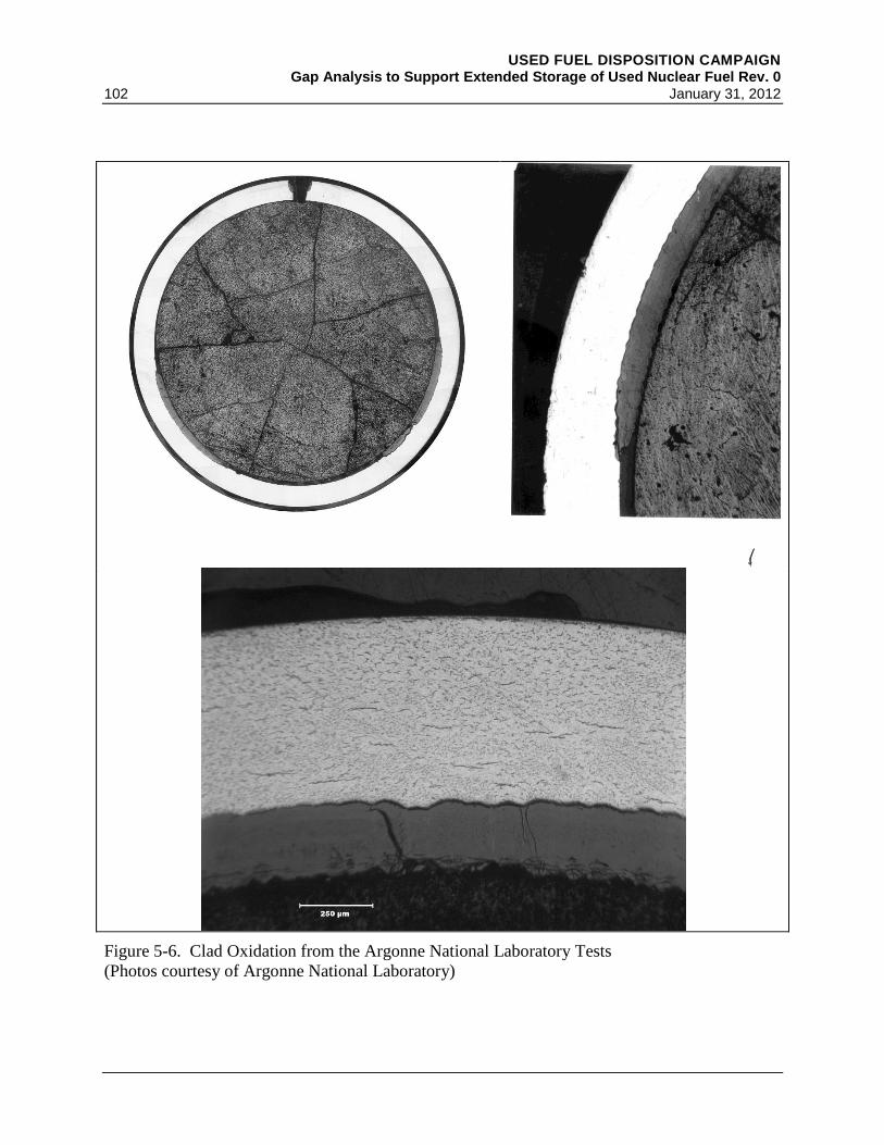
USED FUEL DISPOSITION CAMPAIGN Gap Analysis to Support Extended Storage of Used Nuclear Fuel Rev. 0
102 January 31, 2012
Figure 5-6. Clad Oxidation from the Argonne National Laboratory Tests
(Photos courtesy of Argonne National Laboratory)

USED FUEL DISPOSITION CAMPAIGN Gap Analysis to Support Extended Storage of Used Nuclear Fuel Rev. 0 January 31, 2012 103
5.2.3.8 Wet Corrosion
Literature Search and Degradation Mechanism Analysis
Wet corrosion can only occur when water is present within the DCSS. There will always be
residual water remaining after even a successful drying procedure. The free water should be
minimal, but there can be physisorbed and chemisorbed water present, especially in the oxide
and crud layers on the cladding and in any breached rods. The amount of water will determine
what, if any, of the wet corrosion mechanisms are applicable. As such, assuming drying occurs
as proposed, it is assumed that the water remaining is insufficient to have any real effect. The
drying investigations (Section 4.2) have been assigned a High priority to provide information to
facilitate the analyses for cladding wet corrosion mechanisms. These mechanisms include:
general corrosion, pitting corrosion, SCC, crevice corrosion, galvanic corrosion and can be
facilitated by water-logged rods and radiolysis of air and water. All of these mechanisms will be
treated together unless the drying investigation results indicate that enough water is present for
any of these mechanisms to be of concern. Two of the factors demonstrating the concern with
remaining water are briefly discussed here.
Kohli et al. (1985) showed that the bulk of water in a waterlogged rod was released not just
during vacuum drying, but vacuum drying with the temperature at 100°C. Because of decay
heat, the fuel in most DCSS drying can approach the NRC recommendation of 400°C peak clad
temperature. It would be expected that most water would be removed during drying. However,
the reactor-induced breaches in the rods tested by Kohli et al. were relatively large and could be
seen with visual examination. In addition, “holes (~3.0 mm in diameter) were drilled in the
plenum region of each rod to release any water that may have been trapped in the plenum.”
Multiple, large defects allow water to be released and have less chance of icing up (sealing)
during vacuum drying. Even with these multiple, large defects, the rods continued to outgas for
about 1000 hours at 325°C. Waterlogged rods would be capable of producing the high relative
humidity at temperatures higher than 175°C and could result in clad unzipping as was observed
in the ANL tests (BSC 2004b).
Radiolysis of water can result in production of oxygen or highly oxidizing species (e.g., OH∙ or
H2O2) that can then corrode fuel, cladding, or cask internals. However, water is limited to what
may be left in a cask after vacuum drying (as free-, chemisorbed- or physisorbed-water) or in
waterlogged rods. Radiolysis of nitrogen (either from air ingress or mistaken backfill) can result
in the production of very aggressive oxidants such as nitric acid, even though concentrations may
be low (Sunder and Miller 1996; Delegard et al. 2009). Water reactions could produce hydrogen
that could react with the cladding resulting in embrittlement.
Research and Development Priority
Data Needs: As part of the drying task, more realistic calculations of how much water may
remain in the DCSS and the forms it might be in will be performed. This will include the
possible contribution from water-logged rods, which includes water in bottom of the water tubes
of older Westinghouse assembly designs.

USED FUEL DISPOSITION CAMPAIGN Gap Analysis to Support Extended Storage of Used Nuclear Fuel Rev. 0
104 January 31, 2012
Regulatory Considerations: During storage, the regulations and guidance imply that maintaining
the clad in the same state as it was loaded, including preventing gross degradation, is important
to meeting the retrievability requirement. Wet corrosion mechanisms may be ruled out in
contributing to degradation if it can be shown there is too little water remaining to be an issue.
Likelihood of Occurrence: It seems unlikely that sufficient quantities of water remain after
drying to promote wet corrosion. This will be revisited based upon the results of the drying task.
Consequences: Wet corrosion mechanisms could contribute to rod failure.
Remediation: There is no remediation for wet corrosion during storage.
Cost and Operations: If additional rods fail and break, the cost and complication to operations
would be significant.
Future Waste Management Strategies: Rod failure due to wet corrosion would complicate
loading options and remove cladding credit for future waste management strategies.
Therefore, additional research and development for evaluating clad wet corrosion is assigned a
Low priority until results of the drying studies are known.
5.2.3.9 Creep
Literature Search and Degradation Mechanism Analysis
The main driving force for cladding creep is the hoop stress caused by internal rod pressure,
which will decrease over time as the temperature decreases and the rod volume increases. The
hoop stresses are between 30 and 200 MPa for a 17×17 PWR fuel rod and 12 to 130 MPa for a
10×10 BWR rod at 400 °C. Creep is considered self-limiting; as creep increases, the internal
volume of the rod increases which results in the pressure decreasing and reducing the hoop
stress. Clad creep to failure typically results in a very small defect (pinhole or hairline crack)
that will release the internal gas, including fission gases. However, of equal or more importance
is if creep, which thins the wall thickness of the cladding, is sufficient to make the rods
susceptible to breaking at these thin points during handling or transportation.
Examination of UNF with burnups of up to 36 GWd/MTU that had been stored for
approximately 15 years in a CASTOR V/21 dry storage cask as part of the DCSCP showed that
the maximum creep was no more than 0.1% (EPRI 2002a). However, no rod profilometry data
was available for the rods prior to storage, so this conclusion is based on comparison to as-
fabricated data and not comparison of actual pre-storage experimental data. Note that the
diameter of cladding can change significantly in-reactor due to creepdown and fuel swelling,
therefore, the use of as-fabricated data would not be able to see creep strains of 1% or smaller in
these fuel rods. In addition, the low burnup fuel in this test had fuel rod pressures that can be a
factor of 2 to 7 lower than those in limiting high burnup rods in today’s aggressive operating
plants.
USED FUEL DISPOSITION CAMPAIGN Gap Analysis to Support Extended Storage of Used Nuclear Fuel Rev. 0 January 31, 2012 105
In creep tests at temperatures from 250–400°C of Zircaloy cladding irradiated up to a burnup of
64 GWd/MTU, no failures have been observed below 2% strain (Goll et al. 2001; EPRI 2002b).
However, all test durations were between a few days to at most 100 days (2400 hours). In
addition, those tests above 1% strain were all performed near 400°C, where annealing improves
cladding ductility. An exception is the failure experienced by Tsai and Billone (2003) when a
high burnup cladding cooled from 400°C at 190 MPa hoop stress, although that failure occurred
at the end caps. Examination revealed that a significant amount of hydride reorientation had
occurred.
It is often stated that at temperatures below 300°C, creep may be considered to be immeasurably
slow and is not a factor in extended storage under normal operation (EPRI 2002b). However,
there are multiple mechanisms for cladding creep (Murty 2000). These mechanisms come into
play under different temperature and stress regimes. Murty warns that “blind extrapolations of
the short-term, high stress data to low stresses and temperatures could lead to nonconservative
predictions of the creep rates, creep strains, and lifetimes due to the dominance of viscous creep
mechanisms, such as Nabarro-Herring, Coble, and Harper-Dorn creep at low stresses”
(Murty 2000). Chin et al. (1986) has created a deformation and fracture map that predicts creep
failure mechanisms for Zircaloy cladding within the different temperature and stress regimes but
the majority of the data used for this mapping was from non-irradiated cladding. This
deformation and fracture map was then incorporated into the DATING computer code for
predicting cladding creep and rupture in UNF (Simonen and Gilbert 1988). This creep and
rupture model/code was updated later based on a much larger amount of creep and rupture data
from unirradiated Zry-4 CWSRA and Zry-2 RXA cladding and a much smaller amount of data
from irradiated cladding (Gilbert et al. 2002).
The DATING code has been verified against a small amount of creep data from small test
specimens (primarily pressurized tubes), however, further creep and rupture data are needed near
the hoop stresses and temperatures expected for storage of high burnup fuel rods with Zry-4
CWSRA, Zry-2 RXA, ZIRLO™ CWSRA, ZIRLO™ PRXA, and M5®
cladding types. It should
be noted that creep data from short pressurized irradiated tubes cut from full sized high burnup
fuel rods are the most prototypical for fuel cladding creep in storage. This is because the stresses
in storage are due to internal rod pressures that result in biaxial stresses, pressurized creep test
specimens also result in biaxial stresses. Other creep tests with ring or axial tensile specimens
will result in uniaxial stresses that are not prototypic of those experienced in storage.
Another potential source of clad strain, regardless of internal pressure, results from the fuel-clad
bond. As discussed in Section 5.1.3.2, fuel pellet hourglass swelling and clad creepdown during
reactor operations can lead to “bambooing,” which may not be visible, but there is more strain at
the pellet-pellet interfaces. This strain would be present even at low temperatures and after the
rod has been depressurized due to a breach. While the strain is obviously much lower than the
strain from internal gas pressure, it must be analyzed to see if this strain contributes to creep for
some of the low strain mechanisms discussed by Murty (2000).
Finally, the contribution of oxide and crud layers and hydride concentration and orientation on
creep behavior needs to be better determined.

USED FUEL DISPOSITION CAMPAIGN Gap Analysis to Support Extended Storage of Used Nuclear Fuel Rev. 0
106 January 31, 2012
Research and Development Priority
Data Needs: Long-term low temperature (<400°C) data are necessary, especially on high burnup
fuels and newer clad alloys. The effects of oxide and crud layers as well as the hydride
concentration and orientation on creep need to be determined. Advanced modeling and
simulation to determine the effects of low strain mechanisms over the time periods of extended
storage should be performed.
Regulatory Considerations: During storage, the regulations and guidance imply that maintaining
the clad in the same state as it was loaded, including preventing gross degradation, is important
to meeting the retrievability requirement.
Likelihood of Occurrence: While it seems clear that the traditional high temperature, high strain
creep mechanism will be limited during extended storage, it is unclear if low temperature, low-
strain mechanisms will be operative. However, creep to failure is only a minor issue, creep such
that the cladding breaks during handling or transportation is more of a concern.
Consequences: Creep to failure will typically result in small defects that release the fission gas
inventory and could expose the fuel to an oxidizing environment. Creep could contribute to rod
failure, especially during handling and transportation.
Remediation: There is no remediation for creep during storage.
Cost and Operations: If additional rods fail and break, the cost and complication to operations
would be significant.
Future Waste Management Strategies: Rod failure due to creep would complicate loading
options and remove cladding credit for future waste management strategies.
Therefore, additional research and development for evaluating clad creep is assigned a Medium
priority.

USED FUEL DISPOSITION CAMPAIGN Gap Analysis to Support Extended Storage of Used Nuclear Fuel Rev. 0 January 31, 2012 107
5.2.4 Cladding Summary Table
Table 5-2. Degradation Mechanisms That Could Impact the Performance of the Cladding
Stressor Degradation Mechanism
Influenced by
Extended Storage or
Higher Burnup
Additional
Data Needed
Importance
of R&D
Thermal Annealing of radiation
damage Yes Yes Medium
Metal fatigue caused by
temperature fluctuations Yes Yes Low
Phase change No Yes Low
Chemical Emissivity changes No Yes Low
H2 effects: embrittlement
and reorientation Yes Yes High
H2 effects: delayed hydride
cracking Yes Yes High
Oxidation Yes Yes Medium
Wet corrosion No Yes Low
Mechanical Creep Yes Yes Medium
5.2.5 Approach to Closing Cladding Gaps
Very little, if any, data are publicly available on the newer cladding alloys and on high burnup
cladding. Experimental work will be performed to obtain these data and to obtain additional
information to address the numerous disagreements regarding cladding behavior, such as
whether low-temperature mechanisms (e.g., for DHC, annealing, and creep) are important over
extended storage. Most international programs are not yet addressing this data gap and the
UFDC will be a primary source of data. In addition to testing, a rigorous modeling and
simulation program is necessary, especially since obtaining data at low temperatures may not
produce results soon enough to develop models. These models will be validated when compared
against data obtained from the engineering-scale demonstration being investigated by the UFDC.
One of the primary needs is to establish the link between behavior and performance of
unirradiated cladding and actual irradiated cladding. This need will be met through both testing
and modeling as part of this program and in collaboration with university partners under NEUP.
The more realistic temperature profiles to be obtained by modeling under the cross-cutting issues
and testing and monitoring as part of the engineering-scale demonstration program are vital to
predicting cladding behavior during extended storage and subsequent transportation.
5.3 Assembly Hardware
5.3.1 Introduction
The primary components of fuel assembly hardware that serve a safety function for dry storage
of used nuclear fuel are grid spacers, guide tubes (PWR assemblies only), and assembly channels
(BWR assemblies only). There is other hardware connected to these components to lend

USED FUEL DISPOSITION CAMPAIGN Gap Analysis to Support Extended Storage of Used Nuclear Fuel Rev. 0
108 January 31, 2012
structural support such as tie plates, spacer springs, tie rods, and nozzles. Assembly hardware
includes a variety of designs, materials of construction, and types of connections that continue to
evolve.
There are several (8+) grid spacers in a typical fuel assembly. Grid spacers are composed of a
zirconium alloy similar to the cladding, Inconel®, or both. The construction of grid spacers
includes straps and springs to maintain the spacing between fuel rods, control rod vibration, and
provide lateral support. Springs made of Inconel® have low stress relaxation rates; whereas
springs made of zirconium alloys have higher stress relaxation rates with irradiation. Generally,
zirconium alloys are used in the intermediate grid spacers whereas Inconel® is used for the top
and bottom grid spacers. However, some assembly designs use Inconel® in the intermediate grid
spacers, and others use a zirconium alloy for all the grid spacers including the top and bottom
ones.
PWR fuel assemblies typically contain 5 to 25 guide and instrumentation tubes. They are
composed of a zirconium alloy similar to the cladding. Generally, guide tube walls are slightly
thinner than the cladding, whereas the instrumentation tube walls are slightly thicker.
Instrumentation tubes could also be “dimpled” on the inside wall to allow for centering of small-
diameter probes. Guide and instrumentation tubes are attached to the top and bottom nozzles and
the spacer grids and provide axial structural support.
BWR fuel assemblies are surrounded by a channel made of a zirconium alloy similar to the
cladding but significantly thicker, attached to the top and bottom tie plates. Channels increase
the structural robustness of BWR fuel assemblies. Although dry storage casks accommodate
both channeled or unchanneled BWR fuel assemblies, most BWR assemblies are stored
channeled.
5.3.2 Analysis of Safety Functions
Degradation of assembly hardware affects the five storage safety functional areas as follows:
Retrievability: Significant degradation of assembly hardware could impact retrievability of the
fuel assemblies, necessitating costly design feature and radiologically taxing operations to
comply with the retrieval requirement with normal means as clarified in SFST-ISG-2.
Thermal Performance: Degradation of a sufficient number of grid spacers that results in
significant changes in fuel pin pitch could directly impact thermal performance and could
potentially create local hot spots.
Radiological Protection: No impact.
Confinement: No impact.
Subcriticality: Because the basis for maintaining subcriticality during storage is moderator
control provided by the container, and indirectly by the overpack (by protecting the container),

USED FUEL DISPOSITION CAMPAIGN Gap Analysis to Support Extended Storage of Used Nuclear Fuel Rev. 0 January 31, 2012 109
fuel assembly hardware does not provide a subcriticality function during storage. Fuel assembly
hardware provides a subcriticality function during flooded loading and retrieval operations by
maintaining the fuel pin pitch.
Based on the four potential stressors (thermal, radiation, chemical, and mechanical), the
identified failure mechanisms during normal or off-normal conditions that could result in
degradation of fuel assembly hardware are creep, wet corrosion, hydriding effects, and metal
fatigue caused by temperature fluctuations.
It is important to note that in-reactor service substantially alters the condition and material
properties of assembly hardware. These altered material properties establish the initial
conditions for dry storage. The most significant changes to assembly hardware condition and
material properties due to reactor service are structural growth, creep, stress relaxation, corrosion
and hydriding.
For BWR fuel channels, performance is mainly influenced by bulging, bow, and corrosion as
well as volume expansion due to zirconium hydride formation. Extent of channel bow depends
on burnup and flux gradients. Corrosion and hydriding of Zr alloys in BWR fuel can differ quite
significantly from reactor to reactor for unknown reasons. Further, the models that can be
applied today to estimate the contributions from corrosion and hydriding to growth are still very
questionable. In the last few years, increasing occurrence of significant control blade friction
events due to control blade induced shadow corrosion and channel bow have been observed. The
reason for the late hydrogen pickup under the shadow corrosion, the influence of material
condition, and water chemistry influences are not well understood.
Corrosion of Zr alloys used for PWR structural components such as guide tubes and spacers
depends on temperature, material composition, and condition. The behavior and the design of
PWR guide tubes govern the fuel assembly growth and bow behavior. Meanwhile, many data on
growth of fuel assemblies with Zircaloy-4 guide tubes have been reported. Evaluation of these
data indicates a large scatter at low to moderate burnup, an acceleration of the growth at high
burnups, and very large variations of the high burnup acceleration of growth. Growth
contributions also come from oxide layer formation induced irradiation creep and volume change
due to hydrogen pickup.
Grid-to-rod fretting has significantly contributed to PWR fuel defects in the past, and with
improved assembly designs, has recently become rare. No grid-to-rod fretting defects have been
reported for U.S. BWR fuel (Cox et al. 2006). Although fretting is an important degradation
mechanisms for assembly hardware and fuel cladding during reactor operations, it is not a
degradation mechanism during dry storage. Fretting contributes to the designation of a fuel
assembly (damaged or undamaged) and establishes the assembly initial condition for dry storage.
Degradation of a few grid spacers or guide tubes may not constitute a failure during normal and
off-normal conditions if enough spacers and guide tubes remain intact to hold the fuel pins and
maintain axial support. However, their performance may no longer be acceptable under design
basis accidents.
USED FUEL DISPOSITION CAMPAIGN Gap Analysis to Support Extended Storage of Used Nuclear Fuel Rev. 0
110 January 31, 2012
Table 5-3 in Section 5.3.4 provides the results of the assembly hardware degradation
mechanisms analysis.
Importance of System to Licensing: Because assembly hardware is essential for retrievability
and for demonstrating subcriticality for wet loading and retrieval operations as well as all
conditions of transport, its importance to licensing is High.
5.3.3 Discussion of Selected Assembly Hardware Issues
Degradation mechanisms for assembly hardware during extended dry storage and additional
research and development needs are discussed and prioritized in this section. NWTRB (2010)
does not discuss degradation mechanisms of assembly hardware during extended storage. The
primary discussion in NWTRB (2010) regarding assembly hardware is related to fretting.
Although fretting is an important degradation mechanisms for assembly hardware and fuel
cladding during reactor operations, it is not a degradation mechanism during dry storage.
5.3.3.1 Creep
Literature Search and Degradation Mechanism Analysis
Although grids spacers, guide tubes, and channels are made of materials that could be subject to
creep at normal or off-normal temperatures during dry storage, they are not load bearing, with
the exception of the distributed weight of the fuel pins on the grid spacers and guide tubes.
Unlike cladding, there is no gas pressure acting upon guide tubes. In addition, as the fuel ages,
the temperature decreases and could potentially drop below the creep threshold; however, low-
temperature low-stress creep must be considered and properly evaluated. Therefore, due to lack
of significant stresses, creep is not expected to be a degradation mechanism for assembly
hardware. However, the weight of the assembly in a horizontal position for long periods could
cause limited creep of guide tubes and relaxation of the grid spacer springs, allowing the rods
more lateral movement when handled or moved. Nevertheless, even with allowed movement of
the rods, they are expected to remain in place, with any movement or displacement limited by the
available space between the pins and bottom nozzles and tie plates.
Research and Development Priority
Data Needs: Additional data may be needed to evaluate the extent of creep on the guide tubes
and grid spacer springs and straps as a function of extended storage.
Regulatory Considerations: The additional data would support the subcriticality requirement and
thermal performance function for wet retrieval and transportation operations by demonstrating
that the fuel pin pitch is maintained. The additional data would also support the retrievability
requirement by demonstrating that guide tubes maintain their structural integrity.
Likelihood of Occurrence: Creep will likely result in relaxation of grid spacer springs but will
likely not impact straps or guide tubes.

USED FUEL DISPOSITION CAMPAIGN Gap Analysis to Support Extended Storage of Used Nuclear Fuel Rev. 0 January 31, 2012 111
Consequences: Relaxation of grid spacer springs could have a very minor effect on the fuel pin
pitch, potentially slightly increasing the reactivity of the fuel assemblies for flooded
configurations.
Remediation: The effects of creep on guide tubes and grid spacer springs cannot be remediated.
Cost and Operations: Creep is not expected to result in costly designs or operational difficulties.
Future Waste Management Strategies: Creep is not expected to limit or complicate future waste
management strategy.
Therefore, additional research and development for evaluating creep of assembly hardware is
assigned a Low priority. This priority may change if it is concluded that low-temperature low-
strain cladding creep as discussed in Section 5.2.3.9 is a realizable cladding degradation
mechanism during extended storage.
5.3.3.2 Metal Fatigue Caused by Temperature Fluctuations
Literature Search and Degradation Mechanism Analysis
With longer storage times, there are more summer–winter temperature fluctuations and increased
likelihood of extreme weather conditions. However, the temperature of the assembly hardware
is not expected to be significantly impacted by those fluctuations, given the relatively large heat
capacity of storage systems and the fact that assembly hardware is an integral component of the
heat-generating fuel. Although temperature fluctuations may result in changes in material
properties of assembly hardware, they are not likely to result in a failure. Material property
changes are important in evaluating assembly hardware performance during design basis
accidents and transportation hypothetical accident conditions.
Research and Development Priority
Data Needs: Analyses of temperature profiles (axial and radial) of low and high burnup fuels
over the entire period of dry storage, taking into account normal and off-normal environmental
conditions, are needed to determine the extent of metal fatigue caused by temperature
fluctuations.
Likelihood of Occurrence: It is unlikely that temperature fluctuations will result in failure or
weakening of fuel assembly hardware.
Regulatory Considerations: The additional data would support the subcriticality requirement and
thermal performance function for design basis accidents and transportation hypothetical accident
conditions by demonstrating that the fuel pin pitch is maintained. The additional data would also
support the retrievability requirement by demonstrating that guide tubes maintain their structural
integrity.
USED FUEL DISPOSITION CAMPAIGN Gap Analysis to Support Extended Storage of Used Nuclear Fuel Rev. 0
112 January 31, 2012
Consequences: Metal fatigue of assembly hardware would not lead to failure during storage
conditions, but may result in unacceptable performance during storage design basis accidents and
transportation hypothetical accident conditions such that the subcriticality bases would be
changed and fuel retrievability might be complicated.
Remediation: The effects of metal fatigue on assembly hardware cannot be remediated.
Cost and Operations: Metal fatigue of assembly hardware is not expected to result in costly
designs or operational difficulties.
Future Waste Management Strategies: Metal fatigue is not expected to limit or complicate future
waste management strategy.
Therefore, additional research and development for evaluating assembly hardware fatigue caused
by temperature fluctuations is assigned a Low priority.
5.3.3.3 Corrosion and Stress Corrosion Cracking
Literature Search and Degradation Mechanism Analysis
Assembly hardware is subject to corrosion during the off-normal condition of moisture presence
inside the canisters due to inadequate drying or waterlogged rods. The rate and extent of
corrosion are expected to be highest during the initial period of storage. Once the moisture has
been expended, wet corrosion would stop. Therefore, due to the lower temperatures and absence
of moisture during extended storage, wet corrosion is expected be a minor contributor to
assembly hardware degradation for extended storage; however, its impact during the initial
period of dry storage needs to be better evaluated.
Corrosion that resulted in separation of the top nozzle for fuel assemblies and subsequent drop
was experienced for some Westinghouse fuel assemblies manufactured in the 1980s. These
assemblies contained assembly hardware materials that were susceptible to intergranular stress-
corrosion cracking. Licensees have utilized several “normal” handling methods, such as special
handling tools or an instrument tube tie rod, to load these assemblies into dry storage, such that
the fuel was not considered damaged (EPRI 2010b, Section 7.3.4).
Therefore, assembly hardware could degrade sufficiently due to chemical stressors during reactor
operations to the point of failure, or it could have undetected incipient degradation that would
lead to failure during extended storage.
Research and Development Priority
Data Needs: Additional data are needed to evaluate the effect of corrosion and stress corrosion
cracking on assembly hardware early during dry storage.
Likelihood of Occurrence: Even though it is unlikely that corrosion and stress corrosion
cracking will impact assembly hardware during extended storage, its impact during the initial

USED FUEL DISPOSITION CAMPAIGN Gap Analysis to Support Extended Storage of Used Nuclear Fuel Rev. 0 January 31, 2012 113
period of storage needs to be better evaluated, with that evaluation establishing the initial
condition for extended storage.
Regulatory Considerations: The additional data would support the retrievability requirement by
demonstrating that the fuel assemblies can be handled with normal means.
Consequences: Corrosion and stress corrosion cracking of fuel assembly hardware would not
lead to failure during storage conditions but may result in complicating retrieval by necessitating
the use of special handling tools.
Remediation: The effects of corrosion and stress corrosion cracking on assembly hardware can
be remediated with the use of special handling tools.
Cost and Operations: Corrosion of assembly hardware has and might result in costly designs or
operational difficulties to facilitate fuel retrieval.
Future Waste Management Strategies: Corrosion of assembly hardware is not expected to limit
or complicate future waste management strategy.
Therefore, additional research and development for evaluating corrosion of assembly hardware is
assigned a Medium priority.
5.3.3.4 Hydriding Effects
Literature Search and Degradation Mechanism Analysis
Assembly hardware made from zirconium alloys is potentially subject to hydriding effects that
could reduce the material ductility and fracture toughness, particularly at lower temperatures,
which is especially important for extended storage once the fuel has cooled. However, unlike
cladding, there is no hoop stress for assembly hardware to cause hydride reorientation; therefore,
the impact of hydriding effects on assembly hardware is far less severe than for cladding.
Because there is limited load during storage on assembly hardware, it is unlikely that hydriding
will result in sufficient assembly hardware failure to impact any of the dry storage safety
functions during normal and off-normal conditions. However, material properties might change
such that the assembly hardware performance may not be acceptable for storage design basis
accidents and transportation hypothetical accident conditions.
Research and Development Priority
Data Needs: Additional data are needed to evaluate the effect of hydriding on the structural
properties of assembly hardware, particularly the guide tubes and grid straps.
Likelihood of Occurrence: Hydriding effects on assembly hardware will likely change the
material properties of assembly hardware, causing them to become more brittle, especially at the
lower temperatures for extended storage.

USED FUEL DISPOSITION CAMPAIGN Gap Analysis to Support Extended Storage of Used Nuclear Fuel Rev. 0
114 January 31, 2012
Regulatory Considerations: The additional data would support the subcriticality requirement and
thermal performance function for design basis accidents and transportation hypothetical accident
conditions by demonstrating that the fuel pin pitch is maintained.
Consequences: Hydriding effects on assembly hardware would not lead to failure during storage
conditions but may result in unacceptable performance for storage design basis accidents and
transportation hypothetical accident conditions such that the subcriticality and thermal bases
would be changed.
Remediation: The effects of hydriding on fuel assembly hardware cannot be remediated.
Cost and Operations: Hydriding of assembly hardware might result in costly designs or
operational difficulties to demonstrate compliance with thermal and subcriticality requirements
with alternate means (e.g., moderator exclusion).
Future Waste Management Strategies: Hydriding of assembly hardware could complicate the
transportation component of a future waste management strategy.
Therefore, additional research and development for evaluating the hydriding effect on assembly
hardware is assigned a Low priority.
5.3.4 Hardware Summary Table
Table 5-3. Degradation Mechanisms That Could Impact the Performance of the Grid Spacers
Stressor Degradation Mechanism
Influenced by
Extended Storage
or Higher Burnup
Additional
Data Needed
Importance
of R&D
Thermal and
Mechanical
Creep Yes Yes Low
Metal fatigue caused by
temperature fluctuations
Yes Yes Low
Chemical Corrosion and stress
corrosion cracking
Yes Yes Medium
Hydriding effects Yes Yes Low
5.3.5 Approach to Closing Assembly Hardware Gaps
No specific tests to evaluate effects of extended storage have been identified for fuel assembly
hardware, although some of the testing on Zircaloy cladding could apply to Zircaloy assembly
hardware components. As discussed in Section 5.3, the degradation mechanisms for assembly
hardware are not significantly exacerbated by extended dry storage. What caused the Medium
priority for research and development for assembly hardware is its importance for retrievability
and the fact that its conditions is not well characterized prior to dry storage.

USED FUEL DISPOSITION CAMPAIGN Gap Analysis to Support Extended Storage of Used Nuclear Fuel Rev. 0 January 31, 2012 115
To close assembly hardware data gaps, better inspection and characterization of assembly
hardware are needed prior to dry storage to establish its initial conditions. Once dry storage
stressors have been better quantified through the various analyses identified in this report,
including thermal modeling, drying efficiency, and radiation source terms, the condition of
assembly hardware as a function of extended storage can be evaluated.
5.4 Fuel Baskets
5.4.1 Introduction
The safety function of fuel baskets is to hold the fuel assemblies and neutron poisons in a set
geometry to meet the subcriticality requirement and thermal performance functions and to allow
for fuel loading and retrieval. Baskets are made from a variety of metals such as stainless steel,
carbon steel, and aluminum alloys and have both base metal and welds. Some basket materials,
such as Metamic, an aluminum-boron-carbide metal matrix composite, also serve as the neutron
poison material. The degradation mechanisms for these materials are discussed in Section 5.5.
5.4.2 Analysis of Safety Functions
Degradation of fuel baskets affects the five storage safety functional areas as follows:
Retrievability: Degradation of fuel baskets will have a direct impact on retrievability because
their degradation could mechanically hinder the removal of fuel assemblies from the basket
compartments.
Thermal Performance: Changes in fuel baskets physiochemical properties could impact heat
transfer within the containers. Therefore, there is potentially an impact on thermal performance
due to fuel basket degradation.
Radiological Protection: No impact.
Confinement: No impact.
Subcriticality: Because the basis for maintaining subcriticality during storage is moderator
control provided by the container, and indirectly by the overpack (by protecting the container),
fuel baskets do not provide a subcriticality function during storage. Fuel baskets provide a
subcriticality function during loading and wet retrieval operations and transportation by
maintaining the neutron poisons and required spacing between fuel assemblies.
For the retrieval function, fuel baskets can fail by expanding or deforming in a way that would
reduce the spacing between the fuel assemblies and basket walls. For the subcriticality safety
function, fuel baskets can fail by deforming in a way that would reduce the spacing between the
fuel assemblies, thus increasing neutron coupling. For thermal performance, the fuel baskets can
fail by reduced heat conduction properties.
USED FUEL DISPOSITION CAMPAIGN Gap Analysis to Support Extended Storage of Used Nuclear Fuel Rev. 0
116 January 31, 2012
Based on the four potential stressors (thermal, radiation, chemical, and mechanical), the
identified failure mechanisms during normal or off-normal conditions that could result in fuel
basket expansion or deformation are wet corrosion, creep, and metal fatigue caused by
temperature fluctuations.
The only degradation mechanism during normal or off-normal conditions that could result in
reduction of heat conduction properties of the fuel baskets is wet corrosion.
Small cracks in the welds may not degrade the performance of the fuel baskets safety functions
as long as the basket geometry is maintained. However, small cracks in the welds may weaken
the baskets sufficiently such that their performance may no longer be acceptable under storage
design basis accidents and transportation hypothetical accident conditions.
Table 5-4 in Section 5.4.4 provides the results of the fuel baskets degradation mechanisms
analysis.
Importance of System to Licensing: Because fuel baskets are essential for retrievability,
thermal performance and for demonstrating subcriticality for wet loading and retrieval operations
as well as all conditions of transport, their importance to licensing is High.
5.4.3 Discussion of Selected Basket Issues
Degradation mechanisms for fuel baskets during extended dry storage and additional research
and development needs are discussed and prioritized in this section. NWTRB (2010) does not
discuss degradation mechanisms of fuel baskets during extended storage.
5.4.3.1 Creep
Literature Search and Degradation Mechanism Analysis
Stainless steel and carbon steel basket components are not subject to creep at normal or off-
normal temperatures during dry storage. However, for aluminum, creep analysis should be
performed if any load-bearing aluminum components operate above approximately 93°C.
Because the cladding temperature may approach the 400°C limit during loading and normal
storage conditions (NUREG-1536, Section 8.4.9 [NRC 2010b]) be performed to determine when
the temperature of load-bearing aluminum components of fuel baskets drops below the creep
threshold. If necessary based on the results of the analysis, additional experimental data may
need to be acquired to determine the extent of aluminum creep during extended storage.
Regulatory Considerations: The analysis would determine the need for additional experimental
data. The additional experimental data, if needed to be acquired, would support the retrievability
requirement and subcriticality requirement during wet retrieval or transportation operations by
demonstrating that the fuel baskets are not expected to deform sufficiently to impact physical
retrieval of fuel assemblies or increase neutron coupling.

USED FUEL DISPOSITION CAMPAIGN Gap Analysis to Support Extended Storage of Used Nuclear Fuel Rev. 0 January 31, 2012 117
Likelihood of Occurrence: Significant creep of aluminum load-bearing basket materials is
unlikely, given the types of alloys used in construction of fuel baskets materials and the lower
temperatures during extended storage. In addition, the load during storage is minimal for vertical
casks and well distributed for horizontal casks.
Consequences: The consequences of creep are not expected to be significant enough to hinder
assembly removal or result in a substantial increase in system reactivity.
Remediation: Because fuel baskets are inside the sealed canisters, they cannot be remediated
without repackaging.
Cost and Operations: Creep of fuel baskets is not expected to result in costly designs or
operational difficulties.
Future Waste Management Strategies: Creep of fuel baskets is not expected to limit or
complicate future waste management strategy.
Therefore, additional research and development for evaluating creep of aluminum-based fuel
baskets is assigned a Low priority.
5.4.3.2 Metal Fatigue Caused by Temperature Fluctuations
Literature Search and Degradation Mechanism Analysis
With longer storage times, there are more summer–winter temperature fluctuations and increased
likelihood of extreme weather conditions. Fuel basket degradation influenced by the temperature
fluctuations may not necessarily impact any of the safety functions. One such mechanism
observed to impact the basket but not affect any of the safety functions is cracking of
nonstructural welds due to thermal expansion stresses. This process was observed by the
DCSCP (EPRI 2002a, p. I-2-20). The cracked welds appeared to be nonstructural and were
intended only to provide additional stability during loading and testing. EPRI concluded that the
cracks were not relevant to normal long-term storage and presented no adverse safety
implications on the cask or components to perform their safety functions during storage.
Research and Development Priority
Data Needs: An analysis needs to be performed to determine the extent of temperature
fluctuations as a function of extended dry storage and environmental conditions. If necessary
based on the results of the analysis, additional experimental data may need to be acquired to
determine the extent of metal fatigue and thermally induced failures of fuel baskets.
Regulatory Considerations: The analysis would determine the need for additional experimental
data. The additional experimental data, if needed to be acquired, would support the retrievability
requirement and subcriticality requirement during wet retrieval or transportation operations by
demonstrating that the fuel baskets are not expected to deform sufficiently to impact physical
retrieval of the fuel assemblies or increase neutron coupling.
USED FUEL DISPOSITION CAMPAIGN Gap Analysis to Support Extended Storage of Used Nuclear Fuel Rev. 0
118 January 31, 2012
Likelihood of Occurrence: Metal fatigue of load-bearing basket materials is unlikely, given the
lower temperatures during extended storage and the fact that temperature fluctuations of
components inside the storage systems, such as the baskets, are not expected to be large due to
the large thermal capacity of storage casks.
Consequences: The consequences of metal fatigue of the fuel baskets are not expected to be
significant enough to hinder assembly removal or result in a substantial increase in system
reactivity.
Remediation: Because fuel baskets are inside the sealed canisters, they cannot be remediated
without repackaging.
Cost and Operations: Metal fatigue of fuel baskets is not expected to result in costly designs or
operational difficulties.
Future Waste Management Strategies: Metal fatigue of fuel baskets is not expected to limit or
complicate future waste management strategy.
Therefore, additional research and development for evaluating metal fatigue caused by
temperature fluctuations of fuel baskets is assigned a Low priority.
5.4.3.3 Corrosion
Literature Search
Basket components are subject to corrosion during off-normal conditions if sufficient oxygen
and/or moisture is present inside the canisters due to inadequate drying or waterlogged rods. The
rate and extent of corrosion are expected to be highest for carbon steel and aluminum
components during the initial period of storage. Once the moisture has been expended, wet
corrosion would stop. Therefore, due to the lower temperatures and absence of moisture during
extended storage, wet corrosion is expected be a minor contributor to fuel basket component
degradation.
Research and Development Priority
Data Needs: An analysis needs to be performed to determine the extent of moisture present due
to inadequate drying or water-logged rods. If necessary based on the results of the analysis,
additional experimental data may need to be acquired to determine the extent of basket corrosion
during the initial and extended durations of dry storage.
Regulatory Considerations: The analysis would determine the need for additional experimental
data. The additional experimental data, if needed to be acquired, would provide the material and
structural properties of the fuel basket materials necessary to demonstrate subcriticality for wet
retrieval and transportation hypothetical accident conditions.

USED FUEL DISPOSITION CAMPAIGN Gap Analysis to Support Extended Storage of Used Nuclear Fuel Rev. 0 January 31, 2012 119
Likelihood of Occurrence: Corrosion of basket materials is unlikely during extended storage,
given that if oxygen or moisture remains after drying operations, any corrosion would take place
early during dry storage when temperatures are highest.
Consequences: The consequences of basket corrosion are expected to be minimal because of the
relatively small amount of moisture, if any, and significant amount of metal inside the cask.
Remediation: Because fuel baskets are inside the sealed canisters, they cannot be remediated
without repackaging.
Cost and Operations: Corrosion of fuel baskets is not expected to result in costly designs or
operational difficulties.
Future Waste Management Strategies: Corrosion of fuel baskets is not expected to limit or
complicate future waste management strategy.
Therefore, additional research and development for evaluating corrosion of fuel baskets is
assigned a Low priority.
5.4.4 Fuel Baskets Summary Table
Table 5-4. Degradation Mechanisms That Could Impact the Performance of Fuel Baskets
Stressor Degradation Mechanism
Influenced by
extended storage
or Higher Burnup
Additional
Data Needed
Importance
of R&D
Thermal and
Mechanical
Creep Yes Yes Low
Metal fatigue caused by
temperature fluctuations
Yes Yes Low
Chemical Corrosion Yes Yes Low
5.4.5 Approach to Closing Fuel Baskets Gaps
Because the fuel basket materials of concern are the same or similar to those that also serve as a
neutron poison, the models and tests needed to address the gaps for basket materials are covered
by those proposed for neutron poison materials discussed in Section 5.5.5.
5.5 Neutron Poisons
5.5.1 Introduction
The safety function of neutron poisons, in conjunction with the spacing provided by the fuel
baskets discussed in Section 5.4, is to maintain subcriticality for flooded configurations. Flooded
configurations are credible only during loading and, potentially, retrieval operations. Neutron
poisons are present in most, but not all, loaded or licensed dry storage casks. Pool-soluble boron
is credited for maintaining subcriticality for high-density PWR storage casks as well as casks that

USED FUEL DISPOSITION CAMPAIGN Gap Analysis to Support Extended Storage of Used Nuclear Fuel Rev. 0
120 January 31, 2012
do not contain neutron poisons. Even for low-density storage casks that contain neutron poisons,
soluble boron can be credited along with the fixed poisons and flux traps to allow for loading
fuel assemblies with higher reactivity.
Neutron poisons, integral to the fuel, burn out within the first few gigawatt-days of exposure and
are not credited in the criticality safety analysis. Although the regulation allows for crediting
discrete burnable poison rods or used control rods inserted in the guide tubes of some assemblies,
they are generally not credited for more than their moderator displacement characteristics due to
the onerous required characterization. However, they must be taken into account in the source
term evaluation for radiation protection.
Neutron poisons used in dry storage casks are made primarily from borated aluminum alloys,
metal matrix composites, borated stainless steel materials, and aluminum boride carbon cermets
(EPRI 2005).
Borated Aluminum Alloys
Ceradyne has two aluminum boron alloys for used nuclear fuel cask applications based on an
aluminum 1100 alloy matrix and an aluminum 6351 alloy matrix. The 1100 alloy is produced
with boron loading ranging from 1.25 wt% to 4.5 wt% with boron enriched to ≥ 95% in 10
B. In
the 6351 alloy, the maximum boron loading is limited to 2.0 wt%. The 1100 alloy product is
intended for nonstructural applications. For applications requiring a structural alloy, the
6351 aluminum boron product is preferred. These alloys have a density near the maximum
theoretical density with little or no internal porosity.
Metal Matrix Composites
The most common metal matrix composite neutron poisons for use in storage applications are
MetamicTM
and BORTECTM
. The B4C loading for these materials ranges between 15 wt% to
45 wt%. Similar to alloys, metal matrix composites have near theoretical density with minimal
to no porosity. A metal matrix composite is produced from an ingot that is formed either by
casting or via a powder metallurgical process under high pressure with or without elevated
temperature. This produces an ingot that is close to maximum theoretical density and a final
rolled plate that is void of internal porosity.
Borated Stainless Steel Materials
NeutroSorb™ alloys and Neutronit™ are the two main borated stainless steel absorbers that have
been used in storage systems. Both are defined by ASTM-A887-89 Grade A that specifies eight
alloys with boron content spanning the range of 0.20 wt% boron to 2.35 wt% boron. Two grades
are defined—Grade “A” and Grade “B”—depending on the uniformity of the boride dispersion
and microstructure. Grade “A” alloys possess improved mechanical properties due to the finer
and more uniformly distributed borides that are present compared to the Grade “B” alloys.

USED FUEL DISPOSITION CAMPAIGN Gap Analysis to Support Extended Storage of Used Nuclear Fuel Rev. 0 January 31, 2012 121
NeutroSorb alloys are produced based on a powdered metallurgical process. NeutroSorb Plus™
is produced with argon atomized alloy and meets the requirements of ASTM A887 Grade A. A
Grade B product is produced in a similar process with nitrogen atomized alloy.
Neutronit™ is an ASTM-A887 Grade B material. The material is produced by a traditional
vacuum melt, cast/wrought method followed by either hot or cold rolling and heat treatment.
The upper limit for alloying boron into stainless steel using this production method is 1.9 wt%.
Custom alloys are available for additional corrosion resistance. One contains molybdenum, and
a second has increased chromium content.
Aluminum Boron Carbide Cermets
Ceradyne produces BORAL™, which is the most commonly used neutron absorber for dry
storage applications. BORAL™ is a hot-rolled composite sheet consisting of 1) a core of
uniformly mixed and distributed boron carbide and alloy 1100 aluminum particles; and 2) a
surface cladding, on both sides of the core, serving as a solid barrier. BORAL™ has been
produced with the core containing anywhere between 35 wt% and 65 wt% B4C.
Cermets, unlike metal matrix composites and borated alloys, have less than theoretical density.
Cermets are produced from an ingot that is an aluminum-clad container filled with a
homogenous mixture of boron carbide powder and atomized aluminum powder. When the ingot
is heated and subsequently hot-rolled to plate form, the aluminum particles sinter at the rolling
temperature and under the pressure caused by the rolling process. However, the sintering
process results in a core that contains some porosity. For dry storage applications, aluminum
boron carbide cermets are encased in aluminum or steel cladding and cannot be used as structural
load-bearing components.
5.5.2 Analysis of Safety Functions
Degradation of neutron poisons affects the five storage safety functional areas as follows:
Retrievability: Degradation of neutron poisons could mechanically hinder the removal of the
fuel assemblies from the basket compartments, thus impacting retrievability.
Thermal Performance: Changes in neutron poison physiochemical properties could impact heat
transfer within the containers. Therefore, there is potentially an impact on thermal performance
due to neutron poisons degradation.
Radiological Protection: No impact.
Confinement: No impact.
Subcriticality: Because the basis for maintaining subcriticality during storage is moderator
control provided by the container and indirectly by the overpack (by protecting the container),
neutron poisons do not provide a subcriticality function during storage. Neutron poisons provide

USED FUEL DISPOSITION CAMPAIGN Gap Analysis to Support Extended Storage of Used Nuclear Fuel Rev. 0
122 January 31, 2012
a subcriticality function during wet loading and retrieval operations. For transportable canisters
and casks, neutron poisons provide a subcriticality function to meet transportation requirements.
For the thermal performance function, neutron poisons could fail by reduced heat conduction and
emissivity characteristics. For the retrievability function, neutron poisons could fail by bending
and swelling. For the subcriticality function, neutron poisons could fail by poison isotope
density reduction and by reduction in the gap between the fuel assemblies. Based on the four
potential stressors (thermal, radiation, chemical, and mechanical), the identified degradation
mechanisms for neutron poisons are thermal aging effects, thermal and radiation embrittlement
and cracking, metal fatigue caused by temperature fluctuations, creep, poison burnup, and wet
corrosion (blistering). Table 5-5 in Section 5.5.4 provides the results of the degradation
mechanisms analysis.
Importance of System to Licensing: Because neutron poisons are essential for demonstrating
subcriticality for wet loading and retrieval operations as well as all conditions of transport, their
importance to licensing is High.
5.5.3 Discussion of Selected Neutron Poison Issues
Degradation mechanisms for neutron poisons during extended dry storage and additional
research and development needs are discussed and prioritized in this section. NWTRB (2010)
discusses two types of neutron poisons degradation mechanisms and concludes that significant
degradation of the neutron poison panels is not possible if the inert gas (helium) atmosphere
inside the container is maintained and if consumption of boron by neutrons produced by
spontaneous fission or by (α,n) reactions is insignificant.
5.5.3.1 Thermal Aging Effects
Literature Search and Degradation Mechanism Analysis
All metals undergo changes in their mechanical properties when exposed to elevated
temperatures. Aluminum-based materials typically exhibit a decline in properties at
temperatures above about 93°C. These property changes are generally reversible after exposure
to short-duration moderate temperature excursions; however, long-duration elevated temperature
exposure generally results in permanent decrease of mechanical properties such as yield and
tensile strength. Heat-treated alloys are more susceptible to changes in material properties than
non-heat treated alloys.
To determine the long-term effects of thermal aging on Metamic-HT™, a metal matrix
composite neutron poison material, 30 samples were exposed to temperatures above 300°C to
age the material in an accelerated fashion. The accelerated aging technique was intended to
duplicate on a faster time scale the metallurgical and physical property changes that would occur
in the material under design conditions. This accelerated testing was done by exposing the
material to a higher temperature (for a shorter period) and using a mathematical model to equate
this accelerated “aging” process to a lower-temperature, longer-duration exposure as it would
occur in normal service. After thermal aging, the samples were tested and compared to unaged
USED FUEL DISPOSITION CAMPAIGN Gap Analysis to Support Extended Storage of Used Nuclear Fuel Rev. 0 January 31, 2012 123
samples to determine if any permanent changes occurred to the material properties. Aged
samples did exhibit some small changes in properties when compared to unaged (room
temperature) samples, but these changes were judged to be minor. Tensile and yield strength
values dropped about 2%–4%. The Charpy impact strength was virtually unchanged. It was
concluded that this is a unique response for this Metamic-HT™ material, which is not heat
treated (NRC 2009b, Section 2.2.2).
Research and Development Priority
Data Needs: Additional data are needed to evaluate the effects of thermal aging on the
mechanical properties of the various load-bearing neutron poison materials, particularly heat-
treated materials.
Regulatory Considerations: The additional data would support the subcriticality requirements
for wet retrieval and transportation operations.
Likelihood of Occurrence: Thermal aging effects on load-bearing neutron poisons are
potentially likely for heat-treated aluminum-based neutron poison materials.
Consequences: The consequences of thermal aging effects on neutron poisons are potentially
significant such that the poison material structural properties would not survive the loads of
storage design basis accidents and transportation hypothetical accident conditions.
Remediation: Because neutron poisons are inside the sealed canisters, they cannot be remediated
without repackaging.
Cost and Operations: Thermal aging effects on neutron poisons could result in costly designs or
operational difficulties.
Future Waste Management Strategies: Thermal aging effects of neutron poisons are not
expected to limit or complicate future waste management strategy.
Therefore, additional research and development for evaluating thermal aging effects of neutron
poisons is assigned a Medium priority.
5.5.3.2 Thermal and Radiation Embrittlement and Cracking
Literature Search and Degradation Mechanism Analysis
Thermal, radiation, and mechanical stresses and subsequent cracking could reduce the efficacy of
neutron poisons by allowing for neutron streaming between fuel assemblies. However, thermal
embrittlement is not expected to worsen for longer storage times due to decreasing temperature.
Neutron and gamma radiation testing on various neutron absorber materials (EPRI 2005)
concluded that material properties do not change, even under irradiation levels that far exceed
those expected for 20–60 years of dry storage conditions. Radiation source terms decrease
significantly with extended storage.
USED FUEL DISPOSITION CAMPAIGN Gap Analysis to Support Extended Storage of Used Nuclear Fuel Rev. 0
124 January 31, 2012
Neutron poison materials that could be susceptible to such a degradation mechanism are encased
inside steel or aluminum alloy; therefore, such degradation would not cause any loss of the
poison material, although some cracking might occur. Neutron poisons that are not encased are
more structurally sound, with characteristics similar to aluminum alloy 6351 (EPRI 2005,
Section 6.2.1). The lower temperatures and lower radiation levels during extended storage are
not expected to degrade their performance.
Research and Development Priority
Data Needs: Additional data are needed to evaluate effect of thermal and radiation
embrittlement and cracking on neutron poisons, particularly the encased cermet types of
materials, which tend to have low ductility. The extent of the data needed is to evaluate the
reactivity penalty associated with the presence of cracks if any develop.
Regulatory Considerations: The additional data would support the subcriticality requirement for
wet retrieval and transportation operations by demonstrating continued efficacy of the neutron
poisons.
Likelihood of Occurrence: Embrittlement and cracking are potentially likely for cermet-type
neutron poison materials and unlikely for metal matrix composites or alloys.
Consequences: The consequences of embrittlement and cracking of neutron poisons are limited
to reducing the neutron poison efficacy. Unless the poison material relocates, which is unlikely
for encased cermet neutron poison materials susceptible to this degradation mechanism, the
reactivity increase due to the reduced neutron poisons efficacy is not expected to be large.
Remediation: Because neutron poisons are inside the sealed canisters, they cannot be remediated
without repackaging.
Cost and Operations: Embrittlement and cracking of neutron poisons could result in costly
designs or operational difficulties.
Future Waste Management Strategies: Embrittlement and cracking of neutron poisons are not
expected to limit or complicate future waste management strategy.
Therefore, additional research and development for evaluating thermal and radiation
embrittlement and cracking of neutron poisons is assigned a Medium priority.
5.5.3.3 Creep
Literature Search and Degradation Mechanism Analysis
Metal matrix composites and alloy neutron poison materials can be load-bearing structural
components in dry storage casks, whereas the less robust cermet-type neuron poisons are not
load-bearing components. During dry storage, there is a relatively insignificant load on neutron

USED FUEL DISPOSITION CAMPAIGN Gap Analysis to Support Extended Storage of Used Nuclear Fuel Rev. 0 January 31, 2012 125
poison materials for vertical storage systems (only self-weight), and the load in horizontal
storage systems is distributed over large areas.
NUREG-1536 Section 8.4.9 (NRC 2010b) indicates that creep of borated aluminum neutron
poison materials must be considered on a case-by-case basis if they are subjected to any kind of
loading. This is due to their inherent low ductility and generally unknown creep properties. In
recent NRC reviews of cask systems that contain load-bearing metal matrix composites (e.g.,
Metamic-HTTM
), which is specifically designed to be creep resistant, several requests for
additional information focused on its creep properties. After a 20,000-hour (~ 2-year) creep test
at various temperatures and loads that bounded storage conditions, the Metamic-HTTM
cumulative creep strain was reported to be as high as 0.24%. A limiting creep strain of 0.4% was
adopted as the maximum allowable creep strain in service, which was limited to 5 years
(NRC 2009b, Section 2.2.8). For storage periods extending beyond 60 years, more significant
creep levels could be reached.
Research and Development Priority
Data Needs: Additional data are needed to evaluate the extent of creep on load bearing neutron
poison materials taking into account extended storage timeframes, loads, and temperatures.
Regulatory Considerations: The additional data would support the retrievability requirement as
well as the subcriticality requirements for wet retrieval and transportation operations.
Likelihood of Occurrence: Creep is expected for load-bearing metal matrix composites and alloy
type neutron poison materials and cannot impact non–load-bearing encased cermet materials.
Consequences: The consequences of creep of neutron poisons include changing the spacing
between fuel assemblies and baskets, impacting the subcriticality basis for wet retrieval and
transportation and potentially impacting the ability to physically retrieve the fuel assemblies.
Remediation: Because neutron poisons are inside sealed canisters, they cannot be remediated
without repackaging.
Cost and Operations: Creep of neutron poisons could result in costly designs or operational
difficulties.
Future Waste Management Strategies: Creep of neutron poisons is not expected to limit or
complicate future waste management strategy.
Therefore, additional research and development for evaluating creep of neutron poisons is
assigned a Medium priority.
USED FUEL DISPOSITION CAMPAIGN Gap Analysis to Support Extended Storage of Used Nuclear Fuel Rev. 0
126 January 31, 2012
5.5.3.4 Metal Fatigue Caused by Temperature Fluctuations
Literature Search and Degradation Mechanism Analysis
With longer storage times, there are more summer–winter temperature fluctuations and increased
likelihood of extreme weather conditions. However, the temperature of the neutron poisons is
not expected to be significantly impacted by those fluctuations, given the relatively large heat
capacity of storage systems and the fact that neutron poisons are integrated between the heat-
generating fuel assemblies.
Research and Development Priority
Data Needs: Additional data are desired to evaluate effect of metal fatigue on load-bearing
neutron poison materials. The extent of the data needed is to evaluate the structural properties of
these materials to demonstrate that they can withstand the loads of storage design basis accidents
and transportation hypothetical accident conditions.
Regulatory Considerations: The additional data would support the subcriticality requirement for
wet retrieval and transportation operations by demonstrating continued efficacy of the neutron
poisons.
Likelihood of Occurrence: Metal fatigue-caused temperature fluctuations are unlikely for load-
bearing metal matrix composite and alloy-type neutron poison materials and do not impact non–
load-bearing encased cermet materials.
Consequences: The consequences of metal fatigue of neutron poisons are limited to reducing
their structural properties and their ability to withstand accident loads.
Remediation: Because neutron poisons are inside the sealed canisters, they cannot be remediated
without repackaging.
Cost and Operations: Metal fatigue of neutron poisons is not expected to result in costly designs
or operational difficulties.
Future Waste Management Strategies: Metal fatigue of neutron poisons is not expected to limit
or complicate future waste management strategy.
Therefore, additional research and development for evaluating metal fatigue caused by
temperature fluctuations of neutron poisons is assigned a Low priority.
5.5.3.5 Poison Burnup
Literature Search and Degradation Mechanism Analysis
Neutron radiation causes an insignificant portion of the neutron poison isotope (10
B) to be
depleted during the first 20–40 years of storage. The neutron source term and neutron flux are
dominated by spontaneous fissions of relatively short-lived actinides. Over 90% of the neutron

USED FUEL DISPOSITION CAMPAIGN Gap Analysis to Support Extended Storage of Used Nuclear Fuel Rev. 0 January 31, 2012 127
source term at 5 years cooling is due to 244
Cm, which has a half-life of 18 years. Because the
neutron flux inside storage casks decreases significantly with time, extended storage is likely to
have an insignificant effect on the available neutron poison (EPRI 2002b, p. 3-13).
Research and Development Priority
Data Needs: No additional experimental data are needed to demonstrate continued efficacy of
neutron poisons due to poison burnup. A simple analysis extrapolating the current analyses
performed for 20–60 years would suffice.
Regulatory Considerations: The analysis would demonstrate continued efficacy of neutron
poisons to demonstrate compliance with the subcriticality requirement for wet retrieval
operations and transportation.
Consequences: Because of the reduced neutron source term, the consequences of poison burnup
during extended storage are insignificant and would not reduce the neutron poison efficacy.
Remediation: Because neutron poisons are inside the sealed canisters, they cannot be remediated
without repackaging.
Cost and Operations: Neutron poison burnup would not result in costly designs or operational
difficulties.
Future Waste Management Strategies: Neutron poison burnup would not limit or complicate
future waste management strategy.
Therefore, additional research and development for poison burnup is assigned a Low priority.
5.5.3.6 Wet Corrosion and Blistering
Literature Search and Degradation Mechanism Analysis
Blisters have been observed in the clad of BORAL™, which is a cermet neutron poison material
and is the most commonly used neutron poison in dry storage casks. Blisters are characterized
by a local area where the clad separates from the poison material and is plastically deformed
outward. The appearance of blisters suggests its mechanism of formation is related to a local
pressure buildup in the core, causing clad delamination and subsequent plastic deformation.
A postulated mechanism for blister formation is based on water entering the poison material
during loading operations through open porosity at the edges. During dry storage at elevated
temperatures, water in contact with the internal surfaces of interconnected pores causes internal
corrosion and the production of Al2O3 and hydrogen gas. The volume change associated with
the formation of Al2O3 from Al causes the pores to close, thus sealing hydrogen corrosion
product and water in the core of the poison material. Subsequent formation of hydrogen and/or
heating of trapped hydrogen cause internal pressure buildup.

USED FUEL DISPOSITION CAMPAIGN Gap Analysis to Support Extended Storage of Used Nuclear Fuel Rev. 0
128 January 31, 2012
There have been two instances of unacceptable BORAL™ performance in dry storage. In the
1980s, a cask at Chalk River Laboratory in Canada was observed to have basket wall
deformation during testing. This was eventually traced to the formation of blisters in BORAL™
during cask vacuum drying (EPRI 2005).
More recently, tests were conducted by Equipos Nuclear S.A. in Spain on a full-size basket.
These full-size tests incorporated internal heaters, and test conditions were adjusted to simulate
flooding during loading, followed by draining and vacuum drying. Examination of the basket
revealed that the clad of the BORAL™ had delaminated from the core, forming blisters
(EPRI 2005).
In response to these unexpected test results, additional laboratory tests were funded. The
objectives of these tests were to determine whether specific wetting/vacuum drying conditions
would be more likely to result in blisters and to determine whether specific batch characteristics
would result in a more blister-prone BORAL™. These tests simulated wetted basket conditions
as would be experienced during fuel loading followed by cask draindown and vacuum drying.
Both demineralized water and boric acid at 2500-ppm boron conditions were simulated. A major
finding of these laboratory tests is that the most important parameter influencing blister
formation is the amount (and nature) of core porosity. BORAL™ with greater as-fabricated core
porosity is less likely to experience blister formation because water that enters the core during
the wetting cycle can exit the core through interconnected porosity during the subsequent drying
cycle without internal pressure buildup and blister formation (EPRI 2005).
An NRC response to a public comment on the performance of BORAL™ in dry storage systems
stated “The NRC is aware that BORALTM
can swell or blister under high temperatures and
hydrostatic pressures as was observed in Spain. In October 2003, the NRC received a letter from
the Empresa Nacional de Residuos Radiactivos, S.A. (ENRESA) concerning this matter in the
Spanish cask. However, it is our understanding that the Equipos Nucleares, S.A (ENSA) test
conditions, under which blistering was observed, were conducted at high heat-up rates and high
hydrostatic pressures, well beyond those for operating conditions for the dry cask storage
systems in the U.S. It is also our understanding that the high heat-up rates and hydrostatic
pressures did not permit the liquid to drain prior to expanding, thereby leading to blistering. This
was due to low porosity of the BORALTM
matrix structure which does not facilitate water egress
under the conditions mentioned above…It should be noted that no U.S. vendors or utilities have
reported any BORALTM
blistering during loading operations or manufacturer acceptance testing
of a cask” (NRC 2005).
A second series of tests was conducted with “improved” BORAL™. In these tests, the improved
product was subjected to five wetting and drying cycles under both BWR and PWR conditions.
The tests verified that the improved BORAL™ produced with a core loading of 58 wt% boron
carbide was significantly more blister resistant than the Equipos Nuclear S.A material that had a
core loading of 38 wt% boron carbide. Currently, a minimum of 50% boron carbide is
established as the lower limit.
Although blisters do not alter the neutron absorption properties of the poison material, they can
cause the clad plate to deform, reducing the free clearances in the fuel baskets, thus potentially
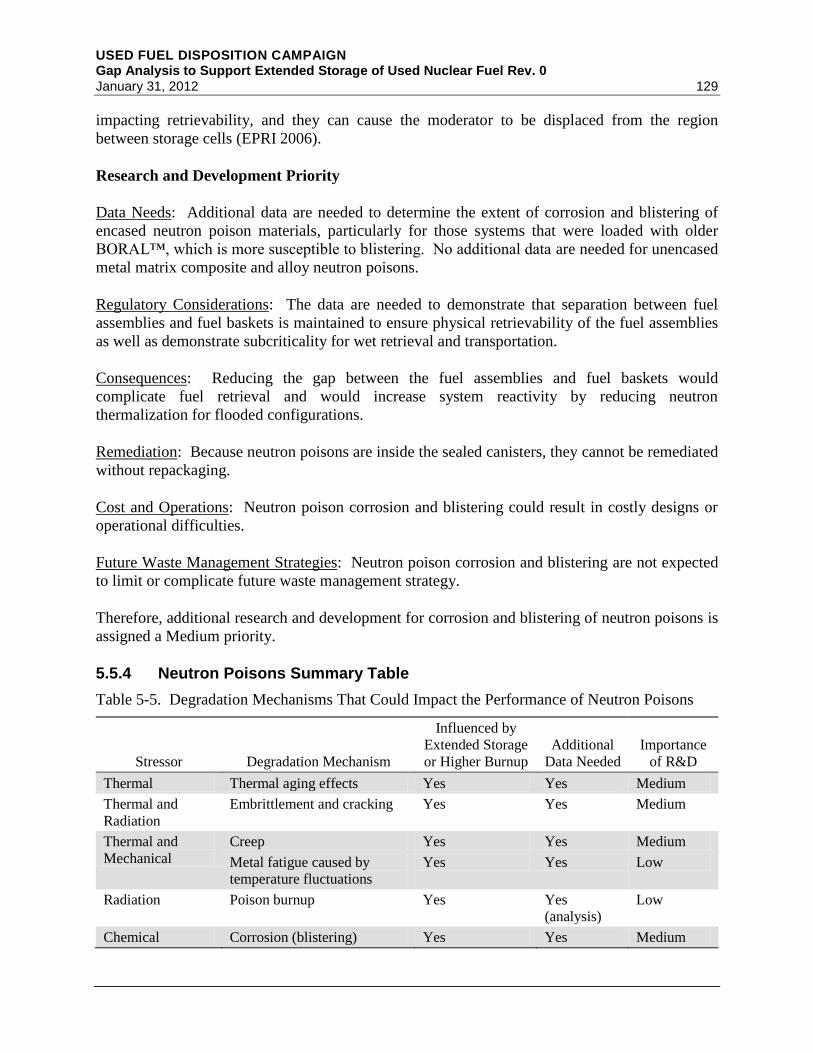
USED FUEL DISPOSITION CAMPAIGN Gap Analysis to Support Extended Storage of Used Nuclear Fuel Rev. 0 January 31, 2012 129
impacting retrievability, and they can cause the moderator to be displaced from the region
between storage cells (EPRI 2006).
Research and Development Priority
Data Needs: Additional data are needed to determine the extent of corrosion and blistering of
encased neutron poison materials, particularly for those systems that were loaded with older
BORAL™, which is more susceptible to blistering. No additional data are needed for unencased
metal matrix composite and alloy neutron poisons.
Regulatory Considerations: The data are needed to demonstrate that separation between fuel
assemblies and fuel baskets is maintained to ensure physical retrievability of the fuel assemblies
as well as demonstrate subcriticality for wet retrieval and transportation.
Consequences: Reducing the gap between the fuel assemblies and fuel baskets would
complicate fuel retrieval and would increase system reactivity by reducing neutron
thermalization for flooded configurations.
Remediation: Because neutron poisons are inside the sealed canisters, they cannot be remediated
without repackaging.
Cost and Operations: Neutron poison corrosion and blistering could result in costly designs or
operational difficulties.
Future Waste Management Strategies: Neutron poison corrosion and blistering are not expected
to limit or complicate future waste management strategy.
Therefore, additional research and development for corrosion and blistering of neutron poisons is
assigned a Medium priority.
5.5.4 Neutron Poisons Summary Table
Table 5-5. Degradation Mechanisms That Could Impact the Performance of Neutron Poisons
Stressor Degradation Mechanism
Influenced by
Extended Storage
or Higher Burnup
Additional
Data Needed
Importance
of R&D
Thermal Thermal aging effects Yes Yes Medium
Thermal and
Radiation
Embrittlement and cracking Yes Yes Medium
Thermal and
Mechanical
Creep Yes Yes Medium
Metal fatigue caused by
temperature fluctuations
Yes Yes Low
Radiation Poison burnup Yes Yes
(analysis)
Low
Chemical Corrosion (blistering) Yes Yes Medium

USED FUEL DISPOSITION CAMPAIGN Gap Analysis to Support Extended Storage of Used Nuclear Fuel Rev. 0
130 January 31, 2012
5.5.5 Approach to Closing Neutron Poisons Gaps
The required testing and modeling to close the data gaps for neutron poisons aims at evaluating
continued efficacy of neutron poisons during extended dry storage in order to meet future
retrieval and transportation requirements. The required effort consists of two primary tasks. The
first task is to perform source term analyses to determine accurate ranges of radiation exposure
profiles for neutron poisons as a function of storage configuration, burnup and duration.
Additionally, the thermal modeling described in Section 4.1 is needed to determine neutron
poisons thermal profiles as a function of extended storage. The second task is to determine
neutron poison materials performance, including poison isotope areal density and material
structural properties, as function of a range of individual and compounded thermal, mechanical,
chemical, and radiation stressors, including thermal aging effects, thermal and radiation
embrittlement and cracking, creep, and corrosion (blistering).
The tests require a sufficient number of samples that cover the materials of construction and the
variability within these materials based on changes or improvements of metallurgical processes
as described in Section 5.5.1.
5.6 Neutron Shields
5.6.1 Introduction
The function of neutron shields is to provide radiation protection by slowing down and absorbing
neutrons. Neutron shielding for most storage systems is provided by the concrete overpack
(Section 5.8). For some dual-purpose (storage and transportation) systems, which make up
approximately 15% of the currently loaded casks, neutron shields are made from a variety of
polymer-based materials composed of an effective neutron moderator, such as hydrogen and
carbon, and a neutron poison, such as boron. There are variations within each material based on
specific polymer–resin type and fabrication technique, which could have significant impact on
material performance.
Although neutron shields provide a radiation protection function during normal operations, they
are expected to degrade under some design basis accidents, including fire events. Metal casks,
which utilize neutron shields, are generally designed to meet both storage and transportation
requirements. 10 CFR 71.55 requires that for transportable casks, the external radiation dose rate
shall not exceed 1 rem/hr (10 mSv/hr) at 1 m during hypothetical accident conditions, which
include an 800°C fire for 30 minutes. Neutron shields are not credited to meet this dose
requirement.
For example, the dose for the HI-STAR 100 storage and transportation cask (Holtec 2002) with
full credit for neutron shields at 1 m is 51 mrem/hr. With complete loss of neutron shields, the
dose rate increases to 491 mrem/hr, using the limiting design basis source term. The neutron
source term accounts for over 75% of this dose rate (388 mrem/hr). The neutron source term is
dominated by spontaneous fissions of relatively short-lived actinides. Over 90% of the neutron
source term at 5 years cooling is due to 244
Cm, which has a half-life of 18 years. Therefore, with
extended storage, the complete loss of neutron shields is of low consequence. In addition,

USED FUEL DISPOSITION CAMPAIGN Gap Analysis to Support Extended Storage of Used Nuclear Fuel Rev. 0 January 31, 2012 131
continued functioning of the neutron shields may be monitored relatively easily from outside the
dry storage cask systems, with remedial action taken if gaps in the protection occur.
5.6.2 Analysis of Safety Functions
Degradation of neutron shields affects the five storage safety functional areas as follows:
Retrievability: No impact.
Thermal Performance: The conservative analytical treatment of the thermal properties of
neutron shields obviates any impacts that their degradation could have on the thermal
performance function of storage systems.
Radiological Protection: Neutron shields provide a radiation protection function by slowing
down neutrons with their high hydrogen and/or carbon content and then absorbing the neutrons
with a strong neutron poison such as boron.
Confinement: No impact.
Subcriticality: No impact.
Based on the four potential stressors (thermal, radiation, chemical, and mechanical), the
identified degradation mechanisms that can result in neutron poison isotope or moderator density
reduction are thermal embrittlement, cracking, shrinkage and decomposition; poison burnup;
radiation embrittlement and cracking; and wet corrosion. Table 5-6 in Section 5.6.4 provides the
results of the degradation mechanisms analysis.
Importance of System to Licensing: Because neutron shields are used to manage occupational
exposures and is needed for only the first few decades of storage, its importance to licensing of
extended storage is Low.
5.6.3 Discussion of Neutron Shields Issues
Degradation mechanisms for neutron shields during extended dry storage and additional research
and development needs are discussed and prioritized in this section. NWTRB (2010) discusses
the performance requirements of neutron shields but does not discuss their degradation
mechanisms separately from neutron poisons, which are discussed in Section 5.5.
5.6.3.1 Thermal Embrittlement, Cracking, Shrinkage and Decomposition
Literature Search and Degradation Mechanism Analysis
The nature of the degradation of neutron shielding materials at higher temperatures depends on
the specific material. For example, polyethylene rods may experience some shrinkage, which
could lead to significant local loss of neutron shielding. Other neutron-shielding materials can

USED FUEL DISPOSITION CAMPAIGN Gap Analysis to Support Extended Storage of Used Nuclear Fuel Rev. 0
132 January 31, 2012
experience loss of hydrogen at higher temperatures. The lower temperatures associated with
extended storage will likely lead to a lower rate of degradation (EPRI 2002b, p. 3-10).
Research and Development Priority
Data Needs: Additional data through accelerated thermal aging of the various types of neutron
shields would aid in evaluating the long-term behavior of such materials.
Regulatory Considerations: Although not required, the presence of neutron shields facilitates
meeting the 10 CFR 20 occupational dose and ALARA requirements. With reduced neutron
source term during extended storage, thermal embrittlement, cracking, shrinkage, and
decomposition of neutron shields are not expected to impact any regulatory requirements.
Likelihood of Occurrence: Thermal embrittlement, cracking, shrinkage, and decomposition of
neutron shields are potentially likely during extended storage.
Consequences: The consequences of thermal embrittlement, cracking, shrinkage, and
decomposition of neutron shields are minimal and are expected to result in manageable increases
in occupational dose.
Remediation: For most metal cask systems, neutron shields are on the outside and can be easily
remediated if gaps in the protection occur.
Cost and Operations: Thermal embrittlement, cracking, shrinkage, and decomposition of neutron
shields are not expected to result in costly designs or operational difficulties.
Future Waste Management Strategies: Thermal embrittlement, cracking, shrinkage, and
decomposition of neutron shields are not expected to limit or complicate future waste
management strategy.
Therefore, additional research and development for evaluating thermal embrittlement, cracking,
shrinkage, and decomposition of neutron shields is assigned a Low priority.
5.6.3.2 Poison Burnup
Literature Search and Degradation Mechanism Analysis
The amount of neutron poison used up by the neutron flux during the first 20 years of storage is
negligible. Thus, extended storage under neutron fluxes significantly lower than during the first
20 years will also likely have an insignificant effect on the available neutron poison
(EPRI 2002b, p. 3-13)
Research and Development Priority
Data Needs: An analysis of neutron source term as a function of extended storage is needed to
demonstrate that poison burnup is insignificant.

USED FUEL DISPOSITION CAMPAIGN Gap Analysis to Support Extended Storage of Used Nuclear Fuel Rev. 0 January 31, 2012 133
Regulatory Considerations: Although not required, the presence of neutron shields facilitates
meeting the 10 CFR 20 occupational dose and ALARA requirements. With reduced neutron
source term during extended storage, poison burnup is not expected to impact any regulatory
requirements.
Likelihood of Occurrence: Poison burnup is unlikely during extended storage.
Consequences: The consequences of poison burnup are insignificant and are not expected to
result in any increase in occupational dose.
Remediation: For most metal cask systems, neutron shields are on the outside and can be easily
remediated if gaps in the protection occur.
Cost and Operations: Poison burnup is not expected to result in costly designs or operational
difficulties.
Future Waste Management Strategies: Poison burnup is not expected to limit or complicate
future waste management strategy.
Therefore, additional research and development for evaluating poison burnup of neutron shields
is assigned a Low priority.
5.6.3.3 Radiation Embrittlement
Literature Search and Degradation Mechanism Analysis
The threshold for radiation embrittlement is about 106 rad for polyethylene and lower for
polytetrafluoroethylene or Teflon (EPRI 1998, p. 5-3). Depending on the fuel, neutron shields
could reach this dose by 100 years. Therefore, embrittlement of polymeric neutron shields
during extended storage is expected.
Research and Development Priority
Data Needs: An analysis of neutron source term as a function of extended storage is necessary to
determine the level of radiation exposure of neutron shields as a function of extended storage.
Regulatory Considerations: Although not required, the presence of neutron shields facilitates
meeting the 10 CFR 20 occupational dose and ALARA requirements. With reduced neutron
source term during extended storage, radiation embrittlement of neutron shields is not expected
to impact any regulatory requirements.
Likelihood of Occurrence: Radiation embrittlement of neutron shields is likely during extended
storage.
Consequences: The consequences of radiation embrittlement of neutron shields are insignificant
and are not expected to result in any increase in occupational dose.

USED FUEL DISPOSITION CAMPAIGN Gap Analysis to Support Extended Storage of Used Nuclear Fuel Rev. 0
134 January 31, 2012
Remediation: For most metal cask systems, neutron shields are on the outside and can be easily
remediated if gaps in the protection occur.
Cost and Operations: Radiation embrittlement of neutron shields is not expected to result in
costly designs or operational difficulties.
Future Waste Management Strategies: Radiation embrittlement of neutron shields is not
expected to limit or complicate future waste management strategy.
Therefore, additional research and development for evaluating radiation embrittlement of
neutron shields is assigned a Low priority.
5.6.3.4 Wet Corrosion
Research and Development Priority
Corrosion rate of neutron shields during long-term storage is expected to be slower because the
small amount of oxygen inside the region into which the polyethylene was inserted at the time of
cask construction would be used up during the first few years of storage by the surrounding
metal or the polyethylene itself (EPRI 2002b, p. 3-12). However, additional oxygen could
continue to be supplied through potential leaks in the neutron shield casing.
Research and Development Priority
Data Needs: An analysis of rate of corrosion of neutron shields as a function of oxygen presence
and temperature is required.
Regulatory Considerations: Although not required, the presence of neutron shields facilitates
meeting the 10 CFR 20 occupational dose and ALARA requirements. With reduced neutron
source term during extended storage, corrosion of neutron shields is not expected to impact any
regulatory requirements.
Likelihood of Occurrence: Corrosion of neutron shields is potentially likely during extended
storage.
Consequences: The consequences of corrosion of neutron shields are insignificant and are not
expected to result in any increase in occupational dose.
Remediation: For most metal cask systems, neutron shields are on the outside and can be easily
remediated if gaps in the protection occur.
Cost and Operations: Corrosion of neutron shields is not expected to result in costly designs or
operational difficulties.
Future Waste Management Strategies: Corrosion of neutron shields is not expected to limit or
complicate future waste management strategy.
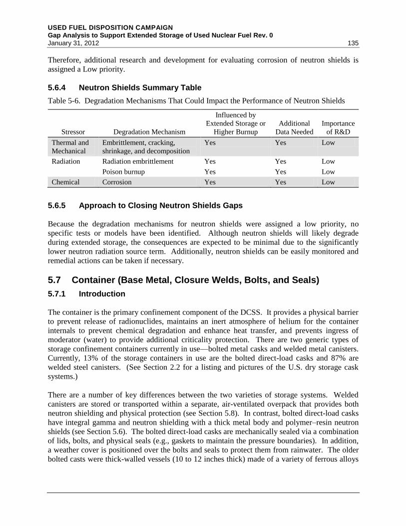
USED FUEL DISPOSITION CAMPAIGN Gap Analysis to Support Extended Storage of Used Nuclear Fuel Rev. 0 January 31, 2012 135
Therefore, additional research and development for evaluating corrosion of neutron shields is
assigned a Low priority.
5.6.4 Neutron Shields Summary Table
Table 5-6. Degradation Mechanisms That Could Impact the Performance of Neutron Shields
Stressor Degradation Mechanism
Influenced by
Extended Storage or
Higher Burnup
Additional
Data Needed
Importance
of R&D
Thermal and
Mechanical
Embrittlement, cracking,
shrinkage, and decomposition
Yes Yes Low
Radiation Radiation embrittlement Yes Yes Low
Poison burnup Yes Yes Low
Chemical Corrosion Yes Yes Low
5.6.5 Approach to Closing Neutron Shields Gaps
Because the degradation mechanisms for neutron shields were assigned a low priority, no
specific tests or models have been identified. Although neutron shields will likely degrade
during extended storage, the consequences are expected to be minimal due to the significantly
lower neutron radiation source term. Additionally, neutron shields can be easily monitored and
remedial actions can be taken if necessary.
5.7 Container (Base Metal, Closure Welds, Bolts, and Seals)
5.7.1 Introduction
The container is the primary confinement component of the DCSS. It provides a physical barrier
to prevent release of radionuclides, maintains an inert atmosphere of helium for the container
internals to prevent chemical degradation and enhance heat transfer, and prevents ingress of
moderator (water) to provide additional criticality protection. There are two generic types of
storage confinement containers currently in use—bolted metal casks and welded metal canisters.
Currently, 13% of the storage containers in use are the bolted direct-load casks and 87% are
welded steel canisters. (See Section 2.2 for a listing and pictures of the U.S. dry storage cask
systems.)
There are a number of key differences between the two varieties of storage systems. Welded
canisters are stored or transported within a separate, air-ventilated overpack that provides both
neutron shielding and physical protection (see Section 5.8). In contrast, bolted direct-load casks
have integral gamma and neutron shielding with a thick metal body and polymer–resin neutron
shields (see Section 5.6). The bolted direct-load casks are mechanically sealed via a combination
of lids, bolts, and physical seals (e.g., gaskets to maintain the pressure boundaries). In addition,
a weather cover is positioned over the bolts and seals to protect them from rainwater. The older
bolted casts were thick-walled vessels (10 to 12 inches thick) made of a variety of ferrous alloys
USED FUEL DISPOSITION CAMPAIGN Gap Analysis to Support Extended Storage of Used Nuclear Fuel Rev. 0
136 January 31, 2012
including nodular cast iron, carbon steel, and low-alloy steel, while the more recent welded
canisters have been constructed with stainless steels.
The external environment to which the container is exposed will impact its long-term
performance. In marine environments, the chloride-containing atmospheric aerosols that are
ubiquitous under such conditions, combined with high relative humidity levels, can lead to
corrosion of the container itself, along with the sealing system (i.e., welds, bolts, or metallic
seals). Localized corrosion (i.e., pitting or crevice corrosion) may take place whenever sufficient
moisture and contamination are present. In addition, in locations where dissimilar metals are in
contact, such as where a metallic seal contacts the container body or lid, galvanic corrosion could
potentially take place. In regions where sufficient stress is present, such as within bolts or in the
heat-affected zone around welds, SCC may take place. In all cases, the actual corrosion
mechanisms, if any, that become active will be dictated by the environment and the materials
under consideration. The potential impact of corrosion on a storage container will be controlled
by the operative corrosion mechanisms over the period of performance of the storage system as
well as the period over which they occur.
5.7.2 Analysis of Safety Functions
The container performs, at least in part, all five key safety functions: thermal performance,
radiological protection, confinement, subcriticality, and retrievability.
Retrievability: The container ensures the retrievability of the fuel by maintaining its physical and
chemical integrity. It provides a substantial physical barrier to alleviate potential structural
damage and prevents chemical damage by maintaining an inert atmosphere around the fuel
assemblies.
Thermal Performance: Mitigation of the heat generated by the used nuclear fuel within the
waste container is enhanced by the use of a helium backfill.
Radiological Protection: The container provides some radiation shielding, especially in the
direct-load bolted casks that are made with integral gamma and neutron shielding (see
Section 5.6). For the welded canisters, the steel provides some shielding, although its
contribution is minor when compared to that of the transfer or storage overpacks (Section 5.8).
Confinement: The container is the primary physical barrier of the DCSS, providing a pressure
boundary that holds an inert atmosphere and isolates radionuclides from the external
environment.
Subcriticality: During storage, subcriticality is maintained by the exclusion of moderator (water)
from the interior of the container.
The degradation mechanisms associated with the container are summarized in Section 5.7.4,
Table 5-7.
USED FUEL DISPOSITION CAMPAIGN Gap Analysis to Support Extended Storage of Used Nuclear Fuel Rev. 0 January 31, 2012 137
Importance of System to Licensing: Because the container is the primary confinement barrier
and its breach may result in release of radionuclides to the environment, its importance to
licensing is High.
5.7.3 Discussion of Selected Container Issues
The welded canisters differ from the bolted, direct-load casks in both their materials of
construction and the method of closure, and are thus discussed separately.
Welded canisters are robust, with little degradation due to thermal, mechanical, or radiation
stressors. However, the canisters are exposed to the atmosphere and may undergo atmospheric
or aqueous corrosion in some situations. For this reason, newer welded canisters are made of a
corrosion-resistant stainless steel. The areas of welded canisters most susceptible to
environmentally induced degradation are the closure welds, which are neither annealed nor stress
mitigated and thus have significant residual stress that may lead to stress corrosion cracking
when exposed to sufficiently aggressive environments.
The degradation of bolts and seals in confinement systems is discussed in Sections A3.3.3.2 and
A3.3.3.3 of ASTM C1562-10. For bolted casks, the features most susceptible to degradation are
the closure bolts and seals. Although the seals are normally dry and protected by a weather
cover, there may be residual borated water trapped within the seals due to incomplete drying
after being loaded in the pool or water from the external environment deposited via capillary
condensation. While more modern bolted casks have a double metallic O-ring seal, some older
designs had a metallic inner and elastomeric O-ring secondary seal. In such older designs,
primary confinement is achieved with a metal seal, and secondary confinement either with an
elastomeric seal or a second metal seal. The elastomeric seal is never the primary confinement
seal.
The conditions to which the environmental seals are exposed can have a detrimental impact on
their performance. In the case of the metal seals, although radiation generally does not impact
their performance, the thermal excursions to which they are exposed can compromise the seal by
causing the material to creep, thermally fatigue, or otherwise change in mechanical properties.
In addition to impacting the performance of metal seals, the thermal and radiation exposure can
degrade the physical properties of the bolts used to secure the lid. As with the seals, creep may
lead to eventual unloading of the bolts and the loss of an effective seal. In addition,
thermomechanical fatigue due to temperature cycling may lead to crack initiation at threads or
other stress raisers, and the temperature excursions themselves may result in changes in the
mechanical properties of the fasteners.
In Appendix D of NUREG-1927 (NRC 2011c), the NRC outlines the aging effects and possible
degradation mechanisms for the structural steel members (such as the storage container) that they
consider important for an ISFSI or DCSS.

USED FUEL DISPOSITION CAMPAIGN Gap Analysis to Support Extended Storage of Used Nuclear Fuel Rev. 0
138 January 31, 2012
Aging Effects of SSCs Possible Aging Mechanism
Loss of material Corrosion (general or localized)
Loss of strength and modulus Elevated temperature
Loss of fracture toughness Irradiation
Crack initiation and growth Stress corrosion cracking
Furthermore, in Appendix E of NUREG-1927, specific guidance is given with respect to an
aging management program (AMP) for canisters. In that document, it is noted that material
selection is done such that corrosion-resistant materials are used. To ensure that the canister is
functioning properly at license renewal, the applicant will have to demonstrate that the canisters
have not undergone any unanticipated degradation. An acceptable approach to verify this is via
remote visual inspection of one or more canisters, with the selected canisters being identified on
the basis of the longest exposure time, highest thermal load, and/or other key parameters that
might contribute to degradation of the canister.
5.7.3.1 Atmospheric Corrosion of Welded Containers
Literature Search and Degradation Mechanism Analysis
The welded canisters are typically stored in ventilated concrete overpacks, which protect them
from direct contact with rainwater but not from exposure to the atmosphere; thus, atmospheric
corrosion is a potential degradation mechanism. Corrosion-resistant materials such as stainless
steels are largely immune to the effects of atmospheric corrosion under all but the most severe of
exposure conditions. Because recently produced welded containers have thick (0.5-inch to
0.625-inch) stainless steel walls (e.g., the NUHOMS DSC, NAC MPC, and HI-STORM MPC), it
is unlikely that either atmospherically induced general or localized corrosion would compromise
the structural integrity of the container. Stress corrosion cracking of the welds in humid
environments is the most likely atmospheric degradation mechanism for welded stainless steel
containers, although the risk of canister breach is relatively low unless salt deposition is high.
Less corrosion-resistant materials, such as the carbon steels used in early welded container
designs, are more likely to undergo atmospheric corrosion to a measureable degree.
Atmospheric corrosion is a concern in environments where a combination of high moisture
content and aggressive ion-containing contamination are present that could lead to enhanced
corrosion, such as in polluted industrial areas and in marine environments. For marine exposure,
the dominant form of aggressive ions comes from salt particles formed from seawater aerosols.
Depending on the relative humidity of the environment and the size of the particulates, these salt
particles can be either actual droplets of seawater, droplets of evaporatively concentrated brine,
or solid salt particulates (Blanchard and Woodcock 1980). Irrespective of their physical form, all
result in the delivery of chloride-rich contaminants onto the metal surface.
The mechanisms observed for atmospheric corrosion are similar to those observed in bulk
aqueous solutions—namely general and localized corrosion of various forms, including pitting,
crevice corrosion, and stress corrosion cracking. Atmospheric corrosion processes are
profoundly impacted by the morphology and physical configuration of the corroding surfaces as

USED FUEL DISPOSITION CAMPAIGN Gap Analysis to Support Extended Storage of Used Nuclear Fuel Rev. 0 January 31, 2012 139
well as their position relative to any potential sources of moisture or solid contamination.
Morphology is determined by surface roughness (scratches) and presence of contaminants (such
as chloride-bearing salt particles). As such, it is imperative that there is a means to assess the
environment to which the containers at a specific site are exposed. The analysis should capture
seasonal variations in temperature, moisture content, and contamination deposition (particularly
for marine environments). The result of this effort will establish both which materials of
construction are appropriate for a particular location and the conditions under which the
acceptable performance materials of construction must be verified.
Three factors are necessary for SCC: stress (either residual or applied), a susceptible material,
and a sufficiently aggressive environment. In marine locations, some austenitic stainless steels
have been demonstrated to be susceptible to such degradation. SCC of sensitized stainless steels
in marine exposure was been observed for 201, 301, 302, 304, 309, and 316 stainless steel when
exposed at the LaQue Kure beach site (Kain 1990). In that same study, several other
observations were made. First, annealed and moderately cold-worked stainless steels were
largely immune to SCC unless a crevice was present. In addition, the susceptibility of the steels
to SCC and hence the extent to which cracking occurred, correlated with the carbon content of
the steel. In other words, “L” grade stainless steels were far less susceptible than their normal
carbon level counterparts. In a more recent Japanese study (Tani et al. 2008; Tani et al. 2009;
Shirai et al. 2011a), the SCC susceptibility of stainless steel canisters for dry storage of used
nuclear fuel in marine environments has been explored. In that work, the performance of more
commonly applied stainless steels (304L and 316L) was evaluated, alongside several 6% Mo
stainless steels designed for increased resistance to localized attack (UNS S31260 [duplex] and
UNS S31254 [austenitic]). As with the earlier LaQue study, Tani and Shirai et al. observed that
the standard stainless steels (i.e., 304L and 316L in this case) were susceptible, but the more
highly alloyed materials (i.e., a 6% Mo duplex and a 6% Mo austenitic stainless steel) were
effectively immune. Although the more modern 6% Mo alloys were immune, they carry with
them a substantial increase in cost. As a result, Japanese current research is aimed at evaluating
stress mitigation techniques to improve the performance of less costly materials such as
304L stainless steel, as well as developing means to reduce the deposition of chloride-bearing
salt particles onto the canister surface. Other similar studies include the work of Caseres and
Mintz (2010) who also evaluated atmospheric stress corrosion cracking in austenitic stainless
steels to investigate this degradation mechanism in DCSCs in marine environments. Their work,
which evaluated the performance of a number of stainless steels at a range of temperatures,
found that SCC did not occur at temperatures in excess of 85°C. This work suggests that SCC is
not likely to be a problem during the early years of storage when the containers are above 85°C
but could become a viable degradation mechanism for extended storage times if the circulating
air contains significant chloride-containing particulate.
For any ITS metal exposed to the external environment, it must be demonstrated that
atmospheric corrosion will not significantly degrade its safety functions within the license
period. Such demonstration includes the basic materials of construction, as well as any specific
geometries associated with the storage system or microstructural changes brought about by
assembly processes such as welding. This requires the characterization of both the environment
to which the system will be exposed and the atmospheric corrosion performance of the container
materials when exposed to relevant environments. In the case of marine environments, key

USED FUEL DISPOSITION CAMPAIGN Gap Analysis to Support Extended Storage of Used Nuclear Fuel Rev. 0
140 January 31, 2012
variables that must be understood include the deposition rate of salt particulates on a relevant
material surface and the typical chemistry of those aerosols. Most initial SARS for welded
containers simply state that for non-marine environments, the interior of the overpack will be
relatively mild (warm and dry) and the stainless steel alloys used have a proven history of
material integrity under these conditions (Holtec 2000; Transnuclear 2001; NAC 2004).
Any plausible degradation processes that may directly impact the structural integrity of the
container must be well understood, such that appropriate materials and processing techniques can
be selected. While appropriate material selection can prevent atmospheric corrosion, older
designs (VSC-24 and W150) contain less corrosion-resistant materials, such as carbon and low-
alloy steels, which can readily undergo atmospheric corrosion. These materials are normally
coated to prevent corrosion in the pool during loading. If the coating is maintained after loading,
it can also prevent atmospheric corrosion.
The NWTRB (2010, p. 105) identified atmospheric corrosion as a potential degradation
mechanism for the container. They stressed the importance of all chemical species in the
atmosphere, including dust, as well as the effects of gamma radiation on these contaminants,
such as production of nitric acid in irradiated moist air or halogen from irradiated halide salts.
Research and Development Priority
Data Needs: There are sufficient data available to evaluate the potential for atmospheric
corrosion to occur during the licensing period, given that the materials and environment are
known. However, predictions of the environment for extended storage are required.
Regulatory Considerations: The ability of a container to maintain its integrity and provide waste
confinement is a critical aspect of the DCSS. Environmentally induced degradation of the
welded canisters, especially the more rapid modes of corrosion such as SCC, can lead to loss of
confinement during the license period.
Likelihood of Occurrence: The likelihood of the atmospheric corrosion of the older-design casks
can be significant if the coatings on the older casks are not adequately maintained. The
likelihood of marine atmosphere SCC for extended storage is also significant.
Consequences: The impact of atmospheric general corrosion likely will be minimal because the
newer stainless containers are effectively immune and older corrosion-allowance materials are
sufficiently thick walled. Localized corrosion of metallic seals in bolted containers or SCC of
the weldments in newer containers could result in a potential breach of the container and is an
unacceptable consequence.
Remediation: AMPs are hindered by the overall construction of the DCSS, where many of the
areas that must be inspected (e.g., welds on newer containers) are obscured by the overpack.
Remediation of a cracked weldment could require either repair or replacement of the canister,
depending on the assessment of the extent of damage.

USED FUEL DISPOSITION CAMPAIGN Gap Analysis to Support Extended Storage of Used Nuclear Fuel Rev. 0 January 31, 2012 141
Cost and Operations: Replacement of the canister would involve relocation of the used nuclear
fuel to a new canister, which would have high cost and the potential for significant worker dose.
Future Waste Management Strategies: No impact.
Therefore, additional research and development for environmentally induced degradation (e.g.,
atmospheric corrosion or SCC) of the welded canisters is assigned a High priority.
5.7.3.2 Aqueous Corrosion of Welded Container
Literature Search and Degradation Mechanism Analysis
With time, waste container temperatures will decrease, allowing for the formation of
condensation on the inside of the overpack and on the container surface. Water may also be
present if there is inadequate drying or the overpack fails to protect the container from rainwater.
Unlike the atmospheric corrosion scenarios discussed in Section 5.7.3.1, the environment present
when condensation takes place is effectively a bulk aqueous environment. As with atmospheric
corrosion conditions, the chemical composition of the aqueous phase will be a strong function of
solid and liquid contamination delivered from the environment to the metal surface. If the
solution chemistry is sufficiently aggressive, aqueous corrosion of the storage containers may
occur. While the active corrosion mechanisms will be determined by the combination of
material and environment (e.g., chloride concentration, presence of occluded geometries,
concrete), they can include general corrosion, localized corrosion (i.e., pitting and crevice
corrosion), SCC, and galvanic corrosion.
The ability of a welded container to maintain its integrity and provide waste confinement is a
critical aspect of the DCSS. Any plausible degradation processes that may directly impact the
structural integrity of the container must be well understood such that appropriate materials and
processing techniques can be selected. While appropriate material selection can minimize the
impact of any potential aqueous corrosion, existing designs contain many materials, such as
carbon and low alloy steels, which are highly susceptible to general and/or localized corrosion
under inundated conditions.
The NWTRB identified pitting, crevice, and galvanic corrosion, as well as SCC as potential
degradation mechanisms for the container: “There is an insignificant risk of canister wall failure
due to pitting or crevice corrosion unless the duration of storage is very long. A metal canister’s
corrosion lifetime for pitting and crevice corrosion can be estimated as the time needed for the
canister to decline to a temperature where corrosive aqueous environments are possible (i.e.,
below about 100°C), plus the time for electrochemical corrosion to propagate through canister
wall thickness” (NWTRB 2010, p. 106). The NWTRB cites Kosaki (2008), who predicts the
failure of a 13-mm canister between 430 and 650 years after the temperature on the canister has
dropped sufficiently to allow condensation. Galvanic corrosion can occur whenever dissimilar
metals are in contact with each other in the presences of an electrolyte.

USED FUEL DISPOSITION CAMPAIGN Gap Analysis to Support Extended Storage of Used Nuclear Fuel Rev. 0
142 January 31, 2012
Research and Development Priority
Data Needs: While there are sufficient data to evaluate aqueous corrosion and container
performance, the likelihood of aqueous corrosion is currently unknown. Aqueous corrosion will
depend on the temperature at the container surface and the degradation state of the overpack.
Data needs include a thermal analysis of the container surface for a variety of DCSSs.
Regulatory Considerations: The ability of a container to maintain its integrity and provide waste
confinement is a critical aspect of the DCSS. Aqueous corrosion can lead to loss of confinement
during the license period, particularly if localized corrosion or SCC become operative
mechanisms.
Likelihood of Occurrence: Unknown.
Consequences: The consequences of aqueous corrosion range from minimal for the generalized
corrosion of the corrosion allowance materials used in the older designs to unacceptable for
breach of the newer stainless steel containers by localized corrosion or SCC.
Remediation: Aging management programs are hindered by the overall construction of the
DCSS, where many of the areas that must be inspected (e.g., welds) are obscured by the
overpack. Remediation involves ensuring the weather protection is functioning correctly and
condensation is not occurring, and can be accomplished with an aging management program.
Cost and Operations: If aqueous corrosion is prevented through an aging management program,
then the cost is small. However, if corrosion is significant enough to require canister
replacement, relocation of the used nuclear fuel to a new canister will be required, which would
have high cost and the potential for significant worker dose.
Future Waste Management Strategies: No impact.
Therefore, additional research and development for aqueous corrosion of the welded canisters is
assigned a High priority.
5.7.3.3 Embrittlement of Elastomer Seals in Bolted Casks
Literature Search and Degradation Mechanism Analysis
Elastomer seals are used as secondary seals of the main confinement boundary and as seals for
protective weather covers. Elastomers are generally very sensitive to radiation exposure and
substantial thermal excursions. Some studies conclude that thermal damage is far more
significant than radiation damage (ASTM C1562-10, A3.3.3.3). In the case of radiation,
exposure drives cross-linking of the polymer, leading to an increased strength and reduced
ductility. Changes in mechanical properties occur after about 106 rad (ASTM C1562-10). The
loss of ductility can have a detrimental impact on the ability to maintain a reliable seal. The
German government supported research institute (BAM) has started investigations of
fluorocarbon rubber and have measured the rubber–glass transition temperature of unirradiated
USED FUEL DISPOSITION CAMPAIGN Gap Analysis to Support Extended Storage of Used Nuclear Fuel Rev. 0 January 31, 2012 143
samples at −29°C (Völzke and Wolff 2011). In addition to changing physical properties,
radiation can cause chemical degradation of the elastomer, resulting in the emission of
decomposition products, which may adversely impact other components of the storage system.
Elevated temperature exposure can also result in a similar chemical breakdown of the elastomer,
accompanied by the production of potentially corrosive decomposition products.
The NWTRB (2010, p. 109) identified component-specific degradation mechanisms including
the effects of radiation and heat on elastomer seals.
Research and Development Priority
Data Needs: There are sufficient data to evaluate embrittlement of secondary elastomer seals.
Regulatory Considerations: Because elastomer seals are used only as back-up to metal seals,
their failure has no regulatory consequence.
Likelihood of Occurrence: High.
Consequences: The use of elastomer in secondary seals is limited to older cask designs with
redundant metal and elastomer seals. Thus, the failure of the elastomer seals does not
compromise confinement, and the consequence of degradation is low. The newer TN designs
use elastomer only in the weather cover seals, which can be replaced as necessary without
opening the cask and exposing radionuclides to the environment.
Remediation: Remediation includes replacing the elastomer seals.
Cost and Operations: For the newer designs, the cost of remediation or age management is lower
than that of the older designs that may need to be returned to the pool and opened.
Future Waste Management Strategies: No impact.
Therefore, additional research and development for embrittlement of secondary elastomer seals
is assigned a Low priority.
5.7.3.4 Thermal Degradation of Fasteners and Metallic Seals in Bolted Casks
Literature Search and Degradation Mechanism Analysis
For the seal to remain intact, the stress imposed by the fasteners used to press the cover onto the
metallic and elastomeric seals must be maintained. Degradation of the elastomeric seals is
discussed in Section 5.7.3.3. Thermal excursions, if sufficiently large, can support creep of both
the metallic seal and the bolts. This creep will result in stress relaxation of the sealing system
and could compromise the integrity of the seal. In addition to creep, fluctuations in temperature
can result in thermomechanical fatigue of the fasteners, potentially leading to crack initiation and
eventual fastener failure. Normal relaxation due to cooling down and thermal relaxation may
cause some detorquing of the bolts.

USED FUEL DISPOSITION CAMPAIGN Gap Analysis to Support Extended Storage of Used Nuclear Fuel Rev. 0
144 January 31, 2012
Analyses of the temperature profiles (axial and radial) of low and high burnup fuels over the
entire period of dry storage (from the start of drying operations to transfer to the ISFSI to
extended dry storage) are needed to determine the exposure conditions under which the
mechanical seal must remain intact. Once temperature histories are calculated, an analysis of
seals and bolts metal fatigue caused by temperature fluctuations can be performed.
In the meantime, BAM (Germany), CRIEPI (Japan), and the French Atomic Energy Commission
have been studying metal seals for thermal degradation, and corrosion due to inadequate drying
(Völzke and Wolff 2011). The French have found no significant changes in seals in a testing
program started in 1973. The Germans have measured the creep of Helicoflex® seals with
aluminum or silver jackets at 150°C but as yet have found no loss of seal tightness, due to the
improved contact between the weak outer jacket material and the sealing flange surface. The
Japanese studied Helicoflex® metal seals kept at 160°C from 1990 to 2010. Shirai et al. (2011b)
measured the relationship between the leak rate and the Larson–Miller parameter. They
concluded that the as long as aluminum-covered gaskets had initial temperatures of below
134°C, or silver-covered gaskets had initial temperatures below 125°C, that sealing performance
would be ensured for 60 years.
The NWTRB (2010, p. 108) identified some component specific degradation mechanisms
including those of bolts and metallic seals: “Bolts are subject to high stress. Under both thermal
accident events and mechanical impact events, relatively brittle welds can fracture. Under
accident thermal events, creep rupture failures also are possible. Metallic seals and gaskets
under high loads can degrade through stress relaxation of the metal, plastic deformation, and
creep.”
Research and Development Priority
Data Needs: Until there are validated calculations of representative temperature histories of
extended storage, there are insufficient data to evaluate the thermal degradation of seals and
bolts, and the likelihood of this degradation mechanism is unknown.
Regulatory Considerations: Thermal degradation of seals and bolts can lead to loss of
confinement.
Likelihood of Occurrence: Unknown.
Consequences: The consequence of seal or bolt failure is loss of regulatory-required
confinement. Because the pressure of the space between the redundant seals is monitored, loss
of confinement may be easily detected.
Remediation: Remediation can range from retightening the bolts to returning the cask to the
pool for replacement of the seals.
Cost and Operations: Cost ranges from minimal (bolt tightening) to high (seal replacement).

USED FUEL DISPOSITION CAMPAIGN Gap Analysis to Support Extended Storage of Used Nuclear Fuel Rev. 0 January 31, 2012 145
Future Waste Management Strategies: No impact.
While issues with fastener or metal seal creep can be avoided by proper materials selection and
system design (provided the environment can be adequately characterized), the ability to
maintain waste isolation/confinement is a critical aspect of any container; As such, the
importance of new research and development in this area is categorized as Medium.
5.7.3.5 Atmospheric Corrosion of Bolted Casks
Literature Search and Degradation Mechanism Analysis
Like the welded canisters, the outer surface of the bolted cask is exposed to the external
environment, and atmospheric corrosion is a potential degradation mechanism (see
Section 5.7.3.1). The bolts and seals are normally protected from rainwater and humidity by a
weather cover, but if this cover fails, the bolts and seals would be subject to corrosion. Bolted
casks have occluded geometries around the bolts and seals, which can result in capillary
condensation where liquid water deposits are formed within the occluded environment. The
resulting liquid layer can enable traditional crevice corrosion to take place at relative humidities
where an aqueous surface layer was not anticipated.
While atmospheric corrosion is not typically a concern for many corrosion-resistant materials
such as stainless steels, it is more likely for corrosion-allowance materials (e.g., carbon or
low-alloy steels), particularly in marine environment installations. For this reason, most
corrosion-allowance materials have a protective organic coating applied.
It must be demonstrated that any viable degradation mechanism such as atmospheric corrosion
will not significantly compromise the safety function of the bolted container within the license
period. Such demonstration includes the basic materials of construction, as well as any specific
geometries associated with the storage system or microstructural changes brought about by
assembly processes such as welding. As such, both the environment to which the system will be
exposed and the atmospheric corrosion performance of the container materials when exposed to
relevant environments must be characterized.
The ability of a container to maintain its integrity and provide waste confinement is a critical
aspect of the DCSS. Any plausible degradation processes that may directly impact the structural
integrity of the container must be well understood, such that appropriate materials and processing
techniques can be selected. While appropriate material selection can prevent atmospheric
corrosion, existing designs contain many materials such as carbon and low-alloy steels, which
can readily undergo atmospheric corrosion. As such, the importance of new research in this area
is categorized as High.
The NWTRB (2010, p. 105) identified atmospheric chemistry corrosion environment as a
potential degradation mechanism for the container.

USED FUEL DISPOSITION CAMPAIGN Gap Analysis to Support Extended Storage of Used Nuclear Fuel Rev. 0
146 January 31, 2012
Research and Development Priority
Data Needs: The atmospheric corrosion of bolted casks is well understood, and there are
sufficient data to indicate that the less corrosion-resistant metals used in bolted cask may
undergo atmospheric corrosion.
Regulatory Considerations: If atmospheric corrosion is significant, the container may be
breached, which is an unacceptable regulatory consequence.
Likelihood of Occurrence: The likelihood of significant atmospheric corrosion (i.e., sufficient
attack to compromise the performance of the container) is low.
Consequences: Unless the corrosion involves a critical structure such as bolts, superficial
corrosion will not degrade the safety functions of the casks, which are often quite thick.
Remediation: The remediation may be simply maintaining the weather cover and surface
coating of the casks, but under extreme conditions it could also involve replacement of the
container.
Cost and Operations: Canister replacement would involve relocation of the used nuclear fuel to
a new canister, which would have high cost and the potential for significant worker dose.
Future Waste Management Strategies: No impact.
Until susceptible containers are replaced, the priority of new research and development is High.
5.7.3.6 Aqueous Corrosion of Bolted Casks
Literature Search and Degradation Mechanism Analysis
Unlike the welded canistered casks, the bolted casks are not protected from the rain except over
the bolts and seals. As with atmospheric corrosion conditions, the chemical composition of the
aqueous phase that forms due to condensation or rain will be a strong function of solid and liquid
contamination delivered from the environment to the metal surface. If the solution chemistry is
sufficiently aggressive, aqueous corrosion of the outer surfaces of the storage containers may
occur. While the active corrosion mechanisms will be determined by the combination of
material and environment (e.g., chloride concentration, presence of occluded geometries), they
can include general corrosion, localized corrosion (i.e., pitting and crevice corrosion), SCC, and
galvanic corrosion.
Corrosion is particularly problematic in situations where the structural integrity of the container
could be threatened, such as when the weather cover over the seals and bolts fails. Seals and
bolts are under stress and thus subject to SCC if wetted. There are examples in the field where
corrosion has led to an unanticipated breach of the storage containers, highlighting the
importance of proper consideration of potential failure mechanism prior to utilizing a system for
waste confinement. For example, EPRI (2002b, p. 4-3) reports “Recently, six casks at Surry
USED FUEL DISPOSITION CAMPAIGN Gap Analysis to Support Extended Storage of Used Nuclear Fuel Rev. 0 January 31, 2012 147
were determined to have leaking outside seals by monitoring. A CASTOR-X cask had galvanic
corrosion of the secondary metallic seal due to the presence of chloride probably from residual
cleaning fluid. Five TN-32 casks experienced galvanic corrosion of the secondary metallic seal
due to water leakage through the protective cover. Based on the monitoring and subsequent
examinations of the seals, corrective actions were taken to prevent a recurrence. The design of
the protective cover was improved and aluminum was replaced by silver secondary seals on new
loadings.” Another example was reported by Aida et al. (2010) in which corrosion of metal seals
due to residual water from insufficient drying was observed in 2000. “The Procedure manual
was updated so that residual water could be completely removed.” Corrosion of metal seals was
also found in 2005 “due to immersion to reactor pool water for several days before opening the
primary lid. Procedure manual will be additionally updated in order to reduce the immersion
duration.”
For any ITS metal exposed to conditions where condensation or rainwater leakage is possible, it
must be demonstrated that any potential aqueous corrosion processes (general, localized, or
SCC) will not significantly degrade its safety functions within the license period. Demonstration
includes the basic materials of construction, as well as any specific geometries associated with
the storage system or microstructural changes brought about by assembly processes such as
bolting. Both the environment to which the system will be exposed and the atmospheric
corrosion performance of the container materials in relevant environments require
characterization. In the case of marine environments, key variables that must be understood
include the deposition rate of salt particulates on a relevant material surface and the typical
chemistry of those aerosols.
The ability of a container and its subcomponents (e.g., welds, fasteners) to maintain their
integrity and provide waste confinement is a critical aspect of the DCSS. Any plausible
degradation processes that may directly impact the structural integrity of the container must be
well understood, such that appropriate materials and processing techniques can be selected.
While appropriate material selection can minimize the impact of any potential aqueous
corrosion, existing designs contain many materials such as carbon and low alloy steels, which are
susceptible to significant corrosion under inundated conditions.
The NWTRB (2010, p. 106) identified pitting, crevice, galvanic corrosion, and SCC as potential
degradation mechanisms for the container.
Research and Development Priority
Data Needs: While there are sufficient data to evaluate aqueous corrosion of bolted casks, these
data indicate that the likelihood of occurrence of the aqueous corrosion of has been high (it has
occurred due to failure of a weather cover and due to insufficient drying).
Regulatory Considerations: Failure of bolts or seals can lead to loss of confinement.
Likelihood of Occurrence: As remedial measures are taken, the likelihood of occurrence should
decrease.

USED FUEL DISPOSITION CAMPAIGN Gap Analysis to Support Extended Storage of Used Nuclear Fuel Rev. 0
148 January 31, 2012
Consequences: If failure of the weather protection of the container is undetected, or
condensation occurs, the container may be breached, which is an unacceptable regulatory
consequence.
Remediation: Remediation involves ensuring the weather protection is functioning correctly and
condensation is not occurring under the weather cover. This can be accomplished with an aging
management program. Remediation also includes inspecting any external coatings and repairing
them as necessary. Alternately, the casks may be moved indoors, as is done in some countries.
Cost and Operations: An aging management program is cost-effective and should prevent the
need to return the cask to the pool.
Future Waste Management Strategies: No impact.
However, until it can be demonstrated that aqueous corrosion can be reliably prevented by an
AMP, the priority of new research and development remains High.
5.7.4 Container Summary Table
Table 5-7. Degradation Mechanisms That Could Impact the Performance of the Container –
Welded Canister or Bolted Direct-Load Casks
Stressor Degradation Mechanism
Influenced by
Extended Storage
or Higher Burnup
Additional
Data Needed
Importance
of R&D
Welded Canister
Chemical Atmospheric Corrosion
(Including Marine
Environment)
Yes Yes High
Aqueous Corrosion: general,
localized (pitting, crevice),
SCC, galvanic
Yes Yes High
Bolted Direct-Load Casks
Thermal and
Mechanical
Embrittlement of elastomer
seals
Yes Yes Low
Thermo mechanical fatigue
of seals and bolts
Yes Yes Medium
Radiation Embrittlement of elastomer
seals
Yes Yes Low
Chemical Atmospheric Corrosion
(Including Marine
Environment)
Yes Yes High
Aqueous corrosion: general,
localized (pitting, crevice),
SCC, galvanic
Yes Yes High

USED FUEL DISPOSITION CAMPAIGN Gap Analysis to Support Extended Storage of Used Nuclear Fuel Rev. 0 January 31, 2012 149
5.7.5 Approach to Closing Container Gaps
For the container, degradation processes that directly impact the ability of the system to maintain
its environmental seal have been given a high priority. These include phenomena such as
localized corrosion, galvanic corrosion, and stress corrosion cracking of key components of the
sealing system (e.g., metallic O-ring seals, weldments). Understanding the environments to
which the containers are subjected is critical in order to ensure that the degradation processes of
concern are evaluated under a relevant set of environmental parameters (e.g., temperature,
humidity, surface contamination). To address these concerns, a program that encompasses a
variety of research areas is needed. The proposed approach would begin with the experimental
evaluation of relevant environmental parameters and corrosion degradation processes. The
experimental results would then be used to generate a predictive model that could in turn be
utilized to establish the time-dependent potential for seal failure, given the design of the storage
container and relevant environmental parameters. This model would then provide input to an
AMP with the goal of assessing the time-dependent risk of seal failure associated with a specific
storage system. The experimental program and development of this model will be done in
collaboration with the disposal research being done in the UFDC. Also, the Japanese (CRIEPI)
and Germans (BAM) have been studying the degradation of seals for many years. The DOE will
explore how to best use its resources to collaborate with international researchers through the
ESCP.
5.8 Overpack/Storage Module for Canistered Fuel
5.8.1 Introduction
While the container is the primary confinement component of the DCSS, it is housed within an
overpack or storage module, typically constructed of steel-reinforced concrete. As a result,
although the overpack or storage module does not provide primary confinement of used nuclear
fuel, it does dictate the environment to which the storage container is exposed. Thus,
understanding the aging characteristics of the storage module is a critical factor in determining
the long-term performance of a DCSS.
Some overpacks such as the HI-STORM, or modules such as NUHOMS, have steel parts that are
not embedded within the concrete. These will have the same degradation mechanisms as the
steel containers covered in Section 5.7. This section focuses on reinforced concrete.
5.8.2 Analysis of Safety Functions
The primary functions of overpacks/storage modules (referred to in this document as
“overpacks”) are to 1) protect the canister from direct contact with the environment, under both
normal and abnormal (i.e., accident) conditions; 2) provide radiation shielding, thereby
minimizing the exposure to workers and other surrounding objects/structures; and 3) provide
thermal management for the storage cask by facilitating heat removal, thereby minimizing
temperature excursions. Thus the overpack directly supports three of the five key safety
functions of the DCSS—thermal performance, radiological protection, and retrievability. The
overpack also indirectly supports the confinement function of the canister.

USED FUEL DISPOSITION CAMPAIGN Gap Analysis to Support Extended Storage of Used Nuclear Fuel Rev. 0
150 January 31, 2012
Although the overpack plays a significant safety role, it does not provide the primary
confinement role which the canister does. The overpack is generally on the outside of the DCSS,
and any issues associated with degradation processes can typically be addressed through an AMP
that can include inspection, repair, or replacement with fairly minimal dose exposure or risk of
damaging fuel or the rest of the DCSS. However, the cost increases dramatically from
inspection, to repair, to replacement, so it is important that the AMP provides for detection of
any degradation at an early stage. As a result, the priority of new research on concrete
degradation mechanisms is Low with respect to licensing a DCSS, but the priority of inspection
and an AMP is Medium.
Degradation of the concrete overpack affects the five storage safety functional areas as follows:
Retrievability: Gross degradation of the overpack may hinder retrievability.
Thermal Performance: Because concrete is a thermal insulator, it is important to the thermal
management of the DCSS that any structural features such as air cooling channels remain free of
debris.
Radiological Protection: The concrete overpack provides significant radiation shielding during
storage.
Confinement: The concrete overpack indirectly supports confinement by protecting the
container.
Subcriticality: Other than indirect support by providing protection for the container, the
overpack has no direct subcriticality function.
Table 5-8 in Section 5.8.4 summarizes the degradation mechanisms for concrete overpacks. .
Importance of System to Licensing: Because the overpack protects the confinement barrier, its
importance to licensing is High.
5.8.3 Discussion of Selected Concrete Overpack Issues
An overview of the factors impacting the durability of concrete for nuclear power plant
structures, many of which are of equal relevance to a DCSS, is presented in NUREG/CR-6927
(Naus 2007). The degradation mechanisms for concrete structures of relevance to a DCSS are
also described in Section A5.4 in ASTM C1562-10 and are summarized below. All of these
areas have been heavily investigated by previous researchers, so a thorough literature review
should be completed prior to constructing a detailed research plan for any of them.
It should be stressed that concrete properties are a strong function of the mix design from which
they are formulated. Water fraction, aggregate type and quantity, and other mixture
characteristics combine to determine the ultimate mechanical properties of the concrete, as well
as other factors such as its pore structure and hence permeability. Further, numerous admixtures
USED FUEL DISPOSITION CAMPAIGN Gap Analysis to Support Extended Storage of Used Nuclear Fuel Rev. 0 January 31, 2012 151
also can have a significant impact on the properties of the concrete and its resistance to specific
degradation processes. For these reasons, care must be taken to tailor the concrete mix design to
the specific application in which it is being used (e.g., if it needs high compressive strength,
needs to cure in a reduced timeframe) as well as to when/how the curing process is allowed to
proceed. The American Concrete Institute (ACI) has issued a number of specifications that
attempt to capture and control the key aspects of the concrete mix design for different
applications; these should be followed closely if possible, as deviations may result in undesirable
changes in the properties of the concrete.
5.8.3.1 Exposure to Elevated Temperatures (Dry-Out)
Literature Search and Degradation Mechanism Analysis
Exposure to elevated temperatures (100°C) results in a loss of pore water from within the
concrete, followed by dehydration of chemically bound water (EPRI 2002b; Naus 2005, 2007).
This dehydration results in weakening of the bond between the gel and cement phases within the
concrete, resulting in lower strength. If the temperature is further increased to beyond 149°C,
surface scaling and cracking of the concrete may result. Bertero and Polivka (1972) report that if
the free moisture is able to escape at temperatures below 149°C, the mechanical characteristics
of the concrete are not significantly degraded. Transnuclear (2001) notes that several other tests
reached the same conclusion for temperatures below 149°C. In 2002, EPRI (2002b) stated that
peak concrete temperatures in DCSSs were below approximately 93°C. Since 2002, the utilities
have been loading more fuel and higher burnup fuel in their DCSSs, so this may no longer be
true. However, temperatures will remain below the 400°C limit for cladding and thus remain in
the temperature range of 20–400°C, where Chan et al. (1996) indicate that normal strength
concretes exhibit a slight loss of strength (−15%), whereas higher-strength concretes (80 to
100 MPa) maintain their strength.
Although exposure to elevated temperatures will result in dehydration of the concrete,
accompanied by changes in the structure (e.g., porosity) and mechanical properties, these
changes are not necessarily permanent. If the concrete is rehydrated after the temperature has
decreased (due to rainwater, for example), research has demonstrated that the changes in the
chemical and physical properties of the concrete will be reversed (Farage et al. 2003; Alonso and
Fernandez 2004).
In addition to degrading the physical properties of concrete, the loss of pore water can lead to
reduced neutron moderation and shielding. These effects are alleviated somewhat as the
concrete ages, in that older concrete does not lose water and strength as readily as fresh concrete.
The NWTRB (2010, p. 110) identified elevated temperature as a potential degradation
mechanism for concrete.
Research and Development Priority
Data Needs: Dry-out of concrete is a well-studied mechanism. Proper concrete formulation will
result in an overpack that is highly resistant to dry-out. However, the conclusion that dry-out of

USED FUEL DISPOSITION CAMPAIGN Gap Analysis to Support Extended Storage of Used Nuclear Fuel Rev. 0
152 January 31, 2012
concrete is not an issue for extended storage hinges on the temperature regime to which it will be
subjected. This regime must be confirmed through the demonstration that overpack temperatures
do not exceed 93°C for any specific DCSS (see Section 4.1).
Regulatory Considerations: Protection of the canister and neutron shielding could be
compromised.
Likelihood of Occurrence: When produced in accordance with appropriate ACI specifications,
concrete is highly resistant to thermal dry-out. In addition, the anticipated temperature regimes
represent a comparatively low probability of significant dry-out taking place.
Consequences: The impact of dry-out on the performance of the overpack, if it were to occur,
would be slight reduction in the concrete strength and slight reduction in the neutron shielding.
Remediation: As the canister cools and rain falls on the overpack, any detrimental effects
resulting from dry-out that occur should be reversed with time. Remediation most likely would
consist of inspection only.
Cost and Operations: Low.
Future Waste Management Strategies: No impact.
Therefore, additional research and development for dry-out of concrete is assigned a Low
priority.
5.8.3.2 Freeze–Thaw Damage
Literature Search and Degradation Mechanism Analysis
Concrete is a highly porous material, containing a fine network of both macroscopic and
microscopic pores. Under conditions in which water is readily available, either through ponding
on the surface of a concrete structure or in the form of a high relative humidity, this pore
structure can become saturated/filled with water. As the water within the pores repetitively
freezes and thaws, the mechanical stress placed upon the concrete by the expansion and
contraction of the water within the pores (i.e., transition to ice [expansion] then back to liquid
[contraction]) can result in degradation of the physical properties of the concrete.
In general, freeze–thaw damage occurs on flat surfaces upon which water may pond, remaining
in contact with the concrete. The resulting damage typically initiates at the surface of the
concrete and, as such, can be discovered readily through visual inspection. It should also be
noted that freeze–thaw damage is of concern only under environmental conditions that result in
significant freeze–thaw cycling combined with a high availability of water. Thus, the
geographical location of a DCSS will largely dictate whether this type of damage is even
possible. However, even under conditions that tend to exacerbate this damage process, proper
design and construction practices (e.g., ACI specifications 301-66, 318-63, and 349-85 [or later
USED FUEL DISPOSITION CAMPAIGN Gap Analysis to Support Extended Storage of Used Nuclear Fuel Rev. 0 January 31, 2012 153
versions of each]) will result in the production of a structure that is effectively immune to this
damage mode.
Although best construction practices should preclude freeze–thaw damage, this degradation
mode has been observed at the TMI ISFSI at INL; the degradation has been attributed to freeze–
thaw of water in roof bolt holes (Wilburg 2010; NRC 2011e). This implies that in addition to the
nature of the concrete itself, geometric features of the overpack within which water could collect
(e.g., bolt holes) must also be carefully considered.
In 1994, EPRI concluded that with good practices, there will be no significant damage from
freeze–thaw in the licensing period (EPRI 1994). In 1995, the NUHOMS module designs were
approved for general use by the NRC. By design, these modules have roof bolt holes, that
should be sealed when deployed in an environment subject to freeze-thaw. As the licensing
period is extended, the validity of EPRI’s conclusion should be confirmed.
The NWTRB (2010, p. 110) identified freeze–thaw as a potential degradation mechanism for
concrete.
Research and Development Priority
Data Needs: Freeze–thaw degradation of concrete is a well-studied mechanism.
Regulatory Considerations: If freeze–thaw results in loss of protection of the canister, it may
indirectly compromise confinement.
Likelihood of Occurrence: Freeze–thaw damage is a concern only in regions where weather
conditions are conducive and the concrete is relatively porous or has places for water to collect.
When appropriate ACI specifications are followed, the resulting concrete is highly resistant to
this degradation mode, and no significant damage is anticipated during the licensing period.
Freeze–thaw damage has occurred at the NUHOMS-12T (with TMI fuel) ISFSI at the INL,
where roof bolt holes were not sealed.
Consequences: If freeze–thaw results in loss of protection of the canister, it may indirectly
compromise confinement.
Remediation: Inspection and replacement of damaged concrete and the elimination of locations
that may collect water are straightforward engineering solutions to freeze–thaw damage.
Cost and Operations: Cost will scale with the extent of damage incurred before detection.
Future Waste Management Strategies: There is no impact.
Freeze–thaw damage of concrete is an extensively researched and well-understood damage
mechanism. Further, proper design procedures should eliminate situations having the potential
to exacerbate freeze–thaw damage, such as low spots or bolt holes where water may collect/pool.
USED FUEL DISPOSITION CAMPAIGN Gap Analysis to Support Extended Storage of Used Nuclear Fuel Rev. 0
154 January 31, 2012
Therefore, additional research and development for freeze–thaw damage is assigned a Low
priority. However, this low priority is contingent on proper remediation of roof bolt holes and
adequate inspection and AMP as outlined in NUREG-1927. This remediation, inspection, and
AMP have a Medium priority.
5.8.3.3 Radiation Damage
Literature Search and Degradation Mechanism Analysis
The effects of radiation exposure on the chemical and physical properties of concrete have been
studied extensively by the nuclear industry and constitute a well-documented research area (e.g.,
see Naus 2007 [NUREG/CR-6927]). Exposure to high levels of neutrons can result in aggregate
growth, the decomposition of water within the pore structure of the concrete, and thermal
warming of the concrete. If sufficient irradiation is present to cause water loss (due to
decomposition or migration), the mechanical properties of the concrete (i.e., tensile strength,
compressive strength, and the modulus of elasticity) may be adversely impacted. In addition, the
loss of water can lead to a reduction in the degree to which the concrete can provide neutron
moderation and shielding. For extended storage, although flux (or dose rate) drops dramatically,
total fluence (or accumulated dose) may be high enough to do some damage. However, “In
DCSS systems, the level of irradiation over the extended operation is not expected to reach a
level that is sufficient to cause significant mechanical strength reduction of concrete, therefore,
the irradiation effect is not considered to be a significant aging degradation mechanism”
(ASTM C1562-10, Section A5.4.8.2).
The NWTRB (2010, p. 112) identified irradiation as a potential degradation mechanism for
concrete.
Research and Development Priority
Data Needs: The impact of radiation exposure on concrete properties is extensively documented
in the literature, and there are no clear areas relevant to a DCSS where additional work is needed.
However, the conclusions that irradiation was not a significant aging mechanism for concrete in
a DCSS was based upon shorter licensing periods and, hence, overall dose. The radiation
exposures associated with high burnup fuel and longer licensing periods must be assessed, such
that the conclusion that irradiation remains an insignificant aging mechanism can be validated.
Regulatory Considerations: Protection of the canister and neutron shielding could be
compromised.
Likelihood of Occurrence: A large volume of data in the peer-reviewed literature indicates that
irradiation damage will not be a significant degradation mechanism.
Consequences: Protection of the canister and neutron shielding could be compromised.

USED FUEL DISPOSITION CAMPAIGN Gap Analysis to Support Extended Storage of Used Nuclear Fuel Rev. 0 January 31, 2012 155
Remediation: Many of the surfaces that would be most impacted by radiation exposure are
difficult to physically inspect with the canister in place. However, inspection is possible, and if
any damage is observed, the overpack can be repaired or replaced without opening the canister.
Cost and Operations: Replacing the overpack would involve significant expense and worker
dose.
Future Waste Management Strategies: No impact.
Therefore, additional research and development for radiation damage is assigned a Low priority.
5.8.3.4 Exposure to Aggressive Chemical Environments
Literature Search and Degradation Mechanism Analysis
The environment within the pore structure of concrete is highly alkaline; as a result, exposure to
strongly acidic solutions can result in attack of the concrete, resulting in an increase in porosity
and permeability accompanied by a loss in mechanical strength. Further, a reduction in the pH
of the environment within the concrete can result in the depassivation and subsequent corrosion
of the reinforcing steel upon which it depends for mechanical strength under tensile loads. Other
solutions that may degrade concrete include potassium, sodium, or magnesium sulfates, such as
might be found in some groundwaters. Sulfate attack can result in significant internal stresses
within concrete, leading to cracking/spalling and strength loss. Other species found within
groundwater can have a similar effect.
Attack by aggressive chemical species first requires that the species of concern actually be
present. Thus, this degradation mechanism can be largely avoided by proper design/positioning
of the DCSS overpack. If exposure to such aggressive chemistries is unavoidable, proper
concrete material selection/formulation can mitigate the extent of the attack. Damage due to this
degradation mechanism requires that the species of concern be able to pass into the concrete.
Therefore, the use of a dense, low-permeability material will minimize such attack. Thus,
concrete should be formulated in accordance with appropriate specifications (e.g., ACI 301 and
318-63).
The NWTRB (2010, p. 111) identified chemical attack as a potential degradation mechanism for
concrete.
Research and Development Priority
Data Needs: To assess the significance of this degradation mechanism to a specific DCSS, the
environment to which the DCSS will be exposed must be understood. This requires the
characterization of both the environment to which the system will be exposed and the behavior
of properly formulated concrete materials in such environments.
Regulatory Considerations: If chemical attack results in loss of protection of the canister, it may
indirectly compromise confinement.
USED FUEL DISPOSITION CAMPAIGN Gap Analysis to Support Extended Storage of Used Nuclear Fuel Rev. 0
156 January 31, 2012
Likelihood of Occurrence: Unless the overpack is exposed to potentially aggressive species,
degradation of concrete strength due to chemical attack is insignificant. When such conditions
do exist and the potential for chemical attack is significant, a plant-specific enhanced inspection
program is required to manage this degradation mechanism.
Consequences: Protection of the canister could be compromised.
Remediation: Because the overpack can be inspected and repaired/replaced without opening the
canister, remediation is straightforward.
Cost and Operations: Sealing the concrete surface would cost little, but replacing the overpack
would involve significant expense and worker dose.
Future Waste Management Strategies: No impact.
Therefore, additional research and development for chemical attack is assigned a Low priority.
5.8.3.5 Chemical Reactions Associated with the Aggregates
Literature Search and Degradation Mechanism Analysis
Certain aggregate materials contain constituents that may react with alkali species present within
concrete. These alkalis are both present intrinsically in Portland cement and potentially
introduced due to improper admixtures and/or contaminated aggregate material. The external
environment can also provide a source for these detrimental alkali species in the form of
seawater (for marine environments) or deicing salts. Three basic alkali–aggregate reactions may
take place, depending on the nature of the concrete; these are the alkali-silica reaction, the
cement–aggregate reaction, and the expansive alkali–carbonate reactions.
In the case of the alkali–silica or cement–aggregate reactions, alkali species react with specific
silica containing aggregate materials to form a gel-like material around the aggregate. When the
gel hydrates, it exerts tensile stress on the surrounding concrete, potentially causing expansion
and severe cracking of the concrete. It should be noted that damage due to this mechanism may
not manifest itself physically (i.e., visible cracking) for a long period—20 years or more, in some
cases. The expansive alkali–carbonate reaction may occur when certain carbonate-based
aggregates are used in formulating the concrete. As with the other two reactions, the end result
of this reaction is the introduction of expansion stresses within the concrete, which may cause
significant cracking/structural damage to the material.
The NWTRB (2010, p. 112) identified reaction of aggregates with alkalines as a potential
degradation mechanism for concrete.
Research and Development Priority
Data Needs: The characteristics of aggregates that are vulnerable to detrimental reactions with
alkali species within the concrete are fairly well defined. Standards currently exist to identify
USED FUEL DISPOSITION CAMPAIGN Gap Analysis to Support Extended Storage of Used Nuclear Fuel Rev. 0 January 31, 2012 157
and select aggregate materials resistant to this class of reactions (ASTM Specifications C227-10
and C295-08). The risk of alkali–aggregate reactions is largely site-specific, being a function of
the aggregate used, the cement formulation, and the external environment. Proper assessment of
the risk of this degradation mechanism requires that all of these factors be appropriately
evaluated.
Regulatory Considerations: If chemical reactions with aggregates result in cracking of the
concrete and loss of protection of the canister, they may indirectly compromise confinement.
Likelihood of Occurrence: If the use of aggregates vulnerable to this degradation mechanism is
unavoidable, the cement can be formulated or additives specified that minimize the risk (e.g.,
pozzolans may be added to enhance the strength of the concrete). Likelihood of occurrence is
low.
Consequences: Cracking of the concrete would lead to loss of protection for the canister.
Remediation: Cracking of concrete can be detected with inspection. If aggregate reactions are
severe, replacement of the overpack may be required.
Cost and Operations: If replacement of the overpack is required, the cost and operations
involved would be significant.
Future Waste Management Strategies: No impact.
Because construction of concrete in accordance with appropriate standards (e.g., ACI 201.2)
minimizes the impact of detrimental aggregate reactions, the importance of new research to
licensing is Low.
5.8.3.6 Leaching of Calcium Hydroxide
Literature Search and Degradation Mechanism Analysis
The pore structure of concrete may generically be described as being lined with calcium
hydroxide. This compound is soluble to a degree in water. As such, a constant flux of water
through a concrete structure can result in the removal or leaching of this specie. The leaching
effect can be enhanced by the chemistry of water passing through the concrete, such as the salt in
marine environments. As the calcium hydroxide (lime) is removed, the pH of the pore solution
within the concrete will decrease and other constituents of the concrete will degrade, resulting in
a significant loss of mechanical strength. As a result, leaching of calcium hydroxide over long
periods can result in an increase in the porosity and permeability of the concrete. The reduced
pH of the concrete pore solution can potentially result in the loss of passivity and, hence, the
initiation of corrosion of the reinforcing steel, in turn causing further damage to the concrete
structure.
The leaching of calcium hydroxide from concrete is discussed in Section A5.4.3 of
ASTM C1562-10. Because leaching occurs only if water passes through the concrete, leaching

USED FUEL DISPOSITION CAMPAIGN Gap Analysis to Support Extended Storage of Used Nuclear Fuel Rev. 0
158 January 31, 2012
may be minimized by using low-permeability concrete and by preventing flowing or ponding
water. Adhering to specifications such as ACI 201.2R-67 will result in the formation of concrete
with a dense, low-permeability concrete that is highly resistant to leaching. For existing
overpack concrete that may not have adhered to ACI 201.2R-67, increased porosity and
permeability increases the probability of calcium leaching and further damage by other
processes. Therefore, an AMP is warranted to detect and remediate calcium leaching.
The NWTRB (2010, p. 111) identified leaching of calcium hydroxide as a potential degradation
mechanism for concrete.
Research and Development Priority
Data Needs: Calcium leaching is a well-studied phenomenon.
Regulatory Considerations: If calcium leaching results in loss of protection of the canister, it
may indirectly compromise confinement.
Likelihood of Occurrence: Small amounts of calcium hydroxide leaching are probable wherever
concrete is exposed to running water.
Consequences: As long as the calcium hydroxide leaching is limited, there are no consequences.
Remediation: Because calcium hydroxide leaching occurs on the surface of the concrete, it may
easily be discovered and remediated.
Cost and Operations: Minimal.
Future Waste Management Strategies: No impact.
Therefore, additional research and development for calcium leaching is assigned a Low priority,
but continued inspection and remediation within an AMP is assigned a Medium priority.
5.8.3.7 Corrosion of the Metal Reinforcement
Literature Search and Degradation Mechanism Analysis
To function as a structural member when tensile loads are present, steel reinforcement is
typically used within the concrete. In general, the material used to reinforce concrete is carbon
steel. Because the environment within concrete is highly alkaline (pH > 12.5), the carbon steel is
passive, and corrosion does not take place. However, if this alkaline environment is altered due
to leaching of calcium hydroxide, reaction of calcium hydroxide with atmospheric carbon
dioxide (i.e., carbonation), or infiltration of the concrete with an acidic solution, this passivity
may be lost and corrosion of the steel reinforcement may result. Similarly, if a solution rich in
aggressive anions such as chloride reaches the reinforcement, corrosion may initiate despite the
pH being highly alkaline.
USED FUEL DISPOSITION CAMPAIGN Gap Analysis to Support Extended Storage of Used Nuclear Fuel Rev. 0 January 31, 2012 159
Irrespective of how it initiates, corrosion of the steel results in the metallic reinforcement being
transformed to corrosion products (e.g., iron oxides). The resulting corrosion product is vastly
more voluminous than the metal it replaces. As a result, corrosion that is insignificant in terms
of the loss of cross section of the reinforcement can cause large internal expansion stresses
within the concrete, causing it to crack. Once cracked, transport of aggressive solutions to the
reinforcement becomes increasingly rapid, resulting in an acceleration in corrosion and damage
to the concrete.
The risk of reinforcement corrosion can be minimized by ensuring an adequately thick, low-
permeability concrete layer exists between the reinforcement and the external environment.
Low-permeability concrete reduces the quantity of electrolyte available to the concrete, as well
as minimizing the migration rate of cathodic reactants (i.e., oxygen) or aggressive species (e.g.,
chlorides) to the reinforcement.
The characteristics of concrete required to minimize the risk of reinforcement corrosion are fairly
well defined. Following standards such as ACI 201.2R-67 when designing/constructing a
concrete overpack minimizes the risk of corrosion. Furthermore, if exposure to aggressive
environments is likely to occur, or if the design life of the overpack is to be very long, more
corrosion-resistant reinforcement can be used, such as stainless steels, which, although
significantly increasing materials cost, will effectively alleviate any concerns over corrosion of
the reinforcement. Other potential solutions to corrosion of the reinforcing steel include the use
of corrosion-inhibitor admixtures during construction or the application of a cathodic protection
system.
In addition to being used as an embedded reinforcement, some storage systems (e.g., the Holtec
HI-STORM system) use steel reinforcement in the form of an external shell. As with the outer
surface of carbon steel storage containers such as the CASTOR V/21, the steel shell is coated
with a protective polymeric material to prevent corrosion. If this coating is breached and
corrosion of the underlying steel takes place, the presence of damage would be easily detected
via visual examination.
The NWTRB (2010, p. 111) identified corrosion of reinforcing steel as a potential degradation
mechanism for concrete.
Research and Development Priority
Data Needs: The degradation of embedded steel in concrete is a well-known and extensively
studied phenomenon.
Regulatory Considerations: The ability of the overpack to protect the container must not be
compromised.
Likelihood of Occurrence: Under conditions in which significant aggressive ion exposure
occurs, corrosion of the reinforcement is inevitable, although the induction time prior to
corrosion initiation can be significant.

USED FUEL DISPOSITION CAMPAIGN Gap Analysis to Support Extended Storage of Used Nuclear Fuel Rev. 0
160 January 31, 2012
Consequences: Corrosion of the reinforcement can result in significant structural damage to the
overpack, requiring repair or replacement
Remediation: Adequate engineering and aging management solutions exist for this degradation
mechanism.
Cost and Operations: If corrosion of the reinforcement takes place, the overpack may be
repaired (if the damage is minor) or replaced. If replacement of the overpack is required, the
cost and operations involved would be significant.
Future Waste Management Strategies: No impact.
Because the corrosion of steel in concrete is a well-documented degradation mode, and because
following proper construction practices (e.g., ACI 201.2R-67) minimizes the risk of
reinforcement corrosion, the priority of new research in this area is Low. However, this low
priority is contingent on adequate inspection and an adequate AMP as outlined in NUREG-1927
(NRC 2011c). Preventing damage to the overlying concrete is key to preventing corrosion of
embedded steel, and thus inspection and an AMP have a Medium priority.
5.8.3.8 Construction or Early-Life Issues (Creep, Shrinkage)
Literature Search and Degradation Mechanism Analysis
Two degradation mechanisms occur primarily in new concrete structures—creep and shrinkage.
Creep is time-dependent deformation of the concrete in response to a physical load. Creep is
significant when new concrete is subjected to load, and its rate declines exponentially with time.
Any degradation due to creep will become evident within the first few years of service life and
typically takes the form of small cracks at the aggregate–cement interface. According to ACI
209R-82, approximately 78% of creep occurs within the first year, 93% within approximately
10 years, 95% within 20 years, and 96% within 30 years. As such, creep damage can be readily
observed and moderated for a structure and, as such, is not a significant long-term degradation
mechanism (ASTM C1562-10).
Shrinkage is another phenomenon that occurs early in the service life of a concrete structure. To
improve the workability of concrete during forming, excess water often is added. This excess
water eventually evaporates, leaving residual stresses in the concrete due to the capillary action
of water movement. Although drying and shrinkage can continue for 30 years or more, most
(90%) occurs during the first year. The risk of concrete shrinkage can be mitigated by following
proper concrete formulation practices. In addition, the formation of shrinkage cracks can be
reduced or eliminated by the use of fiber reinforcement. As such, concrete shrinkage is not a
significant long-term degradation mechanism.
The NWTRB (2010, p. 112) identified creep and shrinkage as potential degradation mechanisms
for concrete.

USED FUEL DISPOSITION CAMPAIGN Gap Analysis to Support Extended Storage of Used Nuclear Fuel Rev. 0 January 31, 2012 161
Research and Development Priority
Data Needs: Early-life creep and shrinkage are well understood.
Regulatory Considerations: If creep or shrinkage results in loss of protection of the canister, it
may indirectly compromise confinement.
Likelihood of Occurrence: Insignificant amounts of creep and shrinkage are expected to occur.
Consequences: None.
Remediation: Overpack may be inspected before use to avoid creep or shrinkage.
Cost and Operations: Minimal.
Future Waste Management Strategies: No impact.
Therefore, additional research and development for early-life creep and shrinkage is assigned a
Low priority.
5.8.3.9 Blocked Air Flow
Blocked air flow is an accident condition to be discussed in subsequent reports.
5.8.4 Overpack Summary Table
Table 5-8. Degradation Mechanisms That Could Impact the Performance of the Concrete
Overpack
Stressor Degradation Mechanism
Influenced by
Extended Storage or
Higher Burnup
Additional
Data Needed
Importance
of R&D
Thermal Dry-out Yes Yes Low
Fatigue Yes Yes Low
Freeze–thaw Yes Yes Medium(a)
Radiation Aggregate growth Yes Yes Low
Decomposition of water Yes Yes Low
Chemical Aggregate reaction Yes Yes Low
Calcium leaching Yes Yes Low
Chemical attack Yes Yes Low
Corrosion of embedded steel Yes Yes Medium(a)
Mechanical Blocked air flow Yes No N/A
Creep Yes No N/A
Shrinkage No No N/A
(a) Only the inspection and AMP for Freeze–thaw and Corrosion of embedded steel have Medium priority. The
priority of new R&D is Low.

USED FUEL DISPOSITION CAMPAIGN Gap Analysis to Support Extended Storage of Used Nuclear Fuel Rev. 0
162 January 31, 2012
5.8.5 Approach to Closing Overpack Gaps
The overpack plays a critical role in the overall performance of many storage systems.
Fortunately, the degradation processes associated with the materials of construction are well
understood, and thus the priority of research in those areas has been ranked Low. However,
while the mechanisms themselves are well understood, the means to effectively inspect and
maintain the overpack throughout the service life of the storage system as part of an active AMP
is still being pursued by the utilities. Thus the continued development of an active AMP, as
outlined in Section 3.6 of NUREG-1927 (NRC 2011c), has been given a Medium priority. A
more detailed discussion of the needs in this area is presented in Section 4.6.2.1.
5.9 Pad
5.9.1 Introduction
The pad is made of reinforced concrete.
5.9.2 Analysis of Safety Functions
Degradation of the pad affects the five storage safety functional areas as follows:
Retrievability: The concrete pad provides a solid foundation for the rest of the DCSS, and its
failure can hinder retrievability.
Thermal Performance: The concrete pad does not directly impact the thermal performance of
the DCSS
Radiological Protection: The concrete pad does not provide radiation protection.
Confinement: The concrete pad indirectly supports confinement by providing a secure
foundation for, and thus protecting, the container and overpack.
Subcriticality: The concrete pad does not impact criticality.
Table 5-8 in Section 5.8.4 summarizes the degradation mechanisms for concrete overpacks,
which include the degradation mechanisms for concrete pads.
5.9.3 Discussion of Selected Pad Issues
Literature Search and Degradation Mechanism Analysis
Like most overpacks, the pad is made of reinforced concrete and the same degradation
mechanisms that impact a concrete overpack can also impact the pad. The only differences are
the heat and radiation levels are somewhat lower, the pad is horizontal, and the pad may be in
contact with groundwater. The pad’s main functions are to facilitate operations and to reduce the
likelihood of a tip-over in a seismic event, which is the subject of a future report. The only
USED FUEL DISPOSITION CAMPAIGN Gap Analysis to Support Extended Storage of Used Nuclear Fuel Rev. 0 January 31, 2012 163
safety function to which it contributes is retrievability. In its 2002 Surry ISFSI license extension
application and SAR, Dominion found the pad to not be ITS (Dominion 2002). The importance
of the pad to licensing is low because it may be inspected and repaired or replaced as needed. As
with the concrete used in the overpack, following appropriate ACI specifications will minimize
any potential degradation of the pad. In addition, adequate inspection and an AMP are vital to
preventing damage significant enough to require replacement. Replacement would be expensive
even if there is space available.
The NWTRB identified the reinforced concrete pad as one of the components that undergo
degradation during the license period.
Research and Development Priority
Data Needs: The degradation mechanisms of steel-reinforced concrete are well-studied
phenomena. Adequate engineering and aging management solutions exist for these degradation
mechanisms. Thus, no specific research areas of significance must be addressed for the pad.
Regulatory Considerations: Failure of the pad can result in tip-over or other problems with
retrievability.
Likelihood of Occurrence: Small amounts of degradation are likely.
Consequences: If degradation is severe, the pad may need to be repaired or even replaced.
Remediation: If degradation is severe, the pad may need to be repaired or even replaced.
Cost and Operations: Minimal to significant.
Future Waste Management Strategies: No impact.
Therefore, additional research and development for degradation mechanisms for the pad is
assigned a Low priority, but an AMP for the concrete is given a Medium priority.
5.9.4 Pad Summary Table
See Summary Table Overpack in Section 5.8.4.
5.9.5 Approach to Closing Pad Gaps
As with the overpack, the key to maintaining the safety functions of the pad is an active AMP.

USED FUEL DISPOSITION CAMPAIGN Gap Analysis to Support Extended Storage of Used Nuclear Fuel Rev. 0
164 January 31, 2012

USED FUEL DISPOSITION CAMPAIGN Gap Analysis to Support Extended Storage of Used Nuclear Fuel Rev. 0 January 31, 2012 165
6. CONCLUSIONS
DOE has a long history of working with the nuclear industry to address needs associated with
UNF management, including storage and transportation. Until a disposition path is identified,
continued storage of UNF will be the required, possibly exceeding the duration established in the
current regulatory framework. There is a pressing need to obtain data and to develop models to
predict the performance of the SSCs in a DCSS. This is especially true for high burnup fuels and
their effect on the DCSS where little or no data are available. The nuclear industry has an urgent
need for these data as utilities apply for licenses or license extensions for storage systems
containing high burnup fuel.
This report identified the degradation mechanisms for normal and off-normal conditions, along
with the associated technical and regulatory gaps for current and potential ITS SSC for extended
dry storage of commercial uranium-oxide UNF. Research and development priorities for each of
the identified data gaps have been assigned based upon a consistent set of criteria that take into
account whether existing data are sufficient to evaluate the degradation mechanism, its
likelihood of occurrence, the ease of remediation of the degraded SSC such that it continues to
fulfill its safety function, and potential consequences of its degradation. The relative importance
of the research and development needs is based on compliance with current storage and
transportation requirements as well as anticipated future risk-informed regulation, alleviation of
avoidable design complexity and costly, radiologically taxing operations, and consideration of
any limitation that could be imposed on a future waste management strategy.
6.1 Cross-Cutting Needs
There are several cross-cutting needs for dry storage, as described in Section 4 of this report and
summarized in this section. These cross-cutting needs are key in detecting, understanding, and
evaluating the extent of many of the degradation mechanisms, as well as both determining and
validating alternate means of demonstrating compliance with specific regulatory requirements.
Table 6-1 provides a summary of these cross-cutting needs.
6.1.1 Monitoring
The continued efficacy or acceptable performance of various components within a DCSS,
including fuel, cladding, baskets, and neutron poisons, is currently demonstrated through
accelerated tests to validate models and analyses for relatively short-term (e.g., 40-year) storage
licenses and license extensions. For extended storage, projection of continued efficacy or
acceptable performance of these components may not be possible without collecting data to
validate the models developed using data from short-term tests. To collect the necessary data,
more effective monitoring systems must be developed. The purpose of these R&D monitoring
systems is not only to detect SSC failures (or precursors to those failures) but also to evaluate
materials property changes that can be correlated to their structural performance. An additional
objective for monitoring and instrumentation development is to reduce the number of times that a
cask needs to be opened and examined as part of a proposed long-term engineered-scale
demonstration program.

USED FUEL DISPOSITION CAMPAIGN Gap Analysis to Support Extended Storage of Used Nuclear Fuel Rev. 0
166 January 31, 2012
Table 6-1. Summary of Cross-Cutting Needs
Cross-Cutting Need
Importance
of R&D
Approach to Closing Gaps
Monitoring High Develop systems for early detection of confinement
boundary degradation, monitor cask environmental
changes, and transmit data without compromising cask
or canister boundary.
Medium Develop systems for early detection of corrosion of
metal reinforcement.
Temperature profiles High Calculate temperature profiles of SSCs as a function of
time for representative DCSSs.
Drying issues High Perform tests and develop models to better quantify the
amount of residual water remaining after a normal
drying cycle.
Subcriticality (burnup credit) High Acquire the data needed, including radiochemical
assays and critical experiments, validate the models, and
develop the technical bases for full burnup credit.
Examine fuel in INL casks High Open and examine the contents of the CASTOR V/21
and REA casks.
Fuel transfer options High Investigate the effects of drying and wetting cycles on
fuel, cladding, and canister/cask internals and define
acceptable transfer alternatives. Investigate utilization
of dry transfer systems.
Early detection of canister weld and metallic confinement seal degradation is considered of high
priority because a breach in confinement directly violates safety requirements and will have a
significant influence on the extent of degradation of internal SSCs, including fuel, cladding,
baskets, and neutron poisons. Monitoring of the internal cask environment is also a high priority.
The inert He cover gas prevents corrosion of internal components, and the stability of such an
environment is an indicator of the integrity of the confinement barrier. Monitoring the corrosion
of reinforcing steel in concrete structures is considered a medium priority. The consequence of
concrete failure can vary depending on the mitigating actions available; for example, with rebar
corrosion, by the time the damage is visible, it typically is sufficiently extensive that corrective
actions are, at a minimum, very costly if even possible. Direct monitoring of the mechanical
integrity of internal cask components is desirable. However, a better understanding of long-term
integrity issues is needed to provide proper guidance and direction to these activities.
USED FUEL DISPOSITION CAMPAIGN Gap Analysis to Support Extended Storage of Used Nuclear Fuel Rev. 0 January 31, 2012 167
6.1.2 Temperature Profiles
Most degradation mechanisms are temperature dependent; degradation rates generally increase
with temperature. For this reason, vendors often provide bounding calculations for temperatures.
However, recent data have shown that high burn up cladding can become brittle at lower
temperatures due to phenomena such as radial hydride precipitation. Similarly, recent models on
delayed hydride cracking suggest that this mechanism may become more prolific at lower
temperatures. For these reasons, the UFDC program recognizes the need to develop realistic
temperature profiles for all SSCs but particularly the cladding as a function of time over
extended storage.
6.1.3 Drying Issues
Many degradation mechanisms are dependent on or accelerated by the presence of water. Water,
water vapor, or its decomposition products produced by radiolysis can interact with the cladding
as well as with the fuel, assembly hardware, baskets, neutron poisons, and canister materials.
There are no specific regulations, other than the guidance in NUREG-1536 (NRC 2010b), for
fuel drying, and each cask vendor develops procedures specific to its cask/canister design. Even
if the proper drying procedures are followed, potentially significant water could remain, given
the tortuous path water may follow, in addition to the physisorbed and chemisorbed water that
may not be removed under the drying conditions. Because of the lack of data to validate just
how much water remains, the UFDC deems it of high importance to perform a series of tests and
modeling efforts to better quantify the potential amount of residual water. By validating the
drying process, a number of degradation processes for fuel, cladding, assembly hardware, and
canister/cask internals can be ruled out.
6.1.4 Subcriticality
Criticality safety cross-cuts all areas of the UFDC, including storage, transportation,
recycling/reprocessing, and disposal, and the data needs are applicable to all areas. Allowance in
the criticality safety analysis for the decrease in fuel reactivity resulting from irradiation is
termed burnup credit. Although extensive investigations have been performed domestically and
internationally in an effort to evaluate and license the technical bases related to burnup credit,
additional data, validation, and modeling efforts are needed to justify full (actinide and fission
product) burnup credit.
If the geometry of the fuel or the baskets, including neutron poisons, cannot be demonstrated for
normal conditions of transport and hypothetical accident conditions, moderator exclusion may be
a viable way to demonstrate subcriticality. There does not seem to be a general technical or a
regulatory path to demonstrating subcriticality during normal conditions of transport and
hypothetical accident conditions after a period of storage. The basis will likely be a
demonstration of moderator exclusion along with structural integrity of the fuel, baskets, and
neutron poisons, combined with a validated full burnup credit methodology. This issue, which
requires further technical research and development as well as regulatory engagement, is relevant
to all used nuclear fuel in dual-purpose dry storage systems.

USED FUEL DISPOSITION CAMPAIGN Gap Analysis to Support Extended Storage of Used Nuclear Fuel Rev. 0
168 January 31, 2012
6.1.5 Examine Fuel in INL Casks
It is recommended that the CASTOR V/21 cask, internals, and the underlying concrete pad at
INL be re-examined. Likewise, it is recommended that the REA-2023 cask, which is known to
have breached confinement, also be examined.
The main drivers for opening and examining these casks and fuels are
to obtain additional data to support the extended storage of low burnup fuel (with an
additional 11-14 years of storage)
to determine the effect of confinement breach on affected SSCs (e.g., cladding, fuel assembly
hardware, canister internals)
to obtain operational and R&D experience to better plan for the future testing and evaluation
of additional DCSS and high burnup fuel as part of the proposed engineering-scale
demonstration of high burnup fuel.
6.1.6 Fuel Retrieval Options
As the program prepares to conduct testing and evaluation of new DCSS and high burnup fuel to
meet the primary objectives of the UFDC Storage and Transportation effort, it is important to
ensure that the data obtained is directly applicable to the industry. If the fuel is packaged and
dried for transportation and then loaded in a storage canister/cask and dried, it would go through
two drying cycles. This approach is not prototypic and also could result in conclusions that
cladding will fail when that may not be the case for typical fuels dried only once. It is important
to perform a detailed analysis of the impacts on the data. The analysis would include examining
the effects of two drying cycles, rewetting dried fuel, quenching of phases, crud or oxide
spallation, and other phenomena that may occur under the various transfer scenarios. This
analysis will then help determine the pros and cons of the different scenarios and allow the
UFDC to make informed decisions on the preferred methods for transfer of fuel.
Once the testing and validation of the new DCSS with high burnup fuel is initiated, it is preferred
to keep the fuel and DCSS dry. Keeping the system dry requires a means to open the DCSS,
remove fuel assemblies to allow examination of the fuel and DCSS internals, remove selected
fuel pins for detailed characterization, return the assemblies and reseal the DCSS, and return the
DCSS to the storage pad. To meet these objectives, the UFDC Storage and Transportation staff
is re-examining the use of a dry transfer system. Similarly, deployable dry transfer systems
capable of transferring canisters from dry storage overpacks to transportation overpacks need to
be examined, especially for the “ISFSI Only” sites where no transfer infrastructure exists.
6.2 High- and Medium-Priority Degradation Mechanisms
Table 6-2 provides a summary of the ITS SSCs, the degradation mechanisms to which either a
medium or high priority for additional R&D was assigned, and the proposed approach for

USED FUEL DISPOSITION CAMPAIGN Gap Analysis to Support Extended Storage of Used Nuclear Fuel Rev. 0 January 31, 2012 169
closing these gaps. The degradation mechanisms assigned a low priority are not summarized
here but will be addressed in future years as resources allow.
Table 6-2. Summary of High- and Medium-Priority Degradation Mechanisms That Could
Impact the Performance of Structures, Systems, and Components During Extended Storage
SSC
Degradation
Mechanism
Importance
of R&D
Approach to Closing Gaps
Cladding
Annealing of
radiation damage
Medium Long-term, low temperature annealing will be analyzed
through advanced modeling and simulation with some
experimental work to support the model.
H2 effects:
embrittlement and
reorientation
High A comprehensive experimental and modeling program
to examine the factors that influence hydride
reorientation will be performed, with a focus on new
cladding materials and high burnup fuels. Additional
experimentation and modeling to provide the link
between unirradiated and irradiated cladding
performance will be initiated.
H2 effects: delayed
hydride cracking
High Experimental work combined with modeling will be
initiated.
Oxidation Medium Experimental work to determine the mechanism for the
rapid cladding oxidation observed will be initiated.
Creep Medium Long-term, low-temperature, low-strain creep will be
analyzed through advanced modeling and simulation
with some experimental work to support the model.
Fuel
Assembly
Hardware
Corrosion (stress
corrosion cracking)
Medium Because the fuel assembly hardware components of
concern are the same or similar to those that also serve
as a cladding, the results of cladding tests and analyses
will be utilized.
Neutron
Poisons
Thermal aging
effects
Medium Development of an accurate source term and radiation
and thermal profiles is needed. Experimental work and
modeling together in collaboration with universities
under the Nuclear Energy University Program (NEUP)
will be initiated.
Creep Medium
Embrittlement and
cracking
Medium
Corrosion
(blistering)
Medium
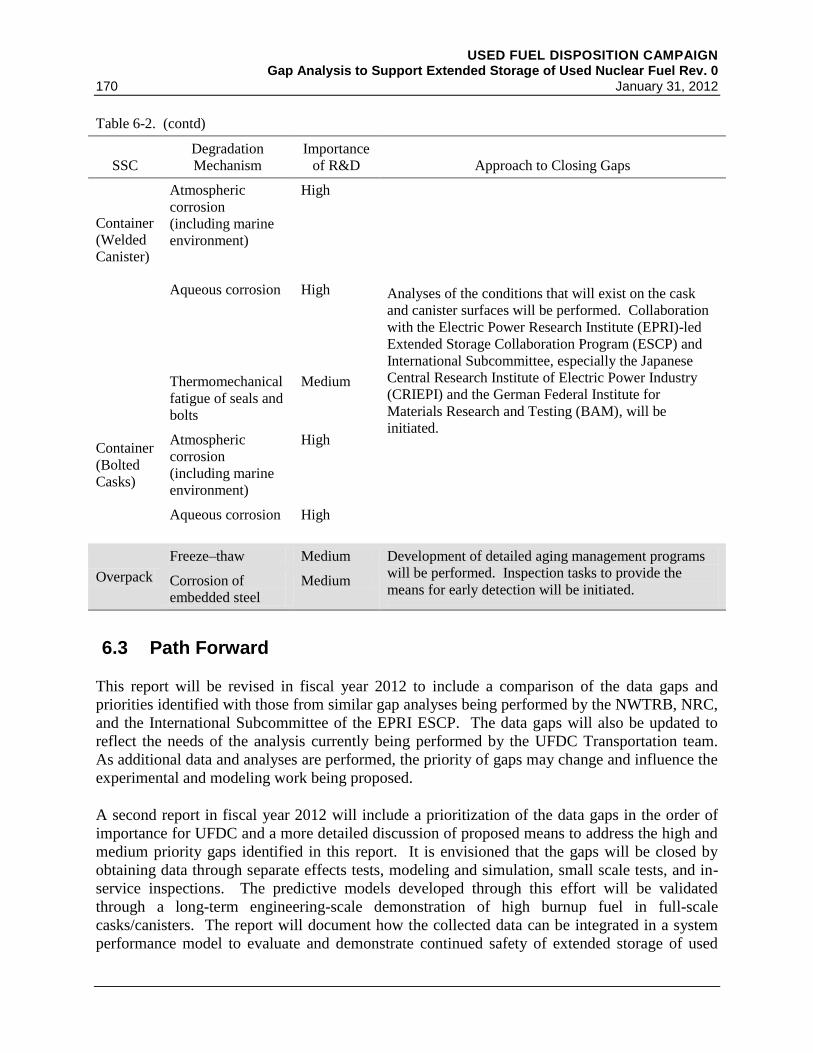
USED FUEL DISPOSITION CAMPAIGN Gap Analysis to Support Extended Storage of Used Nuclear Fuel Rev. 0
170 January 31, 2012
Table 6-2. (contd)
SSC
Degradation
Mechanism
Importance
of R&D
Approach to Closing Gaps
Container
(Welded
Canister)
Atmospheric
corrosion
(including marine
environment)
High
Analyses of the conditions that will exist on the cask
and canister surfaces will be performed. Collaboration
with the Electric Power Research Institute (EPRI)-led
Extended Storage Collaboration Program (ESCP) and
International Subcommittee, especially the Japanese
Central Research Institute of Electric Power Industry
(CRIEPI) and the German Federal Institute for
Materials Research and Testing (BAM), will be
initiated.
Aqueous corrosion High
Container
(Bolted
Casks)
Thermomechanical
fatigue of seals and
bolts
Medium
Atmospheric
corrosion
(including marine
environment)
High
Aqueous corrosion High
Overpack
Freeze–thaw Medium Development of detailed aging management programs
will be performed. Inspection tasks to provide the
means for early detection will be initiated. Corrosion of
embedded steel
Medium
6.3 Path Forward
This report will be revised in fiscal year 2012 to include a comparison of the data gaps and
priorities identified with those from similar gap analyses being performed by the NWTRB, NRC,
and the International Subcommittee of the EPRI ESCP. The data gaps will also be updated to
reflect the needs of the analysis currently being performed by the UFDC Transportation team.
As additional data and analyses are performed, the priority of gaps may change and influence the
experimental and modeling work being proposed.
A second report in fiscal year 2012 will include a prioritization of the data gaps in the order of
importance for UFDC and a more detailed discussion of proposed means to address the high and
medium priority gaps identified in this report. It is envisioned that the gaps will be closed by
obtaining data through separate effects tests, modeling and simulation, small scale tests, and in-
service inspections. The predictive models developed through this effort will be validated
through a long-term engineering-scale demonstration of high burnup fuel in full-scale
casks/canisters. The report will document how the collected data can be integrated in a system
performance model to evaluate and demonstrate continued safety of extended storage of used

USED FUEL DISPOSITION CAMPAIGN Gap Analysis to Support Extended Storage of Used Nuclear Fuel Rev. 0 January 31, 2012 171
nuclear fuel. The report will also include the necessary quality assurance requirements and
implementation plans.
In fiscal year 2012, testing and modeling of the gaps identified as high priority will begin,
including continuing the cladding ring compression tests at ANL and initiating testing to
establish the link between unirradiated and irradiated cladding.

USED FUEL DISPOSITION CAMPAIGN Gap Analysis to Support Extended Storage of Used Nuclear Fuel Rev. 0
172 January 31, 2012

USED FUEL DISPOSITION CAMPAIGN Gap Analysis to Support Extended Storage of Used Nuclear Fuel Rev. 0 January 31, 2012 173
7. REFERENCES
10 CFR Part 20. Standards for Protection Against Radiation. U.S. Nuclear Regulatory
Commission, Washington, D.C.
10 CFR Part 50. Domestic Licensing of Production and Utilization Facilities. U.S. Nuclear
Regulatory Commission, Washington, D.C.
10 CFR Part 51. Environmental Protection Regulations for Domestic Licensing and Related
Regulatory Functions. U.S. Nuclear Regulatory Commission, Washington, D.C.
10 CFR Part 71. Packaging and Transportation of Radioactive Material. U.S. Nuclear
Regulatory Commission, Washington, D.C.
10 CFR Part 72. Licensing Requirements for the Independent Storage of Spent Nuclear Fuel and
High-Level Radioactive Waste. U.S. Nuclear Regulatory Commission, Washington, D.C.
ACI 201.2R-67. 1967. Guide to Durable Concrete. American Concrete Institute, Farmington,
Michigan.
ACI 209 R-92. 1992. Prediction of Creep, Shrinkage and Temperature Effects in Concrete
Structures. American Concrete Institute, Farmington, Michigan.
ACI 301-66. 1966. Standard Specifications Structural Concrete for Buildings. American
Concrete Institute, Farmington, Michigan.
ACI 318-63. 1963. Building Code Requirements for Reinforced Concrete. American Concrete
Institute, Farmington, Michigan.
ACI 349-85. 1985. Code Requirements for Nuclear Safety Related Concrete Structures.
American Concrete Institute, Farmington, Michigan.
Aida T, T Hara, and Y Kumanao. 2010. Operating Experience in Spent Fuel Storage Casks.
IAEA-CN-178/KN27, Session 10B, Japan 1. http://www-ns.iaea.org/meetings/rw-
summaries/vienna-2010-mngement-spent-fuel.htm.
Aleshin Y, C Beard, G Mangham, D Mitchell, E Malek, and M Young. 2010. The Effect of
Pellet and Local Power Variations on PCI Margin. In Proceedings of the 2010 LWR Fuel
Performance Meeting, Top Fuel/WRFPM, p. 427. American Nuclear Society, La Grange Park,
Illinois.
Alonso C and L Fernandez. 2004. Dehydration and Rehydration Processes of Cement Paste
Exposed to High Temperature Environments. Journal of Materials Science 39:3015-3024.

USED FUEL DISPOSITION CAMPAIGN Gap Analysis to Support Extended Storage of Used Nuclear Fuel Rev. 0
174 January 31, 2012
ANSI/ANS8.1-1998. 1998. Nuclear Criticality Safety in Operations with Fissionable Material
Outside Reactors. American National Standards Institute, Washington, D.C., and American
Nuclear Society, La Grange Park, Illinois.
Aomi M, T Baba, T Miyashito, K Kaminura, T Yasuda, and Y Shinohara. 2008. Evaluation of
Hydride Reorientation Behavior and Mechanical Properties for High-Burnup Fuel-Cladding
Tubes in Interim Dry Storage. J. ASTM International 5(9):Paper ID JA1101262; available
online at www.astm.org.
ASME. 2001. Rules for Inservice Inspection of Nuclear Power Plant Components. Section XI
in The 2001 ASME Boiler and Pressure Vessel Code. ASME International, Washington, D.C.
ASTM C1562-10. 2010a. Standard Guide for the Evaluation of Materials Used in Extended
Service of Interim Spent Nuclear Fuel Dry Storage Systems. American Society for Testing and
Materials, West Conshohocken, Pennsylvania.
ASTM C227-10. 2010b. Standard Test Method for Potential Alkali Reactivity of Cement-
Aggregate Combinations (Mortar-Bar Method). American Society for Testing and Materials,
American Society for Testing and Materials, West Conshohocken, Pennsylvania.
ASTM A887-89. 2009. Standard Specification for Borated Stainless Steel Plate, Sheet, and
Strip for Nuclear Application. American Society for Testing and Materials, West
Conshohocken, Pennsylvania.
ASTM C1553-08. 2008a. Standard Guide for Drying Behavior of Spent Nuclear Fuel.
American Society for Testing and Materials, West Conshohocken, Pennsylvania.
ASTM C295-08. 2008b. Standard Guide for Petrographic Examination of Aggregates for
Concrete. American Society for Testing and Materials, West Conshohocken, Pennsylvania.
ASTM C1671-07. 2007a. Standard Practice for Qualification and Acceptance of Boron Based
Metallic Neutron Absorbers for Nuclear Criticality Control for Dry Cask Storage Systems and
Transportation Packaging. American Society for Testing and Materials, West Conshohocken,
Pennsylvania.
ASTM B811-02. 2007b. Standard Specification for Wrought Zirconium Alloy Seamless Tubes
for Nuclear Reactor Fuel Cladding. American Society for Testing and Materials, West
Conshohocken, Pennsylvania.
Bennett P and T Karlsen. 2010. In-Core Corrosion Monitoring in the Halden Test Reactor. In
Corrosion Monitoring in Nuclear Systems - Research and Applications: (EFC 56), S Ritter and
A Molander (eds), Maney Publishing, Boston, Massachusetts.

USED FUEL DISPOSITION CAMPAIGN Gap Analysis to Support Extended Storage of Used Nuclear Fuel Rev. 0 January 31, 2012 175
Bertero VV and M Polivka. 1972. Influence of Thermal Exposures on Mechanical
Characteristics of Concrete. ACI Special Publication SP34, American Concrete Institute,
Detroit, Michigan.
Billone M, Y Yan, T Burtseva, and R Daum. 2008. Cladding Embrittlement during Postulated
Loss-of-Coolant Accidents. NUREG/CR-6967, U.S. Nuclear Regulatory Commission,
Washington, D.C. ML082130389 at http://www.nrc.gov/reading-rm/adams.html.
Blanchard DC and AH Woodcock. 1980. The Production, Concentration, and Vertical
Distribution of Sea-Salt Aerosol. Annals of the New York Academy of Sciences 338:330-347.
Bosch RW and WF Bogaerts. 2010. Introduction to Different Electrochemical Corrosion
Monitoring Techniques. In Corrosion Monitoring in Nuclear Systems – Research and
Applications (EFC 56), S Ritter and A Molander (eds), Maney Publishing, Boston,
Massachusetts.
BSC. 2004a. Clad Degradation – FEPs Screening Arguments. ANL-WIS-MD-000008,
REV 02, Bechtel SAIC Co. LLC, Las Vegas, Nevada.
BSC. 2004b. CSNF Waste Form Degradation: Summary Abstraction. ANL-EBS-MD-000015,
REV 02. Bechtel SAIC Co. LLC, Las Vegas, Nevada.
Burtseva TA, Y Yan, and MC Billone. 2010. Radial-Hydride-Induced Embrittlement of High-
Burnup ZIRLO Cladding Exposed to Simulated Drying Conditions. ANL letter report to NRC,
June 20, 2010. ML101620301 at http://www.nrc.gov/reading-rm/adams/web-based.html.
Carter JT, AJ Luptak, and J Gastelum. 2011. Fuel Cycle Potential Waste Inventory for
Disposition. FCR&D-USED-2010-000031 Rev 3, U.S. Department of Energy Office of Nuclear
Energy, Washington, D.C.
Case JT, S Peer, E Gallaher, and R Zoughi. 2004. Microwave Reflection Properties of Concrete
Periodically Exposed to Chloride Solution of 3% Salinity and Compression Force. IEEE
Transactions on Instrumentation and Measurement 53(4):1000-1004.
Caseres L and TS Mintz. 2010. Atmospheric Stress Corrosion Cracking Susceptibility of
Welded and Unwelded 304, 304L, and 316L Austenitic Stainless Steels Commonly Used for Dry
Cask Storage Containers Exposed to Marine Environments. NUREG/CR-7030, U.S. Nuclear
Regulatory Commission, Washington, D.C.
Chan SYN, G-F Peng, and JKW Chan. 1996. “Comparison Between High Strength Concrete
and Normal Strength Concrete Subjected to High Temperature.” Materials and Structures
29:616-619, RILEM, Cachan, France.

USED FUEL DISPOSITION CAMPAIGN Gap Analysis to Support Extended Storage of Used Nuclear Fuel Rev. 0
176 January 31, 2012
Chao CK, KC Yang, and CC Tseng. 2008. “Rupture of Spent Fuel Zircaloy Cladding in Dry
Storage Due to Delayed Hydride Cracking.” Nuclear Engineering and Design 238:124-129.
Chin BA, MA Khan, and J Tarn. 1986. Deformation and Fracture Map Methodology for
Predicting Cladding Behavior During Dry Storage. PNL-5998, Pacific Northwest Laboratory,
Richland, Washington.
Christensen A. 2008. Cask Assessment During 2008. Engineering Design File 9069, INTEC-
2707, Idaho National Laboratory, Idaho Falls, Idaho.
Claerbout J. 2000. Acoustic Daylight Imaging: Introduction to the Underlying Concept: A
propect for the instrumented oil field. Stanford Exploration Project, 2000.
http://sepwww.stanford.edu/sep/jon/eqcor/paper_html/.
Clark JN. 1982. The Detection of Creep Failure at Welds by Acoustic Emission. British
Journal of Nondestructive Testing 25:9-21.
Cox B, F Garzarolli, A Strasser, and P Rudling. 2006. Structural Behavior of Fuel and Fuel
Channel Components. Advanced Nuclear Technology International, Surahammar, Sweden.
Dag A, L Hallstadius, A Enruca, and S Helmersson. 2010. Westinghouse New BWR Fuel –
Towards the Flawless Target. In Proceedings of the 2010 LWR Fuel Performance Meeting, Top
Fuel/WRFPM, p. 532. American Nuclear Society, La Grange Park, Illinois.
Daum RS, S. Majumdar, and MC Billone. 2008. Experimental and Analytical Investigation of
the Mechanical Behavior of High-Burnup Zircaloy-4 Fuel Cladding. Journal of ASTM
International 5(5): Paper ID JAI101209, available online at www.astm.org.
Daum RS, S Majumdar, YY Liu, and MC Billone. 2006. Radial-hydride Embrittlement of
High-burnup Zircaloy-4 Fuel Cladding. Journal of Nuclear Science and Technology 43(9):1-14.
Paper 4309O.
Delegard CH, MR Elmore, KJ Geelhood, MA Lilga, WG Luscher, GT MacLean, JK Magnuson,
RT Pagh, SG Pitman, and RS Wittman. 2009. Final Report-Evaluation of Chemical Effects
Phenomena in Post-LOCA Coolant. NUREG/CR-6988, U.S. Nuclear Regulatory Commission,
Washington, D.C.
Dominion. 2002. Application for Renewed ISFSI Site-Specific License – Surry, Independent
Spent Fuel Storage Installation. Virginia Electric and Power Company, Richmond, Virginia.
Einziger RE and C Beyer. 2007. Characteristics and Behaviour of High Burnup Fuel that May
Affect the Containment Source Terms for Cask Accidents. Nuclear Technology 159:134-146.

USED FUEL DISPOSITION CAMPAIGN Gap Analysis to Support Extended Storage of Used Nuclear Fuel Rev. 0 January 31, 2012 177
Einziger RE, HC Tsai, MC Billone, and BA Hilton. 2003. Examination of Spent PWR Fuel
Rods After 15 Years in Dry Storage. Nuclear Technology 144:186-200.
EPRI. 2010a. Impacts Associated with Transfer of Spent Nuclear Fuel from Spent Fuel Storage
Pools to Dry Storage After Five Years of Cooling. TR-1021049, Electric Power Research
Institute, Palo Alto, California.
EPRI. 2010b. Industry Spent Fuel Storage Handbook. TR-102048, Electric Power Research
Institute, Palo Alto, California.
EPRI. 2010c. Transportation of Commercial Spent Nuclear Fuel Regulatory Issues Resolution.
TR-1016637, Electric Power Research Institute, Palo Alto, California.
EPRI. 2008. Recommendations for an Effective Program to Control the Degradation of Buried
Piping. TR-1016456, Electric Power Research Institute, Charlotte, North Carolina.
EPRI. 2006. Recovery of Irradiation Damage by Post-Irradiation Thermal Annealing:
Relevance to Hydrogen Solubility and Dry Storage Issues. TR-1013446, Electric Power
Research Institute, Palo Alto, California.
EPRI. 2005. Handbook on Neutron Absorber Materials for Spent Nuclear Fuel Applications.
EPRI, Palo Alto, CA: 2005. TR-1011818EPRI. 2002a. Dry Cask Storage Characterization
Project. TR-1002882, Electric Power Research Institute, Palo Alto, California.
EPRI. 2002a. Dry Cask Storage Characterization Project. TR-1002882, Electric Power
Research Institute, Palo Alto, California.
EPRI. 2002b. Technical Bases for Extended Dry Storage of Spent Nuclear Fuel. TR-1003416,
Electric Power Research Institute, Palo Alto, California.
EPRI. 1999. Cold Demonstration of a Spent Nuclear Fuel Dry Transfer System. TR-113530,
Electric Power Research Institute, Palo Alto, California.
EPRI. 1998. Data Needs for Long-Term Dry Storage of LWR Fuel. TR-108757, Electric Power
Research Institute, Palo Alto, California.
EPRI. 1995. Dry Transfer System for Spent Fuel: Project Report, A System Designed to
Achieve the Dry Transfer of Bare Spent Fuel Between Two Casks. TR-105570, Electric Power
Research Institute, Palo Alto, California.
EPRI. 1994. Class I Structures License Renewal Industry Report: Revision 1. TR-103842,
Electric Power Research Institute, Palo Alto, California.
EPRI. 1990. NUHOMS Modular Spent Fuel Storage System: Performance Testing. EPRI NP-
6941, Electric Power Research Institute, Palo Alto, California.

USED FUEL DISPOSITION CAMPAIGN Gap Analysis to Support Extended Storage of Used Nuclear Fuel Rev. 0
178 January 31, 2012
EPRI. 1989. An Independent Spent-Fuel Storage Installation at Surry Station: Design and
Operation. EPRI NP-6032, Electric Power Research Institute, Palo Alto, California.
Farage MCR, J Secombe, and C Galle. 2003. Rehydration and Microstructure of Cement Paste
After Heating at Temperatures up to 300C. Cement and Concrete Research 33:1047-1056.
Ferry C, C Poinssot, V Broudic, C Cappelaere, L Desgranges, P Garcia, C Jegou, P Lovera,
P Marimbeau, J-P Piron, A Poulesquen, D Roudil, J-M Gras, and P Bouffioux. 2005. Synthesis
on the Spent Fuel Long Term Evolution. CEA-R-6084, Commissariat À L’Énergie Atomique,
Paris, France.
Garde AM, GP Smith, and RC Pirek. 1996. Effects of Hydride Precipitate Localization and
Neutron Fluence on the Ductility of Irradiated Zircaly-4. In Zirconium in the Nuclear Industry:
Eleventh International Symposium, ER Bradley and GP Sabol (eds). ASTM STP 1295, pp. 407-
428. American Society for Testing and Materials, Philadelphia, Pennsylvania.
Garde AM. 1989. Effects of Irradiation and Hydriding on the Mechanical Properties of
Zircaloy-4 at High Fluence. In Zirconium in the Nuclear Industry: Eighth International
Symposium, LFP VanSwam and CM Eucken (eds), ASTM STP 1023, pp. 548-569. American
Society for Testing and Materials, Philadelphia, Pennsylvania.
Garzarolli F, R Adamson, and P Rudling. 2010. Optimization of BWR Fuel Rod Cladding
Condition for High Burnups. In Proceedings of the 2010 LWR Fuel Performance Meeting, Top
Fuel/WRFPM, p. 468. American Nuclear Society, La Grange Park, Illinois.
Gilbert ER, CE Beyer, EP Simonen, and PG Medvedev. 2002. Update of CSFM Creep and
Creep Rupture Models for Determining Temperature Limits for Dry Storage of Spent Fuel.
Presentation to the International Congress on Advanced Nuclear Power Plants (ICAPP) ANS
Embedded Topical Meeting, June 9-13, 2002, Hollywood, Florida.
Goll W, H Spilker, and EH Toscano. 2001. Short-Time Creep and Rupture Tests on High
Burnup Fuel Rod Cladding. Journal of Nuclear Materials 289:247-253.
Guenther RJ, DE Blahnik, TK Campbell, UP Jenquin, JE Mendel, LE Thomas, and
CK Thornhill. 1988. Characterization of Spent Fuel Approved Testing Material −ATM-106,
PNL-5109-106, Pacific Northwest Laboratory, Richland, Washington.
Hanson BD. 1998. The Burnup Dependence of Light Water Reactor Spent Fuel Oxidation.
PNNL-11929, Pacific Northwest National Laboratory, Richland, Washington.
Hanson BD, RC Daniel, AM Casella, RS Wittman, W Wu, PJ MacFarlan, and RW Shimskey.
2008. Fuel-In-Air FY07 Summary Report. PNNL-17275, Rev. 1, Pacific Northwest National
Laboratory, Richland, Washington.

USED FUEL DISPOSITION CAMPAIGN Gap Analysis to Support Extended Storage of Used Nuclear Fuel Rev. 0 January 31, 2012 179
Harris DO and HL Dunegan. 1974. Continuous Monitoring of Fatigue-crack Growth by
Acoustic Emission Techniques. Experimental Mechanics 14:71-81.
Holston AA, V Grigoriev, G Lysell, R Källström, B Johansson, L Hallstadius, G Zhou,
I Arimescu, and M Lloret. 2010. A Combined Approach to Predict the Sensitivity of Fuel
Cladding to Hydrogen-Induced Failures during Power Ramps. In Proceedings of the 2010 LWR
Fuel Performance Meeting, Top Fuel/WRFPM, p. 167. American Nuclear Society, La Grange
Park, Illinois.
Holtec. 2002. Final Safety Analysis Report for the Holtec International Storage, Transport, and
Repository Storage Cask System (HI-STAR 100 System). Revision 1. Docket 72-1108. HI-
2012610, Holtec International, Marlton, New Jersey.
Holtec. 2000. Final Safety Analysis Report for the HI-STORM 100 Cask System, USNRC
Docket No. 72-1014, Holtec Report Number HI-2002444. Holtec International, Marlton,
New Jersey.
Huang FH and WJ Mills. 1991. Delayed Hydride Cracking Behavior for Zircaloy-2 Tubing.
Metallurgical Transactions A 22A:2049-2060.
Huntsman JM. 2006. Huntsman, Hatch: Utahns Can Deliver Final nail to PFS. Press release,
Office of the Governor, Salt Lake City, Utah. http://www.deq.utah.gov/Issues/
no_high_level_waste/documents/pdocs/PFS.pdf.
Hutton PH, MA Friesel, and JF Dawson. 1993. Continuous AE Crack Monitoring of a
Dissimilar Metal Weldment at Limerick Unit 1. NUREG/CR-5963, U.S. Nuclear Regulatory
Commission, Washington, D.C.
Hutton PH, JF Dawson, MA Friesel, JC Harris, and RA Pappas. 1984. Acoustic Emission
Monitoring of Hot Functional Testing: Watts Bar Unit 1 Nuclear Reactor. NUREG/CR-3693,
PNL-5022, Nuclear Regulatory Commission, Washington, D.C.
IAEA. 2007. Assessment and Management of Ageing of Major Nuclear Power Plant
Components Important to Safety: PWR Vessel Internals. IAEA-TECDOC-1557, International
Atomic Energy Agency, Vienna, Austria.
IAEA. 2004. Delayed Hydride Cracking in Zirconium Alloys in Pressure Tube Nuclear
Reactors. IAEA-TECDOC-1410, International Atomic Energy Agency, Vienna, Austria.
IAEA. 1997. Assessment and Management of Ageing of Major Nuclear Power Plant
Components Important to Safety: Steam Generators. IAEA-TECDOC-981, International Atomic
Energy Agency, Vienna, Austria.
USED FUEL DISPOSITION CAMPAIGN Gap Analysis to Support Extended Storage of Used Nuclear Fuel Rev. 0
180 January 31, 2012
INL. 2005. Managing Spent Nuclear Fuel at the Idaho National Laboratory. Presentation by
TJ Hill and DL Fillmore to the NATO/IAEA Advanced Research Workshop, October 2005.
INL/CON-05-00706, Idaho National Laboratory, Idaho Falls, Idaho.
Ito K, K Kamimura, and Y Tsukuda. 2004. Evaluation of Irradiation Effect on Spent Fuel
Cladding Creep Properties. In Proceedings of the 2004 International Meeting on LWR Fuel
Performance, p. 440. American Nuclear Society, La Grange Park, Illinois.
Kain RM. 1990. Marine Atmospheric Stress Corrosion Cracking of Austenitic Stainless Steels.
Materials Performance 29(12):60-62.
Kammenzind BF, DG Franklin, HR Peters, and WJ Duffin. 1996. Hydrogen Pickup and
Redistribution in Alpha-Annealed Zircaloy-4. In Zirconium in the Nuclear Industry: Eleventh
International Symposium, ER Bradley and GP Sabol (eds), ASTM STP 1295, pp. 338-369.
American Society for Testing and Materials, Philadelphia, Pennsylvania.
Kazakov VV, AM Sutin, and PA Johnson. 2002. Sensitive Imaging of an Elastic Nonlinear
Wave Source in a Solid. Applied Physics Letters 81(4):646-648.
Kearns JJ. 1967. Terminal Solubility and Partitioning of Hydrogen in the Alpha Phase of
Zirconium, Zircaloy-2 and Zircaloy-4. Journal of Nuclear Materials 22:292-303.
Kim YS. 2009. Hydride Reorientation and Delayed Hydride Cracking of Spent Fuel Rods in
Dry Storage. Metallurgical and Materials Transactions A 40A:2867-2875.
Kim YS. 2008. Delayed Hydride Cracking of Spent Fuel Rods in Dry Storage. Journal of
Nuclear Materials 378:30-34.
Kohli R, D Stahl, V Pasupathi, AB Johnson Jr, and ER Gilbert. 1985. The Behavior of
Breached Boiling Water Reactor Fuel Rods on Long-Term Exposure to Air and Argon at 598 K.
Nuclear Technology 69:186.
Kosaki A. 2008. Evaluation Method of Corrosion Lifetime of Conventional Stainless Steel
Canister Under Oceanic Air Environment. Nuclear Engineering and Design 238(5):1233-1240.
Knoll RW and ER Gilbert. 1987. Evaluation of Cover Gas Impurities and Their Effects on the
Dry Storage of LWR Spent Fuel. PNL-6365, Pacific Northwest Laboratory, Richland,
Washington.
Kupperman DS, SH Sheen, WJ Shack, and DR Diercks. 2004. Barrier Integrity Research
Program. NUREG/CR-6861, U.S. Nuclear Regulatory Commission, Washington, D.C.
Kwun H, E Mader and K Krzywosz. 2009. Guided Wave Inspection of Nuclear Fuel Rods. In
Proceedings of the 7th International Conference on NDE in Relation to Structural Integrity for
USED FUEL DISPOSITION CAMPAIGN Gap Analysis to Support Extended Storage of Used Nuclear Fuel Rev. 0 January 31, 2012 181
Nuclear and Pressurised Components. May 12-14, 2009, Yokohama, Japan. European
Commission Joint Research Centre, Luxembourg.
Lassmann K, CT Walker, J van de Laar, and F Lindström. 1995. Modelling the High Burnup
UO2 Structure in LWR Fuel. Journal of Nuclear Materials 226:1-8.
Lee CB, DH Kim, YM Kim, YS Yang, YH Jung, YB Chun, HS Seo, YP Lee, HK Lee,
HM Kwon, DK Min, JI Kim, OH Kim, and HD Chae. 2004. Post-irradiation Examination of
High Burnup UO2 Fuel. In 2004 International Meeting on LWR Fuel Performance, p. 200.
American Nuclear Society, La Grange Park, Illinois.
Lenain JC and A Proust. 2005. Active Corrosion Detection Using Acoustic Emission.
Materials Evaluation, pp. 1023-1030. American Society for Nondestructive Testing, Columbus,
Ohio.
Lorenz RA, JL Collins, AP Malinauskas, OL Kirkland, and RL Towns. 1980. Fission Product
Release from Highly Irradiated LWR Fuel. NUREG/CR-0722, U.S. Nuclear Regulatory
Commission, Washington, D.C.
Luscher WG and KJ Geelhood. 2010. Material Property Correlations: Comparisons between
FRAPCON-3.4, FRAPTRAN 1.4, and MATPRO. NUREG/CR-7024, U.S. Nuclear Regulatory
Commission, Washington, D.C.
Malhotra VM and NJ Carino. 2004. Handbook on Nondestructive Testing of Concrete. CRC
Press, West Conshohocken, Pennsylvania.
Mardon JP, GL Garner, and PB Hoffmann. 2010. M5® a Breakthrough in Zr Alloy. In
Proceedings of the 2010 LWR Fuel Performance Meeting, Top Fuel/WRFPM, Orlando, Florida,
p. 577. American Nuclear Society, La Grange Park, Illinois.
Massie ME. 2008. Device to Transmit Critical Information from the Interior of a Spent Fuel
Cask. University of Tennessee Honors Thesis Projects.
http://trace.tennessee.edu/utk_chanhonorproj/1207.
Matheson J. 2009 (revised). Opposition to High-Level Nuclear Waste. Press release from the
office of Congressman Jim Matheson (2nd
District, Utah), South Salt Lake, Utah.
http://www.deq.utah.gov/Issues/no_high_level_waste/matheson_response.htm.
McKinnon MA and ME Cunningham. 2003. Dry Storage Demonstration for High-Burnup
Spent Nuclear Fuel – Feasibility Study. PNNL-14390, Pacific Northwest National Laboratory,
Richland, Washington.
McKinnon MA and VA Deloach. 1993. Spent Nuclear Fuel Storage – Performance Tests and
Demonstrations. PNL-8451, Pacific Northwest Laboratory, Richland, Washington.

USED FUEL DISPOSITION CAMPAIGN Gap Analysis to Support Extended Storage of Used Nuclear Fuel Rev. 0
182 January 31, 2012
McRae GA, CE Coleman, and BW Leitch. 2010. The First Step for Delayed Hydride Cracking
in Zirconium Alloys. Journal of Nuclear Materials 396(2010):130-143.
Michener TE, DR Rector, JM Cuta, RE Dodge, and CW Enderlin. 1995. COBRA-SFS: A
Thermal-Hydraulic Code for Spent Fuel Storage and Transportation Casks. PNL-10782, Pacific
Northwest Laboratory, Richland, Washington.
Mitchell D, A Garde, and D Davis. 2010. Optimized ZIRLO™ Fuel Performance in
Westinghouse PWRs. In Proceedings of the 2010 LWR Fuel Performance Meeting, Top
Fuel/WRFPM, Orlando, Florida, p. 107. American Nuclear Society, La Grange Park, Illinois.
Moorthy V. 1994. Acoustic Emission Behaviour During Stage II Fatigue Crack Growth in an
AISI Type 316 Austenitic Stainless Steel. Bulletin of Materials Science 17:699-715.
Murphy TL. 2006. Master's Thesis. LM-06K004, Rensselaer Polytechnic Institute, Troy,
New York.
Murty KL. 2000. The Internal Pressurization Creep of Zr Alloys for Spent-Fuel Dry Storage
Feasibility. Journal of the Minerals, Metals and Materials Society (JOM) 52:9(2000)34.
NAC. 2004. NAC-UMS, NAC Universal MPC System Final Safety Analysis Report, Rev 4.
Docket Number 72-1025, NAC International, Inc., Norcross, Georgia.
Nadakuduti J, G Chen, and R Zhougi. 2006. Semiempirical Electromagnetic Modeling of Crack
Detection and Sizing in Cement-Based Materials Using Near-Field Microwave Methods. IEEE
Transactions on Instumentation and Measurement 55(2).
Nagy PB. 1998. Fatigue Damage Assessment by Nonlinear Ultrasonic Materials
Characterization. Ultrasonics 36.
Nakatsuka M, K Sakamoto, and T Higuchi. 2010. Critical Failure Strains for Incipient Crack
Formation in the Oxide and Hydride Layers in the Outer Surface Region of Zircaloy Fuel
Cladding Tubes. In Proceedings of the 2010 LWR Fuel Performance
Meeting/TOPFUEL/WRFPM, Orlando, Florida, p. 561. American Nuclear Society, La Grange
Park, Illinois.
Nakatsuka M, K Une, K Tokunaga, and T Ohta. 2004. Mechanical Properties of High Burnup
BWR Fuel Cladding Tubes under Simulated RIA Conditions. In Proceedings of the LWR Fuel
Performance Meeting, Orlando, Florida, Paper 1017, pp. 526-535. American Nuclear Society,
La Grange Park, Illinois.
NAS. 2005. Policies Used to Shape the Private Fuel Storage Company. In Proceedings of an
International Workshop: An International Spent Nuclear Storage Facility. National Academy
of Sciences, Washington, D.C.

USED FUEL DISPOSITION CAMPAIGN Gap Analysis to Support Extended Storage of Used Nuclear Fuel Rev. 0 January 31, 2012 183
Naus DJ. 2007. Primer on Durability of Nuclear Power Plant Reinforced Concrete Structures –
A Review of Pertinent Factors. NUREG/CR-6927, U.S. Nuclear Regulatory Commission,
Washington, D.C.
Naus DJ. 2005. The Effect of Elevated Temperature on Concrete Materials and Structures – A
Literature Review, Oak Ridge National Laboratory. NUREG/CR-6900, U.S. Nuclear
Regulatory Commission, Washington, D.C.
NEI. 2011. Status of Used Nuclear Fuel Storage at U.S. Commercial Nuclear Plants. Nuclear
Energy Institute, Washington, D.C. http://www.nei.org/resourcesandstats/documentlibrary/
nuclearwastedisposal/factsheet/statusofusednuclearfuelstorage/?print=true.
NRC. 2011a. U.S. Nuclear Regulatory Commission http://www.nrc.gov/reading-rm/doc-
collections/commission/secys/2011/2011-0029scy.pdf.
NRC. 2011b. U.S. Nuclear Regulatory Commission, Washington, D.C.
http://www.nrc.gov/reading-rm/doc-collections/fact-sheets/decommissioning.html.
NRC. 2011c. Standard Review Plan for Renewal of Spent Fuel Dry Cask Storage System
Licenses and Certificates of Compliance. NUREG-1927, U.S. Nuclear Regulatory Commission,
Washington, D.C.
NRC. 2011d. U.S. Nuclear Regulatory Commission, Washington, D.C.
http://www.nrc.gov/waste/spent-fuel-storage/designs.html.
NRC. 2011e. Three Mile Island Unit-2 ISFSI – NRC Inspection Report 072-020/2011-001 and
Notice of Deviation. U.S. Nuclear Regulatory Commission, Washington, D.C.
http://pbadupws.nrc.gov/docs/ML1109/ML11097A028.pdf.
NRC. 2010a. Fuel Retrievability. In Division of Spent Fuel Storage and Transportation (SFST)
Interim Staff Guidance (ISG). SFST-ISG-2, Rev. 1, U.S. Nuclear Regulatory Commission,
Washington, D.C.
NRC. 2010b. Standard Review Plan for Spent Fuel Dry Storage Systems at a General License
Facility. NUREG-1536, Rev 1, U.S. Nuclear Regulatory Commission, Washington, D.C.
NRC. 2010c. 2010-2011 Information Digest. NUREG-1350, Volume 22, U.S. Nuclear
Regulatory Commission, Washington, D.C. http://www.nrc.gov/reading-rm/doc-
collections/nuregs/staff/sr1350/v22/sr1350v22.pdf.
NRC. 2009a. Enclosure 2: Safety Evaluation Report, Oconee, Independent Spent Fuel Storage
Installation, License Renewal. U.S. Nuclear Regulatory Commission, Washington, D.C.

USED FUEL DISPOSITION CAMPAIGN Gap Analysis to Support Extended Storage of Used Nuclear Fuel Rev. 0
184 January 31, 2012
NRC. 2009b. Safety Evaluation Report, Docket No. 71-9325, Model Number HI-STAR 180,
Package Certificate of Compliance No. 9325, Revision No. 0. U.S. Nuclear Regulatory
Commission, Washington, D.C.
NRC. 2007a. Classifying the Condition of Spent Nuclear Fuel for Interim Storage and
Transportation based on Function (formerly entitled “Damaged Fuel”). SFST-ISG-1, Rev 2,
U.S. Nuclear Regulatory Commission, Washington, D.C.
NRC. 2007b. Moderator Exclusion in Transport Packages. Staff Requirements – SECY-07-
185, December 18, 2007. U.S. Nuclear Regulatory Commission, Washington, D.C.
NRC. 2005a. Encl2 – Safety Evaluation Report to 02/25/05 Ltr D Christian, Virginia Electric
and Power Co, Issuance of Renewed Materials License No. SNM-2501, Surry Independent Spent
Fuel Storage Installation (72-1) (L23091). U.S. Nuclear Regulatory Commission, Washington,
D.C.
NRC. 2005b. Safety Evaluation Report for H.B. Robinson Independent Spent Fuel Storage
Installation, License Renewal. U.S. Nuclear Regulatory Commission, Washington, D.C.
NRC. 2003a. Cladding Considerations for the Transportation and Storage of Spent Fuel.
SFST-ISG-11, Rev 3, U.S. Nuclear Regulatory Commission, Washington, D.C.
NRC. 2003b. Moderator Exclusion Under Hypothetical Accident Conditions and
Demonstrating Subcriticality of Spent Fuel Under the Requirements of 10 CFR 71.55(e). SFST-
ISG-19, U.S. Nuclear Regulatory Commission, Washington, D.C.
NRC. 2002. Burnup Credit in the Criticality Safety Analyses of PWR Spent Fuel in Transport
and Storage Casks. SFST-ISG-8, Rev 2, U.S. Nuclear Regulatory Commission, Washington,
D.C.
NRC. 2000. Standard Review Plan for Spent Fuel Dry Storage Facilities. NUREG-1567, U.S.
Nuclear Regulatory Commission, Washington, D.C.
NRC. 1999. Spent Fuel Heat Generation in an Independent Spent Fuel Storage Installation.
Regulatory Guide 3.54, U.S. Nuclear Regulatory Commission, Washington, D.C.
NRC. 1998a. Post Accident Recovery and Compliance with 10 CFR 72.122(l). SFST-ISG-3,
U.S. Nuclear Regulatory Commission, Washington D.C.
NRC. 1998b. Confinement Evaluation. SFST-ISG-5, U.S. Nuclear Regulatory Commission,
Washington, D.C.

USED FUEL DISPOSITION CAMPAIGN Gap Analysis to Support Extended Storage of Used Nuclear Fuel Rev. 0 January 31, 2012 185
NWTRB. 2010. Evaluation of the Technical Basis for Extended Dry Storage and
Transportation of Used Nuclear Fuel. U.S. Nuclear Waste Technical Review Board, Arlington,
Virginia.
Olander D. 2009. Nuclear Fuels – Present and Future. Journal of Nuclear Materials 389:1.
Pan G, CJ Long, AM Garde, AR Atwood, JP Foster, RJ Comstock, L Hallstadius, DL Nuhfer,
and R Baranwal. 2010. Advanced Material for PWR Application: AXIOM™ Cladding. In
Proceedings of the 2010 LWR Fuel Performance Meeting, Top Fuel/WRFPM, Orlando, Florida,
p. 612. American Nuclear Society, La Grange Park, Illinois.
Pan Y-M, CS Brossia, GA Cragnolino, V Jain, O Pensado, and N Sridhar. 2001. Effect of In-
Package Chemistry on the Degradation of Vitrified High-Level Radioactive Waste and Spent
Nuclear Fuel Cladding. CNWRA-2002-01, Center for Nuclear Waste Regulatory Analyses,
San Antonio, Texas.
Puls MP. 2009. Review of the thermodynamic basis for models of delayed hydride cracking
rate in zirconium alloys. Journal of Nuclear Materials 393(2009):350-367.
Puls MP. 2005. Developments in Delayed Hydride Cracking in Zirconium Alloys. In
Proceedings of the 11th
International Conference on Fracture, Turin, Italy, March 20-25, 2005.
Innovative Learning and Training on Fracture, Torino, Italy.
Rondinella VV. 2011. Effects of Helium Build-up on Nuclear Fuel Evolution During Storage,
In Proceedings of the 13th
International High-Level Radioactive Waste Management Conference
(IHLRWMC) April 10-14, 2011, Albuquerque, New Mexico. American Nuclear Society,
La Grange Park, Illinois.
Rose JL, MK Rajana, and ET Carr. 1994. Ultrasonic Guided Wave Inspection Concepts for
Steam Generator Tubing. Materials Evauation 52:307-311.
Rothman AJ. 1984. Potential Corrosion and Degradation Mechanisms of Zircaloy™ Cladding
on Spent Nuclear Fuel in a Tuff Repository. Report Attachment 10 to MRB-0418, JUCID-
20172, Lawrence Livermore National Laboratory, Livermore, California.
Rudling P, R Adamson, B Cox, F Garzarolli, A Strasser, A Nikulina, and S Shishov. 2009.
Impact of Manufacturing Changes on Zr alloy In-Pile Performance. Advanced Nuclear
Technology International, Skultuna, Sweden.

USED FUEL DISPOSITION CAMPAIGN Gap Analysis to Support Extended Storage of Used Nuclear Fuel Rev. 0
186 January 31, 2012
Siefken LJ, EW Coryell, EA Harvego, and JK Horost. 2001. MATPRO – A Library of
Materials Properties for Light-Water-Reactor Accident Analysis. In SCDAP/RELAP5/MOD 3.3
Code Manual. NUREG/CR-6150, Vol. 4, Rev. 2, U.S. Nuclear Regulatory Commission,
Washington, D.C. Available as ML010330424 at http://www.nrc.gov/reading-rm/adams.html.
Shah VN and CJ Hookham. 1998. Long-term Aging of Light Water Reactor Concrete
Containments. Nuclear Engineering and Design 85:51-81.
Shaikh H. 2007. Evaluation of stress corrosion cracking phenomenon in an AISI type 316LN
stainless steel using acoustic emission technique. Corrosion Science 49:740-765.
Shirai K, JTani, T Arai, M Wataru, H Takeda, and T Saegusa. 2011a. SCC Evaluation Test of a
Multi-Purpose Canister. In Proceedings of the 13th
International High-Level Radioactive Waste
Management Conference (IHLRWMC) April 10-14, 2011, Albuquerque, New Mexico, pp. 824-
831. American Nuclear Society, La Grange Park, Illinois.
Shirai K, J Tani, M Wataru, T Saegusa, and C Ito. 2011b. Long-Term Containment
Performance of Test Metal Cask.. In Proceedings of the 13th
International High-Level
Radioactive Waste Management Conference (IHLRWMC) April 10-14, 2011, Albuquerque, New
Mexico, pp. 816-823. American Nuclear Society, La Grange Park, Illinois.
Simonen EP and ER Gilbert. 1988. DATING – A Computer Code for Determining Allowable
Temperatures for Dry Storage of Spent Fuel in Inert and Nitrogen Gases. PNL-6639, Pacific
Northwest Laboratory, Richland, Washington.
Simpson CJ and CE Ells. 1974. Delayed Hydrogen Embrittlement in Zircaloy-2.5 wt% Nb.
Journal of Nuclear Materials 52:289-295.
Snieder RL and K Wapenaar. 2010. Imaging with Ambient Noise. Physics Today, September
2010.
STAR-CD User Guide Version 3.20. 2004. CD adapco Group, London.
StoreFUEL. 2011. StoreFUEL 12(153):May 3, 2011.
StoreFUEL. 2010. StoreFUEL 12(140):April 6, 2010.
Sunder S and NH Miller. 1996. Oxidation of CANDU uranium oxide fuel by air in gamma
radiation at 150°C. Journal of Nuclear Materials 231:121-131.
Tani J, M Mayuzumi, and N Hara. 2009. Initiation and Propagation of Stress Corrosion
Cracking of Stainless Steel Canister for Concrete Cask Storage of Spent Nuclear Fuel.
Corrosion 65(3):187-194.

USED FUEL DISPOSITION CAMPAIGN Gap Analysis to Support Extended Storage of Used Nuclear Fuel Rev. 0 January 31, 2012 187
Tani J, M Mayuzumi, and N Hara. 2008. Stress Corrosion Cracking of Stainless Steel Canister
for Concrete Cask Storage of Spent Fuel. Journal of Nuclear Materials 379:42-47.
Toloczko MB and SM Bruemmer. 2009. Crack-Growth Response of Alloy 690 in Simulated
PWR Primary Water. In Proceedings of the 14th
International Conference on Environmental
Degradation of Materials in Nuclear Power Systems – Water Reactors, pp. 706-720. American
Nuclear Society, La Grange Park, Illinois.
Toman G and RF Gazdzinski. 1996. Evaluation of Cable Polymer Aging Through Indenter
Testing of In-Plant and Laboratory-Aged Specimens. TR-104075, Electric Power Research
Institute, Palo Alto, California.
Transnuclear, Inc. 2001. Final Safety Analysis Report for the Standardized NUHOMS
Horizontal Modular Storage System for Irradiated Nuclear Fuel. NUH-003, Revision 6,
Transnuclear West, Fremont, California.
Tsai H and MC Billone. 2003. Characterization of High-Burnup PWR and BWR Rods, and
PWR Rods after Extended Dry-Cask Storage. In Proceedings of the 2002 Nuclear Safety
Research Conference, pp. 157-168. NUREG/CP-0180, U.S. Nuclear Regulatory Commission,
Washington, D.C.
Ulrich TJ, AM Sutin, RA Guyer, and PA Johnson. 2008. Time reversal and nonlinear elastic
wave spectroscopy TR NEWS techniques. International Journal of Nonlinear Mechanics 41.
Van Nieuwenhove R and S Solstad. 2010. In-Core Fuel Performance and Material
Characterization in the Halden Reactor. IEEE Transactions on Nuclear Science 57(5):2683-
2688.
Vinogradov S and G Kidd. 2006. In Fifth International Conference on NDE in Relation to
Structural Integrity for Nuclear and Pressurised Components, M Bieth and J Whittle (eds.).
May 10-12, 2006, San Diego, California. European Commission Joint Research Centre,
Burssels, Belgium.
Völzke H and D Wolff. 2011. Safety Aspects of Long Dry Interim Cask Storage of Spent Fuel
in Germany. In Proceedings of the 13th
International High-Level Radioactive Waste
Management Conference (IHLRWMC) April 10-14, 2011, Albuquerque, New Mexico, pp. 712-
719. American Nuclear Society, La Grange Park, Illinois.
Wagner JC. 2007. Technical Work Plan for Development of Technical Data Needed to Justify
Full Burnup Credit in Criticality Safety Licensing Analyses Involving Commercial Spent Nuclear
Fuel. DOC.20070213.0002, TWP-EBS-MD-000019, Rev. 01, Sandia National Laboratories,
Las Vegas, Nevada.

USED FUEL DISPOSITION CAMPAIGN Gap Analysis to Support Extended Storage of Used Nuclear Fuel Rev. 0
188 January 31, 2012
Walter M, M Schütze, and A Rahmel. 1993. Behavior of Oxide Scales on Alloy 800H and HK
40 During Thermal Cycling. Oxidation of Metals 40(1/2).
Westinghouse. 1980. Spent Fuel Dry Storage Technology Development, Thermal Evaluation of
Sealed Storage Cask Containing Spent Fuel. AESD-TME-3050, Westinghouse Electric
Corporation, Cranberry, Pennsylvania.
Wilberg MD. 2010. TMI-2 ISFSI Concrete Evaluation of the Horizontal Storage Modeules
(HSM) and Base Mat. EDF-9516, Wiss, Janney, Elstner Associates, Inc., Northbrook, Illinois.
Winston PL. 2007. Inspection and Gamma-Ray Dose Rate Measurements of the Annulus of the
VSC-17 Concrete Spent Nuclear Fuel Storage Cask. INL/EXT-07-13129, Idaho National
Laboratory, Idaho Falls, Idaho.
Yasuda T, M Nakasuta, and K Yamashita. 1987. Deformation and Fracture Properties of
Neutron-Irradiated Recrystallized Zircaloy-2 Cladding under Uniaxial Tension. In Zirconium in
the Nuclear Industry: Seventh International Symposium. ASTM STP 939, RB Adamson and
LFP Van Swam (eds), American Society for Testing and Materials, Philadelphia, Pennsylvan

USED FUEL DISPOSITION CAMPAIGN Gap Analysis to Support Extended Storage of Used Nuclear Fuel Rev. 0 January 31, 2012 189
APPENDIX A
Independent Spent Fuel Storage Installations in the United States by License Date

USED FUEL DISPOSITION CAMPAIGN Gap Analysis to Support Extended Storage of Used Nuclear Fuel Rev. 0
190 January 31, 2012
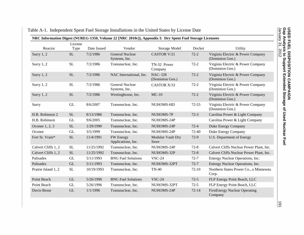
US
ED
FU
EL
DIS
PO
SIT
ION
CA
MP
AIG
N
Gap
An
aly
sis
to S
up
po
rt Exte
nd
ed
Sto
rag
e o
f Use
d N
ucle
ar F
uel
January
31, 2
012
191
Table A-1. Independent Spent Fuel Storage Installations in the United States by License Date
NRC Information Digest (NUREG-1350, Volume 22 [NRC 2010c]), Appendix I: Dry Spent Fuel Storage Licensees
Reactor
License
Type Date Issued Vendor Storage Model Docket Utility
Surry 1, 2 SL 7/2/1986 General Nuclear
Systems, Inc.
CASTOR V/21 72-2 Virginia Electric & Power Company
(Dominion Gen.)
Surry 1, 2 SL 7/2/1986 Transnuclear, Inc. TN-32Power
Company
72-2 Virginia Electric & Power Company
(Dominion Gen.)
Surry 1, 2 SL 7/2/1986 NAC International, Inc. NAC- I28
(Dominion Gen.)
72-2 Virginia Electric & Power Company
(Dominion Gen.)
Surry 1, 2 SL 7/2/1986 General Nuclear
Systems, Inc. CASTOR X/33 72-2 Virginia Electric & Power Company
(Dominion Gen.)
Surry 1, 2 SL 7/2/1986 Westinghouse, Inc. MC-10 72-2 Virginia Electric & Power Company
(Dominion Gen.)
Surry GL 8/6/2007 Transnuclear, Inc. NUHOMS-HD 72-55 Virginia Electric & Power Company
(Dominion Gen.)
H.B. Robinson 2 SL 8/13/1986 Transnuclear, Inc. NUHOMS-7P 72-3 Carolina Power & Light Company
H.B. Robinson GL 9/6/2005 Transnuclear, Inc. NUHOMS-24P 72-60 Carolina Power & Light Company
Oconee 1, 2, 3 SL 1/29/1990 Transnuclear, Inc. NUHOMS-24P 72-4 Duke Energy Company
Oconee GL 3/5/1999 Transnuclear, Inc. NUHOMS-24P 72-40 Duke Energy Company
Fort St. Vrain* SL 11/4/1991 FW Energy
Applications, Inc.
Modular Vault Dry
Store
72-9 U.S. Department of Energy
Calvert Cliffs 1, 2 SL 11/25/1992 Transnuclear, Inc. NUHOMS-24P 72-8 Calvert Cliffs Nuclear Power Plant, Inc.
Calvert Cliffs 1, 2 SL 11/25/1992 Transnuclear, Inc. NUHOMS-32P 72-8 Calvert Cliffs Nuclear Power Plant, Inc.
Palisades GL 5/11/1993 BNG Fuel Solutions VSC-24 72-7 Entergy Nuclear Operations, Inc.
Palisades GL 5/11/1993 Transnuclear, Inc. NUHOMS-32PT 72-7 Entergy Nuclear Operations, Inc.
Prairie Island 1, 2 SL 10/19/1993 Transnuclear, Inc. TN-40 72-10 Northern States Power Co., a Minnesota
Corp.
Point Beach GL 5/26/1996 BNG Fuel Solutions VSC-24 72-5 FLP Energy Point Beach, LLC
Point Beach GL 5/26/1996 Transnuclear, Inc. NUHOMS-32PT 72-5 FLP Energy Point Beach, LLC
Davis-Besse GL 1/1/1996 Transnuclear, Inc. NUHOMS-24P 72-14 FirstEnergy Nuclear Operating
Company

US
ED
FU
EL
DIS
PO
SIT
ION
CA
MP
AIG
N
Gap
An
aly
sis
to S
up
po
rt Exte
nd
ed
Sto
rag
e o
f Use
d N
ucle
ar F
uel
192
January
31, 2
012
Table A-1. (contd)
Reactor
License
Type Date Issued Vendor Storage Model Docket Utility
Arkansas Nuclear GL 12/17/1996 BNG Fuel Solutions VSC-24 72-13 Entergy Nuclear Operations, Inc.
Arkansas Nuclear GL 12/17/1996 Holtec International HI-STORM 100 72-13 Entergy Nuclear Operations, Inc.
North Anna 1, 2 SL 6/30/1998 Transnuclear, Inc. TN-32 72-16 Virginia Electric & Power
Company(Dominion Gen.)
North Anna GL 3/10/2008 Transnuclear, Inc. NUHOMS-HD 72-56 Virginia Electric & Power
Company(Dominion Gen.)
Trojan SL 3/31/1999 Holtec International HI-STORM 100 72-17 Portland General Electric Corp.
Idaho National Lab
TMI-2 Fuel Debris,
SL 3/19/1999 Transnuclear, Inc. NUHOMS-12T 72-20 U.S. Department of Energy
Susquehanna GL 10/18/1999 Transnuclear, Inc. NUHOMS-52B 72-28 PPL Susquehanna, LLC
Susquehanna GL 10/18/1999 Transnuclear, Inc. NUHOMS-61BT 72-28 PPL Susquehanna, LLC
Peach Bottom GL 6/12/2000 Transnuclear, Inc. TN-68 72-29 Exelon Generation Company, LLC
Hatch GL 7/6/2000 Holtec International HI-STAR 100 72-36 Southern Nuclear Operating, Inc
Hatch GL 7/6/2000 Holtec International HI-STORM 100 72-36 Southern Nuclear Operating, Inc
Dresden GL 7/10/2000 Holtec International HI-STAR 100 72-37 Exelon Generation Company, LLC
Dresden GL 7/10/2000 Holtec International HI-STORM 100 72-37 Exelon Generation Company, LLC
Rancho Seco SL 6/30/2000 Transnuclear, Inc. NUHOMS-24P 72-11 Sacramento Municipal Utility District
McGuire GL 2/1/2001 Transnuclear, Inc. TN-32 72-38 Duke Energy, LLC
Big Rock Point GL 11/18/2002 BNG Fuel Solutions Fuel Solutions 72-43 Entergy Nuclear Operations, Inc.
Big Rock Point GL 11/18/2002 BNG Fuel Solutions W74 72-43 Entergy Nuclear Operations, Inc.
James A. FitzPatrick GL 4/25/2002 Holtec International HI-STORM 100 72-12 Entergy Nuclear Operations, Inc.
Maine Yankee GL 8/24/2002 NAC International, Inc. NAC-UMS 72-30 Maine Yankee Atomic Power Company
Columbia Generating
Station
GL 9/2/2002 Holtec International HI-STORM 100 72-35 Energy Northwest
Oyster Creek GL 4/11/2002 Transnuclear, Inc. NUHOMS-61BT 72-15 AmerGen Energy Company, LLC.
Yankee Rowe GL 6/26/2002 NAC International, Inc. NAC-MPC 72-31 Yankee Atomic Electric
Duane Arnold GL 9/1/2003 Transnuclear, Inc. NUHOMS-61BT 72-32 Next Era Energy, Duane Arnold, LLC.
Palo Verde GL 3/15/2003 NAC International, Inc. NAC-UMS 72-44 Arizona Public Service Company

US
ED
FU
EL
DIS
PO
SIT
ION
CA
MP
AIG
N
Gap
An
aly
sis
to S
up
po
rt Exte
nd
ed
Sto
rag
e o
f Use
d N
ucle
ar F
uel
January
31, 2
012
193
Table A-1. (contd)
Reactor
License
Type Date Issued Vendor Storage Model Docket Utility
San Onofre GL 10/3/2003 Transnuclear, Inc. NUHOMS-24PT 72-41 Southern California Edison Company
Diablo Canyon 1, 2 SL 3/22/2004 Holtec International HI-STORM 100 72-26 Pacific Gas & Electric Co.
Haddam Neck GL 5/21/2004 NAC International, Inc. NAC-MPC 72-39 CT Yankee Atomic Power
Sequoyah GL 7/13/2004 Holtec International HI-STORM 100 72-34 Tennessee Valley Authority
Idaho Spent Fuel
Facility
SL 11/30/2004 Foster Wheeler
Environmental Corp.
Concrete vault 72-25
Humboldt Bay 3 SL 11/30/2005 Holtec International HI-STORM 100HB 72-27 Pacific Gas & Electric Co.
Private Fuel Storage
Facility
SL 2/21/2006 Holtec International HI-STORM 100 72-22
Browns Ferry GL 8/21/2005 Holtec International HI-STORM 100S 72-52 Tennessee Valley Authority
Joseph M. Farley GL 8/25/2005 Transnuclear, Inc. NUHOMS-32PT 72-42 Southern Nuclear Operating Co.
Millstone GL 2/15/2005 Transnuclear, Inc. NUHOMS-32PT 72-47 Dominion Generation
Quad Cities GL 12/2/2005 Holtec International HI-STORM 100S 72-53 Exelon Generation Company, LLC
River Bend GL 12/29/2005 Holtec International HI-STORM 100S 72-49 Entergy Nuclear Operations, Inc.
Fort Calhoun GL 7/29/2006 Transnuclear, Inc. NUHOMS-32PT 72-54 Omaha Public Power District
Hope Creek/Salem GL 11/10/2006 Holtec International HI-STORM 100 72-48 PSEG, Nuclear, LLC
Grand Gulf GL 11/18/2006 Holtec International HI-STORM 100S 72-50 Entergy Nuclear Operations, Inc.
Catawba GL 7/30/2007 NAC International, Inc. NAC-UMS 72-45 Duke Energy Carolinas, LLC
Indian Point GL 1/11/2008 Holtec International HI-STORM 100 72-51 Entergy Nuclear Operations, Inc.
St. Lucie GL 3/14/2008 Transnuclear, Inc. NUHOMS-HD 72-61 Florida Power and Light Company
Vermont Yankee GL 5/25/2008 Transnuclear, Inc. HI-STORM100 72-59 Entergy Nuclear Operations, Inc.
Limerick GL 8/1/2008 Transnuclear, Inc. NUHOMS-61BT 72-65 Exelon Generation Co., LLC
Seabrook GL 8/7/2008 Transnuclear, Inc. NUHOMS-HD-3PTM 72-61 NextEra Energy Seabrook, LLC
Monticello GL 9/17/2008 Transnuclear, Inc. NUHOMS-61BT 72-58 Northern States Power Co.
Kewaunee GL 9/11/2009 Transnuclear, Inc. NUHOMS-39PT 72-64 Dominion Energy Kewaunee, Inc.

USED FUEL DISPOSITION CAMPAIGN Gap Analysis to Support Extended Storage of Used Nuclear Fuel
194 January 31, 2012
USED FUEL DISPOSITION CAMPAIGN Gap Analysis to Support Extended Storage of Used Nuclear Fuel January 31, 2012 195
APPENDIX B
Dry Cask Storage in the United States by Vendor

USED FUEL DISPOSITION CAMPAIGN Gap Analysis to Support Extended Storage of Used Nuclear Fuel
196 January 31, 2012

USED FUEL DISPOSITION CAMPAIGN Gap Analysis to Support Extended Storage of Used Nuclear Fuel January 31, 2012 197
Table B-1. Dry Cask Storage in the United States by Vendor
Vendor System
Canister
Type Reactor Type Utility
Casks
4/2010
Casks
5/2011
BFS/ES
FuelSolutions VSC-24 ANO PWR Entergy 24 24
FuelSolutions W150
Big Rock
Point1,3
BWR Consumers 8 8
FuelSolutions VSC-24 Palisades PWR Entergy 18 18
FuelSolutions VSC-24 Point Beach PWR FPL 16 16
Total BFS/ES 66 66
DOE Foster Wheeler MVDS Ft. St. Vrain HTGR PS Colorado
GNB Castor V/21, X33 Surry PWR Dominion 26 26
Holtec
HI-STORM MPC-24 ANO PWR Entergy 21 22
HI-STORM MPC-32 ANO PWR Entergy 13 16
HI-STORM MPC-32 Byron PWR Exelon 0 6
HI-STORM MPC-68 Browns Ferry BWR TVA 16 25
HI-STORM MPC-68 Columbia BWR
Energy
Northwest 27 27
HI-STORM MPC-32 Diablo Canyon PWR PG&E 8 16
HI-STORM MPC-68 Dresden BWR Exelon 37 43
HI-STAR MPC-68 Dresden BWR Exelon 4 4
HI-STORM MPC-32 Farley PWR
Southern
Nuclear 10 12
HI-STORM MPC-68 Fitzpatrick BWR Entergy 15 15
HI-STORM MPC-68 Grand Gulf BWR Entergy 12 12
HI-STORM MPC-68 Hatch BWR
Southern
Nuclear 37 39
HI-STAR MPC-68 Hatch BWR
Southern
Nuclear 3 3
HI-STORM MPC-68 Hope Creek BWR PSE&G 12 16
HI-STAR MPC-80 Humboldt Bay1,3
BWR PG&E 5 5
HI-STORM MPC-32 Indian Point 13 PWR Entergy 5 5
HI-STORM MPC-32 Indian Point 2 PWR Entergy 6 10
HI-STORM MPC-68 LaSalle BWR Exelon 0 4
HI-STORM MPC-68 Quad Cities BWR Exelon 25 25
HI-STORM MPC-68 River Bend BWR Entergy 11 15
HI-STORM MPC-68 Vermont Yankee BWR Entergy 5 5
HI-STORM MPC-32 Salem PWR PSE&G 0 4
HI-STORM MPC-32 Sequoyah PWR TVA 20 26
TranStor cask
MPC-
24E/EF Trojan PWR Portland GE 34 34
Total Holtec 326 389
NAC
NAC-MPC MPC-26 Conn Yankee2,3
PWR Ct. Yankee 43 43
NAC-MPC MPC-36 Yankee Rowe2,3
PWR YAEC 16 16
NAC-UMS UMS-24 MaineYankee2,3
PWR Maine Yankee 64 64
NAC-UMS UMS-24 Catawba PWR Duke 10 16
NAC-UMS UMS-24 McGuire PWR Duke 28 28
NAC-UMS UMS-24 Palo Verde PWR APS 71 84
NAC-I28 NAC-I28 Surry PWR Dominion 2 2
Total NAC 234 253

USED FUEL DISPOSITION CAMPAIGN Gap Analysis to Support Extended Storage of Used Nuclear Fuel
198 January 31, 2012
Table B-1. (contd)
Vendor System
Canister
Type Reactor Type Utility
Casks
4/2010
Casks
4/2011
TN
NUHOMS 61BTH Brunswick BWR Progress 0 6
NUHOMS 24P Calvert Cliffs PWR Constellation 48 48
NUHOMS 32P Calvert Cliffs PWR Constellation 15 18
NUHOMS 61BT Cooper BWR NPPD 0 8
NUHOMS 24P Davis-Besse PWR FirstEnergy 3 3
NUHOMS 61BT Duane Arnold BWR FPL 10 10
NUHOMS 32PT Fort Calhoun PWR OPPD 10 10
NUHOMS 32PT Ginna PWR Constellation 0 4
NUHOMS 12T INEEL PWR DOE 29 29
NUHOMS 32PT Kewaunee PWR Dominion 2 4
NUHOMS 61BT Limerick BWR Exelon 7 12
NUHOMS 32PT Millstone PWR Dominion 11 14
NUHOMS 61BT Monticello BWR Xcel Energy 10 10
NUHOMS 32PTH North Anna PWR Dominion 7 10
NUHOMS 24PHB Oconee PWR Duke 25 34
NUHOMS 24P Oconee PWR Duke 84 84
NUHOMS 61BT Oyster Creek BWR Exelon 16 19
NUHOMS 24PTH Palisades PWR Entergy 7 7
NUHOMS 32PT Palisades PWR Entergy 11 11
NUHOMS 32PT Point Beach PWR FPL 14 14
NUHOMS 24PT Rancho Seco1 PWR SMUD 22 22
NUHOMS 24PTH Robinson PWR Progress 8 8
NUHOMS 7P Robinson PWR Progress 8 8
NUHOMS 32PTH Seabrook PWR FPL 6 6
NUHOMS 24PT1 SONGS 11,3
PWR S. Cal Edison 18 18
NUHOMS 24PT4 SONGS 2 PWR S. Cal Edison 18 22
NUHOMS 32PTH St. Lucie PWR FPL 6 11
NUHOMS 32PTH Surry PWR Dominion 9 12
NUHOMS 52B Susquehanna BWR PPL 27 27
NUHOMS 61BT Susquehanna BWR PPL 32 40
TN Metal Casks TN-32 McGuire PWR Duke 10 10
TN Metal Casks TN-32 North Anna PWR Dominion 27 27
TN Metal Casks TN-68 Peach Bottom BWR Exelon 44 49
TN Metal Casks TN-40 Prairie Island PWR Xcel Energy 26 29
TN Metal Casks TN-32 Surry PWR Dominion 26 26
Total TN 596 670
Westinghouse MC-10 MC-10 Surry PWR Dominion 1 1
Totals: 1249 1405 1 One cask storing GTCC waste is in use.
2 Connecticut Yankee has three casks storing GTCC waste; Yankee Rowe has one, and Maine Yankee
has four. 3 All spent fuel from the shutdown plant.
Source: StoreFUEL 2010, 2011.