usb i/o control boxes - mini circuits · there are no general safety precautions for using...
TRANSCRIPT

AN-49-004 Rev.: A (November 26, 2014) M149081 (R88277) File: AN-49-004(A).doc This document and its contents are the property of Mini-Circuits
User & Programming
Guide
USB I/O Control Boxes
USB-I/O-4D2RTwo 24V outputs Four TTL/LVTTL outputs Connectors: 10 pin IDC; 2x 3.81mm DC connectors
USB-I/O-16D8R8 buffered relays 16 TTL/LVTTL input/output lines Connectors: 26 pin IDC; 34 pin IDC;
USB-I/O-8DRV8 buffered relays 8 TTL/LVTTL input/output lines 8 High voltage digital inputs Connectors: 10 pin IDC; 14 pin IDC;
34 pin IDC;

Page 2 of 17 AN-49-004 Rev.: A (November 26, 2014) M149081 (R88277) File: AN-49-004(A).doc This document and its contents are the property of Mini-Circuits
Important Notice This guide is owned by Mini-Circuits and is protected by copyright, trademark and other intellectual property laws. The information in this guide is provided by Mini-Circuits as an accommodation to our customers and may be used only to promote and accompany the purchase of Mini-Circuits’ Parts. This guide may not be reproduced, modified, distributed, published, stored in an electronic database, or transmitted and the information contained herein may not be exploited in any form or by any means, electronic, mechanical recording or otherwise, without prior written permission from Mini-Circuits. This guide is subject to change, qualifications, variations, adjustments or modifications without notice and may contain errors, omissions, inaccuracies, mistakes or deficiencies. Mini-Circuits assumes no responsibility for, and will have no liability on account of, any of the foregoing. Accordingly, this guide should be used as a guideline only.
Trademarks Microsoft, Windows, Visual Basic, Visual C# and Visual C++ are registered trademarks of Microsoft Corporation. LabVIEW and CVI are registered trademarks of National Instruments Corporation. Delphi is a registered trademark of Delphi Technologies, Inc. MATLAB is a registered trademark of The MathWorks, Inc. Agilent VEE is a registered trademark of Agilent Technologies, Inc. Linux is a registered trademark of Linus Torvalds. Mac is a registered trademark of Apple Inc. Python is a registered trademark of Python Software Foundation Corporation. All other trademarks cited within this guide are the property of their respective owners. Neither Mini-Circuits nor the Mini-Circuits I/O control boxes are affiliated with or endorsed or sponsored by the owners of the above referenced trademarks. Mini-Circuits and the Mini-Circuits logo are registered trademarks of Scientific Components Corporation. Mini-Circuits 13 Neptune Avenue Brooklyn, NY 11235, USA Phone: +1-718-934-4500 Email: [email protected] Web: www.minicircuits.com

Table of Contents
Chapter 1 – General Information.................................................. 4-6 1.1 Scope of the User Guide ................................................................................4
1.2 Warranty.........................................................................................................4
1.3 Definitions.......................................................................................................4
1.4 General safety precautions.............................................................................4
1.5 Introduction.....................................................................................................4
1.6 Service and Calibration ..................................................................................5
1.7 Contact Information ........................................................................................5
1.8 Model Description........................................................................................5-6
1.8.1 Intended Applications........................................................................................5
1.8.2 Included Accessories and Options....................................................................6
1.8.3 Conformity.........................................................................................................6
1.8.4 Supported Software Environments ...................................................................7
1.9 Individual Model Features ..............................................................................7
1.9.1 USB-I/O-4D2R Features ...................................................................................7
1.9.2 USB-I/O-16D8R Features .................................................................................7
1.9.3 USB-I/O-16D8R Features .................................................................................7
Chapter 2 – Installation and setup .............................................. 8-13 2.1 Software Setup...............................................................................................8
2.2 Installation ...................................................................................................9-9
2.3 Control Box Physical Setup ..........................................................................11
2.3.1 USB-I/O-4D2R: ..........................................................................................11-11
2.3.2 USB-I/O-16D8R: ........................................................................................12-12
2.3.3 USB-I/O-8DRV:..........................................................................................13-13
Chapter 3 – Operating the Control Boxes ............................... -17 15 3.1 Starting the GUI program ........................................................................15-16
3.2 Application examples....................................................................................17
1. Chapter 1 – General Information
(Novemb contents are
Page 3 of 17 AN-49-004 Rev.: A er 26, 2014) M149081 (R88277) File: AN-49-004(A).doc This document and its the property of Mini-Circuits

1.1 Scope of the User Guide
This Manual provides general introduction, setup and installation instructions, and operating information for Mini-Circuits’ USB I/O control boxes.
1.2 Warranty See Mini-Circuits website http://www.minicircuits.com/support/ordering.html for Warranty information.
1.3 Definitions
Note: A note advises on important information you may need to insure proper operation of the equipment. There is no risk to either the equipment or the user.
A caution advises about a condition or procedure which can cause damage to the equipment (No danger to users).
Page 4 of 17 AN-49-004 Rev.: A (November 26, 2014) M149081 (R88277) File: AN-49-004(A).doc This document and its contents are the property of Mini-Circuits
A warning alerts to a possible risk to the user and steps to avoid it. Do Not proceed until you are sure you understand the warning.
1.4 General safety precautions There are no general Safety precautions for using Mini-Circuits USB&RS232 Digital Step Attenuators.
1.5 Introduction
Mini-Circuits has developed a series of USB I/O (Input/Output) control boxes. These control boxes provide a simple and effective means of controlling switches or other analog devices, multiple TTL/LVTTL devices, and even reading high voltage digital signals, all from a single standard PC or laptop computer.
Mini-Circuits provides support for the USB I/O control boxes in Windows and Linux Operating Systems, in a variety of programming environments including most lab test software using .NET assembly or ActiveX® controls which allow the user to write customized applications.
CAUTION
WARNING
Figure 1: USB-I/O-8DRV

Page 5 of 17 AN-49-004 Rev.: A (November 26, 2014) M149081 (R88277) File: AN-49-004(A).doc This document and its contents are the property of Mini-Circuits
1.6 Service and Calibration The USB-I/O control box models do not require any periodic service or calibration. The only user service possible for the models is external cleaning of the case and connectors as needed. Do not use any detergents or spray cleaning solutions to clean the control box. To clean the connectors use an alcohol solution, and to clean the case a soft, damp cloth.
1.7 Contact Information
Mini-Circuits inc. 13 Neptune Ave Brooklyn, NY 11235 Phone: 1-718-934-4500 General Fax: 1-718-332-4661 Sales / Customer Service Fax: 1-718-934-7092 [email protected] For regional offices and tech support see http://www.minicircuits.com/contact/offices.html
1.8 Model Description
Mini-Circuits’ USB I/O control boxes are USB HID devices, no driver installation required.
ActiveX and .Net objects allowing the units to be used with almost any standard control software are supplied on a CD along with a demo program to test your setup and programming samples.
The supplied software allows the control boxes to be operated from almost any 32 or 64 bit Windows computer.
The USB I/O control boxes can be controlled by a Linux computer which supports the use of USB HID.
1.8.1 Intended Applications Mini-Circuits series of USB control boxes are intended for indoor use in: - Lab and test equipment setups for both manual and automated measurements. - Control systems The models can be used by anyone familiar with the basics of electronics measurements or electronic control systems.

Page 6 of 17 AN-49-004 Rev.: A (November 26, 2014) M149081 (R88277) File: AN-49-004(A).doc This document and its contents are the property of Mini-Circuits
1.8.2 Included Accessories and Options
Accessories Available USB-I/O-4D2R USB-I/O-16D8R USB-I/O-8DRV Software CD
2.7 ft. USB cable Included with the model at no extra charge
24V power adaptor
Included with the model at no extra
charge Not used by this model
1 ft. 10 pin IDC cable Included with the model at no extra
charge
2 ft. 10 pin IDC cable
3 ft. 10 pin IDC cable
Available as additional
accessories
1 ft. 14 pin IDC cable Included with the model at no extra
charge
2 ft. 14 pin IDC cable
3 ft. 14 pin IDC cable
Not used by this model
Available as additional
accessories
1 ft. 26 pin IDC cable Included with the model at no extra
charge
2 ft. 26 pin IDC cable
3 ft. 26 pin IDC cable
Available as additional
accessories
Not used by this model
1 ft. 34 pin IDC cable Included with the model at no extra charge
2 ft. 34 pin IDC cable
3 ft. 34 pin IDC cable
Not used by this model
Available as additional accessories
4 position DC connector Included with the model at no extra
charge Not used by this model
6.8 ft. USB cable
11 ft. USB cable Available as additional accessories
US standard power cord
EU standard power cord
UK standard power cord
AUS/China standard power cord
IL standard power cord
When Ordering select one power
cord to be included at no extra charge
Not used by this model
For additional details and ordering information, click on model P/N at the top of each column.
1.8.3 Conformity Mini-Circuits Synthesized Signal Generators conform to all requirements for the
following international standards: RoHS – The models comply with EU directive for Restriction of Hazardous
Substances for 6 substances. USB 2.0 – The models meet the specifications of the Universal Serial Bus Ver.
2.0 communication standard as described by USB-IF. USB HID – The models meet the requirements for Universal Serial Bus Human
Interface Devices according to USB-IF’s Device Class Definition for Human Interface Devices firmware rev. 1.11

Page 7 of 17 AN-49-004 Rev.: A (November 26, 2014) M149081 (R88277) File: AN-49-004(A).doc This document and its contents are the property of Mini-Circuits
1.8.4 Supported Software Environments Mini-Circuits USB I/O control boxes have been tested in the following operating systems: 32 bit systems: Windows 8, Windows 7, Windows Vista, Windows XP, Windows 98 64 bit systems: Windows 8, Windows 7, Windows Vista, Linux The control boxes will work with almost any software environment that supports ActiveX or .Net including: C++, C#, CVI®, Delphi®, LabVIEW® 8 or newer, MATLAB® 7 or newer, Python, Agilent VEE®, Visual Basic®, AutoIT, Visual Studio® 6 or newer, and more
1.9 Individual Model Features
1.9.1 USB-I/O-4D2R Features • Low cost solution for automatic relay control
• Easy installation and operation
• Two DC 24V/0.375A opto-isolated relay Outputs
• Four TTL outputs with a wide range of TTL voltage
• Noise reduction circuit on digital outputs
• 24VDC Power adapter included
1.9.2 USB-I/O-16D8R Features • Low cost solution for automatic relay control
• Easy installation and operation
• 8 buffered relays (1A DC) with NC and NO outputs available for use
• 16 digital outputs (2 Bytes X 8 channels each) selectable as TTL or LVTTL
• All required operating power drawn from USB
1.9.3 USB-I/O-8DRV Features • Low cost solution for automatic relay control
• Eight DC 1A buffered relays with NC and NO output
available for use
• 8 Digital HV inputs (32V max)
• 8 digital I/O lines selectable as TTL or LVTTL
• All required operating power drawn from USB

2 Chapter 2 – Installation and setup This chapter provides information on installing the operating software and setting up Mini-Circuits’ Generators. System requirements for USB control are a computer (Pentium II or better) with support for USB HID. To run the GUI program (described in chapter 3) a Windows operating system (either 32 or 64 bits) is also needed. The USB-I/O-4D2R additionally requires a power source of 110-220V (a power cord matching the required power supply should be selected when ordering the unit).
2.1 Software Setup
If you have had any problems installing the software, we’re here to help. Try following these complete step-by-step instructions. If you still experience problems, give us a call at Mini-Circuits Worldwide Technical support. It’s (718) 934-4500 or e-mail [email protected] for North America or go to minicircuits.com/contact/worldwide_ tech_support.html for other regional numbers and addresses.
2.1.1 First save all work in progress and close any other programs that may be
running.
2.1.2 Next, insert the Mini-Circuits CD into the CD-ROM drive, or download the Full
CD software from minicircuits.com. If installing from files downloaded from the web - unzip the downloaded files to a temporary folder on your desktop or C: drive, then open the file folder you created and double-click the “Install” icon.
2.1.3 If installation from the CD does not start automatically, run install.exe from the <CD drive> root directory.
Figure 2.1.3 CD file listing window
Page 8 of 17 AN-49-004 Rev.: A (November 26, 2014) M149081 (R88277) File: AN-49-004(A).doc This document and its contents are the property of Mini-Circuits

2.2 Installation
2.2.1 The installer window should now appear. Click the “Install Now” button. Figure 2.2.1 Installer window
2.2.2 The license agreement should now appear. To proceed, click “I Agree” and
the “Continue” button.
2.2.3 The installation program will launch. Click the “OK” button to continue.
Figure 2.2.2 License agreement
Figure 2.2.3 Installation Program window
Page 9 of 17 AN-49-004 Rev.: A (November 26, 2014) M149081 (R88277) File: AN-49-004(A).doc This document and its contents are the property of Mini-Circuits

2.2.4 The destination directory window will appear. At this point it’s a good
idea to take a second and confirm the full destination address for the software. In most cases, the default will be your computer’s hard drive (C:)\program files\ Mini-Circuits USB To IO\. Click the large button at the top to continue.
Figure 2.2.4: Destination Directory window 2.2.5 The Program Group window will appear. This window allows you to select the program group under which the link for the Demo program in the Start Menu will be created. Click on “Continue” to proceed.
Figure 2.2.5: Program Group Window
2.2.6 In a second or two, your installation will be complete. Click “OK” to
close the installer.
Figure 2.2.6: Installation complete
Page 10 of 17 AN-49-004 Rev.: A (November 26, 2014) M149081 (R88277) File: AN-49-004(A).doc This document and its contents are the property of Mini-Circuits

2.3 Control Box Physical Setup 2.3.1 USB-I/O-4D2R:
2.3.1.1 Setting digital connections: a. Connect the FCBL-10-1+ wire ends, or a similar IDC cable to the digital devices to
be controlled. b. Connect the IDC plug to the IDC connector on the front of the control box. c. Connect the AC/DC-5 or similar power supply of the value needed for logic '1' (2.7V to 5V). d. If Analog outputs are required, connect them before connecting the USB cable – otherwise use the supplied USB-CBL-AB-3+ cable (or similar) to connect the control box's USB socket to the computer's USB bus.
1. Attempting to connect 24V to the digital power (5 to 2.7V) socket when connected to USB bus may cause permanent damage to the unit.
CAUTION
2. Connect power to the I/O control box in the following order: digital power, followed by 24V, then USB.
Insure the wall socket you use to power the 24V power supply is intact and connected to a proper ground.
2.3.1.2 Setting analog connections:
WARNING
a. Assemble the cable you wish to use to connect to the 24V devices - using the supplied DC connector (TBLK-4+) and your choice of wires in gauge from 30AWG to 14AWG.
b. Connect the assembled cable to the outputs at the rear of the control box. c. Connect the AC/DC-24-3W1 power adaptor (or similar power supply) to the 24V
socket at the front of the control box. d. Use the supplied USB-CBL-AB-3+ cable (or similar)to connect the control box's
USB socket to the computer's USB bus
Page 11 of 17 AN-49-004 Rev.: A (November 26, 2014) M149081 (R88277) File: AN-49-004(A).doc This document and its contents are the property of Mini-Circuits

Figure 2.3.1: USB-I/O-4D2R connections
2.3.2 USB-I/O-16D8R:
2.3.2.1 Setting digital connections: a. Set the I/O voltage selector switch to the desired voltage LVTTL (3.3V) or TTL
(5V). b. Connect the digital devices to the wire ends of FCBL-26-1+ or to similar IDC cable
and connect the cable's IDC connector to the IDC connector in the front of the control box (note current limits specified per byte and per individual line).
c. If Relay outputs are required, connect them before connecting the USB cable - otherwise use the supplied USB-CBL-AB-3+ cable (or similar) to connect the control box's USB socket to the computer's USB bus (note the LED indicator color matches your selected voltage, red=5V, yellow=3.3V).
2.3.2.2 Setting digital connections: a. Insure the power sources you are going to use are turned off. b. Connect the Analog devices to the wire ends of FCBL-34-1+ or to similar IDC
cable and connect the cable's IDC connector to the IDC connector in the rear of the control box. Note that when unpowered, the relays pass current between the Common and Normally Closed contacts of each relay.
c. Use the supplied USB-CBL-AB-3+ cable (or similar)to connect the control box's USB socket to the computer's USB bus.
Page 12 of 17 AN-49-004 Rev.: A (November 26, 2014) M149081 (R88277) File: AN-49-004(A).doc This document and its contents are the property of Mini-Circuits

Figure 2.3.2: USB-I/O-16D8R connections
2.3.3 USB-I/O-8DRV:
2.3.3.1 Setting digital connections: a. Set the I/O voltage selector switch to the desired voltage LVTTL (3.3V) or TTL (5V). b. Connect the TTL or LVTTL devices to the wire ends of FCBL-10-1+ or similar IDC cable and connect the cable's IDC connector to the 10 pin IDC connector in the front of the control box (note current limits specified per byte and per individual line). c. Connect the high voltage devices to the wire ends of FCBL-14-1+ or to similar IDC cable and connect the cable's IDC connector to the 14 pin IDC connector in the front of the control box. d. If Relay outputs are required, connect them before connecting the USB cable - otherwise use the supplied USB-CBL-AB-3+ cable or similar USB cable to connect the control box's USB socket to the computer's USB bus (note the LED indicator color, red=5V, yellow=3.3V).
2.3.3.2 Setting analog connections: a. Insure the power sources you are going to use are turned off. b. Connect the Analog devices to the wire ends of FCBL-34-1+ or to similar IDC cable and connect the cable’s IDC connector to the IDC connector in the rear of the control box. Note that when unpowered, the relays pass current between the Common and Normally Closed contacts of each relay. c. Use the supplied USB-CBL-AB-3+ cable (or similar) to connect the control box's USB socket to the computer's USB bus.
Page 13 of 17 AN-49-004 Rev.: A (November 26, 2014) M149081 (R88277) File: AN-49-004(A).doc This document and its contents are the property of Mini-Circuits

Figure 2.3.3: USB-I/O-8DRV connections
Page 14 of 17 AN-49-004 Rev.: A (November 26, 2014) M149081 (R88277) File: AN-49-004(A).doc This document and its contents are the property of Mini-Circuits

3 Chapter 3 – Operating the Control Boxes The USB I/O control boxes are supplied along with API programming objects (DLL files) to allow them to be easily controlled by most common lab test software (See Chapter 7 of the PTE Programming handbook for details) and with a Windows GUI program to transmit or receive data manually.
To start the program go to the Start menu and select All
Programs>MiniCircuits USB_To_IO (default), or go to the other destination address you selected during installation (section 2.2.5). The “MiniCircuits USB_To_IO” icon should be waiting there for you. Click on it and get started!
3.1 Starting the GUI program
3.1.1 If no control box is connected to the computer, or there is a problem
with the data connection the program will open with no unit listed in the Model name and S/N fields.
Figure 3.1.1: Device not found!
3.1.2 If multiple units are connected to the computer, the initial screen will
show a list of S/N for connected units. Select the unit you wish to start with and click OK, or click Cancel to exit the program. The program can handle up to 24 units connected simultaneously.
Figure 3.1.2: Unit selection screen
Page 15 of 17 AN-49-004 Rev.: A (November 26, 2014) M149081 (R88277) File: AN-49-004(A).doc This document and its contents are the property of Mini-Circuits
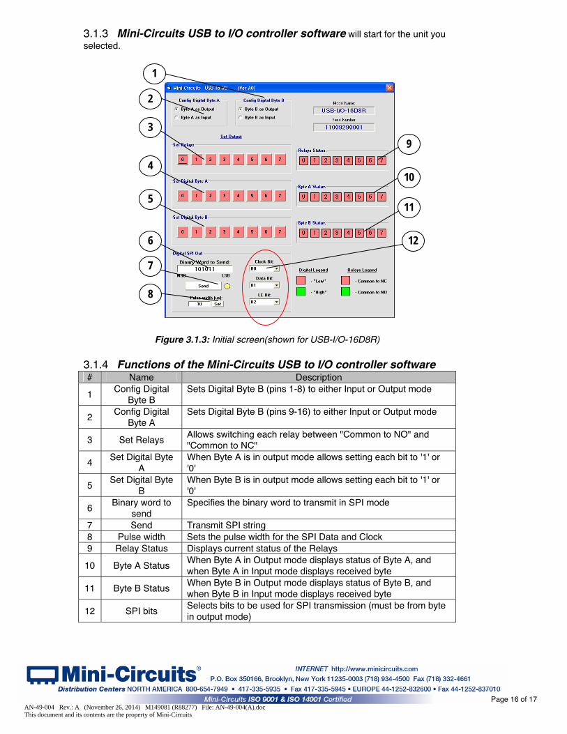
3.1.3 Mini-Circuits USB to I/O controller software will start for the unit you
selected.
Figure 3.1.3: Initial screen(shown for USB-I/O-16D8R)
3.1.4 Functions of the Mini-Circuits USB to I/O controller software
Page 16 of 17 AN-49-004 Rev.: A (November 26, 2014) M149081 (R88277) File: AN-49-004(A).doc This document and its contents are the property of Mini-Circuits
# Name Description
1 Config Digital
Byte B Sets Digital Byte B (pins 1-8) to either Input or Output mode
2 Config Digital
Byte A Sets Digital Byte B (pins 9-16) to either Input or Output mode
3 Set Relays Allows switching each relay between "Common to NO" and "Common to NC"
4 Set Digital Byte
A When Byte A is in output mode allows setting each bit to '1' or '0'
5 Set Digital Byte
B When Byte B is in output mode allows setting each bit to '1' or '0'
6 Binary word to
send Specifies the binary word to transmit in SPI mode
7 Send Transmit SPI string
8 Pulse width Sets the pulse width for the SPI Data and Clock 9 Relay Status Displays current status of the Relays
10 Byte A Status When Byte A in Output mode displays status of Byte A, and when Byte A in Input mode displays received byte
11 Byte B Status When Byte B in Output mode displays status of Byte B, and when Byte B in Input mode displays received byte
12 SPI bits Selects bits to be used for SPI transmission (must be from byte in output mode)
3
4
5
6
7
8
2
1
9
10
12
11

3.1.5 The USB I/O control models can also be operated automatically using
most common lab test software and the provided DLL files, or your own custom programs or in Linux using the supplied command codes. For more information on this see Mini-Circuits Programming Handbook on the included CD or download it from our website at http://www.minicircuits.com/support/software_download.html 3.2 Application examples
3.2.1 List of applications shown for USB-I/O-16D8R Location Description #
Bit A0 – A3 When Byte A is set to output these bits control the serial controlled attenuator DAT-31R5-SP+
1
2 Bit A7 When Byte A is set to input this bit monitors the proximity sensor
3 Relay 1 Using 24V dc power supply this relay controls a mechanical switch (such as the MSP2TA-18XL+)
4 Relay 2 Using 12V dc power supply this relay controls an RF amplifier (such as the ZRL-400+)
5 Relay 3 Using a 10V dc power supply this relay starts and stops an oscillator (such as the ZX95-310A-S+)
6 Relay 4 Using a 5V dc power supply this relay toggles a Voltage Variable attenuator (such as the ZX73-2500+) between two attenuation states.
7 Relay 5-8 These relays start and stop various devices on command using external power supplies.
As the change between input and output modes is a software function for each byte both input and output lines can be connected to a given byte and the byte cycled between input and output modes
Page 17 of 17 AN-49-004 Rev.: A (November 26, 2014) M149081 (R88277) File: AN-49-004(A).doc This document and its contents are the property of Mini-Circuits