usb hardware and pcb guidelines using stm32 mcus - … · b: usb 2.0 otg fs, that is, usb 2.0 fs...
TRANSCRIPT
IntroductionSTM32 microcontrollers include a group of products embedding a USB (Universal Serial Bus) peripheral (see table below forapplicable products). Full-speed and high-speed operations are provided through embedded and/or external PHYs (physicallayers of the open system interconnection model).
This application note gives an overview of the USB peripherals implemented on STM32 MCUs, and provides hardwareguidelines for PCB design, to ensure electrical compliance with the USB standards.
For more details, refer to the USB or OTG sections in the reference manual related to the MCU used for your application.
Table 1. Applicable products
Type Reference Series, lines, part numbers
Mic
roco
ntro
llers
Complete series STM32F2 Series, STM32L1 Series, STM32L4+ Series
Complete lines
STM32F102, STM32F103, STM32F105/107, STM32F373, STM32F401, STM32F405/415, STM32F407/417,STM32F411, STM32F412, STM32F413/423, STM32F427/437, STM32F429/439, STM32F446,STM32F469/479, STM32F7x2, STM32F7x3, STM32L0x2, STM32L0x3, STM32L4x2, STM32L4x3,STM32L4x5, STM32L4x6, STM32H743/753, STM32H750 Value line
STM32F04xxxSTM32F042C4, STM32F042C6, STM32F042F4, STM32F042F6, STM32F042G4, STM32F042G6,STM32F042K4, STM32F042K6, STM32F042T4, STM32F042T6, STM32F048C6, STM32F048G6,STM32F048T6
STM32F072xx STM32F072C8, STM32F072CB, STM32F072R8, STM32F072RB, STM32F072V8, STM32F072VB
STM32F078xx STM32F078CB, STM32F078RB, STM32F078VB
STM32F070xx STM32F070C6, STM32F070CB, STM32F070F6, STM32F070RB
STM32F302x6 STM32F302C6, STM32F302K6, STM32F302R6
STM32F302x8 STM32F302C8, STM32F302K8, STM32F302R8
STM32F302xB STM32F302CB, STM32F302RB, STM32F302VB
STM32F302xC STM32F302CC, STM32F302RC, STM32F302VC
STM32F302xD STM32F302CD, STM32F302RD, STM32F302VD, STM32F302ZD
STM32F302xE STM32F302RE, STM32F302VE, STM32F302ZE
STM32F303xB STM32F303CB, STM32F303RB, STM32F303VB
STM32F303xC STM32F303CC, STM32F303RC, STM32F303VC
STM32F303xD STM32F303CD, STM32F303RD, STM32F303VD, STM32F303ZD
STM32F303xE STM32F303RE, STM32F303VE, STM32F303ZE
STM32F74xxxSTM32F745IE, STM32F745IG, STM32F745VE, STM32F745VG, STM32F745ZE, STM32F745ZG,STM32F746BE, STM32F746BG, STM32F746IE, STM32F746IG, STM32F746NE, STM32F746NG,STM32F746VE, STM32F746VG, STM32F746ZE, STM32F746ZG
STM32F756xx STM32F756BG, STM32F756IG, STM32F756NG, STM32F756VG, STM32F756ZG
STM32F76xxx
STM32F765BI, STM32F765IG, STM32F765II, STM32F765NG, STM32F765NI, STM32F765VG,STM32F765VI, STM32F765ZG, STM32F765ZI, STM32F767BG, STM32F767BI, STM32F767IG, STM32F767II,STM32F767NG, STM32F767NI, STM32F767VG, STM32F767VI, STM32F767ZG, STM32F767ZI,STM32F768AI, STM32F769AG, STM32F769AI, STM32F769BG, STM32F769BI, STM32F769IG,STM32F769II, STM32F769NG, STM32F769NI, STM32F769SL
STM32F77xxx STM32F777BI, STM32F777II, STM32F777NI, STM32F777VI, STM32F777ZI, STM32F778AI, STM32F779AI,STM32F779BI, STM32F779II, STM32F779NI
USB hardware and PCB guidelines using STM32 MCUs
AN4879
Application note
AN4879 - Rev 4 - December 2018For further information contact your local STMicroelectronics sales office.
www.st.com
1 General information
The table below lists the main acronyms used in this document and their meanings.
Table 2. List of abbreviations and acronyms
Acronym Description
ADP Attach detection protocol
BCP Battery charging detection
EMI Electromagnetic interference
ESD Electrostatic discharge
FS Full-speed
HBM Human body model
HS High-speed
IEC International electrotechnical comission
LPM Link power management
LS Low-speed
MCU Microcontroller unit or microcontroller
OTG On-the-go
PCB Printed circuit board
PHY Physical layer
SOF Start of frame
ULPI UTMI + low-pin interface
USB Universal serial bus
UTMI USB 2.0 transceiver macrocell interface
This document applies to STM32 microcontrollers which are based on Arm® cores.
Note: Arm is a registered trademark of Arm Limited (or its subsidiaries) in the US and/or elsewhere.
AN4879General information
AN4879 - Rev 4 page 2/25
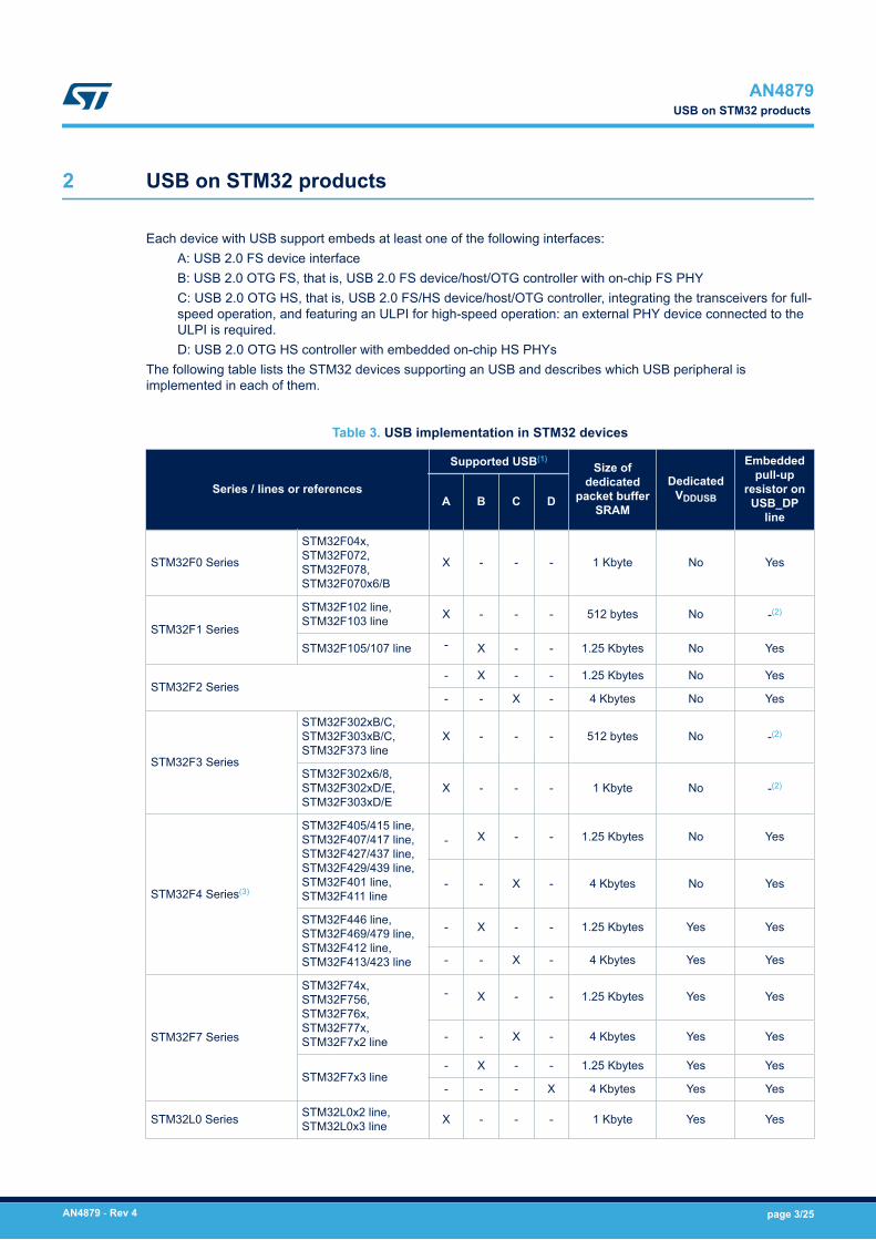
2 USB on STM32 products
Each device with USB support embeds at least one of the following interfaces:A: USB 2.0 FS device interfaceB: USB 2.0 OTG FS, that is, USB 2.0 FS device/host/OTG controller with on-chip FS PHYC: USB 2.0 OTG HS, that is, USB 2.0 FS/HS device/host/OTG controller, integrating the transceivers for full-speed operation, and featuring an ULPI for high-speed operation: an external PHY device connected to theULPI is required.D: USB 2.0 OTG HS controller with embedded on-chip HS PHYs
The following table lists the STM32 devices supporting an USB and describes which USB peripheral isimplemented in each of them.
Table 3. USB implementation in STM32 devices
Series / lines or references
Supported USB(1)Size of
dedicatedpacket buffer
SRAM
DedicatedVDDUSB
Embeddedpull-up
resistor onUSB_DP
lineA B C D
STM32F0 Series
STM32F04x,STM32F072,STM32F078,STM32F070x6/B
X - - - 1 Kbyte No Yes
STM32F1 Series
STM32F102 line,STM32F103 line X - - - 512 bytes No -(2)
STM32F105/107 line - X - - 1.25 Kbytes No Yes
STM32F2 Series- X - - 1.25 Kbytes No Yes
- - X - 4 Kbytes No Yes
STM32F3 Series
STM32F302xB/C,STM32F303xB/C,STM32F373 line
X - - - 512 bytes No -(2)
STM32F302x6/8,STM32F302xD/E,STM32F303xD/E
X - - - 1 Kbyte No -(2)
STM32F4 Series(3)
STM32F405/415 line,STM32F407/417 line,STM32F427/437 line,STM32F429/439 line,STM32F401 line,STM32F411 line
- X - - 1.25 Kbytes No Yes
- - X - 4 Kbytes No Yes
STM32F446 line,STM32F469/479 line,STM32F412 line,STM32F413/423 line
- X - - 1.25 Kbytes Yes Yes
- - X - 4 Kbytes Yes Yes
STM32F7 Series
STM32F74x,STM32F756,STM32F76x,STM32F77x,STM32F7x2 line
- X - - 1.25 Kbytes Yes Yes
- - X - 4 Kbytes Yes Yes
STM32F7x3 line- X - - 1.25 Kbytes Yes Yes
- - - X 4 Kbytes Yes Yes
STM32L0 Series STM32L0x2 line,STM32L0x3 line X - - - 1 Kbyte Yes Yes
AN4879USB on STM32 products
AN4879 - Rev 4 page 3/25
Series / lines or references
Supported USB(1)Size of
dedicatedpacket buffer
SRAM
DedicatedVDDUSB
Embeddedpull-up
resistor onUSB_DP
lineA B C D
STM32L1 Series X - - - 512 bytes No Yes
STM32L4 Series
STM32L4x2 line,STM32L4x3 line X - - - 1 Kbyte Yes Yes
STM32L4x5 line,STM32L4x6 line - X - - 1.25 Kbytes Yes Yes
STM32L4+ Series - X - - 1.25 Kbytes Yes Yes
STM32H7 Series STM32H743/753 line,STM32H750 Value line - X(4) X - 4 Kbytes Yes(5) Yes
1. X: supported.2. To be compliant with the USB 2.0 full-speed electrical specification, the USB_DP (D+) pin must be pulled up to a voltage in
the 3.0 to 3.6 V range with a 1.5 kΩ resistor.3. STM32F401/411/412/413/423 devices support only FS mode.4. USB 2.0 OTG HS device/host/OTG peripheral, supporting only full-speed operations.5. Available through VDD50USB and VDD33USB pins.
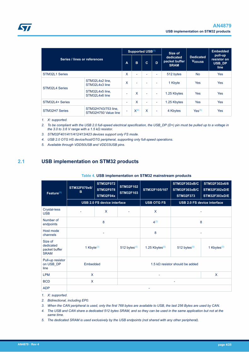
2.1 USB implementation on STM32 products
Table 4. USB implementation on STM32 mainstream products
Feature(1)
STM32F070x6/B
STM32F072
STM32F078
STM32F04x
STM32F102
STM32F103STM32F105/107
STM32F302xB/C
STM32F303xB/C
STM32F373
STM32F302x6/8
STM32F302xD/E
STM32F303xD/E
USB 2.0 FS device interface USB OTG FS USB 2.0 FS device interface
Crystal-lessUSB - X - X -
Number ofendpoints 8 4(2) 8
Host modechannels - 8 -
Size ofdedicatedpacket bufferSRAM
1 Kbyte(3) 512 bytes(4) 1.25 Kbytes(5) 512 bytes(5) 1 Kbytes(3)
Pull-up resistoron USB_DPline
Embedded 1.5 kΩ resistor should be added
LPM X - X
BCD X -
ADP -
1. X: supported.2. Bidirectional, including EP0.3. When the CAN peripheral is used, only the first 768 bytes are available to USB, the last 256 Bytes are used by CAN.4. The USB and CAN share a dedicated 512 bytes SRAM, and so they can be used in the same application but not at the
same time.5. The dedicated SRAM is used exclusively by the USB endpoints (not shared with any other peripheral).
AN4879USB implementation on STM32 products
AN4879 - Rev 4 page 4/25
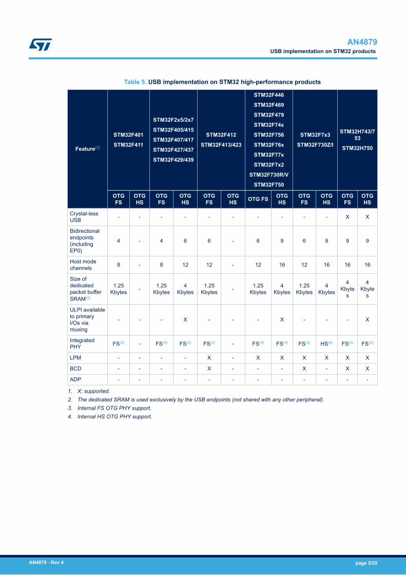
Table 5. USB implementation on STM32 high-performance products
Feature(1)
STM32F401
STM32F411
STM32F2x5/2x7
STM32F405/415
STM32F407/417
STM32F427/437
STM32F429/439
STM32F412
STM32F413/423
STM32F446
STM32F469
STM32F479
STM32F74x
STM32F756
STM32F76x
STM32F77x
STM32F7x2
STM32F730R/V
STM32F750
STM32F7x3
STM32F730Z/I
STM32H743/753
STM32H750
OTGFS
OTGHS
OTGFS
OTGHS
OTGFS
OTGHS OTG FS OTG
HSOTGFS
OTGHS
OTGFS
OTGHS
Crystal-lessUSB - - - - - - - - - - X X
Bidirectionalendpoints(includingEP0)
4 - 4 6 6 - 6 9 6 9 9 9
Host modechannels 8 - 8 12 12 - 12 16 12 16 16 16
Size ofdedicatedpacket bufferSRAM(2)
1.25Kbytes - 1.25
Kbytes4
Kbytes1.25
Kbytes - 1.25Kbytes
4Kbytes
1.25Kbytes
4Kbytes
4Kbyte
s
4Kbyte
s
ULPI availableto primaryI/Os viamuxing
- - - X - - - X - - - X
IntegratedPHY FS(3) - FS(3) FS(3) FS(3) - FS(3) FS(3) FS(3) HS(4) FS(3) FS(3)
LPM - - - - X - X X X X X X
BCD - - - - X - - - X - X X
ADP - - - - - - - - - - - -
1. X: supported.2. The dedicated SRAM is used exclusively by the USB endpoints (not shared with any other peripheral).3. Internal FS OTG PHY support.4. Internal HS OTG PHY support.
AN4879USB implementation on STM32 products
AN4879 - Rev 4 page 5/25
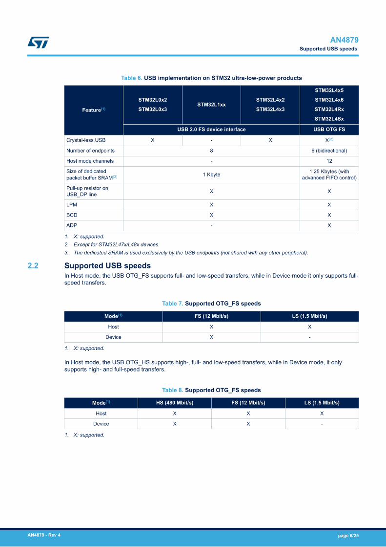
Table 6. USB implementation on STM32 ultra-low-power products
Feature(1)
STM32L0x2
STM32L0x3STM32L1xx
STM32L4x2
STM32L4x3
STM32L4x5
STM32L4x6
STM32L4Rx
STM32L4Sx
USB 2.0 FS device interface USB OTG FS
Crystal-less USB X - X X(2)
Number of endpoints 8 6 (bidirectional)
Host mode channels - 12
Size of dedicatedpacket buffer SRAM(3) 1 Kbyte 1.25 Kbytes (with
advanced FIFO control)
Pull-up resistor onUSB_DP line X X
LPM X X
BCD X X
ADP - X
1. X: supported.2. Except for STM32L47x/L48x devices.3. The dedicated SRAM is used exclusively by the USB endpoints (not shared with any other peripheral).
2.2 Supported USB speedsIn Host mode, the USB OTG_FS supports full- and low-speed transfers, while in Device mode it only supports full-speed transfers.
Table 7. Supported OTG_FS speeds
Mode(1) FS (12 Mbit/s) LS (1.5 Mbit/s)
Host X X
Device X -
1. X: supported.
In Host mode, the USB OTG_HS supports high-, full- and low-speed transfers, while in Device mode, it onlysupports high- and full-speed transfers.
Table 8. Supported OTG_FS speeds
Mode(1) HS (480 Mbit/s) FS (12 Mbit/s) LS (1.5 Mbit/s)
Host X X X
Device X X -
1. X: supported.
AN4879Supported USB speeds
AN4879 - Rev 4 page 6/25
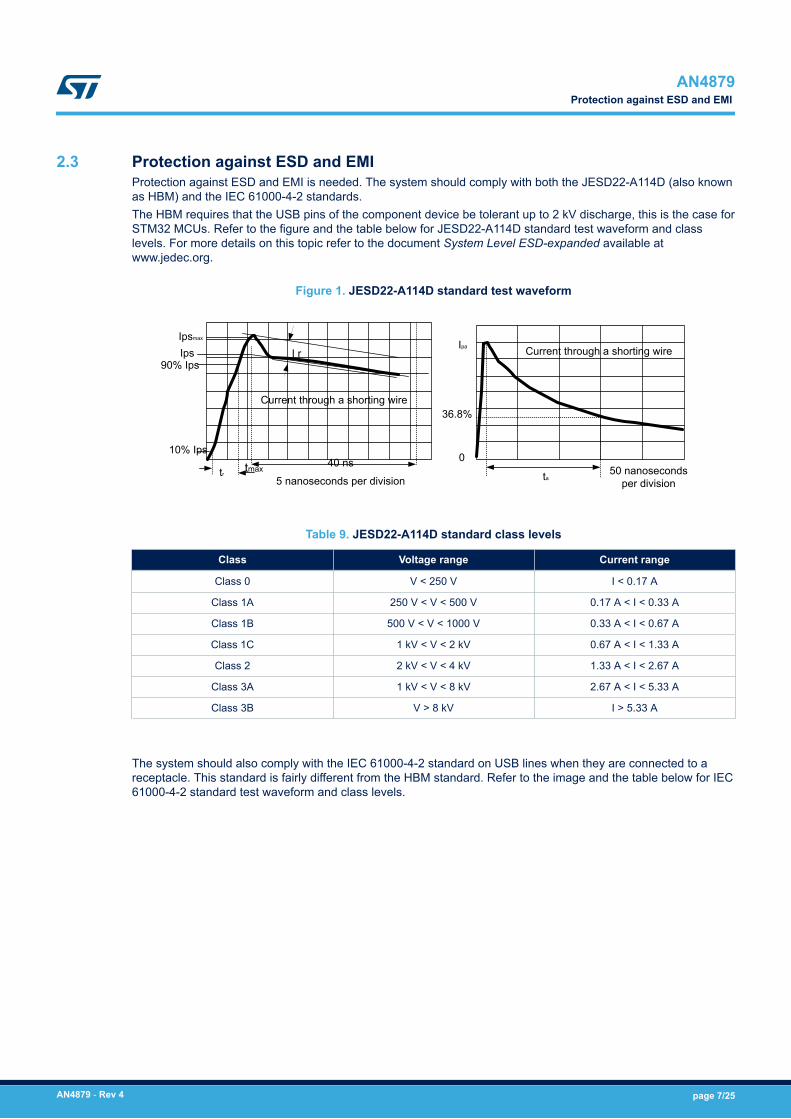
2.3 Protection against ESD and EMIProtection against ESD and EMI is needed. The system should comply with both the JESD22-A114D (also knownas HBM) and the IEC 61000-4-2 standards.The HBM requires that the USB pins of the component device be tolerant up to 2 kV discharge, this is the case forSTM32 MCUs. Refer to the figure and the table below for JESD22-A114D standard test waveform and classlevels. For more details on this topic refer to the document System Level ESD-expanded available atwww.jedec.org.
Figure 1. JESD22-A114D standard test waveform
I rIpsmax
Ips90% Ips
10% Ips
Current through a shorting wire
trtmax
5 nanoseconds per division
40 ns
Ipa
36.8%
0
ta50 nanoseconds
per division
Current through a shorting wire
Table 9. JESD22-A114D standard class levels
Class Voltage range Current range
Class 0 V < 250 V I < 0.17 A
Class 1A 250 V < V < 500 V 0.17 A < I < 0.33 A
Class 1B 500 V < V < 1000 V 0.33 A < I < 0.67 A
Class 1C 1 kV < V < 2 kV 0.67 A < I < 1.33 A
Class 2 2 kV < V < 4 kV 1.33 A < I < 2.67 A
Class 3A 1 kV < V < 8 kV 2.67 A < I < 5.33 A
Class 3B V > 8 kV I > 5.33 A
The system should also comply with the IEC 61000-4-2 standard on USB lines when they are connected to areceptacle. This standard is fairly different from the HBM standard. Refer to the image and the table below for IEC61000-4-2 standard test waveform and class levels.
AN4879Protection against ESD and EMI
AN4879 - Rev 4 page 7/25
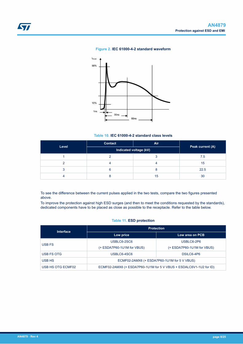
Figure 2. IEC 61000-4-2 standard waveform
Table 10. IEC 61000-4-2 standard class levels
LevelContact Air
Peak current (A)Indicated voltage (kV)
1 2 3 7.5
2 4 4 15
3 6 8 22.5
4 8 15 30
To see the difference between the current pulses applied in the two tests, compare the two figures presentedabove.To improve the protection against high ESD surges (and then to meet the conditions requested by the standards),dedicated components have to be placed as close as possible to the receptacle. Refer to the table below.
Table 11. ESD protection
InterfaceProtection
Low price Low area on PCB
USB FSUSBLC6-2SC6
(+ ESDA7P60-1U1M for VBUS)
USBLC6-2P6
(+ ESDA7P60-1U1M for VBUS)
USB FS OTG USBLC6-4SC6 DSILC6-4P6
USB HS ECMF02-2AMX6 (+ ESDA7P60-1U1M for 5 V VBUS)
USB HS OTG ECMF02 ECMF02-2AMX6 (+ ESDA7P60-1U1M for 5 V VBUS + ESDALC6V1-1U2 for ID)
AN4879Protection against ESD and EMI
AN4879 - Rev 4 page 8/25
2.4 ClockThe FS USB device/OTG requires a precise 48 MHz clock. This frequency can be generated from the internalmain PLL, or by the internal 48 MHz oscillator.In the first case the clock source must use an HSE crystal oscillator, in the second case, the synchronization forthe oscillator can be taken from:• The USB data stream itself (SOF signalization), no external resonator/ crystal is needed (this feature is only
available for devices embedding a crystal-less USB 2.0 FS device interface), or• The internal 48 MHz oscillator trimmed on LSE (not accurate enough for USB host).• MSI and LSE only for STM32L47x/L48x devices.
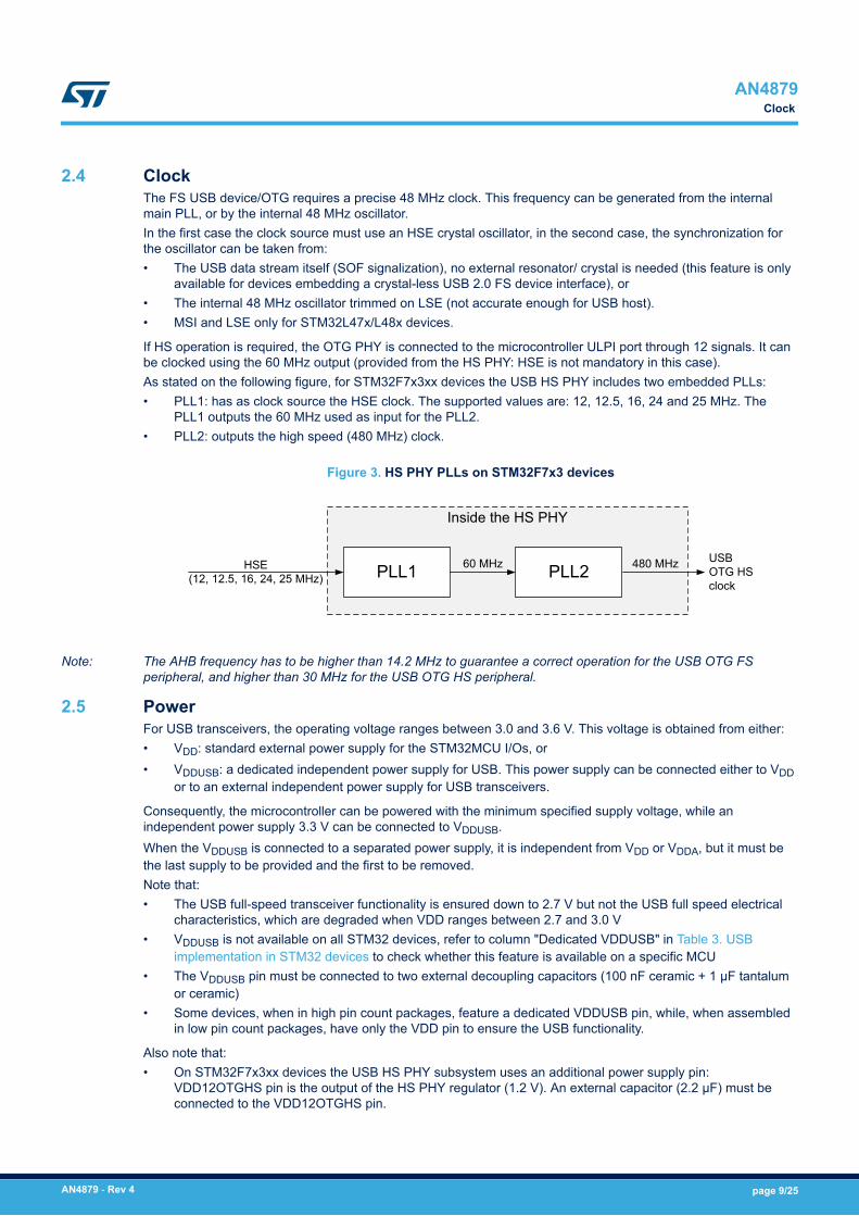
If HS operation is required, the OTG PHY is connected to the microcontroller ULPI port through 12 signals. It canbe clocked using the 60 MHz output (provided from the HS PHY: HSE is not mandatory in this case).As stated on the following figure, for STM32F7x3xx devices the USB HS PHY includes two embedded PLLs:• PLL1: has as clock source the HSE clock. The supported values are: 12, 12.5, 16, 24 and 25 MHz. The
PLL1 outputs the 60 MHz used as input for the PLL2.• PLL2: outputs the high speed (480 MHz) clock.
Figure 3. HS PHY PLLs on STM32F7x3 devices
Inside the HS PHY
PLL1 PLL260 MHz 480 MHz USBOTG HS clock
HSE(12, 12.5, 16, 24, 25 MHz)
Note: The AHB frequency has to be higher than 14.2 MHz to guarantee a correct operation for the USB OTG FSperipheral, and higher than 30 MHz for the USB OTG HS peripheral.
2.5 PowerFor USB transceivers, the operating voltage ranges between 3.0 and 3.6 V. This voltage is obtained from either:• VDD: standard external power supply for the STM32MCU I/Os, or• VDDUSB: a dedicated independent power supply for USB. This power supply can be connected either to VDD
or to an external independent power supply for USB transceivers.
Consequently, the microcontroller can be powered with the minimum specified supply voltage, while anindependent power supply 3.3 V can be connected to VDDUSB.When the VDDUSB is connected to a separated power supply, it is independent from VDD or VDDA, but it must bethe last supply to be provided and the first to be removed.Note that:• The USB full-speed transceiver functionality is ensured down to 2.7 V but not the USB full speed electrical
characteristics, which are degraded when VDD ranges between 2.7 and 3.0 V• VDDUSB is not available on all STM32 devices, refer to column "Dedicated VDDUSB" in Table 3. USB
implementation in STM32 devices to check whether this feature is available on a specific MCU• The VDDUSB pin must be connected to two external decoupling capacitors (100 nF ceramic + 1 μF tantalum
or ceramic)• Some devices, when in high pin count packages, feature a dedicated VDDUSB pin, while, when assembled
in low pin count packages, have only the VDD pin to ensure the USB functionality.
Also note that:• On STM32F7x3xx devices the USB HS PHY subsystem uses an additional power supply pin:
VDD12OTGHS pin is the output of the HS PHY regulator (1.2 V). An external capacitor (2.2 μF) must beconnected to the VDD12OTGHS pin.
AN4879Clock
AN4879 - Rev 4 page 9/25
• On STM32H7x3 devices VDD50USB can be supplied through the USB cable to generate the VDD33USB via anUSB internal regulator, making it possible to support a VDD supply different from 3.3 V. The USB regulatorcan be bypassed to supply VDD33USB directly when VDD = 3.3 V.
2.6 VBUS sensing detectionBased on the USB specification, USB device shall use VBUS sensing detection. Thus, when the host presence isdetected by the device, the device connects its pull up resistor to either D+ or D- data signal. This allows the hostto detect the device existence on the bus.There are two cases:• The USB device is bus-powered, VBUS sensing is not mandatory (USB is always connected when the
device is powered)• The device is self-powered, VBUS sensing is mandatory.
Pin PA9, a 5 V-tolerant pin, is natively dedicated to VBUS sensing. The absolute maximum ratings table of thedatasheet indicates that the 5 V-tolerant pin voltage cannot exceed VDD + 4 V. User needs to avoid the situationwhen the MCU is not powered and 5 V VBUS is connected to PA9, because it violates the condition on absolutemaximum ratings and can result in permanent damages to the device.For this purpose, it is mandatory to reduce the voltage on PA9 below 4 V. Additionally, the internal VBUSdetection block within the OTG peripheral has a current consumption, as mentioned in the STM32 datasheets:“When VBUS sensing feature is enabled, PA9 should be left at their default state (floating input), not as alternatefunction. A typical 200 μA current consumption of the embedded sensing block (current to voltage conversion todetermine the different sessions) can be observed on PA9 when the feature is enabled.”.For reliable and safe connection, use a voltage divider with a configuration limiting the voltage below 4 V.Additionally, to be detected, voltage needs to be higher than 0.7 × VDD.
AN4879VBUS sensing detection
AN4879 - Rev 4 page 10/25
3 Hardware guidelines for USB implementation
This section describes the hardware requirements for correct operation of the USB peripheral.
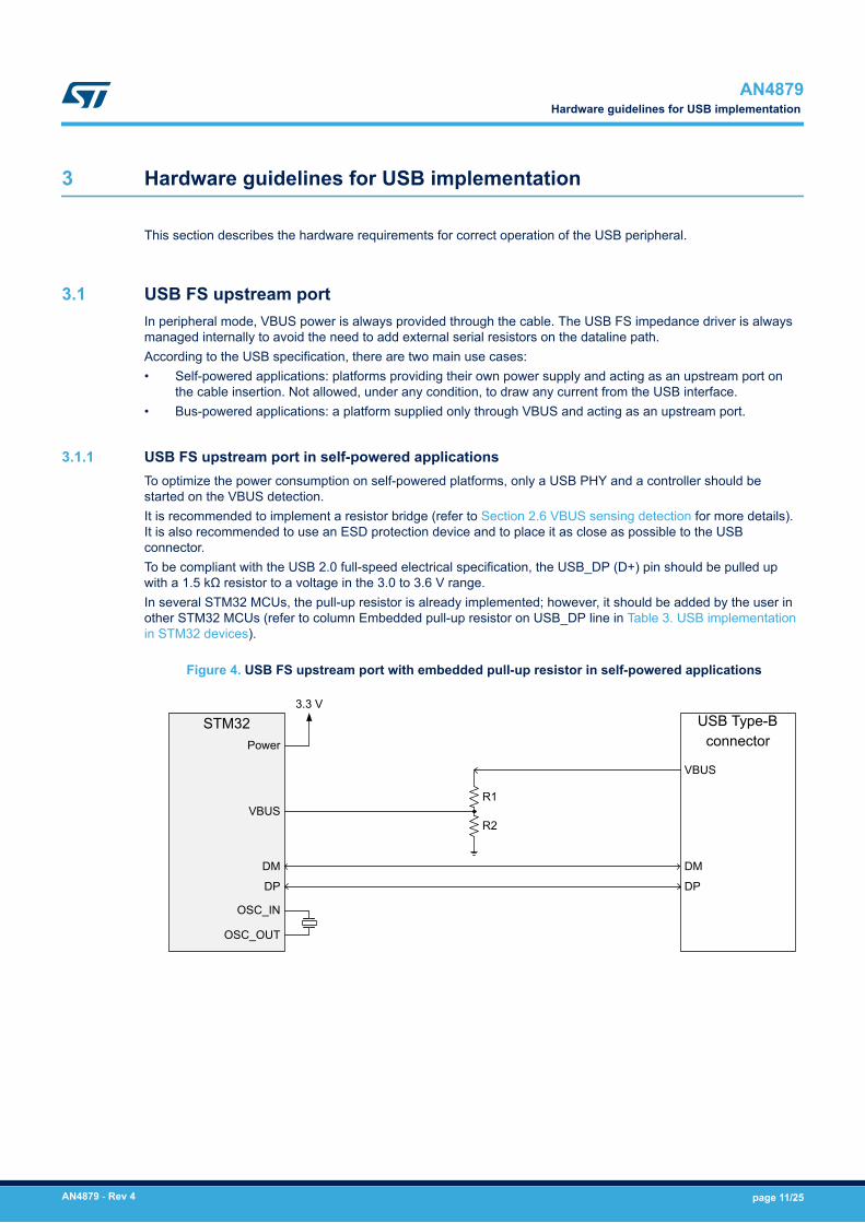
3.1 USB FS upstream portIn peripheral mode, VBUS power is always provided through the cable. The USB FS impedance driver is alwaysmanaged internally to avoid the need to add external serial resistors on the dataline path.According to the USB specification, there are two main use cases:• Self-powered applications: platforms providing their own power supply and acting as an upstream port on
the cable insertion. Not allowed, under any condition, to draw any current from the USB interface.• Bus-powered applications: a platform supplied only through VBUS and acting as an upstream port.
3.1.1 USB FS upstream port in self-powered applicationsTo optimize the power consumption on self-powered platforms, only a USB PHY and a controller should bestarted on the VBUS detection.It is recommended to implement a resistor bridge (refer to Section 2.6 VBUS sensing detection for more details).It is also recommended to use an ESD protection device and to place it as close as possible to the USBconnector.To be compliant with the USB 2.0 full-speed electrical specification, the USB_DP (D+) pin should be pulled upwith a 1.5 kΩ resistor to a voltage in the 3.0 to 3.6 V range.In several STM32 MCUs, the pull-up resistor is already implemented; however, it should be added by the user inother STM32 MCUs (refer to column Embedded pull-up resistor on USB_DP line in Table 3. USB implementationin STM32 devices).
Figure 4. USB FS upstream port with embedded pull-up resistor in self-powered applications
STM32Power
VBUS
DM
DP
OSC_IN
OSC_OUT
3.3 VUSB Type-B
connector
VBUS
DM
DP
R1
R2
AN4879Hardware guidelines for USB implementation
AN4879 - Rev 4 page 11/25
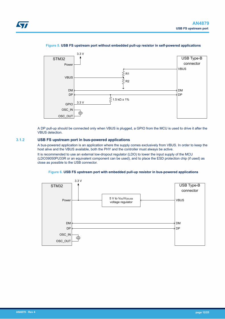
Figure 5. USB FS upstream port without embedded pull-up resistor in self-powered applications
STM32Power
VBUS
DMDP
OSC_IN
OSC_OUT
3.3 VUSB Type-B
connectorVBUS
DMDP
R1
R2
1.5 kΩ ± 1%GPIO 3.3 V
A DP pull-up should be connected only when VBUS is plugged, a GPIO from the MCU is used to drive it after theVBUS detection.
3.1.2 USB FS upstream port in bus-powered applicationsA bus-powered application is an application where the supply comes exclusively from VBUS. In order to keep thehost alive and the VBUS available, both the PHY and the controller must always be active.It is recommended to use an external low-dropout regulator (LDO) to lower the input supply of the MCU(LDO39050PU33R or an equivalent component can be used), and to place the ESD protection chip (if used) asclose as possible to the USB connector.
Figure 6. USB FS upstream port with embedded pull-up resistor in bus-powered applications
STM32
Power
DM
DP
OSC_IN
OSC_OUT
3.3 VUSB Type-B
connector
VBUS
DM
DP
5 V to VDD/VDDUSB
voltage regulator
AN4879USB FS upstream port
AN4879 - Rev 4 page 12/25
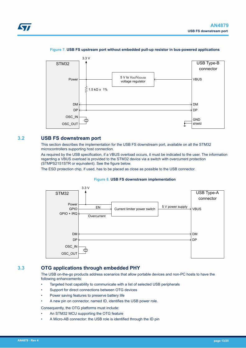
Figure 7. USB FS upstream port without embedded pull-up resistor in bus-powered applications
STM32
Power
DM
DP
OSC_IN
OSC_OUT
3.3 VUSB Type-B
connector
VBUS
DM
DP
GND shield
5 V to VDD/VDDUSB
voltage regulator
1.5 kΩ ± 1%
3.2 USB FS downstream portThis section describes the implementation for the USB FS downstream port, available on all the STM32microcontrollers supporting host connection.As required by the USB specification, if a VBUS overload occurs, it must be indicated to the user. The informationregarding a VBUS overload is provided to the STM32 device via a switch with overcurrent protection(STMPS2151STR or equivalent). See the figure below.The ESD protection chip, if used, has to be placed as close as possible to the USB connector.
Figure 8. USB FS downstream implementation
STM32
Power
DM
DP
OSC_IN
OSC_OUT
3.3 VUSB Type-A
connector
VBUS
DM
DP
Current limiter power switch5 V power supply
GPIOGPIO + IRQ
EN
Overcurrent
3.3 OTG applications through embedded PHYThe USB on-the-go products address scenarios that allow portable devices and non-PC hosts to have thefollowing enhancements:• Targeted host capability to communicate with a list of selected USB peripherals• Support for direct connections between OTG devices• Power saving features to preserve battery life• A new pin on connector, named ID, identifies the USB power role.
Consequently, the OTG platforms must include:• An STM32 MCU supporting the OTG feature• A Micro-AB connector: the USB role is identified through the ID pin
AN4879USB FS downstream port
AN4879 - Rev 4 page 13/25
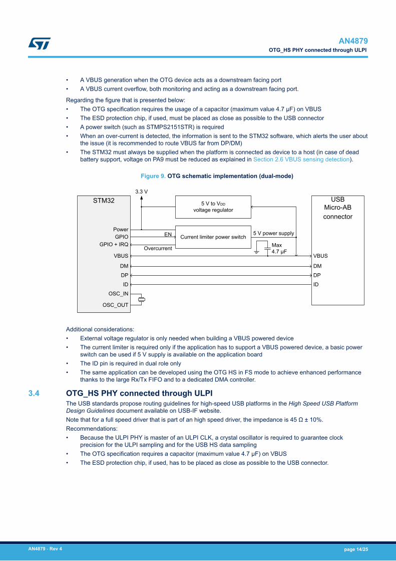
• A VBUS generation when the OTG device acts as a downstream facing port• A VBUS current overflow, both monitoring and acting as a downstream facing port.
Regarding the figure that is presented below:• The OTG specification requires the usage of a capacitor (maximum value 4.7 μF) on VBUS• The ESD protection chip, if used, must be placed as close as possible to the USB connector• A power switch (such as STMPS2151STR) is required• When an over-current is detected, the information is sent to the STM32 software, which alerts the user about
the issue (it is recommended to route VBUS far from DP/DM)• The STM32 must always be supplied when the platform is connected as device to a host (in case of dead
battery support, voltage on PA9 must be reduced as explained in Section 2.6 VBUS sensing detection).
Figure 9. OTG schematic implementation (dual-mode)
STM32
Power
DM
DP
OSC_IN
OSC_OUT
3.3 VUSB
Micro-AB connector
DM
DP
Current limiter power switch5 V power supply
GPIOGPIO + IRQ
EN
OvercurrentVBUS VBUS
ID ID
5 V to VDD
voltage regulator
Max4.7 µF
Additional considerations:• External voltage regulator is only needed when building a VBUS powered device• The current limiter is required only if the application has to support a VBUS powered device, a basic power
switch can be used if 5 V supply is available on the application board• The ID pin is required in dual role only• The same application can be developed using the OTG HS in FS mode to achieve enhanced performance
thanks to the large Rx/Tx FIFO and to a dedicated DMA controller.
3.4 OTG_HS PHY connected through ULPIThe USB standards propose routing guidelines for high-speed USB platforms in the High Speed USB PlatformDesign Guidelines document available on USB-IF website.Note that for a full speed driver that is part of an high speed driver, the impedance is 45 Ω ± 10%.Recommendations:• Because the ULPI PHY is master of an ULPI CLK, a crystal oscillator is required to guarantee clock
precision for the ULPI sampling and for the USB HS data sampling• The OTG specification requires a capacitor (maximum value 4.7 μF) on VBUS• The ESD protection chip, if used, has to be placed as close as possible to the USB connector.
AN4879OTG_HS PHY connected through ULPI
AN4879 - Rev 4 page 14/25
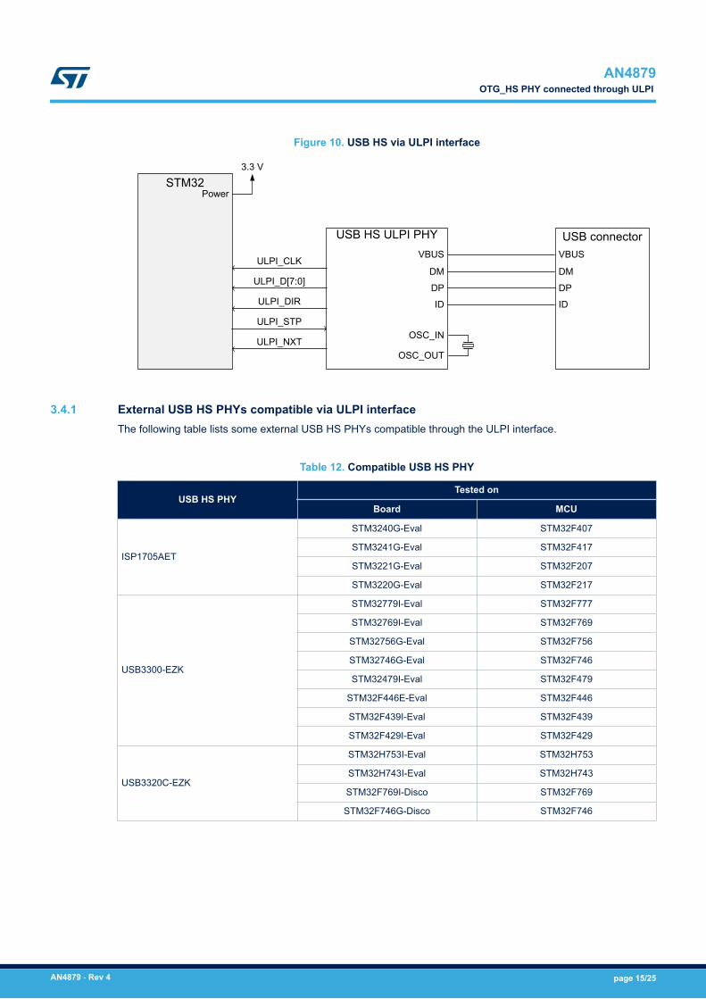
Figure 10. USB HS via ULPI interface
STM32Power
3.3 V
USB connector
DM
DP
VBUS
ID
USB HS ULPI PHYVBUS
DM
DP
ID
OSC_IN
OSC_OUT
ULPI_CLK
ULPI_D[7:0]
ULPI_DIR
ULPI_STP
ULPI_NXT
3.4.1 External USB HS PHYs compatible via ULPI interfaceThe following table lists some external USB HS PHYs compatible through the ULPI interface.
Table 12. Compatible USB HS PHY
USB HS PHYTested on
Board MCU
ISP1705AET
STM3240G-Eval STM32F407
STM3241G-Eval STM32F417
STM3221G-Eval STM32F207
STM3220G-Eval STM32F217
USB3300-EZK
STM32779I-Eval STM32F777
STM32769I-Eval STM32F769
STM32756G-Eval STM32F756
STM32746G-Eval STM32F746
STM32479I-Eval STM32F479
STM32F446E-Eval STM32F446
STM32F439I-Eval STM32F439
STM32F429I-Eval STM32F429
USB3320C-EZK
STM32H753I-Eval STM32H753
STM32H743I-Eval STM32H743
STM32F769I-Disco STM32F769
STM32F746G-Disco STM32F746
AN4879OTG_HS PHY connected through ULPI
AN4879 - Rev 4 page 15/25
3.5 USB applications through the embedded OTG HS PHYTo operate USB HS on STM32F7x3 devices there is no need to connect an external HS PHY via ULPI, as theyalready include an internal HS USB PHY.There are some other recommendations in addition to those detailed for the embedded USB FS PHY:• An external capacitor of 2.2 μF must be connected on the VDD12OTGHS pin• The HS PHY has an OTG_HS_REXT pin needed for calibration, this pin must be connected to GND via an
external precision resistor (3 KΩ ± 1%).
3.6 STM32 on USB-IF integrators listThe list of the STM32 devices with certified USB peripherals is available on www.usb.org. The table belowsummarizes the certified USB peripherals by STM32 device.
Table 13. Certified USB peripherals
STM32 device Certified category Speed(s) TID
STM32F072 Peripheral LS/FS 40001561
STM32F103 Peripheral LS/FS 40000455
STM32F105 Peripheral LS/FS 40001571
STM32F205/7 Peripheral LS/FS 40001366
STM32F205/7 Peripheral HS 40001365
STM32F207 Embedded host FS 120000252
STM32F207 Embedded host HS 120000251
STM32F303 Peripheral LS/FS 40001494
STM32F373 Peripheral LS/FS 40001496
STM32F405/7 Peripheral HS 40001393
STM32F405/7 Peripheral LS/FS 40001394
STM32F407 Embedded host HS 120000253
STM32F407 Embedded host FS 120000256
STM32F723 Peripheral HS 40001777
STM32F723 Embedded host FS 120000703
STM32F723 Embedded host HS 120000702
STM32F723 Peripheral LS/FS 40001776
STM32L053 Peripheral LS/FS 40001612
STM32L152 Peripheral LS/FS 10730015
STM32L476,
STM32L476ZGT6UPeripheral LS/FS 40001658
STM32L476,
STM32L476ZGT6UEmbedded host FS 120000348
AN4879USB applications through the embedded OTG HS PHY
AN4879 - Rev 4 page 16/25
4 FAQs (frequently asked questions)
Q: What is the minimum operating voltage for USB?A: The USB, including its internal transceiver, is functional only for VDD/VDDUSB ≥ 2.7 Volts. However, to becompliant with USB specification, a minimum of 3.0 V is needed. Below 2.7 Volts the functionality of the internaltransceiver is not ensured over the whole temperature range.
Q: The datasheet says that the USB transceiver functionality is ensured down to 2.7 V, but the full-speedelectrical characteristics are degraded in 2.7 to 3.0 V voltage range. What is the meaning of this sentence?A: When the USB operating voltage is below 3.0 V, ST guarantees that the PLL generates correctly the 48 MHzand that the analog transceivers are functional: the USB is correctly operating.However, the electrical signals will not be compliant with the USB2.0 Full speed specification, and, consequently,some tests needed to get the USB certification (such as the eye diagram test) will not pass. In other words, theUSB is operational, but the customer cannot get the USB certification.Refer to www.usb.org for more details about the electrical requirements needed to be compliant with the USBspecification.
Q: The pull up resistor on D+ line should be always added for the STM32 acting as a full speed device?A: A full speed device uses a pull up resistor attached to D+ to specify itself as a full speed device (and to indicateits speed). The pull up resistor at the device end will also be used by the host or hub to detect the presence of adevice connected to its port. Without a pull up resistor, USB assumes there is nothing connected to the bus.On some STM32 microcontrollers the pull up resistor is already embedded. Otherwise, the customer needs to addit. Refer to Embedded pull-up resistor on USB_DP line in Table 3. USB implementation in STM32 devices to knowif this resistor is integrated on the STM32 MCU you are using.
Q: In order to manage the VBUS sensing for USB device, are there any recommendations for the resistor bridgevalues?A: Resistor bridge values should be chosen with respect to the following conditions:• Voltage should be lower than 4 V• Voltage should be higher than 0.7×VDD• A 200 μA typical current consumption is tolerated.
User may refer to "Management of VBUS sensing for USB device design" shared on ST communityhttp://community.st.com
Q: Can the external clock source (HSE bypass mode) be used for the USB clock source?A: Yes, this is possible. HSE ON with an external crystal or HSE in bypass mode are required, but HSI cannot beused.
Q: Can we use two USB ports simultaneously (when they are available)?A: Yes, this is feasible.
Q: It is possible to connect more than one device to the same USB port configured as host?A: No, hub operation is not supported.
Q: Can the STM32 USB FS peripheral be used to make a USB LS device?A: No, only Full-speed transfers are supported in device mode. Refer to Section 2.2 Supported USB speeds formore details.
Q: According to the USB specification (FS driver characteristics), when the full-speed driver is / is not part of ahigh-speed capable transceiver, the impedance of each of the drivers must be in the range 40.5 to 49.5 Ω / 28 to44 Ω, respectively. Are the STM32 devices embedding those matching resistors?A: Yes. On the internal USB PHYs, the matching output impedance is already embedded in the pad transceiverand is in line with the USB specification. No external resistors are needed.
Q: Is it possible to use the USB peripheral when the operating voltage VDD on the MCU is below 2.7 V?
AN4879FAQs (frequently asked questions)
AN4879 - Rev 4 page 17/25
A: This is possible only if a VDDUSB pin is available to power the USB block. In this case, the microcontroller canbe powered with the minimum specified supply voltage, while an independent 3.3 V power supply can beconnected to VDDUSB.
AN4879FAQs (frequently asked questions)
AN4879 - Rev 4 page 18/25
5 References
• System Level ESD-expanded, JEDEC, September 2013.• Improve System ESD Protection While Lowering On-Chip ESD Protection, www.mobiledevdesign.com,
February 2009.• USB 2.0 specification, revision 2.0, April 2000, available at www.usb.org.• On The Go and Embedded Host Supplement to the USB revision 2.0 specification, revision 2.0, July 2012
available at www.usb.org.• High Speed USB Platform Design Guidelines, available at www.usb.org.
AN4879References
AN4879 - Rev 4 page 19/25
6 Conclusion
This application note was developed in order to help STM32MCUs users to correctly design their USBapplications.All aspects described inside this document, and specifically requirements described in Section 3 Hardwareguidelines for USB implementation , are mandatory for correct operation of the USB peripheral on STM32 MCUs,and for ensuring its electrical compliance with the USB standard.
AN4879Conclusion
AN4879 - Rev 4 page 20/25
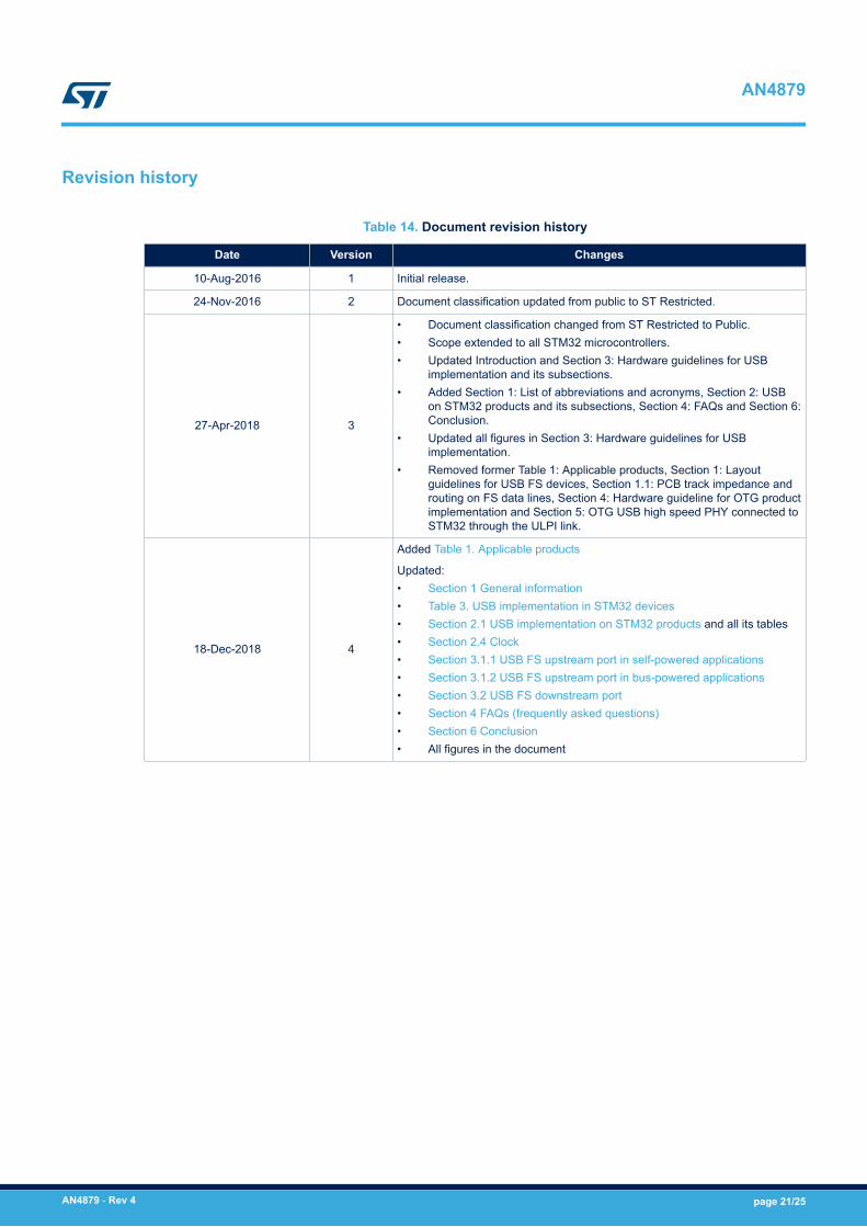
Revision history
Table 14. Document revision history
Date Version Changes
10-Aug-2016 1 Initial release.
24-Nov-2016 2 Document classification updated from public to ST Restricted.
27-Apr-2018 3
• Document classification changed from ST Restricted to Public.• Scope extended to all STM32 microcontrollers.• Updated Introduction and Section 3: Hardware guidelines for USB
implementation and its subsections.• Added Section 1: List of abbreviations and acronyms, Section 2: USB
on STM32 products and its subsections, Section 4: FAQs and Section 6:Conclusion.
• Updated all figures in Section 3: Hardware guidelines for USBimplementation.
• Removed former Table 1: Applicable products, Section 1: Layoutguidelines for USB FS devices, Section 1.1: PCB track impedance androuting on FS data lines, Section 4: Hardware guideline for OTG productimplementation and Section 5: OTG USB high speed PHY connected toSTM32 through the ULPI link.
18-Dec-2018 4
Added Table 1. Applicable products
Updated:• Section 1 General information• Table 3. USB implementation in STM32 devices• Section 2.1 USB implementation on STM32 products and all its tables• Section 2.4 Clock• Section 3.1.1 USB FS upstream port in self-powered applications• Section 3.1.2 USB FS upstream port in bus-powered applications• Section 3.2 USB FS downstream port• Section 4 FAQs (frequently asked questions)• Section 6 Conclusion• All figures in the document
AN4879
AN4879 - Rev 4 page 21/25
Contents
1 General information . . . . . . . . . . . . . . . . . . . . . . . . . . . . . . . . . . . . . . . . . . . . . . . . . . . . . . . . . . . . . . .2
2 USB on STM32 products . . . . . . . . . . . . . . . . . . . . . . . . . . . . . . . . . . . . . . . . . . . . . . . . . . . . . . . . . . .3
2.1 USB implementation on STM32 products . . . . . . . . . . . . . . . . . . . . . . . . . . . . . . . . . . . . . . . . . . 4
2.2 Supported USB speeds . . . . . . . . . . . . . . . . . . . . . . . . . . . . . . . . . . . . . . . . . . . . . . . . . . . . . . . . . 6
2.3 Protection against ESD and EMI. . . . . . . . . . . . . . . . . . . . . . . . . . . . . . . . . . . . . . . . . . . . . . . . . . 7
2.4 Clock. . . . . . . . . . . . . . . . . . . . . . . . . . . . . . . . . . . . . . . . . . . . . . . . . . . . . . . . . . . . . . . . . . . . . . . . . 9
2.5 Power . . . . . . . . . . . . . . . . . . . . . . . . . . . . . . . . . . . . . . . . . . . . . . . . . . . . . . . . . . . . . . . . . . . . . . . . 9
2.6 VBUS sensing detection. . . . . . . . . . . . . . . . . . . . . . . . . . . . . . . . . . . . . . . . . . . . . . . . . . . . . . . . 10
3 Hardware guidelines for USB implementation . . . . . . . . . . . . . . . . . . . . . . . . . . . . . . . . . . . . .11
3.1 USB FS upstream port . . . . . . . . . . . . . . . . . . . . . . . . . . . . . . . . . . . . . . . . . . . . . . . . . . . . . . . . . 11
3.1.1 USB FS upstream port in self-powered applications . . . . . . . . . . . . . . . . . . . . . . . . . . . . . 11
3.1.2 USB FS upstream port in bus-powered applications . . . . . . . . . . . . . . . . . . . . . . . . . . . . . 12
3.2 USB FS downstream port. . . . . . . . . . . . . . . . . . . . . . . . . . . . . . . . . . . . . . . . . . . . . . . . . . . . . . . 13
3.3 OTG applications through embedded PHY . . . . . . . . . . . . . . . . . . . . . . . . . . . . . . . . . . . . . . . . 13
3.4 OTG_HS PHY connected through ULPI. . . . . . . . . . . . . . . . . . . . . . . . . . . . . . . . . . . . . . . . . . . 14
3.4.1 External USB HS PHYs compatible via ULPI interface . . . . . . . . . . . . . . . . . . . . . . . . . . . 15
3.5 USB applications through the embedded OTG HS PHY . . . . . . . . . . . . . . . . . . . . . . . . . . . . . 16
3.6 STM32 on USB-IF integrators list . . . . . . . . . . . . . . . . . . . . . . . . . . . . . . . . . . . . . . . . . . . . . . . . 16
4 FAQs (frequently asked questions). . . . . . . . . . . . . . . . . . . . . . . . . . . . . . . . . . . . . . . . . . . . . . . .17
5 References . . . . . . . . . . . . . . . . . . . . . . . . . . . . . . . . . . . . . . . . . . . . . . . . . . . . . . . . . . . . . . . . . . . . . . .19
6 Conclusion . . . . . . . . . . . . . . . . . . . . . . . . . . . . . . . . . . . . . . . . . . . . . . . . . . . . . . . . . . . . . . . . . . . . . . .20
Revision history . . . . . . . . . . . . . . . . . . . . . . . . . . . . . . . . . . . . . . . . . . . . . . . . . . . . . . . . . . . . . . . . . . . . . . .21
Contents . . . . . . . . . . . . . . . . . . . . . . . . . . . . . . . . . . . . . . . . . . . . . . . . . . . . . . . . . . . . . . . . . . . . . . . . . . . . . .22
List of tables . . . . . . . . . . . . . . . . . . . . . . . . . . . . . . . . . . . . . . . . . . . . . . . . . . . . . . . . . . . . . . . . . . . . . . . . . .23
List of figures. . . . . . . . . . . . . . . . . . . . . . . . . . . . . . . . . . . . . . . . . . . . . . . . . . . . . . . . . . . . . . . . . . . . . . . . . .24
AN4879Contents
AN4879 - Rev 4 page 22/25
List of tablesTable 1. Applicable products . . . . . . . . . . . . . . . . . . . . . . . . . . . . . . . . . . . . . . . . . . . . . . . . . . . . . . . . . . . . . . . . . . 1Table 2. List of abbreviations and acronyms . . . . . . . . . . . . . . . . . . . . . . . . . . . . . . . . . . . . . . . . . . . . . . . . . . . . . . . 2Table 3. USB implementation in STM32 devices . . . . . . . . . . . . . . . . . . . . . . . . . . . . . . . . . . . . . . . . . . . . . . . . . . . . 3Table 4. USB implementation on STM32 mainstream products. . . . . . . . . . . . . . . . . . . . . . . . . . . . . . . . . . . . . . . . . . . 4Table 5. USB implementation on STM32 high-performance products . . . . . . . . . . . . . . . . . . . . . . . . . . . . . . . . . . . . . . 5Table 6. USB implementation on STM32 ultra-low-power products . . . . . . . . . . . . . . . . . . . . . . . . . . . . . . . . . . . . . . . . 6Table 7. Supported OTG_FS speeds . . . . . . . . . . . . . . . . . . . . . . . . . . . . . . . . . . . . . . . . . . . . . . . . . . . . . . . . . . . . 6Table 8. Supported OTG_FS speeds . . . . . . . . . . . . . . . . . . . . . . . . . . . . . . . . . . . . . . . . . . . . . . . . . . . . . . . . . . . . 6Table 9. JESD22-A114D standard class levels . . . . . . . . . . . . . . . . . . . . . . . . . . . . . . . . . . . . . . . . . . . . . . . . . . . . . . 7Table 10. IEC 61000-4-2 standard class levels . . . . . . . . . . . . . . . . . . . . . . . . . . . . . . . . . . . . . . . . . . . . . . . . . . . . . . 8Table 11. ESD protection . . . . . . . . . . . . . . . . . . . . . . . . . . . . . . . . . . . . . . . . . . . . . . . . . . . . . . . . . . . . . . . . . . . . . 8Table 12. Compatible USB HS PHY . . . . . . . . . . . . . . . . . . . . . . . . . . . . . . . . . . . . . . . . . . . . . . . . . . . . . . . . . . . . . 15Table 13. Certified USB peripherals . . . . . . . . . . . . . . . . . . . . . . . . . . . . . . . . . . . . . . . . . . . . . . . . . . . . . . . . . . . . . 16Table 14. Document revision history . . . . . . . . . . . . . . . . . . . . . . . . . . . . . . . . . . . . . . . . . . . . . . . . . . . . . . . . . . . . . 21
AN4879List of tables
AN4879 - Rev 4 page 23/25
List of figuresFigure 1. JESD22-A114D standard test waveform . . . . . . . . . . . . . . . . . . . . . . . . . . . . . . . . . . . . . . . . . . . . . . . . . . 7Figure 2. IEC 61000-4-2 standard waveform . . . . . . . . . . . . . . . . . . . . . . . . . . . . . . . . . . . . . . . . . . . . . . . . . . . . . . 8Figure 3. HS PHY PLLs on STM32F7x3 devices . . . . . . . . . . . . . . . . . . . . . . . . . . . . . . . . . . . . . . . . . . . . . . . . . . . 9Figure 4. USB FS upstream port with embedded pull-up resistor in self-powered applications . . . . . . . . . . . . . . . . . . . 11Figure 5. USB FS upstream port without embedded pull-up resistor in self-powered applications . . . . . . . . . . . . . . . . . 12Figure 6. USB FS upstream port with embedded pull-up resistor in bus-powered applications . . . . . . . . . . . . . . . . . . . 12Figure 7. USB FS upstream port without embedded pull-up resistor in bus-powered applications . . . . . . . . . . . . . . . . . 13Figure 8. USB FS downstream implementation . . . . . . . . . . . . . . . . . . . . . . . . . . . . . . . . . . . . . . . . . . . . . . . . . . . 13Figure 9. OTG schematic implementation (dual-mode) . . . . . . . . . . . . . . . . . . . . . . . . . . . . . . . . . . . . . . . . . . . . . . 14Figure 10. USB HS via ULPI interface. . . . . . . . . . . . . . . . . . . . . . . . . . . . . . . . . . . . . . . . . . . . . . . . . . . . . . . . . . . 15
AN4879List of figures
AN4879 - Rev 4 page 24/25
IMPORTANT NOTICE – PLEASE READ CAREFULLY
STMicroelectronics NV and its subsidiaries (“ST”) reserve the right to make changes, corrections, enhancements, modifications, and improvements to STproducts and/or to this document at any time without notice. Purchasers should obtain the latest relevant information on ST products before placing orders. STproducts are sold pursuant to ST’s terms and conditions of sale in place at the time of order acknowledgement.
Purchasers are solely responsible for the choice, selection, and use of ST products and ST assumes no liability for application assistance or the design ofPurchasers’ products.
No license, express or implied, to any intellectual property right is granted by ST herein.
Resale of ST products with provisions different from the information set forth herein shall void any warranty granted by ST for such product.
ST and the ST logo are trademarks of ST. All other product or service names are the property of their respective owners.
Information in this document supersedes and replaces information previously supplied in any prior versions of this document.
© 2018 STMicroelectronics – All rights reserved
AN4879
AN4879 - Rev 4 page 25/25