u.s. practices for concrete containment design and evaluation
DESCRIPTION
Centrales nuclearesTRANSCRIPT

U.S. Practices for
Concrete Containment
Design and Evaluation
Presented by
Jorma Arros, PhD
Senior Manager
Advanced Engineering Analysis
Stockholm
2015-01-28

2 2
Presentation Outline
• U.S. Nuclear Power Trivia
– Power generation statistics
– New plants
• U.S. Concrete Containment Design Codes
• Load Characterization
– Design basis loads
– Beyond design basis loads
• Beyond Design Basis Event (BDBE) Modeling/Analysis Examples
– ANSYS
– LS-DYNA

3 3
U.S. Nuclear Power Trivia – Generation Statistics

4 4
U.S. Nuclear Power Trivia – Planned New Plants

5 5
U.S. Nuclear Power Trivia – Planned New Plants, cont’d

6 6
Design Codes
• The main design code for concrete containment design in the U.S. is ASME Section III, Division 2, Code for Concrete Containments, 2007 Edition – formerly also known as ACI-359
• Key concepts in this code: – Service loads vs factored loads (severe environmental, extreme environmental, abnormal
loads)
– Primary force and secondary force
– Essentially an allowable stress approach
– Allowable stress: • Detailed elaborate allowables for factored loads
• Simpler straightforward allowables for service loads
• Supporting codes include: – ASCE 4-98 (4-09) and ASCE 43-05 for seismic design
– NEI 07-13, Revision 8 for aircraft impact
– ASME/ANS RA-S-2009 for external events PRA

7 7
Load Charaterization
• Design basis events are defined as conditions of normal operation, including anticipated operational occurrences, design basis accidents, external events, and natural phenomena for which the plant must be designed to ensure the following functions:
– (1) The integrity of the reactor coolant pressure boundary
– (2) The capability to shut down the reactor and maintain it in a safe shutdown condition; or
– (3) The capability to prevent or mitigate the consequences of accidents which could result in potential offsite exposures comparable to the applicable guideline exposures set forth in § 50.34(a)(1) or § 100.11 of this chapter, as applicable.
• Beyond design basis accidents refer to accident sequences that are possible but were not fully considered in the design process because they were judged to be too unlikely. (In that sense, they are considered beyond the scope of design basis accidents that a nuclear facility must be designed and built to withstand.) As the regulatory process strives to be as thorough as possible, "beyond design-basis" accident sequences are analyzed to fully understand the capability of a design. [ from http://www.nrc.gov/reading-rm/basic-ref/glossary/beyond-design-basis-accidents.html ]

8 8
On Evaluation of BDBEs
• Severe accidents should be evaluated to identify reasonable measures for prevention or mitigation, based on realistic or best-estimate assumptions, methods, and analytical criteria regarding specific severe accidents.
• Chapter 19 of Regulatory Guide 1.206, Combined License Applications for Nuclear Power Plants, requires licensees of future nuclear power reactors to perform a probabilistic risk assessment that includes analysis of BDBEs – Also addressed in Section 19 of the Standard Review Plan, NUREG-800,
Probabilistic Risk Assessment and Severe Accident Evaluation for New Reactors
• BDBEs most often evaluated as a PRA – acceptance criteria is “true best estimate failure”

9 9
BDBE Example – Containment Overpressure
• Containment Pressure exceeding design as a result of beyond design
basis event – prestressed containment
• Ultimate pressure capacity, for varying thermal conditions, evaluated
in support of Level 2 internal events PRA
• Nonlinear FE analysis – both material and geometric nonlinearity
• Global nonlinear response analysis with ANSYS Wedge Model –
Solid65 elements for concrete with smeared rebar
• Local analysis of Equipment hatch, personnel access airlock, piping
and electrical penetrations, etc. with nonlinear local ANSYS models
• Liner analysis with a hand calculation methods

10 10
BDBE Example – Containment Overpressure
Section of a large dry PWR containment structure designed to about 60 psi
design basis accident pressure per the applicable the code requirements

11 11
Wedge model for Global Response Analysis
Nonlinear ANSYS wedge model – SOLID65 concrete elements – smeared rebar

12 12
Wedge model for Global Response Analysis
Radial wall displacement (inches) at initial condition – dead weight + post-tension

13 13
Wedge model for Global Response Analysis
Radial wall displacement at cylinder mid-height vs pressure
• Liner tearing at 175 psi

14 14
Local 3D Nonlinear Analysis of Equipment Hatch Cover
Equipment hatch displacement contour during snap-through buckling at a pressure of 0.215*800=172 psi, significantly lower than the peak of 620 psi.

15 15
BDBE Example – Aircraft Impact
• Aircraft impact analysis with LS-DYNA
• Both missile/target interaction method and the Riera force history
method
• Nuclear Island modeled in “full detail”
• Winfrith material model with both discrete beam and smeared rebar
– Typically eight to twelve elements through the thickness in the impacted area
and vicinity
– Areas removed from the impact area modeled with linear shell elements

16 16
Beyond Design Basis Aircraft Impact
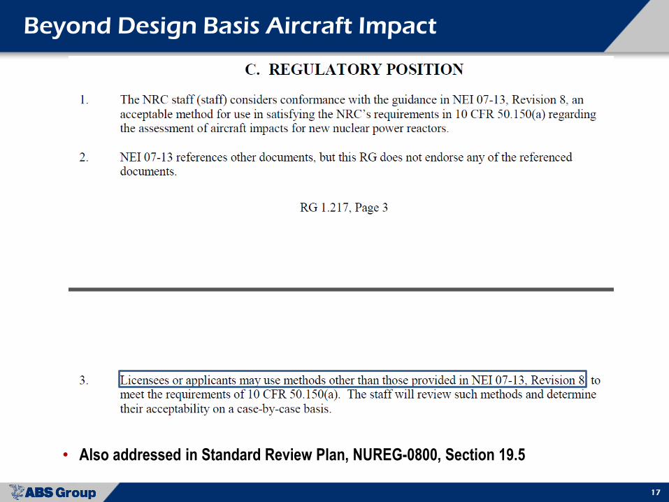
17 17
Beyond Design Basis Aircraft Impact
• Also addressed in Standard Review Plan, NUREG-0800, Section 19.5

18 18
Beyond Design Basis Aircraft Impact – Modeling Verification
• LS-DYNA FE modeling and Winfrith concrete material model
verification utilizing VTT IMPACT test results - by comparing LS-DYNA
results vs those observed in the IMPACT laboratory tests

19 19
VTT Impact Tests Utilized for Material Model Verification
• LS-DYNA model of the VTT IMPACT test set-up – hard punching missile

20 20
VTT Impact Tests Utilized for Material Model Verification
• Hard missile punch through of the reinforced concrete target plate

21 21
VTT Impact Tests Utilized for Material Model Verification
• Deceleration of the missile during punch through

22 22
Discrete rebar and Steel Member modeling in a Fictitious
Nuclear Building Impact Area – used for LS-DYNA FEA tests
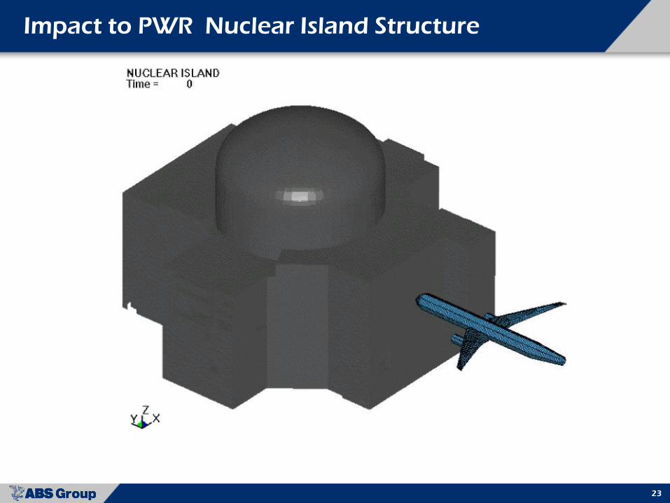
23 23
Impact to PWR Nuclear Island Structure

24 24
Impact to PWR Nuclear Island Structure
25 25
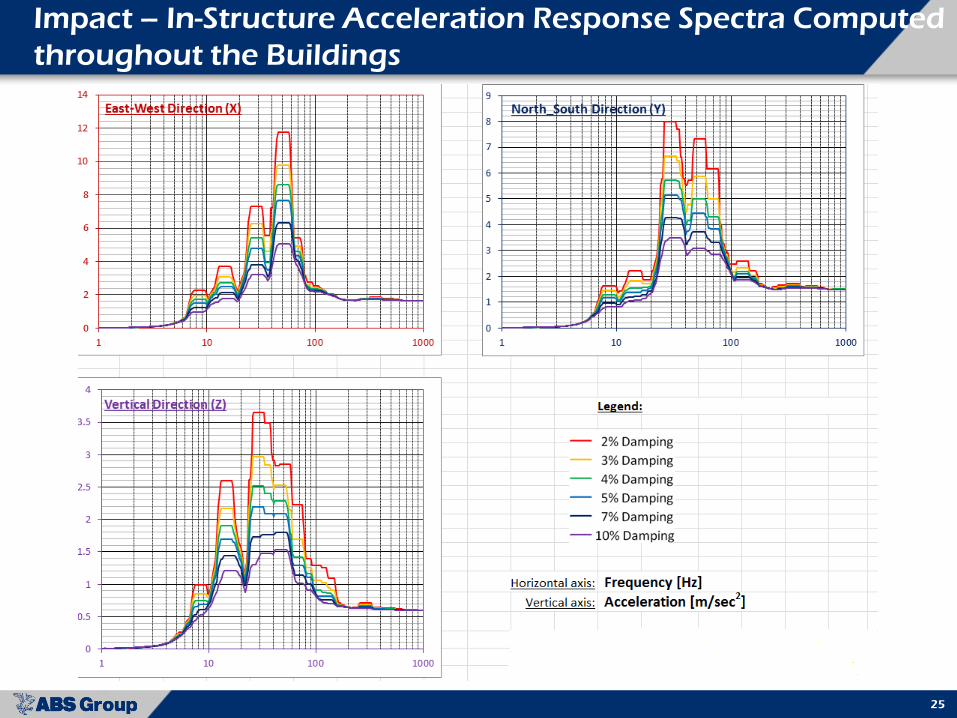
Impact – In-Structure Acceleration Response Spectra Computed
throughout the Buildings

26 26
BWR Containment Model for Design Basis Earthquake,
Wetwell Oscillations, and Steam Line Break Analyses

27 27
BWR Containment Model for Design Basis Earthquake,
Wetwell Oscillations, and Steam Line Break Analyses
Major piping and supports included in detailed modeling