us integrated battery systems, llcusintegratedbatterysystems.com/esw/files/ems_modbus_spec.pdfthe...
TRANSCRIPT

Energy Management System
MODBUS Interface Speci�cations
Hardware (physical layer) This implementation will use serial RS-232 or RS-485 communication standards. The interface standard is selectable with a parameter in the configuration file, and the default format is RS232. Data will be transmitted at settable baud rate ( see below), 8 bits, 1 stop bit, no parity. When the CPU is powered down, the transmitter will be in the high impedance state. An input for logic signal detection will also be provided to detect an open or closed circuit.
Picture 1: MODBUS Interface (default RS232)
US Integrated Battery Systems, LLC
Engineering A Cleaner & Greener World© CopyRight US Integrated Battery Systems 2013

The connector on the interface will be a 5 pin Molex p/n 0705550004. The pin functions are as follows: In RS485 Mode: 1: Data +; 2: Data -; 3: Ground (GND); 4: Relay; 5: Relay In RS-232 Mode: 1: Transmit Data (TXD); 2: Receive Data (RXD); 3: Ground (GND); 4: Relay; 5: Relay Pins 1-3 are output pins for MODBUS communication. Pins 4-5 are input pins for logical signal detection of an open or closed circuit.
MODBUS Data Format The data format is from the MODBUS APPLICATION PROTOCOL SPECIFICATION V1.1b http://www. modbus.org/docs/Modbus_Application_Protocol_V1_1 b.pdf The CPU will respond to one command: command 04 read input registers. The following will be sent: Command 1 byte (always $04) Starting address 2 bytes Quantity of input registers 2 bytes CRC 2 bytes The register address defines what type of data will be transmitted. Up to 256 cells will be supported in the following ranges: 0000-00FF Pack information and alerts 0100-01FF Cell Voltages (in millivolts) 0200-02FF Cell Temperatures (in degrees F, 2s complement encoded) The voltage and temperature for the actual number of cells detected will be transmitted, with a maximum of up to 256 cells. The quantity of input registers can only be a maximum of 124 in one command. To send more, send a second command. The values can range for 0x0000 to 0x007D. Registers outside the range of actual cells in a request will return 0x0000. Response to Command: Function code 1 byte Always 04
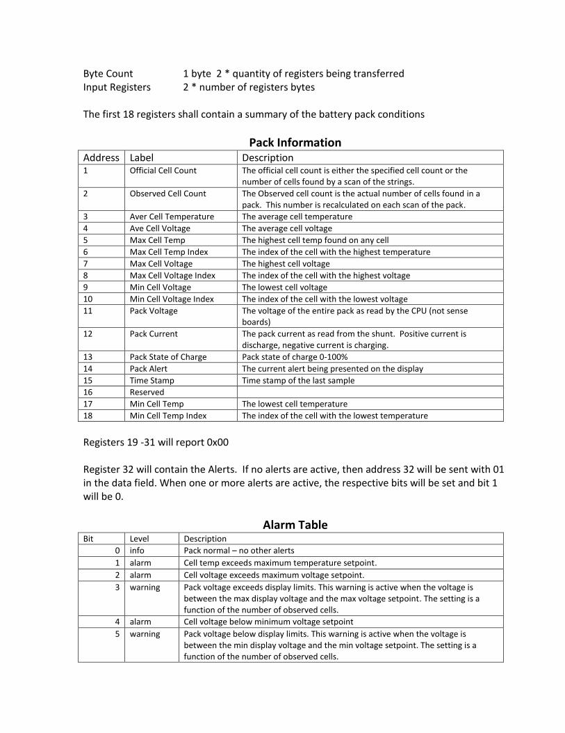
Byte Count 1 byte 2 * quantity of registers being transferred Input Registers 2 * number of registers bytes The first 18 registers shall contain a summary of the battery pack conditions
Pack Information Address Label Description 1 Official Cell Count The official cell count is either the specified cell count or the
number of cells found by a scan of the strings.
2 Observed Cell Count The Observed cell count is the actual number of cells found in a pack. This number is recalculated on each scan of the pack.
3 Aver Cell Temperature The average cell temperature
4 Ave Cell Voltage The average cell voltage
5 Max Cell Temp The highest cell temp found on any cell
6 Max Cell Temp Index The index of the cell with the highest temperature
7 Max Cell Voltage The highest cell voltage
8 Max Cell Voltage Index The index of the cell with the highest voltage
9 Min Cell Voltage The lowest cell voltage
10 Min Cell Voltage Index The index of the cell with the lowest voltage
11 Pack Voltage The voltage of the entire pack as read by the CPU (not sense boards)
12 Pack Current The pack current as read from the shunt. Positive current is discharge, negative current is charging.
13 Pack State of Charge Pack state of charge 0-100%
14 Pack Alert The current alert being presented on the display
15 Time Stamp Time stamp of the last sample
16 Reserved
17 Min Cell Temp The lowest cell temperature
18 Min Cell Temp Index The index of the cell with the lowest temperature
Registers 19 -31 will report 0x00 Register 32 will contain the Alerts. If no alerts are active, then address 32 will be sent with 01 in the data field. When one or more alerts are active, the respective bits will be set and bit 1 will be 0.
Alarm Table Bit Level Description
0 info Pack normal – no other alerts
1 alarm Cell temp exceeds maximum temperature setpoint.
2 alarm Cell voltage exceeds maximum voltage setpoint.
3 warning Pack voltage exceeds display limits. This warning is active when the voltage is between the max display voltage and the max voltage setpoint. The setting is a function of the number of observed cells.
4 alarm Cell voltage below minimum voltage setpoint
5 warning Pack voltage below display limits. This warning is active when the voltage is between the min display voltage and the min voltage setpoint. The setting is a function of the number of observed cells.

6 alarm Pack current above maximum current setpoint
7 warning Pack current is above display scale and below max current setpoint
8 fault Pack to chassis connection detected
9 fault Sense board communication error. The number of sense boards detected does not agree with the official cell count.
10 fault Undefined system error
11 alarm Cell temperature below minimum temperature setpoint
12 (future) (future)
13 warning Logic state of open or closed circuit
Configuration Options: The configuration file (part of the software stored in EEPROM- not user programmable) will contain the 3 parameters as follows: 1. Baud rate sets the serial transmission speed 1200 to 115200 2. Comm mode selects RS-232 or RS-485 3. MODBUS Slave Address which defaults to 1