us army corps of engineers new england district 696 …€¦ · · 2014-09-09regulatory division...
TRANSCRIPT

Regulatory Division CENAE-R Permit Number: NAE-2009-789
Aileen Kenney Director of Permitting
DEPARTMENT OF THE ARMY US ARMY CORPS OF ENGINEERS
NEW ENGLAND DISTRICT 696 VIRGINIA ROAD
CONCORD MA 01742-2751
September 4, 2014
Deepwater Wind Block Island, LLC 56 Exchange Terrace Street Providence, Rhode Island 02903-1772
Dear Ms. Ketmey:
Attached are two copies of a Department of the Army permit authorizing your Block Island Wind Farm project. Please sign both copies of the permit and return one signed copy to this office at the address above. A fee of $100.00 is required. Please enclose a check made payable to "F AO New England District", and return it with the signed permit copy. Please ensure your address and social security number, or tax identification number for businesses, are on the check. The authorized work cannot start until we receive a complete, signed copy of the permit.
You are required to complete and return the attached forms to this office: 1. Work Start Notification Form at least two weeks before the anticipated work start date. 2. Compliance Certification Form within one month following the completion of the
authorized work.
This permit is a limited authorization containing a specific set of conditions. Please read the permit thoroughly to familiarize yourself with those conditions, including any conditions contained on the attached state water quality certification. If a contractor does the work for you, both you and the contractor are responsible for ensuring that the work is done in compliance with the permit's terms and conditions, as any violations could result in civil or criminal penalties.
The Corps of Engineers has consulted with the National Marine Fisheries Service (NMFS) regarding the effects of your project on Essential Fish Habitat (EFH) designated under the Magnuson-Stevens Fishery Conservation and Management Act. To minimize impacts to the aquatic environment, conservation recommendations from several agencies are included as special conditions attached to this permit.
This letter contains an approved jurisdictional determination for your subject site and a proffered permit for your proposed project. If you object to either this determination or decision, you may request an administrative appeal under Corps regulations at 33 CPR 331. A combined Notification of Administrative Appeal Options and Process (NAP) and Request for Appeal (RF A) form, and flow chart explaining the appeals process and your options, are attached to this

-2-
letter. If you desire to appeal this determination, you must submit a completed RF A form along with any suppmiing or clarifying information to Michael G. Vissichelli; Administrative Appeals Review Officer; North Atlantic Division, Corps of Engineers; North Atlantic Fort Hamilton Military Community, Bldg. 301; General Lee Avenue; Brooklyn, NY 11252-6700. Contact info: (347) 370-4663 or [email protected].
In order for an RF A to be accepted by the Corps, the Corps must determine that it is complete, that it meets the criteria for appeal under 33 CFR 331.5, and that it has been received by the Division Office within 60 days of the date of the NAP.
You may not appeal conditions contained in the State water quality certification or the CZM consistency determination under this program as they are automatically included in the Federal permit. Also note that the Department of the Army permit process does not supersede any other agency's jurisdiction.
We continually strive to improve our customer service. In order for us to better serve you, we would appreciate your completing our Customer Service Survey located at http:/ I corpsmapu. usace. armv .mil/ em apex/f?p=regulatory survey.
If you have any questions regarding this correspondence, please contact Michael Elliott at (978) 318-8131, (800) 343-4789, or use (800) 363-4367 within Massachusetts.
Enclosures
Copy Furnished:
Jennifer Daniels Director of Offshore Energy Tetra Tech 160 Federal Street, 3rd Floor Boston, MA 02110
Since ly, r-; /
,-~,/&~--\, ' obert J. DeSista -
Acting Chief, Regulatory Division

Applicant Options with Initial/Proffered Permit
Applicant/Corps sign standard permit or applicant accepts
letter of permission.
Initial proffered permit sent to
applicant.
The project is authorized. Yes
Applicant/Corps sign standard permit or applicant accepts
letter of permission.
No
Applicant sends specific objections to district engineer. The district engineer
will either modify the permit to remove all objectionable conditions, remove some
of the objectionable conditions, or not modify the permit. A proffered permit is sent to the
applicant for reconsideration with the combined "NAP and RFA" form.
The project is authorized. Yes
Appendix 8
Applicant declines the proffered permit. The declined individual permit may be appealed by submitting an RFA to the division engineer within 60 days of the
date of the NAP.

A: INITIAL PROFFERED PERMIT: You may accept or object to the permit.
• ACCEPT: If you received a Standard Permit, you may sign the permit document and return it to the New England District Engineer for final authorization. If you received a Letter of Permission (LOP), you may accept the LOP and your work is authorized. Your signature on the Standard Permit or acceptance of the LOP means that you accept the permit in its entirety, and waive all rights to appeal the permit, including its terms and conditions, and approved jurisdictional determinations (JD) associated with the permit.
• OBJECT: If you object to the permit (Standard or LOP) because of certain terms and conditions therein, you may request that the permit be modified accordingly. You must complete Section II of this form and return the form to the New England District Engineer. Your objections must be received by the New England District Engineer within 60 days of the date of this notice, or you will forfeit your right to appeal the permit in the future. Upon receipt of your letter, the New England District Engineer will evaluate your objections and may: (a) modify the permit to address all of your concerns, (b) modify the pennit to address some of your objections, or (c) not modify the permit having determined that the permit should be issued as previously written. After evaluating your objections, the New England Distri~t Engineer will send you a proffered permit for your reconsideration, as indicated in Section B below.
B: PROFFERED PERMIT: You may accept or appeal the permit
• ACCEPT: If you received a Standard Permit, you may sign the permit document and return it to the New England District Engineer for final authorization. If you received a Letter of Permission (LOP), you may accept the LOP and your work is authorized. Your signature on the Standard Permit or acceptance of the LOP means that you accept the permit in its entirety, and waive all rights to appeal the permit, including its terms and conditions, and approved jurisdictional determinations associated with the permit.
• APPEAL: If you choose to decline the proffered permit (Standard or LOP) because of certain terms and conditions therein, you may appeal the declined permit under the Corps of Engineers Administrative Appeal Process by completing Section II of this form and sending the form to the North Atlantic Division Engineer, ATTN: CENAD-PD-PSD-0, Fort Hamilton Military Community, Building 30 I, General Lee A venue, Brooklyn, NY 11252-6700. This form must be received by the North Atlantic Division Engineer within 60 days of the date of this notice with a copy furnished to the New England District Engineer.
C: PERMIT DENIAL: You may appeal the denial of a pe1mit under the Corps of Engineers Administrative Appeal Process by completing Section II of this form and sending the form to the Nm1h Atlantic Division Engineer, ATTN: CENAD-PD-PSD-0; Fort Hamilton Military Community, Building 301, General Lee Avenue, Brooklyn, NY 11252-6700. This form must be received by the Nm1h Atlantic Division Engineer within 60 days of the date of this notice with a copy furnished to the New England District Engineer.
D: APPROVED JURISDICTIONAL DETERMINATION: You may accept or appeal the approved JD or provide new information. • ACCEPT: You do not need to notify the Corps to accept an approved JD. Failure to notify the Corps within 60 days of the date
of this notice, means that you accept the approved JD in its entirety, and waive all rights to appeal the approved JD.
• APPEAL: If you disagree with the approved JD, you may appeal the approved JD under the Corps of Engineers Administrative Appeal Process by completing Section II ofthis form and sending the form to the Nm1h Atlantic Division Engineer, ATTN: CENAD-PD-PSD-0, Fort Hamilton Military Community, Building 301, General Lee Avenue, Brooklyn, NY 11252-6700. This form must be received by the North Atlantic Division Engineer within 60 days of the date of this notice with a copy furnished to the New England District Engineer.

E: PRELIMINARY JURISDICTIONAL DETERMINATION: You do not need to respond to the Corps regarding the preliminary JD. The Preliminary JD is not appealable. If you wish, you may request an approved JD (which may be appealed), by contacting the Corps district for fmther instruction. Also you may provide new information for further consideration by the Corps to reevaluate the JD.
REASONS FOR APPEAL OR OBJECTIONS: (Describe your reasons for appealing the decision or your objections to an initial proffered pennit in clear concise statements. You may attach additional information to this form to clarify where your reasons or objections are addressed in the administrative record.)
ADDITIONAL INFORMATION: The appeal is limited to a review of the administrative record, the Corps memorandum for the record of the appeal conference or meeting, and any supplemental information that the review officer has determined is needed to clarify the administrative record. Neither the appellant nor the Corps may add new information or analyses to the record. However,
nrr"Tu' lP additional information to C the location of information that is in the administrative record,
If you have questions regarding this decision and/or the appeal process you may contact: Ruth M. Ladd CENAE-R U.S. Army Corps of Engineers, New England District 696 Virginia Road Concord, MA 01742-2751 Telephone: (978) 318-8818 Email:
If you only have questions regarding the appeal process you may also contact: Mr. Michael G. Vissichelli Administrative Appeals Review Officer North Atlantic Division, Corps of Engineers Fort Hamilton Military Community Bldg. 301, General Lee Avenue Brooklyn, NY 11252-6700 Telephone: (347) 370-4663 Email: · ·
RIGHT OF ENTRY: Your signature below grants the right of entry to Corps ofEngineers personnel, and any government consultants, to conduct investigations of the project site during the course of the appeal process. You will be provided a 15 day notice of site · · and will have the in all site ·
Date: Telephone number:

Applicant Options with Initial/Proffered Permit
Applicant/Corps sign standard permit or applicant accepts
letter of permission.
Initial proffered permit sent to
applicant.
The project is authorized. Yes
Applicant/Corps sign standard permit or applicant accepts
letter of permission. The project is authorized.
Appendix 8
No
Applicant sends specific objections to district engineer. The district engineer
will either modify the permit to remove all objectionable conditions, remove some
of the objectionable conditions, or not modify the permit. A proffered permit is sent to the
applicant for reconsideration with the combined "NAP and RFA" form.
Applicant declines the proffered permit. The declined individual permit may be appealed by submitting an RFA to the division engineer within 60 days of the
date of the NAP.

Administrative Appeal Process for Approved Jurisdictional Determination
Approved JD valid for 5 years. Yes
District makes new approved JD.
To continue with appeal process, appellant must
revise RFA. See Appendix D.
Yes
Division engineer or designee remands decision to district, with specific instructions, for
No
reconsideration; appeal Yes process completed.
Appendix C
District issues approved Jurisdictional Determination (JD) to applicanUiandowner with NAP.
Applicant decides to appeal approved JD. Applicant submits RFA to division engineer within 60 days of date of NAP.
Corps reviews RFA and notifies ·appellant within 30 days of receipt.
Optional JD Appeals Meeting and/or site investigation.
RO reviews record and the division engineer (or designee) renders a decision on the merits of the appeal within 90 days of receipt of an acceptable RFA.
District's decision is upheld; appeal process completed.

DEPARTMENT OF THE ARMY PERMIT
Permittee Deepwater Wind Block Island, LLC
P 't N NAE-2009-789 (see also associated Permit No. NAE-20 12-2724)
erm1 o. ~--·----__::_ __ _
Issuing Office New England District _
NOTE; The term "you" and its derivatives, as used in this permit, means the permittee or any future transferee. The term "this office" refers to the appropriate district or division office of the Corps of Engineers having jurisdiction over the permitted activity or the appropriate official of that office acting under the authority of the commanding officer.
You are authorized to perform work in accordance with the terms and conditions specified below,
ProJect Description: To construct and maintain' the Block Island Wind Farm (BIWF). In connection with the BIWF, Deepwater Wind Block Island Transmission, LLC will develop the Block Island Transmission System (BITS). The BITS is a 34.5-kV alternating cunent (AC) bi-directional submarine transmission cable that will run approximately 25.1 miles from its interconnection on Block Island to the interconnection on the Rhode Island mainland. The BIWF and BITS were subject to joint review under the National Environmental Policy Act (NEP A). The BITS has been authorized under a separate pe1mit (see Permit No. NAE-2012-2724). The authorized work includes:
1.) Installation of 5 offshore wind turbines generators (WTGs) and associated foundations including the placement of 0.35 acre of permanent fill.
(Project Description continued on Page 4) Project Location:
The five WTGs and Inter-Array Cable are 3 miles off southeast coast of Block Island in Rhode Island Sound (Atlantic Ocean). The Export Cable runs from the WTGs to landfall at Crescent Beach in the Town of New Shoreham on Block Island. Permit Conditions:
General Conditions;
DECEMBER 31, 2019 1. The time limit for completing the work authori~eq ends on , If you find thnt you need mol'e time to complete the authorized activity, submit your request for a time extension to this office for consideration at least one month before the above date is reached.
2. You must maintain the activity authorized by this permit in good condition and in conformance with the terms and conditions of this permit. You are not relieved of this requirement if you abandon the permitted activity, although you may make a good faith transfer to a third party in compliance with General Condition 4 below. Should you wish to cease to maintain the authorized activity or should you desire to abandon it without a good faith transfer, you must obtain a modification of this permit from this office, which may require restoration of the area.
3. If you discover any previously unknown historic or archeological remains while accomplishing the activity authorized by this permit, you must immediately notify this office of what you have found. We will initiate the Federal and state coordination required to determine if the remains warrant a recovery effort or if the site is eligible for listing in the National Register of Historic Places.
ENG FORM 1721, Nov 86 EDITION OF SEP82 IS OBSOLETE. (33 CFR 325 (Appendix A))
1

4, If you sell the property associated with this permit, you must obtain the signature of the new owner in the space provided and forward a copy of the permit to this office to validate the transfer of this authorization.
5. If a conditioned water quality certification has been issued for your project, you must comply with the conditions specified in the certification as special conditions to this permit, For your convenience, a copy of the certification is attached if it contains such conditions.
6. You must allow representatives from this office to inspect the authorized activity at any time deemed necessary to ensure that it is being or has been accomplished in accordance with the terms and conditions of your permit,
Special Conditions:
(Special Conditions start on Page 5 )
Further Information:
1. Congressional Authorities: You have been authorized to undertake the activity described above pursuant to:
r><S Section 10 of the Rivers and Harbors Act of 1899 (33 U.S.C. 403).
'>(> Section 404 of the Clean Water Act (33 U.S.C, 1344).
( ) Section 103 of the Marine Protection, Research and Sanctuaries Act of 1972 (33 U.S.C. 1416).
2. Limits of this authorization.
a, This permit doea not obviate the need to obtain other Federal, state, or local authorizations required by law.
b. This permit does not grant any property rights or exclusive privileges,
c, This permit does not authori~e any injury to the property or rights of others.
d, This permit does not authorize interference with any existing or proposed Federal project.
3. Limits of Federal Liability. In issuing this permit, the Federal Government does not assume any liability for the following:
a. Damages to the permitted project or uses thereof as a result of other permitted or unpermitted activities or from natural causes.
b, Damages to the permitted project or uses thereof as a result of current or future activities undertaken by or on behalf of the United States in the public interest.
c. Damages to persons, property, or to other permitted or unpermitted activities or structures caused by the activity authorized by this permit.
d. Design or construction deficiencies associated with the permitted work.
2

e. Damage claims associated with any future modification, suspension, or revocation of this permit.
4, Reliance on Applicant's Data: The determination of this office that issuance of this permit is not contrary to the public interest was made in reliance on the information you provided.
6. Reevaluation of Permit Decision. This office may reevaluate its decision on this permit at any time the circumstances warrant. Circumstances that could require a reevaluation include, but are not limited to, the following:·
a, You fail to comply with the terms and conditions of this permit,
b. The information provided by you In support of your permit application proves to have been false, incomplete, or inaccurate (See 4 above).
c. Significant new information surfaces which this office did not consider in reaching the original public inter~Jst decision.
Such a reevaluation may result in a determination that it is appropriate to use the suspension, modification, and revocation procedures contained in 33 CFR 325.7 or enforcement procedures such as those contained in 33 CFR 326.4 and 326.5. The referenced enforcement procedures provide for the issuance of an administrative order requiring you to comply with the terms and conditions of your permit and for the initiation of legal action where appropriate. You will be required to pay for any corrective measures ordered by this office, and if you fail to comply with such directive, this office may In certain situations (such as those specified in 33 CFR 209,170) accomplish the corrective measures by contract or otherwise and bill you for the cost.
6. Extensions. General condition 1 establishes a time limit for the completion of the activity authorized by this permit, Unless there are circumstances requiring either a prompt completion of the authorized activity or a reevaluation of the public interest decision, the Corps will normally give favorable consideration to a request for an extension of this time limit.
Your signature below, as permittee, indicates that you accept and agree to comply with the terms and conditions of this permit,
V P. oF /(DATE)
Prt .. f 0/t . ... +n 'l,j a vfd l?n vI 'v·().
Acting Chief, Regulatory Division
When the structures or work authorized by this permit are still in existence at the time the property is transferred, the terms and conditions of this permit will continue to be binding on the new owner(s) of the property. To validate the transfer of this permit and the associated liabilities associated with compliance with its terms and conditions, have the transferee sign and date below.
(TRANSFEREE) (DATE)
3 -RU.S. GOVERNMENT PRINTING OFFICE: 1966-717-425

Project Description (continued from Page 1)
2.) Installation of 2 linear miles of submerged Inter-Array Cable including the placement of up to 0.1 acre of fill for cable" armoring.
3.) Placement of up to 355 cubic yards of fill for armoring of the Inter-Array Cable at the base of the foundations.
4.) Installation of 6.2linear miles of submerged Export Cable including the placement of up to 0.3 acre of fill for cable armoring.
5.) Export Cable aerial crossing of approximately 45 linear feet over Trims Pond in the Town of New Shoreham (Block Island).
6.) A temporary trench will be excavated between mean low water and mean high water for the Export Cable landfall at Crescent Beach on Block Island with a temporary disturbance area of approximately 0.01 acre. ·
The work is described on the enclosed plans entitled "34.5kV BIWF Underground Route" dated "May 23, 2012."

Special Conditions
1. The special condition requirements contained in the Section 401 State Water Quality Certification issued by RIDEM for the BIWF project are made a part of the Corps permit.
2. All Block Island Wind Farm (BIWF) work is to be completed in accordance with the Permittee's September 2012 applications and subsequent modifications, and their Environmental Report and subsequent modifications.
3. The Permittee shall ensure that a copy of this permit is at the work site whenever work is being performed and that all personnel performing work at the site of the work authorized by this permit are fully aware of the terms and conditions of the petmit. This permit, including its drawings and any appendices and other attachments, shall be made a part of any and all contracts and subcontracts for work which affects areas of Corps of Engineers jurisdiction at the site of the work authorized by this permit. This shall be done by including the entire permit in the specifications for work. If the permit is issued after the construction specifications, but before receipt of bids or quotes, the entire permit shall be included as an addendum to the specifications. If the permit is issued after receipt of bids or quotes, the entire permit shall be included in the contract or sub-contract as a change order. The term "entire permit" includes petmit amendments. Although the Petmittee may assign various aspects of the work to different contractors or subcontractors, all contractors and subcontractors shall be obligated by contract to comply with all environmental protection provisions of the entire petmit, and no contract or subcontract shall require or allow unauthorized work in areas of Corps jurisdiction.
4. The Permittee shall complete and return the enclosed Compliance Certification Form to the Corps within one month after the completion of the authorized work.
5. Adequate sedimentation and erosion control devices, such as geotextile silt fences or other devices capable of filtering sediments, shall be installed and properly maintained to minimize impacts on wetlands and/or waters during construction. These devices must be removed after soils disturbed by construction activities are stabilized by revegetation or other means. The sediment collected by these devices must be periodically removed and placed in uplands, in a manner that will prevent its erosion and transport to wetlands and/or waters.
6. All areas of wetlands and/or waters, which are disturbed during construction, except those authorized herein for permanent impact, shall be restored to their approximate original elevation (but not higher) and condition by careful protection, and/or removal and replacement, of existing soil and vegetation. In addition, if upland clearing, grubbing, or other construction activity results in, or may result in, soil erosion with transport and deposition into a wetland or waterway, devices such as geotextile silt fences, sediment trenches, etc., shall be installed and properly maintained to minimize such impacts during construction. These devices must be removed upon completion of work and stabilization of disturbed areas. The sediment collected by these devices must also be removed and placed upland, in a manner that will prevent its later erosion and transport to a waterway or wetland.
7. Except where stated otherwise, reports, drawings, correspondence and any other submittals

required by this permit shall be marked with the words "Permit No. 2009-789" and shall be submitted to: PATS Branch- Regulatory Division, Corps ofEngineers, New England District, 696 Virginia Road, Concord, MA 01742-2751. Documents which are not marked and addressed in this manner may not reach their intended destination and do not comply with the requirements of this permit. Requirements for immediate notification to the Corps shall be done by telephone to (978) 318-8338.
Essential Fish Habitat: 8. The Permittee shall provide their vessel operators with maps of sensitive hard bottom habitat
in the project area, as well as a proposed anchoring plan that minimizes impacts on the hard bottom habitat to the greatest extent practicable. These plans shall be provided for all anchoring activity, including construction, maintenance, and decommissioning.
9. Prior to the start of construction, a monitoring plan shall be prepared to assess any hard bottom habitat impacts that cannot be avoided. The monitoring plan shall provide an assessment of impacts on the hard bottom habitat, as well as a plan for assessing recovery time for this sensitive habitat. The plan shall also include a means of recording observations of any increased coverage of invasive species in the impacted hard bottom area. The monitoring plan and subsequent reports shall be provided to the Corps and NMFS for review and comment.
10. Reports on the post-construction monitoring of cable installation shall be provided to the Corps and NMFS for review. Mitigation may be required if areas along the cable route do not recover or fill in naturally, as stated in the BIWF/BITS ER.
11. Results of scour monitoring at the WTGs shall be provided to the Corps and NMFS for review. Additional consultation will be required if scour protection is deemed necessary.
12. Noise mitigating measures shall be used during construction, such as soft-start procedures, to ensure fish species have the opportunity to evacuate the area prior to pile driving activity. A plan outlining noise mitigation procedures shall be provided to the Corps and NMFS prior to construction. Resource agencies shall be notified within 24 hours if any evidence of a fish kill during construction activity is observed.
13. Monitoring for noise levels during construction and operation shall be conducted to verify the acoustic models and provide more accurate information on the area of impact. Noise monitoring repmis shall be provided to the Corps and NMFS.
14. Deepwater Wind Block Island (DWBI) shall conduct two years of pre-construction trawl surveys and three years of post-construction surveys in accordance with the BIWF Trawl Survey Plan dated April2012, as amended, to monitor fisheries resources in the project area. Monthly and annual survey reports shall be provided to the Corps and NMFS. A final summary report evaluating any potential changes in fish diversity, distribution and abundance shall be provided to the Corps and NMFS once trawl survey monitoring is complete.

Avian and Bat: 15. DWBI will use anti-perching devices and design measures to avoid attracting avifauna to the
wind turbine generators.
16. DWBI must use red FAA lights on each wind turbine generator to reduce the potential for attracting migrant avian species to the wind farm.
17. DWBI must complete avian and bat surveys and monitoring in accordance with Avian and Bat Post-Construction Monitoring Plan dated February 28, 2014.
Cultural Resources: 18. DWBI shall comply with the Memorandum of Agreement (MOA) executed in June, 2014 that was signed by the Army Corps of Engineers (Corps), Rhode Island State Historic Preservation Office (SHPO), DWBI, and the Narragansett Indian Tribal Historic Preservation Office.
Air Navigation: 19. DWBI shall comply with the Determinations of No Hazard to Air Navigation (2012-WTE-1893-0E through 2012-WTE-1897-0E) issued by the FAA for the WTGs.
Marine Navigation: 20. DWBI shall ensure that the BIWF is designed, positioned, arranged and operated in such a way as to maintain maritime navigation safety as determined by the USCG.
21. Design Conditions:
a. All WTGs, shall be marked in accordance with applicable federal law and regulation. Application shall be made to Commander (dpw-1), First Coast Guard District, to establish private aids to navigation for each WTG, and approval for all private aids to navigation shall be obtained before construction of the wind farm begins.
(1) Additionally, DWBI shall:
a) Provide signage on the four sides of the wind turbine structures warning vessels that the air draft of the turbine blades is less than 71 ft. (Or whatever distance the final design provides for blade clearance.)
b) Ensure that cable routes and wind turbines are depicted on appropriate government produced and commercially available nautical charts; and
c) Provide mariner information sheets on the project website with details on location of the turbines and specifics such as blade clearance above sea level.
b. All WTG rotors (blade assemblies) shall be equipped with control mechanisms that can be operated from the control center of the wind farm.

(1) The WTG control mechanisms shall enable control room operators to shut down any or all of the WTGs within two minutes of initiating shutdown procedures.
(2) Shutdown(s) may be ordered by the USCG. Normally, USCG-ordered shut downs will be limited to those WTGs in the immediate vicinity of an emergency and for as short a period as is safely practicable under the circumstances, as determined by the USCG.
c. Safety lines and mooring attachments (for securing vessels), and access ladders for use in emergencies shall be placed on each WTG. Plans for the design and placement of safety lines and access ladders shall be submitted for USCG review and approval.
d. Radar: Potential interference on navigational radar, if any, is site specific and a function of many factors including turbine size, layout of the wind farm, number of turbines, construction material(s ), topographical features, and types of radars impacted.
(1) Before beginning construction or operation of the wind fmm, DWBI shall submit to the Corps of Engineers and the USCG a researched analysis specific to the BIWF proposal conceming whether or not the WTGs produce radar reflections, blind spots, shadow areas, or other effects that could adversely impact safety of navigation.
(2) DWBI shall provide the USCG with recommended measures to mitigate the adverse impact to vessel radars, if any, resulting from the WTGs it proposes. If mitigation measures are deemed necessary for navigation safety by the USCG, those mitigations will be funded by DWBI.
e. A detailed submarine cable system burial plan shall be submitted that depicts precise location and burial depths of the entire cable system. This plan shall be reviewed by the USCG and approved by the Corps of Engineers before construction of any component of the Offshore Renewable Energy Installation (OREI) begins.
f. A detailed tower design shall be reviewed by the USCG and accepted by the Corps of Engineers before construction of any component of the OREl begins.
g. Should there be, at any time, any change or modification in the design of the wind farm that may impact navigation safety (including, but not limited to a change in number, size, or location of WTGs or a change in construction materials or construction method), written application must be made by DWBI to the Corps of Engineers:
(1) Justifying the need for the change or modification.
(2) Explaining how the change or modification is expected to impact navigation safety

h. DWBI must receive written approval from the Corps of Engineers before proceeding with any change or modification for which it has submitted a written application as required in paragraph g.(1) (special condition 21.) above.
22. Planning Conditions:
a. Control Center: Prior to construction of the wind farm, DWBI will provide for USCG review and approval, a plan describing the standard operating procedures, staffing, communications capabilities, and monitoring capabilities of the wind farm control center. The plan shall include, but not be limited to, the following topics:
(1) Standard Operating Procedures: Method for establishing and testing WTG rotor shutdown; methods) for notifying the USCG of mariners in distress or potential/actual search and rescue (SAR) incidents; methods) for notifying the USCG of any events or incidents that may impact maritime safety or security.
(2) Staffing: Number of personnel intended to staff the control center; hours of operation; job qualification requirements; initial, on-the-job, and refresher training requirements, etc.
(3) Communications: Capabilities to be maintained by the control center to communicate with the USCG; and mariners within and in the vicinity of the wind farm.
( 4) Monitoring: Capabilities to be maintained by the control center to continuously monitor each of the WTGs, including aids to navigation and marine traffic within and in the vicinity of the wind farm.
b. Worksite Construction: No construction work shall commence at the site (i.e., on or under the water), without prior review and approval by the USCG of a plan to be submitted by DWBI that describes the schedule and process for erecting each WTG, including all planned mitigations to be implemented to minimize any adverse impacts to navigation while construction is ongoing. Appropriate Notice to Mariners submissions will accompany the plan.
Oil Spill Prevention and Response Plan: DWBI will submit for USCG review and approval an Oil Spill Prevention and Response Plan as required by applicable federal regulations to address the risks posed by oil in each of the nacelles, and oil transfers as part of the normal operations and maintenance of the OREI.
23. Reporting Conditions:
a. Upon commencing construction of the wind farm and no later than the first calendar day of each succeeding month, DWBI shall provide a written report to the USCG which shall include:
(1) The curr-ent construction status of the project.

(2) Changes to the construction schedule or process described in the plan required by paragraph 25.b above.
(3) A description of any complaints received (either written or oral) by boaters, fishers, commercial vessel operators, or other mariners regarding impacts on navigation safety allegedly caused by construction boats, barges, or other equipment. Describe any remedial action taken in response to complaints received.
( 4) Copies of any correspondence received by DWBI from other federal, state, or local agencies that mention or address navigation safety issues.
b. No later than 30 days prior to 1 January, 1 April, 1 July, and 1 October of each year in which any WTG is erected, DWBI shall provide the USCG with its planned WTG maintenance schedule for each respective quarter. Appropriate Notice to Mariners submissions will accompany each maintenance schedule.
24. To ensure sufficient opportunity for the public to receive infmmation directly from the owners/operators of the wind farm, DWBI agrees to attend periodic meetings of the Rhode Island Port Safety Forum to brief the forum on the status of construction and operations, and on any problems or issues encountered with respect to navigation safety.
25. The wind farm construction and operation, including the control center and its operators, and all plans and policies related thereto, shall be subject to regular review and inspection by the USCG on at least an annual basis, or more frequently if circumstances dictate.
Marine Mammals and Sea Turtles: 26. Exclusion and Monitoring Zones: Exclusion and monitoring zones will be established around acoustically active Project components (i.e., impact pile driving and DP thruster use for cable-lay operations). These zones will be established to monitor for ESA-listed species of sea turtles and whales that may enter the Project Area and to adjust Project operations accordingly to prevent exposure of these animals to potentially injurious levels of underwater noise. Exclusion and monitoring zones are not being established for Atlantic sturgeon because this species occurs only under the water surface and visual observers will not be able to detect the presence of Atlantic sturgeon in the Project Area and no remote sensing technology that could detect Atlantic sturgeon is feasible for deployment in the area.
a. Impact Pile Driving ofWTG Foundations- Prior to the onset of pile driving, when the 200-kilojoule (kJ) impact hammer is in use, an initial 200-m radius exclusion zone will be established around each jacket foundation. In addition, an initial monitoring zone extending 3.6 km (radius) from the pile will be monitored for each pile during impact pile driving activities utilizing the 200-kJ impact pile driving hammer. During the final phases of pile installation, when a 600-kJ impact hammer will be used, the exclusion zone will be expanded to the maximum radial distance of approximately 600 m. The monitoring zone will be expanded to the maximum radial distance of approximately 7 km. These distances are expected to equate to where 180 dBRMs and 160 dBRMs isopleth extend. DWBI will follow ramp-up and shutdown procedures in accordance with these monitoring zones (see below for further details).

b. Dynamic Position (DP) Vessel during Cable Installation- DP vessel use during cable installation will not produce sound levels at 180 dBRMs beyond 1 m from the source and thus, an exclusion zone will not be established. A monitoring zone, based on the extent to the 160 dBRMS isopleth, will be established around the DP vessel. The monitoring zone will extend an estimated 21 m from the source (i.e., DP vessel). All marine mammal sightings, including those beyond the 160 dBRMs isopleth will be recorded.
27. Field Verification of Monitoring and Exclusion Zones:
a. Impact Pile Driving ofWTG Foundations- Field verification of the initial 200-m radius exclusion zone and the 3.6-km radius monitoring zone for the 200-kJ impact pile driving hammer, as well as the 600-m radius exclusion zone and 7-km radius monitoring zone for 600-kJ impact pile driving hammer, will be conducted. Acoustic measurements will include the driving of the last half (deepest pile segment) for any given open-water pile and will include measurements from two reference locations at two water depths (a depth at mid-water and a depth at approximately 1m above the seafloor). If the field measurements determine that the actual 180 dBRMs and 160 dBRMs zones of influence are less than or extend beyond the proposed exclusion zone and monitoring zone radii, a new zone(s) will be established accordingly. The Corps and NMFS will be notified within 24 hours whenever any new exclusion and/or monitoring zone are established by DWBI that extends beyond the initially proposed radii. Implementation of the revised zone(s) smaller than the proposed radii will be contingent upon Corps and NMFS review and approval. In the event that a smaller zone(s) is determined to be appropriate, DWBI will continue to use the originally proposed zone(s) until agency approval is given.
b. DP Vessel during Cable Installation- Field verification of the preliminary 21-m radius monitoring zone (i.e., that the 160 dBRMs isopleth does not extend beyond 21-m) associated with DP vessel thruster use during cable installation will be performed using acoustic measurements from two reference locations at two water depths (a depth at mid-water and a depth at approximately 1-m above the seafloor). As necessary, the monitoring zone will be modified and implemented as described for impact pile driving).
28. Protected Species Observers: a. All observations for whales and sea turtles in the exclusion and monitoring zones
will be performed by NMFS-approved protected species observers (PSO). Observer qualifications will include direct field experience on a marine mammal/sea turtle observation vessel and/or aerial surveys in the Atlantic Ocean/Gulf of Mexico. It is anticipated a minimum of two PSOs will be stationed aboard each noise producing construction support vessel (e. g., den-ick barge, jackup barge, and cable-lay vessel). To increase the potential for detection, given the distance of the monitoring zone associated with the impact pile driving, at least two additional PSOs will be stationed aboard an observation vessel dedicated to

patrolling the monitoring zone while continuously searching for the presence of ESA listed species (i.e., whales and sea turtles; in the offshore marine environment, visual surface detection of Atlantic sturgeon is not feasible). Each PSO will monitor 360 degrees ofthe field ofvision. Each PSO will follow the specified monitoring period for each of the following construction activities:
1. Impact Pile Driving ofWTG Foundations- The PSOs will begin observation of the monitoring zone for at least 30 minutes prior to the softstmi of impact pile driving (see below for fmiher details). Use of pile driving equipment will not begin until the associated exclusion zone is clear of all ESA-listed whales and sea turtles for at least 30 minutes. Initial monitoring of the exclusion and monitoring zones prior to soft-stmi will be conducted with the assistance of night vision equipment to account for dark conditions at or just prior to dawn. In addition, soft-start of construction equipment, as described below, will not be initiated if the monitoring zone cannot be adequately monitored (i.e., obscured by fog, inclement weather) for a 30-minute period. If a soft-start has been initiated before the onset of inclement weather, activities may continue through these periods if deemed necessary to ensure the safety and integrity of the Project. Observation of both the exclusion and monitoring zones will continue throughout the construction activity and will end approximately 30 minutes after use of noise-producing equipment stops operation.
n. DP Vessel during Cable Installation- PSOs stationed on the DP vessel will begin observation of the monitoring zone as the vessel initially leaves the dock. Observations of the monitoring zone will continue throughout the construction activity and will end after the DP vessel has returned to dock.
b. For each of the two construction activities (impact pile driving and DP thruster use during cable installation), PSOs, using binoculars, will estimate distances to whales and sea turtles either visually, using laser range finders, or by using reticle binoculars during daylight hours. It is important to note that all pile driving activity will occur only during daylight hours. As cable-laying activities will operate 24 hours a day, during night operations, night vision binoculars will be used. If higher vantage points (greater than 25ft) are available, distances can be measured using inclinometers. Position data will be recorded using hand-held or vessel global positioning system (GPS) units for each sighting, vessel position change, and any environmental change.
c. For monitoring established exclusion and monitoring zones, each PSO stationed on or in proximity to the noise-producing vessel or location will scan the surrounding area for visual indication of whale and sea turtle presence that may enter the zones. Observations will take place from the highest available vantage point on the associated operational platform (e.g., suppmi vessel, barge or tug; estimated to be over 20 or more feet above the waterline). General360-degree scanning will occur during the monitoring periods, and target scanning by the PSO will occur when alerted of the presence of a whale or sea turtle.

d. Data on all observations will be recorded based on standard PSO collection requirements. This will include dates and locatiops of construction operations; time of observation, location and weather; details of whale and sea turtle sightings (e.g., species, age classification [ifknown], numbers, behavior); and details of any observed behavioral disturbances or injury/mortality. In addition, prior to initiation of construction work, all crew members on barges, tugs and support vessels, will undergo environmental training, a component of which will focus on the procedures for sighting and protection of whales and sea turtles. A briefing will also be conducted between the construction supervisors and crews, the PSOs and DWBI. The purpose of the briefing will be to establish responsibilities of each party, define the chains of command, discuss communication procedures, provide an overview of monitoring purposes, and review operational procedures. The DWBI Construction Compliance Managers (or other authorized individual) will have the authority to stop or delay impact pile driving activities, if deemed necessary. New personnel will be briefed as they join the work in progress.
29. Ramp-up/Soft-Start Procedures: A ramp-up (also lmown as a soft-start) will be used for noise-producing construction equipment capable of adjusting energy levels (i.e., pile driving operations). The DP vessel thrusters will be engaged from the time the vessel leaves the dock. Therefore, there is no opportunity to engage in a ramp-up procedure. The ramp-up procedure for noise-producing equipment utilized during impact pile driving of the WTG foundations is described below:
a. Impact Pile Driving of the WTG Foundations: The ramp-up procedure for noiseproducing equipment utilized during impact pile driving of the WIG foundations will not be initiated if the monitoring zone cannot be adequately monitored (i.e., obscured by fog, inclement weather, poor lighting conditions) for a 30-minute period. If a soft-start has been initiated before the onset of inclement weather, activities may continue through these periods if deemed necessary to ensure the safety and integrity of the Project. A ramp-up will be used at the beginning of each pile segment during impact pile driving in order to provide additional protection to Atlantic sturgeon, whales and sea turtles near the Project Area by allowing them to vacate the area prior to the commencement of pile driving activities. The ramp-up procedures require an initial set of three strikes from the impact hammer at 40 percent energy with a one minute waiting period between subsequent three-strike sets. The procedure will be repeated two additional times. If whales or sea tmiles are sighted within the impact pile driving monitoring zone prior to or during the soft-stati, activities will be delayed until the animal(s) has moved outside the monitoring zone and no whales or sea turtles are sighted for a period of 30 minutes.
30. Shutdown Procedures: The monitoring zone around the noise-producing activities (impact pile driving and DP thruster use during cable installation) will be monitored, as previously described, by PSOs for the presence of whales and sea turtles before, during and after any noise-producing activity. PSOs will work in coordination with DWBI's

Construction Compliance Managers (or other authorized individual) to stop or delay any construction activity, if deemed necessary. The following outlines the shutdown procedures:
a. Impact Pile Driving ofWTG Foundations- For impact pile driving, from an engineering standpoint, any significant stoppage of driving progress will allow time for displaced sediments along the piling surface areas to consolidate and bind. Attempts to restart the driving of a stopped piling may be unsuccessful and create a situation where a piling is permanently bound in a partially driven position. In the event that a whale or sea turtle is observed within or approaching the monitoring zone during impact pile driving, PSOs will immediately report the sighting to the on-site Construction Compliance Manager (or other authorized individual). Upon this notification, the hammer energy will be reduced by 50 percent to a "ramp-up" level. This reduction in hammer energy will effectively reduce the potential for exposure of whales, sea turtles, and Atlantic sturgeon to sound energy, proportional to the reduction in force; however, established exclusion and monitoring zones will remain constant for monitoring purposes. By maintaining impact pile driving at a reduced energy level, momentum in piling penetration can be maintained minimizing risk to both Project integrity and to whales, Atlantic sturgeon, and sea turtles.
After decreasing impact pile driving energy, PSOs will continue to monitor whale and/or sea turtle behavior and determine if the animal(s) is moving towards or away from the exclusion zone. If the animal(s) continues to move towards the sound source, then impact piling operations will be halted prior to the animal entering the exclusion zone. Ramp-up procedures for impact pile driving may be initiated when PSOs report that the monitoring zone has remained clear of whales and/or sea turtles for a minimum of 30 minutes since the last sighting.
31. Pile Driving- Time of Day Restrictions: Impact pile driving for jacket foundation installation will occur during daylight hours starting approximately 30 minutes after dawn and ending 30 minutes prior to dusk unless a situation arises where ceasing the pile driving activity would compromise safety (both human health and environmental) and/or the integrity of the Project. If a soft-start has been initiated prior to the onset of inclement weather (e.g., fog, severe rain events), the pile driving of that segment may be completed. No new pile driving activities will be initiated until 30 minutes after dawn or after the inclement weather has passed.
32. Reporting: DWBI will provide the following reports during construction activities:
a. DWBI will contact the Corps and NMFS at least 24 hours prior to the commencement of construction activities and again within 24 hours of the completion of the activity.
b. DWBI will contact the Corps and NMFS within 24 hours of establishing any exclusion and/or monitoring zone. Within seven days of establishing exclusion and/or monitoring zones, DWBI will provide a report to the Corps and NMFS detailing the field-verification measurements. This report will include the

following information: a detailed account of the levels, durations, and spectral characteristics of the impact pile driving sounds, DP thruster use, and the peak, RMS, and energy levels of the sound pulses and their durations as a function of distance, water depth, and tidal cycle.
c. DWBI must notify Corps and NMFS within 24 hours of receiving any field monitoring results which indicate that any exclusion or monitoring zones should be modified (i.e., due to in-field sound monitoring suggesting that model results. were too big or too small). No changes will be made to the exclusion or monitoring zones without written (e-mail) approval from the Corps and NMFS.
d. Any observed behavioral reactions (e.g., animals departing the area) or injury or mortality to any marine mammals, Atlantic sturgeon, or sea turtles must be repmied to the Corps and NMFS within 24 hours of observation. If any sturgeon are observed, these instances will also be reported to the Corps and NMFS ([email protected]) within 24 hours.
e. A final technical report will be provided to the Corps and NMFS within 120 days after completion of the construction activities. This repmi must provide full documentation of methods and monitoring protocols (including verification of the sound levels actually produced within the exclusion and monitoring zones), summarizes the data recorded during monitoring, and comparing these values to the estimates of listed marine mammals and sea turtles that were expected to be exposed to disturbing levels of noise during construction activities, and provides an interpretation of the results and effectiveness of all monitoring tasks.
33. Strike Avoidance: All vessels associated with the construction, operation, maintenance and repair, and decommissioning of the BIWF will adhere to NMFS guidelines for marine mammal ship strike avoidance (see (http://www.nmfs.noaa.gov/pr/pdfs/education/viewing nmiheast.pdf), including maintaining a distance of at least 500 yards from right whales, at least 100 ft from all other whales, and having dedicated lookouts and/or protected species observers posted on all vessels who will communicate with the captain to ensure that all measures to avoid whales are taken.
PSOs will be placed on vessels with noise-producing equipment (e.g., vessels with the pile driver and the DP vessels) and vessels assigned to actively observe the Project's established exclusion and monitoring zones through construction. Other vessels will have a dedicated lookout to watch for whales and sea tmiles and to communicate with the captain.
34. Geophysical Surveys Mitigation and Monitoring: DWBI will use the following measures during all geophysical surveys (i.e., multi-beam sonar and sub-bottom profiler [chirp]):
a. Implementation of Ramp-Up: At the start of each survey day, instruments that have the capability of running at variable power levels and operate at a frequency detectable by ESA-listed species will initially be operated at low-levels, then gradually increased to minimum necessary power requirements for quality data

collection. This allows any listed species capable of detecting this noise to depart the area before full-power surveying commences. Surveys will not commence (i.e., ramp-up) when the exclusion zone cannot be effectively monitored.
b. Establishment of Exclusion Zone: Whenever multi-beam sonar or the chirp is in use, a 300-m radius exclusion zone (from the source) will be established around the operating vessel or the towed survey device. The sounds produced by this equipment cannot be perceived by sea tmiles or Atlantic sturgeon because the frequency is too high. Therefore, the exclusion zone will be maintained for listed whales. For example, if a sound source is towed 30m behind the survey vessel, the monitored area from the vessel will be out to 330m (or 300m from the source). The 300-m exclusion zone encompasses the 160 dBRMs isopleth, which for either geophysical survey device, is expected to occur within 150m or less from the operating device.
c. Visual Monitoring of the Exclusion Zones: The exclusion zone will be monitored by a trained Environmental Compliance Monitor who will keep vigilant watch for the presence of marine mammals within the exclusion zone. The exclusion zone will be monitored for 30 minutes prior to the ramp-up of sound sources. If the exclusion zone is obscured by fog or poor lighting conditions, surveying utilizing noise-producing equipment will not be initiated until the entire exclusion zone is visible for the 30-minute period. If marine mammals are observed within the 300-m safety exclusion zones during 30-minute period and before the ramp-up begins, surveying utilizing noise-producing equipment will be delayed until they move out of the area.
The Environmental Compliance Monitor assigned to the survey vessel, as well as all individuals onboard the survey vessel responsible for navigation duties, will receive training on marine mammal and sea tmile sighting and reporting and vessel strike avoidance measures. The training course will be modeled after a NMFS-approved marine mammal and sea turtle training program. The training will include details on the federal laws and regulations for protected species (ship strike infmmation, migratory routes, and seasonal abundance), as well as training on species identification.
All sightings ofNMFS-listed species will be recorded on an established NMFSapproved log sheet by the Environmental Compliance Monitor. The following data will be recorded:
1. Dates and location of operations; 11. Weather and sea-state conditions;
111. Time of observation; IV. Approximate location (latitude and longitude) at the time of the sighting; v. Details of sighting (species, numbers, behavior);
v1. General direction and distance of sighting from the vessel; VII. Activity of the vessels at the time of sighting; and

vm. Action taken by the Environmental Compliance Monitor.
All observation data will be provided to NMFS within 60 days of the completion of surveys. In addition, during all survey operations DWBI will report all sightings ofESA-listed species, regardless of condition, to NMFS ([email protected]) within 24 hours of the observation and record as much information as possible (e.g., species, size, decomposition state, obvious injuries etc.).
d. ShutDown: If a listed whale is spotted within or transiting towards the exclusion zone when equipment is operating that can be heard by that individual (i.e., the chirp), an immediate shutdown of the equipment will occur. Subsequent restart or ramp-up of equipment will occur only after the whale has cleared the safety exclusion zone.
Sea Turtles and Atlantic Sturgeon: 35. All endangered species observers contracted by DWBI must be approved by the Corps and NMFS. DWBI shall provide the Corps, and the Corps shall transmit to NMFS, the names and resumes of all endangered species monitors to be employed at the Project site at least 30 days prior to the start ofWTG construction. No observer shall work at the Project site without written approval ofNMFS. If during Project construction or DP vessel operations, additional endangered species monitors are necessary, DWBI shall provide those names and resumes, and the Corps shall transmit those names and resumes to NMFS for approval at least 10 days prior to the date that they are expected to start work at the site.
36. Designated exclusion zones for all noise-producing activities must be monitored by NMFS-approved observers. The exclusion zone is considered that area ensonified by injurious levels (i.e., underwater noise levels greater than or equal to 180 dBRMS). Monitoring shall be as follows:
a. Impact Pile Driving Operations: Observers must begin monitoring the exclusion zone at least 60 minutes prior to the initiation of soft-start pile driving. Full energy pile driving must not begin until the zone is clear of all sea turtles for at least 60 minutes. Monitoring will continue through the pile driving period and end approximately 60 minutes after pile driving is completed. Observers must notify operators if any sea turtles appear to be moving toward the exclusion zone, so that operations can be adjusted (i.e., pile driving energy reduced) to minimize the size of the exclusion zone. If the latter occurs, the observer must monitor the area within and near the exclusion zone for 60 minutes, and if clear after 60 minutes after the last sighting, notify the operator that full energy pile driving may resume.
b. DP vessel operations: Observers will begin monitoring the exclusion zone as soon as the vessel leaves the dock and continue throughout the construction activity. Observers must notify the vessel operator if any sea turtles appear to be moving toward the exclusion zone, so that operations can be adjusted (i.e., reduced DP thruster energy) to minimize the size of the exclusion zone. If the latter occurs, the observer must monitor the area within and near the exclusion zone for 60

minutes, and if clear after 60 minutes of the last sighting, notifY the vessel operator that full energy thruster use may resume. As DP vessels will be operational for 24 hours, at least two observers shall be onboard the vessel, working a 12-hour on, 12-hour off schedule. That observer working the night shift needs to be provided night-vision binoculars.
37. Field verification of modeled noise levels for injury or mortality must be undertaken and must be conducted throughout the work period to confirm modeled sound levels. This needs to be conducted for: (1) impact pile driving operations; and (2) DP thruster use. Acoustic verification and monitoring must be conducted during impact pile driving (for the installation of each WTG foundation pile) and DP thruster use to ensure the exclusion zone is appropriately defined and thus, monitored by the observer required in Condition 39. Acoustic monitoring must be sufficient to determine source levels (i.e., within 1 m of the source), as well as the following:
a. Atlantic sturgeon acoustic injury thresholds: Distance to the 206 peak sound level ( dBPeak) and 187 cumulative sound exposure level ( dBcsEL) isopleths.
b. Sea turtle acoustic injury threshold: Distance to the 207 dBRMs isopleth.
Results of this monitoring must be reported, via email, ([email protected]) to NMFS. For pile driving operations, results must be provided to NMFS prior to the installation ofthe next pile or within 24 hours of installation, whichever is sooner. For DP vessel operation, results must be provided every 24 hours. If there is any indication that injury thresholds have been attained in a manner not considered in the NMFS Biological Opinion dated January 30, 2014 (i.e., extent of206 dBPeak or 187 dBcsEL [Atlantic sturgeon]; 207 dBRMs [sea turtles]), NMFS must be contacted immediately.
38. Field verification of modeled noise levels for behavioral disturbance must be undertaken and must be conducted throughout the work period to confirm modeled sound levels. This needs to be conducted for impact pile-driving operations. These reasonable and prudent measures functions as a surrogate for monitoring incidental take. Acoustic verification and monitoring must be conducted during impact pile driving for the installation of each WTG foundation pile. Acoustic monitoring must be sufficient to dete1mine source levels (i.e., within 1m of the source), as well as the following:
a. Atlantic sturgeon acoustic behavioral disturbance thresholds: Distance to the 150 dBRMS isopleth.
b. Sea turtle acoustic behavioral disturbance threshold: Distance to the 166 dBRMs isopleth.
Results of this monitoring must be repmied, via email ([email protected]) to NMFS. For pile driving operations, results must be provided to NMFS prior to the installation of the next pile or within 24 hours of installation, whichever is sooner.
39. Any ESA listed species, including Atlantic sturgeon, observed during activities authorized under this Permit must be recorded, with information submitted to NMFS within 30 days. Any dead or injured individuals must be reported to NMFS within 24 hours. In the event of any observations of dead sea turtles or Atlantic sturgeon, dead specimens should be collected with a net and preserved (refrigerate or freeze) until disposal procedures are

discussed with NMFS.
40. Reasonable attempts should be made to collect any dead sea turtles or sturgeon. These individuals shall be held in cold storage until disposition can be discussed with NMFS. The Corps or Deepwater Wind must contact NMFS within 24 hours of any observations of dead or injured ESA listed species. NMFS will provide contact information when alerted of the statt of project activity. Until alerted otherwise, the USACE should contact the Section 7 Coordinator by phone (978)281-9328 or fax 978-281-9394). Take infmmation should also be repmted by e-mail to: [email protected].
Other Stipulations: 41. N mth Atlantic Right Whales Impact A voidance: In order to avoid potential impacts to Nmth Atlantic Right Whales, impact driving of wind turbine foundations shall not occur between November 1 and April 30th of any calendar year(s).
42. Nearshore Transmission Cable Burial Depth: The minimum transmission cable burial depth between Mean High Water (MHW) and Mean Low Water (ML W) shall be Elevation minus 10 feet ML W. Transmission Cable installation depth below beaches and dunes at cable landing locations shall also achieve a minimum burial depth of 1 0' below the beach sediment surface. Burial depth below dunes shall be based on the elevation of the beach at the base of the dunes and shall not include the dune height in the burial depth measurement. A post installation survey, stamped by a RI registered Land Surveyor or Engineer, that provides the elevation of the top of the cable on the mean low water datum and horizontally on the RI State Plane coordinate system shall be submitted to the Corps to confirm this requirement has been met. This survey shall be submitted within 15 days of transmission cable installation at the beach landing locations.
43. Post Construction Avian Monitoring: Post construction avian monitoring will be as described in the modified Avian and Bat Post Construction Monitoring Plan dated February 28, 2014.
44. Environmental Compliance Monitor: DWBI shall employ an Environmental Compliance Monitor (ECM) to monitor environmental compliance during all construction activities associated with the BIWF. The ECM shall be a third-party entity hired by DWBI.
45. Cable Location and Scour Protection: Within 15 days of completing the installation of the submarine transmission cable, DWBI shall submit a post-construction survey, stamped by a Rhode Island-registered Professional Land Surveyor or Engineer, of the actual cable location and the proposed cable easement with State Plane and LAT /LON coordinates for the cable angle points, easement comers I angle points of all scour protection matting (concrete filled bags, concrete mats, stone, etc.) installed on the ocean floor to protect the transmission cable. If the area of the ocean bottom impacted by protective armoring exceeds the 2.1 acres of total ocean bottom coverage estimated within the Environmental Report/COP, the Corps may require marine habitat compensation to be determined after submission of the post-installation survey.

!.~
118
tiC
107
6 Block Island Substation
0 wrGArray
=BITS Cable
Inter Array Cable
~~ Export Cable
Renewable Energy Zone
·~ ·- 3 Nautical Mile Line (State Waters) t
Data Sources: NOAAENC
Figure 2. BIWF Location
Block Island Wind Farm Block Island Transmission System
October 2013
0 0.5
a 0.5
66
1.5 2 Miles
BH
' I
,/
01
'· ~,,_\
i
e9 \i
I I
I i (2 I
N
1.5 2 Nautical Miles A

~Ot1i:r1•
(659ft) 'tr¢1]Jl.
:tfr;!~~:r .. ijr.f.t(.t-f'J"r i!J,eiQht 'r e.t:y'>..re IP:~:llil JG1,U \
/
\
/''
.. \
/
.-/
--.... 1·''
,/
1215m·'(410 ft:) F.t\Awumllt'l! ~ghr.
~lxl ... \'1t'Yf~an I~W\\'>JI$1
1:2sm· {J~.os. rtl '\.Top .ar.rrr:acall9 aib:J'}?
.,.,., r:r.¢:;m h,~...v~.,'r~tc-r
' ...... , -,
·~--...~
-·~ ..... ,
., '·
·,,
'• '· '• \
I I
1G6m {541 It} i P,~t:;tr·rli•~,eter -.-
i L 1 O<Om ~S2$ ffj l -~·~t'eo11-i:ub h:i,ght
I
I
./~··
/
/ /'
-~
- 1-------------t
·r •. i f j
SSnn {~ii!t.l!t) Otst-anDe· be~ .. ~v~e-rr.
111m (SEI'l 'ft~ Tctal m~·,;!mum
hdght abcr<~E
ri<utmlmv ., '·
/
,, \
/
./'
--__ ......
,/
/
1 071'11 !::S51 11:} FA.r\ '~'~'a:rrl!ing.[lghl: y-
abov·l3' me~n,. t-tcn.v v.1a~er j
i
\ iOSm i[:344lit} : ~Top 1::{ nsce:Ue abcve- _J
'·~. rm:~·;n ;c-.rw 'Aifi!B':" j ., ·~
....,_ I
'·-
I 
B-5X11 BIWF.dwg THIS ORAI'r1NC WPS PREPARED BY PO'Wffi ENGINEERS. INC. FOR A SPECIF!C PROJECT, TAKING INTO CONSIDERA110N lHE SPECIFIC AND UNIQUE REQUIREMENTS OF lHE PRO.ECT. REUSE OF lH!S ORAVIINC OR ,o\NY t.IFORMATlON CONTAINED IN THIS DRA'MNG FOR ANY PURPOSE IS PROh1811ED UNLESS WRtmN PERMISSION FROM BOTH POWER AND POWER'S CUENr IS GRAN1ED.
J ISSUED FOR PERMIT
A !ISSUED FOR REVIEW REV I REVISIONS
~COM
05/23/2012 05/07/2012
DATE
BLOCK ISLAND, LLC. 34.5 kV BIWF UNDERGROUND ROUTE
• BlOck Island ~ Nat1M!lf
WU<I!If-7 F«pf~g~
Grtar_ ,$a.tt Pyna
Block lslano
.;,. Block ;slond Stme ,AJrport
f.fa':ll:!1J!J11~~:,'.o·J_
Location NOT TO SCALE
ISLAND
Map
~ !'-.,
;{ Q_
...__ <1.1
<1.1
0
~ ~ 'b
;{ Q_
.,___ <1.1<1.1
0 q_"\
e;Cf'e,
~~ /0)
snee\.
?1_\o\ \\
snee'l. ?1-I I
BLOCK ISLAND WIND FARM ROUTE
snee"- ? 1-1
'2. \\ \
Key Map NOT TO SCAL£
03/19/2012
Sheet P?-131 ~
"'"'"' ~ ~
"'"',., \,/~ '11
"'"',.. ~ > 6'
/
~
~ '/U'
0/
DEEP WATER WIND 03/19/2012
03/19/2012 ~~POWER BLOCK ISLAND, LLC
~ ENGINEERS ROUTE KEY SHEET
34.5 kV BIWF UNDERGROUND ROUTE
JOB NUMBER REV
119630 £ DRAWING NUMBER
G2-1

8-5X11 BIWF.dwg llits DRA'MNG WAS PREPARED BY POVrfR ENGINEERS, INC. FOR A SPECIFIC PROJECT, TAKING INTO CONSIDERAllON 11-IE SPECIFIC AND UNIQUE REQUIREMENTS OF THE PRO.ECT. REUSE OF lHIS ORAVIINC OR 1\NY INFORMATION CONTAINED IN THIS DRAWING FOR ANY PURPOSE lS PROHIB11ED UNLESS WRITTEN PERMISSION FROM BOTH POWER MilO POWER'S CUENT IS GRANTED. DRAWING MANIFEST
SHEET # REV DATE DESCRIP1lON G2-1 B 05/23/2012 ROUTE KEY SHEET G2-2 B 05/23/2012 DRAWING MANIFEST SURFICIAL REFLECTIVITY~ G2-3 B 05/23/2012 LEGEND SEDIMENT CLASSIFICATIONS: P7-1 B 05/23/2012 BLOCK ISLAND PLAN ~EW P7 2 B 05/23/2012 BLOCK ISLAND PLAN ~EW P7-3 B 05/23/2012 BLOCK ISLAND PLAN ~EW TYPE 1 P7-4 B 05/23/2012 BLOCK ISLAND PLAN ~EW P7-5 B 05/23/2012 BLOCK ISLAND PLAN ~EW LOW REFLECTIVITY, LOW RELIEF, DRAG MARKS COMMON,
P7-6 B 05/23/2012 OCEAN PLAN AND PROFILES INTERPRETED AS FINE GRAINED SEDIMENTS (MOSTLY SILT AND
P7-7 B 05/23/2012 OCEAN PLAN AND PROFILES FINE SAND) WITH POSSIBLE ISOLA TED BOULDERS.
P7-8 B 05/23/2012 OCEAN PLAN AND PROFILES TYPE 2 P7-9 B 05/23/2012 OCEAN PLAN AND PROFILES
MEDIUM TO HIGH REFLECTIVITY, MODERATE RELIEF, SAND WAVES P7-10 B 05/23/2012 OCEAN PLAN AND PROFILES DISTINCTIVE, INTERPRETED AS MEDIUM TO COARSE GRAINED SAND P7-11 B 05/23/2012 OCEAN PLAN AND PROFILES AND GRAVEL, POSSIBLE ISOLATED BOULDERS P7-12 B 05/23/2012 OCEAN PLAN AND PROFILES P7-13 B 05/23/2012 OCEAN PLAN AND PROFILES :ca:Li P7-14 B 05/23/2012 OCEAN PLAN AND PROFILES LOW TO HIGH REFLECTIVITY, LOW TO MODERATE RELIEF, P7-15 B 05/23/2012 OCEAN PLAN AND PROFILES INTERPRETED AS COMPLEX MIXTURE OF ALTERNATING BOTTOM P7-16 B 05/23/2012 OCEAN PLAN AND PROFILES TYPES INCLUDING FINE TO COARSE GRAINED SEDIMENTS AND U2-1 B 05/23/2012 U1lLITY CROSSING DETAIL BOULDERS.
U2-2 B 05/23/2012 SHALLOW PENETRA 1l0N DETAIL TYPE 4 U2-3 B 05/23/2012 EROSION CONTROL DETAILS U2-4 B 05/23/2012 BRIDGE DETAIL LOW TO HIGH REFLECTIVITY, MODERATE TO HIGH RELIEF, U2-5 B 05/23/2012 COFFERDAM DETAILS INTERPRETED AS HARD, COMPACT SEABED INCLUDING PRIMARILY
U2-6 B 05/23/2012 SUBMARINE CABLE INSTALLA 1lON DETAILS GRAVEL, COBBLES, AND BOULDERS IN SAND MATRIX.
U2-7 B 05/23/2012 MANHOLE DETAIL U2-8 B 05/23/2012 1lRENCH DETAIL GRADATIONAL BOUNDARY U2-9 B 05/23/2012 BLOCK ISLAND LANDING -------- BETWEEN BOTTOM TYPES
Genera I Notes
1. THE UTILITIES SHOWN HEREON ARE BASED ON FIELD SURVEYS, AERIAL PHOTOGRAPHY AND RECORD DOCUMENTS. OTHER FACILITIES MAY EXIST NOT DISCOVERED THROUGH THE RECORD CHECK. THE CONTRACTOR SHALL VERIFY THE EXACT LOCATION, BOTH HORIZONTAL AND VERTICAL, OF
® ALL UTILITIES THROUGH THE APPROPRIATE UTILITY COMPANIES. CALL BEFORE YOU DIG.
2. ALL PROPERTY LINE INFORMATION IS SHOWN APPROXIMATE AND BASED ON
Know what's below. TOWN ASSESSOR'S PLATS ONLY.
_J Call before you dig. 3. NAVDBB ELEVATION OF NOAA MLLW AT BLOCK ISLAND = 1.81'
AECOM DE ·~·· ·-eR.h'if,~!)
DSGN I JJS I D3/19/2D12 DEEP WATER WIND JOB NUMBER I REV
DRN I BWF I 03/19/2012
~~POWER BLOCK ISLAND, LLC 119630 &
CKD I DEJ I 03/19/2012 B ISSUED FOR PERMIT D5/23/2012 JJS JJS DEJ SCALE: NONE .i\, E.NGINE.E.RS DRAWING NUMBER A ISSUED FOR REVIEW 05/07/2012 BWF JJS DEJ DRAWING MANIFEST G2-2 REV REVISIONS DATE DRN DSGN CKD APPD REFERENCE DRAWINGS FOR B.5x11 DWC ONLY 34.5 kV BIWF UNDERGROUND ROUTE

8-5X11 BIWF.dwg lHIS DRAWING WAS PREPARED BY PO\\ffi ENGINEERS, INC. FOR A SPECIFIC PROJECT, TAKING INTO CONSIDERA110N tHE SPECIFIC AND UNIQUE REOUIREMENlS Of tHE PRO.ECT. REUSE OF lHIS ORAWINC OR ANY NFORMATION CONTAINED IN THIS DRAWING FOR ANY PURPOSE IS PROHIBITED UNlESS VIRillEN PERMISSICI\I FROM BDTii POWER .AND POWER'S CUENT IS GRANTED.
Legend:
EXISTING OVERHEAD WIRES
EXISTING UNDERGROUND ELECTRIC
ASSESSOR'S LINE
GAS LINE
WAnER LINE
SEWER LINE
DRAIN LINE
SEWER FORCE MAIN
CONTOUR LINE
EASEMENT LINE
SEWER VALVE
WAnER VALVE
GAS VALVE
HYDRANT
WAnER SHUT OFF
ELECTRIC MANHOLE
TIELEPHONE MANHOLE
----OHW----
---- E----
---- G ----
---- w ----
---- s ----
---o ---
----SFM----
--30--
sv 1><1
" 1><1
"" 1><1
'¥
~<Jo
EMH ®
TIMHCD
k-cOM
SEWER MANHOLE
DRAINAGE MANHOLE
CATCH BASIN
LIGHT POLE
UTILITY POLE
GUY WIRE
SIGN
WELL
TOWN/CITY LINE
STONE BOUND
DRILL HOLE
IRON PIN
HUB AND TACK/PK NAIL
BUILDING
EXISTING TREELINE
TREES
EXISTING GUARDRAIL
FENCE
EXISTING RETAINING WALL
EXISTING STONE WALL
PROPOSED UNDERGROUND ROUTE
PROPOSED MANHOLE
SMH ®
DMH ©
CB
UP
[@lJ
,., y
'lli
--ct
-c-
®
Cit:t_ of _ _Na~~ City of Name
[:::J
®
0
8
I I ~~..-...~r--y..-..y--·y---).
~ ;~:J
~J
---·-X···-···--·--·--
~
BORING LOCATION WITH DESCRIPTION 0 DESCRIPTION
LIMIT OF WORK
DUNE LINE
WETLAND LINE AND FLAG _w-1
STREAM LINE AND FLAG -1
50' PERIMETER WETLAND LINE
100' RIVERBANK WETLAND LINE -- - -- - --
200' LANDWARD OF A COASTAL FEATURE LINE
EROSION CONTROL LINE
EXISTING SETBACK LINE
EXISTING PERIMETER LINE
PROPOSED OVERHEAD POWER LINES
200' CORRIDOR BOUNDARY
300 METER CORRIDOR BOUNDARY - ------
DEEP WATER WIND JOB NUMBER I REV
~~=~~=---~~~~~~~~~-~-~------~~~~~~~~~~ ~~~D.~ 11~ &1
B ISSUED FOR PERMIT _.i\, E.NGINE.E.RS DRAWING NUMBER A ISSUED FOR REVIEW LEGEND G 2 3
REVISIONS REFERENCE DRAWINGS FOR 8_5, 11 owo oNLY 34.5 kV BIWF UNDERGROUND ROUTE -

8-5X11 BLOCK ISLAND.dwg lHIS ORAMNG WAS PREPARED 8'1 PO\Irffi ENGINEERS, INC. FOR A SPECIFIC PROJEC1, TAKING INTO CONSIDERA110N THE SPECIFIC AND UNIQUE REQUIREMENTS Cf" lHE PROJ:CT. REUSE OF THIS DRAWING OR ANY INFORMATION CONTAINED IN THIS DRAWING FOR ANY PURPOSE IS PROHIBITED UNLESS WRITIEN P£RMISS!ON FROM BOTH POWER AND POWER'S CUENT IS GRAN1ED.
N>111.0T»-1 'N _,-p ....
GtdiU..•.HI.L
BIWF RISER
~--~---l
J lf',ID
EDGE OF WETLAND
ALTB
BIPCO Expansion
' . ~- / . ~ ""'''i-!.j A·,------'--1~ \ ·'<>0"' ~~·~· " '<:::
: ,·, :--~~~~0:~-.. ~···~~': F
' , ''Y·y '>::. ,r-~-. """- EDGE D . ,) • PERl ME 'r'~> . ·>:~ ..; ~"'""' ;' WE(LAND
d );;-" \ >< "'~"'·>..~'Y- U>lltDT~
""
~~'h.AND_:j_,_ - '<~·-..:..:_';::-;"-.~,,;~"'>.(• r-., ' r"-. ~ ·, "" , , "'"" - "-/ ''•>~~v-, "~-~· "'.. ~, .. .J '*· ~'~ ~~-'~
.,_ - ' , . ro "~""-~ "' "'·· ''fL~ / · . ) WE1LAND__.:-.-,,, \ ''.::':::''<,..._"".~ . . ':ov
N'llt.Of1M
H=iffn
" '·· I EROSION ' '\ ~-- ••... ~ ... < "; .... >.\. /,'-:-.-_./~-.--v 0; r"!~I~OF />-......~· ,,~~~~-,, , IV~"' """"' "<-,
. ' ' I • . ' ~'. ,. '· ' ''-""'- ' .:::-,, . -' / I j' ' ' I ', I ·., ., ' ., / /._1 I ' K' I ! ~ ---~ "".
[ j . '-r-'-J . i~! I ~~...:.~, -~- ~ -. ., ~ "''Y.."" ~-~ ._) ' '-<'>'-w ""- . 'z•; '· . *-<-~-- '>-. ·- "' '
~~- .. ,, I I /----........... ~
i.-..._J,:--,1 7 --' ~ ,_ J (.________ /
~~ ·~ "'r-· ....__._J \ "" -.~,_,~o _; ~~1.. ~ . ) ( .. \..._.._ J .....
A~ POWER "VP,~ ENGINEERS
ALTA ~~
MFRillLr11,rMau::
General Notes
1. THE UTILITIES SHOWN HEREON ARE BASED ON FIELD SURVEYS, AERIAL PHOTOGRAPHY AND RECORD DOCUMENTS. OTHER FACILITlES MAY EXIST NOT DISCOVERED THROUGH THE RECORD CHECK. THE CONTRACTOR SHALL VERIFY THE EXACT LOCATION, BOTH HORIZONTAL AND VERTICAL, OF ALL UTlLITlES THROUGH THE APPROPRIATE UTlLITY COMPANIES. CALL BEFORE YOU DIG.
DEEP WATER WIND BLOCK ISLAND TRANSMISSION, LLC
BLOCK ISLAND PLAN VIEW 34.5 kV BIWF UNDERGROUND ROUTE

8-5X11 BLOCK ISLAND.dwg THIS DRAW.NG WAS PREPARED B'!' POWER ENGINEERS, INC. FOR A SPECflC PROJECT, TAKING INTO CONS!OERA llON THE SPECIFIC AND UNIQUE R£OUIREJ.lEN'T5 Cf "THE PRO.ECT. REUSE OF THIS DRAYt\NG OR ANY INFORMATION CONTAINED IN THIS DRAWING FOR ANY PURPOSE IS PROHBilED UNLESS WRJmN PERMISSION FROM BOTH POWER AND POWER'S CLIENT IS GRAN1ED.
I I
0 + ~ ~
$q"" it3'""-t."'
.... o..,t,.o%,.
""<s:? 'f' 10
"--~,j I ·~ ~~~>. ~ ~ \ ~a ~·~---. ~--->:±:::..$2._ ...... ~-· -··- .. ~.-t_~.\'1>. -" ;·'--.;,. ----
General Notes
1. THE UTILITIES SHOWN HEREON ARE BASED ON FIELD SURVEYS, AERIAL PHOTOGRAPHY AND RECORD DOCUMENTS. OTHER FACILITIES MAY EXIST NOT DISCOVERED THROUGH THE RECORD CHECK. THE CONTRACTOR SHALL VERIFY THE EXACT LOCA 1lON, BOTH HORIZONTAL AND VERTICAL, OF ALL UTILITIES THROUGH THE APPROPRIA 1lE UTILITY COMPANIES. CALL BEFORE YOU DIG.
J DEEPWATER·i'/IJ'.iD AECOM
40
30
20
10
0
0 0 + n
GRADE
'-to:l.o,. ~? D~
,...<'~4
PROPOSED OUCTBANK
0 0 f'l )>
z
f- f-z z w f- w
"":::;; >::Z :::< 0::~ f5~ ~ D.q: 3:11. ;s:~ ll.
U..u_ Do
u.. « u.. Oil. D
f-0 w ~_J
(!) 0
...JU w
2+00
\ -
LIMITS OF WORK \ ~~
~ :<o;-
.., 't<o,.. "'r't-c:'; ..... 0
-\!,~,.,<: 0 0
40
30
20
10
0
~~
~ ;;_o)--f'er~,'i> """
~</;..tr 0 0 + tD
\
\
.r~:~:--;t. """'
"""'"
\1
... .. ., vv~~o,.~"
·el'.~ .,
PAvc.Jvt~=l~-;. :::I~-.._~_,._ ... ,_..s.~·.;..;~..._ ... "':~u..i .. _,._L:MI'~~Jd.,:~ 1
DOUBLE CIRCUIT SECTION SCALE N.T.S.
04/13/2012
I .., . I ·~:~
,o~ ; 10
~ r,~\IJ· \ ~------_:---. \ ----=::
\ \
..,..!'"?- ..c>,;. ."ov'l :<o,\ '"'""*""" "" ... (
/
\ C") I
1'--D..
\ 1-w '8 w
I + C/)
w w C/)
0
1-
... \I~ ~~{;o,.
\~~
04/13/2012 DEEP WATER WIND JOB NUMBER REV
~~~~~~~--~~ili~~+~+~+-~-+------f~~~~c~~~f~M~/~1~3~/~2~0~1~2~~POWER~~~~~~~ 11~ A I B ISSUED FOR PERMIT ~ ~
ISSUED FOR REVIEW .% ENGINEERS BLOCK ISLAND PLAN VIEW DRAWING NUMBER
REVISIONS 34.5 kV BIWF UNDERGROUND ROUTE p J-2 FOR B.5x1 1 DWG ONLY

8-5X11 BLOCK ISLAND.dwg lH!S ORA'MNG WPS PREPARED BY PO~ ENGINEERS, INC. FOR A SPECIF1C PROJECT, TAKING INTO CDNSIDERAllON THE SPECIAC AND UNJQUE REOUIREMENlS OF lHE PRO..ECT. REUSE OF THIS DRAWING OR ANY INFORMATION CONTAINED IN lHIS DRAWING FOR ANY PURPOSE IS PROHIBITED UNLESS WRITIEN PERMISSION FROM BOlH POWER AND POWER'S CUENT IS GRANlED.
.....___
"-!
~
~
PROPOSED 34.5kV UNDERGROUND nRANSMISSION LINE
.....___
AP 5 LOT 1H5 N/F
JOHN lot. a: BARBARA H.
SWIENTON Oo
X!!
General
'TS
1. THE UTILITIES SHOWN HEREON ARE BASED ON
00
~ /
.....___
AP 5 LOT 2g N/F
BARBARA HUFTAI.BII
........... SWIENTON
AP::ILOT26 '-..._
--~; L ··~· JON N/F "--.. H/F
N "· SWIENTI>N / WAL 1<R ~ AP; ,,"-.. / EDGE OF0\"''"
OAR6A" ~ WETLAND
HUFTALEN S'MENTON
" " ~II y
FIELD SURVEYS, AERIAL PHOTOGRAPHY AND f-RECORD DOCUMENTS. OTHER FACILITIES MAY ><: ><:Z EXIST NOT DISCOVERED THROUGH THE RECORD 1§ g§~ CHECK. THE CONTRACTOR SHALL VERIFY THE ~ f- ~~ EXACT LOCATION, BOTH HORIZONTAL AND u_ u_z u_<(
VERTICAL, OF ALL UTILITIES THROUGH THE o o ~ 0~ - :::; APPROPRIATE UTILITY COMPANIES. CALL 20 I .0 1 w.w ~n Wlbil I 20 BEFORE YOU DIG. GRADE
1 0 ' 'WID.. :::JP WI"- 1 0 0
PROPOSED - \_ WATER 0
_1 0
DUCTBANK _1
Q J DEEPWATER·,\ili·-1 i:· A.;COM 16+00
AP .S LOT 3:5 N/F
SHIRLE'flot.
GASNER I I
I
'<j" I
1'-
EROSION Q.. CONnROL f-
~ w w I
-----
.....___ \j /J_I~ MEAN AVERAGE
HIGH WAnER
_J
I 0
~ 2
I ~ /
.....___ .....___
/ --.............
eolz I-N:;;
BITS CONDUITS
3'-6"
DOUBLE CIRCUIT SECTION SCALE N.T.S.
04/13/2012 04/13/2012 DEEP WATER WIND JOB NUMBER REV
~~~~~~~--~~~~~~~+~+-~-+------f~~C~C~~~f~~~~tt~~z~m~z~~POWER~~~~~~~ 11~ A I 8 ISSUED fOR PERMIT ~ L!L':,.
A ISSUED fOR REVIEW .% ENGINEERS BLOCK ISLAND PLAN VIEW DRAWING NUMBER REVISIONS 34.5 kV BIWF UNDERGROUND ROUTE p 7-3
I"OK tl.!:>Xll DWG ONLY

lHIS ORA'MNG WAS PREPARED BY PO\\ffi ENGINEERS, INC. FOR A SPECIFIC PROJECT, TAKING INTO CONSIDERA110N TI-lE SPECIFIC AND UNIOIJE REQUIREMENTS OF lHE PRO..ECT. REUSE OF THIS ORAVIING OR ANY INFORf.4AllON CONTAINED IN THIS ORA\YlNC FOR ANY PURPOSE IS PROHBilED UNL£5S WRimN PERMISSION FROM BOlH POWER AND POWER'S CUENT IS GRAN1ED.
EROSION CONTROL LINE
/
General Notes
1. THE UTILITIES SHOWN HEREON ARE BASED ON FIELD SURVEYS, AERIAL PHOTOGRAPHY AND RECORD DOCUMENTS. OTHER FACILITIES MAY EXIST NOT DISCOVERED THROUGH THE RECORD CHECK. THE CONTRACTOR SHALL VERIFY THE EXACT LOCATION, BOTH HORIZONTAL AND VERTICAL, OF ALL UTILITIES THROUGH THE APPROPRIATE UTILITY COMPANIES. CALL BEFORE YOU DIG.
J DEEPWATER·/·.!li'.l D AECOM
EROSION CONTROL LINE
CONDUITS TO BE ATTACHED TO BOTTOM OF BRIDGE
~ ~~ ~ "~ • • ' > ' ' ' ' ' ~ •• • ,.,•0 "' J? ~ §z l? ~~ ~ iJiL~~~ ~
l· ' .• . . ... ~ ,... . ·'' ".. '·" 0 ' ~ g ~ Jll~ v~~~o \!1~-,!jO~~l?-,!i ~~ :~~ ~"'':~ .~. :C -\-. I'->. i:·' •!" ' ' ,, ' + l ' ; ' ~ ' ' ' ' " (l_ ~: : \ '·~ ,, • . ,_"..- .oc..-.::i .. .·· ~ f-
"""' oc woe• 1, ' i !'ill ' ' ? ~ ___ .... - _____ .c.-·· · · - W I; Flz~;: \1; &f ~(..·>·-·" ,..-,. ,. .. ,. ............ -" W ' ' '• ' • "' ' ................. - .. ..=-·-~ I
rno • " ' ' "-~ ' ,.-" ' ~~· -~ C SION § ~~·<o • / /'.- --"'--" ... --~~· .-""''~.- ({)
0
"ROL UNE I ' •"' I ?< ./'" / ,._.-:; -~· oF<'-'!!- ;,...--• ! "• W
2.3+oo ,.~ ~~~~~ is"'r ~/<· ~""--_,.;;;;--~, X I l -...... .. _ w '' • • . , .- ··' c- • • - (f) _,,, "'' '/ _..- .--:; ~-· ' ... ~~ ~ \~z ;;:~~ ~/~//' /~ 2<'~' 0 •••• ! ' " -< .. 0 "" 0
'""' ,.. :;;--·-~ !!f" ""'Z~"!,,~~"' + ·<"'\~:0 ' OUNE UNE "'""'"ON UNE ~ EDGE OF WETLAND
w
,, z ·-· -,,,,. _j
FO' I u ~ :::2:
~;s;:~;;;:;::;:;:;;::;;;:::;:;;;;:;;;;:;;~~;=l I
DOUBLE CIRCUIT SECTION SCALE
DSGN 1 JJS 104/13/2012 DRN I JJS I 04/13/2012 DEEP WATER WIND JOB NUMBER
I CKD 1 DEJ 104/13/2012 ~~ PO".IrR BLOCK ISLAND TRANSMISSION. LLC 119530
I s l1ssum FOR PERMIT 05/23/2012 JJS JJS oEJ 1 ;\., w ~; I A 11SSUED FOR REVIEW 05/07/2012 BWF JJS OEJ I SCALE: 1" = 100' E.NGINE.E.RS BLOCK ISLAND PLAN VIEW DRAWING NUMBER
REV l REVISIONS DATE DRN DSGN CKD APPD REFERENCE DRAWINGS FOR 8•5, 11 owo oNLY 34.5 kV BIWF UNDERGROUND ROUTE p 7-4

5-5X11 BLOCK ISLAND.dwg 1HIS ORA'MNG WAS PREPARED B'f POYtffi ENGINEERS. INC. FOR A SPECfiC PROJECT. TAKING INTO CONSIDERAllON THE SPECIFIC AND UNIQUE R£0UJREMEN15 ()" THE PRO.ECT. REUSE Of THIS DRAYIINC OR ANY INFORMAtlON CONTAINED IN TillS DRAWING FOR ANY PURPOSE IS PROHIBilED UNLESS WRITTEN PERMISSION FROM BOTH POWER AND POWER'S CUENr IS GRAN1EO.
I
LIMITS OF WORK
g ~.U\. ::---=="!.' 711,::;......-··'· + - ~ N . <:: (") .. w~ z 'I' Z J.:;;; _~-
I 0 1--<C :2:
General Notes
\
1. THE UTILITIES SHOWN HEREON ARE BASED ON FIELD SURVEYS, AERIAL PHOTOGRAPHY AND RECORD DOCUMENTS. OTHER FACILITIES MAY EXIST NOT DISCOVERED THROUGH THE RECORD CHECK. THE CONTRACTOR SHALL VERIFY THE EXACT LOCA110N, BOTH HORIZONTAL AND VERTICAL, OF
f-z w ::;;; w > -<>: 0.
'-'-0
-; ,..---LINE
(
_/\. --- '\_ r-.-/
f-z
f- w Z><: ::;;;
"' wa:: ~ ::;;;o 0::
~:;: -<>: 0 0. :;:
-o:u_ '-'- lL. 0.0 0 0
ALL U11LITIES THROUGH THE APPROPRIATE U11LITY 20 '-'-lfl lfl 20 "'"NICe. "Ll ecmet "'U 010. fw d~~ e~ ~
1 0 - GRADEJ - 1 0
0 \ 0 PROPOSED WATER
_ 1 0 DUCTBANK -1 0 33+00 DE
)I ~
'ER/·:'If:D .AECOM
MEAN AVERAGE HIGH WATER
DOUBLE CIRCUIT SECTION SCALE N.T.S.
~ =-
""""
I BITS MANHDLE_3~[ ,;~~---
···-.....
04/13/2012 DEEP WATER WIND JOB NUMBER
---t-----t----ll-------~;lcZ~j_--'i.~~:_--+J'.::,..0::::4'Z/1't3/~2:::_0~12~ ~~ PO".IrR BLOCK ISLAND TRANSMISSION, LLC 119630
OSGN I JJS I 04/1.')/2012
s~~~ , ~ w~ A ISSUED FOR REVIEW ENGINEERS BLOCK ISLAND PLAN VIEW DRAWING NUMBER
REV REVISIONS 34.5 kV BIWF UNDERGROUND ROUTE p 7-5

B-5X11 BIWF.dwg
1H5 ORAMNC W/>15 PREPARED BY PO\\ffi 30' TEMPORARY
~~:~~~N~d"~o:S~:;A~~,~~ ":,~,;~~ coNSTRUCTION a / ,...._ AND UNIOUE REOUIREMENlS OF lHE PRO.ECT. EQUIPMENT fvJ 1 REIJSE OF TH~ DRAI\1NC OR ANY NFORMATIDN ACCESS ' ...._
~O~~~~~~:O ~~A:,;;~:.i,;,:DSE \ \ ) /:]
""" aDrn eowrn AND Powrn·s cuoo" \ ( zoo· 81
wF •
~~ ) ! \ - ~~6oe f::
~ \ _;/ (___ ~ "" "·"'::,""' '" """'8 )< ( 8 l ~ I 8 .
0 ) + J'yp~1 ~ + ~ I
+ 0 LD~ ~ 1YPE1i2( LD\~o::: 0 LD ~ ~ iYP<: N · o I"J
-2i3r--J 9 ~
Y t:Jo (jJ ::::o -
o> ) Z 0~ -t-. --t--'4;~ \ )
34.5kV ~ [ q,'l'., ~ SUBMARINE I d"~"sS; CABLE ~~ ~9~
) ,, ~~~ A'
I l " ;t; 1;;'1l- ~"o ~!L-----+--1--t---------- 17. "' "' TIRANSITION TO 77' OQ" JET PLOWED IV SUBMARINE CABLE
s ,....
I
)
' 0 . 0 ; +
~
Jyp~ 1 l.() I I")
F
~ Y-.Js
IN SHEET PILING 20 ,-HOD ENTRY 20
~-30 OCEAN FLOOR
"-;:;;--- - =:__ t:==-==±=1 c-1--== I
SUBMARINE CABLE
I __ _j ~h~~25-H)I -80 0+00 5+00 10+00 15+00 20+00 25+00 30+00 35+00 40+00
J DEEPWATERI-c'ii.'ID AECOM
Short-Distance HOD
DSGN 03/19}2012 JOB NUMBER REV DRN 03/19/2012 DEEP WATER WIND
ffi CKD 03/19/2012 ~~POWER BLOCK ISLAND, LLC 119630
SCALE: 1" = 50' VERT. ~ENGINEERS DRAWING NUMBER
1" = 500' HORIZ. OCEAN PLAN AND PROFILES P7-6 REFERENCE DRAWINGS ) FOR 8.5)(11 DWG ONLY 34.5 kV BIWF UNDERGROUND ROUTE
B I ISSUED FOR PERMIT 05/23/20121 JJS I JJS I DEJ A I ISSUED FOR REVIEW 05/07/20121 BWF I JJS I DEJ
DATE I DRN I DSGN I CKD I APPD REV I REVISIONS
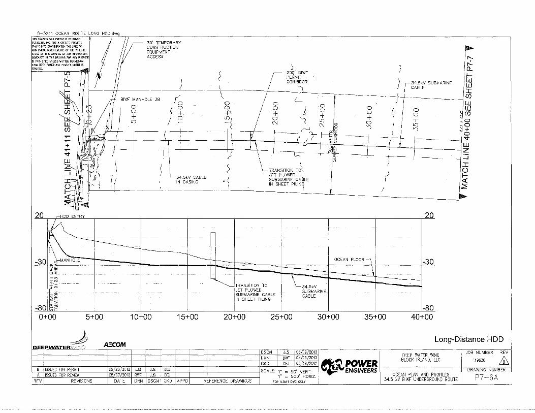
8-5X11 OCEAN ROUTE LONG HDD.dwg THIS DRAWlNG WAS PREPARED B't POII£R ENGINEERS, INC. FOR A SPECIFIC PROJECT, TAKING INffi CONSIDERA110N !l-IE SPECIFIC AND UNIQUE REQUIREMENTS OF lHE PRO.£CT. REUSE OF "THIS ORAVrlNG OR ANY INFORMATION CONTAINED IN lHIS DRAWING FOR ANY PURPOSE IS PROHIBITED l.NlESS YIRrmN PERMISSION FROM BOTH POWER AND POWER'S CUENT IS
30' TEMPORARY CONSTRUCTION EQUIPMENT ACCESS
~ f'-.
I f'-.
-® 1 ) I a_ I-
/ 34.5kV SUBMARINE w CABLE w
I BIWF MANHOLE 38 ;:_
0 0 0 0 + + li)
0 0 l '+ 0 '( ('J
0 0 + li) ('J "' 0
_f y I ~ 6 7 I ~.(:5 L \ I 1 co·~ 'lf--1--- , ~ . I <:>lhW
r--1 n::9 t. I ) ') I l'
8-5X11 BIWF.dwg THIS ORA'MNG WAS PREPARED BY POID \
~ ~~ -:----.__ ENGINEERS, INC. FOR A SPECIFlC PROJEC1, __..;
TAKING INTO CONSIDERA110N THE SPECIFIC \ \ /'1.'-Ck-o' ?. AND UNIQUE REQUIREMENTS OF lHE PRO..ECT.
\ \ kNors; · Ftoo0
REUSE OF THIS DRAVIING OR ANY INFOOMATlON
\ (R£F: ~-CONTAINED IN THIS DRA'MNC FOR ANY PURPOSE
f.tr. " TID£" 'AffrJ>RIDcr
~ IS PROHIBITED UNLESS WRITIEN PER~ISS10N
\ \~ Book 201J;ILor
'b~ FROM BOTH POWER AND POWER"S CLIENT IS
I r_ 200' BIWF co GRANlEO. \ Cb~ 0.2-:;;----.. \ PERMIT I
I (KNori,; E:aa CORRIDOR 1:- 1'--0..
\ ' )
~ 1:- ·-
\ <-> I ( \ \
il \ I-
I w
r:l \ lo\"" o 8\ 0 w 0 0 I ~\ \ \
0 10 0 + + + + + D'\ C/)
~ \ \) IL() ~ o 0 L() 0 r--.. r--.. w
~ '- X:, L() L() . OCD
~ w '-</~ ~«<v I ~\ I ' /'~ - C/)
I .. !/'~~¥; a1/.:V-Js wo O..y I ::;ou 0
~ Lr \ t o>- l 0
(~ \ I I '\. ~~ - +
"' I~ 0 ~ \ ' I co
<:<"<<v 1>"' [f) ~ 'i7o \ I <:<"<<v w
X I 34.5* ~ L\ z Oo \ I SUBM RINE
&~ ".] \ CABLE {~ .....J
I I ~& I I l \ ()
7~ I-,, ~ <( ~)' , c§0 ~
~ / . \\ '&
llc\ ~
10 10
I
I
I
-40 -40 OCEAN FLOO!i
[\ -~------r----~ ~--===--- - ----------34.5kV -----~------SUBMARINE ~-------90 CABLE -90
40+00 45+00 50+00 55+00 60+00 65+00 70+00 75+00 80+00
J AE'COM DEEPWATER•PJir·JC::· DSGN I JJS 103/19/2012
DEEP WATER WIND JOB NUMBER I REV DRN I BWF I 03/19/2012
~~POWER BLOCK ISLAND, LLC 119630 &
CKD I DEJ I 03/19/2012 8 ISSUED FOR PERMIT 05/23/2012 JJS JJS DEJ SCALE: 1" = 50' VERT. _;\,ENGINEERS DRAWING NUMBER A ISSUED FOR REVIEW 05/07/2012 BWF JJS DEJ 1" = 500' HORIZ. OCEAN PLAN AND PROFILES P7-7 REV REVISIONS DATE DRN DSGN CKD APPD REFERENCE DRAWINGS FOR 8.5x11 DWG ONLY 34.5 kV BIWF UNDERGROUND ROUTE

8-5X11 BIWF.dwg
~~N:~NI~C~~:RAE?S~~Fl~yp~6:r, ,, ~ S!.A~ ~o TAKINO INTO CONSIDERA]ON lHE SPECIAC ,.,.C) (kNOTs) ,J F'Looo AND UNIOOE REQUIREMENTS OF THE PROJECT. , V t.f. REUSE OF lHIS DRA~NO OR ANY INFORMATION '\ '\ (R£F, £L ~ • ~ ......_ CONTAINED IN THIS DRAW!NC FOR ANY PURPOSE f).;'\.. 8ilD£ ANo0~1fGt Q ,.,.... IS PROHIBITED UNLESS WRJTIDJ PERMISSION OOJ( 2012) OT Q M p FR" BOlH POWER AND POWER'S CUENT IS ....__ -:. 2 0) ORANTED. 0 2· O. ---... *- I
!"-.. ""'''iiii (kN;r; <ee - £L ~ 1'\--- / "" ""' 0 \ g 0 ( tJ 1- \ 0 // 0 ""' g ""' ~ ~ J; ~ g ""' w W '\.. o o + o '\ 0 o + \ :r: w '\.. + I + \;LD '\,.0 "' '\..'\.. i ~ LD '---... Cl) I LDI o m ~ 0 ~ ~ 'w (f) '-- co ' m 6' "\. "'~ Y ~ W W "'" r , J\ -----=-- " \:;j(S 'k - l>h (/) '\ l '\_ B!WF'-V-J7 '\, :::;:0 U - ~')< W ~ I ~ ~ o (f) I ~ '\.. J!51~ '\.. _\ o 0 "\,_ \ n. ~ '3' ~'\.., + O- (.11~ '-o 6 l...... \ \ lYP£112 ~ '\.., '\.... 34.5kV ~ CO TYPE 213 \, '--. '\.., \ '\.. '\.. '\.. SUBMARINE W W \' ...._ '\.. \ '\.., CABLE Z z '\.., '\, \.'\.., -1
_J '\ '\.._::, \ ' ~ - "'\. "_, :r: ~ - \._ 200' BIWF ~ .._, PERMIT ~ CORRIDOR ~
~~ ~ ~0 ~0
I I I I
~0 ~0
~----r--------:r=--.:::-r----------1\ ·-~--------- OCEAN FL OR~ I \_34.5kV I ---~ I
SUBMARINE I r----==-:::::---- i CABLE - ~---:--·===:t=-~--+----_J
-130 ---=r------~-----130 80+00 85+00 90+00 95+00 100+00 105+00 110+00 115+00 120+00
J_ DEEPWATER.N:r·.JD A;;COM
DSGN JJS I 03/19/2012 DEEP WATER WIND JOB NUMBER I REV
~~--------~--~~-~-~-~-~-+-------~D~~~+~B~V~I~~~/~19~fi~0~12~- ~~D~ 11~ A ~~----------------+='-7~~~+-~~~+---+---~------------~C~K~D~~D~EJ~\~03~/1~9/~2~01~2 ~.1 ~~Jl ' ~
B ISSUED FOR PERMIT 05/23/2012 JJS JJS DEJ SCALE: 1'' = 50. VERT _;\,ENGINEERS DRAWING NUMBER A ISSUED FOR REV1EW 05/07/2012 BWF JJS DEJ 1" = 500' HORIZ OCEAN PLAN AND PROFILES P7 8
~EV REVISIONS DATE DRN DSGN CKD APPD REFERENCE DRAWINGS roR a.S,11 owo oNLY . 34.5 kV B!WF UNDERGROUND ROUTE -

5-5X11 BIWF.dwg
1HIS DRAWING WPS PREPARED B'l' POWER ~ ENGINEERS, INC. FOR A SPECIF1C PROJECT, TAKING INTO CONSIDERAllON tHE SPECIFIC AND UNIOUE REOUIREMENlS OF 1HE PRo.ECT. R8JSE OF ntiS ORAVr1NC OR ANY INFORMATION CONTAINED IN THIS DRA'MNC FOR ANY PURPOSE IS PROHI8!1ED UNLESS WRITTIN PER~ISSION FROM BDlH POWER AND POWER'S CLIENT IS GRANTED. r 200' BIWF
PERMIT CORRIDOR
~x'
,Cl
,,~ ")C)
cq '(: 0 0'7 0 \ 0
0 0 + L[) "<t
.>7·
/
8 +l
0'7,
oo--~
r 0
~;
~ 'i
~ o \~ Jo 0 'J; + +
..!r" o-, L() J I o 1.0 ,A n "' 2fJ -<t ~ ry ..-- /0~..--
<-' J'E, ;_;l ..--
-r<?E. ~12
5SI ,_1 r T<I'E. u.J
-80
(f)
'& (f) ~
~ -r ~
-
<"
'% ::l {) ~ ~
-130f--
-180
I I "' I \ ~s
I - 1\ ---_L 1- ---+-- \ ~ \ ~~
"---' ~I'E:'I"
--........ ---..r-' v....._
~
~ ~
\ Jl ./\.../' I
I
I
I
I ~ [,
"'"' j SUBMARINE/ CABLE I
------SLACK-0.3 FLOOD
(KN01S)
(REf· Q.DRIOGE TJO( AND PILOT socK 20\2)
------o.z-0.7 EBB (KN015)
)
I I
-80
"""""' ~ =f= . . , ___ __,___. -t. _____..,_-~ ::r------r-J-130 "·'"' I I .
. '"""'"' I c~~ I
I I I I I -180 120+00 125+00 130+00 135+00 140+00 145+00 150+00 155+00 160+00
l , __ ,,_, __ _ ~ AECOM I I I~~~ .. I .. ~ DEEPWATER'i'f,:f·.JD I
V..Jj l::lfLVIL DEEP WATER WIND
03/19/2012 BLOCK ISLAND, LLC 03/19/2012
B I ISSUED FOR PERMIT 05/23/2012
u.J (J)
0 0 + 0 co ..,... w z _J
I 0 1-<(
~
4~POWER ;\,ENGINEERS
05/07/2012 OCEAN PLAN AND PROFILES A I ISSUED FOR REVIEW REV REVISIONS DATE REFERENCE DRAWINGS 34.5 kV BIWF UNDERGROUND ROUTE
I JOB NUMBER REV
119630 ffi DRAWING NUMBER
P7-9
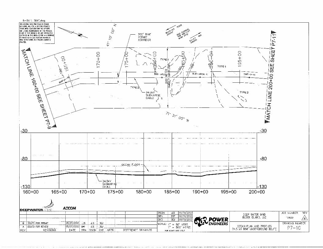
8-5X11 BIWF.dwg THIS DRA'MNG WAS PREPARED BY PO\\ffi < ~ oo'V ENGINEERS. INC. FOR A SPECIFIC PROJECT.
~ ~" TAKING INTO CONSIDERAllON THE SPECIFIC ~
,...o ,Dr;,<:..~ AND UNIQUE REOUIREMENlS OF 1HE PRO.ECT. a ~ REUSE OF lHIS DRAWING OR ANY INFORMATION a r ,oo· "''"'
e;.\..~'-~-r,?"'' ~'0~ ?, ...... o CONTAINED IN THIS DRAWING FOR ANY PURPOSE l:!"'o \.~'-'-\: •"llc''W ~ IS PROHIBilED UNLESS WRIT1EN PERMISSION 2 PERMIT ~~oo~ 'J.: o:1 ...--FROM BOTH POWER A'JO POWER'S CliENT IS CORRIDOR o~c'"'
I
GRANTED. f'.... - Q_ "1-
~ ~ -....,_ I I \- ,_
0 "-. 0 0 ' /1~ 0 w ~ o r..:::------o / I 0 w 0
+ ~ """ /TB / \ + \_ J: q_ + L() (/) -'1 0 iC l/\ L();, ~ CJ) \10 ['- ~ (?' ~t' )! II/ ~ 7YPE 1
w c t.P ~ ~ w
~ ... <------ I ~ f':! 0:: " .I I (/)
v WF-ARc~@ ~I /j BIWF-ARCH-1 1 ~ BIWF-V-40 -0
~~/~ I 0 .-> l \ 8~ I 11 \ \ +
~ <o~' ~I ly 0 I \ '\ -
~ 7YPE2 0
~ 34.5k~
""' ('\J
\~/ \ 7YPE2 w % ~ SUBMAR'E \
~ '"' z CABLE \l
~ \ '-...) ._j
<dl /-- \ '\
""' J: u
~ )'7. ,_
.37' <( ,....). oo" 2 '"'t} w ~ -l ~
-30 -30
I -80 -80
OCEAN FLOOR -
~ . ::±:: l----=::r- --~
---1--------------- ---34.5kV
I I -130 SUBMARIN
-130 CABLE
160+00 165+00 170+00 175+00 180+00 185+00 190+00 195+00 200+00
J ~COM DEI'PWATERJ\';r.cD DSGN JJS I 03/19/2012
DEEP WATER WIND JOB NUMBER I REV DRN BWF I 03/19/2012
~~POWER BLOCK ISLAND, LLC 119630 &
CKD DEJ I 03/19/2012 8 ISSUED FOR PERMIT 05/23/2012 JJS JJS OEJ SCALE: 1" = 50' VERT. ;\;,ENGINEERS DRAWING NUMBER A ISSUED FOR REVIEW 05/07/2012 BWF JJS OEJ 1" = 500' HORIZ. OCEAN PLAN AND PROFILES P7-10
REV REVISIONS DATE DRN DSGN CKD APPD REFERENCE DRAWINGS FOR 8.5x1 1 DWG ONLY 34.5 kV BIWF UNDERGROUND ROUTE

B-5X11 BIWF.dwg ll-!ts DRAMNG WAS PREPARED BY POWER
/7• ENGINEERS, INC. FOR A SPECIFIC PROJECT, ~"{\.Prj:) TAKING INTO CONSIDERAllON THE SPECIFIC ~Jo' < AND UNIQUE REQUIREMENTS OF THE PRO.ECT. Jo" w ~Q REUSE OF lHIS ORAVIINC OR 1.NY INFORMATION •
CONTAINED IN lHIS DRAWING FOR ANY PURPOSE .,_:~o"\'i>~ ,<P:.,, a ~ IS PROHIBfTED UNlESS WRITIDI PERMISSION
Ew ~ ~ ..... -v~'?·~ • ..o a
FROM BOTH POWER AND POWER'S CUENT IS (j'~t >""o,il N GRANTED. L 200' BIWF ~0~ 8? ~
O"""'flf PERMIT oor:F ~oo'O I
~ . - CORRIDOR c-~~~~ ,_ ,...._
< TYPE a... I "<;j-,...._
• 0 I
/......._ 'If"" I-a... J? 0 '--« I- + 0 [ \ 0 fJ-- c
Jo w
0 w w
' 8? 1.[) + ...._y + 0 0 I :r: w 0 0 \ 0
(\J TYPE2 1.[) + + 0 (/) :r: -'f (\J 0 1.[) ) + 0 \ (/) (\J ~ 0:: (\J 0 + w
I 1.[) w w 0 (\J ''J
l7 - §l_ f (\J 1") (/) w " (\J
0 (/) - wo 7 BIWF-V 41 0
~ - G :::>;'0 - -0 - o>- - +
0 TY~ _g~ \j---7
0 + \ 15 v 0 N 0
(I) - -N
~ w
~.SkY TYPE1 2: w BMARINE 2: '--- \ ABLE -l
/ :r: -l _./ () :r: I-()
-~<( I-~~ ~
-30 ~ -30
I I I -80
OCEAN LOOR~ -80 '\.
l34.5kV
:------ - -
I
--===---I SUBMARINE
CABLE
-130 -130 200+00 205+00 210+00 215+00 220+00 225+00 230+00 235+00 240+00
J AECOM ER"\'ifD DSGN I JJS I 03/19/2012
DEEP WATER WIND JOB NUMBER I REV DRN I BWF I 03/19/2012
~~POWER BLOCK ISLAND, LLC 119630 .ffi
CKD I OEJ I 03/19/2012 B ISSUED FOR PERMIT 05/23/2012 JJS JJS DEJ SCALE: 1" = 50' VERT. _i\, ENGINEERS DRAWING NUMBER A ISSUED FOR REVIEW 05/07/2012 BWF JJS DEJ 1" = 500' HORIZ. OCEAN PLAN AND PROFILES P7-11
REV REVISIONS DATE DRN DSGN CKD APPD REFERENCE DRAWINGS FOR 8.5x11 DWG ONLY 34.5 kV BIWF UNDERGROUND ROUTE

B-5X11 BIWF.dwg THIS DRA'MNG WAS PREPARED BY PO\\ffi ~
ENGlNEERS, INC, FOR A SPECIFIC PROJECT, ~
TAKING INTO CONS!DERAllON THE SPECIFIC ~ < ~ "fvoO'O ,...,.., AND UNIQUE REOUIREMEN1S OF 1HE PRO.ECT. '-- ..J REUSE OF lHIS DRAW!NC OR ANY INFORf.IATlON ~ ...-0 '\"""-CONT~NED IN 1HIS ORAWTNC FOR ANY PURPOSE I? ~'{..;,~ o«- ,..!. IS PROHBITED UNlESS WRimN PERMISSION \:!-'<' .;;Ji-\'V\\ • .0~ Q_ FROM 801H POWER "'0 POWER'S CUENT IS O::J «.~. ;,<> • ~ GRANTED. r 200' BIWF C) ~<>"-~~o''> /--
..- ._ PERMIT S2_ .,oo .,., W
..- CORRIDOR MP '"- 1 "' W 1 5 "1- .,....o·.,~
/'-.. 0 - oif"'.a~" :C
:: + g ) ;7 d iZ tH I ~ c5 1 + g 0 0 ~-w
:r: 1
N 1.[) J L,o~ o + .-----52 OTYP£ \ Cl) N (.{) 1.[) / ,__ + 2 O
Cl) 1- - - N @5 (.{) / R --- ......._!.[) ) 0 tH BIWF-V 42 v - f5 ~ N / N ~ j c5 Cl) j__ -t::;@5 I - -...... --/ co
I t :=ECJ - N 0 TYPE2 I o>- 11 - W
~ I g~ ~\£ 2: 0 I I!§ 11 ----o .4 '<:I" )',. [/) r r--v-- _J
N Jo' \ TYPE 1/2 34.5kV I W Jo•· 1,, SUBMARINE O 2: _ vv ) CABLE TY f-_J / ~ :r - j / l!o!.....-2 0 ------------ ~ f- ----------------
~ ..... ~0 ~0
I I I
-80 -80 OCEAN FLOQR -~
__ -i' __ ....... __ ----
............_;..__ -----,- -- I ---
\__ 34.5kV I I I -130 ~~~~:RI~E I I -130 240+00 245+00 250+00 255+00 260+00 265+00 270+00 275+00 280+00
J D ER,··;i~ .AECOM
DSGN I JJS 103/19/2012 DEEP WATER WIND JOB NUMBER I REV
~4---------~--+-4-~--~-~_4 _______ ~D~~~-HIB~W~F-~II02V~1~~~2~m~2~- B~~~D~ 119~ A ~~~~~~~-----+~~~~-+~-r~,_--+----r------------+C~K=D--~ID=EJ~/0~3~~~9/~20~12 ~-' P()~Jt ' ~
B ISSUED FOR PERMIT 05/23/2012 JJS JJS DEJ SCALE: 1 .. = so' VERT ~ENGINEERS DRAWING NUMBER A ISSUED FOR REVIEW 05/07/2012 BWF JJS OEJ 1" = 500' HORIZ OCEAN PLAN AND PROFILES p 7 1 2
REV REVISIONS DATE DRN DSGN CKD APPD REFERENCE DRAWINGS FOR a.5,11 owo oNLY • 34.5 kV BIWF UNDERGROUND ROUTE -
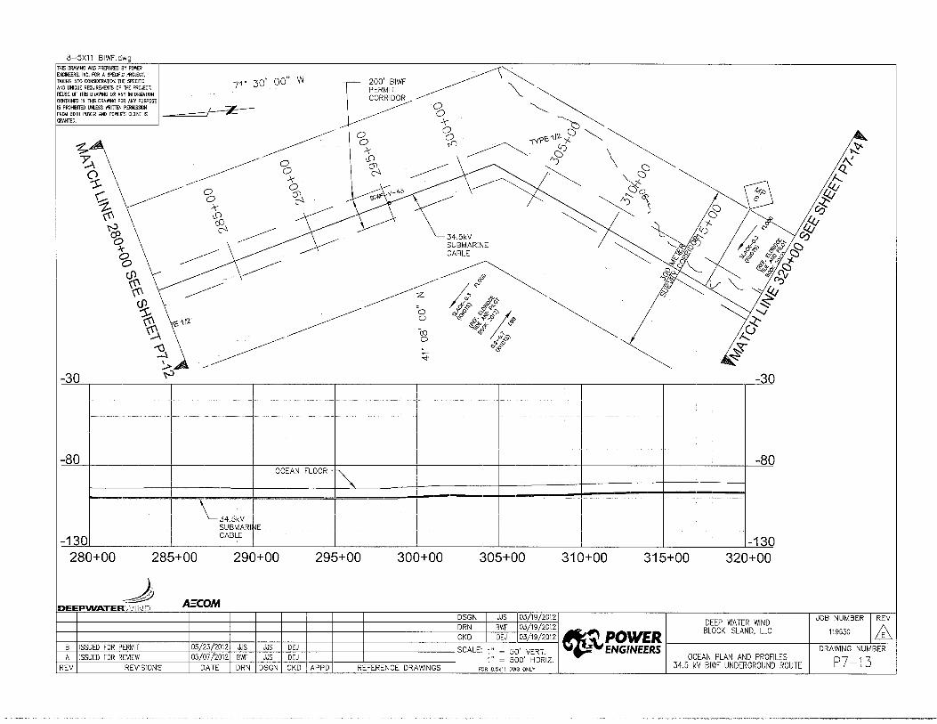
B-5X11 BIWF.dwg lH!S ORA'MNC WAS PREPARED BY POID ENGINEERS, INC. FOR A SPECIF!C PROJECT, TAKING INTO CONSIDERAllON li-IE SPECIFIC AND UNJQUE REOUIREMEN15 OF THE PRO.ECT. REUSE OF THIS ORAVr1NG OR ANY INFORMATION CONTAINED IN llHS ORA\IJING FOR ANY PURPOSE IS PROHIBilED UNLESS WRimN PER~lSSION FROM BOTH POWER AND POWER'S CUENT IS GRANlED.
~· ~ ~ ~ ~ ~ ~ '6
-30
<& ~
~ ~ .:.A
~
I
I
·I I
-80
r====== I
-1301 I
71· 30' oo" w 200' BIWF PERMIT CORRIDOR ~~
/ z-
~ 0 0 .lr '.0
~
~
.;;_'.12
~ 0 0
.>r 0
~
0 ~~~ 6 I'{P"- ~12 '/. 0 §~~
0 ~ \ ,0~ ~0 0
~ ~0 · ~ Go
~~~ ~A
34.5kV SUBMARINE CABLE
~ /~
/rf~ ~~~ 0 «.,.$)~ .v
~ ~ ,;~ ~~;,;7"'~., ~ ~&o- ~
ro ~ ;j~ ~ ; o<£
OCEAN FLOOR
~ = --·--- --
\_,," r SUBMARI E I
I CABLE I
-30
-8C
-
-13C
~ .'{'{
.'J......Q l!! ~ ,0
·4J 0
280+00 285+00 290+00 295+00 300+00 305+00 310+00 315+00 320+00
J DEEPVVATER·i·J:i·.J [' AECO.M
='7-'-+~;:-t.;;0~3]T.19""/ic20~1;;.!2 DEEP WATER WIND JOB NUMBER REV 03/19/2012 ~- BLOCK ISLAND LLC 119630 1\ 03/19/2012 :.1 POWER · LQ..';.
r--:B:-+1=-ss=-u=Eo:-=:Fo::::-R-.:P=ER=-M=Ir,-----+=-=-=+--:-:::-+---:c::-+-:-::-:-t--+-----+-------+.:.c:::_-J__:.::.:..-'-""-'""-"~ ..i\, ENGINEERS DRAWING NUMBER
A ISSUED FOR REVIEW OCEAN PLAN AND PROFILES p 7 1 3 REVISIONS 34.5 kV BIWF UNDERGROUND ROUTE -

8-5X11 BIWF.dwg lHIS DRAWING W~ PREPARED B'f POWER ENG1NEERS, INC. FOR A SPECf"IC PROJECT.
TAKING INTO CONSIDERAllON THE SPECIFIC LL AND UNIQUE REOUIREMENlS OF 1HE PRO..ECT. x;:.." R£1JSE OF TillS DRAWING OR ANY tNFORMATION CONTAINED IN Tilts DRAWING FOR ANY PURPOSE Q~ IS PROHIBfTED UNLESS WRITTEN PERMISSION _, FROM BOTH POWER AND POWER'S CUENT IS l)>:_ GRANlED. 0<
-30
-80
~ ~ I 0 0
r--- Ia o o ~ + + r d~ m o W ;,g N I"J w di$ I"J J I"J I ~ ==c ~ C/)
w w C/)
0 0 + 0 N C'? w z _J
I 0 r <-ell!!! 2
TYPE 1/2 ,, ~
' ')() . ')()
1"
),t- TURBINE #1
-~"
,, ~ ' ')()
')()
200' BIWF I PERMIT
-----------77L____jL-COR~R 0
~ TURBINE #1
+ + o m "<!- 0:: .q-
g ~ g rv; 0 rv; --n::9--~f§
\___
lUO
~~~ 0~ ""a::
;::, (/)
34.5kV SUBMARINE CABLE
8
1: ~-><12 <>o "<z V:¢.
~5 I 0~ lll
§;~ EB
'""'" u.: ~ ":in' ~~8 o:; '-'~CD j~
1.{) .--,..:_ a_ 1-LJJ ------0 0
0 0
lJJ .r (/)
+ + 0 1.{) 1.{) 1.{) rv; rv; --
lJJ lJJ (/)
0 0 +
----..10 co (Y)
~ TYPE 1/2 ~ -:.,Y lJJ ~
(._..... --.....__._
\..v ~ '----.. /'..._
OCEAN FLOOR \
TURBINE #2r--.
\
-.1
.r 0
"--"'. 1-
-L___~ -30
-80
~---~---~----r---r~-r----r---~----1 I M~
CABLE
I
I , SUBMARINE
-130 -130 320+00 325+00 330+00 335+00 340+00 345+00 350+00 355+00 360+00
J DEEPWATERic':r.cD .AECOM
DSGN 03719/2012 DEEP WATER WIND
03/19/2012
~~POWER BLOCK ISLAND, LLC
03/19/2012
B ISSUED FOR PERMIT ;\, E.NGINE.E.RS A ISSUED FOR REVIEW OCEAN PLAN AND PROFILES
REV REVISIONS FOR 8.5x11 DWG ONLY 34.5 kV BIWF UNDERGROUND ROUTE
JOB NUMBER REV
119630 ffi DRAWING NUMBER
P7-14

B-5X11 BIWF.dwg llits ORA'MNG WPS PREPARED BY PO\IrtR ENGINEERS. INC. FOR A SPECIFIC PROJECl,
/~ '* TAKING INTO CONSIDERA110N THE SPECIFIC ,,
AND UNIQUE REOUIREMENlS OF THE PRO..ECT. ()() t-REUSE OF THIS DRA'NINC OR ANY INFORt.lATlON CONTAINED IN THIS DRA'MNC FOR ANY PURPOSE
"J' 8 IS PROHIBllED UNLESS WRimN PERMISSION
I~ ~~" \ ~ "<"--FROM BOTH POWER AI'JD POWER'S CLIENT IS
""'" r-!.. GRANTED.
'¢~ L 200' BIWF ['""'" ,, 1'1 ~oO Q ~"G' ct~t"l r- .......
PERMIT ~g tj~g 1'~ I-...- ---;-7
coRRmoe vlC. .!S.Fm d:=.. I w
1'-0 \0
w 0.... 0 0 J: I- + + 0 0 T .,._
TYPE 112 + 0 0 \ - (f) lU L() 0
1.[) + 0 ~ ·-w lU w " + 0 n n ['... 0 w I n CD 1.[) 6~ \ 0 (/)
Cf) -
I- -7- CD + lU n 0:: (]) \ 1.[) 0
IWf-'i 45 ~ n ~g 0 lU
~ 1 --
I 0:: - + Cf) f-'0:: I 0 wo 1-0
.:::;o - 0 - BIWF-V 46 '<:j-0 ~ + '0> - - w 0
0:: -:::> - z (0 "' -(") 34.5kV
TYPE 112 '* _J
lU SUBMARINE J: _J_ v--.-_. '\ CABLE
,, z l</. ":>() 0 :J - -- 0.>, I-
--~ "J' <:(
I ""'" ~ C)
o-, ~ ---- ~ I- ---~
-30 <t;~ -30 ~
I I /
----TURBINE #3 I OCEAN FLC
OR\ I
-80 -80 '1.
-~~ - ==--------· ·-- I ~4.5kV I I I I
SUBMARI~E
-130 CABLE I
-130 360+00 365+00 370+00 375+00 380+00 385+00 390+00 395+00 400+00
J .AECOM DEEPWATER'i•J:f·.JD DSGN JJS 103/19/2012
DEEP WATER WIND JOB NUMBER I REV DRN BWF I 03/19/2012
~~POWER BLOCK ISLAND, LLC 119630 &
CKD DEJ /03/19/2012 8 ISSUED FOR PERMIT 05/23/2012 JJS JJS DEJ SCALE: 1" = 50' VERT. ~ENGINEERS DRAWING NUMBER A ISSUED FOR REVIEW 05/07/2012 BWF JJS DEJ 1" = 500' HORIZ. OCEAN PLAN AND PROFILES P7-15
REV REVISIONS DATE DRN DSGN CKD APPD REFERENCE DRAWINGS FOR 8.5x11 DWG ONLY 34.5 kV BIWF UNDERGROUND ROUTE

B-5X11 BIWF.dwg
~ ,,
"':;\)
, ......
-30 I
I
-80
200' BIWF MIT
:IDOR
~TURBIN~ #4
~
"' 'to\3 \"' 1') ~~-s ~ ~~ ~2~ t-.'Vi \ ~~ ~~~ '1.~ u\~ .:;...>~IS) 0~
OCEAN FLOOR_}
1\"
~ ,, \)\)
"Jcv
_'1
TURBINE #5~
--T\----0 0 + lD f'l)
""""
TUR~INE #5~~
·--
(j)
I'
+ co f'l)
"""" b
---
-30
-80 f---- I -- --j..,.....=-~ I T--~=:--4-----
1 I
I SUBMARINE CABLE
-130 -130 400+00 405+00 410+00 415+00 420+00 425+00 430+00 435+00 440+00
)) ~
DEEPWATER \''l·l'J ~COM 03/19/2012
DEEP WATER WIND 03/19/2012
~~POWER BLOCK ISLAND, LLC
03/19/2012 05/23/2012 _;\,ENGINEERS 05/07/2012 OCEAN PLAN AND PROFILES
DATE REFERENCE DRAWINGS 34.5 kV BIWF UNDERGROUND ROUTE
8 I ISSUED FOR PERMIT A I ISSUED FOR REVIEW
REV REVISIONS
JOB NUMBER 1 REV
119630 ffi DRAWING NUMBER
P7-16

U2-1 UTILI1Y CROSSING.dwg THIS DRAWING WJ.S PREPARID BY POWER ENGINEERS, INC. FOR A SPECIFIC PROJECT, TAKING INTO CO~IDERA110N THE SPECIFIC AND UNIQUE REQUIREMENTS OF THE PROJECT. REUSE OF THIS DRAWING OR Atff INFDRMA110N CONTAINED IN THIS DRAWING FOR ANY PURPOSE IS PROHIBITED Ut'l.ESS WRITIEN PER~ISSION
FROIA BOTH POWER AND POWER'S CUENT IS GRANlED.
0' TO 30'
Co
J D ER.\''i<D
EXISTING UTILilY
20' TO 60'
PLAN VIEW
20' TO 60'
CONCRETE MATS TO BE PLACED ON EACH SIDE OF CROSSING
~ PROPOSED MARINE CABLE
EXISTING UTILilY
PROFILE VIEW
20' TO 60'
EXISTING UTILITY CROSSING £COM SCALE N.T.S.
SEA LEVEL
0' TO 30'
PROPOSED MARINE CABLE PROPOSED SAND BAGS
CONCRETE MATS SEA FLOOR
EXISTING UTILI~
1 f
U"1 w 0:: ;:s
~
~
CROSS SECTION
SEA FLOOR
.,::.=;::.:..:...+--=::--+0::;3t.,./1c:,9/c;:2:.:..01'72 DEEP WATER WIND JOB NUMBER REV 03/19/2012 1\
~~=~~=~--~~=~~~~+=+-+-+------~=~~~~~~~~o~3L/~1~9~/~2~o~12~~~R ~~~ill 11~ ~ B ISSUED FOR PERMIT .;\,ENGINEERS DRAWING NUMBER A ISSUED FOR REVIEW UTI LilY CROSSING DETAIL U 2 1
REVISIONS 34.5 kV BIWF UNDERGROUND ROUTE -

U2-2 SHALLOW PENITRATION.dwg THIS DRAWING Wf.S PREPARED BY POWER ENGINEERS, INC. FOR A S?EaFlC PROJECT, TAKING INTO CONSIDERATION THE SPECIFIC AND UNIQUE REOUIREMENlS OF lHE PROJECT. REUSE OF THIS DRAWING OR AN1 INFORMAllON CONTAINED IN THIS DRAWING FOR ANY PURPOSE IS PROHIBITED UNLESS WRmEN PERI.liSSION FROM BOTH POWER AND ?OWER'S CUENT IS GRANlED.
J ER"\<'ii<D
ISSUED FOR PERMIT A ISSUED FOR REVIEW
REV REVISIONS
kCOM
"o I
-<.0
"o I
:.,-
MARINE CABLE
PROPOSED MARINE CABLE
PLAN VIEW
"o I
:.,v
PROFILE VIEW
CONCRETE MATS MAY BE INSTALLED OVER THE CABLE WHENEVER A MINIMUM OF 4' -0" OF COVER IS NOT ACHIEVED (SEE NOTE 1)
SEA LEVEL
CONCRETE MATS MAY BE INSTALLED OVER THE CABLE WHENEVER A MINIMUM OF 4'-0" OF COVER IS NOT ACHIEVED (SEE NOTE 1)
NOTES:
(f) w
~
SEA FLOOR
SHALLOW PENETRATION DETAIL
1. ROCK DROPPING WITH SIMILAR PROFILE MAY BE USED IN LIEU OF CONCRETE MATS WHERE TARGET DEPTH WAS NOT ACHIEVED.
SCALE N. T.S.
vc
DSGN 03/19/2012 DEEP WATER WIND JOB NUMBER
+:1:-=-:/"'':::-:/;;::::"'~-=-~::l....,~""·;;=-~-+..,..~~--:-+--::,...;+l --+1 --1-1 -------I,.C::~~~A~~L-E:_L_N_':ON:'::E'--l:O::~~'j_:~.C::L'.:~':::~.'.::~~ A~~~~~ BLOCK ISLAND, LLC 119630 1-- · ·--·-1 -- 1 1 1 ' \il~ I SHALLOW PENETRATION DETAIL DEJ
CKD I APPD FOR 8.5x11 DWG ONLY 34.5 kV BIWF UNDERGROUND ROUTE I U 2-2 REFERENCE DRAWINGS

U2-3 Erosion Control.dwg lHIS DRAWING WftS PREPARED BY POWER ENGINEERS, JNC. FOR A SPEOAC PROJECT, TAKING INTO CONSIDERATION THE SPECIFIC AND UNIQUE REOUIREJJ:ENlS OF THE PROJECT. REUSE OF 11-US DRAWING DR ANY INFORMAllON CONTAINED IN THIS DRAWING FOR Am PURPOSE IS PROHIBilED UNLESS WRITTEN PERMISSION FROM BOTH POWER AND POWER'S CUENT IS GRAN'TED.
NOTES: ~RMWATER INLETS WHICH DO NOT DISCHARGE TO
SEDIMENT TRAPS OR BASINS MUST BE PROTECTED UNTIL THE TRIBUTARY AREAS ARE STABILIZED.
2. SEDIMENT MUST BE REMOVED FROM INLET PROTECTION AffiR EACH STORM.
3. REFER TO LONG TERM/SHORT TERM MAINTENANCE NOTES FRO TIMING OF PLACEMENT AND REMOVAL OF EROSION CONTROL ELEMENTS.
NOTE: REGULAR FLOW=40 GAL/MIN/SF HIGH FLOW=ZOO GAL./MIN/SF
EXPANSION RESTRAINT 1/4" NYLON ROPE
2"x2"x3/4" RUBBER BLOCK
NOTES: 1. SHAUl. BE IN ACCORDANCE WITH SECTON 206 OF
THE R.I. STANDARD SPECIFICATIONS. 2. 2''x2"x4'-5''(MAX.) OAK POSTS FOR SILT FENCE
SHALL BE LOCATED 8' -0" (MAX.) D.C. IN WETLAND AREAS AND 4'-o" (MAX.) O.C. IN WETLAND RAVINE. GULII.Y OR DROP-OFF AREAS AS SHOWN ON PLANS.
3. 1 "x1 "x4'-6"(MIN.) POSTS PERMITTED FOR PRE-FABRICATED SILT FENCE.
4. SILT FENCE SHALL BE INSTALLED BEFORE ANY GRUBBING OR EARTH EXCAVATION TAKES PLACE.
.. _l'ROTECTED AREA
METAL CONNECTOR CABLE 1/8"¢ (MIN.)~
2"x2"x4' -5"(MAX.) OAK POST DRIVE IN TRENCH (SEE NOTE 2)
. ;,:~(1 1'-SLIT FABRIC AND LOOP ::' ~ : : CABLE OYER POST
SILT FENCE FABRIC
EXISTING GRADE
DETAIL "A"
SILT FENCE DETAIL NOT TO SCALE
_J SILT SACK DETAIL NOT TO SCALE
DE ~TERNii<:l') A.:' COM 03/19/2012 03/19/2012
~~POWER 03/19/2012 B ISSUED FOR PERMIT ..i\i ENGINEERS A ISSUED FOR REVIEW
LIMIT OF CLIEARING
HEAVY-DUTY CORD SEWN IN SILT FENCE FABRIC (TOP AND BOTTOM) (SEE DETAIL "A" FOR TOP CORD FOR EVERY OTHER SILT FENCE POST)
MIN.
DEEP WATER WIND JOB NUMBER REV
BLOCK ISLAND, LLC 119630 ffi DRAWING NUMBER
EROSION CONTROL DETAILS REV REVISIONS REFERENCE DRAWINGS 34.5 kV BIWF UNDERGROUND ROUTE U2-3

U2-4 Bridge Delail.dwg 1HIS DRAWING W/U PREPARED BY POWER ENGINEERS, INC, FOR A SPEaFlC PROJECT, TAKING !liTO CONSIDERATION THE SPECIFlC AND UNIQUE REQUIREMENlS OF ll1E PROJECT. REUSE OF lHIS DRAWING OR ANY INFORMATION CONTAINED IN THIS DRAWING FOR mf PURPOSE IS PROHIBnED Ut>lESS WRI1TEN PER1r11SSION FROM BOTH POWER AND POWER'S CUENT IS GRANTED.
)~ ~
DEEPWATER\i'/iNr-;
ISSUED FOR PERMIT A I ISSUED FOR REVIEW
REV I REVISIONS
(7) ANCHOR BOLTS
2" TUBE STEEL
CONDUIT SUPPORTS
w G 0 [2 co LL 0
w 0 0 w
.AECOM
05/23/20121 BWF I JJS I DEJ 05/07/20121 BWF I JJS I DEJ
DATE I DRN IDSGNI CKD IAPPD
w 0 0 [2 co LL 0
BRIDGE CROSS SECTION
LOOKING EAST
DSGN DRN CKD
SCALE: NONE
03/19/2012 03/19/2012 03/19/2012
REFERENCE DRAWINGS FOR 8.5X11 DWG ONLY
w G 0 [2 co LL 0
w 0 0 w
~~POWER .z ENGINEERS
DEEP WATER WIND BLOCK ISLAND, LLC
BRIDGE DETAIL 34.5 kV BIWF UNDERGROUND ROUTE
JOB NUMBER REV
119630 & DRAWING NUMBER
U2-4

U2-5 Coffer Dam Detail.dwg THIS DRAWING WAS PREPARED BY POWER ENGINEERS, INC, FOR A S?EaFlC PROJECT, TAKING INTO CONSIDERATION THE SPECJFIC AND UNIQUE REQUIREMENTS OF THE PROJECT. REUSE OF THIS DRAWING OR M« INFORMATION CONTAINED IN THIS DRAWING FOR ANY PURPOSE IS PROHJBilED UNLESS WRITTEN PERMISSION FROM BOTH POWER Af\JD POWER'S CUENT IS GRANIDl.
0 I ,_
il
12" HDPE\ t;:;;r: CONTUIT 'j' '-' 6::
INSTALLED "i.e ~ ~ BY HDD
IDEEPWATJ:RJ
>CD
JfP\ JJ\ offi offi offi offiJT\JT\.JT\.JTWT\JT\JT\ o ~
H PILE HP--------. 14X73 -----.....
WALE & STRUT HP
14X73
MLLW\
CONCRETE""'
PANELS ""'
EXCAVATE" AS NEEDED "'
CONCRE1E~
PANELS ""'
5D'-D"
::r ~
I I I II I
\~\I/n~~~~~~
PLAN SCALE N.T.S.
SHEETING AND WALE NDT SHOWN FOR CLARrrY 20' X 50'
VCOFFERDAM STAYS IN PLACE UNTIL CABLE IS
"rr ec~ I '"'~"' AFTER EXCAVATION AND BEFORE CABLE ~ /INSTALLATION, CUT SHEET
~ ~~~ I ~ . . NATURAL BOTTOM
'<'.i0'):;..v '\._ Jl I v;:cv,"-v'50v)0~~'-C /~~ ""- . ~0:*~0<~ ~~ ! ~~~~~~/ . '.' ' '»'» "» "~» '\ /A~ 20 ~~~~~<:::<~ ·v~ >v; , , y»;XY;XY~,~~ /~~, ~«~~'V("«'0\.«'«'V(vv-0(v'0<.~«"</.-?( ~«~~~Y. ~~ >0;~~~~~~~"0~~~~~~~~~~ >%~~~~~· .~'« ~~~"«~'«~~'«~~'«~~'«~~~ ~~v:~,'-. ~~ /(~«<~~~~~~~~~~~~<?<~~<( ~<:::<«>Y/ / A~~) ~/'" "-~~~~~~~~)»~~')»')»'>Y»> /'" ·' ;i0>"" ' '"(<~~~~'-.~ '' . '-. . '- SHEET PILE TIP----..
// ELEVATION TBD '-
ELEVATION VIEW A.:'COM SCALE N.T.S.
=:::..:....-i-.:::.::--+0:::3/<;1'-='9/c;:2:::_01~2 DEEP WATER WIND JOB NUMBER REV 03/19/2012 BL K 1\
~+=~~=~--~~~d~4~+=+--l--+------:=~~~~~~~~o~3~/~1~9~/~2:::D~12~~~ ocs~~ill 11~ ~ B ISSUED FOR PERMIT ~ENGINEERS DRAWING NUMBER A ISSUED FOR REVIEW COFFERDAM DETAILS u
REVISIONS 34.5 kV BIWF UNDERGROUND ROUTE 2-5

U2-6 Submarine Detail.dwg lHIS DRAWING WAS PREPARED BY PQINER ENGINEERS, INC. FOR A SPEOF!C PROJECT, TAKING INTO CONSIDERAllON lHE SPECIFIC AND UNIQUE REQUIREMEN15 OF "THE PROJECT. RaJSE OF 11-IIS DRAWING OR Am INFDRIIAllON CONTAINED IN THIS DRAWING FOR ANY PURPOSE IS PROHISilED UNLESS WRITTEN PERMISS1DN FROM BOTH POWER AND POWER'S CliENT IS GRANTED.
aR1 MLL~~ /1 1 r l Ill
,..------. ]I ~. /TcK~LL To BE NATURAL
SEA FLOO\ 5' -0" SEDIMENT DUE
I TO JETPLOW
'""""'"~~ / 6'-0" TARGET BURIAL DEPTH
U> CABLE w
~
SECTION SCALE N.T.S.
SEA FLOO~ EXCAVA~\ JET PLOW
NEEDED ~ 6'-0" TARGET ""- Jl BURlA.L DEPTH
SUBMARINE CABLE_/
ELEVATION VIEW SCALE N.T.S.
J AECOM DEEPVVATER·h·:r·.J D DSGN I JJS 1D3/19/2012
DEEP WATER WIND JOB NUMBER I REV DRN I BWF ID3/19/2012
~~POWER BLOCK ISLAND, LLC 119630 &
CKD I DEJ 103/19/2012 B ISSUED FOR PERMIT 05/23/2012 BWF JJS DEJ SCALE: NONE ~ENGINEERS DRAWING NUMBER A ISSUED FOR REVIEW 05/07/2012 BWF JJS DEJ SUBMARINE CABLE INSTALLATION DETAILS U2-6 REV REVISIONS DATE DRN DSGN CKD APPD REFERENCE DRAWINGS FOR B.5x11 DWG ONLY 34.5 kV BIWF UNDERGROUND ROUTE

U2-7 Manhole Detail.dwg THIS DRAWING WAS PREPARED BY POWER ENGINEERS, INC. FOR A SPECIFIC PROJECT, TAKING INTO CONSIOERAT10N THE SPECIFIC AND UNIQUE REOU!REMEtmi OF lHE PROJECT. REUSE OF THIS DRAWING OR Am INFORMA11DN CONTAINED !N THIS DRAWING FOR ANY PURPOSE IS PROHIBilED UNLESS WRITTEN PERIAISSION FROI.t BOTH POWER AND POWER'S CUENf IS GRAN1ED.
w 61"' :r: I z -<: ,..., :;;o
b CJ>
LU -U \JU >UK ~U MANHULt.)
s'-o" 5'-o" 5'-o" 5'-0"
r-----l------t------r-----1 I I I I I I
+----+-1 I I
I : I
0:: 0 Lo.
·o
I 3'-o" I 3'-o" I ~I"' ' I cr ~ r-
I I j -'----'--+-~- - - - - - - - - - - - - r - - - - - - - - - - - -
(o I
"'
pLAN v1 Ew r BRICK CHIMNEY / GRADE OR PRECAST RING
& il (
~------------------------l
I I I I I I I I I I I I I I
~-rl ________________________ j
MANHOLE SECTION VIEW
J DEEPWATER'i·.·:r·.Jr> AECOM
03/19/2012
4'-0"
r-~ ~~.; .J 3'-10"
'o I
"" lJ........l>.A~~ B • • B
50' FIBER pLAN OPTIC PIGTAIL
1_ ___l
COVER
{ ~ rn=======J[J~ SECTION
I 4" MOUSEHOLES
SECTION A (ONE EACH SIDE)
NOTE QUAZITE 48"x48" PG COVER AND BOX MADE FROM POLYMER CONCRETE.
FIBER OPTIC HAND HOLE SCALE N.T.S.
DEEP WATER WIND
B
REV 03/19/2012
~~POWER BLOCK ISLAND, LLC ffi 03/19/2012
B ISSUED FOR PERMIT _;\;,ENGINEERS A ISSUED FOR REVIEW MANHOLE DETAILS U2-7 REV REVISIONS REFERENCE DRAWINGS 34.5 kV BIWF UNDERGROUND ROUTE

U2-B TRENCH DErAIL ALUMINUM.dwg lHIS DRAWING WAS PREPARED BY POWER ENGINEERS, INC. FOR A SPECIFIC PROJECT, TAKING INTO CO~IDERA110N lHE SPECIFIC N'lD UNIQUE REOUIREMENlS OF lHE PROJECT. REUSE OF THIS DRAWING OR Am INFORVATION CONTAINED IN THIS ORAWIN(; FOR ANY PURPOSE IS PROHIBilED UNLESS WRITTEN PERMISSION FROM BOTH POWER AND POWER'S CliENT IS GRANTED.
J ER\i•i:r·.!r>·
ISSUED FOR PERMIT A I ISSUED FOR REVIEW
REV REVISIONS
-"' lz: 1--N ::;j;'
';.-,
-"' II~ -N ::::E
AECOM
~
05/23/2012 05/07/2012
DATE
DOUBLE CIRCUIT SECTION SCALE N.T.S.
(2) 6" WIDE RED WARNING TAPES
(4) 4" PVC CONDUITS
NGRID
(8) 5" PVC CONDUITS
THERMALLY APPROVED CONCRffi MIX
03/19/2012 03/19/2012 03/19/2012 ~~POWER
_;\, E.NGINE.E.RS
DEEP WATER WIND JOB NUMBER REV
BLOCK ISLAND. LLC 119630 ffi DRAWING NUMBER
TRENCH DETAIL U2-8 34.5 kV BIWF UNDERGROUND ROUTE

8-5X11 BIWF.dwg THIS DRA'MNG W/15 PREPARED B'l' POYoffi ENGINEERS, INC. FOR A SPEClFIC PROJECT, TAKING INTO CONSIDERA"TION THE SPEctFlC AND UNIQUE REOUIREMENlS OF THE PRO..ECT. REUSE OF THIS DRAWING OR ANY INFORMATION CONTAINED IN THIS DRAWING FOR ANY PURPOSE IS PROHIB11ED UNLESS WRITTEN PERMISSION FROM BD1H POWER AND POWER'S CLIENT IS GRAN lED.
I~ ~ ~ ~LIMITS OF WORK
IY ~;: "-. 34.5kV BITS ~~~ :::__ DUNE LINE /;"
i' '""' SUBMARINE I 30' TEMPORARY CONSTRUCTION EQUIPMENT ACCESS
TRANSITION TO JET PLOWED SUBMARINE CABLE IN SHEET PILING
0 I ~
--;,
/i I~ &
~~
~ I CABLE IN I
' CASING ,'
-.- I // /. ~= / II [ PRO~SED / ' BITS MANHOLEi P.ERMANENT - _-::::_/:__ __
~ 'r' \\ ~ASEMENT --~--~----~ .• ----- ( . ··-•
_?_ ___ ,_l:r.;::_.' .. -··\_ ~ t-1
~u-..... i ___ £::.--~---- ' ~ "=t- ~I b ----------- ~ = L_
\II 0 i= ===~==~==~~u=~-=----------------,---------\--\--- ~ ...... tt· ............... } .... ............................... \" .. ~ ..... ...... ,tllllllllllllllllllll:::llllllllllllllllllllllllllllll~ a 6 a::
"' Ed :z: :z: a:: 0 u l r i \
.~ \ ,. ~
': \ I~ \
I I \
ll ,~ \
i j
~ j ~ ,!' i:>ol.!.-~,.fl~J!•I ..
/ ~
i'""II•H•li•II•H• ""-.. ____ _.,....-- ~/"* i ___ 11-rt.;;lioir.IDoTJlO'n.nr•~~·
j-.. -~--
1
J~ -~ kCOM
---~·-----+-- -~----~+ l/ \ \ : TRANSITION TO i: \_ PROP~ED ----7 If. JET PLOWED i~- PERMA ENT SUBMARINE CA,LE i EASEM NT IN SHEET PILIN
I. \ 34.5kV BIWF I : ' ; : BIWF MANHOLE • SUBMARINE I '"""-- MEAN AVERAGE I !1 1\ \ .{ g~~I~GIN I : HIGH WATER I
t-::~~"\ I I ! J: \ \\ I - I ~I . ,' DUNE LINE
J I // \\\1 / ;/; I ~ ( ~\ \\ \- /; I
/)L·~--,~~ ~ / rul._il ( / ~ I I '
03/19/2012 DEEP WATER WIND
JOB NUMBER 03/19/2012 BLOCK ISLAND, LLC 119630 03/19/2012
REV
ffi ISSUED FOR PERMIT
4~POWER ~ENGINEERS DRAWING NUMBER A ISSUED FOR REVIEW BLOCK ISLAND LANDING U2-9 REV REVISIONS 34.5 kV BIWF UNDERGROUND ROUTE