urban mesh and ad hoc mesh networks
TRANSCRIPT

Copyright © 2008 John Wiley & Sons, Ltd.
Urban mesh and ad hoc mesh networks
Anders Nilsson Plymoth1,*,†, Ulf Körner1 and Per Johansson2
1Department of Electrical Engineering and Information Technology, Lund University, Lund, Sweden2University of California, San Diego, California, USA
SUMMARY
Mesh networking is currently gaining much attention, within both academia and industry. Mesh networking allows cheap and fast deployment of wireless services. It is regarded as a very promising solution for urban deployment scenarios as well as for temporary emergency response situations. Another related promising fi eld is that of ad hoc wireless networking, which consists of mobile nodes that dynamically create and maintain a network without the need for any infrastructure. We propose a solution and architecture for urban mesh ad hoc networks, a network that combines mesh networking with ad hoc networks for urban environments. We present four types of ad hoc mesh and ad hoc mesh networks. The most general one consists of mesh nodes, called mesh points (MP), that act as a type of access point for user nodes (UN). The MPs have at least two interfaces: one which is used to communicate with UNs, and one which is used to maintain the mesh access network and transport data. These two interfaces can basically use any type of technology (IEEE 802.11 a/b/g, WiMax, etc.), and for capacity reasons it is generally regarded that the best solution is to let the mesh interface operate on a separate high-capacity channel or channels. An intricate part of these types of networks are routing and location services. In our solution, UN devices operate in ad hoc mode running an ad hoc routing protocol. This allows UNs that wish to communicate to connect directly in an ad hoc manner, or through an MP. An important question is therefore whether two UNs that wish to communicate should connect through the mesh or connect directly. We show that from a capacity point of view whether a UN should route its packets to the closest available MP, or through a ad hoc network, depends on the environment the network is located, the amount traffi c and the type of protocols used. Since MPs need to know where to route packets within the mesh, i.e., locating the MP closest to the destination UN, each UN run a small application that registers the UN to the mesh network. In addition to the above features we have developed a new MAC that quickly queries two candidate nodes, which picks the candidate with the currently best radio conditions. This enable nodes to cope with deep dips in signal strength due to fast fading, a well-known problem in urban environments. We show that this new protocol achieves signifi cantly lower delays. We also show that in dense urban environments performance and battery lifetime can be improved if ad hoc technologies are used. Copyright © 2008 John Wiley & Sons, Ltd.
1. INTRODUCTION
Wireless mesh networks is an area that has been receiving much attention within the last few years. They can be considered as wireless networks where each node can function both as an access point and as a router responsible for forwarding traffi c from other parts of the network. Wireless ad hoc networks are another type of wireless network that is closely related to mesh networks. The main difference between mesh and ad hoc networks is that ad hoc networks are constructed by user terminal nodes and these user nodes are expected to be highly mobile, whereas this mobility aspect has led to an extended amount of research performed on the topic of mobile routing, because as the user nodes move around in the network the network topology will constantly be changing. Within this topic, IETF has had a very important role, resulting in the standardization through experimental RFCs of a couple of routing protocols.
INTERNATIONAL JOURNAL OF NETWORK MANAGEMENTInt. J. Network Mgmt 2008; 18: 107–127Published online 2 January 2008 in Wiley InterScience (www.interscience.wiley.com) DOI: 10.1002/nem.681
*Correspondence to: Anders Nilsson Plymoth, Department of Electrical and Information Technology, Lund University, Box 118, SE-221 00 Lund, Sweden.†E-mail: [email protected]

108 A. N. PLYMOTH, U. KÖRNER AND P. JOHANSSON
Copyright © 2008 John Wiley & Sons, Ltd. Int. J. Network Mgmt 2008; 18: 107–127 DOI: 10.1002/nem
While ad hoc networks are still waiting for a killer application into the commercial market, mesh network devices are already available through different manufacturers. Mesh networks are built as cost-effective wireless access networks and have been deployed in some cities as wireless MAN networks.
Mesh networks are also considered a promising technology for emergency, search and rescue opera-tions. This is because mesh networks can be rapidly deployed and be made to need little or no confi gu-ration. With well-confi gured mesh devices, the only thing an emergency team needs to do to get a fully operational access network is to bring the devices to a location, turn them on and distribute them in the area. This is especially useful in areas where very little communication infrastructure is currently avail-able or where the communication infrastructure has been destroyed.
This paper focuses on both ad hoc and mesh networks, and on a combination of the two. We investi-gate how well these types of networks can be expected to be operational in a typical city environment and in a type of suburban environment. As far as we know, this is the fi rst simulation study of ad hoc/mesh networks in an urban setting that takes into account fading and walls of different buildings, in combination with different well-known routing, MAC and physical layer protocols. We also present and analyze a new MAC and a new routing protocol that are more sensitive to the current radio condi-tions. A well-known problem in urban city environments is the effect multi-path propagation has on the received signal strength. While the effects this fast fading has on the physical layer is well known, and is taken into account by most physical layer protocols, it has not yet been properly addressed on the network layer. The traditional view of a network link is that either it is up or it is down, and this must be handled properly by the routing protocol. The wireless routing protocols proposed by the IETF take into account that links can rapidly appear or disappear as nodes move around in the network. What they do not address is that the quality of links over a wireless fading channel fl uctuates heavily. This means that while a link may be unusable due to heavy fading, it may be so for only a few milliseconds. The failure of a data packet over a wireless link may therefore be the result of the channel being in a deep fade rather than the link being unavailable.
This paper therefore also presents a type of forwarding called diversity forwarding. It is based on the idea that if one link is currently unavailable due to fading, it may be possible to use another available link with a currently better communication channel.
We therefore also analyze mesh networks that use standard routing and MAC protocols, in an urban setting with fading channels, and compare them with our newly proposed protocols. We also analyze a combination of mesh and ad hoc networks, where user nodes connect to the mesh network over several hops. This means that user nodes need to use ad hoc routing in order to reach the mesh access network.
1.1 Related work
The performance of mesh networks has been studied previously, although not in ad hoc and urban scenarios. In Ganguly et al. [1], the authors investigate the performance of VoIP traffi c in mesh networks and study the number of supported calls. By using packet aggregation and header compression, they increase the number of supported VoIP calls to about 30 for one hop and 10 for three hops. Ramachandran et al. [2] analyzes interference and the performance throughput of Constant Bit Rate (CBR) connections in mesh networks.
Another very active research area is that of multi-channel protocols for wireless and ad hoc networks. This topic has been presented in many papers, which differ mainly on how they control access to the dif-ferent channels; comparisons of some of the schemes can be found in Mo et al. [3] and Wormsbecker and Williamson [4]. These are most often designed as scheduled access protocols, where the MAC scheme con-trols which channels can be used and when. Some schemes are more opportunistic or use physical or virtual carrier sensing [5–7] to determine the channel, while some use busy tones [8] or channel hopping [9].
Several papers have recently discussed the topic of diversity forwarding. One of the fi rst protocols written on this subject was the 2001 paper ‘Selection diversity forwarding’ (SDF), by Larsson [10]. This scheme works by fi rst letting a node broadcast the data packet to a subset of potential relay nodes, listed

URBAN MESH AND AD HOC MESH NETWORKS 109
Copyright © 2008 John Wiley & Sons, Ltd. Int. J. Network Mgmt 2008; 18: 107–127 DOI: 10.1002/nem
in priority order. These nodes send back acknowledgement messages, and based on this information the node takes the forwarding decision. This decision consists in electing one of the potential relays as the actual relay node. This scheme was later modifi ed and updated in their ‘Multiuser diversity forwarding’ (MDF) paper [11]. In MDF, a small probe pilot is fi rst used that indicates potential relays, which after reception of the pilot reports their perceived channel quality back to the sender. The sender then deter-mines the next hop based not only on the channel state, but also picking the appropriate fl ow and rate. A main difference between SDF and MDF is that in MDF the evaluation is conducted before the data packet is actually transmitted. Several other papers have presented similar protocols that specify various MAC and network layer schemes for diversity forwarding [12–19]. This paper presents a protocol that operates on principles similar to those used in MDF. It also uses a simple channel-hopping scheme, as will be explained.
2. URBAN MESH AD HOC NETWORK TYPES
Depending on the type of network and node architecture used, we can defi ne a number of mesh ad hoc network architecture types (Figure 1). The type of map we are considering is a Manhattan city grid.
2.1 Pure ad hoc networks
The pure ad hoc network is a network that only consists of user nodes equipped with a single wireless interface running an ad hoc routing protocol. This type of network is typically connected through a single MAC and PHY technology operating on a single channel. If the routing protocol supports routing over multiple channels, a multi-channel solution is also possible. The advantage of this solution is that it is very simple. All that is needed is a device with wireless capabilities running an ad hoc routing protocol. The disadvantage is that in an urban environment the network must cover a large geographical area and therefore many links. This will put a severe strain on available resources but the performance may still be acceptable for some types of applications, such as voice or text messaging. In the future the available bandwidth and bit rate might be suffi ciently high, making this type of solution acceptable also for other type of applications.
2.2 Supported ad hoc networks
This architecture is very much like the pure ad hoc network, but with the addition of some fi xed and static support nodes. The support nodes are placed at strategic locations in the network and aid the network by forwarding routing and data traffi c. Since these nodes will be fi xed, their placement can be planned in such a way as to help maintain good connectivity throughout the network. In the pure ad hoc network the user nodes are all assumed to be mobile, and the connectivity of the network can therefore not be guaranteed. The support nodes should be placed at locations that maximize general connectivity or in locations that normally have a low user node density.
2.3 Single-hop mesh networks
This is currently the most common type of mesh network. The network consists of mesh points (MPs) equipped with at least two wireless interfaces. The MP is connected in a dedicated routed network used for the transport of user data. The MPs maintain the mesh network using one wireless interface, while communicating with the user nodes on another interface. User nodes in the network are equipped with only one wireless interface, which it uses to communicate directly with a specifi c MP.
If the wireless interface of the user nodes is of 802.11 type, the interface can be made to operate in either infrastructure mode or ad hoc mode. If the interface of the user node and MP operates in infra-structure (association) mode, no special software or confi guration is needed. The user can then use the

110 A. N. PLYMOTH, U. KÖRNER AND P. JOHANSSON
Copyright © 2008 John Wiley & Sons, Ltd. Int. J. Network Mgmt 2008; 18: 107–127 DOI: 10.1002/nem
802.11 confi guration applications provided by all modern operating systems (OSs) and connect to the urban network as if it was a normal 802.11 access point.
There is nothing that prevents the 802.11 user nodes and MPs from operating in ad hoc mode. However, in this case some other applications are needed that determine the existence and address of an MP, and accordingly confi gure the node and the network interface information. In this case, the user node can also be made to communicate with other user nodes directly. If an ad hoc routing protocol is running, these other user nodes could also be reached over multi-hop routes.
2.4 Urban mesh ad hoc networks
In this type of network every user node runs an ad hoc routing protocol. Every MP also runs this protocol on at least one of its interfaces. The MPs also run another routing protocol to confi gure the mesh part of the access network. A typical feature here is that user nodes can connect to the mesh network through MPs over multi-hop routes, using other user nodes as relays.
(a) Pure Urban Ad Hoc Network. (b) Supported Urban Ad Hoc Network.
(c) Urban mesh network. Nodes access the network in asingle hop.
(d) Urban Mesh Ad Hoc Networks. Nodes canaccess the network through multihop routes.
Figure 1. The four network types

URBAN MESH AND AD HOC MESH NETWORKS 111
Copyright © 2008 John Wiley & Sons, Ltd. Int. J. Network Mgmt 2008; 18: 107–127 DOI: 10.1002/nem
3. MESH NETWORK REGISTRATION APPLICATION
Every user node runs an application that registers the user node’s address to an MP. This registration is needed by the mesh network to keep track of the current location of user nodes in the network. Every MP maintains a list of all its currently registered nodes, and periodically exchanges this information with the other MPs. This allows every MP to know the location of every user node in the network.
3.1 User node data transmission
When a user node has data that it needs to transmit, it tunnels its data packets to its currently registered MP. The packet is routed towards the MP using the ad hoc network routing protocol used by all user nodes. When the packet is received at the MP, the MP determines which MP the destination address belongs to, and tunnels the packet to this destination MP. If the destination IP address is not found in the MP registration list, and the IP address doesn’t belong to the user node subnetwork, the packet is tunneled to the Internet mesh point gateway (IMPG), if such an MP is available. When the data packet is received at the destination MP, it is detunneled and routed to the fi nal destination using normal ad hoc routing.
3.2 Mesh point registration procedures
When a user node joins a mesh network, it fi rst needs to determine what MP it to register to. If no local MP is known, the node may broadcast an MP search message. If an MP receives the search message, it will respond by sending an MP search reply. However, MPs will periodically broadcast an MP advertisement message with the IP TTL or hop limit fi eld set to 1 (see Figure 2). Each user node (UN) that receives this message will update its MP list with the corresponding information about the MP: the MP address, the distance in hops, the lifetime of the advertisements, the sequence number, and the announce time (i.e., the current time). User nodes will use this list to determine the best point of attachment (i.e., the best MP) to the network, and to determine when a handover is needed to a new MP.
The purpose of the advertisements and the search replies are for user nodes to learn about the existence and distance to different MPs. An important question, when we have an ad hoc network structure, is how this information should be disseminated across multiple hops. One possibility is to increase the TTL or hop limit to an appropriate value and then let each user rebroadcast the message upon receiving it. The main problem with this approach is that every UN that receives an advertisement needs to rebroadcast it. For example, if fi ve nodes are located within the one-hop range of an MP, they will hear the same advertisement fi ve times, possibly within a short time frame. If one of these nodes is within range of fi ve additional two-hop nodes, it will hear the same advertisement fi ve more times, and so on. As the network spreads over many MPs, and every advertisement with an active TTL will be rebroadcast, a lot of advertisements will be spread over the network.
A simpler solution is to let each user node send their own advertisements with the TTL or hop limit value set to 1, instead of rebroadcasting advertisements from MPs. The number of advertisements a node overhears within a time frame will then be bounded by the node density: the number of nodes located within communication range of the node. This process can ideally be coordinated with different neighbor discovery processes, used by many different protocols, as it provides information about the state and existence of different neighbors. The exact details about this, though, is beyond the scope of this paper.
When a user node determines that it needs to register with the network, it searches its MP list for the MP that it determines to be the most appropriate, and issues an MP registration request. How to
Type Mesh Point Address User Node AddressCurrent Distance Sequence Number
Figure 2. The fi elds of the mesh point search reply and mesh point advertisement message
112 A. N. PLYMOTH, U. KÖRNER AND P. JOHANSSON
Copyright © 2008 John Wiley & Sons, Ltd. Int. J. Network Mgmt 2008; 18: 107–127 DOI: 10.1002/nem
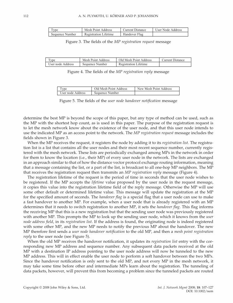
determine the best MP is beyond the scope of this paper, but any type of method can be used, such as the MP with the shortest hop count, as is used in this paper. The purpose of the registration request is to let the mesh network know about the existence of the user node, and that this user node intends to use the indicated MP as an access point to the network. The MP registration request message includes the fi elds shown in Figure 3.
When the MP receives the request, it registers the node by adding it to its registration list. The registra-tion list is a list that contains all the user nodes and their most recent sequence number, currently regis-tered with the mesh network. These lists are periodically exchanged among MPs in the network in order for them to know the location (i.e., their MP) of every user node in the network. The lists are exchanged in an approach similar to that of how the distance vector protocol exchange routing information, meaning that a message containing the list, or a part of the list, is broadcast to all one-hop MP neighbors. The MP that receives the registration request then transmits an MP registration reply message (Figure 4).
The registration lifetime of the request is the period of time in seconds that the user node wishes to be registered. If the MP accepts the lifetime value proposed by the user node in the request message, it copies this value into the registration lifetime fi eld of the reply message. Otherwise the MP will use some other default or determined lifetime value. This message will update the registration at the MP for the specifi ed amount of seconds. The handover fl ag is a special fl ag that a user node can use to make a fast handover to another MP. For example, when a user node that is already registered with an MP determines that it needs to switch registration to another MP, it sets the handover fl ag. This fl ag informs the receiving MP that this is a new registration but that the sending user node was previously registered with another MP. This prompts the MP to look up the sending user node, which it knows from the user node address fi eld, in its registration list. If the address is found, the originating node is indeed registered with some other MP, and the new MP needs to notify the previous MP about the handover. The new MP therefore fi rst sends a user node handover notifi cation to the old MP, and then a mesh point registration reply to the user node (see Figure 5).
When the old MP receives the handover notifi cation, it updates its registration list entry with the cor-responding new MP address and sequence number. Any subsequent data packets received at the old MP with a destination IP address pointing to the user node address will now be tunneled to the new MP address. This will in effect enable the user node to perform a soft handover between the two MPs. Since the handover notifi cation is only sent to the old MP, and not every MP in the mesh network, it may take some time before other and intermediate MPs learn about the registration. The tunneling of data packets, however, will prevent this from becoming a problem since the tunneled packets are routed
Type Mesh Point Address Current Distance User Node AddressSequence Number Registration Lifetime Handover Flag
Figure 3. The fi elds of the MP registration request message
Type Mesh Point Address Old Mesh Point Address Current DistanceUser node Address Sequence Number Registration Lifetime
Figure 4. The fi elds of the MP registration reply message
Type Old Mesh Point Address New Mesh Point AddressUser node Address Sequence Number
Figure 5. The fi elds of the user node handover notifi cation message

URBAN MESH AND AD HOC MESH NETWORKS 113
Copyright © 2008 John Wiley & Sons, Ltd. Int. J. Network Mgmt 2008; 18: 107–127 DOI: 10.1002/nem
directly to the new MP. After a while, the periodic registration list updates will see to it that the new user node location is known by every MP in the mesh network.
3.3 User node handover determination
An important decision that a user node needs to make is to determine when it is time to switch to a new MP. When a user node has an active communication through an MP, it will periodically send registra-tion updates that trigger registration replies. From the current distance fi eld of the registration reply, it can keep track of the distance (in number of hops) to its current MP. When this distance increases by one hop, it might be a good idea to initiate a handover to a new MP. If we consider the network topol-ogy, and what event it actually causes, the distance to the MP increases by one, then a link break has usually occurred. Some of the links on the route to the MP have broken, inserting an extra intermediate node into the route. If we consider a Manhattan topology, a likely scenario might be that the user node has rounded a corner, thereby causing the signal strength to rapidly drop, breaking the link to the next hop towards the MP. In this case it makes sense to start searching for a new MP on the new street. This is also our recommended action upon noticing the increased distance. When the distance has increased by one, the node issues a new MP search procedure, as described above. If a closer MP is discovered, a fast handover registration update will be issued, also as described above.
Since we are considering the case where a user node has an ongoing communication with an MP, a link break and the following increased distance will have an impact on the performance of the communica-tion session. If we have an option available from the OS that enables us to determine the signal strength (RSSI), of the last reception from our next hop towards the MP, we may have the option to proactively start searching for a new MP. Most OSs used today provide some form of RSSI support, and consider-ing the interest the research community has shown to these features, it may very well soon become a standard feature.
4. FADING AND FORWARDING IN THE MESH ACCESS NETWORK
Fading is something that has a signifi cant impact on the performance of wireless networks. This is some-thing that is especially true when the network is located in an urban environment.
4.1 Fading
Fading results from the superposition of transmitted signals that have experienced differences in attenu-ation, delay and phase shift while traveling from the source to the receiver. It may also be caused by attenuation of a single signal. A signifi cant result of fading is heavy fl uctuations of the received signal strength.
In mobile communication we often talk about two different type of fading: slow fading and fast fading. Slow fading is caused by the larger movements of a node and obstructions within the propagation path. For example, when a node is moving in a suburban or urban environment, buildings and trees will sometimes block the direct path between the sender and the receiving node. While the direct path is obstructed the signal strength will drop, and when the mobile has moved past the obstruction the signal strength will again increase. Fast fading has a more complex explanation. The reason for the fast fading signal loss is the destructive interference that multiple refl ected copies of the signal make with itself. To understand how a signal can destructively interfere with itself, consider how the sum of two complex sinus waveforms with different phases interleave.
Consider Figure 6. Here we see an example of the signal variations in a Rayleigh fading channel, when the mobile node is moving at 2.5 m/s. The small circlets indicate packet reception instants and we can see how large the signal variations are for this simple scenario. When we are in a deep fade it will not

114 A. N. PLYMOTH, U. KÖRNER AND P. JOHANSSON
Copyright © 2008 John Wiley & Sons, Ltd. Int. J. Network Mgmt 2008; 18: 107–127 DOI: 10.1002/nem
be possible to receive even at the lowest rate, while at good instants it will be possible to receive at the maximum rate.
4.2 Diversity forwarding and diversity MAC
In an urban wireless setting where both the environment itself as well as the mobile nodes themselves are moving, fading will affect the signal strength of every wireless link. This means that sometimes the link will be very good and sometimes very bad. In the wireless access mesh, it will often be possible for one MP to have several possible routes to another MP. This means that the MP may have several possible MPs as the next hop. If the link towards one next-hop MP is currently in a bad fading state, one of the other possible next hops might be in a better fading situation. So, if we have a mechanism that allows us to evaluate different next-hop candidates before the packet is actually transmitted, we could gain a lot both in terms of performance and power consumption.
Diversity MACWe present a MAC protocol that enables diversity forwarding and allows power and interference control by querying a number of possible candidate nodes. Each candidate is a possible next hop towards the fi nal destination as determined by the upper layer routing protocol.
In normal IEEE 802.11 DCF, a terminal may use a simple RTS-CTS cycle to inform its neighbors about an intended transmission. Nodes overhearing a RTS or CTS defer their transmissions for the duration of the scheduled transmission. In our protocol, we extend this functionality also to include diversity, power and channel information, into the RTS and CTS messages.
IEEE 802.11 specifi es that a number of different channels can be used. 802.11b/g specifi es three concur-rent channels, while 802.11a specifi es eight concurrent channels. In order to increase the effi ciency of the protocol, we also provide a simple mechanism to dynamically pick the best current channel. This means that control information is always transmitted on a predefi ned control channel (let us assume channel 1), while data traffi c can be transmitted on any channel.
Whenever a node wants to transmit a packet, it multicasts an RTS message that includes two or more destinations. It also includes information about the power level used when transmitting the RTS. Each
0 0.2 0.4 0.6 0.8 1Time (s)
-5
0
5
10
15
20
25
30
Rx
SIN
R (
dB)
Rayleigh Fading2.5 m/s 2.4 Ghz
Figure 6. Packet reception for a Rayleigh fading channel at 2.5 m/s mobility at 2.4 GHz

URBAN MESH AND AD HOC MESH NETWORKS 115
Copyright © 2008 John Wiley & Sons, Ltd. Int. J. Network Mgmt 2008; 18: 107–127 DOI: 10.1002/nem
destination receiving an RTS replies by sending a CTS in the order they are listed in the RTS. Just as with the RTS, the CTS also includes the power level used for transmitting the CTS. In addition to this, the CTS includes the power level Plevel needed for this node to successfully receive the scheduled packet. This power level is calculated based on the gain as perceived by the target node, and the current noise level. It is now also possible for the target candidate to calculate the expected SINR of the requested transmis-sion. Based on this the target picks an appropriate data rate. The data rate picked depends on the type of modulation and coding used by the different available rates. Different rates use different modulation and coding schemes with different minimum target SINR levels.
The target node also performs a multi-channel carrier sensing. This means that it fi rst senses every available data channel to determine which channels are idle. It can then randomly pick a channel among the idle ones, and specify this channel in the channel fi eld of the CTS. If no data channel is idle, the control channel can be used. However, in our simulations we use another approach, i.e., the data channel is mapped to the destination address, as explained below.
When the initiating node has received all the CTS messages it is expecting, or they have timed out, it chooses an appropriate destination, tunes the radio to the indicated channel, sets the corresponding and indicated power level and sets the data transmission rate.
An issue with this type of scheme is how to set the network allocation vector (NAV). In 802.11, the NAV is set by all nodes receiving either the RTS or CTS, and prevents these from transmitting for the duration of the scheduled transmission. In our case, it is very hard to set the NAV, for three reasons. The fi rst reason is that when the source node issues the RTS, it does not know the duration of the upcom-ing transmission. The duration depends on the data rate used, which is determined by the receivers, as explained above. This means that any neighboring node overhearing the RTS cannot set the NAV as it does not know the duration. Secondly, as the RTS is sent to multiple candidates, several CTS responses will also be generated. Neighboring nodes that overhear an CTS cannot determine whether this candi-date will be chosen or not. This decision is made by the initiating transmitter, which therefore prevents neighboring nodes from correctly setting the NAV. The third implication is that future transmitters might try to contact a node that is already transmitting on another data channel. This node is then not able to transmit to that particular target node. The result of all this is in that in our protocol RTS and CTS mes-sages do not set any NAV.
While it is not possible to set a NAV, it doesn’t have to be too bad. Since the RTS may be multicast to several candidates, one of the other candidates might be available. Thus, if one candidate is busy transmitting, some of the other candidates may still be free to accept the upcoming transmission. The requesting node has to consider the case that a failure to receive a CTS may be the result of the terminal being busy in some other transmission, perhaps on a different channel. This problem of a candidate target node being busy on a different channel is commonly called the hidden terminal channel problem. If only one candidate is used, the fact that the candidate may be busy on a different channel must also be taken into account when choosing the RTS timeout value.
Another issue here is that in normal CSMA/CA operation, as defi ned by 802.11, the time between consecutive RTS retries increases exponentially. A consequence of this is that if some other neighboring node wishes to transmit to the same target node, that node will initially start with a small random backoff value that depends on the default minimum contention window (CW). Since the fi rst node started with a small value that is increased for every failed attempt, and the second node comes into the game at a later point in time, that node will have a smaller backoff interval. The chance for the competing neighboring node to gain access to the target node therefore increases. In order to ease this situation a little, consider a node that is currently in a backoff after failed RTS. When it overhears an RTS from a neighboring node destined to the same target destination, it will reset its CW (reset its backoff timeout value to the default value). However, while this helps, it is still not enough. Some neighboring nodes close to the target, but out of transmission range of the initiator, might still be able to unfairly win in a situation like this.
To make the situation more fair, we therefore propose the following two approaches: (1) increase the CW only after every third failed attempt; (2) freeze the CW for the fi rst three attempts as in (1), but compensate for this by increasing the CW by a power of 4 after the fourth failed attempt.
116 A. N. PLYMOTH, U. KÖRNER AND P. JOHANSSON
Copyright © 2008 John Wiley & Sons, Ltd. Int. J. Network Mgmt 2008; 18: 107–127 DOI: 10.1002/nem
This will make the situation more fair among terminals competing for access to a node that is currently busy transmitting on one of the data channels. While this is a very simple approach, the drawback is that the probability for real collisions will be higher. If a node experiences severe problems, or if it determines that the node and traffi c density so demand, it might dynamically adjust the CW. How to dynamically set the CW has been studied in several papers. However, this is not something that we have currently implemented.
4.3 Multiple channels and planning
Most wireless technologies available on the market today provide the ability for radios to communicate on a multiple number of different channels. The MAC protocol we presented above is designed to option-ally use these channels as dynamically as possible. However, if a standard MAC protocol like 802.11 DCF is used, this fl exibility will not be available. This does not mean that nodes in the network have to operate on a single channel, at least not the MPs. Since the topology in a mesh network is typically static, smart network planning can enable the use of several channels.
A simple approach, which was presented in Wu et al. [20], uses a simple hash function to map a des-tination node to a specifi c channel. While this is not very dynamic, it is very simple and can achieve signifi cant performance improvements. This approach works in the following way: when a node is about to transmit a packet to a destination node, it uses the hash function with the designation IP address and tunes its radio to the corresponding channel. After transmission, it tunes the radio back to its own dedi-cated channel, as determined by its own IP address. We will evaluate this approach in our solution, in combination with standard routing protocols.
Diversity routingA very important part of achieving diversity forward is how we perform routing. This is important not only in terms of fi nding routes in the classical way, but also as a very important input to the MAC layer. The routing algorithm needs to provide the MAC protocol with different candidate next hop destinations. This type of routing also puts a new and different constraint on the routing protocol. It needs to provide multiple non-node-disjoint paths to a destination. In a normal link state routing protocol, single paths are set up through independent calculations of every node in the network. Loop freedom is assured by the fact that every node uses the same algorithm with the same input information. This will in effect create a single source destination path through the network. In our case, every intermediate node in the network will make an independent choice of which next node to send the packet. This means that preventing loops will become much more diffi cult and complex. One might think that source routing is a possible solution to this, but this means that only the source can take any path decisions. One possible solution, though, is to set up the route, or rather the multiple non-disjoint paths, when needed, and in the process ensure that loops will not be created. One solution like this is presented in Nilsson et al. [12]. While that paper presents a working protocol, some diversity is lost in the process of ensuring loop freedom. Another option is to use some form of route recording, either at the MAC level or at the IP level. This would enable each forwarding node to take the previous path into account when taking the forwarding decision. It would also effectively prevents loops. The drawback is of course the extra overhead, but with some intelligent address compression and address planning the overhead can be minimized. This is the approach we have currently implemented.
Diversity forwardingThe network routing protocol has to make the decision of what candidates to propose to the MAC layer. We do this by using standard shortest-path calculations (Dijkstra), but with the constraint that the forward path does not cross the previous path; that is, we will not allow any loops. This decision is then forwarded to the MAC protocol, which evaluates the proposed candidates in the way we explained above. The MAC layer will now decide the next hop based both on the information about the candi-dates it received during the RTS/CTS cycle and path information it received from the routing protocol.

URBAN MESH AND AD HOC MESH NETWORKS 117
Copyright © 2008 John Wiley & Sons, Ltd. Int. J. Network Mgmt 2008; 18: 107–127 DOI: 10.1002/nem
Basically, what happens is that the RTS/CTS-based information temporarily updates the network path costs. The reasoning is that, although if one candidate may have perfect link conditions, that candidate node has a bad forward path. Some other candidate nodes with only average link conditions may have a perfect forward path forward. We could say that the two protocols, the MAC protocol and the routing protocol, operate on different time scales. The MAC protocol operates on a short timescale, while the routing protocol operates on a longer timescale. It is the combination of both these timescales that will form the basis of the forwarding decision.
We believe this sharing of information across layers is very promising. The fast query reply probing on the MAC layer will enable us to perform diversity forwarding that will be effi cient in fading chan-nels. As the environment normally is constantly changing, especially in an urban environment, fading sensitive forwarding can be really helpful. If one of the candidates is currently in a deep fade, it will either not respond or it will respond and increase the path cost signifi cantly. Choosing another next hop in this case would make a lot of sense.
4.4 User node versus mesh node forwarding
User nodes use a slightly different type of forwarding. First, they only use diversity forwarding for packets routed towards an MP. Secondly, they only query two candidates, and these two candidates must be closer in number of hops to the MP. These candidates can be determined by listening to and analyzing the routing protocol control traffi c. When it hears a routing control message from a neighboring node, determines that it is using a route to the MP the node is currently using, and that node is closer to the MP, it will mark that node’s address as a possible next-hop candidate.
Another solution for a user node to determine possible next-hop candidates is to use information that it learns from the registration application that we described earlier. When the node forwards, or over-hears a message from a closer neighboring node, and that node is also registered or is registering with the same MP, it will mark that node’s address as a possible next-hop candidate.
The user node will then use the diversity MAC described above. The main difference here is that only the hop count metric is used. If the hop count to the MP through the candidates is the same, it will randomly select the one with the highest data rate. If the data rate is the same it will randomly pick one of the candidates.
5. SIMULATIONS
We have used the Qualnet simulator [21] to evaluate our proposed solutions and architectures. Qualnet is a popular commercial event-driven and scalable network simulator.
In addition to the Qualnet simulator, we have developed a small intelligent ray-tracing (IRT) tool that takes as input maps defi ned in Qualnet and outputs a tile-based propagation matrix. The IRT considers diffraction around corners and we use up to four refl ections to calculate the multi-path propagation, although more refl ections can be specifi ed if needed. The IRT technique divides the simulation area and all defi ned walls into a number of tiles. The propagation path loss from between every source destina-tion tile pair is then calculated and put into the matrix. For points within each tile we then use bilinear interpolation in order to get a better approximation within each tile and a higher resolution. The type of map we are considering is a Manhattan city grid, as described in the next subsection.
5.1 Simulation setup and scenarios
We will simulate the four network architectures we described earlier in Section 2. Each network type will be simulated in a 525 × 525 m urban city area, consisting of 100 nodes. The city is modeled according to the well-known Manhattan city topology model. For the fi rst two network types the node will consist of 100 user nodes. For the second network type only 75 of the user nodes will be mobile, while the other

118 A. N. PLYMOTH, U. KÖRNER AND P. JOHANSSON
Copyright © 2008 John Wiley & Sons, Ltd. Int. J. Network Mgmt 2008; 18: 107–127 DOI: 10.1002/nem
25 are static and placed at different intersections. The third and fourth network types consist of 75 user nodes and 25 MPs. The fourth ad hoc mesh network consists of nine mesh access points, with 16 mesh relay points. A mesh relay point only forwards mesh traffi c and operates on a different channel from that used by the user nodes.
Every node in the network will use 802.11g at the physical layer. The MAC protocol and routing pro-tocol will differ between the different scenarios as explained below.
While this simulation area might be smaller than what is normally used in ad hoc network simulation studies, it should be noted that the urban simulation area consists of 16 city blocks, where each block is a square of 100 m, intersected by 25 m wide streets. This area will produce a topology with an average hop count of about six to seven hops, which is signifi cantly longer than what is normally used in ad hoc simulation studies. The suburban environment consist of the same city topology, but here a block consists of many smaller and lower houses. MPs as used in the mesh topologies are placed above these houses, while user nodes are placed below. This means that for the suburban environment it might be possible for two user nodes to fi nd a connecting signal path through a city block. This is not possible in an urban environment, as the walls around the city block completely block the signal path, although the signal might be refl ected around corners and thus eventually reach the other user node.
The power consumption of each individual node is measured during each simulation. Different power values are used depending on whether the node is transmitting, receiving, sensing, or idle. These differ-ent power values are modeled after the Cisco Aironet 802.11 a/b/g chip [22].
In the fi rst network traffi c type we are simulating are a varying number of two-way 56 kbps CBR traffi c sources, modeled after the G.711 [23] codec.
A technique that can be used to predict user satisfaction of a conversational speech quality is the ITU-T E-model. The E-model is standardized by the ITU as G.107 [24] as a tool that can estimate the end-to-end voice quality, taking the IP telephony parameters and impairments into account. This method combines individual impairments (loss, delay, echo, codec type, noise, etc.) due to both the signal’s properties and the network characteristics into a single R-rating. This method can be used as a good quality-of-service measure for VoIP calls that consider a user’s opinion about the service. The mean opinion score (MOS) is a method recommended by the ITU and the IEEE 802.20 group [25] to measure speech quality. In this method, the users rate the call quality in a range varying from 1 (bad) to 5 (excellent). The rating will be applied both after the G.711 and the enhanced G.711 [26] codec.
In these cases we are simulating a constant random load of 5, 10, 15, 20 and 25 source–destination traffi c pairs. By constantly random we mean that the traffi c load on the network is constant, but that the source destination pairs are constantly changing. Each CBR fl ow is 1 minute long, and when one fl ow ends a new fl ow will instantly start between a new source destination pair somewhere else in the network. These simulations are running for a total of 60 minutes. These traffi c scenarios are designed to roughly model voice communications between two voice-capable devices, when the network is loaded by various amounts of traffi c.
For each simulation scenario and network type, user nodes will move according to the pedestrian mobility model defi ned in Qualnet 4.0. Here, user nodes move along the streets to a randomly chosen street corner somewhere on the city map. When the nodes arrive at their destination, they will randomly choose a new destination somewhere on the map. Every time they arrive at a street corner, they run a 50% chance of having to wait for a red light before proceeding across the street. Each pedestrian user node will move at a constant speed uniformly chosen between 1.5 and 2.5 m/s.
Radio signals will be affected by multi path fading according to the Ricean fading model, with a k-factor of either 0 or 1, depending on whether a direct line of sight between each pair of hops is available or not. The multi-paths and attenuations are calculated by the IRT tool.
5.2 Pure ad hoc network simulations
Here all user nodes are mobile, as described above. The fi rst simulation setup consists of user nodes running standard 802.11g DCF, with AODV as the routing protocol, on a single channel. The second
URBAN MESH AND AD HOC MESH NETWORKS 119
Copyright © 2008 John Wiley & Sons, Ltd. Int. J. Network Mgmt 2008; 18: 107–127 DOI: 10.1002/nem
setup we are considering is the same as the fi rst, but with DIVR as the routing protocol and our DIVM MAC protocol.
5.3 Supported ad hoc network simulations
These simulations are exactly the same as those described in Section 5.2. The only difference here is that 25 nodes will be static and strategically placed in intersections.
5.4 Single-hop mesh network simulations
In these setups, all user nodes will run the registration application defi ned in Section 3.2. Each user node will have access to an MP within a single hop.
Within the mesh, we will use AODV or our DIVR routing, with all mesh nodes having two different interfaces running IEEE 802.11g DCF and/or our DIVM MAC protocol. Every mesh node has at least one interface using 802.11g DCF, which is used for communication with user nodes.
Mesh nodes use the simple address mapped multi-channel scheme [20]. No coordination whatsoever is done by a 802.11 source before it chooses a channel: it depends purely on the address of target node. The channel is chosen as channel = (address) mod (number of channels).
Contrary to the two ad hoc scenarios, all user nodes are equipped with a single 802.11g interface. Since the user nodes connect directly to the MPs, no dynamic routing protocol needs to be running on these interfaces.
5.5 Mesh ad hoc network simulations
This setup considers a more sparsely deployed mesh network where user nodes may need to connect to the MP over several hops. Mesh access points are confi gured in the same way, and with the same protocol types, as in the single-hop case. Mesh relay points lack the 802.11g DCF interface used to com-municate with user nodes.
User nodes, on the other hand, still have a single wireless interface, but are now also running the AODV routing protocol. Otherwise, they are confi gured as in the previous case.
5.6 Simulation results
First let us consider Figure 7, which illustrates the delay distributions when we have fi ve bidirec-tional 64 kbps UDP fl ows. The most obvious difference we can observe here is the signifi cantly lower delays for the DIVR ad hoc scenarios. In fact, here the cumulative probability starts to ap-proach one for packet delays at around 6–7 ms. If we now also look at the second and fourth parts of Tables 1 and 2, we can see that average delay for DIVR is around 2 ms, independent of the amount of traffi c and whether the environment is urban or suburban. The conclusion here therefore is that for ad hoc scenarios the delay DIVR is fairly independent of the type of environment and the amount of traffi c.
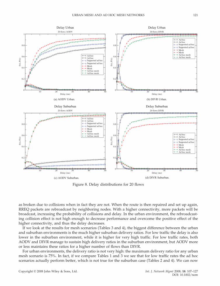
If we consider Figure 7(c) we can see that the delay for AODV (suburban) especially for the pure ad hoc case is signifi cantly higher than for any of the scenarios and environments for fi ve bidirectional fl ows. A look at Table 2 reveals that the average delay for this case is 16.7 ms. For the AODV urban ad hoc case (see Table 1) the delay is 6.2 ms. With a higher traffi c load (see Figure 8 and Tables 1 and 2) the effect is much more severe, with a delays of 195 ms and 640 ms for 25 AODV urban and suburban fl ows, respectively.
What we see here is the effect of the environment itself: how the height of the buildings affects the signal path and the performance. In a city environment, building walls completely block the signal from one parallel street to another, while in the simulated suburban environment the signal is not completely

120 A. N. PLYMOTH, U. KÖRNER AND P. JOHANSSON
Copyright © 2008 John Wiley & Sons, Ltd. Int. J. Network Mgmt 2008; 18: 107–127 DOI: 10.1002/nem
5 10 15 20 25Delay (ms)
0
0.2
0.4
0.6
0.8
1
f(x)
, F(x
)
Ad hocAd hocSupported ad hocSupported ad hocMeshMeshAd hoc meshAd hoc mesh
Delay Urban5 flows AODV
5 10 15 20 25Delay (ms)
0
0.2
0.4
0.6
0.8
1
f(x)
, F(x
)
Ad hocAd hocSupported ad hocSupported ad hocMeshMeshAd hoc meshAd hoc mesh
Delay Urban5 flows DIVR
5 10 15 20 25Delay (ms)
0
0.2
0.4
0.6
0.8
1
f(x)
, F(x
)
Ad hocAd hocSupported ad hocSupported ad hocMeshMeshAd hoc meshAd hoc mesh
Delay Suburban5 flows AODV
5 10 15 20 25Delay (ms)
0
0.2
0.4
0.6
0.8
1f(
x), F
(x)
Ad hocAd hocSupported ad hocSupported ad hocMeshMeshAd hoc meshAd hoc mesh
Delay Suburban5 flows DIVR
(a) AODV Urban. (b) DIVR Urban.
(c) AODV Suburban. (d) DIVR Suburban.
Figure 7. Delay distributions for fi ve fl ows
blocked but affected by multi-path fading. The main difference this has on the MAC layer is how carrier sensing and the hidden terminal are affected. In the suburban environment carrier sensing is possible across a block, but not in the urban environment. In the suburban environment, RTS and CTS packets will protect a 802.11 transmission from parallel transmitters, which increases the time it takes for a packet to access the channel. But since some links now experience non-line-of-sight multi-path propagation, fewer packets will also be delivered on average.
For the supported ad hoc scenarios (see Tables 1 and 2), where a relay mesh node is placed at each intersection the delay increases for low-AODV traffi c in the urban environment, while it decreases for the suburban environment. An important factor here is the connectivity and medium contention on the routes. In the urban environment, the best path across a few blocks will always pass through a relay point, which increases the contention for those nodes and therefore the delay. In the suburban environment they increase the connectivity of the network, but not all routes necessarily pass through them, resulting in a lower delay. With very high traffi c it is more complicated. Now links, or routes, may be reported
URBAN MESH AND AD HOC MESH NETWORKS 121
Copyright © 2008 John Wiley & Sons, Ltd. Int. J. Network Mgmt 2008; 18: 107–127 DOI: 10.1002/nem
10 20 30 40 50Delay (ms)
0
0.2
0.4
0.6
0.8
1
f(x)
, F(x
)
Ad hocAd hocSupported ad hocSupported ad hocMeshMeshAd hoc meshAd hoc mesh
Delay Urban20 flows AODV
10 20 30 40 50Delay (ms)
0
0.2
0.4
0.6
0.8
1
f(x)
, F(x
)
Ad hocAd hocSupported ad hocSupported ad hocMeshMeshAd hoc meshAd hoc mesh
Delay Urban20 flows DIVR
10 20 30 40 50Delay (ms)
0
0.2
0.4
0.6
0.8
1
f(x)
, F(x
)
Ad hocAd hocSupported ad hocSupported ad hocMeshMeshAd hoc meshAd hoc mesh
Delay Suburban20 flows AODV
10 20 30 40 50Delay (ms)
0
0.2
0.4
0.6
0.8
1f(
x), F
(x)
Ad hocAd hocSupported ad hocSupported ad hocMeshMeshAd hoc meshAd hoc mesh
Delay Suburban20 flows DIVR
(a) AODV Urban. (b) DIVR Urban.
(c) AODV Suburban. (d) DIVR Suburban.
Figure 8. Delay distributions for 20 fl ows
as broken due to collisions when in fact they are not. When the route is then repaired and set up again, RREQ packets are rebroadcast by neighboring nodes. With a higher connectivity, more packets will be broadcast, increasing the probability of collisions and delay. In the urban environment, the rebroadcast-ing collision effect is not high enough to decrease performance and overcome the positive effect of the higher connectivity, and thus the delay decreases.
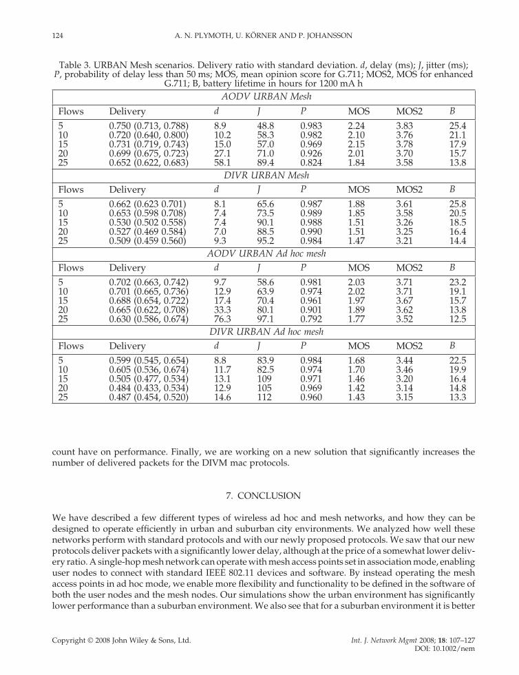
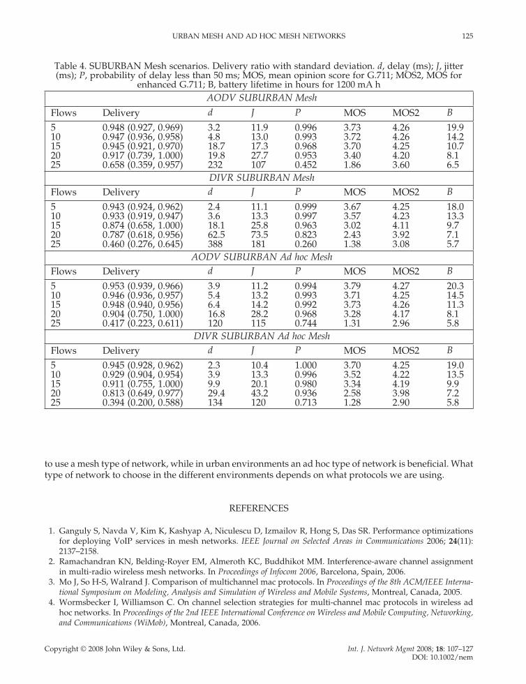
If we look at the results for mesh scenarios (Tables 3 and 4), the biggest difference between the urban and suburban environments is the much higher suburban delivery ratios. For low traffi c the delay is also lower in the suburban environment, while it is higher for very high traffi c. For low traffi c rates, both AODV and DIVR manage to sustain high delivery ratios in the suburban environment, but AODV more or less maintains these ratios for a higher number of fl ows than DIVR.
For urban environments, the delivery ratio is not very high: the maximum delivery ratio for any urban mesh scenario is 75%. In fact, if we compare Tables 1 and 3 we see that for low traffi c rates the ad hoc scenarios actually perform better, which is not true for the suburban case (Tables 2 and 4). We can now

122 A. N. PLYMOTH, U. KÖRNER AND P. JOHANSSON
Copyright © 2008 John Wiley & Sons, Ltd. Int. J. Network Mgmt 2008; 18: 107–127 DOI: 10.1002/nem
also take a look at the different mean opinion scores. In order to have at least some form of acceptable VOIP experience in an urban environment, the enhanced G.711 codec should be used. We can also make the interesting conclusion that for urban environments it is actually better to use ad hoc technologies, with the supported ad hoc network performing slightly better. If we also look at the battery lifetimes we see that the lifetimes are signifi cantly longer for the ad hoc scenarios. This is an interesting and somewhat unexpected result. Even though the mesh network operates on separate channels than the user nodes, we do not really gain anything by using their extra interfaces in a harsh urban environment. With a dif-ferent mesh confi guration, and by using more interfaces at each MP, or a different physical layer with a higher capacity, this will probably change. But for this confi guration, with the same physical layer on both user nodes and mesh nodes, we cannot see any signifi cant gain for urban environments. We leave it for future work to study the needed capacity, and the various dependent factors, for a mesh network to outperform an ad hoc network in an urban environment.
Continuing to look at battery lifetimes, we see that DIVR achieves longer lifetimes in the ad hoc sce-narios also for the suburban case. For AODV this is true for the ad hoc mesh but not for the single-hop mesh network.
Table 1. URBAN ad hoc scenarios. Delivery ratio with standard deviation. d, delay (ms); J, jitter (ms); P, probability of delay less than 50 ms; MOS, mean opinion score for G.711; MOS for enhanced
G.711, MOS2; B, battery lifetime in hours for 1200 mA hAODV URBAN ad hoc
Flows Delivery d J P MOS MOS2 B
5 0.809 (0.772, 0.846) 6.18 35.6 0.987 2.56 3.97 10710 0.784 (0.780, 0.788) 14.2 44.1 0.965 2.41 3.91 85.515 0.705 (0.671, 0.738) 40.1 70.7 0.891 2.04 3.72 66.820 0.564 (0.493, 0.634) 89.3 126 0.758 1.59 3.35 39.225 0.378 (0.314, 0.442) 195 216 0.545 1.00 2.13 35.9
DIVR URBAN ad hocFlows Delivery d J P MOS MOS2 B
5 0.676 (0.634, 0.717) 1.98 48.6 0.999 1.93 3.64 46.010 0.658 (0.625, 0.692) 2.11 52.2 0.998 1.87 3.60 35.015 0.631 (0.589, 0.674) 2.25 59.2 0.998 1.78 3.53 27.820 0.611 (0.580, 0.642) 2.13 65.1 0.998 1.72 3.48 24.625 0.586 (0.520, 0.653) 2.70 68.5 0.998 1.65 3.41 21.9
AODV URBAN supported ad hocFlows Delivery d J P MOS MOS2 B
5 0.382 (0.758, 0.907) 12.3 38.4 0.696 2.71 4.02 58.210 0.791 (0.760, 0.821) 20.1 51.0 0.947 2.45 3.93 26.315 0.750 (0.679, 0.821) 27.2 64.9 0.928 2.23 3.83 18.620 0.609 (0.579, 0.639) 63.7 115 0.828 1.71 3.47 12.525 0.543 (0.524, 0.562) 100 146 0.719 1.54 3.30 10.3
DIVR URBAN supported ad hocFlows Delivery d J P MOS MOS2 B
5 0.789 (0.743, 0.835) 1.6 25.9 1.000 2.44 3.92 47.010 0.712 (0.643, 0.780) 2.1 34.6 0.999 2.07 3.73 33.615 0.716 (0.629, 0.802) 2.0 42.4 0.999 2.08 3.74 27.420 0.695 (0.662, 0.729) 2.0 39.2 1.000 2.00 3.69 22.725 0.615 (0.512, 0.719) 2.1 51.9 1.000 1.73 3.49 21.0

URBAN MESH AND AD HOC MESH NETWORKS 123
Copyright © 2008 John Wiley & Sons, Ltd. Int. J. Network Mgmt 2008; 18: 107–127 DOI: 10.1002/nem
So, when looking at all the tables, we can see that the best VOIP MOS performance is for suburban mesh scenarios. If we limit the number of fl ows to 20, we can still achieve very high VOIP performance by using an ad hoc mesh topology instead of using a single-hop mesh. We can do this by maintaining the same battery lifetime, and with a cheaper infrastructure.
The MOS VOIP performance in the urban scenarios are always a bit lower than for suburban. With the consideration of the higher lifetime, in combination with comparable MOS performance, it seems better to use a supported ad hoc network for urban environments.
In conclusion, we can say that the type protocol that is optimal for a certain situation depends on the environment, the type of network and the amount of traffi c.
6. FUTURE WORK
For future work we will be considering other routing protocols, such as OLSR for routing within the mesh and the ad hoc networks. We would also like to study the effect other routing metrics besides hop
Table 2. SUBURBAN ad hoc scenarios. Delivery ratio with standard deviation. d, delay (ms); J, jitter (ms); P, probability of delay less than 50 ms; MOS, mean opinion score for G.711; MOS2, MOS for
enhanced G.711; B, battery lifetime in hours for 1200 mA h
AODV SUBURBAN Ad hocFlows Delivery d J P MOS MOS2 B
10 0.532 (0.495, 0.570) 122 140 0.646 1.45 3.27 9.015 0.263 (0.244, 0.283) 433 289 0.248 1.00 2.57 7.820 0.235 (0.227, 0.242) 583 325 0.171 1.00 2.49 7.625 0.210 (0.206, 0.215) 640 346 0.133 1.00 2.44 7.5
DIVR SUBURBAN Ad hocFlows Delivery d J P MOS MOS2 B
5 0.543 (0.473, 0.613) 1.7 96.5 0.999 1.54 3.30 49.610 0.539 (0.484, 0.594) 1.9 91.4 0.999 1.53 3.29 35.115 0.501 (0.468, 0.534) 2.1 104 0.999 1.45 3.19 27.320 0.497 (0.448, 0.547) 2.2 108 0.999 1.45 3.18 22.825 0.484 (0.472, 0.495) 2.3 110 0.999 1.42 3.14 20.6
AODV SUBURBAN Supported ad hocFlows Delivery d J P MOS MOS2 B
5 0.908 (0.890, 0.926) 5.4 19.3 0.990 3.32 4.18 31.910 0.911 (0.897, 0.925) 7.7 21.4 0.989 3.34 4.19 15.515 0.709 (0.589, 0.830) 218 110 0.582 1.57 3.73 7.520 0.393 (0.373, 0.413) 764 234 0.077 1.00 2.90 6.425 0.340 (0.328, 0.351) 815 243 0.048 1.00 2.76 6.4
DIVR SUBURBAN Supported ad hocFlows Delivery d J P MOS MOS2 B
5 0.832 (0.802, 0.862) 1.6 21.7 1.000 2.71 4.02 57.510 0.789 (0.742, 0.853) 1.7 32.7 0.999 2.49 3.94 37.715 0.808 (0.762, 0.854) 1.7 30.4 1.000 2.55 3.97 29.220 0.799 (0.767, 0.831) 1.8 35.9 1.000 2.50 3.95 23.525 0.739 (0.715, 0.763) 2.0 43.9 1.000 2.18 3.80 20.7
124 A. N. PLYMOTH, U. KÖRNER AND P. JOHANSSON
Copyright © 2008 John Wiley & Sons, Ltd. Int. J. Network Mgmt 2008; 18: 107–127 DOI: 10.1002/nem
count have on performance. Finally, we are working on a new solution that signifi cantly increases the number of delivered packets for the DIVM mac protocols.
7. CONCLUSION
We have described a few different types of wireless ad hoc and mesh networks, and how they can be designed to operate effi ciently in urban and suburban city environments. We analyzed how well these networks perform with standard protocols and with our newly proposed protocols. We saw that our new protocols deliver packets with a signifi cantly lower delay, although at the price of a somewhat lower deliv-ery ratio. A single-hop mesh network can operate with mesh access points set in association mode, enabling user nodes to connect with standard IEEE 802.11 devices and software. By instead operating the mesh access points in ad hoc mode, we enable more fl exibility and functionality to be defi ned in the software of both the user nodes and the mesh nodes. Our simulations show the urban environment has signifi cantly lower performance than a suburban environment. We also see that for a suburban environment it is better
Table 3. URBAN Mesh scenarios. Delivery ratio with standard deviation. d, delay (ms); J, jitter (ms); P, probability of delay less than 50 ms; MOS, mean opinion score for G.711; MOS2, MOS for enhanced
G.711; B, battery lifetime in hours for 1200 mA hAODV URBAN Mesh
Flows Delivery d J P MOS MOS2 B
5 0.750 (0.713, 0.788) 8.9 48.8 0.983 2.24 3.83 25.410 0.720 (0.640, 0.800) 10.2 58.3 0.982 2.10 3.76 21.115 0.731 (0.719, 0.743) 15.0 57.0 0.969 2.15 3.78 17.920 0.699 (0.675, 0.723) 27.1 71.0 0.926 2.01 3.70 15.725 0.652 (0.622, 0.683) 58.1 89.4 0.824 1.84 3.58 13.8
DIVR URBAN MeshFlows Delivery d J P MOS MOS2 B
5 0.662 (0.623 0.701) 8.1 65.6 0.987 1.88 3.61 25.810 0.653 (0.598 0.708) 7.4 73.5 0.989 1.85 3.58 20.515 0.530 (0.502 0.558) 7.4 90.1 0.988 1.51 3.26 18.520 0.527 (0.469 0.584) 7.0 88.5 0.990 1.51 3.25 16.425 0.509 (0.459 0.560) 9.3 95.2 0.984 1.47 3.21 14.4
AODV URBAN Ad hoc meshFlows Delivery d J P MOS MOS2 B
5 0.702 (0.663, 0.742) 9.7 58.6 0.981 2.03 3.71 23.210 0.701 (0.665, 0.736) 12.9 63.9 0.974 2.02 3.71 19.115 0.688 (0.654, 0.722) 17.4 70.4 0.961 1.97 3.67 15.720 0.665 (0.622, 0.708) 33.3 80.1 0.901 1.89 3.62 13.825 0.630 (0.586, 0.674) 76.3 97.1 0.792 1.77 3.52 12.5
DIVR URBAN Ad hoc meshFlows Delivery d J P MOS MOS2 B
5 0.599 (0.545, 0.654) 8.8 83.9 0.984 1.68 3.44 22.510 0.605 (0.536, 0.674) 11.7 82.5 0.974 1.70 3.46 19.915 0.505 (0.477, 0.534) 13.1 109 0.971 1.46 3.20 16.420 0.484 (0.433, 0.534) 12.9 105 0.969 1.42 3.14 14.825 0.487 (0.454, 0.520) 14.6 112 0.960 1.43 3.15 13.3
URBAN MESH AND AD HOC MESH NETWORKS 125
Copyright © 2008 John Wiley & Sons, Ltd. Int. J. Network Mgmt 2008; 18: 107–127 DOI: 10.1002/nem
to use a mesh type of network, while in urban environments an ad hoc type of network is benefi cial. What type of network to choose in the different environments depends on what protocols we are using.
REFERENCES
1. Ganguly S, Navda V, Kim K, Kashyap A, Niculescu D, Izmailov R, Hong S, Das SR. Performance optimizations for deploying VoIP services in mesh networks. IEEE Journal on Selected Areas in Communications 2006; 24(11): 2137–2158.
2. Ramachandran KN, Belding-Royer EM, Almeroth KC, Buddhikot MM. Interference-aware channel assignment in multi-radio wireless mesh networks. In Proceedings of Infocom 2006, Barcelona, Spain, 2006.
3. Mo J, So H-S, Walrand J. Comparison of multichannel mac protocols. In Proceedings of the 8th ACM/IEEE Interna-tional Symposium on Modeling, Analysis and Simulation of Wireless and Mobile Systems, Montreal, Canada, 2005.
4. Wormsbecker I, Williamson C. On channel selection strategies for multi-channel mac protocols in wireless ad hoc networks. In Proceedings of the 2nd IEEE International Conference on Wireless and Mobile Computing, Networking, and Communications (WiMob), Montreal, Canada, 2006.
Table 4. SUBURBAN Mesh scenarios. Delivery ratio with standard deviation. d, delay (ms); J, jitter (ms); P, probability of delay less than 50 ms; MOS, mean opinion score for G.711; MOS2, MOS for
enhanced G.711; B, battery lifetime in hours for 1200 mA hAODV SUBURBAN Mesh
Flows Delivery d J P MOS MOS2 B
5 0.948 (0.927, 0.969) 3.2 11.9 0.996 3.73 4.26 19.910 0.947 (0.936, 0.958) 4.8 13.0 0.993 3.72 4.26 14.215 0.945 (0.921, 0.970) 18.7 17.3 0.968 3.70 4.25 10.720 0.917 (0.739, 1.000) 19.8 27.7 0.953 3.40 4.20 8.125 0.658 (0.359, 0.957) 232 107 0.452 1.86 3.60 6.5
DIVR SUBURBAN MeshFlows Delivery d J P MOS MOS2 B
5 0.943 (0.924, 0.962) 2.4 11.1 0.999 3.67 4.25 18.010 0.933 (0.919, 0.947) 3.6 13.3 0.997 3.57 4.23 13.315 0.874 (0.658, 1.000) 18.1 25.8 0.963 3.02 4.11 9.720 0.787 (0.618, 0.956) 62.5 73.5 0.823 2.43 3.92 7.125 0.460 (0.276, 0.645) 388 181 0.260 1.38 3.08 5.7
AODV SUBURBAN Ad hoc MeshFlows Delivery d J P MOS MOS2 B
5 0.953 (0.939, 0.966) 3.9 11.2 0.994 3.79 4.27 20.310 0.946 (0.936, 0.957) 5.4 13.2 0.993 3.71 4.25 14.515 0.948 (0.940, 0.956) 6.4 14.2 0.992 3.73 4.26 11.320 0.904 (0.750, 1.000) 16.8 28.2 0.968 3.28 4.17 8.125 0.417 (0.223, 0.611) 120 115 0.744 1.31 2.96 5.8
DIVR SUBURBAN Ad hoc MeshFlows Delivery d J P MOS MOS2 B
5 0.945 (0.928, 0.962) 2.3 10.4 1.000 3.70 4.25 19.010 0.929 (0.904, 0.954) 3.9 13.3 0.996 3.52 4.22 13.515 0.911 (0.755, 1.000) 9.9 20.1 0.980 3.34 4.19 9.920 0.813 (0.649, 0.977) 29.4 43.2 0.936 2.58 3.98 7.225 0.394 (0.200, 0.588) 134 120 0.713 1.28 2.90 5.8

126 A. N. PLYMOTH, U. KÖRNER AND P. JOHANSSON
Copyright © 2008 John Wiley & Sons, Ltd. Int. J. Network Mgmt 2008; 18: 107–127 DOI: 10.1002/nem
5. Zheng D, Zhang J. 2006. Protocol design and performance analysis of frequency-agile multi-channel medium access control. IEEE Transactions on Wireless Communications 2006; 5(10): 2887–2895.
6. Tang T, Mandke K, Chae C-B, Heath RW Jr, Nettles S. Multichannel feedback in OFDM ad hoc networks. In Proceedings of the International Workshop on Wireless Ad-hoc Networks, New York, 2006.
7. Jain N, Das S, Nasipuri A. A multichannel mac protocol with receiver-based channel selection for multihop wireless networks. In Proceedings of the 9th International Conference on Computer Communications and Networks (IC3N), Phoenix, AZ, 2001.
8. Nasipuri A, Mondhe J. Multi-channel mac with dynamic channel selection for ad hoc networks. Technical Report, January 2004. http://www.ece.uncc.edu/~anasipur/publications.html [30 November 2007]
9. Patel J, Luo H, Gupta I. A cross-layer architecture to exploit multi-channel diversity with a single transceiver. In Proceedings of Infocom 2007, Anchorage, AK (to appear).
10. Larsson P. Selection diversity forwarding in a multihop packet radio network with fading channel and capture. ACM SIGMOBILE Mobile Computing and Communication Review 2001; 5(4): 47–54.
11. Larsson P, Johansson N. Multiuser diversity forwarding in multihop packet radio networks. In Proceedings of the 2005 IEEE Wireless Communications and Networking Conference, 2005, Vol. 4; 2188–2194.
12. Nilsson A, Johansson P, Körner U. Cross layer routing and medium access control with channel dependant for-warding in wireless ad hoc networks. In Wireless Systems and Mobility in Next Generation Internet. Lecture Notes in Computer Science, Vol. 4396 Springer: Berlin, 2007; 73–86.
13. Tope M, McEachen J, Kinney A. Ad-hoc network routing using co-operative diversity. In Proceedings of the 20th International Conference on Advanced Information Networking and Applications (AINA’06), Vol. 1, 2006; 55–60.
14. Jain S, Das SR. Exploiting path diversity in the link layer in wireless ad hoc networks. In Proceedings of the 6th IEEE WoWMoM Symposium, Taormina, Italy, 2005.
15. Wang J, Zhai H, Fang Y, Yuang MC. Opportunistic media access control and rate adaptation for wireless ad hoc networks. In Proceedings of the IEEE Communications Conference (ICC’04), Paris, France, 2004.
16. Park M, Andrews J, Nettles S. Wireless channel-aware ad hoc cross-layer protocol with multi-route path selection diversity. In Proceedings of the IEEE Vehicular Technology Conference (VTC-03-Fall), Orlando, FL, 2003.
17. Souryal M, Moayeri N. Channel-adaptive relaying in mobile ad hoc networks with fading. In Proceedings of the IEEE Conference on Sensor and Ad Hoc Communications and Networks (SECON), Santa Clara, CA, 2005; 142–152.
18. Liu J, Annamalai A. Channel-aware routing protocol for ad hoc networks: Generalized multiple-route path selec-tion diversity. In Proceedings of the IEEE Vehicular Technology Conference (VTC-05-Fall), 2005, Dallas, TX.
19. Ai J, Abouzeid A, Ye Z. Cross-layer optimal decision policies for spatial diversity forwarding in wireless ad hoc networks. In Proceedings of Third IEEE International Conference on Mobile Ad-hoc and Sensor Systems (MASS), Vancouver, Canada, 2006.
20. Wu S, Lin C, Tseng Y, Sheu J. A new multi-channel mac protocol with on- demand channel assignment for multi-hop mobile ad hoc networks. In Proceedings of the 2000 International Symposium on Parallel Architectures, Algorithms and Networks (ISPAN ’00), Dallas, TX, 2000.
21. Scalable Networks. Qualnet Network Simulator, Version 4.0, 2006.22. Cisco. Cisco Aironet 802.11a/b/g Wireless CardBus Adapter, 2007. http://www.cisco.com/en/US/products/hw/
wireless/ps4555/products_data_sheet09186a00801ebc29.html. [20 November 2007]23. G.711, I.-T. R. Pulse Code Modulation (PCM) of Voice Frequencies. International Telecommunications Union: Geneva,
1988.24. G.107, I.-T. R. The E-Model: A Computational Model for Use in Transmission Planning. International Telecommunica-
tions Union: Geneva, 2003.25. 802.20. MBWA Call for Contributions for Evaluation Criteria for VoIP Application, MOS-VOIPC802.20-05-51. IEEE
802.20 Working Group on Mobile Broadband Wireless Access. Institute of Electrical and Electronics Engineers: New York, 2005.
26. GIPS. Enhanced G.711 with GIPS NetEQ, 2007. Global IP Solutions. http://www.gipscorp.com/fi les/english/datasheets/EG711.pdf [5 November 2007].

URBAN MESH AND AD HOC MESH NETWORKS 127
Copyright © 2008 John Wiley & Sons, Ltd. Int. J. Network Mgmt 2008; 18: 107–127 DOI: 10.1002/nem
AUTHORS’ BIOGRAPHIES
Anders Nilsson Plymoth (PhD Information Technology 2007, Technical Licentiate Communication Systems 2005, Master of Science EE 2001, all from Lund University) just fi nished his PhD on Wireless Muli Hop Networks at Lund University and are now joining Calit2 (California Institute for Telecommunications and Information Technology, at University of California, San Diego) as a post doctoral researcher working on Radio Aware Mesh Networking. His research interests include wireless multi-access and multi-hop radio architecture and protocol development as well as performance modeling and evaluation of wireless systems.
Ulf Körner is currently a Professor and holds the chair in Communications Systems at Lund University. He has spent three sabbaticals at North Carolina State University, Raleigh, NC, USA in 1986, 1987 and 1992 respectively. From 1995 to 1998 he was the Dean of Electrical Engineering and Computer Engineering at Lund University. His areas of research interests are communication network architectures and protocols, performance modelling and evalua-tion. During the last fi ve year his research has been focused on wireless systems, especially on Ad Hoc networking, on WLAN technologies and on ‘Beyond 3G technologies’. He is a member of Euro-FGI (Euro—Future Generation Internet), which is one of the Network of Excellences in Europe. Dr. Körner is the author of several books, serves in several journal editor boards and has a publication list of about 100 papers published in journals and at conferences with peer reviews.
Per Johansson (M.Sc. EE, −91, Tecnical Licentiate. EE −98, Lund Institute of Technology, Lund University) is a Prin-cipal Development Engineer at Calit2 (California Institute for Telecommunications and Information Technology, at University of California, San Diego) focusing on wireless network research. Formerly, he held a Senior Research posi-tion at Ericsson Corporate Research, and brings with him 15 years of telecommunications research experience. His expertice stretches from traffi c management and performance analysis of data- and telecommunications networks, to wireless multi-access and multi-hop radio networking technologies.