upgrades of the tracker and trigger of the cms experiment...
TRANSCRIPT

25 October 2016
1
University of Bristol Brunel University London Imperial College London Rutherford Appleton Laboratory
Upgrades of the Tracker and Trigger of the CMS experiment at the CERN LHC
1 Executive Summary .................................................................................................................... 32. Project history and recent developments ................................................................................... 3
2.1 LHC operations and progress ......................................................................................... 32.2 CMS planning ................................................................................................................. 52.3 UK adaptation to CMS planning ..................................................................................... 6
3. Work Package 1: Management .................................................................................................. 84. Work Package 2: Outer Tracker Readout .................................................................................. 9
4.1 Objectives ....................................................................................................................... 94.2 Progress ......................................................................................................................... 94.3 Test plans ..................................................................................................................... 114.4 Staff on project .............................................................................................................. 124.5 Expenditure ................................................................................................................... 124.6 Deliverables .................................................................................................................. 13
5. Work Package 3: Level-1 Trigger ............................................................................................. 145.1 Objectives ..................................................................................................................... 145.2 Progress to date ........................................................................................................... 145.2.1 MP7 production summary ............................................................................................. 145.2.2 Next generation hardware development ....................................................................... 165.3 Overview of CMS plans ................................................................................................ 165.4 Staff on project .............................................................................................................. 175.5 Expenditure ................................................................................................................... 175.6 Deliverables .................................................................................................................. 17
6. Work Package 4: High Granularity Calorimeter ........................................................................ 196.1 Objectives ..................................................................................................................... 196.2 Progress to date ........................................................................................................... 196.3 Overview of CMS plans ................................................................................................ 216.4 Staff on project .............................................................................................................. 216.5 Expenditure ................................................................................................................... 216.6 Deliverables .................................................................................................................. 21
7. Work Package 5: L1 track finder .............................................................................................. 237.1 Objectives ..................................................................................................................... 237.2 Progress to date ........................................................................................................... 237.3 Overview of CMS plans ................................................................................................ 257.4 Staff on project .............................................................................................................. 257.5 Expenditure ................................................................................................................... 257.6 Deliverables .................................................................................................................. 25
8 Risk register .............................................................................................................................. 289 Finances ................................................................................................................................... 29
9.1 Working Allowance ....................................................................................................... 3010 Gantt charts .............................................................................................................................. 3111 Milestones ................................................................................................................................ 32

25 October 2016
2
12 Glossary ................................................................................................................................... 33

25 October 2016
3
1 Executive Summary The new project started in April 2013; it continues work on the tracker and trigger begun in the
previous R&D project. For the Phase I upgrade of the L1 calorimeter trigger, this has been a construction project.
In the last six months there has been further progress with the UK activities: • The final CBC design was completed in July and is currently in manufacture in a shared wafer
run. Deliveries are due within the next few weeks. • Preparations for testing the CBC3 are well underway, making use of the FC7 for DAQ. • The upgraded Level-1 trigger has been running smoothly during 2016, with excellent results. • Progress has continued with electronics design for the proposed High Granularity Calorimeter,
which is largely funded by a ERC grant at Imperial, with support from an STFC PRD post. • Substantial progress has been made with the demonstrator of the Time Multiplexed Trigger
architecture for the L1 track-finder of the future track-trigger. A CMS committee is due to review its status formally in December.
In September Costas Foudas (Ioaninna, and sometime previously Imperial College) was succeeded as Project Manager for the L1 trigger by Alex Tapper of Imperial College. Sudan Paramesvaran (Bristol) was appointed as a CMS Run Coordinator, which is a demanding role task he started in mid-2016, partly as a consequence of his very effective coordination work in the UK L1 trigger upgrade.
2. Project history and recent developments The LHC upgrade is proposed to take place in two main stages, with an increase in luminosity
reaching ~2 x 1034 cm-2s-1 a couple of years after 2015 in LHC Run II, then after a two to three year shutdown from 2023 in LS3, to 5 x 1034 cm-2s-1 levelled luminosity, denoted as Phase II at the High Luminosity (HL)-LHC. A total of 3000 fb-1 in integrated luminosity over about a decade is the goal. This should lead to a typical pileup of 140 events/BX but in view of the possibility to increase the luminosity even higher, or accommodate fluctuations without much degradation in performance, CMS aims to be operable at up to 200 events/BX corresponding to 7.5 x 1034 cm-2s-1 levelled luminosity.
The current phase of the project began on 1 April 2013. The technical work packages are WP2 for Phase II outer tracker readout R&D, WP3 for Phase I calorimeter trigger construction, now complete, and R&D aimed at Phase II, WP4 on the high granularity forward calorimeter project and WP5 on L1 track-finding.
2.1 LHC operations and progress
Over the past six months, CMS has been working intensely on: • Operating the experiment and taking data at 13 TeV under increasing luminosity conditions; • Completing the programme of Phase I detector upgrades; with the L1 trigger complete, the
major one outstanding is the new pixel detector to be installed in the Extended Year End Technical Stop (EYETS) at the end of this year;
• Beginning the preparation of Technical Design Reports for the Phase II upgrade, for the HL-LHC.
The LHC machine has performed exceptionally well this year after commissioning, at a centre of mass energy of 13 TeV with 25 ns beams. Fig. 2.1 shows the status in September.
CMS has been able to collect high quality data throughout the 2016 run, with efficiencies well above 90%. By mid-October, CMS had recorded 32.6 fb-1 of the 35.5 fb-1 delivered by the LHC,
also well beyond the target for the machine. All components of CMS have been operating smoothly.

25 October 2016
4
Fig. 2.1: LHC luminosity status in mid-September. The dashed curve labelled “Projection” represents the provisional plan early in the year.
The major concern last year was the magnet, where there were repeated problems with the
cryogenic system. The maintenance and cleaning reported last time were very successful and there have been no further problems this year.
The Phase I upgrade to the Level-1 trigger has provided physics triggers since May 2016. The new system has run extremely reliably and provided high quality data for CMS physics analysis, as shown at the recent ICHEP conference in Chicago. The level of reliability and quality of data from a completely new system shows the wisdom of the decision to commission it in parallel with the old system during the 2015 run.
Most recently the very impressive performance of the LHC has required an effort to adapt the Level-1 trigger configuration to the higher than expected instantaneous luminosity. After this programme the trigger should be able to run under the highest luminosity conditions the LHC will deliver in 2016. Preparations are also underway for the p-Pb run. A slightly modified configuration of the Level-1 trigger will be used for this run and there is close collaboration between the Level-1 trigger group and the physics groups who will analyse this data, to prepare for this run.
Looking towards the 2017 LHC run, several workshops are planned with the physics groups and trigger coordination to prepare for the 2017 run. Further consolidation and automation of data quality monitoring and troubleshooting will continue during the break.
The exceptional performance of the LHC in terms of peak luminosity triggered the formation of a study group to identify the present limits of CMS for the rest of the running time in 2016 and to evaluate expected limits for the coming years. The most stringent limit identified is in the readout speed and dynamic inefficiency of the present pixel detector, that becomes significant at luminosities above 1.55 1034cm-2s-1. Such a value is not foreseen in 2016, and the limit will be completely removed with the new pixel detector, planned for installation during the EYETS. The working group will also analyse potential limits at even higher luminosities in close contact with the LHC Programme Coordination, to plan data taking conditions for 2017 and 2018.
put in perspective
2016.09.21 [email protected]

25 October 2016
5
Figure 2.2: The LHC 2016 status and near future plans in mid-October.
A programme of simulations and hardware R&D for the Phase II upgrade is underway, with
several new institutes showing interest in joining the project. A group within the Level-1 trigger project is working closely with the CMS sub-detector projects to define the information that will be provided to the Level-1 trigger in this future upgrade. The project aims to release a planning document in the Autumn next year, to complement the sub-detector Technical Design Reports, reflecting the status of the design of the Phase II Level-1 trigger system.
2.2 CMS planning
CMS is pursuing an intense programme of Phase II upgrades for the HL-LHC era. The upgrade plans were documented in a Technical Proposal (TP), that presents the main motivations and features, accompanied by a Scope Document (SD) which complements the TP with additional studies, including the impact of potential scope and cost reductions on detector performance and physics reach. Progress has been made with two priorities for Phase II: the revision of the beam pipe, planned in Long Shutdown 2 (LS2) and the extension of the support facilities at LHC Point 5, Cessy.
The Technical Design Reports (TDRs) for the major projects (Tracking System, Barrel Calorimeters, Endcap Calorimeter and Muon Systems) will be submitted to the LHCC and UCG in 2017, with the first being the Tracker TDR next June. The Trigger and DAQ upgrades require shorter production times and can, therefore, take advantage of new technologies expected during this period, thus the corresponding TDRs will be submitted in 2019-2020. However, an interim document describing their baseline designs will be provided by September 2017. The infrastructure upgrades and the logistics of work during the LS3 will also be documented by the fall of 2017. For all of these projects detailed sets of milestones have been presented to the LHCC, laying out the path towards the
Schedule for Remainder of the 2016 Run
Joel Butler, RRB 43, Oct. 25, 2016 25/10/16
EYETS=Extended'Year+end'Technical'Stop'(20'vs'normal'13'weeks)'
• ''proton+proton'run'is'ending;''next'is''p+lead'run'at'√sNN'of'5'and'8'TeV'• The'original'LHC'pp'run'was'reduced'by'one'week'to'allow'the'LHC'to'
work'on'training'magnets'in'two'sectors'for'14'TeV'• The'end'of'the'winter'shutdown'has'not'changed'(pixel'schedule)'
6

25 October 2016
6
TDRs. Overall, there is good progress with prototyping and test activities that will lead to the design choices.
To meet the schedule, each upgrade project is developing a complete Work Breakdown Structure divided in two major periods, the first one leading to the completion of the design and R&D, which is marked by Engineering Design Reviews (EDR), and the second covering construction and installation of the detectors. The final agreements on funding and on construction responsibilities will follow the TDR approvals that are essential milestones of the first period.
In addition to the completion of all major design choices, the TDRs will demonstrate that the required physics performance is met, together with the technical and financial feasibility of each upgrade. Accompanying each TDR, detailed cost and schedule information, and a risk assessment will be provided to the Upgrade Cost Group, including a mitigation plan that preserves as much as possible the physics performance if the full cost profile cannot be realized. The funding model is under further development, updating the anticipated funding for each project and expected profile for each funding agency.
The Tracker project includes upgraded replacement detectors for the Outer Tracker (OT) and Pixel detectors. For the OT, market surveys have been completed for the silicon sensor hybrids, two major components of the tracker modules. Module prototyping is progressing well, and prototype ASICs with full functionality have either been submitted (CBC) or the design is being prepared (SSA and CIC). An improvement to the overall geometry, with tilted modules in the central barrel region, is being studied in simulations and may achieve some cost savings while preserving performance.
The design of the OT is optimized to provide track information to the upgraded online trigger. The OT project includes a track trigger processor to reconstruct raw detector information and form the track candidates for the trigger. Three approaches for the track trigger are under study. Demonstrator systems have been assembled for the three approaches and are currently being characterized to demonstrate that system requirements can be met, and to allow choices to be made for the final system.
The electronics of the barrel calorimeters will be replaced to accommodate the increased data flows expected at the HL-LHC. For the electromagnetic calorimeter this upgrade will allow the trigger to fully exploit the ultimate precision offered by the crystals, to measure the arrival time of particles, and therefore to discriminate, with some efficiency, photons produced in the different collisions (pileup) occurring in the same crossing of the HL-LHC beams.
The Endcap Calorimeter features a high granularity electromagnetic section using silicon sensors with a pad segmentation, and a hadronic section using the same technology followed by a less highly segmented scintillator tile section. The high granularity of this system will allow measurement of the 3D topology of energy deposits in particle showers induced by incident electrons, photons and hadrons. Prototype silicon sensors from two vendors are under study, with fabrication underway at the third vendor, and an extensive test beam program is ongoing for prototype modules. The first full functionality prototype chip (SKIROC2-CMS) is under test and will be used in test beam runs in 2017. Stainless steel has been chosen for the absorber material in the back hadronic section. Design choices for the overall structure are planned for Q4 2016.
The generation and reconstruction software for simulating the performance of the upgraded detectors is under development. Monte Carlo production is anticipated for late 2016 and early 2017 to support the performance studies for the TDRs, which will include demonstration of particle identification and physics benchmark channels.
2.3 UK adaptation to CMS planning
Since our last report, STFC requested from CMS UK an outline construction plan for the period 2019-2024, which was submitted to them in September. This explains the UK intentions in broad terms, with a cost and effort schedule and estimates of cost contributions to the CMS experiment. A review of the document is to be carried out with a meeting with the proponents in early November, shortly before the OsC meeting, followed by recommendations to Science Board in December.
25 October 2016
7
A significant input to our planning is a decision on the architecture on the L1 track-finding processing, where three alternatives, one of which is a UK time-multiplexed design, are under consideration and demonstrators are under construction.
It was agreed in late 2014 that the three groups would build demonstrators based on existing hardware to provide evidence that L1 tracking will be feasible within the available latency, with at least one of the methods; this is a milestone for the TDR. The comparison of the features and performance of the three demonstrators should also provide essential information for specifying the final implementation in CMS.
A committee composed of D. Abbaneo (chair), D. Acosta, C. Foudas, A. Marchioro, E. Perez, R. Van Berg (from ATLAS) and F. Vasey carried out a preliminary review in May. After a second review in December, the committee will produce a concise report summarizing their findings and evaluation of the projects, along with considerations and recommendations on how to develop an optimal implementation in CMS.
This is foreseen to be followed by a presentation and discussion of the next steps in the Tracker Institution Board, in early 2017. The CMS spokesperson has also recently contributed some comments on the decision process.

25 October 2016
8
3. Work Package 1: Management A reminder of the project management is included below, including some changes. G. Hall
remains PI for this project. D. Newbold has been UK CMS PI since October 2015. Since Alex Tapper became CMS L1 trigger project manager in September 2016, he has passed the
role of co-manager of WP3 to Greg Iles, who has been the main designer of most of the trigger hardware and is responsible for the maintenance and operation of the UK part of the L1 calorimeter trigger.
WP Manager Institute Role1 GHall,PI Imperial Overallmanagement,budgetaryresponsibilityand
supervisingprocurements,interfacetoCMS,toUKCMSPI.CMSManagementBoardmembertoSep2016andTrackerManagementBoardmember.
2 MRaymond Imperial OverallresponsibleforCBCspecifications,interfacetomoduledesignteam,chiptestingandmoduleevaluationandCMSplanning
MPrydderch RALTD ManagerofASICdesignteaminRAL
3 GIles Imperial BasedinCERNwithresponsibilitiesforoperationofL1calorimetertrigger.
JBrooke Bristol SupervisionofUKPhaseItriggerupgradeactivities,withATapper.PreviouslyDPGconvenorandsoftwarecoordinatorinthetriggerproject.
4 PDauncey Imperial JointlycoordinatingtheUKHGCaldevelopments,withGDavies.L1triggercoordinatorfortheHGCal.
GDavies Imperial Also,UKrepresentativeontheprovisionalHGCalIBandFB.
5 MPesaresi Imperial Coordinatingdemonstratorintegrationactivitiesandhardware/firmwarespecifications,andgeneralprojectplanning.
ITomalin RALPPD MaintainingandrunningtheMonteCarloanalysissoftware,improvingtrackingalgorithmsbasedonofflineexperienceandday-to-dayoversightofRALtracktriggeractivities.

25 October 2016
9
4. Work Package 2: Outer Tracker Readout
4.1 Objectives
• To complete the development of a readout and triggering chip suitable for the 2S-PT module, bringing the chip to a final state ready for mass production.
• To develop the hardware and software required for the large-scale production testing procedures, and to deliver tested wafers to the CMS experiment.
• To play a major role in construction, definition and evaluation of prototype modules. • To contribute to development of ancillary chips required for the 2S-PT module, and to
participate in the PS-PT module development. • To contribute to the future large-scale module production programme, and to participate in
integration and commissioning activities.
4.2 Progress to date
The CBC2 test and prototyping phase is coming to an end. It has been a very successful development with all its associated goals now achieved. The bump-bondable layout has facilitated the R&D on hybrid technologies allowing the construction of 2S modules to make good progress, and two companies (AEMTEC and Valtronic) have now successfully produced full-size 8-chip hybrids. The PT stub triggering approach and performance has been successfully demonstrated in beam tests at DESY and CERN. Hybrid work progresses, with CBC2 chips being used to investigate issues for hybrid designs for the PS system, allowing progress to continue before full-size prototypes for the PS system become available next year.
CBC3 is the 130 nm CMOS bump-bondable front end readout chip for the 2S modules in the outer silicon tracker. It was submitted for manufacture in July, in accordance with the revised schedule presented in the last OsC report, and we are expecting wafers to be delivered in the next few weeks. (We have been notified during report writing of transit to CERN.) Initial single-chip test setup preparations are well-advanced, and firmware and software are being developed for ionizing and SEU tests using an FC7 based system. The previous version of the chip, CBC2, continues to be used for hybrid and module studies in lab.
The 2S-PT module concept works on the principle of detecting signals in two closely spaced sensor layers, bringing the signals together in a single CBC chip. A high PT stub is present if a seed cluster is detected in the inner layer (closest to the beam interaction point) and a corresponding cluster is found in the upper layer, within a window of programmable width and offset. The layer separation and window width defines the PT threshold. The CBC2 chip implemented a basic logic circuit which merely produced a pulse on a single output line if a positive correlation was detected. The CBC3 will produce stub addresses and additional stub information that must be passed off-detector at high speed to contribute to the Level 1 trigger decision.
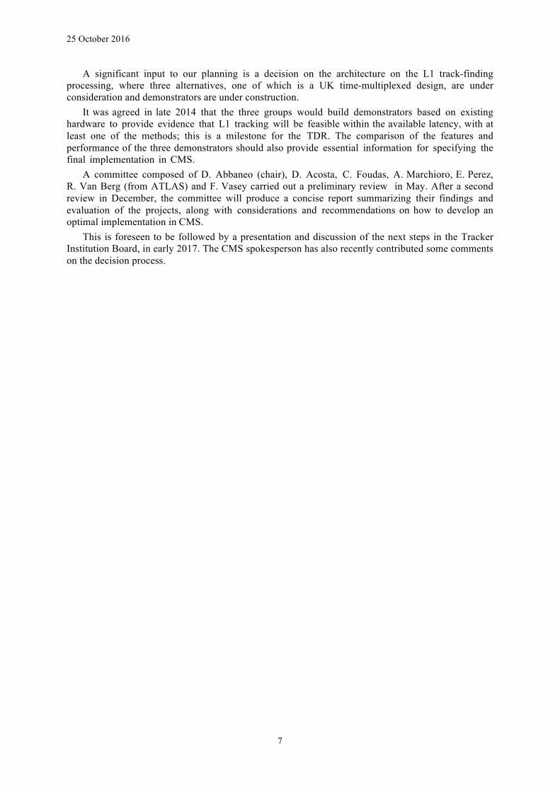
The final layout of the submitted CBC3 is shown in figure 4.1, with the main design blocks identified. A functional block diagram of the chip is shown in figure 4.2. There are many changes compared with the previous version of the chip. The front end amplifier pulse shape has been modified to achieve a shorter overall pulse shape to allow a signal to be confined to a single bunch crossing. Other modifications directly related to the front end include:
• provision to run higher currents in the input transistor to allow low noise to be achieved with longer sensor strips if necessary
• changes to bias circuits to avoid common mode effects when many channels fire • increased resolution and linearity for the global comparator threshold VCTH.
The circuit blocks implementing the digital functionality of the CBC3 have almost all been
modified compared with the previous CBC2 implementation, and new functional blocks have been designed. Half-strip resolution has been implemented in the Cluster Width Discrimination block by assigning 2 and 4 strip clusters to the mid-position between two strips, so an 8-bit cluster address is

25 October 2016
10
required. The Stub Gathering Logic block passes the 8-bit stub address of the seed cluster and an additional 5 bits of data called the bend information, which is the location of the correlating cluster in the window layer, and which carries information on the stub direction which can be useful to the off-detector track-finder. Five bits define the cluster position with full ½ strip resolution, but this level of precision is unnecessary, so the Bend Lookup Formatting block contains a programmable lookup table which reduces the 5 bits to 4 and which can be programmed differently to optimize the bend resolution in different regions of the tracker.
Fig. 4.1: Final layout of the CBC3 chip submitted for manufacture
The Stub Gathering Logic can pass up to 3 stub addresses plus associated bend information per
bunch crossing, which is more than sufficient. In the unlikely event that a fourth stub is present it will be lost, but a Stub Overflow bit will be set in the output data packet corresponding to that bunch crossing.
The Data Packet Assembly & Transmission block formats the stub data and overflow bit onto 5 differential lines at 320 Mbps, so that all triggering data is transmitted off-chip in the 25 ns bunch crossing period.
The CBC3 pipeline has been modified to improve radiation hardness and extended to twice the length of the CBC2 (512 cells) allowing a L1 trigger latency of up to 12.8 microseconds. A 32 deep buffer for triggered data awaiting readout is implemented, which provides negligible data loss for an average L1 trigger rate of up to 1 MHz. Following a trigger a Parallel-In-Serial-Out shift Register is used to transmit the unsparsified triggered data off-chip at 320 Mbps.
All off-chip data interfaces from the chip operate differentially at 320 Mbps. A 320 MHz clock is therefore required, and trigger and other fast control information is provided at 320 Mbps. The LHC clock frequency of 40 MHz is derived from a fixed pattern in the data on the fast control line, and passes through a Delay Locked Loop (DLL) circuit where a programmable delay is implemented to allow the 40 MHz clock domain to be synchronized with the particle arrival time.
25 October 2016
11
Fig. 4.2: CBC3 functional block diagram
4.3 Test plans
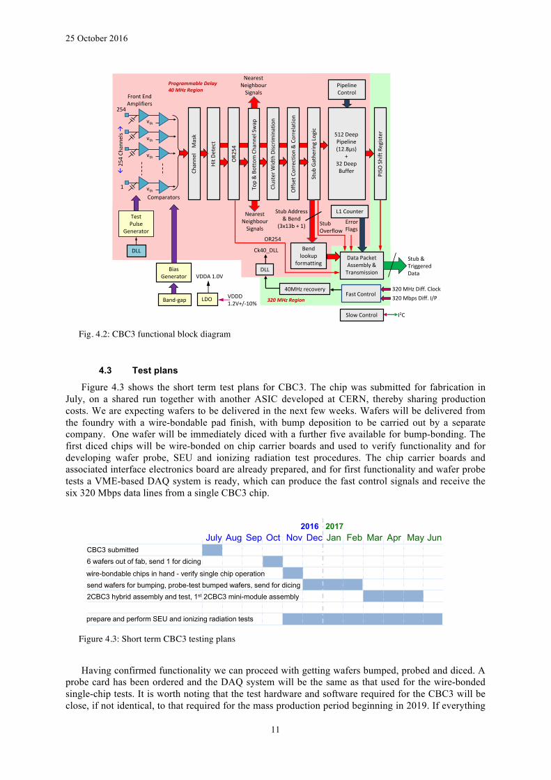
Figure 4.3 shows the short term test plans for CBC3. The chip was submitted for fabrication in July, on a shared run together with another ASIC developed at CERN, thereby sharing production costs. We are expecting wafers to be delivered in the next few weeks. Wafers will be delivered from the foundry with a wire-bondable pad finish, with bump deposition to be carried out by a separate company. One wafer will be immediately diced with a further five available for bump-bonding. The first diced chips will be wire-bonded on chip carrier boards and used to verify functionality and for developing wafer probe, SEU and ionizing radiation test procedures. The chip carrier boards and associated interface electronics board are already prepared, and for first functionality and wafer probe tests a VME-based DAQ system is ready, which can produce the fast control signals and receive the six 320 Mbps data lines from a single CBC3 chip.
Figure 4.3: Short term CBC3 testing plans
Having confirmed functionality we can proceed with getting wafers bumped, probed and diced. A
probe card has been ordered and the DAQ system will be the same as that used for the wire-bonded single-chip tests. It is worth noting that the test hardware and software required for the CBC3 will be close, if not identical, to that required for the mass production period beginning in 2019. If everything
PipelineControlFrontEnd
Amplifiers
vth
vth
vth
vth
512DeepPipeline(12.8µs)
+32DeepBuffer
TestPulse
Generator
BiasGenerator
SlowControl
OffsetCorrection&Correlatio
n
1
254
I2C
320MbpsDiff.I/P
DataPacketAssembly&Transmission
Stub&TriggeredData
VDDD1.2V+/-10%Band-gap LDO
VDDA1.0VClusterW
idthDisc
rimination
HitD
etect
PISO
ShiftRe
gister
Comparators
Stub
Gathe
ringLogic
ß25
4Ch
anne
lsà
320MHzDiff.Clock
DLL
DLL
ProgrammableDelay40MHzRegion
320MHzRegion
NearestNeighbourSignals
Bendlookup
formatting
NearestNeighbourSignals
L1CounterStubAddress&Bend
(3x13b+1)
Top&BottomChann
elSwap
Channe
lM
ask
Ck40_DLL
40MHzrecovery
OR2
54
FastControl
StubOverflow
ErrorFlags
OR254
July Aug Sep Oct Nov Dec Jan Feb Mar Apr May Jun2016 2017
CBC3 submitted6 wafers out of fab, send 1 for dicing
wire-bondable chips in hand - verify single chip operationsend wafers for bumping, probe-test bumped wafers, send for dicing2CBC3 hybrid assembly and test, 1st 2CBC3 mini-module assembly
prepare and perform SEU and ionizing radiation tests

25 October 2016
12
goes smoothly we should have bump-bondable chips in hand before the end of the first quarter of next year.
The VME DAQ system is well-suited for first tests and wafer probing, allowing quick investigations into unexpected behavior, reusing well understood and flexible hardware and software. But for future compatibility an FC7 based DAQ system is also in preparation. This can be used for the SEU and ionizing tests which we propose to carry out in the first half of next year depending on availability of sources. The firmware and software required for these tests will also be suitable for reading out CBC3 based 2S modules.
The plan for CBC3 hybrids is to follow a similar approach to the CBC2 with a small 2-chip hybrid in the first instance, which allows all functionalities to be thoroughly tested, with small sensors (full-size length but reduced number of strips), in a relatively compact and easily handled object. The 2CBC3 hybrids will be designed at CERN, and will connect electrically to an interface card which can be designed to accommodate a full-size 8-chip hybrid.
The much larger data volume generated by the CBC3 (six output data signals at 320 Mbps) places demands on the front end data acquisition. In the final system each front end hybrid houses a CIC chip which takes the data from the CBC chips, zero-suppresses and formats it for off-module transmission via an optical interface.
We have recently been informed that there will be a delay to the CIC development (which is the responsibility of the Lyon group) with a submission not expected before the middle of next year. Until the CIC becomes available an interim solution will be used, emulating the CIC functionality in the front end DAQ system. From figure 4.3 it can be seen that the hardware should be in place to allow test beam activity from the middle of next year onwards. We are discussing possible assistance from the UK, since demonstration of the CBC must ultimately include its interface to the CIC, and this should not be excessively delayed.
4.4 Staff on project
As mentioned in the previous report, Georg Auzinger joined Imperial College on 1 September as a PDRA based in CERN with the task of developing the CBC DAQ system and beam tests for 2017, collaborating closely with Kirika Uchida based at Imperial. The tests are important to allow us to sign off the design prior to the TDR.
Sarah Greenwood, who is the Imperial College electronic technician who has become expert at multi-layer digital board layout, for example of the MP7, FC7 and Ultrascale boards, will retire in March 2017 and interviews have taken place for a replacement.
Since the last OsC meeting, there have been two relevant staff changes at Bristol: Sarah Seif el Nasr joined Bristol as a project-funded PDRA on July 1st, working in WP2. She has
already made several contributions including working on the set up of a new test stand at CERN, participating in and helping coordinate the September beam test, and investigating some readout errors seen in the previous test beam.
Paolo Baesso has joined the Bristol group in a CG-funded position as an electronic engineer/physicist. This significantly enhances the available electronics design effort at Bristol, and this capability can be deployed to support tracker testing and other activities.
4.5 Expenditure
As usual much recent expenditure has continued to be on RAL TD staff, and the cost in the middle of this year was larger than expected because of pressures in completing all the design changes in time. It became clear in early 2016 that the incremental modifications to the design, partly to adapt to the overall CMS system design but also to improve a few details which were considered sub-optimal, had generated more work than anticipated, so the effort required had increased. However, the overall TD staff budget still looks sufficient. This is discussed further in the Finance section.
The major part of the CBC3 manufacturing cost (~£180k) has been invoiced to Imperial College by CERN since funds are required to be available in CERN to place the ASIC manufacturing order.

25 October 2016
13
4.6 Deliverables
The WBS for WP2 is included below. The delay to the CBC3 design and test (items in red) was discussed in the last report. WBS item 2.3 (CBC3 development and test setup preparation) is now essentially complete. The CBC3 test programme (WBS item 2.4), which was due to commence in March of this year, will now begin in the next few weeks.
The overall goal of the project is to be ready for full-scale production by the end of 2018, which requires an engineering run with the final masks in the middle of that year. Effectively that means that the suitability of the final CBC version for the application should be established by the end of 2017, which is not far away. When we know how well the CBC3 is performing we will be able to make a better assessment of the schedule for the remainder of the project, since WBS item 2.5 (CBC4 design and test) is a contingency iteration which depends on the success of the CBC3. A clear picture should be available by the time of the next OsC report.
WBS WBSL2 Start Finish Months TaskDescription2 PhaseIItrackerReadout 04/13 03/19 72 2.1 system 04/13 03/14 12 definitionoftheCBC-based2S-PTmodule
readout 2.1.1specification
definition04/13 03/14 12 regularmeetingswithCMScollaboratorsto
defineoverallsystemspecificationandinterfaces
2.2 CBC2test 04/13 03/15 24 CBC2isfinaldeliverableoftheUKupgradeR&D
2.2.1CBC2on-goingtesting 04/13 03/14 12 completethedetailedstudiesoftheCBC2chip,includingirradiationandSEUtests
2.2.2CBC22S-PTmoduleprototypestudies
04/13 03/15 24 aprogrammeofSS-PTmodulestudies,incollaborationwithCMS,includingtestbeam
2.3 CBC3 04/14 03/16 24 CBC3isspecifiedforthefinalsystem 2.3.1CBC3design 04/14 09/15 18 designperiod 2.3.2CBC3production 09/15 03/16 6 productionperiod 2.3.3testsetuppreparation 09/15 03/16
6
waferandchiptestsetuppreparation
2.4 CBC3test 03/16 03/18 24 CBC3chipandmoduletesting 2.4.1earlytests 03/16 09/16 6 chipverificationteststopriortomoduletests 2.4.2on-goingtesting 09/16 03/17 6 completecharacterization,includingirradiation
andSEUtests 2.4.3CBC32S-PTmodule
studies09/16 03/18 18 CBC3basedmodulestudiesincollaboration
withCMSinlabandtestbeam
2.5 CBC4designandtest 09/16 12/17 15 CBC4isthefinalversionofthechip,fixinganyremainingbugsfoundintheCBC3
2.5.1CBC4design 09/16 12/16 3 designperiod 2.5.2CBC4production 01/17 06/17 6 productionperiod 2.5.3testing 07/17 12/17 6
teststoverifyfullandfinalfunctionality
2.6 CBC4massproductionpreparations
01/18 12/18 12 afullwaferengineeringrunisrequiredforCBC4inpreparationformassproduction
2.6.1CBC4finalmasks 12/18 03/18 3 maskpreparationforfullwaferengineeringrun 2.6.2CBC4engineeringrun 03/18 09/18 6 productionperiod 2.6.3CBC4finalproduction
readinessverificationtests09/18 12/18 3 finalfunctionalitycheck
2.6.4procurementplanning 01/18 12/18 12 detailedfinancialplansformassproduction

25 October 2016
14
5. Work Package 3: Level-1 Trigger
5.1 Objectives
• Improvement of the current CMS calorimeter trigger in preparation for above-design-luminosity conditions.
• Provision of infrastructure to allow testing of an entirely new calorimeter trigger in parallel with the existing system.
• Design, construction and testing of a time-multiplexed hardware trigger for CMS, capable of implementing new and more selective algorithms.
• Design of a track trigger architecture for HL-LHC running, and construction of a technology demonstrator.
5.2 Progress to date
The Phase I upgrade to the Level-1 trigger has been running successfully since May 2016. There was steady improvement in algorithms and configuration to optimise data quality through the first months of the 2016 LHC run. To date the Level-1 trigger contributed to less than 10% of the small amount of collision data that CMS failed to record. In addition, only around 3% of the small amount of data recorded by CMS but later marked as bad, due to detector problems, was as a result of the Level-1 trigger. This level of reliability and high quality data from a completely new system shows the wisdom of the decision to commission it in parallel during the 2015 run in parallel with the old system.
Since the middle of the year there have been ongoing efforts to automate monitoring procedures, in order to reduce the effort that experts must provide, and for spotting potential problems promptly. For example, an automatic data quality system has been developed to compare the functioning of the hardware with a software model, so hardware malfunctions can be diagnosed quickly and fixed promptly.
Most recently the very impressive performance of the LHC has required an effort to adapt the Level-1 trigger configuration to the higher than expected instantaneous luminosity. After this programme the trigger should be able to run under the highest luminosity conditions the LHC will deliver in 2016. Preparations are also underway for the p-Pb run. A slightly modified configuration of the Level-1 trigger will be used for this run and there is close collaboration between the Level-1 trigger group and the physics groups who will analyse this data, to prepare for this run.
5.2.1 MP7 production summary
We have reviewed the outcome of the MP7 manufacture, both to put the experience in perspective now that the stressful period of installing and commissioning the Phase I trigger system is over, but also to see what guidance might be offered for the future.
All 72 MP7s, including extras for the Muon and Global triggers, had been manufactured by the last review; however, assembly and test of the cards was not then yet complete. Manufacture proved far more difficult than expected from the prototype batches. This was despite a series of initiatives to ensure smooth production (i.e. a detailed questionnaire to check whether the companies had the necessary capability and experience; test structures, and a series of quality control checks). We followed CERN procurement procedures, such as market surveys and tender rules, and benefited considerably from the support of the CERN procurement team, especially in managing the contracts with the different suppliers; this expertise would be hard to replace.
The tender process produced two companies with very similar quotes, which allowed the order to be split between them to mitigate risk. ExceptionPCB (UK) and Hapro (NO) were each given full responsibility for both aspects of production: PCB procurement and assembly of the components. To further mitigate risk, production was split into several batches, with the initial batches being small.

25 October 2016
15
ExceptionPCB is primary a PCB supplier and it outsourced component assembly to Jaltek (UK)
whereas Hapro is an assembly company and it outsourced PCB procurement to NCAB (SE) which then subcontracted PCB production to FastPrint (CN).
The primary issue was PCB production. ExceptionPCB manufactured the PCBs, but only after a significant delay. The company did not have the ideal equipment for the task, which resulted in a low yield. The company identified the primary issue and tweaked the manufacturing process to deliver the PCBs, which were then successfully assembled. A subsequent batch of PCBs was manufactured to supply Hapro, who were themselves having problems with PCB procurement. This batch had serious manufacturing flaws, unconnected to the initial manufacturing issues, that should have been detected by internal quality control processes.
Hapro had outsourced PCB production to a company that specialised in sourcing PCBs (NCAB), which then subcontracted production to FastPrint. While FastPrint manufactured one batch of PCBs successfully, subsequent batches failed and eventually the company admitted that they were unable to deliver them. We then became actively involved in the Hapro PCB procurement.
Two alternative PCB suppliers were identified in addition to ExceptionPCB, who by that time seemed able to manufacture PCBs successfully. We encouraged the use of PCBs from ExceptionPCB because their initial problems seem to have been resolved and it was an excellent opportunity for a UK manufacturer. As described above, a manufacturing flaw in the ExceptionPCB PCBs supplied to Hapro resulted in all 8 of the batch being considered unusable for production purposes. (Splitting the order into smaller batches limited the failure to 8 cards which otherwise would have been 32.) The two alternative suppliers identified by us both delivered on-time and to specification.
The final yield was 97% (or 86% if the failed pre-production batch of 8 is included). Production cost came in just below the budget estimate despite the production issues because of lower than expected quotes during the tender process. The internal quality control checks of some companies were found to be insufficient and additional checks at CERN, the PCB manufacturer and at assembly company were implemented for the later PCB productions.
In hindsight it remains difficult to avoid the situation where companies bid for work that they may not have quite the capability to deliver, particularly when we are often trying to support companies enter new markets. The original contracts contained signed statements from the companies stating their capability, experience, competence in the English language, etc. Furthermore, the original contracts also required substantial quality assurance with all parts having a unique identifier to aid fault diagnosis. The additional measures implemented in the final production include the following, but some go well beyond what might be considered reasonable for card production.
(a) An extended set of test results must be supplied with the product rather than just a
certificate of conformity. (b) Cross-checks of manufacturer results by a third party. (c) Additional “real world” stress tests of the product prior to assembly (e.g. repeatedly
subjecting the card to the thermal cycles experienced during assembly). (d) Onsite visits not just to supplier, but also subcontractor. This can be difficult when
responsibility has been delegated to the supplier (one company refused.). Onsite visits during manufacture and as much testing as possible at the company.
(e) Limit subcontractor locations to those relatively accessible.
The manufacturing issues required substantial time and effort to resolve and, although the two alternative PCB suppliers were slightly more expensive, the total project cost when staff time is included would have been lower had they been used from the start.

25 October 2016
16
5.2.2 Next generation hardware development
Looking towards the future, work has continued on a successor to the MP7 for use in the Phase II CMS upgrade. Development is taking place along two paths: the MP-Ultra - a small, low cost, form factor (PCIe) card that will allow us to validate new technologies (e.g. PCB build-up, optical engines, FPGA, etc.) and the Service card - a full size ATCA card that will allow us to test and validate the core services (e.g. embedded CPU, power, signal integrity, thermal aspects, etc.).
The MP-Ultra card has returned from manufacture and the infrastructure part has been mostly validated. (The PCB manufacture and assembly was by the UK company Jaltek, who seem to have done an excellent job.) Once testing is complete the FPGA component will be mounted and the optical interface and RAM will be tested. Testing of the card has been delayed due to a focus on the L1 Track Trigger demonstrator (WP5), but it is still on schedule.
The Service card is in layout. The design is almost complete and the objective is to submit the card for manufacture before the end of the year. The MP-Ultra can be mounted on the Service card.
5.3 Overview of CMS plans
The main focus of the Phase II trigger project, led by J. Brooke (Bristol) and R. Cavanaugh (UIC/FNAL), has been the interface between the sub-detectors and the central trigger system. These interfaces will be finalised in 2017 and documented in the sub-detector TDRs, to be published by the end of that year. Work is also proceeding on object identification algorithms that combine information from tracking, calorimeter and muon detectors, inspired by state-of-the-art offline reconstruction techniques. An interim document will be submitted to the LHCC in Q3 2017, giving an overview of the trigger architecture and algorithms, to accompany the sub-detectors TDRs. The final design will be documented in a TDR in 2019.
Completely new back-end electronics for high luminosity is essential. It is necessary to handle higher bandwidth interfaces to the front-end electronics within CMS, and to process the resulting data for delivery to the DAQ system and to extract a trigger signal. This problem materialises in several places in the upgraded CMS, including tracker, HGCal and L1 trigger. Therefore it is natural to ask if common solutions are possible. We and CERN have particularly drawn attention to this question, and it is included in our long term plan for the UK upgrade construction contributions.
We intend to build on our successful R&D accomplishments, of general purpose state-of-the-art digital electronic boards accompanied by comprehensive firmware and software, much of which has been adopted throughout CMS. We are among the most experienced developers of advanced programmable logic and high speed optical technology.
Therefore we have begun to view the Ultrascale development as a step towards common hardware, rather than targeted solely at the trigger, which was the picture at the time of the proposal in 2012. We propose its evolution towards a generic, programmable processing card with high speed optical I/O, which will then be used for applications proposed in all UK work packages. We have been in discussions with CERN and a few CMS technical experts about how this might happen, but it is still at an early stage. It has not yet evolved into a project, but should do so in 2017, once clarification of the future of the L1 track finder activity has taken place.
It is not expected that a single board will satisfy all objectives; however, adaptations into a small family of very similar boards should meet the requirements of most projects. In particular, the power system, embedded computing, crate control, optical technology and cooling system will remain unchanged or with slight modifications. They require significant design and testing effort, and the aim will be to share the load with partners at CERN and elsewhere. These parts should be interchangeable so that the base card becomes a low risk object. The infrastructure firmware and core software libraries should also be applicable to other projects and only require additional modules for covering project-specific functionality.
A possible roadmap for the future is shown below, fig. 5.1.

25 October 2016
17
Fig. 5.1: Possible roadmap for common hardware developments resulting from the present R&D.
5.4 Staff on project
As mentioned in WP4, Sarah Greenwood, who has been responsible for layout of the MP7, FC7 and Ultrascale boards at Imperial, will retire in March 2017 and interviews have taken place for a replacement.
5.5 Expenditure
Overall spending is within the budget foreseen.
5.6 Deliverables
The deliverable list is appended below. Blue font means complete. Red font is delayed. PM represents duration of the task.
L1 L2
Start Finish PM Taskdescription
3.1
Stage-1calorimetertriggerupgrade 3.1.1 Hardwaredevelopment 07/13 6 Finalisationofproductionhardwaremodule(48-
linkversion) 3.1.2 Procurementandtesting 07/13 10/13 3 Procurement,productionandacceptancetestsof
hardware 3.1.3 μTCAinfrastructure 07/13 6 CompletionofbaselineIPbus/uHAL 3.1.4 Onlinesoftwaredevelopment 04/13 10/13 6 Developmentofsystem-specificandtrigger-wide
onlinesoftware(control,monitoring,DAQ) 3.1.5 Algorithmsandofflinesoftware 04/13 04/14 12 Developmentofstage-1algorithmsand
correspondingemulatorandDQMsoftware 3.1.6 Integration 07/13 01/14 6 Integrationtestswithothertriggercomponents,
DAQ,TTC 3.1.7 Commissioning 09/14 03/15 6 Commissioningwithcosmicsandbeam 3.1.8 Support 03/15 01/16 9 Ongoingexpertsupportandoptimisationof
Stage-1system 3.2 Stage-2calorimetertrigger(TMT)upgrade 3.2.1 Hardwaredevelopment 10/13 04/14 6 Developmentandfinalisationofproduction
hardwaremodule(72-linkversion) 3.2.2 Procurementandtesting 04/14 10/14 6 Procurement,productionandacceptancetestsof
PCIe CardMP/Ultra
ATCAService
DemonstratorThermal &
Signal Integrity Demonstrator
2016
2017
2018
2019
2020
2021+
DemonstratorSystems Prototype “full”
board
Final Prototype Design
Application Designs
Building blocks
Prototype stage-1
Prototype stage-2
Pre-production

25 October 2016
18
hardware 3.2.3 Onlinesoftwaredevelopment 10/13 04/14 6 Developmentofsystem-specificandtrigger-wide
onlinesoftware(control,monitoring,DAQ) 3.2.4 Algorithmsandofflinesoftware 04/14 04/15 12 Developmentofstage-2algorithmsand
correspondingemulatorandDQMsoftware 3.2.5 Integration 04/14 10/14 6 Integrationtestswithothertriggercomponents,
DAQ,TTC 3.2.6 Commissioning 04/15 04/16 12 Commissioningwithcosmicsandbeam 3.2.7 Support 04/16 04/19 36 Ongoingexpertsupportandoptimisationof
stage-2system 3.3 Post-LS3triggerR&D 3.3.1 Designstudies 04/13 10/14 18 Simulationstudiesoftracktriggerperformance,
anddecisiononfinalconcept 3.3.2 Dataflowdesign 10/14 10/15 12 Detailedsimulation,architecturedesignand
technologychoicesfortracktrigger 3.3.3 Hardwaredevelopment 04/16 10/17 18 Developmentofnext-generationhardware
modulesforintegratedL1trigger 3.3.4 Algorithmsandofflinesoftware 10/15 04/17 18 Developmentofalgorithmsandfirmwarefor
integratedL1trigger 3.3.5 Integrationanddemonstration 10/17 10/18 12 HardwareslicetestofintegratedL1trigger 3.3.6 Finalsystemdesign 10/18 04/19 6 Productionplanningforfinalversionof
integratedL1trigger

25 October 2016
19
6. Work Package 4: High Granularity Calorimeter The HGCal project is still young, with a strong Imperial College presence. Within this R&D
project, most of the funding is provided by an ERC grant held at Imperial, supplemented by a PRD post funded by STFC, and some CG effort, hence we have not attempted to merge the WP4 financial status into the existing project reporting.
6.1 Objectives
• To play a leading role in producing the HGCal TDR at the end of 2017, both in terms of overall project management and technical aspects in the key areas listed below.
• To contribute to the design and testing of the front-end electronics ASIC for the HGCal in collaboration with the Omega/EP group in Paris.
• To develop the trigger primitive generator (TPG) and back-end readout electronics system, including algorithms, firmware and common hardware.
• To study the physics performance of the HGCal and optimise the design parameters and in addition develop the reconstruction techniques to provide the best overall performance.
6.2 Progress to date
There has been good progress across the HGCal project, including all three areas with UK involvement, namely the front-end electronics, the trigger and the simulation and performance studies.
The work on the analogue front-end electronics has proceeded along two paths. The main effort has been on developing a test system for, and thoroughly evaluating the performance of, the SKIROC2-CMS front-end ASIC designed by the Omega group; see fig. 6.1.
Fig 6.1: Example of response curves for four gain options on a SKIROC2_CMS ASIC channel. The upper two curves are low and high gain ADC measurements, while the lower two curves are similar but for time-over-threshold TDC measurements.
This was submitted for fabrication in April 2016 and will be used for the beam tests of the sensors developed for the HGCal. The tests show noise and time-of-arrival (TOA) jitter comparable to simulations, channel gain matching and stability comparable to expectations, but a smaller linear range than expected. The lower end of the measurement range of the time-over-threshold (TOT) method for digitizing large signals proved to be higher than expected, leading to a decision to evaluate the TOT circuit relative to the low-gain ADC path (rather than the high-gain path as originally intended).
Issues currently being investigated include the temperature sensitivity of the TOT circuit and the significant non-linearity of the TOA circuit. The second aspect of this work is analogue electronics design work aimed at optimising the electrical performance of the front-end. This work commenced while waiting for the SKIROC2-CMS test boards, but has been on hold since mid-July. The work so far has focused on developing a framework for optimizing front-end amplifiers of various
0 500 1000 1500 2000Input charge (fC)
0
500
1000
1500
2000
2500
3000
3500
Digi
tal o
utpu
t cod
e
LG ADCHG ADC2x TOT (high)2x TOT (low)

25 October 2016
20
architectures, but once this work is resumed (expected 2016 Q4, i.e. when the current tests have been concluded), the ambition is to investigate possible improvements to the current front-end design, such as circuit tuning for improved noise performance and ways of improving the performance for large signals.
Much of the recent work within the UK on the HGCal trigger has been focused on the creation of the raw data for the trigger primitive generator, which are produced on-detector in the front-end electronics. This is a priority as the design of these electronics will need to be frozen much earlier than the rest of the trigger generator. The occupancies and hence required bandwidths as a function of the position within the HGCal have been evaluated in several different scenarios and the effect of the front-end data processing has been quantified. These studies indicate the trigger photon resolution is likely to be limited by the readout bandwidth available, so efforts to optimize the use of the existing bandwidth are starting.
Work on the firmware for the off-detector trigger primitive generator has also made progress. The aim is not to produce “final” firmware in any sense, as the detector will not be running until ten years from now. Instead, small pieces of the most difficult steps of the proposed algorithms have been implemented, so as to estimate the resources needed for the full trigger. The current work is focused on the two-dimensional (2D) clustering which will take place within each layer as the first step of the trigger processing. For the current system, this has been found to have a very high resource usage due to the difficulty of storing all the nearest-neighbour hit information needed for clustering, given the irregular geometry of the trigger cells. This has resulted in a re-evaluation of the sensor geometry to see if a much more regular pattern of hit shapes could reduce the FPGA resources needed, fig. 6.2.
Fig. 6.2: Left: four identical sensors showing current trigger hit shapes, illustrating the irregular hit geometry both at the edges of the sensors and longer-range. Right: four sensors with different geometries, allowing a regular trigger hit pattern across the whole plane.
Recent work on simulation and reconstruction focuses on development of robust and effective clustering algorithms, leading to identification and energy measurement of electromagnetic and hadronic showers for input into particle flow algorithms for full event reconstruction. These algorithms must function in the presence of the very high levels of pileup expected at HL-LHC.
Recent highlights include: the implementation of simulation geometry including hexagonal silicon wafers, and hexagonal sensor cells within the wafers, and realistic simulation of the electronics and signal digitization; the implementation of an elegant "imaging" algorithm to form 2D clusters in each of the 40 layers of the calorimeter, see fig. 6.3, for which the algorithm is ideally suited for running on GPUs at some future date; development of algorithms to collect these 2D layer-clusters into full longitudinal 3D clusters; input to optimisation studies, using a standalone simulation, on issues relating to the acceptable size of voids between the HGCal 30o structural units (cassettes); the use of the HGCal for muon identification and the impact of a lightweight inner mechanical support cone.

25 October 2016
21
Fig. 6.3: Silicon sensor cell hits in one layer from a photon shower, with the reconstructed cluster position marked.
6.3 Overview of CMS plans
The most important element of the overall CMS planning for the HGCal is the scheduled Technical Design Review, which is due in November 2017. All the UK work will contribute to that document and UK personnel are expected to play a major role in writing it.
In addition, the central L1 trigger project will produce an Interim Design Report on the same timescale, presenting the concept of the global L1 trigger design. This will ensure that the HGCal (and other upgrade subdetector) TDRs are compatible with the overall CMS trigger design. The UK HGCal trigger effort will interact closely with, and contribute to, the production of this IDR.
6.4 Staff on project
The only change compared with the previous report to the OsC is that there is now a PG student (Ed Scott) working at around 20% on simulation studies.
6.5 Expenditure
Expenditure so far has been almost entirely on staff, and on travel to a lesser extent. We do not foresee significant equipment expenditure for some time in the projects with UK involvement. The ASIC fabrication will be funded by the French groups and for the trigger, the first prototype of a common hardware board is not expected to be produced until the end of 2018.
6.6 Deliverables
These are as follows for the three areas in which the UK is involved: • The main deliverable for the front-end electronics work is the complete design, testing and
characterization of the front-end ASIC for the HGCal. The shorter-term deliverable relevant on the timescale of the current grant is the completion of testing of the SKIROC_CMS2 chip.
• Similarly, the long-term deliverable for the trigger work is to produce a trigger system which will provide a usable trigger from the HGCal. Shorter-term the aim is to define this design sufficiently for the TDR next year.
• The long term deliverable is particle flow reconstruction that optimally exploits the unprecedented granularity of the HGCal. More immediate deliverables are adequate

25 October 2016
22
demonstration of the promise of such reconstruction for the TDR, together with results of studies to assist detailed design choices for the TDR.
HGCal milestones were defined from October 2015 onwards. Upcoming milestones relevant to the
UK effort since then and over the next year are: • Submission of the front-end ASIC test structures in March and September 2016 and the V1
ASIC submission in March 2017. The first test structure submission was in April and the second is now expected to be in October.
• Preliminary definitions of the TPG raw data inputs, the primitive production algorithms and the output primitive definitions in June 2016 and preliminary results on the TPG performance in December 2016. Basic definitions of the inputs and outputs have been produced although they will be iterated as the design develops. The TPG performance for at least photons should be evaluated by the end of the year.
• Large scale production of fully simulated and reconstructed events for physics and trigger studies in April 2016 and March 2017. The former has now been achieved and these were used for the trigger and performance studies reported above. A bigger set of samples will be needed for the results to be produced for the TDR and these are currently being defined, so that production can begin early next year.

25 October 2016
23
7. Work Package 5: L1 track finder
7.1 Objectives
• To design the architecture and technological implementation of a first-level track finder for the CMS Phase II upgrade.
• To demonstrate and document a prototype track-finding system, as required for CMS review purposes, design reports, and integration exercises.
• To generate a construction plan for the CMS track finder and readout system, including any R&D required for final implementation decisions.
7.2 Progress to date
The CMS tracker plans to read out the Phase II tracker to off-detector Data, Trigger and Control (DTC) boards, which perform basic data processing, such as determining coordinates of signals recorded in the tracker in the global CMS coordinate system. These boards will also control the modules. Cabling constraints dictate that the tracker is effectively subdivided into eight φ octants, which are each read out to separate groups of DTC boards.
This made it natural for the UK to propose a Track-Finding Processor which would read data from the DTCs and reconstruct all tracks within a tracker octant. (This is explained in detail in our previous OsC submission). To give each processor sufficient time to perform this operation, a time-multiplexing technique is used, i.e. each Track-Finding Processor only receives data from the DTC boards for one LHC event in 36 (a number that may be reduced for the final system), giving it 36 LHC bunch crossing periods before it must be ready to receive a new event. To reconstruct the tracks in all events within a tracker octant, 36 Track-Finding Processors are therefore required, which take it in turn to process events.
The demonstrator system we have constructed to prove this concept corresponds to one Track-Finding Processor, so it reconstructs tracks within a tracker octant for one LHC event in 36. It is implemented on half a dozen MP7 boards which, in the final system, should be replaced by a single more powerful board, profiting from progress in FPGA technology. The demonstrator architecture is shown in Fig. 7.1, where each block corresponds to an MP7. A “Source” takes simulated LHC collision tracker data, corresponding to the output of all the DTC boards in an octant, and injects it over optical links into the Track-Finding Processor. This reconstructs the tracks and outputs them to a “Sink”, from where they can be read out over IPbus.
Within the Track-Finding Processor, MP7s fulfil the following roles: • 1 Geometric Processor (GP) – assigns the stubs within an octant to 2´18 regional segments in
φ´η, and transmits them on specific links. • 2 Hough Transform (HT) Processors – reconstruct tracks in the r-φ plane using a Hough
transform technique. Each MP7 implements 18 Hough transforms, each of which searches for tracks in one regional segment.
• Downstream processors (DS): The design is flexible, but typically consists of a “Seed Filter” that cleans the tracks by checking that they are consistent with a straight line in the r-z plane, a “Track Fitter” that both fits the helix parameters and cleans the tracks further, and a “Duplicate Removal” algorithm that eliminates duplicate tracks.

25 October 2016
24
Fig 7.1: Demonstrator architecture (single octant, single time slice) using multiple daisy-chained MP7s fulfilling logically different operations.
Since the last OsC review, there have been changes to the GP and HT algorithms that substantially
improve tracking performance. In particular, the increase in the number of η segments to 18, combined with the use of “virtual” subdivisions of these segments that effectively double this number, means that the HT will only find tracks that are approximately consistent with a straight line in the r-z plane, so reducing the rate of fake tracks. In addition, we previously suffered efficiency losses when a segment contained a jet of particles, since it was sometimes then not possible to read out all the resulting tracks from the HT within the time-multiplexed period. This has been solved by introducing a load sharing and multiplexing stage at the back-end of the HT.
The firmware for the Source, GP, HT, Seed Filter, Duplicate Removal and Sink components is now complete, aside from minor debugging. All elements are now running within the CERN demonstrator, shown in Fig. 7.2. The firmware for the track fitter is almost finished and is being tested within ModelSim.
Figure 7.2: The demonstrator at CERN, consisting of several MP7s in a µTCA crate, each corresponding to an element of the Track-Finding Processor. The boards are connected by timed-in optical links.
The performance of the demonstrator is evaluated by injecting into the Source board simulated
LHC events at up to 200 pile-up, and checking the tracks arriving at the Sink board against those predicted by C++ analysis software. Fig. 7.3 illustrates this for the output of the Seed Filter.

25 October 2016
25
Measurements of the latency suggest that we can meet the CMS target of 4 µs, but this will not be certain until the track-fitting firmware is complete.
Figure 7.3: The q/pT distribution of tracks output by the Seed Filter in the demonstrator (points) compared with those predicted by analysis software (histogram).
Work on the track finder simulations and firmware development has been undertaken in
collaboration with individuals from CERN, Vienna and Karlsruhe.
7.3 Overview of CMS plans
The decision on the preferred L1 track-finding architecture will be taken at the end of 2016, and have a major influence on the future direction of UK work. Further development and the subsequent construction of the selected design is a substantial task, which will require effort and expertise from the wider set of groups currently performing R&D in this area. Many elements of the L1 track-finding chain, such with the DTC design, cleaning the track candidates found by a preliminary track-finding step, and fitting the tracks, are relatively independent of the final architecture. The L1 tracking and trigger expertise acquired by the UK will be deployed appropriately after this decision point.
7.4 Staff on project
The names of contributing staff and students were given last time and there have been few changes since then: L. Ardila-Perez (student at RAL), A. Rose (Imperial) are additions, while S. Paramesvaran (Bristol) is now fully occupied with CMS Run Coordination.
7.5 Expenditure
Currently only modest expenditure has been required since the prototyping uses spare MP7s from the L1 trigger project and WP3, and related equipment. Some travel expenditure has been incurred for meetings in CERN and the UK.
7.6 Deliverables
The deliverable list is appended below covering the UK prototyping work until the end of 2016, when CMS takes a decision on the preferred architecture. Some of the relevant tracker milestones within the time frame of this R&D project are listed below.

25 October 2016
26
WBS L2 Start Finish PM Task Description
5.1 Algorithm Development 5.1.1 simple DTC, GP & r-phi HT 01/15 03/16 14 basic algorithms and specifications for
running Demonstrator I 5.1.2 full DTC, GP & r-phi HT 04/16 07/16 3 advanced algorithms and specifications
required for Demonstrator II, including DTC demo (if required), HT duplicate removal and dealing with hot events
5.1.3 r-z filter development 02/16 07/16 5 simulations, specifications and requirements for using z information to reduce the fake rate in Demonstrator II
5.1.4 track fit development 02/16 07/16 5 simulations, specifications and requirements for using fitting algorithms in Demonstrator II
5.2 Software Framework & Analysis
5.2.1 MC software package development
12/14 12/16 24 analysis software framework, sample management and algorithm development support
5.2.2 sync exercise analysis 03/16 06/16 3 generation of results using official software tools and samples, in combination with project framework
5.2.3 demonstrator software development
09/15 09/16 12 pattern writers/unpackers, online software, & software supporting demonstrator integration
5.2.4 emulator software development 09/15 12/16 15 emulator framework and software for each algorithm block
5.2.5 demonstrator analysis 05/16 12/16 7 running of sample data through demonstrators, collection of output and matching with emulators
5.3 Firmware Development 5.3.1 basic r-phi HT 06/15 03/16 9 development, testing and debugging of
main track finding element for Demonstrator I
5.3.2 simple DTC & GP 01/16 04/16 3 development, testing and debugging of data formatting stages for Demonstrator I
5.3.3 advanced r-phi HT 05/16 09/16 4 development, testing and debugging of advanced HT algorithm f/w for Demonstrator II
5.3.4 full DTC & GP 05/16 09/16 4 development, testing and debugging of full/final data formatting f/w for Demonstrator II
5.3.5 r-z filter 04/16 09/16 5 development, testing and debugging of z algorithm f/w for Demonstrator II
5.3.6 track fit/filter 04/16 09/16 5 development, testing and debugging of track fit f/w for Demonstrator II
5.4 Demonstrators 5.4.1 r-phi demonstrator validation 01/16 04/16 3 testing with emulator & comparisons,
f/w optimisation and debugging 5.4.2 demonstrator I definition 02/16 04/16 2 definition of initial full chain
demonstrator 5.4.3 demonstrator I integration 04/16 05/16 1 construction, integration, debugging and
validation of initial full chain demonstrator
5.4.4 demonstrator I data acquisition 05/16 05/16 0.5 run data samples through demonstrator 5.4.5 demonstrator II definition 07/16 09/16 2 definition of final full chain
demonstrator 5.4.6 demonstrator II integration 09/16 11/16 2 construction, integration, debugging and
validation of final full chain demonstrator
5.4.7 demonstrator II data acquisition 11/16 11/16 0.5 run data samples through full demonstrator

25 October 2016
27
5.4.8 demonstrator note 09/16 12/16 3 documentation on hardware, simulations, results, scalability and final system cost
MilestoneDate Description16Q4 presentationofdemonstratoratCMSinternalreview17Q3 definitionoftrackfinderdesign19Q2 operationofprototypetrackfindersystems

25 October 2016
28
8 Risk register The risk register has again been reviewed and some risks added and retired, as well as revised. Risk 1.6 refers to currency exchange variations; we consider the actions proposed to have been
sufficient to handle the fluctuations experienced to date, and this should continue despite recent changes in the value of sterling.
Risks 2.2-2.6 refer to loss, or unavailability, of staff in UK institutions; perhaps the most critical are Imperial and RAL TD, being responsible for specialised hardware. Some retirements will occur during the remainder of the project but most of the relevant development work is approaching completion and succession plans are either in place or being developed.
Risk 3.5 has materialised and slowed the CBC development, but it affects the CBC schedule and UK investment, not the CMS schedule which is driving the changes. There is currently a concern that late CIC development could, if not properly handled, give rise to a call for late changes to the CBC. This has been made clear to the collaboration and therefore unlikely to materialise. We have also offered assistance with the CIC to expedite its development, which is under discussion.
Risks 4.1 and 4.2, referring to the FC7, have now been definitively retired. Large production orders have been placed successfully following resolution of all problems and qualification of the boards, and the board is widely deployed in CMS (and some other projects).
Risks 5.2 and 5.3 have been retired, since the L1 trigger is now complete. Risk 5.4, referring to MP7 manufacture, has been revised but retained in case of further production.
Risks 6.1 and 6.2, referring to trigger firmware and software, have been revised but retained. No new risks have been identified for WP2 and WP3. New risks have been added in sections 9-11,
referring to WP4 (9: HGCal), WP5 (10: L1 track finder), and common hardware development (11), which is explained above in section 5.3.
For the HGCal activity, the risks to STFC are negligible at present because almost all the work is supported by ERC funds. In the longer term, i.e. after this R&D project, the activities presently underway should evolve into a construction activity where the UK has a role which is the subject of a separate submission to STFC, currently under review. The practical risks really emerge in the future when the HGCal is fully defined along with the roles of the contributing institutes and agencies. Therefore risks 9.1 and 9.2 should be viewed as indications of future risks, rather than exposure of this R&D project.
Risk 10.1 refers to the L1 track finder demonstrator. As described above, this work has made excellent progress and the risk of not meeting the objectives we have set ourselves seems small. However, what follows after the December review is not yet sufficiently clear and is the subject of ongoing debate within CMS. The L1 track finder project will clearly need contributions from more than one agency, given the overall cost (~15 MCHF, including L1 TF and DTCs) and effort required to implement it. The May review showed clearly, we believe, that an FPGA-based solution is achievable – which was certainly demonstrated for the first time - and that the alternative using Associative Memory ASICs has some way to go just to demonstrate its feasibility, even without meeting the CMS latency and cost requirements. However, the problem is also political and strategic and will no doubt be subject to some strong opinions, so the outcome is uncertain.
In view of the uncertainty, it is very hard to predict at present what further effort or activity will be required in the UK in the remainder of this R&D project. Unless specific new questions emerge in December, the work on the TMT demonstrator could cease and effort switch to the design of the final system or components, such as the DTC. The UK has then to decide what role it wishes to take in the construction project and agree that with CMS collaborators. For this reason, it is very difficult to assign risks to WP5 beyond the end of 2016.
The final risk, 11.1, concerns developments of common hardware described in section 5.3.

25 October 2016
29
9 Finances Expenditure is reported in the usual financial table. At the time of writing (19 October) the Oracle
data base provided by SBS was not reporting CMS accounts properly for unknown reasons. The problem seems to affect only CMS reports, according to RAL staff, and it was not present in late July; however it had not been solved after ten days since it was first encountered so the relevant numbers have been obtained by summing data provided by RAL account staff using Excel worksheets. The problem therefore affects RAL staff (mainly), travel and RAL material spending, but the computed numbers are believed to be reliable.
RAL PPD and TD staff expenditure is somewhat higher than expected for two main reasons: • TD staff usage has, as explained, been higher than anticipated due to evolution of the CBC
design to match the system constraints. It is now expected to exceed the allocation by about £50k, although this will depend on the success of the current CBC iteration.
• STFC overheads included in the tables are thought to be higher than originally expected so PPD staff costs are somewhat higher than anticipated. Staff salary levels, compared to the proposal, may also be a factor. University spending has not been affected by overhead rate changes during the project, since overheads are charged at a constant rate, with corrections at a late stage.
The main consequence is that it would be desirable to use some of the Working Allowance to cover extra TD staff costs, once a clearer picture of the requirements to the end of the project is possible, i.e. after CBC3 evaluation. The use of the Working Allowance is discussed further later.
Travel expenditure in the last FY was about 10% higher than the estimate, but the previous year had been below expectations by a similar amount. Now the trigger is commissioned the LTA requirements can be reviewed, which was planned at the end of this FY. The profile for the remainder of the project is not expected to be problematic.
Consumables and other minor expenditure (DI) is running behind expectations although this is partly because, as previously explained, refunds for some FC7s provided to COMET and g-2 in the last FY were applied to this line, rather than equipment. The RAL DI entry for the last FY has also been adjusted to reflect the repayment from Imperial of £10k for an optical patch panel used in the trigger upgrade.
Overall, equipment expenditure to date is much less than predicted; this budget is held at Imperial because it is dominated by the Phase I L1 trigger hardware and CBC3 manufacture. At this stage of the project, the 2012 proposal foresaw expenditure of about £1450k, whereas actual expenses are ~£850k. The reasons are straightforward:
• The prototyping of the MP7 and CBC2 carried out at the end of the previous R&D project but delivered early in the present project were very successful and, along with some astute prototyping of some MP7 sub-structures, probably much reduced some of the pre-production costs foreseen for the MP7.
• While some difficulties were encountered in MP7 production, we were able to absorb them with modest extra costs (partly thanks to help from CERN procurement staff in negotiations and contract management).
• The L1 trigger upgrade anticipated delivery of the complete system. In fact, the US delivered Layer-1 of the system, although until a very late stage of the construction it remained very unclear if they would succeed. MP7s which would have been used for this purpose were thus available for the Global Trigger and Muon Trigger systems without requiring a further production order.
• The CBC2 was very successful and suitable for all 2S-module prototyping to date. Hence the CBC3 design did not proceed to manufacture as soon as expected and has also evolved considerably in many details to match the evolution of the tracker readout system.
• The cost of the CBC3 submission presently underway is significantly less than anticipated because we have been able to share the wafer with a CERN project. The cost of the run, which

25 October 2016
30
has been recently paid to CERN, is about £180k compared to about £360k for a full wafer run. (The full wafer run will still be required for the final mask set, once the CBC3 is proven.)
• The Working Allowance, estimated to allow for factors described below in 2012, has not been touched. At this stage of the project, this represents £193k of the £386k budgeted.
The lower costs of the trigger project represent a genuine saving but there has been considerable
uncertainty about whether the production of MP7s would be sufficient for the trigger project, and there have been requests from other CMS users, as well as our own deployment in the L1 track-finder demonstrator.
We still expect to pay for the mask set for the final CBC, whether this is the CBC3 or a CBC4 – which should only involve minor changes, we hope – so a further £360k (actually the present cost of a 130nm CMOS submission in sterling) is expected to be incurred. A Working Allowance of half that was allowed to cover a possible intermediate submission too.
Of course, recent changes in the value of sterling will have a significant impact in future as well.
9.1 Working Allowance
The Working Allowance was defined with some of the uncertainties alluded to above in mind. To quote from the 2012 proposal:
An estimate of a working allowance has been made, taking account of the two major factors influencing material costs, namely currency fluctuations and manufacturing success. Most material transactions originate in dollar purchases, for electronics. Although major exchange rate variations belong in contingency, there is a more modest quasi-random fluctuation of the £ (or CHF) against the dollar, illustrated in fig. 2, which over the last year has varied by 6.5%. This has been applied to equipment costings, all of which are based on an exchange rate of $1.55/£. For manufacturing risk, an allowance has been made based on the cost of a few prototype runs, or a 50% share of an ASIC production run. The total is listed in the Working Allowance for each WP. [It is illuminating to see the same plot for the last year; fig 9.1]
Fig. 2. Variation of the $ vs the £ over a recent one year period (source: BBC)
We make no specific provision for staff Working Allowance.... [basically because no mechanism exists using grants for holding a central reserve which could be applied in the relevant institute at the required time.]
Fig. 9.1. Variation of the $ vs the £ over the last year (source: BBC)

25 October 2016
31
In short, the Working Allowance has not been used to date, so it remains as part of the equipment
allocation held in the grant at Imperial College. The Working Allowance for the Phase I L1 trigger upgrade (£174k) could be released as required
for the remainder of the R&D. We expect to spend the Working Allowance assigned to the CBC development (£212k) should it
be required in case of a problem with the CBC3, both for any additional submission and for extra staff effort in RAL TD. For the latter, we would probably need to generate a purchase order from RAL to transfer the funds from Imperial to RAL.
We plan to commit the expected amount (or more, given exchange rate changes) to the final CBC mask set, i.e. ~£360k, which will represent a construction cost contribution in CMS accounts. This might require some of the Working Allowance.
10 Gantt charts Recent Gantt charts for WP2 activities including the rest of the tracker upgrade and tracker
electronics development are provided as separate files. A Gantt chart for the HGCal project is also provided.

25 October 2016
32
11 Milestones The deliverables from each work package are listed below. The milestones which were due have
been highlighted in red font, or those met in blue. The column of revised milestone dates been for the CBC schedule, but only with provisional estimates.
For reference, the reporting date of September 2016 corresponds to PM42.
Deliverable Date Description Rev.DateM2.1 PM12 Systemspecificationdocumentproduced PM12M2.2.1 PM12 DocumentedCBC2detailedtestresults PM12M2.2.2 PM24 Documented2S-PTmoduleresults PM24M2.3.1 PM12 CBC3readyforproduction PM39M2.3.2 PM18 CBC3produced&testsetupsready PM42M2.4.1 PM24 DocumentedearlyCBC3testresults PM45M2.4.2 PM30 DocumentedCBC3detailedtestresults PM48M2.4.3 PM60 DocumentedCBC32S-PTmoduleresults PM60M2.5.1 PM42 CBC4readyforproduction PM54M2.5.2 PM48 CBC4produced PM57M2.5.3 PM54 DocumentedCBC4testresults PM60M2.6.1 PM60 Finalproductionmasksprepared PM64M2.6.3 PM69 CBC4readyformassproduction PM69M2.7.3 PM72 Firstproductionmodulesavailable PM72
M3.1 PM9 Stage-1calorimetertriggerhardwaretestedandinstalled PM21M3.2 PM18 Stage-2calorimetertriggerhardwaretestedandinstalled PM28M3.3 PM23 Stage-1calorimetertriggercommissioned&systemreadyforphysics PM27M3.4 PM30 Post-LS3triggerdataflowdesigncompleted PM30M3.5 PM35 Stage-2calorimetertriggercommissioned&systemreadyforphysics PM35M3.6 PM54 Post-LS3triggerprototypetriggermodulesproducedandtested PM54M3.7 PM66 Demonstrationofpost-LS3triggerslice PM66M3.8 PM72 Post-LS3triggerconstructionplandelivered PM72

25 October 2016
33
12 Glossary Following the request at a previous meeting, we compiled a list of acronyms in common use in the
report, or during the oral session, or by CMS which we may have referred to.
AMC13 A µTCA data concentration and clock distribution card specific to CMS. AMC Advanced Mezzanine Card (from the ATCA specification). APD Avalanche Photodiode ASIC Application Specific Integrated Circuit. ATCA Advanced Telecommunications Architecture. BER Bit Error Rate. BX Bunch crossing. CBC(x) CMS Binary Chip, version x, for the front-end ASIC for the outer tracker cDAQ Central Data Acquisition. CMSSW Compact Muon Solenoid Software, is the CMS experiment software package. CPM Central Partition Manager. CPU Central Processing Unit. CRC Cyclical-redundancy check, a family of algorithms for identifying data corruption. CTP7 Calorimeter Trigger Processor 7 card, featuring the Xilinx Virtex-7 FPGA. DAQ Data Acquisition. DAQ2 Upgrade to DAQ system during LS1. DSP Digital Signal Processor. DTC Data, Trigger and Control board DPG Detector Performance Group. FB Finance Board. FC7 FMC Carrier Xilinx Kintex 7, a processor board hosting multiple FMCs. FED Front End Driver, a CMS data acquisition board. FMC FPGA Mezzanine Card, ANSI/VITA standard for cards which interface to FPGAs. FPGA Field-Programmable Gate Array. FSM Finite State Machine. GBT Gigabit Transceiver Project at CERN. GBTX Gigabit Transceiver ASIC developed at CERN. GCT Global Calorimeter Trigger. GLIB General purpose µTCA card developed by the CERN microelectronics group. GMT Global Muon Trigger. GP Geometric Processor. GT Level 1 Global Trigger. GTX A version of the Xilinx high speed serial transceiver, found on the Virtex 7 FPGA. HDL Hardware Description Language. HGCal High Granularity Calorimeter, the proposed new endcap CMS calorimeter. HI Heavy Ions, at the LHC refers to collisions between lead ions. HL-LHC High Luminosity LHC, the planned upgrade of the LHC machine around 2023. HLT High Level Trigger, a collection of software trigger algorithms. HT Hough Transform Processor. I2C Inter-Integrated Circuit chip-to-chip communications protocol. IB Institution Board. IPbus A protocol to control and communicate with Ethernet-attached xTCA hardware. IPMI Intelligent Platform Management Interface, a standardised computer system interface. JTAG Joint Test Action Group; test and diagnostic bus standard by IEEE1149.1. L1A Level-1 Accept. LP-GBT Low power GBT. LS1 Long Shutdown 1, first LHC long shutdown from beginning 2013 to end of 2014. LS2 Long Shutdown 2, second LHC long shutdown scheduled for around 2018. LS3 Long Shutdown 3, third LHC long shutdown scheduled for around 2022. MGPA Multi-Gain Preamplifier ASIC, used to readout ECAL photosensors.

25 October 2016
34
MIP Minimum Ionising Particle MMC Mezzanine Management Controller, part of the µTCA specification. MP7 Master Processor 7 card, featuring the Xilinx FPGA Virtex-7 chip. MTF7 Muon Track Finder 7 card, featuring the Xilinx FPGA Virtex-7 chip. MPW Multi Project Wafer manufacturing submission, for CMOS ASIC production. µGT Micro Global Trigger. µHAL Micro Hardware Abstraction Layer. µHTR Micro HCAL Trigger and Readout Card. µTCA Micro Telecommunications Computing Architecture. O2O Software to simplify the propagation of configuration online. oRM Optical Receiver Mezzanines. oRSC Optical Regional Summary Card oSLB Optical Synchronization and Link Boards. PCIe Peripheral Component Interconnect Express, a high-speed serial computer bus. SBS Shared Business Services. SerDes Serialiser/Deserialiser chip. SFP Small Form-factor Pluggable standard for optical and other transceivers. SFP+ Extension of the SFP standard to support up to 10 Gbps data rates. SLINK CERN specification for an easy-to-use FIFO-like data-link. TCC Trigger Concentrator Card. TCDS Trigger Control and Distribution System. TFP Track Finder Processor. TMT Time-Multiplexed Trigger, that processes events in parallel rather than sequentially. TMTT Time-Multiplexed Track Trigger TPG Trigger Primitive Generator. TriDAS Trigger and DAQ. TTC Trigger Timing and Control, a system for distribution of clocking and control. UCG Upgrade Cost Group. uHTR µTCA HCAL Trigger and Readout card. VTRX Versatile Link Transmitter/Receiver, optical transceiver developed by CERN. VTTx Versatile Link Dual Transmitter, optical transmitted developed by CERN. XDAQ Cross DAQ, a data acquisition software framework. YETS Year-End Technical Stop, a brief stop of the LHC during the winter holidays.