update on lignite firing - united states energy … on lignite...update on lignite firing 5 ......
TRANSCRIPT

Update on lignite firing
Qian Zhu
CCC/201 ISBN 978-92-9029-521-1
June 2012
copyright © IEA Clean Coal Centre
Abstract
Low rank coals have gained increasing importance in recent years and the long-term future ofcoal-derived energy supplies will have to include the greater use of low rank coal. However, therelatively low economic value due to the high moisture content and low calorific value, and otherundesirable properties of lignite coals limited their use mainly to power generation at, or, close to, themining site. Another important issue regarding the use of lignite is its environmental impact. A rangeof advanced combustion technologies has been developed to improve the efficiency of lignite-firedpower generation. With modern technologies it is now possible to produce electricity economicallyfrom lignite while addressing environmental concerns. This report reviews the advanced technologiesused in modern lignite-fired power plants with a focus on pulverised lignite combustion technologies.CFBC combustion processes are also reviewed in brief and they are compared with pulverised lignitecombustion technologies.

Acronyms and abbreviations
2 IEA CLEAN COAL CENTRE
CFB circulating fluidised bedCFBC circulating fluidised bed combustionCFD computational fluid dynamicsCV calorific valueEHE external heat exchangerGRE Great River EnergyGWe gigawatts electrickJ/kg kilojoules per kilogramkWh kilowatts hourGt billion tonnesFBC fluidised bed combustionFBHE fluidised bed heat exchangerFEGT furnace exit gas temperatureFGD flue gas desulphurisationGJ gigajouleHHV higher heating valueIDGCC Integrated Drying Gasification Combined CycleIEA International Energy AgencyIGCC integrated gasification combined cyclekg/h kilograms per hourkPa kilopascalskWh kilowatts per hourLHV lower heating valuem2 square metresm3/d cubic metres per daymg/m3 micrograms per cubic metreMJ megajouleMJ/s megajoules per secondMPa megapascalsMt million tonnesMWe megawatts electricMWh megawatts hourMWth megawatts thermalO&M operating and maintenanceOFA over fire airPC pulverised coalPCC pulverised coal combustionR&D research and developmentrmp revolutions per minutet/h tonnes per hourt/y tonnes per yearSC supercriticalWEC World Energy CouncilUS DOE The US Department of EnergyUSC ultra-supercriticalµm micrometres

Contents
3Update on lignite firing
Acronyms and abbreviations . . . . . . . . . . . . . . . . . . . . . . . . . . . . . . . . . . . . . . . . . . . . . . . . 2
Contents. . . . . . . . . . . . . . . . . . . . . . . . . . . . . . . . . . . . . . . . . . . . . . . . . . . . . . . . . . . . . . . . 3
1 Introduction . . . . . . . . . . . . . . . . . . . . . . . . . . . . . . . . . . . . . . . . . . . . . . . . . . . . . . . . . 5
2 Lignite and its utilisation . . . . . . . . . . . . . . . . . . . . . . . . . . . . . . . . . . . . . . . . . . . . . . . 82.1 Reserves and production . . . . . . . . . . . . . . . . . . . . . . . . . . . . . . . . . . . . . . . . . . . . 82.2 Lignite characteristics . . . . . . . . . . . . . . . . . . . . . . . . . . . . . . . . . . . . . . . . . . . . . 122.3 Lignite utilisation . . . . . . . . . . . . . . . . . . . . . . . . . . . . . . . . . . . . . . . . . . . . . . . . 13
3 Lignite drying technologies . . . . . . . . . . . . . . . . . . . . . . . . . . . . . . . . . . . . . . . . . . . . 153.1 Evaporative drying . . . . . . . . . . . . . . . . . . . . . . . . . . . . . . . . . . . . . . . . . . . . . . . 16
3.1.1 WTA technology . . . . . . . . . . . . . . . . . . . . . . . . . . . . . . . . . . . . . . . . . . . 163.1.2 DryFining™ . . . . . . . . . . . . . . . . . . . . . . . . . . . . . . . . . . . . . . . . . . . . . . 183.1.3 Entrained flow drying . . . . . . . . . . . . . . . . . . . . . . . . . . . . . . . . . . . . . . . 193.1.4 Superheated steam drying (SHSD). . . . . . . . . . . . . . . . . . . . . . . . . . . . . 193.1.5 Coldry Process . . . . . . . . . . . . . . . . . . . . . . . . . . . . . . . . . . . . . . . . . . . . 203.1.6 Microwave drying . . . . . . . . . . . . . . . . . . . . . . . . . . . . . . . . . . . . . . . . . . 213.1.7 High velocity air flow grinding/drying. . . . . . . . . . . . . . . . . . . . . . . . . . 22
3.2 Non-evaporative dewatering . . . . . . . . . . . . . . . . . . . . . . . . . . . . . . . . . . . . . . . . 233.2.1 Hydrothermal dewatering (HTD) . . . . . . . . . . . . . . . . . . . . . . . . . . . . . . 233.2.2 Mechanical thermal expression (MTE) . . . . . . . . . . . . . . . . . . . . . . . . . 273.2.3 Comments . . . . . . . . . . . . . . . . . . . . . . . . . . . . . . . . . . . . . . . . . . . . . . . . 28
4 Pulverised lignite firing . . . . . . . . . . . . . . . . . . . . . . . . . . . . . . . . . . . . . . . . . . . . . . . 294.1 Pulverised lignite firing process . . . . . . . . . . . . . . . . . . . . . . . . . . . . . . . . . . . . . 294.2 Lignite milling . . . . . . . . . . . . . . . . . . . . . . . . . . . . . . . . . . . . . . . . . . . . . . . . . . 31
4.2.1 Beater wheel mill with classifier . . . . . . . . . . . . . . . . . . . . . . . . . . . . . . 314.2.2 Beater wheel mill with vapour separation classifier. . . . . . . . . . . . . . . . 324.2.3 Beater wheel mill with staged grinding . . . . . . . . . . . . . . . . . . . . . . . . . 32
4.3 Low NOx burners . . . . . . . . . . . . . . . . . . . . . . . . . . . . . . . . . . . . . . . . . . . . . . . . 324.4 Boiler design . . . . . . . . . . . . . . . . . . . . . . . . . . . . . . . . . . . . . . . . . . . . . . . . . . . . 34
4.4.1 Firing system. . . . . . . . . . . . . . . . . . . . . . . . . . . . . . . . . . . . . . . . . . . . . . 344.4.2 Boiler size . . . . . . . . . . . . . . . . . . . . . . . . . . . . . . . . . . . . . . . . . . . . . . . . 354.4.3 Thermal design . . . . . . . . . . . . . . . . . . . . . . . . . . . . . . . . . . . . . . . . . . . . 364.4.4 Primary measurers for NOx emissions control . . . . . . . . . . . . . . . . . . . 394.4.5 Reduction in excess air . . . . . . . . . . . . . . . . . . . . . . . . . . . . . . . . . . . . . . 394.4.6 Air staging. . . . . . . . . . . . . . . . . . . . . . . . . . . . . . . . . . . . . . . . . . . . . . . . 394.4.7 Fuel compression, vapour separation . . . . . . . . . . . . . . . . . . . . . . . . . . . 404.4.8 Flue gas recirculation . . . . . . . . . . . . . . . . . . . . . . . . . . . . . . . . . . . . . . . 414.4.9 Heating surface cleaning system . . . . . . . . . . . . . . . . . . . . . . . . . . . . . . 42
4.5 Materials . . . . . . . . . . . . . . . . . . . . . . . . . . . . . . . . . . . . . . . . . . . . . . . . . . . . . . . 434.6 Turbine system . . . . . . . . . . . . . . . . . . . . . . . . . . . . . . . . . . . . . . . . . . . . . . . . . . 454.7 Waste heat recovery and utilisation . . . . . . . . . . . . . . . . . . . . . . . . . . . . . . . . . . 474.8 Impact of lignite characteristics . . . . . . . . . . . . . . . . . . . . . . . . . . . . . . . . . . . . . 484.9 Case study: BoA 2&3 . . . . . . . . . . . . . . . . . . . . . . . . . . . . . . . . . . . . . . . . . . . . . 494.10 Summary . . . . . . . . . . . . . . . . . . . . . . . . . . . . . . . . . . . . . . . . . . . . . . . . . . . . . . . 53

5 PC versus CFBC. . . . . . . . . . . . . . . . . . . . . . . . . . . . . . . . . . . . . . . . . . . . . . . . . . . . . 545.1 Advances in CFB technology . . . . . . . . . . . . . . . . . . . . . . . . . . . . . . . . . . . . . . . 54
5.1.1 Efficiencies . . . . . . . . . . . . . . . . . . . . . . . . . . . . . . . . . . . . . . . . . . . . . . . 555.1.2 Availability and reliability . . . . . . . . . . . . . . . . . . . . . . . . . . . . . . . . . . . 555.1.3 Environmental performance . . . . . . . . . . . . . . . . . . . . . . . . . . . . . . . . . . 565.1.4 Scale-up. . . . . . . . . . . . . . . . . . . . . . . . . . . . . . . . . . . . . . . . . . . . . . . . . . 575.1.5 Other developments in CFB technology. . . . . . . . . . . . . . . . . . . . . . . . . 575.1.6 Future developments . . . . . . . . . . . . . . . . . . . . . . . . . . . . . . . . . . . . . . . . 58
5.2 CFB manufacturers and their technologies . . . . . . . . . . . . . . . . . . . . . . . . . . . . 585.2.1 Foster Wheeler . . . . . . . . . . . . . . . . . . . . . . . . . . . . . . . . . . . . . . . . . . . . 585.2.2 Alstom. . . . . . . . . . . . . . . . . . . . . . . . . . . . . . . . . . . . . . . . . . . . . . . . . . . 595.2.3 AE&E Lentjes GmbH. . . . . . . . . . . . . . . . . . . . . . . . . . . . . . . . . . . . . . . 605.2.4 Babcock & Wilcox . . . . . . . . . . . . . . . . . . . . . . . . . . . . . . . . . . . . . . . . . 615.2.5 Other manufacturers . . . . . . . . . . . . . . . . . . . . . . . . . . . . . . . . . . . . . . . . 62
5.3 Comparison of PC and CFB . . . . . . . . . . . . . . . . . . . . . . . . . . . . . . . . . . . . . . . . 635.3.1 Operational performance . . . . . . . . . . . . . . . . . . . . . . . . . . . . . . . . . . . . 635.3.2 Environmental performance . . . . . . . . . . . . . . . . . . . . . . . . . . . . . . . . . . 645.3.3 Carbon capture . . . . . . . . . . . . . . . . . . . . . . . . . . . . . . . . . . . . . . . . . . . . 655.3.4 Costs . . . . . . . . . . . . . . . . . . . . . . . . . . . . . . . . . . . . . . . . . . . . . . . . . . . . 65
6 Summary. . . . . . . . . . . . . . . . . . . . . . . . . . . . . . . . . . . . . . . . . . . . . . . . . . . . . . . . . . . 68
7 References . . . . . . . . . . . . . . . . . . . . . . . . . . . . . . . . . . . . . . . . . . . . . . . . . . . . . . . . . 71
4 IEA CLEAN COAL CENTRE

1 Introduction
5Update on lignite firing
Coal plays a significant role in meeting global energy demand. Coal is the world’s most abundantfossil fuel and coal deposits exist in nearly every region of the world. Therefore, coal has an enormousgeostrategic advantage compared to crude oil and natural gas and is vital for global energy security.Since 2000, global coal consumption has grown at an average annual rate of 4.9%, faster than anyother fuel. The increase in coal use is set to continue and is expected to rise by over 60% by 2030,with developing countries accounting for around 97% of this increase (WEC, 2010). The main driverof demand for coal is the inexorable growth in energy needed for power generation. The recent WorldEnergy Outlook by the International Energy Agency (IEA, 2009) projected that the world electricitydemand would grow at an annual rate of 2.5% between 2007 and 2030. Globally, additions to powergeneration capacity could total 4800 GW by 2030. A significant portion of the electricity generatedwill come from coal-fired power plants. Coal is, and will remain, the major fuel of the power sector.The current share of coal in the global power generation mix is approximately 41% and it is expectedto increase to 44% by 2030 (IEA, 2009).
The quality of coal varies significantly depending on the degree of metamorphism from peat toanthracite (this is referred to as the ‘rank’ of the coal) and the geographical location where the coal hasformed. Generally, the term ‘coal’ refers to a whole range of combustible sedimentary rock materialsspanning a continuous quality scale. Coal is usually divided into four main categories: anthracite,bituminous, subbituminous and lignite/brown coal. Lignite and subbituminous coals are classified aslow rank coals. However, there is no single universally accepted coal classification system for use atan international level and a range of different definitions and categorisation systems apply in differentparts of the world. Detailed descriptions of these systems can be found in a report published earlier byThe IEA Clean Coal Centre (IEA CCC) (Carpenter, 1988). The International Coal Classification ofthe Economic Commission for Europe (UN/ECE) recognises two broad categories of coal: hard coaland brown coal. According to UN/ECE hard coal is defined as a coal with gross calorific value (CV)of >5700 kcal/kg (23.9 MJ/kg) on an ash-free but moist basis and with a mean random reflectance ofvitrinite of at least 0.6. Hard coal is calculated as the sum of coking coal and steam coal. Brown coalcomprises:� subbituminous coal, which is defined as non-agglomerating coal with a gross CV between
4165 kcal/kg (17.4 MJ/kg) and 5700 kcal/kg (23.9 MJ/kg) containing more than 31% volatilematter on a dry mineral matter free basis;
� lignite, which is non-agglomerating coal with a gross CV <4165 kcal/kg (17.4 MJ/kg) and volatilematter >31% on a dry mineral matter free basis.
Coal was the first fossil fuel to be used on an industrial scale and it remains an essential part in worldenergy mix. Many countries view their indigenous coal resources as an essential element of their plansfor national economic development and security. Countries such as China, the USA, India, Australiaand South Africa rely on domestic supplies of coal for their energy needs. However, manycoal-producing countries have witnessed a steady decline in the quality of the coal produced fordecades. Centuries of active coal extraction has resulted in a depletion of reserves of higher gradecoals and a growing reliance on reserves of lower quality coals. This trend is particularly apparent inmany of the long-industrialised countries, where significant coal production may have been takingplace for centuries but it is also observed in some developing countries. In many countries such asTurkey, Greece, Germany and many Central and Eastern European countries, coal reserves arepredominantly of lignite/brown coals and it is considered that domestic lignite will remain anindispensable domestic source of energy for many years in these countries. There has been a sharp fallin the reserves-to-production ratio of hard coal due to the rapid growth in hard coal productionworldwide resulting in price surges and supply risks, which pose the key challenges to manycoal-consuming countries. Besides, all the major exporting countries are experiencing a combinationof logistical or production constraints. China, for example, was a net coal exporter with exports

peaking at 87 Mt in 2001, but net exports have declined consistently since then, due to the stronggrowth in domestic demand, and China may soon become a net coal importer. Many coal consumingcountries are forced to consider how to secure energy supplies and use domestic sources moreeffectively. As a result, the long-term future of coal-derived energy supplies will have to include thegreater use of low rank coal, a trend that can already be seen in many parts of the world. Theinternational market is beginning to accept coals with lower heating value, and low rank coals havegained increasing importance in recent years. It is forecast that the use of lignite will grow at anaverage rate of ~1%/y and will reach 1.2 Gt/y by 2030 (WCI, nd). The global reserves of low qualitycoal are reviewed by Mills (2011) and the utilisation of low rank coals is described by Dong (2011).
When considering the use of lignite one very important question that has to be answered is whether itis economic to use it. The economic value of lignite is relatively low compared to hard coal due to itslow CV and other undesirable properties that limit its use in conventional coal utilisation equipment.Also, the high ash/moisture content of lignite makes its long distance transport very costly andincreases overall environmental impacts. Consequently, the use of lignite has been, in the past, limitedto power generation at, or close, to the mining site. Another important issue regarding the use oflignite is its environmental impact. These days, proposals to build coal-fired power plants are oftenstrongly opposed by local residents and non-government organisations (NGO) because of concernsover the impact of coal combustion on the environment and climate change. Using lignite as a fuel forpower generation has several disadvantages. The low heating values and high moisture content oflignite, for example, imply larger boiler size and low energy efficiency when used directly in powerplants. The main combustible component of lignite or coal consists largely of carbon and thereforecoal/lignite has a higher carbon content per embedded unit of energy than other types of fossil fuels.Lower efficiency of lignite combustion means not only reduced economic values of lignite but alsothat more CO2 is released into the atmosphere for each kilowatt-hour of electricity generated. Inaddition, the low quality of lignite translates into undesirable properties so its use in coal boilers,gasifiers or other equipment may cause operational difficulties. However, technologies have advancedsignificantly and viable, highly effective technologies are now available to mitigate the environmentalimpacts of coal-fired power plants for a range of pollutants such as emissions of particulates, SO2,NOx and mercury. A key strategy in the mitigation of environmental impacts of lignite-fired powerplants is to improve energy efficiency. A range of advanced combustion technologies has beendeveloped to improve the efficiency of lignite-fired power generation. Today’s state-of-the-art lignite-fired power plants in operation in Germany have achieved energy efficiencies as high as 43%, puttinglignite plants in a similar position as modern hard coal based power plants. With modern technologiesit is now possible to produce electricity economically from lignite while addressing environmentalconcerns.
This report reviews the state-of-the-art technologies for efficient lignite combustion for powergeneration. It begins with a brief description in Chapter 2 of the background of lignite production andutilisation. The global lignite reserves, productions and consumption are reviewed. The characteristicsof lignite and the diverse nature of lignite found worldwide are discussed in brief. The current statusof lignite utilisation in power generation is also presented in the chapter.
The efficiency of lignite-fired power plants can be improved by removing the coal moisture prior toutilisation, by improving the power generation cycle efficiency, or by a combination of theseapproaches. Chapter 3 discusses lignite drying technologies. This chapter focuses on the recentdevelopments in advanced lignite pre-drying technologies applicable to power plants. The operation ofmodern lignite-fired power plants in Germany has proved that lignite can be burned efficiently andwith good environmental performance, producing electricity at competitive prices. RWE’s BoA plantshave achieved net plant efficiencies of >43% (LHV based), by application of advanced technologies incombination with improved engineering designs to all parts of the power plant. Chapter 4 reviews theboiler design concepts for modern pulverised lignite fired power plants. The selection of millingsystem, the advances in burner designs and arraignments, the design concepts for a state-of-the-artpulverised lignite fired steam generator are described in detail here. Other technical advances in
6 IEA CLEAN COAL CENTRE
Introduction

system and process engineering that contribute to the increased energy efficiency of lignite plants suchas improved turbine design, efficient waste heat recovery and utilisation, the advances in boiler andturbine materials that lead to the adoption of high efficiency supercritical steam cycles are alsopresented and discussed in Chapter 4. The impact of lignite quality on the design, operation andperformance of the plant is examined. And finally, a case study of the newly-commissioned BoAplants is performed.
Circulating fluidised bed combustion (CFBC) has emerged as a viable alternative to pulverised coalcombustion technology for power generation. CFBC technology is capable of burning a diverse rangeof fuels and is particularly suited to low grade fuels. Recent developments and advances in CFBCtechnologies are reviewed in brief and a comparison of CFBC with PCC is outlined in Chapter 5. Themajor CFB manufacturers, the main features of their CFB technology and the applications in lignite-and coal-fired power plants are also discussed in Chapter 5. And finally, a summary is given inChapter 6.
This study focuses on the modern pulverised lignite combustion technologies. Advances andimprovements in the process and engineering designs in other parts of lignite-fired power plants thatcontribute to the efficiency gain are also examined in the study.
7Update on lignite firing
Introduction

2 Lignite and its utilisation
8 IEA CLEAN COAL CENTRE
Lignite is a soft fuel and is often referred to as brown coal due to its brownish-black colour. It isconsidered the lowest rank of coal. Lignite has a low carbon content of around 25–35%, a highinherent moisture content sometimes as high as 70%, and an ash content ranging from 6% to 19%.The low energy density and typically high moisture content makes long-distance transport of lignitecostly and therefore, international trade of lignite is essentially nonexistent. The use of lignite hasbeen limited mainly to power generation at, or close to, the mining site (minemouth power plants).
2.1 Reserves and production
Coal deposits are available in almost every country worldwide, with recoverable reserves in around70 countries. Around half of the world’s estimated recoverable coal reserves comprise low value coals,predominantly lignites, subbituminous coals, and high-ash bituminous coals. Proven recoverablecoal/lignite reserves, in general, refer to those quantities that geological and engineering informationindicates with reasonable certainty can be recovered in the future from known deposits under existingeconomic and operating conditions. It should be borne in mind that definitions, methodology,terminology and conventions of coal ranks/classification differ widely from country to country.
Table 1 Lignite reserves, Mt
CountryProved recoverable lignite
Total lignite, WECMills, 2011 WEC, 2010
Canada 2,236 2,236 6,582
Ecuador 24 24
Mexico 51 51 1,211
USA 30,374 30,176 237,295
Total America 32,661 32,487 257,779
China 18,600 18,600 114,500
India 4,258 4,500 60,600
Indonesia 798 1,105 5,529
Japan 10 350
Kazakhstan 3,130 12,100 33,600
Kyrgyzstan 812 812
Laos 499 503
Mongolia 1,350 2,520
Pakistan 1814 1,904 2,070
Philippines 105 316
Thailand 1,354 1,239 1,239
Turkey 1,814 1,814 2,343
Uzbekistan 2,000 1,853 1,900
Total Asia 33,768 45,891 228,264
Albania 794 794 794
Belarus 100 100
Bosnia-Herzegovina 2,369 2,853

9Update on lignite firing
Lignite and its utilisation
Therefore, the estimates from different sources of coal or lignite reserves and production, especiallythe breakdown for any particular country or region, vary and should be regarded as indicative only.
According to the 2010 Survey of Energy Resources by World Energy Council (WEC, 2010), the worldtotal proven recoverable coal reserves at the end of 2008 amount to some 860 Gt, of which 195 Gt(23%) is lignite. Mills (2011) estimates the world’s total proven recoverable coal reserves to be higher,between 1019 and 1025 Gt, of which 18% is lignite. Mills suggests that the global total provenreserves of lignite stand somewhere between 149.8 Gt and 283.2 Gt. Michel (2008) suggests thatlignite resources in countries with largest deposits such as Russia, USA, Canada, Australia, andGermany could be more than 6000 Gt. Depending on the prevailing prices for competing fuels,several per cent to as much as 50% of these resources might be economically feasible to recover. Theestimates by WEC and Mills for the regional and global lignite reserves are shown in Table 1. Thetotal proven recoverable coal reserves in these regions are also given in the table for comparisons. Theregional proven recoverable coal reserves by rank are shown in Figure 1.
Based on Mills’ estimates, regionally (on a tonnage basis), lignite makes up about 14% of Americancoal reserves, 15% of Asian, 18% of European, and 48% of Australian. It can be seen from Table 1 inmany countries such as Pakistan, Thailand, Turkey, Uzbekistan and many European countries thatlignite is the main or in some cases the only indigenous coal reserve.
For countries with lignite reserves, a particular advantage of its use as a source of energy is that it
Table 1 –- continued
CountryProved recoverable lignite
Total lignite, WECMills, 2011 WEC, 2010
Bulgaria 1,928 2,174 2,366
Czech Republic 211 908 1,100
Germany 6,556 40,600 40,699
Greece 3,900 3,020 3,020
Hungary 2,933 1,208 1,660
Macedonia (Republic) 332 332
Poland 1,490 1,371 5,709
Portugal 33 36
Romania 1,364 280 291
Russia 10,450 10,450 157,010
Serbia 13,500 13,400 13,770
Slovakia 260 262
Slovenia 199 223
Spain 30 30 530
Ukraine 1,945 1,945 33,873
Total Europe 79,473 265,027
Australia 37,400 37,200 76,400
New Zealand 333 333 571
Total Oceania 37,733 37,533 76,973
Central African Rep. 3 3
Total Africa 3 31,692
Total World 195,387 860,938

usually offers very high security of supply. Lignite is usually produced by surface mining, whichkeeps extraction costs much lower than hard coals that are extracted through underground operations.However, despite the similarity in global reserves of low-rank and hard coals, the individualconsumption and production trends are quite different. The world consumes much more hard coal thanlignite/brown coal and the gap between the two has become wider over the years. Although coal hasbeen a fast growing fuel in the past decade the increases are mainly observed in hard coalconsumption and production, whilst the consumption and production of lignite/brown coal remainstable. Globally, lignite production peaked at 1189 Mt in 1990. Since then, production has been stable,varying slightly between 913 and 956 Mt/y (OECD/IEA, 2009). In 2009, the total global hard coalproduction was estimated to be 5990 Mt, which was 3.4% more than the 5794 Mt produced in 2008.Global lignite/brown coal production for the same period decreased by 5.4%, from 965 Mt in 2008 toan estimated 913 Mt produced in 2009 (WCI, 2010). It is predicted that without a correspondingincrease in hard coal reserves, which are likely to become more difficult and more expensive toexploit than previously, global reserves of hard coals will be exhausted much sooner than those oflower quality coal (Kavalov and Peteves, 2007). Consequently, production of lignite/brown coal isforecast to grow at an average annual rate of around 1% and will reach 1.2 Gt/y by 2030 (WCI, nd). Inrecent years, individual national growth rates have varied between zero and 2%/y.
Currently, twelve countries each produce more than 20 Mt/y of lignite. Germany remains the world’slargest lignite/brown coal producer. In 2008, the world’s eight biggest lignite producers comprisedGermany, Turkey, Russia, the USA, Australia, Greece, Poland and the Czech Republic. Apart from theworld top producers, there are also many countries where output is less, but nevertheless important inrespective national energy mixes (Mills, 2011). Table 2 gives the regional and world total ligniteproduction in 2008. Figure 2 shows the output of the major lignite producers in 2000 and 2008. It canbe seen from Figure 2 that since 2000, lignite output has fallen in countries such as Hungary andCanada, whereas it has increased in Australia, Indonesia, Turkey, Serbia, Romania, India andBulgaria. In 2009, lignite production in Germany decreased by around 2.9% compared to itsproduction level in 2008 whilst it increased slightly in Canada and India (WCI, 2010). Case studies ofthe reserves, production and use of lignite in different countries can be found in a recent report byMills (2011).
More than 90% of global lignite production is from opencast mines although the underground mining
10 IEA CLEAN COAL CENTRE
Lignite and its utilisation
Europe
72,8
72
117,
616
44,6
49
North America
113,
281
100,
473
32,5
26
Africa
31,8
39
171
35,0
27
36,2
35
Asia
148,
144
Oceania
36,8
35
37,6
33
2,30
5
South America
6,96
4
8,01
8
24
lignitesubbituminous coalbituminous coal
Figure 1 Regional coal reserves by rank, Mt (Chakraborty and others, 2009)

11Update on lignite firing
Lignite and its utilisation
Table 2 Regional and global total lignite output in 2008 (WEC, 2010)
Country Lignite production, Mt Total coal production, Mt
Canada 9.9 68.1
Chile 0.3 0.5
USA 68.7 1061.8
Total America 78.9 1228.8
China 66 2,782
India 32.1 515.8
Kazakhstan 4.6 104.9
Kyrgyzstan 0.3 0.4
Mongolia 9.6 9.8
Myanmar (Burma) 0.3 0.3
Pakistan 0.9 3.9
Thailand 18 18
Turkey 76.2 78.8
Uzbekistan 3.0 3.1
Total Asia 211.0 3829.5
Bosnia-Herzegovina 11.2 11.2
Bulgaria 26.1 28.8
Czech Republic 47.9 60.1
Germany 175.3 194.4
Greece 65.7 65.7
Hungary 9.4 9.4
Macedonia (Republic) 7.3 7.3
Montenegro 1.7 1.7
Poland 59.7 144.0
Romania 32.4 35.2
Russia 80.5 326.5
Serbia 36.9 37.4
Slovakia 2.4 2.4
Slovenia 4.0 4.5
Ukraine 0.2 59.7
Total Europe 560.7 1020.4
Australia 65.5 397.6
New Zealand 0.2 4.9
Total Oceania 65.7 402.5
Total World 916.3 6739.2
of lignite has been carried out on a significant scale in countries of the former Yugoslavia, in Austriaand other places (Couch, 2004).

2.2 Lignite characteristics
Lignite is a coal in the early stages of coalification, with properties intermediate to those ofbituminous coal and peat. Lignite has a high inherent moisture content and a low energy content. Ingeneral, lignite is any variety of coal that contains:� less than 70% water (which distinguishes it from peat);� 60% to 70% of carbon on a dry- and ash-free basis;� a calorific value lower than 17 MJ/kg.
One notable characteristic of lignites from different reserves the world over is the markedvariability in properties. Some (such as lignite from Australia) can have a very high moisturecontent. Others (such as those in Greece, Romania and Turkey) may contain >35% moisture, butalso have >25% ash. Some may have a very low sulphur content, whereas others may be muchhigher (such as those from Bulgaria and Thailand) (Couch, 2004). Even within the same deposit,variation in ash, moisture, volatile matter and sulphur content of the lignite is generally muchgreater than is normally observed in hard coal deposits. Some of this variability can be attributed tothe lignite coals being geologically quite ‘young’ and inhomogeneous. The properties of lignitesfrom different countries are shown in Table 3. As a result of this variability, and because there arealso substantial variations in the quality of the lignite mined from a particular deposit, the correctdesign of equipment for lignite use is even more important than it is for the use of a more consistentbituminous coal.
Lignite coals are susceptible to spontaneous combustion, which can give rise to transport, storageand handling problems. In spite of the generally high moisture content of lignite coals, the organicmatter is inherently more reactive than in older coals. When lignite is stacked, and air can reach themiddle of the stockpile, oxidation takes place, thus raising the temperature. In a stockpile, this heatmay not be able to escape, and in the warmer environment, the reaction rate of the oxidationincreases. If the pile is left for long enough and air can percolate into it, then in extreme situations itcan catch fire, uncontrollably. In order to minimise the risk of spontaneous combustion, some mineoperators transport the lignite from where it is mined straight to the power plant with a minimum ofintermediate storage/stocking. The amount of lignite held as a buffer in hoppers might amount tojust a few hours of operation of the power plant boilers.
12 IEA CLEAN COAL CENTRE
Lignite and its utilisation
Mt
1500 200
2008
2000Hungary
Canada
Thailand
Bulgaria
India
Romania
Serbia
Czech Republic
Turkey
Indonesia
Russia
Poland
Greece
USA
Australia
Germany
50 100
Figure 2 Lignite production of the major producers in 2000 and 2008 (OECD/IEA, 2009)

13Update on lignite firing
Lignite and its utilisation
Table 3 Properties of lignites from different countries (CoalPower; WEC, 2004, 2007;Couch, 2004; Euracoal and individual national sources)
CountryMoisture content,% as-mined
Ash content, % dbSulphur content,% db
CV, MJ/kg LHV
Australia 46–70 1–7.4 0.28–1.74 9.8–15.2
Bulgaria 23–56 20-48 0.9-7.0 6.7–15.0
Canada 32–41 8–25 0.3–1.1 10.6–17.0
Chile 10 14.4 0.9–1.0
China 19.6–50 8.6–40 0.2–4.7 9.0–13.3
Colombia 17 25 0.7 16.8
Czech Republic 9.6–55.0 10–40 0.37–6.0 9.0–20.0
Germany 40–63 1–53 0.15–3.6 6.7–15.0
Greece 41–65 3.5–25 0.3–1.0 5.0–11.0
India 6–55 5–48 1.5–4.5 10.0–12.0
Indonesia 35–75 1–15 0.1–2.4 <17.4
Kosovo 35–50 12–21 <1.0 5.8–8.4
Laos 0.7–1.1 8.0–10.0
Malaysia 15–25 4–18 0.05–0.3 4.5–6.2
Myanmar 9.7 8.9 0.93
New Zealand 38.0–45.0 5.0–30.0 0.3–4.6 13.0–19.0
Philippines 55–60 15 0.3–0.6 9.5
Poland 50–55 5–11 0.59 5.0–10.3
Romania 40–43 30–40 1.2 7.0–8.6
Russia 16.5–58 8.4–45 0.3–7.7 6.0–15.0
Serbia 43–55 18–25 0.5–0.9 6.8–7.5
Spain 8–50 14–70 1.2–>9.0 7.0–17.0
Slovenia 36 14 1.4 11.3
Slovakia 15.2–33.9 20.7–33.9 1.4–2.0 10.7–11.6
Thailand 12–49 10–55 10.5 5.0–10.0
Turkey 10–60 10–56 0.2–4.7 4.6–22.3
USA 30–44 4–20 0.2–1.4 5.0–17.4
Ukraine 30–40 29–46 Up to 3.3 12.4
Vietnam 20–40 2.5–6.2 10.4–18.4
Under some national categorisation systems, some examples may be considered as subbituminous coals
2.3 Lignite utilisation
Due to the combination of high moisture content (high transport costs) and high reactivity (risk ofspontaneous combustion) lignite coals are used close to the mine, and they are used almost exclusivelyfor power generation. The majority of existing lignite power stations are pulverised coal fired steamcycle plants. Lignite-fired fluidised-bed boilers have also been installed in many parts of the world

and are in operation now. Subcritical lignite combustion plants still dominate lignite-based powergeneration. The majority of existing subcritical plants is based on the conventional single reheatthermal cycle.
Supercritical steam generators have been developed rapidly and deployed over the past decades.Currently, Germany possesses the most advanced lignite-fired supercritical pulverised-lignitecombustion technologies and it has the world’s largest and most efficient lignite-fired power plants inoperation.
Lignite-fired power plants are found in operation in Asia, many parts of Europe and in Canada and theUSA. Today, there are around 450 lignite-fired power generating units installed worldwide with a totalcapacity of over 104 GWe. More than 30 lignite-fired units with a capacity of over 14 GWe arecurrently under construction or are planned to be built (IEA CCC, 2011). Many of the existing unitsare rather old and some are approaching the end of their service life. There is a need for these units tobe upgraded, repowered or replaced by new power plants. The power producers will need to assess thebest available technologies and select the options most suited to their preferred coal types, unit sizes,local conditions and national compliance requirements. There are currently two competingtechnologies for lignite firing: pulverised coal and CFB combustion. The following chapters willprovide details of the advanced technologies and the recent technical innovations and improvements insystem and engineering designs of the two combustion processes.
14 IEA CLEAN COAL CENTRE
Lignite and its utilisation

3 Lignite drying technologies
15Update on lignite firing
The high moisture content of lignite is a major issue in its commercial utilisation. In conventional(existing) pulverised lignite fired power plants, a significant amount of the energy in the coal is
absorbed as heat to evaporate the water beforeany useful energy can be obtained andconverted to electricity. This leads to lowthermal efficiency, high CO2 emissions perunit of energy output and high capital costs ofa plant. Figure 3 shows the thermal efficiencyof a power plant as a function of coal moisturecontent. Other technical difficulties that arisefrom high moisture content include fuelhandling problems, difficulty in achievingignition, and larger boiler size required due tothe increased flue gas volumetric flow.Therefore, drying of coal prior to combustionis important to improve thermal efficiency andconsequently reduce CO2 emissions. Table 4compares the efficiency gains of a modernsupercritical power plant through lignite pre-drying and the corresponding reductions inCO2 emissions.
A large number of technologies for the removal of water from lignite coals have been developed or areunder development. These technologies broadly fall into two categories: evaporative drying and non-evaporative dewatering processes. In the evaporative processes the moisture is transformed into thegaseous phase (as steam) during the course of drying, whereas in the non-evaporative processes themoisture is removed as a liquid. Drying the fuel imposes an energy penalty on the system. Inevaporative drying, not only is there latent heat (approximately 2.4 MJ/kg for water) involved, there isalso the sensible heat of the solids present. Since most evaporative processes involve no heat recovery,the energy requirement is broadly in the range of 3.0 to 4.5 MJ/kg of water removed. The energypenalty for non-evaporative processes is generally less severe since the latent heat of vaporisation isavoided, and the energy requirement is typically between 1.0 to 2.5 MJ/kg of water removed (Couch,1990). Non-evaporative processes also have the advantage that soluble inorganic constituents in thecoal (which contribute to boiler fouling) are removed in proportion to the extent of water removal,thus improving coal quality. In view of the high moisture content, drying is an energy-intensiveprocess, and that is why energy efficiency is a primary focus here. Obviously, it is important that themost energy efficient and cost effective drying route is used. Detailed descriptions of conventional
39
36
33
30
27
60
Residual moisture, %
Ther
mal
effi
cien
cy, %
42
45
NS
W/Q
ldb
lack
coa
l
50403020100 70
supercritical 24 MPa/580/580°C
subcritical 16 MPa/535°C
WA
sub
bitu
min
ous
bla
ck c
oal
SA
/Ang
lese
a V
ICha
rd b
row
n co
al
Latro
be
Valle
y V
ICb
row
n co
al
Figure 3 Power plant thermal efficiency as afunction of moisture content of coal(Wibberley and others, 2006)
Table 4 Typical efficiencies and CO2 emissions of pulverised lignite fired power plants(Brockway, 2007)
TechnologyEfficiency, %,HHV net
CO2 emissions,kg/MWh net
Existing plants 28 1250
New SC plant (raw coal feed) 34 1000
New SC plants (dried coal feed, 50% water removal from raw coal) 39 850
New SC plants (dried coal feed, 70% water removal from raw coal) 41 820
IGCC (dry coal feed) 45 720
drying processes can be found in earlier publications (Couch, 1990; Li, 2004; Wibberley and others,2006; Nunes, 2009; Katalambula and Gupta, 2009). This report will focus on the latest developmentof more advanced drying technologies.
3.1 Evaporative drying
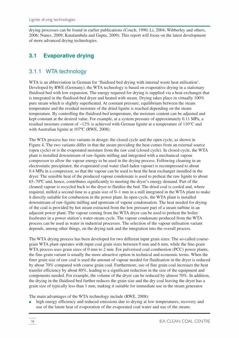
3.1.1 WTA technology
WTA is an abbreviation in German for ‘fluidised bed drying with internal waste heat utilisation’.Developed by RWE (Germany), the WTA technology is based on evaporative drying in a stationaryfluidised bed with low expansion. The energy required for drying is supplied via a heat exchanger thatis integrated in the fluidised-bed dryer and heated with steam. Drying takes place in virtually 100%pure steam which is slightly superheated. At constant pressure, equilibrium between the steamtemperature and the residual moisture of the dried lignite is reached depending on the steamtemperature. By controlling the fluidised-bed temperature, the moisture content can be adjusted andkept constant at the desired value. For example, at a system pressure of approximately 0.11 MPa, aresidual moisture content of ~12% is achieved with German lignite at a temperature of 110°C andwith Australian lignite at 107ºC (RWE, 2008).
The WTA process has two variants in design: the closed cycle and the open cycle, as shown inFigure 4. The two variants differ in that the steam providing the heat comes from an external source(open cycle) or is the evaporated moisture from the raw coal (closed cycle). In closed cycle, the WTAplant is installed downstream of raw-lignite milling and integrated with a mechanical vapourcompressor to allow the vapour energy to be used in the drying process. Following cleaning in anelectrostatic precipitator, the evaporated coal water (fuel-laden vapour) is recompressed to about0.4 MPa in a compressor, so that the vapour can be used to heat the heat exchanger installed in thedryer. The sensible heat of the produced vapour condensate is used to preheat the raw lignite to about65–70ºC and, hence, contributes significantly to meeting the dryer’s energy demand. Part of thecleaned vapour is recycled back to the dryer to fluidise the bed. The dried coal is cooled and, whererequired, milled a second time to a grain size of 0–1 mm in a mill integrated in the WTA plant to makeit directly suitable for combustion in the power plant. In open cycle, the WTA plant is installeddownstream of raw-lignite milling and upstream of vapour condensation. The heat needed for dryingof the coal is provided by hot steam extracted from the low pressure part of a steam turbine in anadjacent power plant. The vapour coming from the WTA dryer can be used to preheat the boilerfeedwater in a power station’s water-steam cycle. The vapour condensate produced from the WTAprocess can be used as water in industrial processes. The selection of the vapour utilisation variantdepends, among other things, on the drying task and the integration into the overall process.
The WTA drying process has been developed for two different input grain sizes: The so-called coarse-grain WTA plant operates with input coal grain sizes between 0 mm and 6 mm, while the fine-grainWTA process uses grain sizes of 0 mm to 2 mm. For pulverised coal combustion (PCC) power plants,the fine-grain variant is usually the more attractive option in technical and economic terms. When thefiner grain size of raw coal is used the amount of vapour needed for fluidisation in the dryer is reducedby about 70% compared with coarse grain coal. Furthermore, use of fine grain coal increases the heattransfer efficiency by about 80%, leading to a significant reduction in the size of the equipment andcomponents needed. For example, the volume of the dryer can be reduced by almost 70%. In addition,the drying in the fluidised bed further reduces the grain size and the dry coal leaving the dryer has agrain size of typically less than 1 mm, making it suitable for immediate use in the steam generator.
The main advantages of the WTA technology include (RWE, 2008):� high energy efficiency and reduced emissions due to drying at low temperatures, recovery and
use of the latent heat of evaporation of the evaporated coal water and use of the steam;
16 IEA CLEAN COAL CENTRE
Lignite drying technologies

� high drying capacity per dryer unit;� compact design;� safe plant operation as drying takes place in an inert atmosphere (avoidance of explosive coal
dust mixtures);� flexibility to drying task.
The fine-grain open cycle variant was chosen for the first pilot WTA plant at RWE’s lignite-firedUnit K at Niederaussem power plant. This fully-assembled WTA system enables 30% of the firingcapacity to be supplied by dried lignite, equivalent to around 210 t/h (or 110 t/h of dry lignite),ensuring that meaningful experience of dry lignite combustion is gained.
With a WTA process, depending on the drying variant and the moisture content of the raw lignite, the
17Update on lignite firing
Lignite drying technologies
raw lignitemilling
raw lignitepreheater
condensate
dry lignite0-1 mm
raw lignite0-80 mm
electrostaticprecipitator
dryervapour compressor
circulation blower
dry lignite cooler
dry lignite milling
raw lignitemilling
condensate
dry lignite0-1 mm
raw lignite0-80 mm
electrostaticprecipitator
dryer
circulation blower
dry lignite cooler
dry lignite milling
vapour to atm
vapourcondensate
boiler feed water
vapourcondenser
LP-steamfor heating
a) process principle of WTA fine-grain drying with vapour recompression
b) process principle of WTA with vapour condensation
Figure 4 WTA process with closed and open cycle (RWE, 2008)

overall efficiency of a power plant may be increased by four percentage points. Investment costs arenot expected to increase compared with conventional lignite-fired power plants because the additionalcosts associated with the dryer are almost offset by the savings in the boiler island (elimination of rawcoal bunkers, beater wheel mills and flue gas recirculation ducts for drying purposes) and reduction inthe flue gas path, including flue gas cleaning, which is lessened because of the smaller flue gasvolume and the efficiency increase (Stamatelopoulos, 2007). RWE is currently commercialising itsWTA process.
3.1.2 DryFining™
DryFining™ is a lignite fuel enhancement system that both dries and beneficiates raw lignite coals.Developed in the USA by a team led by Great River Energy (GRE), DryFining™ is a process thatuses waste heat from the power plant to evaporate a portion of the fuel moisture from the lignitefeedstock in a fluidised-bed coal dryer before it is fed into the boiler. Typically, about 45% of the fuelheat generated by a conventional pulverised coal fired power plant is lost in the condenser, andanother 20% exits the stack. The DryFining™ exploits this heat, which otherwise has little usebecause of its low quality. Heated air is used as heating and fluidising medium in the dryer. Figure 5provides a simplified flow diagram of the DryFining™ process. Warm cooling water from the turbineexhaust condenser goes to an air heater where ambient air is heated before being sent to the fluidised-bed coal dryer. The cooling water leaving the air heater is returned to the cooling tower. A separatewater stream is passed through coils in the fluidised-bed coal dryer (a multi-stage dryer is used toenhance heat transfer). The purpose of these coils is to provide additional heat to the fluidised bed toreduce the amount of air required. The dried coal leaving the fluidised bed is sent to a pulveriser andthen to the boiler. Air leaving the fluidised bed is cleaned of dust before being discharged into theatmosphere.
Funded by the US DOE as one of the Clean Coal Power Initiative projects, tests of DryFining™ on aprototype fluidised-bed coal dryer with a capacity of 115 t/h were carried out at Unit 2 of GRE’s CoalCreek Station in Underwood, North Dakota, in 2006. The test results showed that pre-drying coal withDryFining™ not only reduced the moisture content of the coal resulting in improved boiler efficiency
18 IEA CLEAN COAL CENTRE
Lignite drying technologies
fluidised bedcoal dryer
dryerproduct
coal
cooling tower
wet feed coal
air heater
condenser
boiler
boiler feed pump
fan
ambientair
hot airturbine
waste heat out
waste heat in
water
waste heat outbag
house
moist air
water
32°C circulatingcooling water
hotwater
49°C
pulveriser
air
waste heat in
waste heat out
Figure 5 Schematic of DryFining™ process using waste heat from condenser water and fluegas (NETL, 2007)

and unit heat rate, but the emissions of SO2, CO2, NOx and particulate were also reduced. Encouragedby the results and having recognised the economic benefits of this technology in previous trials, GREdecided to go beyond the scope of the second phase of the US DOE project to demonstrate thetechnology at commercial scale at Unit 2 and self-funded another installation of four dryers on Unit 1.Controlled tests with wet and dried lignite were conducted in March/April 2010 after the commercialcoal drying system was commissioned (NETL, 2007; Bullinger and Sarunac, 2010). GRE is nowready to commercialise this technology.
3.1.3 Entrained flow drying
This is the drying system integrated into the IDGCC (Integrated Drying Gasification CombinedCycle) process that is being developed by HRL in Victoria, Australia. Entrained flow drying has alsobeen proposed as a low-cost stand-alone dryer. In the IDGCC process, the hot gas from an air-blownfluid bed gasifier is used to pre-dry the coal in an entrained flow dryer through direct contact underpressure. The feed coal is pressurised in a lock hopper system and then fed into the dryer where it ismixed with the hot gas leaving the gasifier. The heat in the gas is used to dry the coal whilst theevaporation of the water from the coal cools the gas without the need for expensive heat exchangers.The coal dryer is smaller and cheaper to build than conventional coal dryers because it operates underpressure.
3.1.4 Superheated steam drying (SHSD)
The use of superheated steam drying has a number of advantages such as reduced risk of spontaneousignition/fire due to the absence of oxygen, increased drying rates and energy efficiency, reduction indust emissions, and improved grindability. It was also observed that the sulphur and sodium content oflignite coals could be reduced during superheated steam drying above 300ºC. A desulphurisation rateof between 40% and 50% at steam temperatures between 300ºC and 500ºC was reported. In general,the pure superheated steam environment primarily reduced the inorganic sulphur content of the coal.However, steam processing environments that had a small amount of air did provide significantreductions in the organic sulphur content as well. Depending on the type of coal and the steamtemperature, the sodium content of the coals could be reduced by 50–90% at steam temperaturesbetween 270ºC and 320ºC (Karthikeyan and others, 2009).
Because of the above mentioned advantages,SHSD is currently receiving increased interestfor coal drying. One example is the WTAprocess discussed earlier. Another example isdrying of lignite using Keith Engineering’sSHSD process. Lignite from the Loy Yanglignite mine in Victoria, Australia, was testedusing a superheated steam rotary dryerdeveloped by Keith Engineering as shown inFigure 6. The average coal particle size was8 mm. The feed rate of lignite was 23–46 kg/hand steam temperature was 180–230ºC with adrum rate of 3-6 rpm. Under these conditions,over 80% water removal was achieved and themoisture content of the lignite was reducedfrom 61% to 11%. Feed rate and inlet steamtemperature were found to be significantparameters governing the process. SHSD wasused for drying of Indonesian coal of
19Update on lignite firing
Lignite drying technologies
wetcoal
fan
dry coal
condensate
water
condenser
rotating drum
preheater
cyclone
Figure 6 A schematic of Keith Engineering’ssuperheated steam rotary dryer(Karthikeyan and others, 2009)

relatively low moisture content that was rich in sulphur. A steam temperature of 300ºC was found tobe sufficient to remove the moisture to the expected level (Jaugam and others, 2011).
3.1.5 Coldry Process
Developed by Environmental Clean Technologies Ltd (ECT), Australia, the Coldry process is a coalupgrading technology that removes high moisture content and certain pollutants from lignite andsubbituminous coals, hardens and densifies the coal, and increases the heating value of low grade coalto more than 24 MJ/kg. These transform the coal into a stable, exportable black coal equivalentproduct for use by black coal fired power generators. A unique feature of the process is attritioningand extruding where the water is expelled from coal via an exothermic chemical reaction. The dryingtakes place under low temperature and low pressure so low grade waste heat from a neighbouringpower plant can be used to facilitate the drying. The flow sheet of the Coldry process is shown inFigure 7. Lignite with moisture content between 30% and 70% is milled to particle size <8 mm indiameter and fed into a storage hopper (surge bin) where foreign objects are removed by screening. Asmall quantity of water (up to 5% depending on the moisture content of the raw lignite) is then added,and the coal/water mixture is fed into an attritioner in which the coal particles are rubbed together.This initiates an exothermic chemical reaction that triggers a natural process for expelling water fromthe coal. The reaction accelerates when the now plasticised mixture is extruded under low pressure.The extruded mixture is then sent to the conditioning unit in which warm air of around 40ºC heats themixture for about an hour. At this point, the extruded product hardens, contracts and separates intopellets. The pellets formed are conveyed to a vertical packed bed dryer. Warm air from an adjacentpower plant is circulated through the dryer to remove moisture from the pellets. The final moisturecontent of the product ranges between 10% and 14% depending on the water content andcharacteristics of the raw lignite, the drying temperature and drying time. The highly saturated warmair exiting the dryer at around 30ºC is cooled causing the water vapour to condense. The water iscollected and may be used in a neighbouring power plant or for other commercial purposes.
ECT claims that the Coldry system is reliable and easy to maintain. It operates at low temperature andlow pressure and thereby reduces energy consumption and extends equipment life. The Coldry pelletscan be burnt for power generation but also provide an ideal feedstock for coal-to-liquid and coalgasification systems. A mixture of raw lignite and 10–30% Coldry pellets can be used in existinglignite-fired plants without modification to the plant, reducing CO2 emissions by 5% to 15%. It ispossible to fire 100% Coldry pellets in significantly upgraded lignite plants(http://www.ectltd.com.au/).
20 IEA CLEAN COAL CENTRE
Lignite drying technologies
black coal plant100%
powergeneration
conditioningattrition &extrude
feedcontrol drying
coldrypellets
water
chemicalpowerstation
waste heat
lignite urea
oil
char products
export markets
Coldry process
Coldry plant
brown coal plant10-30% mix
Figure 7 Coldry process (http://www.ectltd.com.au/wp-content/uploads/ColdryProcess21.jpg)

The Coldry Pilot Plant was established as a batch production facility in 2004. Further developmentduring 2007 focused on the integration of its water recovery system and modifications to achievecontinuous, steady-state production. In early 2011 a new mixer-extruder kit was installed and tested.The results showed that the new equipment could further increase production capacity while allowingongoing refinement and calibration of the process for improved commercial scale design. Themaximum production capacity of the plant is now around 20,000 t/y. It is currently run for testing anddemonstration purposes, with some production sold into the local Victorian market to help offset someof the development cost.
3.1.6 Microwave drying
Microwave drying exploits the fact that water is super-absorbent to microwave energy. The water isheated at a molecular level, no matter where it occurs in the coal. Correspondingly, microwave energycan be efficiently delivered to both free and inherent water in the coal whilst the geological make-upof coal is largely transparent to microwave energy. By controlling the microwave energy applied andthe residence time, water in coal can be removed effectively by vaporisation while the coal massremains at low temperatures. This low temperature drying thus maintains the coal mass as intact aspossible, preventing the deterioration of the coal’s original thermal and other properties byoverheating. However, the presence of impurities can result in hot spots, and high dielectric losses forcoal can also result in fire hazards during drying. Further, it is difficult to comment on the costinvolved for handling a large amount of coal (Jaugam and others, 2011).
Drycol® processUnder development by DBAGlobal Australia Pty Ltd through the Drycol® Project, the process involvesexposing a continuous stream of coal to a controlled level of microwave energy to reduce its moisturecontent to a desired level. The moisture content of the product can be easily and precisely controlledthrough power setting and adjusting the conveyor speed. The microwaves have no particular heatingeffect on the coal, but efficiently target and drive off the water molecules situated on, around, or withinit. The moisture is drawn off as a vapour, and may be condensed as a useful source of clean water. Thebasic concept of the Drycol® process is shown in Figure 8. The crushed raw coal is loaded onto a
conveyor as a bed of fixed depth and conveyedcontinuously through a microwave-energisedchamber for the moisture in coal to be removed.The coal temperature is maintained at or below90ºC so that the processed coal neitherdevolatilises nor combusts. The process can beinstalled at a site remote to the power plant or atthe existing power plant site. Also, the drying ofcoal can be performed during off-peak hours,minimising costs through load shedding(Graham, 2006).
A 15 t/h Drycol® plant was operated to commercially dry coal from 28% moisture content to l2% asreplacement for coal destined for power generation. Tests on washed metallurgical coals showed thatdrying efficiency in the range 62–94% could be achieved using the Drycol® process (Graham, 2006).It was reported that microwave drying was much faster than the conventional coal drying. In somecases, it results in reduction of impurities such as sulphur, potassium, and phosphorous depending oncoal type.
CoalTek ProcessDeveloped and commercialised by a Georgia-based company, CoalTek Inc, this is a microwave-basedprocess which removes moisture, ash, sulphur, and mercury from low rank coals and transforms theminto cleaner burning fuels with an energy content increased by as much as 50%. This low temperature
21Update on lignite firing
Lignite drying technologies
condenserto sump
returnedwater
driedcoal
wave guide
MWgenerator
MWapplicator
feedhopper
wet coal
conveyor
MWabsorber
saturated air
Figure 8 The Drycol® process (Graham, 2006)

process is applicable to both thermal and metallurgical coal, and is capable of removing moisturewhile preserving the key metallurgical properties of coking coals. Typically, 40–50% moistureremoval is achievable. It is claimed that all CoalTek by-products are captured, filtered and separated,meeting environmental standards. CoalTek has not revealed its technology so details of the process areunknown. CoalTek opened its first commercial processing facility in Calvert City, Kentucky, USA in2006 and the plant’s initial capacity of 120 kt/y will be expanded in the future(http://www.coaltek.com/). There are also plans to build additional CoalTek plants in China and USA.
3.1.7 High velocity air flow grinding/drying
This type of drying technology utilises high velocity and high pressure air to shatter coal particles sothat moisture contained within the coal pore structures can be released. The sonic velocity air flow isso destructive that coal is instantly converted into a micron-sized fine powder with negligible moisturewithin. Since both the moisture content and particle size of coal decrease, drying and grinding can beachieved simultaneously, thus eliminating the difficulties attendant with grinding sticky low rankcoals.
Windhexe technologyDeveloped by a US company Vortex Dehydration Technology, LLC (VDT), this technology is nowcommercially available for food processing and other industries. The Windhexe technology claims tobe able to mill and dry coal simultaneously. The process showed the expected attribute of drying byevaporation but also produced a mechanical separation of moisture. The swirling air dehydrates thematerial using a combination of mechanical and evaporative energy and is therefore more efficientthan any thermal drying device. The Windhexe device is described in a US patent as a cyclone withinlet tangential velocities equal to or approaching sonic velocity. The high velocity is achieved by theuse of compressed air which is usually heated prior to entering the cyclone. The claimed energyrequirement to remove water from coal is significantly less than water evaporation. The mechanismfor achieving this is unknown (Wibberley and others, 2006).
According to VDT, over 800 tests of various materials were carried out and some of the mostsuccessful were energy related, especially coal. The Windhexe technology has been tested byInternational Power at the Hazelwood power plant to dry Australian lignite coal.
DevourX millDevourX mill is a vortex-based machine that is under development by DevourX Plc (Malaysia). Itgrinds and dries coal simultaneously using aeroacoustics rather than mechanical force. Aeroacousticsis the science of acoustic noise generation caused by aerodynamic forces interacting with surfaces.Around 1034 MPa pressure is reached through a combination of air speed and sound. The particles areaccelerated from 0 to 100 km/h in 1 m of travel. Tuning of the machine is critical because the soundfrequencies shatter the particles, followed by communition as the particles collide. Coal cells are‘pulled’ apart and water is ‘ripped’ off from the coal particle converting clumpy wet lignite into a fineflowable powder that is carried in the air flow into the furnace (Godfrey, 2010).
DevourX claims that the system brings a number of economic benefits such as its high efficiencyleading to reductions in processing costs and energy consumption, and a much smaller space isrequired for installation and less maintenance is needed during operation resulting in significantsavings in capital and operational costs. Another advantage DevourX has over conventional drying isthat it breaks the cellular structure of coal which liberates the colloidal moisture contained within thecells. Drying is achieved without the use of heat. However, the drying efficiency of DevourX can beenhanced by utilising the waste heat produced in a power plant.
LamiFlo™ systemDeveloped by a UK-based company LF Pumping (Europe) Ltd, the LamiFlo™ system is an integrated
22 IEA CLEAN COAL CENTRE
Lignite drying technologies

electricity-driven process that can be used for drying, transporting and grading more than 80 differentmaterials including anthracite, bituminous and lignite coals. The system consists of three bespokecomponents connected with coated steel flanged pipework: mass air generators, the Anudro™expansion chamber and the Euroclydon™ cyclone. The typical layout of a LamiFlo™ system isshown in Figure 9. A rotating Archimedes screw feeder feeds a moist feedstock into the Anudro™expansion chamber where the solid is mixed with compressed air supplied by the mass air generator.The mixture then travels along the delivery pipe at high velocity up to 3000 m/min into a sealedEuroclydon™ cyclone, where the aggregates are separated from the saturated air stream. During thetravelling, the air envelopes the moist solids and evaporates the surface moisture. The delivery pipe,typically 6 m long, can vary in length to suit the available space at a site. The process takes up to3 seconds for moist material to enter the system and dried material to exit. Up to 10% surfacemoisture content can be removed per pass through the system. The drying takes place in air at lowpressure but very high mass flow and no heat is used.
The LamiFlo™ drying system at low pressure removes free surface moisture. To reduce inherentmoisture, the pressure within the LamiFlo™ system can be increased which increases the temperatureof the air stream, resulting in inherent moisture reduction. In addition, particle reduction equipmentcan be incorporated to increase the surface to volume ratio of material and thereby enhance the dryingefficiency. The LamiFlo™ system has design simplicity, is reliable to operate and easy to maintain. Ifthe surface moisture content of a coal is to be reduced from 40% to 15%, the estimated operating costis 0.58 $/t at an output rate of 250 t/h or 0.63 $/t at an output rate of 500 t/h based on electricity costof 0.10 $/kWh (LF Pumping, 2011).
23Update on lignite firing
Lignite drying technologies
Anudro™ chamberwith hopper
Euroclydon™cyclone
mass airgenerator(s)
coalfeeder
Figure 9 Typical layout of a LamiFlo™ system
3.2 Non-evaporative dewatering
The earliest non-evaporative thermal dewatering process was developed in Austria in the 1920s and isknown as Fleissner drying. Since then a number of non-evaporative dewatering processes have beendeveloped and technical reviews of these processes can be found elsewhere (Couch, 1990;Katalambula and Gupta, 2009). Hydrothermal dewatering and mechanical thermal expression are thetwo major types of non-evaporative coal dewatering. The following sections discuss some of thenewer processes that are under development.
3.2.1 Hydrothermal dewatering (HTD)
In this process the coal is heated under pressure to temperatures in the range 250ºC to 310ºC. Underthese conditions, the coal structure breaks down and shrinks, and the water is released as a liquid.Several hydrothermal dewatering processes are in development and are emerging in the commercialmarket.
K-Fuel® Developed by Evergreen Energy Inc, a Colorado-based US company, K-Fuel® is a patentedtechnology for low rank coal drying and upgrading. The K-Fuel® process involves the heating and

pressurisation of low value coals, which irreversibly removes the water content thereby converting theproduct into a higher energy, lower emission fuel. The flowsheet of the K-Fuel® process is shown inFigure 10. In the K-Fuel® process, a low rank coal is fed into the K-Fuel® processor. Hightemperature (204–260ºC) and pressure (2.7–3.4 MPa) are applied in the processor to crush the coaland under such harsh conditions, the physical and chemical structure of the low rank coal is alteredtransforming the low rank coal into a cleaner, low-moisture and higher-CV fuel. A co-benefit of theK-Fuel® process is that it can also remove significant amounts of mercury (as much as 80%) andlower impurities present in the coal and thereby reduce overall emissions of SOx, NOx, CO2 and Hgfrom coal-fired power plants.
A 750,000 t/y commercial K-Fuel® plant was built in Gillette, Wyoming, USA and operation,modification and test burns were carried out from December 2005. Based on the operatingexperiences obtained at the plant, the K-Fuel® process was redesigned in 2008 by Bechtel PowerCorporation. This enhanced K-Fue® process design offers significant process, economic, andenvironmental improvements and it is now the template for Evergreen’s business developmentactivities in the USA and abroad (Burton, 2011; Katalambula and Gupta, 2009).
24 IEA CLEAN COAL CENTRE
Lignite drying technologies
Hg removal
boiler/utility fuel
product
processsteamboiler
condenserfeed coal
processvapour
K-Fuel®/Lurgiprocessor
process steam
204-260°C2.7-3.4 MPa
water ( removal)
rotarycooler/stabiliser
Figure 10 Flowsheet of the K-Fuel® process (www.evgenergy.com)
Table 5 Quality improvements in K-Fuel® products (Burton, 2011)
CoalMoisture % Higher heating value, MJ/Kg Hg
removal*%raw coal dried coal removal % raw coal dried coal increase %
Source 1 31.72 14.00 55.9 16.42 21.11 28.6 51
Source 2 44.96 14.80 67.1 14.92 23.72 59.0 68
Source 3 64.12 22.00 65.7 9.33 21.22 127.4 95
Source 4 51.91 24.60 52.6 13.15 21.52 63.6 54
Source 5 50.06 14.30 71.4 13.41 23.65 76.4 79
Source 6 26.95 13.20 50.0 20.05 24.54 22.4 43
* based on mass per unit of energy

A number of lignites and subbituminous coals including coals from Inner Mongolia, Indonesia, Russiaand the USA were tested and examples of the improvements in coal quality achieved by K- Fuel®process are shown in Table 5. As one can see from Table 5, the K-Fuel® process is capable ofreducing moisture content of low rank coals by more than 50%. The heating value of the coals wasincreased as a result , and in one incident the high heating value of a coal was more than doubled afterdrying. In addition, the mercury content of coals can be effectively removed by the K-Fuel® processresulting in a significant reduction in Hg emissions from power plants. The K-Fuel® treated coalswere test burned in several US power generation facilities and the results confirmed the improvedcombustion efficiency and reduced air emissions. Evergreen Energy is now actively working tocommercially deploy this technology globally. In 2010, Evergreen Energy reached an agreement witha Chinese company to establish a joint venture, which signed a letter of intent with a large Chineseutility and chemical producer to explore ways in which the K-Fuel® technology could be applied atan inland coal chemical facility that was under development. In 2011, Evergreen Energy signedagreements with an Australian mining company WPG Resources to set up a joint venture to developand deploy the K-Fuel® technology throughout Australia (www.evgenergy.com).
Continuous Hydrothermal Dewatering (CHTD)An Australian company, Exergen, has developed CHTD which been successfully demonstrated at pilotscale on coals from Australia and other international locations. Core to the CHTD technology is avertical autoclave that uses gravitational head pressure and a small amount of energy to transform themolecular structure of lignite/brown coal to remove up to 80% of its moisture content. The use ofgravitational pressure and high heat recovery design means that less than 2% of the coal’s energy isused to achieve greater than 60% reduction in water content for Victorian lignites. A schematicprocess flow of CHTD is shown in Figure 11.
The process utilises efficient heat and pressure recovery to achieve the decarboxylation oflignite/brown coal. Heat recovery is greater than 90% due to efficient autoclave design. The processexerts 10 MPa and 300ºC upon a brown coal slurry for a period of a few minutes. These conditionsalter the molecular structure of the coal, collapsing pores within the coal particle and making it unableto hold as much moisture. The coal changes from being hydrophilic (water attracting) to hydrophobic(water repelling), allowing the water to be removed from the coal more easily. The chemicaltransformation of the coal reduces its ability to carry moisture, which lowers its equilibrium moisturecontent, making it less likely to absorb atmospheric moisture. The water is extracted from the coal in aliquid state, producing a coal with higher energy density. Furthermore, some impurities in the coal areremoved in the CHTD process resulting in a coal with improved combustion characteristics. Forexample, soluble inorganics are separated from the coal with the water. Up to 60% of sodium is
25Update on lignite firing
Lignite drying technologies
as-minedcoal
export product
300°C and100 MPa
decarboxylationtakes place here
solid/liquidseparation
CHTD autoclave
feed coal
recycledprocess
waterwater treatment
autoclaveprocess water
treatedprocess water
treatedcoal
treated coal
treated coal slurrycoal slurry
size reduction
Figure 11 CHTD process (Exergen, 2009)

removed, reducing the power station maintenance costs associated with boiler slagging. Densecomponents of the ash (such as quartz) may be removed from the coal slurry, leading to reduced wearon power station equipment. As an additional benefit, the water extracted from the coal can meet up to40% of the make-up requirement for power station cooling. Exergen claims that the CHTP process issimple, continuous with a small footprint and can be readily up-scaled to a feed rate of thousands oftonnes per hour (Exergen, 2009).
Having successfully proved the CHTD concept in its 4 t/h pilot plant, Exergen has been working onscaling up to a 50 t/h demonstration plant and after that Exergen plans to build a 4000 t/hcommercial-scale facility adjacent to a new 30 Mt/y brown coal mine in Latrobe Valley (LV),Australia that is under development by Exergen to upgrade LV brown coal for export(www.exergen.com.au).
Hot Water Drying (HWD)Developed by researchers at the Energy and Environmental Research Center (EERC) of the Universityof North Dakota, the HWD process uses high temperature and high pressure to dry a coal in a watermedium. In the HWD process, ground wet coal is treated at coal-specific temperatures, beginning atas low as 240°C and the corresponding saturated steam pressure for less than ten minutes. Moisture isremoved from the coal by expansion and expulsion from the micropores by CO2, which is liberatedduring decarboxylation. Devolatilised tars/oils, which are hydrophobic, remain on the coal surface inthe pressurised aqueous environment. It is hypothesised that this produces a uniform coating that sealsthe micropores and limits moisture reabsorption, which is a major advantage of the process. Becausethe coating retains most of the low-rank coal’s volatile matter, high energy recovery and excellentcombustion performance can be obtained. The developers claim that alkali cations, a major source ofboiler fouling, associated with the carboxyl groups, are released in the aqueous phase in the processand are removed during the final mechanical dewatering step.
The technical feasibility of HWD has been demonstrated in a 7.5 t/d pilot plant at the EERC with lowrank coals from around the world. Costs of dewatering will vary with coal grade and location. Itappears that the successful commercial low rank coal drying processes are those in which the driedlow rank coal is utilised immediately and not stored. When stored, the products from most dryingsystems can have stability problems, which result in excessive fine dust and spontaneous heating(Karthikeyan and others, 2009).
The Catalytic Hydrothermal Reactor Technology (Cat-HTR)An Australian company Ignite Energy Resources Pty Ltd (IER), is developing the catalytichydrothermal reactor technology which is designed to convert low value lignite and modern biomassinto non-conventional crude oil and various upgraded coal products. The Cat-HTR technology useswater at or near supercritical temperatures and pressures together with proprietary catalyst systems toselectively de-polymerise and de-oxygenate lignite and convert it into various higher density energyfuels and high grade clean coal products. A diagram of Cat-HTR process is shown in Figure 12. Thecompany has not disclosed much factual information so details of the technology remain uncertain.
A pilot scale Cat-HTR plant with capacity of 4000 t/y has been in operation since mid-2008. Based onthe pilot test results IER claims that Cat-HTR has the capability to convert 1.3 t of as-mined lignite(assuming 50% moisture) into up to one barrel of non-conventional crude oil and up to 0.34 t of highgrade micronised coal.
In 2010, IER signed a hosting agreement with TRUenergy, a Victorian-based utility company andsubsidiary of China Light & Power, to build a commercial Cat-HTR demonstration plant atTRUenergy’s site at Yallourn and to supply upgraded fuel products to TRUenergy’s existing lignite-fired power station (http://www.igniteer.com/).
26 IEA CLEAN COAL CENTRE
Lignite drying technologies

3.2.2 Mechanical thermal expression (MTE)
Studies undertaken by Professor Strauss and co-workers at the University of Dortmund, Germany in themid 1990s led to the development of MTE technology that combines the use of pressure and temperatureto effectively reduce the moisture content of lignite, while requiring significantly lower pressures
(<12 MPa) and temperatures (<200ºC). Theeffect of elevated temperature is to soften thecoal to reduce the mechanical pressure requiredfor dewatering. In the MTE process, raw ligniteis heated to a temperature in the range of 150ºCto 200ºC, at saturation pressure (0.5 to 2 MPa)to prevent evaporation. A mechanical pressureof around 6 MPa is then applied to squeeze thewater out of the lignite. A schematic of MTEprocess design is shown in Figure 13.
There has been active development of thistechnology in both Germany and Australia. InGermany, the development of the MTEtechnology has been undertaken by RWE incollaboration with other companies. Followingsuccessful trials at laboratory- and pilot-scaleusing batch process, a further development
step toward commercial implementation of the MTE process involved converting the discontinuouspilot press to quasi-continuous fully automatic operations, with a throughput of approximately 1.6 t/hof dried lignite. While testing the MTE technology, the feeding of the MTE press with coal in quasi-continuous operations, treatment of the raw lignite, and subsequent treatment of the dry ligniteproduced were also investigated. The various project phases provided evidence of the cost-effectiveness and energy-efficiency of dewatering lignite using the MTE process. After completion ofthis development, a 25 t/h MTE demonstration plant was constructed at RWE’s Niederaussem powerplant and was commissioned at the end of 2001. At the beginning of 2002 RWE took over thedemonstration plant but work was subsequently discontinued. RWE has chosen the WTA process forfurther development (Katalambula and Gupta, 2009; Bergins, 2005).
27Update on lignite firing
Lignite drying technologies
oil and speciality chemicals
ungraded coal and micronised carbon
gas
water
lignite
water +catalyst
‘agent of change’
heat recoveryheat exchanger
slurry tank+ pressure heater Cat-HTR
process
productseparation
potentialCO2 credits
Figure 12 Cat-HTR process diagram (http://www.igniteer.com/technology/lignite-upgrading/cat-htr-process.html)
steam
MTEwastewater
‘cold’
coal fill
pressure plateMTE
wastewater‘cold’
Figure 13 MTE process design (Wibberley andothers, 2006)

In Australia, the Cooperative Research Centre for Clean Power from Lignite (CRC Lignite) worked todevelop the MTE process suitable for Victorian lignites. The development plan involved theconstruction of a 20 t/h pilot plant in 2005 to 2006. The CRC’s MTE process used a differentconfiguration that had some features distinctly different from those of the German process. In theCRC’s process, the coal was fed as a slurry, which was preheated using energy extracted from the hotproduct coal and hot expressed water. The preheated coal slurry was then heated under pressure in aheating chamber to the required process temperature by saturated steam. The hot slurry from theheating chamber directly entered the compression cylinder under gravity. Dewatering occurredthrough both axial and circumferential filter surfaces. The circumferential filter surface, a feature ofthe CRC’s process, appeared to be more effective in dewatering than the axial surfaces. Thisimprovement meant that the dewatering in the CRC’s process was not as dependent on particle sizedistribution as was in the German process.
The CRC Lignite reported on the successful trial of the CRC’s MTE process for drying lignite andconcluded that this technology could provide a low cost, energy efficient process for partial drying(down to around 30% moisture) at the large scale required for power plant feed. The CRC Lignitefound the MTE less expensive than HTD or WTA process and capable of removing more than 70% ofthe water from the lignite from Victoria and South Australia, resulting in huge CO2 savings when thedry coal is burnt in a power station (Katalambula and Gupta, 2009; Wibberley and others, 2006).
The liquid water removed from coal by HTD and MET processes carries with it both organic andinorganic mater. The large volumes of acidic, salty, and organic-rich product water present a majorconcern of wastewater treatment difficulties and costs for disposal or reuse of the product waters. Theoverall viability of the processes will depend on the availability of a simple and energy-efficient waterremediation strategy. Investigations into ways of treating the wastewater from HTD and METprocesses were carried out by several researchers (Nakagawa and colleagues, 2004; Butler and others,2007) and more work in this area is needed.
3.2.3 Comments
When selecting a lignite drying process for power plant applications, factors such as throughput,energy consumption, material handling capabilities, safety, carbon footprint, capital and operatingcosts are important considerations. Although numerous technologies for coal drying already exist, notall are suitable for lignite drying and often they are complex and require high-grade heat to removemoisture from the coal. This significantly increases process cost, which represents a main barrier toindustry acceptance of the technology.
Extensive research and investigations have been carried out worldwide to develop energy efficient andcost effective coal drying processes. A number of approaches are taken to dry lignite and other lowrank coals. The variability and diverse nature of lignite properties make testing at pilot scaleimperative in the development of new drying technologies. Furthermore, there is a need for carefuland systematic evaluation of dryer designs to maximise the efficiency, cost-effectiveness, and safety ofdrying equipment selected for a specific lignite application. Recently, several advanced coal dryingtechnologies have been developed and are offered to the commercial market, whilst many more areunder development. A comprehensive review on the recent developments in drying of low rank coal isavailable (Osman and others, 2011). This is an area that is developing rapidly.
28 IEA CLEAN COAL CENTRE
Lignite drying technologies

4 Pulverised lignite firing
29Update on lignite firing
The major challenge facing the power generation industry over the coming decades will be to increasethe efficiencies of fossil-fuelled power plants while also meeting more stringent environmental goals.Especially, there is a need to reduce the emissions of CO2 to the atmosphere, with near-to-zero CO2emissions being the ultimate goal. At the same time, plant reliability, availability, maintainability andoperational costs, as well as the cost of electricity (COE), must not be compromised. Pulverised coalcombustion (PCC) technology has continued to evolve over time from subcritical to supercritical (SC)and ultra-supercritical (USC) steam conditions leading to significant increases in unit efficiencies. Inaddition to the use of advanced steam cycles, technical innovations in system and process engineering,larger unit size, improved waste heat recovery from the flue gas, and optimisation of auxiliary powerneeds have all contributed to the plant efficiency increases and costs reduction. In the last ten years,significant improvements also have been achieved in reducing heat losses in the low-pressure end ofsteam turbines and in turbine blade designs, improving both efficiency and reliability of the overallgenerating units. As a result, today’s PCC power plants have very high levels of availability andreliability. Furthermore, the continued addition/retrofit of emission control systems to meetprogressively more stringent emission standards has resulted in significant reductions in air pollutantsemissions. In lignite-fired power plants, flue gas desulphurisation (FGD) systems are applied for SO2emissions control while NOx emissions control is mainly accomplished by primary measures.
4.1 Pulverised lignite firing process
In a conventional pulverised lignite fired boiler, the lignite fuel is fed into bunkers adjacent to theboiler. From there, the fuel is metered into several pulverisers which grind it to approximately200-mesh particle size. A stream of hot gas (flue gas drawn from the lower part of the boiler) isintroduced into the mills to dry the fuel and to convey it pneumatically to the burner nozzle where it isinjected into the burner zone of the boiler. Firing configurations of boilers that fire pulverised ligniteinclude tangential, horizontally opposed, front wall, and cyclone boilers.
In the tangential firing furnace, the pulverised lignite is introduced from the corners or walls of theboiler in vertical rows of burner nozzles. Such a firing mechanism produces a vortexing flame patternwhich essentially uses the entire furnace enclosure as a burner. In front-wall firing and horizontallyopposed firing boilers, the pulverised lignite is introduced into the burner zone through a horizontalrow of burners. This type of firing mechanism produces a more intense combustion pattern than thetangential design and has a slightly higher heat release rate in the burner zone itself.
In these methods of firing pulverised lignite, the ash is removed from the furnace both as fly ash andbottom ash. The bottom of the furnace is often characterised as either wet or dry, depending onwhether the ash is removed as a liquid slag or as a solid. PCC units have been designed for both wetand dry bottoms, but for lignite firing the current practice is to design only dry bottom furnaces.
Another type of boiler firing lignite is the cyclone boiler, which is a slag-lined high-temperature vortexcombustor. The coal is fed to a crusher that reduces the lignite into particles of approximately 0.6 cm(0.25 inch) in diameter or less. Crushed lignite is partially dried in the crusher and is then fired in atangential or vortex pattern into the cyclone boiler. The temperature within the furnace is hot enough tomelt the ash to form a slag. Centrifugal force from the vortex flow forces the melted slag to the outsideof the combustion zone where it coats the boiler walls with a thin layer of slag. As the solid ligniteparticles are fed into the boiler, they are forced to the outside of the combustion zone and are embeddedin the slag layer. The solid lignite particles are trapped there until complete burn-out is attained. The ashfrom the furnace is continuously removed through a slag tap which is flush with the furnace floor(US EPA, 1998). There are only a few lignite-fired power plants in operation using cyclone boilers.

Most lignite-fired power plants aroundthe world in operation today use PCCtechnology. The majority of existingpulverised lignite fired power plants arebased on the conventional single reheatthermal cycle with subcritical mainsteam pressure in the range 13–20 MPaand main/reheat steam temperaturesboth around 540ºC. There are some old,small, lignite-fired generating units thatare still in operation with main steampressure at or under 10 MPa and someof them have main steam temperatureswell below 500ºC (IEA CCC, 2011).
Recent advances in boiler and turbinematerials have led to the installations ofhigh efficiency supercritical and ultra-supercritical PCC steam generators. Inmodern lignite-fired power plants,steam pressures up to 27.5 MPa andmain/reheat steam temperatures as highas 600ºC/605ºC have been applied, andthe net plant efficiency of >43% hasbeen achieved. Improvements inprocess design and engineering not onlyincreased the total plant efficiencies, butalso improved the availability,flexibility and environmentalperformances of the plants and reducedcapital and operating costs. Technicaladvances in system and processengineering include (Mandel andSchettler, 2007; Wolff, 2011):� improved low NOx burners;� an optimised heat cycle for theregenerative preheat unit;
� the reduction of condenser pressure;� improved recovery and utilisation ofwaste heat from the flue gas;
� the use of efficiency-improvedbladings at the steam turbines;
� increased use of fibre-glassreinforced plastics and flue gas drawoff through the cooling tower;
� the introduction of highly efficientafter-burning grates with residues oflower than 1% of unburnt material;
� combustion chamber cleaning withthe help of water jet sprayers.
Figure 14 shows the efficiency gains ofRWE’s 950 MWe BoA unit fromimprovements in lignite-fired power
30 IEA CLEAN COAL CENTRE
Pulverised lignite firing
mea
nef
ficie
ncy
gai
n of
a95
0 M
WB
oA u
nit
stea
m g
ener
ator
with
inte
gra
ted
NO
x re
mov
al
cool
ing
tow
er
gen
erat
orE
SP
FGD
coal
mill
wet
ash
raw
ligni
te
dry
ash
gyp
sum
flue
gas
cool
er
com
bus
tion
air
feed
hea
ter
cond
ense
r
turb
ine
air
heat
erb
ypas
s ec
onom
iser
Red
uced
con
den
dse
r p
ress
ure
than
ks to
op
timis
edco
olin
g to
wer
+1.4
%
Was
te g
ash
eat
uti
lisat
ion
+0.9
%
Incr
ease
inst
eam
par
amet
ers
+1.3
%
Pro
cess
op
tim
sati
on
+1.1
%
Imp
rove
dtu
rbin
e ef
fici
ency
than
ks to
ad
vanc
edst
eam
turb
ine
+1.7
%
Red
uced
auxi
liary
po
wer
req
uir
emen
ts
+1.3
%
31%
Year
195
7av
erag
e ne
tef
ficie
ncy
of a
150
MW
unit
net
effic
ienc
yof
BoA
43.2
%
Year
200
3
35.5
%
Year
197
6av
erag
e ne
tef
ficie
ncy
of a
600
MW
unit
Year
40 35 30
efficiency, %
4550
1970
1980
1990
2000
2010
1960
Figure 14 Efficiency gains of a RWE’s BoA unit fromimprovements in lignite-fired power plantprocess and engineering design (RWE Power,2011)

plant process and engineering design. BoA is the abbreviation of ‘the lignite-fired power station withoptimised plant engineering’ in German. With BoA Plus, which is BoA technology plus WTA lignitepre-drying technology, the plant efficiency can be further increased by up to four percentage points.Some of the new design concepts for pulverised lignite fired power plants will be reviewed in thefollowing sections.
4.2 Lignite milling
The milling plant for lignites is fundamentally different to the mills for bituminous/hard coals. Thekey issue for pulverising lignites is to achieve adequate drying and to avoid mill fires. This is achievedusing flue gas in addition to air for drying and this gives the heat required and also reduces the oxygenconcentration in the mills to a level where explosions cannot occur. Due to the soft nature of lignitecoal, beater wheel mills are normally used to pulverise the lignite to achieve defined fineness and tolower its moisture content to the desired level to ensure efficient combustion of the fuel. A beaterwheel mill crushes, shatters, or pulverises lignite upon impact. The fineness of pulverised coal isusually assessed on the basis of the residues on the 1 mm sieve. The typical values for pulverisedlignite are well below 10% (usually between 3% and 6%), depending on quality of coal, thecombustion system and boiler size.
In order to provide pulverised lignite with the required fineness, moisture content and fuel flow rate,several modifications and improvements on the existing beater wheel mills were implemented andtested. Various types of beater wheel mills are shown in Figure 15.
4.2.1 Beater wheel mill with classifier
The lignite processing takes place in the mills without staged grinding. The mills are equipped withclassifiers. These classifiers are static separators with no moving parts. The use of the classifiersensures that the residue on the 1 mm sieve does not exceed 3% to 5%. The fraction of <63 µm isequivalent to about 70–90%.
31Update on lignite firing
Pulverised lignite firing
mill with classifier mill with vapour separator classifier mill with staged grinding
Figure 15 Types of beater wheel mills (VGB, nd)

These devices employ gravity deflection to separate the coarse dust fractions from fuel dust/gasmixture and return the coarse grains to the mill for further grinding. These classifiers cannot meet theincreasing demands of modern large lignite-firing plants – in particular the flame stability at varyingboiler load because the low O2 content of carrier gas and high moisture content of the fuel have anegative effect on coal ignition and combustion efficiency.
4.2.2 Beater wheel mill with vapour separation classifier
This is an improved version of the mills discussed above through the use of vapour separationclassifiers. The vapour separation classifier performs two tasks: it separates the coarse grains from thefuel dust/gas mixture and returns them to mill for further processing, and it splits the mixture intofuel-rich and fuel-lean vapour streams. The split streams are then fed to the combustion chamberseparately. The degree of vapour separation can be set, for example, 90% fuel dust and 70% gas in thefuel-rich stream, and 10% fuel dust and 30% gas in the fuel-lean stream. The fuel-rich stream isinjected into the boiler through lower main burners and the fuel-lean vapour stream is injected throughthe remaining upper part burners or through additional vapour burners above the main burners.
4.2.3 Beater wheel mill with staged grinding
For some lignites with high hardness and poor grindability, beater wheel mills with stagedpulverising/grinding can be used to achieve the required fineness. The mills are designed withoutclassifiers. The grinding of the mills is subject to greater fluctuations due to the lack of classifiers andthe residue on the 1 mm sieve is, on average, 6–9%.
Mills with classifiers/vapour separation classifiers and with staged grinding are also available, whichcombine the features discussed above.
The mill design for the RWE’s BoA 2 and 3 at Neurath Power Plant (Germany) features a three-stageprebeater and a beater wheel with a diameter of 4.3 m. The two-stage grinding process ensures therequired product fineness of <6–10% residue on 1 mm sieve being maintained independent from loador lignite quality (Habermann and others, 2004).
The number of mills in operation depends on calorific value at nominal load. Apart from the numberof mills in operation the mill conveying volume is adapted to the coal quality by the means of millspeed control and conveying gas recirculation. The mills are arranged symmetrically around thefurnace and they feed dried and finely-ground lignite directly to the corresponding burner columns.
In general, for lignite/brown coal combustion there are no special demands on the fineness of thepulverised fuel in order for primary NOx emissions control. However, finer fuel particles may reducedeposition and slagging problems.
4.3 Low NOx burners
The design of a furnace is strongly governed by the burners to be installed. Their arrangement andperformance determine the size and shape of the furnace. The burner performance also influences themill design to a certain extent. Therefore, the burner is the key element in the design of a firingsystem.
Most existing lignite-fired units in Europe use tangential firing system with jet burners, where theflame is stabilised in the central fireball instead of individual vortex burners. These jet burners areactually not burners but coal injectors which means that lignite coal ignites 2–4 m from the nozzle in
32 IEA CLEAN COAL CENTRE
Pulverised lignite firing

the central fireball. Due to the low O2 content of the carrier gas, the ignition and flame stabilisationare inferior with such a jet burner. This results in a narrow operating range for boilers, typically50–100 % and under low load operation it is necessary to use oil or gas for flame stabilisation and forsafe boiler operation. These burners also result in high NOx emissions and suffer slagging problems.
Babcock-Hitachi and Enprima Engineering developed a new type of low NOx burner called NR-LE(NOx Reduction – Load Extension) burners for lignite combustion that apply the ‘high temperature’philosophy. The basic feature of a firing system using the NR-LE burners is that a sub-stoichiometriczone is formed very close to the burner nozzle, and two-stage combustion is carried out by means of asingle burner flame. This single burner staging technique combined with staging in the main vortex byOFA (over fire air) is very effective in reducing NOx emissions (Yano and others, 2003).
In order to reduce slagging in lignite fired units, sometimes it is necessary to increase the verticaldistance between burner levels to reduce the burner zone heat release rate related to temperature in theburner zone, and to modify the corner geometry so that flame impingement on the furnace wall isprevented. Figure 16 shows the principle of the new combustion system with the NR-LE burners.Furthermore, the NR-LE burner can control the flame pattern making it possible to avoid the hightemperature influence on slagging to furnace corner walls.
The NR-LE burner found its first commercial application in Unit 2 at Vresová lignite-fired powerplant in Czech Republic in 2001. Results showed that after retrofitting NR-LE burners and
modifications to the OFA system, NOxemissions were reduced to lower than200 mg/m3. The boiler turndown ratio hasbeen improved and stable operation within thefull load range (30–100%) can be maintained(Yano and others, 2003).
With the use of CFD (computational fluiddynamics) modelling, Babcock Borsig PowerSystems (Germany) developed the RS burnerfor lignite combustion as shown in Figure 17.RS burners are characterised by stable flameswith ignition right at the burner tip. This leadsto a higher heat absorption in the lower part ofthe furnace. In 2000, the RS burners wereretrofitted to the 300 MWe units A and B at
33Update on lignite firing
Pulverised lignite firing
poor flamestability
min. load range50-70%
conventional burners
good flamestability
min. load range30-40%
new type burners
Figure 16 The new lignite combustion system with NR-LE burners (Yano and others, 2003)
flame stabiliser
secondary airdeflection throat
secondary air
pulverisedcoal
swirl insert
Figure 17 RS burner for lignite combustion(Tigges, 2003)

Neurath Power Station (Germany), which burns lignites of different qualities from two mines,Hambach and Garzweiler. The RS burners were installed in the burner opening of the former jetburners and similar to the jet burners, they are directed towards a tangential circle in the furnace. Onlyslight adjustments were made to the boiler pressure parts. The excellent low NOx performance of theburners resulted in reduced OFA requirement and therefore the uppermost of three OFA elevationssituated between the first tube banks could be removed without any increase in NOx emissions. Theparticle temperature at the furnace exit was 50°C to 70°C lower after the conversion and consequentlythe severe slagging and fouling at the furnace exit and first tube banks experienced previously weresubstantially reduced. Stable full load conditions and complete burn -out at the furnace exit were alsoachieved. Furthermore, with RS burners, higher burner air ratios and shorter residence times of fuelcombustion in reducing atmospheres are sufficient to meet the NOx emission requirements comparedto jet burners (Tigges, 2003).
4.4 Boiler design
4.4.1 Firing system
Lignite firing systems for utility boilers are mostly designed as tangential firing systems with main andreburning burners. The fuel is fed into the combustion chamber symmetrically. One mill feeds oneburner group. The uniform fuel supply to the furnace cross-section generates an optimum temperatureprofile with hot zones in the centre of the furnace cross-section and colder zones at the edge.Symmetrical firing configuration allows uniform heat flux and temperature distributions in the burnerarea which will reduce slagging. The burners are arranged in the corners to maximise the utilisation ofthe furnace volume and minimise the back-flow zones at individual burner. As a result, smaller amountsof hot flue gases containing unburnt coal particles reach the combustion chamber wall, which wouldotherwise cause fouling of the chamber wall. The pronounced radial temperature profile is produced bydirecting part of the secondary air towards the walls. This results in more combustion air in the wall areawhich leads to lower temperatures in the peripheral area which reduces the propensity for fouling.
Figure 18 shows an overview of the firing concept. It includes a combustion chamber for a 1050 MWesteam generator. The burner array of the combustion chamber corner consists of six dry lignite firedburners arranged one on top of the other. Each of these burners has been allocated a wall air opening.These fuel oil burners centred within the dry lignite burner and equipped with a swirl are used forignition firing.
This firing configuration with radial-staged air supply represents the state-of-the-art for modern hardcoal based firing systems. In addition to this type of air supply, two burn -out air levels are planned.This staged air supply concept guarantees compliance with the statutory emission values for NOx andCO. In pulverised lignite fired plants of lower capacities, the limits were almost always achieved.Furthermore, co-combustion tests with dry lignite in conventionally-fired plants showed that thisoperating mode did not cause any rise in NOx emissions. In industrial-scale plants with long residencetimes and efficient staged air supply, the EU emission limit values are therefore reliably achieved(Ewers and others, 2003; RWE Power International, 2006).
For lignite-fired boilers without fuel pre-drying plant, the high moisture content of lignite necessitatesthe use of recirculated flue gas at high temperatures (approximately 1000°C) from the furnace exit todry the lignite to a residual moisture content of around 20%.
The lignite is burnt at temperatures of around 1200°C. The hot flue gas that emerges duringcombustion flows upwards through the steam generator transferring heat to the outer walls formed bytubes and to the tube banks suspended in the flue-gas flow. Heated feedwater flows through thesetubes and is evaporated and superheated.
34 IEA CLEAN COAL CENTRE
Pulverised lignite firing

Beyond the topmost bank of heating surfaces, the flue gas is directed downwards through theopen-pass duct across the flue-gas air heater. After flowing through these heat exchangers, the fluegases, cooled to approximately 160°C, are ducted to the flue gas cleaning systems for dust collectionand desulphurisation (RWE Power International, 2006).
4.4.2 Boiler size
A key issue for supercritical boiler design is the furnace exit gas temperature (FEGT). In order toavoid severe deposition in the convective heat transfer part of the boiler it is necessary to ensure ashparticles are not still molten at this point. In general, the design FEGT is at least 50°C lower than thelowest value expected for the IDT (initial deformation temperature) for the coal range underconsideration. Typical values for FEGT for boilers burning hard coals are in the range 1150–1200°C.For lignite burning plants, the FEGT is typically 150–200ºC less than this. The net result is that ligniteboilers need to be taller and have a much greater cross-section than boilers for hard coals (RWEPower International, 2006).
The modern large lignite boilers that are in operation use furnace dimensions of up to 24 x 24 m andfurnace heights of up to 84 m. The world’s largest lignite-fired boilers, which are being commissionednow, are the RWE’s 1100 MWe BoA 2 and 3 with furnace dimensions of 26 x 26 m in cross-sectionand 87 m in height. The boiler height is 142 m. The larger furnace cross-section can help to reducefurnace height and result in a moderate cross-sectional area heat release which in turn lowers thetemperature level in the principal combustion zone. A three-dimensional CFD analysis was performedto validate those furnace dimensions. Overfire air penetration, CO burn-out and temperature patternswere the areas of concern. The results of the CFD analysis confirmed similar combustion performanceto the BoA 1 already in operation (Habermann and others, 2004; Ewers and others, 2003; Elsen andFleischmann, 2008).
35Update on lignite firing
Pulverised lignite firing
94800
7700
0
26040
84300
30700
3900
17800
OFA 2
57800 OFA 1
5000
coldgascoldgas
900
2100
0
1160
oil burner
oil burner
500
508
570
1160
1160
2460
800
500
Figure 18 Firing concept for an utility-scale, dry lignite-fired boiler (Ewers and others, 2003)

4.4.3 Thermal design
In BoA technology, the once-through tower-type boiler, used as supercritical steam generator, can bedesigned for both modified and pure variable pressure operation with up to 45% load in recirculationmode and 45% to 100% load in once-through operation. Figure 19 shows the BoA 1 steam generatorat Niederaussem Power station.
36 IEA CLEAN COAL CENTRE
Pulverised lignite firing
+ 170.7 m
± 0.0 m
Figure 19 The BoA 1 steam generator at Niederauseem Power station (Habermann and others,2004)

The main design parameters of a steam generator include the capacity, pressure and temperature of themain and reheat steam, FEGT, feedwater temperature, and the characteristics of the fuel. The coalproperties, especially the slagging and sintering properties, have a major influence on the thermaldesign. The FEGT is determined by the IDT of the reference coal.
In the BoA technology, the circuit arrangement on the water steam side of the steam generator is asfollows: first, the feedwater passes through the economiser. It then enters the helical-wound furnacehopper, from where it goes to the evaporator helix. Due to the high heat absorption in the combustionchamber and the limitation of the admissible medium temperature in the separator, the furnace wall isnot entirely designed as an evaporator heating surface. The evaporator part ends below the flue gasrecirculation openings. The upper part of the combustion chamber and the walls in the area of theconvective heating surfaces are arranged as a superheater with vertical tubing.
Having left the evaporator helix, the steam flows via the four separators to the walls of superheater 1.The flow passes through the walls from bottom to top. Then the steam reaches the inner supportingtubes (superheater 2) which are designed as a supporting tube screen in the lower area. After this theflow passes through superheaters 3 and 4.
The superheater has a 4-lane structure because this facilitates smaller diameters and wall thicknessesof the components. In order to even out temperature imbalance in the bank stages, crossings of theindividual steam lanes in the flue gas flow are planned. The superheater is equipped with twoattemperator spray stages. These are located between superheaters 2 and 3 as well as betweensuperheaters 3 and 4.
The reheater consists of two stages with interposed spray attemperators for temperature control. Thesteam passes through the reheater 1 in counterflow to the flue gases. The steam reaches the reheater 2inlet headers via four connecting lines with built-in spray attemperators. Contrary to reheater 1, thesteam flows through the reheater end stage in parallel with the flue gases. Figure 20 provides a
37Update on lignite firing
Pulverised lignite firing
counter flow
counter flow
parallel flow
counter flow
total:134 LRB + 28 HB
helic
alb
low
ers
long
retr
acta
ble
blo
wer
s
14
14
14
14
14
10
14
14
14
14
1412
parallel flow
parallel flowRH2
SH2
SH4
SH3
RH1
eco
Figure 20 The arrangement of heat exchangers and sootblowers (Habermann and others, 2004)

diagrammatic view of the arrangement of the heating surfaces and sootblowers in the upper part of thesteam generator.
The outlet and inlet headers of the reheater end stage take half of the total boiler width to minimiselane imbalance. Additional temperature imbalance in the lines to the turbine caused by hot inner andcold outer lanes is hence prevented.
The spacing of the individual heating surfaces with the corresponding flue gas temperatures can beseen from Figure 21. Small bank heights are used to facilitate cleaning by the sootblowers especiallyfor the heating surfaces located directly above the furnace. The smaller the width spacing of theheating surface the easier it is to implement low bank heights. Therefore, a width spacing of 480 mmhas been chosen for the lowest heating surfaces. Experience gained with the existing boilers showsthat this lateral spacing does not result in problems such as closing-in or similar effects (Habermannand others, 2004).
For BoA 2 and 3, due to the large combustion chamber of boilers, the superheater 1 wall outlettemperature during once-through operation is between 480°C and 490ºC. This is the inlet temperatureof the inner supporting tubes as well. During once-through operation, the live steam temperature iskept at a constant 600ºC for a live steam flow of between 45% and 100% load. The reheater outlettemperature is controlled by means of a spray attemperator to 605ºC with combustion of referencecoal within a live steam flow of between 67% and 100% (Habermann and others, 2004).
38 IEA CLEAN COAL CENTRE
Pulverised lignite firing
Flue
gas
tem
per
atur
e, 1
00%
refe
renc
e co
al
Tran
sver
sal s
pac
ing
eco
RH1
SH3
RH2.2
SH4
SH2
RH2.1
120 mm
120 mm
240 mm
240 mm
480 mm
480 mm
480 mm
367°C
466°C
636°C
755°C
882°C
1010°C
800°C
975°C
Figure 21 Transversal spacing of the heat exchangers of a BoA boiler (Habermann and others,2004)
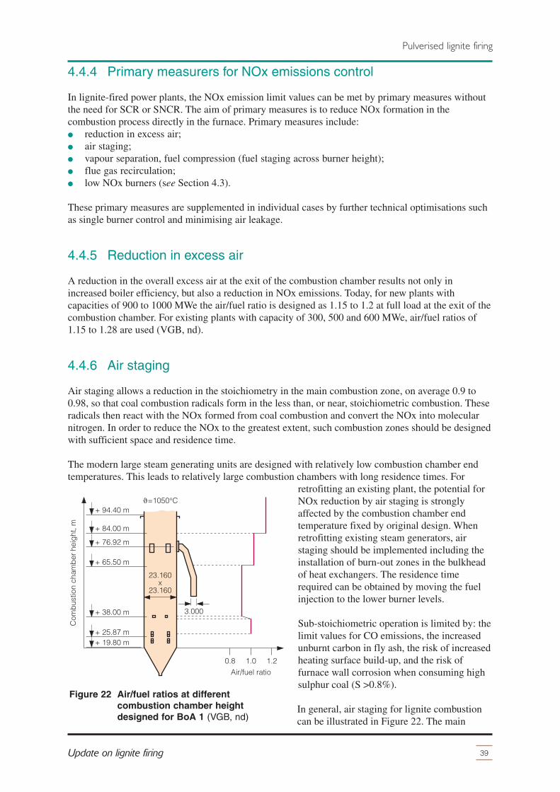
4.4.4 Primary measurers for NOx emissions control
In lignite-fired power plants, the NOx emission limit values can be met by primary measures withoutthe need for SCR or SNCR. The aim of primary measures is to reduce NOx formation in thecombustion process directly in the furnace. Primary measures include:� reduction in excess air;� air staging;� vapour separation, fuel compression (fuel staging across burner height);� flue gas recirculation;� low NOx burners (see Section 4.3).
These primary measures are supplemented in individual cases by further technical optimisations suchas single burner control and minimising air leakage.
4.4.5 Reduction in excess air
A reduction in the overall excess air at the exit of the combustion chamber results not only inincreased boiler efficiency, but also a reduction in NOx emissions. Today, for new plants withcapacities of 900 to 1000 MWe the air/fuel ratio is designed as 1.15 to 1.2 at full load at the exit of thecombustion chamber. For existing plants with capacity of 300, 500 and 600 MWe, air/fuel ratios of1.15 to 1.28 are used (VGB, nd).
4.4.6 Air staging
Air staging allows a reduction in the stoichiometry in the main combustion zone, on average 0.9 to0.98, so that coal combustion radicals form in the less than, or near, stoichiometric combustion. Theseradicals then react with the NOx formed from coal combustion and convert the NOx into molecularnitrogen. In order to reduce the NOx to the greatest extent, such combustion zones should be designedwith sufficient space and residence time.
The modern large steam generating units are designed with relatively low combustion chamber endtemperatures. This leads to relatively large combustion chambers with long residence times. For
retrofitting an existing plant, the potential forNOx reduction by air staging is stronglyaffected by the combustion chamber endtemperature fixed by original design. Whenretrofitting existing steam generators, airstaging should be implemented including theinstallation of burn-out zones in the bulkheadof heat exchangers. The residence timerequired can be obtained by moving the fuelinjection to the lower burner levels.
Sub-stoichiometric operation is limited by: thelimit values for CO emissions, the increasedunburnt carbon in fly ash, the risk of increasedheating surface build-up, and the risk offurnace wall corrosion when consuming highsulphur coal (S >0.8%).
In general, air staging for lignite combustioncan be illustrated in Figure 22. The main
39Update on lignite firing
Pulverised lignite firing
=1050°C
1.2
Air/fuel ratio
Com
bus
tion
cham
ber
hei
ght
, m
+ 94.40 m
1.00.8
23.160x
23.160
+ 84.00 m
+ 76.92 m
+ 65.50 m
+ 38.00 m
+ 25.87 m+ 19.80 m
3.000
Figure 22 Air/fuel ratios at differentcombustion chamber heightdesigned for BoA 1 (VGB, nd)

burner region is operated with an air/fuel ratio of about 0.9–0.98 (including vapour burners whereavailable). The OFA (overfire air) 1 increases the air ratios to about 1.0. The distance between themain burners and OFA 1 ensures a sub-stoichiometric range for NOx reduction. The OFA 1 starts toreduce the excess CO. The previous operating experience showed that in the main combustion zonewhere the combustion temperature is around 1000–1300°C, there is an increasing risk of hightemperature corrosion under reducing conditions if the sulphur content in lignite is greater than 0.8%.This high temperature corrosion is caused by H2S.
The distance between the main burners andlowest OFA must be sufficiently great so thatcombustion of the volatiles is more or lesscompleted. If the lowest burn -out air level is inan area where the burn-out of volatiles in thesub-stoichiometric range is not complete, theremaining radicals are then oxidised byaddition of oxygen and the reduction of NOxis terminated prematurely causing an increasein emissions.
The adjustment of air/fuel ratio is primarilydependent on the combustion and ashingbehaviour of the lignite. Figure 23 shows theair/fuel rations designed for a BoA unit burningHambach lignite and Garzweiler lignite.
The OFA increases the total air ratio in stages.The distribution of OFA levels must alsoensure sufficient residence time.
The air jets for combustion air should bearranged so that the total cross-sectional area iscovered. This is crucial in order to minimiseunburnt matter and for CO combustion(VGB, nd).
4.4.7 Fuel compression, vapour separation
In order to reduce NOx emissions from existing lignite plants, changes to the existing firing systemscan be made. For retrofitting existing lignite-fired units, there are three feasible firing systems forprimary NOx emissions control (RWE Power International, 2006):� Direct combustion with reduced burner row height resulting in a more concentrated fuel area and
separated air staging. This concept is appropriate for large steam generators with long residencetimes in the combustion chamber.
� Direct combustion with reduced burner row height resulting in a more concentrated fuel area andseparated air staging combined with additional flue gas recirculation. This concept is the mostvariable and can be used for all sizes of steam generators. In flue gas recirculation, cold flue gasis recirculated from downstream of the ESP and injected into the furnace via separate nozzlesarranged above the burner row. This increases the mixing of the reactants even in the case ofshort residence times. Combustion burn-out is delayed by the addition of the flue gas.
� Modified vapour burner concept. Direct combustion with a vapour separator downstream of themill to divide the fuel/carrier gas mixture to the main and vapour burners and air staging acrossthe combustion chamber height.
40 IEA CLEAN COAL CENTRE
Pulverised lignite firing
=1010°C
50
40
30
20
10
0
Air/fuel ratio in the furnace, m
Furn
ace
heig
ht, m
60
70
1.21.00.8
80
90
1.10.9
design for Hambach coaldesign for Garzweiler coal
26.040x
26.040
Figure 23 Air/fuel ratios at different furnaceheight for two lignite coals(Habermann and others, 2004)
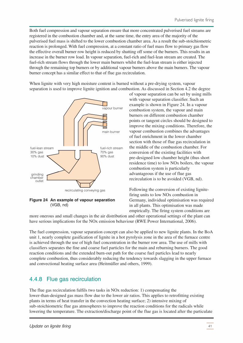
Both fuel compression and vapour separation ensure that more concentrated pulverised fuel streams areregistered in the combustion chamber and, at the same time, the entry area of the majority of thepulverised fuel mass is shifted to the lower combustion chamber area. As a result the sub-stoichiometricreaction is prolonged. With fuel compression, at a constant ratio of fuel mass flow to primary gas flowthe effective overall burner row height is reduced by shutting off some of the burners. This results in anincrease in the burner row load. In vapour separation, fuel-rich and fuel-lean stream are created. Thefuel-rich stream flows through the lower main burners whilst the fuel-lean stream is either injectedthrough the remaining top burners or by additional vapour burners above the main burners. The vapourburner concept has a similar effect to that of flue gas recirculation.
When lignite with very high moisture content is burned without a pre-drying system, vapourseparation is used to improve lignite ignition and combustion. As discussed in Section 4.2 the degree
of vapour separation can be set by using millswith vapour separation classifier. Such anexample is shown in Figure 24. In a vapourcombustion system, the vapour and mainburners on different combustion chamberpoints or tangent circles should be designed toimprove the mixing conditions. Therefore, thevapour combustion combines the advantagesof fuel enrichment in the lower chambersection with those of flue gas recirculation inthe middle of the combustion chamber. Forconversion of the existing facilities withpre-designed low chamber height (thus shortresidence time) to low NOx boilers, the vapourcombustion system is particularlyadvantageous if the use of flue gasrecirculation is to be avoided (VGB, nd).
Following the conversion of existing lignite-firing units to low NOx combustion inGermany, individual optimisation was requiredin all plants. This optimisation was madeempirically. The firing system conditions are
more onerous and small changes in the air distribution and other operational settings of the plant canhave serious implications for the NOx emission behaviour (RWE Power International, 2006).
The fuel compression, vapour separation concept can also be applied to new lignite plants. In the BoAunit 1, nearly complete gasification of lignite in a hot pyrolysis zone in the area of the furnace centreis achieved through the use of high fuel concentration in the burner row area. The use of mills withclassifiers separates the fine and coarse fuel particles for the main and reburning burners. The goodreaction conditions and the extended burn-out path for the coarse fuel particles lead to nearlycomplete combustion, thus considerably reducing the tendency towards slagging in the upper furnaceand convectional heating surface area (Heitmüller and others, 1999).
4.4.8 Flue gas recirculation
The flue gas recirculation fulfils two tasks in NOx reduction: 1) compensating thelower-than-designed gas mass flow due to the lower air ratios. This applies to retrofitting existingplants in terms of heat transfer in the convection heating surface; 2) intensive mixing ofsub-stoichiometric flue gas atmospheres to improve the reaction conditions for the radicals whilelowering the temperature. The extraction/discharge point of the flue gas is located after the particulate
41Update on lignite firing
Pulverised lignite firing
fuel-lean stream30% gas10% dust
fuel-rich stream70% gas90% dust
vapour burner
main burner
grindingchamber
outlet
recirculating conveying gas
Figure 24 An example of vapour separation(VGB, nd)

control device and before the FGD. The undesulphurised flue gas is transported back into the furnacebetween the burners and the OFA 1 using an additional fan.
Flue gas recirculation is normally used only for existing plants with short residence time, where theimplementation of air staging and lower air/fuel ratio would cause problems as a result of combustionlosses and CO formation. The potential reduction in NOx emissions is approximately 15-30 mg/m3 atabout 10–15% flue gas recirculation.
Flue gas recirculation can help to reduce the furnace exit gas temperature. Thermally, a flue gasrecirculation system is necessary if the heat transfer balance between radiative and convective heattransfer must be manipulated for specific operating conditions. However, the frequent lead-in andshut-downs of the recirculation fan lead to severe corrosion in the entire piping system due tooperation under acid dew point, and therefore air-flushing and -purging are required. The increaseddemand on the induced draft and recirculation fan as well as a greater flue gas loss in the boilerreduces the net unit efficiency. Furthermore, the flue gas recirculation system is operated underpositive pressure. Accordingly, high standard technical design to avoid flue gas leaks is required.Leaks leads to acid condensation in the insulation and other consequential damages. Because of thesedisadvantages, flue gas recirculation systems are not usually employed when NOx emission valuescan be met with other primary measures (VGB, nd)
4.4.9 Heating surface cleaning system
The combustion chamber requiresstate-of-the-art cleaning devices, especiallywhen lignite with a high slagging tendency isburned. A combination of water lances andwater-jet blowers can be used. The latter areused in the main burner area, since experiencefrom utility scale operation has shown thatwater-jet blowers are advantageous in thoseareas. The cleaning concept and the cleaningstrategy can be adapted in accordance to thespecial requirements of the type of ligniteused. Figure 25 shows the arrangement ofwater-jet sprayers for the 675 MWe Unit Rlignite-fired steam generator at Boxberg PowerPlant (Germany). The water-jet sprayers arecombined with water counter-flow fans in thecombustion chamber or the combustion beltarea.
Figure 26 presents the cleaning arrangement for a BoA unit. The water lance-type blowers in thecombustion chamber are spread over five layers with four blowers each in the radiation chamber andtwo additional water lance-type blowers in the area of the furnace hopper. The installation locations ofthe water lance-type blowers are marked as red points in Figure 26. The cleaning medium is servicewater with a pressure of approximately 2.5 MPa upstream of the blower. In addition to the waterlance-type blowers, water-jet blowers working with a water pressure of 1.2 MPa are used in the burnerrow area. The arrangement of these sootblowers are shown as blue circles in Figure 26.
Long retractable sootblowers are used for cleaning of the superheater bank-type heating surfaces andeconomiser and reheater 1 are equipped with helical sootblowers. Their range of cleaning is illustratedin Figure 27. Each space between the tube banks is fitted with sootblowers. Superheated steam fromthe reheater is used as blowing medium. The sootblowers for all convective heating surfaces are
42 IEA CLEAN COAL CENTRE
Pulverised lignite firing
WB
WB
WB
SL
SL
WLB
WB
WB WB
SL
WLBWB
SL
SLKA
SL+18.285 m
funnel
Figure 25 The arrangement of water-jetsprayers for the lignite-fired boiler atBoxberg’s Unit R (Mandel andSchettler, 2007)

arranged on both sides. The blowing pressurefor the sootblowers is approximately 2.5 MPafor the lance-type sootblowers and 1.2 MPafor the helical sootblowers.
The long retractable sootblowers are equippedwith highly efficient nozzles which have abetter cleaning effect than conventionalnozzles with regard to the target blowingpressure. A further development of thecurrently available sootblowers with improvedcleaning efficiency for applications of difficultcoal is currently being pursued intensively.
An expert system for optimised sootblowingcan be used. With this system, the individualsootblower is controlled as a function of theheating surface efficiencies and minimumblowing intervals. This ensures the designedheating surface efficiencies are maintainedwith minimal blowing. In the combustionchamber, in order to maintain the heatabsorption of the wall heating surfaces under
all operating conditions, the local heat flux density is monitored by means of sensors. If the heatflux density falls below a certain value, the surface assigned to the sensor will be cleaned(Habermann and others, 2004).
4.5 Materials
The various components of the boiler experience a range of temperatures, pressures and corrosiveatmospheres, and oxidation conditions. For a modern large SC steam generating unit, due to the highsteam conditions and the high weight load, materials used must withstand high temperature andpressure in oxidising and corrosive environments in accordance with their application. A practicallimitation to the higher steam pressure and temperatures that can be achieved in a boiler is the
43Update on lignite firing
Pulverised lignite firing
22 water lance-type blowers5 levels x 4 blowers2 blowers for the furnace hopper
OFA 2FGR
+ 87 m furnace exit
52 water wall blowersin burner belt
+ 0 m
OFA 1
water lance blowers
26.040 x 26.040
Figure 26 Arrangement of sootblowers infurnace (Habermann and others, 2004)
1350
1500
1500
440
660
Hei
ght
of t
ube
ban
ks, m
m1350
1350
Tran
sver
sal s
pac
ing
, mm
RH2.2st = 240
SH4st = 480
SH2st = 480
RH2.1st = 480
Figure 27 Arrangement of sootblowers in the convective part (Habermann and others, 2004)

availability of boiler materials that can withstand these elevated conditions over an acceptable servicelife. Currently, the best commercially available steels allow the construction of boiler plant for steamconditions of 30 MPa/600ºC/620ºC for a wide range of coals, even those producing an aggressivelycorrosive flue gas. The range of alloys necessary to best meet the design demands of SC steamgenerators covers the simple carbon manganese (CMn) steels, low alloy steels, advanced low alloysteels, the 9–12Cr martensitic family and the austenitic range with chromium varying from 18% to inexcess of 25% (DTI, 2006).
As superheater tubes must be designed to operate at temperatures ~35ºC above the live steamtemperatures, for steam temperatures up to ~580ºC, the metal temperature will be ~615ºC and low-alloy steel tubes such as T22 and T23 may possess adequate creep strength. However, not only do theadvanced steam parameters for supercritical plant impose higher stresses on the superheater tubes,they also increase the potential rates of both fireside and steam-side corrosion. Medium-chromium(Cr) steels such as X20 can be used at these temperatures or alternatively, for corrosive coals or highertemperatures, more expensive austenitic steels such as T316 and T347 can be used.
The layout and design issues for reheater banks are similar in principle to those of the superheaterbanks, in particular with reference to materials and temperature limits. However, there is more scopewith the reheater to increase temperatures or adopt novel designs because the reheater pressure ismuch lower and so the tubes are under much less stress. In addition, the reheater is normally situatedbehind the superheater in a region of cooler gas flow. An additional 20ºC is typically achievable inreheater steam temperatures for the same material constraints. The current maximum boiler reheatoutlet steam temperature is 610ºC for lignite (PowerClean, 2004).
In thick-sectioned components such as steam pipes and headers, ferritic steels, from carbon steel up to12% Cr X20CrMoV121 (Mo: molybdenum; V: vanadium), have been used for steam conditions of25 MPa/560ºC. Here, the steam lines are normally now manufactured from X20CrMoV121. Materialswith even higher creep strength will be needed for thick-section components under more advanced steamconditions and P91/T91/F91 are suitable for such use up to ~30 MPa/580–600ºC (PowerClean, 2004).Figure 28 shows the materials used for heating surfaces of Mitsui Babcock’s SC boilers.
Figure 29 illustrates the alloys selected for the heating surfaces of a BoA steam generator. The heating
44 IEA CLEAN COAL CENTRE
Pulverised lignite firing
Figure 28 Advanced supercritical tubematerials (30 MPa/600°C/620°C)(DTI, 2006)
9
4
5
8
6
8
7
3
11
10
1 2
Refer-ence
Heatingsurface
MaterialDesigntemp, °C
1 Platen SHSA 213 TP347H/TP310HCbN/T92*
640
2 Final SHSA 213 TP347H/TP310HCbN/T92*
650
3 Final RHT22/T91/TP347H/TP310HCbN/T92*
680
4 Prim SH SA 213 T91 550
5 Prim SH inlet SA 213 T23 530
6 RH inlet SA 210C 470
7 RH SA 213 T12 540
8 Economiser SA 210C 375
9 Water wall SA 213 T12/T23 515
10 Furnace roof SA 213 T23 510
11 Rear cage SA 213 T23 510
* SA213 T92 used for outlet tube stub connections

surfaces are coloured to reflect the materialselection. The colour assignment of theselected materials is shown on the left and theheader materials are listed at the bottom of thefigure. The economiser is made completely of16Mo3. Reheater 1 consists of the materials16Mo3, 13CrMo4-5, 7CrMoVTiB10-10 andX20CrMoV11-1. With chromium content of12% the material X20CrMoV11-1 has highercorrosion resistance than 7CrMoVTiB10-10and is therefore chosen for the reheater outlet.The material used for the superheater 2supporting tube screen is HCM12, which is amartensite with 12% of chromium and hencehas higher strength values thanX20CrMoV11-1. The last two superheatersand the reheater end stage are made ofaustenite. For reasons of corrosion protection,the austenite material has a mean chromiumcontent of at least 18%.
Due to the high steam temperatures and thehigh axial loads, the material 7CrMoVTiB10-10 is employed as a wall material at theend of the evaporator spiral and in the vertical
tubing part of the membrane wall. The supporting tubes are also made of this material for the samereason.
The separator and vessel are made of P91. For the superheaters and the reheaters, from the reheater 1outlet onwards, martensitic 9% chromium steels P91, E911 and P92 are used as header materials.Whether E911 or P92 would be selected for the superheater 3 and live steam outlet header woulddepend on the final strength values of these materials (Habermann and others, 2004).
There have been a number of concerted R&D programmes dedicated to development of advancedhigh-temperature materials that allow the adoption of even higher steam conditions for PCC units. Forexample, the AD700 project in Europe, aims at the construction and operation of a 500 MW USC PCCdemonstration plant (called 50plus) with a net efficiency of over 50% and steam conditions of35 MPa/700ºC/720ºC. It has a strong focus on development of nickel-based alloys for USC steamconditions of >37.5 MPa/700ºC through testing work in its COMTES700 testing facility. A similarprogramme funded by the US DOE is evaluating materials to achieve steam conditions of35.2 MPa/760ºC/760ºC/760ºC. The UltraGen II programme is one of EPRI’s UltraGen Initiative projectswhich aims at a 750 MW 1300°F (704.4°C) Series USC plant design. In 2008, EPRI published theresults from Phase I of an engineering and economic evaluation for such plants fired with subbituminouscoal. Similar results for lignite and bituminous coal will be reported in Phases II and III of the study. Thereport concluded that the high-nickel alloys used in the boiler and steam turbine necessary for achievingthese higher steam conditions were at an advanced stage of development and were expected to beavailable to support construction of an UltraGen II demonstration plant within a few years (Dong, 2011).
4.6 Turbine system
The basic construction of single reheat large steam turbines for coal-fired power plant was establishedover 30 years ago. This construction, designed originally for operating at conventional steamconditions, has achieved very high standards of reliability, availability and operational flexibility
45Update on lignite firing
Pulverised lignite firing
headers
15NiCuMoNb5-6-4
16Mo3 (in)P91 (out)
P91 (in)E911/P92 (out)
P91 (in)E911 (out)
P91 (out)
E911 (in)E911/P92 (out)
16Mo3
X20CrMoV11-1
7CrMoVTiB10-10
Austenite (Cr≥18%)
13CrMo4-5
tubes
eco
RH1
SH3
RH2
SH4
SH2
HCM12
Figure 29 Alloys selected for the heatingsurfaces of BoA boilers (Habermannand others, 2004)

through continuing development and feedback of operating experience. Today, turbo-sets for SC andUSC steam power plants are available for gross power outputs from 600 to 1200 MWe per unit. Atypical turbo-set comprises three separate turbine modules operating at different pressure andtemperature levels: high pressure turbine (HP), intermediate pressure turbine (IP) and, depending onthe cooling water conditions, one, two or three low pressure turbines (LP).
Nearly 2 percentage points of the efficiency gain in recently built large lignite-fired power plantscomes from advances in steam turbine design. In today’s state-of-the-art HP and IP turbines, all
internal stationary components are beingreplaced with a single, fully integral casing.The unique features of the casing designprovide the control of the inner casing’sthermal distortion, resulting in maintainingdesigned clearances and obtaining the highestpossible efficiency at running speed.
R&D in the field of steam turbine blading hasaccelerated rapidly in recent years through theuse of CFD models. The modern HP and IPblade paths are designed using advancedairfoil shape (see Figure 30), overall bladepath thermodynamic optimisation andenhanced sealing to provide improved efficientperformance for the available space. Thisadvanced airfoil design has a considerableadvantage over the previous generation of thetypical parallel-sided airfoil, allowing theairfoil shape to be enhanced to the varyingsteam conditions between the base and tip ofthe blade.
The drum-type HP/IP blade constructionfeatures an integrally shrouded blade designconcept. The integral shrouds provide twobasic functions: first, they form acircumferential steam path boundary allowingefficient seal designs to be utilised; andsecond, they provide individual blade tipsupport between neighbouring blades in eachblade row.
The seals for the HP, IP and LP dummypistons are comprised of a combination ofboth spring back and retractable sealsegments. Retractable seals provide smallradial clearances during operation (closedposition) and large radial clearances in theopen position. These types of seals minimisewear and optimise performance of themachine (Cheski and others, 2005; Quinkertzand others, 2008; DTI, 2006). Examples ofadvanced turbine designs are shown inFigure 30.
46 IEA CLEAN COAL CENTRE
Pulverised lignite firing
Figure 30 Examples of efficiency-increasingmeasures related to steam turbine(Cheski and others, 2005)
a) Retractable seal
b) Integrally shrouded tee-root blade
c) Dimensional airfoil shape blades

4.7 Waste heat recovery and utilisation
The waste heat recovery and utilisation systems ensure that the highest possible amount of the heatarising in the combustion of lignite is integrated into the process and exploited in power generation.Figure 31 shows the waste heat recovery and utilisation system used in BoA 1 plant. At full load theflue gases produced by the lignite combustion leave the furnace at a temperature around 1050ºC. Afterhaving passed the convection heating surfaces arranged above the furnace, the flue gases are conveyedin the downward open pass to the two parallel rotary air heaters and to the air heater bypasseconomiser (lubeco) which is also arranged parallel to these two rotary air heaters. The flue gases arejoined underneath the two rotary air heaters or at the side underneath the lubeco and then conveyed tothe two electrostatic precipitators, the two flue gas coolers and then to the FGD system.
The flue gas coolers are arranged upstream of the FGD plant for flue gas heat recovery. The flue gascoolers reduce the flue gas temperature from 160ºC to the minimum temperature of 100ºC for aneffluent-free operation of the FGD plant and keeps this temperature constant over all operatingconditions. This arrangement utilises the low grade heat in the cycle process leading to improvedenergy efficiency. Approximately 80 MJ/s of heat is recovered and transferred to the process of steamgeneration through the use of the flue gas coolers. In the first stage the heat is recovered via a watercycle in a feedwater/air heater. As the quantity of heat flux to be absorbed by the combustion air in therotary air heater in the second preheating stage is now reduced, a part of the flue gas heat can beutilised for the preheating of feedwater and condensate. About one-third of the flue gas, with atemperature of around 350ºC, is led through the lubeco which is arranged in bypass to the rotary airheaters, where it dissipates the heat in the first section to a partial stream of the feedwater in parallelwith the HP heaters as shown in Figure 31.
In the second section, steam is generated by natural circulation for heating the penultimate LP heater.
47Update on lignite firing
Pulverised lignite firing
LP-heater 1-6
123456
HP-heater 1-3
123
main condensate
condenser
LP air heaterbypass economiser
coolingtower
flue gas cooler
ESP
air heater bypasseconomiser ash removal
2/3
1/3
HP air heaterbypass economiser
flue gasdesulphurisation
water air heater
air heater
steam generator
Figure 31 Extensive heat transfer systems for higher overall efficiency (RWE, 2011)

The flue gas temperature downstream of the air heater bypass is 160ºC. With this arrangement, lesssteam needs to be extracted from the turbine for condensate and feedwater preheating (Heitmüller andothers, 1999).
The waste heat recovery and utilisation system used in BoA 1 plant contributes to more than0.9 percentage points of total net unit efficiency gain.
4.8 Impact of lignite characteristics
Coal type and quality affect the design, operation, performance of the plant and hence its capital andoperating costs. The main properties of a lignite coal that affect firing system design include:� heating value;� ash content, ash characteristics;� moisture content;� volatile matter;� grindability (Hardgrove Grindability Index).
Considerable variation in the lignite properties may require an adjustment of the operating conditionsof the firing system and the mills.
The milling, drying and firing systems applied to the BoA Plus power plant are developed inaccordance with the quality of the German lignite coals burnt at the plant. When the BoA/BoA Plustechnologies are employed to burn different lignite coals, adjustments and optimisations of thesesystems and in boiler design will be required depending on lignite characteristics. RWE recentlycarried out a technical and economical analysis of applications of the BoA plant concept boiler designto Greek lignites. The characteristics of three Greek lignites and a German lignite are compared inTable 6. It can be seen from Table 6 that Greek lignites have much higher ash contents compared tothe German Rhenish lignite. The moisture content of Greek Florina lignite is lower than that ofRhenish lignite whilst the moisture content of Greek Drama and Ptolemäis lignites are comparable tothat of Rhenish coal. Consequently, the Greek lignites have lower heating values than that of Rhenishlignite. The drying energy of a coal, calculated based on the coal moisture content and heating value,is an indication of the energy required to dry the coal. As shown in Table 6, the drying energy ofDrama and Ptolemäis coal is considerably higher compared to Rhenish coal. The drying energy ofDrama coal is twice as high as that of Rhenish coal and about 30% of the fuel energy is needed fordrying the coal. As a result, optimised design and special operating conditions for milling, drying andburner systems are required for Drama and Ptolemäis coal. The drying energy of Florina iscomparable to the value of Rhenish coal and there should be no problem for the drying process.
48 IEA CLEAN COAL CENTRE
Pulverised lignite firing
Table 6 Comparison of Greek and German lignites (RWE Power International, 2006)
Rhenish Drama Ptolemäis Florina
Water content, % 53.0 57.8 51.1 37.4
Ash content, % 5.0 16.1 17.3 27.2
Net calorific value, MJ/kg 8.70 4.38 5.36 7.89
Flue gas mass, kg/MJ 0.54 0.69 0.62 0.51
Specific coal mass, kg/MJ 0.115 0.228 0.186 0.127
Ash mass, g/MJ 5.74 36.8 32.2 34.5
Boiler efficiency, % 93.0 87.0 88.6 89.7
Auxiliary power consumption, % 5.0 6.0 6.0 6.0
Unit net efficiency, % 43.3 39.3 40.0 40.5

However, Florina coal contains a higher content of xylite elements, which may cause problems in themilling system in achieving the required grinding fineness and problems in the furnace because xyliteparticles need a longer burn-out time.
Another parameter that affects the boiler design is the mass flow rate of flue gas. The mass flow ratesshown in Table 6 are determined by the fuel heating value and based on 10% excess air. Due to the highmoisture content and low heating value, the Drama and Ptolemais coal have significantly higher flue gasmass flow rate whilst Florina coal has a similar flue gas mass flow rate compared with that of Rhenishcoal. The increase in the specific flue gas mass flow rate results in a larger absolute mass flow of flue gasin the boiler for the same fuel heat consumption. Therefore, the dimensions of the boiler have to beincreased and the heat transfer between the flue gas and boiler heating surfaces has to be modified. Thehigher volume of flue gas also has an influence on the firing system and the FEGT.
A stable flame can be achieved by optimised burner design and the boiler tube heating surface must beincreased in order to absorb the heat of the flue gas and decrease the waste gas temperature.
The higher flue gas mass flow of the Greek lignite requires a different design of burner layout toensure an adequate flame development and behaviour in order to achieve stable firing and sufficientNOx reduction. This behaviour depends on the flue gas and air velocity leaving the burner and thecoal to flue gas ratio importing the firing heat to the burner mouth. The relation between these items isvery important for the ignition and burning of the lignite. Due to the higher coal-flue gas ratio used,and other factors such as greater coal mass flow, the burner areas must be increased to ensure equalvelocities. This will result in an increase in the electrical power demand of the induced draft fans,leading to a decrease in net boiler efficiency. The capital cost will also increase, due to theenlargement of the firing system, the heating surfaces and the boiler dimensions.
It is evident from Table 6 that a boiler burning Drama coal will have larger specific fuel mass flow,nearly twice as much as that of a boiler burning Rhenish coal. This directly affects the milling systemand the coal handling plant, increasing the capacities and therefore the capital cost. The powerconsumption of the drive motors will also increase resulting in a reduction in the net efficiency of thepower plant.
The high ash content of all three Greek lignites means higher ash mass flow leading to an ashhandling plant three times larger then that for the Rhenish coal. The high ash mass flow also results inan increase in the unburnt carbon in the furnace bottom ash and in the fly ash. In addition, heatdissipation occurs due to the increased mass flow of discharged ash. Consequently, the boilerefficiency is reduced and the auxiliary power consumption is increased as shown in Table 6, leading tohigher capital and operating costs (REW Power International, 2006).
Further technical investigations are necessary in order to apply the BoA technologies to the Greeklignites and to lignite coals from other parts of the world, especially for coals with rather differentcharacteristics from that of the Rhenish lignite.
4.9 Case study: BoA 2&3
The RWE’s Neurath Power Station units F and G, also referred to as BoA 2 and 3, have a gross capacityof 1100 MWe each (1050 MWe net) and a net efficiency of over 43%, similar to that of Niederaussemunit K (BoA 1). The high efficiency of the BoA 2 and 3 units at Neurath can be ascribed to:� the steam conditions (600/605ºC); the steam turbine technology; the nine-stage feedwater
preheating system;� the maximisation of waste heat recovery from the flue gas, � minimisation of auxiliary power needs, for example, through use of turbine driven feedwater
pumps.
49Update on lignite firing
Pulverised lignite firing

50 IEA CLEAN COAL CENTRE
Pulverised lignite firing
Table 7 Key data for BoA 2 and 3 (Elsen and Fleischmann, 2008)
Owner/operator RWE Power AG
Fuel domestic lignite
Cooling system cooling tower with natural draught
Installed capacity, MWe 1100 (gross), 1050 (net)
Net efficiency, % >43
Steam generator
Type once-through, tower
Steam flow, t/h 2870 (2960 maximum)
Steam pressure, MPa 27.2 (28.04 maximum)
Steam temperature, °C 600
Furnace capacity, MWt 2392 (2800 maximum)
Raw lignite input (guarantee lignite), t/h 820 (1326 maximum)
Steam turbine
Type STF 100
Number of modules (casings) 4
Steam pressure, MPa 25.9
Steam temperature – inlet/reheat, °C 595/604
Speed, rpm 3000
Generator
Type GIGATOP
Rating, MVA 1333
Power factor 0.825
Frequency, Hz 50
Terminal voltage, kV 27
Excitation system static excitation system
Cooling system hydrogen plus water
Condensing plant
Circulating water temperature, °C 18.2
Condenser pressure, kPa 4.8
Tube material stainless steel
Feedwater heating plant
Number of feedwater preheating stages 9
Number of feedwater heaters 8
Number of feedwater deaerating tanks 1
Feedwater inlet temperature, °C 292
Main pumps
Condensate extraction pumps, % 3 x 50
Feedwater pump1 x 100% main turbo driven feedwater pump plus
2 x 40% start-up motor driven feedwater pump
Circulating water pumps, % 2 x 50
Polishing plant yes
Main transformers
Rated output, MVA 2 x 1100 (per unit)
Primary/secondary, kV 420/27
Standby transformer
Rated output, MVA 90/45/45
Primary/secondary, kV 110/10.5/10.5
The key data for BoA 2 and 3 are summarised in Table 7.

The units burn lignite that is supplied by RWE’s own local opencast mines at Garzweiler andHambach. The lignite mills pulverise the lignite and, to lower its high moisture content (48–60%), dryit using hot flue gases taken from the furnace. Next, together with heated air from the flue-gas airheater, the pulverised lignite is blown into the combustion chamber of the steam generator.
The boilers are of once-through, single passtype each having a capacity of 2392 MWth(2800 MWth maximum). They are the largestlignite-fired boilers in the world, with thehighest steam mass flows, supercritical steampressures and steam temperatures ever reachedfor lignite. The boiler dimensions and othertechnical data are shown in Table 8.
The process flow of the BoA 2 and 3 is shownin Figure 32. The firing system and the burnerarrangement implemented in BoA 2 and 3have been described in detail in Section 4.4.1.The lignite combustion temperature is about1200ºC. The hot flue gas that emerges duringcombustion flows through the steam generatorfrom bottom to top. In the process, it transfers
heat to the outer walls, which consist of tubes, and to the tube banks suspended in the flue-gas flow.Heated feedwater flows through these tube systems and is evaporated and superheated. The detaileddescriptions of the thermal design of the BoA boilers can be found in Section 4.4.3.
After passing through the topmost bank of heating surfaces, the flue gas is redirected to the downwardopen-pass duct and distributed across the two flue-gas air heaters to preheat the combustion air. Afterflowing through these heat exchangers, the flue gas (cooled from about 350ºC to 160ºC) is conductedin two parallel lines to flue gas cleaning systems. The latter consist of electrostatic precipitation forparticulate removal, followed by FGD. A further portion of the remaining flue-gas heat is removedfrom the flue gas before it is fed into the FGD plant via flue gas coolers and transferred via aheat-transfer cycle to a part-flow of the condensate in the feedwater heating section. This lowers theflue-gas temperature to 125ºC before it enters the FGD system, which employs polypropylene andconcrete for the scrubber wall materials.
Combustion is subject to constant monitoring and adjustment of the lignite and air feed, so that it isoptimised and NOx production minimised. The legally prescribed emission limit values for NOx(200 mg/m3) can be easily met by these combustion measures alone, without additional postcombustion de-NOx systems.
The main steam produced by the steam generator has a pressure of 27.2 MPa and a temperature of600ºC and is initially expanded to 5.87 MPa in the turbine’s high-pressure section, where thetemperature falls to 356ºC. This steam is conducted back to the steam generator and superheated again(reheated) to 605ºC. In the intermediate- and low-pressure sections the steam expands to the pressureof 4.8 Pa prevailing in the condenser, where it is precipitated as water. The cooling water is re-cooledin the cooling tower by falling as rain in continuous contact with cooling air. The cooling air requiredfor this in the energy-efficient natural-draught tower necessitates the tower height of around 170 m.
The cooling water that evaporates during re-cooling, and the cooling water that must be discharged toavoid excess concentrations of salt, has to be replaced on a continuous basis. The make-up water isprimarily from the Frimmersdorf power plant, which is treated there before it is deployed in Neurath.Alternatively, treated water from Niederaussem can be used.
51Update on lignite firing
Pulverised lignite firing
Table 8 Technical data of BoA 2 and 3(Elsen and Fleischmann, 2008)
Firing thermal capacity, MWth 2392 (max 2800)
Lignite feed, t/h 820 (max 1300)
Main steam 27.2 MPa/600°C
Hot reheat steam 5.5 MPa/605°C
Total dimensions, m 170 x 100 x 100
Dimension of boiler, m 142 x 26 x 26
Heating surface, m2 146,000

52 IEA CLEAN COAL CENTRE
Pulverised lignite firing
coal
del
iver
yb
y ra
il
gyp
sum
utili
satio
nto
out
fall
ditc
h
wag
onun
load
ing
mak
e-up
wat
er fr
omFr
imm
ersd
orf/N
eura
thp
ower
pla
nts
gyp
sum
stor
e
exis
ting
ser
vice
and
rai
n w
ater
treat
men
t pla
nt
tota
ld
emin
eral
isat
ion
pla
nt
settl
ing
pon
d
wet
ash
bin
slot
bot
tom
bin
tran
sfor
mer
flue
gas
des
ulp
huris
atio
nsy
stem
(FG
D)
ind
uced
dra
ft fa
n
turb
og
ener
ator
coal
bin
air
heat
erstea
m g
ener
ator
ligni
tem
ills
soun
dco
ntro
lw
all
cond
ense
r
turb
ine
stea
m p
ipes
flue
gas
cool
er
dry
ash
bin
dus
tco
llect
ion
open
pas
s
flue
gas
dis
char
ge
feed
wat
er ta
nk
low
pre
ssur
ep
rehe
ater
forc
ed d
raft
fan
mai
n co
nden
sate
pum
ps
hig
hp
ress
ure
pre
heat
er
feed
pum
ps
cond
ensa
tep
olis
hing
pla
nt
cond
ensa
teb
oost
erp
ump
s
wet
sla
gex
trac
tor
filte
rco
mb
ustio
n ai
r
fuel
oil
pum
p
fuel
oil
tank
cool
ing
wat
erd
emin
eral
ised
wat
er
dis
char
ge
rain
wat
er
som
e us
ed in
pow
er p
lant
pro
cess
serv
ice
wat
er
ash
tran
spor
tatio
n to
dum
pin
g g
roun
d
ash
wet
ting
to d
ump
ing
gro
und
in o
pen
cas
t min
e
long
dis
tanc
e as
h co
nvey
or
limes
tone
slur
ry
pul
veris
edlim
esto
nesi
lo
circ
ulat
ing
wat
er ta
nk
gyp
sum
dew
ater
ingst
eam
feed
wat
er/c
ond
ensa
ted
emin
eral
ised
wat
erco
olin
g w
ater
fuel
boi
ler
ash
flue
gas
was
te
cool
ing
tow
er
Figure 32 Schematic of the BoA 2 and 3 (Elsen and Fleischmann, 2008)
53Update on lignite firing
Pulverised lignite firing
At Neurath, the steam turbines, each rated at 1100 MWe, are of the Alstom STF100 type. Theyemploy fully flow optimised blading. A compact four casing configuration is employed: HP, IP andtwo LP (whereas at Niederaussem there is a three-casing LP). The two-casing four-flow low pressureturbine stage is made possible through the use of titanium 1.408 m last-stage blades – the longestlast-stage blades currently offered on the world market, providing an exhaust cross-section of 13.2 m2.The compactness of the steam turbine contributes to reduced construction costs.
In addition to reduced CO2 emissions due to the higher efficiencies, the BoA units will also achievespecific SO2, NOx and particulates emission levels below the limits specified in the German ordinanceon large combustion plants: SO2 – 200 mg/m3 and a desulphurisation rate of >85%; NOx –200 mg/m3; CO – 200 mg/m3; and particulates – 20 mg/m3.
4.10 Summary
The experience of operating lignite-fired power plants in Germany has shown that lignite can beburned efficiently to produce power at competitive prices. It has been proven that lignite-fired powerplants can achieve high efficiency and have good environmental performance. The RWE’s BoA 1plant has achieved net plant efficiency of >43% (LHV based). Higher plant efficiencies can beachieved if lignite pre-drying technology such as WTA is implemented. The high lignite plantefficiency is achieved by application of advanced technologies and improved engineering designs toall parts of the power plant.
Due to the considerable variation in the quality of lignite coals, careful selection of technologies andproper process and engineering designs is required to ensure lignite-fired plants achieve highefficiency, reliability and availability, good environmental performance as well as cost effectiveness.Solutions are available for particular problems relating to certain coal qualities. Research into theapplication of the available technologies from which power producers can select the options mostsuited to preferred coal types, local conditions and compliance requirements are needed. In particular,technical investigations are necessary in order to apply the German technologies to lignite coals inother parts of the world, especially for coals with rather different characteristics from those of theGerman lignite.

5 PC versus CFBC
54 IEA CLEAN COAL CENTRE
Fluidised bed combustion (FBC) is an alternative to PC combustion that uses a fluidised bed, anapparatus that mixes coal and air with a sorbent such as limestone during the combustion process, tofacilitate more effective chemical reactions and heat transfer. In an FBC combustor, combustionoccurs when the mixture of fuel, a sorbent and fuel ash particles is suspended by using a continuousstream of primary combustion air to create turbulence in the bed. The gas cushion between the solidsallows the particles to move freely, giving the bed a liquid-like (fluidised) characteristic. Heat in theboiler converts the limestone to lime that absorbs SO2, removing most of it in the furnace. FBCtechnology offers several benefits. FBC boilers are extremely flexible, allowing a wide range of fuelqualities and sizes to be burned. Emissions of SOx and NOx are significantly reduced without theaddition of expensive flue gas emissions control technology. The lower combustion temperature of anFBC boiler (800–900ºC) compared to PC combustion (1300–1700ºC) limits ash fouling and corrosionof heat transfer surfaces allowing the FBC to handle fuels that are difficult to burn in a PC boiler.Even though the combustion temperature of an FBC boiler is low, the circulation of hot particlesprovides efficient heat transfer to the furnace walls and allows longer residence time for combustionand limestone reaction. This results in good combustion efficiencies, comparable to PC-fired boilers.One of the disadvantages of the technology is that NOx and SOx emissions may exceed currentstringent standards in some areas when the boilers are operated at less than full load. Further, thenature and impact of FBC residues (primarily ash) are not fully understood and therefore disposalrequires careful consideration.
FBC can occur in either atmospheric (AFBC) or pressurised (PFBC) boilers. Two main types offluidised bed designs can be used: a bubbling fluidised bed or a circulating fluidised bed. Thefundamental distinguishing feature between these types is the fluidisation velocity. In the bubblingbed design, the fluidisation velocity is relatively low, in order to minimise solids carryover orelutriation from the combustor. Circulating FBCs, however, employ high fluidisation velocities topromote the carryover or circulation of the solids.
FBC technology has been used in the USA, Europe and Japan since the 1980s and more recently inemerging economies such as China for power generation. Circulating fluidised bed combustion(CFBC) is the predominant type of FBC used for power generation. The technology is particularlysuited to low grade fuels. Despite its wide applications in power generation sector and other industrialprocesses, the technology is still evolving.
5.1 Advances in CFB technology
Research and development of CFBC began in Europe and the first development work on CFBC beganin Germany in the mid-1970s, which was followed by work in Sweden, Finland and the USA. Thefirst use of the CFBC technology for power generation started in 1985 with the operation of a90 MWe CFB boiler in Duisburg (Germany). Since then, more than 300 coal-based FBC generatingunits with total capacity of around 40 GWe have been installed worldwide (IEA CCC, 2011). Today,the CFBC technology can be considered as a mature technology for power generation/cogenerationand industrial sized applications and is commercially available from multiple suppliers.
The main advantages of the CFBC technology can be summarised as follows:� Fuel flexibility: CFB boilers are capable of burning all types of coals, coal wastes and a wide
variety of other fuels alternatively or simultaneously, and a wide variety of opportunity fuels canbe used almost interchangeably without major, if any, plant modifications.
� Low emissions: low SO2 emissions due to efficient sulphur capture with limestone in thefurnace, low NOx emissions due to air-staging and low combustion temperature, low CO

emissions due to good fuel and air mixing and uniformfurnace temperature resulted from the turbulent conditionsinside the furnace.
� Stable operating conditions and good turndown and load-following capability.
5.1.1 Efficiencies
CFBC systems have an inherent advantage in that they aredesigned to increase solids residence times by allowing forrecirculation of fuel particles into and through thehigh-temperature combustion zones. This means that fuelsranging from anthracites to wood can be burned in appropriatelydesigned CFBC boilers at high combustion efficiencies of up to>99%.
The boiler efficiency is defined as the amount of heat energyabsorbed by the working fluid (water/steam) divided by the totalamount of heat energy of the fuel entering the boiler. The boilerefficiency for CFBC boilers, based on the high heating value(HHV) of the fuel, ranges from 75% to 92%. When lignite isfired, the high moisture content of lignite has a significantnegative impact on the boiler efficiency. Other factors like steamparameters and boiler capacity also influence the boilerefficiency. Increasing the capacity of a boiler (by scaling-up)increases the boiler efficiency (Koornneef and others, 2007).
All the CFBC units currently in operation, except the Łagiszaplant, employ subcritical steam conditions. They differ widely intheir evaporation rate, steam pressure and steam temperature,which is site/use-specific. With a subcritical cycle, the plantefficiency is of the same order as that of a PCC plant, normallybetween 38% and 40% on an LHV basis (Henderson, 2003; Wu,2006) or between 35% and 38% on an HHV basis (World Bank,2008) depending on the steam conditions used. The firstsupercritical (SC) CFBC unit was commissioned in 2009 atŁagisza plant (Poland). The SC CFBC unit has a capacity of460 MWe and burns hard coal. It adopts steam conditions of27.5 MPa/560ºC/580ºC and has a net plant efficiency of 43.3%(LHV basis) (Jäntti and Parkkonen, 2010).
5.1.2 Availability and reliability
Over the past 20 years, the availability and reliability of CFBCboilers have been improved and are considered to be generallyequivalent to PC boilers. Koornneef and others (2007) studiedthe availability data of FBC plants between 1985 and 2004 fromvarious sources and found that in the period 1985-90 theavailability ranged from 50% to 70% and since then theavailability has not fallen below 80% and averaged around 90%or higher. The improvement in the CFB plants availability overthe years is demonstrated in Table 9. The increased availabilityand reliability have been achieved by improvements in refractory
55Update on lignite firing
PC versus CFB
Table 9
Improvemen
t in the availability of Bab
cock & W
ilcox
’s CFB plants(Maryamchik and Wietzke, 2010)
Ebensburg CFB, USA
CFB at Southern Illinois
Uniiversity, USA
Indian Kanoria 1
(commissioned in
1996)
Indian Kanoria 2
(commissioned in
2005)
Indian Rayon
(commissioned in
2006)
Indian Saurashtra
Cement
(commissioned in
2008)
Reported year
1991-2003
2004-2009
1997-2003
2004-2009
1997-2010
2006-2010
2007-2010
Plant availability*
90.5
94.7
92.6
95.7
90.55
93.91
96.26
93.11
* all data in % of total time available

system designs, fuel and sorbent feed system designs, and ash extraction equipment design thatadequately address the initial problems encountered with these system components. These systems arehigh maintenance and can cause lower overall availability of CFB (Black & Veatch, 2007).
5.1.3 Environmental performance
One of the main advantages of a CFB boiler is the low emissions of NOx and SO2. Typically, CFBCcan achieve a sulphur retention efficiency of 90% at a Ca/S molar ratio of around 2 and increases to95% for a Ca/S ratio of 3. The current state of the technology is such that in a CFB boiler more than95% of sulphur can be removed with the use of in-bed sorbent injection.
CFBC has relatively low NOx emissions due to the low combustion temperatures and air staging.NOx emissions are only around one fifth of those produced by uncontrolled PC combustion. For mostCFBC plants, NOx emissions are less than 400 mg/m3, and modern new plants have lower emissionsof less than 200 mg/m3 (Henderson, 2003; Wu, 2006). Unlike NOx, low combustion temperaturesenhance the formation of N2O. Reduction of N2O can be achieved by increasing the volatile content ofthe fuel, air staging, NH3 injection and sorbent addition (Koornneef and others, 2007).
Particulate emissions from CFBC installations are comparable to those of PC boilers and at mostCFBC plants, emissions of 20–50 mg/m3 can be easily achieved. Examples of the emissions fromlignite-fired CFBC units are shown in Table 10.
56 IEA CLEAN COAL CENTRE
PC versus CFB
Table 10 Emissions data for lignite-fired CFBC units (Psik and others, 2005; Walkowiak andWójcik, 2001; Jäntti and others, 2007)
Red Hills power plant, USA, 2 x 250 MWe CFBC units
Coal characteristics, Wt% Design Range
Moisture 41.75 37.45–49.58
Ash 14.64 6.09–23.19
Sulphur 0.58 0.19–1.25
Fixed carbon 19.54 19.54–23.59
Emissions (mg/m3, dry flue gas at 6% O2)
SO2 325
NOx 260
Turów power plant, Poland, Units 1–3: 235 MWe; Units 4–6: 262 MWe
Coal characteristics, wt% Design Range
Moisture 44 40–48
Ash 22.5 6.5–31.5
Sulphur 0.6 0.4–0.8
LHV, MJ/kg 7.1–10.2
Emissions (mg/m3, dry flue gas at 6% O2)
Units 1–3 Units 4–6
Guaranteed Measured Guaranteed
SO2 150* 84–126* 347
NOx 150* 111–126* 371
Particulate 50 3.5–17.5 50
* g/GJ

Recent CFBC units have used post-combustion controls to further reduce emissions of NOx and SO2to meet the increasingly stringent emissions requirements. The controls typically applied are selectivenon-catalytic reduction systems (SNCR) to reduce NOx emissions and dry FGD systems to reduceSO2 emissions.
5.1.4 Scale-up
Over the last ten years, one of the significant advances of CFBC technology has been the increasein the size of CFBC boilers. This was motivated by the desire to take advantage of economy ofscale from the standpoint of capital cost and plant efficiency. Figure 33 shows some of the recentcoal- fired CFB installations and CFB projects that are planned or under construction. The steadyincrease in the unit size of CFB boilers over the years is clear to see from Figure 33. Most of theCFBC units commissioned recently are in the range of 250 MWe and 330 MWe. The largest CFBunit in operation is the 460 MWe hard coal-fired CFBC boiler at Łagisza power plant, Poland,which uses Foster Wheeler’s once-through SC boiler design. Korean Southern Power Company(KOSPO) has recently chosen Foster Wheeler to supply four 550 MWe SC CFB boilers to itsSamcheok Power Plant. The CFB units will fire bituminous coal and biomass fuel and arescheduled to start operation in 2015 (Foster Wheeler, 2011; Hotta, 2011). Further scale-up of CFBCunits to above 600 MWe is possible.
5.1.5 Other developments in CFB technology
Since the commercialisation of CFB technology began back in the late 1970s, there have beencontinuous technology innovations and improvements that are implemented into the designs toenhance performance, increase efficiency, improve reliability and operational flexibility in acost-effective way. The main technical innovations incorporated into the latest CFB plants include:� cooled solids separators and cross-over ducts in combination with advanced refractory systems to
minimise refractory maintenance and enhance unit performance;� integrated fluidised bed heat exchangers to increase operational flexibility to adjust furnace
temperature and extend the steam temperature control range;� fluidised bed ash coolers to reliably discharge spent bed material and recover heat;� reheat steam bypass systems for reliable and cost effective reheat steam temperature control;� adoption of once-through supercritical operating conditions to achieve higher plant efficiency.
57Update on lignite firing
PC versus CFB
400
300
200
100
0
2008
Year plant commissioned
Gro
ss e
lect
rical
out
put
, MW
e
500
600
Gardanne(France)
2006200420022000199819961994 2010 20162012 2014
Tha Toom(Thailand)
Can(Turkey)
Gilbert(USA)
Turów(Poland)
Tonghae(Korea)
Seward(USA)
Jacksonville(USA)
AES(Puerto Rico)
Red Hills(USA)
Sulcis(Italy)
Turów(Poland)
Lagisza(Poland)
Baima(China) Samcheok
Green(S Korea)
Madison 3(USA)
Virginia City(USA)
Mao Khe(Vietnam)
Sandow(USA)
Novocherkasskaya(Russia)
subcritical supercritical
Figure 33 Recent CFB units installed, planned or under construction (Powerclean, 2004; FosterWheeler, 2011)

The recent developments in CFBC technology and engineering designs will be reviewed in detail in afuture report to be published by IEA Clean Coal Centre.
5.1.6 Future developments
Although CFBC has achieved considerable commercial success, there are a number of areas thatcontinue to be the focus of attention. Further development in efficiency improvement, fuel flexibility,effective scale-up, reducing capital cost and CO2 capture is needed for CFB to remain a competitivetechnology and gain market share in the power generation sector.
The main focus of the development of more efficient CFBC system is on increasing the capacity andthe use of advanced steam cycles. Several market leaders have been actively developing larger-scaleCFBC boilers. Alstom, based on the operating experience gained from their 300 MWe CFBC plants, iscontinuing to work on scaling-up towards 600 MWe and is developing a supercritical CFB boiler(Morin, 2003; Stamatelopoulos and others, 2005). Similarly, Foster Wheeler has developed a modulardesign approach allowing it to offer commercial CFB units up to 800 MWe in size for bituminouscoal, or CFB units with sizes between 600 and 800 MWe for lignite depending on lignite moisture andash content (Hotta, 2011).
In recent years, investigations into the technical feasibility and economics of CFB boilers withultra-supercritical (USC) steam parameters have been conducted. The study of conceptual design ofUSC CFB boilers by Foster Wheeler found that despite the CFB’s relatively low combustiontemperature, the 700ºC steam temperature of advanced USC cycles can be accommodated byoperating Foster Wheeler’s integrated recycle heat exchanger with internal solids circulation. Thephysical arrangements of the 400 MWe and 800 MWe USC units reflect conventional Foster WheelerCFB boiler configurations and can be deployed without the need for R&D work. Use of advancedUSC conditions (nominally 35 MPa/704ºC/704ºC) will increase the net efficiency of the 800 MWeCFB plant to 43.3% on a HHV basis (Robertson and others, 2009; Fan and others, 2006). As with thedevelopment of USC PCC technology, a key to the successful development of future USC CFBCtechnology is the availability of high temperature metal materials.
As with PCC plants, potential carbon capture for CFBs could be accomplished by post-combustioncapture. However, the nature of CFBC seems to favour capturing CO2 during the combustion processand the oxyfuel CFB firing process is currently being developed.
5.2 CFB manufacturers and their technologies
Alstom and Foster Wheeler are currently the two largest producers of CFBC technology and both areactive in various regions worldwide. In terms of the overall number of units installed and in operation,Foster Wheeler is clearly the market leader. Other suppliers include AE&E Lentjes GmbH (formerlyknown as Lurgi Lentjes), Babcock & Wilcox (B&W) and Kvaerner (acquired by Metso in 2007).There are also some smaller suppliers that are active in their own region such as Bharat HeavyElectricals Ltd (India), ThyssenKrupp Industries India and some Chinese boiler manufacturers.
5.2.1 Foster Wheeler
Foster Wheeler was first-to-market in both CFB and BFB technology, and recently supplied the world’slargest and also the first supercritical CFB boiler. It has supplied more than 200 CFB units with a totalcapacity of over 10 GWe. Table 11 lists the lignite-fired CFB plants supplied by Foster Wheeler.
In early 1990s, Foster Wheeler introduced a new generation of CFB boiler with Compact CFB design.
58 IEA CLEAN COAL CENTRE
PC versus CFB

One of the distinguishing features of the Compact CFB is the compact solid separator which is formedfrom flat rather than curved tubing panels. In this arrangement the separator is positioned adjacent tothe furnace which provides a ‘compact’ configuration. The boiler layout includes a pair of doublevortex Compact Separators on both the furnace front and rear walls, and a series pass heat recoveryarea with Foster Wheeler’s reheat steam bypass arrangement for reheat steam temperature control.Another innovation that enhances the Compact CFB boiler design is the integrated recycle heatexchanger INTREX which provides the additional solids cooling needed for larger boilers. TheCompact CFB units installed at Turów Power Plant have eight INTREX cells which includeintermediate and finishing superheater heat transfer surfaces; four cells per front and rear wallpositioned to accommodate a well distributed arrangement of fuel feeders. The ability to control therate of solids flow through the INTREX tube bundles provides increased operational flexibility forfurnace and steam temperature control (Goidich and Hyppänen, 2001; Walkowiak and Wójcik, 2001;Goidich and Lundqvist, 2002)
Foster Wheeler has licensed Siemens’ vertical low mass flux Benson once-through technology for usein the design of SC CFB boilers. One general feature of the Benson once-through technology is that itresults in a lower water/steam side pressure drop. This reduces feedwater pump power consumption,thereby reducing the plant net heat rate. The design of the 460 MWe SC CFB unit at Łagisza, Polandintegrates the Benson vertical once-through technology into the Compact CFB boiler configuration.Based on the design used for Łagisza CFB unit, ultra-supercritical steam conditions can also beadopted (Lundqvist and others, 2003; Fan and others, 2006).
5.2.2 Alstom
Alstom’s CFBC technology is based on a separation system with inlet ducts that are designed toaccelerate and separate the particles prior to the cyclone itself. This design has several advantages:
59Update on lignite firing
PC versus CFB
Table 11 Reference of Foster Wheeler’s lignite-fired CFB plants (Hotta, 2011)
Commissioningyear
Client CountryCapacity,MWe
2013 Kraftanlagen Power Plants GmbH (KAP) Czech Republic 135
2009 Bechtel/TXU USA 2 × 315
2004 BOT Elektrownia Turów SA Poland 2 × 262
2003 BOT Elektrownia Turów SA Poland 262
2000 BOT Elektrownia Turów SA Poland 235
1998 BOT Elektrownia Turów SA Poland 2 x 235
1998 CEZ as Porici Power Plant Czech Republic 60
1998 Moravskoslezske Teplarny as Czech Republic 40
1997 CEZ as Hodonin Power Station Czech Republic 35
1996 CEZ as Porici Power Plant Czech Republic 60
1994 Thai Paper Co Ltd Thailand 25
1993 Siam Kraft Industry Co Ltd Thailand 15
1992 Rheinisch-Westfälisches Elektrizitäts Werk AG Germany 100
1990 KW Berrenrath Germany 2 x 60
1988 KW Wachtberg Germany 50
1987 Lenzing AG Austria 25
1987 Leykam-Mürztaler AG Austria 40

� high heat and mass transfer, thus avoiding the creation of hot spots in the bed that are detrimentalto reducing NOx emissions;
� high level of in-furnace heat absorption;� efficient sulphur capture in furnace and therefore lower Ca/S ratio (improved limestone use).
For larger units where four or more cyclones are required the pant-leg configuration is used in boilerdesign. The most recent advanced coal-fired CFBC power plants installed by Alstom include(PowerClean, 2004; Morin, 2003):� Can, Turkey: the lignite-fired CFBC power plant has an installed capacity of 2 x 160 MWe and
was commissioned in 2006. Both CFBC units have four cyclones, two for each wall, withOMEGA superheaters and reheaters. Effort has been concentrated on the cyclone separationefficiency: the sections, lengths and inclinations of the cyclone inlet ducts have been optimisedto improve the segregation at the entrance and the descending fluid velocity has beendecreased.
� Red Hills, USA: the lignite-fired power plant is composed of a single steam turbine fed by2 x 250 MWe CFBC units and was commissioned in 2002. Each CFBC boiler is composed ofa single furnace, four fabricated steel cyclones and four fluidised bed heat exchangers(FBHEs), two for bed temperature control and two for reheat steam temperature control. Thewhole furnace bottom, main gas ducts to cyclones, and the external heat exchangers, arerefractory lined.
� Sulcis, Italy: commissioned in 2006, the CFBC power generating unit is designed to burnhigh-sulphur coal and has a capacity of 350 MWe. Steam conditions of 16.3 MPa/565ºC/580ºCare used which lead to a plant net efficiency of 40% (LHV based). The CFB boiler iscomposed of high efficiency cyclones and two external FBHEs. The heat from bottom ash isrecovered with a dedicated water cooling closed loop and reused in the main cycle improvingthe plant efficiency. Although the CFB boiler was designed for coal, biomass fuel of up to 15%of heat input has been fed to the boiler since 2007.
� Baima, China: commissioned in 2005, the 1 x 300MWe anthracite-fired power generating unitis the first large-scale CFB demonstration unit in China. The CFB boiler uses pant-leg designwith four high efficiency cyclones and four FBHEs. A plant efficiency of 40% is guaranteed.
Based on the operational success of existing large CFBs and experience gained from operation of alarge number of PC once-through units, Alstom has developed a conceptual design for the nextgeneration of CFB units with a rating up to 600 MWe, using SC parameters and once-through boilertechnology. The main design features are:� the use of a pant-leg lower furnace design to ensure proper combustion conditions;� the furnace water walls are a parallel arrangement of all water wall tubes using small tube
diameters to keep the mass flow within acceptable limits;� six steam-cooled high efficiency cyclones of circular shape are used, three cyclones and up to
three FBHEs are located on each pant-leg side;� downstream of the cyclones the flue gases are led to the steam cooled backpass via two overflow
ducts. One cyclone outlet duct for each set of three cyclones;� one tubular air heater for fluidising air, regenerative air heaters for primary and secondary air.
The supercritical steam conditions of up to 27 MPa and 600ºC to 620ºC for the superheater andreheater, respectively, are used.
5.2.3 AE&E Lentjes GmbH
AE&E Lentjes’ CFBC system is based on a pant-leg design with FBHE. Both once-though and drumboilers are used in its CFBC system design. To date, more than 100 CFBC units are in operation andthe largest CFBC units by AE&E Lentjes are the 2 x 250 MWe lignite-fired Bhavnagar Power Plant inIndia, which are currently under construction (http://www.aee-lentjes.de/). Details of the features and
60 IEA CLEAN COAL CENTRE
PC versus CFB

engineering design of AE&E Lentjes CFBC system are not available. The coal- and lignite-firedCFBC power generating units manufactured by AE&E Lentjes, the boiler type and steam conditionsused are shown in Table 12.
5.2.4 Babcock & Wilcox
B&W’s internal recirculation CFB (IR-CFB) system uses top supported, one- or two-drum boilerdesigns. A distinguishing feature of the IR-CFB boiler is the two-stage particle separation system thatprovides improved performance as well as a simplified, cost-effective and efficient boiler design. Theprimary stage is an impact solids separator located at the furnace exit collecting the bulk of the solids(95–97%) that are then returned to the furnace by gravity. The primary separator is arranged as anarray of U-shaped vertical elements (U-beams). The secondary separation stage, typically a multi-cyclone dust collector (MDC), is located in the lower gas temperature region (250ºC to 510ºC) of theboiler convection pass. The main advantages of the two-stage solids separation design include(Maryamchik and Wietzke, 2010):� compact design requires 20–30% less building volume than cyclone-based CFB boilers – critical
for repowering projects;� low auxiliary power: the total pressure drop across the two-stage separator is 1 kPa, and
high-pressure air blowers for fluidisation of returning solids are not needed;� minimal refractory use: the amount of refractory used in IR-CFB boilers is 80% to 90% less than
that used for similar capacity CFB boilers with non-cooled hot cyclones and 40% to 50% lessthan CFB boilers with cooled cyclones;
� low maintenance due to the low overall amount of refractory, reduced diameter zone design, lowfurnace exit velocity, and an absence of hot expansion joints;
� dynamic load change and wide turndown ratio (5:1).
Driven by the desire to scale up the utility CFBC units sizes, B&W is developing the design of anin-bed heat exchanger (IBHX). Part of the lower furnace is ‘fenced out’ by an enclosure providingseparation from the surrounding CFB on the sides while keeping the top open. The separatingenclosure is partially comprised of the tubes forming the CFB furnace enclosure walls and partiallycomprised of the designated in-furnace panels. The latter also divides the IBHX into separate sections.
61Update on lignite firing
PC versus CFB
Table 12 AE&E Lentjes’ coal-/lignite-fired CBFC units
PlantSize,MWe
Design fuelSteam cycle,MPa/ºC/ºC
Startyear
Boiler type
Berlin-Moabit(Germany)
100 bituminous coal 19.6/540/540 1989Benson once through boilerwith reheat
Twin Oaks(USA)
2 x 175 lignite 13.8/540/540 1990/91natural circulation drumboiler
Gardanne(France)
250lignite, hard coal,petcoke
16.3/565/565 1995 pant-leg design with reheat
Tisova (CzechRepublic)
100 lignite 9.4/505 1997compact CFB, pant-legdesign with FBHE
Neyveli (India) 280 lignite 17.3/540/540 2009pant-leg design withreheat, drum boiler
Morupule(Botswana)
4 x 150 bituminous coal 13.9/540/540 2012 CFB with FBHE
Bhavnagar(India)
250 lignite 17.3/540/540 2013 pant-leg with FBHE

Tube banks of a particular heating surface (such as superheater, reheater or generating surface) areplaced in each of these sections. The fluidising air flow rate to each section is controlled separately tomaintain a low-velocity bubbling fluidised bed. Bed material fills the IBHX through its open top fromthe CFB furnace and is discharged back to the CFB from the bottom area of the IBHX. By controllingthe discharge rate, the material throughput in the IBHX is controlled. The throughput rate affects thetemperature differential between the bed material and heating surface in a given section of an IBHX,thus controlling its heat absorption. Controlling heat transfer in the sections with generating surfaceallows control of the bed temperature in the CFBC furnace. The IBHX also allows control of thecorresponding steam temperature in the sectioned superheater and reheater surfaces (Maryamchik andWietzke, 2010).
The largest B&W IR-CFB units sold to date are the 2 x 135/150 MWe coal-fired CFBC boilers withreheat at Meenakshi Power Plant (India), which were scheduled to start operation in 2011. The steamconditions used for IR-CFB boilers can be up to 19.7 MPa/560ºC.
5.2.5 Other manufacturers
Kvaerner was market leader regarding BFB technology. Kvaerner’s main product was BFB systemsbut built an almost equal number of CFB boilers. Kvaerner Pulping and Kvaerner Power wereacquired by Metso in 2007 and Kvaerner’s CFBC technology is now traded under the nameCYMIC™.
The CYMIC™ (CYlindricalMulti-Inlet Cyclone) boiler design features an internal hot cyclonewithout FBHE. The need for a FBHE is absent as the solids are internally circulated by a cyclone,which is integrated in the combustor. The high-efficiency cylindrical cyclones are constructed ofmembrane walls and light refractory for erosion protection. Membrane cyclones have several benefitssuch as keeping the amount of refractory used at low level, smaller heat losses and allowing areduction in size of the other surfaces while participating in heat transfer. As an option, the boiler canfeature an integrated bed ash cooler (BAC) together with a loop seal superheater to protect thesuperheater surface against corrosion and to provide additional heating surface to meet high steamtemperature requirements. The BAC design is integrated with the boiler furnace by a water-cooledmembrane wall and it is used to cool the bed ash down to 200ºC to minimise heat loss. Thesuperheater can be positioned immersed in the boiler bed material. Metso has a design ready forCFBC units up to 350 MWe in size (Metso, 2011)
In China, the first commercial CFB boiler was manufactured by the former Lurgi Company.Encouraged by its success, intensive R&D in CFB technology started in China in 1982. A largenumber of small CFBC units were subsequently installed. However, Chinese technology laggedbehind the requirements of the power industry to build CFBC boilers over 100 MWe and efficiencyabove 35%. As a result, China imported foreign CFBC technologies, Foster Wheeler’s 100 MWe classCFBC to Dongfang Boiler Works, and 150–300 MWe class to Wuxi Boiler Company; former EVT’s135 MWe class CFBC to Harbin Boiler Works; former CE’s 135 MWe CFBC class to Shanghai BoilerWorks. At same time, Chinese companies and research institutes independently developed their ownreheat CFBC boilers. From 2003 to 2005, three major Chinese boiler manufacturers, Harbin BoilerWorks, Dongfang Boiler Works and Shanghai Boiler Works, bought Alstom’s CFBC technology forthe 300 MWe class. Also, China’s Tsinghua University developed a concept design of a 300 MWeCFB boiler that features three cyclones without external heat exchanger (EHE) and a parallel backpass with damper reheat temperature control. By 2008, CFB power generating units with a totalcapacity of 63,000 MWe were installed, which is more than 10% of total Chinese coal-fired powergeneration capacity. Among these, around 150 units are in 100 to 150 MWe size and 13 units are in300 MWe size (Yue and others, 2009; Mao, 2008; Stamatelopoulos and others, 2004). Table 13 showsthe 300 MWe CFB boilers installed in China.
62 IEA CLEAN COAL CENTRE
PC versus CFB

Tsinghua University and the Harbin Boiler Works have recently co-developed a concept design of600 MWe SC CFBC boiler. This design is based on Alstom’s FBC technology featuring pant-legfurnace with six cyclones and six EHEs. Other design features include: combined ignition system bothunder bed and above bed, vertical tube water wall, bottom ash drained from two side walls throughroller type ash coolers (developed in China), and four regenerated air heaters with four sectors. Steamcycles of 24.5 MPa, 571ºC(±5ºC) and 569ºC(±5ºC) for main steam temperature and reheattemperature, respectively, are used for the design (Mao, 2008). China’s first 600 MWe SC CFBCdemonstration plant at Baima Power Plant was scheduled to start operation late 2012.
5.3 Comparison of PC and CFB
PC combustion uses a proven technology with a very high reliability level. PC boilers have theadvantage of being able to accommodate up to 1300 MWe. While the vast majority of existing PCboilers use subcritical steam conditions, newly-constructed supercritical PC boilers are currently beingdesigned to provide steam pressures of 24 to 30 MPa, with main and reheat steam temperatures at565ºC or higher. To date, several ultra-supercritical (USC) PC boilers are in operation in China,Europe, Japan, South Korea and USA. The economies of scale and advanced steam cycle can result ina significant reduction in total costs as well as lower CO2 emissions, and therefore large SC and USCPC boilers will be the preferred choice of technology in future.
Compared to conventional PCC, CFBC is a relatively young technology. However, CFBC iscommercially proven and has been in reliable electric utility service for the last two to three decades.The capability to burn fuels with characteristics not acceptable to PC boilers is becoming a key issuefor CFBC technology selection.
5.3.1 Operational performance
A leading engineering and construction company Black & Veatch (2007) recently carried out detailedevaluations of PC, CFBC and IGCC technologies for power generation from coal. Their full-loadperformance estimates for PC and CFBC boiler are shown in Table 14. These estimates are based onsingle units that would be installed at a multiple-unit greenfield site and the same coal is burned in allboilers.
63Update on lignite firing
PC versus CFB
Table 13 Recently installed 300 MWe CFBC boilers in China
Plant No Coal Manufacturer Start year
Baima 1 x 300 anthracite Alstom 2006
Qinhuangdao 2 x 300 subbituminous Dongfang 2006
Honghe 2 x 300 lignite Harbin 2006
Kaiyuan 2 x 300 lignite Harbin 2006
Xunjiansi 1 x 300 lignite Harbin 2006
Mengxi 2 x 300 gangue Shanghai 2007
Heshuyuan 2 x 300 anthracite Dongfang 2008
Xialongtan 2 x 300 lignite Shanghai 2008
Fenyi 1 x 330 lean coal Harbin 2009
Linhuanzhongli 1 x 300 mix Harbin 2009

EfficiencyWhile CFBC technology requires more auxiliary power for fluidisation, no pulverisers are requiredand there is no additional flue gas pressure drop due to FGD and SCR units. The power demand ofthese components are more or less equal to the power needed for fluidisation and therefore theauxiliary power requirements for the two technologies are relatively similar, with power consumptionof CFB being slightly higher. As a result, the net plant efficiency of a CFBC unit may be slightlylower than a PC unit of the same size and with similar steam conditions when the same type of fuel isused. Although CFB can achieve efficiencies comparable to that of PC, the higher endogenous energyuse (for fluidisation) limits CFB reaching higher thermal efficiency than PC installations.
Operational flexibilityBoth CFBC and PCC technology offer operational flexibility. CFBC boilers can operate at baseloadand in a load-following mode. The load-following capability is limited compared to PC boilers.Minimum load for a CFBC boiler is in range of 40%, without supplemental fuel (compared to theminimum load for a PC boiler in the range of 25%). CFBC technology is not well suited for on-offcycling. The bed material is susceptible to hardening if the bed temperature falls below therecommended operating range.
Availability and reliabilityThe availability and reliability of CFBC technology are considered to be generally equivalent to PCboilers.
Fuel flexibilityA major advantage of a CFBC boiler is its ability to consume low quality fuels not typically used in aPCC boiler. These fuels are characterised by a high ash or moisture content, low heating value, andlow volatile content and thus have lower costs. The greater fuel flexibility of a CFBC boiler relative toa PCC boiler gives its owner the ability to minimise fuel expenses by burning lower quality, lower costfuels. Additionally, CFBC boilers are able to run on 100% biomass fuel, making the technologyattractive in areas that have large amounts of biomass available for a renewable fuel source.
5.3.2 Environmental performance
One of the main advantages of CFBC technology is its low SO2 and NOx emissions relative to a PCboiler not equipped with flue gas desulphurisation (FGD) and selective catalytic NOx reduction(SCR) systems. The emissions from a CFBC boiler can be further reduced by using a polishing FGD
64 IEA CLEAN COAL CENTRE
PC versus CFB
Table 14 Performance estimates for PC and CFBC technology, per unit (Black&Veatch, 2007)
Subcritical PC USC PC CFBC*
Steam condition, MPa/°C/°C 16.7/566/566 25.6/600/610 16.7/566/566
Fuel input, GJ/h 4857 8954 4994
Boiler efficiency (HHV), % 88.9 88.9 87.0
Heat to steam (HHV), GJ/h 4319 7967 4435
Gross single unit output, MWe 550 1054 556
Total auxiliary load, MWe 50 74 59
Net single unit output, MWe 500 980 497
Gross turbine heat rate, MJ/kWh 7.9 7.5 7.9
Net plant efficiency (HHV), % 37.0 39.4 35.9
* 2 x 250 MWe CFBC boilers feed one turbine

system and selective non-catalytic NOx reduction (SNCR) through injection of ammonia into theupper furnace. CFBC can achieve SO2 and NOx emission levels similar to those of a PC unit withstate-of-the-art FGD and SCR systems. However, the limestone feed rate required is almost twice thatof a wet FGD.
A CFBC boiler produces less fly ash but more bottom ash than a PC boiler. The total ash flow forCFBC is larger due to limestone addition and desulphurisation. The bottom ashes from a CFB containhigher SO3, CaO and CaSO4 than PC-fired ashes.
Water consumption for the two technologies would be essentially identical when drum boilers areused. However, when steam is used for sootblowing, the boiler water make-up requirements may beslightly higher because of the higher sootblowing steam demand of PC boiler technology (Black &Veatch, 2007). A PC power plant will consume more water if a wet FGD system is used for SO2emissions control.
5.3.3 Carbon capture
Post-combustion capture technologies for PC applications are expected to be equally suitable for CFBapplications. Oxyfuel combustion also is applicable to CFB technology and may have someadvantages over PC designs. The oxyfuel combustion process for CFBC is similar to that for PC.However, in oxyfuel CFBC the furnace temperature can be controlled by cooling the circulating solidsand lowering the amount of flue gas that has to be recycled. Flowing less gas through the furnaceallows its size to be reduced, with associated reductions in capital and operating costs. Also, due to thesulphur captured mainly in the CFB furnace, no FGD is required. Any remaining SO2 is removed inthe cryogenic CO2 purification stage. Ammonia injection for NOx reduction is eliminated and theNOx is removed in the cryogenic CO2 purification stage along with the SO2 (EPRI, 2008).
5.3.4 Costs
In response to some key issues regarding to the Basin Electric Power Cooperative’s proposed368 MWe (net) coal-fired Dry Fork Power Station, Jenkins and Brown (2007) evaluated the availabletechnologies and estimated their costs. As shown in Table 15, their estimates indicated that with
65Update on lignite firing
PC versus CFB
Table 15 Economic analysis for PC and CFB technology options at Dry Fork Station($ million) (Jenkins and Brown, 2007)
CFB* PC† IGCC‡
Capital cost 1404 1350 1755
First year O&M cost
Fixed O&M cost 7.5 6.8 9.8
Non-fuel variable cost 11.8 7.7 17.8
Coal coat 10.8 10.4 10.1
Natural gas cost 0 0 11.5
Total first year operating cost 30.1 24.9 49.1
Total first year cost 122.3 113.6 164.4
Net present value (NPV) 2007 1849 2777
* CFB system with w/dry FGD and SNCR† PC plant with w/dry FGD and SCR‡ proposed IGCC plant based on two 50% capacity gasifier trains and natural gas back-up fuel with wet or MDEA
sulphur removal and without SCR

42 years of plant economic life, CFBC would require higher capital as well as operating andmaintenance (O&M) costs than those of PC technology.
For a large coal-fired power plant with multi-unit and a total installed capacity of 2000 MWe, thecapital and O&M costs for CFB and PC technology are shown in Table 16. These estimates are madeby Black & Veatch (2007) based on the same assumptions outlined in Section 5.3.1. The cost for CFBtechnology is based on the use of 250 MWe CFBC boilers. For the required power output, eight CFBCboilers and four 500 MWe steam turbines need to be built compared with four 500 MWeboilers/turbines required for the subcritical PC unit, and two 1000 MWe boilers/turbines for the USCPC unit. The use of multiple boilers to achieve a given steam flow is more costly relative to utilising asingle boiler to generate the same steam flow due to the increased physical size of the facility, theincremental ancillary equipment to support additional boilers, and more staff to operate and maintainthe additional boilers, as reflected in Table 17. Furthermore, the higher efficiency achieved by theUSC PC unit due to the advanced steam cycle used leads to a reduced coal consumption for per unitof electricity generated and therefore lower fuel costs.
With the recent significant advances in scaling-up and the emergence of SC and USC CFBC boilers,the costs of CFBC power plants will be reduced making the technology more competitive. Fan andothers (2007) recently analysed the performance and economics of USC CFB power plants. Theirestimated costs for USC CFBC power plants are shown in Table 17. The costs for SC PC power plantsestimated by Ciferno (2007) are also given in Table 17 for comparison. Comparing the costs of CFBCunits in Table 16 and in Table 17, the improvements in economics with increased unit size andadvanced steam conditions are clear to see. The data in Table 17 also indicate that CFBC can be verycompetitive with PCC both technologically and economically. It should be noted that many
66 IEA CLEAN COAL CENTRE
PC versus CFB
Table 16 Economic analysis for PC and CFB technology options (Black & Veatch, 2007)
Subcritical PC USC PC CFBC
Net multiple unit output, MWe 2000 1960 1988
Capacity factor, % 92 92 88
EPC cost
$ million (2006) 3078 2646 3240
$ million (2012) 3568 3067 3756
Unit EPC cost
$/kW (2006) 1540 1350 1630
$/kW (2012) 2925 2619 3074
O&M costs (2006$)
Fixed costs, $ million 35.78 27.5 38.8
Fixed costs, $/kW 17.89 14.03 19.54
Variable costs, $ million 45.13 47.5 68.0
Variable costs, $/kWh 2.94 2.86 4.44
O&M costs (2012$)
Fixed costs, $ million 41.48 31.87 45.05
Fixed costs, $/kW 20.74 16.26 22.66
Variable costs, $ million 54.9 52.3 78.6
Variable costs, $/kWh 3.41 3.31 5.14

assumptions are made when evaluating the costs and economics, and these values are indicative ratherthan absolute. Comparisons of the cost estimates, especially those calculated by different investigatorsmust be done with caution.
In summary, CFBC has emerged as a viable alternative to PC technology for power generation.Commercial CFBC units offer greater fuel diversity than PC units, operate at competitive efficienciesand, when coupled with a polishing SO2 scrubber and SNCR system, can meet the increasinglystringent emissions standards. There have been continued advances in CFBC technology. Recently,significant developments have been made in scaling-up of CFBC units and in implementingsupercritical steam conditions. Today, SC CFBC units up to 800 MWe for bituminous coal or up to600 MWe for lignite are commercially available. The 600–800 MWe class SC CFB boilers will haveperformance and economics that are comparable to corresponding PC boilers while offering greaterfuel flexibility, especially the ability to burn low heating value opportunity fuels. CFBC technologywill play a key role in coal-based power generation in the future, especially in low quality coal andcofiring applications.
67Update on lignite firing
PC versus CFB
Table 17 Comparison of costs of USC CFBC and SC PC power plants
USC CFBCSC PC (with wetFGD, low NOxburners and SCR)
Size, MWe 400 800 550
Steam conditions, MPa/ºC/ºC 31/593/593 30/600/620 24/593/593
Net plant efficiency (HHV), % 40.6 41.3 39.1
Coal Illinois No 6 coal Illinois No 6 coal Illinois No 6 coal
Capacity factor, % 85 85 85
Total plant cost:
$ million (January 2006) 627.8 921.1
$/kW (January 2006) 1551 1244 1355
Fixed O&M, $ million (January 2006) 19.301 24.8
Variable O&M, $ million (January 2006) 2.145 2.756
Total O&M cost, $ million (January 2006) 21.445 27.556
levelised electricity cost*,$/MWh 52.21 44.08 49.7
* cost of electricity is levelised over 20 years for CFBC plants and over 10 years for PC plants

6 Summary
68 IEA CLEAN COAL CENTRE
It is apparent that for many countries coal must remain an integral component of fuel mix for theforeseeable future. The long-term future of coal-derived energy supplies will have to include thegreater use of low rank coal. Despite being geographically dispersed, abundant, and accounting foralmost half of the world’s coal reserves, lignite/low rank coals find limited use due to their highmoisture content and propensity for spontaneous combustion. The use of lignite has been limitedmainly to power generation at, or close to, the mining site.
Drying of coal prior to combustion has been proven to improve plant efficiency and reduce CO2emissions. A large number of technologies for lignite/coal drying have been developed or are underdevelopment and they can be classified into two categories: evaporative drying and non-evaporativedewatering processes. The WTA process, developed by RWE (Germany) and DryFining™, developedin USA, are both evaporative drying processes using fluidised bed coal dryer. The two technologieshave recently been successfully demonstrated at industrial scale and are ready to be offered to thecommercial market. Several processes based on microwave drying such as Drycol® and CoalTekProcess are being tested. These are evaporative processes in which drying takes place at lowtemperatures and hence minimises degradation of the coal’s original thermal and other properties byoverheating. The microwave drying processes are still under development. Coldry Process is a coalupgrading technology that removes high moisture content and certain pollutants from lignite andsubbituminous coals and transforms the coal into a stable, exportable black coal equivalent product foruse by black coal fired power plants. The developer is trying to commercialise the process. Otherevaporative drying processes being developed include Windhexe, DevourX mill and the LamiFlo™system, which are based on high velocity air flow grinding/drying. This type of drying technologyutilises high velocity and high pressure air to shatter coal particles so that moisture contained withinthe coal pore structures can be released. The drying and grinding can be achieved simultaneously.
There are mainly two types of non-evaporative dewatering processes: hydrothermal dewatering (HTD)and mechanical thermal expression (MTE). A number of HTD processes are currently underdevelopment. K-Fuel® is a patented technology for low rank coal drying and upgrading. A number oflignites and subbituminous coals have been successfully tested on K-Fuel® process and test burns ofK-Fuel® treated coals in several US power generation facilities have also confirmed its technicalviability. Its developer is actively commercialising the technology. Continuous HydrothermalDewatering (CHTD) has been successfully demonstrated at a pilot scale on coals from variouslocations. The developer claims that it uses less than 2% of the coal’s energy to achieve greater than60% reduction in water content for Victorian lignites. CHTD can also remove some impurities in thecoal and so improve the combustion characteristics of the coal. The Catalytic Hydrothermal ReactorTechnology (Cat-HTR) is a catalytic hydrothermal reactor technology designed to convert lignite andbiomass into non-conventional crude oil and various upgraded coal products. This technology is underdevelopment. The Hot Water Drying process uses high temperature, high pressure to dry a coal in awater medium. This process is still in the early stages of development.
MTE technology combines the use of pressure and temperature to effectively reduce the moisturecontent of lignite, while requiring significantly lower pressures (<12 MPa) and temperatures(<200ºC). The Australian CRC Lignite worked to develop the MTE process suitable for Victorianlignites. The CRC Lignite found the MTE less expensive than the HTD or WTA process and capableof removing more than 70% of the water from Australian lignite. However, HTD and MET processesgenerate large volumes of wastewater containing both organic and inorganic maters which is difficultto treat and costly to dispose of. There are many more drying processes that are under developmentwhich are not covered in this report.
The majority of existing lignite-fired plants use subcritical PCC technology. Recent advances in boiler

and turbine materials have led to the installation of high efficiency SC and USC PCC steamgenerators. In addition, improvements in process design and engineering not only increase the totalplant efficiencies, but also improve the availability, flexibility and environmental performance of theplants and reduce capital and operating costs. The modern design concepts of a pulverised lignite firedpower plant apply advanced technologies and improved engineering designs to all parts of the plant.
Careful selection of a milling system can improve lignite combustion in the furnace, reduce thedepositions and improve the slagging problems. Most lignite firing utility boilers use tangential firingsystems with symmetrical firing configurations. The modern large lignite boilers have furnacedimensions of up to 26 x 26 m in cross-section and 87 m in height. The once-through tower-type (singlepass) boiler is used as SC steam generator in BoA technology while a two-pass boiler arrangement isadopted in other modern SC lignite-fired power plants. The optimised thermal designs are crucial toensure the designed plant efficiency, and reliable and smooth plant operation can be achieved withminimum boiler size. In lignite-fired power plants, the NOx emission limit values can be met by primarymeasures including: reduction in access air; air staging; vapour separation, fuel compression; flue gasrecirculation and low NOx burners. The use of low NOx burners not only significantly reduces theformation of NOx during combustion, it also improves the fuel ignition and flame stability. In a modernlignite combustion plant, especially when lignite of high slagging tendency is burnt, a heating surfacecleaning system combining water lances with water-jet blowers that are controlled by an expert systemcan be used. With this system, the sootblowers are controlled individually to ensure effective heatingsurface cleaning so the designed heating surface efficiencies are maintained.
The improved system designs and engineering that contribute to increased net efficiency of lignitepower plants also include: advanced boiler and turbine materials leading to the new generation ofSC/USC steam generators; improved turbine designs resulting in plant operation with high levels ofreliability, availability, operational flexibility and increased efficiency; extensive heat transfer systemsfor optimised waste heat recovery and utilisation.
The considerable variations in the quality of lignite coals impact the design, operation, performance ofthe plant and hence its capital and operating costs. Research into the applications of the availabletechnologies from which power producers can select the options most suited to preferred coal types,local conditions and compliance requirements are needed.
CFBC is an alternative to pulverised coal combustion for power generation. CFBC is capable ofburning a diverse range of fuels and is particularly suited to low grade fuels. The main advantages ofthe CFBC technology include fuel flexibility and low emissions due to in-bed sulphur capture and lowcombustion temperature. Continuous technology innovations and improved system designs have led tomodern CFBC boilers with enhanced performance, increased efficiency, improved reliability andoperational flexibility in a cost effective way. One of the significant advances of CFBC technologyover the last ten years has been the increase in the size of CFBC boilers. In addition, the latest CFBboiler designs have adopted once-through supercritical operating conditions to achieve higher plantefficiency. The first 460 MWe SC CFB boiler started operation recently with a net plant efficiency of43.3% (LHV). Today, SC CFBC units up to 800 MWe for bituminous coal or up to 600 MWe forlignite are commercially available.
The major CFB suppliers include AE&E Lentjes GmbH, Alstom, Babcock & Wilcox, Metso andFoster Wheeler. Foster Wheeler and Alstom are the market leaders.
CFBC can achieve efficiencies comparable to that of PCC. Both CFBC and PC technology offeroperational flexibility although the load-following capability of CFB boilers is limited compared toPC boilers. The availability and reliability of CFBC technology are, in general, equivalent to PCboilers. A CFBC boiler has a greater fuel flexibility than a PC boiler and is capable of burning alltypes of coals, coal wastes and a wide variety of other fuels.
69Update on lignite firing
Summary

CFBC can achieve SO2 and NOx emission levels similar to those of a PC unit with state of the artFGD and SCR systems. Post-combustion carbon capture technologies for PC applications areexpected to be equally suitable for CFB applications. Oxyfuel combustion is also applicable to CFBtechnology and may have some advantages over PC designs.
The results from some recent studies indicate that CFBC can be very competitive with PC technologyboth technologically and economically. The 600–800 MWe class SC CFB boilers will haveperformance and economics that are comparable to corresponding SC PC boilers while offeringgreater fuel flexibility. There is no doubt that CFBC technology will play a key role in coal-basedpower generation in the future, especially in low quality coal and cofiring applications.
70 IEA CLEAN COAL CENTRE
Summary

7 References
71Update on lignite firing
Bergins C (2005) Science and technology of the mechanical thermal dewatering. Available from:https://eldorado.tu-dortmund.de/handle/2003/25771, Dortmund, Germany, Technische UniversitätDortmund, 131 pp (2005)Black & Veatch (2007) Clean coal technology selection study. Available from:http://www.dep.state.fl.us/air/emission/construction/fplglades/FPL_Coal_Tech_Study.pdf, FloridaPower&Light, Florida, USA, 110 pp (Jan 2007)Brockway D (2007) Technologies for brown coal power generation. Traralgon bypass supplementaryenquiry – expert witness statement. New South Wales, Australia, CSIRO Energy Technology, 22 pp(Mar 2007)Bullinger C W, Sarunac, N (2010) Lignite fuel enhancement. DE-FC26-04NT41763 Final TechnicalReport, Bismarck, ND, USA, Great River Energy, 142 pp (Jun 2010)Burton T (2011) K-Fuel® technology application to upgrade lignite & subbituminous coal.Presentation at: IBC’s Coal Upgrading and Conversion conference, Singapore, 26-29 Apr 2011,Singapore, IBC Asia (S) Pte Ltd, 18 pp (Apr 2011)Butler C J, Green A M, Chaffee A L (2007) Remediation of mechanical thermal expressionproduct waters using raw Latrobe Valley brown coals as adsorbents. Fuel; 86 (7-8); 1130-1138(May 2007)Carpenter A (1988) Coal classification. IEACR/12, London, UK, IEA Clean Coal Centre, 104 pp(Oct 1988)Chakraborty A, Lanjekar R D, Singh R K, Sheelam S (2009) Coal reserves of world and India.Available from: http://www.slideshare.net/amolrajan/COAL-RESERVE-OF-WORLD-AND-INDIA,25 pp (Nov 2009)Cheski J R, Patel R, Rockaway K, Osaghae H, Christianson M (2005) A large steam turbineretrofit design and operation history. In: Proceedings of 2005 PowerGen International Conference,Las Vegas, NV, USA, 6-8 Dec 2005, 22 pp (Dec 2005)Ciferno J P (2007) CO2 capture: comparison of cost & performance of gasification and combustion-based plants. Workshop on Gasification Technologies, Denver, CO, USA, 14 Mar 2007. Organised byGasification Technologies Council, Arlington, VA, USA (Mar 2007)Couch G R (1990) Lignite upgrading. IEACR/23, London, UK, IEA Coal Research, 72 pp(May 1990)Couch G R (2004) The potential for coal use in Pakistan. IEACR/83, London, UK, IEA CoalResearch, 39 pp (Apr 2004)Dong N S (2011) Utilisation of low rank coals. CCC/182, London, UK, IEA Clean Coal Centre,92 pp (Apr 2011)DTI (2006) Advanced power plant using high efficiency boiler/turbine. DTI/Pub URN 06/655,London, UK, Department for Business Innovation & Skills (BIS, formerly known as Department ofTrade & Industry DTI), 28 pp (Jan 2006)Elsen R, Fleischmann M (2008) Lignite power - Neurath F and G set new benchmarks. ModernPower Systems; 28 (6); 23-30 (Jun 2008)EPRI (2008) Advanced coal power systems with CO2 capture: EPRI’s coalfleet for tomorrow vision– A summary of technology status and research, development, and demonstrations. Interim Report,Palo Alto, CA, USA, Electric Power Research Institute (EPRI), 72 pp (Sep 2008)Ewers J, Klutz H-J, Scheffknecht G (2003) The development of pre-drying and BoA-plustechnology. In: VGB Conference on Power Plants in Competition - Operation, Technology andEnvironment, Cologne, Germany, 19-20 Mar 2003, Essen, Germany, VGB PowerTech, 13 pp(Mar 2003)Exergen (2009) A major innovative in clean coal technology. Available from:http://www.exergen.com.au, Melbourne, Victoria, Australia, Exergen Pty Ltd, 7 pp (2009)Fan Z, Goidich S, Robertson A, Wu S (2006) Ultra-supercritical pressure CFB boiler conceptualdesign study. Final report, work performed under US DOE DE-FC26-03NT41737, available from:

http://www.osti.gov/bridge/servlets/purl/908300-KWsBgh/908300.pdf Livingston, NJ, USA, FosterWheeler North America Corp., 113 pp (Sept 2006)Fan Z, Goidich S, Robertson A, Roche R (2007) Performance and economics of ultra supercriticalpressure CFB boiler power plants. In: Proceedings of the 32nd International Technical Conference onCoal Utilization & Fuel Systems, Clearwater, Florida, USA, 10-15 Jun 2007, also available from:http://www.fwci.com/publications/tech_papers/files/TP_CFB_07_04.pdf, 12 pp (Jun 2007)Foster Wheeler (2011) FW CFB Brochure: Pioneering CFB technology. Available from:www.fwc.com/publications/pdf/CFBBrochure.pdf Canton of Zug, Switzerland, Foster Wheeler AG,20 pp (2011)Godfrey B (2010) Recent developments in innovative drying technologies. In: InternationalSymposium on the Sustainable Use of Low Rank Coals, Melbourne, Australia, 27-30 Apr 2010.Victoria, Australia, The Department of Primary Industries (DPI), 31 pp (Apr 2010)Goidich S J (2001) Circulating fluidized bed technology, utility-scale unit experiences. Availablefrom: http://www.fwci.com/publications/tech_papers/files/TP_CFB_01_05.pdf Canton of Zug,Switzerland, Foster Wheeler AG, 9 pp (Aug 2001)Goidich S J, Hyppänen T (2001) Foster Wheeler compact CFB boilers for utility scale. Availablefrom: http://www.fwusa.com/publications/tech_papers/files/TP_CFB_01_04.pdf Canton of Zug,Switzerland, Foster Wheeler AG, 11 pp (May 2001)Goidich S J, Lundqvist R G (2002) The utility CFB boiler – present status, short and long termfuture with supercritical and ultra-supercritical steam parameters. Paper presented at: Power-GenEurope 2002. Milan, Italy, 11-13 Jun 2002, Essex, UK, PennWell House, available from:http://www.fwc.com/publications/tech_papers/files/TP_CFB_02_02.pdf 14 pp (2002)Graham J (2006) Microwaves for coal quality improvement: the Drycol® project. Available from:http://www.drycol.com/downloads/Drycol%20Paper%20ACPS-1%20060608.pdf, MiltonQueensland, Australia, DBAGlobal Australia Pty Ltd, 9 pp (Aug 2006)Habermann M, Götte C, Tigges K D, Scheffknecht G (2004) Supercritical lignite-fired boiler forRWE’s new 1,100 MW unit. In: Proceedings of the 12th Annual Power-Gen Europe Conference andExhibition: Power-Gen Europe 2004, Barcelona, Spain, 25-27 May 2004. Essex, UK, PennWellCorporation, 18 pp (May 2004)Heitmüller R J, Fischer H, Sigg J, Bell R M, Hartlieb N (1999) Lignite-fired Niederaussem Kaims for efficiency of 45 per cent and more. Modern Power System; 19 (5); 53-66 (May 1999)Henderson C (2003) Clean coal technologies. CCC/74, London, UK, IEA Clean Coal Centre, 42 pp(Oct 2003)Hotta A (2011) Varkaus, Finland, Director, Research and Development, Foster Wheeler Energia Oy,personal communication (Oct 2011)IEA (2009) World Energy Outlook 2009. WEO-2009, available from:http://www.iea.org/textbase/nppdf/free/2009/weo2009.pdf Paris, France, International Energy Agency(IEA), 696 pp (2009)IEA CCC (2011) CoalPower Database. On-line database, available from: http://www.ieaccc.org.uk/,London, UK, IEA Coal Research (2011)Jäntti T, Lampenius H, Russkanen M, Parkkonen R (2009) Supercritical OTU CFB Projects –Łagisza 460 MWe and Novocherkasskaya 330 MWe. Paper presented at: Russia Power 2009,Moscow, Russia, 28-30 Apr 2009, PennWell Corporation, Oklahoma, USA, 19 pp (Apr 2009)Jäntti T, Parkkonen R (2010) Łagisza 460 MWe supercritical CFB – experience during first yearafter start of commercial operation. Paper presented at: the 8th Annual Russia Power Conference andExhibition, Moscow, Russia, Mar 24-26, 2010, PennWell Corporation, Oklahoma, USA, alsoavailable from: http://www.fwc.com/publications/tech_papers/files/TP_CFB_10_04.pdf, 20 pp (Mar2010)Jaugam S V, Karthikeyan M, Mujumdar A S (2011) A critical assessment of industrial coal dryingtechnologies: role of energy, emissions, risk and sustainability. Drying Technology; 29 (4); 395-407(Apr 2011)Jenkins S, Brown G (2007) A comparison of PC, CFB and IGCC technologies for Basin ElectricPower Cooperative’s Dry Fork Station. Available from:http://deq.state.wy.us/eqc/orders/Air%20Closed%20Cases/07-2801%20Dry%20Fork%20Station/
72 IEA CLEAN COAL CENTRE
References

Earthjustice, WY, USA, Wyoming Department of Environmental Quality, 27 pp (Jun 2007)Karthikeyan M, Wu Z, Mujumdar A S (2009) Low-rank coal drying technologies – current statusand new developments. Drying Technology; 27 (3); 403-415 (Mar 2009)Katalambula H, Gupta R (2009) Low-grade coals: a review of some prospective upgradingtechnologies. Energy & Fuels; 23 (7); 3392-3405 (Jul 2009)Kavalov B, Peteves S D (2007) The future of coal. Available from:http://ie.jrc.ec.europa.eu/publications/scientific_publications/2007/EUR22744EN.pdf, Petten, TheNetherlands, Directorate-General Joint Research Centre (DG JRC), Institute for Energy, 52 pp(Feb 2007)Koornneef J, Junginger M, Faaij A (2007) Development of fluidized bed combustion – anoverview of trends, performance and cost. Progress in Energy and Combustion Science; 33 (1);19-55 (Feb 2007)LF Pumping (2011) Technology overview. Available from:http://www.lfpumping.com/downloads.php, UK, LF Pumping (Europe) Ltd, 38 pp (2011)Li C-Z (2004) Advances in the science of Victorian brown coal. Li C-Z (ed) Oxford, UK, ElsevierLtd, 70-100 (2004)Lundqvist R, Schrief A, Kinnunen P, Kari Myöhänen K, Seshamani M (2003) A Major StepForward – The Supercritical CFB Boiler. Paper presented at: PowerGen International 2003 – newgeneration trends and technology. Las Vegas, USA, 9-11. Dec 2003, available from:http://www.energy.siemens.com/hq/pool/hq/power-generation/power-plants/steam-power-plant-solutions/benson%20boiler/A_Major_Step_Forward-The_Supercritical_CFB_Boiler.pdf 22 pp (Dec 2003)Mandel H, Schettler H (2007) Vattenfall’s newly developed generating units and their technicalchallenges. VGB PowerTech; 87 (11); 64-68 (Nov 2007)Mao J (2008) CFB boilers in China. Presentation at: The cleaner coal workshop on solutions toAsia’s growing energy and environmental challenges, Ha Long City, Vietnam, 19-21 Aug 2008.Organised by the ECO-Asia clean development and climate programme, 27 pp ( Aug 2008)Maryamchik M, Wietzke D L (2010) B&W IR-CFB: Developments, projects and experience. Paperpresented at: Coal-Gen 2010 Conference & Exhibition, Pittsburgh, PA, USA, 10-12 Aug 2010, alsoavailable from: http://www.babcock.com/library/pdf/BR-1840.pdf, Charlotte, NC, USA, Babcock &Wilcox, 8 pp (Aug 2010)Metso (2011) CYMIC™ boilers brochure. Available from:http://www.metso.com/energy/boiler_prod.nsf/WebWID/WTB-090517-22575-9DCEB/$File/CYMIC.pdf, Helsinki, Finland, Metso Corporation, 2 pp (2011)Michel J H (2008) Status and Impacts of the German Lignite Industry. Swedish NGO Secretariat onAcid Rain. Air pollution and climate series, No 18, S-402 31. Göteborg, Sweden. 100 pp (Feb 2008)Mills S J (2011) Global perspective on the use of low quality coals. CCC/180, London, UK, IEAClean Coal Centre, 80 pp (Jun 2006)Morin J-X (2003) Recent Alstom Power large CFB and scale up aspects including steps tosupercritical. In: 47th IEA-FBC meeting, Zlotniki, Poland, 13-14 Oct 2003. 15 pp (Oct 2003)Nakagawa H, Namba A, Bohlmann M, Miura K (2004) Hydrothermal dewatering of brown coaland catalytic hydrothermal gasification of the organic compounds dissolving in the water using anovel Ni/carbon catalyst. Fuel; 83 (6); 719-725 (Apr 2004)NETL (2007) Power plant optimization demonstration projects. Clean Coal Technology topicalreport No.25, available from:http://www.netl.doe.gov/technologies/coalpower/cctc/topicalreports/pdfs/topical25.pdf, Pittsburgh,PA, USA, National Energy Technology Laboratory (NETL), U.S. DoE, 28 pp (Sep 2007)Nunes S (2009) Coal upgrading. IEA CCC/156, London, UK, IEA Clean Coal Centre, 45 pp(Oct 2009)Osman H, Jangam S V, Lease J D, Mujumdar A S (2011) Drying of low-rank coal (LRC) – Areview of recent patents and innovations. M3TC Report (M3TC/TPR/2011/02), Singapore, NationalUniversity of Singapore, 49 pp (Aug 2011)PowerClean (2004) Fossil fuel power generation – State-of-the-art. Available from:http://www.irc.ee/6rp/valdkonnad/P6/energia/Powerclean_state_of_the_art_final.pdf, Coleraine, UK,PowerClean Thematic Network, 84 pp (Jul 2004)
73Update on lignite firing
References

Quinkertz R, Ulma A, Gobrecht E, Wechsung M (2008) USC steam turbine technology formaximum efficiency and operational flexibility. In: Proceedings of PowerGen Asia 2008. KualaLumpur, Malaysia, 21-23 Oct 2008, 17 pp (Oct 2008)Robertson A, Goidich S, Fan Z (2009) 1300ºF 800 MWe USC CFB boiler design study. In:Proceedings of the 20th International Conference on Fluidized Bed Combustion, Xi’an, China, 18-21May, 2009, Tsinghua University Press, Beijing and Springer-Verlag Berlin Heidelberg, 125-131(2009)RWE (2008) The WTA technology: An advanced method of processing and drying lignite. Availablefrom: http://www.rwe.com/web/cms/contentblob/2978/data/8735/DL-WTA-Technology.pdf Cologne,Germany, RWE Power, 12 pp (Jan 2008)RWE (2011)Welcome to Niederaußem Power Station and Coal Innovation Centre. Presentationgiven during author’s visit to Niederaussem Power Plant. Essen, Germany, RWE Power, 25 pp(Dec 2011)RWE Power (2011) The Niederaussem Coal Innovation Centre. RWE Power’s Brochure, Essen,Germany, RWE Power 28 pp (2011)RWE Power International (2006) Technical and economic analysis of supercritical PF plantsuitable for Greek lignite. Engineering Report, P0749-RAE Greece, Swindon, UK, RWE PowerInternational, 81 pp (Apr 2006)Stamatelopoulos G (2007)WTA offers big efficiency gains. Modern Power System; 27 (12); 17-21(Dec 2007)Stamatelopoulos G N, Seeber J, Skowyra R S (2005) Advancement in CFB technology: acombination of excellent environmental performance and high efficiency. In: Proceedings of the 18th
International Conference on Fluidized Bed Combustion, Toronto, Ontario, Canada, 22-25 May 2005,9 pp (May 2005)Stamatelopoulos G N, Seeber J, Semedard J-C, Skowyra R S (2004) Advancement in CFBtechnology: a combination of excellent environmental performance and high efficiency. In:Proceedings of the 12th Annual Power-Gen Europe Conference and Exhibition: Power-Gen Europe2004, Barcelona, Spain, 25-27 May 2004. Essex, UK, PennWell Corporation, 19 pp (May 2004)Tigges K D (2003) Recent experience with firing systems for a wide coal range. In: 12th
International Conference on Coal Science. Coal - contributing to sustainable world development,Cairns, Qld, Australia, 2-6 Nov 2003, Toukley, NSW, Australia, Australian Institute of Energy,CD-ROM, 9A1.pdf, 10 pp (Nov 2003)US EPA (1998) Lignite combustion. In: AP-42, Compilation of Air Pollutant Emission Factors -Volume 1: Stationary Point and Area Sources. Washington, DC, USA, Technology Transfer Network,United States Environmental Protection Agency, pp 1.7-1–1.7-29 (Sept 1998)VGB (nd) Primary measures for NOx-reduction of pulverised firing on hard- and brown coal. VGBexperience report, Essen, Germany, VGB PowerTech Service GmbH, 39 pp (nd)Walkowiak R, Wójcik A (2001) Third phase of Turów rehabilitation project. In: Power-Gen Europe2001 conference, Brussels, Belgium, 29-31 May 2001. Essex, UK, PennWell Corporation, alsoavailable from: www.fwc.com/publications/tech_papers/files/TP_CFB_00_02.pdf 14 pp (May 2001)WCI (nd) The coal resource – A comprehensive review of coal. Available from:http://www.worldcoal.org, London, UK, World Coal Institute, 48 pp (nd)WCI (2010) Coal statistics. Available from: http://www.worldcoal.org/resources/coal-statistics/,London, UK, World Coal Institute, (Sep 2010)WEC (2010) Survey of energy resources 2010. Available from:http://www.worldenergy.org/documents/ser_2010_report_1.pdf London, UK, World Energy Council,618 pp (Nov 2010)Wibberley L, Cottrell A, Palfreyman D, Scaife P, Brown P (2006) Techno-economic assessment ofpower generation options for Australia. Technology assessment report 52, Queensland, Australia,Cooperative Research Centre for Coal in Sustainable Development, 252 pp (Apr 2006)World Bank (2008) Clean coal power generation technology review: worldwide experience andimplications for India. Available from:www.moef.nic.in/downloads/public.../LCGIndiaCCTjune2008.pdf Washington, DC, USA, WorldBank, 53 pp (Jun 2008)
74 IEA CLEAN COAL CENTRE
References

Wolff J (2011) Essen, Germany, RWE Power, personal communication (Dec 2011)Wu Z (2006) Developments in fluidised bed combustion technology. CCC/110, London, UK, IEAClean Coal Centre, 44 pp (May 2006)Yano T, Kiyama K, Sakai K, Dernjatin P, Savolainen K, Okazaki H (2003) Low NOx combustiontechnologies for lignite fired boilers. In: Proceedings of PowerGen Europe 2003 - Power GenerationConference and Exhibition, 6-8 May 2003, Düsseldorf, Germany. Also available from:http://www.bhk.co.jp/english/technical/pdf/pge2003paper_nr-le.pdf, 14 pp (May 2003)Yue G X, Yang H R, Lu J F, Zhang H (2009) Latest development of CFB in China. In: Proceedingsof the 20th International Conference on Fluidized Bed Combustion, Xi’an, China, 18-21 May 2009,Tsinghua University Press, Beijing and Springer-Verlag Berlin Heidelberg, 3-12 (2009)
75Update on lignite firing
References