untitled
TRANSCRIPT

Heat Exchanger Thermal Design Tasc 23.0File name: Untitled.EDR Date: 4/26/2011 Time: 9:03:06 AM
26
Heat Exchanger Specification Sheet
1
2
3
4
5
6 Size 19/ 39.3701in Type BEM Hor Connected in 1 parallel 1 series
7 Surf/unit(eff.) 198.1 ft2 Shells/unit 1 Surf/shell (eff.) 198.1 ft2
8 PERFORMANCE OF ONE UNIT
9 Fluid allocation Shell Side Tube Side
10 Fluid name HOT OIL WATER
11 Fluid quantity, Total lb/h 16509 22046
12 Vapor (In/Out) lb/h 0 0 0
13 Liquid lb/h 16509 16509 22046 22046
14 Noncondensable lb/h 0 0
15
16 Temperature (In/Out) F 302 248 86 107.6
17 Dew / Bubble point F
18 Density (Vap / Liq) lb/ft3 / 51.406 / 52.9 / 62.262 / 62.043
19 Viscosity cp / 0.4646 / 0.599 / 0.7998 / 0.6301
20 Molecular wt, Vap
21 Molecular wt, NC
22 Specific heat BTU/(lb*F) / 0.5433 / 0.525 / 1.0008 / 1.0001
23 Thermal conductivity BTU/(ft*h*F) / 0.071 / 0.074 / 0.351 / 0.36
24 Latent heat BTU/lb
25 Pressure psi 64.005 63.741 71.117 70.827
26 Velocity ft/s 0.08 0.28

Heat Exchanger Thermal Design Tasc 23.0File name: Untitled.EDR Date: 4/26/2011 Time: 9:03:06 AM
27 Pressure drop, allow./calc. psi 3.75 0.264 7.25 0.29
28 Fouling resist. (min) ft2*h*F/BTU 0 0 0 Ao based
29 Heat exchanged 476391 BTU/h MTD corrected 176.75 F
30 Transfer rate, Service 13.61 Dirty 9.97 Clean 9.97 BTU/(h*ft2*F)
31 CONSTRUCTION OF ONE SHELL Sketch
32 Shell Side Tube Side
33 Design/Vac/Test pressure psi 80 / / 80 / /
34 Design temperature F 370 180
35 Number passes per shell 1 2
36 Corrosion allowance in 0.125 0.125
37 Connections In in1 2 / - 1 2 / -
38 Size/rating Out 1 1.5 / - 1 1.5 / -
39 Nominal Intermediate / - / -
40 Tube No. 334 OD 0.75 Tks- Avg 0.065 in Length 3.2808 ft Pitch0.9375 in
41 Tube type Plain Material Carbon Steel Tube pattern 30
42 Shell Carbon Steel ID 19.685 OD 20.435 in Shell cover -
43 Channel or bonnet Carbon Steel Channel cover -
44 Tubesheet-stationary Carbon Steel Tubesheet-floating -
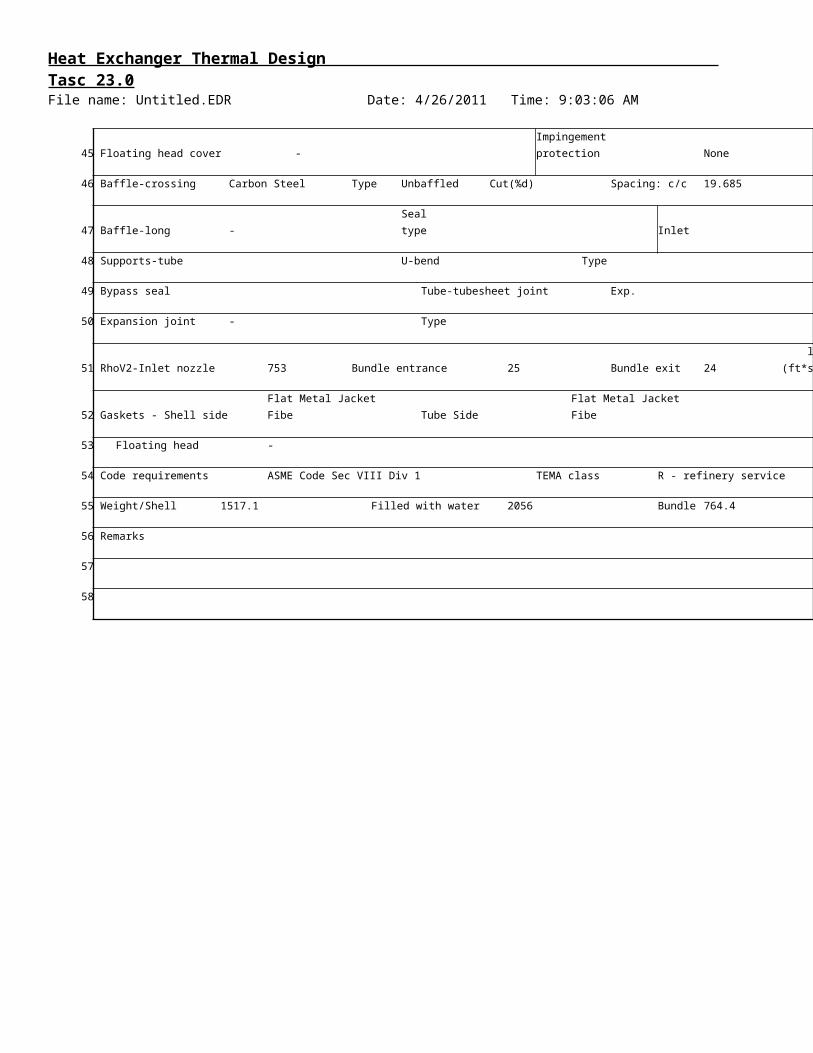
45 Floating head cover - Impingement protection None
46 Baffle-crossing Carbon Steel Type Unbaffled Cut(%d) Spacing: c/c 19.685
47 Baffle-long - Seal type Inlet
48 Supports-tube U-bend Type
49 Bypass seal Tube-tubesheet joint Exp.
50 Expansion joint - Type
51 RhoV2-Inlet nozzle 753 Bundle entrance 25 Bundle exit 24 lb/(ft*s2)
52 Gaskets - Shell side Flat Metal Jacket Fibe Tube Side Flat Metal Jacket Fibe
53 Floating head -
54 Code requirements ASME Code Sec VIII Div 1 TEMA class R - refinery service
55 Weight/Shell 1517.1 Filled with water 2056 Bundle 764.4
T1
T2 S1S2
Heat Exchanger Thermal Design Tasc 23.0File name: Untitled.EDR Date: 4/26/2011 Time: 9:03:06 AM
56 Remarks
57
58

Heat Exchanger Thermal Design Tasc 23.0File name: Untitled.EDR Date: 4/26/2011 Time: 9:03:06 AM
Overall Performance
Rating / Checking Shell Side
Total mass flow rate lb/h 16509
Vapor mass flow rate (In/Out) lb/h 0 0 0
Liquid mass flow rate lb/h 16509 16509 22046
Vapor mass quallity 0 0 0
Temperatures F 302 248 86
Dew point / Bubble point F
Operating Pressures psi 64.005 63.741 71.117
Film coefficient BTU/(h*ft2*F) 11.41
Fouling resistance ft2*h*F/BTU 0
Velocity (highest) ft/s 0.08
Pressure drop (allow./calc.) psi 3.75 / 0.264 7.25
Total heat exchanged BTU/h 476391 Unit BEM 2 pass
Overall clean coeff. (plain/finned) BTU/(h*ft2*F) 9.97 / Shell size 19
Overall dirty coeff. (plain/finned) BTU/(h*ft2*F) 9.97 / Tubes Plain
Effective area (plain/finned) ft2 198.1 / No. 334 OD 0.75
Effective MTD F 176.75 Pattern 30
Actual/Required area ratio (dirty/clean) 0.73 / 0.73 Baffles Unbaffled
Vibration problem (Tasc/TEMA) /
RhoV2 problem No Total cost 14726
Resistance Distribution
Overall Coefficient / Resistance Summary Clean Dirty
Area required ft2 270.5 270.5
Area ratio: actual/required 0.73 0.73

Heat Exchanger Thermal Design Tasc 23.0File name: Untitled.EDR Date: 4/26/2011 Time: 9:03:06 AM
Overall coefficient BTU/(h*ft2*F) 9.97 9.97
Overall resistance ft2*h*F/BTU 0.1003 0.1003
Shell side fouling ft2*h*F/BTU 0.0 0
Tube side fouling 0.0 0
Resistance Distribution BTU/(h*ft2*F) ft2*h*F/BTU % %
Shell side film 5028.21 0.0876 87.31 87.31
Shell side fouling 0 0
Tube wall 5028.21 0.0002 0.2 0.2
Tube side fouling * 0 0
Tube side film * 79.77 0.0125 12.49 12.49
* Based on outside surface - Area ratio: Ao/Ai = 1.21
Heat Transfer Coefficients
Film coefficients BTU/(h*ft2*F) Shell Side
Bare area (OD) / Finned area
Overall film coefficients 11.41 / 79.77
Vapor sensible 0 /
Two phase 0 /
Liquid sensible 11.41 / 79.77
Heat Transfer Parameters In Out In
Prandtl numbers Vapor
Liquid 8.63 10.33
Reynolds numbers Vapor Nominal
Liquid Nominal 843.28 654.57 1681.44
MTD and Flux
Temperature Difference F Heat Flux (based on tube O.D)
Overall effective MTD 176.75 Overall actual flux

Heat Exchanger Thermal Design Tasc 23.0File name: Untitled.EDR Date: 4/26/2011 Time: 9:03:06 AM
One pass counterflow MTD 177.86 Critical flux
LMTD based on end points 177.71 Highest actual flux
Effective MTD correction factor 0.99 Highest actual/critical flux
Wall Temperatures F
Shell mean metal temperature 273.96
Tube mean metal temperature 119.24
Tube wall temperatures (highest/lowest) 125.59 / 107.65
Duty Distribution
Heat Load Summary Shell Side
BTU/h % total
Vapor only 0 0
2-Phase vapor 0 0
Latent heat 0 0
2-Phase liquid 0 0
Liquid only 476391 100
Total 476391 100
Pressure Drop
Pressure Drop psi Shell Side
Maximum allowed 3.75
Total calculated 0.264
Gravitational 0
Frictional 0.264
Momentum change 0
Pressure drop distribution ft/s psi %dp ft/s
Inlet nozzle 3.83 0.096 36.46 4.22

Heat Exchanger Thermal Design Tasc 23.0File name: Untitled.EDR Date: 4/26/2011 Time: 9:03:06 AM
Entering bundle 0.7 0.28
Inside tubes 0.28 0.28
Inlet space Xflow 0 0
Baffle Xflow 0 0
Baffle windows 0.08 0.08 0 0.13
Outlet space Xflow 0 0
Exiting bundle 0.68 0.28
Outlet nozzle 6.13 0.167 63.41 6.98
Intermediate nozzles
Thermosiphon Piping
Piping reference points ft Pressure points psi F
Height of liquid in column Liquid level in column
Height of heat transfer region inlet Inlet to heated section
Height of heat transfer region outlet Boiling boundary position
Height of column return line Outlet of heated section 107.6
Exit of outlet piping
Pressure changes (-loss/+gain) psi Inlet circuit Exchanger
Frictional
Gravitational
Momentum
Flashing
Nozzles
Total
Inlet Circuit Piping
Inlet circuit element
Frictional pressure drop at entry psi
Frictional pressure drop at element psi

Heat Exchanger Thermal Design Tasc 23.0File name: Untitled.EDR Date: 4/26/2011 Time: 9:03:06 AM
Outlet Circuit Piping
Outlet circuit element
Frictional pressure drop at entry psi
Frictional pressure drop at element psi
Void fraction
Two phase flow pattern
Flow Analysis
Shell Side Flow Fractions Inlet Middle Outlet
Crossflow 0 0 0
Window 0.93 0.93 0.93
Baffle hole - tube OD 0 0 0
Baffle OD - shell ID 0 0 0
Shell ID - bundle OTL 0.07 0.07 0.07
Pass lanes 0 0 0
Rho*V2 Analysis Flow area Velocity Density
in2 ft/s lb/ft3
Shell inlet nozzle 3.356 3.83 51.406
Shell entrance 7.85 1.64 51.406
Bundle entrance 18.431 0.7 51.406
Bundle exit 18.431 0.68 52.9
Shell exit 6.053 2.06 52.9
Shell outlet nozzle 2.036 6.13 52.9
in2 ft/s lb/ft3
Tube inlet nozzle 3.356 4.22 62.262
Tube inlet 50.418 0.28 62.262
Tube outlet 50.418 0.28 62.043
Tube outlet nozzle 2.036 6.98 62.043

Heat Exchanger Thermal Design Tasc 23.0File name: Untitled.EDR Date: 4/26/2011 Time: 9:03:06 AM
Thermosiphons and Kettles
Thermosiphons
Thermosiphon stability
Vertical tube side thermosiphons
Flow reversal criterion - top of the tubes (should be >0.5)
Flooding criterion - top of the tubes (should be >1.0)
Fraction of the tube length flooded
Kutateladze Number in axial nozzle
Kettles
Recirculation ratio
Quality at top of bundle
Entrainment fraction
Methods Summary
Hot side
Heat Transfer Coefficient multiplier No
Heat Transfer Coefficient specified No
Pressure drop multiplier No
Pressure drop calculation option friction+acceleration
Calculation method Standard method
Desuperheating heat transfer method Wet wall
Multicomponent condensing heat transfer method HTFS - Silver-Bell
Vapor shear enhanced condensation Yes
Liquid subcooling heat transfer (vertical shell) Not Used

Heat Exchanger Thermal Design Tasc 23.0File name: Untitled.EDR Date: 4/26/2011 Time: 9:03:06 AM
Subcooled boiling accounted for in Set default
Post dryout heat transfer accounted for in No
Correction to user-supplied boiling curve Boiling curve not used
Falling film evaporation method HTFS recommended method
Single phase tube side heat transfer method HTFS recommended method
Lowfin Calculation method HTFS / ESDU

Heat Exchanger Thermal Design Tasc 23.0File name: Untitled.EDR Date: 4/26/2011 Time: 9:03:06 AM

Heat Exchanger Thermal Design Tasc 23.0File name: Untitled.EDR Date: 4/26/2011 Time: 9:03:06 AM
Basic Geometry
Unit Configuration
Exchanger type Tube number
Position BEM Tube length actual ft
Arrangement 1 parallel 1 series Tube passes
Baffle type Unbaffled Tube type
Baffle number 0 Tube O.D. in
Spacing (cen-cen) in 19.685 Tube pitch in
Spacing at inlet in Tube pattern
Shell Kettle Front head Rear Head
Outside diameter in 20.435 20.435 20.435
Inside diameter in 19.685 19.685 19.685
Shell Side Shell Side Shell Side Tube Side Tube Side
Nozzle type Inlet Outlet Inlet Outlet
Number of nozzles 1 1 1 1
Actual outside diameter in 2.375 1.9 2.375 1.9
Inside diameter in 2.067 1.61 2.067 1.61
Height under nozzle in 0.7577 0.7577
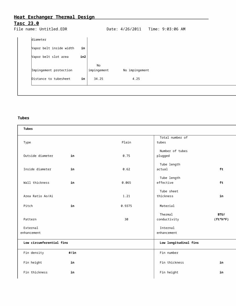
Dome inside diameter in
Vapor belt inside diameter in
Vapor belt inside width in
Vapor belt slot area in2
Impingement protection No impingement No impingement
Distance to tubesheet in 34.25 4.25

Heat Exchanger Thermal Design Tasc 23.0File name: Untitled.EDR Date: 4/26/2011 Time: 9:03:06 AM
Tubes
Tubes
Type Plain Total number of tubes
Outside diameter in 0.75 Number of tubes plugged
Inside diameter in 0.62 Tube length actual ft
Wall thickness in 0.065 Tube length effective ft
Area Ratio Ao/Ai 1.21 Tube sheet thickness in
Pitch in 0.9375 Material
Pattern 30 Thermal conductivity BTU/(ft*h*F)
External enhancement Internal enhancement
Low circumferential fins Low longitudinal fins
Fin density #/in Fin number
Fin height in Fin thickness in
Fin thickness in Fin height in
Tube root diameter in Fin spacing in
Tube wall thickness under
fin in Cut and twist length in
Baffles
Baffles
Type Unbaffled Baffle cut: inner/outer/interm
Tubes in window Yes Actual (% diameter) /
Number 0 Nominal (% diameter) /
Spacing (center-center) in 19.685 Actual (% area) /
Spacing at inlet in Cut orientation

Heat Exchanger Thermal Design Tasc 23.0File name: Untitled.EDR Date: 4/26/2011 Time: 9:03:06 AM
Spacing at outlet in Thickness in
Spacing at center in/out for G,H,I,J in Tube rows in baffle overlap
Spacing at center for H shell in Tube rows in baffle window
End length of the front head in Baffle hole - tube od diam clearance in
End length of the rear head in Shell id - tube od diam clearance in
Variable Baffle Spacings
Baffle spacing in
Baffle cut percent, outer
Baffle cut percent, inner
Number of baffle spaces
Baffle region length in
Baffle cut area percent, outer
Baffle cut area percent, inner
Supports - Misc. Baffles
Supports - tubes Longitudinal baffle
Supports under inlet nozzle Thickness in
Supports under outlet nozzle Window length at front end in
Supports between baffles 0 Window length at center in
Supports blanking baffles No Window length at rear end in
Supports at u-bend 0
Supports at in/out of G,H,I,J shell 0
Supports at center of H shell 0
Supports for K,X shells 0
Heat Exchanger Thermal Design Tasc 23.0File name: Untitled.EDR Date: 4/26/2011 Time: 9:03:06 AM
Bundle
Shell ID to center 1st tube row Tube passes
From top in 0.7577 Tube pass layout Ribbon (single band)
From bottom in 0.5643 Tube pass orientation Horizontal
From right in 0.5613 U-bend orientation undefined
From left in 0.5613 Horizontal pass lane width in
Vertical pass lane width in
Impingement protection None Interpass tube alignment
Impingement distance in Deviation in tubes/pass
Impingement plate diameter in Outer tube limit in
Impingement plate width in Shell id - bundle otl diam clearance in
Impingement plate length in Tie rod number
Gross surface area per shell ft2 215.2 Tie rod diameter in
Effective surface area per shell ft2 198.1 Sealing strips (pairs)
Bare tube area per shell ft2 198.1 Tube to Tubesheet joint
Finned area per shell ft2 0 Tube projection from front tsht in
U-bend area per shell ft2 0 Tube projection from rear tsht in
Enhancements
Internal enhancements
Tube insert type NoneTwisted tape
thickness in
Twist tape 360 deg twist pitch in

Heat Exchanger Thermal Design Tasc 23.0File name: Untitled.EDR Date: 4/26/2011 Time: 9:03:06 AM
Thermosiphon Piping
Inlet circuit
Inlet circuit element
Inside diameter in
Length or radius in
Number in parallel
Number in series
Outlet circuit
Inlet circuit element
Inside diameter in
Length or radius in
Number in parallel
Number in series
Cost/Weights
Weights lb Cost data
Shell 415.9 Labor cost
Front head 150.2 Tube material cost
Rear head 186.6 Material cost (except tubes)
Shell cover
Bundle 764.4
Total weight - empty 1517.1 Total cost (1 shell)
Total weight - filled with water 2056 Total cost (all shells)

Heat Exchanger Thermal Design Tasc 23.0File name: Untitled.EDR Date: 4/26/2011 Time: 9:03:06 AM

Heat Exchanger Thermal Design Tasc 23.0File name: Untitled.EDR Date: 4/26/2011 Time: 9:03:06 AM

Heat Exchanger Thermal Design Tasc 23.0File name: Untitled.EDR Date: 4/26/2011 Time: 9:03:06 AM
Tube Layout

Heat Exchanger Thermal Design Tasc 23.0File name: Untitled.EDR Date: 4/26/2011 Time: 9:03:06 AM