universityofcalifornia,santacruz ee129 …pnaud/reports/153-report-b.pdf · 6" "...
TRANSCRIPT

1
University of California, Santa Cruz
EE 129 Senior Design Project
Amateur Radio Satellite Ground Station
March 19, 2013

2
Team Introductions Jason Ragland, AG6RM, EE Project Manager Antenna design Andrew Martino, KJ6RFK, EE Documentation Motor control Sander Middour, KK6BSI, CE Procurement Microcontroller design Shashwat Kandadai, KK6BSH, CS Web Master Software design Mentors/Advisors Paul Naud John Vesecky Stephen Petersen Funding

3
Table of Contents Team Introductions ..................................................................................................................................... 2
Mentors/Advisors ........................................................................................................................................ 2
Funding ........................................................................................................................................................ 2
Purpose ........................................................................................................................................................ 4
Summary of Subsystems .............................................................................................................................. 5
Motors ..................................................................................................................................................... 5
Microcontroller ...................................................................................................................................... 13
Communications .................................................................................................................................... 25
Software ................................................................................................................................................ 33
Integration and Testing ............................................................................................................................. 39
Conclusion ................................................................................................................................................. 41
Appendix .................................................................................................................................................... 42
4
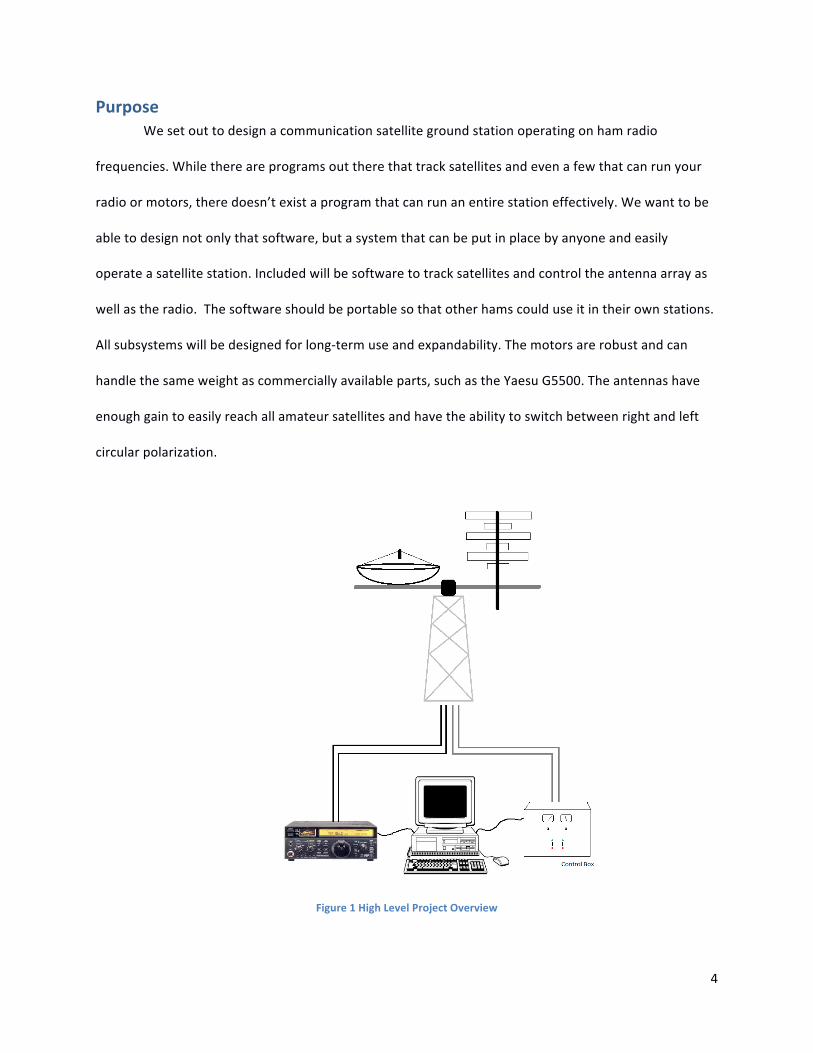
Purpose We set out to design a communication satellite ground station operating on ham radio
frequencies. While there are programs out there that track satellites and even a few that can run your
radio or motors, there doesn’t exist a program that can run an entire station effectively. We want to be
able to design not only that software, but a system that can be put in place by anyone and easily
operate a satellite station. Included will be software to track satellites and control the antenna array as
well as the radio. The software should be portable so that other hams could use it in their own stations.
All subsystems will be designed for long-‐term use and expandability. The motors are robust and can
handle the same weight as commercially available parts, such as the Yaesu G5500. The antennas have
enough gain to easily reach all amateur satellites and have the ability to switch between right and left
circular polarization.
Figure 1 High Level Project Overview

5
Summary of Subsystems Motors
The research that was conducted to aid in the preliminary design of the motor control and
manual Azimuth Elevation control systems was done by examining what current ARS operating ground
stations are using today and what things worked for them and what didn’t. I obtained most of this
information from the ARRL Satellite Handbook which is a comprehensive overview of station setup and
operating procedures that are necessary for communications with amateur radio satellites.
First the research for what the manual control box should contain began with a close
examination of the commercially available systems and what where their basic features and how could
these systems be improved on. This yielded a narrow result due to the fact that my research could only
turn up one fully assembled widely used commercial system, specifically the Yaesu G5500.(see motor
figure 2)
Figure 2 Yaesu G5500 commercial tracking system
After examination of the unit’s technical specifications, specifically the underlying driving circuitry that
translated digital and manual commands to motor motions, a good base line was established for the
functionality that our system should be able to provide. However to determine what things could be

6
improved upon from the G5500 our group consulted Professor Petersen, a veteran operator of Amateur
Radio satellites and an owner of a Yaesu G5500 and asked him some things he would change with the
G5500. The main thing that he thought could be improved was to have a continuous slew and not a
pulse mode to track satellites. After reviewing the technical documentation of the G5500 it was
discovered that it utilized relays to control motor movement. While simple to implement this design
does not lend itself to smooth slewing using slow periodic pulses to rotate the antennas resulting in a
jerking like motion at slow slew rates. The team was able to witness this at the ground station of
Professor Petersen first hand as he demonstrated the operation of the G5500 tracking a satellite pass.
This problem was decided to be solved in our teams system by not using relays but an H-‐Bridge
that would be able to use PWM to vary the speed of the motors, this way during slow speed tracking the
antennas and structure would not need to be put under unnecessary physical strain (jerking) to track a
satellite. This is due to the fact that PWM lends itself to a continuous slew rate as opposed to the slew
rate of discontinuous relay action that result in low frequency pulses. Using PWM also has the added
benefit of a more precise tracking system that it is able to follow a satellites path more closely and
thereby direct as much of the radio signal as possible towards the satellite resulting more efficient use
of transmitter power.
The other surprising realization that was made by observing the operation of professor
Petersen’s station was that the accuracy of the tracking system needed to communicate with a satellite
was not very high, for example, an angular error in either elevation or azimuth could be as high as +or-‐
15degrees while continuing to maintain contact. These observations lead me to believe that a simple
feedback control system to direct the motor motion would suffice. After some consideration on to what
kind of feedback control system would meet our desired specifications I determined that a simple
potentiometer with a corresponding bias voltage would be sufficient to guide the feedback control
required to track satellites. The benefits of using a potentiometer as a feedback device consisted of

7
simplicity of implementation, reduced cost; it retains its position value despite loss of power, and also
can allow for relatively accurate readings of position.
Next our preliminary design began to be formed and was decided it would include a manual
motor control system that would include displays that would give the operator an Idea of where the
antenna was pointing without the need to be connected to a computer or see the antenna. These
displays would be controlled by the feedback potentiometers that would provide information about the
relative position of the antennas. It was also decided that the system should also incorporate a logic
system that would allow for computer control as well manual control of motor movement, this system
would give the manual operator precedence over the computer. This logic system would interface to the
H-‐Bridge indirectly through optical couplers a device that allows for total electrical isolation between 2
systems through the coupling of the 2 systems through light. This electrical isolation between the logic
system and the H-‐bridge is to preserve the logic systems from dangerous transients that could be
damaging.
During the second quarter there were multiple integration system that were also brought to our
attention that required a preliminary design. One of these systems was a system that would restrict the
motor motion so as to not allow for unwanted motion of the antenna system, for example winding of
the coaxial cable. This system consisted of multiple relays acting in a sense as circuit breakers to prevent
the motor from driving the system to unwanted positions.
Other integration systems included the mechanical systems that would allow for the motor
rotation to control the position of the antenna. This consisted of a system of bearings and drive couplers
that were machined to fit into our high torque motors. (See motor figure 3 and 4)

8
Figure 3 Motor drive coupler shown. Also potentiometer feedback.
Figure 4 Antenna super structure with motors mounted

9
Figure 5 Motor drive block diagram
Tests Conducted:
I began my testing of our preliminary designs by observing the rotation rate of a linear
potentiometer verses its change on a voltage divider. I conducted this test to explore the viability of the
potentiometer position sensing system for use with tracking satellites. I set the system up to consist of a
linear potentiometer that has a range of 100 ohms per rotation in series with a 100ohm fixed resistor.
By biasing this system with a fixed voltage and measuring the voltage drop across the potentiometer I
was able to relate a voltage to a position. To use this data to keep track of antenna position I modified a
pair of digital voltmeter displays, specifically the Velleman 9v PMLED meter to show 360 for a 3.6volt
reading. The test was simple and involved only reading voltage from the potentiometers relating it to an
antenna position and displaying it in a characteristic way.

10
Next I conducted a long term reliability test on the power supply that was designed to power
the motors that were donated to our team by professor Elkaim. The motors were specified to run at
24volts with .5amps it was decided that to extend the life of the motors they would be run slightly
below the maximum voltage since even at 21volts the motors rotated plenty fast (in fact too fast) for the
tracking of satellites. I then began to first the power supply transformer for no load heat problems. The
reasoning behind these tests was that I was unable to obtain proper specifications on this part since I
bought it second hand. This was accomplished by the use of a Fluke thermal probe and running the
transformer no load for 48hrs and checking temperature variations, additionally heat testing was done
on the power supply by running the motors for long periods of time and measuring the temperature rise
of the transformer in a similar way using a Fluke thermal probe. The testing showed that the
transformer did not rise above ambient temperature and it was not necessary to use active cooling on
the DC power supply or aided cooling in form of a heat sink.
Next with testing the development of logic control involved working out on paper the logical
combinations that would result in a logical interface between the micro and manual interface and would
allow for the manual controller to have precedence over the micro controller. The results of these tests
resulted in the design of the logical system shown in (figure 6) .The test was set up with a signal
generator to represent the micro controller PWM signal and on – off – on switches to represent the
manual input. All outputs were attached to a Techtronic’s Oscilloscope and were monitored to verify
correct logic behavior. It was determined that the logic interface would work with the microcontroller
and then was routed to a PCB with allegro.
Before moving on to solidifying my H-‐Bridge design I needed to explore the ways in which
electrical isolation could be made between the H-‐Bridge and the Logic interface. Testing of the various

11
optical couplers (optical devices that offer total electrical isolation) involved selecting some low cost
Figure 6 Final circuit diagram of h bridge driver
optical couplers and sending them a series of pulses from a signal generator and observing the output
on the Tecktronic’s Oscilloscope and looking for rise time and decay characteristics as well as trying
different ways to bias the Darlington array that made up the optical receiving side. From this test it was
determined that the 4N33 was to slow and had biasing issues so the part was to be changed to the
6N137 which has a rise time of 23ns and a CMOS logic out put this proved to be a superior part and was
selected to swapped with the 4N33.
Testing the H-‐Bridge involved working with a small scale mockup of the H-‐Bridge system that
was intended for use and then scaling it up to a larger full scale system. This later turned out to not be
feasible due to over looked design problems with the high current H-‐bridge that was selected (the L298).
These design problems then lead to the need to create a full scale prototype using the board router and
a full scale test then ensued which proved successful and full motor control could be established using
PWM. After this test a final revision was developed and implemented as shown in figure 6 with this final

12
revision I have been able to successfully drive the motor system with no further problems, coming from
the H-‐bridge directly or any of its surrounding components.
The 2 final technical challenges that faced the motor systems included the position limiting and
various mechanical systems. While the UC machine shop allowed for rapid solving of the mechanical
coupling. The position limiting was slightly more involved, since the L298 H-‐Bridge like most current
driving circuits drives current using a totem of 2 BJT’s. Using this information I was able to determine
that by using a 2 position relay system I could limit the motion of the motor by cutting off its motion in
that direction by grounding the current sink in that direction. This would force the motor to stop
rotation in that direction and would only allow motion in a reverse direction. Then to trigger this stop I
wired the triggering coil of the relay to a 12v source and used the motor chassis ground as the triggering
system. By setting up sensing conductors at the 2 restricted positions for each motor and putting a
position needle on the drive shaft grounded through the chassis which allows for simple position
restriction of motor rotation. During testing I was able to successfully limit both elevation rotation and
azimuth rotation without incident.
Technical Problems:
-‐power supply: During the preliminary design phase of the DC power supply it was decided that active
cooling should be used to cool the DC power supply. As it turned out this decision was premature since
a lack of knowledge of how hot the system would actually get lead to the need to modify the
preliminary design to only include natural cooling.
-‐Motor controller: The original prototype was constructed using a bread board and small heat sink, this
was a direct result of a pushed time table and getting the motor controller ready for check off. This
resulted in the catastrophic failure of 2 consecutive L298 H-‐Bridges. It was then decided that the check
off deadline would be extended to allow for time to properly route the motor controller and acquire an

13
adequate heat sink. After the L298 was properly heat slinked and set up on an adequately routed board
the motor controller worked successfully and the heat problem was also mitigated. This aided in the
determination of the cause of the failures of the previous 2 L298s which was a combination of bad
contact with power and ground and an inadequate heat sink.
Microcontroller To interface and control the antenna position using the computer console, a
microcontroller was used as the medium between the computer console and the antenna
motors. This microcontroller should be capable of reading a movement command from the
computer console, reading the current antenna position, moving the antenna, and sending
current antenna position to the computer console.
Figure 7 High-‐Level Block Diagram of Microcontroller Function
The antenna will be moved by two motors, one controlling the Elevation angle (EL) and
one controlling the Azimuth angle (AZ). The angles will be determined by monitoring the
voltage from a potentiometer pot attached to each axis of the antenna. This will translate
angles from 0-‐360 degrees to analog voltages from 0-‐Vmax.

14
Figure 8 Look angle visualization
There are two ways to control the speed of a DC motor: by varying supply voltage and
pulse width modulation (PWM). First system is not convenient in digital systems since it
requires analog circuit, but the second system is very convenient for digital systems because all
controls is made using digital signal.
Finally, the microcontroller requires some kind of peripheral communication capabilities
back and forth between the computer console and the microcontroller. Some common
communication protocols are SPI, I2C, RS232, etc. However, we wanted to have USB
connectivity since most new computers don’t have serial ports. This requires us to use a virtual
USB (V-‐USB) converter (a.k.a. USB bridge).
The block diagram of the microcontroller interface is shown below. Note: this diagram is
the same for both the Azimuth and Elevation control. Only one motor is shown for simplicity
and clarity.

15
Figure 9 Block Diagram of Microcontroller I/O Interfacing
Process:
This task was broken down into the following parts:
1. Choosing an appropriate processor
2. Designing an I/O microcontroller development
3. Write firmware for reading ADC values
4. Write firmware for motor controls
5. Write firmware for USART
1. Choosing the processor:
Power consumption was not an issue since the microcontroller would have a constant
power supply. Physical size was also not an issue but price and speedy available was a concern.
Our main areas of concern were:
• High ADC resolution • Compatible with V-USB • Sufficient number of analog to digital ports to support • Dedicated hardware to provide a PWM signals for at least 2 channels • Cheap and readily available • At least 4KB of memory

16
Being able to read each motor position requires an Analog-‐to-‐Digital-‐Converter (ADC).
And since these voltages are representing angles, our needs required that the processor have
ADC with at least 10-‐bits of resolution in order to maximize the number of “angular steps” that
the microcontroller can move the antenna. 10-‐bits of resolution allows us to represent angular
degrees as small as 0.5 degrees using the relation:
(1024 steps)/(360 degrees) = 2.8 steps/degree à 1 step = 0.35 degrees
Since this is much less than the focal diameter of the antenna (approx 30 degrees), we conclude
that a 10-‐bit resolution ADC should suffice.
For USB interface, we looked at the CP2103 V-‐USB controller chip. The CP2103 is an
integrated USB-‐to-‐UART Bridge Controller providing a simple solution for updating RS-‐232
designs to USB using a minimum of components and PCB space. The CP2103 includes a USB 2.0
full-‐speed function controller, USB transceiver, oscillator, and an asynchronous serial data bus
(UART).
Figure 10 Block diagram for CP2103 V-‐USB from CP2103 datasheet

17
However, the datasheet for the CP2103 states a minimum processor speed of 1Mhz.
This means that we need a microprocessor with at least 1Mhz built in clock or the ability to use
an external frequency oscillator.
There are several processors that fit our requirements, but we chose the ATMEGA8L
based on the multiple tutorial and help sites on the Internet and written text.
2. I/O microcontroller Board:
In its most basic form, the UART hardware consists of a transmit (TX) line and a receive
(RX) line. The software configures how fast data is sent (the baud rate) and the specifics of the
protocol.
Since the UART module is asynchronous, there is no external clock line like the
synchronous protocols SPI or I2C. Instead, both communicating devices must have their own
clock sources configured to the same frequency. As long as these clocks match one another,
data should be transferred smoothly. Common baud rates include 4800, 9600, 19200, 57600,
and 115200 Mbits/s. The datasheet for the CP2103 tells us that it’s best to select a lower baud
rate to reduce the chance of errors. While there is a formula to determine the frequency and
BAUD rate, we used table 9 in the CP2103 datasheet to come up with a BAUD rate of 57600 and
a frequency 3.686MHz.
The CP2103 V-‐USB features simplify the SPI (Serial Peripheral Interface) type of interface
a great deal. Additionally, two standard SPI connectors are provided by the Atmel ISP (In
System Programmer); a 6 pin and a 10 pin connector. In addition to the data lines (MOSI and

18
MISO) and the bus clock (SCK), target voltage VTG, GND and RESET (RST) are provided through
these connectors.
Figure 11 Microcontroller board layout
Control Overview:
Controlling the antenna is a non-‐trivial component of the project. Resolution of the A/D
(Analog to Digital) converter will be a great concern on this micro as the analog signal from the
scanner will be extremely volatile and will consist of intermittent noise.
U2
ATMEGA8L
ADC619
GN
D2
5
(PC4/SDA) ADC427
GN
D1
3
Vcc1
4
(PC3) ADC326
(PC0) ADC023
(PC0/SCL) ADC528
ADC722
(PD0) Rxd30
(PD1) TxD31
(INT0) PD232
(INT1) PD31
(XCK/T0) PD42
(PC1) ADC124
(PC2) ADC225
(XTA
L/TO
SC1)
PB6
7 8(X
TAL2
/TO
SC2)
PB7
(MOSI/OC2) PB315
(AIN1) PD711
(SCK) PB517
(AIN0) PD610
(MISO) PB416
(T1) PD59
(~Reset) PC629
(SS/OC1B) PB214
(OC1A) PB113
(ICP1) PB012
Aref20
GND21
Av cc18
Vcc2
6
ADC5
ADC4
ADC3
ADC2
ADC1
ADC0
ADC7
ADC6
ADC[0:7]
J61
2
3
4
5
6
7
8
9
10
U1
CP2103
REG IN7
V BUS8
D+ (USB D+)3
D- (USB D-)4
NC215
NC013
NC114
~Suspend11 NC10
GND2
Suspend12
Reset9
VDD
6
Vio
(sup
ply
V)5
~RI (D in)1
DCD28
DTR27
~RTS23
~CTS22
NC421
NC320
GPIO118
GPIO217
GPIO019
GPIO316
TxD25
RxD24
DSR26
SG29
PAD
30
Y1
3.686MHz
DN1SP0503BAHT
4
13 2
VBUS
D-
D+
GND
C1(gnd)
C2(gnd)
J3USB CONN
1
2
3
4
5
6
J4ISP 6P
2 4 6
1 3 5
+3.3V
+5V
J1
HEADER 3
1
2
3 J2ISP 10P
2 4 6 8 10
1 3 5 7 9
PB2
PB1
PB0
PD7
PD6
PD5
J5
I/O Ports
1
2
3
4
5
6R1
100
R2
100
R3
100
R4
100
R5
100
R6
100
R7
100
R8
100
R9
47K
+ C64.7uF
+
C84.7uF
+
C1
4.7uF
L1100nH
SW1RESET
1 4
2 3
C21nF
C330pF
C430pF
C50.1uF
C9
0.1uF
C7
0.1uF
VCC
+3.3V USB+5V USB
VCC
+5V USB
+5V USB
Title
Size Document Number Rev
Date: Sheet of
<Doc> 1.0
microcontroller board
A
1 1Wednesday, March 06, 2013

19
Figure 12 Control block diagram
Motor position feedback is done by comparing the current position of the motor,
represented by a potentiometer pot voltage Vpot controlled by the motor, to a reference
voltage Vref, which represents the desired motor position.
ADC Reading:
The10-‐bit ADC resolution translates analog voltages to values between 0 and 1023 steps. If the
reference voltage is 5 volts, this means that the smallest detectable change in voltage on the
input pin is 5V / 1023 = 0.0049 volts or 4.9 mV/step. Since there are 360 degrees in 1024 steps,
we can expect an error of about 0.17 degrees per step.
We decided to use an average of multiple ADC read samples to average out noise, which
we can do easily in software. The flow diagram below shows the process for getting the
average of 32 ADC readings for an ADC pin using the ADC_Complete flag:

20
Figure 13 ADC Averaging Flow Diagram
Driving the DC motors:
The motor speed is set by the average voltage generated by a PWM signal on the I/O
board connected to the motor M+ terminal while the motor direction is controlled by a digital
I/O pin connected to the motor M-‐ terminal.
This average voltage works by separating the PWM signal in to 'on' time an 'off' time
within a cycle. One cycle is divided into a maximum number of steps and the Duty cycle is the
number of steps the signal is 'on' out of the maximum number of steps within the cycle.
The ISR_overflow (Interrupt Service Routine for timer overflow) determines the cycle
frequency by regulating how fast the steps increase.

21
Setting the direction was just a matter of changing the direction signal on M-‐ terminal
and the complement the Duty cycle on the M+ terminal. And turning the motor off was done
by setting the output to the M+ terminal the same as the M-‐ terminal (see diagram below).
Figure 14 ADC Averaging Flow Diagram
Lastly, we needed to implement the UART functions. We decided to use circular buffers
for character transmission and receiving in order to utilize the full duplex capabilities of SPI
interfacing and to avoid polling for data transfer completion. There are four separate parts for
the UART: receiving a char, transmitting a char, getting a char, and putting a char.
The Receive handling is done by the ISR_RXC (Interrupt Service Routine for Receive
Complete flag) every time the Receive Complete flag (RXC) is set. When this flag is set, this
indicated that there is new data (a character) in the Uart Data Register (UDR). The ISR_RXC will
then load the Receive circular buffer (RX_buff) with the new data at the tail.

22
Figure 15 ISR handler for Receive Complete Interrupt Flag: adds Char to RX_buff
Getting a character from the RX_buff is handled by the get_char() function which
removes data from the head of the RX_buff and returns it (see figure below).
Figure 16 get_char() function: Removes Char from RX buffer
The Transmit ISR and put_char(char) functions work similarly:
Figure 17 put_char(Char) function: adds Char to TX buffer
Figure 18 ISR handler for Register Empty Interrupt flag: adds Char to TX buffer
After all of the separate control modules were completed, tested, and debugged, we
wrote the one final module to integrate everything together. Commands from the computer
console were in the form of a 7-‐indices long character array. Each index was defined as follows:

23
Index 0 = START bit, indication the start of an instruction.
Index 1 = STATUS à send current antenna position to console
= MOVE à move antenna in the direction indicated at the indicated speed
index 2 = direction (u=up, d=down, l=left, r=right)
indices 3-‐5 = PWM speed from 0-‐100
index 6 = STOP bit, indicating the end of this instruction
Current status from the microcontroller to the console was in the form of a 13 indices long
character array indicating:
Index 0 = START bit, indication the start of the response.
Index 1 = ACK à last received command was a valid command
= NACKà last received command was invalid
indices 2-‐6 = Azimuth angle position
indices 7-‐11 = Elevation angle position
index 12 = STOP bit, indicating the end of the response

24
Figure 19 Flow Diagram for Main Program structure
Technical Problems and Changes:
Initially, we planned to have the microcontroller receive a desired antenna position
from the computer console and the microcontroller would handle moving the antenna to that
position using the Proportional, Integral, Derivative (PID) method with rotary encoders, and
sent a DONE flag to the console when complete. Prof. Pederson advised us that this was not
the best way since it would require a lot of memory and/or have slow response for our
application. Further research seemed to back this up. Based on our discussion with Prof.
Pederson, we decided that the microcontroller should just move the motors and monitor the
antenna positions and let the computer console handle position control since it can do it faster
and more dynamically.

25
The default clock speed that comes shipped with most AVRs is 1 MHz because they have
internal clocks which keep time. We needed to set up an external clock source to support the
V-‐USB, which requires a faster clock than the internal one. This proved to be quite a headache
but it turned out that the problem was within the ATMEL compiler environment.
The last problem was with the circular buffers for the UART. We were having an
intermittent problem with random garbage or skipped characters in the buffer. We later found
out that ''...it is VERY IMPORTANT that global variables which may be changed by interrupt code
are tagged as volatile. Failure to do this leads to a disastrous intermittent bug where rxq.length
is occasionally not incremented when it should be!'' ''... or compiler optimizations may lead to
incorrect code.'' [Embedded C Programming and the AVR, 2nd Ed].
Communications Antennas
Because there is no antenna class at our university a lot of research had to go into how
antennas work in order to prove that the antenna we designed would actually function and that
it was the best choice for the project. The ARRL Antenna Handbook was the first source that
was used. It covers all antenna theory from basic physics all the way up to design
considerations for antennas across all ham bands from frequencies from 2 MHz to 3 GHz. This
gave us a deeper understanding of how an antenna works and a better understanding of what
antenna type we should pick. From this research three antennas were chosen: the Yagi, helix,
and cubical quad.

26
The Yagi and helix are typically used in amateur satellite communication because of
their wide spread use and that there are many proven designs floating around. One thing about
ham radio is that if it works everyone will use it without really questioning it. We chose to be
different for a few reasons. We wanted to actually learn how an antenna works, we wanted a
unique station, and we wanted the antenna to meet certain needs. We went with the cubical
quad because of its adequate gain, wide beamwidth and compact size. The beamwidth is the
3dB area of coverage, while Yagis tend to have around 30° of beamwidth, the cubical quad that
we went with has a beamwidth of over 45°-‐50°. We wanted this because we wanted our station
to be able to not only communicate with satellites but be used for ground contacts in case of
emergencies or just for fun. A wide beamwidth helps ground communication so that you can
easily point your antennas at another station.
The antenna design comes from W4RNL (SK) L. B. Cebik. He was a prolific antenna
designer for the ham radio community. This particular design was nice because it has the 2m
and 70cm antennas on the same boom without much interaction between the two, since the
frequencies are third harmonics of each other. He ran many simulations on the spacing of the
elements as well as their lengths. He did not provide the antenna model, however, as he had
made a business on selling his models. The antenna had to be modeled to confirm his findings
so the NEC2 modeling software was used. The specific software package that was used was
“4nec2” which is a C++ implementation of NEC2. The dimensions from W4RNL were entered
into the software and the model checked out. There are algorithms to tweak the dimensions of
the antenna within the software to attempt to improve certain aspects of the antenna such as

27
gain, beamwidth, impedance, and SWR but the model was very solid and tried to maximize all
these areas already.
Figure 20 Cubical Quad antenna model
With a solid design already in hand, parts were selected and an actual implementation
had begun. A square aluminum tube, 2” in diameter, was used as the boom for its light weight
and rigidity. Square, wooden dowels make up the element spreaders which push the wire out
into a square. RG-‐62 coax feeds the antenna because it's impedance of around 93 ohms closely
matches that of the antenna's feedpoint impedance. Feeding the antenna at adjacent corners
with a phase difference of 90° causes circular polarization. The phase can be altered between
right and left with a pair of circuits that are placed on the antenna and at the control point.
CPOL Boards
If there is one drawback to satellite communication other than the fact that satellites
move, it’s circular polarization. When electromagnetic waves travel through the ionosphere
they tend to go from linear to circular polarization from what is called the Faraday Effect. This is
caused by the charged particles interacting with the EM wave in a way that causes rotating of

28
the electric field at a rate proportional to the frequency of the wave. Most satellites also
naturally spin in space and rotate about some axis, others are spinning on purpose. The
problem with a randomly rotating satellite is that the circular polarization sense will also
change from right to left and in between as the satellite tumbles. Most satellites are spun on
purpose to give them an inertia that points one side down. This is beneficial in a few ways. The
antennas can be put on that side and will also supply max power to the Earth. The satellite will
also have a “permanent” spin sense of left or right. Waves that are already circularly polarized
are less affected by the Faraday Effect which is also a benefit of this.
With the satellite supplying circular polarized waves, our ground station now has to be
able to receive such waves. We can set up our antenna to be circularly polarized, but if we
make it only able to go right or left circular, then we would have to have a pair of antennas for
each frequency band. This problem is accomplished by having a circuit that can switch the
polarization sense of the antenna with a switch. There was no commercially available circuits
that we could just buy to accomplish this task, so we decided to use a design that AC6P,
Stephen Petersen, came up with. His design utilizes RF switches, in the form of PIN diodes, to
add 180 degrees of phase to one side of the feed point of the antenna. These 180 degree shifts
will switch the polarization from right to left and vice versa.
The first board I worked on was the control board that would stay in the station and
reside in the control box. Figure 21 shows the schematic for the control board circuit. This
circuit implements a few flip flops that allow a switch to send a ‘1’ or ‘0’ to the boards on the
antenna. Two saturation amplifiers will “rail” the voltages to 0V or 5V and the antenna board

29
will do what it needs to do to bias the PIN diodes properly. This board also supplies a 12V rail
to the antenna board because the diodes become fully biased in either direction with 12V.
Figure 21 CPOL control board
The next board was the circular polarization, CPOL, board that would go onto the
antennas. Figure 22 shows the schematic for the circuit. It uses an impedance matching Pi
network at the input that matches 50 ohms from the coaxial feed line to 93 ohms on the

30
antenna/boards.
Figure 22 CPOL antenna board
The cross hatches lines on the schematic represent transmission lines that are set at 93 ohms.
Diodes D1, D2, and D3 are PIN diodes which are used as RF switches. When forward biased they
pass RF and look like a 1 ohm resister. When reverse biased they look like a capacitance and
block RF. When D2 is on, D1 and D3 are off. When D2 is off, D1 and D3 are on. With D2 on the
signal from the input will travel down the first Tx line and go directly out of the two sma
connectors on the right side of the board. When D2 is off the signal has to go through the Tx
line on the top, left. The dashed line represents a length of coax cable that, along with the Tx
lines on the left, makes a half wavelength shift in the wave that travels on it. This means that

31
when D2 is on, the two waves that exit on the right of the board will be in phase and when D2 is
off, the two waves that exit will be 180 degrees out of phase.
The biasing is accomplished by feeding our logic signals to a half h bridge. 5V
corresponds to a positive 12V bias and a 0V logic level corresponds to a -‐12V bias across the PIN
diode. This circuit will go into a control box with the microcontroller and motor logic. The I/O
will be a switch for the 70cm and 2m antennas and LEDs for left and right for each. The logic
outputs and 12V signals will be sent to the antenna via a DB-‐9 connector and 4-‐pair shielded
cable.
ICOM CI-‐V
In order to control and read data from the radio we needed to match its serial interface
on the back of the radio. Most ICOM radios use a 3.5mm jack with an open collector driver to
communicate with one another. The catch is that they don’t plug right into each other, but use
a proprietary circuit that ICOM calls their “Communication Interface” or IC. They put this circuit
in a box with a DB-‐9 to connect to your computer’s serial port, because every computer has a
serial port still. And then it has a few 3.5mm jacks. The idea is that you can daisy chain up radios
with the mono audio cables and be able to control all your radios. The black box that houses
the circuitry costs in the neighborhood of $135 (http://www.hamradio.com/detail.cfm?pid=H0-‐
003750, 6-‐12-‐13) and a DB-‐9 to 3.5mm cable can be purchases from various sources or made by one’s
self.
While this is all and good, there is no reason to pay that much money for something so
simple. A simple Google search on “homemade icom ci-‐v” gives countless examples of people
attempts, failures, and successes in making their own circuit. All the circuit has to accomplish is

32
have an open collector driver/receiver and convert that to an RS-‐232 port. Because not all
people have a serial port on their computers anymore it would be advantageous to convert that
serial connection to something more useful, like USB. Discussed at length in the microcontroller
section is the CP2103 USB to UART bridge chip. We used the same chip for this part of the
project, only in this case we used a pre-‐made breakout board from Sparkfun because we had
one laying around.
Figure 23 ICOM CI-‐V
With a way to easily communicate with our computer we needed the open collector
buffering part of the circuit. Once again, AC6P came to the rescue with a simple circuit that
accomplishes this task. Figure 23 shows our “ICOM CI-‐V” interface board. It consists of a 6 pin
header to connect to the USB to UART bridge board and two open collector buffer chips, one
for transmit and one for receiver. There is also some biasing components and RF choking. The

33
I/O for the radio is a 3.5mm mono jack. We added an extra jack in the case where we wanted to
hook up an HF radio in the future.
Problem Areas
The main issue with the antennas, as stated above, is that neither of us had any real
idea how any antenna other than a dipole worked. We had to build up our knowledge of
antennas over a few weeks before we could get to satellite antennas and circular polarization.
We had to do a link budget to make sure that the antenna would have enough gain as well. The
modeling software was also a troublesome area as the first one that we used, NECWin Pro, has
a very clunky interface and not much help can be found on the internet. Learning the NEC2
software was also difficult as we didn’t have much time to get a model ready and it has a fairly
steep learning curve. Once we started using 4nec2 is became much more manageable as the
help files were very useful and readable and there is a fairly large network of users of the
software.
Software We began by familiarizing ourselves with the major papers written on this subject. Most
famously, Space-‐Track Report #3 (http://celestrak.com/NORAD/documentation/spacetrk.pdf)
served as the basis of our understanding. This paper describes in detail the SGP4 algorithm,
used by NASA and NORAD to convert ephemeris to position and velocity of a satellite at any
given time. This paper, though a landmark work, is incredibly dense, so we ended up relying on
TS Kelso's CelesTrakcolumns (http://celestrak.com/columns/). Kelso makes clear how to
reference a satellite's position relative to a ground observer, which is non-‐trivial. Kelso makes
clear the importance of using geodetic coordinates over spherical. Kelso also goes into detail

34
about the importance of sidereal time. Kelso's papers were supplemented by
http://satelliteorbitdetermination.com/orbit_elements_wiki.htm and
http://www.physics.ncsu.edu/courses/astron/orbits.html#MA, which describe important
components of SGP4 and orbital propagation in general. With regards to rotating frames of
reference, we found the handouts for the ASEN5070 at University of Colorado Boulder
(http://ccar.colorado.edu/ASEN5070/handouts/coordsys.doc), to be very enlightening.
“Simplified perturbations models are a set of five mathematical models (SGP, SGP4,
SDP4, SGP8 and SDP8) used to calculate orbital state vectors of satellites and space
debris relative to the Earth-‐centered inertial coordinate system.”
(http://en.wikipedia.org/wiki/Simplified_perturbations_models, 6-‐12.-‐13). The SGP4 models takes
the two line elements, TLEs, from NORAD which are themselves coefficients of Kepler’s
equation and some identifying information. These numbers are then turned into useful
information that we can use such as the velocity of the satellite and its position relative to the
center of the Earth. We then convert this position to spherical coordinates because it is more
useful to us. With spherical coordinates we can then calculate look angles of elevation and
azimuth relative to our position on the Earth. This is tricky because the Earth itself is not a
sphere, it is squashed into an “oblate spheroid” shape. Kelso goes into great detail on how to
model the Earth to compensate for this and to make the satellite position much more accurate
than it would have if we ignored this fact.
For the implementation, we used Brandon Rhodes' Python SGP4 implementation
(https://pypi.python.org/pypi/sgp4/) as our base material. Rhodes' code is based off Vallado's C++
implementation (http://celestrak.com/software/vallado-‐sw.asp). We used Rhodes’ approach of

35
“Least Interference”, and only changed the lines of code which directly required a changed
(could not work in JavaScript). The JavaScript library is promising, and stands up to some
benchmarks such as the savage benchmark (http://celestrak.com/columns/v02n04/).
Testing
Figure 24 Chrome app as it stands right now
To verify our SGP4 implementation into JavaScript works we ran the supplemental
testing TLEs provided in Space-‐Track Report #3
http://celestrak.com/NORAD/documentation/spacetrk.pdf). This method of testing supplies the
SGP4 with specific inputs, for which the outputs are known. We can compare the outputs from
our own SGP4 algorithm with the known outputs. Running these TLEs gave us an error that was
really small, 1 in 1 million. This was promising and from this we knew we could trust our values.

36
With the SGP4 code tested and benchmarked we knew we could proceed with the software
and start implementation with other systems.
Software Architecture
The Main Thread (which includes Worker Manager) ONLY deals with initial setting up of the JS
environment, and responding to various callbacks. This ensures that its number one priority
remains Graphics Refresh, via the requestAnimationFrame() call. Otherwise, the Main Thread
will delay Graphics updates for other logic, the graphics will appear choppy, and the UI will
seem non-‐responsive. The Main Thread relays any UI commands that require a change in the
WebGL objects (such as zooming, rotating, tracking a satellite), to the WebGL Renderer, and
allows it to update the 3D world.

37
The Tracking worker is told which satellites to track, and regularly reports those satellites’ live
position. It runs one SGP4 calculation per satellite being tracked, every update cycle, and
returns all the live values for each satellite.
The Propagation worker is given a satellite and told to provide several position coordinates in
an array, depicting the satellite's path of travel. This thread does many SGP4 calculations for a
single satellite over a given span of time.
AngularJS Architecture
AngularJS provides us with “two-‐way data binding”, which means that the data in the
Presentation layer (HTML/CSS) will always be consistent with the data in the Model, regardless
of which one is changed. AngularJS divides a project into four sections, Controllers, Services,
Filters, and Directives. The Controllers and Services are the most important aspects of this
particular project.

38
Controllers
The Controllers should all be very small, and should be limited to setting up the Model,
instantiating the Services, defining callbacks for UI events, and not much else.
This app is a single view, currently run by UICtrl, which is quite simple. UICtrl takes in user
mouse/keyboard actions and relays them to Services like ThreeJS and WorkerManager.
Services
Services are singletons, often used to encapsulate Web APIs, but here they are used to wrap up
complex local logic.
ThreeJS is used to abstract the WebGL world from the AngularJS/HTML/CSS world. UICtrl
detects user actions, such as scrolling, and informs ThreeJS to appropriately update the 3D
objects.
WorkerManager corresponds exactly to the Worker Manager in the Software Architecture. This
Service instantiates Web Workers (threads), sets up their callbacks, and provides the Web
Workers with their parameters. Both UICtrl and ThreeJS rely on WorkerManager to provide up-‐
to-‐date satellite tracking information, for display in HTML and WebGL.
The Radio and Motor Services encapsulate the hardware control logic. It does not rely on Web
Workers, because the chrome.serial API is only available from the Main Thread. They both rely
on WorkerManager to provide them with up-‐to-‐date tracking information.
Technical Problems

39
The software was one of the biggest trouble areas for us mostly because it was central
to the entire project. Interfacing hardware to software is hard enough most of the time but we
had a lot of layers of abstraction to deal with by using a Chrome app. We had a few issues with
the microcontroller that we figured out after a few weeks of debugging. Motor control,
however, was the biggest problem area. Implementing logic to move an antenna array
intelligently is not a trivial problem in the slightest. Pointing the antenna at the satellite by
taking the shortest path seems easy, but if you don’t want to wrap the cables around the tower
you have to keep track of where you are and try to stick to one side of the tower. Also since we
wanted hard limiting of motion, we had to try not to cross those boundaries. At this time we
have yet to implement fully intelligent antenna control and are relying on a “dummy” approach
where we take the shortest path and just keep the antenna favoring one side so we don’t cross
over the hard limiters. In the future we plan to have a “flip mode” where we can flip the
antenna past 90 degree elevation in order to compensate for the hard limiting.
Integration and Testing Integration and testing is always one of the biggest problem areas for projects like this
and our project was no different. With all the main parts of our project completed by the first
week of Spring quarter, we set out to connect these parts and the subsystems of our project
began to take shape. The microcontroller was the translation between the computer and the
motors. The antenna system had a few circuits as well as interfacing with the radio. And the
software was a bunch of modules that now had to interact with each other in an event driven
scheme that was by that point not thought up yet. Integration and testing would not end until
the last possible day because of unforeseen issues.

40
One of the first systems to see integration was software control of the radio. Because
we used a proven design for the serial interface board there wasn’t much testing that had to
occur. The bulk of the problems with that system was getting Chrome to open up a serial port.
Plugging the board into the computer and radio and running AC6P’s program was a breeze and
there was no issues. But we had nothing but trouble in getting our software to work. The issue,
as it turned out, stemmed from Chrome’s clunky way of handling hardware. For security
reasons Chrome makes it very hard to interface with hardware and we had to look up many
tutorials on USB and serial ports to get it to work, but after a week or so we were able to
change the radio’s frequency.
The second major subsystem to be completed was the motor logic and power system.
All the components of this system were mocked up and tested in the first quarter, but up to
that point no boards had been populated and the system as a whole was disconnected. The
logic board was populated and the h bridge board was laid out and routed on the board router.
We had a lot of issues with the h bridge chips because of how they were designed and our lack
of understanding of them. We burned a few up in experimenting and finally came up with a
fairly bomb-‐proof design. We were able to manual move the motors early in Spring quarter and
were doing motor control through the microcontroller soon after that. Full system integration
with the Chrome app would not happen until the last week of the quarter due to some
software bugs and logical errors, but we were finally able to move the antenna and track
satellites on the bench.

41
Conclusion We have accomplished a lot this year but we still have a few features that we would like
to implement before we call this project complete. We eventually want to try to get our code
running on some commercially available microcontrollers like an Arduino or PIC32. The end goal
is to make our project an open source satellite tracking system. We believe we have a novel
way of getting the Yaesu G5500 working under pwm control and integrated into our system. If
we could work this out our system would be completely open source. Our software is available
on github, https://github.com/shashwatak/EarthStation, and soon our PCB layout and
microcontroller code will be available. Some of us plan to work on this during our free time
over the summer to make this a reality. I think the ham radio community would appreciate this.

42
Appendix
Figure 25 Hardware block diagram

43
Figure 26 CPOL antenna board

44
Figure 27 CPOL control board
Figure 28 ICOM CI-‐V
45
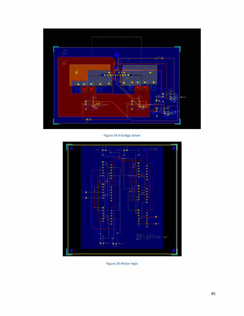
Figure 29 H bridge driver
Figure 30 Motor logic