university of washington - bridges.transportation.org · university of washington. aashto scobs...
TRANSCRIPT
Accelerated Bridge Construction –Developments on the Earthquake Frontier
John StantonUniversity of Washington
AASHTO SCOBS meetingSpokane WA, 12 June 2017
Outline
ABC in Seismic Regions• What are the challenges?• Family of design concepts.• Connections for emulative and other systems.• Systems for enhanced seismic performance.

Challenges
SPMT Lateral slide PBES
ABCHow?
Bents Superstructure
Where?
Challenges
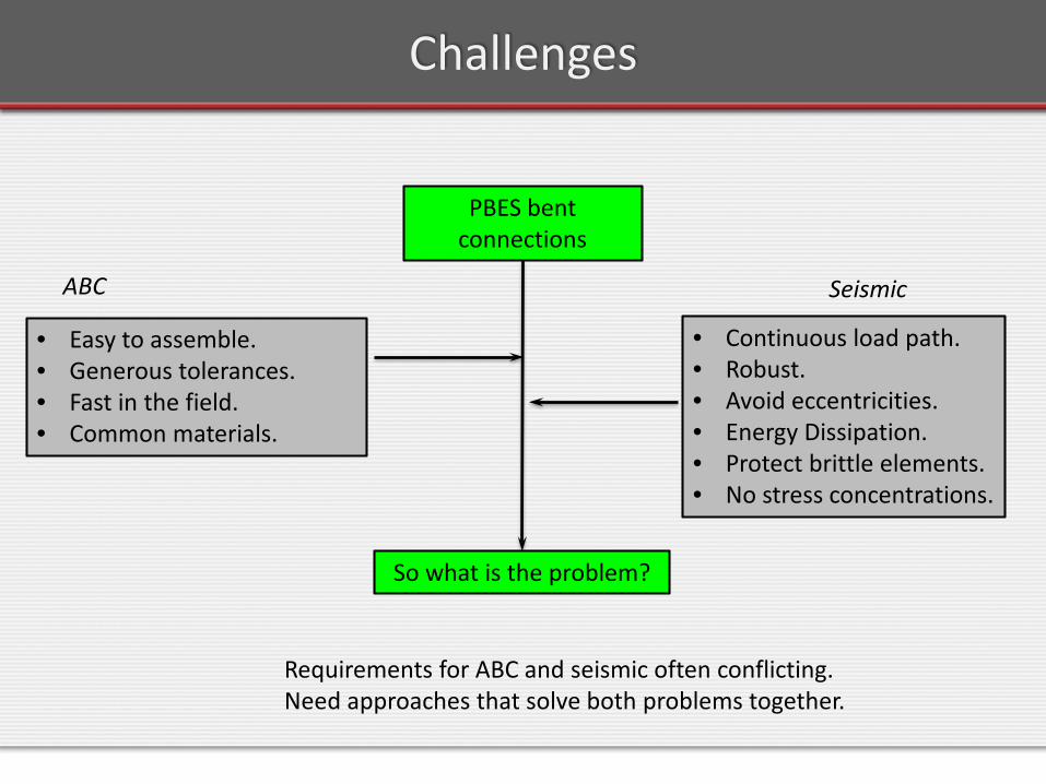
PBES bent connections
• Easy to assemble.• Generous tolerances.• Fast in the field.• Common materials.
ABC
So what is the problem?
• Continuous load path.• Robust.• Avoid eccentricities.• Energy Dissipation.• Protect brittle elements.• No stress concentrations.
Seismic
Requirements for ABC and seismic often conflicting. Need approaches that solve both problems together.

Challenges
• Can ABC be achieved with the same seismic resistance as for conventional construction?
• Can we improve seismic performance with ABC?
• Present approach: Life Safety.• Possible objectives (Immediate Operation): No residual drift.Low damage.

ABC & Enhanced Seismic Performance
The field is yet young.• Many ideas.• Some: ABC = good , seismic = same. • Others: ABC = marginal. Seismic = good.• A few: Both = good.• Combine concepts and details to suit
particular project.
Family of Connections
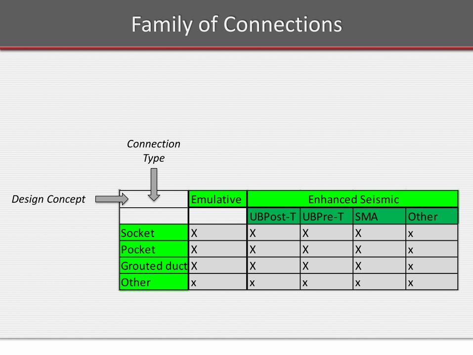
EmulativeUBPost-T UBPre-T SMA Other
Socket X X X X xPocket X X X X xGrouted duct X X X X xOther x x x x x
Enhanced SeismicDesign Concept
Connection Type
Precast emulative construction
Emulative Construction
• No new concepts to prove.
• Easier acceptance: “performs just like c.i.p.”
• But, use of precast shortens time on site.
Versatile Connection Types
Common connection concepts for emulative (and other) systems:
• Socket connections
• Pocket connections
• Grouted ducts and sleeves
• Other mechanical connections
Versatile Connections - Sockets
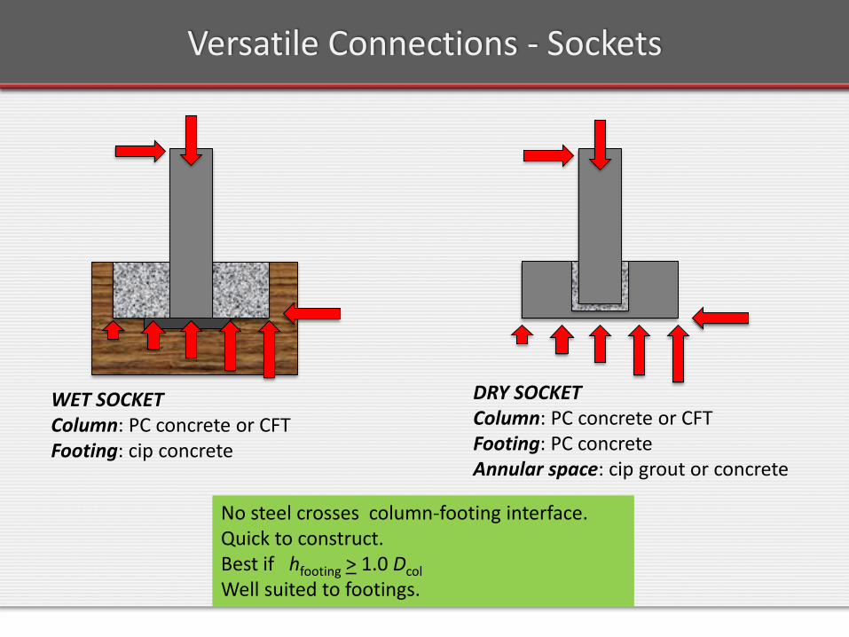
WET SOCKETColumn: PC concrete or CFTFooting: cip concrete
DRY SOCKETColumn: PC concrete or CFTFooting: PC concreteAnnular space: cip grout or concrete
No steel crosses column-footing interface.Quick to construct.Best if hfooting > 1.0 DcolWell suited to footings.
Sockets – Precast Concrete Column
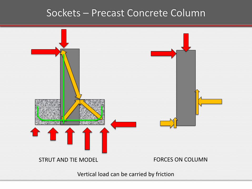
STRUT AND TIE MODEL FORCES ON COLUMN
Vertical load can be carried by friction
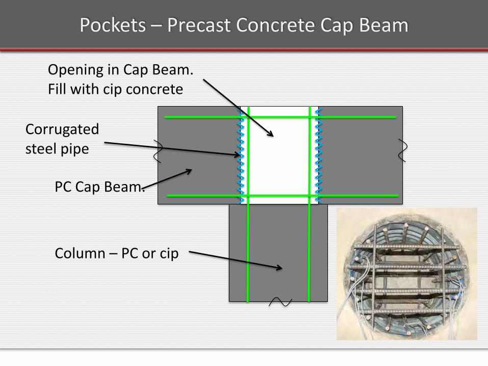
Pockets – Precast Concrete Cap Beam
Opening in Cap Beam. Fill with cip concrete
PC Cap Beam.
Column – PC or cip
Corrugated steel pipe

Pockets – Precast Concrete Cap Beam
Critical node - CCT
Force transfer from column tension steel:• Occurs at top node.• Helped by corrugated tube.
Connection good for cap beams, not footings.
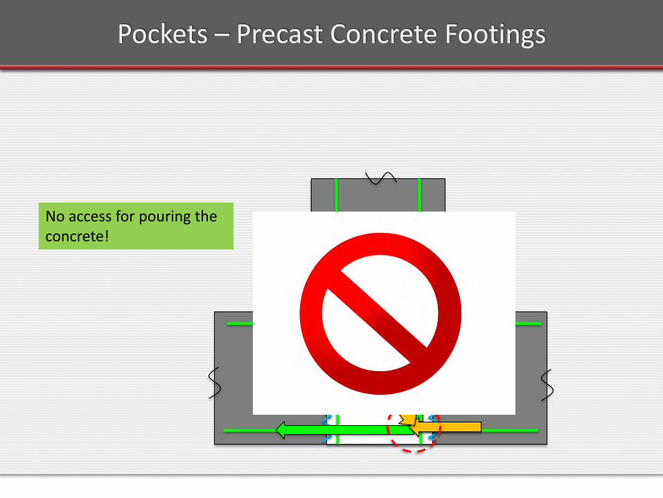
Pockets – Precast Concrete Footings
No access for pouring the concrete!
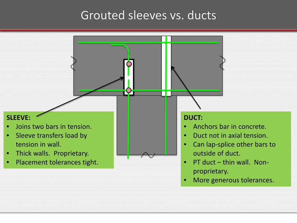
Grouted sleeves vs. ducts
SLEEVE:• Joins two bars in tension.• Sleeve transfers load by
tension in wall.• Thick walls. Proprietary.• Placement tolerances tight.
DUCT:• Anchors bar in concrete.• Duct not in axial tension.• Can lap-splice other bars to
outside of duct.• PT duct – thin wall. Non-
proprietary.• More generous tolerances.

Grouted sleeves and ducts
IN FOOTING• Bars project from column.
Potential difficulty in transportation.
• Debris in sleeves?• Harder to access grout
ports.
IN COLUMN• Stiff sleeve inhibits plastic
hinge formation.• Tie fit problem.
WHERE TO PLACE THEM?Consider both strength and deformation capacity.
Plastic zones

Grouted sleeves and ducts
WHERE TO PLACE THEM?Consider both strength and deformation capacity.
Bar stressGood confinement = good bond.Strain concentration.
• Cover spalls. • Bars more prone to
buckling.
• Low moment. • Bars may not
yield.
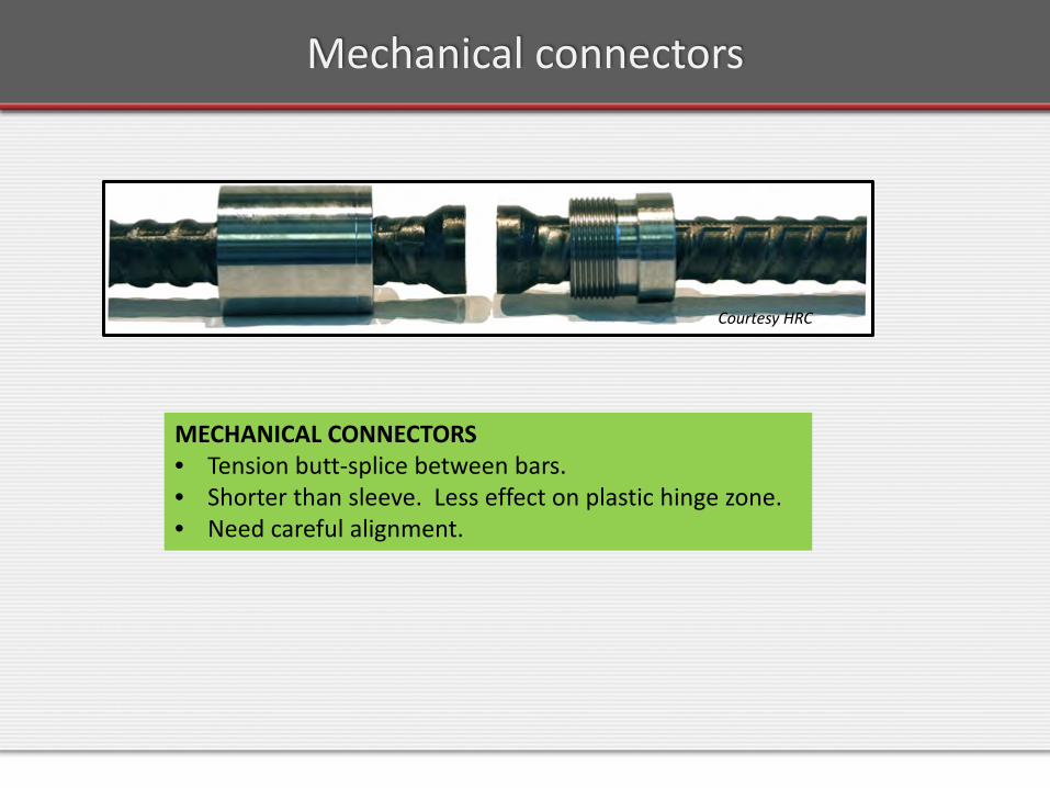
Mechanical connectors
MECHANICAL CONNECTORS• Tension butt-splice between bars.• Shorter than sleeve. Less effect on plastic hinge zone.• Need careful alignment.
Courtesy HRC
Emulative Systems
Emulative Systems Approach• Precast intended to achieve seismic response of c.i.p.• Connection designed to be as strong as the column, so • Inelastic action is forced into the column.
Thus the name: “EMULATION”

Emulative Systems: What to Precast
• Precasting the cap beam is the biggest time-saver. Saves time for:• Shoring• Formwork• Rebar placement and fixing • Casting-curing cycle
• Precasting the column saves time, but:• Many contractors prefer c.i.p. columns (keeps
work in-house).• Time savings are less than with cap beam.
Emulative Systems – Grouted Ducts
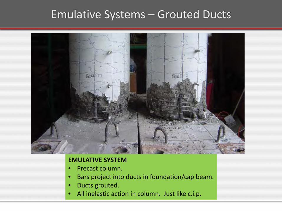
EMULATIVE SYSTEM• Precast column.• Bars project into ducts in foundation/cap beam.• Ducts grouted.• All inelastic action in column. Just like c.i.p.
Emulative Systems – Grouted Ducts
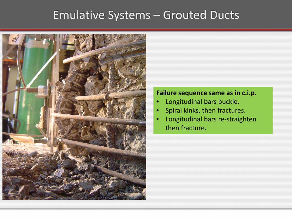
Failure sequence same as in c.i.p.• Longitudinal bars buckle.• Spiral kinks, then fractures.• Longitudinal bars re-straighten
then fracture.
Emulative Systems – Grouted Ducts
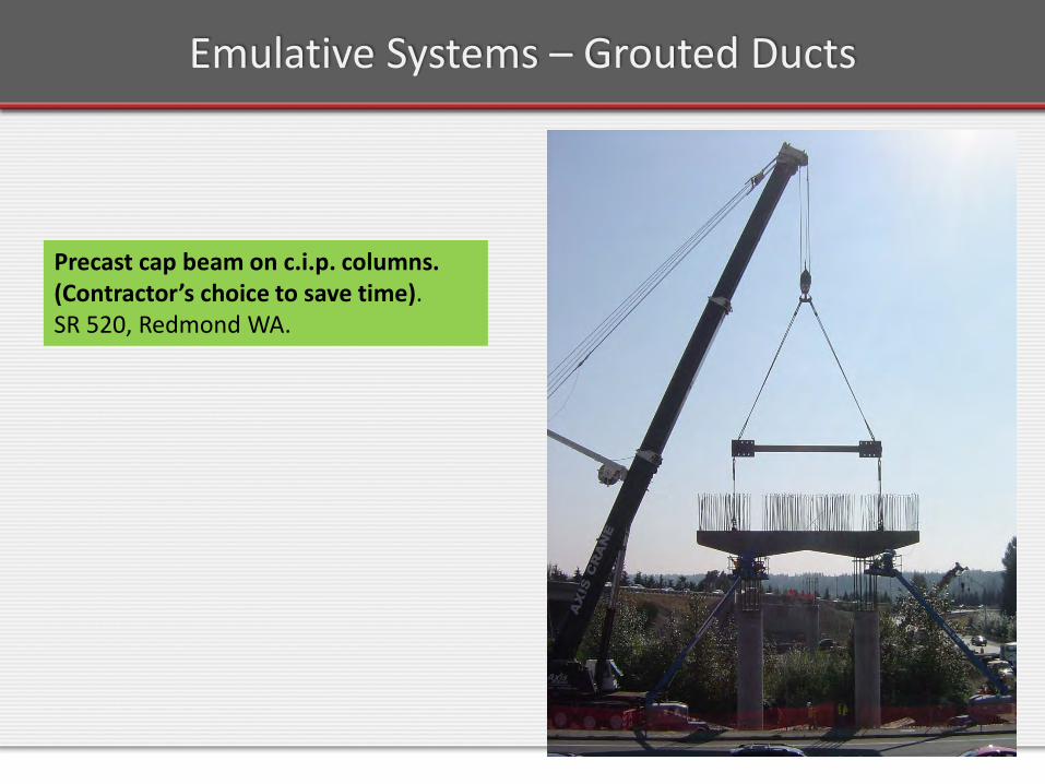
Precast cap beam on c.i.p. columns.(Contractor’s choice to save time).SR 520, Redmond WA.
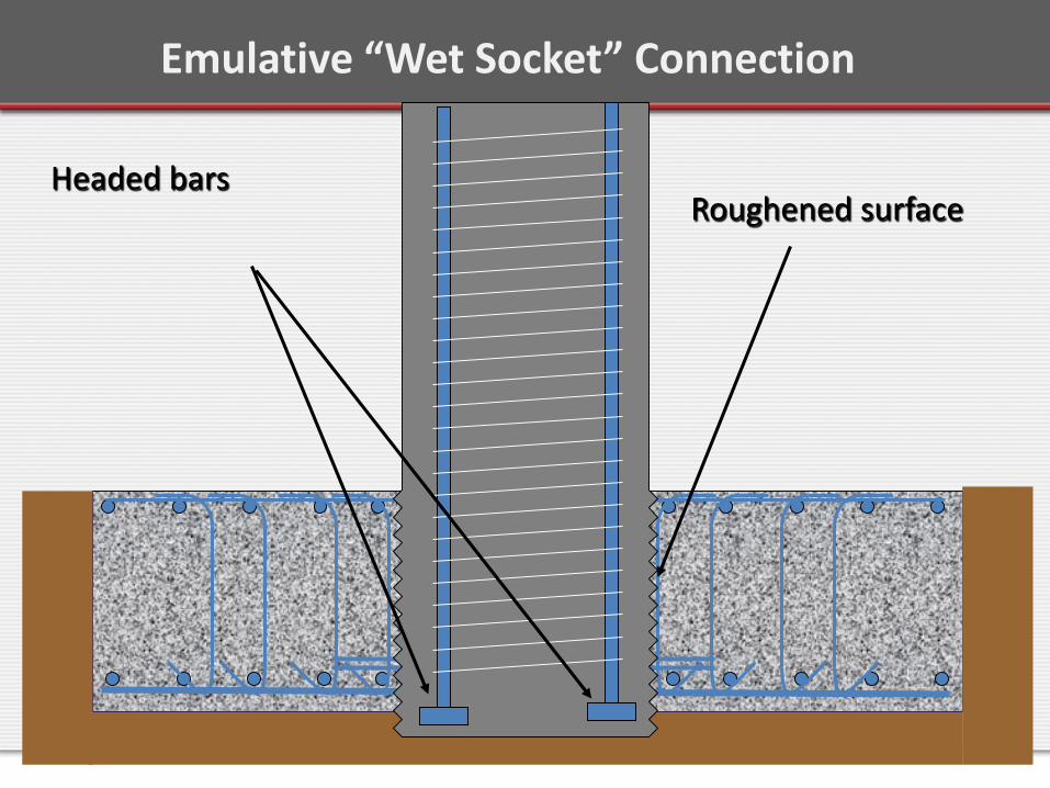
Emulative “Wet Socket” Connection
Headed barsRoughened surface

Emulative Wet Socket Connection

After seismic testing. All inelastic action in column. Foundation undamaged.
Emulative Wet Socket Connection
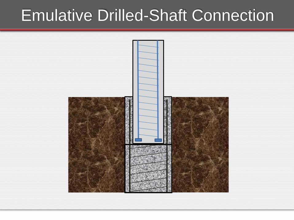
Emulative Drilled-Shaft Connection

Emulative Drilled-Shaft Connection
DS-1 DS-2
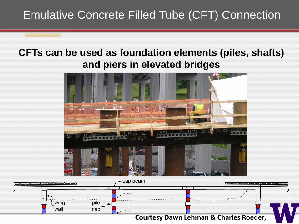
CFTs can be used as foundation elements (piles, shafts) and piers in elevated bridges
Emulative Concrete Filled Tube (CFT) Connection
Courtesy Dawn Lehman & Charles Roeder,

Welded Dowel (WD)Embedded Ring (ER)
Emulative Concrete Filled Tube (CFT) Connection

Emulative Systems
Connections in Emulative Systems – Summary
• All of the major connection types (Socket, Pocket, Grouted Sleeves or Ducts, Mechanical Connectors) have been tested under cyclic loading.
• All can provide sufficient strength.• Most can provide ductility equal to or better than
c.i.p. construction. • Ductility depends strongly on details.
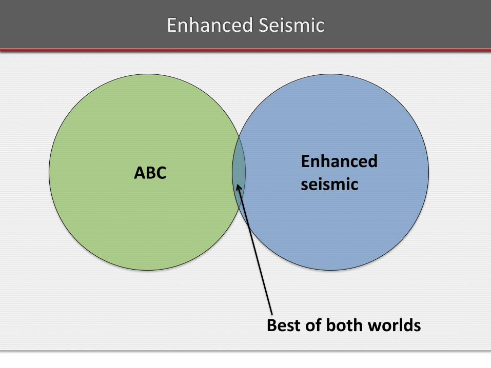
Enhanced Seismic
ABC Enhanced seismic
Best of both worlds
Enhanced Seismic
Conventional, bonded, cip construction:
“So you want to protect the columns by deliberately inflicting damage on them?”
Bars must yield to dissipate energy, butBar yielding causes large strains and damage.
Use of debonded reinforcement offers an alternative.
Enhanced Seismic
Most work has been done on• Re-centering – “Zero residual drift".• Minimizing damage to columns – no bridge closure.• Combinations of the two.
Re-centering can be achieved by • Unbonded Post-tensioning.• Shape memory alloy (SMA) reinforcement.
35
RE-CENTERING SYSTEMS
Unbonded Post-tensioned Bumble Bee
Re-centering system hysteresis Loops
100/0
25/75
50/5075/25
0/100
% elastic/% yielding
Nonlinear elastic
Nonlinear inelastic
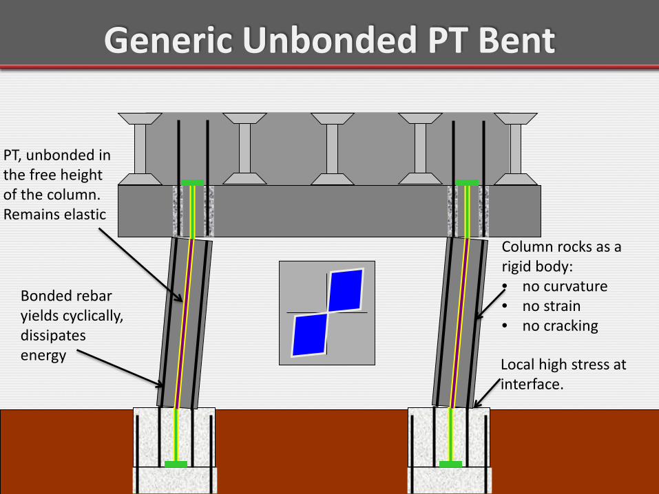
Generic Unbonded PT Bent
PT, unbonded in the free height of the column. Remains elastic
Local high stress at interface.
Column rocks as a rigid body: • no curvature • no strain • no cracking
Bonded rebar yields cyclically, dissipates energy
Re-centering Low Damage System→ Low Damage Detailing 38
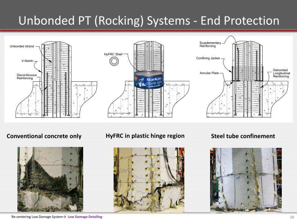
Unbonded PT (Rocking) Systems - End Protection
Conventional concrete only HyFRC in plastic hinge region Steel tube confinement
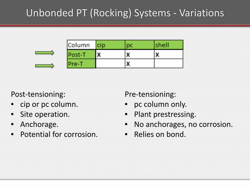
Unbonded PT (Rocking) Systems - Variations
Post-tensioning:• cip or pc column.• Site operation.• Anchorage.• Potential for corrosion.
Pre-tensioning:• pc column only.• Plant prestressing.• No anchorages, no corrosion.• Relies on bond.
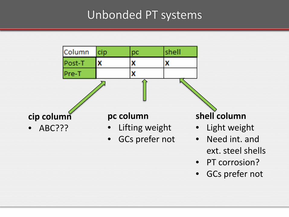
Unbonded PT systems
cip column• ABC???
pc column• Lifting weight• GCs prefer not
shell column• Light weight• Need int. and
ext. steel shells• PT corrosion?• GCs prefer not
Re-centering Low Damage System → Construction Sequence 41
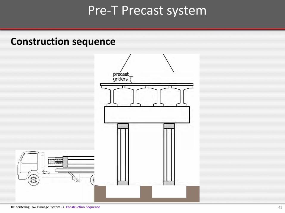
Pre-T Precast system
Construction sequence
42
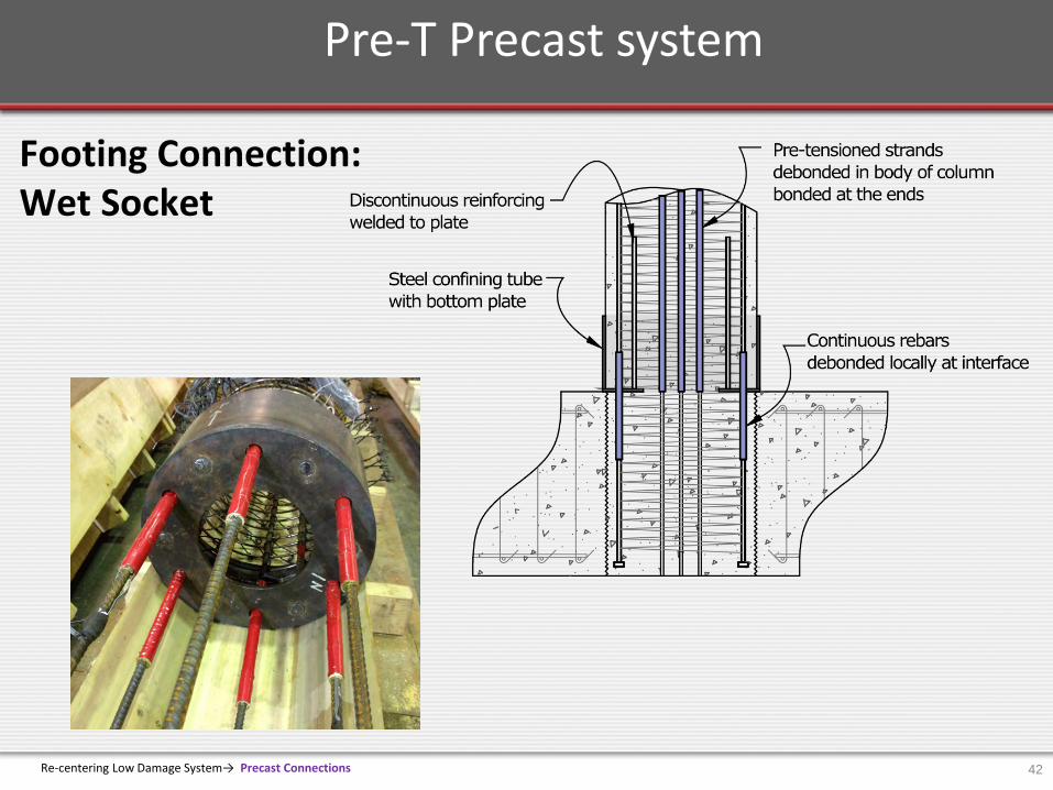
Pre-T Precast system
Re-centering Low Damage System→ Precast Connections
Footing Connection: Wet Socket

Re-centering Low Damage System→ Precast Connections 43
Pre-T Precast system
Cap Beam Connection: Dry Socket & Grouted Duct.

44
Shaking Table Test: 1995 Kobe /Takatori (PGA=0.8g)
Shake Table Test → 2014 PreT Bridge Motion 21C
Pre-T Precast system
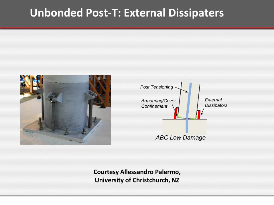
Unbonded Post-T: External Dissipaters
Armouring/CoverConfinement
ABC Low Damage
ExternalDissipators
Post Tensioning
Courtesy Allessandro Palermo,University of Christchurch, NZ
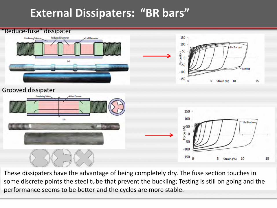
Grooved dissipater
“Reduce-fuse” dissipater
These dissipaters have the advantage of being completely dry. The fuse section touches in some discrete points the steel tube that prevent the buckling; Testing is still on going and the performance seems to be better and the cycles are more stable.
External Dissipaters: “BR bars”
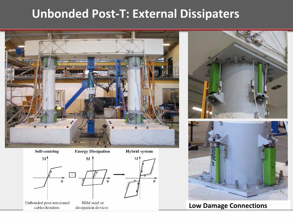
Low Damage Connections
Unbonded Post-T: External Dissipaters
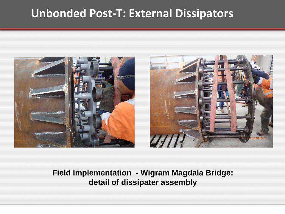
Field Implementation - Wigram Magdala Bridge: detail of dissipater assembly
Unbonded Post-T: External Dissipators
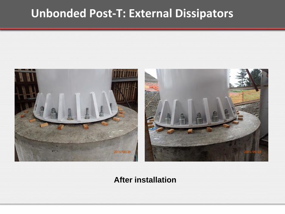
After installation
Unbonded Post-T: External Dissipators
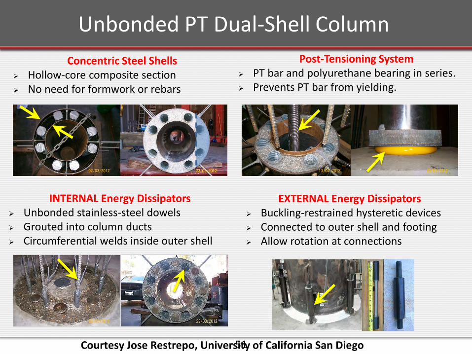
Low damage Unbonded Post-tensioned Dual Shell Columns.
Courtesy Jose Restrepo,University of California San Diego
51
INTERNAL Energy Dissipators Unbonded stainless-steel dowels Grouted into column ducts Circumferential welds inside outer shell
Post-Tensioning System PT bar and polyurethane bearing in series. Prevents PT bar from yielding.
Concentric Steel Shells Hollow-core composite section No need for formwork or rebars
EXTERNAL Energy Dissipators Buckling-restrained hysteretic devices Connected to outer shell and footing Allow rotation at connections
Unbonded PT Dual-Shell Column
Courtesy Jose Restrepo, University of California San Diego

5252
Shake Table Test Specimen
• Cantilever test configuration• Shear span: 96 in. (2.44 m)• Column diameter: 16 in.
(0.41 m)• Outer shell thickness: 0.25
in. (6.4 mm)
Unbonded PT Dual-Shell Column
• PT: single 1.75-in. (46-mm) threaded bar, A722 Gr. 150• Energy dissipators: 8 #3 (9.5-mm) dowels, 316LN Gr. 75 stainless steel• Mortar bed with polypropylene fibers• Matching headed bars • Inertial mass: 53 kips (236 kN)
Low damage Columns with ECC and Shape Memory Allow Bars.
Courtesy Saiid Saiidi,University of Nevada Reno

54
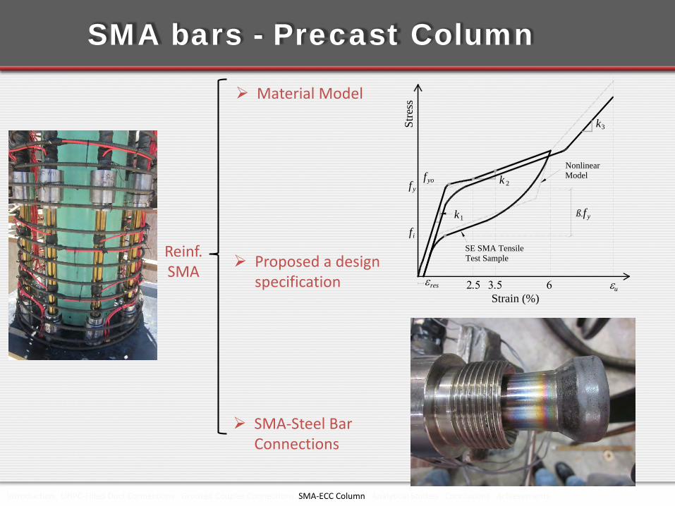
SMA bars - Precast Column
UHPC-Filled Duct Connection
SMA-Reinforced ECC section
Goal:
Develop ABC columns with seismic
performance better than CIP
Headed Coupler Columns tested by Haber et al. (2014), emulative performance
Used eight different materials
Courtesy Saiid Saiidi, University of Nevada Reno
55Introduction UHPC-Filled Duct Connections Grouted Coupler Connections SMA-ECC Column Analytical Studies Conclusions Achievements
Reinf. SMA
Material Model
SMA-Steel Bar Connections
Strain (%)
Stre
ss
k1
k 2fy
ß.f y
k3
SE SMA TensileTest Sample
NonlinearModel
6resεuε
fyo
2.5 3.5
fi
Proposed a design specification
SMA bars - Precast Column
56Introduction UHPC-Filled Duct Connections Grouted Coupler Connections SMA-ECC Column Analytical Studies Conclusions Achievements
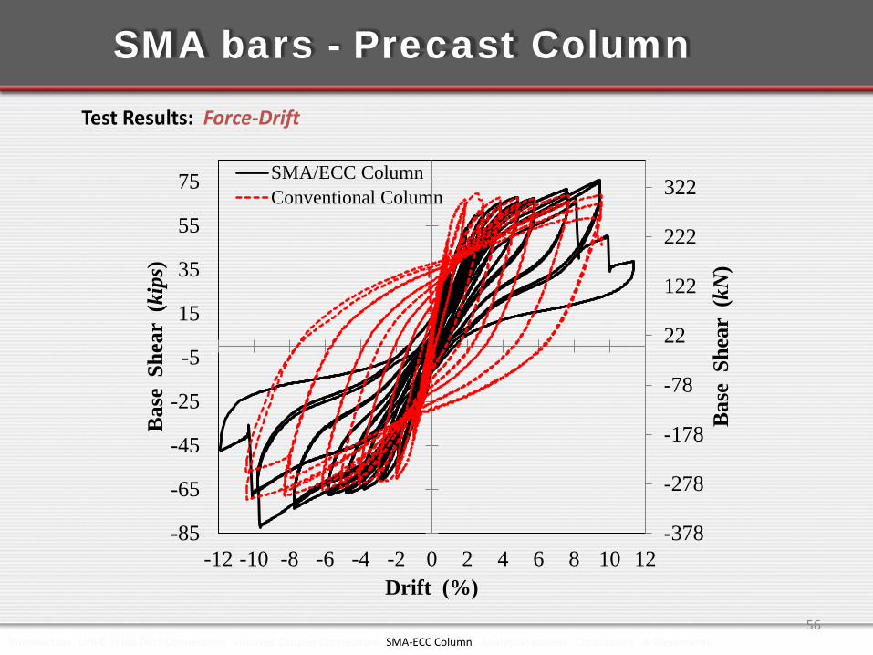
Test Results: Force-Drift
-378
-278
-178
-78
22
122
222
322
-85
-65
-45
-25
-5
15
35
55
75
-12 -10 -8 -6 -4 -2 0 2 4 6 8 10 12
Bas
e S
hear
(kN
)
Bas
e S
hear
(ki
ps)
Drift (%)
SMA/ECC ColumnConventional Column
SMA bars - Precast Column
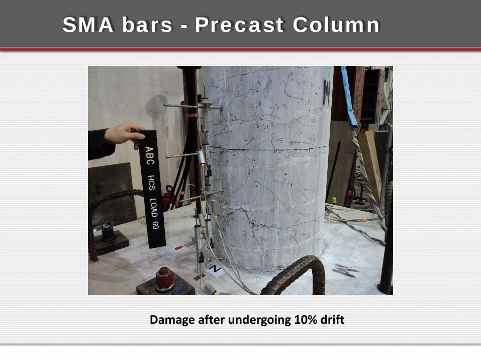
Damage after undergoing 10% drift
SMA bars - Precast Column

SMA bars - Precast Column
SMA bars achieve, in one element:• Re-centering,• Energy dissipation.
Alternative to the unbonded PT/yielding rebar combination.
However:• They are expensive,• Difficult to form or machine.
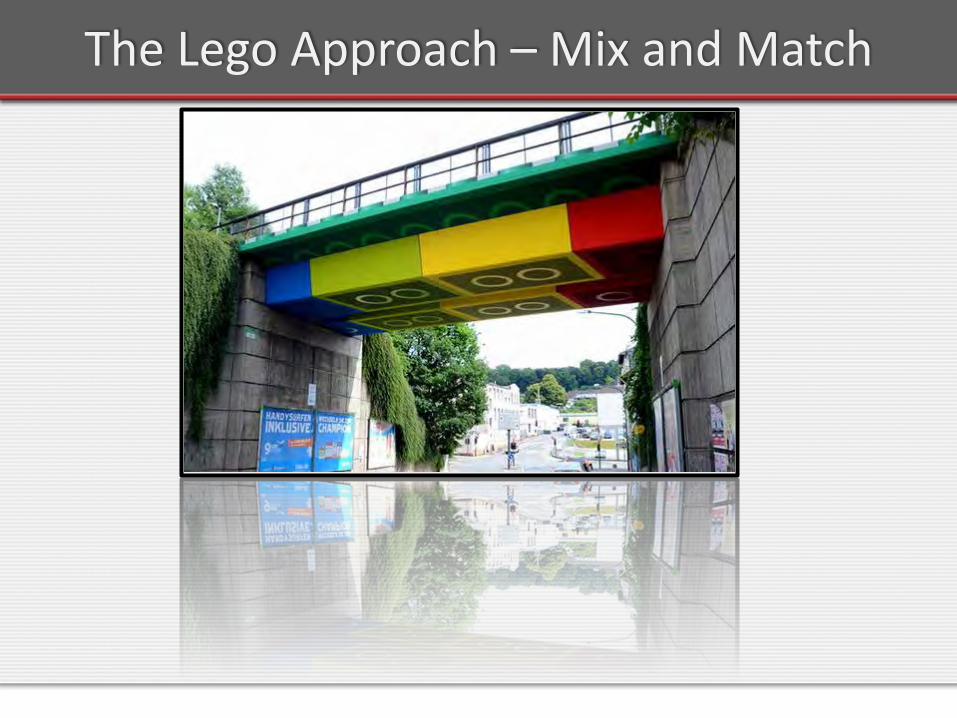
The Lego Approach – Mix and Match

Thank You!
Questions ?