nchrp project 12-102 - bridges.transportation.org€¢ aashto lrfd bridge design specifications •...
TRANSCRIPT

NCHRP Project 12-102
Michael Culmo, PECME Associates, Inc.

Acknowledgements• NCHRP: Waseem Dekelbab• Project Panel
• Ahmad Abu-Hawash – Iowa DOT• Norman P. Marzano Jr. – Rhode Island DOT• Carmen Swanwick – Utah DOT• Dr. Bijan Khaleghi – Washington DOT• William N. Nickas – PCI• Mary Lou Ralls - Consultant• Corey E. Rogers – Michigan DOT• Dr. Maher K. Tadros – Researcher/Consultant• Tim Couples - FHWA
• Project Team• Michael P. Culmo – CME
Associates• Lee Marsh – Berger ABAM• Stuart Bennion – Berger ABAM• John Stanton – UW• Dennis Mertz

NCHRP 12-102Project Overview
• Guide Specification Development• Significant synthesis project• No new research involved• Technology readiness evaluation done for each technology
• Approach:• Not a stand-alone document• Supplement to:
• AASHTO LRFD Bridge Design Specifications• AASHTO Bridge Construction Specifications
• Separate Design and Construction Parts
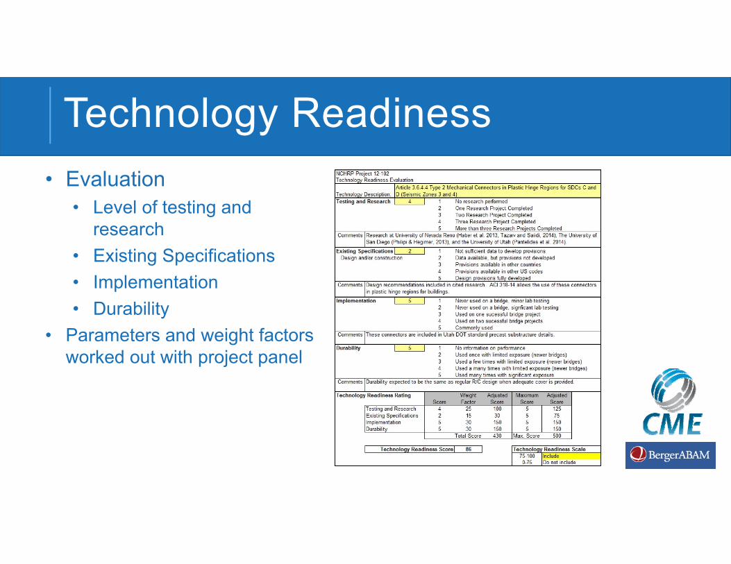
Technology Readiness• Evaluation
• Level of testing and research
• Existing Specifications• Implementation• Durability
• Parameters and weight factors worked out with project panel

Specification Overview• Guide Specification Contents
Part 2: ABC Construction Guide Specifications1. Introduction2. Temporary Works3. Fabrication and Assembly Planning4. Layout and Tolerances5. Concrete Structures6. Steel Structures7. Geosynthetic Reinforced Soil / Integrated
Bridge System
Part 1: ABC Design Guide Specifications1. Introduction2. General Design Provisions3. Design of Prefabricated Elements4. Detailing Requirements5. Durability of ABC Technologies
T-10 Review of New Specifications• Design Specification
• Section 1: Introduction
• Section 2: General Design Provisions
• Shipping and Handling Provisions
• Load Combinations for SPMT and Lateral Slide
T-10 Review of New Specifications• Design Specification
• Section 3: Design of Prefabricated Elements• Majority of specs are based on emulation• Significant seismic provisions (T-3 has reviewed)• Provisions that vary from LRFD
• Lapped hooked and headed bars• UHPC connections• Type 2 Mechanical Connectors• Corrugated Metal Pipe Sockets and corrugated precast sockets• Link slabs

T-10 Review of New Specifications• Design Specification
• Section 4: Detailing Requirements• Tolerances and layout of precast elements
• Reference to NCHRP Project 12-98 guidelines• Section 5: Durability of ABC Technologies
• Detailing recommendations for durability

T-10 Review of New Specifications• Construction Specification
• Section 4: Detailing Requirements• Tolerances and layout of precast elements
• Reference to NCHRP Project 12-98 guidelines• Section 5: Durability of ABC Technologies
• Detailing recommendations for durability

ABC Design and Construction Guide Specifications
• Current Version
Seismic Design with ABC

DESIGN OF PREFABRICATED ELEMENTS
3.4 Seismic Design for Accelerated Bridge Construction
3.5 Prefabricated Element Design
3.6 Connection Design and Detailing
3.7 GRS/IBS
3.8 Accelerated backfill

3.4 SEISMIC DESIGN FOR ABC
3.4.1 Seismic Analysis & Design
3.4.2 Load Path
3.4.3 Seismic Resisting Systems, Elements, & Sub-Systems
3.4.4 Energy Dissipation
3.4.5 Capacity Protection

3.4 SEISMIC DESIGN FOR ABC CONT.
(Zone 1)(Zone 2)(Zone 3)(Zone 4)
Two Codes we are working with currently:
• Force-Based Design AASHTO LRFD Bridge (2014)
• Displacement-Based DesignAASHTO Seismic GS (2011)

3.4 SEISMIC DESIGN FOR ABC CONT.
In high seismic areas inelastic ductility is required; thus clearly all members must have sufficient strength to form the intended plastic mechanism.

3.4 SEISMIC DESIGN FOR ABC CONT.
1. Continuity of load path under load reversals
2. Development of cyclic inelastic deformations
3. Maximum forces (moments) occur where we would like to connect prefabricated elements
4. Certain element/material behaviors may cause rapid loss of cyclic resistance
- Local Buckling- Strain Concentrations
5. Detailing is important!

3.6 Connection Design & Detailing
3.6.1 General
3.6.2 CIP Concrete Closure Joints w/ Lapped Bars
3.6.3 Grout/Concrete Under Footings & Slabs
3.6.4 Mechanical Reinforcing Bar Connectors
3.6.5 Grouted Ducts
3.6.6 Pocket Connections

3.6 Connection Design & Detailing Cont.
3.6.7 Socket Connections
3.6.8 Full Depth Precast Concrete Deck Panel Connections
3.6.9 Link Slabs
3.6.10 Steel Connections
3.6.11 Integral Substructure to Superstructure Connections
3.6.12 Deck Beam Connections

3.6.1 GENERAL CONNECTION DESIGN
ED – Energy Dissipating (Ductile)CP – Capacity Protected (Non-ductile)
Note: In this Example:Moment Continuity at Top and Bottom of Pier

3.6.1 GENERAL CONNECTION DESIGN
Ductile LinkBrittle Links Brittle Links
Force, F F
FdFib
Fd
Weakest Fib
Ductile Behavior, Provided Fd < All Fib
Brittle Behavior, If Any One Fib < Fd
Displacement,
Force

3.6.4 MECHANICAL BAR CONNECTORS
• Viable option for connecting concrete elements• Special detailing requirements for in moderate and high
seismic regionsDefined in ACI-318-14 (Building Code) requirements for structural concrete (Special Moment Frames & Special Structural Walls)
Implied in AASHTO SGS (2011) under “Splicing of Longitudinal Reinforcement in SDCs C & D
• Only Type 2 mechanical permitted in plastic hinge regionsGrouted Sleeve Couplers (GSC) & Headed Reinforcement Couplers (HRC)

3.6.4 ALTERNATIVE CONFIGURATIONS
Grouted Sleeve Coupler (GC)
≤15db
PC Column
Source: Haber et al.,(2013)
Headed Bar Connector (HC)
PC Column
Footing

3.6.4.5 FORCED-BASE DESIGN
• Reduced modification factor
• 0.8 for LMC ≤ 4 dbarl• 0.5 for LMC > 4 dbarl
Length of mechanical coupler (LMC) is limited to LMC ≤ 15 dbarl

3.6.4.6 DISPLACEMENT-BASED DESIGN
L
COLUMN DEFLECTED SHAPE
Rigid FoundationHsp
LspMechanical Couplers
ACTUAL CURVATURE DIAGRAM
IDEALIZED CURVATURE DIAGRAM
Point of Contraflexure
1
= 0.65 for GC= 0.75 for HC

3.6.4.7 DEBONDING OF COLUMN REINF.
Applicable in footing or pier cap when couplers are used
ye bl

Grouted Sleeve Coupler (GC)
High strength or bigger bars
3.6.4 KNOWLEDGE GAPS
• Alternative to GSC and HRC connectors • Assembly tests with coupler under large strain reversals• Could a coupler shift the plastic hinge zone away from
column end

3.6.5 GROUTED DUCTS
• Connect reinforcing bars that projects from one element into a corrugated ducts embedded in receiving member
ASTM A 760(only)
Source: Brenes (2006)

3.6.5 GROUTED DUCTS
Source: Tazarav & Saiidi (2014)
Source: Restrepo et al.,(2011)

3.6.5 GROUTED DUCTS (EMULATIVE)
Grout Bed
Column
PC Pier Cap
Grouted Duct
Source: Restrepo et al.,(2011)

3.6.5.1 DEVELOPMENT LENGTH
Bedding layer T
Bar-to-grout bond
Duct-to-concrete bond
0
5
10
15
20
25
30
35
40
4 5 6 7 8 9 10 11 12 13 14 15
l ac/d
bl
f'cg (ksi)
NCHRP 681 (2011)AASHTO Guide Specs (2011)Proposed
0.67

3.6.5 KNOWLEDGE GAPS
• Cyclic bond behavior of bars embedded in ducts• Effect of confinement materials on bond behavior• Bond characteristics of PT ducts or other materials

3.6.6 POCKET CONNECTIONS
• Column with projecting reinforcement and a receiving precast footing or pier cap with a corrugated steel-pipe-formed pocket
ASTM A 760(only)
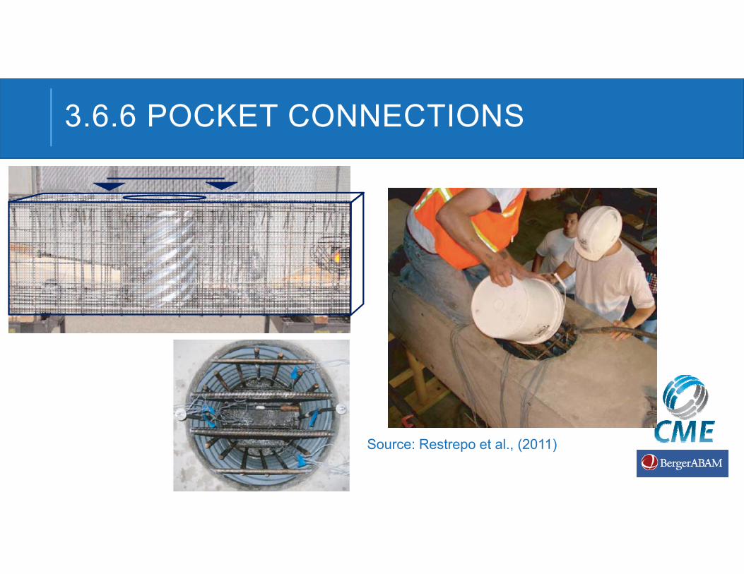
3.6.6 POCKET CONNECTIONS
Source: Restrepo et al., (2011)

3.6.6 POCKET CONNECTIONS
PC Cap Beam
Steel Pipe
Bedding Layer
CIP Fill (PC Pocket)
Column Long. Reinf.
Column
Source: Restrepo et al.,(2011)

0
5
10
15
20
25
30
35
40
45
4 5 6 7 8 9 10 11 12
l ac/d
bl
f'c (ksi)
NCHRP 681 (2011)
AASHTO Guide Specs (2011)
Proposed
3.6.6.3 DEVELOPMENT LENGTH
Bedding layer T
Bar-to-concrete bond
Tube-to-concrete bond

3.6.6.4 CORRUGATED PIPE THICKNESS
Fp
a
D’cp
FH
D’cp
(b) Corrugated Steel Pipe
(a) Spiral
s
=
, 0.060 in)
Set:
Solve:
0.11 for SDCs A & B and Zones 1 & 2
Max .
, 0.40 For Zones 3 & 4
Calculated for SDCs C & D
=
⍺
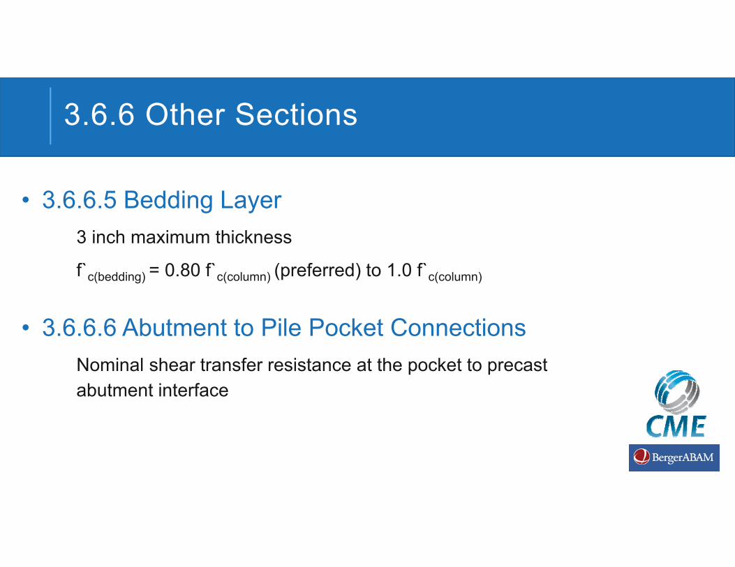
3.6.6 Other Sections
• 3.6.6.5 Bedding Layer3 inch maximum thickness
f`c(bedding) = 0.80 f`c(column) (preferred) to 1.0 f`c(column)
• 3.6.6.6 Abutment to Pile Pocket ConnectionsNominal shear transfer resistance at the pocket to precast abutment interface

3.6.6 KNOWLEDGE GAPS
• No pullout tests on actual configuration (pocket formed by corrugated tube) available.
• Corrugated pipe thickness to be investigated as test variable
• Need to investigate other types of pocket forms

3.6.7 SOCKET CONNECTIONS
• Embedment of precast column or pile into receiving element
a) Wet (cast-in-place)
Embedded ColumnCIP Footing
b) Formed (precast)
Embedded Column
Grout or Concrete Pour
PC Cap
• Socket can be:

3.6.7 SOCKET CONNECTIONS
Source: Marsh et al. (2013)
COLUMN IN CIP FOOTING
Source: Tran et al. (2013)
CIP Shaft
PC Column
COLUMN IN OVERSIZED SHAFT

3.6.7 SOCKET CONNECTIONS
CFT
Annular Plate
CIP PIER CAP
Eastbound Nalley Valley (WSDOT)

3.6.7 SOCKET CONNECTIONS (EMULATIVE)
-10 -5 0 5 10-400
-300
-200
-100
0
100
200
300
400
Drift [%]
Mom
ent [
kN-m
]
Source: Haraldsson et al., (2013)
Embedded ColumnCIP Footing

3.6.7.2 SOCKET IN CIP FOOTING
Dc
if Le≤1.5DcIntentionally roughening (0.25” ) is required
Le ≥ 1.0 Dc
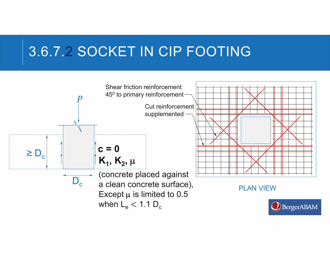
3.6.7.2 SOCKET IN CIP FOOTING
c = 0≥ Dc
Dc
K1, K2, (concrete placed against a clean concrete surface), Except is limited to 0.5 when Le 1.1 Dc
Shear friction reinforcement 450 to primary reinforcement
PLAN VIEW
Cut reinforcement supplemented
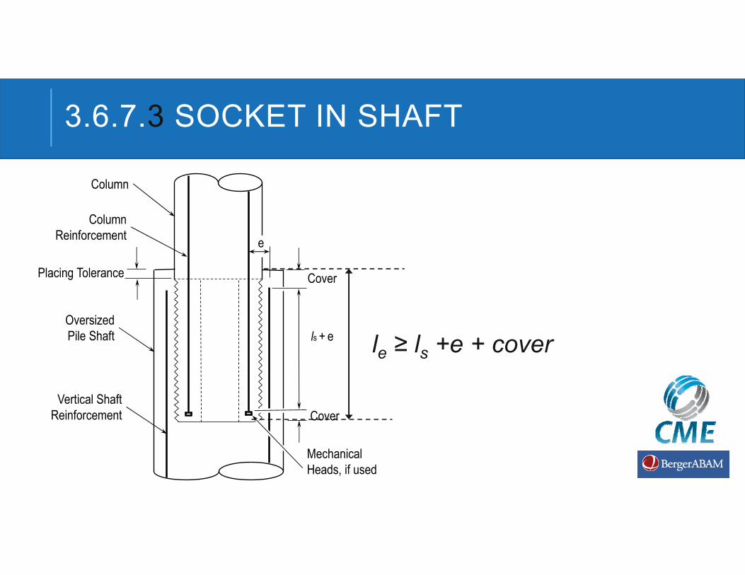
3.6.7.3 SOCKET IN SHAFT
Column
Oversized Pile Shaft
Vertical Shaft Reinforcement
ls + e
Mechanical Heads, if used
Cover
e
Column Reinforcement
Cover
Placing Tolerance
le ≥ ls +e + cover

3.6.7.3 SOCKET IN SHAFT
Spiral/Hoops Requirement
A
B1’-0”
(k = 0.5)
(k = 1.0)
(k = 2.0)(k = 1.0)
C
A
B
C
Locationle
Le /2
Le /2
cover

3.6.7.3 SOCKET IN SHAFT

3.6.7.4 SOCKET IN PC ELEMENT
Socket (Corrugated Steel Pile)
Dc
≥ 0.25 Hp
≥ 4.0 in.
Socket Spiral/Hoop
>110
3 in. max.
Bundled Bars

3.6.7.5 CFT IN SOCKET
CFT
Annular Plate(welded)
4 0.12 2
41.2
0.19 2
CIP FOOTING
16t 8t
Do
Dcde ≥ Dc
/2.51.5
Tube Thickness (t)

3.6.7.5 CFT IN SOCKET
0.8
0.9
1.0
1.1
1.2
1.3
1.4
36 48 60 72
l e/Dc
Dc(in.)
(t = 1.0 in., 5 , 65
41.2
0.19 2

3.6.7 KNOWLEDGE GAPS
• Determine the role of cohesion and the effect of concrete shrinkage in wet socket connection.
• Sacrificial tube to form the portion of the column embedded into the oversized shaft as substitute for spiral/hoops
• Vertical load transfer characteristics and bond behavior at the concrete-corrugated pipe interface of socket

3.6.11 INTEGRAL CONNECTIONS
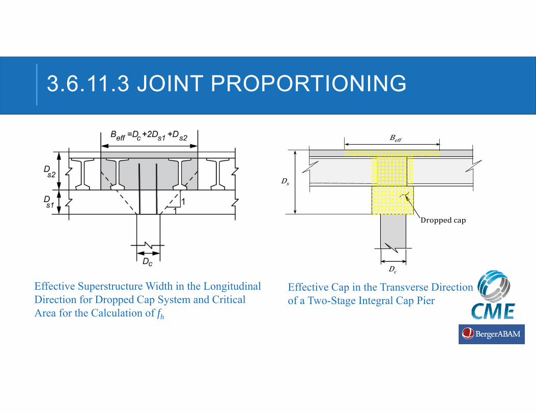
3.6.11.3 JOINT PROPORTIONING
Effective Superstructure Width in the Longitudinal Direction for Dropped Cap System and Critical Area for the Calculation of fh
Ds
Dc
Droppedcap
Beff
Effective Cap in the Transverse Direction of a Two-Stage Integral Cap Pier

3.6.11.3 JOINT PROPORTIONING CONT.
Critical Area for the Calculation of vjv
Critical Area for the Calculation of vjv

3.6.7 KNOWLEDGE GAPS
• Determine the role of cohesion and the effect of concrete shrinkage in wet socket connection.
• Sacrificial tube to form the portion of the column embedded into the oversized shaft as substitute for spiral/hoops
• Vertical load transfer characteristics and bond behavior at the concrete-corrugated pipe interface of socket