universit a degli studi della calabria
TRANSCRIPT

Universita degli Studi della Calabria
Faculty of Engineering
Master in Computer Engineering
Master Thesis
A lightweight framework for task oriented
programming of signal processing
applications on wireless sensor networks
Supervisor Candidate
Prof. Giancarlo Fortino Stefano Galzarano
Matr. 113585
Academic Year 2009-2010


Alla mia famiglia,
per l’amore dimostratomi
e per il fondamentale
supporto (non solo morale) datomi
durante questi lunghi anni di studio.
Al mio ”amoruzzo” Caterina,
che mi e stata sempre vicina,
specialmente nei momenti difficili,
e ha contribuito al raggiungimento
di un cosı importante obiettivo.


Abstract
Wireless sensor networks (WSNs) represent a form of pervasive and ubiq-uitous computing system. They have been successfully used in many differ-ent application areas and in future they will play an increasingly importantrole. It is not unreasonable to expect that sensor networks will be a funda-mental part of our life, with profound impact on our daily activities.
However, development of applications for WSNs is an extremely chal-lenging and error-prone task since it requires programming individual nodesusing low-level APIs. This implies knowledge from many different areas,ranging from sensor nodes hardware and radio communication to high-levelconcepts concerning the final user applications. The lack of easiness in pro-gramming WSNs represents the main obstacle to the current wide diffusionof this technology.
The need for high-level programming approaches is quite evident andcurrently many frameworks and middlewares have been proposed. However,many of the existent solutions are not suitable for application domains (i.e.context recognition, health monitoring, medical assistance, etc) requiringcollaborative sensor data processing in the network.
This thesis proposes a novel framework enabling intensive distributedsignal processing-based applications. In particular, the framework providesan intuitive application design model based on the task-oriented approachand supported by an high-level specification language. The framework de-sign and implementation based on the software layering approach allowsfast porting to every C-like sensor platform, whereas its modular softwarearchitecture allows to easily extend the functionalities and the services pro-vided to developers. Finally, the framework has been fully implemented andtested on TinyOS sensor platforms.
iv

Sommario
Le reti di sensori wireless (wireless sensor networks, WSNs) rappresenta-no una forma di sistema computazionale pervasivo e ubiquo. Esse sono stateutilizzate con successo in molte aree applicative e in futuro giocheranno unruolo sempre piu importante. Non e irragionevole aspettarsi che le reti disensori saranno una parte fondamentale della nostra vita, con un impattoprofondo sulle nostre attivita giornaliere.
Comunque, sviluppare applicazioni per le WSNs e un lavoro estremamen-te impegnativo e propenso ad errori, dal momento che richiede la program-mazione dei singoli nodi utilizzando delle API di basso livello. Cio implicala necessita di possedere conoscenze riguardo diverse aree, che spaziano dall’hardware e comunicazione radio del nodo sensore fino ai concetti di altolivello riguardanti le applicazioni dell’utente finale. La mancanza di facilitanel programmare le WSNs rappresenta il principale ostacolo per un’ampiadiffusione di tale tecnologia.
La necessita di approcci di programmazione di alto livello e abbastanzaevidente ed attualmente molti framework e middleware sono stati proposti.Comunque, molte delle soluzioni esistenti non sono adatte per quei dominiapplicativi (come il context recognition, il monitoraggio della salute, l’as-sistenza medica, e molti altri) che richiedono un’elaborazione collaborativadei dati provenienti dai sensori della rete.
Questa tesi propone un nuovo framework per consentire lo sviluppo diapplicazioni distribuite per l’elaborazione intensiva di segnali. In particola-re, tale framework fornisce, per la progettazione di applicazioni, un modellointuitivo basato su un approccio task-oriented (orientato ai task), e suppor-tato da un linguaggio di specifica di alto livello. Inoltre, la progettazione el’implementazione basata sull’approccio del software layering, consente unveloce porting per poter essere utilizzato su qualsiasi piattaforma di sensoribasata su linguaggio C. Inoltre, la sua architettura software di tipo modularepermette di estendere facilmente le funzionalita ed i servizi offerti allo svi-luppatore. Infine, il framework e stato interamente implementato e testatosu sensori basati sul sistema operativo TinyOS.


Contents
Contents vii
List of Figures xi
List of Abbreviations xiv
1 Introduction 1
1.1 Research context . . . . . . . . . . . . . . . . . . . . . . . . . 4
1.2 Thesis motivations . . . . . . . . . . . . . . . . . . . . . . . . 5
1.3 Thesis objectives and contributions . . . . . . . . . . . . . . . 6
1.4 Outline . . . . . . . . . . . . . . . . . . . . . . . . . . . . . . 8
2 WSN applications development 9
2.1 Application design aspects . . . . . . . . . . . . . . . . . . . . 9
2.1.1 Differences from traditional distributed systems . . . . 13
2.2 Operating system for sensor nodes . . . . . . . . . . . . . . . 14
2.2.1 Differences from general-purpose OSs . . . . . . . . . 15
2.2.2 Operating systems overview . . . . . . . . . . . . . . . 16
2.3 Need for programming abstractions . . . . . . . . . . . . . . . 19
vii

CONTENTS
2.3.1 Limitations on developing over an OS . . . . . . . . . 20
2.3.2 Abstraction requirements . . . . . . . . . . . . . . . . 22
2.3.3 Bottom-up and top-down methodologies . . . . . . . . 23
2.4 Programming paradigms and Middleware . . . . . . . . . . . 24
2.5 The programming abstraction approach . . . . . . . . . . . . 27
2.5.1 Database model . . . . . . . . . . . . . . . . . . . . . 28
2.5.2 Macroprogramming model . . . . . . . . . . . . . . . . 29
2.5.3 Agent-based model . . . . . . . . . . . . . . . . . . . . 31
2.6 The programming support approach . . . . . . . . . . . . . . 33
2.6.1 Event-based model . . . . . . . . . . . . . . . . . . . . 33
2.6.2 Application-driven model . . . . . . . . . . . . . . . . 34
2.6.3 Virtual machine . . . . . . . . . . . . . . . . . . . . . 35
3 Related work 37
3.1 SPINE . . . . . . . . . . . . . . . . . . . . . . . . . . . . . . . 39
3.1.1 Description . . . . . . . . . . . . . . . . . . . . . . . . 40
3.1.2 Software architecture . . . . . . . . . . . . . . . . . . . 41
3.1.3 Communication and application deployment . . . . . . 42
3.1.4 An example of application . . . . . . . . . . . . . . . . 43
3.2 Titan . . . . . . . . . . . . . . . . . . . . . . . . . . . . . . . 44
3.2.1 Overall description . . . . . . . . . . . . . . . . . . . . 44
3.2.2 Architecture . . . . . . . . . . . . . . . . . . . . . . . 45
3.2.3 Application configuration and execution . . . . . . . . 46
3.3 ATaG: Abstract Task Graph . . . . . . . . . . . . . . . . . . 48
3.3.1 Application definition . . . . . . . . . . . . . . . . . . 49
3.3.2 Programming syntax . . . . . . . . . . . . . . . . . . . 49
3.3.3 Application deployment . . . . . . . . . . . . . . . . . 52
3.3.4 DART: the Data-driven ATaG Runtime . . . . . . . . 54
viii

CONTENTS
3.4 Considerations . . . . . . . . . . . . . . . . . . . . . . . . . . 55
4 Framework design and implementation 57
4.1 Framework overview . . . . . . . . . . . . . . . . . . . . . . . 58
4.1.1 The task-oriented approach . . . . . . . . . . . . . . . 62
4.1.2 Main characteristics . . . . . . . . . . . . . . . . . . . 63
4.1.3 Network topology . . . . . . . . . . . . . . . . . . . . 66
4.2 Definition language . . . . . . . . . . . . . . . . . . . . . . . . 67
4.2.1 Tasks . . . . . . . . . . . . . . . . . . . . . . . . . . . 68
4.2.2 Connections . . . . . . . . . . . . . . . . . . . . . . . . 75
4.3 Node-side architecture . . . . . . . . . . . . . . . . . . . . . . 76
4.3.1 Sensing Module . . . . . . . . . . . . . . . . . . . . . . 79
4.3.2 Communication Module . . . . . . . . . . . . . . . . . 81
4.3.3 Timers Module . . . . . . . . . . . . . . . . . . . . . . 82
4.3.4 Memory Module . . . . . . . . . . . . . . . . . . . . . 84
4.3.5 Task Module . . . . . . . . . . . . . . . . . . . . . . . 88
4.4 Coordinator-side architecture . . . . . . . . . . . . . . . . . . 93
4.5 Communication protocol . . . . . . . . . . . . . . . . . . . . . 97
4.6 Application development cycle . . . . . . . . . . . . . . . . . 100
4.7 A case study: human activity recognition . . . . . . . . . . . 105
5 Evaluation 108
5.1 Computational performance . . . . . . . . . . . . . . . . . . . 109
5.2 Data transmission performance . . . . . . . . . . . . . . . . . 112
5.3 Memory usage . . . . . . . . . . . . . . . . . . . . . . . . . . 116
6 Conclusion and future work 121
6.1 Future work . . . . . . . . . . . . . . . . . . . . . . . . . . . . 124
ix

CONTENTS
Bibliography 126
x

List of Figures
2.1 Layers of abstraction for WSN application development. . . . 25
3.1 SPINE software architecture. . . . . . . . . . . . . . . . . . . 41
3.2 SPINE messages list. . . . . . . . . . . . . . . . . . . . . . . . 42
3.3 Example of Titan application. . . . . . . . . . . . . . . . . . . 45
3.4 Modules of the Titan architecture. . . . . . . . . . . . . . . . 45
3.5 Task subnetworks allocation of a Titan Application. . . . . . 48
3.6 Environment monitoring application. . . . . . . . . . . . . . . 51
3.7 ATaG application development. . . . . . . . . . . . . . . . . . 53
3.8 DART: Data-driven ATaG runtime system. . . . . . . . . . . 54
4.1 Example of a task-oriented application. . . . . . . . . . . . . 59
4.2 Application example having tasks instantiated on different
nodes. . . . . . . . . . . . . . . . . . . . . . . . . . . . . . . . 61
4.3 The Software Layering approach for developing the framework. 64
4.4 WSN topology supported by the framework. . . . . . . . . . . 67
4.5 Data-Processing Task Description. . . . . . . . . . . . . . . . 68
4.6 Data-Routing Task Description. . . . . . . . . . . . . . . . . . 68
4.7 TimingTask Description. . . . . . . . . . . . . . . . . . . . . . 71
xi

LIST OF FIGURES
4.8 SensingTask Description. . . . . . . . . . . . . . . . . . . . . . 72
4.9 ProcessingTask Description. . . . . . . . . . . . . . . . . . . . 72
4.10 TransmissionTask Description. . . . . . . . . . . . . . . . . . 73
4.11 StoringTask Description. . . . . . . . . . . . . . . . . . . . . . 73
4.12 LoadingTask Description. . . . . . . . . . . . . . . . . . . . . 73
4.13 SplitTask Description. . . . . . . . . . . . . . . . . . . . . . . 74
4.14 AggregationTask Description. . . . . . . . . . . . . . . . . . . 74
4.15 HistoricalAggregationTask Description. . . . . . . . . . . . . . 75
4.16 Connection Description. . . . . . . . . . . . . . . . . . . . . . 75
4.17 Software architecture of the node-side part of the framework. 77
4.18 The packet header adopted by the framework. . . . . . . . . . 82
4.19 Software architecture of the coordinator-side part of the frame-
work. . . . . . . . . . . . . . . . . . . . . . . . . . . . . . . . . 95
4.20 The framework protocol stack layers. . . . . . . . . . . . . . . 97
4.21 Packet definition. . . . . . . . . . . . . . . . . . . . . . . . . . 98
4.22 Task Creation message. . . . . . . . . . . . . . . . . . . . . . 99
4.23 Connections Creation message. . . . . . . . . . . . . . . . . . 100
4.24 Init and Start message. . . . . . . . . . . . . . . . . . . . . . 100
4.25 Node Application Ready message. . . . . . . . . . . . . . . . 101
4.26 Sensor Data message. . . . . . . . . . . . . . . . . . . . . . . 101
4.27 Sensor to Sensor Data message. . . . . . . . . . . . . . . . . . 102
4.28 Application running on the waist node. . . . . . . . . . . . . 106
4.29 Application running on the thigh node. . . . . . . . . . . . . 107
4.30 The ”waist” application distributed on two nodes. . . . . . . . 107
5.1 ProcessingTask execution time, with the ”Min” function as
parameter. . . . . . . . . . . . . . . . . . . . . . . . . . . . . . 113
xii
LIST OF FIGURES
5.2 ProcessingTask execution time, with the ”Mean” function as
parameter. . . . . . . . . . . . . . . . . . . . . . . . . . . . . . 114
5.3 ProcessingTask execution time, with the ”Standard deviation”
function as parameter. . . . . . . . . . . . . . . . . . . . . . . 115
5.4 ProcessingTask execution time, with the ”Vector magnitude”
function as parameter. . . . . . . . . . . . . . . . . . . . . . . 116
5.5 ProcessingTask execution time, with the ”Pitch and Roll”
function as parameter. . . . . . . . . . . . . . . . . . . . . . . 117
5.6 Packet fragments required for transmitting user data. . . . . 118
5.7 Comparison between the amount of user data to be transmit-
ted and the extra overhead needed for packets fragmentation. 118
5.8 Time needed to transmit user data among tasks. . . . . . . . 119
5.9 Program memory usage. . . . . . . . . . . . . . . . . . . . . . 119
5.10 Program memory usage (details for the platform-dependent
components). . . . . . . . . . . . . . . . . . . . . . . . . . . . 120
xiii

List of Abbreviations
API Application Programming Interface
ATaG Abstract Task Graph
BSN Boby Sensor Network
CORBA Common Object Request Broker Architecture
FIFO First In First Out
GSM Global System for Mobile Communications
HW Hardware
MAPS Mobile Agent Platform for Sun SPOTs
ONC RPC Open Network Computing Remote Procedure Call
OS Operating System
QoS Quality of Service
RPC Remote Procedure Call
SQL Structured Query Language
xiv

LIST OF ABBREVIATIONS
SW Software
VM Virtual Machine
WBSN Wireless Boby Sensor Network
WSN Wireless Sensor Network
xv


Chapter 1Introduction
Wireless sensor networks (WSNs) [60, 14, 42] are collection of tiny, low-
cost devices with sensing, computing, storing, communicating and possibly
actuating capabilities. Every sensor node is programmed to interact with
the other ones and with its environment, constituting a unique distributed
and cooperative system used for reaching a global behavior and result.
Thanks to wireless communication capabilities, sensor networks succeed
for their flexibility which make sensors deployment and maintenance a very
easy and fast task, with limited added costs. In fact, given a large number
of devices, wiring not only is a very expensive approach but also it prevents
them from being mobile and close to the physical phenomenon of interest.
WSNs are a powerful technology for supporting a lot of different real-
world applications, and for a demonstration it is worth noting that in the last
decade this new technology has emerged in a wide range of different domains
including health-care, environment and infrastructures monitoring, smart
home automation, emergence management, and military support, showing
a great potential for numerous other applications [2, 3].
Nowadays, sensor platforms are becoming cheaper and cheaper and is
1

CHAPTER 1. INTRODUCTION
not unreasonable to expect that in the imminent future sensor networks
will be a fundamental part of our life, with profound impact on our daily
activities. It is feasible to imagine that this technology will be integrated
with the global information infrastructure so that the whole world will be
covered with these kind of pervasive computing systems. Furthermore, their
employment will lead to new business opportunities, in a similar way as it
is happening with Internet and the Web.
Unfortunately, designing such a network is not an easy work because it
implies knowledges from many different areas, ranging from low-level aspects
of the sensor nodes hardware and radio communication to high-level concepts
concerning final user applications [28].
Moreover, WSN technology still has many open challenges:
• Limited hardware resources: each node has a scarce power supply,
limited computational capability and constrained memory.
• Limited support for networking : each node is generally part of a meshed
dynamic topology network where they have both routing and appli-
cation hosting functions. Furthermore, there are no universal routing
protocols.
• Limited support for application development : global application be-
havior and functions must be actually coded and specified locally into
every node-level environment. The gap between sensor platforms (both
hardware and OS) and user applications is hard to fill and a standard
approach has not been defined yet.
All the aforementioned limitations represent big obstacles to the wide
diffusion of this technology, but probably the most decisive one from the in-
2

CHAPTER 1. INTRODUCTION
dustrial point of view is the lack of easiness in programming them. Overcom-
ing this problem by providing a powerful yet simple software development
tool is a fundamental step for better exploiting current sensor platforms.
This will contribute to a more rapid expansion of WSNs, that in turn will
lead to a progressively availability of new sensor node architectures with
many improved characteristics ranging from battery autonomy to process-
ing performance. These new platforms will allow to satisfy the more and
more growing needs requested by real contexts and will enable more sophis-
ticated applications. Hence, one of the actual limitations for an effective
exploitation of sensor networks is the time needed for applications design,
development and testing.
For the above reasons, the topic we are interested to is relative to the
programming issues, and this thesis has been conceived for looking into the
problems programmers have to tackle during the hard task of developing
software on a wireless sensor network. It also aims at providing all the
motivations that have led current researchers to concentrate their efforts
in formulating new application design approach and new implementation
methodologies.
Furthermore, on the basis of the arguments discussed in the following
of this thesis, a new framework for a rapid and effective application devel-
opment is presented. It aims at defining all functions and properties of the
applications in an accurate way by providing users an intuitive and straight-
forward design model based on a task-oriented approach and relying on a
simple but formal high-level language.
At the same time the strong expressive ability of the adopted model
allows using this framework for most of the applications conceived to be
executed on a WSN.
3

CHAPTER 1. INTRODUCTION
1.1 Research context
Like any other embedded system, a first approach for developing an
application is to code it above the node-level operating system, so that the
programmers have to directly handle all resources on the node. Furthermore,
they have to cope with the problems of manually dealing with inter-node
communication. Using such an approach, programming sensor networks
is a very difficult, challenging task not only due to the complexity of the
applications but also due to the sensor node constraints such as scarce power
supply, limited computational resources and constrained memory.
Another important factor to take into account is that WSN program-
ming and deployment involve significant manpower and it is known that
the human resource is relatively costly depending on the time needed for
the completion of the aforementioned tasks and on the individual skills of
developers.
Moreover, application developers are typically domain knowledge special-
ists, rather than programming and networking experts and then providing
appropriate programming abstractions to support these persons in writing
applications is one of the key challenges for WSN.
From the above motivations, it is quite evident that the middleware
approach [49] can be adopted for addressing these programming problems
and supporting users in a fast and effective development of applications.
Middleware usually resides below the application level and on top of the
operating systems and network protocols, hiding details of the lower levels.
Its basic functions [61] are (1) to provide a standard system service to easily
deploy current and future applications and (2) to offer mechanisms for an
adaptive and efficient utilization of system resources. In [61, 48, 22, 36]
design principles for developing WSN middleware are suggested.
4

CHAPTER 1. INTRODUCTION
In the last decade many middleware solutions have been proposed, differ-
ing on the basis of the model assumed for providing the high-level abstrac-
tions, but no one can be considered the best. In fact, depending on specific
tasks and/or contexts, certain solutions could result better choices than
others. A discussion on the different programming paradigms and their rep-
resentative middleware software is reported in section 2.4, whereas surveys
of various proposed solutions in literature can be found in [55, 22, 24, 47].
1.2 Thesis motivations
As it has been previously stated, nowadays high-level programming ap-
proaches are one of the most emerging research area in the context of WSN.
On the basis of the literature so far, it emerges that none of the proposed
application development methodologies can be considered the predominant
one. Most of them has peculiar features specifically conceived for particular
application domains but lacks in characteristics useful for more general-
purpose uses.
For example, the analysis of the current situation highlight that many
middlewares are based on a data centric approach providing high-level ser-
vices for data aggregation and querying. Middlewares developed on this
approach, like the database model presented in section 2.5.1, provide in-
terfaces for data collection but, unfortunately they do not provide general
purpose distributed computation so that they are not suitable for application
domains requiring more sophisticated collaborative sensor data processing
management in the network. In fact, these middlewares do not allow an
explicit data flow processing which could be an important missing char-
acteristic for many applications n the future, such as context recognition
[19, 32], health monitoring, and medical assistance [32, 9, 58, 59], which will
5

CHAPTER 1. INTRODUCTION
become crucial in the future.
Some others middlewares based on different programming models, such
as macroprogramming (section 2.5.2), agent-based (section 2.5.3), and vir-
tual machines (section 2.6.3) support more processing capabilities but, even
though they provide very useful programming abstractions, developers have
to write some code for specifying application behavior and details and also
user program execution performance suffers from the overheads generated
by the heavy underlying middleware runtime system.
These reasons are valid motivations to presume that a new software
framework may be a requirement for enabling intensive distributed signal
processing-based applications by offering users the instruments for develop-
ing them in a high-level visual language appositely designed for avoiding the
need of writing code.
1.3 Thesis objectives and contributions
The two main purposes of this thesis are (1) to provide a better un-
derstanding of the current research issues in the field of sensor networks
programming and (2) to present a new framework aiming at ease and speed
up WSN application development.
In particular, the framework designed and implemented in this work tries
to fulfill three desirable requirements:
• the need for methodologies and models for translating high-level spec-
ifications into an actual executable application running on a real wire-
less sensor network;
• the need for a tool that allow building applications without any kind
of deep knowledge about the specific sensor platforms adopted;
6

CHAPTER 1. INTRODUCTION
• the need for a tool able to deploy a same application on different sensor
architectures in a transparent way for the developer.
The first point encloses the main challenges for researchers concerning
WSN software development. To date, various approaches for a rapid and
less error prone applications definition have been presented in literature.
Most of them are influenced by ideas originally proposed for other fields
like traditional distributed computing, but this new technology necessitates
further semantic extensions and in many aspects requires conceiving new
ad-hoc paradigms.
The second point is an essential requirement for a rapid and broad spread
of WSNs in all potential application domains. In fact, a domain expert
would prefer to build its own application with no necessary background in
low-level programming or without the need for consulting a skilled sensor
node programmer.
Concerning the third requirement, to date most of the applications has
focused on homogeneous wireless sensor networks where all nodes have a
same hw/sw architecture. But, this is a limiting factor for multi-platform
applications, specially considering that at the present low-cost mass produc-
tion has permitted the development of a wide variety of sensors and that it
could be very frequent to have more than one type of node integrated into
a single WSN.
On the basis of all the previous considerations, a task-oriented ap-
proach has been chosen to be the base for the application definitions mod-
eling and consequently for the underlaying application execution framework
runtime. In fact, this modeling language is shown to be simple, but expres-
sive enough to become the preferred method used for describing a typical
7

CHAPTER 1. INTRODUCTION
distributed application aimed to data and signal processing. And at the
same time, its intrinsic characteristics allow the required reusability and
fast reconfiguration of the application to be satisfied. The details and the
benefits in using the task-oriented paradigm are presented in section 4.1.1.
1.4 Outline
This thesis is structured as follows. Chapter 2 reports a detailed dis-
cussion on the main issues regarding WSN programming: starting from
challenges and difficulties in creating applications, it illustrates why is very
important to provide some kind of programming abstraction for overcoming
many problems developers have to tackle with. Afterwards, the main mid-
dleware approaches are categorized and described in their functionalities.
More detailed descriptions about some chosen interesting middleware soft-
wares are provided in Chapter 3. In Chapter 4 a new framework for easing
and speeding up application programming is proposed. First of all, the sup-
porting high-level description language is shown in all its details, highlighting
its expressiveness in defining distributed applications behavior through the
task-oriented approach. Moreover, the software architecture design of the
framework and some of the techniques and solutions adopted for its task
execution runtime system implementation are reported. A functional evalu-
ation of the middleware in a real application context is reported in Chapter
5 which also includes some performance evaluation. Finally, Chapter 6 re-
marks the conclusions illustrating also the future works for improving and
extending the current framework capabilities.
8

Chapter 2WSN applications development
In this chapter, main concepts related to WSN programming methods are
discussed, entering into specific issues concerning models and instruments
used by programmers for sensor applications development.
Moreover, a comprehensive knowledge of WSN contexts and sensor nodes
execution environments is necessary to understand which problems and ques-
tions have to be tackled for conceiving suitable design methodologies and
implementation approaches useful for an effective and fast building of dis-
tributed application for sensor networks.
2.1 Application design aspects
Currently, most of the applications for wireless sensor networks are re-
search prototypes or are expressly developed to be tailored for a specific
purpose, following an application-specific approach. Moreover, a WSN ar-
chitecture able to embrace a wide range of different applications is still miss-
ing, because it is very difficult to develop a unique open system that allows
to be adopted in vastly diverse context domains.
9

CHAPTER 2. WSN APPLICATIONS DEVELOPMENT
In [46] authors identify many aspects of the characteristics of sensor net-
works that developers have to take into account as a supporting guide lines
for applications/middleware design. They introduce the notion of sensor
network design space as a conceptual base for the development of flexible
software frameworks capable to meet different application requirements. In
such a design space every dimension consists of the following characteristic
aspects.
Deployment: deployment involves many different ways for physical place-
ment of the sensor nodes into the environment of interest. Sensors may
be placed randomly disseminating them with an irregular arrangement
or they may be placed in specific chosen points. Furthermore deploy-
ment task may take place only one time or it may be a continuous
process with addition/substitution of new nodes.
Mobility: mobility has a large impact to the distributed application design
so that the network dynamics should be taken in consideration for
avoiding undesirable behavior. Mobility may be either an incidental
side effect or a desired property of the system.
Infrastructure: the infrastructure aspect concerns the communication modal-
ities that can be adopted for constructing a communication network
among the sensor nodes. There exist basically three common forms:
the infrastructure-based network, the ad-hoc network and the mixed
one. The first consists in a direct communication between each sin-
gle node and a base station, so that for large deployment area more
then one base station, communicating each others, are needed for cov-
ering all deployed nodes (similarly to the GSM infrastructure). On
the contrary, an ad-hoc network lets nodes to directly communicate
10

CHAPTER 2. WSN APPLICATIONS DEVELOPMENT
with each other without the need for base stations. In such a com-
munication modality, every node generally has to enclose a routing
capabilities in order to allow messages forwarding between nodes out
of their radio range. Of course a mixed approach may be adopted on
the basis of the actual application communication requirements.
Network topology: directly related to the WSN infrastructure, the topol-
ogy specify the network communication structure. For example, an
infrastructure-based network generally forms a star topology (adopted,
for instance, in Body Sensor Networks) or, for large deployment area,
a tree or a set of connected stars. The network topology affects many
performance aspects such as latency, robustness, and fault tolerance.
Sensors coverage: depending on various other aspects, such as the de-
ployment area, the network size, the radio communication range and
the sensing range, the coverage measures the degree of distribution of
the sensor nodes inside the interesting area. Very often, multiple sen-
sors may cover a same physical location for allowing a more reliable
and accurate sensing operations (sensors redundancy). Moreover, the
coverage may influence the structure of the algorithms used for data
processing.
Lifetime: highly dependent on the actual application, it can range from
several years to few hours. The necessary lifetime also affects the
energy efficiency of the distributed algorithms employed on nodes.
Node resource, network size and cost: deciding the type and the num-
bers of sensor nodes for constituting a WSN is the fundamental task
for an application developer. It all depends on the real strict appli-
cation requirements and its complexity. For real-time, data intensive
11

CHAPTER 2. WSN APPLICATIONS DEVELOPMENT
processing algorithms is likely that developers have to point to sensor
platforms with more powerful capabilities in terms of execution per-
formance, memory size and power supply. This increases the cost of
the WSN and so may affects the number of its nodes. On the contrary,
a simple large scale application may only need small, less costly and
less powerful platforms. Of course, they have to be used in large num-
bers and their resource constraints limit the complexity of the software
executed on sensor nodes. The developers, then, have the responsibil-
ity to find a good trade off between the application requirements and
characteristics and the final cost of the WSN.
Heterogeneity: nowadays it is more and more plausible for a single wire-
less sensor networks to include many different types of sensor nodes,
because of the increasing application complexity in terms of function-
alities and services provided to the users. For example, a real context
application may employ few powerful nodes which collect and compute
hard processing task to sensed data coming from many others limited
sensors disseminated over a certain area. The degree of heterogeneity
in a sensor network is a fundamental factor since it affects the manage-
ment of the system and in particular, the complexity of the software
application executed on the nodes.
QoS requirements: in the context of WSN it is quite obvious that some
application domains, such as the real-time one, can request strict re-
quirements for supporting certain quality-of-services. Some examples
are: robustness to unforeseen errors, fault tolerance to well-defined
failures, real-time constraints, tamper-resistance. These and many
other requirements may deeply influence the software and hardware
12

CHAPTER 2. WSN APPLICATIONS DEVELOPMENT
architecture of the sensor network.
2.1.1 Differences from traditional distributed systems
Aspects such as sensor data acquisition, processing tasks, networking,
are some of the elements to be considered in a real-world sensor network
application but mainly a programmer should be conscious of the fact that
all these features are subject to memory, computational, bandwidth and
energy constraints. This implies a different application development from
the ones adopted in other computing domains, such as traditional distributed
systems.
For example, the primary purpose of the latter is to achieve high compu-
tational speed through parallelism and high information reliability through
replication of data and processes. These imply that the objective of the
programming model for such a system is to provide support for hiding the
concurrent and distributed nature of the underlying architecture to the ap-
plication developer. On the contrary, sensor networks have different nature
and intents, since like the majority of embedded platforms, they are reactive
systems whose software is designed for a continuous execution over the time
and for an instantaneous response to internal and external stimuli which
trigger computation and communication activities in the network. Another
substantial difference is that in traditional distributed system the physical
location of a particular computing element is not directly relevant from a
programming point of view, but space awareness is a fundamental part of a
networked sensing as discussed in [62]. The spatial origin of sampled data
items can affects the correctness and the quality of their processing. Knowl-
edge of nodes location can be expressed in several manners depending on the
application purpose, for example with an absolute geographic coordinates
13

CHAPTER 2. WSN APPLICATIONS DEVELOPMENT
system, with virtual clusters of nodes or simply labeling single nodes with
information about their position to know where sensing data come from.
For the above reasons, WSNs are a challenging research because, they
involve new management approach due to their distinctive characteristics
such as scarce power supply, limited computational resources, constrained
memory, no user-friendly interfaces. And all these characteristics have to be
taken into account on the basis of the particular application requirements:
for example, if a long operating time is desirable, the energy efficiency and
the power supply are the primary parameters under consideration, whereas
if it is needed the accuracy of the delivered results, processing capabilities
and performance become more important.
2.2 Operating system for sensor nodes
Currently, many and maybe the majority of sensor network applications
are developed and implemented directly on a operating system, resulting in
complex, low-level programs that specify the behavior of individual sensor
nodes.
Nowadays, the most popular operating system available for program-
ming WSN is TinyOS [17, 25], which provides a modular architecture based
on components that can be selectively loaded on the basis of the function-
alities needed. It is tailored for resource constrained nodes by disallowing
dynamic allocation, providing a simple concurrency model and a limited set
of services. In section 2.2.2 more details on TinyOS are provided.
For a better understanding on the state of the art, [45] provides a survey
and a taxonomy of existing operating systems.
14

CHAPTER 2. WSN APPLICATIONS DEVELOPMENT
2.2.1 Differences from general-purpose OSs
Traditional general-purpose operating systems are conceived to control
and protect the access to resources, including input/output support, as well
as to manage the concurrent execution and the communication of several
processes. Not all of these features are needed for an embedded systems, as
the executing code is generally much more compact and usually sensor nodes
do not have the required resources to support such a complete operating sys-
tem. Rather, an OS for WSNs should satisfy other specific requirements,
first of all the need for an efficient energy management to guarantee a rela-
tively long operative life and an effective use of scarce resources like memory
and execution time. Also, distinctive resources for a sensor node like sensors,
radio, timers have to be handled in an efficient way due to the asynchronous
nature of the information (that is asynchronous events) to deal with. From
all the previous considerations, arise that wireless sensor networks neces-
sitate appropriate execution model. At first, concurrency support should
take care of data coming from arbitrary sources such as sensors and radio
transceiver at arbitrary time, involving the need for avoiding missing events.
General-purpose operating systems cannot assure a good reactive re-
sponse to the event-driven nature of the domain because of the excessive
generated overhead in switching from one process to another. The problem
appears more evident if we consider that many tasks to be executed are very
small with respect to the previously mentioned overhead. Not less impor-
tant is the memory occupation caused by the required process information in
the stack space and also the resulting wasted energy expenditures for extra
processing time.
For the above reasons, an appropriate execution model is adopted for
WSNs operating system: the event-based programming [25]. In few words,
15

CHAPTER 2. WSN APPLICATIONS DEVELOPMENT
the system waits for an event that typically can be a sensor data availability,
a radio packet reception or a timer expiration. Subsequently, a proper event
handler routine is executed as a response to the generated event. Gener-
ally, event handler code is very small with respect to the regular code used
for data processing which represent a different execution context decoupled
from the event management system. Furthermore, events can interrupt the
”normal” code execution but not other event handler running code (it is said
that event handlers run to completion).
In [31] the authors compared on the same hardware architecture two
different operating systems, a traditional general-purpose multi-tasking OS
and a event-driven OS, on the basis of three important metrics: memory
requirement, performance and power consumption. They showed the signif-
icant improvements that an event-driven OS can bring about, demonstrating
that general OS are less suitable for complex real-time, resources-constrained
and power critical application domains.
2.2.2 Operating systems overview
As already stated, sensor nodes are generally low-cost, resources con-
strained devices with limitations in memory size and computational capabil-
ity; all these restricted characteristics have to be considered when designing
an application and mainly when designing an operating system.
In the following, the most important operating systems for WSNs are
reported with a brief description of their features.
TinyOS [17, 25] represents one of the most spread event-based operating
system for WSNs with a minimized and very efficient context switching
system. It has a component-based execution model implemented in the nesC
16

CHAPTER 2. WSN APPLICATIONS DEVELOPMENT
[18] programming language and is composed by a scheduler and a series of
modules. Every application is represented as a graph of components which
are compiled together with the system modules to form the unique software
entity running on a sensor node.
System components are organized hierarchically, from low-level compo-
nents close to the hardware to high-level components making up the actual
application. The hardware layer modules take the charge of managing all
the node resources such as the transceiver and the sensors, exchanging data
and information with the upper layer components.
TinyOS concurrency model is based on commands, asynchronous events,
deferred computation called tasks and split phase interfaces. The function
invocation (as command) and its completion (as event) are separated into
two phases in interfaces provided by TinyOS. The user has to write the code
of every handlers related to the interesting events. This code is invoked and
executed on triggering of the event. Furthermore, both commands and event
handlers may post a task, which is executed by the TinyOS FIFO scheduler.
These tasks are not preempted by other tasks and run to completion, unless
they are preempted by an event. This principle can guarantee quick response
to the hardware interrupt. Events originate in the hardware and pass upward
from low-level to high-level components; commands, on the other hand, are
passed from high-level to low-level components. If the task queue of TinyOS
is empty and so there is no task executing or waiting, the processor will enter
into the SLEEP mode which costs much less power.
The idea for obtaining feedback from a component to another one is to
split invoking and the answers into two phases. The first phase is the sending
of the command, the second is an explicit information about the outcome of
the operation, delivered by a separate event. This split-phase programming
17

CHAPTER 2. WSN APPLICATIONS DEVELOPMENT
approach requires for each command a matching event. If no confirmation
for a command is required, no completion event is necessary.
Overall, TinyOS can currently be considered a standard implementation
platform for WSNs, with availability for an increasing number of sensor
platforms.
Contiki [12] is an open source project developed at the Swedish Institute
of Computer Science (SICS). Implemented in C language, it is a lightweight
operating system designed for memory-constrained devices and combined
advantages from both events and threads. In fact, although it is based on an
event driven model, it also supports multi-threading as an optional feature
by providing an application level library, so that developers can link to it only
when they really need multi-threading on their own applications. Events
are classified as asynchronous and synchronous: the former are scheduled
immediately whereas the latter are scheduled later. Moreover, a polling
mechanism is used to avoid race conditions.
In Contiki every functionality, such as communication, device drivers,
and sensors data handling is implemented as a service. Each of the service
has an interface and an implementation, and the applications are aware
of only interfaces. The service implementation can be changed at run time.
This is done by stub library which is linked with the application for accessing
services. Dynamic loading and unloading of services can be done in a flexibly
way. Instead of re-flashing the entire system image onto the node, it allows
to reprogram only the required selected application service. Unfortunately,
Contiki does not follow proper memory management techniques and this can
lead to an overhead while reprogramming. In fact, it assumes that code is
position dependent, so that it requires the code to be loaded in to the same
18
CHAPTER 2. WSN APPLICATIONS DEVELOPMENT
location of memory. But this could causes memory allocation problems if
the code size increases.
Contiki does not provide explicit power management abstractions, but
it allows the application programmers to implement such mechanisms. So,
applications can decide to power down the system when there are no events
to be scheduled.
Mantis OS [5] is an operating system based on a thread-driven model.
A thread is a simple computational entity which has its own state and this
model gives flexibility in writing applications; an application running on
Mantis involves the creation and consequently the execution of different
threads. Network stack and scheduler are also implemented as threads,
just like an application. Moreover, there exists an idle thread which runs
when all other application threads are blocked. It is in charge of invoking
the required power management routines. All threads information, such as
priority and pointer to thread handler, are maintained into a proper table.
The scheduler follows a scheduling algorithm based on priority and on a
round-robin scheme. Unfortunately, Mantis suffers from the overheads of
context switching and the memory allocated (in the form of stack) per each
thread. This overhead is significant in resource constrained systems like
WSNs.
2.3 Need for programming abstractions
As already stated in other part of this thesis, programming sensor net-
works is a very difficult, challenging task not only due to the complexity of
the applications but mainly due to the sensor node constraints such as scarce
power supply, limited computational resources and constrained memory.
19

CHAPTER 2. WSN APPLICATIONS DEVELOPMENT
In the next sections, motivations will be provided for asserting that pro-
gramming directly over an operating system is not the ideal approach for a
rapid and effective development of WSN applications, so that the difficulties
in developing complex applications have lead to the creation of new software
layers which can provide a more easy programming management.
2.3.1 Limitations on developing over an OS
Basically, the function of an operating system is to hide low-level details
of the sensor node providing a well defined interface. In addition to all the
features and services mentioned in section 2.2 it also provides some kind
of Application Programming Interface (API) to support the user in writing
applications with little knowledge of the hardware details. For example, the
above discussed TinyOS could be considered as some kind of node-level soft-
ware programming tool, through which programmers provide applications
in terms of how every single node has to behave in the whole network. This
is a good starting point for making sensor networks programming an easy
task, but actually it is not enough.
The only use of the operating system primitives does not suffice for
a rapid and effective application development because programming sen-
sor networks is an error-prone and time consuming task since it requires
programming individual nodes through a low-level programming language.
Also, application programmers need direct interfacing to network and node
resources having to explicitly deal with message passing, sensor readings,
event and interrupt handling. In general, sensor network operating systems
tend to leave more hardware control to developers with respect to other com-
putational systems, so that they have to cope with device drivers, scheduling
problems, code optimizations and others low-level matters. For small and
20

CHAPTER 2. WSN APPLICATIONS DEVELOPMENT
simple applications this could not be a real strict restriction, but as appli-
cations complexity arise they become a strong limiting factor.
Therefore, there is a strong interest in using some kind of programming
abstractions that simplify software development on WSNs. These abstrac-
tions should rely on a software layer above the OS, expressly designed to
control and manages resources, covering up constrains and providing re-
quested services to application developers. Such a software system should
support a design methodology by providing some kind of design-time rig-
orous language, and a runtime execution environment that is in charge of
the actual execution of the language constructs. Of course there not exists
a unique and universal design methodology (see section 2.4) that embrace
all possible applications, because depending on specific tasks and contexts
certain methodologies could result better choices than others.
Traditional distributed systems are great examples of how high-level ap-
proaches can be useful for the implementation of complex applications in
a networked context. Remote Procedure Call (RPC) and Distributed Ob-
ject Model (DOM) are only a little representation of successful models that
served as foundations for important distributed middleware architectures
like ONC RPC [52, 53] and CORBA [57]. These abstractions cannot be
applied to sensor networks due to their different characteristics, but their
fundamental principles can be useful for defining ad-hoc solutions.
The real problem with the high-level programming is that there not
exist a typical WSN application and application-dependency is higher than
in traditional distributed systems. So that, it is quite impossible to provide a
unique application development tool whit the ability to embrace all potential
application types.
Ongoing researches are exploring and investigating new emerging layers
21
CHAPTER 2. WSN APPLICATIONS DEVELOPMENT
of programming abstraction for networked sensor systems.
2.3.2 Abstraction requirements
Substantially, it is possible to overcome the problems reported in sec-
tion 2.3.1 by trying to provide an abstraction layer (such as a middleware)
between the sensor platform architecture (both hardware and OS) and the
user distributed application. This tool should provide new capabilities for
an effective and efficient extraction, manipulation and transport of sensor
data so that it should be possible for a programmer accessing to a standard
programming interface for high-level WSN operations such as data collection
and aggregation, signal processing and event notification.
From a programming point of view, it is not not only important to
consider the differences between WSN technologies and other computing
system (as presented in section 2.1.1), but also is interesting to see how
vision for sensor network applications has changed over the years. At the
beginning, first applications were very simple and used a few number of
nodes belonging to a single network but, at present, many recent application
domains demand for using multiple interconnected sensor networks that have
to be managed by single complex multi-platforms applications. And in the
future we will see more and more growing claims for the so called ”Internet
of Things” which is a large vision of a human being’life daily supported by
pervasive computing systems. These considerations involve the fact that we
will need more and more powerful instruments to help developers in building
more and more complex applications.
For that reasons, an ideal programming tool for WSNs should enclose
fundamental properties. (i) At first, it should be expressive enough for al-
22

CHAPTER 2. WSN APPLICATIONS DEVELOPMENT
lowing users to build applications with an high logical abstraction but at
the same time not too much high for avoiding the risk of an insufficient
ability in the direct control to the application execution dynamics. (ii)
Another element is related to data management. From a programming per-
spective its important to give developers the ability for defining which data
is relevant and which irrelevant with an opportune semantic abstraction.
(iii) Furthermore, it is quite expected that the underlaying subsystem that
manages and ”execute” the aforementioned abstract application definitions
should not imply excessive overhead so that it can guarantee an efficient
execution performance.
At present, providing all these requirements on a same development tool
is the primary key challenge for sensors software development.
2.3.3 Bottom-up and top-down methodologies
Typically, two different software engineering approaches can be followed
for developing such a software layer for programming abstraction: bottom-
up and top-down methodologies.
Most of the current solutions adopt a bottom-up approach. It consists in
studying what kind of abstract interfaces can be developed beginning from
the available sensor platforms up to encapsulating software layers, so that a
user programmer can build its own application relying on instruments that
hide details about the sensor low-level characteristics. The problem with
this method is that the provided instrument is deeply dependent on the
sensor node constraints and many times the high level abstractions may be
too restrictive and not suitable for satisfying the application requirements.
The top-down approach instead, takes mainly in consideration the ap-
plication requirements before designing a high-level programming tool, re-
23
CHAPTER 2. WSN APPLICATIONS DEVELOPMENT
sulting in a tailored instrument for a specific domain, but as a consequence
this will not cover functionalities useful for other application typologies.
2.4 Programming paradigms and Middleware
The basic programming model for WSNs makes use of services and APIs
offered by the operating system, which is the lowest software layer directly
coupled to the hardware node platform. Generally, in this context a same
application is deployed on every sensor node. But, in section 2.3.1 the
limits in adopting such a model have been reported, showing that manual
translation of the whole distributed system into local actions and behaviors
on each node is a complex, error-prone, and time consuming decomposition
task.
Using middleware to fulfill the gap between low-level constructs and high-
level application requirements is currently the main approach to overcome
many of the problems emerged in the context of wireless sensor networks
and particularly related to complex applications development.
In [43] authors give their global view on the programming architectures
for wireless sensor networks. Essentially they provide a three layers classi-
fication on the basis of different programming abstractions supported (see
Figure 2.1):
• Service-oriented programming : is the highest-level abstraction layer
which manages the complications in programming heterogeneous, large-
scale WSNs. It supports users by providing them services for querying
global information through high-level constructs which are automati-
cally translated into underlying operations;
24

CHAPTER 2. WSN APPLICATIONS DEVELOPMENT
• Macroprogramming : is the intermediate layer and consists in providing
languages for writing distributed sensor network applications without
worrying about the resources management on every single nodes. In
few words, it is a methodology to directly specify aggregated behav-
iors with an implicit translation to a set of node-level behaviors. There
exist several macro-programming languages and frameworks in litera-
ture such as ATaG [4] discussed in details in the next chapter, Kairos
[20, 21] which is an imperative control-driven language, and Regiment
[37, 38], a declarative functional language;
• Node-centric programming : the developer has to manually deal with
the conversion of the global network application into local applications,
one for each node, using languages like C and nesC [18]. Even if this
approach allows an efficient implementation, development of complex
applications is an error-prone and time consuming job.
Figure 2.1: Layers of abstraction for WSN application development.
In the previous classification, authors place middleware software systems
in an intermediate layer above the node-centric programming abstraction
and below the macroprogramming abstraction by stating that these soft-
wares provide a kind of API libraries for supporting the upper layers with a
25

CHAPTER 2. WSN APPLICATIONS DEVELOPMENT
restricted range of services, such as logical neighborhood maintenance, event
addressing and logical namespaces.
In contrast to their consideration, it is not possible to classify all mid-
dleware solutions into such a limiting category. In fact, there exist many
middlewares, some providing only a minimal support to developers, other
ones providing complex definition languages and tools for achieving very
high-level programming approaches.
For these reasons the vision provided in this thesis is that of considering
every programming models (and the associated software layer) between the
above indicated ”node-centric programming” and the final user applications,
under the definition of middleware which also includes both the macro-
programming and the service-oriented layer, as well as the ”libraries and
middleware services” of Figure 2.1.
The goal of such a middleware can be summarised as follows by Romer
et al. [48]:
”The main purpose of middleware for sensor networks
is to support the development, maintenance, deployment,
and execution of sensing-based applications. This includes
mechanisms for formulating complex high-level sensing tasks,
communicating this task to theWSN, coordination of sen-
sor nodes to split the task and distribute it to the indi-
vidual sensor nodes, data fusion for merging the sensor
readings of the individual sensor nodes into a high-level
result, and reporting the result back to the task issuer.
Moreover, appropriate abstractions and mechanisms for
dealing with the heterogeneity of sensor nodes should be
26

CHAPTER 2. WSN APPLICATIONS DEVELOPMENT
provided.”
So, middleware definition embrace a wide range of software systems that
can be categorized in different classes, each of which characterized by specific
features and then, although most WSN software platforms have common
requirements, there exist many different middleware differentiating on the
abstractions provided as a result of different approaches used.
Currently, researches have shown that there exist two basic issues on
sensor networks programming [22], one related to programming abstrac-
tion and the other to programming support. These represent the two
top paradigms in the hierarchy of the programming methodologies. The
former includes abstraction languages and constructs for allowing to define
global application behaviors or to use human-like data semantics. In partic-
ular, the above macroprogramming approach belongs to this methodology.
The latter, instead provides many useful instruments for providing different
levels of support for simplifying application design and execution.
2.5 The programming abstraction approach
The programming abstractions paradigm encloses different methods for
defining a wireless sensor networks applications in terms of its global behav-
ior, without any efforts from programmers to manually translate the global
purpose of the network into differentiated behaviors, one for each single sen-
sor nodes. There exist many middleware, each of which offering a different
way for providing high-level services, such as allowing to define events and
data at the desired semantic abstraction level (e.g. the database model), or
allowing specifying details of the distributed computation (e.g. the macro-
programming model).
27

CHAPTER 2. WSN APPLICATIONS DEVELOPMENT
2.5.1 Database model
The database model lets users to view the whole sensor network as a
virtual relational distributed database system allowing a simple and easy
communication scheme between users and network. Through the adoption
of easy-to-use languages the latter have the ability to make intuitive queries
for extracting the data of interest from the sensors. The most common
way for querying networks is making use of a SQL-like language, a simple
declarative-style language. This model is mainly designed to collect data
streams, with the problem that it provides only approximate results and
also, it is not able to support real-time applications because it lacks of time-
space relations between events.
TinyDB [34]: is expressly designed and implemented on top of the TinyOS
operating system [17, 25] for use in relatively simple data collection
application, such as environment monitoring application, by extract-
ing data from the network through a SQL-style. TinyDB maintain a
virtual database table in which every column (attribute) is a particular
information (sensor type, node ID, etc.) used in a query declaration.
Queries are spread over a virtual spanning tree for reaching all nodes
in the network and for routing back query results towards a sink node.
Every parent nodes collect and aggregate data coming from its chil-
dren. A key limitation is that the network has to be homogeneous, in
the sense that every sensor node must has an identical structure for
the database table containing local data.
Cougar [6, 7]: very similar to TinyDB, Cougar uses as well a SQL-like
language. For database representation it adopts a standard Abstract
Data Type that is a single-attribute value encapsulating collection of
28

CHAPTER 2. WSN APPLICATIONS DEVELOPMENT
related data. It is used for representing sensor data, not only the raw
value but also related information such as time, place, and all other
sensors’ and physical environment’s characteristics.
SINA [54]: a sensor network is conceptually viewed as a collection of
datasheets, each of which contains a collection of attributes (datasheet
cells) related to a specific node. This model is more flexible with re-
spect to the previous systems because it allows adding new cells as
required. Moreover, it provides a better support for eventual topol-
ogy changes caused for example, by the mobility of the sink node (the
querying node). It uses the SQTL (Sensor Query and Tasking Lan-
guage) script language.
2.5.2 Macroprogramming model
Another approach for developing complex and large applications is macro-
programming, which considers the global behavior for wireless sensor net-
work, rather than single actions related to individual nodes. The need for
this approach arises when developers have to deal with WSNs constituted
by a quite large number of nodes, such that the complexity resulting from
the task to coordinate their actions makes applications impossible to be
designed in an effective way. Macroprogramming generally have some lan-
guage constructs for abstracting embedded system’s details, communication
protocols, nodes collaboration, resource allocation. Moreover, it provides
mechanisms through which sensors can be divided into logical groups on the
basis of their locations, functionalities, or roles. Then, programming task
decreases in complexity because programmers have only to specify what
kind of collaborations exist between groups, whereas the underlaying exe-
cution environment is in charge of translating these high-level conceptual
29

CHAPTER 2. WSN APPLICATIONS DEVELOPMENT
descriptions into actual node-level actions.
Thanks to these high-level concepts, any domain experts not skilled in
programming can develop its own application by simply defining the whole
system behavior through concept and terms they are familiar with.
ATaG [4]: provides a mixed imperative-declarative programming style for
defining data-driven control flow applications. These latter is modeled
as a set of abstract task for processing operations, and a set of abstract
data items for information representation. Tasks and data items are
connected by channels which indicate input and output relationships.
Moreover, annotations have to be specified for indicating where and
when tasks have to be executed by the ATaG runtime system and how
data have to be exchanged between tasks. Abstract tasks, data items,
channels and annotations are the elements of the declared part of an
application definition. Programmers have also to provide the actual
execution routine for every tasks through the imperative language of
the target deployment platform. A detailed description of ATaG is
reported in section 3.3.
Kairos [20, 21]: offers an imperative, control-driven programming paradigm
supporting a distributed shared memory abstraction. Its compile tool
provides a small set of primitives through which it is possible to ex-
press a distributed application in a network independent way and not
exposing per-node abstractions. Its runtime subsystem hides to the
programmers many underlying details such as distributed code instan-
tiation, remote data access and management and inter-node coordina-
tion.
Regiment [37, 38]: basically similar to Kairos in terms of expressing the
30

CHAPTER 2. WSN APPLICATIONS DEVELOPMENT
global application behavior, Regiment is based on a functional lan-
guage and support region-based aggregation. The second feature is
provided trough the concept of region streams, which represent spa-
tially distributed, time varying collections of sensor state. A region
stream may represent a set of sensor readings within a specific area.
2.5.3 Agent-based model
The agent-based programming model is associated with the notion of
multiples, desirable lightweight, agents migrating from node to node per-
forming part of a given task, and collaborating each other to implement a
global distributed application. An agent could read sensor values, actuate
devices, and send radio packets. The users do not have to define any per-
node behaviors, but only an arbitrary number of agents with their logics,
specifying how they have to collaborate for accomplishing the tasks needed
to form the global application on the network. Middleware according to
this model provides users with high-level constructs of a formal language for
defining agents characteristics, hiding how collaboration and mobility are
actually implemented. The reasons in adopting such a model is mainly due
to the need for building applications that can be reconfigured and relocated.
Moreover, the key of this approach is that applications are as modular as
possible to facilitate their distribution trough the network using mobile code.
Agilla [16, 15]: is based on Mate [29] but rather than divide applications
into capsules that are flooded throughout the network, Agilla allows
users to compose their applications with mobile agents that are in-
jected into the sensor network. The agents can intelligently move into
desired location and this method is more effective than the flooding
mechanism adopted by Mate. Each node maintains a neighbor list and
31

CHAPTER 2. WSN APPLICATIONS DEVELOPMENT
a tuple space shared by all agents residing on the node. Special in-
structions allow agents to remotely access another node’s tuple space.
Moreover, the middleware guarantees in-network reprogramming by
simply injecting new agents.
SensorWare [8]: is a general middleware agent-based where agents func-
tionalities and behaviors are modeled by Tcl control scripts. Agents
migrate to destination areas performing data aggregation reliably. Un-
fortunately, the scripts can be very complex and diffusion gets slower
when they reach destination areas. The replication and migration of
such scripts in several sensor nodes allows the dynamic deployment
of distributed algorithms into the network. SensorWare is designed
for iPAQ devices with megabytes of RAM. The verbose program rep-
resentation and on-node Tcl interpreter can be acceptable overheads,
however they are not yet on a sensor node.
MAPS [1]: MAPS (Mobile Agent Platform for Sun SPOTs) is a Java-based
framework for wireless sensor networks based on Sun SPOT technology
[51] which enables agent-oriented programming of WSN applications.
It has been appositely defined for resource-constrained sensor nodes
providing a lightweight agent architecture so that agents can be effi-
ciently executed and migrated. Furthermore, it exposes minimal core
services such as agent migration, sensing capability access, agent nam-
ing, agent communication, and timing. Any other service must be
defined in terms of one or more dynamically installable components
(or plug-ins) implemented as single mobile agent or cooperating mobile
agents.
32

CHAPTER 2. WSN APPLICATIONS DEVELOPMENT
2.6 The programming support approach
Unlike the class of middleware reported in section 2.5, the programming
support paradigm encloses a vast variety of middleware whose main pur-
pose is to expose some kind of peculiarities useful for a better application
development. Differently from the former, the latter do not have the ability
to provide users programming mechanisms through which can be possible
to define an application as a unique global behavior for the whole sensor
network. They have been developed to provide a solid programming sup-
port for implementing applications in a more fine-grained approach, so that
programmers have a more control to the execution flow.
In the following, the most relevant categories for supporting middleware
are described on the basis of their main peculiarities.
2.6.1 Event-based model
In the context of wireless sensor networks where nodes mobility and
failures are very common, the event-based middleware solutions are the
effective way to support reactive and instantaneous responses to network
changes. Also, in applications developed for preventing natural disasters it
is required that when an abnormality is observer a real-time alarm should
be raised to the user and this applications needs a event driven processing
capability. Moreover, in such a context in which continuing data collecting
and monitoring take place among a large number of nodes, a traditional
request/response communication paradigm is not suitable at all, as it could
be happen that some nodes (e.g. a data source node or a sink node) are not
available. As a consequence, a client that continuously needs information
updates could make requests without receiving any response, and this is not
acceptable because energy is a scarce resource and also, this could bring to
33

CHAPTER 2. WSN APPLICATIONS DEVELOPMENT
network congestion.
Rather, the asynchronous event-driven communication with support for
a publish/subscribe mechanism, allows a strong decoupling between sender
and receiver, resulting in a more suitable approach. A client subscribes
particular events so that it receives a message only when one of them occurs
and also, data processing execution takes place only when necessary.
DSWare [30]: supports the specification and detection of both basic events
and compound events. A compound events contains, together with
the set of sensors involved, information about the geographical area
and the detection duration of interest. Authors introduce a confidence
function for handling compound events, that determine their likelihood
according to how many sub-events have occurred.
Mires [50]: is an event-based message-oriented system built atop TinyOS
[17, 25] whose built-in support for events and messages handling is
a strong basis for implementing this middleware. Mires adopts a
component-based programming model for its infrastructure, providing
a publish/subscribe communication model of topics for events adver-
tisement and notification, and an efficient data-aggregation routing
service.
2.6.2 Application-driven model
Middleware belonging to this model aim to provide services to appli-
cations according to their needs and requirements, especially for QoS and
reliability of the collected data. They allow programmers to directly ac-
cess the communication protocol stack for adjusting network functions to
support and satisfy requested requirements.
34

CHAPTER 2. WSN APPLICATIONS DEVELOPMENT
MiLAN [23]: receives a description of application requirements and mon-
itoring network conditions, MiLAN can change sensors and network
configurations to extend application lifetime. The application have
to specify its sensing requirements through the use of standard APIs
which allow to define a state variables graph describing the requested
sensor quality of service (QoS). The middleware uses this graph to
determine the combination of sensor nodes that best meet with these
requirements.
2.6.3 Virtual machine
Virtual machines (VM) have been generally adopted for software em-
ulating a guest system running on top of an host real one. In the WSN
context, VMs are used for allowing a vastly range of applications to run on
different platforms without worrying of the actual architecture characteris-
tics. User applications are coded with a simple set of instructions that are
interpreted by the VM execution environment. Unfortunately, this approach
suffers from the overhead that the instructions interpretation introduces.
Mate [29]: built atop TinyOS, it has been designed specially to simplify
the programming efforts required to develop WSN application, pro-
viding an high-level programming interface which reduces a complex
program to relatively few numbers of VM instructions. Large programs
are made up of multiple capsules that are injected into the network for
their interpretation and execution. The synchronous execution model
adopted by Mate consists in starting code execution in response top an
event such as a packet transmission. This approach makes program-
ming a simpler task because programmers do not have to deal with
asynchronous events handling. Moreover, Mate provides a simple ap-
35

CHAPTER 2. WSN APPLICATIONS DEVELOPMENT
plication code distribution and re-programming process. The capsules
of an updated application having a higher version number are injected
into the network, and once a node receive a new version of a capsule,
it replaces the old one and forwards it to its neighbors.
36

Chapter 3Related work
In the previous chapter issues on high-level programming approaches
have been discussed establishing that all mentioned models and middlewares
have been conceived for providing programmers with instruments for a faster
and more effective development of WSN application with respect to classical
low-level languages programming.
Unfortunately most of these middlewares do not allow an explicit data
flow processing and it could be an important missing characteristic for many
application domains, such as context recognition [19, 32], health monitoring,
and medical assistance [32, 9, 58, 59], which will become crucial in the future.
In particular gesture and activity recognition is a key operation for enabling
a deep integration between persons and the spreading ubiquitous computer
systems. Many efforts are being made in developing such applications, which
in general are based on Wireless Body Sensor Network (WBSN), i.e. WSN
applied to human body. The knowledge about the physical locations of
sensor nodes in these cases is of considerable importance so that it can be
possible to composite a distributed data processing application by address-
ing specific nodes, which carry out particular sensing data, maybe because
37

CHAPTER 3. RELATED WORK
close to the physical phenomenon under observation, or embody particular
computing capabilities. For example, considering an activity recognition ap-
plication, it is important to know which sensing data flow come from sensor
placed on the wrist, on the abdomen or on the leg and eventually specify
different computational operations on each of them.
Apart from previous application typologies, many other ones need an
explicit support for data processing in a distributed way.
Further requirements of a software system providing high-level WSN
programming are platform independence and fast application reconfigura-
tion. Being able to reprogram a network is desirable for supporting rapid
and efficient changes of sensor nodes behavior. Systems like Deluge [26]
and TinyCubus [35] provide code updates by directly loading them over the
radio, but require common homogeneous platforms (sw and hw) and also
the transfer is a time consuming operation. Virtual machines, e.g. Mate
[29], are a typical approach for reaching a platform independent middleware.
They allow to develop an application using appropriate instructions that are
interpreted by the VM execution runtime running on sensor nodes. Unfor-
tunately, this approach involve high requirements of resources on nodes and
cause performance penalties because of the overhead in the code interpreta-
tion operation. Furthermore, writing an application with this instructions
(Mate has more than a hundred instructions) is not an intuitive and quick
job especially if the application need continuous changes.
On the basis of all the previous considerations, a task-oriented ap-
proach has been chosen to be the base for the application definitions mod-
eling and consequently for the underlaying application execution framework
runtime. In fact, this modeling language is shown to be simple, but ex-
38

CHAPTER 3. RELATED WORK
pressive enough for becoming the preferred method used for describing a
typical distributed application aimed to data and signal processing. And at
the same time, its intrinsic characteristics allow the required reusability and
fast reconfiguration of the application to be satisfied. The details and the
benefits in using the task-oriented paradigm are presented in section 4.1.1.
Next, three software systems for a rapid development of sensor network
applications have been chosen for a deeper discussion due to their peculiar
characteristics. In particular, two task-oriented frameworks (Titan [33] and
ATaG [4]) and a domain-specific framework (SPINE [19]) are detailed in
their architectures and functionalities and the pros and cons of their use are
also provided.
The first two are chosen due to their application definition approach,
similar to which adopted by the framework presented in this thesis. The
last is discussed because a framework designed for a specific domain results
to be the great choice for having a fast application development, typical for
a middleware, and at the same time an high execution efficiency, typical for
application-specific code.
3.1 SPINE
SPINE (Signal Processing In-Node Environment) [19] is an open source
[44] domain-specific framework for developing application on WBSNs (Wire-
less Body Sensor Networks) configured as star topology. The coordinator
part of the application, based on Java and residing on the central node
(a PC or any handheld device), is responsible for managing and configur-
ing the network, whereas the sensors-side application performs the actual
sensing and computing operations. In particular, this latter application is
implemented for TinyOS-based sensor platforms.
39

CHAPTER 3. RELATED WORK
3.1.1 Description
The authors of this framework focused their efforts to design a software
tool that could be useful for developing applications running on sensor net-
works applied on human body. This particular context is very interesting
because WBSNs, or simply BSNs, can significantly improve the quality of
our life by allowing, amongst other things, continuous and real-time health
monitoring, elderly person assistance at home, activities and gestures detec-
tion, e-fitness.
SPINE provides services and libraries useful for signal processing algo-
rithm, sensor data analysis and classification. These services are common to
most body sensor networks, but they can also be extended to satisfy specific
developer needs.
The framework currently supports a BSN network architecture consist-
ing of several sensor nodes communicating with a central coordinator node.
Inter-sensors communication is not allowed. The sensors measure local phys-
ical parameters and send the necessary information to the coordinator which
is in charge of collecting received data, exporting them to the upper layers
and then acting as a middle software interface between the sensors and the
user applications. Moreover, through the coordinator, each sensor nodes is
configured in terms of sensing operation and processing functions they have
to perform.
A typical use consists in activating particular signal processing functions
on the sensor nodes for data pre-elaboration and transmitting the results to
the coordinator and passing them to user applications for further resource-
consuming processing tasks. This allow a considerable save of energy with
respect to sending directly raw sensed data to the coordinator.
40

CHAPTER 3. RELATED WORK
3.1.2 Software architecture
The architecture of SPINE framework is shown in Figure 3.1. It consists
of two main software components, one implemented and running on the
coordinator, the other deployed on every sensor nodes.
Figure 3.1: SPINE software architecture.
The coordinator-side module provides user application with simple and
well-defined APIs though which it can exploit all available services of the
framework so that it can request and configure all needed sensing and pro-
cessing operations. The application-level command issued through the APIs
are transparently coded into specific messages (see section 3.1.3) which are
sent to the nodes and interpreted by the node-side SPINE layer. Moreover,
an user application can also register itself for being notified of application-
level events generated by the BSN. Examples are sensor data communica-
tion, alarms or other system messages such as low battery warnings. All the
operations concerning the communications between the coordinator and the
nodes are handled by the SPINE Host Communication Manager.
The node-side component of the framework is in charge of providing ab-
straction for the hardware resources such as sensors and the radio, make sev-
eral signal processing functions available for developers purposes and mainly
41

CHAPTER 3. RELATED WORK
come with a modular architecture which ensure the possibility to extend the
framework with new functions or to make it supporting new sensor plat-
forms. The SPINE Node Communication Manager has the same function
of the SPINE Host Communicator Manager adding also energy optimiza-
tion policies. The SPINE Sensor Controller provides a standard interface
for accessing the hardware sensors of the node and makes use of Buffers for
storing sensed data. The SPINE Processing Manager handles all the defined
processing services through a standard interface. A set of these services in-
cludes particular math functions named features (e.g. max, min, standard
deviation, etc). Finally, the SPINE Node Manager is the central component
and is in charge of receiving the coordinator requests and translating them
in commands for the proper components.
3.1.3 Communication and application deployment
The communication between the coordinator and the sensor nodes take
place through a protocol consisting in application-level messages exchange.
The list of these messages are shown in Figure 3.2, where messages from
the coordinator to sensors are denoted with ”C → N”, whereas the others
in the opposite direction are denoted with ”N → C”. Moreover, developers
can also extend the framework defining new needed messages.
Typically, an user deploys a SPINE application by making use of a Java
application running on the coordinator node which translates the commands
issued graphically with a user interface in appropriate SPINE messages.
At the beginning, a Service Discovery message is sent in broadcast by the
coordinator and all listening nodes reply with a Service Advertisement which
includes information about the on board sensors and the list of available
42

CHAPTER 3. RELATED WORK
Figure 3.2: SPINE messages list.
processing functions.
On the basis of the collected information the user can configure the
application deciding which operations to assign on each node. First of all,
sensing operations have to be set-up with proper parameters such as sensors
type and sampling rate. Afterwards, all the necessary processing functions
can be set-up and activated for pre-elaborations on the sampled data.
After each node has been correctly configured, the application is ready
to start and it actually begins execution after the coordinator has issued a
starting message in broadcast. From this time on, every sensor node per-
forms the configured sensing and processing operations, sending the results
to the coordinator enclosed into data message. All data coming from the
nodes are then available to the user application for eventually further pro-
cessing task depending on the specific purposes.
3.1.4 An example of application
In [19] an activity recognition application built with the SPINE frame-
work is presented to show a use case in the development of a real-time
monitoring system. It is able to recognize postures and movements of a
43

CHAPTER 3. RELATED WORK
person, such as lying, sitting, walking, jumping, etc by relying on a classifier
residing on a user application running on top of the coordinator-side part
of the framework. The classification task takes as input sensed data coming
from the accelerometers of two sensor nodes, one placed on the waist, the
other on the leg of a person. The data are not sent to the coordinator in a
raw way, but a chosen set of features are configured and performed on the
nodes, so that only aggregated information are transmitted over the radio,
resulting in a fundamental energy saving and consequently longer operative
lives of the sensor nodes.
3.2 Titan
Titan (Tiny task network) [33] is a framework specifically designed to
support context recognition on sensor networks. A processing application
is defined by a set of interconnected tasks constituting a service task graph
which is executed by the framework runtime as a whole over the network.
Anyway, each single task is actually mapped and executed by a specific
sensor node. Each task represents a specific operation, like a sensor reading,
a mathematical function or a classifier and all defined tasks are the basic
blocks for building a Titan application.
Through this programming methods, building applications with Titan
is a quicker and more intuitive job with respect to traditional programming
approaches.
3.2.1 Overall description
A simple Titan task network is shown in Figure 3.3 where data are read
from a sensor, two features are computed on them and the values are logged
into the Flash memory.
44
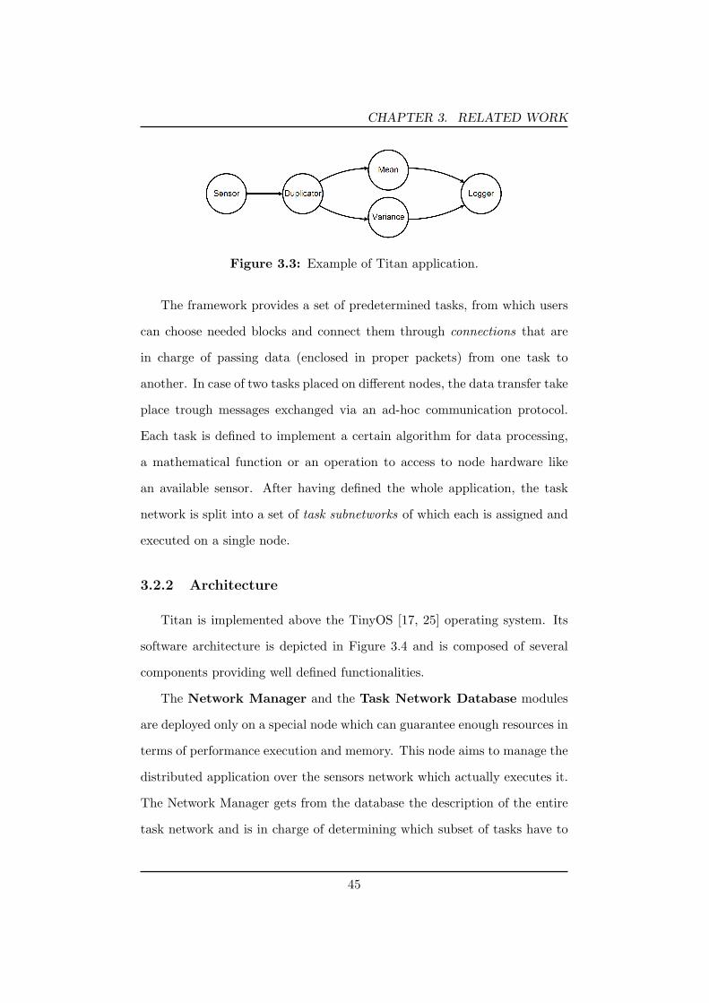
CHAPTER 3. RELATED WORK
Figure 3.3: Example of Titan application.
The framework provides a set of predetermined tasks, from which users
can choose needed blocks and connect them through connections that are
in charge of passing data (enclosed in proper packets) from one task to
another. In case of two tasks placed on different nodes, the data transfer take
place trough messages exchanged via an ad-hoc communication protocol.
Each task is defined to implement a certain algorithm for data processing,
a mathematical function or an operation to access to node hardware like
an available sensor. After having defined the whole application, the task
network is split into a set of task subnetworks of which each is assigned and
executed on a single node.
3.2.2 Architecture
Titan is implemented above the TinyOS [17, 25] operating system. Its
software architecture is depicted in Figure 3.4 and is composed of several
components providing well defined functionalities.
The Network Manager and the Task Network Database modules
are deployed only on a special node which can guarantee enough resources in
terms of performance execution and memory. This node aims to manage the
distributed application over the sensors network which actually executes it.
The Network Manager gets from the database the description of the entire
task network and is in charge of determining which subset of tasks have to
45
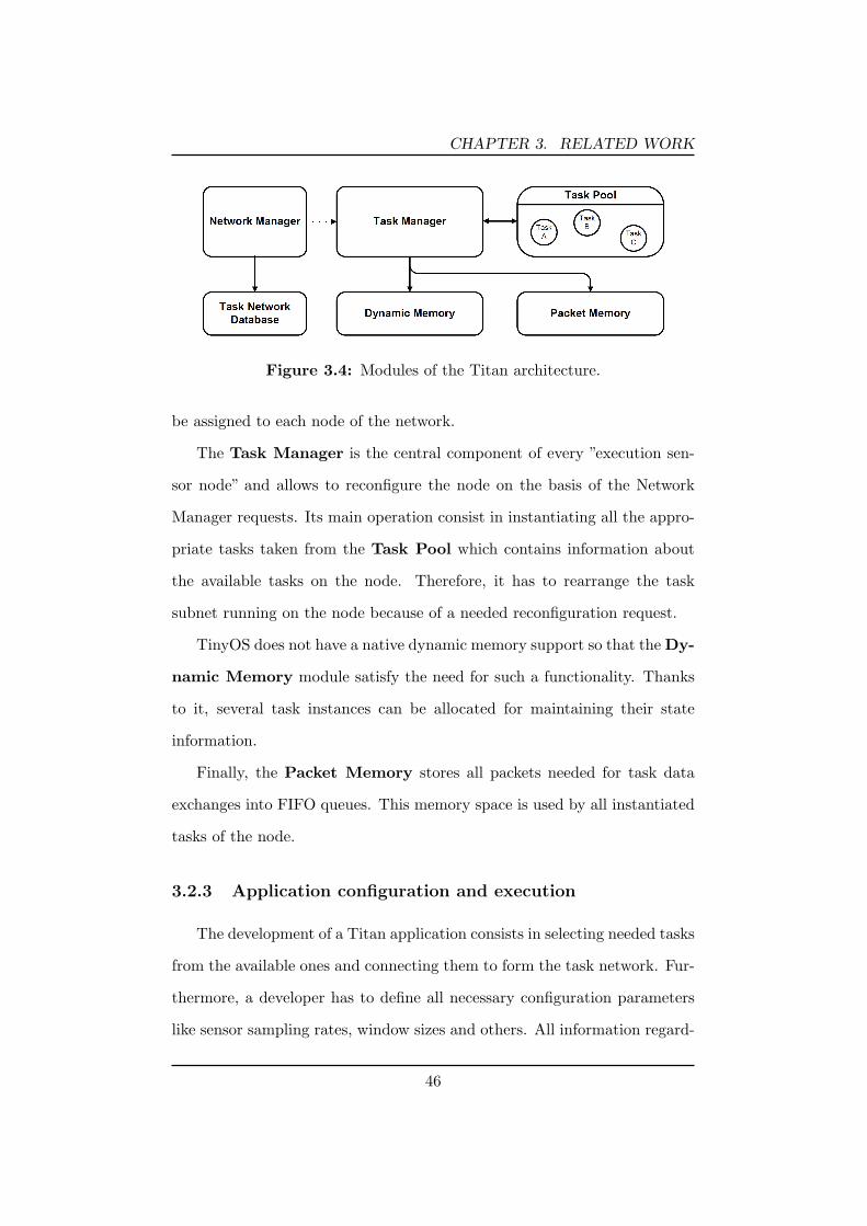
CHAPTER 3. RELATED WORK
Figure 3.4: Modules of the Titan architecture.
be assigned to each node of the network.
The Task Manager is the central component of every ”execution sen-
sor node” and allows to reconfigure the node on the basis of the Network
Manager requests. Its main operation consist in instantiating all the appro-
priate tasks taken from the Task Pool which contains information about
the available tasks on the node. Therefore, it has to rearrange the task
subnet running on the node because of a needed reconfiguration request.
TinyOS does not have a native dynamic memory support so that the Dy-
namic Memory module satisfy the need for such a functionality. Thanks
to it, several task instances can be allocated for maintaining their state
information.
Finally, the Packet Memory stores all packets needed for task data
exchanges into FIFO queues. This memory space is used by all instantiated
tasks of the node.
3.2.3 Application configuration and execution
The development of a Titan application consists in selecting needed tasks
from the available ones and connecting them to form the task network. Fur-
thermore, a developer has to define all necessary configuration parameters
like sensor sampling rates, window sizes and others. All information regard-
46

CHAPTER 3. RELATED WORK
ing task network and task configurations are loaded into the Task Network
Database.
If a specific application is requested to execute on a sensor network,
the following operations are performed. First of all, the Network Manager
discovers all actual capabilities of sensor nodes by sending a service discovery
message containing information about the necessary tasks composing the
application. Every node of the network replies with a list of available tasks
in its Task Pool.
From these information, the Network Manager can establish whether the
application can be executed and which task subnetwork is assigned to each
node.
In Figure 3.5 is shown how a task network is split into different parts
and each of them is allocated to different sensor nodes. The Task Manager
on each node is in charge of local instantiation and configuration of tasks
belonging to the subnetwork assigned to node by the Network Manager. If
storing task state information is necessary, the Task Manager can allocate
memory space from the Dynamic Memory module. To cope with tasks
communication placed on different nodes the Task Manager automatically
allocates a communication task during the application configuration phase.
It handles data exchange enclosing information into packets sent over the
wireless protocol. The authors recommend a maximum size for these packets
of 24 bytes, allowing to fit them into TinyOS active messages.
After having configured the task network over the WSN, the application
execution can start. Every time a task receives data in its input, from
another local or remote task, it is execute to process them on the basis of
the task configuration. Furthermore, it runs to completion before another
task can execute.
47

CHAPTER 3. RELATED WORK
Figure 3.5: Task subnetworks allocation of a Titan Application.
During the execution time, the Task Manager periodically checks if some
changes in the application configuration have to be carry out. In these
cases it recomputes and updates the task subnetworks, informing all Task
Managers of the nodes about the new situation.
The application execution ends when all tasks in every node have fin-
ished.
The authors evaluated [33] the Titan framework implementation on Tmote
Sky sensor platform [11], showing that for a typical activity recognition ap-
plication, the sensors (accelerometers) sampling rate of 100 Hz allow suffi-
cient execution time for the needed processing operations.
3.3 ATaG: Abstract Task Graph
The Abstract Task Graph (ATaG) [4, 43] represents a methodology and
a programming language for developing wireless sensor network applications
through an architecture-independent macroprogramming approach (see sec-
48

CHAPTER 3. RELATED WORK
tion 2.5.2). This means that developer have to specify a global behavior for
the application and the framework translates it into node-level specifications.
3.3.1 Application definition
An ATaG application is defined as a set of abstract tasks representing
computational operations and a set of abstract data items representing data
to be exchanged between abstract tasks. Every task has well-defined in-
put/output interfaces (channel) that declare which data item the task con-
sumes and which it produces. The ”abstract” adjective is to indicate that
the number and the placement of tasks are determined at compile-time de-
pending on the target network deployment.
The framework makes use of a data-driven control flow mechanism and
allow a hybrid imperative-declarative programming style for defining the
applications.
The first characteristic consists in abstract tasks behaving as passive
objects. They do not directly interact with each other but on the contrary
a task interacts with only data items, stored in a data pool, through its
input/output channels. Thus, a task is scheduled for execution only when
appropriate input data are available. For these reasons, the data-driven
paradigm allows programs reusability due to decoupled tasks.
On the other hand, the mixed imperative-declarative language allows to
separate definitions of when tasks fire and where tasks have to be deployed
on a sensor network from what each single task have to do on execution. The
former is provided by a declarative approach, discussed in the next section,
while the latter is provided by user imperative code that implements the
actual processing operation on input data.
49

CHAPTER 3. RELATED WORK
3.3.2 Programming syntax
The declarative part of an ATaG program consists of a set of abstract
elements, tasks, data items and channels which have to be defined with a
proper declarative language. Different from typical declarative programming
approaches like logic programming or functional programming (adopted by
another sensors macroprogramming framework, Regiment [37, 38]), ATaG
makes use of a graphical approach for defining its declarative programming
syntax.
One of the language constructs related to each abstract element is rep-
resented by a set of so called annotations which specify appropriate param-
eters. Each annotation is constituted of a couple, a type and the relative
value.
Every task has a unique label name defined by the programmer and a
set of annotations which indicate information about how many instances of
the task have to be instantiated on the network and when the task should
be executed by the framework runtime. But its actual behavior depends
on the associated executable code defined with a traditional programming
language which of course must be supported by the target sensor platforms
in the network.
A data item represents an object type and, similar to task, has a unique
defined label name and also an application specific payload which gener-
ally consists in a set of variables defined with a traditional programming
language.
A channel connects a task with an item data and represents which in-
stances of that data type the task is interested to.
An example of a complete ATaG application for environment monitoring
50

CHAPTER 3. RELATED WORK
is shown in Figure 3.6. The application is divided into two different parts
one for temperature and the other for pressure monitoring. It is assumed
that all sensor nodes have a temperature and a pressure sensor.
Figure 3.6: Environment monitoring application.
The abstract data items are indicated with rectangles: Temperature
and Pressure represent readings data from the sensors, while LocalAlarm,
GlobalAlarm and Maximum are object data derived from tasks computation.
The annotations, both for tasks and for channels, are represented as rounded
rectangles. All abstract tasks, depicted with an oval shape, are instantiated
in every nodes of the network due to the ”nodes-per-instances:1” annotation.
The Monitor task periodically samples the local temperature and send
the data to all the 1-hop distance nodes without storing it on the local data
pool. It also triggers if one of the neighbors communicates its own tem-
perature value (the ”any-data” annotation). If the temperature difference
between a node and its neighbors exceeds a threshold a LocalAlarm data
item is generated so that the task Corroborator fires and requests temper-
ature data from all nodes within a range of 10 meters (see the annotation
”10m:pull”). This task is in charge of checking if the generated alarm is false
due to a sensor malfunction. If the alarm is indeed valid a GlobalAlarm
data may be generated.
Concerning the second part of the application, the Sampler task period-
51

CHAPTER 3. RELATED WORK
ically store the pressure on the node, whereas the Aggregator is executed
whenever an instance of Pressure is locally produced (by the Sampler) or an
instance of Maximum is received from any of the node children of a virtual
tree, which is automatically built and maintained by the framework runtime.
The Aggregator result, that is the new computed Maximum item, is sent up
to its parent.
Apart from the annotations showed in the previous example, several
other ones are included into the ATaG declarative programming syntax.
Regarding tasks, annotations are classified into two types, ”Instantiation
annotations” and ”Firing annotations”. The first allow to explicit where
task instances have to be placed in the network, for example on a particular
node, on all nodes or by indicating a spatial density. In the last case, the
”nodes-per-instance:n” annotation states that one task instance is created
for each ”n” nodes of the network. Firing annotations, instead, allow to set
when a task is scheduled for execution: periodically (”periodic:p”), on all
input data availability (”all-data”) or when at least one input data item is
available (”any-data”).
Channel annotations are used to express relations among tasks and pro-
duced/consumed data items, for example if locally store a generated data
into the data pool (”local”), transmit it to all nodes (”all-nodes”) or selected
neighbors (”neighborhood-hops:n” and ”neighborhood-distance:d”) or nodes
of a virtual tree (”parent” and ”children”).
3.3.3 Application deployment
After having defined all the necessary application specifics through the
ATaG syntax discussed in section 2.2, a real node-level application have to
be created for the following deployment on the target sensors network.
52

CHAPTER 3. RELATED WORK
The processes involved in such a operation are depicted in Figure 3.7.
The framework compiler receives two inputs from the application developer,
the declarative part of the program and the description of the target net-
work. The latter consists in a file formatted in a particular form, the ANG
(Annotated Network Graph) which contains information such as the number
of nodes and the nodes connections.
A code generator provides code templates from the Abstract Task Graph
which has to be completed with the imperative code provided by the pro-
grammer to add actual tasks processing functionalities. The annotations of
the ATaG definitions together with the ANG are then interpreted to gener-
ate a configuration file for each node of the network, so that to customizes
all their behaviors based on their functions on the whole system.
Finally, the codes of sensors are synthesized and ready for the real de-
ployment on nodes.
Figure 3.7: ATaG application development.
A compilation framework developed for the ATaG system is deeply dis-
cussed in [41] whereas a graphical toolkit for an actual application devel-
53
CHAPTER 3. RELATED WORK
opment called Srijan is presented in [40]. To date, this tool is available for
SUN Spot sensors platform [51].
3.3.4 DART: the Data-driven ATaG Runtime
The node-level code synthesized by the ATaG compiler is appositely
generated to run on top of the ATaG runtime system (DART [39]) that in
turn runs on the sensor platform. Figure 3.8 shows the high level overview
of the structure of the system which is composed of several modules with
different functionalities. The TAaGManager is responsible for maintaining
all information about the declarative part of the ATaG program such as tasks
and channels annotations and tasks firing rules. The DataPool manages the
instances of the data items produced or consumed by tasks at the node.
The LogicalNeighborhoods (this component appears in [41] and it encloses
all functionalities of the NetworkArchitecture and the Dispatcher modules
that appear in an older DART architecture [39]) implements a dedicated
routing scheme for addressing neighbors within a certain hop-count. Finally
the NetworkStack handles the physical layer protocols for communicating
with other nodes over the network.
The DART runtime implementation models the semantic execution of
an ATaG application. Every task execution is atomic, in the sense that
an application-level task runs to completion before another one can start
executing.
Another important characteristic concerns the data items management.
Every tasks depending on a same data item consumes the same instance of
that data. This means that a particular instance that triggered the tasks will
not be overwritten or removed from the data pool before every scheduled
dependent task finishes execution. Thus, an eventual insertion of a new
54

CHAPTER 3. RELATED WORK
Figure 3.8: DART: Data-driven ATaG runtime system.
data instance is not guaranteed to succeed if not all tasks depending on the
older instance have terminated. It can happen if the data production rate is
greater than the data consumption rate. Finally, when all these dependent
tasks finish, the used data instance can be eliminated from the pool.
3.4 Considerations
Composing a distributed application from a set of elementary and de-
coupled functional blocks is the ideal method for allowing a rapid design and
implementation of wireless sensor networks application without the need for
any knowledge about the underlying operating system or hardware plat-
forms. Thanks to that every user is able to model its own application with-
out the need for being a programmer. This is a great opportunity for any
domain expert who wants to take advantages from using a WSN as a data
computing and who has only to know how analyzing a particular domain
phenomenon. With such an instrument he has only to focus on the high-
55

CHAPTER 3. RELATED WORK
level concepts concerning the signal processing operations and controlling
the work flow of the computing process from the sensor raw data to the final
computed results.
Among the previously discussed framework, Titan seems to be the one
which have more common characteristics with the proposed framework (see
Chapter 4). But its runtime architecture is not designed for allowing a rapid
porting towards platforms different from the TinyOS-based ones, because it
has been implemented so that it is deeply coupled to its features and ser-
vices. Furthermore, Titan does not have a proper data semantic relationship
between tasks, because differently from the proposed task, its programming
definition and execution is not supported by a well-defined high-level lan-
guage.
The ATaG middleware adopts an explicit approach for defining data
items used by the user applications. In the proposed framework, this is not
necessary because the presence of data is implicit into the definition of the
tasks and the user does not have to worry about them, but he can implic-
itly manage them through composing the work flow (connecting all needed
tasks). Moreover the proposed framework has been designed for make im-
mediately available the fundamental elements for building and executing a
signal processing without the need for using any kind of code whereas ATaG
system requires to code every defined tasks using the programming language
compatible with the target deployment platform.
56

Chapter 4Framework design and
implementation
The following chapter illustrates the characteristics and the functionali-
ties of the proposed framework, emphasizing on how it could be very useful
for developers and which instruments it provides for allowing users without
programming knowledges to design, deploy and execute an application on a
wireless sensor network.
In section 4.1 a general overview of the framework is provided, showing
the organization of the overall system. Details related to the constructs of
the high-level language used for specifying the behavior of the WSN applica-
tion are presented in Section 4.2. Section 4.3 and 4.4 describe the software
architectures design, the implementation and the functionalities of the two
main parts constituting the whole framework. The coordinator-side com-
ponent encloses the necessary libraries and instruments for managing the
sensor network and for configuring the user applications, whereas the node-
side component is in charge of the actual application execution through a
task runtime system running on top of operating system of every node in the
57

CHAPTER 4. FRAMEWORK DESIGN AND IMPLEMENTATION
network. Finally, details on the communication protocol between coordina-
tor and sensor nodes are provided in Section 4.5, whereas the application
development cycle is discussed in section 4.6.
4.1 Framework overview
The proposed framework has been conceived with the intention of mak-
ing WSN signal processing application development a simplified process re-
lieving users of the needs to be programming skilled person and to know
detailed information about the specific hardware architectures of the node
constituting the sensor network used for deploying their applications. This
comes from a simple and obvious consideration: since WSNs have becoming
more and more important in a wide range of application contexts it is very
likely that users intended to exploit sensors capabilities are not well disposed
to deal with a complex and time-consuming preliminary phase of studying
new hw/sw platforms. On the contrary, they would desire a powerful instru-
ment able to allow a simple but effective software prototyping and a quick
deployment of applications over a network.
In consideration of the above requirements, the first fundamental ques-
tion to cope with is that of deciding what particular application development
approach the framework has to support. Chapter 2 and 3 have shown dif-
ferent design methodologies and middlewares for assisting sensors program-
ming. On the basis of a study of their diverse characteristics and distinc-
tive features and taking into account their pros and cons in using them in
different application domains, it has been decided that the task-oriented
paradigm can be the ideal technique for allowing users to model their own
applications.It provides a way to conceive a graphical high-level behavior of
the application, like the one shown in Figure 4.1. In this particular example,
58

CHAPTER 4. FRAMEWORK DESIGN AND IMPLEMENTATION
the max, mean and min values of a series of temperature data coming from
a sensor are evaluated and the results are transmitted to another node or to
the coordinator.
As a consequence to the simple definition, this choice implies the design
and the implementation of an appropriate runtime system for interpreting
and executing these applications specifications.
Sensing(Temperature) TransmissionMean
Min
Max
Split Aggr
Figure 4.1: Example of a task-oriented application.
The task-oriented paradigm adopted by the framework comes along with
an high-level language, which exposes a set of constructs expressly defined
for supporting such a approach. These constructs represent the elementary
concepts through which users specify the behavior of the applications. This
modeling language is shown to be simple, yet expressive enough for becoming
the preferred method used for describing a typical distributed application
aimed to data and signal processing. Moreover, its intrinsic nature allows the
required reusability and reconfigurability of the application to be satisfied.
The details and the benefits in using the task-oriented paradigm are shown
in section 4.1.1 whereas, the description of the supported definition language
is reported in section 4.2.
The main motivation that has led to a task-oriented architecture is that
most of the current middlewares provide high-level services for data col-
lection and querying but they do not allow to define an explicit data flow
59

CHAPTER 4. FRAMEWORK DESIGN AND IMPLEMENTATION
processing which is very useful in many application domains, such as con-
text recognition, health monitoring and medical assistance. Furthermore,
differently from many others middleware, this new framework is conceived
to support an application definition method that avoid users the need for
writing any programming code.
In fact, with respect to this methodology an application can be simply
specified as a set of tasks connected together. Each task represents a par-
ticular activity, such as a sensing operation, a processing function or a radio
data transmission. The user has only to select a certain number of tasks
from a set of available ones on the basis of the application requirements.
Afterwards, he has to join together pairs of tasks with a connection if nec-
essary, so that the output result of the one correspond to the data input
of the other. In this way, the set of connected tasks form a direct graph
which defines the work flows performing a series of operations on the sensor
data and so represents the high-level description of the whole application.
Typically, a data processing application supported by the framework (see
Figure 4.1) consists in (1) accomplishing the needed sensor readings, (2)
passing the sensed data to processing functions which carry out some signal
processing operation and (3) sending result to other nodes of the network
(eventually for further data elaboration).
It is worth noting that, as the framework supports a distributed data
processing, users can decide where every task forming the application is
allocated over the sensor network.This is shown in Figure 4.2. So, each single
task is performed on a particular node, guaranteeing that the execution
of the application is maintained well balanced. In fact, depending on the
different features of the nodes constituting the network, the user can allocate
the tasks requiring more resources to node providing more computational
60

CHAPTER 4. FRAMEWORK DESIGN AND IMPLEMENTATION
capabilities.
Sensing(Temperature)
TransmissionMean
Intensive-computing
task
Split
AggrNODE 1
NODE 2(more processingcapabilities)
NODE 3
Figure 4.2: Application example having tasks instantiated on differentnodes.
For what concern the software architecture, the framework is composed
of two components, one is implemented on the coordinator of the WSN, the
other is implemented on the sensor nodes. The former is a Java application
running on a laptop or an handheld device through which the user configures
and manages the sensor network and the task-application to be deployed on
it. The latter represents the middleware engine running on top of the sensor
node operating system. It is responsible of handling the messages coming
from the coordinator which are used, among the other things, for configuring
the portion of the user application assigned to the node. It is also in charge
of managing and executing the tasks that are instantiated on the node.
Currently, the node-side part of the framework has been implemented and
tested on the TelosB sensor platform [56] running the TinyOS operating
system [10, 17, 25]. But, as will be discussed later, the framework has been
61

CHAPTER 4. FRAMEWORK DESIGN AND IMPLEMENTATION
designed so that it allows a fast porting to others C-like software architecture.
4.1.1 The task-oriented approach
The way of modeling a sensor network application through a task-oriented
methodology aims at providing an abstract description of the real applica-
tion running on the nodes by omitting low-level details and thus reducing
complexity which is usually inherent in such a distributed software.
The basic blocks contained in this formalism are tasks and task-connections.
A task represents a well defined node activity which can consist for example,
in a processing operation rather than a data transmission or a sensor read-
ing. Usually they are defined as a unit of ”work” that can not be subdivided
(i.e. it is atomic). But the atomicity of a task is only with respect to oth-
ers tasks, and this behavior is quite obvious in relation to the fact that the
event-reactive nature of the sensor nodes imply the need for a fast response
to asynchronous events (a radio message reception or a timer expiration to be
handled). A task-connection represents a relationship between tasks which
generally consists in having some kind of dependency, such as temporal and
data dependency. Furthermore, these tasks relationships are semantically
consistent thanks to the well-defined input and output interfaces.
Such a system representation, which capture both data and control flow,
allows for a better application definition that in turn will lead to effective
scheduling activities and in general to a more efficient system implementa-
tions. Designing an application as a composition of elementary blocks with
fixed interfaces enables a rapid application reconfiguration by the user and
then a more simple application maintenance. Moreover, a system adopting
a task-oriented approach can easily be enhanced in functionality, by simply
adding new task definitions which represent further computing capabilities.
62

CHAPTER 4. FRAMEWORK DESIGN AND IMPLEMENTATION
Most important, adding these new blocks will not imply the need of changing
definition of all others one neither it needs the underlaying task management
software to be modified. This is achieved thanks to the fact that every task
is decoupled with each other and the only relation point is through their
input/output interfaces namely the data they need/provide.
4.1.2 Main characteristics
The proposed development system has been designed taking into account
the motivations that have led to the conception of many of the current
middlewares reported in literature. From this considerations, it has been
ensured most of the desired characteristics that the framework would have
had for assuring the best result to users who want an instrument allowing a
fast and effective application definition and execution over a WSN.
In the following, the main aspects characterizing the framework are de-
scribed.
Platform independence and quick portability : these are two very im-
portant factors to consider because the success and the wide diffusion
of a middleware depend on how many platforms it can support. And
this is particularly true for sensor networks, considering that at the
present low-cost mass production has permitted the development of a
wide variety of sensors platforms, and also it is not unusual that a sin-
gle application may be deployed on a WSN including different sensor
architectures (heterogeneous sensor network). So, one of the require-
ment for an application development tool is that of being predisposed,
since its design phase, for a rapid and simple portability process to-
wards different sensor architectures (considering both hardware and
software).
63
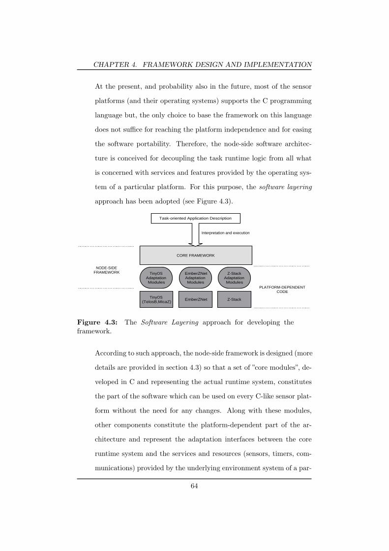
CHAPTER 4. FRAMEWORK DESIGN AND IMPLEMENTATION
At the present, and probability also in the future, most of the sensor
platforms (and their operating systems) supports the C programming
language but, the only choice to base the framework on this language
does not suffice for reaching the platform independence and for easing
the software portability. Therefore, the node-side software architec-
ture is conceived for decoupling the task runtime logic from all what
is concerned with services and features provided by the operating sys-
tem of a particular platform. For this purpose, the software layering
approach has been adopted (see Figure 4.3).
TinyOSAdaptationModules
CORE FRAMEWORK
Task-oriented Application Description
TinyOS(TelosB,MicaZ) EmberZNet Z-Stack
EmberZNetAdaptationModules
Z-StackAdaptationModules
Interpretation and execution
PLATFORM-DEPENDENTCODE
NODE-SIDEFRAMEWORK
Figure 4.3: The Software Layering approach for developing theframework.
According to such approach, the node-side framework is designed (more
details are provided in section 4.3) so that a set of ”core modules”, de-
veloped in C and representing the actual runtime system, constitutes
the part of the software which can be used on every C-like sensor plat-
form without the need for any changes. Along with these modules,
other components constitute the platform-dependent part of the ar-
chitecture and represent the adaptation interfaces between the core
runtime system and the services and resources (sensors, timers, com-
munications) provided by the underlying environment system of a par-
64

CHAPTER 4. FRAMEWORK DESIGN AND IMPLEMENTATION
ticular target sensor platform (such as TinyOS [10], EmberZNet [13],
Z-Stack [27]). In order to make a porting of the framework to a new
sensor platform, the latter software components are the only software
that a developer has to provide.
Extensibility : a middleware should provide a way for allowing developers
to easily improve it with possible enhancements because a constraint
in this sense may limit its use in the future. The chosen task-oriented
design methodology is a perfect example of how is possible a straight-
forward approach for adding new functionalities beside to the existing
ones. This is done by simply defining new tasks which represent fur-
ther computing capabilities and developers do not have to change the
underlying runtime logic or the other task definitions, thanks to the
fact that the runtime does not care about what tasks do whereas ev-
ery task is decoupled with each other. The framework allows also a
fast way for supporting new hardware resource such as sensor types or
actuators.
Modularity : concerning the design of complex software systems, it is
always useful to conceive an architecture composed by several mod-
ules, each of them devoted to a particular purpose and interacting
each others through well-defined interfaces. The approach of defining
a modular entity constituted by different and independent functional
blocks allows a more rapid implementation time and a more effective
software maintenance and improvement of functionalities. For exam-
ple, it may be possible that future requirements need a different way
for managing the memory or the tasks execution. Thanks to the mod-
ularity, the modifications made by the framework developers affects
65

CHAPTER 4. FRAMEWORK DESIGN AND IMPLEMENTATION
only the correspondent modules without the risk of causing damages
to the rest of the architecture.
Flexibility for the final user : the success of a development tool depends
not only on the easiness in using it but also on the flexibility that the
tool provides to the final user (i.e. the WSN application developer)
by avoiding, as much as possible, the constraints to impose during the
application design. In the particular case of the proposed framework,
a user can define how many tasks he needs, setting values for their
parameters with a wide freedom of choice and maintaining an high
abstraction on the real capabilities of the node. Of course, the only
limitations are dictated by the actual amount of resources on the node.
4.1.3 Network topology
The network architecture supported by the framework is composed by a
coordinator node (or base station) and a set of sensor nodes. Its topology
is depicted in Figure 4.4. It is worth noting that it is more than a simple
”pure” star-configuration (blacks links), since an inter-node communication
capability (red links) is expected for allowing the interaction between tasks
instantiated on different sensor nodes. In principle it is possible for a node
to communicate with all the others inside its radio range but, actually, the
communication between two nodes is established only if they have instanti-
ated tasks that have to exchange data.
It has been already talked that the coordinator is in charge of defin-
ing and configure the user application whereas the sensor nodes handle the
actual execution of the distributed tasks. Through the former, the user
specifies which tasks to include into the application, their configuration pa-
rameters, how they are connected together and on which node every single
66
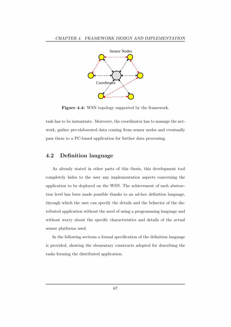
CHAPTER 4. FRAMEWORK DESIGN AND IMPLEMENTATION
Coordinator
Sensor Nodes
Figure 4.4: WSN topology supported by the framework.
task has to be instantiate. Moreover, the coordinator has to manage the net-
work, gather pre-elaborated data coming from sensor nodes and eventually
pass them to a PC-based application for further data processing.
4.2 Definition language
As already stated in other parts of this thesis, this development tool
completely hides to the user any implementation aspects concerning the
application to be deployed on the WSN. The achievement of such abstrac-
tion level has been made possible thanks to an ad-hoc definition language,
through which the user can specify the details and the behavior of the dis-
tributed application without the need of using a programming language and
without worry about the specific characteristics and details of the actual
sensor platforms used.
In the following sections a formal specification of the definition language
is provided, showing the elementary constructs adopted for describing the
tasks forming the distributed application.
67

CHAPTER 4. FRAMEWORK DESIGN AND IMPLEMENTATION
4.2.1 Tasks
The various typologies of task represent the fundamental elements of
the language. They can be subdivided into two main categories: data-
processing tasks and data-routing tasks. The former tasks perform
functions related to data processing and execution control, whereas the latter
ones provide store-and-forward and data replication functionalities.
Every task is coupled with a description (namely ”task description”)
which include the following attributes as shown in Figure 4.5 and Figure 4.6:
INPUT, OUTPUT, and PARAMETERS.
TaskTypetaskname
taskname{ INPUT: in | < > | no_input; OUTPUT: out | < > | no_output; PARAMS: (par=val)*;}
Figure 4.5: Data-Processing Task Description.
TaskTypetaskname
taskname{ INPUT: in+; OUTPUT: out+; PARAMS: (par=val)*;}
Figure 4.6: Data-Routing Task Description.
In particular, the input and output attributes can have one of the fol-
lowing values:
- ”in” or ”out” : represent generic input and output. The user does
not have to care about how data are formatted, and the actual data
structure depends on the middleware that implements the language
specifications.
68

CHAPTER 4. FRAMEWORK DESIGN AND IMPLEMENTATION
- ”< >” : indicate an empty input/output, that is it exists but it does
not contain any useful information. It is similar to a notification that
a task is completed.
- ”no input” or ”no output” : declare the absence of input/output. At
the moment, no tasks without both input and output are defined.
The pair (par=val) represents the setting of a task parameter, and on the
basis of the particular task (denoted by TaskType) there could be 0 or more
parameters. Finally the symbol ”+” in the description of the data-routing
tasks indicates the presence of multiple input/output connections.
In the following, the hierarchy of the different types of task defined so
far are shown, along with their purposes.
• TimedTask , is the super-category that includes every temporized
task:
TimingTask : allows to define timers for timing other tasks.
SeningTask : defines sensing operations on a sensor node and in-
clude a timer for setting the sampling time.
• FunctionalTask , includes tasks for data manipulation:
ProcessingTask : performs data processing functions and algorithms,
allowing to specify the type of operation to accomplish; particular op-
erations are the so called ”feature extractions” which are mathematical
function applied to a data series, such as Mean, Variance, etc.
TransmissionTask : allows an explicit transmission of data gener-
ated by other tasks, sending them to a specific addressee node. Gen-
erally it is used for sending data and information to the coordinator
69

CHAPTER 4. FRAMEWORK DESIGN AND IMPLEMENTATION
whereas, implicit data transmissions take place in the case of connected
tasks located into different nodes.
• FlashingTask , this category allows to use the on-board flash memory:
StoringTask : stores data coming from its input on the flash mem-
ory.
LoadingTask : retrieves data from the flash for being used by other
tasks of the application.
• DataRoutingTask , comprises:
SplitTask : duplicates data of its input to every output links for
making them available to other tasks.
AggregationTask : collects data coming from its multiple inputs
carrying them to output.
HistoricalAggregationTask : similar to the previous task but sup-
porting a series of aggregation operations over the time, before bring
them to output.
After having shown a brief overview of the tasks included so far into the
definition language, in the following more detailed information about each
of them is given.
Figure 4.7 depicts the description of the TimingTask . It does not have
to elaborate any input data so it has no input link. Its function is only
to signal in output a notification when its inner timer is expired. For this
reason, the output attribute has the ”empty” value. The user configures the
70

CHAPTER 4. FRAMEWORK DESIGN AND IMPLEMENTATION
task by setting the timer parameter, such as the periodicity, the period to
expiration and the corresponding time scale.
Timingtaskname
TimingTask{ INPUT: no_input; OUTPUT: < >; PARAMS: isPeriodic= true | false, period= t, timeScale= mills | sec | min | h;}
Figure 4.7: TimingTask Description.
The SensingTask (see Figure 4.8) represents a sensing reading from
a particular on-board sensor. Obviously, it has no input, whereas the pro-
vided output depends on the specific type of sensor device specified as a
parameter. Like the TimingTask, its configuration includes settings for the
inner timer necessary for timing the sensing operation. A SensingTask can
be associated to several different types of physical devices, many of which
providing more than a single sensed value. For these reason, the output of
a sensor can be seen as a series of ”channels” each of which is devoted to
one of a multiple reading related to a unique sensing operation. The chan-
nelSelection parameter let the user to choice which of the available channels
values should be provided to the output.
To be more clear, just consider as an example a tri-axial accelerometer.
On every sensing operation, usually it provides three different values, each
corresponding to a particular axis (AccX, AccY, AccZ) and then associated
to three different channels. Through the ”channelSelection” parameter, the
user may decide which of the available sensed values have to be provided to
output by the task. This parameter can be simply associated to a boolean
array.
71
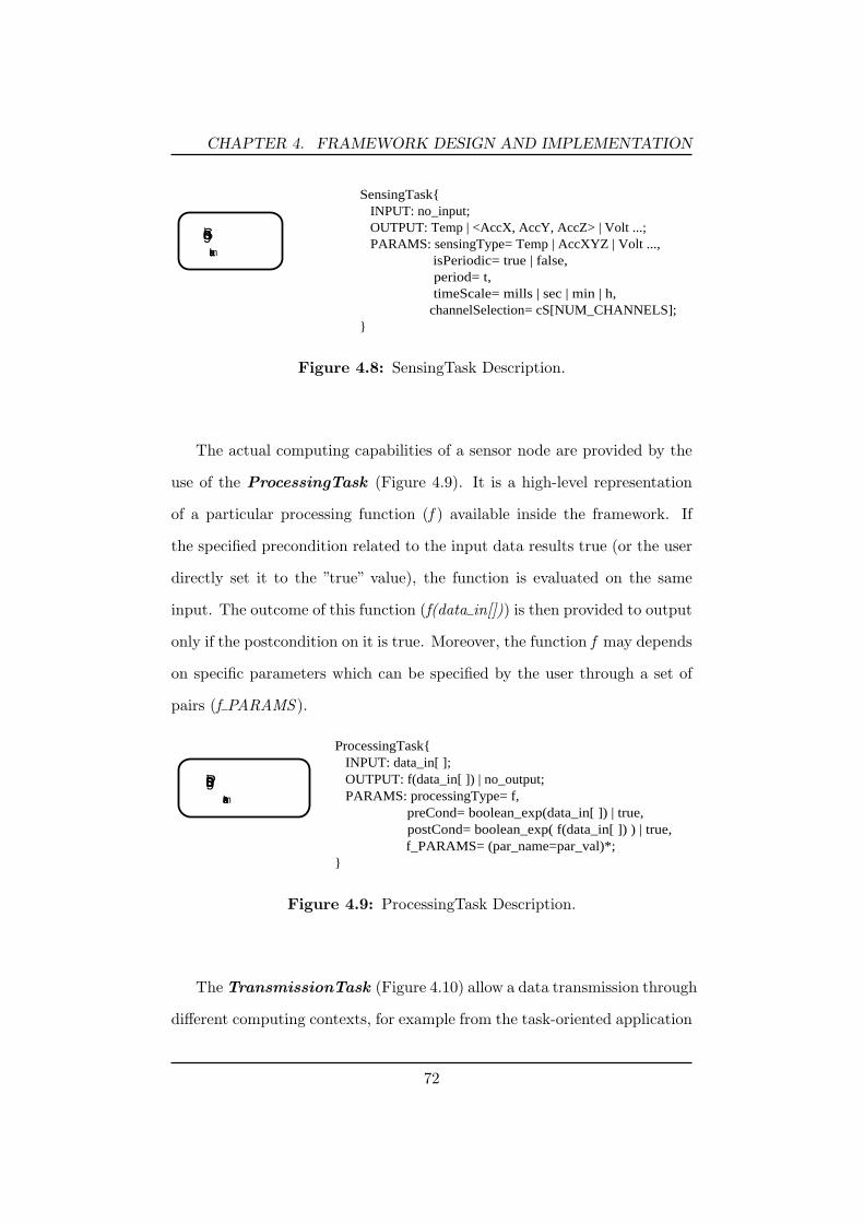
CHAPTER 4. FRAMEWORK DESIGN AND IMPLEMENTATION
Sensingtaskname
SensingTask{ INPUT: no_input; OUTPUT: Temp | <AccX, AccY, AccZ> | Volt ...; PARAMS: sensingType= Temp | AccXYZ | Volt ..., isPeriodic= true | false, period= t, timeScale= mills | sec | min | h, channelSelection= cS[NUM_CHANNELS];}
Figure 4.8: SensingTask Description.
The actual computing capabilities of a sensor node are provided by the
use of the ProcessingTask (Figure 4.9). It is a high-level representation
of a particular processing function (f ) available inside the framework. If
the specified precondition related to the input data results true (or the user
directly set it to the ”true” value), the function is evaluated on the same
input. The outcome of this function (f(data in[])) is then provided to output
only if the postcondition on it is true. Moreover, the function f may depends
on specific parameters which can be specified by the user through a set of
pairs (f PARAMS ).
Processingtaskname
ProcessingTask{ INPUT: data_in[ ]; OUTPUT: f(data_in[ ]) | no_output; PARAMS: processingType= f, preCond= boolean_exp(data_in[ ]) | true, postCond= boolean_exp( f(data_in[ ]) ) | true, f_PARAMS= (par_name=par_val)*;}
Figure 4.9: ProcessingTask Description.
The TransmissionTask (Figure 4.10) allow a data transmission through
different computing contexts, for example from the task-oriented application
72

CHAPTER 4. FRAMEWORK DESIGN AND IMPLEMENTATION
to a gateway (like the base station). The user must set an address or some
kind of node identifier, representing the addressee of the data.
Transmissiontaskname
TransmissionTask{ INPUT: data_in; OUTPUT: data_in; PARAMS: destination= destinationLabel;}
Figure 4.10: TransmissionTask Description.
The capability to hold persistent data on a node is provided by the
StoringTask (Figure 4.11) which simply takes its input data and store
them into the flash memory placed on-board of the sensor node. The unique
mem location parameter represent a symbolic location of the memory.
Storingtaskname
StoringTask{ INPUT: data_in; OUTPUT: no_output; PARAMS: mem_location= @label;}
Figure 4.11: StoringTask Description.
The LoadingTask (Figure 4.12) is generally used to retrieve data pre-
viously saved by the StoringTask. The user should provide the same value
for the mem location parameter.
Loadingtaskname
LoadingTask{ INPUT: < >; OUTPUT: raw_data; PARAMS: mem_location= @label;}
Figure 4.12: LoadingTask Description.
73

CHAPTER 4. FRAMEWORK DESIGN AND IMPLEMENTATION
The SplitTask shown in Figure 4.13 is one of the data-routing tasks.
It is in charge of carrying the data coming from its input to the n outputs,
so that it makes available the same data to a set of other tasks. However,
each output link may only include a subset of the input data, depending on
the boolean matrix dataSelection[i][j], which declare if the i-th output has
to contain the j-th input data entry.
Splittaskname
SplitTask{ INPUT: data_in [DATA_IN_LENGTH]; OUTPUT [1]: selectionOn(data_in[ ], selOut[1]), OUTPUT [2]: selectionOn(data_in[ ], selOut[2]), ... OUTPUT [n]: selectionOn(data_in[ ], selOut[n]); PARAMS: outCount= n, selOut[1]= dataSelection [1][DATA_IN_LENGTH], selOut[2]= dataSelection [2][DATA_IN_LENGTH], ... selOut[n]= dataSelection [n][DATA_IN_LENGTH];}
Figure 4.13: SplitTask Description.
The AggregationTask (Figure 4.14) allows to collect all data coming
from its n inputs, making them available for the unique output.
Aggrtaskname
AggregationTask{ INPUT [1]: data_in [1], INPUT [2]: data_in [2], ... INPUT [n]: data_in [n]; OUTPUT: data_in [1] Å data_in [2] Å ... Å data_in [n] = < data_in [1], data_in [2], ... , data_in [n] >; PARAMS: inCount= n;}
Figure 4.14: AggregationTask Description.
The HistoricalAggregationTask (Figure 4.15) has a similar purpose
to the AggragationTask, but in addition it has the capability to perform
74

CHAPTER 4. FRAMEWORK DESIGN AND IMPLEMENTATION
m aggregation operation over the time and to maintain all collected data
before making them available to the output.
HAggrtaskname
HistoricalAggregationTask{ INPUT [1]: data_in [1], INPUT [2]: data_in [2], ... INPUT [n]: data_in [n]; OUTPUT: (data_in [1] Å data_in [2] Å ... Å data_in [n])[m] = < data_in [1], data_in [2], ... , data_in [n] >[m]; PARAMS: inCount= n, numAggregations= m;}
Figure 4.15: HistoricalAggregationTask Description.
4.2.2 Connections
Together with tasks, connections represent the base components of the
specification language. They are used by the developer to compose the task
graph application, because it does not only contain the set of needed tasks
to perform but also must have information about how the data pass from
a task to another one. So, the connections specify somehow the order of
execution of the tasks by constructing a kind of data flow processing net
(i.e. the distributed application running over a WSN).
Figure 4.16 depicts the definition of connection.
TaskType1task1
TaskType2task2
task1-->task2{ SOURCE_TASK: task1; DESTINATION_TASK: task2; task2.INPUT: task1.OUTPUT;}
Figure 4.16: Connection Description.
Because it is not possible for the tasks to be connected each other in an
arbitrary way, the Table 4.1 contains the list of the allowed connection.
75

CHAPTER 4. FRAMEWORK DESIGN AND IMPLEMENTATION
Table 4.1: List of allowed connection.
Source TaskType Destination TaskType
SensingTask FunctionalTask, StoringTask, DataRoutingTaskProcessingTask FunctionalTask, StoringTask, DataRoutingTaskTrasmissionTask -StoringTask -Loadingtask FunctionalTask, DataRoutingTaskDataRoutingTask FunctionalTask, Storingtask, DataRoutingtask
4.3 Node-side architecture
After having discussed the details concerning the definition language
used for describing the behavior of the user WSN application, this section
goes inside the architecture of the node-side middleware. This latter repre-
sents the runtime system needed to ”interpret” and ”execute” the high-level
intentions of the developer specified by the language constructs.
A preliminary design phase has led to the creation of a node software
middleware layer having the characteristics reported in section 4.1.2 and
whose architectural scheme is reported in Figure 4.17. As it can be noted,
this architecture is well-structured, and following a modularity approach it
comes with a set of independent but interacting modules, each of which has
been intended to fulfill a well defined purpose.
The components without a color correspond to the core framework of
the system. They are implemented in the C language, so that they can be
easily ported to practically every ”C-like” compatible sensor platforms, with-
out the need for changing their code. However, the very high portability of
the framework is not only enabled by the use of such a language, but mainly
by supporting a strong software decoupling between the runtime execution
logic (it encloses the unchangeable middleware layer logic including task
76

CHAPTER 4. FRAMEWORK DESIGN AND IMPLEMENTATION
ACTUATING-MODULE
TASKs-MODULE
FLASH-MODULE
COMM-MODULE
SENSING-MODULE
MEMORY-MODULE
ApplicationManager
RadioController
CommunicationManager
RadioAdapter
SensorManagerSensor_n
Sensor_1
TaskScheduler
TaskGraphManager
MemoryManagerBuffersManagerFlashController
FlashManager
TIMERs-MODULETimerManager
ActuatorManager
Actuator_1
Actuator_n
.
.
.
.
.
.
Timing
AggrSplit
Loading
Sensing
StoringTrasmissionProcessing
HAggr
Figure 4.17: Software architecture of the node-side part of the framework.
and memory management, application-level message communication han-
dling, abstract accessing to on-board sensors) and the components needed
for accessing the services and the features provided by the actual particular
platform on which the middleware is running. Then, the gray colored blocks
represent the architeture-dependent part of the framework, that is software
used to manage the specific resources on the node and that can not be
reused on platforms having a different hw/sw technology. In practice, they
are adaptation components (or drivers) which have the function of bridging
the core with the specific development environment, guaranteeing the access
to resources through well-defined interfaces.
The whole software system is coordinated by a central component, the
ApplicationManager. In the following, a brief summary of the various mod-
77

CHAPTER 4. FRAMEWORK DESIGN AND IMPLEMENTATION
ules is provided.
- Sensing-Module : allows the management of the various sensing de-
vices placed on the node, providing standard interfaces for accessing
them.
- Actuating-Module : similarly to the Sensing-Module, it allows the
use of the potential actuators installed on the sensor nodes, so that
not only it is possible to sense from the environment but also to interact
with it.
- Flash-Module : most of the microcontrollers comes with a flash mem-
ory to permanently store information into it. This module provide the
software logic required to access the such a memory, through a simple
interface for data storing and loading.
- Comm-Module : handles the application-level communication pro-
tocol, providing a service for sending/receiving messages to/from the
others sensor nodes or the coordinator. In particular it is in charge
of encapsulating these high-level messages information into specific
packets. It also provides fragmentation-defragmentation operations,
depending on the message length and on the max payload supported
by the transceiver low-level communication protocol.
- Timers-Module : contains the driver for managing the allocation of
timers through a service based on the publish/subscribe paradigm.
- Memory-Module : is responsible for the memory management. In
particular, this module provides other components an interface to sat-
isfy requests for a dynamic allocation of memory blocks.
78
CHAPTER 4. FRAMEWORK DESIGN AND IMPLEMENTATION
- Tasks-Module : it represents the ”execution engine”of the task-application
defined by the user.
4.3.1 Sensing Module
The main component of the module is the SensorManager which exposes
a series of functions for a simple management of a wide variety of physical
sensors. It is obvious that, for accessing many different sensor devices in a
transparent way (without knowledge on the actual details), it is needed the
availability of a specific driver for each sensor type to be supported by the
framework. Such drivers have to be properly designed for a correct use, that
is they have to expose a well known interface, so that the SensorManager
can consistently access them. In practice, they have to declare a specific and
predetermined set of functions.
In Listing 4.1 the declaration examples of two sensor driver interfaces are
shown. The first is related to the internal temperature sensor of the TelosB
platform [56], whereas the second is related to the tri-axial accelerator placed
on a sensor board expressly developed for the SPINE project [44]. The actual
implementation of this functions are made into the two respective driver
source codes developed with respect to the appropriate device specifications.
Just for clearness, the ifdef directive is used during compilation time to select
which sensor definitions have to be loaded along with the node-side part of
the framework.
As it can be seen in the code listing, the drivers should export four
functions: one for performing the actual sensing acquisition operation and
the others for returning the ID of the specific sensor, the type of acquisition
(synchronous or asynchronous) and the returned data dimensions. This
79

CHAPTER 4. FRAMEWORK DESIGN AND IMPLEMENTATION
Listing 4.1: Examples of sensor driver interfaces#ifdef PLATFORM TELOSB// HilInternalTemperatureSensorP.ncunsigned int TelosB InternalTemperature getID();unsigned char TelosB InternalTemperature getAcquisitionType();unsigned char TelosB InternalTemperature getDataDimensions();bool TelosB InternalTemperature acquire(unsigned char caller code,
enum SensorDataSelection dataSelection);#endif
#ifdef SPINE SENSOR BOARD// HilAccSensorP.ncunsigned int SPINESensorBoard Accelerometer getID();unsigned char SPINESensorBoard Accelerometer getAcquisitionType();unsigned char SPINESensorBoard Accelerometer getDataDimensions();void SPINESensorBoard Accelerometer acquire(unsigned char caller code,
enum SensorDataSelection dataSelection);#endif
latter information is very important, because the framework have to know if
the sensor returns more than one value every sensing reading. Furthermore,
the dataSelection parameter in the acquisition function is used to specify
which portion of the multiple data the sensor has to provide (it is directly
related to the channelSelection parameter of the SensingTask defined in
section 4.2).
The caller code parameter represent the unique identifier of the entity
requiring a sensor acquisition. It is a needed information for a correct man-
agement of the asynchronous sensors. In fact, suppose that two entity, A
and B, have to use a same sensor and that they request a sensor acquisition
in succession. It may be possible that the second acquisition (requested by
B) overwrite the first one, before that A retrieves the corresponding value
data. In order to avoid this, it is asked to every sensor driver to maintain a
list of values each of which relatives to a different entity.
80

CHAPTER 4. FRAMEWORK DESIGN AND IMPLEMENTATION
Because the SensorManager has been conceived to manage all supported
sensors in an asynchronous way, every sensing operation consists of two
phases:
1. the SensorManager request a new sensing acquisition on a specific
sensor;
2. after the physical sensor device has terminated the acquisition process,
the corresponding driver makes a callback to the manager for informing
it that the sensed data (single or multiple values) are available;
In the case of a synchronous sensor, its driver developer has to assure
that the callback function is called at the end of the acquisition function of
the driver.
4.3.2 Communication Module
Similarly to the SensingModule, the CommunicationModule has to rely
on a platform-dependent component for assuring a correct communication
management. In this case, the sensor node specific component is the radio
transceiver system and the relative low-level communication protocol (the
RadioController block of Figure 4.17). The RadioAdapter is an interfacing
component (see Listing 4.2) which has the function of bridging the Radio-
Controller with the CommunicationManager. The main services provided
by the RadioAdapter are retrieving the low-level address of the node in the
network, getting the maximum payload length supported by the specific
radio system protocol, and sending data to the specified address.
By using such an interface, the CommManager is able to communicate
with the other nodes and the coordinator. In particular, a higher protocol
layer above the one provided by the on-board radio has been developed. It is
81

CHAPTER 4. FRAMEWORK DESIGN AND IMPLEMENTATION
Listing 4.2: RadioAdapter interfaceunsigned int RadioAdapter getMaxPlatformPayloadLen();unsigned int RadioAdapter getNodeAddr();void RadioAdapter send(unsigned int destination, void∗ payload,
unsigned char len);
a point-to-point protocol with no support for data routing, but supporting
the fragmentation of long data messages so that the low level payload length
is not a limitation.
The communication protocol has its own packet format, containing all
information needed by the CommManager. In Figure 4.18 the structure of
the packet header is depicted, along with the dimension of each field.
4 4 8 16 16 8 8 8Version Future Use GroupID SourceAddr DestAddr SequenceNr Tot
Fragments FragmentNr
Figure 4.18: The packet header adopted by the framework.
Most of the fields has a explicit meaning. The only one to be explicitly
mentioned is the GroupID which is used for allowing a single coordinator to
independently manage different group of nodes, as the network is subdivided
into several logical set of sensors.
The CommManager does not care about the content of the packet pay-
load (containing application-level messages), which is managed by the Ap-
plicationManager.
4.3.3 Timers Module
Timers are essential resources for a sensor node, mainly because most of
the sensing operations are generally performed as periodic tasks. Because
of their strong dependency from the particular hardware architecture, no
platform-independent component is needed, but the availability of the only
82

CHAPTER 4. FRAMEWORK DESIGN AND IMPLEMENTATION
driver suffice for a good timer accessing management. Of course, every
timer driver has to be conceived with a well-defined interface so that core
framework components can access them consistently.
In Listing 4.3 the standard timer driver interface is listed. The services
offered by such a driver is conformed to the publish/subscribe paradigm. Any
components that need a timer (the subscriber) makes a request to the driver
passing to it its own identifier. If a timer resource is available, the driver
informs the component about the identification code of the timer that has
been assigned to it. This code allows a same component to allocate several
timers.
Listing 4.3: The timer driver interfacebool TimerManager allocateTimer(enum SubscriberType subType,
unsigned char ∗timerCode);bool TimerManager releaseTimer(enum SubscriberType subType,
unsigned char timerCode);bool TimerManager startTimer(enum SubscriberType subType,
unsigned char timerCode,unsigned long timerValue,enum TimeScale scale,enum TimerPeriodicity periodicity);
bool TimerManager stopTimer(enum SubscriberType subType,unsigned char timerCode);
Every time the component wants to use an allocated timer, it has only
to make a call to the opportune function, providing the appropriate timer
code which refers to a particular timer among the ones assigned to the same
component.
Whenever a timer expires, the driver logic sends a timeout notification
(with information about the particular timer code) to the subscriber owner
of the timer.
83

CHAPTER 4. FRAMEWORK DESIGN AND IMPLEMENTATION
4.3.4 Memory Module
The module devoted to the memory management is composed of two
components: the MemoryManager and the BuffersManager. The former
is in charge of managing the memory space reserved for maintaining all
information related to the user task application configuration, such as which
tasks are instantiated on the node and how they are connected each others.
The latter has the function of managing the allocation of buffers used for
data exchange between tasks or, if necessary, for supporting inner operation
inside tasks.
Because of robustness motivations, currently most of the operating sys-
tems for WSN do not allow a dynamic management of the RAM memory,
so that a developer has to implement such a functionality ad-hoc. The pre-
vious components have been conceived for supporting this capability. In
practice, the only way to do that is to reserve a certain memory space at
compile-time, which should be capacious enough for the needed purposes,
and manages this block in an opportune way.
The solution adopted inside the framework is based on an allocation table.
It is a particular data structure that holds all needed meta-information used
by the MemoryManager for maintaining the allocated portion of memory in
a consistent status. The allocation table is also statically stored in RAM,
but obviously it fills a different memory addressing space (see Listing 4.4).
The MEMORY SIZE and ALLOC TABLE SIZE parameters are defined at
compile-time and directly affect the portion of the available memory.
The meta-data structure of the allocation table predisposed for main-
taining information about the allocated memory space is shown in List-
ing 4.5. The field used simply means if the particular element of the table is
used or not. block type represents the type of the allocated block, whereas
84

CHAPTER 4. FRAMEWORK DESIGN AND IMPLEMENTATION
Listing 4.4: Static allocation for the memory and the allocation tablestatic unsigned char mem[MEMORY SIZE];unsigned int available memory= MEMORY SIZE;unsigned char allocated blocks= 0;mem block descriptor t alloc table[ALLOC TABLE SIZE];
block typeCode is an identifier for a particular information block (this code
is unique only in the context of a same block type). Finally, there are infor-
mation about the size (block size) and the pointer (mem ptr) of the portion
of memory that has been allocated.
Listing 4.5: Memory block descriptortypedef struct mem block descriptor {
unsigned char used;unsigned char block type;unsigned char block typeCode;unsigned char block size;void ∗mem ptr;
} mem block descriptor t;
The main primitive functions provided by the MemoryManager are shown
in Listing 4.6.
Listing 4.6: MemoryManager functionsvoid∗ MemoryManager allocBlock(enum MemoryBlockType block type,
unsigned char block typeCode, void ∗item,unsigned char block size);
void∗ MemoryManager getBlock(enum MemoryBlockType block type,unsigned char block typeCode);
void MemoryManager initBlockIterator(enum MemoryBlockType block type);void∗ MemoryManager getNextBlockIterator(enum MemoryBlockType block type,
unsigned char ∗size,unsigned char ∗block typeCode);
All information needed for the management and the execution of the
user application are kept into a several number of allocated memory blocks.
85

CHAPTER 4. FRAMEWORK DESIGN AND IMPLEMENTATION
There exists different types of this block each of which holding particular
information but, from the MemoryManager perspective the actual contents
of each single block is not important. Every time it receive a request for
a data block allocation, the only operations it has to do are: (1) to store
the appropriate meta-information on a free element of the allocation table,
(2) allocate a memory space sufficient for the data block (3) and copy these
data (as far as it knows, they are just a bytes stream) into this space.
When a request for retrieving a particular block is issued (providing the
type of the block and its code), the MemoryManager performs a search into
the allocation table and returns the pointer related to where the block is
actually stored into the dynamic memory, null otherwise (the block does
not exist).
The manager also makes available a useful instrument, the iterator,
trough which it is possible to automatically iterate all blocks related to
a specific block type. So, the need for a continuing direct access to the
allocation table is avoided.
The possible types of block that are defined so far into the framework are:
MBT TASK, MBT TASK CONFIGURATION, MBT TASK CONNECTIONS,
MBT CONN BUFFERS LIST, MBT TASK BUFFERS LIST. This is not
the context to explain what information are stored into each different types
because, as already stated, the memory module does not care about that.
The functional independence between the specific blocks and the process for
storing them, allows to simply add new definitions of block type without
any changes for the MemoryManager.
Similarly to the MemoryManager, the BuffersManager allows a dynamic
allocation of buffers. This is a fundamental requirement, because, depending
86

CHAPTER 4. FRAMEWORK DESIGN AND IMPLEMENTATION
on the specific configuration, the user application may require a variable
number of buffers each of which having an arbitrary size. For its purposes,
the BufferManager relies on the same allocation table previously discussed.
Considering the task-based architecture of the user application, the buffers
can be used in two different ways. The first consists in associating a set of
buffers to a connection, needed for a data exchange between two intercon-
nected tasks. The second consists in using buffers inside a task when it
requires a memory space for data management during its computation. In
both cases, the meta-information related to a buffer specification is stored
in the data structure shown in Listing 4.7. This buffer descriptor comprises
a buffer ID, its size (the number of data element, each of which is 2 bytes
long), and the pointer to the memory where the elements actually are stored.
Listing 4.7: Buffer descriptortypedef struct buffer descriptor {
unsigned char buffer ID;unsigned char buffer size;int ∗buffer ptr;
} buffer descriptor t;
Further information about what task or connection uses a particular
buffer, are not provided into this descriptor, avoiding waste of memory
caused by a redundant information. To this purpose, two of the afore-
mentioned memory block types are used, MBT CONN BUFFERS LIST,
MBT TASK BUFFERS LIST, which are formed by a list of contiguous
buffer descriptors. The information concerning the task or the connection to
which these buffers belongs, are available from the element of the allocation
table that describe the blocks (in particular the block typeCode contains
the task ID or the connection ID).
In Listing 4.8 the list of services provided by the BuffersManager is
87

CHAPTER 4. FRAMEWORK DESIGN AND IMPLEMENTATION
shown. In particular, the last function allows to retrieve the lists of all
buffers placed on the input connections of a specified task.
Listing 4.8: BuffersManager functionsbuffer descriptor t∗ BuffersManager allocConnectionBuffers(
unsigned char connection ID,unsigned char buffer num,unsigned char ∗buffers size);
buffer descriptor t∗ BuffersManager allocTaskBuffers(unsigned char task code,unsigned char buffer num,unsigned char ∗buffers size);
buffer descriptor t∗∗ BuffersManager getInputBuffers(task t ∗task,unsigned char ∗buffer num);
4.3.5 Task Module
This module represents the heart of the framework since it deals with
the actual execution of the user application. In particular, it manages the
set of tasks instantiated on the node, schedules them on the basis of the
interaction relationship and properly executes them.
The module is composed by the TaskGraphManager, the TaskScheduler
and a set of task definitions used to compose the final application. The first
component is in charge of building, initializing and maintaining the graph
structure of a portion of the application defined by the user (this portion
consists in only the subset of tasks actually instantiated on the node). The
second one represents the execution engine of the application and also it
controls the interaction dynamics among tasks.
The base element of the task-oriented architecture is without any doubt
the task, defined by the data structure reported in Listing 4.9. The task code
has to be defined so that it is unambiguous with respect to the whole ap-
88

CHAPTER 4. FRAMEWORK DESIGN AND IMPLEMENTATION
plication. The task type indicates the specific task typology, whose value
is one of that described in section 4.2.1 (e.g. Sensing, Processing, etc).
The task location parameter can assume one of two values, LOCAL TASK
or REMOTE TASK, and state if the instance of the task has been in-
stantiated locally on this node or on a remote node. An essential field
is the task configuration, which is a pointer to another data structure en-
closing the set of parameters related to a specific task instance. Finally, the
conn number and the connections pointer have information respectively on
the number of connections coming out the task and the data structures of
the same connections.
Listing 4.9: Task Definition Structuretypedef struct task{
unsigned char task code;unsigned char task type;unsigned char task location;void ∗task configuration;unsigned char conn number;struct connection ∗connections;
} task t;
Along with the definition of task, the connection data structure (see
Listing 4.10) is also very important for defining the interactions that take
place among tasks. First of all, it has information about the two tasks
(source and destination) that it connects together. To be precise, both the
task codes and the task pointers are specified. Of course a task pointer points
to the related task structure (i.e. the task instance), so that it has a valid
value only if the pointed task is placed on the same node. The conn status
can assume a boolean value (CONN ACTIVE or CONN INACTIVE) and
is used at execution time to verify if a particular task has to be executed
(the necessary condition is that all input connections must have an ”active”
89

CHAPTER 4. FRAMEWORK DESIGN AND IMPLEMENTATION
status). More details about the task execution dynamics is provided later.
Listing 4.10: Connection Definition Structuretypedef struct connection {
unsigned char ID;unsigned char conn status;unsigned char source task code;unsigned char destination task code;task t ∗source task;task t ∗destination task;unsigned int remote node;IO descriptor t IO descriptor;
} connection t;
The IO decriptor field inside the connection definition is a data struc-
ture (Listing 4.11) describing the characteristics of data ”transiting” on the
connection (generated by the source task and provided to the destination
task). It has a simple description: the data type indicates if the connection
”transports” generic information data or empty data (i.e. similarly to a no-
tification), the data dimension substantially specify the number of buffers
”exchanged” between two connected tasks, whereas the lists of these buffers
are stored into the buffer list.
Listing 4.11: IO descriptor Definition Structuretypedef struct IO descriptor {
unsigned char data type;unsigned char data dimension;buffer descriptor t ∗buffer list;
} IO descriptor t;
Entering into the specific logic for building the user application, in List-
ing 4.12 are shown the functions of the TaskGraphManager representing the
two primitives for creating the basic elements of the application, task and
connection. In few words these primitives are used to instantiate on the
90

CHAPTER 4. FRAMEWORK DESIGN AND IMPLEMENTATION
node tasks and connections, by creating and configuring the data structure
previously presented in Listing 4.9 and Listing 4.10. The particular configu-
rations of their parameters are made on the basis of the information specified
by the user and sent, through application messages, from the coordinator to
every nodes.
Listing 4.12: TaskGraphManager: application creation primitivesunsigned char TGManager createTask(unsigned char task code,
unsigned char task type, unsigned char task location,void ∗task configuration, unsigned char task config size);
unsigned char TGManager createConnections(unsigned char source task code,unsigned char num dest tasks, unsigned char num remote tasks,unsigned char ∗dest task codes,unsigned int ∗remote nodes,unsigned char ∗buffers conf);
During the process of instantiating tasks and connections, the Memory-
Manager is employed for the allocation of the appropriate memory blocks
used to dynamically store information related to the application specifics. In
particular information related to instantiated tasks, tasks configuration and
connections are enclose into the MBT TASK, MBT TASK CONFIGURATION,
and MBT TASK CONNECTIONS block types.
Along with the previous primitives, the TaskGraphManager also exposes
a set of functions useful for retrieving particular information about the con-
figuration of the task-graph constituting the user application. In particular,
it makes available utility functions for:
- returning the list of input or output connections related to a specific
task;
- returning the list of input or output tasks with respect to the specified
task;
91

CHAPTER 4. FRAMEWORK DESIGN AND IMPLEMENTATION
- verify if all input connections related a task are into the ”active” state
(the task is ready to be executed);
- returning the list of all the tasks instantiated on the node.
All these functions are generally used by the TaskScheduler during the
execution time of the application. As already mentioned, the TaskScheduler
is the runtime engine of the framework. It is in charge of:
- initializing all the tasks instantiated on the node;
- scheduling the timed tasks, i.e. allocating and starting timers related
to these specific task typologies, which are conceived for a timed and
periodic execution;
- verifying when a particular task is ready, so that it can be executed
(this depends on the relationship among tasks of the application graph);
- executing tasks;
More detailed information on the execution dynamics of the user appli-
cation are provided in the section 4.6.
Since the task-oriented model includes the definition of a several number
of different tasks, it is very important to conceive a method for managing
this heterogeneous set of elements in an uniform way, so that the components
in charge of supervising the application configuration and execution do not
have to worry about the specific characteristics and behaviors ”coded” into
each defined tasks (intended as a particular typology of task). With such
an approach it is guaranteed the framework extensibility and flexibility (e.g.
the insertion of a new task definition is made in a very simple way).
92
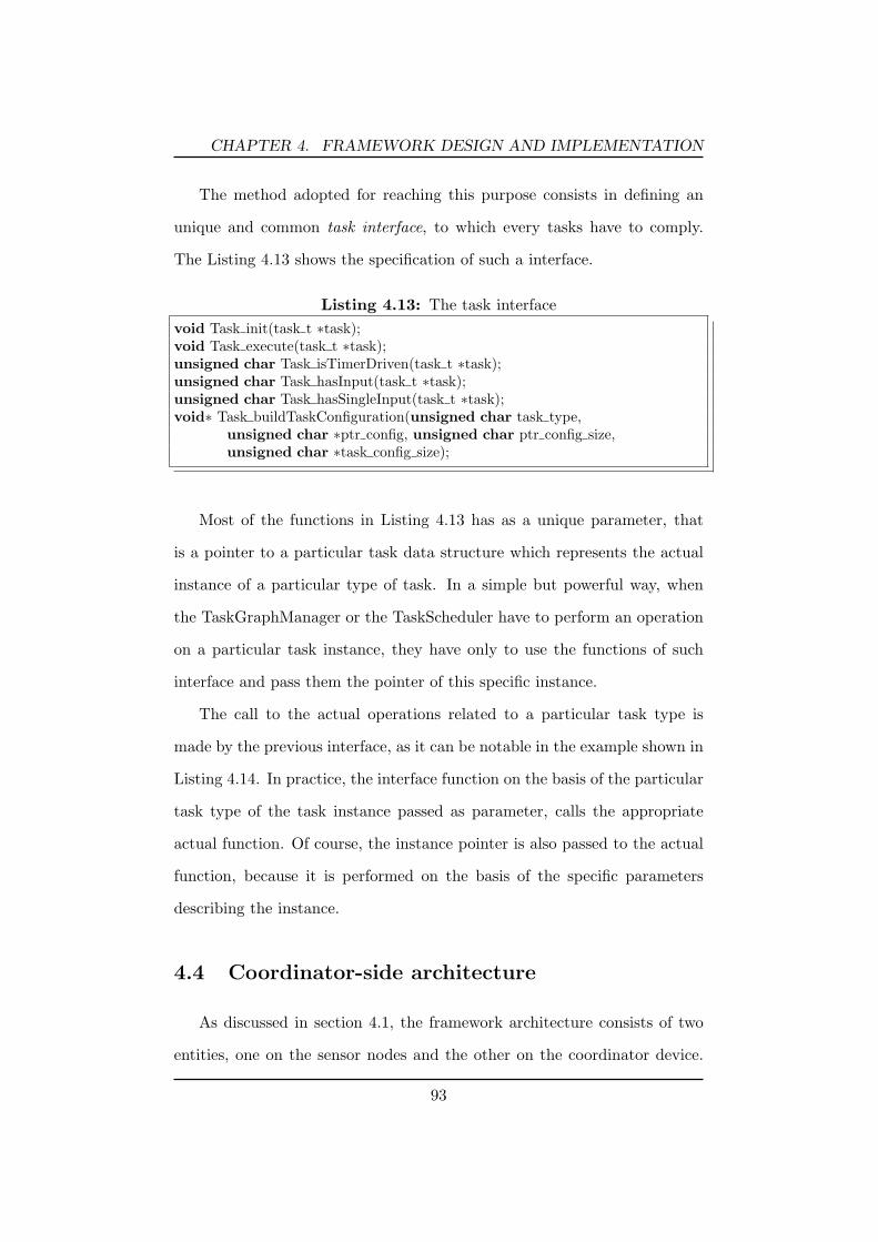
CHAPTER 4. FRAMEWORK DESIGN AND IMPLEMENTATION
The method adopted for reaching this purpose consists in defining an
unique and common task interface, to which every tasks have to comply.
The Listing 4.13 shows the specification of such a interface.
Listing 4.13: The task interfacevoid Task init(task t ∗task);void Task execute(task t ∗task);unsigned char Task isTimerDriven(task t ∗task);unsigned char Task hasInput(task t ∗task);unsigned char Task hasSingleInput(task t ∗task);void∗ Task buildTaskConfiguration(unsigned char task type,
unsigned char ∗ptr config, unsigned char ptr config size,unsigned char ∗task config size);
Most of the functions in Listing 4.13 has as a unique parameter, that
is a pointer to a particular task data structure which represents the actual
instance of a particular type of task. In a simple but powerful way, when
the TaskGraphManager or the TaskScheduler have to perform an operation
on a particular task instance, they have only to use the functions of such
interface and pass them the pointer of this specific instance.
The call to the actual operations related to a particular task type is
made by the previous interface, as it can be notable in the example shown in
Listing 4.14. In practice, the interface function on the basis of the particular
task type of the task instance passed as parameter, calls the appropriate
actual function. Of course, the instance pointer is also passed to the actual
function, because it is performed on the basis of the specific parameters
describing the instance.
4.4 Coordinator-side architecture
As discussed in section 4.1, the framework architecture consists of two
entities, one on the sensor nodes and the other on the coordinator device.
93

CHAPTER 4. FRAMEWORK DESIGN AND IMPLEMENTATION
Listing 4.14: From interface to actual implementationvoid Task execute(task t ∗task){
switch(task−>task type){case SENSING TASK: SensingTask execute(task); break;case PROCESSING TASK: ProcessingTask execute(task); break;.....default: return;
}}
Such coordinator can be a desktop computer, a laptop or even an handheld
device (a PDA or a smart-phone). The coordinator provides the user with an
access point to the WSN and thus, its main tasks are controlling the remote
nodes, supporting the user in the definition of the task-oriented application,
deploying such application and gathering all pre-elaborated data coming
from the sensor network. The idea for allowing the use of these services is
to provide a libraries with a set of high-level operations. To enhance porta-
bility, the Java programming language has been adopted for implementing
the coordinator-side part of the framework. Furthermore, it is important
to notice that none of the existing computer or mobile devices have a na-
tive wireless interface for communicating with sensor nodes. In fact, most
of them are based on the IEEE 802.15.4 communication protocol, rather
than Wi-Fi or Bluetooth. As a consequence, a portion of the implemen-
tation is strictly dependent on the particular base-station module attached
to the coordinator node for getting the appropriate radio communication
capabilities.
Entering into the specific discussion of the software architecture, Fig-
ure 4.19 shows the simplified Package Diagram of coordinator. It is com-
posed of four main package.
The communication package includes all classes needed for allowing the
94
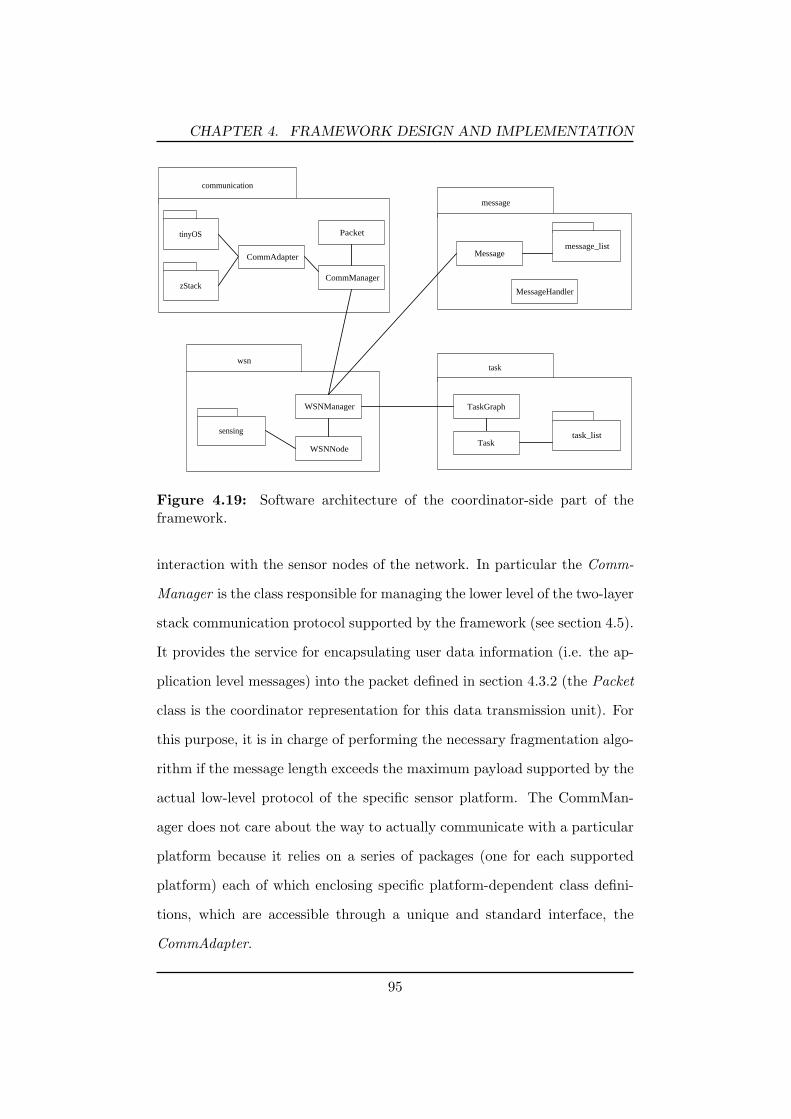
CHAPTER 4. FRAMEWORK DESIGN AND IMPLEMENTATION
communication
tinyOS
zStack
message
message_list
task
task_list
wsn
sensing
CommManager
TaskGraphWSNManager
WSNNode
Message
MessageHandler
Task
Packet
CommAdapter
Figure 4.19: Software architecture of the coordinator-side part of theframework.
interaction with the sensor nodes of the network. In particular the Comm-
Manager is the class responsible for managing the lower level of the two-layer
stack communication protocol supported by the framework (see section 4.5).
It provides the service for encapsulating user data information (i.e. the ap-
plication level messages) into the packet defined in section 4.3.2 (the Packet
class is the coordinator representation for this data transmission unit). For
this purpose, it is in charge of performing the necessary fragmentation algo-
rithm if the message length exceeds the maximum payload supported by the
actual low-level protocol of the specific sensor platform. The CommMan-
ager does not care about the way to actually communicate with a particular
platform because it relies on a series of packages (one for each supported
platform) each of which enclosing specific platform-dependent class defini-
tions, which are accessible through a unique and standard interface, the
CommAdapter.
95

CHAPTER 4. FRAMEWORK DESIGN AND IMPLEMENTATION
The wsn package is responsible for managing all the necessary infor-
mation about the particular configuration of the network. In particular,
the WSNManager contains an internal representation of the nodes included
into the network. Each node characteristics are described by the WSNNode
class, and includes information about the specific platform, the address and
the list of on-board sensors with their specifics. The WSNManager is also
responsible for managing the application-level communication protocol, i.e.
the upper layer of the two-layer stack communication protocol supported
by the framework. Hence, it manages the application-level messages (see
section 4.5). Finally, the most important purpose of the WSNManager is to
actually deploy the user defined application over the network. By accessing
the TaskGraph, it gets information about the tasks and the connections to
be deployed on every node. After having created the opportune messages
(CreateTaskMessage and CreateConnectionsMessage) it sends them through
the communication service provided by the CommManager.
The task package contains classes used to maintain a consistent repre-
sentation of the user defined task-oriented application. In particular, the
TaskGraph has the information about the set of tasks chosen by the user
and all the connections forming the final task-graph of the application. The
task list package contains the list of all tasks currently supported by the
framework and accessible through the Task common interface.
Finally, the message package enclose the list of all the defined application-
level messages and also the MessageHandler which is in charge of managing
the messages coming from the nodes of the network.
96

CHAPTER 4. FRAMEWORK DESIGN AND IMPLEMENTATION
4.5 Communication protocol
The interaction between the coordinator and the sensor nodes takes place
trough an ad-hoc communication protocol. This protocol has been conceived
as a two-layer stack, relying on top of the actual platform-dependent low-
level communication protocol provided by the on-board radio of the sensor
node (see Figure 4.20).
On-board radiolow-level format
Messages(support for
application-levelcommunication )
Packets(support for
fragmentation)
Platform-dependentprotocol
Two-layer stackplatform-independent
protocols
Figure 4.20: The framework protocol stack layers.
This two layers provides different services to both the entity involved in
the application development/execution. The lowest one has been already
discussed in the subsection 4.3.2, where it has been stated that the Comm-
Manager is the node-side component of the framework in charge of managing
it. This layer provides a simple point-to-point communication, and, most
important, it has the capability of handling the fragmentation of the en-
capsulated payload, so that the maximum payload length supported by the
radio protocol is not a limitation for the higher protocol defined above it. It
is also recalled that this first layer defines its own packet format as shown
in Figure 4.21.
The higher layer of the defined protocol consists in a set of application-
level messages that are exchanged between the coordinator and the sensor
nodes, in order to encapsulate the high-level information and commands
97

CHAPTER 4. FRAMEWORK DESIGN AND IMPLEMENTATION
Total Fragments
PACKET PAYLOAD
(Application-level Message)
8 bitVersion Future Use
8 bit
Sequence Number
Fragment Number
GroupID
Source Address
Destination Address
Figure 4.21: Packet definition.
needed for managing the user application definition and execution. In par-
ticular, the node-side component in charge of handling these messages is the
central ApplicationManager.
The messages currently defined in the framework are shown in Table 4.2.
Table 4.2: List of messages.
Message Type Source Destination
Create Task Coordinator NodeCreate Connections Coordinator NodeInit Application Coordinator NodeStart Application Coordinator NodeNode Application Ready Node CoordinatorSensor Data Node CoordinatorSensor to Sensor Data Node Node
The Create Task Message is sent by the coordinator for instantiating a
task to a remote node. Its fields shown in Figure 4.22, correspond exactly
to the information stored into the task structure (see Listing 4.9).
Similarly to the previous one, the Create Connections Message (see Fig-
98

CHAPTER 4. FRAMEWORK DESIGN AND IMPLEMENTATION
Task Code Task Location
Task Configuration
(variable size)
8 bit 8 bitCREATE_TASK_MSG Task Type
Figure 4.22: Task Creation message.
ure 4.23) is sent by the coordinator during the deployment phase. It encloses
all the information regarding the output connections related to a specific task
instantiated on a node. So, it contains the list of the destination task codes,
and when necessary (i.e. when the destination task is not locally instanti-
ated), the addresses of the remote nodes on which the destination task are
placed. Furthermore, this message encloses the information for configuring
the buffers on each output connection.
After having configured the distributed application on the network, the
user can decide to issue a Init Message for initializing the whole application.
When all nodes have replied with a Node Application Ready Message (see
in the following), the application is ready to start. Then, the user can issue
a Start Message which cause the application to run. Both messages (see
Figure 4.24) have no additional info and are sent in broadcast to all nodes
forming the network involved in the user application.
As previously mentioned, the Node Application Ready Message is sent
by a node to the coordinator in response to the Init Message. The only
information it encloses (see Figure 4.25) is the address of the node in which
the all instantiated tasks of the application have been initialized.
The Sensor Data Message is used by the node when new computed sensor
data have to be sent to the coordinator. Its fields are shown in Figure 4.26.
99

CHAPTER 4. FRAMEWORK DESIGN AND IMPLEMENTATION
Destination Task Nr Remote Nodes Nr
Connection Buffers Configuration
(variable size)
8 bit 8 bitCREATE_CONNECTIONS_MSG Source Task Code
Destination Task Code (1) Destination Task Code (2)
......... .........
Destination Task Code (n-1) Destination Task Code (n)
Remore Node Address (1)
Remore Node Address (m)
.........
Figure 4.23: Connections Creation message.
8 bit 8 bitINIT_APPLICATION_MSG START_APPLICATION_MSG
Figure 4.24: Init and Start message.
Finally, the Sensor to Sensor Data Message is fundamental in the con-
text of a distributed application. In fact, it is used by a node when the
transmission of data have to be made from a local terminated task to a
remote destination task. Its fields are shown in Figure 4.27.
4.6 Application development cycle
In the previous sections the software architectures of the two entities
(coordinator and sensor node) constituting the framework and their main
purposes have been discussed. In this section more information on the dy-
100

CHAPTER 4. FRAMEWORK DESIGN AND IMPLEMENTATION
8 bit 16 bitNODE_APPLICATION_READY_MSG Node Address
Figure 4.25: Node Application Ready message.
Buffer Size (1) Buffer Size (2)
DATA Buffer (1)
( size: 16*buffer_size_1 )
8 bit 8 bitSENSOR_DATA_MSG Buffers Nr
....... ........
DATA Buffer (n)
( size: 16*buffer_size_n )
..........
....... Buffer Size (n)
Figure 4.26: Sensor Data message.
namics involved into the application development process are provided.
Substantially, the whole application development cycle can be summa-
rized in the following steps:
1. the user specifies the high-level application behavior on the basis of its
aims and purposes, and then depending on the particular requirements
of the context.
2. the user translates the application behavior into a task-oriented rep-
resentation by using the constructs made available by the definition
language discussed in 4.2. This phase consists in choosing what tasks
101

CHAPTER 4. FRAMEWORK DESIGN AND IMPLEMENTATION
Destination Task Code Buffers Nr
DATA Buffer (1)
( size: 16*buffer_size_1 )
8 bit 8 bitSENSOR_TO_SENSOR_DATA_MSG Source Task Code
Buffer Size (1) ........
DATA Buffer (n)
( size: 16*buffer_size_n )
..........
....... Buffer Size (n)
Figure 4.27: Sensor to Sensor Data message.
have to be included to form the whole application and mainly how
they are connected each others to define the work flow of the comput-
ing process.
3. through the libraries provided by the coordinator-side part of the
framework, the previous task-oriented conceptual representation is
translated into a computational model. The user also configure the
application execution specifics by setting the parameters related to
every task.
4. after having defined the whole application, the user has to specify the
deployment parameters by choosing which part of the application (i.e.
a set of tasks) has to be instantiated on each sensor node compos-
ing the network. The only constraint is that each single task can be
instantiated on one specific node.
102

CHAPTER 4. FRAMEWORK DESIGN AND IMPLEMENTATION
5. the actual deployment process can take place. The coordinator tool
after having analyzed the application description model previously de-
fined by the user, automatically start the actual deployment of the ap-
plication on the network. This process consists in transmitting a series
of application-level messages (defined in 4.5) to every node involved
in the application. These messages encapsulate all needed information
regarding the tasks and the connections that have to be instantiated
on the nodes.
6. the deployed distributed application, after an initialization phase, is
now ready to execute.
7. during its execution, the application may send the processed data to
the coordinator for further heavy-elaboration or only to show results
to the user. This depends on the particular specification of the appli-
cation. Moreover, additional Java applications may be developed on
top of the coordinator-side part of the framework and interfaced with
it for retrieving all desired data coming from the WSN application and
eventually performing further intensive elaboration on them.
From the node perspective, the application life cycle starts when it begin
to receive messages containing information on the tasks and connections to
be instantiated. Before a task is ready to be executed, it passes trough an
initialization phase in which it can eventually initialize any data structure or
even dynamically allocate memory space (in particular data buffers) needed
for its execution. When all tasks on a node complete the initialization phase,
the node communicates the coordinator that it is ready to start.
When all nodes of the sensor network are ready, the user can issue a
103

CHAPTER 4. FRAMEWORK DESIGN AND IMPLEMENTATION
”start command” so that the distributed application can start running. At
this point, the timers related to every timed tasks in the application are
activated.
The task execution semantic is the following: a task is ready to be exe-
cuted when all the input connections are in the ”active” status, which means
that all the input tasks have terminated their execution.
On the basis of the previous semantic rule, the first tasks that will be
ready to execute will be the ones without any input connections, i.e. the
tasks driven by a timer (all included into the TimedTask category), which
are the first scheduled for execution on timers expiration.
After their execution and as a consequence of their termination, these
tasks will put their data results on the output connections and will set the
connections status to CONN ACTIVATE, indicating that the tasks output
data are ready and available for the destination tasks. Furthermore, the
same tasks will notify the TaskScheduler that they have terminated, so that
it is able to verify if some of the following tasks are ready. If that is the
case, these tasks are scheduled for execution.
The runtime engine of the framework is able to prevent any data incon-
sistency situation during tasks application execution. Let suppose that two
tasks, name it A and B, are connected together (A → B). When A termi-
nates, it sets the connection to CONN ACTIVE causing B to be executed.
The ”active”status remains, as long as B is using the data on the connection.
This condition prevents A from overwriting on its output connection, avoid-
ing B accessing inconsistent data over time. Only when B does not need its
input data anymore, can set the input connection to CONN INACTIVE, so
that A regain the permission for writing on its output connections buffers.
104

CHAPTER 4. FRAMEWORK DESIGN AND IMPLEMENTATION
4.7 A case study: human activity recognition
The capabilities of the proposed framework are demonstrated by de-
veloping a real application. In particular, the sensor-node side application
presented in [19] is designed and implemented by following the development
methodologies reported in section 4.6. The application is able to recognize
postures and movements of individuals (e.g. standing, lying, walking, sit-
ting, and falling), and is based on a classifier running on the coordinator
and two different node-side applications running on two nodes placed on the
waist and on the thigh of a person. Each node mounts the SPINE sensor
board which enclose an accelerometer.
The first node application (on the waist) consists in sampling data from
the accelerometer and computing three different feature extractions on them.
The results are aggregated before sending them to the coordinator. The
second application (on the thigh) consists in a single feature extraction.
The two node-side application have been modeled through the definition
language presented in section 4.2, which includes the parameter settings for
every single task.
Every task is defined by a type, a name which should be unique for a
same application, and its parameter settings.
In Figure 4.28 the application running on the waist node is depicted.
It samples the accelerometer data from all the three axis periodically every
25ms. The data are split toward three different ProcessingTask (configured
as max, mean and min functions). All the three results are then aggregated
together before being sent to the coordinator (see the BASE STATION pa-
rameter setting).
The application running on the thigh node is shown in Figure 4.29. It
only computes the min value, before sending result to the coordinator.
105

CHAPTER 4. FRAMEWORK DESIGN AND IMPLEMENTATION
ag{ PARAMS: inCount= 3;}trans {
PARAMS: destination= BASE_STATION;}
accelerometer{ PARAMS: sensingType= AccXYZ, isPeriodic= true, period= 25, timeScale= mills, channelSelection= [true,true,true];}sp{ PARAMS: outCount= 3, selOut[1]= [true,false,false], selOut[2]= [true,true,true], selOut[3]= [true,false,false];}
Sensingaccelerometer
Splitsp
< AccX, AccY,AccZ >
Processingmean
Processingmin
Processingmax
< AccX, AccY,AccZ > as AccXYZ
AccX
AccX
Aggrag
Mean (AccXYZ)
Min(AccX)
Max(AccX)
Transmissiontrans
<Max(AccX),Mean(AccXYZ),
Min(AccX)>
max{ PARAMS: processingType= MAX, preCond= true, postCond= true, window= 80, shift= 20,}
min{ PARAMS: processingType= MIN, preCond= true, postCond= true, window= 80, shift= 20,}
mean{ PARAMS: processingType= MEAN, preCond= true, postCond= true, window= 80, shift= 20,}
Figure 4.28: Application running on the waist node.
The results coming from the two applications are then evaluated by
a classifier running on the coordinator. This specific activity recognition
application has been shown to demonstrate the capabilities of the framework
in modeling and implementing a typical signal-processing application.
The specifications of this application does not include the possibility for
a distributed elaboration, but it can be easily extended by splitting the first
application task graph into two different subset of tasks, each of which can
be placed in a different node. Of course, the node running the sensing task
have to be placed on the waist, whereas the second is free to be placed
everywhere because it does not execute any sensing operation and then it
is not required to be ”near” a physical event to detect. Figure 4.30 shows a
possible partition for the ”waist” application.
106

CHAPTER 4. FRAMEWORK DESIGN AND IMPLEMENTATION
Sensingaccelerometer
Processingmin
AccX Min(AccX) Transmissiontrans
accelerometer{ PARAMS: sensingType= AccXYZ, isPeriodic= true, period= 25, timeScale= mills, channelSelection= [true,false,false];}
min{ PARAMS: processingType= MIN, preCond= true, postCond= true, window= 80, shift= 20,}
trans{ PARAMS: destination= BASE_STATION;}
Figure 4.29: Application running on the thigh node.
Sensingaccelerometer
Splitsp
< AccX, AccY,AccZ >
Processingmean
Processingmin
Processingmax
< AccX, AccY,AccZ > as AccXYZ
AccX
AccX
Aggrag
Mean (AccXYZ)
Min(AccX)
Max(AccX)
Transmissiontrans
<Max(AccX),Mean(AccXYZ),
Min(AccX)>
NODE 1
NODE 2
Figure 4.30: The ”waist” application distributed on two nodes.
107

Chapter 5Evaluation
In this chapter an evaluation of the previously discussed framework ar-
chitecture is provided for motivating the use of such a tool as an effective
and easy software support for a rapid development of applications on wireless
sensor networks.
In particular, the main purpose of the obtained results is to demonstrate
that it is actually feasible to achieve a very high programming abstraction
level without the need to make compromises with the runtime performance.
As it has been discussed in chapter 2 there exist many middlewares in lit-
erature that have been proposed for providing approaches and high-level
constructs to model an application on the basis of the context requirements,
without facing with low level programming details. Unfortunately, many of
them come with underlying runtime mechanisms that impose high resource
requirements to node such that the user programs are executed with limited
running performance.
Differently from these middlewares, the proposed framework has been
developed for guaranteeing a very lightweight application execution engine.
Thanks to the integration of the task-oriented application modeling and
108

CHAPTER 5. EVALUATION
the software layering architectural approach, it is ensured that no excessive
overhead can lead to performance penalties.
Different aspects have been taken in consideration for proving the effi-
ciency and the effectiveness of the previously mentioned choices for devel-
oping the framework.
In particular, measurements of processing and transmission performance
of the node-side part of the middleware are carry out for understanding how
it can be suitable for resource constrained environments such as the sensor
nodes.
It is worth noting that all the following tests and considerations are
concerning the framework implementation running on top of the TinyOS
operating system [10, 17, 25]. The particular sensor nodes employed is the
well known TmoteSky [11] platform, based on the 8Mhz MSP430 microcon-
troller (10k RAM, 48k Flash).
5.1 Computational performance
Since this framework has been mainly conceived for supporting the de-
velopment of distributed signal processing applications, the primary need
requested by such applications is to execute different kind of processing
functions on the sensed data, directly on the node. The framework provides
such processing services by making available the ProcessingTask, one of the
the high-level constructs discussed in section 4.2.1 and supported by the ap-
plication runtime system. Through this basic element, the user can choose
which functions and algorithms he needs for its own application.
A specific type of functions are named feature extractions which represent
particular math functions (e.g., max, min, standard deviation, etc).
109

CHAPTER 5. EVALUATION
As many of the signal processing applications are developed for the ac-
tivity recognition context, they require an efficient execution performance in
order to be successfully employed for evaluating data coming from sensors
with high sampling rates. To satisfy this requirement, the task execution
model of the middleware is designed and implemented to guarantee a very
high efficiency, although, at the same time, it exposes a simple and intuitive
programming abstraction.
In the following, the performance results of some evaluation tests on the
ProcessingTask are presented. These tests have been executed on a simple
application deployed on a node, and involves a SensingTask connected to
the ProcessingTask. It has the aim at providing the sensed data for the
computation. Furthermore, in each test the task is configured to perform
a particular function, representing the main configurable parameter for the
task.
The purpose of the tests is to show how the execution time varies over
different dimension of the data window, and over different values for the
selected channels. It is recalled that the channels can be assumed as the
dimension of the ”output” for each sensor (and then for the SensingTask),
i.e. how many sensed data are available on every sensing operation. For
example, a tri-axial accelerometer has three channels, one for each axis,
whereas a temperature sensor provide a single data vale (only one channel).
In a certain sense, this means that the ProcessingTask can be evaluated over
a different number of distinctive input buffers.
Table 5.1 and Table 5.2 show the different temporal executions of the
ProcessingTask configured for performing the functions min, mean, standard
deviation, vector magnitude and pitch and roll on the input data. The
110

CHAPTER 5. EVALUATION
last function, in particular, is expressly used only on three channels data,
representing the x, y, and z axis values of an accelerometer sensor.
Moreover, it is worth noting that each listed value does not represent a
precise and unique task execution time but, instead, represents an averaged
value computed over many performed task execution.
Table 5.1: ProcessingTask execution time.execution time (ms)
window channels Min Mean Standard deviation
101 0.5188 0.6729 1.69532 0.6082 0.7007 2.90663 0.6714 0.9414 3.9971
501 0.6698 0.8536 3.09532 0.8542 1.2207 5.68333 1.0672 1.6794 8.1963
1001 0.7947 1.1180 3.14712 1.1889 1.5875 9.79693 1.5551 2.1667 15.6871
1501 1.0052 1.2145 7.61522 1.5259 1.9842 14.65783 2.0468 2.7767 21.7845
2001 1.1291 1.5268 9.41672 1.8024 2.3498 18.36253 2.5323 3.2968 27.5363
All the values listed on these two tables can be also reported on a se-
ries of charts (Figure 5.1, Figure 5.2, Figure 5.3, Figure 5.4, Figure 5.5),
each of which illustrating the execution performance of the ProcessingTask
configured with a particular function.
By consulting such information, a developer can understand if a partic-
ular task is able to support the data rate processing required by its own
application. But, on the basis of these performance results, it appears quite
obvious that the task runtime engine can quietly support very high data
rate processing, demonstrating that it does not generate incisive overhead
during the execution of the user application.
111

CHAPTER 5. EVALUATION
Table 5.2: ProcessingTask execution time.execution time (ms)
window channels Vector magnitude Pitch and Roll
101 1.40012 1.81043 2.0955 17.8158
501 1.66092 3.16643 4.6475 18.1404
1001 2.07522 5.15153 8.1866 18.7094
1501 2.57142 7.48253 7.4825 19.3148
2001 2.95242 9.38103 15.8195 19.8219
5.2 Data transmission performance
As already stated, the main purpose of the proposed framework is to
allow users in developing distributed signal processing applications. The
distributed key concept means that nodes collaborate together for reaching
a common aim that is the aim of the whole application considered as a
unique entity. In fact, the task-oriented application representing the entire
processing work flow is split into different and disjunctive parts, such that
each of them is designated to be executed on a single node of the network.
The critical point in this approach is that the data flowing among the
tasks have to be necessarily exchanged over the wireless communication link.
Locally to a node, the data on a connection are not explicitly passed
from the source task to the destination one because this data exchange is
simply made by sharing a same common set of buffers allocated on the con-
112

CHAPTER 5. EVALUATION
2 5
3
2
2,5
1 5
2
ms 1 channel
1
1,5ms 1 channel
2 channels
3 channels
0,5
0
10 50 100 150 200
window size
Figure 5.1: ProcessingTask execution time, with the ”Min” function asparameter.
nection instantiation. A different situation is obviously when the connection
connects two tasks placed and instantiated on different nodes. In this case
the underlying application execution engine has to support the delivery of
the source task data results to the destination task data input.
Since this is a necessary requirements, it is very important to evaluate
how much the framework affects the transmission of data from a task to
a remote one. In particular, on the basis of the amount of data to be
transmitted, three different performance indexes are considered:
- the total fragmented packets required for transmitting the user data;
- the total amount of transmitting bytes in relation to the amount of
the actual user data to be exchanged;
- the time needed for ”packetizing” data (including also possible frag-
mentation process), and transmitting them.
113

CHAPTER 5. EVALUATION
3
3,5
2,5
3
2ms 1 channel
1
1,5ms 1 channel
2 channels
3 channels
0,5
1
0
,
10 50 100 150 200
window size
Figure 5.2: ProcessingTask execution time, with the ”Mean” function asparameter.
From the above considered indexes, it appears obvious that their real
values strongly depend on the actual sensor platform and mainly on its
communication protocol. In particular, the factors that directly influence
them are the maximum payload supported by the underlying protocol and
its data rates.
As in the case of the performance evaluation of the framework, the fol-
lowing tests have been performed adopting the TmoteSky platform running
the TinyOS operating system on which the framework is currently available.
Hence, the communication protocol is the IEEE802.15.4, whereas the maxi-
mum supported payload is that of the Active Message defined by the TinyOS
and consists in 28 bytes. Then, on the basis of the packet format defined
by the framework for its own communication protocol (see section 4.3.2) it
is clear that the payload available on each packet for user data transmission
114

CHAPTER 5. EVALUATION
25
30
20
25
15
20
ms 1 channel
10
15ms 1 channel
2 channels
3 channels
5
0
10 50 100 150 200
window size
Figure 5.3: ProcessingTask execution time, with the ”Standard deviation”function as parameter.
is of 19 bytes.
A first test results are shown in Figure 5.6. The chart depict how many
fragments are needed on the basis of the amount of user data to be sent over
the radio.
The second test exhibits how much extra data overhead are transmitted
together with the application-level information encapsulated into the mes-
sages defined in 4.5. This values are directly correlated to the number of
fragments previously tested and are shown in Figure 5.7.
Finally, the last test consists in analyzing the total time needed for the
transmission of the user data. Results are shown in Figure 5.8.
115

CHAPTER 5. EVALUATION
16
18
12
14
10
12
ms 1 channel
6
8ms 1 channel
2 channels
3 channels
4
0
2
10 50 100 150 200
window size
Figure 5.4: ProcessingTask execution time, with the ”Vector magnitude”function as parameter.
5.3 Memory usage
In this section an evaluation of the program memory usage is provided.
In Table 5.3 the memory amount needed both for the platform-independent
”core framework” and for the platform-dependent modules (it encloses the
sensor drivers included in the framework so far) is shown. In Figure 5.9 is
simply depicted their memory occupation percentage in relation to the whole
framework. It is worth noting that the platform-dependent part may change
over time, as a consequence of the inclusion of new sensor drivers. The mem-
ory size indicated into the table comprises the drivers of the two internal
sensors (temperature and voltage) of the TmoteSky platform, plus a driver
supporting the SPINE sensor board, a sensor board specifically developed
for the SPINE project (see section 3.1).
In Table 5.4 more detailed information on the amount of memory needed
116

CHAPTER 5. EVALUATION
19,5
20
19
,
18,5
ms
18
ms
3 channels
17
17,5
16,5
17
10 50 100 150 200
window size
Figure 5.5: ProcessingTask execution time, with the ”Pitch and Roll” func-tion as parameter.
Table 5.3: Memory usage comparison between the ”core framework” andthe platform-dependent components.
Program memory occupation (bytes)
Adaptation components 18870Core framework 7356
for each component composing the platform-dependent part is provided.
The memory needed for a plain TinyOS (with no loaded components) and for
the printf library, which is important during debug phase, are also provided.
In Figure 5.10 their relative memory occupation are depicted.
117

CHAPTER 5. EVALUATION
14
10
12
8
10
Fragments
6
gnumber
2
4
0
2
10 20 40 80 120 150 192 240
User data bytes
Figure 5.6: Packet fragments required for transmitting user data.
350
400
300
350
200
250Total bytes
t b
150
200to betransmitted
user data
data overhead
50
100
0
50
10 20 40 80 120 150 192 240
User data bytes
Figure 5.7: Comparison between the amount of user data to be transmittedand the extra overhead needed for packets fragmentation.
118

CHAPTER 5. EVALUATION
10
12
8
10
6
8
Time
4
6(ms)
2
0
10 20 40 80 120 150 192 240
User data bytes
Figure 5.8: Time needed to transmit user data among tasks.
28%28%
72%
Adaptation components
Core Framework
Figure 5.9: Program memory usage.
119
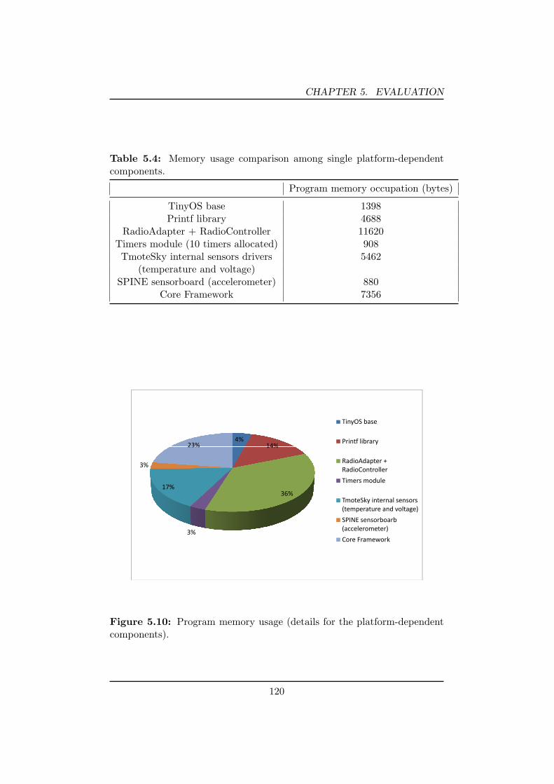
CHAPTER 5. EVALUATION
Table 5.4: Memory usage comparison among single platform-dependentcomponents.
Program memory occupation (bytes)
TinyOS base 1398Printf library 4688
RadioAdapter + RadioController 11620Timers module (10 timers allocated) 908
TmoteSky internal sensors drivers 5462(temperature and voltage)
SPINE sensorboard (accelerometer) 880Core Framework 7356
Ti OS b
4%14%23%
TinyOS base
Printf library14%
3%
23%
RadioAdapter + RadioController
36%17%
Timers module
TmoteSky internal sensorsTmoteSky internal sensors (temperature and voltage)
SPINE sensorboarb ( l t )3% (accelerometer)
Core Framework
Figure 5.10: Program memory usage (details for the platform-dependentcomponents).
120

Chapter 6Conclusion and future work
Wireless sensor networks are a powerful technology for supporting a lot
of different real-world applications. Unfortunately, the main obstacle to
their wide diffusion is the lack of easiness in programming them.
This thesis has been conceived for looking into the problems program-
mers have to tackle during the hard task of developing software on a wireless
sensor network.
After having analyzed all the major challenges and problems related
to the programming issues, it has remarked the motivations that have led
current researchers to concentrate their efforts in formulating new applica-
tion design approach and new implementation methodologies, for addressing
these programming problems and supporting users in a fast and effective de-
velopment of applications.
A detailed discussion on the different programming paradigms has been
provided, whereas the current available middlewares (providing implemen-
tation based on this programming paradigms) have been also analyzed. The
examination of the current situation has highlighted that many of the ex-
istent middlewares do not provide general purpose distributed computation
121
CHAPTER 6. CONCLUSION AND FUTURE WORK
so that they are not suitable for application domains requiring more so-
phisticated collaborative sensor data processing in the network. This is
an important missing characteristic for many applications, such as context
recognition, health monitoring, and medical assistance, which will become
crucial in the future.
These are valid motivations to presume that a new software framework
may be a requirement for enabling intensive distributed signal-processing-
based applications.
For this reason, a new framework for a rapid and effective application
development has been proposed. It aims at defining all functions and prop-
erties of the applications in an accurate way by providing users an intuitive
and straightforward design model based on a task-oriented approach and
relying on a simple but formal high-level language. In particular, the frame-
work designed and implemented in this work has been conceived to satisfy
three desirable requirements:
• the need for methodologies and models for translating high-level speci-
fications designed by a developer into an actual executable application
running over a real wireless sensor network;
• the need for a tool that allow building applications without any kind
of deep knowledge about the specific sensor platforms adopted;
• the need for an instrument able to deploy a same application on dif-
ferent sensor architectures in a transparent way for the developer.
According to such requirements, the adopted task-oriented paradigm
provides a way to conceive a graphical high-level behavior of the applica-
tion by the use of an high-level language, which exposes a set of constructs
specifically defined for supporting such a approach. With respect to this
122
CHAPTER 6. CONCLUSION AND FUTURE WORK
methodology an application can be simply specified as a set of tasks con-
nected together, where each task represents a particular activity, such as a
sensing operation, a processing function or a radio data transmission. More-
over, the framework supports a distributed data processing so that the users
can decide where each task forming the application is allocated over the
sensor network.
The software architecture in charge of providing all the aforementioned
characteristics and services, is composed of two components: one is imple-
mented on the WSN coordinator (i.e. it is a Java application running on a
laptop), the other is implemented on the sensor nodes. Through the former
the user configures and manages the sensor network and the task-application
to be deployed on it. The latter represents the middleware engine running
on top of the sensor node operating system. It is responsible for handling
the messages coming from the coordinator which are used, among the other
things, for configuring the portion of the user application assigned to the
node. It is also in charge of managing and executing the tasks that are
instantiated on the node.
Currently, the node-side part of the framework has been implemented
and tested on top of the TinyOS operating system but, it has been also
discussed that the modular and platform-independent approach used for
designing it allows a fast porting to others C-like software architecture.
All the services and features supported by the framework should motivate
the use of such a tool as an effective and easy software support for a rapid
development of applications on wireless sensor networks. In particular, it has
been shown that, although the framework achieves a very high programming
abstraction level, thanks to the integration of the task-oriented application
modeling and the software layering architectural approach, it comes with
123

CHAPTER 6. CONCLUSION AND FUTURE WORK
a very lightweight application execution engine, so as to ensure that no
excessive overhead can lead to runtime performance penalties.
6.1 Future work
Since the software architecture of the node-side part of the framework
has been designed according to the software layering approach, the strong
decoupling between the core and the adaptation modules let to easily port
the whole framework to new C-like sensor platforms.
Hence, together with the current support for the TinyOS-based system,
the framework will be port to other widespread architectures. For example,
the next step is to provide the necessary adaptation modules for making
available the use of the framework on top of the Z-Stack platform, which
ensures the ability to deal with the more and more growing ZigBee compliant
devices.
Of course, the aforementioned ”decoupling” characteristic may be useful
not only to provide a new complete porting, but also to simply add new
platform-dependent modules (drivers) for making new sensor devices avail-
able.
Concerning the only node core part of the framework, its modular design
is naturally incline to further enrichment, so as to extend the functionalities
and the services provided to developers.
First of all, the primary requirement is to broaden the currently sup-
ported set of tasks with new ones, so as to enlarge the framework capability
with new functions and new algorithms.
Moreover, the communication module can be enhanced to support a
new protocol without the limitations imposed by the simple point-to-point
communication, but enabling a more useful routing protocol.
124

CHAPTER 6. CONCLUSION AND FUTURE WORK
Concerning the coordinator-side part of the framework, the services cur-
rently available for the deployment of an application on the network will
be empowered for providing more functionalities, such as on-demand node
querying for gathering information on its state. Furthermore, a friendly
graphical user interface will be provided to developers for allowing them a
simplified and more effective application configuration.
125

Bibliography
[1] Francesco Aiello, Giancarlo Fortino, Raffaele Gravina, and AntonioGuerrieri. Maps: a mobile agent platform for java sun spots. In Pro-ceedings of the 3rd International Workshop on Agent Technology forSensor Networks (ATSN-09), 2009.
[2] I. F. Akyildiz, W. Su, Y. Sankarasubramaniam, and E. Cayirci. Wirelesssensor networks: a survey. Computer Networks, 38(4):393–422, 2002.
[3] Th. Arampatzis, J. Lygeros, and S. Manesis. A survey of applicationsof wireless sensors and wireless sensor networks. In Intelligent Con-trol, 2005. Proceedings of the 2005 IEEE International Symposium on,Mediterrean Conference on Control and Automation, pages 719–724,june 2005.
[4] Amol Bakshi, Viktor K. Prasanna, Jim Reich, and Daniel Larner. Theabstract task graph: a methodology for architecture-independent pro-gramming of networked sensor systems. In EESR ’05: Proceedings ofthe 2005 workshop on End-to-end, sense-and-respond systems, appli-cations and services, pages 19–24, Berkeley, CA, USA, 2005. USENIXAssociation.
[5] Shah Bhatti, James Carlson, Hui Dai, Jing Deng, Jeff Rose, An-mol Sheth, Brian Shucker, Charles Gruenwald, Adam Torgerson, andRichard Han. Mantis os: an embedded multithreaded operating systemfor wireless micro sensor platforms. Mob. Netw. Appl., 10(4):563–579,2005.
126

[6] P. Bonnet, J. Gehrke, and P. Seshadri. Querying the physical world.Personal Communications, IEEE, 7(5):10–15, oct 2000.
[7] Philippe Bonnet, Johannes Gehrke, and Praveen Seshadri. Towardssensor database systems. In MDM ’01: Proceedings of the Second Inter-national Conference on Mobile Data Management, pages 3–14, London,UK, 2001. Springer-Verlag.
[8] Athanassios Boulis, Chih-Chieh Han, and Mani B. Srivastava. Designand implementation of a framework for efficient and programmable sen-sor networks. In MobiSys ’03: Proceedings of the 1st international con-ference on Mobile systems, applications and services, pages 187–200,New York, NY, USA, 2003. ACM.
[9] Shih-Lun Chen, Ho-Yin Lee, Chiung-An Chen, Chin-Chun Lin, andChing-Hsing Luo. A wireless body sensor network system for health-care monitoring application. In Biomedical Circuits and Systems Con-ference, 2007. BIOCAS 2007. IEEE, pages 243–246, nov. 2007.
[10] TinyOS Community. Tinyos web site: http://www.tinyos.net, (Lastvisited April 2010).
[11] Sentilla Corporation. Moteiv hardware products:http://www.sentilla.com/moteiv-transition.html, (Last visited March2010).
[12] Adam Dunkels, Bjorn Gronvall, and Thiemo Voigt. Contiki - alightweight and flexible operating system for tiny networked sensors.In LCN ’04: Proceedings of the 29th Annual IEEE International Con-ference on Local Computer Networks, pages 455–462, Washington, DC,USA, 2004. IEEE Computer Society.
[13] Ember. Ember web site: http://www.ember.com, (Last visited April2010).
[14] Deborah Estrin, David Culler, Kris Pister, and Gaurav Sukhatme. Con-necting the physical world with pervasive networks. IEEE PervasiveComputing, 1(1):59–69, 2002.
[15] Chien-Liang Fok, Gruia-Catalin Roman, and Chenyang Lu. Rapid de-velopment and flexible deployment of adaptive wireless sensor network
127

applications. In ICDCS ’05: Proceedings of the 25th IEEE Interna-tional Conference on Distributed Computing Systems, pages 653–662,Washington, DC, USA, 2005. IEEE Computer Society.
[16] Chien-Liang Fok, Gruia-Catalin Roman, and Chenyang Lu. Agilla:A mobile agent middleware for self-adaptive wireless sensor networks.ACM Trans. Auton. Adapt. Syst., 4(3):1–26, 2009.
[17] David Gay, Phil Levis, and David Culler. Software design patternsfor tinyos. In LCTES ’05: Proceedings of the 2005 ACM SIG-PLAN/SIGBED conference on Languages, compilers, and tools for em-bedded systems, pages 40–49, New York, NY, USA, 2005. ACM.
[18] David Gay, Philip Levis, Robert von Behren, Matt Welsh, Eric Brewer,and David Culler. The nesc language: A holistic approach to networkedembedded systems. In PLDI ’03: Proceedings of the ACM SIGPLAN2003 conference on Programming language design and implementation,pages 1–11, New York, NY, USA, 2003. ACM.
[19] R. Gravina, A. Guerrieri, G. Fortino, F. Bellifemine, R. Giannantonio,and M. Sgroi. Development of body sensor network applications us-ing spine. In Systems, Man and Cybernetics, 2008. SMC 2008. IEEEInternational Conference on, pages 2810–2815, oct. 2008.
[20] Ramakrishna Gummadi, Omprakash Gnawali, and Ramesh Govin-dan. Macro-programming wireless sensor networks using kairos. InInternational Conferenceon Distributed Computing in Sensor Systems(DCOSS), 2005.
[21] Ramakrishna Gummadi, Nupur Kothari, Ramesh Govindan, and ToddMillstein. Kairos: a macro-programming system for wireless sensornetworks. In SOSP ’05: Proceedings of the twentieth ACM symposiumon Operating systems principles, pages 1–2, New York, NY, USA, 2005.ACM.
[22] Salem Hadim and Nader Mohamed. Middleware: Middleware chal-lenges and approaches for wireless sensor networks. IEEE DistributedSystems Online, 7(3):1, 2006.
128

[23] W.B. Heinzelman, A.L. Murphy, H.S. Carvalho, and M.A. Perillo.Middleware to support sensor network applications. Network, IEEE,18(1):6–14, jan/feb 2004.
[24] Karen Henricksen and Ricky Robinson. A survey of middleware forsensor networks: state-of-the-art and future directions. In MidSens ’06:Proceedings of the international workshop on Middleware for sensornetworks, pages 60–65, New York, NY, USA, 2006. ACM.
[25] Jason Hill, Robert Szewczyk, Alec Woo, Seth Hollar, David Culler, andKristofer Pister. System architecture directions for networked sensors.SIGOPS Oper. Syst. Rev., 34(5):93–104, 2000.
[26] Jonathan W. Hui and David Culler. The dynamic behavior of a datadissemination protocol for network programming at scale. In SenSys’04: Proceedings of the 2nd international conference on Embedded net-worked sensor systems, pages 81–94, New York, NY, USA, 2004. ACM.
[27] Texas Instrument. Zstack web site:http://focus.ti.com/docs/toolsw/folders/print/z-stack.html, (Lastvisited April 2010).
[28] Holger Karl and Andreas Willig. Protocols and Architectures for Wire-less Sensor Networks. Wiley-Interscience, 2007.
[29] Philip Levis and David Culler. Mate: a tiny virtual machine for sensornetworks. SIGARCH Comput. Archit. News, 30(5):85–95, 2002.
[30] S. Li, S. Son, and J. Stankovic. Event detection services using dataservice middleware in distributed sensor networks. TelecommunicationSystems, 26:351–368, 2004.
[31] Suet-Fei Li, Roy Sutton, and Jan Rabaey. Low power operating systemfor heterogeneous wireless communication system. pages 1–16, 2003.
[32] Clemens Lombriser, Nagendra B. Bharatula, Daniel Roggen, and Ger-hard Troster. On-body activity recognition in a dynamic sensor net-work. In BodyNets ’07: Proceedings of the ICST 2nd internationalconference on Body area networks, pages 1–6, ICST, Brussels, Bel-gium, Belgium, 2007. ICST (Institute for Computer Sciences, Social-Informatics and Telecommunications Engineering).
129

[33] Clemens Lombriser, Daniel Roggen, Mathias Stager, and GerhardTroster. Titan: A tiny task network for dynamically reconfigurableheterogeneous sensor networks. In 15. Fachtagung Kommunikationin Verteilten Systemen (KiVS), Informatik aktuell, pages 127–138.Springer, 0 2007.
[34] Samuel R. Madden, Michael J. Franklin, Joseph M. Hellerstein, andWei Hong. Tinydb: an acquisitional query processing system for sensornetworks. ACM Trans. Database Syst., 30(1):122–173, 2005.
[35] P.J. Marron, A. Lachenmann, D. Minder, J. Hahner, R. Sauter, andK. Rothermel. Tinycubus: a flexible and adaptive framework sensornetworks. pages 278–289, jan.-2 feb. 2005.
[36] Wassim Masri and Zoubir Mammeri. Middleware for Wireless SensorNetworks: Approaches, Challenges, and Projects. In , IEEE Inter-national Conference on Signal Processing and Communications (IC-SPC 2007), Dubai, UAE, 24/11/2007-27/11/2007, page (electronicmedium), http://www.ieee.org/, novembre 2007. IEEE.
[37] R. Newton, G. Morrisett, and M. Welsh. The regiment macroprogram-ming system. pages 489–498, april 2007.
[38] Ryan Newton and Matt Welsh. Region streams: functional macro-programming for sensor networks. In DMSN ’04: Proceeedings of the1st international workshop on Data management for sensor networks,pages 78–87, New York, NY, USA, 2004. ACM.
[39] Animesh Pathak, Amol Bakshi, and Viktor K. Prasanna. System-levelsupport for macroprogramming of networked sensing applications. Int.Conf. on Pervasive Systems and Computing (PSC), 2005.
[40] Animesh Pathak and Mahanth K. Gowda. Srijan: a graphical toolkitfor sensor network macroprogramming. In ESEC/FSE ’09: Proceed-ings of the the 7th joint meeting of the European software engineeringconference and the ACM SIGSOFT symposium on The foundations ofsoftware engineering, pages 301–302, New York, NY, USA, 2009. ACM.
[41] Animesh Pathak, Luca Mottola, Amol Bakshi, Viktor K. Prasanna, andGian Pietro Picco. A compilation framework for macroprogramming
130

networked sensors. In In Proc. of the the 3 rd Int. Conf. on DistributedComputing on Sensor Systems (DCOSS), 2007.
[42] G. J. Pottie and W. J. Kaiser. Wireless integrated network sensors.Commun. ACM, 43(5):51–58, 2000.
[43] Viktor K. Prasanna and Amol B. Bakshi. Architecture-independent Pro-gramming for Wireless Sensor Networks: An Architecture-independentApproach (Wiley Series on Parallel and Distributed Computing). JohnWiley & Sons, 2008.
[44] SPINE Project. http://spine.tilab.com (2010).
[45] Adi Mallikarjuna V. Reddy, A.V.U. Phani Kumar, D. Janakiram, andG. Ashok Kumar. Wireless sensor network operating systems: a survey.Int. J. Sen. Netw., 5(4):236–255, 2009.
[46] K. Romer and F. Mattern. The design space of wireless sensor networks.Wireless Communications, IEEE, 11(6):54–61, dec. 2004.
[47] Kay Romer. Programming paradigms and middleware for sensor net-works. In GI/ITG Workshop on Sensor Networks, pages 49–54, 2004.
[48] Kay Romer, Oliver Kasten, and Friedemann Mattern. Middleware chal-lenges for wireless sensor networks. SIGMOBILE Mob. Comput. Com-mun. Rev., 6(4):59–61, 2002.
[49] Douglas C. Schmidt. Middleware for real-time and embedded systems.Commun. ACM, 45(6):43–48, 2002.
[50] Eduardo Souto, aes Germano Guimar Glauco Vasconcelos, MardoqueuVieira, Nelson Rosa, and Carlos Ferraz. A message-oriented middlewarefor sensor networks. In MPAC ’04: Proceedings of the 2nd workshop onMiddleware for pervasive and ad-hoc computing, pages 127–134, NewYork, NY, USA, 2004. ACM.
[51] Sun SPOT. Small programmable object technology (sun spot),www.sunspotworld.com.
[52] R. Srinivasan. Rpc: Remote procedure call protocol specification ver-sion 2, 1995.
131

[53] R. Srinivasan. Rpc: http://tools.ietf.org/html/rfc5531, 2009.
[54] Chavalit Srisathapornphat, Chaiporn Jaikaeo, and Chien-Chung Shen.Sensor information networking architecture. In ICPP ’00: Proceedingsof the 2000 International Workshop on Parallel Processing, page 23,Washington, DC, USA, 2000. IEEE Computer Society.
[55] Majid Alkaee Taleghan, Amirhosein Taherkordi, Mohsen Sharifi, andTai-Hoon Kim. A survey of system software for wireless sensor networks.In FGCN ’07: Proceedings of the Future Generation Communicationand Networking, pages 402–407, Washington, DC, USA, 2007. IEEEComputer Society.
[56] Crossbow Technology. Telosb platform:http://www.xbow.com/products/productdetails.aspx?sid=252, (Lastvisited April 2010).
[57] Steve Vinoski. Corba: Integrating diverse applications within dis-tributed heterogeneous environments. IEEE Communications Maga-zine, 14:46–55, 1997.
[58] B. Wang, L. Wang, S.J. Lin, D. Wu, B.Y. Huang, Y.T. Zhang, Q. Yin,and W. Chen. A body sensor networks development platform for per-vasive healthcare. pages 1–4, june 2009.
[59] Yunfeng Wang, Lei Li, Bo Wang, and Lei Wang. A body sensor networkplatform for in-home health monitoring application. pages 1–5, dec.2009.
[60] Jennifer Yick, Biswanath Mukherjee, and Dipak Ghosal. Wireless sen-sor network survey. Comput. Netw., 52(12):2292–2330, 2008.
[61] Yang Yu, Bhaskar Krishnamachari, and V.K. Prasanna. Issues indesigning middleware for wireless sensor networks. Network, IEEE,18(1):15–21, jan/feb 2004.
[62] Franco Zambonelli. Spatial computing and self-organization. In WET-ICE ’04: Proceedings of the 13th IEEE International Workshops on En-abling Technologies: Infrastructure for Collaborative Enterprises, pages4–8, Washington, DC, USA, 2004. IEEE Computer Society.
132