universal digital controllers - inicio | nojoxten · universal digital controllers ... the standard...
TRANSCRIPT

Sensing and Control, 11 West Spring Street, Freeport, Illinois 61032Printed in U.S.A. ■ © Copyright 2001—Honeywell
UDC1000 and UDC1500MICRO-PRO SERIES
UNIVERSAL DIGITAL CONTROLLERS
EN0I-6041 4/01 PRODUCT SPECIFICATION SHEET
OVERVIEWThe UDC1000 and UDC1500 aremicroprocessor-based 1/16 DIN and1/8 DIN controllers which combine ahigh degree of functionality andreliability at low cost.They are fully dedicated to monitor andcontrol temperatures, pressures andlevels in a wide range of applicationssuch as the plastics and foodindustries, furnaces, packaging andenvironmental chambers. The largeand easy-to-read dual 4-digit displayand tactile keypad make the UDC1000and UDC1500 easy to configure anduse. Their outstanding flexibilityenables you to configure any unit forany application and change it ifrequired.
FEATURESDual displayTwo 4-digit displays with 7 LEDsegments, each configurable for:• PV and SP (non adjustable)• PV and SP (adjustable)• PV and Ramping SP• PV only
Easy to configureTwo different configuration levels(configuration mode and set-up mode)provide easy access to parameters. A4-digit security code preventsunauthorized changes.
Moisture resistant front-faceMeets NEMA 3 / IP65 front-faceprotection against dust and water.
Universal inputAccepts seven different types ofthermocouples, RTDs, current and voltlinear inputs. All inputs are configurableas standard.
Universal power supplyThe UDC1000 and UDC1500 canoperate on any line voltage from 90 Vacto 264 Vac at 50/60 Hz continuously. A24/48 Vac/dc model is available as anoption.
Easy output selection andupgradeWith only two basic modules (currentand relay output) and plug-in options,you can configure the controller as youwant for a wide range of applications.
Up to three outputsThe UDC1000 and UDC1500 provideup to three outputs for time and currentproportioning, duplex mode (heat/cool),PV or SP retransmission, and alarms.
Alarm strategyTwo soft alarms on PV, deviationhigh/low/absolute. A special loop alarmis also provided to detect faults in thecontrol loop by continuously analyzingthe PV response to the control output.Alarm inhibit is available on power upand setpoint switching.
Manual/Automatic modeManual control (via bumpless transfer)is enabled by simply pressing the front-face AUTO/MAN key. The “SET” LEDflashes and the output power isdisplayed on the lower display. Outputcan be adjusted with the upper andlower keys.
Pre-tuning and self-tuningstrategyPre-tuning is used to set up the PIDparameters close to the optimum valueswhich might be used by the self-tuningalgorithm to subsequently optimize thetuning parameters.
Limit controllerPackaged in 1/16 DIN, the UDC1000limit controller is designed to provide asafety cut-out and optional alarms foruse in a wide variety of applications.

EN0I-6041Page 2
Setpoint rampAccording to a defined ramp rate, theSP ramps the current setpoint to thenew targeted setpoint.
Dual setpointDual setpoint option is available on theUDC1000 and UDC1500. The currentsetpoint is selected by a digital input.This option is exclusive with UDC1000limit model remote alarm reset.
CommunicationAn optional RS485 communicationsinterface is available on the UDC1000and UDC1500. It provides a linkbetween up to 32 units and a hostcomputer through ASCII or ModbusRTU protocol at up to 9600 baud.
Highly secureA non-volatile memory based onEEPROM technology ensures dataintegrity during loss of power supply,with retention of more than 100 years.The design is centered around a batteryconcept. A 4-digit security codeprevents unauthorized or accidentalchange.
OPTIONAL FEATURESThe following can be selected via theModel selection Guide (see page 7):• RS485 ASCII communication• RS485 Modbus RTU communication• Digital Input• Output 2• Output 3• Power Supply 24/48 Vac/dc
PHYSICAL DESCRIPTIONThe UDC1000 controller is housed in a110 mm (4.33 inches) deep case withthe standard UDC gray bezel. It can bemounted in a 1/16 DIN panel cutout.The UDC1500 controller is housed in a100 mm (3.94 inches) deep case andcan be mounted in a 1/8 DIN panelcutout. By using the pre-assembledmounting fixture delivered with the unit,you can easily and securely install thecontroller into the panel cutout. Modularplug-in construction allows rapid accessand saves time. All inputs and outputsare connected on the rear terminalblock by screws.
OPERATOR INTERFACEFour display combinations are offeredto the operator. The upper 4-digit 7-segment display is always dedicated tomonitor the PV. The lower display canshow:• SETPOINT (read only)• SETPOINT (adjustable)• RAMPING setpoint (ramp mode)• BLANK

EN0I-6041Page 3
UNIVERSAL INPUTSAll input types are available on any unit.By positioning a jumper on the CPUboard, the thermocouples, RTDs orlinear input families can be fieldselected. Selection among the varioustypes of inputs is made by promptconfiguration. As soon as the ProcessVariables reaches a value of the inputrange limits, the controller displays amessage. A sensor break indication isalso provided. A configurable digitalfilter is available from 0.5 seconds to100.0 seconds.
OUTPUTSThree types of outputs (RELAY, SSRdriver or DC linear) are selectable forthree outputs, through the modelselection guide or by adding a plug-inmodule for outputs 2 and 3.
OUTPUTS ALGORITHMSThe UDC1000 and UDC1500 areavailable with the following outputalgorithms:• Time proportional:
ON/OFF or time proportional withelectromechanical relay SPDT 2 A orSSR driver (open collector).
• Current proportional:Supply directly proportional currentor volt signal to the final controlelements which require 0-20 mA,4-20 mA, 0-10 V or 0-5 V.
• Time proportional duplex:Three duplex modes can beselected, either ON/OFF duplex ortime proportional duplex (heat/coolwith two proportional bands, twocycle times and deadband) or TPSC.
• Current proportional duplex:In addition to the first current/voltoutput, provides a second similaroutput with its own proportional band.
• Current/Time or Time/Currentduplex:Provides a variation of traditionaltime or current duplex mode bymixing current and time proportioningtogether.
CONTROL ALGORITHMSFour control algorithms can be set upthrough the configuration menu:� On/Off � PID� PD + MR � TPSCThe TPSC (Three Position StepControl) control algorithm is dedicatedto control valve positioning withoutslidewire feedback from the motor shaft.
CONFIGURATIONThere are two levels of configuration.The SET-UP mode allows modificationof current parameters such as tuningparameters, alarm values, setpoint limit,ramp enable, auto-manual modeenable; auto-pretune enable.The CONFIGURATION mode is moreoriented to unit personality: inputselection, output 2 and 3 usage, alarmtype, communication address, lockoutcode, hardware definition coding.
CONTROL MODEManual or automatic mode withbumpless transfer is standard feature.In manual mode, the operator candirectly control the output through thetwo front face keys (raise and lowerkeys). The output value is monitored onthe lower display.
ALARMSOutputs 2 and 3 can be used as alarms.Two electromechanical single poledouble throw relays can activateexternal equipment when alarmsetpoints are reached. An LED is alsoactivated on the front-face. A direct orreverse acting alarm output can beconfigured. A logical combination of thetwo alarms: OR, AND or hysteresis(active when both alarms are active,becomes inactive when both alarms areinactive) can be set which associatesthe two alarms status before energizingthe relay. In order to detect a defectivecontrol loop, the controller can supply aspecial loop alarm control by continuallymonitoring the PV response to outputdemand. A timer is automatically set upwhen any output is on saturation mode.When the timer reaches twice the resettime with no PV response, then the loopalarm is activated. With this soft alarm,there is no need for a heater breaker,saving wiring time and costs.
DISPLAYDual, four-digit LED display withdecimal point location configurable upto three places for linear ranges only.
LIMIT CONTROLLERThe UDC1000 1/16 DIN limit controllerprovides a latched relay output which isactivated when process parameterseither exceed or fall bellow the desiredvalue, providing a failsafe cut-off whichhas to be manually reset before theprocess can continue.
The UDC1000 limit controller can beconfigured to be either a “high limit” unitwhere the delay will de-energize whenthe PV is above the limit setpoint, or a“low limit” where the relay will drop outwhen the PV falls below the setpoint.
LED indication shows when limits havebeen exceeded, and when the relay islatched out.
The optional digital input allows aremote reset function.
REMOTE SETPOINTMODELThe UDC1500 1/8 DIN "R" modelcontroller has available a second inputthat accepts either a linear orpotentiometer input signal as a remotesetpoint. The input signals accepted arefield-configurable and as follows: 0-5 V,1-5 V, 0-10 V, 2-10 V, 0-20 mA, 4-20mA (factory set), 0-50 mV, 10-50 mV,0-100 mV, or 0-2000 ohms. This allowsthe controller to act as a "slave"controller accepting a setpoint valuefrom a 'master' device such as a PLC orsetpoint programming controller (suchas the DCP50, DCP100, DCP300, orDCP550 series). The UDC1500R alsoincludes a standard digital inputallowing remote switching between thelocal setpoint and the remote setpointvalue. Also standard in this model is"fuzzy" autotune software thatminimizes process variable overshootwhen responding to a setpoint change.

EN0I-6041Page 4
SPECIFICATIONS (Apply to both UDC1000 and UDC1500)
Technical data
Accuracy 0.25 % of span ± 1 LSD
Temperature Stability 0.01 % of span per ºC
Input Signal Failure Fail-safe output value: Achieved when burnout is detected.Value depends on configuration.
For thermocouple and mV input detected by any lead break: Upscale burnout
For RTD: Burnout detected by any lead break
Current or volt input: Burnout set by open circuit detection
Input Impedance Volt impedance: 47 Kohms
Current input: 4.7 ohms
All others: 100 Mohms
Input Sampling Rate Four samples per second
Input Filter Digital filter configurable from front panel
0.0 (Off), from 0.5 seconds to 100.0 seconds in 0.5 seconds increment
Input Resolution 14 bits approximately, always four times better than display resolution
Input Isolation Universal input isolated at 2500 V from all outputs except SSR and from power supply
Stray Rejection Common mode rejection: > 120 dB at 50/60 Hz
Serial mode rejection: > 500% of span at 50/60 Hz
Approvals ULFM approval on the UDC1000 limit modelProduct design to meet CE MARK requirement
Control Output Type Type available:
Output 1: DC, Electromechanical relay, SSR drive (open collector)Output 2: DC, Electromechanical relay, SSR drive (open collector)Output 3: DC (transmission output only), Electromechanical relay, SSR drive
(open collector)
DC output:
0-20 mA, 4-20 mA, 0-5 V, 0-10 VAccuracy: ± 0.5 % (250 ohms for mA, 2 Kohms for volt)Resolution: 80 bits in 250 ms (10 bits in 1 second typical > 10 bits in > 1 second)Load impedance: 500 ohms maxixmum for current output,
500 ohms minimum for volt outputIsolation: Isolated 2500 V from all other inputs and outputsRange selection method: Jumper positioning and front panel code settingTemperature stability: 0.01 % / °CElectromechanical relay: SPDT contact
Resistive load: 2 A at 120 V or 240 VLife time: > 500000 operations at rated voltage/current
SSR drive/TTL:Drive capability: SSR > 4.3 Vdc into 250 ohms minimumIsolation: Not isolated from input and other SSR output
Alarms Maximum number of alarms: 2 soft alarms setpoint + 1 loop alarm
Alarm inhibit available on power up and setpoint switching
Alarm output: Up to two relays or SSR output on outputs 2 and 3
Types: PV high or low, band, deviation high or low, loop
Combination alarms: Logical “OR”, “AND” or hysteresis of alarms available to individualhardware output

EN0I-6041Page 5
Technical data (continued)
Loop Control Automatic tuning type: Pre-tune and self-tune
Proportional bands: 0 (inactive), 0.5 % to 999.9 % of input span with 0.1% increments.Two proportional bands available for duplex mode
Reset: Off or from 1s to 99 min 59 s
Rate: From 0 s to 99 min 59 s
Manual reset: from 0 to 100 % of output (single output), from –100 % to 100 % of output(dual output)
Deadband: ± 20 of PB1 + PB2
ON/OFF hysteresis: 0.1% to 10.0 % of input span
Auto/manual mode: Front key selectable with bumpless transfer between automatic andmanual mode
Cycle times: Up to two cycle times available for time duplex control
Selection: 0.5, 1, 2, 4, 8, 16, 32, 64, 128, 256, or 512 seconds
Setpoint ramp: From 1 to 9999 engineering units per hour
Retransmission Output Current and volt output of output 3 can be selected to retransmit the process value orsetpoint
Communication Interface RS485 – ASCII or Modbus RTU
Baud rate: 1200, 2400, 4800 or 9600 baud
Link characteristics: 32 drops maximum, ASCII or Modbus protocols, two wires
Mounting Plug-in with pre-assembled mounting fixture
Wiring Connection Screw terminals on the rear of the case (combination head)
Power Consumption 4 W
Physical (UDC1000) Weight: 210 grams maximum
Height: 48 mm / 1.89 in
Width: 48 mm / 1.89 in
Depth: 110 mm / 4.33 in
Cut out: 45 mm x 45 mm / 1.77 in x 1.77 in
Physical (UDC1500) Weight: 250 grams maximum
Height: 96 mm / 3.78 in
Width: 48 mm / 1.89 in
Depth: 100 mm / 3.94 in
Cut out: 45 mm x 92 mm / 1.77 in x 3.62 in
Environmental EMI Susceptibility: Designed to meet EN55101
EMI Emission: Designed to meet EN55022
Safety Considerations: Designed to comply with IEC1010-1as far as applicable
Front Panel Sealing NEMA 3 / IP65

EN0I-6041Page 6
Input Actuations
Ranges
Thermocouple types °F °C
(Fixed decimal) RSJJJTTKKLLLBN
32 – 300232 – 3000
32.0 – 401.732 – 842
32 – 1401-328 – 50332 – 501.0
-328 – 1399-328 – 250332 – 402.232 – 841
32 – 1403211 – 331532 – 2550
0 – 16500 – 1649
0.0 – 205.40 – 4500 – 761
-200 – 2620– 260.6
-200 – 760-200 – 13730.0 – 205.7
0 – 4500 – 762
100 – 18240 – 1399
RTD: (3 wires connection)
PT100 (IEC) α = 0.00385(Fixed decimal)
32 – 147132 – 571
-149.7 – 211.932 – 213.6-328 – 402
-149.7 – 999.1
0 – 8000 – 300
-100.9 – 100.00.0 – 100.9-200 – 206
-100.9 – 537.3
DC linear: 10 – 50 mV4 – 20 mA
1 – 5 V2 – 10 V
0 – 50 mV0 – 20 mA
0 – 5 V0 – 10 V
Operating Conditions
ReferenceConditions
OperativeLimits
Transportation andStorage
Ambient Temperature 20 °C ± 2 °C(68 °F ± 4 °F)
0 °C to 55 °C(32 °F to 131 °F)
–20 °C to 80 °C(–4 °F to 176 °F)
Relative Humidity 60-70 % 20-95 % non -condensing
Voltage 90-264 Vac ± 1 % 90-264 Vac
Frequency 50 Hz 50-60 Hz
Source Resistance < 10 ohms forthermocouple
1000 ohms maximum forthermocouple
Lead resistance for RTD < 0.1 ohm/lead(PT100)
50 ohms per lead maximumbalanced
EN0I-6041Page 7
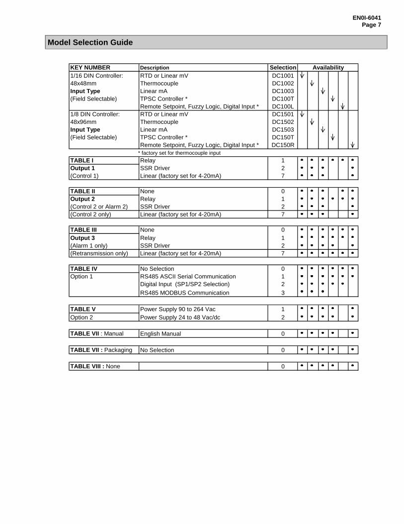
Model Selection Guide
KEY NUMBER Description Selection Availability1/16 DIN Controller: RTD or Linear mV DC100148x48mm Thermocouple DC1002Input Type Linear mA DC1003(Field Selectable) TPSC Controller * DC100T
Remote Setpoint, Fuzzy Logic, Digital Input * DC100L1/8 DIN Controller: RTD or Linear mV DC150148x96mm Thermocouple DC1502Input Type Linear mA DC1503(Field Selectable) TPSC Controller * DC150T
Remote Setpoint, Fuzzy Logic, Digital Input * DC150R * factory set for thermocouple input
TABLE I Relay 1Output 1 SSR Driver 2(Control 1) Linear (factory set for 4-20mA) 7
TABLE II None 0Output 2 Relay 1(Control 2 or Alarm 2) SSR Driver 2(Control 2 only) Linear (factory set for 4-20mA) 7
TABLE III None 0Output 3 Relay 1(Alarm 1 only) SSR Driver 2(Retransmission only) Linear (factory set for 4-20mA) 7
TABLE IV No Selection 0Option 1 RS485 ASCII Serial Communication 1
Digital Input (SP1/SP2 Selection) 2
RS485 MODBUS Communication 3
TABLE V Power Supply 90 to 264 Vac 1Option 2 Power Supply 24 to 48 Vac/dc 2
TABLE VII : Manual English Manual 0
TABLE VII : Packaging No Selection 0
TABLE VIII : None 0

EN0I-6041Page 8
Sensing and ControlHoneywell Inc.11 West Spring StreetFreeport, IL 61032
EN0I-6041 0401 Printed in USA www.honeywell.com/sensing
EXTERNAL DIMENSIONS, PANEL CUTOUT
For more information, contact Honeywell sales at (800) 343-0228. Specifications are subject to change without notice.Distributor:
Warranty/RemedyHoneywell warrants goods of its manufacture as being free of defective materials and faulty workmanship. Contact your local sales office forwarranty information. If warranted goods are returned to Honeywell during the period of coverage, Honeywell will repair or replace withoutcharge those items it finds defective. The foregoing is Buyer’s sole remedy and is in lieu of all other warranties, expressed or implied,including those of merchantability and fitness for a particular purpose. Specifications may change without notice. The information wesupply is believed to be accurate and reliable as of this printing. However, we assume no responsibility for its use.
While we provide application assistance personally, through our literature and the Honeywell web site, it is up to the customer to determinethe suitability of the product in the application.