srd960 universal positioner – all versions - fagerberg · srd960 universal positioner – all...
TRANSCRIPT
Master Instruction 04.2014 MI EVE0109 A-(en)
SRD960 Universal Positioner– All versions –
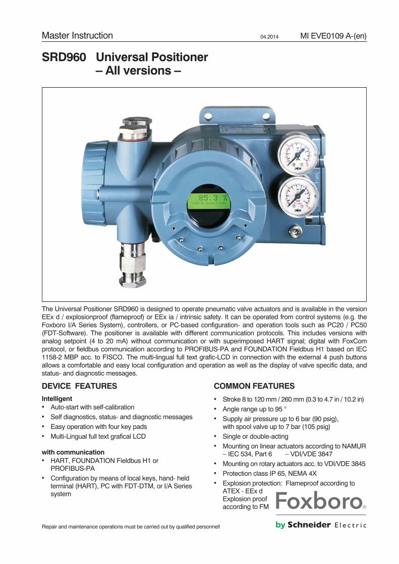
The Universal Positioner SRD960 is designed to operate pneumatic valve actuators and is available in the versionEEx d / explosionproof (flameproof) or EEx ia / intrinsic safety. It can be operated from control systems (e.g. theFoxboro I/A Series System), controllers, or PC-based configuration- and operation tools such as PC20 / PC50(FDT-Software). The positioner is available with different communication protocols. This includes versions withanalog setpoint (4 to 20 mA) without communication or with superimposed HART signal; digital with FoxComprotocol, or fieldbus communication according to PROFIBUS-PA and FOUNDATION Fieldbus H1 based on IEC1158-2 MBP acc. to FISCO. The multi-lingual full text grafic-LCD in connection with the external 4 push buttonsallows a comfortable and easy local configuration and operation as well as the display of valve specific data, andstatus- and diagnostic messages.
DEVICE FEATURES
Intelligent• Auto-start with self-calibration
• Self diagnostics, status- and diagnostic messages
• Easy operation with four key pads
• Multi-Lingual full text grafical LCD
with communication• HART, FOUNDATION Fieldbus H1 or
PROFIBUS-PA
• Configuration by means of local keys, hand- heldterminal (HART), PC with FDT-DTM, or I/A Seriessystem
COMMON FEATURES
• Stroke 8 to 120mm / 260mm (0.3 to 4.7 in / 10.2 in)
• Angle range up to 95 °
• Supply air pressure up to 6 bar (90 psig),with spool valve up to 7 bar (105 psig)
• Single or double-acting
• Mounting on linear actuators according to NAMUR– IEC 534, Part 6 – VDI/VDE 3847
• Mounting on rotary actuators acc. to VDI/VDE 3845
• Protection class IP 65, NEMA 4X
• Explosion protection: Flameproof according toATEX - EEx dExplosion proofaccording to FM
Repair and maintenance operations must be carried out by qualified personnel!
2 SRD960 MI EVE0109 A-(en)
� � � � � � � � � � � � �� � � � � � � � � � � � �� � � � � � � � � � � � � � � � � � � � � � � � � � �
� � � �
� � � � � � � � � � � � � � ! " � � # � � � $ � � � � % � � � � & ' ( & ) � � * + , $ -
� � � . & ) �
/ 0 1
� 2 � � � � � � �
0
3
' 0 ' 3
' ( ' 4
5 � � � � � � � � �5 � � 6 � � � � � � � �
� � � � � � � � � � � � � � 6 � 7 � � 8 � 9 � � � � � � � � � � � � � � � � � � � � � � � � � � ! � � � � � : ; �
� � � � � � � � � � � �� � �
4 � � � 3 ) � 8 � �
� � � � � � � � � �
� � � � 5 � � � � �
� � � � � � � � � � � � � 5 � �� � � � � � � � � � �
� � < � � � � 3 �
� � � � �
� � � � � � , � ! + ; � � 0
� + � � 4 ) = � � � � � > ' ) = � � � � � � �
� 2 � � � � �� � � � � �
�
�
�
��
�
�
� � � � � � � � � � � � �� � � � � � � � � � � � �� � � � � � � � � � � � � � � � � � � � � � � � � � �
� � � �
� � � � � � � � � � � � � � ! " � � # � � � $ � � � � % � � � � & ' ( & ) � � * + , $ -
� � � . & ) �
/ 0 1
� 2 � � � � � � �
0
3
' 0 ' 3
' ( ' 4
5 � � � � � � � � �5 � � 6 � � � � � � � �
� 2 � � � � �� � � � � �
) 0 ) 3
� � � � � � � � � � � �� � �
4 � � � 3 ) � 8 � �
� � � � � � � � � �
� � � � 5 � � � � � �
� � � � � � � � � � � � � 5 � �� � � � � � � � � � �
� � 5 � ) 3 � � � � < � 0 ) ' 4 < � � � 6 � � � � � � & ( .
� 3 � � � � � � 9 � � � � 5 � � � � � � � 4 � � � � &
� � < � � � � 3 �
� � � � �
� � � � � � , � ! + ; � � 0
� � 8 � 9 � ? � 4 3 � � � � � � �
� + � 8 � � � ? � � ( ) = � � � � � � �� + � 8 � 9 � ? � > ' ) = � � � � � � �
� � 8 � 9 � ? � ( 3 � � � �� � � � �
� � �� � � � �
�
� � � � � � � � � � � � � � 6 � 7 � � 8 � 9 � � � � � � � � � � � � � � � � � � � � � � � � � � ! � � � � � : ; �
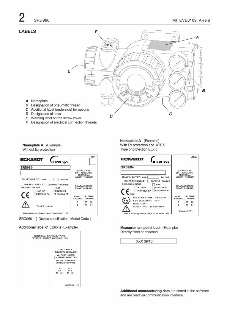
Nameplate A (Example)Without Ex protection
/ 0 1
� � � � � � � � � � � � � � � � � � � � � � � � � �� � � � � � � � � � � � � � � � � � � � � � � � � �
� � � � � 6 � � � � � � � � � � � � � � � � � �
� � � � � @ � �/ � � � � � � � � � � � 1
� � � � � 0� � � � � 04 0 � � � � 4 3
� � � � 3� � � � 3A 0 � � � � A 3
� � � � � � � � � � � � � � � � � �/ � � � � � � � � � � � � � 1
A A & B 3 . 0 ) '
Nameplate A (Example)With Ex protection acc. ATEXType of protection EEx d
LABELS
A NameplateB Designation of pneumatic threadC Additional label (underside) for optionsD Designation of keysE Warning label on the screw coverF Designation of electrical connection threads
SRD960- [ Device specification, Model Code ]
Additional label C Options (Example) Measurement point label (Example)Directly fixed or attached
XXX 09/16
Additional manufacturing data are stored in the softwareand are read via communication interface.
MI EVE0109 A-(en) SRD960 3TABLE OF CONTENTS
CHAP: CONTENT PAGE
LABELS . . . . . . . . . . . . . . . . . . . . . . . . . . 2
0 SUMMARY
HART . . . . . . . . . . . . . . . . . . . . . . . . . . . . 4
FOUNDATION Fieldbus Communikation . . 5
PROFIBUS Communication . . . . . . . . . . . . 6
1 METHOD OF OPERATION . . . . . . . . . . . . 8
1.1 General . . . . . . . . . . . . . . . . . . . . . . . . . . . 8
1.2 Block diagram . . . . . . . . . . . . . . . . . . . . . . 8
1.3 Functional description. . . . . . . . . . . . . . . . . 8
2 OPERATION MODES . . . . . . . . . . . . . . . . 9
3 DESIGN - FUNCTIONALDESIGNATIONS 10
3.1 Pneumatic accessories. . . . . . . . . . . . . . . 11
4 MOUNTING TO ACTUATORS . . . . . . . . 12
4.1 Linear, NAMUR Mounting (left hand) . . . . 14
4.2 Linear, NAMUR Mounting (right hand) . . . 16
4.3 Linear, Direct Mounting . . . . . . . . . . . . . . 18
4.4 Rotary actuators. . . . . . . . . . . . . . . . . . . . 20
5 PNEUMATIC CONNECTIONS. . . . . . . . . 22
6 ELECTRICAL CONNECTION . . . . . . . . . 23
7 OPTIONS . . . . . . . . . . . . . . . . . . . . . . . . 24
7.1 “Limit switch” . . . . . . . . . . . . . . . . . . . . . . 24
7.2 “Additional In-/Outputs”. . . . . . . . . . . . . . . 25
7.3 “Built-in pressure sensors” . . . . . . . . . . . . 25
CHAP: CONTENT PAGE
8 START-UP . . . . . . . . . . . . . . . . . . . . . . . 26
8.1 General . . . . . . . . . . . . . . . . . . . . . . . . . . 26
Setting by means of local keys . . . . . . . . 26
8.2 Operation. . . . . . . . . . . . . . . . . . . . . . . . . 27
Operation with local keys . . . . . . . . . . . . 28
Table: Menu structure. . . . . . . . . . . . . . . 29
8.3 Description of menus . . . . . . . . . . . . . . . 31
9 DECOMMISSIONING . . . . . . . . . . . . . . . 46
10 MAINTENANCE . . . . . . . . . . . . . . . . . . . 47
10.1 Service connector and IrCom . . . . . . . . . . 47
10.2 Supply filter replacement . . . . . . . . . . . . . 47
10.3 Pneumatic amplifier . . . . . . . . . . . . . . . . . 47
10.4 Replacement of mechanical andpneumatic units:
Removal of electronics unit . . . . . . . . . . . 48
Option “Built-in pressure sensors”. . . . . . . 49
Option “Additional In-/Outputs” . . . . . . . . . 50
Option “Limit switch”. . . . . . . . . . . . . . . . . 51
10.5 Angle calibration. . . . . . . . . . . . . . . . . . . . 52
11 TROUBLE-SHOOTING GUIDE . . . . . . . . 53
12 SAFETY REQUIREMENTS . . . . . . . . . . . 58
13 SYSTEM CONFIGURATION . . . . . . . . . . 58
DIMENSIONS . . . . . . . . . . . . . . . . . . . . . 62
Installation and start-up of instrument to be carried out only by qualified personnel, familiar with installation andstart-up procedures and operation of this product!Accident preventionThe connected instrument contains mechanically movingparts, e.g. feedback lever, which could cause injuries.The operators have to be instructed accordingly.
and connected in accordance with ist connection diagram(see page 60).Locally applicable installation regulations for electricalequipment must be observed, e.g. in the Federal Republicof Germany DIN VDE 0100 resp. DIN VDE 0800.The instrument must be operated with safety extra low vol-tage SELV or SELV-E.Safety precautions taken in the instrument may be render-ed ineffectual if the instrument is not operated in accord-ance with the Master Instructions.Limitation of power supplies for fire protection must be ob-served due to EN 61010-1, appendix F or IEC 1010-1.
Electrical safetyThis instrument satisfies the conditions for safety class III,overvoltage category I according to EN 61010-1 orIEC1010-1.Any work on electrical parts must be done by qualifiedpersonnel if any supply is connected to the instrument.The instrument must be used for ist designated purpose
4 SRD960 MI EVE0109 A-(en)
� � � � � � � � � � � � �
� � � � � � � � �
� � � � � � � � � �
� � �� � �
� � �
� � � � �
� � � � � �
� � � � � � � � �� � � � � �
� � �
� � � � � � � � � � � � � � � � � � � � � � �
� � ! � " � � � � � � � � � � �# $ � � � � � � " � � � ! � % � � �� & " & � ' � � � ' ( � ) * � + ,
� � � � � � � � �� � � � � � � �
- � . � / / 0 � � � 1 � � � � � �
- � 2 � � � � � � � � � 3 � � � �% � � � � * 4 � � ( � � � � 5% � � � � - * � � � � ! � % � � �
) + � 5 ,
6 � � � � � � � � � + � � � � � � �6 6 + � � �
� � � � � � � � �� � � � � � � �
/ / 0 � � � � � * � � � � $ � � � ! - � � � & � � ! � � � � � / / 0 � �
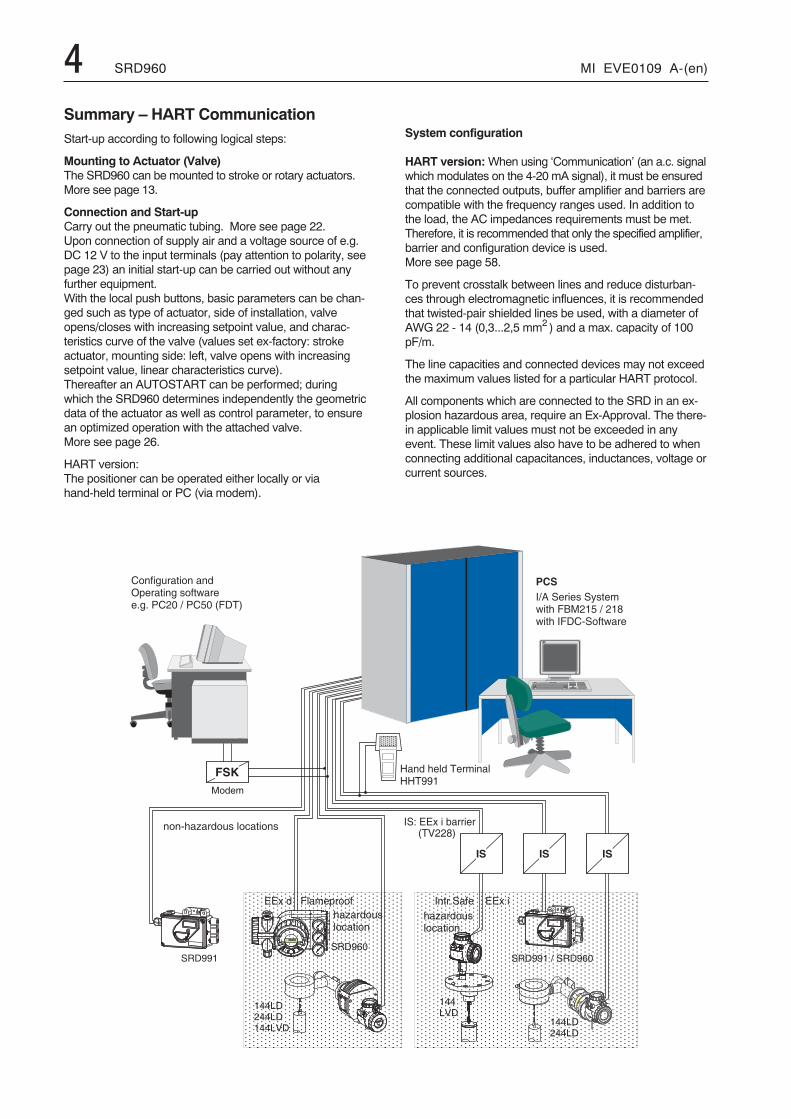
Summary – HART CommunicationStart-up according to following logical steps:
Mounting to Actuator (Valve)The SRD960 can be mounted to stroke or rotary actuators.More see page 13.
Connection and Start-upCarry out the pneumatic tubing. More see page 22.Upon connection of supply air and a voltage source of e.g.DC 12 V to the input terminals (pay attention to polarity, seepage 23) an initial start-up can be carried out without anyfurther equipment.With the local push buttons, basic parameters can be chan-ged such as type of actuator, side of installation, valveopens/closes with increasing setpoint value, and charac-teristics curve of the valve (values set ex-factory: strokeactuator, mounting side: left, valve opens with increasingsetpoint value, linear characteristics curve).Thereafter an AUTOSTART can be performed; duringwhich the SRD960 determines independently the geometricdata of the actuator as well as control parameter, to ensurean optimized operation with the attached valve.More see page 26.
HART version:The positioner can be operated either locally or viahand-held terminal or PC (via modem).
System configuration
HART version:When using ‘Communication’ (an a.c. signalwhich modulates on the 4-20 mA signal), it must be ensuredthat the connected outputs, buffer amplifier and barriers arecompatible with the frequency ranges used. In addition tothe load, the AC impedances requirements must be met.Therefore, it is recommended that only the specified amplifier,barrier and configuration device is used.More see page 58.
To prevent crosstalk between lines and reduce disturban-ces through electromagnetic influences, it is recommendedthat twisted-pair shielded lines be used, with a diameter ofAWG 22 - 14 (0,3...2,5 mm2 ) and a max. capacity of 100pF/m.
The line capacities and connected devices may not exceedthe maximum values listed for a particular HART protocol.
All components which are connected to the SRD in an ex-plosion hazardous area, require an Ex-Approval. The there-in applicable limit values must not be exceeded in anyevent. These limit values also have to be adhered to whenconnecting additional capacitances, inductances, voltage orcurrent sources.
MI EVE0109 A-(en) SRD960 5
� � � � � � � � � � � � � � �
+ � �
� �
+
� � � � � �� � � �
� � " � � � � � �� � " � � � � �
+
� �
� � $ � � � � �
+ +
+
� � � � � � � � �
� � � � � � � � �
� � � �
� � � �
� � � � � �
� � �� � �
� � �
+ . � 4 � � � � � � � � � � � � �
� � � � � � � � � � � � �� � � � � � � � � � � � � �
' � 1 � � � � � � � � ' � - 2 � � � � � �! � � � � 7 � � � � � � � � - � � � � � � � � � �
� � � � � � � � � � � � � � � � �� � � � � � � � � � � � � � � � � �
� � � � � � � � � � � � � � � � � � � � / / 0 � �
� �
' & � & . � ' � % � � � � � $ $ � 3
� � � � � � � � � �� � � � � � � � � / / 0 � �
- � . � / 0 � 1 � � � � � �
� �
� & " & � - 2 � � � ' ( � ) * � + ,
� & " & � - � 2 � � � � � � � � � 3 � � � �% � � � � * 4 � � � � * 4 � �
� � � � � � � � � � � � �� � � � � � � � �� � � / / 0 � �
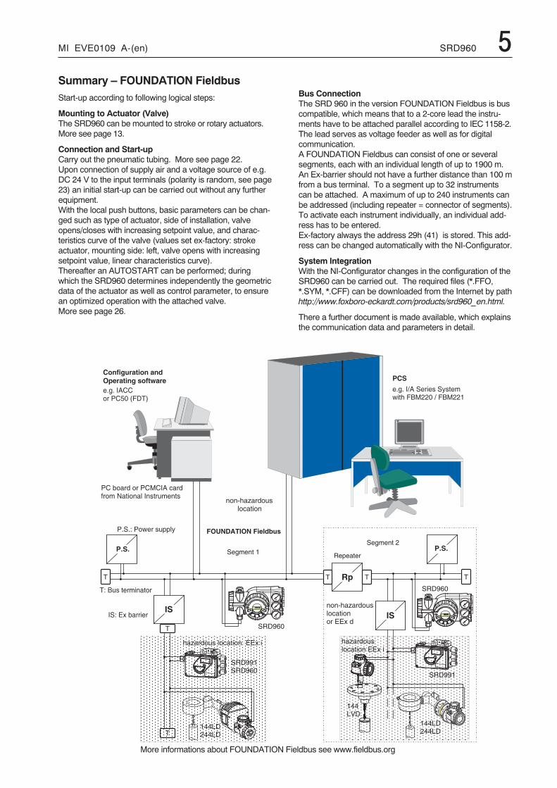
Summary – FOUNDATION FieldbusStart-up according to following logical steps:
Mounting to Actuator (Valve)The SRD960 can be mounted to stroke or rotary actuators.More see page 13.
Connection and Start-upCarry out the pneumatic tubing. More see page 22.Upon connection of supply air and a voltage source of e.g.DC 24 V to the input terminals (polarity is random, see page23) an initial start-up can be carried out without any furtherequipment.With the local push buttons, basic parameters can be chan-ged such as type of actuator, side of installation, valveopens/closes with increasing setpoint value, and charac-teristics curve of the valve (values set ex-factory: strokeactuator, mounting side: left, valve opens with increasingsetpoint value, linear characteristics curve).Thereafter an AUTOSTART can be performed; duringwhich the SRD960 determines independently the geometricdata of the actuator as well as control parameter, to ensurean optimized operation with the attached valve.More see page 26.
Bus ConnectionThe SRD 960 in the version FOUNDATION Fieldbus is buscompatible, which means that to a 2-core lead the instru-ments have to be attached parallel according to IEC 1158-2.The lead serves as voltage feeder as well as for digitalcommunication.A FOUNDATION Fieldbus can consist of one or severalsegments, each with an individual length of up to 1900 m.An Ex-barrier should not have a further distance than 100 mfrom a bus terminal. To a segment up to 32 instrumentscan be attached. A maximum of up to 240 instruments canbe addressed (including repeater = connector of segments).To activate each instrument individually, an individual add-ress has to be entered.Ex-factory always the address 29h (41) is stored. This add-ress can be changed automatically with the NI-Configurator.
System IntegrationWith the NI-Configurator changes in the configuration of theSRD960 can be carried out. The required files (*.FFO,*.SYM, *.CFF) can be downloaded from the Internet by pathhttp://www.foxboro-eckardt.com/products/srd960_en.html.
There a further document is made available, which explainsthe communication data and parameters in detail.
More informations about FOUNDATION Fieldbus see www.fieldbus.org
6 SRD960 MI EVE0109 A-(en)
' � # * - 4 8 � � ' 2
� � � � � � � � � � � � � � �
+
+
� '
' 2
' � # * - 4 8 � � � '
) � � � 9 � ,
) � � � 9 � ,
' � # * - 4 8 � � ' 2
+
� '
' 2+
� � � �� � � � �
) � � � 9 � ,
� � � � ) � � � 9 � ,
� � � � � �) � � � 9 � ,
) � � � 9 � ,� � � � � �
+/ / 0 � �
' �) � � � � � � � � � � � � � ,
+ . � 4 � � � � � � � � � � � � �� � � � � � � � � � � � � � � � � � � � � �� � � / / 0 � � �
� � : � ' � 1 � � � � � � �' � - 2 � � � � � � ! � � � � � � ! � � � ") � � � � � � � � � � � � ,
� � ! � " � � � � � � � � � � �# $ � � � � � � " � � � ! � % � � �) � � � � � � � � � � � � ,� & " & � ' � �' ( � ) * � + ,
� � " � � � �� � � $ � � �
) � � � % � . � / 09 � � � � � � ,
/ / 0 � � � � � � � � � � � � � � � � � � � � � �
� � " � � � �� � � $ � � �
' & � & . � ' � % � � � � � $ $ � 3
' & � &
' & � &
� & " & � - � 2 � � � � � � � � � 3 � � � �% � � � � * 4 � :
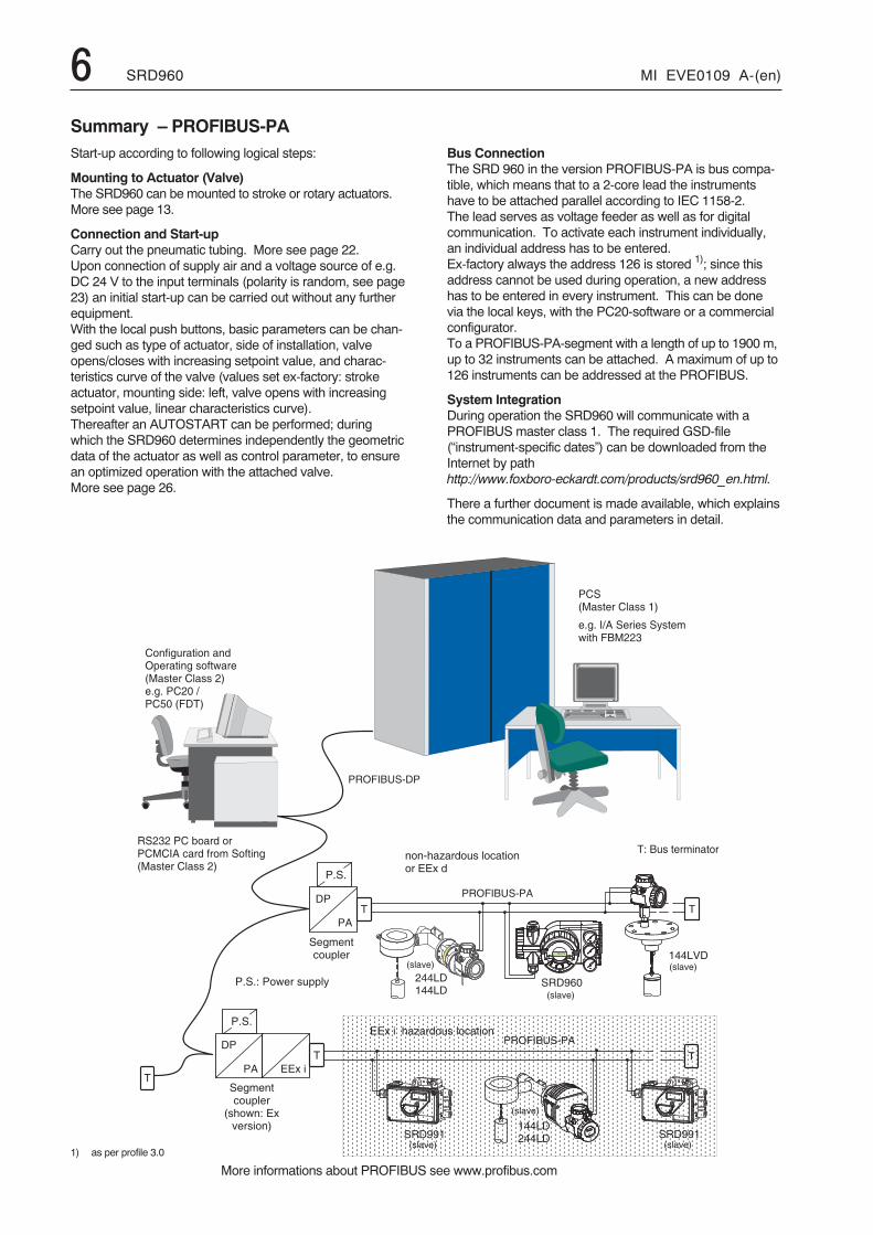
Summary – PROFIBUS-PAStart-up according to following logical steps:
Mounting to Actuator (Valve)The SRD960 can be mounted to stroke or rotary actuators.More see page 13.
Connection and Start-upCarry out the pneumatic tubing. More see page 22.Upon connection of supply air and a voltage source of e.g.DC 24 V to the input terminals (polarity is random, see page23) an initial start-up can be carried out without any furtherequipment.With the local push buttons, basic parameters can be chan-ged such as type of actuator, side of installation, valveopens/closes with increasing setpoint value, and charac-teristics curve of the valve (values set ex-factory: strokeactuator, mounting side: left, valve opens with increasingsetpoint value, linear characteristics curve).Thereafter an AUTOSTART can be performed; duringwhich the SRD960 determines independently the geometricdata of the actuator as well as control parameter, to ensurean optimized operation with the attached valve.More see page 26.
1) as per profile 3.0
Bus ConnectionThe SRD 960 in the version PROFIBUS-PA is bus compa-tible, which means that to a 2-core lead the instrumentshave to be attached parallel according to IEC 1158-2.The lead serves as voltage feeder as well as for digitalcommunication. To activate each instrument individually,an individual address has to be entered.Ex-factory always the address 126 is stored 1); since thisaddress cannot be used during operation, a new addresshas to be entered in every instrument. This can be donevia the local keys, with the PC20-software or a commercialconfigurator.To a PROFIBUS-PA-segment with a length of up to 1900 m,up to 32 instruments can be attached. A maximum of up to126 instruments can be addressed at the PROFIBUS.
System IntegrationDuring operation the SRD960 will communicate with aPROFIBUS master class 1. The required GSD-file(“instrument-specific dates”) can be downloaded from theInternet by pathhttp://www.foxboro-eckardt.com/products/srd960_en.html.
There a further document is made available, which explainsthe communication data and parameters in detail.
More informations about PROFIBUS see www.profibus.com
MI EVE0109 A-(en) SRD960 7
� � � �
� � � � �
� � � � � �� � � � � �
� � �� � �
� � ! "
� � � � �
� � � � � �
� � � � �� � � � � �
� � �
� � � � � � � � � � � � � �� � � � � � � �
� � ! � " � � � � � � � � � � �# $ � � � � � � " � � � ! � % � � �� & " & � ' � � � ' ( � ) * � + ,
� � � � � � � � �� � � � � � � � � � � � �� � � � � � � / / 0 � �
� � � � � � � � � �� � � � � � � �/ / 0 � �
- � . � / / 0 � � � 1 � � � � � �
- � 2 � � � � � � � � � 3 � � � �% � � � � * 4 � � : � � � � : � � � � % � � � � - * � � � � ! � % � � �
) � + 5 ,
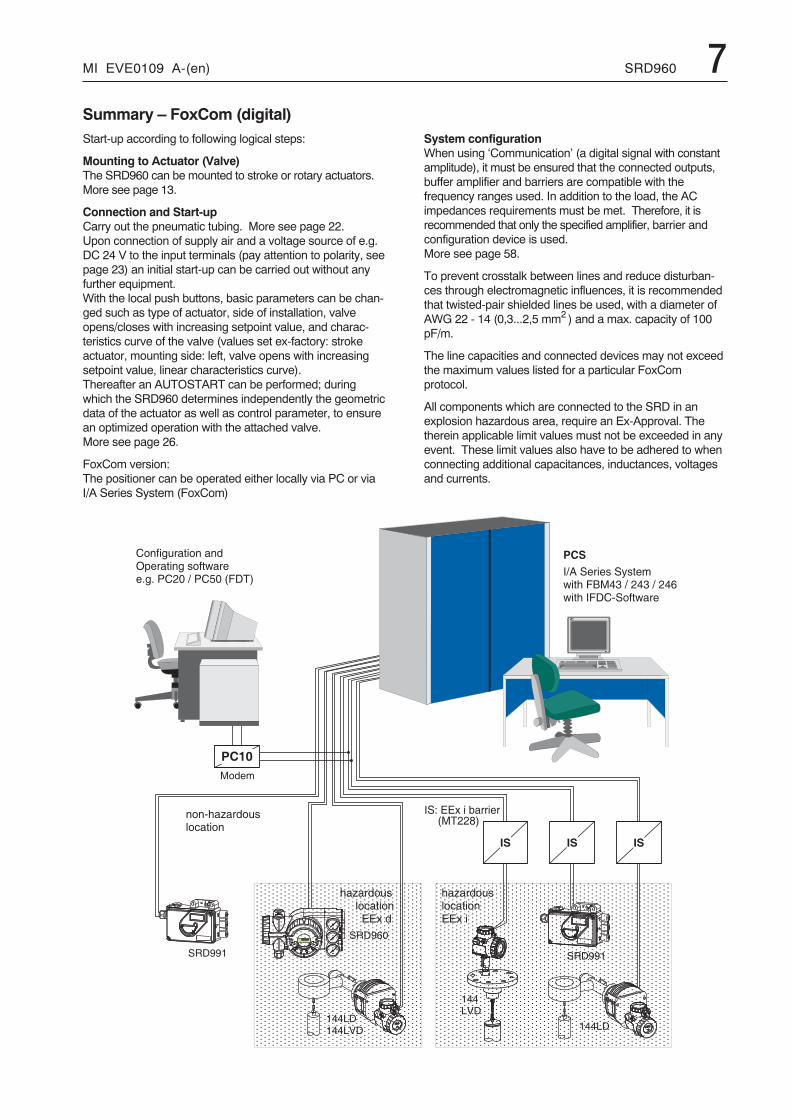
Summary – FoxCom (digital)Start-up according to following logical steps:
Mounting to Actuator (Valve)The SRD960 can be mounted to stroke or rotary actuators.More see page 13.
Connection and Start-upCarry out the pneumatic tubing. More see page 22.Upon connection of supply air and a voltage source of e.g.DC 24 V to the input terminals (pay attention to polarity, seepage 23) an initial start-up can be carried out without anyfurther equipment.With the local push buttons, basic parameters can be chan-ged such as type of actuator, side of installation, valveopens/closes with increasing setpoint value, and charac-teristics curve of the valve (values set ex-factory: strokeactuator, mounting side: left, valve opens with increasingsetpoint value, linear characteristics curve).Thereafter an AUTOSTART can be performed; duringwhich the SRD960 determines independently the geometricdata of the actuator as well as control parameter, to ensurean optimized operation with the attached valve.More see page 26.
FoxCom version:The positioner can be operated either locally via PC or viaI/A Series System (FoxCom)
System configurationWhen using ‘Communication’ (a digital signal with constantamplitude), it must be ensured that the connected outputs,buffer amplifier and barriers are compatible with thefrequency ranges used. In addition to the load, the ACimpedances requirements must be met. Therefore, it isrecommended that only the specified amplifier, barrier andconfiguration device is used.More see page 58.
To prevent crosstalk between lines and reduce disturban-ces through electromagnetic influences, it is recommendedthat twisted-pair shielded lines be used, with a diameter ofAWG 22 - 14 (0,3...2,5 mm2 ) and a max. capacity of 100pF/m.
The line capacities and connected devices may not exceedthe maximum values listed for a particular FoxComprotocol.
All components which are connected to the SRD in anexplosion hazardous area, require an Ex-Approval. Thetherein applicable limit values must not be exceeded in anyevent. These limit values also have to be adhered to whenconnecting additional capacitances, inductances, voltagesand currents.
8 SRD960 MI EVE0109 A-(en)
�
� �
� �
�
�
�
� � � � � � �
�
� �
� �
� �
�
�
� � � � � &
� �
�
�
���
�
�
�
�
�
� �
� �
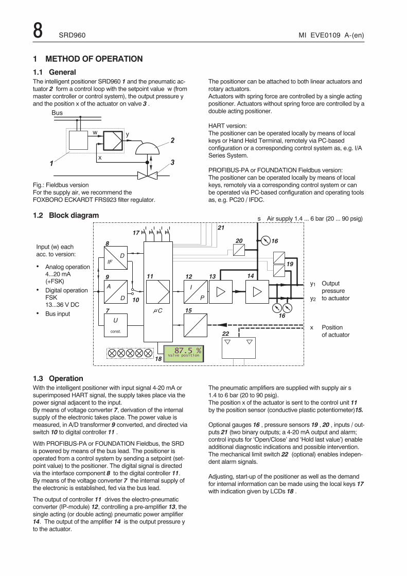
x Positionof actuator
y1 Outputpressure
y2 to actuator
Input (w) eachacc. to version:
• Analog operation4...20 mA(+FSK)
• Digital operationFSK13...36 V DC
• Bus input
s Air supply 1.4 ... 6 bar (20 ... 90 psig)
1.3 OperationWith the intelligent positioner with input signal 4-20 mA orsuperimposed HART signal, the supply takes place via thepower signal adjacent to the input.By means of voltage converter 7, derivation of the internalsupply of the electronic takes place. The power value ismeasured, in A/D transformer 9 converted, and directed viaswitch 10 to digital controller 11 .
With PROFIBUS-PA or FOUNDATION Fieldbus, the SRDis powered by means of the bus lead. The positioner isoperated from a control system by sending a setpoint (set-point value) to the positioner. The digital signal is directedvia the interface component 8 to the digital controller 11.By means of the voltage converter 7 the internal supply ofthe electronic is established, fed via the bus lead.
The output of controller 11 drives the electro-pneumaticconverter (IP-module) 12, controlling a pre-amplifier 13, thesingle acting (or double acting) pneumatic power amplifier14. The output of the amplifier 14 is the output pressure yto the actuator.
The pneumatic amplifiers are supplied with supply air s1.4 to 6 bar (20 to 90 psig).The position x of the actuator is sent to the control unit 11by the position sensor (conductive plastic potentiometer)15.
Optional gauges 16 , pressure sensors 19 , 20 , inputs / out-puts 21 (two binary outputs; a 4-20 mA output and alarm;control inputs for ‘Open/Close’ and ‘Hold last value’) enableadditional diagnostic indications and possible intervention.The mechanical limit switch 22 (optional) enables indepen-dent alarm signals.
Adjusting, start-up of the positioner as well as the demandfor internal information can be made using the local keys 17with indication given by LCDs 18 .
1 METHOD OF OPERATION
1.1 GeneralThe intelligent positioner SRD960 1 and the pneumatic ac-tuator 2 form a control loop with the setpoint value w (frommaster controller or control system), the output pressure yand the position x of the actuator on valve 3 .
Fig.: Fieldbus versionFor the supply air, we recommend theFOXBORO ECKARDT FRS923 filter regulator.
1.2 Block diagram
The positioner can be attached to both linear actuators androtary actuators.Actuators with spring force are controlled by a single actingpositioner. Actuators without spring force are controlled by adouble acting positioner.
HART version:The positioner can be operated locally by means of localkeys or Hand Held Terminal, remotely via PC-basedconfiguration or a corresponding control system as, e.g. I/ASeries System.
PROFIBUS-PA or FOUNDATION Fieldbus version:The positioner can be operated locally by means of localkeys, remotely via a corresponding control system or canbe operated via PC-based configuration and operating toolsas, e.g. PC20 / IFDC.
MI EVE0109 A-(en) SRD960 92 OPERATING MODESOperation of the positioner is divided into individual ‘opera-ting modes’. Operating modes may change depending on,for example, key commands or internal calculations.The different operating modes are described in abbreviatedform below.
INITIALIZE:Upon power-up or Reset (pressing of keys (�) (–) (+) simul-taneously), several self-tests are conducted. Individual stepsin the self-test process are indicated by the LCD.
If no error occurs the device moves to OUT OF SERVICE,if it is still in a delivery condition; AUTOSTART has to beperformed. If AUTOSTART was done already, the devicewill go to IN OPERATION.
If faults are detected, the code of the faulty self-test willremain (see page 53). If error reoccurs after reset, thedevice is probably defect and should be sent in for repair.
DEVICE FAULT:In the event that the LCD shows a message, a device faultis signaled. These faults are detected during cyclical self-test.The device can no longer be operated. This could be cau-sed a. o. by a jammed menu key, defect program memory,etc. (see chapter “Trouble-shooting”).This condition disappears through new resetting until thesame error is detected again. If a device error occurs re-peatedly, the device should be sent in for repair.
IN OPERATION:After performing an AUTOSTART, the device moves toIN OPERATION and will always, even after restarting or re-setting, move back to the safety position (de-energizedvalve position) or FAILSAFE. If setpoint values are fed viacommunication, the SRD will go to IN OPERATION.
FAILSAFE:Positioner carries out actions as configured in menu “failurehandling”. Additionally, the cyclical self-diagnosis takesplace.If the instrument is IN OPERATION, but no setpoint valuesarrive via communication, the SRD will go to FAILSAFEmode, after a defined time period; either with– maintaining last value– output pressureless, or– with predetermined position.As soon as setpoint values arrive via communication again,the instrument is immediately back IN OPERATION.
OUT OF SERVICE:The SRD960 in ist delivery condition is configured in such away that it will remain OUT OF SERVICE after power-upuntil moving to IN OPERATION via the manually initiatedfunction AUTOSTART.In the device state OUT OF SERVICE the menu enteringmode remains active at all times. If a device has been INOPERATION already and is removed from an actuator andmounted to another, it is recommended to take the deviceout of operation via RESET CONFIG (Menu 9.1) prior todisconnecting the device from the first actuator.This enables the next actuator to be started in the deliverycondition (see chapter 8).
CALIBRATE:During an AUTOSTART function the device is in conditionCALIBRATION. The actuator is moved up- and downwardsseveral times, and the device could be busy for a longerperiod of time. Subsequently, the device moves to INOPERATION.
MESSAGE:The SRD960 continuously supervises ist important devicefunctions. In the event that limit values are exceeded oroperational problems occur, messages are signaled via theLCD.The message with the highest priority will be indicated first.With key (–) additional messages can be called up, withkey (+) the measuring values can be retrieved. It is possibleat all times to reach the menu by pressing the menu keys topossibly eliminate the problem by performing suitable menufunctions. Further references may be found in chapter“Trouble-shooting”.
SIMULATE (FOUNDATION FIELDBUS version only)During function IN OPERATION, the valve position queriedvia the communication, can be simulated with a value thathas been entered via communication into the instrumentduring position SIMULATION. Thereby the positionercontinues with normal operation and regulates to the”accurate” set value.For the SRD , this function has to be additionally released orblocked via menu 10.
LCD description and possible operator interventions aredescribed in chapter: START-UP.
10 SRD960 MI EVE0109 A-(en)
�
�
� �
�
�
�
�
�
� � �
�
� � �� � � � � �
� � �
� � �
� �
� �
�
�
� �
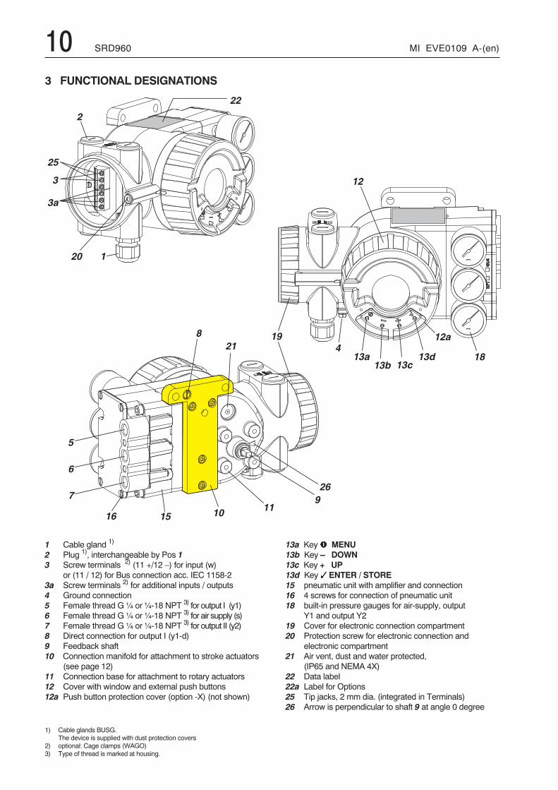
1 Cable gland 1)
2 Plug 1), interchangeable by Pos 13 Screw terminals 2) (11 +/12 –) for input (w)
or (11 / 12) for Bus connection acc. IEC 1158-23a Screw terminals 2) for additional inputs / outputs4 Ground connection5 Female thread G ¼ or ¼-18 NPT 3) for output I (y1)6 Female thread G ¼ or ¼-18 NPT 3) for air supply (s)7 Female thread G ¼ or ¼-18 NPT 3) for output II (y2)8 Direct connection for output I (y1-d)9 Feedback shaft10 Connection manifold for attachment to stroke actuators
(see page 12)11 Connection base for attachment to rotary actuators12 Cover with window and external push buttons12a Push button protection cover (option -X) (not shown)
1) Cable glands BUSG.The device is supplied with dust protection covers
2) optional: Cage clamps (WAGO)3) Type of thread is marked at housing.
13a Key� MENU13b Key – DOWN13c Key + UP13d Key � ENTER / STORE15 pneumatic unit with amplifier and connection16 4 screws for connection of pneumatic unit18 built-in pressure gauges for air-supply, output
Y1 and output Y219 Cover for electronic connection compartment20 Protection screw for electronic connection and
electronic compartment21 Air vent, dust and water protected,
(IP65 and NEMA 4X)22 Data label22a Label for Options25 Tip jacks, 2 mm dia. (integrated in Terminals)26 Arrow is perpendicular to shaft 9 at angle 0 degree
3 FUNCTIONAL DESIGNATIONS
MI EVE0109 A-(en) SRD960 11
� � �� � � � � � � � �
� �
� �
� � �� � � �
� � � � � �
� � � �
� �
� � � � � � � � �
� � � � � � � �
� � � � �
� � � � � � � �
� � � � � � � �
� � � � � � � �
� � � �
�� � � �
� � �� � � � � � � � �
� � � � � � � � � � � � � � �
� � � � � � � � � � � ! �
� � � � � � � � � � � � � �
* � � � � � < � � � � � / � � 0 � C * � � � � 0 � 4 1� � � � � � � " � � � # � $ % � �& ' � ( ) * � + � ( � ( � ) � �
, � � � � � � � - � .
* � � � � � < � � � 2/ � ) ) � ' � ( � ) � & ) ( " � % # �
� ( � 0 � � � � � � � 0 � � & #
, � � � � � � � - � .
1 � 0 & � � ) � ( �� ( % � ) ' � �
,
�
-
, � � � � � � � - � .
� 5 � 3 ) 0� � � � � � � " � � � ( ) * % � � & ' � ( ) * � + � ( � ( � ) � � �� ( � 0 � 0 ( * 0 � � � + � � ' & + & ' ( � �
� / ; < � ; �
� / ; < � = �
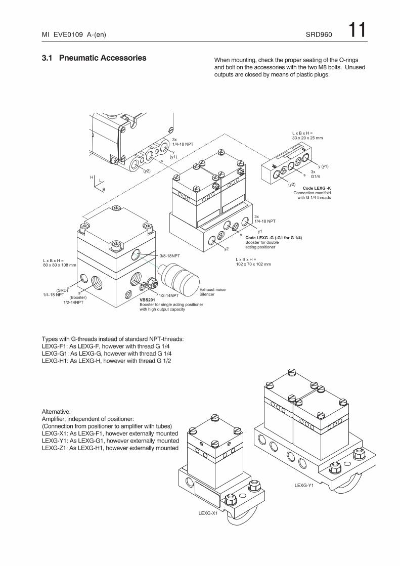
3.1 Pneumatic Accessories
Types with G-threads instead of standard NPT-threads:LEXG-F1: As LEXG-F, however with thread G 1/4LEXG-G1: As LEXG-G, however with thread G 1/4LEXG-H1: As LEXG-H, however with thread G 1/2
Alternative:Amplifier, independent of positioner:(Connection from positioner to amplifier with tubes)LEXG-X1: As LEXG-F1, however externally mountedLEXG-Y1: As LEXG-G1, however externally mountedLEXG-Z1: As LEXG-H1, however externally mounted
When mounting, check the proper seating of the O-ringsand bolt on the accessories with the two M8 bolts. Unusedoutputs are closed by means of plastic plugs.
12 SRD960 MI EVE0109 A-(en)
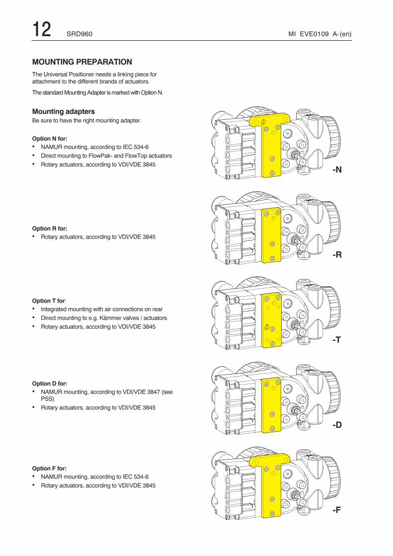
MOUNTING PREPARATIONThe Universal Positioner needs a linking piece forattachment to the different brands of actuators.
The standardMountingAdapter ismarkedwithOptionN.
Mounting adaptersBe sure to have the right mounting adapter.
Option N for:• NAMUR mounting, according to IEC 534-6
• Direct mounting to FlowPak- and FlowTop actuators
• Rotary actuators, according to VDI/VDE 3845
Option R for:• Rotary actuators, according to VDI/VDE 3845
Option T for:• Integrated mounting with air connections on rear
• Direct mounting to e.g. Kämmer valves / actuators
• Rotary actuators, according to VDI/VDE 3845
Option D for:• NAMUR mounting, according to VDI/VDE 3847 (see
PSS)
• Rotary actuators, according to VDI/VDE 3845
Option F for:• NAMUR mounting, according to IEC 534-6
• Rotary actuators, according to VDI/VDE 3845
#
# �
#
# �
# �
MI EVE0109 A-(en) SRD960 13
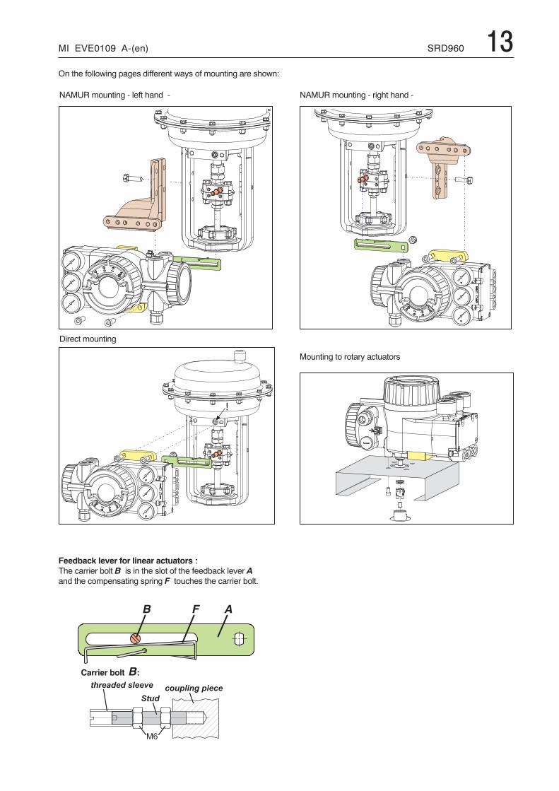
Direct mounting
�� �
Feedback lever for linear actuators �
The carrier bolt B is in the slot of the feedback lever Aand the compensating spring F touches the carrier bolt.
Carrier bolt B:
2 3
� � � � � � � � � �� � � � � � � � � � � � �
� � � �
NAMUR mounting - left hand - NAMUR mounting - right hand -
On the following pages different ways of mounting are shown:
Mounting to rotary actuators
14 SRD960 MI EVE0109 A-(en)
�
�
�� 5
� � �
�
�� �
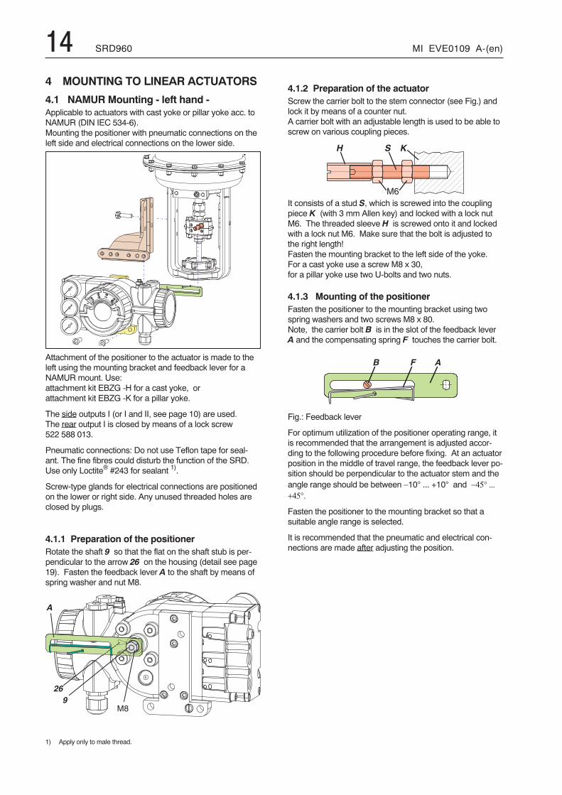
4 MOUNTING TO LINEAR ACTUATORS
4.1 NAMUR Mounting - left hand -Applicable to actuators with cast yoke or pillar yoke acc. toNAMUR (DIN IEC 534-6).Mounting the positioner with pneumatic connections on theleft side and electrical connections on the lower side.
Attachment of the positioner to the actuator is made to theleft using the mounting bracket and feedback lever for aNAMUR mount. Use:attachment kit EBZG -H for a cast yoke, orattachment kit EBZG -K for a pillar yoke.
The side outputs I (or I and II, see page 10) are used.The rear output I is closed by means of a lock screw522 588 013.
Pneumatic connections: Do not use Teflon tape for seal-ant. The fine fibres could disturb the function of the SRD.Use only Loctite® #243 for sealant 1).
Screw-type glands for electrical connections are positionedon the lower or right side. Any unused threaded holes areclosed by plugs.
4.1.1 Preparation of the positionerRotate the shaft 9 so that the flat on the shaft stub is per-pendicular to the arrow 26 on the housing (detail see page19). Fasten the feedback lever A to the shaft by means ofspring washer and nut M8.
1) Apply only to male thread.
4.1.2 Preparation of the actuatorScrew the carrier bolt to the stem connector (see Fig.) andlock it by means of a counter nut.A carrier bolt with an adjustable length is used to be able toscrew on various coupling pieces.
It consists of a stud S, which is screwed into the couplingpiece K (with 3 mm Allen key) and locked with a lock nutM6. The threaded sleeve H is screwed onto it and lockedwith a lock nut M6. Make sure that the bolt is adjusted tothe right length!Fasten the mounting bracket to the left side of the yoke.For a cast yoke use a screw M8 x 30,for a pillar yoke use two U-bolts and two nuts.
4.1.3 Mounting of the positionerFasten the positioner to the mounting bracket using twospring washers and two screws M8 x 80.Note, the carrier bolt B is in the slot of the feedback leverA and the compensating spring F touches the carrier bolt.
Fig.: Feedback lever
For optimum utilization of the positioner operating range, itis recommended that the arrangement is adjusted accor-ding to the following procedure before fixing. At an actuatorposition in the middle of travel range, the feedback lever po-sition should be perpendicular to the actuator stem and theangle range should be between −10° ... +10° and −45° ...+45°.
Fasten the positioner to the mounting bracket so that asuitable angle range is selected.
It is recommended that the pneumatic and electrical con-nections are made after adjusting the position.
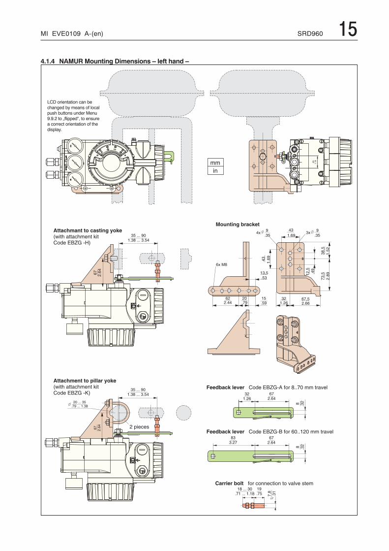
MI EVE0109 A-(en) SRD960 154.1.4 NAMUR Mounting Dimensions – left hand –
� �� �
����
����
>:?(
&5�
�&(
:5?(
� :� & �
� ?(
&��
> ? (:
& : (: 0 �
& & � �
& > � � &
� 0& : (�
�:�&�
0 � � 5
� : ? (& ( :
� (& ( �
>?5
&:�
� �& > (
� 5 � & & & � : & > � � & & & � � & � 5
5 &:
> & �
: � &
5 :: & >
> & �
5 &:
> &�
: ( � & & & � � � & : 5 � & & & � : & ( �
> &�
: ( � & & & � � � & : 5 � & & & � : & ( �
� & & & � : (& > � � & & & � � & : 5
� � � � � � $ % � � � & � � � � � � � � � / 4 @ < � 2 � ! � � � 5 & & > � � � � � � � 9 � �
� � � � � � $ % � � � & � � � � � � � � � / 4 @ < � 4 � ! � � � & & � � � � � � � � 9 � �
� � � � � � � � � � � � � � � ! � � � � � � � � � � � � � � � � � 9 � � 9 � � � � � �
' � � � � � � � � � � � $ % � �
� $ � � � � �
� � � � $ ( ) � � � � � � � $ � � � � � � � * � % �) % � � � � � � � � � � � � � � � A � � � � � � � / 4 @ < � � 6 ,
� � � � $ ( ) � � � � � � � � � � � � � � * � % �) % � � � � � � � � � � � � � � � A � � � � � � � / 4 @ < � � B ,
LCD orientation can bechanged by means of localpush buttons under Menu9.9.2 to „flipped“, to ensurea correct orientation of thedisplay.
16 SRD960 MI EVE0109 A-(en)
�� 5 � �
�
��
� � �
�
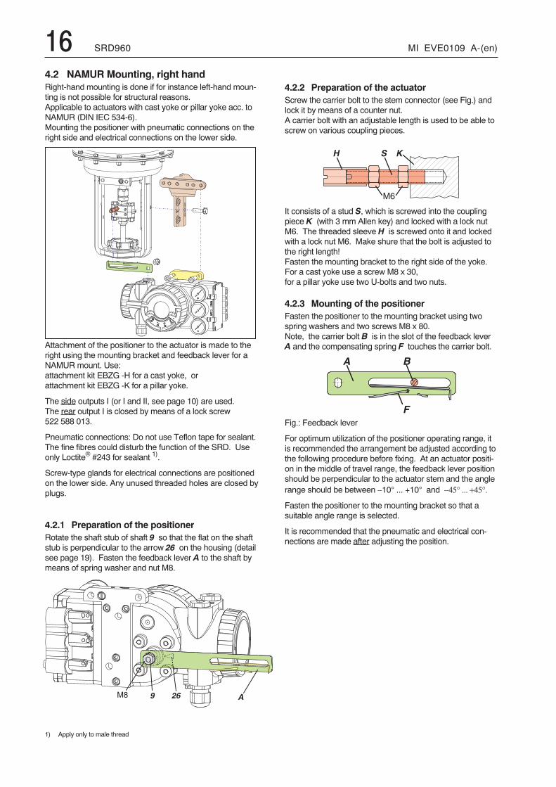
4.2 NAMUR Mounting, right handRight-hand mounting is done if for instance left-hand moun-ting is not possible for structural reasons.Applicable to actuators with cast yoke or pillar yoke acc. toNAMUR (DIN IEC 534-6).Mounting the positioner with pneumatic connections on theright side and electrical connections on the lower side.
Attachment of the positioner to the actuator is made to theright using the mounting bracket and feedback lever for aNAMUR mount. Use:attachment kit EBZG -H for a cast yoke, orattachment kit EBZG -K for a pillar yoke.
The side outputs I (or I and II, see page 10) are used.The rear output I is closed by means of a lock screw522 588 013.
Pneumatic connections: Do not use Teflon tape for sealant.The fine fibres could disturb the function of the SRD. Useonly Loctite® #243 for sealant 1).
Screw-type glands for electrical connections are positionedon the lower side. Any unused threaded holes are closed byplugs.
4.2.1 Preparation of the positionerRotate the shaft stub of shaft 9 so that the flat on the shaftstub is perpendicular to the arrow 26 on the housing (detailsee page 19). Fasten the feedback lever A to the shaft bymeans of spring washer and nut M8.
1) Apply only to male thread
4.2.2 Preparation of the actuatorScrew the carrier bolt to the stem connector (see Fig.) andlock it by means of a counter nut.A carrier bolt with an adjustable length is used to be able toscrew on various coupling pieces.
It consists of a stud S, which is screwed into the couplingpiece K (with 3 mm Allen key) and locked with a lock nutM6. The threaded sleeve H is screwed onto it and lockedwith a lock nut M6. Make shure that the bolt is adjusted tothe right length!Fasten the mounting bracket to the right side of the yoke.For a cast yoke use a screw M8 x 30,for a pillar yoke use two U-bolts and two nuts.
4.2.3 Mounting of the positionerFasten the positioner to the mounting bracket using twospring washers and two screws M8 x 80.Note, the carrier bolt B is in the slot of the feedback leverA and the compensating spring F touches the carrier bolt.
Fig.: Feedback lever
For optimum utilization of the positioner operating range, itis recommended the arrangement be adjusted according tothe following procedure before fixing. At an actuator positi-on in the middle of travel range, the feedback lever positionshould be perpendicular to the actuator stem and the anglerange should be between −10° ... +10° and −45° ... +45°.
Fasten the positioner to the mounting bracket so that asuitable angle range is selected.
It is recommended that the pneumatic and electrical con-nections are made after adjusting the position.
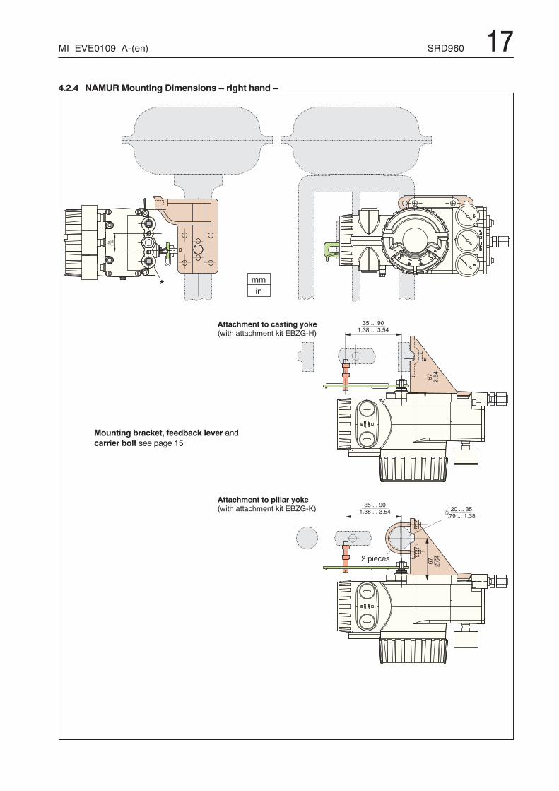
MI EVE0109 A-(en) SRD960 174.2.4 NAMUR Mounting Dimensions – right hand –
� �� �
����
����
> &�
: ( � & & & � � � & : 5 � & & & � : & ( �
: ( � & & & � � � & : 5 � & & & � : & ( �
� & & & � : (& > � � & & & � � & : 5
> &�
C
� � � � $ ( ) � � � � � � � � � � � � � � * � % �) % � � � � � � � � � � � � � � � A � � � / 4 @ < � B ,
� $ � � � � �
� � � � $ ( ) � � � � � � � $ � � � � � � � * � % �) % � � � � � � � � � � � � � � � A � � � / 4 @ < � 6 ,
Mounting bracket, feedback lever andcarrier bolt see page 15
18 SRD960 MI EVE0109 A-(en)
� � 5 � �
�
�
��
M6
B
K S
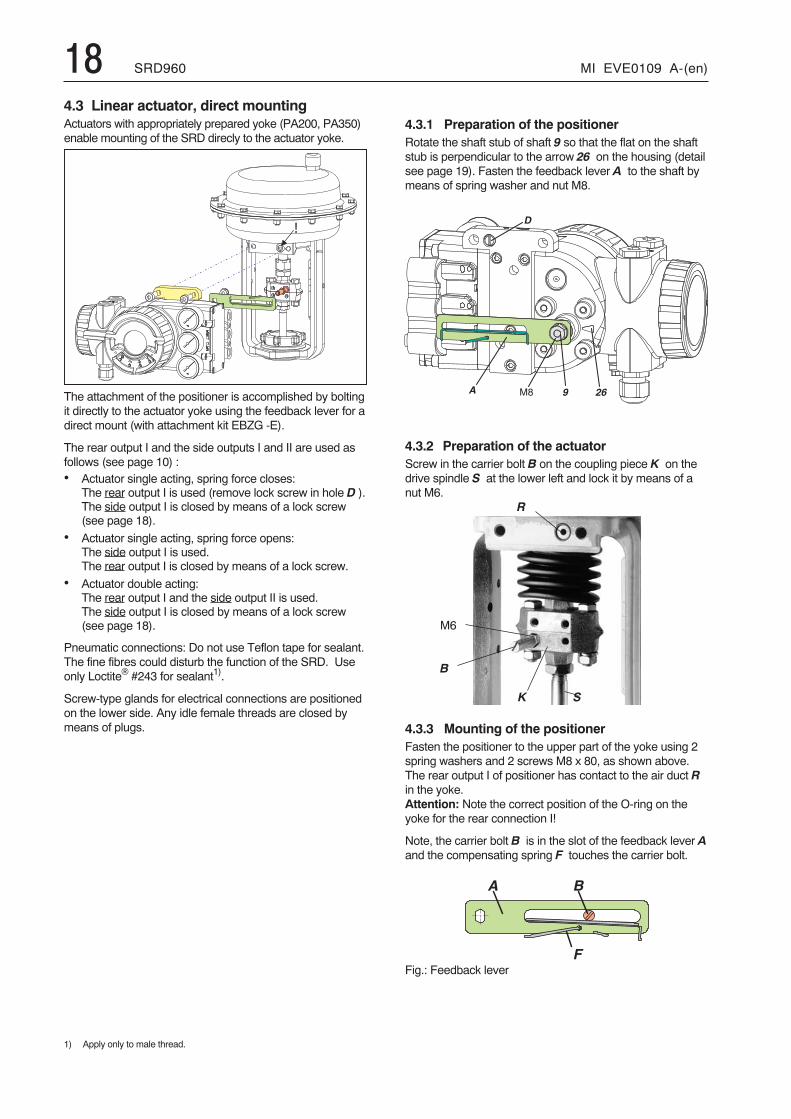
4.3 Linear actuator, direct mountingActuators with appropriately prepared yoke (PA200, PA350)enable mounting of the SRD direcly to the actuator yoke.
The attachment of the positioner is accomplished by boltingit directly to the actuator yoke using the feedback lever for adirect mount (with attachment kit EBZG -E).
The rear output I and the side outputs I and II are used asfollows (see page 10) :• Actuator single acting, spring force closes:
The rear output I is used (remove lock screw in hole D ).The side output I is closed by means of a lock screw(see page 18).
• Actuator single acting, spring force opens:The side output I is used.The rear output I is closed by means of a lock screw.
• Actuator double acting:The rear output I and the side output II is used.The side output I is closed by means of a lock screw(see page 18).
Pneumatic connections: Do not use Teflon tape for sealant.The fine fibres could disturb the function of the SRD. Useonly Loctite® #243 for sealant1).
Screw-type glands for electrical connections are positionedon the lower side. Any idle female threads are closed bymeans of plugs.
1) Apply only to male thread.
4.3.1 Preparation of the positionerRotate the shaft stub of shaft 9 so that the flat on the shaftstub is perpendicular to the arrow 26 on the housing (detailsee page 19). Fasten the feedback lever A to the shaft bymeans of spring washer and nut M8.
4.3.2 Preparation of the actuatorScrew in the carrier bolt B on the coupling piece K on thedrive spindle S at the lower left and lock it by means of anut M6.
R
4.3.3 Mounting of the positionerFasten the positioner to the upper part of the yoke using 2spring washers and 2 screws M8 x 80, as shown above.The rear output I of positioner has contact to the air duct Rin the yoke.Attention: Note the correct position of the O-ring on theyoke for the rear connection I!
Note, the carrier bolt B is in the slot of the feedback lever Aand the compensating spring F touches the carrier bolt.
Fig.: Feedback lever
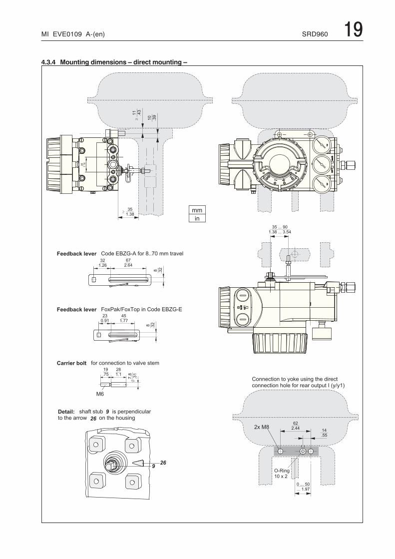
MI EVE0109 A-(en) SRD960 194.3.4 Mounting dimensions – direct mounting –
� � � 2 �
2 3
( )
����
����
� 4��
3 �� 4 3 �
� !� 4 � �
��
4��
��
4�5
� ! � 4 4 4 � 5 �� 4 � � � 4 4 4 � � 4 ! �
� � 4 4 4 � ! �4 4 4 � � 4 5 �
3 �� 4 � �
� �4 ! !
� �� 4 � 3
� 4��
� �� 4 �
�6�
4��
� 54 � !
� �� 4 5 �
� !� 4 � �
�� �
� � � � ! � # � , � D � � � � � / � # � � 1 � 7 � � 8 � " � � � � 4 4 � � � � � � & 9 � %
� � � � ! � # � , � D � � � � � : � � � & ; : � � � � + � ( ) � / � # � � 1 � 7 � � 1
� � � � � � � ! * , $ � � � " � � � ' � ) ) � ' � ( � ) � � � � 9 & % 9 � � � �
� � $ � � , 7 � � � 0 & " � � � $ � � � � � � ( � + � � + � ) # ( ' % & �� � � � 0 � � & � � � � � � � � � � � ) � � 0 � � 0 � ( ) *
/ � ) ) � ' � ( � ) � � � � � � ; � � ( ) * � � 0 � � # ( � � ' � �' � ) ) � ' � ( � ) � 0 � % � � " � � � � � & � � � � + � � < � � � � � �
�
� �
= � � ( ) *� � � � � �
20 SRD960 MI EVE0109 A-(en)
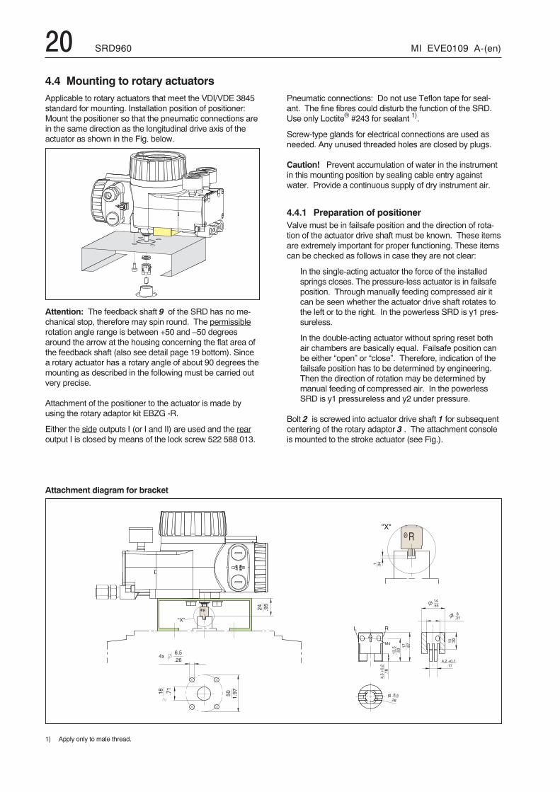
4.4 Mounting to rotary actuatorsApplicable to rotary actuators that meet the VDI/VDE 3845standard for mounting. Installation position of positioner:Mount the positioner so that the pneumatic connections arein the same direction as the longitudinal drive axis of theactuator as shown in the Fig. below.
Attention: The feedback shaft 9 of the SRD has no me-chanical stop, therefore may spin round. The permissiblerotation angle range is between +50 and –50 degreesaround the arrow at the housing concerning the flat area ofthe feedback shaft (also see detail page 19 bottom). Sincea rotary actuator has a rotary angle of about 90 degrees themounting as described in the following must be carried outvery precise.
Attachment of the positioner to the actuator is made byusing the rotary adaptor kit EBZG -R.
Either the side outputs I (or I and II) are used and the rearoutput I is closed by means of the lock screw 522 588 013.
Attachment diagram for bracket
1) Apply only to male thread.
Pneumatic connections: Do not use Teflon tape for seal-ant. The fine fibres could disturb the function of the SRD.Use only Loctite® #243 for sealant 1).
Screw-type glands for electrical connections are used asneeded. Any unused threaded holes are closed by plugs.
Caution! Prevent accumulation of water in the instrumentin this mounting position by sealing cable entry againstwater. Provide a continuous supply of dry instrument air.
4.4.1 Preparation of positionerValve must be in failsafe position and the direction of rota-tion of the actuator drive shaft must be known. These itemsare extremely important for proper functioning. These itemscan be checked as follows in case they are not clear:
In the single-acting actuator the force of the installedsprings closes. The pressure-less actuator is in failsafeposition. Through manually feeding compressed air itcan be seen whether the actuator drive shaft rotates tothe left or to the right. In the powerless SRD is y1 pres-sureless.
In the double-acting actuator without spring reset bothair chambers are basically equal. Failsafe position canbe either “open” or “close”. Therefore, indication of thefailsafe position has to be determined by engineering.Then the direction of rotation may be determined bymanual feeding of compressed air. In the powerlessSRD is y1 pressureless and y2 under pressure.
Bolt 2 is screwed into actuator drive shaft 1 for subsequentcentering of the rotary adaptor 3 . The attachment consoleis mounted to the stroke actuator (see Fig.).
�D ; D
� � &�(
? (
�5 &>�
( �&�>
& � 0
��
��6!
�
&>
&(:
&�5
�?(�E?
� �
4 ! !
�
� ? � E ? �& � >
� &:�
�4 � �
? ( �&
� �
D ; D
���
4��
MI EVE0109 A-(en) SRD960 21
�
�
�
�
�
�
�
�
�
�
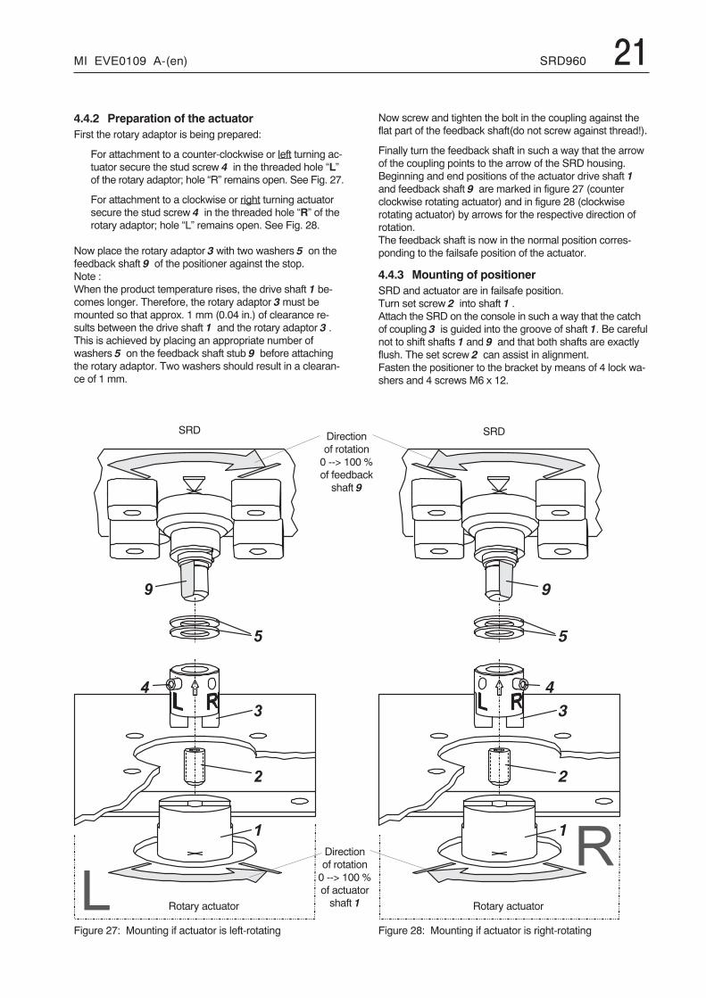
4.4.2 Preparation of the actuatorFirst the rotary adaptor is being prepared:
For attachment to a counter-clockwise or left turning ac-tuator secure the stud screw 4 in the threaded hole “L”of the rotary adaptor; hole “R” remains open. See Fig. 27.
For attachment to a clockwise or right turning actuatorsecure the stud screw 4 in the threaded hole “R” of therotary adaptor; hole “L” remains open. See Fig. 28.
Now place the rotary adaptor 3 with two washers 5 on thefeedback shaft 9 of the positioner against the stop.Note :When the product temperature rises, the drive shaft 1 be-comes longer. Therefore, the rotary adaptor 3must bemounted so that approx. 1 mm (0.04 in.) of clearance re-sults between the drive shaft 1 and the rotary adaptor 3 .This is achieved by placing an appropriate number ofwashers 5 on the feedback shaft stub 9 before attachingthe rotary adaptor. Two washers should result in a clearan-ce of 1 mm.
SRD
Rotary actuator
Figure 27: Mounting if actuator is left-rotating
Now screw and tighten the bolt in the coupling against theflat part of the feedback shaft(do not screw against thread!).
Finally turn the feedback shaft in such a way that the arrowof the coupling points to the arrow of the SRD housing.Beginning and end positions of the actuator drive shaft 1and feedback shaft 9 are marked in figure 27 (counterclockwise rotating actuator) and in figure 28 (clockwiserotating actuator) by arrows for the respective direction ofrotation.The feedback shaft is now in the normal position corres-ponding to the failsafe position of the actuator.
4.4.3 Mounting of positionerSRD and actuator are in failsafe position.Turn set screw 2 into shaft 1 .Attach the SRD on the console in such a way that the catchof coupling 3 is guided into the groove of shaft 1. Be carefulnot to shift shafts 1 and 9 and that both shafts are exactlyflush. The set screw 2 can assist in alignment.Fasten the positioner to the bracket by means of 4 lock wa-shers and 4 screws M6 x 12.
SRD
Rotary actuator
Figure 28: Mounting if actuator is right-rotating
Directionof rotation0 --> 100 %of actuatorshaft 1
Directionof rotation0 --> 100 %of feedbackshaft 9
22 SRD960 MI EVE0109 A-(en)
� � � � � � �
� � � �
� � � �
� ! " � � # � $ � % � # ! � & �' � ! � & � � � � � # ! � & (
� � � �
� � � �
� ! � & � � � � � # ! � &
� � � �� � % � � � � � � # ! � &
� �
�
� �
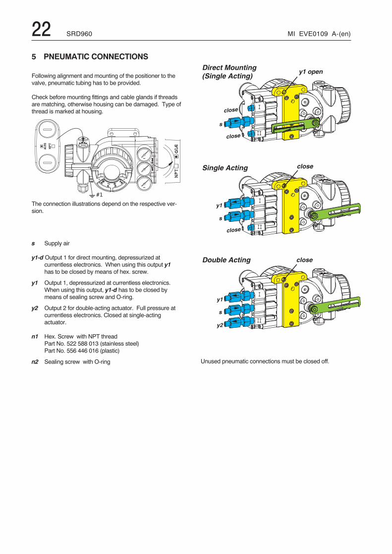
5 PNEUMATIC CONNECTIONS
Following alignment and mounting of the positioner to thevalve, pneumatic tubing has to be provided.
Check before mounting fittings and cable glands if threadsare matching, otherwise housing can be damaged. Type ofthread is marked at housing.
The connection illustrations depend on the respective ver-sion.
s Supply air
y1-d Output 1 for direct mounting, depressurized atcurrentless electronics. When using this output y1has to be closed by means of hex. screw.
y1 Output 1, depressurized at currentless electronics.When using this output, y1-d has to be closed bymeans of sealing screw and O-ring.
y2 Output 2 for double-acting actuator. Full pressure atcurrentless electronics. Closed at single-actingactuator.
n1 Hex. Screw with NPT threadPart No. 522 588 013 (stainless steel)Part No. 556 446 016 (plastic)
n2 Sealing screw with O-ring Unused pneumatic connections must be closed off.
� �
� �� >
� �� ?
� �� ?
! �� >
! �� ?
� �� >
� �� ?
� �� >
� �� ?
� �� >
� �� ?
� !� >
� 3� ?
� �� >
� �� ?
� �� >
� �� ?
� �� >
� � � � � � � � �
� �� ?
� �� >
� ��
� ��
� � � � � � � � �
� �� ?
� �� >
� �
��
� � � � � �� �
� � ! � ! �� �
� ,:
� � � � ! �� �
� ,
� � $ : * � � $
� � � . & ) � 9 � � / � � � � 1 % �� � � . & ) � 9 � � / � � $ � , , � E � � $ � F � * � * 8 8 � 1 %� � � . & ) � 9 � � / � � � , * E 1
< ) + � � � � � � � � � � 8
� * � � � � � . & ) � 9 � � / � * 9 * 8 � � � E � $ � , 1
� + + % � � 9 � % � & * � � 4 4 4 � � / � � � � � � � � 3 � @ � � �
� * � � � � � . & ) � 9 � � / � � � � 5 � � � � � 1 �� � � � � � � . & ) � 9 G � / � � � � � � � � � � � � 0 1
� � ' � ) ) � ' � ( � ) � & ' ' 4 � � � � < 1 / � � � ! � � �� + + % � � 9 � % � & * � � � / � 5 � � � � � � � @ � � �
� � + $ � D � � � � 8 � $ � � F � $ H � / � � � . & ) � 9 9 � � * � � � 9 9 � 1
� � � � $ � * � � , � � � *
� F * � ! � � � � " � * + $ : + $ ; � / � � � . & ) � 9 9 � 1
� ( � ' 0 ( ) * � & + % ( " ( � � A
� F * � ! � � � � " � � � : + $ ; � / � � � . & ) � 9 9 5 1
� � � � � ( � � � � � � 6 � & ' ' 4 � � � � � < � � � 5 � � �� + + % � � 9 � % � & * � B � � / � � � � � � � 3 � @ � � �
� ( ) & � � � ( ) + � � � ( � 0 � ( ) � � � ) & % � + + % � � " � � � ' � ) ) � ' � ( � ) �� " � � ) � � � � � � � ( � ' 0 � �� � ( � ' 0 � , * ; � � � " � � � & � ) � � & % � � + � � & � ( � ) C �
� * ; � $ � * � � C � � � ! � # � 4 � $ * � 3 ) � 8 � � � � � � 0 � � , � � 8 � / � � � . & ) � 9 9 G 1
� ( � ' 0 ( ) * � & + % ( " ( � � � � ( � 0( ) � � ( ) ( ' & % % � � & " �' � ) � � � % � ' ( � ' ( �
8 ) & % � * � � � + � � � � � � � � � � 8� � � � � ( � � � � � � 6 �
+ + % � � 9 � % � & * � � � / � � � � � � � � � @ � � �
� � � � � ( � � � + � � � ( ( � � � � ) � � � & ' ' 4 � � � � � < � � � 5 � � � � � � � � 8 2 D �� + + % � � 9 � % � & * � B � � / � � � @
� * �
, � � � ) � + � � � � ' � ( � ) � ' � � � � " ( � � 6 � � � � � + � ) � � 0 � � ' � 9 � � � & ) # �& ' ' � � � 0 � � � % � ' � � ( ' & % � ' � ) ) � ' � ( � ) � ' � + & � � � ) � 4
� 0 ( � ' � � � � & % � � ) % � ' ; � � 0 � � ' � 9 � � �" � � � � 0 � � � % � ' � � � ) ( ' � ' � + & � � � ) � 4
1 & � � 0 � ' � ) ) � ' � ( � ) � ( ) � � % � ' � � ( ' & % � ' � ) ) � ' � ( � ) � ' � + & � � � ) �
A � � ( � 0 � ( ) � � ( ) ( ' & % % � � & " � � ' � ) � � � % � ' ( � ' ( �
� ( � ' 0 ( ) * � & + % ( " ( � � A
� ( � ' 0 ( ) * � & + % ( " ( � � A � ( � ' 0 ( ) * � & + % ( " ( � � A
� � � � : � � � ( ) � � ( ) ( ' & % % � � & " � � ' ( � ' ( � � + % � & � � � � " � � � � � �� � � � � ' � � � ( " ( ' & � � � � � � # & � & � + % & � � � " � � � & � 4 � � + � � & � ( ) * �� � � � � 9 � % � & * � � � � ' 4
� F * � ! � � � � " � � � � � � � * + $ : + $ ; � / � � � . & ) � 9 9 � 11 & ' 0 � ' 0 & ) ) � % � ' � ) " ( * � & $ % � � & � $ ( ) & � � � ( ) + � � � �$ ( ) & � � � � � + � 6 � � � � $ � � + + % ( � # � � � � � � ) & % % �
< ) + 4 � � = � + 4 � � 1 � & + % � � " � � � ' � ) " ( * � & � ( � ) �
� � H � � � � 8 � $ � � F � $ H � / � � � . & ) � 9 9 � 1
� � � � ( ' � � � � ( � ' 0 � 6 � 8 / � / 6� � � � � ) & % � + + % � � & ) # �� � � � � ) & % � " �
� ( � ' 0 ( ) * � & + % ( " ( � � A
� 0 � � � � � ( � � � + � � � ( ( � � � � ) � � � / � � � . & ) � 9 9 � 1
+ + % �
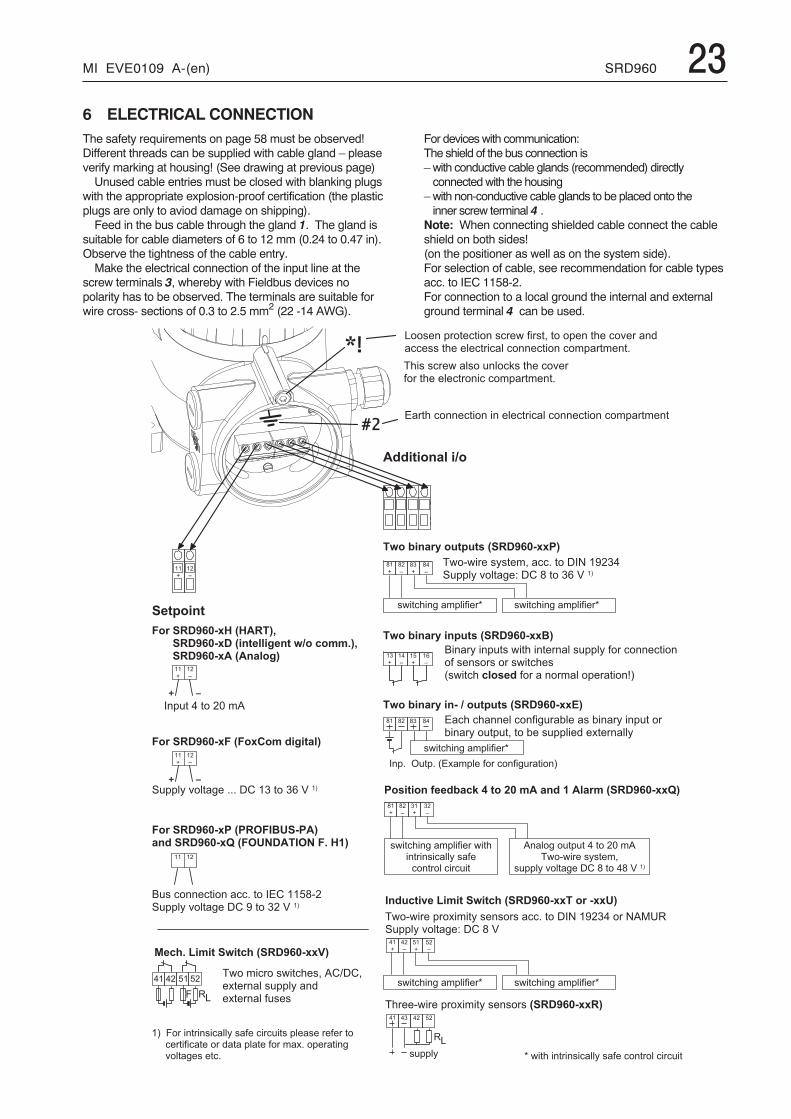
MI EVE0109 A-(en) SRD960 236 ELECTRICAL CONNECTIONThe safety requirements on page 58 must be observed!Different threads can be supplied with cable gland – pleaseverify marking at housing! (See drawing at previous page)Unused cable entries must be closed with blanking plugs
with the appropriate explosion-proof certification (the plasticplugs are only to aviod damage on shipping).Feed in the bus cable through the gland 1. The gland is
suitable for cable diameters of 6 to 12 mm (0.24 to 0.47 in).Observe the tightness of the cable entry.Make the electrical connection of the input line at the
screw terminals 3, whereby with Fieldbus devices nopolarity has to be observed. The terminals are suitable forwire cross- sections of 0.3 to 2.5 mm2 (22 -14 AWG).
For deviceswith communication:The shield of the bus connection is–with conductive cable glands (recommended) directlyconnectedwith the housing
–with non-conductive cable glands to be placed onto theinner screw terminal 4 .
Note: When connecting shielded cable connect the cableshield on both sides!(on the positioner as well as on the system side).For selection of cable, see recommendation for cable typesacc. to IEC 1158-2.For connection to a local ground the internal and externalground terminal 4 can be used.
24 SRD960 MI EVE0109 A-(en)
�
��
�
�
7 OPTIONS
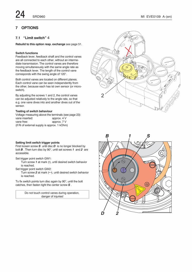
7.1 “Limit switch” 4
Rebuild to this option resp. exchange see page 51.
Switch functionsFeedback lever, feedback shaft and the control vanesare all connected to each other, without an interme-diate transmission. The control vanes are thereforemoving simultaneously with the same angle rate asthe feedback lever. The length of the control vanecorresponds with the swing angle of 120°.
Both control vanes are located on different planes.Each control vane can be seen independently fromthe other, because each has ist own sensor (or micro-switch).
By adjusting the screws 1 and 2, the control vanescan be adjusted relatively to the angle rate, so thate.g. one vane dives into and another dives out of thesensor.
Testing of switch behaviourVoltage measuring above the terminals (see page 23):vane inserted: approx. 4 Vvane free: approx. 7 V(if Ri of external supply is approx. 1 kOhm)
Setting limit switch trigger pointsFirst loosen screw S until disc D is no longer blocked bybolt B . Then turn disc by 90°, until set screws 1 and 2 areaccessible.
Set trigger point switch GW1:Turn screw 1 at mark (•), until desired switch behavioris reached.
Set trigger point switch GW2:Turn screw 2 at mark (• •), until desired switch behavioris reached.
To fix switch points turn disc again by 90°, until the boltcatches, then fasten tight the center screw S .
Do not touch control vanes during operation,danger of injuries!
MI EVE0109 A-(en) SRD960 25
�
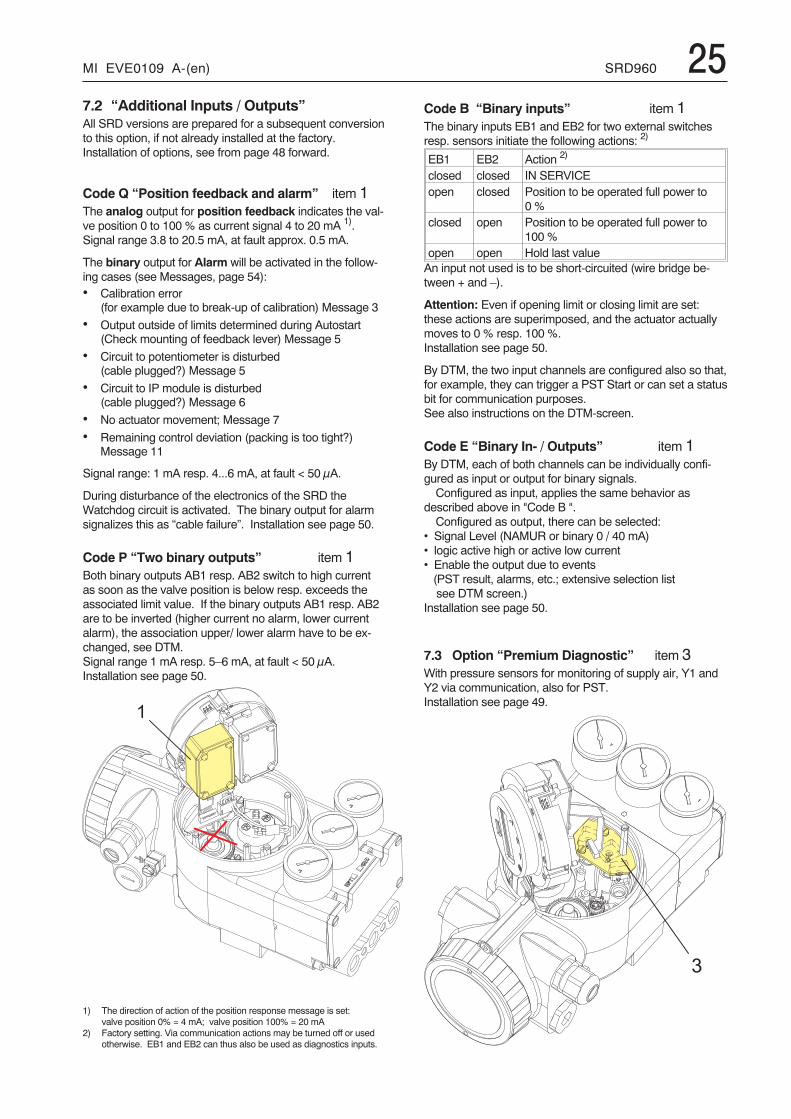
7.2 “Additional Inputs / Outputs”All SRD versions are prepared for a subsequent conversionto this option, if not already installed at the factory.Installation of options, see from page 48 forward.
Code Q “Position feedback and alarm” item 1The analog output for position feedback indicates the val-ve position 0 to 100 % as current signal 4 to 20 mA 1).Signal range 3.8 to 20.5 mA, at fault approx. 0.5 mA.
The binary output for Alarm will be activated in the follow-ing cases (see Messages, page 54):• Calibration error
(for example due to break-up of calibration) Message 3
• Output outside of limits determined during Autostart(Check mounting of feedback lever) Message 5
• Circuit to potentiometer is disturbed(cable plugged?) Message 5
• Circuit to IP module is disturbed(cable plugged?) Message 6
• No actuator movement; Message 7
• Remaining control deviation (packing is too tight?)Message 11
Signal range: 1 mA resp. 4...6 mA, at fault < 50 μA.
During disturbance of the electronics of the SRD theWatchdog circuit is activated. The binary output for alarmsignalizes this as “cable failure”. Installation see page 50.
Code P “Two binary outputs” item 1Both binary outputs AB1 resp. AB2 switch to high currentas soon as the valve position is below resp. exceeds theassociated limit value. If the binary outputs AB1 resp. AB2are to be inverted (higher current no alarm, lower currentalarm), the association upper/ lower alarm have to be ex-changed, see DTM.Signal range 1 mA resp. 5–6 mA, at fault < 50 μA.Installation see page 50.
1) The direction of action of the position response message is set:valve position 0% = 4 mA; valve position 100% = 20 mA
2) Factory setting. Via communication actions may be turned off or usedotherwise. EB1 and EB2 can thus also be used as diagnostics inputs.
Code B “Binary inputs” item 1The binary inputs EB1 and EB2 for two external switchesresp. sensors initiate the following actions: 2)
EB1 EB2 Action 2)
closed closed IN SERVICEopen closed Position to be operated full power to
0 %closed open Position to be operated full power to
100 %open open Hold last valueAn input not used is to be short-circuited (wire bridge be-tween + and –).
Attention: Even if opening limit or closing limit are set:these actions are superimposed, and the actuator actuallymoves to 0 % resp. 100 %.Installation see page 50.
By DTM, the two input channels are configured also so that,for example, they can trigger a PST Start or can set a statusbit for communication purposes.See also instructions on the DTM-screen.
Code E “Binary In- / Outputs” item 1By DTM, each of both channels can be individually confi-gured as input or output for binary signals.Configured as input, applies the same behavior as
described above in "Code B ".Configured as output, there can be selected:
• Signal Level (NAMUR or binary 0 / 40 mA)• logic active high or active low current• Enable the output due to events(PST result, alarms, etc.; extensive selection listsee DTM screen.)
Installation see page 50.
7.3 Option “Premium Diagnostic” item 3With pressure sensors for monitoring of supply air, Y1 andY2 via communication, also for PST.Installation see page 49.
�
26 SRD960 MI EVE0109 A-(en)
��
�
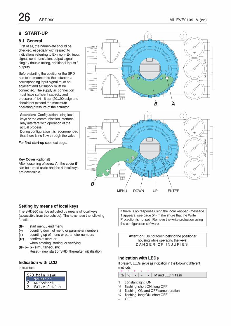
Setting by means of local keysThe SRD960 can be adjusted by means of local keys(accessible from the outside). The keys have the followingfunction:
(�) start menu / end menu(–) counting down of menu or parameter numbers(+) counting up of menu or parameter numbers(�) confirm at start, or
when entering, storing, or verifying(�) (–) (+) simultaneously:
Reset = new start of SRD, thereafter initialization
Indication with LCDIn true text:
��� ���� ��� ������ � ��������� ����� ������
If there is no response using the local key-pad (message1 appears, see page 54) make shure that the WriteProtection is not set ! Remove the write protection usingthe configuration software.
Attention: Do not touch behind the positionerhousing while operating the keys!D A N G E R O F I N J U R I E S !
Indication with LEDsIf present, LEDs serve as indication in the following differentmethods:
M 1 2 3 4
½ ½ - - - M and LED 1 flash
1 constant light, ON¼ flashing: short ON, long OFF½ flashing: ON and OFF same duration¾ flashing: long ON, short OFF– OFF
8 START-UP
8.1 GeneralFirst of all, the nameplate should bechecked, especially with respect toindications referring to Ex / non- Ex, inputsignal, communciation, output signal,single / double acting, additional inputs /outputs.
Before starting the positioner the SRDhas to be mounted to the actuator; acorresponding input signal must beadjacent and air supply must beconnected. The supply air connectionmust have sufficient capacity andpressure of 1.4 - 6 bar (20...90 psig) andshould not exceed the maximumoperating pressure of the actuator.
Attention: Configuration using localkeys or the communication interfacemay interfere with operation of theactual process !During configuration it is recommendedthat there is no flow through the valve.
For first start-up see next page.
Key Cover (optional)After loosening of screw A , the cover Bcan be turned aside and the 4 local keysare accessible.
MENU DOWN UP ENTER
MI EVE0109 A-(en) SRD960 278.2 OPERATION
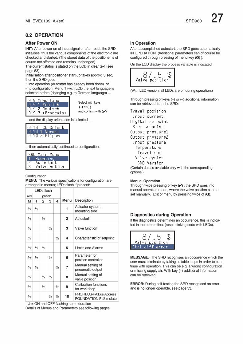
After Power ONINIT: After power on of input signal or after reset, the SRDinitialises, thus the various components of the electronic arechecked and started. (The stored data of the positioner is ofcourse not affected and remains unchanged).The current status is stated on the LCD in clear text (seepage 53).Initialisation after positioner start-up takes approx. 3 sec,then the SRD goes• into operation (Autostart has already been done) or• to configuration, Menu 1 (with LCD the text language isselected before (changing e.g. to German language) ...
��� ��� ��� ���� �� ��������� ����������� ����������
... and the display orientation is selected ...
��� � � !��������� "��#������� ���$$�%
... then automatically continued to configuration:
��� ���� ��� ������ � ��������� ����� ������
ConfigurationMENU: The various specifications for configuration arearranged in menus; LEDs flash if present:
LEDs flash
Menu Descriptionred green
M 1 2 3 4
½ ½ 1 Actuator system,mounting side
½ ½ 2 Autostart
½ ½ 3 Valve function
½ ½ 4 Characteristic of setpoint
½ ½ ½ 5 Limits and Alarms
½ ½ ½ 6 Parameter forposition controller
½ ½ ½ 7 Manual setting ofpneumatic output
½ ½ ½ 8 Manual setting ofvalve position
½ ½ ½ 9 Calibration functionsfor workshop
½ ½ ½ 10 PROFIBUS-PA:BusAddressFOUNDATION F.:Simulate
½ = ON and OFF flashing same durationDetails of Menus and Parameters see following pages.
In OperationAfter accomplished autostart, the SRD goes automaticallyIN OPERATION. (Additional parameters can of course beconfigured through pressing of menu key (�) ).
On the LCD display the process variable is indicated.
87.5 %����� $�������
(With LED version, all LEDs are off during operation.)
Through pressing of keys (+) or (–) additional informationcan be retrieved from the SRD:
&����� $�������
'�$� ������
�� ���� ���$����
���# ���$����
!�$� $������
!�$� $�������
'�$� $������
&�#$������
&����� �#
����� �(����
��� �������(Certain data is available only with the correspondingoptions.)
Manual OperationThrough twice pressing of key (�) , the SRD goes intomanual operation mode, where the valve position can beset manually. Exit of menu by pressing twice of (�).
Diagnostics during OperationIf the diagnostics determines an occurrence, this is indica-ted in the bottom line: (resp. blinking code with LEDs).
87.5 %����� $������� ��� %�)) �����
MESSAGE: The SRD recognises an occurrence which theuser must eliminate by taking suitable steps in order to con-tinue with operation. This can be e.g. a wrong configurationor missing supply air. With key (+) additional informationcan be retrieved.
ERROR: During self-testing the SRD recognised an errorand is no longer operable, see page 53.
Select with keys(+) or (–)and confirm with (�) .
28 SRD960 MI EVE0109 A-(en)
�F
/ � � � � � ' � � � & C
/ � � � � � � � � �
1 � � A
� � 9 �� � � � � � � � �
� � 9 � � � � � � 1 � � A � � � � � � � �$ � � %
� & � � � 9 �
2 � � � � � � � � � � � � � � � � � � 2 � � � � � � � �
- 7 � � / � � - /� & " &
� � � � �% � � � � � �� � 9 �� / � � # 7
� / � � # * *� / � � ! � � � � � � " � � � � # 7 ? � � � � # * *
� � � � � �� G � � � � $ � � � &� � 9 & � G � & $ � � � &� � � � � �
B � 3 � 8 '
B � 3 � � # H 7
) � " � * � # � "� / � � � � � / � � � �
B � 3 � / 7 + / �
B � 3 � � / 7 8
( & �& && &
� :�(>5��
� & �� & � & :� & �
: & �: &
& � & & :
� & �� &
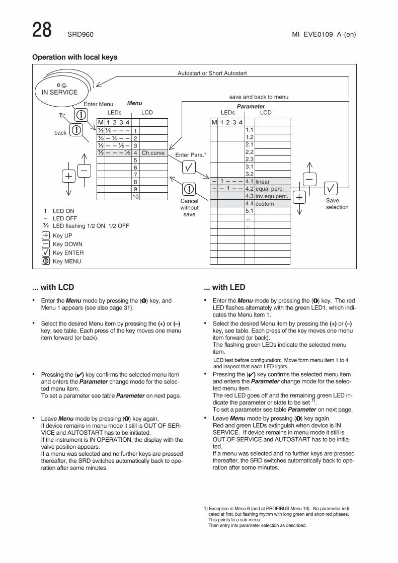
Operation with local keys
... with LCD
• Enter theMenumode by pressing the (�) key, andMenu 1 appears (see also page 31).
• Select the desired Menu item by pressing the (+) or (–)key, see table. Each press of the key moves one menuitem forward (or back).
• Pressing the (�) key confirms the selected menu itemand enters the Parameter change mode for the selec-ted menu item.To set a parameter see table Parameter on next page.
• LeaveMenumode by pressing (�) key again.If device remains in menu mode it still is OUT OF SER-VICE and AUTOSTART has to be initiated.If the instrument is IN OPERATION, the display with thevalve position appears.If a menu was selected and no further keys are pressedthereafter, the SRD switches automatically back to ope-ration after some minutes.
... with LED
• Enter theMenumode by pressing the (�) key. The redLED flashes alternately with the green LED1, which indi-cates the Menu item 1.
• Select the desired Menu item by pressing the (+) or (–)key, see table. Each press of the key moves one menuitem forward (or back).The flashing green LEDs indicate the selected menuitem.LED test before configuration: Move form menu item 1 to 4and inspect that each LED lights.
• Pressing the (�) key confirms the selected menu itemand enters the Parameter change mode for the selec-ted menu item.The red LED goes off and the remaining green LED in-dicate the parameter or state to be set 1).To set a parameter see table Parameter on next page.
• LeaveMenumode by pressing (�) key again.Red and green LEDs extinguish when device is INSERVICE. If device remains in menu mode it still isOUT OF SERVICE and AUTOSTART has to be initia-ted.If a menu was selected and no further keys are pressedthereafter, the SRD switches automatically back to ope-ration after some minutes.
1) Exception in Menu 6 (and at PROFIBUS Menu 10). No parameter indi-cated at first, but flashing rhythm with long green and short red phases.This points to a sub-menu.Then entry into parameter selection as described.
MI EVE0109 A-(en) SRD960 29
� � �� � �
� � � � �� � � � �� � � � � � � � � � � �� � � � �� � � � � � � �
� � � � � � �� �
� �� � � � �� � � �� � � �� � �
� �
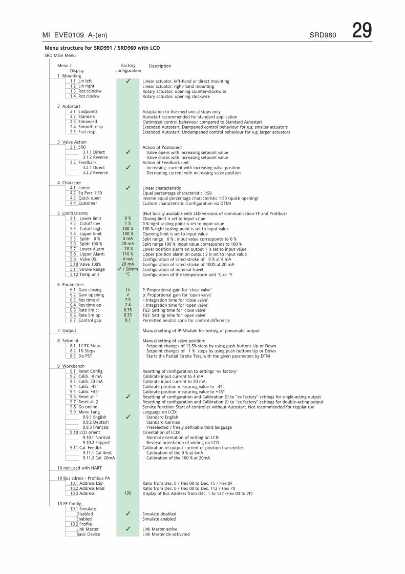
� � � � � � � � � � � � � � � � � � �� � � � � �� � � � � � � � � � �� � � � � � � � � � � �� � � � � � ! � � " � � # � � � �� � � � � � � � � $ � � � � � % " � � � � �� � � � � � � � $ � � � & � # ' " � � �� � � � � � � � � � ! " � ( ( � ! ( ) * � �� � � � � � � � � � ! " � ( � ! ( ) * � � �� � � � � �� � � � � � " ! � " � & " � � � � �� � � � � � � � + � , � ! � � " � � �� � � � � � � � " � � , � & , � �� � � � � � � � + � ' � � ( � , � �� � � � � � � � � � ! ! " ' � & � � � � � �� � � � � � � � - � � " � & � � � � � �� � � � � �� � � � � . � � / � � � ( " � ! � � � � �� � � � � � � � � � � �� � � � � � � � � � � � � � & � ( "� � � � � � � � � � � � � / � & � �� � � � � � � � - � � , 0 � ( )� � � � � � � � � � � � � & � ( "� � � � � � � � � � � � / � & � �� � � � � �� � � � � � ' � & � ( " � & � � � �� � � � � � � � � $ � � � � & � �� � � � � � � � + 1 � 2 � & ( � � 3 � � � �� � � � � � � � � 4 � � ( ) � ! � � � � �� � � � � � � � � � � � " ! � � & � � � � � �� � � � � �� � � � � $ � � � " � � � � & � � � � � �� � � � � � � � � � $ ! * � & � � � � � " � �� � � � � � � � � � � " ! % % � � ! * � �� � � � � � � � � � � � " ! % % � ' � # ' � �� � � � � � � � � � 5 � � � & � � � � � " � �� � � � � � � � � � � � � � " & � � � � � � � �� � � � � � � � � � � � � � " & � � � � � � � �� � � � � � � � � � $ ! * � & � � � � & � � �� � � � � � 6 � � � 5 � � � & � � � � & � � �� � � � � � 7 � � � . � � / � � � � � �� � � � � � � � � . � � / � � � � � � � �� � � � � � � � � � " & ! ) � � � � � # � � �� � � � � � � � 8 � � � � � � � " � �� � � � � �� � � � � 2 � & � � � " � & � � � � �� � � � � � � � � 9 � � � � ( � ! � � � # � �� � � � � � � � 9 � � � � ! � � � � � # � �� � � � � � � � � � � � � " � � � � ( � � �� � � � � � � � � � � � � " � � � � ! � � � �� � � � � � � � � � � " � � � � � � ( � � � �� � � � � � � � � � � " � � � � � � ! � � �� � � � � � � � � � ! � " & ! � � # � � � �� � � � � �� � � � � : � " � � " � � � �� � � � � �� � 6 � � � � " � ! � � " � � � � � � � � �� � � � 6 � � � � � � � � � � " � � � � �� � � � 6 � � � � � � � " � � � � �� � � � 6 � � � � � ! � 2 � 8 � �� � � � � �� � 7 � � ; ! & ) 0 � � ( ' � � � � �� � � � 7 � � � � � � � � " � � ! � % � # � �� � � � 7 � � � � � � � 0 � � � � � � � � �� � � � 7 � � � � � � � � 0 � � � � � � � �� � � � 7 � � � � � � � � 0 � � < � � � � �� � � � 7 � � � � � � � � 0 � � = � � � � �� � � � 7 � � � � � � � � " � � � � � � � �� � � � 7 � � � � � � � � " � � � � � � � � � 7 � 6 � � 9 ! � ! � � � � � � �� � � � 7 � 7 � � � � � � � $ � � # � �� � � � � � 7 � 7 � � � + � # � � � '� � � � � � 7 � 7 � � � � � " � ( '� � � � � � 7 � 7 � � � - & � � > � � �� � � � 7 � � � � $ � � � ! & � � � " � �� � � � � � 7 � � � � � � ? ! & � � �� � � � � � 7 � � � � � - � � � � � ,� � � � 7 � � � � � � � � � - � � , 0 ) � �� � � � � � 7 � � � � � � � � � � � � �� � � � � � 7 � � � � � � � � � � � � �� � � � � �� � � � � � ! " � � � � , � * � " ' � @ � � 8 � � ��� � � � � �� � � � � A � � � � , & � � � � < � 2 & ! % � 0 � � � 2 � ����� � � � � � � � � � , , & � � � � $ � A � �� � � � � � � � � , , & � � � � � � A � �� � � � � � � � � � , , & � � � � �� � � � � �� � � � � - - � � ! � % � # � � � � �� � � � � � � � � � � � � � � " � � �� � � � � � � � � 0 � � , �� � � � � + � � 0 � � , �� � � � � � � � 2 & ! % � � � � �� � � � � $ � � ) � � � � " � & �� � � � � A � � � ( � � � / � ( �
� � � � � � � � � � � � � � � � � � � � � � � � � � � � � � � � � � � � � �
- � ( " ! & ( ! � % � # � & � " � ! �
� � � � � � � � ( & � � " � ! �
$ � � � � & � � ( " � � " ! & B � � � % " < ' � � , � ! & � , � & � ( " � � ! � � " � � #$ � � � � & � � ( " � � " ! & B � & � # ' " < ' � � , � � ! � � " � � #� ! " � & � � ( " � � " ! & B � ! � � � � � # � ( ! � � " � & < ( � ! ( ) * � � �� ! " � & � � ( " � � " ! & B � ! � � � � � # � ( � ! ( ) * � � �
� , � � " � " � ! � � " ! � " ' � � � � ( ' � � � ( � � � � " ! � � � ! � � � � " ! � " � & " � & � ( ! � � � � , � , � % ! & � � " � � , � & , � � � � � � ( � " � ! �: � " � � � C � , � ( ! � " & ! � � 0 � ' � / � ! � & � ( ! � � � & � , � " ! � � " � � , � & , � � � " ! � " � & "+ � " � � , � , � � � " ! � " � & " B � � � � � � � � , � ( ! � " & ! � � 0 � ' � / � ! � & � % ! & � � � # � � � � � � � � & � � ( " � � " ! & �+ � " � � , � , � � � " ! � " � & " B � 5 � , � � � � � � , � ( ! � " & ! � � 0 � ' � / � ! � & � % ! & � � � # � � � � & # � & � � ( " � � " ! & �
� ( " � ! � � ! % � 2 ! � � " � ! � � & 3� � � . � � / � � ! � � � � � * � " ' � � � ( & � � � � � # � � � " � ! � � " � / � � � �� � � . � � / � � ( � ! � � � � * � " ' � � � ( & � � � � � # � � � " � ! � � " � / � � � �� ( " � ! � � ! % � - � � , 0 � ( ) � � � � " 3� � � D � ( & � � � � � # � � ( � & & � � " � * � " ' � � � ( & � � � � � # � / � � / � � � ! � � " � ! �� � � � � ( & � � � � � # � ( � & & � � " � * � " ' � � � ( & � � � � � # � / � � / � � � ! � � " � ! �
$ � � � � & � ( ' � & � ( " � & � � " � ( �+ 1 � � � � � � & ( � � " � # � � ( ' � & � ( " � & � � " � ( � � 3 � �D � / � & � � � � 1 � � � � � � & ( � � " � # � � ( ' � & � ( " � & � � " � ( � � 3 � � � E 1 � � ( ) � ! � � � � � # F� � � " ! � � ( ' � & � ( " � & � � " � ( � E ( ! � % � # � & � " � ! � � / � � � � 8 � F
E ? ! " � � ! ( � � � � � / � � � � 0 � � � * � " ' � $ + � � / � & � � ! � � � ! % � ( ! � � � � � ( � " � ! � � - - � � � , � 2 & ! % � 0 � � F� � ! � � � # � � � � � " � � � � � � " � " ! � � � � � " � / � � � �� � � < " � # ' " � � � � � � � # � � ! � � " � � � � � � " � " ! � � � � � " � / � � � �� � � � � < " � # ' " � � � � � � � # � � ! � � " � � � � � � " � " ! � � � � � " � / � � � �: � � � � � # � � � � � " � � � � � � " � " ! � � � � � " � / � � � �� � � � " � & � � # � � � � � � � � 3 � � � � � " � / � � � � � ( ! & & � � � ! � , � � " ! � � � �� � � � " � & � � # � � � � � � � 3 � � � � � " � / � � � � � ( ! & & � � � ! � , � � " ! � � � � � �$ ! * � & � � ! � � " � ! � � � � � & � � ! � � ! � " � � " � � � � � � � � " � " ! � � � � � " � / � � � �5 � � � & � � ! � � " � ! � � � � � & � � ! � � ! � " � � " � � � � � � � " � " ! � � � � � " � / � � � �� ! � % � # � & � " � ! � � ! % � & � " � , < � " & ! ) � � ! % � � � � � � � � " � � � � �� ! � % � # � & � " � ! � � ! % � & � " � , < � " & ! ) � � ! % � � � � � � � " � � � � �� ! � % � # � & � " � ! � � ! % � � ! � � � � � � " & � / � �� ! � % � # � & � " � ! � � ! % � " ' � � " � � � � & � " � & � � � � � " � � � � ! & � � -
2 3 � 2 & ! � ! & " � ! � � � � # � � � � % ! & � G ( � ! � � � / � � / � H� 3 � 2 & ! � ! & " � ! � � � � # � � � � % ! & � G ! � � � � / � � / � HD 3 � D � " � # & � " � ! � � " � � � � % ! & � G ( � ! � � � / � � / � HD 3 � D � " � # & � " � ! � � " � � � � % ! & � G ! � � � � / � � / � H8 � � 3 � � � " " � � # � " � � � � % ! & � G ( � ! � � � / � � / � H8 � � 3 � � � " " � � # � " � � � � % ! & � G ! � � � � / � � / � H2 � & � � " " � , � � � � " & � � � C ! � � � % ! & � ( ! � " & ! � � , � % % � & � � ( �
� � � � � � � � � " " � � # � ! % � D 2 < � ! , � � � � % ! & � " � � " � � # � ! % � � � � � � � " � ( � ! � " � � "
� � � � � � � � � " " � � # � ! % � / � � / � � � ! � � " � ! � 3� � � � � " � ! � � " � ( ' � � # � � � ! % � � � � � � � " � � � � 0 � � � � � # � � � � ' � 0 � " " ! � � � 5 � � ! & � � ! * �� � � � � " � ! � � " � ( ' � � # � � � ! % � � � � � � � � � " � � � � 0 � � � � � # � � � � ' � 0 � " " ! � � � 5 � � ! & � � ! * �� � � � " � & " � � " ' � � 2 � & " � � � � � " & ! ) � � 8 � � " B � * � " ' � " ' � � # � / � � � � � & � � � " � & � � 0 � � 8 �
� � � � " " � � # � ! % � ( ! � % � # � & � " � ! � � " ! � � � " " � � # � � I � � � % � ( " ! & J� � � � 0 & � " � � � � � � " � ( � & & � � " � " ! � � � � �� � � � 0 & � " � � � � � � " � ( � & & � � " � " ! � � � � �� � � � 0 & � " � � � ! � � " � ! � � � � � � � & � � # � / � � � � � " ! � � � �� � � � 0 & � " � � � ! � � " � ! � � � � � � � & � � # � / � � � � � " ! � = � � �� � � � " " � � # � ! % � ( ! � % � # � & � " � ! � � � � , � � � � � 0 & � " � ! � � E K F � " ! � I � � � % � ( " ! & J � � � " " � � # � � % ! & � � � � # � � < � ( " � � # � ! � " � � "� � � � " " � � # � ! % � ( ! � % � # � & � " � ! � � � � , � � � � � 0 & � " � ! � � E K F � " ! � I � � � % � ( " ! & J � � � " " � � # � � % ! & � , ! � 0 � � < � ( " � � # � ! � " � � "� � & / � ( � � % � � ( " � ! � 3 � � " � & " � ! % � ( ! � " & ! � � � & � * � " ' ! � " � � � " ! � " � & " � � ? ! " � & � ( ! � � � � , � , � % ! & � & � # � � � & � � � �$ � � # � � # � � ! � � $ � � 3� � � � " � � , � & , � + � # � � � '� � � � " � � , � & , � 9 � & � � �� � � 2 & � � � � � ( " � , � � % & � � � � , � % � � � 0 � � � " ' � & , � � � � # � � # �: & � � � " � " � ! � � ! % � $ � � 3� � � ? ! & � � � � ! & � � � " � " � ! � � ! % � * & � " � � # � ! � � $ � �� � � � � / � & � � � ! & � � � " � " � ! � � ! % � * & � " � � # � ! � � $ � �� � � � 0 & � " � ! � � ! % � ! � " � � " � ( � & & � � " � ! % � � ! � � " � ! � � " & � � � � � " " � & 3� � � � � � � 0 & � " � ! � � ! % � " ' � � � � � � � " � � � �� � � � � � � 0 & � " � ! � � ! % � " ' � � � � � � � � � " � � � �
� � " � ! � % & ! � � � � ( � � � � � @ � � � � � � " ! � � � ( � � � � � � @ � � � � -� � " � ! � % & ! � � � � ( � � � � � @ � � � � � � " ! � � � ( � � � � � � @ � � � � �� � � � � � � ! % � A � � � � , , & � � � � % & ! � � � � ( � � � � " ! � � � � E @ � � � � � � " ! � � - F
� � � � � � " � � , � � � 0 � � ,� � � � � � " � � � � � 0 � � ,
$ � � ) � � � � " � & � � ( " � / �$ � � ) � � � � " � & � , � < � ( " � / � " � ,
30 SRD960 MI EVE0109 A-(en)
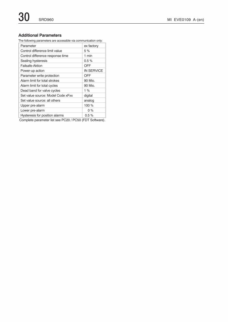
Additional ParametersThe following parameters are accessible via communication only:
Parameter ex factoryControl difference limit value 5 %Control difference response time 1 minSealing hysteresis 0.5 %Failsafe-Aktion OFFPower-up action IN SERVICEParameter write protection OFFAlarm limit for total strokes 90 Mio.Alarm limit for total cycles 90 Mio.Dead band for valve cycles 1 %Set value source: Model Code xFxx digitalSet value source: all others analogUpper pre-alarm 100 %Lower pre-alarm 0 %Hysteresis for position alarms 0.5 %Complete parameter list see PC20 / PC50 (FDT Software).
MI EVE0109 A-(en) SRD960 31
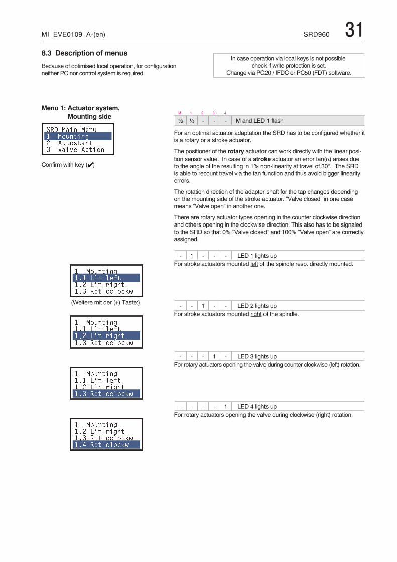
Menu 1: Actuator system,Mounting side
��� ���� ��� ������ � ��������� ����� ������
Confirm with key (�)
������ � ��� ��)��� ��� �� ���� ��� �����*+
(Weitere mit der (+) Taste:)
������ � ��� ��)��� ��� �� ���� ��� �����*+
������ � ��� ��)��� ��� �� ���� ��� �����*+
������ �� ��� �� ���� ��� �����*+�, ��� ����*+
M 1 2 3 4
½ ½ - - - M and LED 1 flash
For an optimal actuator adaptation the SRD has to be configured whether itis a rotary or a stroke actuator.
The positioner of the rotary actuator can work directly with the linear posi-tion sensor value. In case of a stroke actuator an error tan(α) arises dueto the angle of the resulting in 1% non-linearity at travel of 30°. The SRDis able to recount travel via the tan function and thus avoid bigger linearityerrors.
The rotation direction of the adapter shaft for the tap changes dependingon the mounting side of the stroke actuator. “Valve closed” in one casemeans “Valve open” in another one.
There are rotary actuator types opening in the counter clockwise directionand others opening in the clockwise direction. This also has to be signaledto the SRD so that 0% “Valve closed” and 100% “Valve open” are correctlyassigned.
- 1 - - - LED 1 lights upFor stroke actuators mounted left of the spindle resp. directly mounted.
- - 1 - - LED 2 lights upFor stroke actuators mounted right of the spindle.
- - - 1 - LED 3 lights upFor rotary actuators opening the valve during counter clockwise (left) rotation.
- - - - 1 LED 4 lights upFor rotary actuators opening the valve during clockwise (right) rotation.
8.3 Description of menus
Because of optimised local operation, for configurationneither PC nor control system is required.
In case operation via local keys is not possiblecheck if write protection is set.
Change via PC20 / IFDC or PC50 (FDT) software.
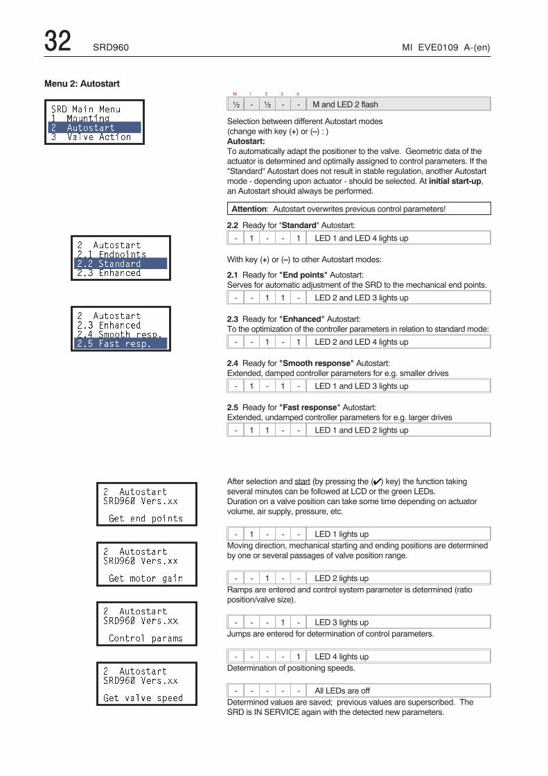
32 SRD960 MI EVE0109 A-(en)
M 1 2 3 4
½ - ½ - - M and LED 2 flash
Selection between different Autostart modes(change with key (+) or (–) : )Autostart:To automatically adapt the positioner to the valve. Geometric data of theactuator is determined and optimally assigned to control parameters. If the"Standard" Autostart does not result in stable regulation, another Autostartmode - depending upon actuator - should be selected. At initial start-up,an Autostart should always be performed.
Attention: Autostart overwrites previous control parameters!
2.2 Ready for "Standard" Autostart:
- 1 - - 1 LED 1 and LED 4 lights up
With key (+) or (–) to other Autostart modes:
2.1 Ready for "End points" Autostart:Serves for automatic adjustment of the SRD to the mechanical end points.
- - 1 1 - LED 2 and LED 3 lights up
2.3 Ready for "Enhanced" Autostart:To the optimization of the controller parameters in relation to standard mode:
- - 1 - 1 LED 2 and LED 4 lights up
2.4 Ready for "Smooth response" Autostart:Extended, damped controller parameters for e.g. smaller drives
- 1 - 1 - LED 1 and LED 3 lights up
2.5 Ready for "Fast response" Autostart:Extended, undamped controller parameters for e.g. larger drives
- 1 1 - - LED 1 and LED 2 lights up
After selection and start (by pressing the (�) key) the function takingseveral minutes can be followed at LCD or the green LEDs.Duration on a valve position can take some time depending on actuatorvolume, air supply, pressure, etc.
- 1 - - - LED 1 lights upMoving direction, mechanical starting and ending positions are determinedby one or several passages of valve position range.
- - 1 - - LED 2 lights upRamps are entered and control system parameter is determined (ratioposition/valve size).
- - - 1 - LED 3 lights upJumps are entered for determination of control parameters.
- - - - 1 LED 4 lights upDetermination of positioning speeds.
- - - - - All LEDs are offDetermined values are saved; previous values are superscribed. TheSRD is IN SERVICE again with the detected new parameters.
Menu 2: Autostart
��� ���� ��� ������ � ��������� ����� ������
� ���������� ��%$�������� ����%��%��� �������%
� ����������� �������%��, �#���� ���$���- ���� ���$�
� ������������.� �����//
0�� ��% $�����
� ������������.� �����//
0�� #���� ���
� ������������.� �����//
������ $���#�
� ������������.� �����//
0�� ����� �$��%
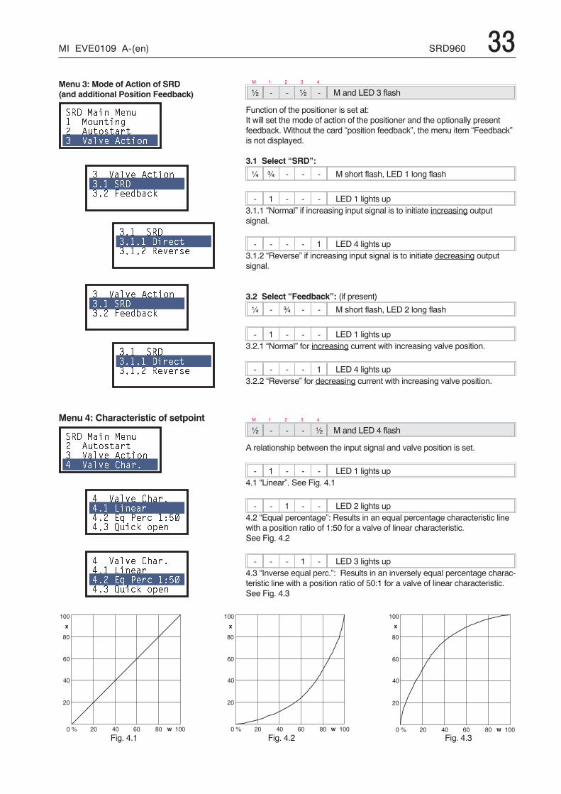
MI EVE0109 A-(en) SRD960 33
� 5 � � I
�
5
�
�
+
� 5 � � I
�
5
�
�
+
� 5 � � I
�
5
�
�
+
Menu 3: Mode of Action of SRD(and additional Position Feedback)
��� ���� ��� ������ � ��������� ����� ������
� ����� �������� ������ ���%1��*
�� ������ ���������� �������
� ����� �������� ������ ���%1��*
�� ������ ���������� �������
Menu 4: Characteristic of setpoint
��� ���� ���� ��������� ����� ������, ����� ����
, ����� ����,� ������,�� �2 3��� 4-�,�� 5��* �$��
, ����� ����,� ������,�� �2 3��� 4-�,�� 5��* �$��
M 1 2 3 4
½ - - ½ - M and LED 3 flash
Function of the positioner is set at:It will set the mode of action of the positioner and the optionally presentfeedback. Without the card “position feedback”, the menu item “Feedback”is not displayed.
3.1 Select “SRD”:
¼ ¾ - - - M short flash, LED 1 long flash
- 1 - - - LED 1 lights up3.1.1 “Normal” if increasing input signal is to initiate increasing outputsignal.
- - - - 1 LED 4 lights up3.1.2 “Reverse” if increasing input signal is to initiate decreasing outputsignal.
3.2 Select “Feedback”: (if present)
¼ - ¾ - - M short flash, LED 2 long flash
- 1 - - - LED 1 lights up3.2.1 “Normal” for increasing current with increasing valve position.
- - - - 1 LED 4 lights up3.2.2 “Reverse” for decreasing current with increasing valve position.
M 1 2 3 4
½ - - - ½ M and LED 4 flash
A relationship between the input signal and valve position is set.
- 1 - - - LED 1 lights up4.1 “Linear”. See Fig. 4.1
- - 1 - - LED 2 lights up4.2 “Equal percentage”: Results in an equal percentage characteristic linewith a position ratio of 1:50 for a valve of linear characteristic.See Fig. 4.2
- - - 1 - LED 3 lights up4.3 “Inverse equal perc.”: Results in an inversely equal percentage charac-teristic line with a position ratio of 50:1 for a valve of linear characteristic.See Fig. 4.3
Fig. 4.1 Fig. 4.2 Fig. 4.3
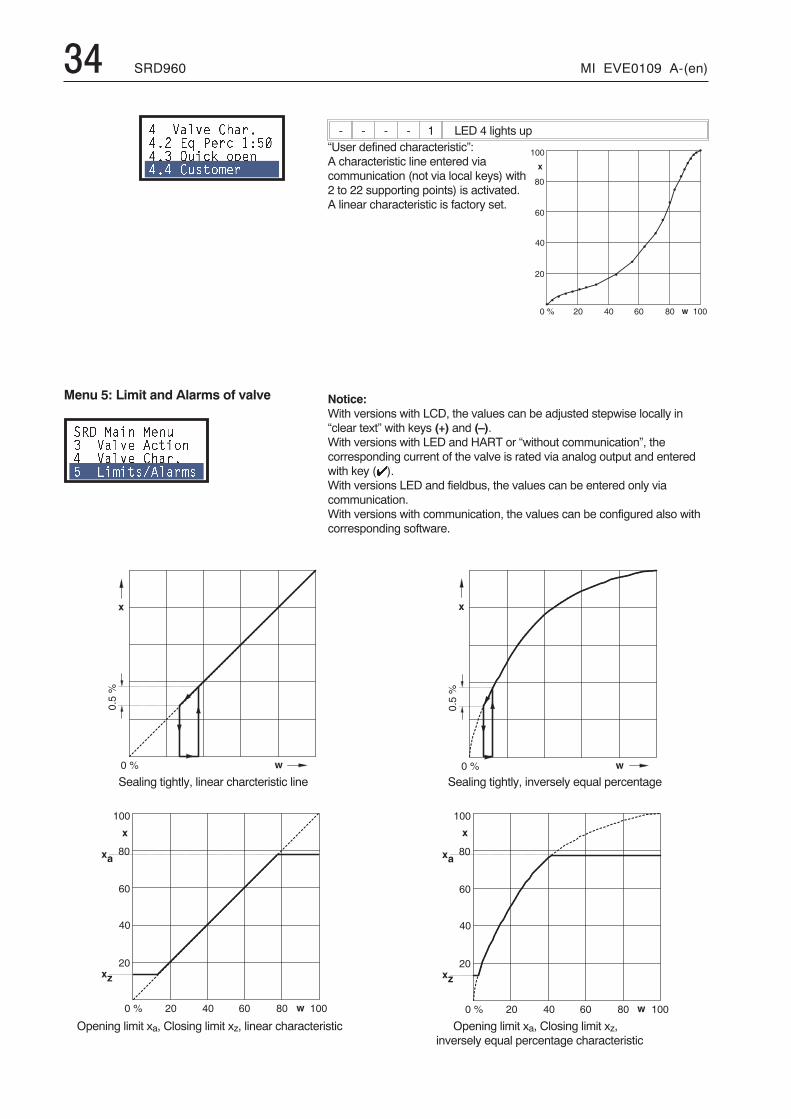
34 SRD960 MI EVE0109 A-(en)
� 5 � � I
�
5
�
�
+
- - - - 1 LED 4 lights up“User defined characteristic”:A characteristic line entered viacommunication (not via local keys) with2 to 22 supporting points) is activated.A linear characteristic is factory set.
Notice:With versions with LCD, the values can be adjusted stepwise locally in“clear text” with keys (+) and (–).With versions with LED and HART or “without communication”, thecorresponding current of the valve is rated via analog output and enteredwith key (�).With versions LED and fieldbus, the values can be entered only viacommunication.With versions with communication, the values can be configured also withcorresponding software.
, ����� ����,�� �2 3��� 4-�,�� 5��* �$��,�, ���#��
Menu 5: Limit and Alarms of valve
��� ���� ���� ����� ������, ����� ����- ��#���6����#�
� I �
+
&(�I
� I �
+
&(�I
� 5 � � I
�
5
�
�
+
+
+
�
,
� 5 � � I
�
5
�
�
+
+
+
�
,
Sealing tightly, linear charcteristic line
Opening limit xa, Closing limit xz, linear characteristic
Sealing tightly, inversely equal percentage
Opening limit xa, Closing limit xz,inversely equal percentage characteristic
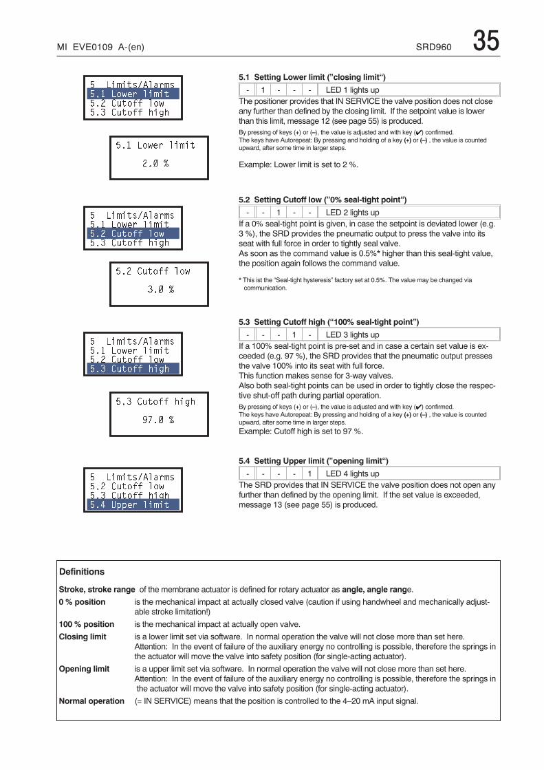
MI EVE0109 A-(en) SRD960 355.1 Setting Lower limit (”closing limit“)
- 1 - - - LED 1 lights upThe positioner provides that IN SERVICE the valve position does not closeany further than defined by the closing limit. If the setpoint value is lowerthan this limit, message 12 (see page 55) is produced.By pressing of keys (+) or (–), the value is adjusted and with key (�) confirmed.The keys have Autorepeat: By pressing and holding of a key (+) or (–) , the value is countedupward, after some time in larger steps.
Example: Lower limit is set to 2 %.
5.2 Setting Cutoff low (”0% seal-tight point“)
- - 1 - - LED 2 lights upIf a 0% seal-tight point is given, in case the setpoint is deviated lower (e.g.3 %), the SRD provides the pneumatic output to press the valve into itsseat with full force in order to tightly seal valve.As soon as the command value is 0.5%* higher than this seal-tight value,the position again follows the command value.
* This ist the “Seal-tight hysteresis” factory set at 0.5%. The value may be changed viacommunication.
5.3 Setting Cutoff high (“100% seal-tight point”)
- - - 1 - LED 3 lights upIf a 100% seal-tight point is pre-set and in case a certain set value is ex-ceeded (e.g. 97 %), the SRD provides that the pneumatic output pressesthe valve 100% into its seat with full force.This function makes sense for 3-way valves.Also both seal-tight points can be used in order to tightly close the respec-tive shut-off path during partial operation.By pressing of keys (+) or (–), the value is adjusted and with key (�) confirmed.The keys have Autorepeat: By pressing and holding of a key (+) or (–) , the value is countedupward, after some time in larger steps.
Example: Cutoff high is set to 97 %.
5.4 Setting Upper limit (”opening limit“)
- - - - 1 LED 4 lights upThe SRD provides that IN SERVICE the valve position does not open anyfurther than defined by the opening limit. If the set value is exceeded,message 13 (see page 55) is produced.
- ��#���6����#�-� ��+�� ��#��-�� ��)) ��+-�� ��)) �� �
-� ��+�� ��#��
��� 7
- ��#���6����#�-� ��+�� ��#��-�� ��)) ��+-�� ��)) �� �
-�� ��)) ��+
��� 7
- ��#���6����#�-� ��+�� ��#��-�� ��)) ��+-�� ��)) �� �
-�� ��)) �� �
�8�� 7
- ��#���6����#�-�� ��)) ��+-�� ��)) �� �-�, 9$$�� ��#��
Definitions
Stroke, stroke range of the membrane actuator is defined for rotary actuator as angle, angle range.
0 % position is the mechanical impact at actually closed valve (caution if using handwheel and mechanically adjust-able stroke limitation!)
100 % position is the mechanical impact at actually open valve.
Closing limit is a lower limit set via software. In normal operation the valve will not close more than set here.Attention: In the event of failure of the auxiliary energy no controlling is possible, therefore the springs inthe actuator will move the valve into safety position (for single-acting actuator).
Opening limit is a upper limit set via software. In normal operation the valve will not close more than set here.Attention: In the event of failure of the auxiliary energy no controlling is possible, therefore the springs inthe actuator will move the valve into safety position (for single-acting actuator).
Normal operation (= IN SERVICE) means that the position is controlled to the 4–20 mA input signal.
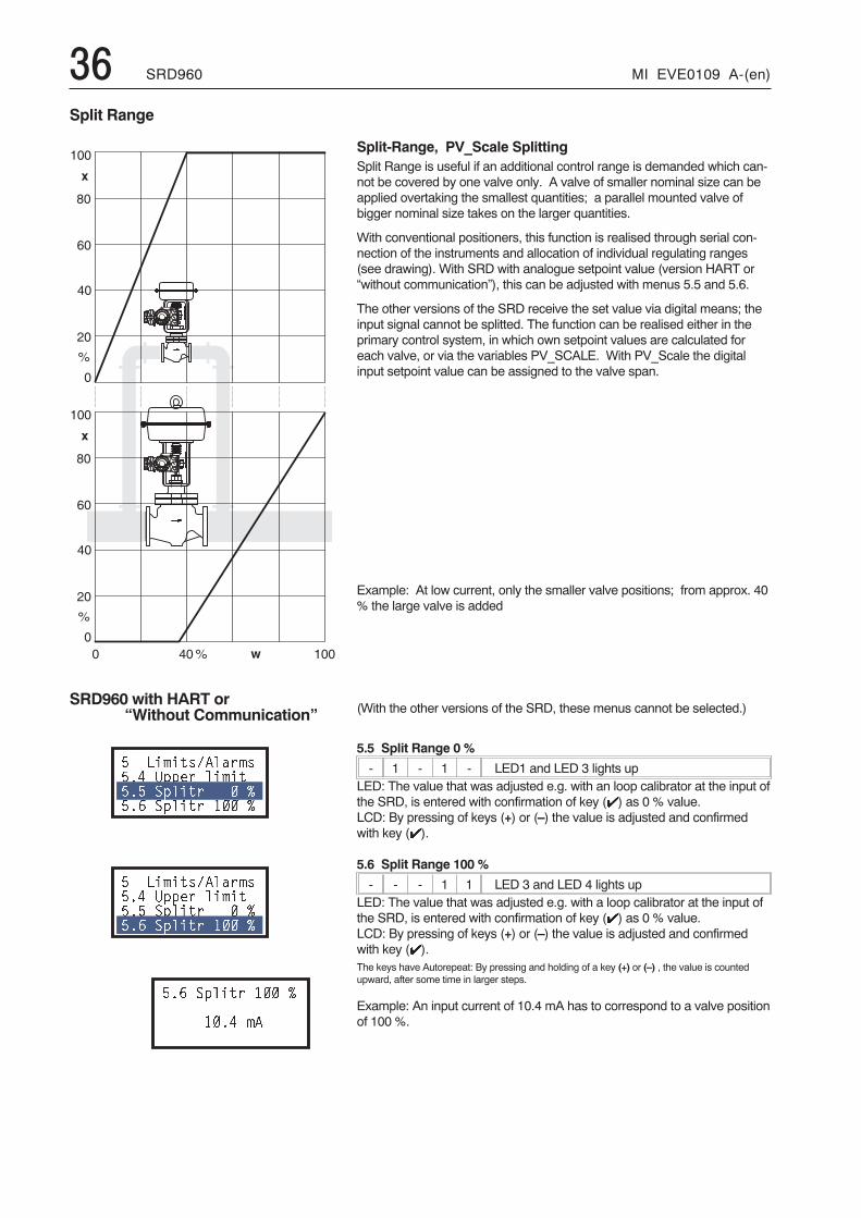
36 SRD960 MI EVE0109 A-(en)
Split-Range, PV_Scale SplittingSplit Range is useful if an additional control range is demanded which can-not be covered by one valve only. A valve of smaller nominal size can beapplied overtaking the smallest quantities; a parallel mounted valve ofbigger nominal size takes on the larger quantities.
With conventional positioners, this function is realised through serial con-nection of the instruments and allocation of individual regulating ranges(see drawing). With SRD with analogue setpoint value (version HART or“without communication”), this can be adjusted with menus 5.5 and 5.6.
The other versions of the SRD receive the set value via digital means; theinput signal cannot be splitted. The function can be realised either in theprimary control system, in which own setpoint values are calculated foreach valve, or via the variables PV_SCALE. With PV_Scale the digitalinput setpoint value can be assigned to the valve span.
Example: At low current, only the smaller valve positions; from approx. 40% the large valve is added
(With the other versions of the SRD, these menus cannot be selected.)
5.5 Split Range 0 %
- 1 - 1 - LED1 and LED 3 lights upLED: The value that was adjusted e.g. with an loop calibrator at the input ofthe SRD, is entered with confirmation of key (�) as 0 % value.LCD: By pressing of keys (+) or (–) the value is adjusted and confirmedwith key (�).
5.6 Split Range 100 %
- - - 1 1 LED 3 and LED 4 lights upLED: The value that was adjusted e.g. with a loop calibrator at the input ofthe SRD, is entered with confirmation of key (�) as 0 % value.LCD: By pressing of keys (+) or (–) the value is adjusted and confirmedwith key (�).The keys have Autorepeat: By pressing and holding of a key (+) or (–) , the value is countedupward, after some time in larger steps.
Example: An input current of 10.4 mA has to correspond to a valve positionof 100 %.
Split Range
SRD960 with HART or“Without Communication”
- ��#���6����#�-�, 9$$�� ��#��-�- �$���� � 7-�. �$���� �� 7
- ��#���6����#�-�, 9$$�� ��#��-�- �$���� � 7-�. �$���� �� 7
-�. �$���� �� 7
��, #�
�
5
�
+
�
5
�
+
I
I
� � I�
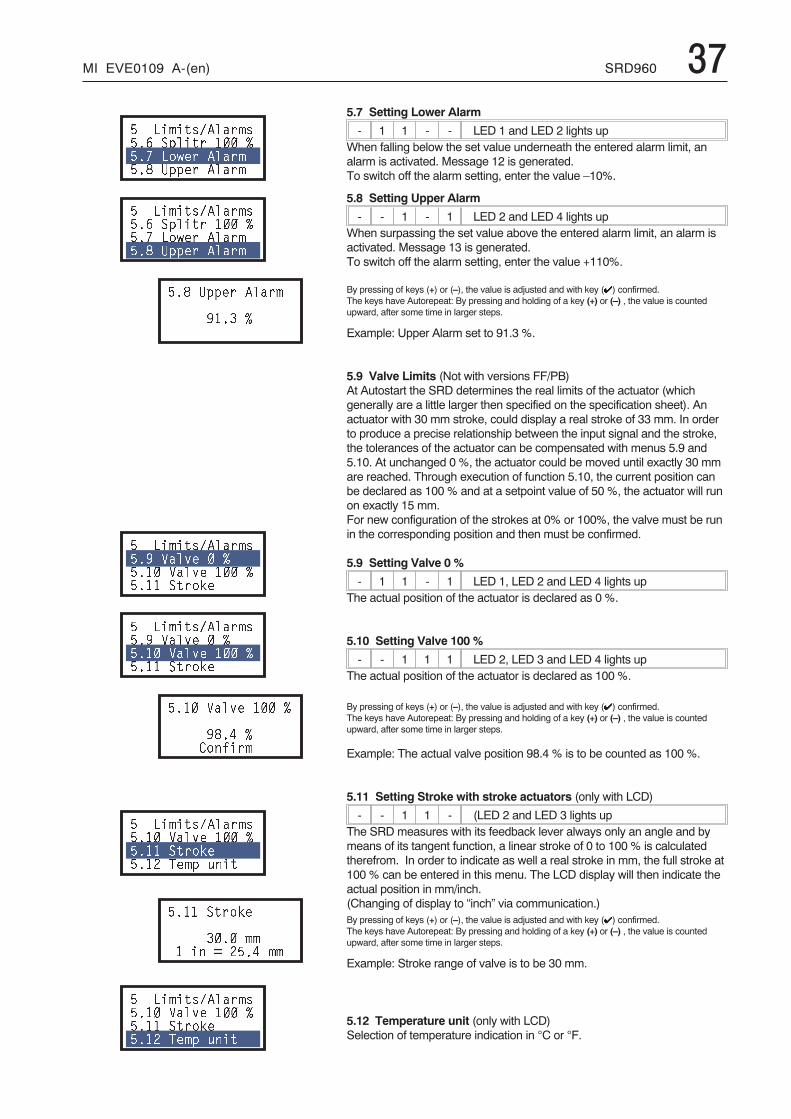
MI EVE0109 A-(en) SRD960 375.7 Setting Lower Alarm
- 1 1 - - LED 1 and LED 2 lights upWhen falling below the set value underneath the entered alarm limit, analarm is activated. Message 12 is generated.To switch off the alarm setting, enter the value –10%.
5.8 Setting Upper Alarm
- - 1 - 1 LED 2 and LED 4 lights upWhen surpassing the set value above the entered alarm limit, an alarm isactivated. Message 13 is generated.To switch off the alarm setting, enter the value +110%.
By pressing of keys (+) or (–), the value is adjusted and with key (�) confirmed.The keys have Autorepeat: By pressing and holding of a key (+) or (–) , the value is countedupward, after some time in larger steps.
Example: Upper Alarm set to 91.3 %.
5.9 Valve Limits (Not with versions FF/PB)At Autostart the SRD determines the real limits of the actuator (whichgenerally are a little larger then specified on the specification sheet). Anactuator with 30 mm stroke, could display a real stroke of 33 mm. In orderto produce a precise relationship between the input signal and the stroke,the tolerances of the actuator can be compensated with menus 5.9 and5.10. At unchanged 0 %, the actuator could be moved until exactly 30 mmare reached. Through execution of function 5.10, the current position canbe declared as 100 % and at a setpoint value of 50 %, the actuator will runon exactly 15 mm.For new configuration of the strokes at 0% or 100%, the valve must be runin the corresponding position and then must be confirmed.
5.9 Setting Valve 0 %
- 1 1 - 1 LED 1, LED 2 and LED 4 lights upThe actual position of the actuator is declared as 0 %.
5.10 Setting Valve 100 %
- - 1 1 1 LED 2, LED 3 and LED 4 lights upThe actual position of the actuator is declared as 100 %.
By pressing of keys (+) or (–), the value is adjusted and with key (�) confirmed.The keys have Autorepeat: By pressing and holding of a key (+) or (–) , the value is countedupward, after some time in larger steps.
Example: The actual valve position 98.4 % is to be counted as 100 %.
5.11 Setting Stroke with stroke actuators (only with LCD)
- - 1 1 - (LED 2 and LED 3 lights upThe SRD measures with its feedback lever always only an angle and bymeans of its tangent function, a linear stroke of 0 to 100 % is calculatedtherefrom. In order to indicate as well a real stroke in mm, the full stroke at100 % can be entered in this menu. The LCD display will then indicate theactual position in mm/inch.(Changing of display to “inch” via communication.)By pressing of keys (+) or (–), the value is adjusted and with key (�) confirmed.The keys have Autorepeat: By pressing and holding of a key (+) or (–) , the value is countedupward, after some time in larger steps.
Example: Stroke range of valve is to be 30 mm.
5.12 Temperature unit (only with LCD)Selection of temperature indication in °C or °F.
- ��#���6����#�-�. �$���� �� 7-�8 ��+�� ����#-�: 9$$�� ����#
- ��#���6����#�-�. �$���� �� 7-�8 ��+�� ����#-�: 9$$�� ����#
-�: 9$$�� ����#
��� 7
- ��#���6����#�-�� ����� � 7-�� ����� �� 7-� ����*�
- ��#���6����#�-�� ����� � 7-�� ����� �� 7-� ����*�
-�� ����� �� 7
�:�, 7 ��)��#
- ��#���6����#�-�� ����� �� 7-� ����*�-�� &�#$ ���
-� ����*�
���� ## �� ; �-�, ##
- ��#���6����#�-�� ����� �� 7-� ����*�-�� &�#$ ���
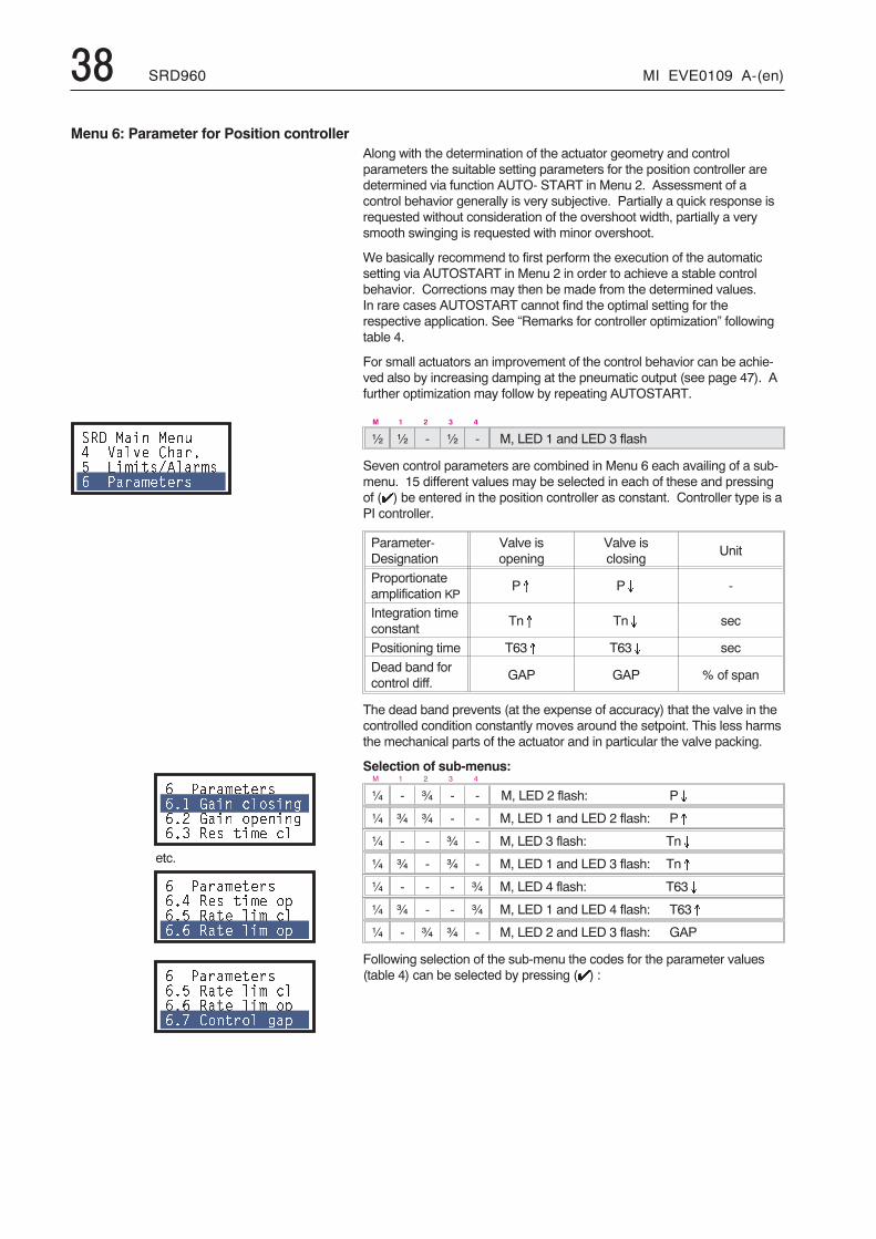
38 SRD960 MI EVE0109 A-(en)
Along with the determination of the actuator geometry and controlparameters the suitable setting parameters for the position controller aredetermined via function AUTO- START in Menu 2. Assessment of acontrol behavior generally is very subjective. Partially a quick response isrequested without consideration of the overshoot width, partially a verysmooth swinging is requested with minor overshoot.
We basically recommend to first perform the execution of the automaticsetting via AUTOSTART in Menu 2 in order to achieve a stable controlbehavior. Corrections may then be made from the determined values.In rare cases AUTOSTART cannot find the optimal setting for therespective application. See “Remarks for controller optimization” followingtable 4.
For small actuators an improvement of the control behavior can be achie-ved also by increasing damping at the pneumatic output (see page 47). Afurther optimization may follow by repeating AUTOSTART.
M 1 2 3 4
½ ½ - ½ - M, LED 1 and LED 3 flash
Seven control parameters are combined in Menu 6 each availing of a sub-menu. 15 different values may be selected in each of these and pressingof (�) be entered in the position controller as constant. Controller type is aPI controller.
Parameter-Designation
Valve isopening
Valve isclosing
Unit
Proportionateamplification KP
P� P� -
Integration timeconstant
Tn� Tn� sec
Positioning time T63� T63� sec
Dead band forcontrol diff.
GAP GAP % of span
The dead band prevents (at the expense of accuracy) that the valve in thecontrolled condition constantly moves around the setpoint. This less harmsthe mechanical parts of the actuator and in particular the valve packing.
Selection of sub-menus:M 1 2 3 4
¼ - ¾ - - M, LED 2 flash: P�
¼ ¾ ¾ - - M, LED 1 and LED 2 flash: P�
¼ - - ¾ - M, LED 3 flash: Tn�
¼ ¾ - ¾ - M, LED 1 and LED 3 flash: Tn�
¼ - - - ¾ M, LED 4 flash: T63�
¼ ¾ - - ¾ M, LED 1 and LED 4 flash: T63�
¼ - ¾ ¾ - M, LED 2 and LED 3 flash: GAP
Following selection of the sub-menu the codes for the parameter values(table 4) can be selected by pressing (�) :
Menu 6: Parameter for Position controller
��� ���� ���, ����� ����- ��#���6����#�. 3���#�����
. 3���#�����
.� 0��� ������
.�� 0��� �$����
.�� ��� ��#� ��
etc.
. 3���#�����
.�, ��� ��#� �$
.�- ���� ��# ��
.�. ���� ��# �$
. 3���#�����
.�- ���� ��# ��
.�. ���� ��# �$
.�8 ������ �$
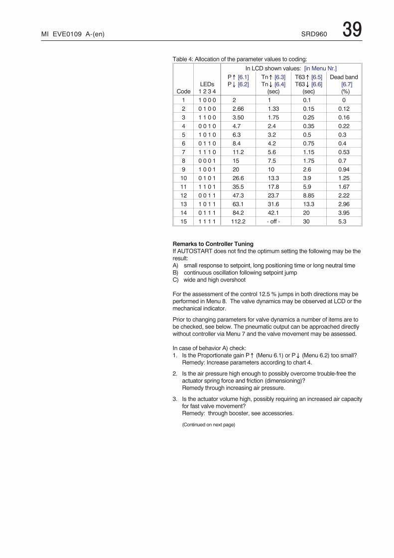
MI EVE0109 A-(en) SRD960 39Table 4: Allocation of the parameter values to coding:
In LCD shown values: [in Menu Nr.]
CodeLEDs1 2 3 4
P� [6.1]P� [6.2]
Tn� [6.3]Tn� [6.4](sec)
T63� [6.5]T63� [6.6]
(sec)
Dead band[6.7](%)
1 1 0 0 0 2 1 0.1 0
2 0 1 0 0 2.66 1.33 0.15 0.12
3 1 1 0 0 3.50 1.75 0.25 0.16
4 0 0 1 0 4.7 2.4 0.35 0.22
5 1 0 1 0 6.3 3.2 0.5 0.3
6 0 1 1 0 8.4 4.2 0.75 0.4
7 1 1 1 0 11.2 5.6 1.15 0.53
8 0 0 0 1 15 7.5 1.75 0.7
9 1 0 0 1 20 10 2.6 0.94
10 0 1 0 1 26.6 13.3 3.9 1.25
11 1 1 0 1 35.5 17.8 5.9 1.67
12 0 0 1 1 47.3 23.7 8.85 2.22
13 1 0 1 1 63.1 31.6 13.3 2.96
14 0 1 1 1 84.2 42.1 20 3.95
15 1 1 1 1 112.2 - off - 30 5.3
Remarks to Controller TuningIf AUTOSTART does not find the optimum setting the following may be theresult:A) small response to setpoint, long positioning time or long neutral timeB) continuous oscillation following setpoint jumpC) wide and high overshoot
For the assessment of the control 12.5 % jumps in both directions may beperformed in Menu 8. The valve dynamics may be observed at LCD or themechanical indicator.
Prior to changing parameters for valve dynamics a number of items are tobe checked, see below. The pneumatic output can be approached directlywithout controller via Menu 7 and the valve movement may be assessed.
In case of behavior A) check:1. Is the Proportionate gain P� (Menu 6.1) or P� (Menu 6.2) too small?
Remedy: Increase parameters according to chart 4.
2. Is the air pressure high enough to possibly overcome trouble-free theactuator spring force and friction (dimensioning)?Remedy through increasing air pressure.
3. Is the actuator volume high, possibly requiring an increased air capacityfor fast valve movement?Remedy: through booster, see accessories.
(Continued on next page)
40 SRD960 MI EVE0109 A-(en)
4. Was AUTOSTART performed in Menu 2 and did mes-sages 8 resp. 9 occur (messages, see table page 41)?Remedy: “AUTOSTART” in Menu 2 resp. observe in-formation in table, page 41.
5. Has the parameter for the positioning time been set at avalue too high?Remedy: decrease both parameters “T63" in Menu 6.5or 6.6 .
6. Is valve packing too tight resulting in a very highfriction?
7. Is the supply air filter blocked?Remedy - see page 47.
8. Has the supply air been contaminated by small oil dropsresp. particles or are pneumatic parts possibly blocked?Remedy: exchange of pneumatic parts; possibly use asuitable air supply station.
Behaviors B) and C) check:1. Has the air supply pressure been set too high?
Remedy: reduce pressure resp. install pressure reducer.2. Is the proportional amplification in Menu 6.1 or 6.2 too
high? The values can possibly be at Code 15.Remedy: In such a case, reduce e.g. to Code 10.
3. Is the air capacity possibly too high, e.g. through spoolvalve or booster?Remedy: Work, if necessary, without booster resp.use version without spool valve.
Changing valve dynamics during behavior A):If valve has a high friction (for example, often the case insmall rotary actuators due to low air supply pressure or dueto a valve seat packing which is too tight) then the valve po-sition gets stuck after a setpoint jump and possibly is recon-trolled via the resetting time Tn, possibly after quite sometime has elapsed.
Basically, the following is possible:a) to accept a remaining deviationb) to accept some response procedures (such as remain-
ing in over-response for a short time, and remainingbelow setpoint and trailing).
When deciding a), “Tn” should become ineffective, tablevalue (15). Compensating “P(kp)” should be increased untilthe setpoint jumps reach the setpoint within a short periodof time and without significant over-response (adapt to bothmovement directions).
When deciding b) start as in a) above. Thereafter “Tn” isreswitched and decreased until the setpoint deviation hasbeen re-controlled within a short period of time and withoutlong after-response (adapt in both movement directions).It is recommended to maintain the Tn’s for both directionsabout the same.If a post oscillation occurs after a setpoint jump, “Tn” is se-lected too small, possibly “P(kp)“ was selected too large.
The positioning time “T63", also called valve damping, doesnot have an effect during AUTOSTART in Menu 2, however,setpoint jumps in Menu 8 reach the position controller in adamped condition which then is not easily stimulated tooscillation. This behavior is also true for the setpoint input.This enables setting the controller to higher “P(kp)“ valueswithout producing oscillations in the process. On one sidethis helps the position control to level disturbances due tofriction, changes in load or air supply pressure changesfaster. On the other hand it helps the superimposed valvecontrol circuit that neutral times in the valve control route dono have such a big effect (stability in valve control circuit).
Changing valve dynamics during behavior B):Increase “Tn” for both movement directions, possibly turn-off and proceed as described in behavior A) alternative b).
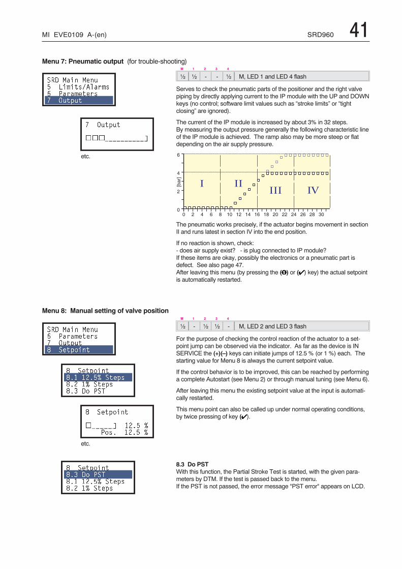
MI EVE0109 A-(en) SRD960 41
M 1 2 3 4
½ ½ - - ½ M, LED 1 and LED 4 flash
Serves to check the pneumatic parts of the positioner and the right valvepiping by directly applying current to the IP module with the UP and DOWNkeys (no control; software limit values such as “stroke limits” or “tightclosing” are ignored).
The current of the IP module is increased by about 3% in 32 steps.By measuring the output pressure generally the following characteristic lineof the IP module is achieved. The ramp also may be more steep or flatdepending on the air supply pressure.
The pneumatic works precisely, if the actuator begins movement in sectionII and runs latest in section IV into the end position.
If no reaction is shown, check:- does air supply exist? - is plug connected to IP module?If these items are okay, possibly the electronics or a pneumatic part isdefect. See also page 47.After leaving this menu (by pressing the (�) or (�) key) the actual setpointis automatically restarted.
M 1 2 3 4
½ - ½ ½ - M, LED 2 and LED 3 flash
For the purpose of checking the control reaction of the actuator to a set-point jump can be observed via the indicator. As far as the device is INSERVICE the (+)(–) keys can initiate jumps of 12.5 % (or 1 %) each. Thestarting value for Menu 8 is always the current setpoint value.
If the control behavior is to be improved, this can be reached by performinga complete Autostart (see Menu 2) or through manual tuning (see Menu 6).
After leaving this menu the existing setpoint value at the input is automati-cally restarted.
This menu point can also be called up under normal operating conditions,by twice pressing of key (�).
8.3 Do PSTWith this function, the Partial Stroke Test is started, with the given para-meters by DTM. If the test is passed back to the menu.If the PST is not passed, the error message "PST error" appears on LCD.
Menu 7: Pneumatic output (for trouble-shooting)
��� ���� ���- ��#���6����#�. 3���#�����8 !�$�
8 !�$�
<<<==========>
etc.
Menu 8: Manual setting of valve position
��� ���� ���. 3���#�����8 !�$�: ���$����
: ���$����:� ��-7 ���$�:�� 7 ���$�:�� �� 3�&
: ���$����
<=====> ��- 73��� ��- 7
etc.
: ���$����:�� �� 3�&:� ��-7 ���$�:�� 7 ���$�
� 5 � � � � � � 5 � 5 :
�
J1��K
� � �� � � � �
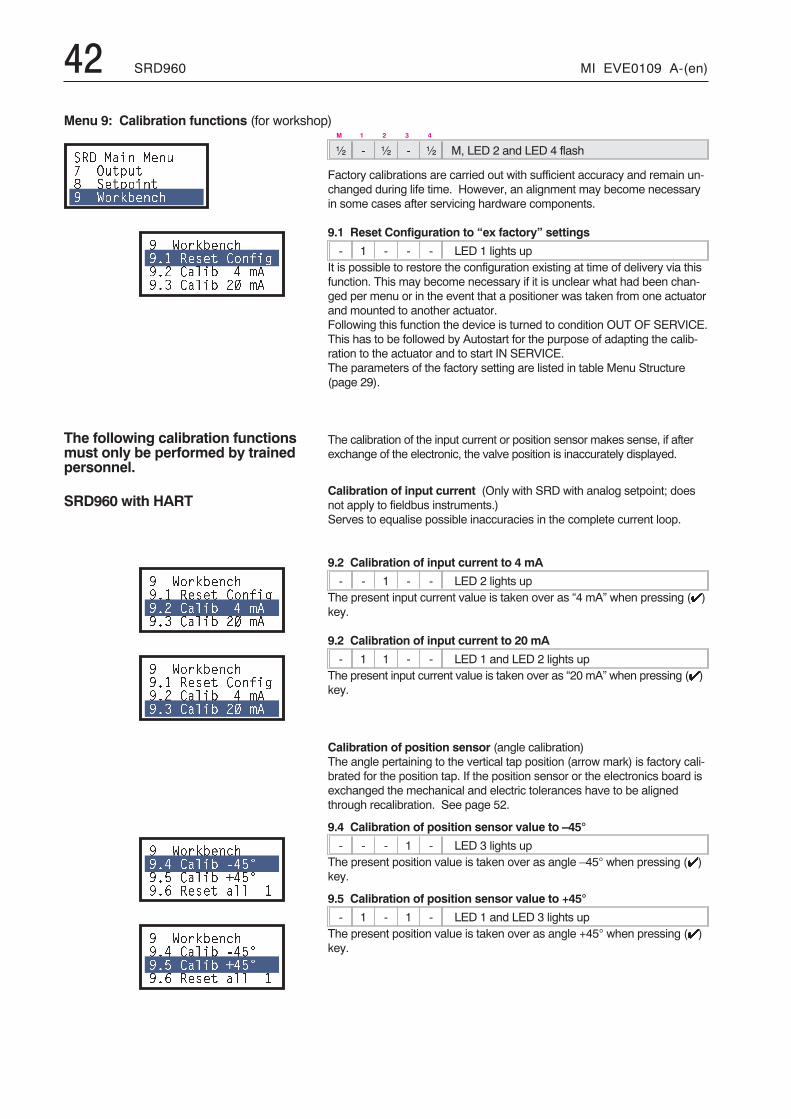
42 SRD960 MI EVE0109 A-(en)
M 1 2 3 4
½ - ½ - ½ M, LED 2 and LED 4 flash
Factory calibrations are carried out with sufficient accuracy and remain un-changed during life time. However, an alignment may become necessaryin some cases after servicing hardware components.
9.1 Reset Configuration to “ex factory” settings
- 1 - - - LED 1 lights upIt is possible to restore the configuration existing at time of delivery via thisfunction. This may become necessary if it is unclear what had been chan-ged per menu or in the event that a positioner was taken from one actuatorand mounted to another actuator.Following this function the device is turned to condition OUT OF SERVICE.This has to be followed by Autostart for the purpose of adapting the calib-ration to the actuator and to start IN SERVICE.The parameters of the factory setting are listed in table Menu Structure(page 29).
The calibration of the input current or position sensor makes sense, if afterexchange of the electronic, the valve position is inaccurately displayed.
Calibration of input current (Only with SRD with analog setpoint; doesnot apply to fieldbus instruments.)Serves to equalise possible inaccuracies in the complete current loop.
9.2 Calibration of input current to 4 mA
- - 1 - - LED 2 lights upThe present input current value is taken over as “4 mA” when pressing (�)key.
9.2 Calibration of input current to 20 mA
- 1 1 - - LED 1 and LED 2 lights upThe present input current value is taken over as “20 mA” when pressing (�)key.
Calibration of position sensor (angle calibration)The angle pertaining to the vertical tap position (arrow mark) is factory cali-brated for the position tap. If the position sensor or the electronics board isexchanged the mechanical and electric tolerances have to be alignedthrough recalibration. See page 52.
9.4 Calibration of position sensor value to –45°
- - - 1 - LED 3 lights upThe present position value is taken over as angle –45° when pressing (�)key.
9.5 Calibration of position sensor value to +45°
- 1 - 1 - LED 1 and LED 3 lights upThe present position value is taken over as angle +45° when pressing (�)key.
Menu 9: Calibration functions (for workshop)
��� ���� ���8 !�$�: ���$����� ?��*1����
� ?��*1������ ����� ��)� ��� ���1 , #���� ���1 �� #�
The following calibration functionsmust only be performed by trainedpersonnel.
SRD960 with HART
� ?��*1������ ����� ��)� ��� ���1 , #���� ���1 �� #�
� ?��*1������ ����� ��)� ��� ���1 , #���� ���1 �� #�
� ?��*1������, ���1 @,-A��- ���1 B,-A��. ����� ���
� ?��*1������, ���1 @,-A��- ���1 B,-A��. ����� ���
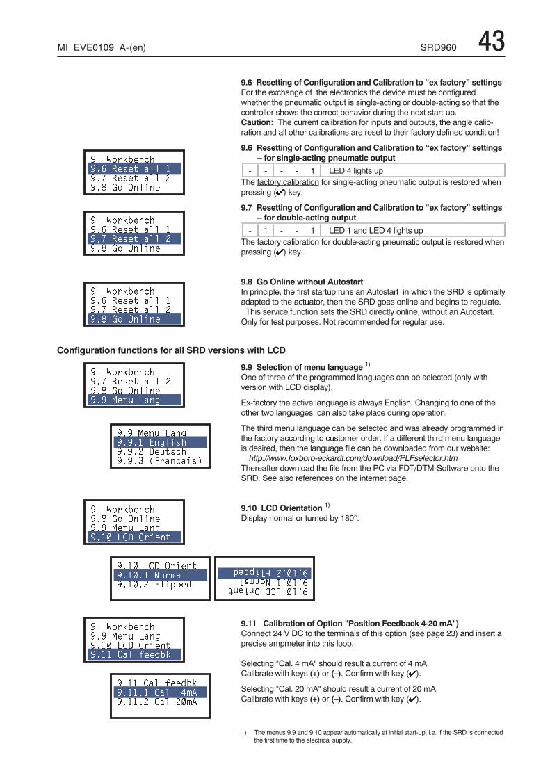
MI EVE0109 A-(en) SRD960 439.6 Resetting of Configuration and Calibration to “ex factory” settingsFor the exchange of the electronics the device must be configuredwhether the pneumatic output is single-acting or double-acting so that thecontroller shows the correct behavior during the next start-up.Caution: The current calibration for inputs and outputs, the angle calib-ration and all other calibrations are reset to their factory defined condition!
9.6 Resetting of Configuration and Calibration to “ex factory” settings– for single-acting pneumatic output
- - - - 1 LED 4 lights upThe factory calibration for single-acting pneumatic output is restored whenpressing (�) key.
9.7 Resetting of Configuration and Calibration to “ex factory” settings– for double-acting output
- 1 - - 1 LED 1 and LED 4 lights upThe factory calibration for double-acting pneumatic output is restored whenpressing (�) key.
9.8 Go Online without AutostartIn principle, the first startup runs an Autostart in which the SRD is optimallyadapted to the actuator, then the SRD goes online and begins to regulate.This service function sets the SRD directly online, without an Autostart.Only for test purposes. Not recommended for regular use.
9.9 Selection of menu language 1)
One of three of the programmed languages can be selected (only withversion with LCD display).
Ex-factory the active language is always English. Changing to one of theother two languages, can also take place during operation.
The third menu language can be selected and was already programmed inthe factory according to customer order. If a different third menu languageis desired, then the language file can be downloaded from our website:http://www.foxboro-eckardt.com/download/PLFselector.htm
Thereafter download the file from the PC via FDT/DTM-Software onto theSRD. See also references on the internet page.
9.10 LCD Orientation 1)
Display normal or turned by 180°.
9.11 Calibration of Option "Position Feedback 4-20 mA")Connect 24 V DC to the terminals of this option (see page 23) and insert aprecise ampmeter into this loop.
Selecting "Cal. 4 mA" should result a current of 4 mA.Calibrate with keys (+) or (–). Confirm with key (�).
Selecting "Cal. 20 mA" should result a current of 20 mA.Calibrate with keys (+) or (–). Confirm with key (�).
1) The menus 9.9 and 9.10 appear automatically at initial start-up, i.e. if the SRD is connectedthe first time to the electrical supply.
� ?��*1������. ����� ��� ��8 ����� ��� ���: 0� !�����
� ?��*1������. ����� ��� ��8 ����� ��� ���: 0� !�����
� ?��*1������. ����� ��� ��8 ����� ��� ���: 0� !�����
� ?��*1������8 ����� ��� ���: 0� !�������� ��� ���
��� ��� ��� ���� �� ��������� ����������� ����������
� ?��*1������: 0� !�������� ��� ��� ��� � � !�����
��� � � !��������� "��#������� ���$$�%
� ?��*1������� ��� ��� ��� � � !������� �� )��%1*
�� �� )��%1*��� �� ,#����� �� ��#�
���� �!���������"��#����������$$�%
Configuration functions for all SRD versions with LCD
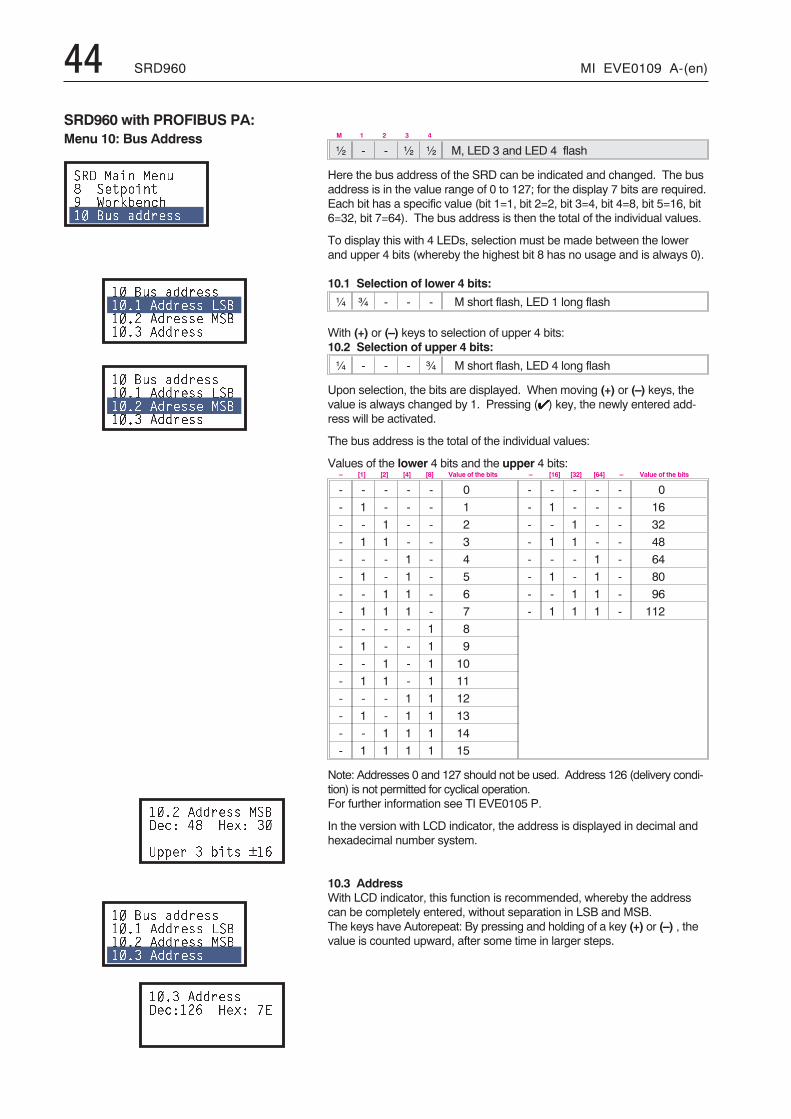
44 SRD960 MI EVE0109 A-(en)
M 1 2 3 4
½ - - ½ ½ M, LED 3 and LED 4 flash
Here the bus address of the SRD can be indicated and changed. The busaddress is in the value range of 0 to 127; for the display 7 bits are required.Each bit has a specific value (bit 1=1, bit 2=2, bit 3=4, bit 4=8, bit 5=16, bit6=32, bit 7=64). The bus address is then the total of the individual values.
To display this with 4 LEDs, selection must be made between the lowerand upper 4 bits (whereby the highest bit 8 has no usage and is always 0).
10.1 Selection of lower 4 bits:
¼ ¾ - - - M short flash, LED 1 long flash
With (+) or (–) keys to selection of upper 4 bits:10.2 Selection of upper 4 bits:
¼ - - - ¾ M short flash, LED 4 long flash
Upon selection, the bits are displayed. When moving (+) or (–) keys, thevalue is always changed by 1. Pressing (�) key, the newly entered add-ress will be activated.
The bus address is the total of the individual values:
Values of the lower 4 bits and the upper 4 bits:– [1] [2] [4] [8] Value of the bits – [16] [32] [64] – Value of the bits
- - - - - 0 - - - - - 0
- 1 - - - 1 - 1 - - - 16
- - 1 - - 2 - - 1 - - 32
- 1 1 - - 3 - 1 1 - - 48
- - - 1 - 4 - - - 1 - 64
- 1 - 1 - 5 - 1 - 1 - 80
- - 1 1 - 6 - - 1 1 - 96
- 1 1 1 - 7 - 1 1 1 - 112
- - - - 1 8
- 1 - - 1 9
- - 1 - 1 10
- 1 1 - 1 11
- - - 1 1 12
- 1 - 1 1 13
- - 1 1 1 14
- 1 1 1 1 15
Note: Addresses 0 and 127 should not be used. Address 126 (delivery condi-tion) is not permitted for cyclical operation.For further information see TI EVE0105 P.
In the version with LCD indicator, the address is displayed in decimal andhexadecimal number system.
10.3 AddressWith LCD indicator, this function is recommended, whereby the addresscan be completely entered, without separation in LSB and MSB.The keys have Autorepeat: By pressing and holding of a key (+) or (–) , thevalue is counted upward, after some time in larger steps.
SRD960 with PROFIBUS PA:Menu 10: Bus Address
��� ���� ���: ���$����� ?��*1����� C� �%%����
� C� �%%������ �%%���� ��C��� �%����� ��C��� �%%����
� C� �%%������ �%%���� ��C��� �%����� ��C��� �%%����
��� �%%���� ��C���4 ,: D�/4 ��
9$$�� � 1��� E.
� C� �%%������ �%%���� ��C��� �%%���� ��C��� �%%����
��� �%%�������4�. D�/4 8�
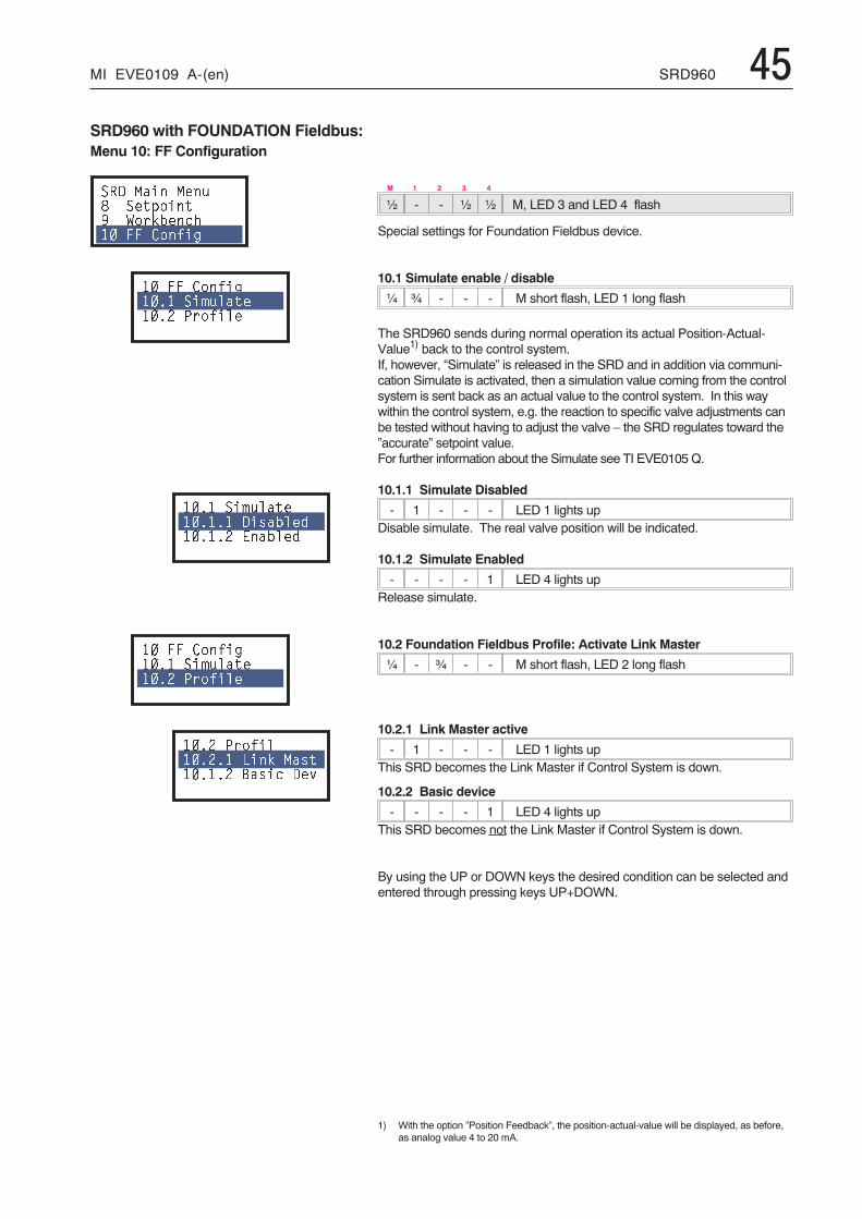
MI EVE0109 A-(en) SRD960 45
M 1 2 3 4
½ - - ½ ½ M, LED 3 and LED 4 flash
Special settings for Foundation Fieldbus device.
10.1 Simulate enable / disable
¼ ¾ - - - M short flash, LED 1 long flash
The SRD960 sends during normal operation its actual Position-Actual-Value1) back to the control system.If, however, “Simulate” is released in the SRD and in addition via communi-cation Simulate is activated, then a simulation value coming from the controlsystem is sent back as an actual value to the control system. In this waywithin the control system, e.g. the reaction to specific valve adjustments canbe tested without having to adjust the valve – the SRD regulates toward the”accurate” setpoint value.For further information about the Simulate see TI EVE0105Q.
10.1.1 Simulate Disabled
- 1 - - - LED 1 lights upDisable simulate. The real valve position will be indicated.
10.1.2 Simulate Enabled
- - - - 1 LED 4 lights upRelease simulate.
10.2 Foundation Fieldbus Profile: Activate Link Master
¼ - ¾ - - M short flash, LED 2 long flash
10.2.1 Link Master active
- 1 - - - LED 1 lights upThis SRD becomes the Link Master if Control System is down.
10.2.2 Basic device
- - - - 1 LED 4 lights upThis SRD becomes not the Link Master if Control System is down.
By using the UP or DOWN keys the desired condition can be selected andentered through pressing keys UP+DOWN.
1) With the option ”Position Feedback”, the position-actual-value will be displayed, as before,as analog value 4 to 20 mA.
SRD960 with FOUNDATION Fieldbus:Menu 10: FF Configuration
��� ���� ���: ���$����� ?��*1����� �� ��)�
� �� ��)� �� ��#������� 3��)���
�� ��#������� ����1��%���� ���1��%
� �� ��)� �� ��#������� 3��)���
��� 3��)������ ���* �������� C���� ���

46 SRD960 MI EVE0109 A-(en)
9 DECOMMISSIONINGBefore decommissioning the unit, disconnect the supply airand the electrical input signal.
After disconnecting the electrical input signal the last con-firmed configuration of the positioner is preserved in thememory.
Exchange of deviceIf a temporary decommissioning of the SRD and a latermounting to another actuator has to be carried out, beforedisconnecting, we recommend to Reset Configuration inMenu 9.1. So the default settings ”Ex-Factory” are re-activated. This facilitates a later recommissioning.
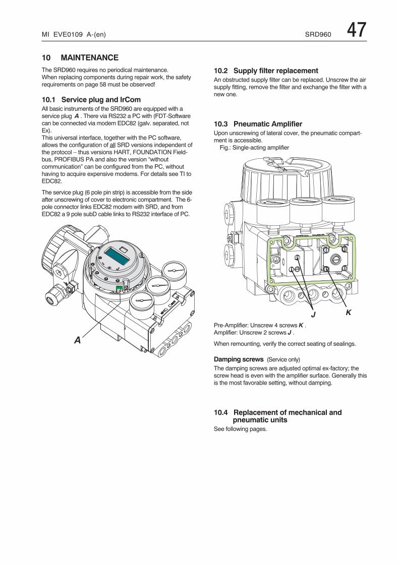
MI EVE0109 A-(en) SRD960 47
+ �
�
10 MAINTENANCEThe SRD960 requires no periodical maintenance.When replacing components during repair work, the safetyrequirements on page 58 must be observed!
10.1 Service plug and IrComAll basic instruments of the SRD960 are equipped with aservice plug A . There via RS232 a PC with (FDT-Softwarecan be connected via modem EDC82 (galv. separated, notEx).This universal interface, together with the PC software,allows the configuration of all SRD versions independent ofthe protocol – thus versions HART, FOUNDATION Field-bus, PROFIBUS PA and also the version “withoutcommunication” can be configured from the PC, withouthaving to acquire expensive modems. For details see TI toEDC82.
The service plug (6 pole pin strip) is accessible from the sideafter unscrewing of cover to electronic compartment. The 6-pole connector links EDC82 modem with SRD, and fromEDC82 a 9 pole subD cable links to RS232 interface of PC.
10.2 Supply filter replacementAn obstructed supply filter can be replaced. Unscrew the airsupply fitting, remove the filter and exchange the filter with anew one.
10.3 Pneumatic AmplifierUpon unscrewing of lateral cover, the pneumatic compart-ment is accessible.Fig.: Single-acting amplifier
Pre-Amplifier: Unscrew 4 screws K .Amplifier: Unscrew 2 screws J .
When remounting, verify the correct seating of sealings.
Damping screws (Service only)
The damping screws are adjusted optimal ex-factory; thescrew head is even with the amplifier surface. Generally thisis the most favorable setting, without damping.
10.4 Replacement of mechanical andpneumatic units
See following pages.
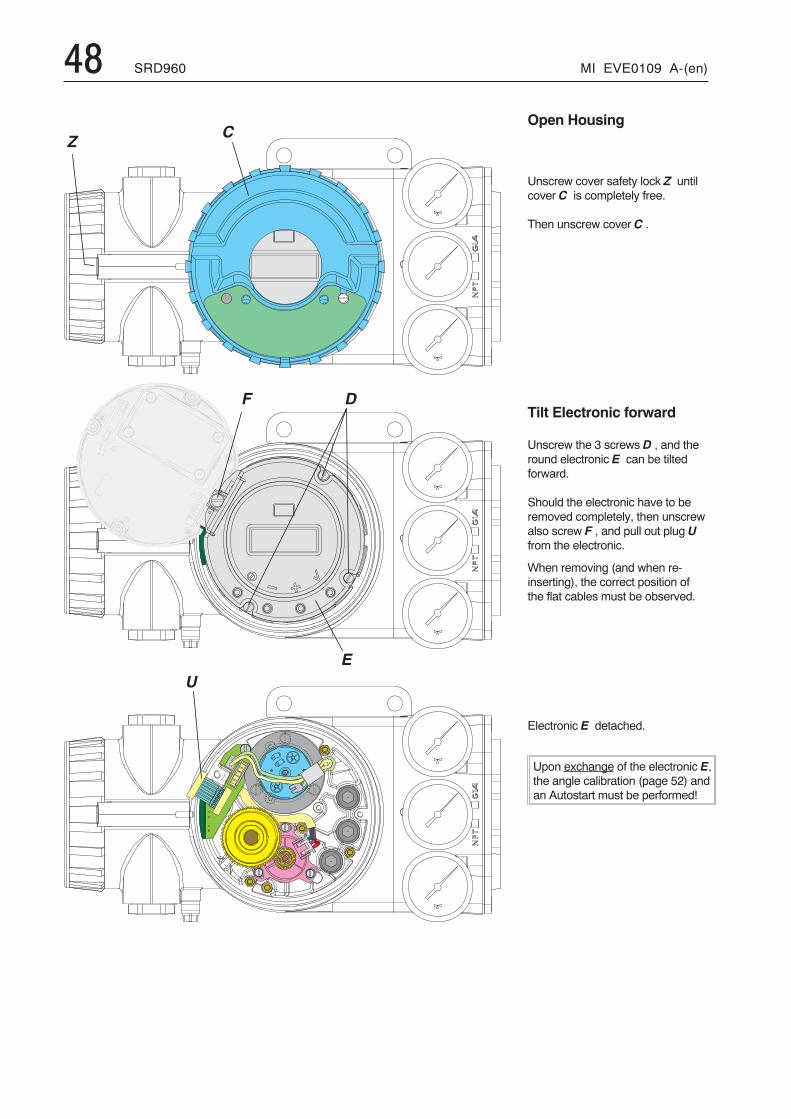
48 SRD960 MI EVE0109 A-(en)
�,
�
�
�
-
Open Housing
Unscrew cover safety lock Z untilcover C is completely free.
Then unscrew cover C .
Tilt Electronic forward
Unscrew the 3 screws D , and theround electronic E can be tiltedforward.
Should the electronic have to beremoved completely, then unscrewalso screw F , and pull out plug Ufrom the electronic.
When removing (and when re-inserting), the correct position ofthe flat cables must be observed.
Electronic E detached.
Upon exchange of the electronic E,the angle calibration (page 52) andan Autostart must be performed!
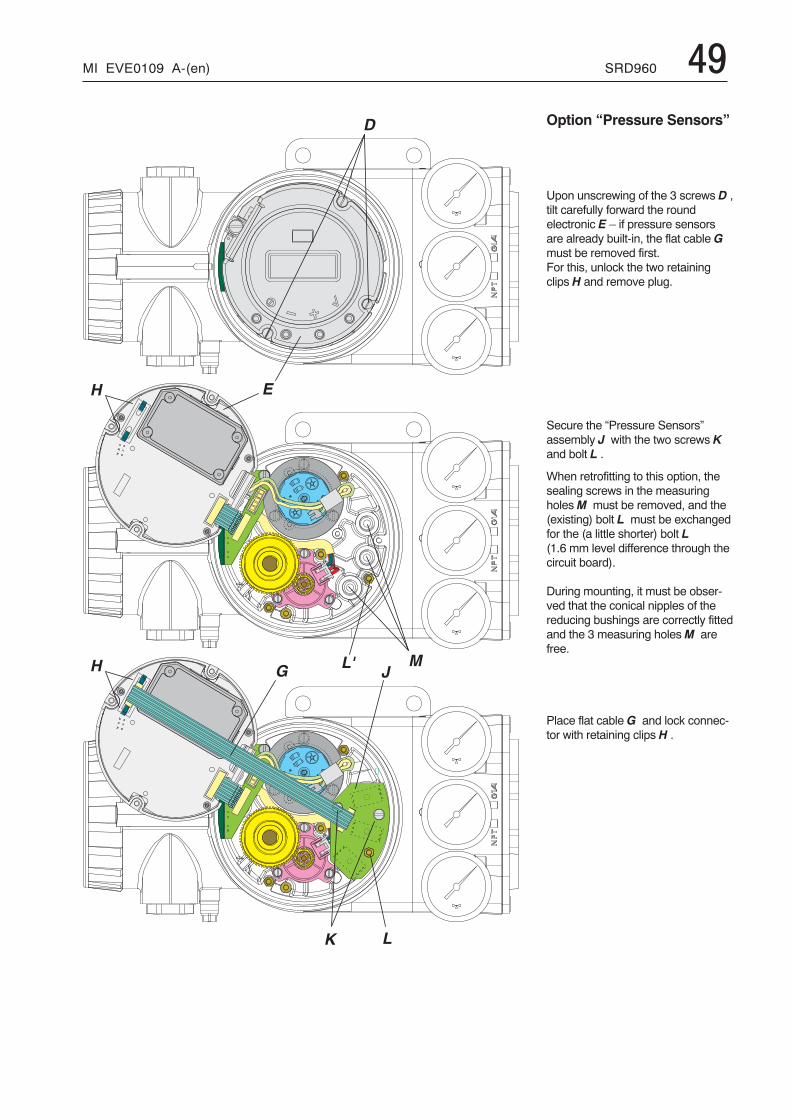
MI EVE0109 A-(en) SRD960 49
�
�
. /
�
$0
� .
� +
Option “Pressure Sensors”
Upon unscrewing of the 3 screws D ,tilt carefully forward the roundelectronic E – if pressure sensorsare already built-in, the flat cable Gmust be removed first.For this, unlock the two retainingclips H and remove plug.
Secure the “Pressure Sensors”assembly J with the two screws Kand bolt L .
When retrofitting to this option, thesealing screws in the measuringholesM must be removed, and the(existing) bolt L must be exchangedfor the (a little shorter) bolt L(1.6 mm level difference through thecircuit board).
During mounting, it must be obser-ved that the conical nipples of thereducing bushings are correctly fittedand the 3 measuring holesM arefree.
Place flat cable G and lock connec-tor with retaining clips H .
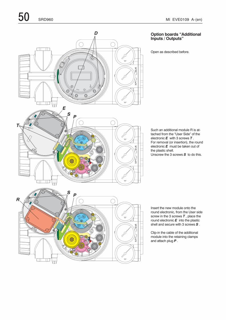
50 SRD960 MI EVE0109 A-(en)
�
1
�)
2
�
�)
Option boards “AdditionalInputs / Outputs”
Open as described before.
Such an additional module R is at-tached from the “User Side” of theelectronic E with 3 screws T .For removal (or insertion), the roundelectronic E must be taken out ofthe plastic shell.Unscrew the 3 screws S to do this.
Insert the new module onto theround electronic, from the User sidescrew in the 3 screws T , place theround electronic E into the plasticshell and secure with 3 screws S .
Clip-in the cable of the additionalmodule into the retaining clampsand attach plug P .
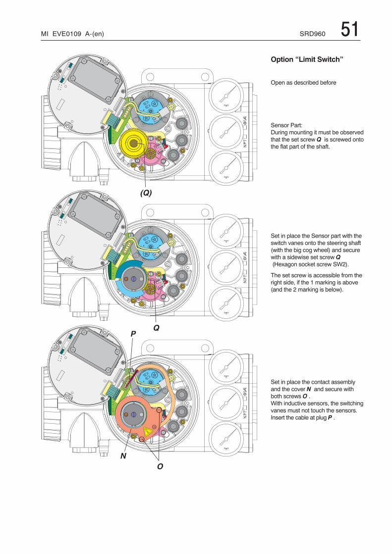
MI EVE0109 A-(en) SRD960 51
)
3
4
5
' 5 (
Option “Limit Switch”
Open as described before
Sensor Part:During mounting it must be observedthat the set screw Q is screwed ontothe flat part of the shaft.
Set in place the Sensor part with theswitch vanes onto the steering shaft(with the big cog wheel) and securewith a sidewise set screw Q(Hexagon socket screw SW2).
The set screw is accessible from theright side, if the 1 marking is above(and the 2 marking is below).
Set in place the contact assemblyand the cover N and secure withboth screws O .With inductive sensors, the switchingvanes must not touch the sensors.Insert the cable at plug P .
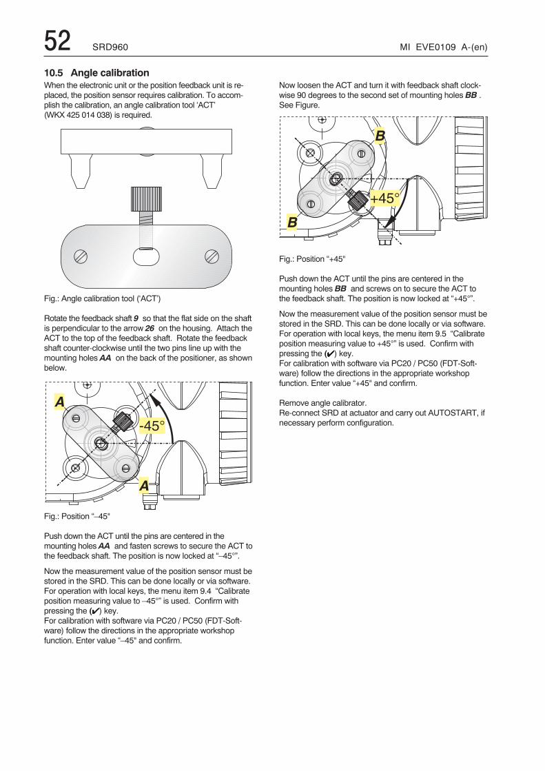
52 SRD960 MI EVE0109 A-(en)
�
�
E � ( L
�
�
� � ( L
10.5 Angle calibrationWhen the electronic unit or the position feedback unit is re-placed, the position sensor requires calibration. To accom-plish the calibration, an angle calibration tool ‘ACT’(WKX 425 014 038) is required.
Fig.: Angle calibration tool (‘ACT’)
Rotate the feedback shaft 9 so that the flat side on the shaftis perpendicular to the arrow 26 on the housing. Attach theACT to the top of the feedback shaft. Rotate the feedbackshaft counter-clockwise until the two pins line up with themounting holes AA on the back of the positioner, as shownbelow.
Fig.: Position “–45"
Push down the ACT until the pins are centered in themounting holes AA and fasten screws to secure the ACT tothe feedback shaft. The position is now locked at “–45°”.
Now the measurement value of the position sensor must bestored in the SRD. This can be done locally or via software.For operation with local keys, the menu item 9.4 “Calibrateposition measuring value to –45°” is used. Confirm withpressing the (�) key.For calibration with software via PC20 / PC50 (FDT-Soft-ware) follow the directions in the appropriate workshopfunction. Enter value “–45" and confirm.
Now loosen the ACT and turn it with feedback shaft clock-wise 90 degrees to the second set of mounting holes BB .See Figure.
Fig.: Position “+45"
Push down the ACT until the pins are centered in themounting holes BB and screws on to secure the ACT tothe feedback shaft. The position is now locked at “+45°”.
Now the measurement value of the position sensor must bestored in the SRD. This can be done locally or via software.For operation with local keys, the menu item 9.5 “Calibrateposition measuring value to +45°” is used. Confirm withpressing the (�) key.For calibration with software via PC20 / PC50 (FDT-Soft-ware) follow the directions in the appropriate workshopfunction. Enter value “+45" and confirm.
Remove angle calibrator.Re-connect SRD at actuator and carry out AUTOSTART, ifnecessary perform configuration.
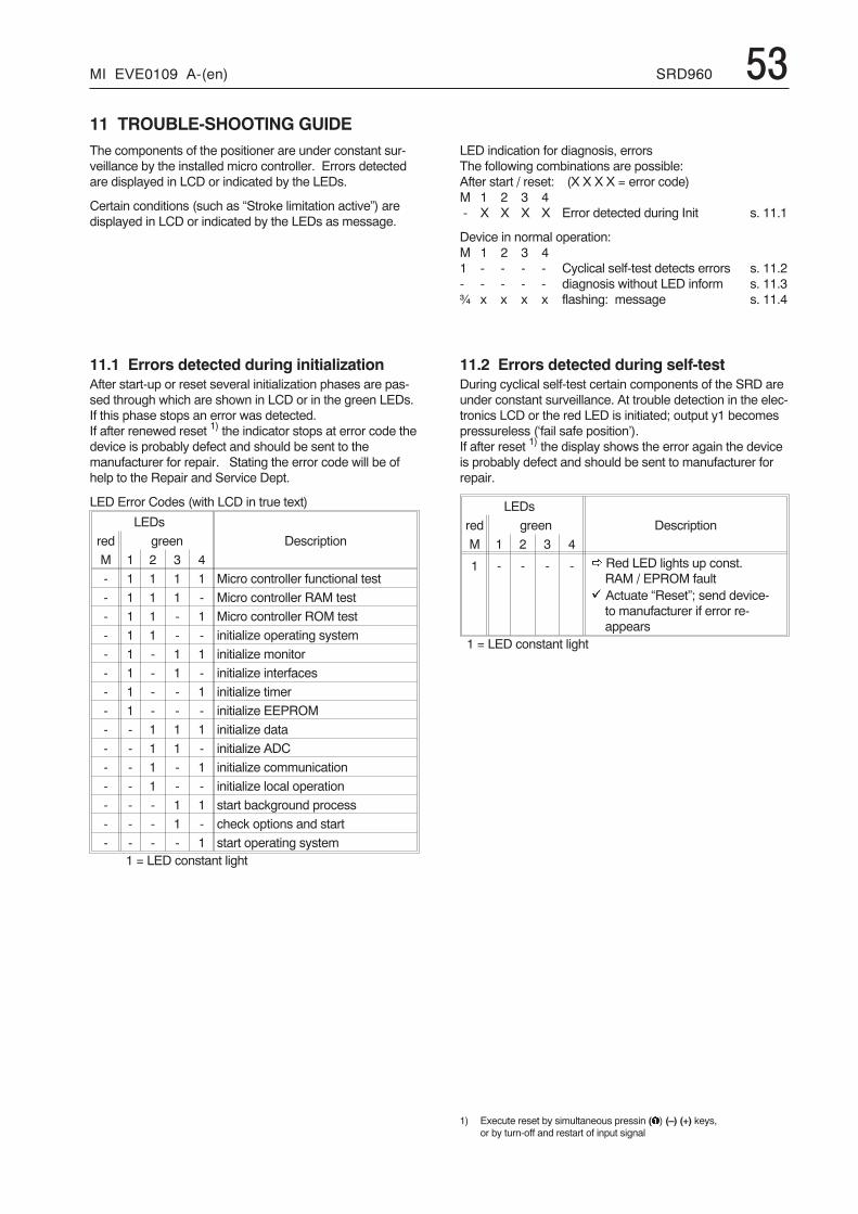
MI EVE0109 A-(en) SRD960 5311 TROUBLE-SHOOTING GUIDEThe components of the positioner are under constant sur-veillance by the installed micro controller. Errors detectedare displayed in LCD or indicated by the LEDs.
Certain conditions (such as “Stroke limitation active”) aredisplayed in LCD or indicated by the LEDs as message.
LED indication for diagnosis, errorsThe following combinations are possible:After start / reset: (X X X X = error code)M 1 2 3 4- X X X X Error detected during Init s. 11.1
Device in normal operation:M 1 2 3 41 - - - - Cyclical self-test detects errors s. 11.2- - - - - diagnosis without LED inform s. 11.3¾ x x x x flashing: message s. 11.4
11.1 Errors detected during initializationAfter start-up or reset several initialization phases are pas-sed through which are shown in LCD or in the green LEDs.If this phase stops an error was detected.If after renewed reset 1) the indicator stops at error code thedevice is probably defect and should be sent to themanufacturer for repair. Stating the error code will be ofhelp to the Repair and Service Dept.
LED Error Codes (with LCD in true text)
LEDs
Descriptionred green
M 1 2 3 4
- 1 1 1 1 Micro controller functional test
- 1 1 1 - Micro controller RAM test
- 1 1 - 1 Micro controller ROM test
- 1 1 - - initialize operating system
- 1 - 1 1 initialize monitor
- 1 - 1 - initialize interfaces
- 1 - - 1 initialize timer
- 1 - - - initialize EEPROM
- - 1 1 1 initialize data
- - 1 1 - initialize ADC
- - 1 - 1 initialize communication
- - 1 - - initialize local operation
- - - 1 1 start background process
- - - 1 - check options and start
- - - - 1 start operating system1 = LED constant light
11.2 Errors detected during self-testDuring cyclical self-test certain components of the SRD areunder constant surveillance. At trouble detection in the elec-tronics LCD or the red LED is initiated; output y1 becomespressureless (‘fail safe position’).If after reset 1) the display shows the error again the deviceis probably defect and should be sent to manufacturer forrepair.
LEDs
Descriptionred green
M 1 2 3 4
1 - - - - � Red LED lights up const.RAM / EPROM fault
� Actuate “Reset”; send device-to manufacturer if error re-appears
1 = LED constant light
1) Execute reset by simultaneous pressin (�) (–) (+) keys,or by turn-off and restart of input signal
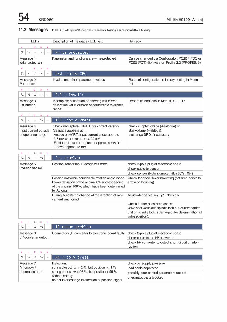
54 SRD960 MI EVE0109 A-(en)
11.3 Messages In the SRD with option “Built-in pressure sensors” flashing is superimposed by a flickering
LEDs Description of message / LCD text Remedy
M 1 2 3 4
¾ ¼ - - - ?���� $�������%
Message 1:write protection
Parameter and functions are write-protected Can be changed via Configurator, PC20 / IFDC orPC50 (FDT)-Software or Profile 3.0 (PROFIBUS)
M 1 2 3 4
¾ - ¼ - - C�% ���)� �
Message 2:Parameter
Invalid, undefined parameter values Reset of configuration to factory setting in Menu9.1
M 1 2 3 4
¾ ¼ ¼ - - ���1 ������%
Message 3:Calibration
Incomplete calibration or entering value resp.calibration value outside of permissible tolerancerange
Repeat calibrations in Menus 9.2 ... 9.5
M 1 2 3 4
¾ - - ¼ - '�� ���$ ������
Message 4:Input current outsideof operating range
Check nameplate (INPUT) for correct versionMessage appears at :Analog or HART: input current under approx.3.8 mA or above approx. 22 mAFieldbus: input current under approx. 9 mA orabove approx. 12 mA
check supply voltage (Analogue) orBus voltage (Fieldbus),exchange SRD if necessary
M 1 2 3 4
¾ ¼ - ¼ - 3�� $��1��#
Message 5:Position sensor
Position sensor input recognizes error check 3-pole plug at electronic boardcheck cable to sensorcheck sensor (Potentiometer: 5k +20% –0%)
Position not within permissible rotation angle range.Lower deviation of the original 0% and exceedingof the original 100%, which have been determinedby Autostart.
Check feedback lever mounting (flat area points toarrow on housing)
During Autostart a change of the direction of mo-vement was found
Acknowledge via key (�) , then o.k.
Check further possible reasons:valve seat worn-out; spindle lock out-of-line; carrierunit on spindle lock is damaged (for determination ofvalve position).
M 1 2 3 4
¾ - ¼ ¼ - '3 #���� $��1��#
Message 6:I/P-converter output
Connection I/P converter to electronic board faulty check 2-pole plug at electronic boardcheck cable to the I/P convertercheck I/P converter to detect short circuit or inter-ruption
M 1 2 3 4
¾ ¼ ¼ ¼ - "� �$$�( $����
Message 7:Air supply /pneumatic error
Detection:spring closes: w > 2 %, but position < 1 %spring opens: w < 98 %, but position > 99 %without spring:no actuator change in direction of position signal
check air supply pressurelead cable separatedpossibly poor control parameters are setpneumatic parts blocked
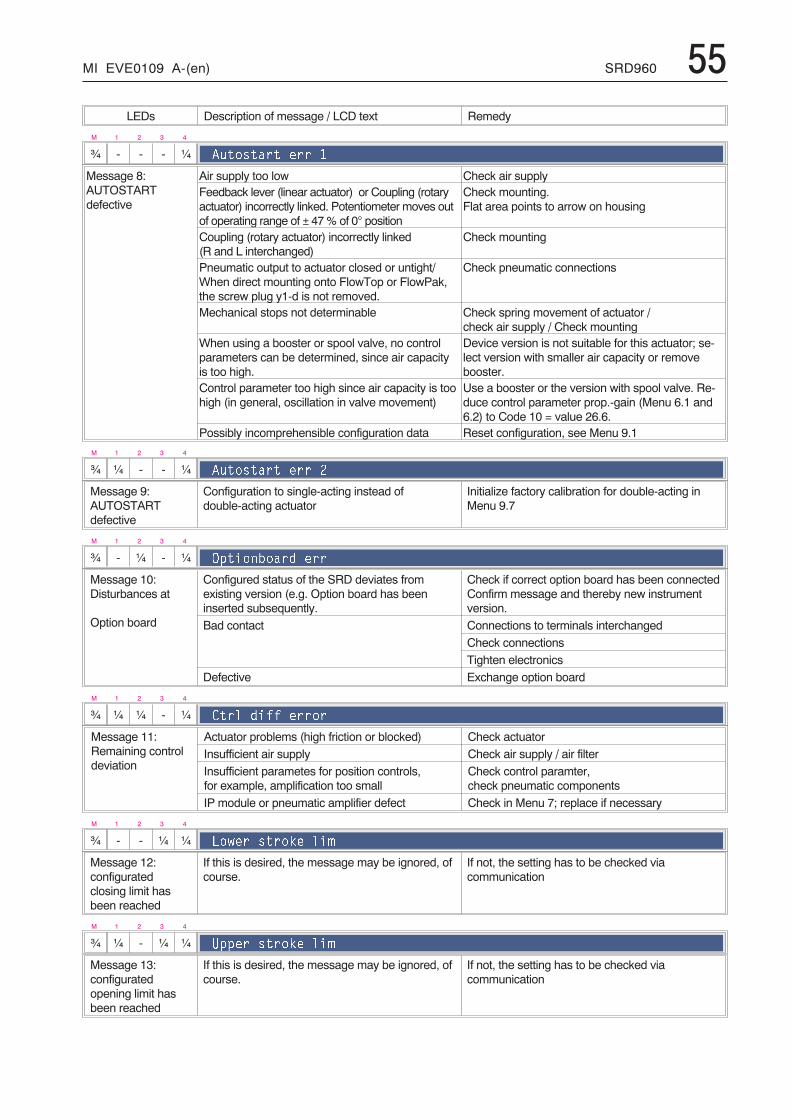
MI EVE0109 A-(en) SRD960 55LEDs Description of message / LCD text Remedy
M 1 2 3 4
¾ - - - ¼ �������� ���
Message 8:AUTOSTARTdefective
Air supply too low Check air supplyFeedback lever (linear actuator) or Coupling (rotaryactuator) incorrectly linked. Potentiometer moves outof operating range of ± 47% of 0° position
Check mounting.Flat area points to arrow on housing
Coupling (rotary actuator) incorrectly linked(R and L interchanged)
Check mounting
Pneumatic output to actuator closed or untight/When direct mounting onto FlowTop or FlowPak,the screw plug y1-d is not removed.
Check pneumatic connections
Mechanical stops not determinable Check spring movement of actuator /check air supply / Check mounting
When using a booster or spool valve, no controlparameters can be determined, since air capacityis too high.
Device version is not suitable for this actuator; se-lect version with smaller air capacity or removebooster.
Control parameter too high since air capacity is toohigh (in general, oscillation in valve movement)
Use a booster or the version with spool valve. Re-duce control parameter prop.-gain (Menu 6.1 and6.2) to Code 10 = value 26.6.
Possibly incomprehensible configuration data Reset configuration, see Menu 9.1
M 1 2 3 4
¾ ¼ - - ¼ �������� ��� �
Message 9:AUTOSTARTdefective
Configuration to single-acting instead ofdouble-acting actuator
Initialize factory calibration for double-acting inMenu 9.7
M 1 2 3 4
¾ - ¼ - ¼ !$����1���% ���
Message 10:Disturbances at
Option board
Configured status of the SRD deviates fromexisting version (e.g. Option board has beeninserted subsequently.
Check if correct option board has been connectedConfirm message and thereby new instrumentversion.
Bad contact Connections to terminals interchangedCheck connectionsTighten electronics
Defective Exchange option board
M 1 2 3 4
¾ ¼ ¼ - ¼ ��� %�)) �����
Message 11:Remaining controldeviation
Actuator problems (high friction or blocked) Check actuatorInsufficient air supply Check air supply / air filterInsufficient parametes for position controls,for example, amplification too small
Check control paramter,check pneumatic components
IP module or pneumatic amplifier defect Check in Menu 7; replace if necessary
M 1 2 3 4
¾ - - ¼ ¼ ��+�� ����*� ��#
Message 12:configuratedclosing limit hasbeen reached
If this is desired, the message may be ignored, ofcourse.
If not, the setting has to be checked viacommunication
M 1 2 3 4
¾ ¼ - ¼ ¼ 9$$�� ����*� ��#
Message 13:configuratedopening limit hasbeen reached
If this is desired, the message may be ignored, ofcourse.
If not, the setting has to be checked viacommunication

56 SRD960 MI EVE0109 A-(en)
LEDs Description of message / LCD text Remedy
M 1 2 3 4
¾ - ¼ ¼ ¼ ������������
Message 14:Maintenancerequired
Operating point of controller is outside ofpermissible tolerance
Pneumatic components have to be checked and ifnecessary readjusted. Filters are possibly blockedand have to be replaced
M 1 2 3 4
¾ ¼ ¼ ¼ ¼ 9�)�������
Message 15: Not defined
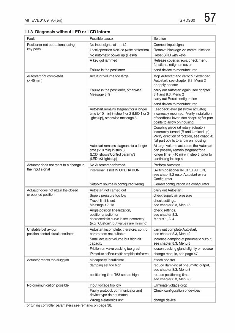
MI EVE0109 A-(en) SRD960 5711.3 Diagnosis without LED or LCD informFault Possible cause Solution
Positioner not operational usingkey pads
No input signal at 11, 12 Connect input signal
Local operation blocked (write protection) Remove blockage via communication
No automatic power up (Reset) Reset SRD with keys
A key got jammed Release cover screws, check menufunctions, retighten cover
Failure in the positioner send device to manufacturer
Autostart not completed(> 45 min)
Actuator volume too large stop Autostart and carry out extendedAutostart, see chapter 8.3, Menü 2or apply booster
Failure in the positioner, otherwiseMessage 8, 9
carry out Autostart again, see chapter.8.1 and 8.3, Menu 2carry out Reset configuration
send device to manufacturer
Autostart remains stagnant for a longertime (>10 min) in step 1 or 2 (LED 1 or 2lights up), otherwise message 8
Feedback lever (at stroke actuator)incorrectly mounted. Verify installationof feedback lever, see chapt. 4; flat partpoints to arrow on housing
Coupling piece (at rotary actuator)incorrectly turned (R and L mixed up):Verify direction of rotation, see chapt. 4;flat part points to arrow on housing
Autostart remains stagnant for a longertime (>10 min) in step 3(LCD: shows”Control params“)(LED: #3 lights up)
At large volume actuators the Autostartcan possibly remain stagnant for alonger time (>10 min) in step 3, prior tocontinuing in step 4
Actuator does not react to a change inthe input signal
No Autostart performed. Perform Autostart.
Positioner is not IN OPERATION Switch positioner IN OPERATION,see chap. 8.2 resp. Autostart or viaConfigurator
Setpoint source is configured wrong Correct configuration via configurator
Actuator does not attain the closedor opened position
Autostart not carried out carry out Autostart
Supply pressure too low check supply air pressure
Travel limit is setMessage 12, 13
check settings,see chapter 8.3, Menu 5
Angle position linearization,positioner action orcharacteristic curve is set incorrectly(e.g. ‘Custom’, but values are missing)
check settings,see chapter 8.3,Menus 1, 3, 4
Unstable behaviour,position control circuit oscillates
Autostart incomplete, therefore, controlparameters not suitable
carry out complete Autostart,see chapter 8.3, Menu 2
Small actuator volume but high aircapacity
increase damping at pneumatic output,see chapter 8.3, Menu 8
Friction on valve packing too great loosen packing gland slightly or replace
IPmodule orPneumatic amplifier defective change module, see page 47
Actuator reacts too sluggish air capacity insufficient attach booster
damping set too high reduce damping at pneumatic output,see chapter 8.3, Menu 8
positioning time T63 set too high reduce positioning time,see chapter 8.3, Menu 6
No communication possible Input voltage too low Eliminate voltage drop
Faulty protocol, communicator anddevice type do not match
Check configuration of devices
Wrong elektronics unit change device
For tuning controller parameters see remarks on page 38.
58 SRD960 MI EVE0109 A-(en)
13 SYSTEM CONFIGURATIONThe safety requirements must be observed!
13.1 HART CommunicationWhen using the ‘communication’ (an alternating currentsignal, which is modulated onto the 4-20 mA signal), it mustbe observed that the connected outputs are suitable for theused frequency ranges. Apart from the load, also the alter-nating current impedances have to be observed.It is recommended therefore, to use only suitable instru-ments.
To eliminate crosstalk between leads and to reduce distur-bances through electromagnetic influences, it is recommen-ded to use twisted paired shielded leads (0,3...2,5 mm2,max. 100 pF/m).
The capacities of the leads and the connected instrumentsmust not exceed the maximum values for HART.
All components which are connected to the SRD in anexplosion hazardous area, require an Ex-Approval. Thetherein applicable limit values must not be exceeded in anycase. These limit values also have to be adhered to whenconnecting additional capacitances, inductances, voltagesand currents.
Measuring HART Communication SignalIf a reliable communication signal can not be received, it isadvisable to check the level with an oscilloscope. The firstdata block always comes from the configurator and the se-cond block is the reply from the SRD.
HART measured atconfigurator:
measured atSRD:
Configuratortransmits
at least350 mVpp
at least120 mVpp
SRD960transmits
at least120 mVpp
at least400 mVpp
12 SAFETY REQUIREMENTS
12.1 EMC and CEFor notes regarding Electromagnetic compatibility EMC andCE labels see Product Specifications Sheet PSS EVE0109 A.
In order to ensure EMC protection, the screwed electronicshousing must be locked.
12.2 Explosion protection(Only if ordered)
Technical data for explosion protection see Product Specifi-cations Sheet PSS EVE0109 A or Certificates of Confor-mity EX EVE0109 A.
For installations located in explosive atmospheres, all rele-vant national regulations and installation conditions must beobserved, e.g. in the Federal Republic of Germany ElexVand DIN VDE 0165.
Attention:When repairing explosion-protected equipment, observethe national regulations.
Repairs involving parts must be manufacturer’s originalparts.
The following applies to the Federal Republic of Germany:Repairs involving parts required for explosion protectionmust either be carried out by the manufacturer or by autho-rized personnel and confirmed by certificate.
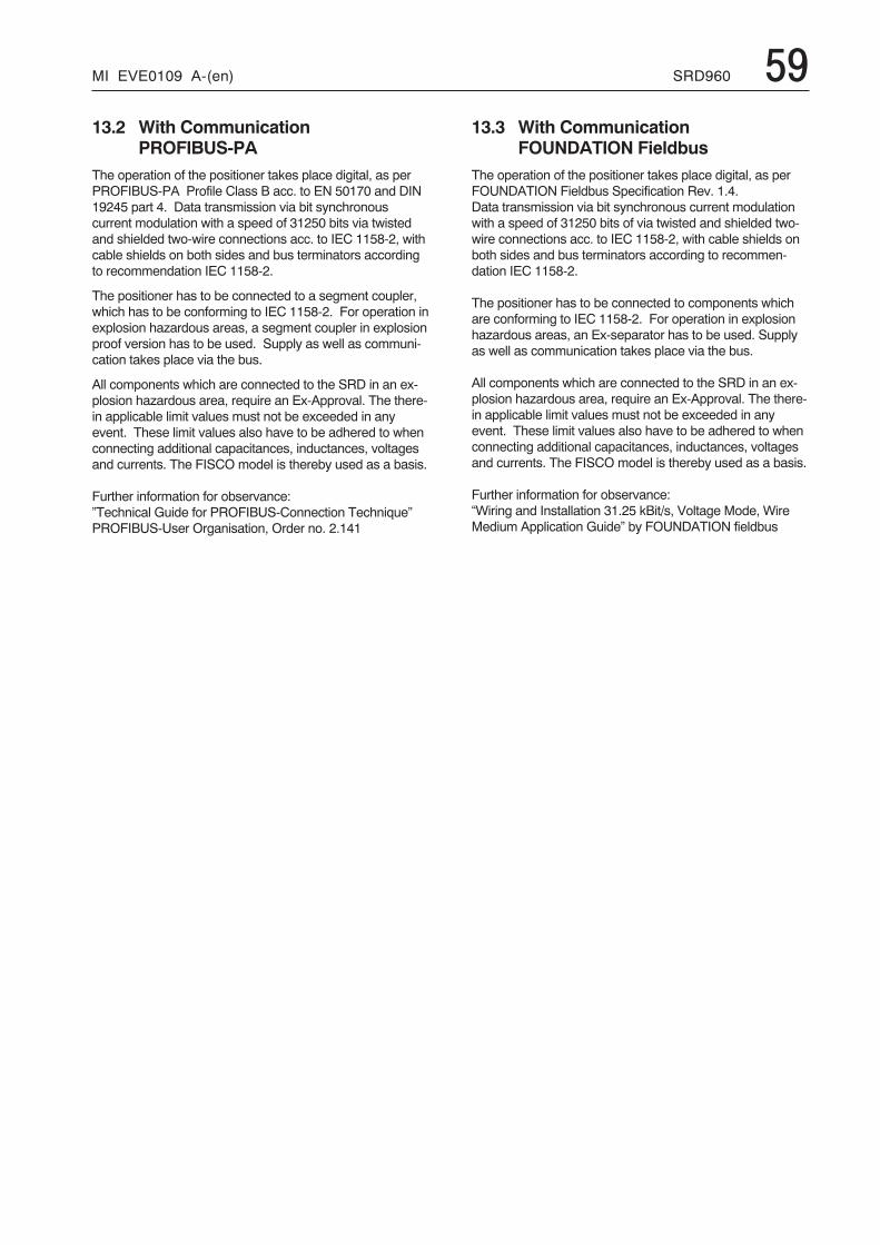
MI EVE0109 A-(en) SRD960 5913.2 With Communication
PROFIBUS-PAThe operation of the positioner takes place digital, as perPROFIBUS-PA Profile Class B acc. to EN 50170 and DIN19245 part 4. Data transmission via bit synchronouscurrent modulation with a speed of 31250 bits via twistedand shielded two-wire connections acc. to IEC 1158-2, withcable shields on both sides and bus terminators accordingto recommendation IEC 1158-2.
The positioner has to be connected to a segment coupler,which has to be conforming to IEC 1158-2. For operation inexplosion hazardous areas, a segment coupler in explosionproof version has to be used. Supply as well as communi-cation takes place via the bus.
All components which are connected to the SRD in an ex-plosion hazardous area, require an Ex-Approval. The there-in applicable limit values must not be exceeded in anyevent. These limit values also have to be adhered to whenconnecting additional capacitances, inductances, voltagesand currents. The FISCO model is thereby used as a basis.
Further information for observance:”Technical Guide for PROFIBUS-Connection Technique”PROFIBUS-User Organisation, Order no. 2.141
13.3 With CommunicationFOUNDATION Fieldbus
The operation of the positioner takes place digital, as perFOUNDATION Fieldbus Specification Rev. 1.4.Data transmission via bit synchronous current modulationwith a speed of 31250 bits of via twisted and shielded two-wire connections acc. to IEC 1158-2, with cable shields onboth sides and bus terminators according to recommen-dation IEC 1158-2.
The positioner has to be connected to components whichare conforming to IEC 1158-2. For operation in explosionhazardous areas, an Ex-separator has to be used. Supplyas well as communication takes place via the bus.
All components which are connected to the SRD in an ex-plosion hazardous area, require an Ex-Approval. The there-in applicable limit values must not be exceeded in anyevent. These limit values also have to be adhered to whenconnecting additional capacitances, inductances, voltagesand currents. The FISCO model is thereby used as a basis.
Further information for observance:“Wiring and Installation 31.25 kBit/s, Voltage Mode, WireMedium Application Guide” by FOUNDATION fieldbus
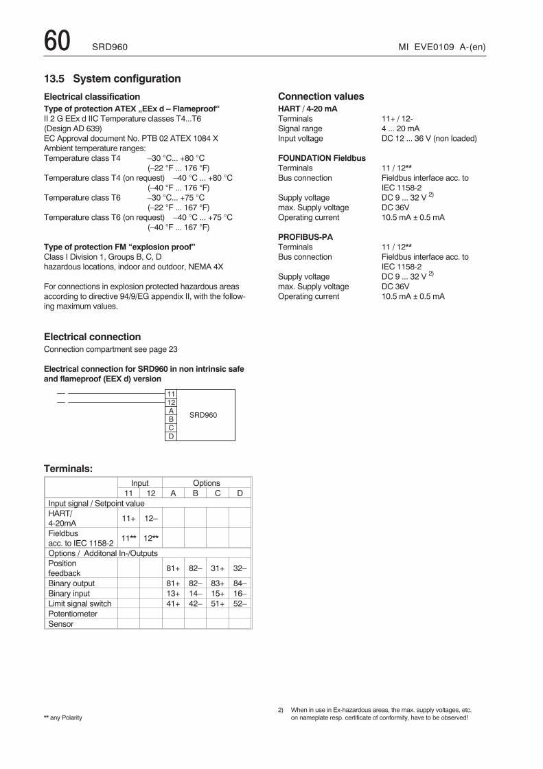
60 SRD960 MI EVE0109 A-(en)
� �� 24 �
� � � �
13.5 System configuration
Electrical classificationType of protection ATEX „EEx d – Flameproof“II 2 G EEx d IIC Temperature classes T4...T6(Design AD 639)EC Approval document No. PTB 02 ATEX 1084 XAmbient temperature ranges:Temperature class T4 –30 °C... +80 °C
(–22 °F ... 176 °F)Temperature class T4 (on request) –40 °C ... +80 °C
(–40 °F ... 176 °F)Temperature class T6 –30 °C... +75 °C
(–22 °F ... 167 °F)Temperature class T6 (on request) –40 °C ... +75 °C
(–40 °F ... 167 °F)
Type of protection FM “explosion proof”Class I Division 1, Groups B, C, Dhazardous locations, indoor and outdoor, NEMA 4X
For connections in explosion protected hazardous areasaccording to directive 94/9/EG appendix II, with the follow-ing maximum values.
Electrical connectionConnection compartment see page 23
Electrical connection for SRD960 in non intrinsic safeand flameproof (EEX d) version
Terminals:Input Options
11 12 A B C DInput signal / Setpoint valueHART/4-20mA
11+ 12–
Fieldbusacc. to IEC 1158-2
11** 12**
Options / Additonal In-/OutputsPositionfeedback
81+ 82– 31+ 32–
Binary output 81+ 82– 83+ 84–Binary input 13+ 14– 15+ 16–Limit signal switch 41+ 42– 51+ 52–PotentiometerSensor
** any Polarity
Connection valuesHART / 4-20 mATerminals 11+ / 12-Signal range 4 ... 20 mAInput voltage DC 12 ... 36 V (non loaded)
FOUNDATION FieldbusTerminals 11 / 12**Bus connection Fieldbus interface acc. to
IEC 1158-2Supply voltage DC 9 ... 32 V 2)
max. Supply voltage DC 36VOperating current 10.5 mA ± 0.5 mA
PROFIBUS-PATerminals 11 / 12**Bus connection Fieldbus interface acc. to
IEC 1158-2Supply voltage DC 9 ... 32 V 2)
max. Supply voltage DC 36VOperating current 10.5 mA ± 0.5 mA
2) When in use in Ex-hazardous areas, the max. supply voltages, etc.on nameplate resp. certificate of conformity, have to be observed!
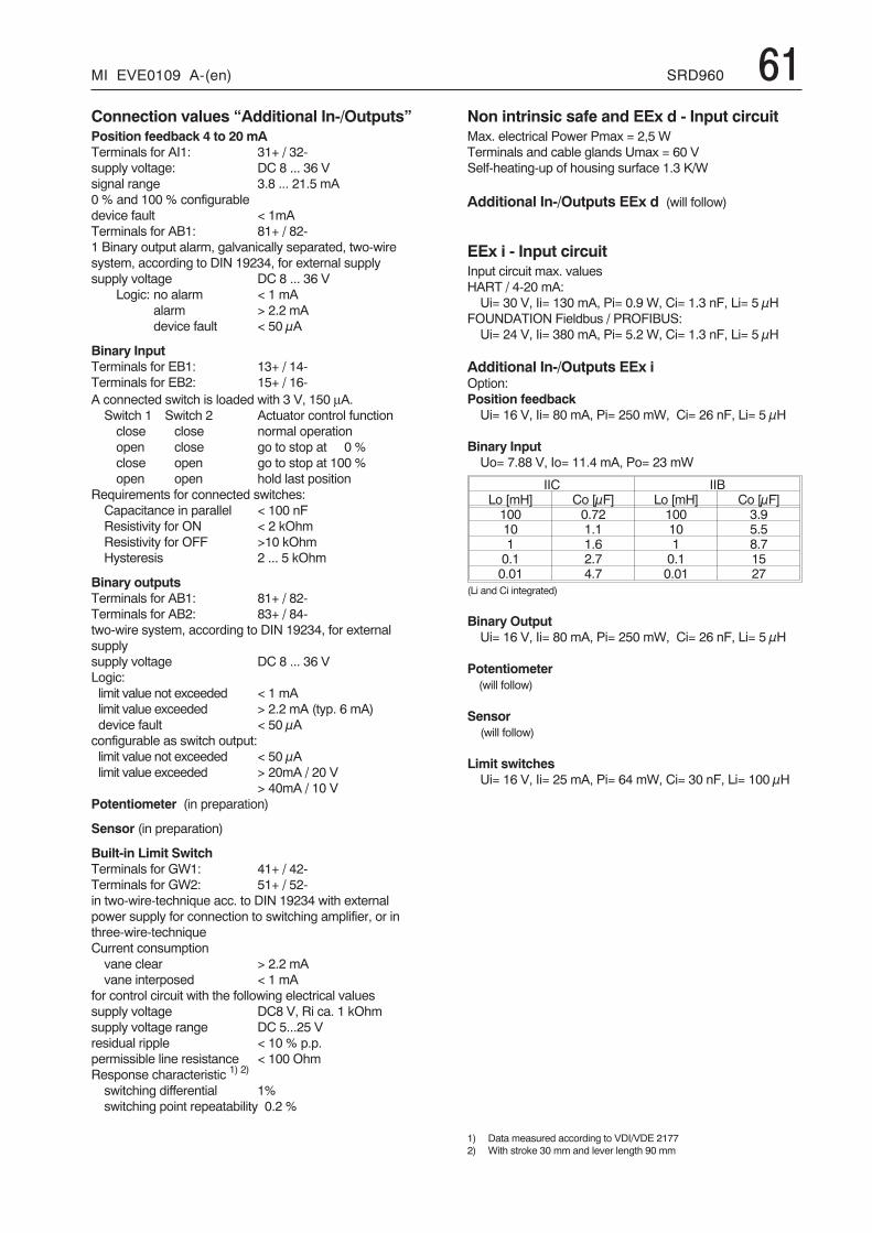
MI EVE0109 A-(en) SRD960 61Connection values “Additional In-/Outputs”Position feedback 4 to 20 mATerminals for AI1: 31+ / 32-supply voltage: DC 8 ... 36 Vsignal range 3.8 ... 21.5 mA0 % and 100 % configurabledevice fault < 1mATerminals for AB1: 81+ / 82-1 Binary output alarm, galvanically separated, two-wiresystem, according to DIN 19234, for external supplysupply voltage DC 8 ... 36 V
Logic: no alarm < 1 mAalarm > 2.2 mAdevice fault < 50 μA
Binary InputTerminals for EB1: 13+ / 14-Terminals for EB2: 15+ / 16-A connected switch is loaded with 3 V, 150 μA.Switch 1 Switch 2 Actuator control functionclose close normal operationopen close go to stop at 0 %close open go to stop at 100 %open open hold last position
Requirements for connected switches:Capacitance in parallel < 100 nFResistivity for ON < 2 kOhmResistivity for OFF >10 kOhmHysteresis 2 ... 5 kOhm
Binary outputsTerminals for AB1: 81+ / 82-Terminals for AB2: 83+ / 84-two-wire system, according to DIN 19234, for externalsupplysupply voltage DC 8 ... 36 VLogic:limit value not exceeded < 1 mAlimit value exceeded > 2.2 mA (typ. 6 mA)device fault < 50 μAconfigurable as switch output:limit value not exceeded < 50 μAlimit value exceeded > 20mA / 20 V
> 40mA / 10 VPotentiometer (in preparation)
Sensor (in preparation)
Built-in Limit SwitchTerminals for GW1: 41+ / 42-Terminals for GW2: 51+ / 52-in two-wire-technique acc. to DIN 19234 with externalpower supply for connection to switching amplifier, or inthree-wire-techniqueCurrent consumptionvane clear > 2.2 mAvane interposed < 1 mA
for control circuit with the following electrical valuessupply voltage DC8 V, Ri ca. 1 kOhmsupply voltage range DC 5...25 Vresidual ripple < 10 % p.p.permissible line resistance < 100 OhmResponse characteristic 1) 2)
switching differential 1%switching point repeatability 0.2 %
Non intrinsic safe and EEx d - Input circuitMax. electrical Power Pmax = 2,5 WTerminals and cable glands Umax = 60 VSelf-heating-up of housing surface 1.3 K/W
Additional In-/Outputs EEx d (will follow)
EEx i - Input circuitInput circuit max. valuesHART / 4-20 mA:Ui= 30 V, Ii= 130 mA, Pi= 0.9 W, Ci= 1.3 nF, Li= 5 μH
FOUNDATION Fieldbus / PROFIBUS:Ui= 24 V, Ii= 380 mA, Pi= 5.2 W, Ci= 1.3 nF, Li= 5 μH
Additional In-/Outputs EEx iOption:Position feedbackUi= 16 V, Ii= 80 mA, Pi= 250 mW, Ci= 26 nF, Li= 5 μH
Binary InputUo= 7.88 V, Io= 11.4 mA, Po= 23 mW
IIC IIBLo [mH] Co [μF] Lo [mH] Co [μF]100 0.72 100 3.910 1.1 10 5.51 1.6 1 8.70.1 2.7 0.1 150.01 4.7 0.01 27
(Li and Ci integrated)
Binary OutputUi= 16 V, Ii= 80 mA, Pi= 250 mW, Ci= 26 nF, Li= 5 μH
Potentiometer(will follow)
Sensor(will follow)
Limit switchesUi= 16 V, Ii= 25 mA, Pi= 64 mW, Ci= 30 nF, Li= 100 μH
1) Data measured according to VDI/VDE 21772) With stroke 30 mm and lever length 90 mm
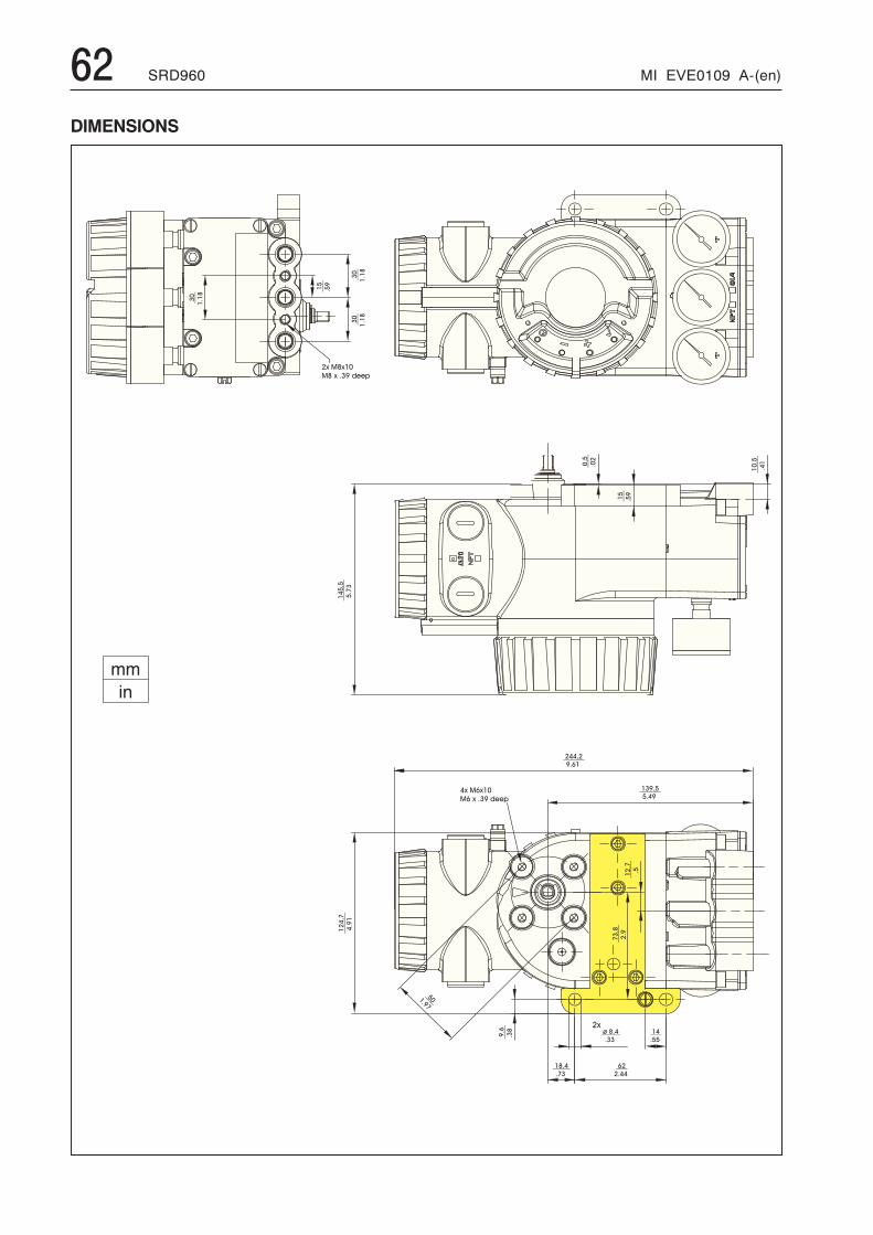
62 SRD960 MI EVE0109 A-(en)
DIMENSIONS
����
����
����
��
����
����
����
����
� � � � � � �
� � � � � � � � � � �
�������
����
�����
��
����
��
������
���
� � � � �
� � �
� � � � � � � �
� � � � � � � � � � �
������
���
� � � � � �
� � �
� � � �
� � �
� � � �� � �
� � � � � � �
� � �
�
� � �
� � �
� � � � � �
� � �
����
���
������
�
�����
��
� �� �
MI EVE0109 A-(en) SRD960 63
Additional Documentation for this product:Technical Information of Attachment Kits for PositionersTI EVE0011 A Overview of Attachment Kits of all positioners on actuators/valves of different manufacturersQuick GuideQG EVE0109 A Extract of Master Instruction for an easy to use, easy understandable and fast start-up.
This document highlights the most important.Master Instructions:MI EVE0109 A SRD960 -All Versions -Technical Information for Fieldbus-Communication:TI EVE0109 P SRD991/960 -PROFIBUS-PATI EVE0109 Q SRD991/960 -FOUNDATION Fieldbus H1Master Instruction for HART-Communication:MI EVE0109 B HART with Hand-Held TerminalMaster Instruction for configuration- and operation-software PC20and integration into Foxboro I/A Series System:MI 020-495 HART / PROFIBUS-PA and IRCOM with PC by means of PC20/ IFDCB 0193 VH I/A Series System
Additional Documentation for other products:Specifications devicePSS EVE0101 SRP981 Pneumatic PositionerPSS EVE0102 SRI986 Electro-Pneumatic PositionerPSS EVE0103 SRI983 Electro-Pneumatic Positioner- explosion proof or EEx d versionPSS EVE0105 SRD991 Intelligent PositionerPSS EVE0107 SRI990 Analog PositionerPSS EVE0109 SRD960 Universal PositionerPSS EMO0100 Accessories for devices with HART Protocol

64 SRD960 MI EVE0109 A-(en)
Subject to alterations - reprinting, copying and translation prohibited. Products and publications are normally quotedhere without reference to existing patents, registered utility models or trademarks. The lack of any such referencedoes not justify the assumption that a product or symbol is free.
FOXBOROECKARDTGmbH ECKARDTS.A.S. DOKT533 495 144Pragstr. 82 20 rue de la MarneD-70376 Stuttgart F-68360 SoultzGermany FranceTel. +49 (0)711 502-0 Tel. + 33 (0)3 89 62 15 30Fax +49 (0)711 502-597 Fax + 33 (0)3 89 62 14 85http://www.foxboro-eckardt.com