united states department of agriculture forest service ... · pdf fileunited states department...
TRANSCRIPT
1
September 1999
2300
Technology &Development Program
United States Department of Agriculture
Forest Service
9923 1304—SDTDC
RecreationManagement
TechTipsSANITARY, FROST FREE, ACCESSIBLE HYDRANTS
byLois P. Sicking, Mechanical Engineer
INTRODUCTION AND SCOPEHydrants are used by the public to access water at mostForest Service recreation site facilities. In recent yearsnew sanitary regulations have been established regardingbackflow prevention of hydrants and hose bibs. Hydrantslocated outdoors are susceptible to damage from freezingconditions. The passage of the Americans with DisabilitiesAct (ADA) was a call to action to provide universalaccess.
The project goal was to provide information to the fieldon the performance of commercially available sanitary,frost free, accessible hydrants. This information has beendeveloped for use by the field during procurement,selection, installation, and field testing of hydrants andbackflow prevention devices. Consequently, there is apotential for considerable cost savings.
The objective of this project was to interact withmanufacturers to develop a new hydrant or modify anexisting hydrant to be accessible, sanitary and frost free.No hydrants were available commercially that met allcriteria.
BACKGROUNDConditions could exist at Forest Service recreation sitefacilities, where contaminated water may inadvertentlybe introduced to the water supply. If a garden hoseconnected to a hose bib or hydrant is used to cleanlavatories or toilets, contaminated water could back flowinto the hose. In addition, backflow can occur when thesupply line pressure drops below the head water pressurein the hose. This pressure drop can occur if the waterpressure in the supply line drops due to increased usageor if the end of the hose is elevated higher than the supplyline. With the change in elevation, there is a correspondingchange in head pressure and at a certain height, the waterwill backflow, especially when the supply side is shut off.
This method of cleaning lavatories and toilets is a commonpractice in Forest Service recreation site facilities.
DESIGN CRITERIAThe following design criteria were developed by SanDimas Technology and Development Center (SDTDC)for frost free, sanitary, accessible hydrants for use inForest Service recreation site facilities:
· Controls activated with a maximum 5pound force (22 N)
· Backflow prevention mechanism
· Frost free
· Self closing
· Designed to allow field testing to determine ifthe back flow prevention device is functional
· Hydrant functional at a supply line pressure aslow as 20 psig ( 138 kPag)
CURRENT TECHNOLOGYA commercial marketplace search was conducted basedon the design criteria developed. There was nocommercially available hydrant that met all designcriteria. Hydrant manufacturers were encouraged todevelop a prototype based on design criteria. WoodfordManufacturing Company and Murdock Companydeveloped prototypes with a maximum 5 pound force(22 N) to activate controls, backflow prevention, frostfree and self closing. These prototypes were also designedto allow field testing to determine if the backflowprevention device was operational.
PRODUCT TESTINGTesting was conducted by SDTDC on both prototypes.All testing was conducted with the water supply linepressure at 20 psig (138 kPag) and at increments of 10psig (69 kPag) up to 60 psig (414 kPag). Both modelsperformed well in the indicated pressure range and metall design criteria. These two hydrants are the Murdock,Inc. Model Number BFH-M92-FS and WoodfordManufacturing Company Model Number S4H.
For Additional Information Contact: Program Leader, Recreation Management, San Dimas Technology & Development Center,444 East Bonita Avenue, San Dimas CA 91773-3198; Phone 909-599-1267; TDD: 909-599-2357; FAX: 909-592-2309IBM: Mailroom/wo,sdtdc FS web: http://fsweb.sdtdc.wo.fs.fed.us Email: Mailroom/[email protected]
2
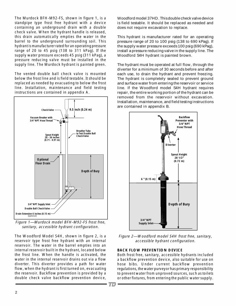
Woodford model 37HD. This double check valve deviceis field testable. It should be replaced as needed anddoes not require excavation to replace.
This hydrant is manufacturer rated for an operatingpressure range of 20 to 100 psig (138 to 690 kPag). Ifthe supply water pressure exceeds 100 psig (690 kPag),install a pressure reducing valve in the supply line. TheWoodford S4H hydrant is painted brown.
The hydrant must be operated at full flow, through thediverter for a minimum of 30 seconds before and aftereach use, to drain the hydrant and prevent freezing.The hydrant is completely sealed to prevent groundand surface water from entering the reservoir or serviceline. If the Woodford model S4H hydrant requiresrepair, the entire working portion of the hydrant can beremoved from the reservoir without excavation.Installation, maintenance, and field testing instructionsare contained in appendix B.
Figure 2—Woodford model S4H frost free, sanitary,accessible hydrant configuration.
BACK FLOW PREVENTION DEVICEBoth frost free, sanitary, accessible hydrants includeda backflow prevention device, also suitable for use onhose bibs. Under current backflow preventionregulations, the water purveyor has primary responsibilityto prevent water from unproved sources, such as toiletsor other fixtures, from entering the public water supply.
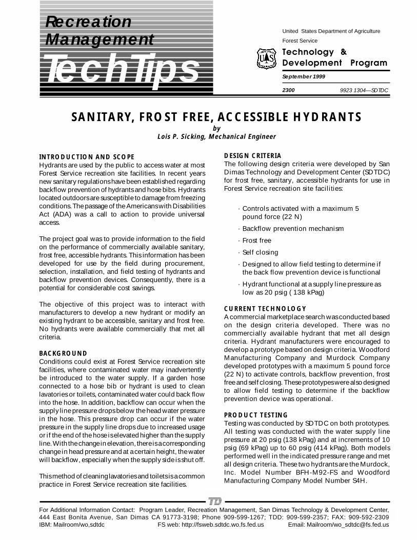
The Murdock BFH-M92-FS, shown in figure 1, is astandpipe type frost free hydrant with a devicecontaining an underground drain with a doublecheck valve. When the hydrant handle is released,this drain automatically empties the water in thebarrel to the underground surrounding soil. Thishydrant is manufacturer rated for an operating pressurerange of 20 to 45 psig (138 to 311 kPag). If thesupply water pressure exceeds 45 psig (311 kPag), apressure reducing valve must be installed in thesupply line. The Murdock hydrant is painted green.
The vented double ball check valve is mountedbelow the frost line and is field testable. It should bereplaced as needed by evacuating to below the frostline. Installation, maintenance and field testinginstructions are contained in appendix A.
Figure 1—Murdock model BFH-M92-FS frost free,sanitary, accessible hydrant configuration.
The Woodford Model S4H, shown in figure 2, is areservoir type frost free hydrant with an internalreservoir. The water in the barrel empties into aninternal reservoir built in the hydrant, located belowthe frost line. When the handle is activated, thewater in the internal reservoir drains out via a flowdiverter. This diverter provides a path for waterflow, when the hydrant is first turned on, evacuatingthe reservoir. Backflow prevention is provided by adouble check valve backflow prevention device,
9.5 inch (0.24 m)
Depth of Bury
OptionalFloor Drain
Breather Tubeto Test Double BallCheck Valve
Vacuum Breaker with3/4" NPT Hose Thread
Check Valve
3/4" NPT Supply Inlet
Double Ball Check Valve
Drain Extension 6 inches (0.15 m)
Spout Height28 - 36 inches(0.71 - 0.91 m)
(optional)
Depth of Bury
BackflowPreventer with
3/4" NPTHose Thread
Diverter
3/4" NPTSupply Inlet
6 " (0.15 m)
Spout Height28 1/2"(0.72 m)

3
In addition, the water purveyor is prohibited frominstalling or maintaining a water service connectionwhere a health or pollution hazard exists, or mayexist, unless the potable water system is protectedagainst backflow by the use of an approved backflowprevention device installed at the point of delivery.
An approved backflow prevention device meets theperformance and construction standards of AmericanSociety of Sanitary Engineering (ASSE) Standard 1052,“Hose Connection Backflow Prevention.” In addition,ASSE 1052 requires that a double check valve backflowprevention device be installed to allow testing ‘inplace’ to ensure proper function. There are only a fewdouble check valve backflow devices commerciallyavailable that are suitable for use on hydrants or hosebibs that meet ASSE 1052.
At Forest Service recreation sites where the publichas access to a water hydrant or a hose bib, all waterhydrants and hose bibs require either a backflowprevention device, or a means to ensure that a gardenhose or other backflow hazard cannot be connected.This can be achieved by outfitting all hydrants andhose bibs with double check valve backflow preventiondevices approved in accordance with ASSE 1052.Woodford Manufacturing Company has also designedan add on type backflow preventer, Woodford Model37HD1 to be added to existing hydrants requiringbackflow prevention. See figure 3.
SDTDC tested the Woodford Model 37HD and theadd on 37HD1 double check valve backflow preventiondevices. These are approved backflow preventiondevices in accordance with ASSE 1052, see figure 3and appendix C. The current list price is $33. Allfuture hydrant and hose bib procurements shouldinclude a backflow prevention device as an integralpart of the hydrant or hose bib.
Figure 3—Woodford Model 37HD1 backflowprevention device.
In addition, hose bibs and faucets that are accessibleto people with limited strength and/or dexterity of thehands are described in the Forest Service publication,Update-Faucets for Recreation Sites, 9123 2302-MTDC,March 1991.
HYDRANT INSTALLATIONDesign guidelines for installation of accessible hydrantsare described in the publication “A Design Guide,Universal Access to Outdoor Recreation”, PLAE, Inc.,Berkeley, CA , 1993. Copies of the Design Guide areavailable from PLAE at the address listed on thefollowing page. Follow the manufacturer instructionsfor installation.
These guidelines are for all hydrants installed, includingnew construction and replacements through retrofit.In addition, specific manufacturer installationinstructions are contained in appendicies A and B.
a. Spout Height. The spout shall be positionedat a minimum of 28 inches (0.71 m) and amaximum of 36 inches (0.91 m) above theground.
b. Spout Location. Hydrant spout shall belocated at the front of the hydrant.
c. Hydrant Controls. Hydrant controls andoperating mechanisms shall be front mounted,or side mounted near the front. The height ofthe control mechanism shall not exceed 40inches (1.02 m) above the ground. Designcriteria includes being able to activate thecontrols with one hand, without tightpinching, grasping or twisting of the wrist.In addition, the maximum force required toactivate the controls shall be 5 pounds force(22 N).
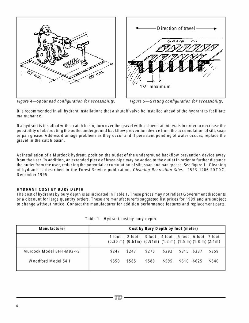
d. Spout Pad. The pad must be a minimum 60inches (1.5 m) by 60 inches (1.5 m) with astable, firm, slip resistant surface with amaximum slope of three percent. Design theslope to drain water away from the user. SeeFigure 4. If gratings are provided, the gratingspace on one side shall be not greater thanone-half inch (12.7 mm). If grating iselongated, the longest side shall be placedperpendicular to the dominant direction oftravel as shown in figure 5.
4
Figure 4—Spout pad configuration for accessibility. Figure 5—Grating configuration for accessibility.
It is recommended in all hydrant installations that a shutoff valve be installed ahead of the hydrant to facilitatemaintenance.
If a hydrant is installed with a catch basin, turn over the gravel with a shovel at intervals in order to decrease thepossibility of obstructing the outlet underground backflow prevention device from the accumulation of silt, soapor pan grease. Address drainage problems as they occur and if persistent ponding of water occurs, replace thegravel in the catch basin.
At installation of a Murdock hydrant, position the outlet of the underground backflow prevention device awayfrom the user. In addition, an extended piece of brass pipe may be added to the outlet in order to further distancethe outlet from the user, reducing the potential accumulation of silt, soap and pan grease. See figure 1. Cleaningof hydrants is described in the Forest Service publication, Cleaning Recreation Sites, 9523 1206-SDTDC,December 1995.
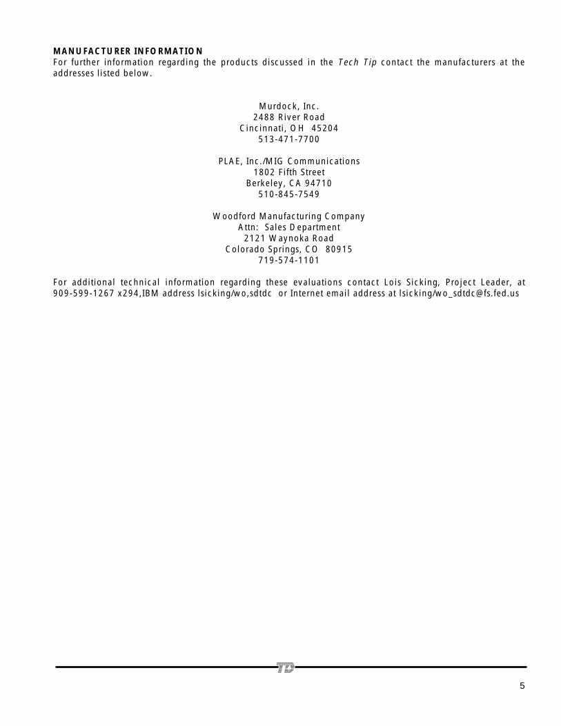
HYDRANT COST BY BURY DEPTHThe cost of hydrants by bury depth is as indicated in Table 1. These prices may not reflect Government discountsor a discount for large quantity orders. These are manufacturer’s suggested list prices for 1999 and are subjectto change without notice. Contact the manufacturer for addition performance features and replacement parts.
Table 1—Hydrant cost by bury depth.
Manufacturer Cost by Bury Depth by foot (meter)
1 foot 2 foot 3 foot 4 foot 5 foot 6 foot 7 foot (0.30 m) (0.61m) (0.91m) (1.2 m) (1.5 m) (1.8 m) (2.1m)
Murdock Model BFH-M92-FS $247 $247 $270 $292 $315 $337 $359
Woodford Model S4H $550 $565 $580 $595 $610 $625 $640
1/2" maximum
Direction of travel
MANUFACTURER INFORMATIONFor further information regarding the products discussed in the Tech Tip contact the manufacturers at theaddresses listed below.
Murdock, Inc.2488 River Road
Cincinnati, OH 45204513-471-7700
PLAE, Inc./MIG Communications1802 Fifth Street
Berkeley, CA 94710510-845-7549
Woodford Manufacturing CompanyAttn: Sales Department
2121 Waynoka RoadColorado Springs, CO 80915
719-574-1101
For additional technical information regarding these evaluations contact Lois Sicking, Project Leader, at909-599-1267 x294,IBM address lsicking/wo,sdtdc or Internet email address at lsicking/[email protected]
5

6

7
SINCE1853
Model BFHM-92-FSAntifreezing, Paddle Handle, Post Hydrant
With Attached Backflow Preventer, Self-draining
Suggested Specification
Model BFHM-92-FS delivers year-roundservice outside or in unheated buildings.The control valve is located below the frostline. A nozzle vacuum breaker preventswater contamination due to backflow. Thesupply column is evacuated through adouble-ball check valve located at thebottom connection, vented by a checkvalve mounted in the nozzle. This unitincorporates a self-closing valve.
Hydrant shall beMurdock model BFHM-92-FS. Unit shall becapable of year-round usein freezing or inclementweather.
Hydrant should stand 28to 36 inches high fromgrade level to the spoutoutlet. Unit shall extendbelow grade level so thatsupply inlet is positionedbelow frost line. Venteddouble-ball check valveshall be mounted below
frost line to evacuate waterfrom inner supply columnwhen valve is shut off.Check valve shall bemounted in nozzle to aidevacuation of supplycolumn. To prevent supplycontamination, vacuumbreaker shall be permanentlymounted to nozzle andthreaded for 3/4-inch hoseconnection.
Nozzle and inner supplyassembly shall incorporatesolid-brass castings.
Supply line and control rod shallbe mill-finish, galvanized steelpipe.
Phone (513) 471-7700 Fax (513) 471-3299
[email protected] River Road
Cincinnati, Ohio 45204
APPENDIX A. MURDOCK MODEL BFHM-92-FS HYDRANT
8
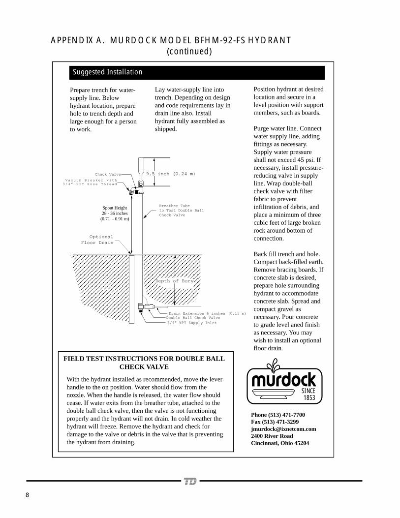
APPENDIX A. MURDOCK MODEL BFHM-92-FS HYDRANT (continued)
SINCE1853
Phone (513) 471-7700Fax (513) [email protected] River RoadCincinnati, Ohio 45204
FIELD TEST INSTRUCTIONS FOR DOUBLE BALLCHECK VALVE
With the hydrant installed as recommended, move the leverhandle to the on position. Water should flow from thenozzle. When the handle is released, the water flow shouldcease. If water exits from the breather tube, attached to thedouble ball check valve, then the valve is not functioningproperly and the hydrant will not drain. In cold weather thehydrant will freeze. Remove the hydrant and check fordamage to the valve or debris in the valve that is preventingthe hydrant from draining.
Prepare trench for water-supply line. Belowhydrant location, preparehole to trench depth andlarge enough for a personto work.
Lay water-supply line intotrench. Depending on designand code requirements lay indrain line also. Installhydrant fully assembled asshipped.
Position hydrant at desiredlocation and secure in alevel position with supportmembers, such as boards.
Purge water line. Connectwater supply line, addingfittings as necessary.Supply water pressureshall not exceed 45 psi. Ifnecessary, install pressure-reducing valve in supplyline. Wrap double-ballcheck valve with filterfabric to preventinfiltration of debris, andplace a minimum of threecubic feet of large brokenrock around bottom ofconnection.
Back fill trench and hole.Compact back-filled earth.Remove bracing boards. Ifconcrete slab is desired,prepare hole surroundinghydrant to accommodateconcrete slab. Spread andcompact gravel asnecessary. Pour concreteto grade level aned finishas necessary. You maywish to install an optionalfloor drain.
Suggested Installation
9.5 inch (0.24 m)
Depth of Bury
Optional
Floor Drain
Breather Tubeto Test Double BallCheck Valve
Check Valve
3/4" NPT Supply Inlet
Double Ball Check ValveDrain Extension 6 inches (0.15 m)
V a c u u m B r e a k e r w i t h3 / 4 ” N P T H o s e T h r e a d
Spout Height28 - 36 inches
(0.71 - 0.91 m)

9
APPENDIX B. WOODFORD MODEL S4H HYDRANT
10

11
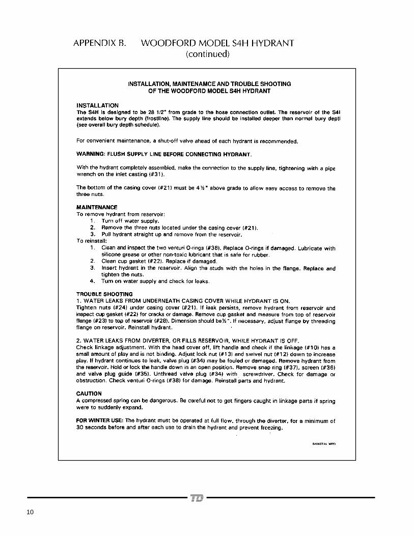
APPENDIX B. WOODFORD MODEL S4H HYDRANT (continued)
AUTOMATIC
RELEASE
PULL
DOWN
28 1/2"
12
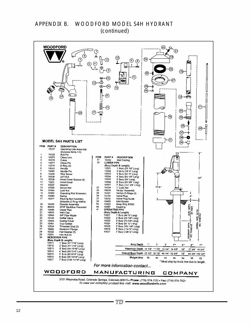
APPENDIX B. WOODFORD MODEL S4H HYDRANT (continued)

13
APPENDIX C. WOODFORD MODEL 37HD1 AND 37HD2 DOUBLE CHECK VALVE BACKFLOW PREVENTION DEVICE
14
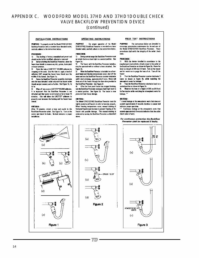
APPENDIX C. WOODFORD MODEL 37HD AND 37HD1DOUBLE CHECK VALVE BACKFLOW PREVENTION DEVICE (continued)

15

own employees. The use of trade, firm, or corporation names in thispublication is for the information and convenience of the reader anddoes not constitute an endorsement by the U.S. Department of Agricultureof any product or service to the exclusion of others that may be suitable.
The Forest Service, U.S. Department of Agriculture has developedthis information for the guidance of its employees, its contractors,and its cooperating Federal and State agencies, and is not responsiblefor the interpretation or use of this information by anyone except its