united states army warfighting center fort rucker, …€¦ · · 2012-01-21student handout...
TRANSCRIPT
United States Army Warfighting Center Fort Rucker, Alabama
October 2006
STUDENT HANDOUT
TITLE: CH-47D ELECTRICAL SYSTEM
FILE NUMBER: 011-2117-3
PROPONENT FOR THIS STUDENT HANDOUT IS:
110th Aviation Brigade ATTN: ATZQ-ATB-AD Fort Rucker, Alabama 36362-5000
FOREIGN DISCLOSURE RESTRICTIONS: This product/publication has been reviewed by the product developers in coordination with the Cargo Utility Branch/ Ft. Rucker foreign disclosure authority. This product is releasable to students from all requesting foreign countries without restrictions.
1

2
CH-47D ELECTRICAL SYSTEM
STUDENT HANDOUT
TERMINAL LEARNING OBJECTIVE (TLO): Action: Describe components, operational characteristics, functions, and limitations of the CH-47D Electrical System. Conditions: In a classroom, given a CH-47D Electrical System Trainer, Electrical System Diagram, and a student handout. Standards: Correctly answer in writing, without reference, five of seven questions pertaining to components, operational characteristics, limitations, and functions or malfunctions of the CH-47D Electrical System, In Accordance With (IAW) TM 1−1520−240−10 and the student handout. Safety Requirements: None. Risk Assessment Level: Low. Environmental Considerations: None. Evaluation: Each student will be evaluated on this block of instruction during the first written examination. This will be a criterion type examination requiring a GO on each scored unit. You will have 90 minutes for the exam.
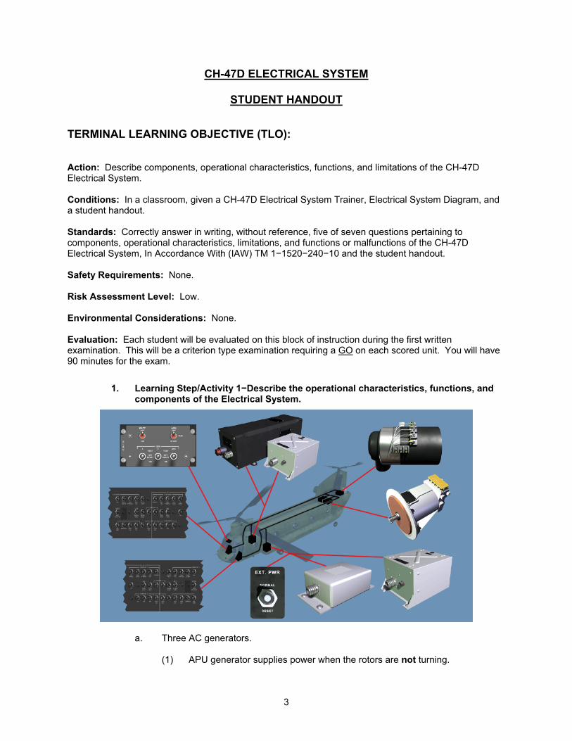
1. Learning Step/Activity 1−Describe the operational characteristics, functions, and components of the Electrical System.
a. Three AC generators.
(1) APU generator supplies power when the rotors are not turning.
3
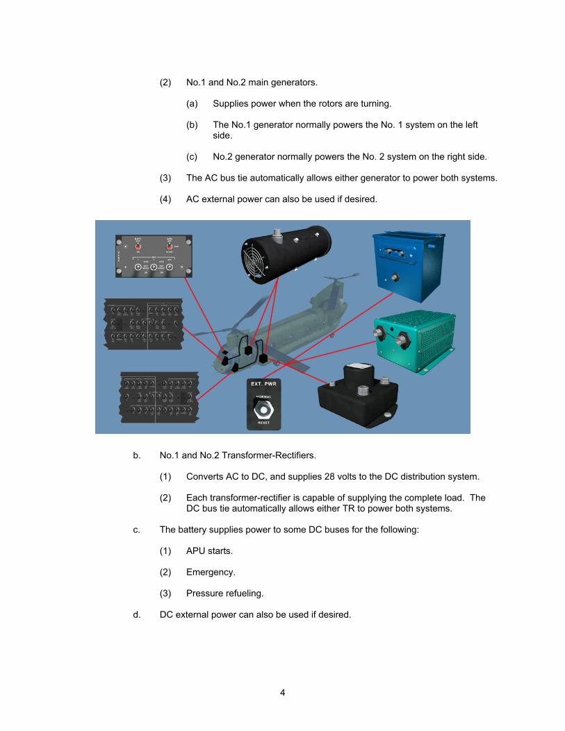
(2) No.1 and No.2 main generators.
(a) Supplies power when the rotors are turning. (b) The No.1 generator normally powers the No. 1 system on the left
side.
(c) No.2 generator normally powers the No. 2 system on the right side.
(3) The AC bus tie automatically allows either generator to power both systems.
(4) AC external power can also be used if desired.
b. No.1 and No.2 Transformer-Rectifiers.
(1) Converts AC to DC, and supplies 28 volts to the DC distribution system.
(2) Each transformer-rectifier is capable of supplying the complete load. The DC bus tie automatically allows either TR to power both systems.
c. The battery supplies power to some DC buses for the following:
(1) APU starts.
(2) Emergency.
(3) Pressure refueling.
d. DC external power can also be used if desired.
4
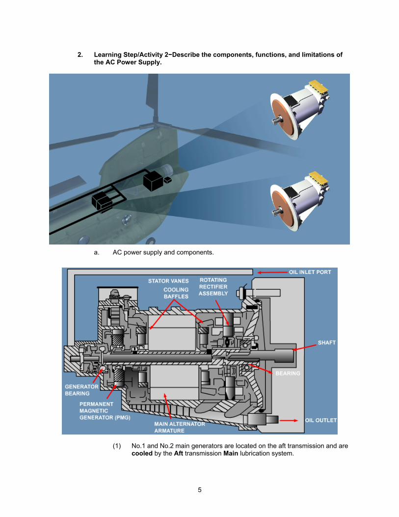
2. Learning Step/Activity 2−Describe the components, functions, and limitations of the AC Power Supply.
a. AC power supply and components.
(1) No.1 and No.2 main generators are located on the aft transmission and are cooled by the Aft transmission Main lubrication system.
5
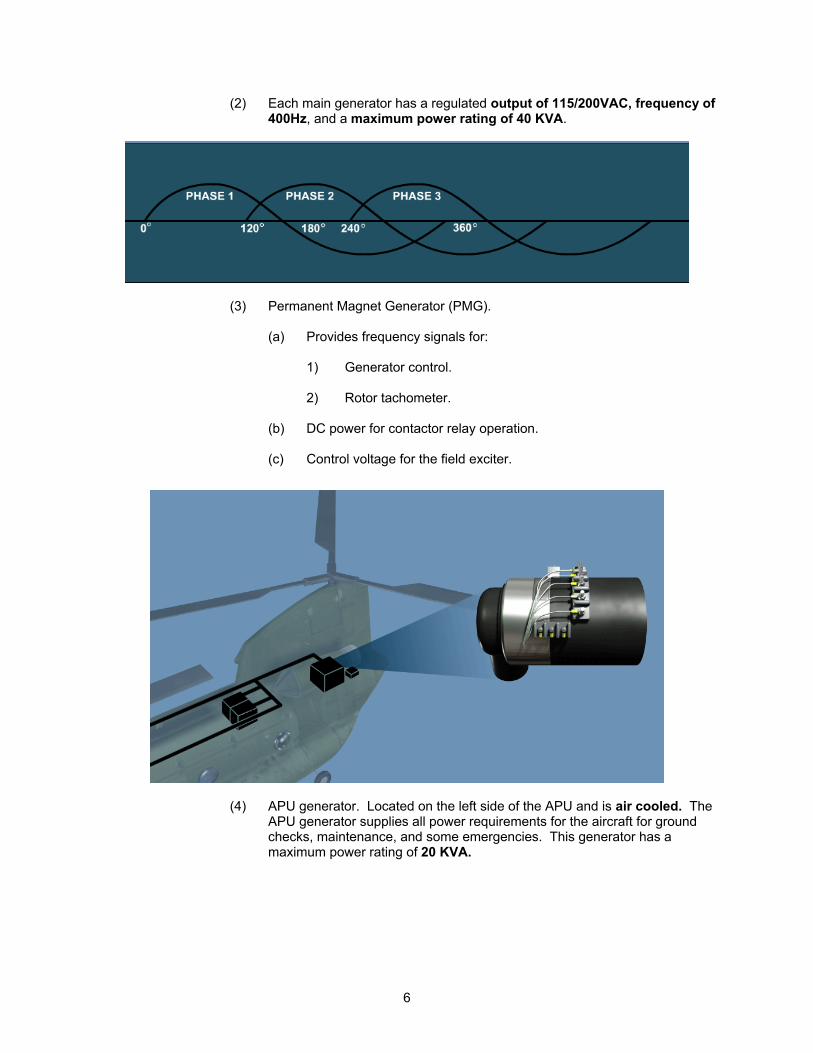
(2) Each main generator has a regulated output of 115/200VAC, frequency of 400Hz, and a maximum power rating of 40 KVA.
(3) Permanent Magnet Generator (PMG).
(a) Provides frequency signals for:
1) Generator control.
2) Rotor tachometer.
(b) DC power for contactor relay operation. (c) Control voltage for the field exciter.
(4) APU generator. Located on the left side of the APU and is air cooled. The APU generator supplies all power requirements for the aircraft for ground checks, maintenance, and some emergencies. This generator has a maximum power rating of 20 KVA.
6
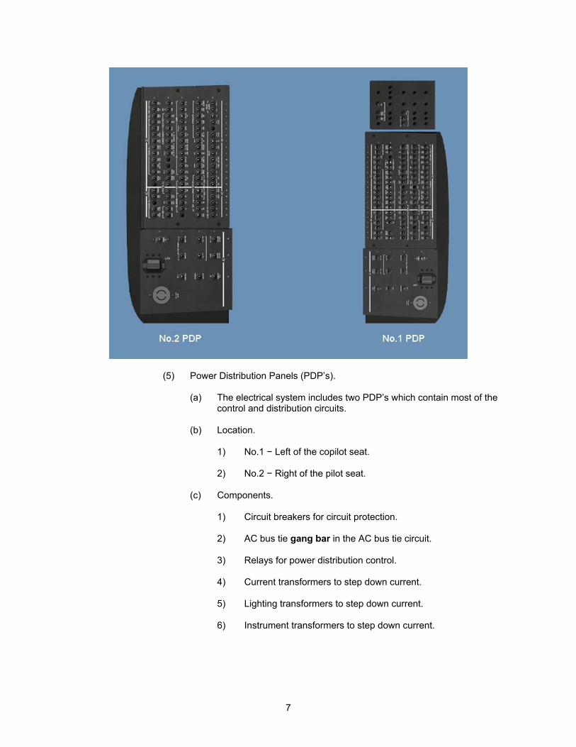
(5) Power Distribution Panels (PDP’s).
(a) The electrical system includes two PDP’s which contain most of the control and distribution circuits.
(b) Location.
1) No.1 − Left of the copilot seat.
2) No.2 − Right of the pilot seat.
(c) Components.
1) Circuit breakers for circuit protection.
2) AC bus tie gang bar in the AC bus tie circuit.
3) Relays for power distribution control.
4) Current transformers to step down current.
5) Lighting transformers to step down current.
6) Instrument transformers to step down current.
7
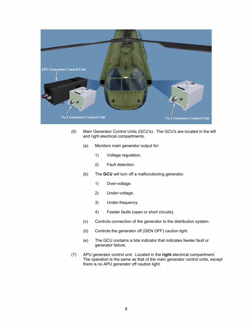
(6) Main Generator Control Units (GCU’s). The GCU's are located in the left and right electrical compartments.
(a) Monitors main generator output for:
1) Voltage regulation.
2) Fault detection.
(b) The GCU will turn off a malfunctioning generator.
1) Over-voltage.
2) Under-voltage.
3) Under-frequency.
4) Feeder faults (open or short circuits).
(c) Controls connection of the generator to the distribution system.
(d) Controls the generator off (GEN OFF) caution light.
(e) The GCU contains a bite indicator that indicates feeder fault or generator failure.
(7) APU generator control unit. Located in the right electrical compartment.
The operation is the same as that of the main generator control units, except there is no APU generator off caution light.
8
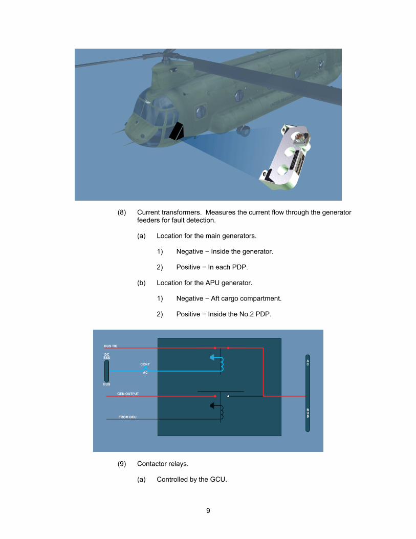
(8) Current transformers. Measures the current flow through the generator feeders for fault detection.
(a) Location for the main generators.
1) Negative − Inside the generator.
2) Positive − In each PDP.
(b) Location for the APU generator.
1) Negative − Aft cargo compartment.
2) Positive − Inside the No.2 PDP.
(9) Contactor relays.
(a) Controlled by the GCU.
9
(b) Purpose:
1) Connects the power source to the bus.
2) Disconnects an inoperative generator from the bus to prevent a
reverse current flow.
3) Completes AC bus tie when required.
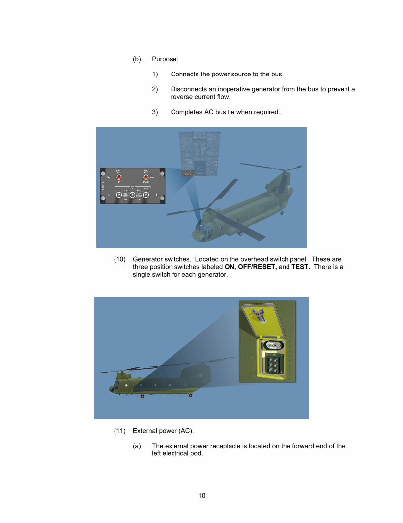
(10) Generator switches. Located on the overhead switch panel. These are three position switches labeled ON, OFF/RESET, and TEST. There is a single switch for each generator.
(11) External power (AC).
(a) The external power receptacle is located on the forward end of the left electrical pod.
10
(b) External power control unit.
1) Located in the left electrical compartment.
2) Prevents unacceptable external power from being connected to the aircraft.
3) Controls the external power contactor relay.
4) External power switch is used to reset the external power
control unit if the power has been automatically shut off.
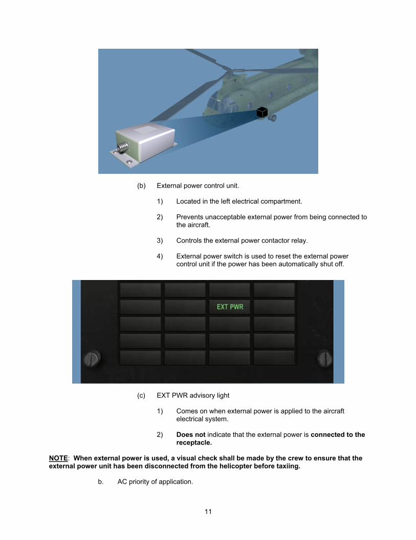
(c) EXT PWR advisory light
1) Comes on when external power is applied to the aircraft electrical system.
2) Does not indicate that the external power is connected to the
receptacle. NOTE: When external power is used, a visual check shall be made by the crew to ensure that the external power unit has been disconnected from the helicopter before taxiing.
b. AC priority of application.
11
(1) The priority of application ensure only one source of power can be
connected to a bus at a time. This is accomplished by the use of contactor relays.
(2) Order of priority.
(a) No.1 and 2 main generators, either one or both.
(b) APU generator.
(c) External power.
3. Learning Step/Activity 3−Describe the DC Power Supply.
a. DC power supply and components.
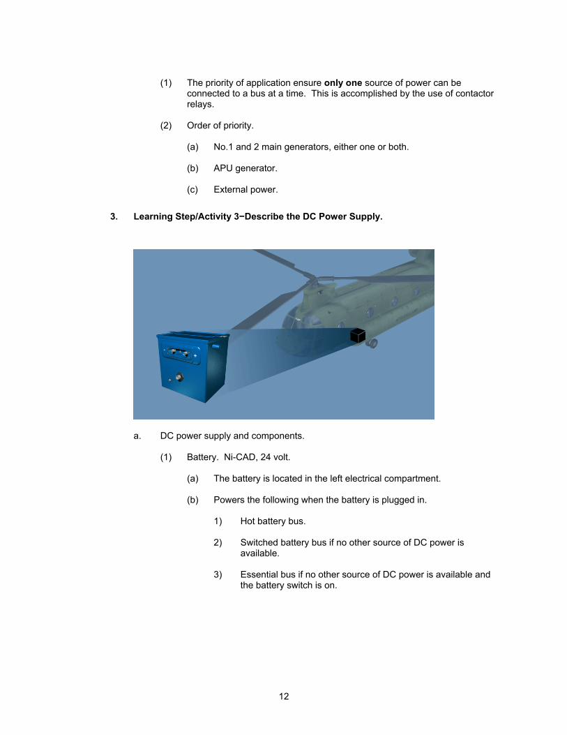
(1) Battery. Ni-CAD, 24 volt.
(a) The battery is located in the left electrical compartment.
(b) Powers the following when the battery is plugged in.
1) Hot battery bus.
2) Switched battery bus if no other source of DC power is available.
3) Essential bus if no other source of DC power is available and
the battery switch is on.
12
(2) Battery charger. The charger is located in the left electrical compartment.
(a) Function.
1) Charge the battery.
2) Monitor the battery for overheating, battery cell imbalance, and defective temperature sensor.
(b) Powered by the No.1 AC bus through the BATT CHGR circuit
breaker.
(c) Battery charge status lights.
1) Battery charging, less than 80%.
2) Charge complete, more than 80%.
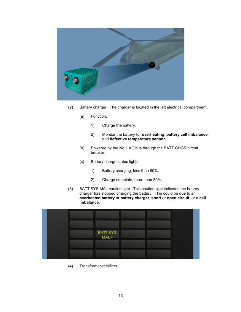
(3) BATT SYS MAL caution light. This caution light indicates the battery charger has stopped charging the battery. This could be due to an overheated battery or battery charger, short or open circuit, or a cell imbalance.
(4) Transformer-rectifiers.
13
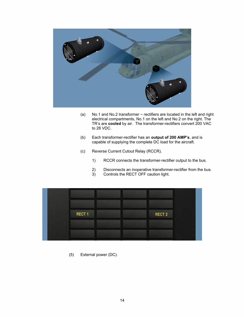
(a) No.1 and No.2 transformer − rectifiers are located in the left and right electrical compartments, No.1 on the left and No.2 on the right. The TR’s are cooled by air. The transformer-rectifiers convert 200 VAC to 28 VDC.
(b) Each transformer-rectifier has an output of 200 AMP’s, and is
capable of supplying the complete DC load for the aircraft.
(c) Reverse Current Cutout Relay (RCCR).
1) RCCR connects the transformer-rectifier output to the bus.
2) Disconnects an inoperative transformer-rectifier from the bus. 3) Controls the RECT OFF caution light.
(5) External power (DC).
14
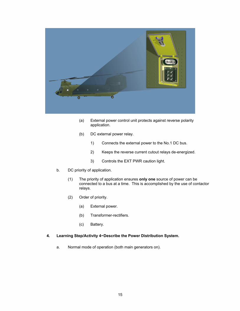
(a) External power control unit protects against reverse polarity application.
(b) DC external power relay.
1) Connects the external power to the No.1 DC bus.
2) Keeps the reverse current cutout relays de-energized.
3) Controls the EXT PWR caution light.
b. DC priority of application.
(1) The priority of application ensures only one source of power can be
connected to a bus at a time. This is accomplished by the use of contactor relays.
(2) Order of priority.
(a) External power.
(b) Transformer-rectifiers.
(c) Battery.
4. Learning Step/Activity 4−Describe the Power Distribution System.
a. Normal mode of operation (both main generators on).
15
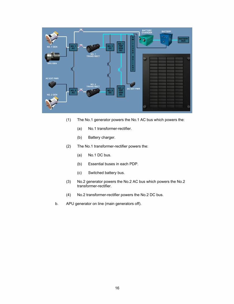
(1) The No.1 generator powers the No.1 AC bus which powers the:
(a) No.1 transformer-rectifier.
(b) Battery charger.
(2) The No.1 transformer-rectifier powers the:
(a) No.1 DC bus.
(b) Essential buses in each PDP.
(c) Switched battery bus.
(3) No.2 generator powers the No.2 AC bus which powers the No.2 transformer-rectifier.
(4) No.2 transformer-rectifier powers the No.2 DC bus.
b. APU generator on line (main generators off).
16
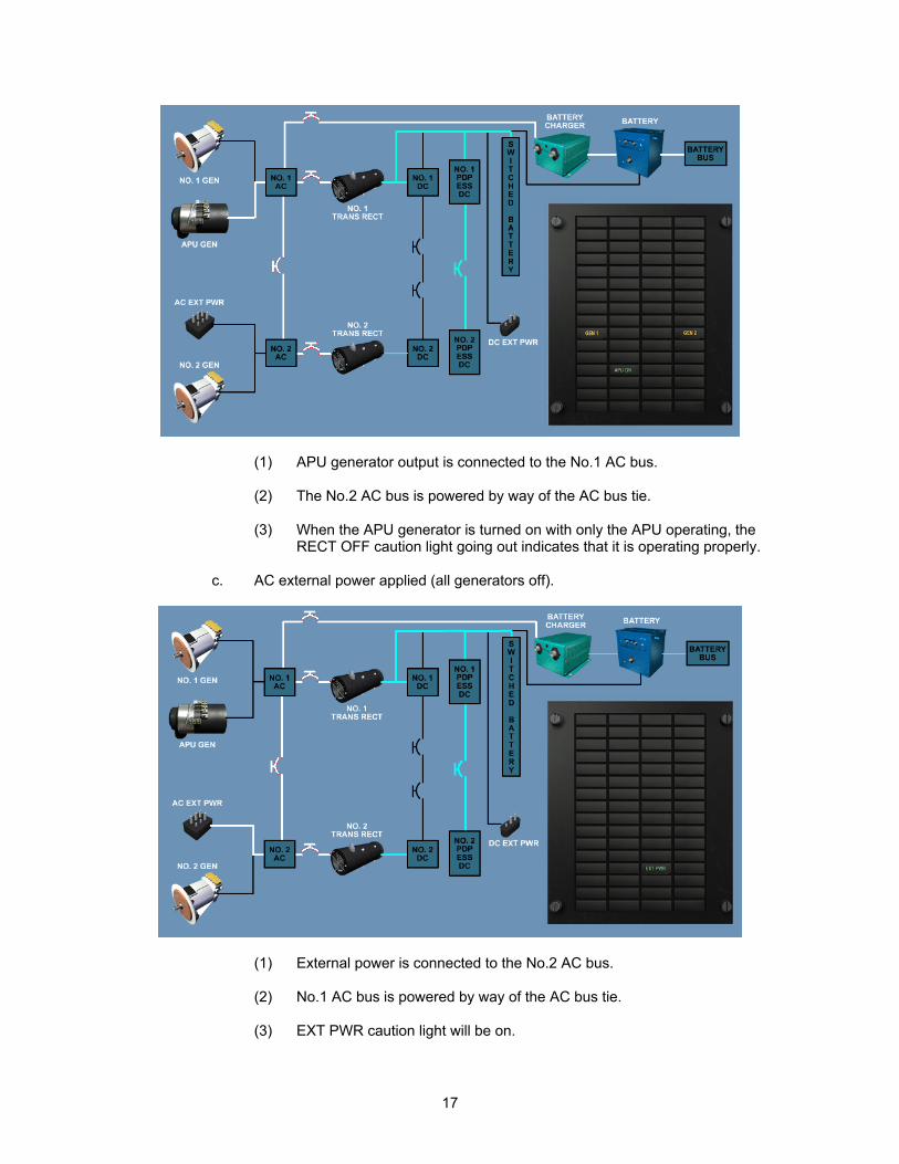
(1) APU generator output is connected to the No.1 AC bus.
(2) The No.2 AC bus is powered by way of the AC bus tie.
(3) When the APU generator is turned on with only the APU operating, the RECT OFF caution light going out indicates that it is operating properly.
c. AC external power applied (all generators off).
(1) External power is connected to the No.2 AC bus.
(2) No.1 AC bus is powered by way of the AC bus tie.
(3) EXT PWR caution light will be on.
17
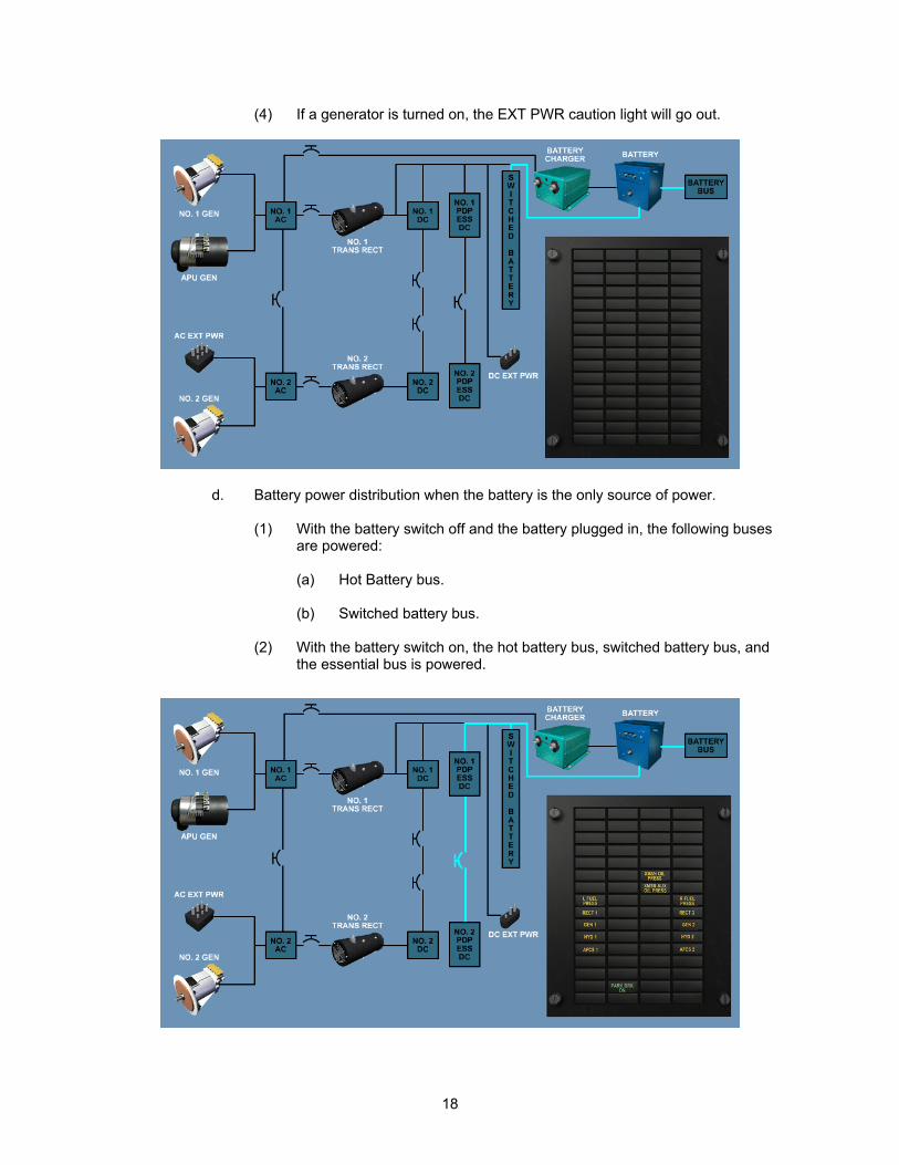
(4) If a generator is turned on, the EXT PWR caution light will go out.
d. Battery power distribution when the battery is the only source of power.
(1) With the battery switch off and the battery plugged in, the following buses are powered:
(a) Hot Battery bus.
(b) Switched battery bus.
(2) With the battery switch on, the hot battery bus, switched battery bus, and
the essential bus is powered.
18
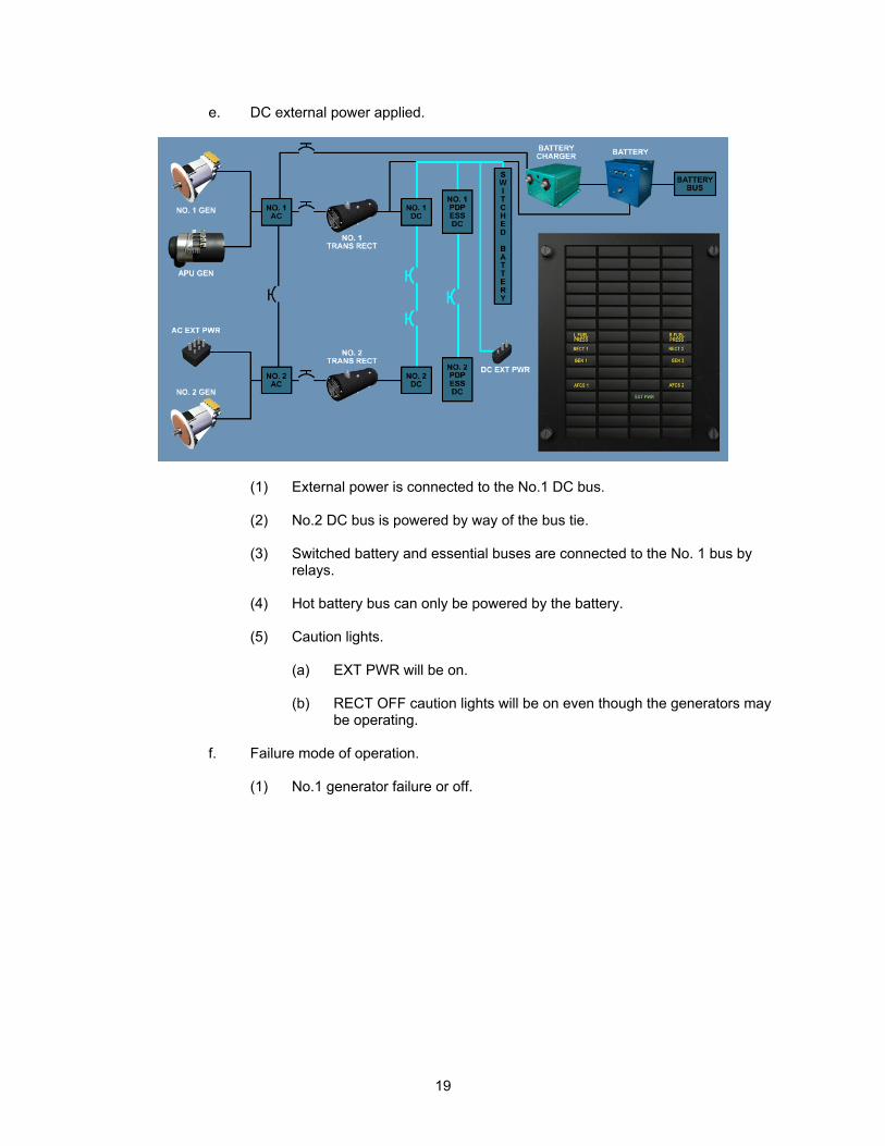
e. DC external power applied.
(1) External power is connected to the No.1 DC bus.
(2) No.2 DC bus is powered by way of the bus tie.
(3) Switched battery and essential buses are connected to the No. 1 bus by relays.
(4) Hot battery bus can only be powered by the battery.
(5) Caution lights.
(a) EXT PWR will be on.
(b) RECT OFF caution lights will be on even though the generators may
be operating.
f. Failure mode of operation.
(1) No.1 generator failure or off.
19
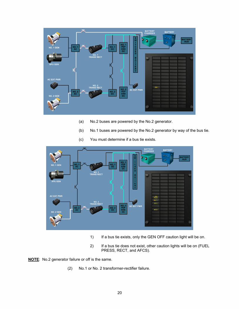
(a) No.2 buses are powered by the No.2 generator.
(b) No.1 buses are powered by the No.2 generator by way of the bus tie.
(c) You must determine if a bus tie exists.
1) If a bus tie exists, only the GEN OFF caution light will be on.
2) If a bus tie does not exist, other caution lights will be on (FUEL PRESS, RECT, and AFCS).
NOTE: No.2 generator failure or off is the same.
(2) No.1 or No. 2 transformer-rectifier failure.
20
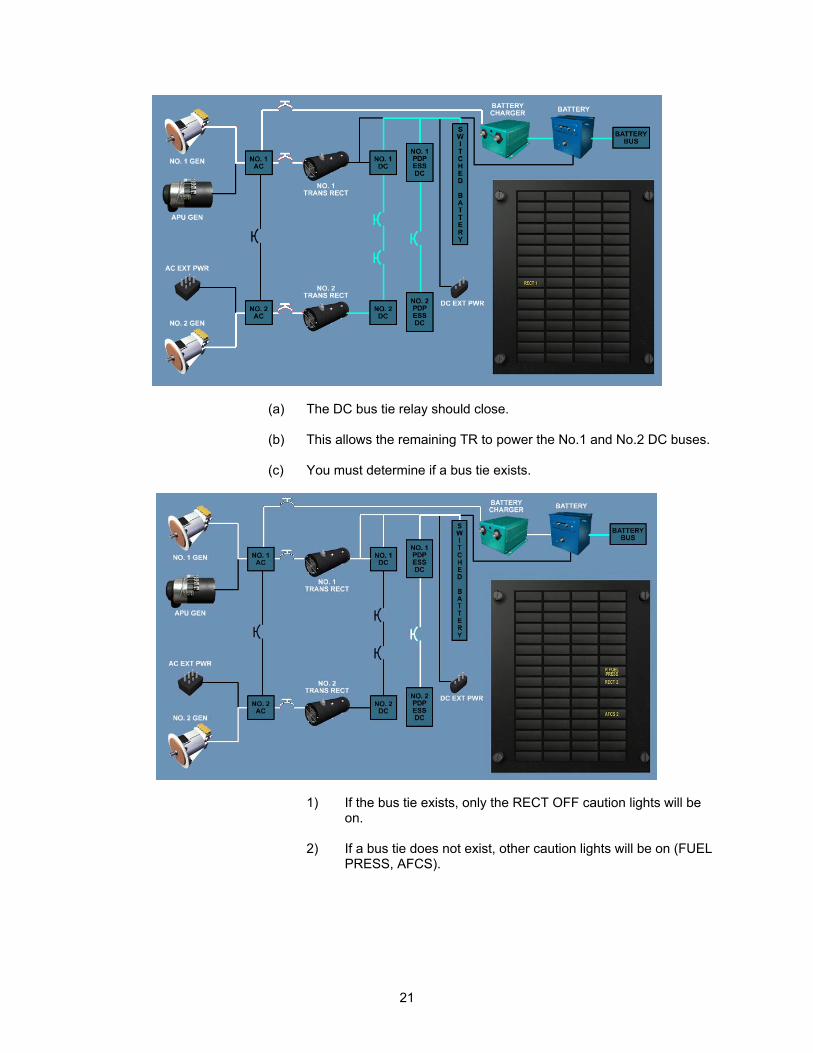
(a) The DC bus tie relay should close.
(b) This allows the remaining TR to power the No.1 and No.2 DC buses. (c) You must determine if a bus tie exists.
1) If the bus tie exists, only the RECT OFF caution lights will be on.
2) If a bus tie does not exist, other caution lights will be on (FUEL
PRESS, AFCS).
21
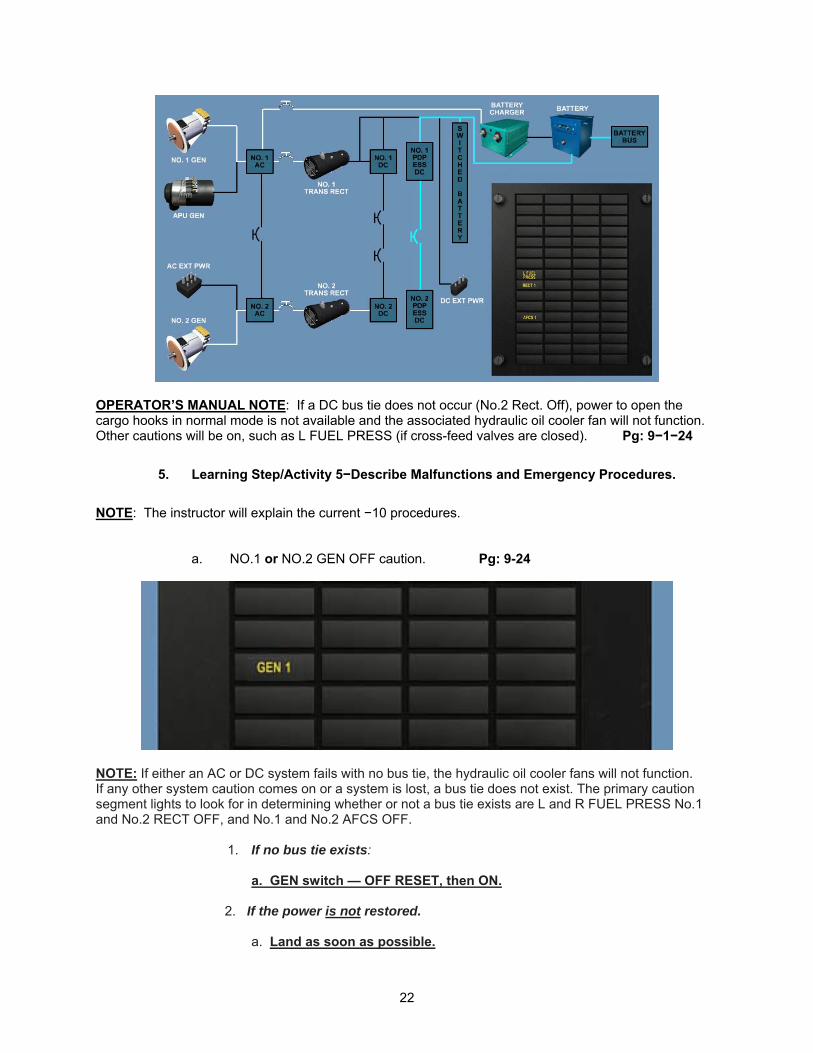
OPERATOR’S MANUAL NOTE: If a DC bus tie does not occur (No.2 Rect. Off), power to open the cargo hooks in normal mode is not available and the associated hydraulic oil cooler fan will not function. Other cautions will be on, such as L FUEL PRESS (if cross-feed valves are closed). Pg: 9−1−24
5. Learning Step/Activity 5−Describe Malfunctions and Emergency Procedures.
NOTE: The instructor will explain the current −10 procedures.
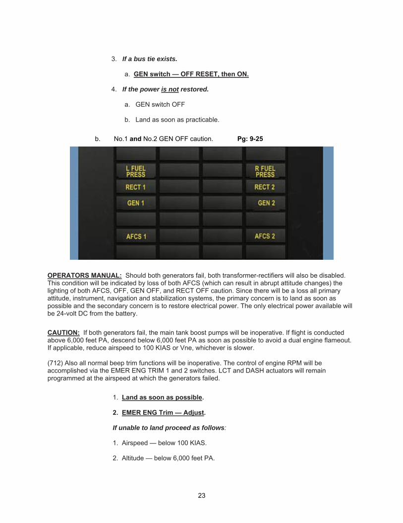
a. NO.1 or NO.2 GEN OFF caution. Pg: 9-24
NOTE: If either an AC or DC system fails with no bus tie, the hydraulic oil cooler fans will not function. If any other system caution comes on or a system is lost, a bus tie does not exist. The primary caution segment lights to look for in determining whether or not a bus tie exists are L and R FUEL PRESS No.1 and No.2 RECT OFF, and No.1 and No.2 AFCS OFF.
1. If no bus tie exists:
a. GEN switch — OFF RESET, then ON. 2. If the power is not restored.
a. Land as soon as possible.
22
3. If a bus tie exists.
a. GEN switch — OFF RESET, then ON.
4. If the power is not restored.
a. GEN switch OFF b. Land as soon as practicable.
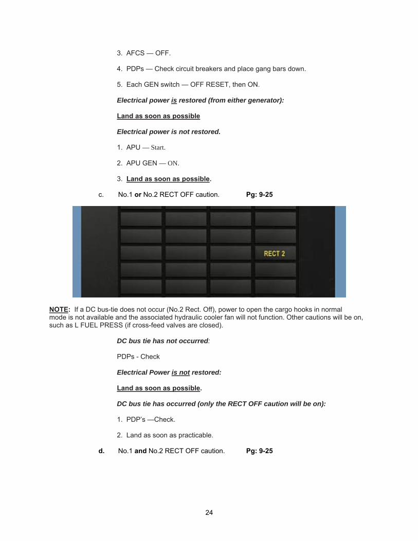
b. No.1 and No.2 GEN OFF caution. Pg: 9-25
OPERATORS MANUAL: Should both generators fail, both transformer-rectifiers will also be disabled. This condition will be indicated by loss of both AFCS (which can result in abrupt attitude changes) the lighting of both AFCS, OFF, GEN OFF, and RECT OFF caution. Since there will be a loss all primary attitude, instrument, navigation and stabilization systems, the primary concern is to land as soon as possible and the secondary concern is to restore electrical power. The only electrical power available will be 24-volt DC from the battery.
CAUTION: If both generators fail, the main tank boost pumps will be inoperative. If flight is conducted above 6,000 feet PA, descend below 6,000 feet PA as soon as possible to avoid a dual engine flameout. If applicable, reduce airspeed to 100 KIAS or Vne, whichever is slower. (712) Also all normal beep trim functions will be inoperative. The control of engine RPM will be accomplished via the EMER ENG TRIM 1 and 2 switches. LCT and DASH actuators will remain programmed at the airspeed at which the generators failed.
1. Land as soon as possible. 2. EMER ENG Trim — Adjust. If unable to land proceed as follows: 1. Airspeed — below 100 KIAS. 2. Altitude — below 6,000 feet PA.
23
3. AFCS — OFF. 4. PDPs — Check circuit breakers and place gang bars down. 5. Each GEN switch — OFF RESET, then ON. Electrical power is restored (from either generator): Land as soon as possible Electrical power is not restored. 1. APU — Start. 2. APU GEN — ON. 3. Land as soon as possible.
c. No.1 or No.2 RECT OFF caution. Pg: 9-25
NOTE: If a DC bus-tie does not occur (No.2 Rect. Off), power to open the cargo hooks in normal mode is not available and the associated hydraulic cooler fan will not function. Other cautions will be on, such as L FUEL PRESS (if cross-feed valves are closed).
DC bus tie has not occurred: PDPs - Check Electrical Power is not restored: Land as soon as possible. DC bus tie has occurred (only the RECT OFF caution will be on): 1. PDP’s —Check. 2. Land as soon as practicable.
d. No.1 and No.2 RECT OFF caution. Pg: 9-25
24
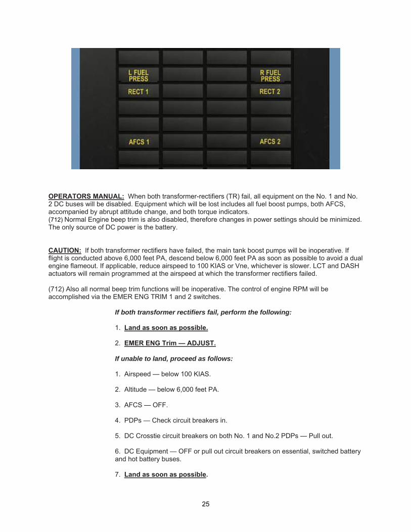
OPERATORS MANUAL: When both transformer-rectifiers (TR) fail, all equipment on the No. 1 and No. 2 DC buses will be disabled. Equipment which will be lost includes all fuel boost pumps, both AFCS, accompanied by abrupt attitude change, and both torque indicators. (712) Normal Engine beep trim is also disabled, therefore changes in power settings should be minimized. The only source of DC power is the battery. CAUTION: If both transformer rectifiers have failed, the main tank boost pumps will be inoperative. If flight is conducted above 6,000 feet PA, descend below 6,000 feet PA as soon as possible to avoid a dual engine flameout. If applicable, reduce airspeed to 100 KIAS or Vne, whichever is slower. LCT and DASH actuators will remain programmed at the airspeed at which the transformer rectifiers failed. (712) Also all normal beep trim functions will be inoperative. The control of engine RPM will be accomplished via the EMER ENG TRIM 1 and 2 switches.
If both transformer rectifiers fail, perform the following: 1. Land as soon as possible. 2. EMER ENG Trim — ADJUST. If unable to land, proceed as follows: 1. Airspeed — below 100 KIAS. 2. Altitude — below 6,000 feet PA. 3. AFCS — OFF. 4. PDPs — Check circuit breakers in. 5. DC Crosstie circuit breakers on both No. 1 and No.2 PDPs — Pull out. 6. DC Equipment — OFF or pull out circuit breakers on essential, switched battery and hot battery buses. 7. Land as soon as possible.
25
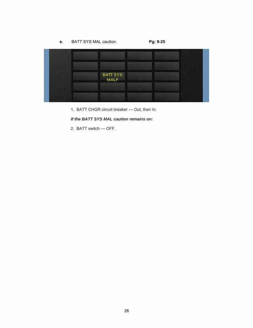
e. BATT SYS MAL caution. Pg: 9-25
1. BATT CHGR circuit breaker — Out, then In. If the BATT SYS MAL caution remains on: 2. BATT switch — OFF.
26
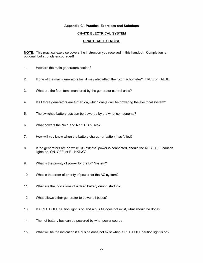
Appendix C - Practical Exercises and Solutions
CH-47D ELECTRICAL SYSTEM
PRACTICAL EXERCISE NOTE: This practical exercise covers the instruction you received in this handout. Completion is optional, but strongly encouraged! 1. How are the main generators cooled? 2. If one of the main generators fail, it may also affect the rotor tachometer? TRUE or FALSE. 3. What are the four items monitored by the generator control units? 4. If all three generators are turned on, which one(s) will be powering the electrical system? 5. The switched battery bus can be powered by the what components? 6. What powers the No.1 and No.2 DC buses? 7. How will you know when the battery charger or battery has failed? 8. If the generators are on while DC external power is connected, should the RECT OFF caution
lights be, ON, OFF, or BLINKING? 9. What is the priority of power for the DC System? 10. What is the order of priority of power for the AC system? 11. What are the indications of a dead battery during startup? 12. What allows either generator to power all buses? 13. If a RECT OFF caution light is on and a bus tie does not exist, what should be done? 14. The hot battery bus can be powered by what power source 15. What will be the indication if a bus tie does not exist when a RECT OFF caution light is on?
27
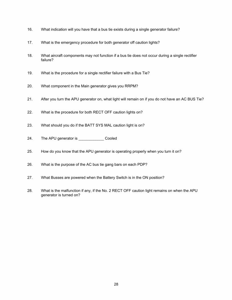
16. What indication will you have that a bus tie exists during a single generator failure? 17. What is the emergency procedure for both generator off caution lights? 18. What aircraft components may not function if a bus tie does not occur during a single rectifier
failure? 19. What is the procedure for a single rectifier failure with a Bus Tie? 20. What component in the Main generator gives you RRPM? 21. After you turn the APU generator on, what light will remain on if you do not have an AC BUS Tie? 22. What is the procedure for both RECT OFF caution lights on? 23. What should you do if the BATT SYS MAL caution light is on? 24. The APU generator is ____________ Cooled 25. How do you know that the APU generator is operating properly when you turn it on? 26. What is the purpose of the AC bus tie gang bars on each PDP? 27. What Busses are powered when the Battery Switch is in the ON position? 28. What is the malfunction if any, if the No. 2 RECT OFF caution light remains on when the APU
generator is turned on?
28
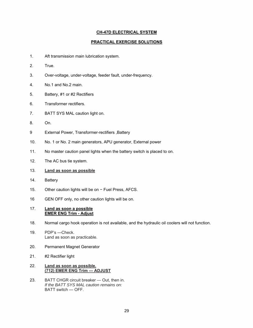
CH-47D ELECTRICAL SYSTEM
PRACTICAL EXERCISE SOLUTIONS
1. Aft transmission main lubrication system. 2. True. 3. Over-voltage, under-voltage, feeder fault, under-frequency. 4. No.1 and No.2 main. 5. Battery, #1 or #2 Rectifiers 6. Transformer rectifiers. 7. BATT SYS MAL caution light on. 8. On. 9 External Power, Transformer-rectifiers ,Battery 10. No. 1 or No. 2 main generators, APU generator, External power 11. No master caution panel lights when the battery switch is placed to on. 12. The AC bus tie system. 13. Land as soon as possible 14. Battery 15. Other caution lights will be on − Fuel Press, AFCS. 16 GEN OFF only, no other caution lights will be on. 17. Land as soon a possible
EMER ENG Trim - Adjust 18. Normal cargo hook operation is not available, and the hydraulic oil coolers will not function. 19. PDP’s —Check.
Land as soon as practicable. 20. Permanent Magnet Generator 21. #2 Rectifier light 22. Land as soon as possible.
(712) EMER ENG Trim — ADJUST 23. BATT CHGR circuit breaker — Out, then in.
If the BATT SYS MAL caution remains on: BATT switch — OFF.
29
24. Air Cooled 25. When the RECT OFF caution lights go out. 26. To disable the AC bus tie system. 27. Hot battery bus
Switched battery bus Essential bus
28. AC bus tie does not exist.
30